SERVICE MANUAL - Taller de Electró · PDF fileidentical to those in the original...
19
SERVICE MANUAL Product Type: LCD TV Chassis: ML-024A Manual Part #: 3828VD0131Y Product Year: 2003 L15V26D Model Series: CONTENTS Specifications .............................................................. 4 Description of Controls ................................................. 5 Adjustment Instructions ................................................ 8 Diagrams ................................................................... 10 Parts List ................................................................... 13 Schematics .................................................................... Published June 2003 by Technical Publications Zenith Electronics Corporation 201 James Record Road Huntsville, Alabama 35824-1513 Copyright © 2003 by Zenith Electronics Corporation Printed in Korea
Transcript of SERVICE MANUAL - Taller de Electró · PDF fileidentical to those in the original...
SERVICE MANUALProduct Type: LCD TVChassis: ML-024AManual Part #: 3828VD0131YProduct Year: 2003
L15V26D
Model Series:
CONTENTSSpecifications ..............................................................4Description of Controls .................................................5Adjustment Instructions ................................................8Diagrams ...................................................................10Parts List ...................................................................13Schematics ....................................................................
Published June 2003by Technical Publications
Zenith Electronics Corporation201 James Record Road
Huntsville, Alabama 35824-1513
Copyright © 2003 by Zenith Electronics Corporation
Printed in Korea

- 2 -
PRODUCT SAFETY
IMPORTANT SAFETY NOTICEThis manual was prepared for use only by properly trained audiovisual servicetechnicians. When servicing this product, under no circumstances should theoriginal design be modified or altered without permission from ZenithElectronics Corporation. All components should be replaced only with typesidentical to those in the original circuit and their physical location, wiring, andlead dress must conform to original layout upon completion of repairs. If anyfuse (or Fusible Resistor) in this TV receiver is blown, replace it only with thefactory specified fuse type and rating. When replacing a high wattage resistor(Oxide Metal Film Resistor, over 1W), keep the resistor 10mm away from PCB.Always keep wires away from high voltage or high temperature parts.
Special components are also used to prevent shock and fire hazard.These components are indicated by the letter “x” included in their componentdesignators and are required to maintain safe performance. No deviations areallowed without prior approval by Zenith Electronics Corporation. Service workshould be performed only after you are thoroughly familiar with these safetychecks and servicing guidelines.
Circuit diagrams may occasionally differ from the actual circuit used.This way, implementation of the latest safety and performance improvementchanges into the set is not delayed until the new service literature is printed.
CAUTION: Do not attempt to modify this product in any way. Never perform customized installations without manufacturer’sapproval.Unauthorized modifications will not only void the warranty, but maylead to property damage or user injury.
GENERAL GUIDANCEAn lsolation Transformer should always be used during the servicingof a receiver whose chassis is not isolated from the AC power line. Use atransformer of adequate power rating to protect against personal injury fromelectrical shocks. It will also protect the receiver and its components from beingdamaged by accidental shorts of the circuitry that may be inadvertentlyintroduced during the service operation.
Before returning the receiver to the customer, always perform an AC leakagecurrent check on the exposed metallic parts of the cabinet, such as antennas,terminals, etc., to be sure the set is safe to operatewithout damage of electrical shock.
LEAKAGE CURRENT COLD CHECK(ANTENNA COLD CHECK)With the instrument AC plug removed from AC source, connect an electricaljumper across the two AC plug prongs. Place the AC switch in the on position,connect one lead of ohm-meter to the AC plug prongs tied together and touchother ohm-meter lead in turn to each exposed metallic parts such as antennaterminals, phone jacks, etc. If the exposed metallic part has a return path to thechassis, the measured resistance should be between 1MΩ and 5.2MΩ. Whenthe exposed metal has no return path to the chassis the reading must beinfinite. Any other abnormality that exists must be corrected beforethe receiver is returned to the customer.
ELECTROSTATICALLY SENSITIVE DEVICESSome semiconductor (solid-state) devices can be damaged easily by staticelectricity. Such components commonly are called Electrostatically Sensitive(ES) Devices. Examples of typical ES devices are integrated circuits and somefield-effect transistors and semiconductor “chip” components. The followingtechniques should be used to help reduce the incidence of component damagecaused by static electricity.
1. Immediately before handling any semiconductor component orsemiconductor-equipped assembly, drain off any electrostatic charge on thebody by touching a known earth ground. Alternatively, obtain and wear acommercially available discharging wrist strap device, which should beremoved for potential shock reasons prior to applying power to the unit undertest.
2. After removing an electrical assembly equipped with ES devices, place theassembly on a conductive surface such as an ESD mat, to preventelectrostatic charge buildup or exposure of the assembly.
3. Use only a grounded-tip soldering iron to solder or unsolder ES devices.4. Use only an anti-static solder removal device. Some solder removal devices
not classified as “anti-static” can generate electrical charges sufficient todamage ES devices.
5. Do not use freon-propelled chemicals. These can generate electrical chargesufficient to damage ES devices.
6. Do not remove a replacement ES device from its protective package untilimmediately before you are ready to install it. (Most replacement ES devicesare packaged with leads electrically shorted together by conductive foam,aluminum foil, or comparable conductive material.)
7. Immediately before removing the protective material from the leads of areplacement ES device, touch the protective material to the chassis or circuitassembly into which the device will be installed.
Caution: Be sure no power is applied to the chassis or circuit, and observeall other safety precautions.
8. Minimize bodily motions when handling unpackaged replacement ESdevices. (Otherwise, seemingly harmless motion, such as the brushingtogether of your clothing or the lifting of your foot from a carpeted floor, cangenerate static electricity sufficient to damage an ES device.)
REGULATORY INFORMATIONThis equipment has been tested and found to comply with the limits for a ClassB digital device, pursuant to Part 15 of the FCC Rules.These limits are designed to provide reasonable protection against harmfulinterference when the equipment is operated in a residential installation. Thisequipment generates, uses and can radiate radio frequency energy and, if notinstalled and used in accordance with the instruction manual, may causeharmful interference to radio communications. However, there is no guaranteethat interference will not occur in a particular installation. If this equipment doescause harmful interference to radio or television reception, which can bedetermined by turning the equipment off and on, the user is encouraged to tryto correct the interference by one or more of the following measures: Reorientor relocate the receiving antenna; Increase the separation between theequipment and receiver; Connect the equipment into an outlet on a circuitdifferent from that towhich the receiver is connected; Consult the dealer or an experienced radio/TVtechnician for help.
The responsible party for this device’s compliance is:
Zenith Electronics Corporation201 James Record RoadHuntsville, AL 35824, USADigital TV Hotline: 1-800-243-0000

- 3 -
SPECIFICATIONS.................................................................4
DESCRIPTION OF CONTROLS...........................................5
ADJUSTMENT INSTRUCTIONS ..........................................8
BLOCK DIAGRAM...............................................................10
EXPLODED VIEW...............................................................12
EXPLODED VIEW PARTS LIST .........................................13
REPLACEMENT PARTS LIST............................................14
SCHEMATIC DIAGRAM..........................................................
PRINTED CIRCUIT BOARD ...................................................
TABLE OF CONTENTS

- 4 -
SPECIFICATIONS
Model L15V26D
Horizontal size (inches) 15.2
Height (inches) 14.5
Depth (inches) 7Weight (pounds) 16
Power requirements AC 120V, 60Hz
Television system NTSC
Television channels VHF : 2 ~ 13, UHF : 14 ~ 69Cable : 1 ~ 125
Tube LCD Panel
Power consumption 45 W
External antenna impedance 75 Ω
Audio output 1 W + 1 W
Speaker outputs 8 Ω X 2
External input ports Power cord socket 1Component (480i/480p/720p/1080i) input 1 set S-VIDEO input 1Headphone jack 1Video/Audio input set 1PC input jack 1PC sound jack 1Antenna input 1
Power supply cord set Standard North America three wire earth-grounding with flexible cord SJT type or higher type.

- 5 -
DESCRIPTION OF CONTROLS
Front of the Front of the TVTV
chvol
enterm
enutv/video
on/off
Side Control PanelSide Control Panel
TV/Video Button
Enter Button
Channel Buttons
On/Off Button
Menu Button
Volume Buttons
Remote Control Sensor
Power/Standby indicatorIlluminates red in standbymode, Illuminates green whenthe TV is turned on.

- 6 -
DESCRIPTION OF CONTROLS
+75 Ω
ANT INPC INPUTS-VIDEO H/P PCSOUND(120V)
AC INPUTVIDEO IN
RLVIDEO AUDIO(MONO)
COMPONENT(480i/480p/720p/1080i)DVD/DTV IN
PRPBY
Power Cord Socket- This TV operates on
AC power. Neverattempt to operate theTV on DC power.
Antenna InputDVD/DTV IN(Component (480i/480p,720p,1080i) Input
Headphone Jack Audio/VideoInput
S-Video Input
PC Input PC Sound
Connection PanelConnection Panel
Back of the Back of the TVTV

- 7 -
DESCRIPTION OF CONTROLS
power
apc
menu mute
sleep
ch
entervol vol
ch
cc
tv/video
0
2 3
5 64
8 97
1
mts
fcr
memory/erasea.prog
flashbk dasp
TV/VIDEO
CLOSED CAPTIONS
MUTEENTER
VOLUME (F G)
SLEEP TIMER
POWER
NUMBERS
APC
MENU
CHANNEL (DE)
MTS
FCR
AUTO PROGRAM
DASP
FLASHBK
MEMORY/ERASE
Remote Control ButtonsRemote Control Buttons
Press the FLASHBK button to view the lastprogram you were watching.
- 8 -
ADJUSTMENT INSTRUCTIONS
1. Application ObjectThis instruction is for the application to the LCD TV/Monitor,ML-024A.
2. Notes(1) This LCD TV has an internal power supply. Connect the
power correctly, then start the adjustment. (2) The adjustment must be performed under the correct
sequence.(3) The adjustment must be performed in the circumstance of
25!5cC of temperature and 65!10% of relative humidity ifthere is no specific designation.
(4) The input voltage of the receiver must keep 100~220V,50/60Hz while adjusting.
(5) Unless otherwise noted, allow the set to heat-run for atleast 15 minutes prior to any adjustments.
O ‘Heat Run’ must be performed with a full white signal or TVnoise signal in the internal part of the set.
O Condition of Line Test : Standard color signal - 65!1dBuV
3. PC Mode Adjustment
3-1. Required T est Equipment(1) VESA Spec. Window Pattern or pattern which has White-
Black signal simultaneously.(2) Adjustment Remote Control
3-2. Preparation for Adjustment(1) Perform ‘Heat Run’ for more than 15 minutes in white
pattern.(2) Connect the pattern generator signal to the Input Jack(D-
Sub) of the LCD TV.(3) Confirm the XGA(1024x768) Window Pattern or
signal(White-Black) using the 801-GF/GD, VG819.(4) Use the IN-START Key on the Adjustment R/C to enter the
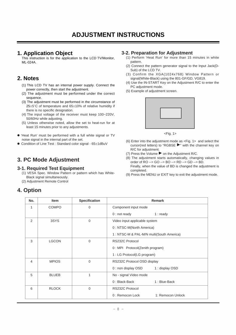
PC adjustment mode.(5) Example of adjustment screen.
(6) Enter into the adjustment mode as <Fig. 1> and select thecursor(red letters) to “RGBSE G” with the channel key onR/C for adjustment.
(7) Press the Volume G on the Adjustment R/C.(8) The adjustment starts automatically, changing values in
order of RO --> GO --> BO --> RD --> GD --> BD.Finally, when the value of BD is changed the adjustment iscompleted.
(9) Press the MENU or EXIT key to exit the adjustment mode.
4. Option
No.
1
2
3
4
5
6
COMPO
3SYS
LGCON
MPIOS
BLUEB
RLOCK
0
0
0
0
1
0
Component input mode
0 : not ready 1 : ready
Video input applicable system
0 : NTSC-M(North America)
1 : NTSC-M & PAL-M/N multi(South America)
RS232C Protocol
0 : MPI Protocol(Zenith program)
1 : LG Protocol(LG program)
RS232C Protocol OSD display
0 : non display OSD 1 : display OSD
No - signal Video mode
0 : Black-Back 1 : Blue-Back
RS232C Protocol
0 : Remocon Lock 1: Remocon Unlock
Item Specification Remark
<Fig. 1>

- 9 -
ADJUSTMENT INSTRUCTIONS
5. RS232C(RMS Only)(1) Use the Untwisted 232C Cable(2) Use the PC program which is sent by Zenith(3) 232C Protocol
No.
1
2
3
4
5
6
7
8
9
10
Power On
Power Off
Volume Up
Volume Down
Volume Direct Access
Set Volume Limit
Direct Channel
Select
Poll/Front Panel
Lockout
Poll/Front Panel
Unlockout
Status Read Back
E110F1
E111F2
E10AEB
E10BEC
EAXXYY
EBXXYY
E4XXYY
A0A0
B0B0
ABWWXXYY
Turn the set on.
Turn the set off.
Volume up 1 level
Volume down 1 level
Select desired volume data directly.
XX : desired volume value(HEX)
YY : check Sum of EA and XX
Set the range of adjustable volume value
XX : adjustment data of volume value
YY : check Sum of E1 and XX
Select channel with number keys.
E4 : Direct Channel command
XX : channel data want to change
YY : check Sum of E4 and XX
Front/Remocon Key Lock command
A0 : Key Lock command(Both Local and Remocon keys)
A0 ; Check Sum
Front/Remocon Key Lock command
B0 : Key Unlock command(Both Local and Remocon keys)
B0 : Check Sum
Read present status of set
Data Bytel(XX)
Bit Description
0~5 Volume data(hex. 0~3F)
6 signal status(1=Good, 0=Bad)
7 Power status(1=On, 0=Off)
Data Byte2(YY)
Bit Description
0~7 Channel Number
(Same with direct Channel)
Command Remark

- 10 -
BLOCK DIAGRAM

- 11 -
NOTES
- 12 -
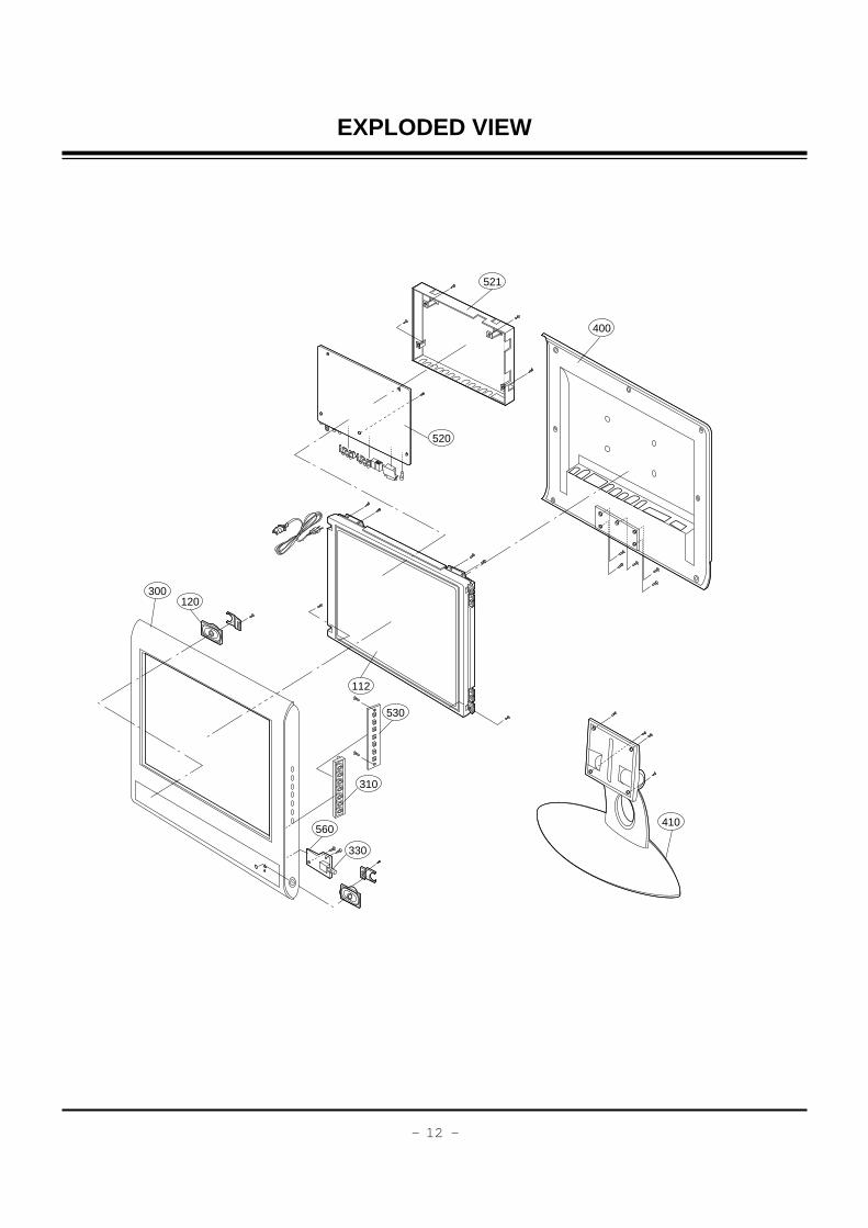
EXPLODED VIEW
300120
112
520
521
400
410
530
310
560
330

- 13 -
EXPLODED VIEW PARTS LIST
112 6306V15002A LCD MODULE,M150X3-L04 XGA CHIMEI TFT COLOR
120 6400VA0017A SPEAKER,GENERAL T401SX-095K14 LG C&D 8 OHM 1.0/1.5W 81DB
300 3091V00443P CABINET ASSEMBLY,RM-15LA54 STEREO ML024A SKD CMO
310 5020V00552J BUTTON,CONTROL RU-15LA51 ABS, HF-380 7KEY
330 5020V00553G BUTTON,POWER RU-15LA51 ABS, HF-380 7KEY
400 3809V00300K BACK COVER ASSEMBLY,RU-15LA50 NON SKD CANADA
410 4811V00029Q BRACKET ASSEMBLY,STAND RM-15LA54 ML024A SKD
430 4814V00269A SHIELD,15LA32 NON METAL NON
520 6871VMMR21A PCB ASSEMBLY,MAIN ML-024A RM-15LA54 PCB ASSY MAIN
521 4950V00095B METAL,MAIN BRACKET SECC ML024A
530 6871VSMA12A PCB ASSEMBLY,SUB CONT MF-004A CTL ASSY RT-15LA30
560 6871VSMU71B PCB ASSEMBLY,SUB POWER ML024A RU-15LA50 POWER ASSY SKD
No. PART NO. DESCRIPTION

- 14 -
REPLACEMENT PARTS LIST
LOCA. NO PART NO DESCRIPTION
Q406
Q502
Q51
Q510
Q52
Q53
Q55
Q56
Q57
Q651
Q701
Q702
Q703
Q704
Q705
Q801
Q802
D100
D51
D52
D53
D54
D55
D56
D57
D601
D602
D701
D702
D703
D704
D706
D707
D709
LED1
ZD202
ZD203
ZD400
ZD701
ZD702
ZD703
C10
C101
C113
0TR387500AA
0TR150400BA
0TRKE80021A
0TR150400BA
0TRKE80021A
0TFVI80034A
0TR387500AA
0TR387500AA
0TR387500AA
0TR150400BA
0TR387500AA
0TR150400BA
0TR387500AA
0TFFC10007A
0TR387500AA
0TR387500AA
0TR150400BA
0DD181009AB
0DD181009AB
0DD181009AB
0DD181009AB
0DD181009AB
0DRDI00028B
0DRDI00028B
0DD181009AB
0DD181009AB
0DD181009AB
0DB260000AA
0DD100009AM
0DD140009AA
0DD100009AM
0DR060009AA
0DRSD00091A
0DRSD00091A
0DL200000CA
0DZRM00178A
0DZRM00178A
0DZ330009BA
0DZ180009AG
0DZ150009AD
0DZ820009AH
0CE227DF618
0CE107BF618
0CE107BF618
CHIP 2SC3875S(ALY) KEC
CHIP 2SA1504S(ASY) KEC
KTC5103D KEC R/TP DPAK 60V 5A
CHIP 2SA1504S(ASY) KEC
KTC5103D KEC R/TP DPAK 60V 5A
SUD45P0315 TO252 30V 13A
CHIP 2SC3875S(ALY) KEC
CHIP 2SC3875S(ALY) KEC
CHIP 2SC3875S(ALY) KEC
CHIP 2SA1504S(ASY) KEC
CHIP 2SC3875S(ALY) KEC
CHIP 2SA1504S(ASY) KEC
CHIP 2SC3875S(ALY) KEC
FQPF12N60 TO220 600V 10.5A
CHIP 2SC3875S(ALY) KEC
CHIP 2SC3875S(ALY) KEC
CHIP 2SA1504S(ASY) KEC
KDS181 TP KEC 85V 300MA
KDS181 TP KEC 85V 300MA
KDS181 TP KEC 85V 300MA
KDS181 TP KEC 85V 300MA
KDS181 TP KEC 85V 300MA
B350A DIODES R/TP SMA 35V 3A
B350A DIODES R/TP SMA 35V 3A
KDS181 TP KEC 85V 300MA
KDS181 TP KEC 85V 300MA
KDS181 TP KEC 85V 300MA
G2SBA60 BK G.I 600V 1.5A 60A 5UA
EU1ZV(1) TP SANKEN
EK14 V(1) 40V 1.5A 40A 0.2US 5MA
EU1ZV(1) TP SANKEN
TVR06J DO41 600V 0.6A
SF20JC10 FTO220(4115) 100V
SF20JC10 FTO220(4115) 100V
LED,SAM5670(DL2LRG) BK YGREEN
ZENERS,UDZS TE17 5.1B
ZENERS,UDZS TE17 5.1B
ZENERS,HZT33
ZENERS,MTZJ18B
ZENERS,MTZJ15B
ZENERS,MTZJ8.2B
220UF STD 16V M
100UF KME 16V M
100UF KME 16V M
LOCA. NO PART NO DESCRIPTION
IC1
IC100
IC101
IC102
IC301
IC351
IC352
IC501
IC502
IC51
IC52
IC53
IC601
IC602
IC603
IC604
IC701
IC702
IC703
IC704
IC707
IC708
IC709
IC710
IC801
IC901
PC1
PC2
Q101
Q102
Q54
IC2
IC705
IC706
Q1
Q100
Q1101
Q1102
Q1103
Q200
Q201
Q202
Q353
Q403
0IMCRTH001A
0IZZVC0101A
0IAL241610B
0IFA752700A
0IMCRMI006A
0IMCRFA010A
0ISO204000A
0IMCRTW001B
0ICTMMO004A
0ITK118100B
0IMCRRH005A
0IMCRRH005A
0IMCRMN014A
0ISA428200A
0IKE704200J
0IMCRFA009A
0IMCRFA017A
0IMCRFA007A
0IMCRFA016A
0IKE780500P
0IMCRKE006B
0IKE780500Q
0IKE780500Q
0IMCRKE006B
0IMCRAD002A
0IAL242110A
0ILI817000G
0ILI817000G
0IFA270000A
0IFA270000A
0IMCRRH004A
0TF492509AA
0TF492509AA
0TF492509AA
0TR387500AA
0TR387500AA
0TR387500AA
0TR387500AA
0TR387500AA
0TR387500AA
0TR387500AA
0TR387500AA
0TR150400BA
0TR150400BA
THC63LVDM83R 56P TRANSMITTER IC
M37272E8A(OTP) DIP 52P DIP
AT24C16A10PI2.7 8PIN DIP ST EEPROM NON
KA75270Z 3 TP RESET IC MC007
M52758FP MITSUBISHI 36PIN
KA7809R 2P DPAK, R/TP REGULATOR IC
CXA2040AQ 32P IIC BUS VIDEO S/W
LG8801H 160P SCALER+VIDEO DECO
SC786108DWR2 16 R/TP OSD
TK11840L 8P SOT23L DCDC CONVERTER
UM6K1N 6P SOT363 R/TP 30V 0.1A
UM6K1N 6P SOT363 R/TP 30V 0.1A
MSP3440G QA B8 V3 80 SOUND IC
LA4282 12S 2CHX10W AUDIO AMP
KIA7042AF SOT89 TP 4.2V
KA78M08RTM 2P DPAK
KA3883C 8 SOP R/TP SMPS CONTROLLER
KA431Z 3DIP,TO92 TP SHUNT
KA78RH33 2P DPAK R/TP 800MA
KIA78L05BP(AT) 3P 5V,150MA
KIA278R33PI TO220IS 4P ST 3.3V
KIA7805API 3P TO220 ST REGULATOR 5V
KIA7805API 3P TO220 ST REGULATOR 5V
KIA278R33PI TO220IS 4P ST 3.3V
AD9883A 80P DIGITAL BOARD
AT24C2110SI2.5 8P,SOP TP 1K EEPROM
LTV817MVB 4P,DIP BK PHOTO COUPLER
LTV817MVB 4P,DIP BK PHOTO COUPLER
2N7000TA TO92, 3P 60V/0.2A,MC007A
2N7000TA TO92, 3P 60V/0.2A,MC007A
UMY1N 5P SOT353 R/TP DUAL SWITCHING
SI4925DY TP TEMIC 30V 6.1A SO8
SI4925DY TP TEMIC 30V 6.1A SO8
SI4925DY TP TEMIC 30V 6.1A SO8
CHIP 2SC3875S(ALY) KEC
CHIP 2SC3875S(ALY) KEC
CHIP 2SC3875S(ALY) KEC
CHIP 2SC3875S(ALY) KEC
CHIP 2SC3875S(ALY) KEC
CHIP 2SC3875S(ALY) KEC
CHIP 2SC3875S(ALY) KEC
CHIP 2SC3875S(ALY) KEC
CHIP 2SA1504S(ASY) KEC
CHIP 2SA1504S(ASY) KEC
IC
TRANSISTOR
RUN DATE : 2003.8.20
For Capacitor & Resistors, thecharactors at 2nd and 3rd digitin the P/No. means as follows;
CC, CX, CK, CN : CeramicCQ : PolyestorCE : Electrolytic
RD : Carbon FilmRS : Metal Oxide FilmRN : Metal FilmRF : Fusible
DIODE
CAPACITOR

- 15 -
LOCA. NO PART NO DESCRIPTION
C128
C13
C209
C211
C215
C216
C289
C302
C315
C317
C331
C351
C353
C354
C356
C357
C362
C364
C380
C381
C403
C404
C408
C412
C499
C501
C51
C523
C526
C541
C55
C581
C60
C601
C602
C605
C613
C614
C616
C617
C62
C620
C621
C626
C627
C629
C633
C643
C646
C647
C648
0CE227BH618
0CE227DF618
0CE476DF618
0CE106DF618
0CE106DF618
0CE106DF618
0CE104DK618
0CE476DF618
0CE476DF618
0CE476DF618
0CE107DF618
0CE227DF618
0CE475DK618
0CE476DF618
0CE106DF618
0CE106DF618
0CE107DF618
0CE336DF618
0CE105DK618
0CE106DF618
0CE476DH618
0CE108DD618
0CE106DK618
0CE105DK618
0CE476DF618
0CE107DF618
0CF2241N5AA
0CE104DK618
0CE107DF618
0CE107DF618
0CF2241N5AA
0CE107DF618
0CK105DF64A
0CE477BF618
0CE477BF618
0CE107BF618
0CE106DF618
0CE106DF618
0CE107DF618
0CE107BF618
0CK105DF64A
0CE335DK618
0CE107BF618
0CK224DF56A
0CK224DF56A
0CE107DF618
0CE107DF618
0CE476BF618
0CE225DK618
0CE225BK618
0CQ1031N509
220UF KME 25V M
220UF STD 16V M
47UF STD 16V M
10UF STD 16V M
10UF STD 16V M
10UF STD 16V M
0.1000UF STD 50V M
47UF STD 16V M
47UF STD 16V M
47UF STD 16V M
100UF STD 16V M
220UF STD 16V M
4.7UF STD 50V 20%
47UF STD 16V M
10UF STD 16V M
10UF STD 16V M
100UF STD 16V M
33UF STD 16V M
1UF STD 50V M
10UF STD 16V M
47UF STD 25V 20%
1000UF STD 10V M
10UF STD 50V M
1UF STD 50V M
47UF STD 16V M
100UF STD 16V M
0.22UF D 100V 10%
0.1000UF STD 50V M
100UF STD 16V M
100UF STD 16V M
0.22UF D 100V 10%
100UF STD 16V M
1UF 2012 16V 20%
470UF KME 16V M
470UF KME 16V M
100UF KME 16V M
10UF STD 16V M
10UF STD 16V M
100UF STD 16V M
100UF KME 16V M
1UF 2012 16V 20%
3.3UF STD 50V 20%
100UF KME 16V M
220000PF 2012 16V 10%
220000PF 2012 16V 10%
100UF STD 16V M
100UF STD 16V M
47UF KME TYPE 16V 20%
2.2UF STD 50V 20%
2.2UF KME TYPE 50V 20%
0.01U 100V K
LOCA. NO PART NO DESCRIPTION
C649
C651
C652
C654
C67
C69
C698
C699
C700
C701
C702
C703
C704
C706
C707
C708
C709
C717
C718
C719
C720
C721
C722
C723
C725
C726
C730
C731
C732
C733
C734
C735
C736
C777
C799
C810
C832
JA201
RJ201
RJ202
L401
L51
L52
T51
T52
0CQ1031N509
0CE107BH618
0CE107BF618
0CE476BF618
0CE337ZF638
0CE107BH618
0CK224DF56A
0CK224DF56A
181-091D
0CF474285B0
0CF334285B0
181-120N
181-120N
0CE476BK618
0CE1272U610
181-091D
181-091U
181-091D
181-091D
0CE227DK618
181-091D
0CE4772J618
0CE477BF618
0CE477BF618
0CE4772J618
0CE477BF618
0CE4772J618
0CE477BF618
0CE4772J618
181-120K
0CE4772J618
0CE477BF618
0CE4772J618
181-091D
0CE107BF618
0CK823DK56A
0CE107DF618
6612VCH003B
6613V00008F
6612VJH008D
0LA0272K139
6140VR0004A
6140VR0004A
6170VH0001A
6170VH0001A
0.01U 100V K
100UF KME 25V M
100UF KME 16V M
47UF KME TYPE 16V 20%
330UF SEP 16V 20%
100UF KME 25V M
220000PF 2012 16V 10%
220000PF 2012 16V 10%
DEHR33A102KN2A 1000PF 1KV 10%,10%
0.47UF S 275V 10%
0.33UF S 275V 10%
1000PF 4KV M E
1000PF 4KV M E
47UF KME 50V M
120UF KMF 400V 20%
DEHR33A102KN2A 1000PF 1KV 10%,10%
R 220PF 2KV 10%,10%
DEHR33A102KN2A 1000PF 1KV 10%,10%
DEHR33A102KN2A 1000PF 1KV 10%,10%
220UF STD 50V M
DEHR33A102KN2A 1000PF 1KV 10%,10%
470UF KMF 35V 20%
470UF KME 16V M
470UF KME 16V M
470UF KMF 35V 20%
470UF KME 16V M
470UF KMF 35V 20%
470UF KME 16V M
470UF KMF 35V 20%
2200PF 4KV M E
470UF KMF 35V 20%
470UF KME 16V M
470UF KMF 35V 20%
DEHR33A102KN2A 1000PF 1KV 10%,10%
100UF KME 16V M
82000PF 2012 50V 10%
100UF STD 16V M
JACK,PHONE PEJ012C H=6.5 STEREO 1P
JACK ASSY,PMJ014F E/P(ST)+SVHS+3P
JACK,RCA PJ6063D DVD IN 3P
INDUCTOR,27UH K
COIL,TOKO B953AS330M=P3, 33UH
COIL,TOKO B953AS330M=P3, 33UH
TRANSFORMER,INVERTER 969HGK003 8.985UH
TRANSFORMER,INVERTER 969HGK003 8.985UH
REPLACEMENT PARTS LIST
JACK
COIL & TRANSFORMER

- 16 -
LOCA. NO PART NO DESCRIPTION
T701
FR704
L502
L503
L504
L505
L506
L507
L518
R200
R201
R51
R54
R69
R70
R701
R702
R703
R704
R705
R707
R71
R711
R712
R715
R727
R728
SW1101
SW1101
SW1102
SW1103
SW1104
SW1105
SW1106
SW1107
L1
L101
L102
L119
L200
L201
L202
L204
L205
L206
6170VMCA47A
0RP0020J809
0RRZVTA001A
0RRZVTA001A
0RRZVTA001A
0RRZVTA001A
0RRZVTA001A
0RRZVTA001A
0RRZVTA001A
0RD1000H609
0RD1000H609
0RS6800J607
0RS6800J607
0RN1302F409
0RN4701F409
0RS5602K619
0RKZVTA001C
0RKZVTA001K
0RS5602K619
0RS5602K619
0RD3303H609
0RN4701F409
0RS5602K619
0RD6803H609
180-A01R
0RD0472H609
0RD0472H609
140-275B
140-313A
140-313A
140-313A
140-313A
140-313A
140-313A
140-313A
6210TCE001G
6210TCE001G
6210TCE001G
6210TCE001A
6210TCE001A
6210TCE001A
6210TCE001A
6210TCE001A
6210TCE001A
6210TCE001G
TRANSFORMER,SMPS[COIL] EER3016 510UH
0.02 OHM 1 W 20%
MNR14E0AJ101 R OHM 100 OHM 5%
MNR14E0AJ101 R OHM 100 OHM 5%
MNR14E0AJ101 R OHM 100 OHM 5%
MNR14E0AJ101 R OHM 100 OHM 5%
MNR14E0AJ101 R OHM 100 OHM 5%
MNR14E0AJ101 R OHM 100 OHM 5%
MNR14E0AJ101 R OHM 100 OHM 5%
100 OHM 1/2 W 5.00%
100 OHM 1/2 W 5.00%
680 OHM 1 W 5.00%
680 OHM 1 W 5.00%
13K OHM 1/6 W 1.00%
4.7K OHM 1/6 W 1.00%
56K OHM 2 W 5.00%
8.2M OHM 1/2 W 5%
0.47M OHM 1/2 W 5%
56K OHM 2 W 5.00%
56K OHM 2 W 5.00%
330K OHM 1/2 W 5.00%
4.7K OHM 1/6 W 1.00%
56K OHM 2 W 5.00%
680K OHM 1/2 W 5.00%
2 W RW ROUND G 0.39
47 OHM 1/2 W 5.00%
47 OHM 1/2 W 5.00%
SWITCH,PUSH JDPB21NA 30V 0.3A
SWITCH,TACT 2LEAD 100G(TA) 5V
SWITCH,TACT 2LEAD 100G(TA) 5V
SWITCH,TACT 2LEAD 100G(TA) 5V
SWITCH,TACT 2LEAD 100G(TA) 5V
SWITCH,TACT 2LEAD 100G(TA) 5V
SWITCH,TACT 2LEAD 100G(TA) 5V
SWITCH,TACT 2LEAD 100G(TA) 5V
FILTER,EMC HH1M3216501
FILTER,EMC HH1M3216501
FILTER,EMC HH1M3216501
FILTER,EMC HB1S2012080JT
FILTER,EMC HB1S2012080JT
FILTER,EMC HB1S2012080JT
FILTER,EMC HB1S2012080JT
FILTER,EMC HB1S2012080JT
FILTER,EMC HB1S2012080JT
FILTER,EMC HH1M3216501
LOCA. NO PART NO DESCRIPTION
L213
L214
L298
L299
L313
L351
L400
L402
L501
L515
L516
L517
L580
L600
L601
L602
L603
L701
L801
L802
L803
L99
LF701
LF702
R505
Z100
Z500
Z600
F701
P1101
P701
P900
PA1101
TH701
TU401
VA701
A1
A2
A3
A4
A5
6210TCE001G
6210TCE001G
6210TCE001A
6210TCE001A
6210TCE001G
6210TCE001G
6210TCE001G
6210TCE001G
6210TCE001G
6210TCE001G
6210VC0004A
6210TCE001G
6210TCE001A
6210TCE001G
6210TCE001G
6210TCE001G
6210TCE001G
125-022K
6210TCE001G
6210TCE001G
6210TCE001G
6210TCE001G
6200JB8010U
6200JB8010U
6210TCE001A
156-A01L
156-A02X
156-A02M
0FS3151B51D
6631V20014E
6620VZ0002A
6630G15E215
6726VV0006D
163-048D
6700VNF019E
164-003K
3828VA0359T
6710V00082M
6410VUH007A
6851V00004D
6866VA9001A
FILTER,EMC HH1M3216501
FILTER,EMC HH1M3216501
FILTER,EMC HB1S2012080JT
FILTER,EMC HB1S2012080JT
FILTER,EMC HH1M3216501
FILTER,EMC HH1M3216501
FILTER,EMC HH1M3216501
FILTER,EMC HH1M3216501
FILTER,EMC HH1M3216501
FILTER,EMC HH1M3216501
FILTER,EMC BK3216 4S600
FILTER,EMC HH1M3216501
FILTER,EMC HB1S2012080JT
FILTER,EMC HH1M3216501
FILTER,EMC HH1M3216501
FILTER,EMC HH1M3216501
FILTER,EMC HH1M3216501
FILTER,EMC FERRITE 1UH
FILTER,EMC HH1M3216501
FILTER,EMC HH1M3216501
FILTER,EMC HH1M3216501
FILTER,EMC HH1M3216501
FILTER,EMC OR 14*7*7.5H 6.0MH11.0MH
FILTER,EMC OR 14*7*7.5H 6.0MH11.0MH
FILTER,EMC HB1S2012080JT
RESONATOR,CRYSTAL HC49U 6.000MHZ
RESONATOR,CRYSTAL HC49U 27.000MHZ
RESONATOR,CRYSTAL HC49U 18.432MHZ
FUSE,SLOW BLOW 3150MA 250V
CONNECTOR ASSEMBLY,12P 2.0MM
SOCKET,DRAWING IS7007 AC SOCKET
CONNECTOR,DSUB 15P 2.29MM
REMOTE CONTROLLER RECEIVER,38.0KHZ
THERMISTOR,KL15L2R5 +/ 15% 125V
TUNER,TAFHH001P LG NTSC FS .
VARISTOR,SVC621D14A 620V 0%
MANUAL,OWNERS RM15LA54 ZENITH
REMOTE CONTROLLER,ML024A W/O TXT
POWER CORD,SP305+IS034 SVT18AWG*3C
CABLE ASSEMBLY,AUDIO TO AUDIO 2000MM
CONNECTOR,DSUB 29909C,AT,L1830
SWITCH
FILTER & CRYSTAL
REPLACEMENT PARTS LIST
RESISTOR
MISCELLANEOUS
ACCESSORIES


JOHN
Nota adhesiva
TK11840L
JOHN
Nota adhesiva
CORTO ENTRE BASE Y EMISOR DE Q57 PARA ANULAR PROTECCIÓN OLP.
JOHN
Nota adhesiva
C51 ó C55 CON FUGAS O EN CORTO, PROVOCAN EL APAGADO DEL CIRCUITO INVERSOR.
yonqui
Nota adhesiva
0.52v/2350OHM=256.45uA (221.27uA) la diferencia con el resultado de calculadora, es el hecho de ser una onda pulsante que también atraviesa un condensador de baja capacitancia. Por tanto se pierde algo en el condensador.
yonqui
Nota adhesiva
14350ohm * 212.8uA =3.053vdc 3.053vdc * √2= 4.3176VDC PULSANTE
yonqui
Nota adhesiva
14350 (suma de resistencias) * 256.45A= 3.68V + 0.7V(DIODO)=4.38VAC 4.38*2√ 2=12.39Vpp 12.39Vpp/1000=12.39mApp
yonqui
Nota adhesiva
Si cada lámpara tiene una resistencia promedio de 50K, entonces para una corriente de 12.39mApp, debemos tener un voltaje de 619.5vPP. Entonces tenemos un vatiaje real de aprox.2.7W en cada lámpara. Este es el vatiaje actual. La lámpara debe tener un vatiaje mayor.

MAIN(TOP) MAIN(BOTTOM)
CONTROL POWER