Service Manual - interest · PRISMA System An integrated system for continuous fluid management,...
342
PRISMA System An integrated system for continuous fluid management, renal replacement therapies and therapeutic plasma exchange For software version R03.10 ® Service Manual GAMBRO DASCO S.p.A. Via Modenese, 66 41036 Medolla (MO) -Italy Reorder Service Code 6983928 Rev. A Manufacturing P/N 9032168000 Rev. A 2006/09
Transcript of Service Manual - interest · PRISMA System An integrated system for continuous fluid management,...

PRISMA SystemAn integrated system for continuous fluid management, renal replacement therapies and therapeutic plasma exchange
For software version R03.10
®
Service Manual
GAMBRO DASCO S.p.A.Via Modenese, 66
41036 Medolla (MO) -Italy
Reorder Service Code 6983928 Rev. AManufacturing P/N 9032168000 Rev. A
2006/09

Manufactured by: GAMBRO DASCO S.p.A., Via Modenese 66, 41036 MEDOLLA (MO) Italy
Questions or comments about this publication can be directed to your local representative or to manufacturer.
© 1992-1996, 1998 Gambro Inc. (unpublished), 2000-2001 Gambro Dasco SpA (unpublished), 2001-2006 Gambro Lundia AB (unpublished)
PRISMA® is a trademark of GAMBRO Inc. registered in the United States, Argentina, Chile, Mexico, and Uruguay.
GAMBRO® is a registered trademark of GAMBRO LUNDIA AB.
HOSPAL® is a registered trademark of GAMBRO HOSPAL SWITZERLAND Ltd.
The PRISMA® machine is protected by one or more of the following patents:
- U.S. patents: 4861242, 5644402, 5722399, 5679245, 5776345, 5910252, 5762805, 5211849, 5394732;
- European patents: 0611228, 0678301, 0701830, 0829265, 0706044, 0607301, 0643301;
- GB patents: 2208897;
- Canadian patents: 1284598, 2115414, 2303714, 2119375;
- Japanese patents: 1772297, 2823513, 3690846, 3591864, 3413412, 3140781;
- German patents: 3828123;
- French patents: 2619604, 2724321, 2725522;
- Italian patents: 1223781.

PRISMA® System Service Manual i
Preface
Indications . . . . . . . . . . . . . . . . . . . . . . . . . . . . . . . . . . . . . . . . . . . . . . . . . . . . xiiiContraindications . . . . . . . . . . . . . . . . . . . . . . . . . . . . . . . . . . . . . . . . . . . . . . xiiiSystem Components . . . . . . . . . . . . . . . . . . . . . . . . . . . . . . . . . . . . . . . . . . . . xiii
Control Unit . . . . . . . . . . . . . . . . . . . . . . . . . . . . . . . . . . . . . . . . . . . . . . . xiiiSet . . . . . . . . . . . . . . . . . . . . . . . . . . . . . . . . . . . . . . . . . . . . . . . . . . . . . . xiii
Where to Find Information About the PRISMA System . . . . . . . . . . . . . . . . xivOperator’s Manual . . . . . . . . . . . . . . . . . . . . . . . . . . . . . . . . . . . . . . . . . xivOn-line Instructions . . . . . . . . . . . . . . . . . . . . . . . . . . . . . . . . . . . . . . . . xivPRISMA Set Instructions for Use . . . . . . . . . . . . . . . . . . . . . . . . . . . . . xiv
Warnings . . . . . . . . . . . . . . . . . . . . . . . . . . . . . . . . . . . . . . . . . . . . . . . . . . . . xivPrecautions . . . . . . . . . . . . . . . . . . . . . . . . . . . . . . . . . . . . . . . . . . . . . . . . . . xixDisclaimer . . . . . . . . . . . . . . . . . . . . . . . . . . . . . . . . . . . . . . . . . . . . . . . . . . . xxiiiService Information . . . . . . . . . . . . . . . . . . . . . . . . . . . . . . . . . . . . . . . . . . . . xxivDisposal of Lithium Energy Cell . . . . . . . . . . . . . . . . . . . . . . . . . . . . . . . . . . xxviDisposal of Packaging Material . . . . . . . . . . . . . . . . . . . . . . . . . . . . . . . . . . . xxviWarranty . . . . . . . . . . . . . . . . . . . . . . . . . . . . . . . . . . . . . . . . . . . . . . . . . . . . xxvi
Chapter 1: Introduction
Introduction . . . . . . . . . . . . . . . . . . . . . . . . . . . . . . . . . . . . . . . . . . . . . . . . . . 1-1Blood Access . . . . . . . . . . . . . . . . . . . . . . . . . . . . . . . . . . . . . . . . . . . . . 1-1PRISMA Control Unit Functions . . . . . . . . . . . . . . . . . . . . . . . . . . . . . . 1-1
Therapy Overview . . . . . . . . . . . . . . . . . . . . . . . . . . . . . . . . . . . . . . . . . . . . . 1-1PRISMA Therapy Options . . . . . . . . . . . . . . . . . . . . . . . . . . . . . . . . . . . 1-2Mechanisms of Therapy . . . . . . . . . . . . . . . . . . . . . . . . . . . . . . . . . . . . 1-2
Ultrafiltration . . . . . . . . . . . . . . . . . . . . . . . . . . . . . . . . . . . . . . . . . . . 1-2Hemofiltration . . . . . . . . . . . . . . . . . . . . . . . . . . . . . . . . . . . . . . . . . . 1-2Hemodialysis . . . . . . . . . . . . . . . . . . . . . . . . . . . . . . . . . . . . . . . . . . 1-2Hemodiafiltration . . . . . . . . . . . . . . . . . . . . . . . . . . . . . . . . . . . . . . . 1-3Therapeutic Plasma Exchange . . . . . . . . . . . . . . . . . . . . . . . . . . . . 1-3
PRISMA Control Unit . . . . . . . . . . . . . . . . . . . . . . . . . . . . . . . . . . . . . . . . . . 1-4Front Panel . . . . . . . . . . . . . . . . . . . . . . . . . . . . . . . . . . . . . . . . . . . . . . 1-4
Status Lights . . . . . . . . . . . . . . . . . . . . . . . . . . . . . . . . . . . . . . . . . . 1-4Display . . . . . . . . . . . . . . . . . . . . . . . . . . . . . . . . . . . . . . . . . . . . . . . 1-5Pressure Sensor Housings . . . . . . . . . . . . . . . . . . . . . . . . . . . . . . . 1-5Peristaltic Pumps . . . . . . . . . . . . . . . . . . . . . . . . . . . . . . . . . . . . . . . 1-5Cartridge Carrier . . . . . . . . . . . . . . . . . . . . . . . . . . . . . . . . . . . . . . . 1-6Blood Pump . . . . . . . . . . . . . . . . . . . . . . . . . . . . . . . . . . . . . . . . . . . 1-6Air Bubble Detector . . . . . . . . . . . . . . . . . . . . . . . . . . . . . . . . . . . . . 1-6Pump Raceway . . . . . . . . . . . . . . . . . . . . . . . . . . . . . . . . . . . . . . . . 1-6Dialysate Pump . . . . . . . . . . . . . . . . . . . . . . . . . . . . . . . . . . . . . . . . 1-6Return Line Clamp . . . . . . . . . . . . . . . . . . . . . . . . . . . . . . . . . . . . . . 1-6Tubing Guides . . . . . . . . . . . . . . . . . . . . . . . . . . . . . . . . . . . . . . . . . 1-6Corner Hooks . . . . . . . . . . . . . . . . . . . . . . . . . . . . . . . . . . . . . . . . . . 1-6Blood Leak Detector . . . . . . . . . . . . . . . . . . . . . . . . . . . . . . . . . . . . . 1-6Syringe Pump Assembly . . . . . . . . . . . . . . . . . . . . . . . . . . . . . . . . . 1-6

ii PRISMA® System Service Manual
Rotor . . . . . . . . . . . . . . . . . . . . . . . . . . . . . . . . . . . . . . . . . . . . . . . . 1-7Effluent Pump . . . . . . . . . . . . . . . . . . . . . . . . . . . . . . . . . . . . . . . . . . 1-7
Bottom Panel . . . . . . . . . . . . . . . . . . . . . . . . . . . . . . . . . . . . . . . . . . . . . 1-7Scales . . . . . . . . . . . . . . . . . . . . . . . . . . . . . . . . . . . . . . . . . . . . . . . 1-7Scale Hook Assemblies . . . . . . . . . . . . . . . . . . . . . . . . . . . . . . . . . . 1-7
Right Side Panel . . . . . . . . . . . . . . . . . . . . . . . . . . . . . . . . . . . . . . . . . . 1-7Power Switch . . . . . . . . . . . . . . . . . . . . . . . . . . . . . . . . . . . . . . . . . . 1-7
Left Side Panel . . . . . . . . . . . . . . . . . . . . . . . . . . . . . . . . . . . . . . . . . . . 1-7Fan . . . . . . . . . . . . . . . . . . . . . . . . . . . . . . . . . . . . . . . . . . . . . . . . . . 1-7
Rear Panel . . . . . . . . . . . . . . . . . . . . . . . . . . . . . . . . . . . . . . . . . . . . . . 1-7Controller CCA . . . . . . . . . . . . . . . . . . . . . . . . . . . . . . . . . . . . . . . . . 1-8Monitor CCA . . . . . . . . . . . . . . . . . . . . . . . . . . . . . . . . . . . . . . . . . . . 1-8Detector CCA . . . . . . . . . . . . . . . . . . . . . . . . . . . . . . . . . . . . . . . . . . 1-8Hour Meter . . . . . . . . . . . . . . . . . . . . . . . . . . . . . . . . . . . . . . . . . . . . 1-9Power Supply . . . . . . . . . . . . . . . . . . . . . . . . . . . . . . . . . . . . . . . . . . 1-9Serial Communication Port . . . . . . . . . . . . . . . . . . . . . . . . . . . . . . . 1-9Power Distribution CCA . . . . . . . . . . . . . . . . . . . . . . . . . . . . . . . . . . 1-9Fuses . . . . . . . . . . . . . . . . . . . . . . . . . . . . . . . . . . . . . . . . . . . . . . . . 1-9Power Entry Module . . . . . . . . . . . . . . . . . . . . . . . . . . . . . . . . . . . . . 1-9Automatic Reposition System (ARPS) . . . . . . . . . . . . . . . . . . . . . . . 1-9Driver CCA . . . . . . . . . . . . . . . . . . . . . . . . . . . . . . . . . . . . . . . . . . . . 1-9Analog CCA . . . . . . . . . . . . . . . . . . . . . . . . . . . . . . . . . . . . . . . . . . . 1-9
Jumpers Configuration . . . . . . . . . . . . . . . . . . . . . . . . . . . . . . . . . . . . 1-10
Chapter 2: Continuous Renal Replacement and Therapeutic Plasma Exchange Therapies
CRRT System Overview . . . . . . . . . . . . . . . . . . . . . . . . . . . . . . . . . . . . . . . . 2-3Interactive Display . . . . . . . . . . . . . . . . . . . . . . . . . . . . . . . . . . . . . . 2-4User-controllable Settings . . . . . . . . . . . . . . . . . . . . . . . . . . . . . . . . 2-4
Default Values . . . . . . . . . . . . . . . . . . . . . . . . . . . . . . . . . . . . . 2-4Current Values . . . . . . . . . . . . . . . . . . . . . . . . . . . . . . . . . . . . . 2-5
Pumps . . . . . . . . . . . . . . . . . . . . . . . . . . . . . . . . . . . . . . . . . . . . . . . . . . 2-5Flow Rates and Anticoagulant Settings . . . . . . . . . . . . . . . . . . . . . . . . . 2-5
Adjusting the Flow Rates and Anticoagulant Settings . . . . . . . . . . . 2-6Patient Fluid Removal Rate . . . . . . . . . . . . . . . . . . . . . . . . . . . . . . . 2-6
Calculating the Desired Patient Fluid Removal Rate . . . . . . . . 2-6Adjusting the Patient Fluid Removal Rate . . . . . . . . . . . . . . . . 2-6Machine Control of Patient Fluid Removal Rate . . . . . . . . . . . 2-7Setting the "Excess Pt. Fluid Loss or Gain" Safety Limit . . . . . 2-7
Fluid Balance . . . . . . . . . . . . . . . . . . . . . . . . . . . . . . . . . . . . . . . . . . . . . 2-7Actual Patient Fluid Removed . . . . . . . . . . . . . . . . . . . . . . . . . . . . . 2-7
Measuring Actual Patient Fluid Removed . . . . . . . . . . . . . . . . 2-7Viewing Actual Patient Fluid Removed . . . . . . . . . . . . . . . . . . 2-8
I/O Data . . . . . . . . . . . . . . . . . . . . . . . . . . . . . . . . . . . . . . . . . . . . . . 2-8Treatment History Data . . . . . . . . . . . . . . . . . . . . . . . . . . . . . . . . . . . . . 2-9
I/O History . . . . . . . . . . . . . . . . . . . . . . . . . . . . . . . . . . . . . . . . . . . . 2-9Events History . . . . . . . . . . . . . . . . . . . . . . . . . . . . . . . . . . . . . . . . . 2-9History Data After a Treatment . . . . . . . . . . . . . . . . . . . . . . . . . . . 2-10History Data During a Power Loss . . . . . . . . . . . . . . . . . . . . . . . . . 2-10
Alarm Safety System . . . . . . . . . . . . . . . . . . . . . . . . . . . . . . . . . . . . . . 2-10Monitoring Systems . . . . . . . . . . . . . . . . . . . . . . . . . . . . . . . . . . . . . . . 2-10
Pressure . . . . . . . . . . . . . . . . . . . . . . . . . . . . . . . . . . . . . . . . . . . . . 2-10
PRISMA® System Service Manual iii
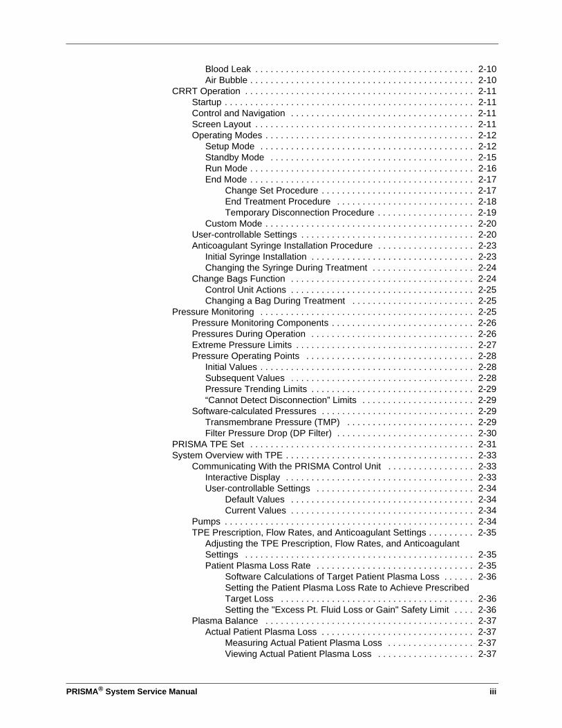
Blood Leak . . . . . . . . . . . . . . . . . . . . . . . . . . . . . . . . . . . . . . . . . . . 2-10Air Bubble . . . . . . . . . . . . . . . . . . . . . . . . . . . . . . . . . . . . . . . . . . . . 2-10
CRRT Operation . . . . . . . . . . . . . . . . . . . . . . . . . . . . . . . . . . . . . . . . . . . . . 2-11Startup . . . . . . . . . . . . . . . . . . . . . . . . . . . . . . . . . . . . . . . . . . . . . . . . . 2-11Control and Navigation . . . . . . . . . . . . . . . . . . . . . . . . . . . . . . . . . . . . 2-11Screen Layout . . . . . . . . . . . . . . . . . . . . . . . . . . . . . . . . . . . . . . . . . . . 2-11Operating Modes . . . . . . . . . . . . . . . . . . . . . . . . . . . . . . . . . . . . . . . . . 2-12
Setup Mode . . . . . . . . . . . . . . . . . . . . . . . . . . . . . . . . . . . . . . . . . . 2-12Standby Mode . . . . . . . . . . . . . . . . . . . . . . . . . . . . . . . . . . . . . . . . 2-15Run Mode . . . . . . . . . . . . . . . . . . . . . . . . . . . . . . . . . . . . . . . . . . . . 2-16End Mode . . . . . . . . . . . . . . . . . . . . . . . . . . . . . . . . . . . . . . . . . . . . 2-17
Change Set Procedure . . . . . . . . . . . . . . . . . . . . . . . . . . . . . . 2-17End Treatment Procedure . . . . . . . . . . . . . . . . . . . . . . . . . . . 2-18Temporary Disconnection Procedure . . . . . . . . . . . . . . . . . . . 2-19
Custom Mode . . . . . . . . . . . . . . . . . . . . . . . . . . . . . . . . . . . . . . . . . 2-20User-controllable Settings . . . . . . . . . . . . . . . . . . . . . . . . . . . . . . . . . . 2-20Anticoagulant Syringe Installation Procedure . . . . . . . . . . . . . . . . . . . 2-23
Initial Syringe Installation . . . . . . . . . . . . . . . . . . . . . . . . . . . . . . . . 2-23Changing the Syringe During Treatment . . . . . . . . . . . . . . . . . . . . 2-24
Change Bags Function . . . . . . . . . . . . . . . . . . . . . . . . . . . . . . . . . . . . 2-24Control Unit Actions . . . . . . . . . . . . . . . . . . . . . . . . . . . . . . . . . . . . 2-25Changing a Bag During Treatment . . . . . . . . . . . . . . . . . . . . . . . . 2-25
Pressure Monitoring . . . . . . . . . . . . . . . . . . . . . . . . . . . . . . . . . . . . . . . . . . 2-25Pressure Monitoring Components . . . . . . . . . . . . . . . . . . . . . . . . . . . . 2-26Pressures During Operation . . . . . . . . . . . . . . . . . . . . . . . . . . . . . . . . 2-26Extreme Pressure Limits . . . . . . . . . . . . . . . . . . . . . . . . . . . . . . . . . . . 2-27Pressure Operating Points . . . . . . . . . . . . . . . . . . . . . . . . . . . . . . . . . 2-28
Initial Values . . . . . . . . . . . . . . . . . . . . . . . . . . . . . . . . . . . . . . . . . . 2-28Subsequent Values . . . . . . . . . . . . . . . . . . . . . . . . . . . . . . . . . . . . 2-28Pressure Trending Limits . . . . . . . . . . . . . . . . . . . . . . . . . . . . . . . . 2-29“Cannot Detect Disconnection” Limits . . . . . . . . . . . . . . . . . . . . . . 2-29
Software-calculated Pressures . . . . . . . . . . . . . . . . . . . . . . . . . . . . . . 2-29Transmembrane Pressure (TMP) . . . . . . . . . . . . . . . . . . . . . . . . . 2-29Filter Pressure Drop (DP Filter) . . . . . . . . . . . . . . . . . . . . . . . . . . . 2-30
PRISMA TPE Set . . . . . . . . . . . . . . . . . . . . . . . . . . . . . . . . . . . . . . . . . . . . 2-31System Overview with TPE . . . . . . . . . . . . . . . . . . . . . . . . . . . . . . . . . . . . . 2-33
Communicating With the PRISMA Control Unit . . . . . . . . . . . . . . . . . 2-33Interactive Display . . . . . . . . . . . . . . . . . . . . . . . . . . . . . . . . . . . . . 2-33User-controllable Settings . . . . . . . . . . . . . . . . . . . . . . . . . . . . . . . 2-34
Default Values . . . . . . . . . . . . . . . . . . . . . . . . . . . . . . . . . . . . 2-34Current Values . . . . . . . . . . . . . . . . . . . . . . . . . . . . . . . . . . . . 2-34
Pumps . . . . . . . . . . . . . . . . . . . . . . . . . . . . . . . . . . . . . . . . . . . . . . . . . 2-34TPE Prescription, Flow Rates, and Anticoagulant Settings . . . . . . . . . 2-35
Adjusting the TPE Prescription, Flow Rates, and Anticoagulant Settings . . . . . . . . . . . . . . . . . . . . . . . . . . . . . . . . . . . . . . . . . . . . . 2-35Patient Plasma Loss Rate . . . . . . . . . . . . . . . . . . . . . . . . . . . . . . . 2-35
Software Calculations of Target Patient Plasma Loss . . . . . . 2-36Setting the Patient Plasma Loss Rate to Achieve Prescribed Target Loss . . . . . . . . . . . . . . . . . . . . . . . . . . . . . . . . . . . . . . 2-36Setting the "Excess Pt. Fluid Loss or Gain" Safety Limit . . . . 2-36
Plasma Balance . . . . . . . . . . . . . . . . . . . . . . . . . . . . . . . . . . . . . . . . . 2-37Actual Patient Plasma Loss . . . . . . . . . . . . . . . . . . . . . . . . . . . . . . 2-37
Measuring Actual Patient Plasma Loss . . . . . . . . . . . . . . . . . 2-37Viewing Actual Patient Plasma Loss . . . . . . . . . . . . . . . . . . . 2-37
iv PRISMA® System Service Manual
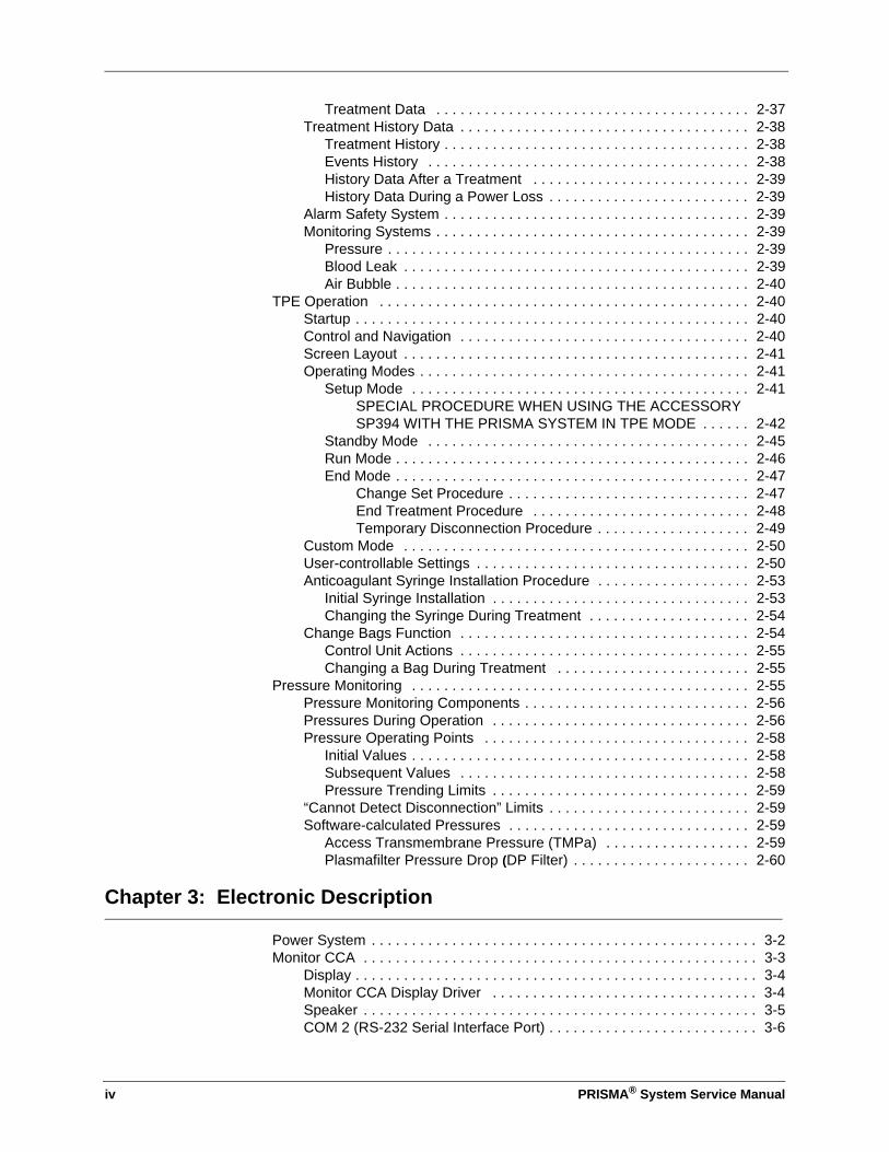
Treatment Data . . . . . . . . . . . . . . . . . . . . . . . . . . . . . . . . . . . . . . . 2-37Treatment History Data . . . . . . . . . . . . . . . . . . . . . . . . . . . . . . . . . . . . 2-38
Treatment History . . . . . . . . . . . . . . . . . . . . . . . . . . . . . . . . . . . . . . 2-38Events History . . . . . . . . . . . . . . . . . . . . . . . . . . . . . . . . . . . . . . . . 2-38History Data After a Treatment . . . . . . . . . . . . . . . . . . . . . . . . . . . 2-39History Data During a Power Loss . . . . . . . . . . . . . . . . . . . . . . . . . 2-39
Alarm Safety System . . . . . . . . . . . . . . . . . . . . . . . . . . . . . . . . . . . . . . 2-39Monitoring Systems . . . . . . . . . . . . . . . . . . . . . . . . . . . . . . . . . . . . . . . 2-39
Pressure . . . . . . . . . . . . . . . . . . . . . . . . . . . . . . . . . . . . . . . . . . . . . 2-39Blood Leak . . . . . . . . . . . . . . . . . . . . . . . . . . . . . . . . . . . . . . . . . . . 2-39Air Bubble . . . . . . . . . . . . . . . . . . . . . . . . . . . . . . . . . . . . . . . . . . . . 2-40
TPE Operation . . . . . . . . . . . . . . . . . . . . . . . . . . . . . . . . . . . . . . . . . . . . . . 2-40Startup . . . . . . . . . . . . . . . . . . . . . . . . . . . . . . . . . . . . . . . . . . . . . . . . . 2-40Control and Navigation . . . . . . . . . . . . . . . . . . . . . . . . . . . . . . . . . . . . 2-40Screen Layout . . . . . . . . . . . . . . . . . . . . . . . . . . . . . . . . . . . . . . . . . . . 2-41Operating Modes . . . . . . . . . . . . . . . . . . . . . . . . . . . . . . . . . . . . . . . . . 2-41
Setup Mode . . . . . . . . . . . . . . . . . . . . . . . . . . . . . . . . . . . . . . . . . . 2-41SPECIAL PROCEDURE WHEN USING THE ACCESSORY SP394 WITH THE PRISMA SYSTEM IN TPE MODE . . . . . . 2-42
Standby Mode . . . . . . . . . . . . . . . . . . . . . . . . . . . . . . . . . . . . . . . . 2-45Run Mode . . . . . . . . . . . . . . . . . . . . . . . . . . . . . . . . . . . . . . . . . . . . 2-46End Mode . . . . . . . . . . . . . . . . . . . . . . . . . . . . . . . . . . . . . . . . . . . . 2-47
Change Set Procedure . . . . . . . . . . . . . . . . . . . . . . . . . . . . . . 2-47End Treatment Procedure . . . . . . . . . . . . . . . . . . . . . . . . . . . 2-48Temporary Disconnection Procedure . . . . . . . . . . . . . . . . . . . 2-49
Custom Mode . . . . . . . . . . . . . . . . . . . . . . . . . . . . . . . . . . . . . . . . . . . 2-50User-controllable Settings . . . . . . . . . . . . . . . . . . . . . . . . . . . . . . . . . . 2-50Anticoagulant Syringe Installation Procedure . . . . . . . . . . . . . . . . . . . 2-53
Initial Syringe Installation . . . . . . . . . . . . . . . . . . . . . . . . . . . . . . . . 2-53Changing the Syringe During Treatment . . . . . . . . . . . . . . . . . . . . 2-54
Change Bags Function . . . . . . . . . . . . . . . . . . . . . . . . . . . . . . . . . . . . 2-54Control Unit Actions . . . . . . . . . . . . . . . . . . . . . . . . . . . . . . . . . . . . 2-55Changing a Bag During Treatment . . . . . . . . . . . . . . . . . . . . . . . . 2-55
Pressure Monitoring . . . . . . . . . . . . . . . . . . . . . . . . . . . . . . . . . . . . . . . . . . 2-55Pressure Monitoring Components . . . . . . . . . . . . . . . . . . . . . . . . . . . . 2-56Pressures During Operation . . . . . . . . . . . . . . . . . . . . . . . . . . . . . . . . 2-56Pressure Operating Points . . . . . . . . . . . . . . . . . . . . . . . . . . . . . . . . . 2-58
Initial Values . . . . . . . . . . . . . . . . . . . . . . . . . . . . . . . . . . . . . . . . . . 2-58Subsequent Values . . . . . . . . . . . . . . . . . . . . . . . . . . . . . . . . . . . . 2-58Pressure Trending Limits . . . . . . . . . . . . . . . . . . . . . . . . . . . . . . . . 2-59
“Cannot Detect Disconnection” Limits . . . . . . . . . . . . . . . . . . . . . . . . . 2-59Software-calculated Pressures . . . . . . . . . . . . . . . . . . . . . . . . . . . . . . 2-59
Access Transmembrane Pressure (TMPa) . . . . . . . . . . . . . . . . . . 2-59Plasmafilter Pressure Drop (DP Filter) . . . . . . . . . . . . . . . . . . . . . . 2-60
Chapter 3: Electronic Description
Power System . . . . . . . . . . . . . . . . . . . . . . . . . . . . . . . . . . . . . . . . . . . . . . . . 3-2Monitor CCA . . . . . . . . . . . . . . . . . . . . . . . . . . . . . . . . . . . . . . . . . . . . . . . . . 3-3
Display . . . . . . . . . . . . . . . . . . . . . . . . . . . . . . . . . . . . . . . . . . . . . . . . . . 3-4Monitor CCA Display Driver . . . . . . . . . . . . . . . . . . . . . . . . . . . . . . . . . 3-4Speaker . . . . . . . . . . . . . . . . . . . . . . . . . . . . . . . . . . . . . . . . . . . . . . . . . 3-5COM 2 (RS-232 Serial Interface Port) . . . . . . . . . . . . . . . . . . . . . . . . . . 3-6
PRISMA® System Service Manual v
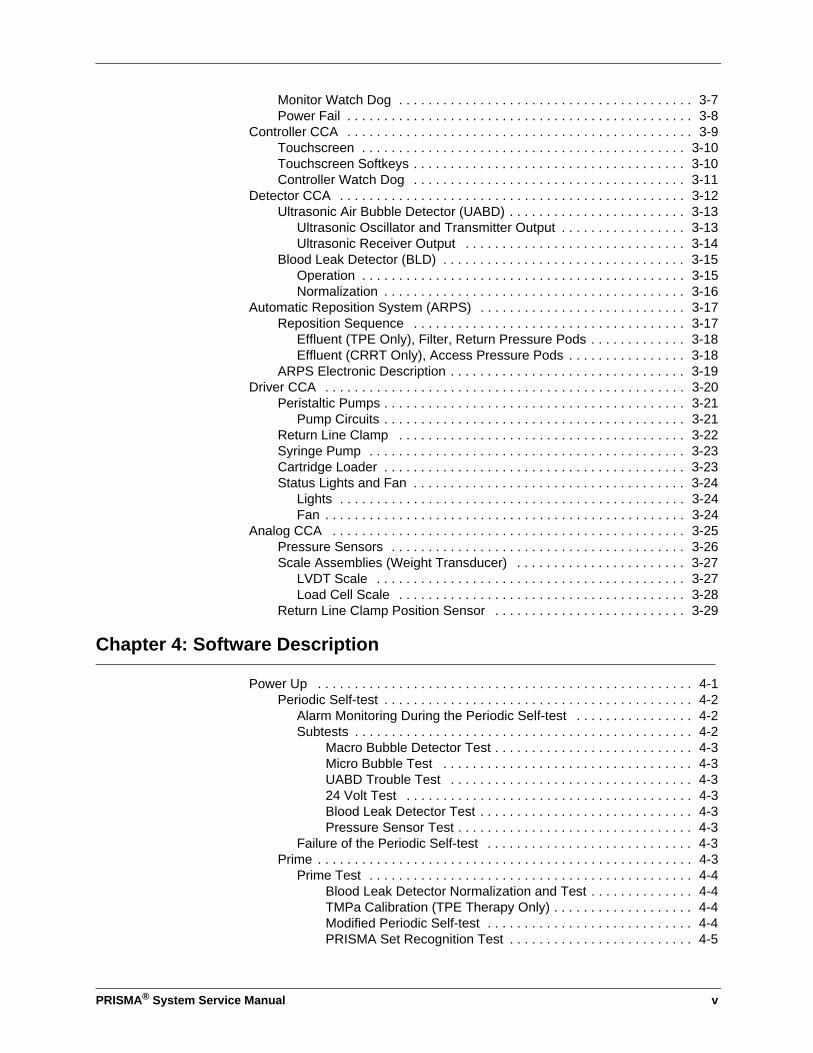
Monitor Watch Dog . . . . . . . . . . . . . . . . . . . . . . . . . . . . . . . . . . . . . . . . 3-7Power Fail . . . . . . . . . . . . . . . . . . . . . . . . . . . . . . . . . . . . . . . . . . . . . . . 3-8
Controller CCA . . . . . . . . . . . . . . . . . . . . . . . . . . . . . . . . . . . . . . . . . . . . . . . 3-9Touchscreen . . . . . . . . . . . . . . . . . . . . . . . . . . . . . . . . . . . . . . . . . . . . 3-10Touchscreen Softkeys . . . . . . . . . . . . . . . . . . . . . . . . . . . . . . . . . . . . . 3-10Controller Watch Dog . . . . . . . . . . . . . . . . . . . . . . . . . . . . . . . . . . . . . 3-11
Detector CCA . . . . . . . . . . . . . . . . . . . . . . . . . . . . . . . . . . . . . . . . . . . . . . . 3-12Ultrasonic Air Bubble Detector (UABD) . . . . . . . . . . . . . . . . . . . . . . . . 3-13
Ultrasonic Oscillator and Transmitter Output . . . . . . . . . . . . . . . . . 3-13Ultrasonic Receiver Output . . . . . . . . . . . . . . . . . . . . . . . . . . . . . . 3-14
Blood Leak Detector (BLD) . . . . . . . . . . . . . . . . . . . . . . . . . . . . . . . . . 3-15Operation . . . . . . . . . . . . . . . . . . . . . . . . . . . . . . . . . . . . . . . . . . . . 3-15Normalization . . . . . . . . . . . . . . . . . . . . . . . . . . . . . . . . . . . . . . . . . 3-16
Automatic Reposition System (ARPS) . . . . . . . . . . . . . . . . . . . . . . . . . . . . 3-17Reposition Sequence . . . . . . . . . . . . . . . . . . . . . . . . . . . . . . . . . . . . . 3-17
Effluent (TPE Only), Filter, Return Pressure Pods . . . . . . . . . . . . . 3-18Effluent (CRRT Only), Access Pressure Pods . . . . . . . . . . . . . . . . 3-18
ARPS Electronic Description . . . . . . . . . . . . . . . . . . . . . . . . . . . . . . . . 3-19Driver CCA . . . . . . . . . . . . . . . . . . . . . . . . . . . . . . . . . . . . . . . . . . . . . . . . . 3-20
Peristaltic Pumps . . . . . . . . . . . . . . . . . . . . . . . . . . . . . . . . . . . . . . . . . 3-21Pump Circuits . . . . . . . . . . . . . . . . . . . . . . . . . . . . . . . . . . . . . . . . . 3-21
Return Line Clamp . . . . . . . . . . . . . . . . . . . . . . . . . . . . . . . . . . . . . . . 3-22Syringe Pump . . . . . . . . . . . . . . . . . . . . . . . . . . . . . . . . . . . . . . . . . . . 3-23Cartridge Loader . . . . . . . . . . . . . . . . . . . . . . . . . . . . . . . . . . . . . . . . . 3-23Status Lights and Fan . . . . . . . . . . . . . . . . . . . . . . . . . . . . . . . . . . . . . 3-24
Lights . . . . . . . . . . . . . . . . . . . . . . . . . . . . . . . . . . . . . . . . . . . . . . . 3-24Fan . . . . . . . . . . . . . . . . . . . . . . . . . . . . . . . . . . . . . . . . . . . . . . . . . 3-24
Analog CCA . . . . . . . . . . . . . . . . . . . . . . . . . . . . . . . . . . . . . . . . . . . . . . . . 3-25Pressure Sensors . . . . . . . . . . . . . . . . . . . . . . . . . . . . . . . . . . . . . . . . 3-26Scale Assemblies (Weight Transducer) . . . . . . . . . . . . . . . . . . . . . . . 3-27
LVDT Scale . . . . . . . . . . . . . . . . . . . . . . . . . . . . . . . . . . . . . . . . . . 3-27Load Cell Scale . . . . . . . . . . . . . . . . . . . . . . . . . . . . . . . . . . . . . . . 3-28
Return Line Clamp Position Sensor . . . . . . . . . . . . . . . . . . . . . . . . . . 3-29
Chapter 4: Software Description
Power Up . . . . . . . . . . . . . . . . . . . . . . . . . . . . . . . . . . . . . . . . . . . . . . . . . . . 4-1Periodic Self-test . . . . . . . . . . . . . . . . . . . . . . . . . . . . . . . . . . . . . . . . . . 4-2
Alarm Monitoring During the Periodic Self-test . . . . . . . . . . . . . . . . 4-2Subtests . . . . . . . . . . . . . . . . . . . . . . . . . . . . . . . . . . . . . . . . . . . . . . 4-2
Macro Bubble Detector Test . . . . . . . . . . . . . . . . . . . . . . . . . . . 4-3Micro Bubble Test . . . . . . . . . . . . . . . . . . . . . . . . . . . . . . . . . . 4-3UABD Trouble Test . . . . . . . . . . . . . . . . . . . . . . . . . . . . . . . . . 4-324 Volt Test . . . . . . . . . . . . . . . . . . . . . . . . . . . . . . . . . . . . . . . 4-3Blood Leak Detector Test . . . . . . . . . . . . . . . . . . . . . . . . . . . . . 4-3Pressure Sensor Test . . . . . . . . . . . . . . . . . . . . . . . . . . . . . . . . 4-3
Failure of the Periodic Self-test . . . . . . . . . . . . . . . . . . . . . . . . . . . . 4-3Prime . . . . . . . . . . . . . . . . . . . . . . . . . . . . . . . . . . . . . . . . . . . . . . . . . . . 4-3
Prime Test . . . . . . . . . . . . . . . . . . . . . . . . . . . . . . . . . . . . . . . . . . . . 4-4Blood Leak Detector Normalization and Test . . . . . . . . . . . . . . 4-4TMPa Calibration (TPE Therapy Only) . . . . . . . . . . . . . . . . . . . 4-4Modified Periodic Self-test . . . . . . . . . . . . . . . . . . . . . . . . . . . . 4-4PRISMA Set Recognition Test . . . . . . . . . . . . . . . . . . . . . . . . . 4-5
vi PRISMA® System Service Manual
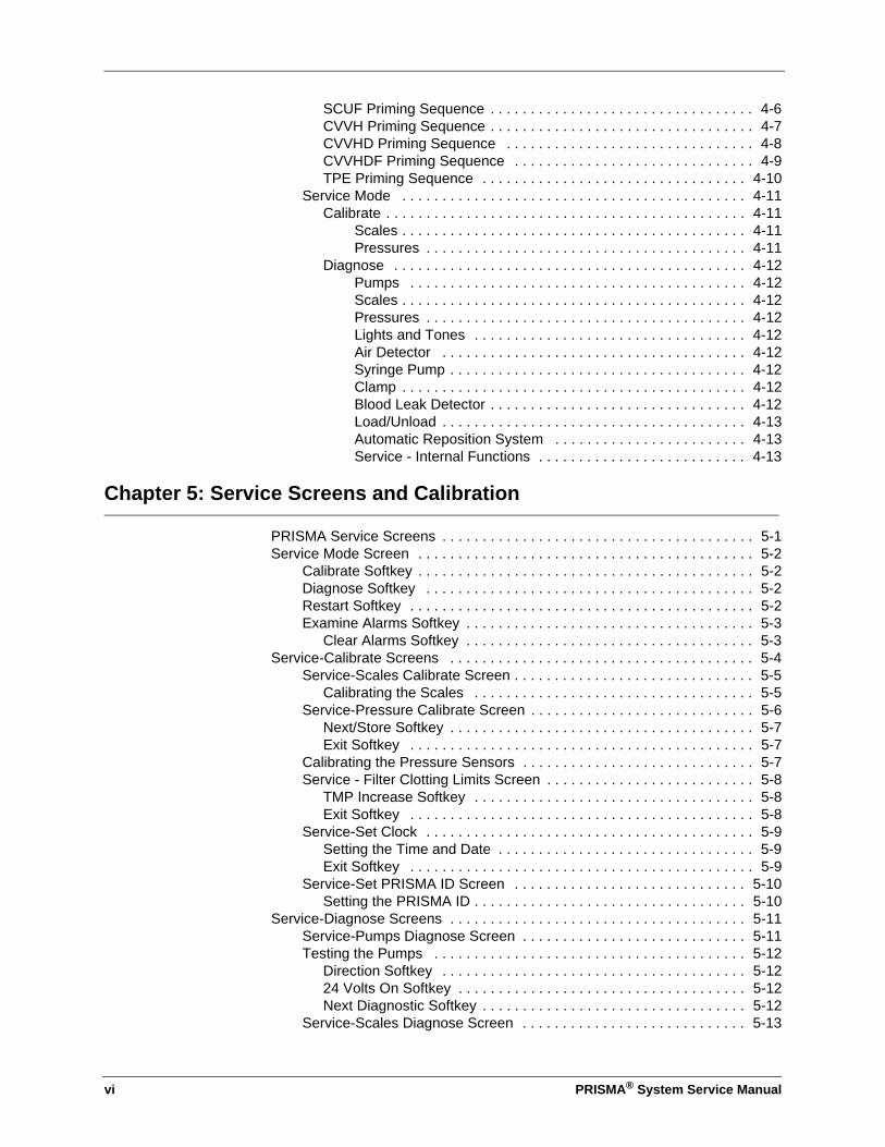
SCUF Priming Sequence . . . . . . . . . . . . . . . . . . . . . . . . . . . . . . . . . 4-6CVVH Priming Sequence . . . . . . . . . . . . . . . . . . . . . . . . . . . . . . . . . 4-7CVVHD Priming Sequence . . . . . . . . . . . . . . . . . . . . . . . . . . . . . . . 4-8CVVHDF Priming Sequence . . . . . . . . . . . . . . . . . . . . . . . . . . . . . . 4-9TPE Priming Sequence . . . . . . . . . . . . . . . . . . . . . . . . . . . . . . . . . 4-10
Service Mode . . . . . . . . . . . . . . . . . . . . . . . . . . . . . . . . . . . . . . . . . . . 4-11Calibrate . . . . . . . . . . . . . . . . . . . . . . . . . . . . . . . . . . . . . . . . . . . . . 4-11
Scales . . . . . . . . . . . . . . . . . . . . . . . . . . . . . . . . . . . . . . . . . . . 4-11Pressures . . . . . . . . . . . . . . . . . . . . . . . . . . . . . . . . . . . . . . . . 4-11
Diagnose . . . . . . . . . . . . . . . . . . . . . . . . . . . . . . . . . . . . . . . . . . . . 4-12Pumps . . . . . . . . . . . . . . . . . . . . . . . . . . . . . . . . . . . . . . . . . . 4-12Scales . . . . . . . . . . . . . . . . . . . . . . . . . . . . . . . . . . . . . . . . . . . 4-12Pressures . . . . . . . . . . . . . . . . . . . . . . . . . . . . . . . . . . . . . . . . 4-12Lights and Tones . . . . . . . . . . . . . . . . . . . . . . . . . . . . . . . . . . 4-12Air Detector . . . . . . . . . . . . . . . . . . . . . . . . . . . . . . . . . . . . . . 4-12Syringe Pump . . . . . . . . . . . . . . . . . . . . . . . . . . . . . . . . . . . . . 4-12Clamp . . . . . . . . . . . . . . . . . . . . . . . . . . . . . . . . . . . . . . . . . . . 4-12Blood Leak Detector . . . . . . . . . . . . . . . . . . . . . . . . . . . . . . . . 4-12Load/Unload . . . . . . . . . . . . . . . . . . . . . . . . . . . . . . . . . . . . . . 4-13Automatic Reposition System . . . . . . . . . . . . . . . . . . . . . . . . 4-13Service - Internal Functions . . . . . . . . . . . . . . . . . . . . . . . . . . 4-13
Chapter 5: Service Screens and Calibration
PRISMA Service Screens . . . . . . . . . . . . . . . . . . . . . . . . . . . . . . . . . . . . . . . 5-1Service Mode Screen . . . . . . . . . . . . . . . . . . . . . . . . . . . . . . . . . . . . . . . . . . 5-2
Calibrate Softkey . . . . . . . . . . . . . . . . . . . . . . . . . . . . . . . . . . . . . . . . . . 5-2Diagnose Softkey . . . . . . . . . . . . . . . . . . . . . . . . . . . . . . . . . . . . . . . . . 5-2Restart Softkey . . . . . . . . . . . . . . . . . . . . . . . . . . . . . . . . . . . . . . . . . . . 5-2Examine Alarms Softkey . . . . . . . . . . . . . . . . . . . . . . . . . . . . . . . . . . . . 5-3
Clear Alarms Softkey . . . . . . . . . . . . . . . . . . . . . . . . . . . . . . . . . . . . 5-3Service-Calibrate Screens . . . . . . . . . . . . . . . . . . . . . . . . . . . . . . . . . . . . . . 5-4
Service-Scales Calibrate Screen . . . . . . . . . . . . . . . . . . . . . . . . . . . . . . 5-5Calibrating the Scales . . . . . . . . . . . . . . . . . . . . . . . . . . . . . . . . . . . 5-5
Service-Pressure Calibrate Screen . . . . . . . . . . . . . . . . . . . . . . . . . . . . 5-6Next/Store Softkey . . . . . . . . . . . . . . . . . . . . . . . . . . . . . . . . . . . . . . 5-7Exit Softkey . . . . . . . . . . . . . . . . . . . . . . . . . . . . . . . . . . . . . . . . . . . 5-7
Calibrating the Pressure Sensors . . . . . . . . . . . . . . . . . . . . . . . . . . . . . 5-7Service - Filter Clotting Limits Screen . . . . . . . . . . . . . . . . . . . . . . . . . . 5-8
TMP Increase Softkey . . . . . . . . . . . . . . . . . . . . . . . . . . . . . . . . . . . 5-8Exit Softkey . . . . . . . . . . . . . . . . . . . . . . . . . . . . . . . . . . . . . . . . . . . 5-8
Service-Set Clock . . . . . . . . . . . . . . . . . . . . . . . . . . . . . . . . . . . . . . . . . 5-9Setting the Time and Date . . . . . . . . . . . . . . . . . . . . . . . . . . . . . . . . 5-9Exit Softkey . . . . . . . . . . . . . . . . . . . . . . . . . . . . . . . . . . . . . . . . . . . 5-9
Service-Set PRISMA ID Screen . . . . . . . . . . . . . . . . . . . . . . . . . . . . . 5-10Setting the PRISMA ID . . . . . . . . . . . . . . . . . . . . . . . . . . . . . . . . . . 5-10
Service-Diagnose Screens . . . . . . . . . . . . . . . . . . . . . . . . . . . . . . . . . . . . . 5-11Service-Pumps Diagnose Screen . . . . . . . . . . . . . . . . . . . . . . . . . . . . 5-11Testing the Pumps . . . . . . . . . . . . . . . . . . . . . . . . . . . . . . . . . . . . . . . 5-12
Direction Softkey . . . . . . . . . . . . . . . . . . . . . . . . . . . . . . . . . . . . . . 5-1224 Volts On Softkey . . . . . . . . . . . . . . . . . . . . . . . . . . . . . . . . . . . . 5-12Next Diagnostic Softkey . . . . . . . . . . . . . . . . . . . . . . . . . . . . . . . . . 5-12
Service-Scales Diagnose Screen . . . . . . . . . . . . . . . . . . . . . . . . . . . . 5-13
PRISMA® System Service Manual vii
Next Diagnostic Softkey . . . . . . . . . . . . . . . . . . . . . . . . . . . . . . . . . 5-13Service-Pressure Diagnose Screen . . . . . . . . . . . . . . . . . . . . . . . . . . 5-14
Enable Reposition Transducer Softkey . . . . . . . . . . . . . . . . . . . . . 5-14Next Diagnostic Softkey . . . . . . . . . . . . . . . . . . . . . . . . . . . . . . . . . 5-14
Service-Lights and Tones Diagnose Screen . . . . . . . . . . . . . . . . . . . . 5-15Next Diagnostic Softkey . . . . . . . . . . . . . . . . . . . . . . . . . . . . . . . . . 5-15
Service-Air Detector Diagnose Screen . . . . . . . . . . . . . . . . . . . . . . . . 5-16Macro Test Softkey . . . . . . . . . . . . . . . . . . . . . . . . . . . . . . . . . . . . 5-16Micro Test Softkey . . . . . . . . . . . . . . . . . . . . . . . . . . . . . . . . . . . . . 5-16Next Diagnostic . . . . . . . . . . . . . . . . . . . . . . . . . . . . . . . . . . . . . . . 5-16
Service-Syringe Pump Diagnose Screen . . . . . . . . . . . . . . . . . . . . . . 5-17Continuous Softkey . . . . . . . . . . . . . . . . . . . . . . . . . . . . . . . . . . . . 5-17Stop Softkey . . . . . . . . . . . . . . . . . . . . . . . . . . . . . . . . . . . . . . . . . . 5-17Bolus Softkey . . . . . . . . . . . . . . . . . . . . . . . . . . . . . . . . . . . . . . . . . 5-17Adjust Rate Softkey . . . . . . . . . . . . . . . . . . . . . . . . . . . . . . . . . . . . 5-17Next Diagnostic Softkey . . . . . . . . . . . . . . . . . . . . . . . . . . . . . . . . . 5-17
Service-Clamp Diagnose Screen . . . . . . . . . . . . . . . . . . . . . . . . . . . . 5-18Clamp Command Softkey . . . . . . . . . . . . . . . . . . . . . . . . . . . . . . . 5-18Monitor Power and Control Power Softkeys . . . . . . . . . . . . . . . . . 5-18Next Diagnostic Softkey . . . . . . . . . . . . . . . . . . . . . . . . . . . . . . . . . 5-18
Service-Blood Leak Detector Diagnose Screen . . . . . . . . . . . . . . . . . 5-19Test Softkey . . . . . . . . . . . . . . . . . . . . . . . . . . . . . . . . . . . . . . . . . . 5-19Normalize Softkey . . . . . . . . . . . . . . . . . . . . . . . . . . . . . . . . . . . . . 5-19Next Diagnostic Softkey . . . . . . . . . . . . . . . . . . . . . . . . . . . . . . . . . 5-19Signal 1 and Signal 2 . . . . . . . . . . . . . . . . . . . . . . . . . . . . . . . . . . . 5-20Difference and Average . . . . . . . . . . . . . . . . . . . . . . . . . . . . . . . . . 5-20
Service-Pod Reposition Diagnose Screen . . . . . . . . . . . . . . . . . . . . . 5-21Effluent, Access, Filter, and Return Valve Softkeys . . . . . . . . . . . . 5-21Motor Softkey . . . . . . . . . . . . . . . . . . . . . . . . . . . . . . . . . . . . . . . . . 5-21Direction Softkey . . . . . . . . . . . . . . . . . . . . . . . . . . . . . . . . . . . . . . 5-21Pressure and Reposition Press Display . . . . . . . . . . . . . . . . . . . . . 5-22Next Diagnostic Softkey . . . . . . . . . . . . . . . . . . . . . . . . . . . . . . . . . 5-22
Service-Internal Diagnose Screen . . . . . . . . . . . . . . . . . . . . . . . . . . . . 5-23Test Monitor and Test Control Watch Dog Softkeys . . . . . . . . . . . 5-23Test Video Softkey . . . . . . . . . . . . . . . . . . . . . . . . . . . . . . . . . . . . . 5-23Set PM Timer Status Softkey . . . . . . . . . . . . . . . . . . . . . . . . . . . . . 5-23Test Softkey . . . . . . . . . . . . . . . . . . . . . . . . . . . . . . . . . . . . . . . . . . 5-23
Restore Defaults Softkey . . . . . . . . . . . . . . . . . . . . . . . . . . . . . . . . . . . 5-24Exit Softkey . . . . . . . . . . . . . . . . . . . . . . . . . . . . . . . . . . . . . . . . . . 5-24
Test Mode . . . . . . . . . . . . . . . . . . . . . . . . . . . . . . . . . . . . . . . . . . . . . . . . . . 5-24
Chapter 6: Alarm System and Troubleshooting
Alarm Troubleshooting Contents . . . . . . . . . . . . . . . . . . . . . . . . . . . . . . . . . . 6-3Component and System Troubleshooting . . . . . . . . . . . . . . . . . . . . . . . 6-5
Warning Alarms . . . . . . . . . . . . . . . . . . . . . . . . . . . . . . . . . . . . . . . . . . . . . . . 6-7Control Unit Actions . . . . . . . . . . . . . . . . . . . . . . . . . . . . . . . . . . . . . . . . 6-7Operator Response . . . . . . . . . . . . . . . . . . . . . . . . . . . . . . . . . . . . . . . . 6-7Overridden Warning Alarms . . . . . . . . . . . . . . . . . . . . . . . . . . . . . . . . . 6-7
Malfunction Alarms . . . . . . . . . . . . . . . . . . . . . . . . . . . . . . . . . . . . . . . . . . . . 6-8Control Unit Actions . . . . . . . . . . . . . . . . . . . . . . . . . . . . . . . . . . . . . . . . 6-8Operator Response . . . . . . . . . . . . . . . . . . . . . . . . . . . . . . . . . . . . . . . . 6-8Overridden Malfunction Alarms . . . . . . . . . . . . . . . . . . . . . . . . . . . . . . . 6-9
viii PRISMA® System Service Manual
Caution Alarms . . . . . . . . . . . . . . . . . . . . . . . . . . . . . . . . . . . . . . . . . . . . . . . 6-9Control Unit Actions . . . . . . . . . . . . . . . . . . . . . . . . . . . . . . . . . . . . . . . . 6-9Operator Response . . . . . . . . . . . . . . . . . . . . . . . . . . . . . . . . . . . . . . . . 6-9
Advisory Alarms . . . . . . . . . . . . . . . . . . . . . . . . . . . . . . . . . . . . . . . . . . . . . 6-10Control Unit Actions . . . . . . . . . . . . . . . . . . . . . . . . . . . . . . . . . . . . . . . 6-10Operator Response . . . . . . . . . . . . . . . . . . . . . . . . . . . . . . . . . . . . . . . 6-10Overridden Advisory Alarms . . . . . . . . . . . . . . . . . . . . . . . . . . . . . . . . 6-10
Alarm Priorities . . . . . . . . . . . . . . . . . . . . . . . . . . . . . . . . . . . . . . . . . . . . . . 6-11Component and System Troubleshooting . . . . . . . . . . . . . . . . . . . . . . . . . . 6-54Self-test Troubleshooting . . . . . . . . . . . . . . . . . . . . . . . . . . . . . . . . . . . . . . 6-76
Interpreting a Self-test Failure Code . . . . . . . . . . . . . . . . . . . . . . . . . . 6-76Manual Termination of Treatment . . . . . . . . . . . . . . . . . . . . . . . . . . . . . . . . 6-87
Manual Termination With Blood Return . . . . . . . . . . . . . . . . . . . . . . . 6-87Manual Termination Without Blood Return . . . . . . . . . . . . . . . . . . . . . 6-88
Diaphragm Reposition Procedure . . . . . . . . . . . . . . . . . . . . . . . . . . . . . . . . 6-89Diaphragm Reposition Procedure for CRRT . . . . . . . . . . . . . . . . . . . . 6-89
Supplies Needed . . . . . . . . . . . . . . . . . . . . . . . . . . . . . . . . . . . . . . 6-89Access and Effluent Pods (CRRT) . . . . . . . . . . . . . . . . . . . . . . . . . 6-89Filter and Return Pods (CRRT) . . . . . . . . . . . . . . . . . . . . . . . . . . . 6-90
Diaphragm Reposition Procedure for TPE . . . . . . . . . . . . . . . . . . . . . 6-93Supplies Needed . . . . . . . . . . . . . . . . . . . . . . . . . . . . . . . . . . . . . . 6-93Access Pod (TPE) . . . . . . . . . . . . . . . . . . . . . . . . . . . . . . . . . . . . . 6-93Filter, Return, and Effluent Pods (TPE) . . . . . . . . . . . . . . . . . . . . . 6-94
Air Removal Procedures for All Therapies . . . . . . . . . . . . . . . . . . . . . . . . . 6-95Supplies Needed . . . . . . . . . . . . . . . . . . . . . . . . . . . . . . . . . . . . . . . . . 6-96Access Pressure Pod . . . . . . . . . . . . . . . . . . . . . . . . . . . . . . . . . . . . . 6-96Return Pressure Pod . . . . . . . . . . . . . . . . . . . . . . . . . . . . . . . . . . . . . . 6-96Effluent Pressure Pod . . . . . . . . . . . . . . . . . . . . . . . . . . . . . . . . . . . . . 6-96Filter Pressure Pod/Filter Header . . . . . . . . . . . . . . . . . . . . . . . . . . . . 6-96Return Line During Air in Blood Alarm . . . . . . . . . . . . . . . . . . . . . . . . 6-97
Component Operation Verification Procedures . . . . . . . . . . . . . . . . . . . . . . 6-98Syringe Pump Accuracy . . . . . . . . . . . . . . . . . . . . . . . . . . . . . . . . . . . 6-98Syringe Pump Bolus Volume and Delivery Rate . . . . . . . . . . . . . . . . . 6-98Pump Flow Rate Ranges . . . . . . . . . . . . . . . . . . . . . . . . . . . . . . . . . . 6-99Pump Flow Rate Accuracy . . . . . . . . . . . . . . . . . . . . . . . . . . . . . . . . . 6-99
Blood Pump . . . . . . . . . . . . . . . . . . . . . . . . . . . . . . . . . . . . . . . . . . 6-99Effluent Pump . . . . . . . . . . . . . . . . . . . . . . . . . . . . . . . . . . . . . . . . 6-100Dialysate Pump . . . . . . . . . . . . . . . . . . . . . . . . . . . . . . . . . . . . . . 6-101Replacement Pump . . . . . . . . . . . . . . . . . . . . . . . . . . . . . . . . . . . 6-102
Audible Alarm . . . . . . . . . . . . . . . . . . . . . . . . . . . . . . . . . . . . . . . . . . 6-103Pressure Sensor Operating Range . . . . . . . . . . . . . . . . . . . . . . . . . . 6-103Pressure Sensor Alarms . . . . . . . . . . . . . . . . . . . . . . . . . . . . . . . . . . 6-104Access Line Pressure Sensor . . . . . . . . . . . . . . . . . . . . . . . . . . . . . . 6-105Return Line Pressure Sensor . . . . . . . . . . . . . . . . . . . . . . . . . . . . . . 6-106Filter Pressure Sensor . . . . . . . . . . . . . . . . . . . . . . . . . . . . . . . . . . . . 6-106TMP Alarms . . . . . . . . . . . . . . . . . . . . . . . . . . . . . . . . . . . . . . . . . . . . 6-107Air Detector . . . . . . . . . . . . . . . . . . . . . . . . . . . . . . . . . . . . . . . . . . . . 6-108Blood Leak Detector . . . . . . . . . . . . . . . . . . . . . . . . . . . . . . . . . . . . . 6-109

PRISMA® System Service Manual ix
Chapter 7: Maintenance
Operator Maintenance . . . . . . . . . . . . . . . . . . . . . . . . . . . . . . . . . . . . . . . . . 7-1Routine Cleaning . . . . . . . . . . . . . . . . . . . . . . . . . . . . . . . . . . . . . . . . . . 7-1Blood Leak Detector . . . . . . . . . . . . . . . . . . . . . . . . . . . . . . . . . . . . . . . 7-1
Technical Preventive Maintenance . . . . . . . . . . . . . . . . . . . . . . . . . . . . . . . . 7-2Tools, Supplies, and Equipment Required . . . . . . . . . . . . . . . . . . . . . . . . . . 7-3
Visual Inspection and Cleaning . . . . . . . . . . . . . . . . . . . . . . . . . . . . . . . 7-4Component Replacement . . . . . . . . . . . . . . . . . . . . . . . . . . . . . . . . . . . 7-4
Pressure Pod Sealing Cones (total 4 of cones) . . . . . . . . . . . . . . . . 7-4Automatic Reposition System Filter and Pump Segment . . . . . . . . 7-5Pump Rotor Washers (total of 8 washers) . . . . . . . . . . . . . . . . . . . . 7-5
Power Supply Check on Power Supply Interface CCA . . . . . . . . . . . . . 7-7Service Mode Checkout . . . . . . . . . . . . . . . . . . . . . . . . . . . . . . . . . . . . 7-7
Service-Pumps Diagnose Screen . . . . . . . . . . . . . . . . . . . . . . . . . . 7-8Service-Scales Diagnose Screen . . . . . . . . . . . . . . . . . . . . . . . . . . . 7-9Service Pressure Diagnose Screen . . . . . . . . . . . . . . . . . . . . . . . . . 7-9
Reposition Transducer . . . . . . . . . . . . . . . . . . . . . . . . . . . . . . 7-10Service-Lights and Tones Diagnose Screen . . . . . . . . . . . . . . . . . 7-10Service-Air Detector Screen . . . . . . . . . . . . . . . . . . . . . . . . . . . . . . 7-10Service-Syringe Pump Diagnose Screen . . . . . . . . . . . . . . . . . . . . 7-11Service-Clamp Diagnose Screen . . . . . . . . . . . . . . . . . . . . . . . . . . 7-11Service-Blood Leak Detector Diagnose Screen . . . . . . . . . . . . . . . 7-12Load/Unload Functions . . . . . . . . . . . . . . . . . . . . . . . . . . . . . . . . . 7-12Service-Pod Reposition Diagnose Screen . . . . . . . . . . . . . . . . . . . 7-12
Effluent Valve . . . . . . . . . . . . . . . . . . . . . . . . . . . . . . . . . . . . . 7-12Access Valve . . . . . . . . . . . . . . . . . . . . . . . . . . . . . . . . . . . . . 7-13Filter Valve . . . . . . . . . . . . . . . . . . . . . . . . . . . . . . . . . . . . . . . 7-13Return Valve . . . . . . . . . . . . . . . . . . . . . . . . . . . . . . . . . . . . . . 7-13
Service-Internal Screen . . . . . . . . . . . . . . . . . . . . . . . . . . . . . . . . . 7-14Functional Checkout . . . . . . . . . . . . . . . . . . . . . . . . . . . . . . . . . . . . . . 7-14
Setup and Prime . . . . . . . . . . . . . . . . . . . . . . . . . . . . . . . . . . . . . . 7-15Fluid Accuracy . . . . . . . . . . . . . . . . . . . . . . . . . . . . . . . . . . . . . . . . 7-15Access Pressure Alarm Verification . . . . . . . . . . . . . . . . . . . . . . . . 7-16Incorrect Weight Change Alarms . . . . . . . . . . . . . . . . . . . . . . . . . . 7-16Excess Pt. Fluid Loss or Gain Alarm . . . . . . . . . . . . . . . . . . . . . . . 7-17Fluid Accuracy During Alarm . . . . . . . . . . . . . . . . . . . . . . . . . . . . . 7-17
Electrical Safety Inspection . . . . . . . . . . . . . . . . . . . . . . . . . . . . . . . . . . . . . 7-18Electrical Safety Inspection Tests . . . . . . . . . . . . . . . . . . . . . . . . . . . . 7-18Primary Fusing . . . . . . . . . . . . . . . . . . . . . . . . . . . . . . . . . . . . . . . . . . 7-18Warning Label . . . . . . . . . . . . . . . . . . . . . . . . . . . . . . . . . . . . . . . . . . . 7-19PM Sticker . . . . . . . . . . . . . . . . . . . . . . . . . . . . . . . . . . . . . . . . . . . . . . 7-19Preventive Maintenance Timer Status . . . . . . . . . . . . . . . . . . . . . . . . 7-19Preventive Maintenance Checklist . . . . . . . . . . . . . . . . . . . . . . . . . . . 7-19
Power Supply Adjustment . . . . . . . . . . . . . . . . . . . . . . . . . . . . . . . . . . . . . . 7-20Restoring Monitor CCA BBRAMs . . . . . . . . . . . . . . . . . . . . . . . . . . . . . . . . 7-21

x PRISMA® System Service Manual
Chapter 8:Illustrated Parts
Chapter 9: Schematics
Chapter 10: Specifications
Environmental Requirements . . . . . . . . . . . . . . . . . . . . . . . . . . . . . . . . . . . . . . . . . . 10-1Physical Characteristics of PRISMA Control Unit . . . . . . . . . . . . . . . . . . . . 10-1AC Power . . . . . . . . . . . . . . . . . . . . . . . . . . . . . . . . . . . . . . . . . . . . . . . . . . . . . . . . . 10-1Electrical Safety . . . . . . . . . . . . . . . . . . . . . . . . . . . . . . . . . . . . . . . . . . . . . . . . . . . . . 10-2Anticoagulant Settings . . . . . . . . . . . . . . . . . . . . . . . . . . . . . . . . . . . . . . . . . . . . . . . . 10-3Flow Rate Ranges and Accuracy . . . . . . . . . . . . . . . . . . . . . . . . . . . . . . . . . . . . . . . 10-3Flow Rate Ranges and Accuracy (cont.) . . . . . . . . . . . . . . . . . . . . . . . . . . . . . . . . . . 10-4TPE Settings . . . . . . . . . . . . . . . . . . . . . . . . . . . . . . . . . . . . . . . . . . . . . . . . . . . . . . . 10-4TPE Settings (cont.) . . . . . . . . . . . . . . . . . . . . . . . . . . . . . . . . . . . . . . . . . . . . . . . . . 10-5Displayed Values Accuracy . . . . . . . . . . . . . . . . . . . . . . . . . . . . . . . . . . . . . 10-5Displayed Values Accuracy (cont.) . . . . . . . . . . . . . . . . . . . . . . . . . . . . . . . 10-6(difference between Actual Patient Plasma Loss and displayed value) . . . 10-6Audible Alarm . . . . . . . . . . . . . . . . . . . . . . . . . . . . . . . . . . . . . . . . . . . . . . . . . . . . . . 10-6Access Line Pressure Sensor . . . . . . . . . . . . . . . . . . . . . . . . . . . . . . . . . . . . . . . . . . 10-6Access Line Pressure Sensor (cont.) . . . . . . . . . . . . . . . . . . . . . . . . . . . . . . . . . . . . 10-7Return Line Pressure Sensor . . . . . . . . . . . . . . . . . . . . . . . . . . . . . . . . . . . . . . . . . . 10-7Filter Pressure Sensor . . . . . . . . . . . . . . . . . . . . . . . . . . . . . . . . . . . . . . . . . . . . . . . . 10-7Filter Pressure . . . . . . . . . . . . . . . . . . . . . . . . . . . . . . . . . . . . . . . . . . . . . . . . . . . . . . 10-8Effluent Line Pressure Sensor . . . . . . . . . . . . . . . . . . . . . . . . . . . . . . . . . . . . . . . . . . 10-9Air Bubble Detector . . . . . . . . . . . . . . . . . . . . . . . . . . . . . . . . . . . . . . . . . . . . . . . . . . 10-9Blood Leak Detector . . . . . . . . . . . . . . . . . . . . . . . . . . . . . . . . . . . . . . . . . . . . . . . . 10-10
Appendix A
Note on the combined use of Prisma and the ECG monitoring system . . . . A-1
Appendix B: Fluid Balance Description (CRRT)
Flow Rates . . . . . . . . . . . . . . . . . . . . . . . . . . . . . . . . . . . . . . . . . . . . B-1How PRISMA Monitors the Flow Rates . . . . . . . . . . . . . . . . . . . . . . B-1
Dialysate, Replacement, and Effluent Fluids . . . . . . . . . . . . . . B-1How PRISMA Determines “Actual Patient Fluid Removed” . . . . . . . B-1Protecting the Patient from Fluid Imbalance . . . . . . . . . . . . . . . . . . B-2“Incorrect Weight Change” Alarm . . . . . . . . . . . . . . . . . . . . . . . . . . . B-2
Excess Pt. Fluid Removed or gained . . . . . . . . . . . . . . . . . . . . B-3Common Causes of Incorrect Weight Change . . . . . . . . . . . . . B-3Remedying the Incorrect Weight Change Alarm . . . . . . . . . . . B-3
"Excess Pt. Fluid Loss or Gain Limit" . . . . . . . . . . . . . . . . . . . . . . . . B-3"Excess Pt. Fluid Loss or Gain" Alarm . . . . . . . . . . . . . . . . . . . . . . . B-4Warnings . . . . . . . . . . . . . . . . . . . . . . . . . . . . . . . . . . . . . . . . . . . . . B-4Precautions . . . . . . . . . . . . . . . . . . . . . . . . . . . . . . . . . . . . . . . . . . . B-5
Displayed Values Accuracy . . . . . . . . . . . . . . . . . . . . . . . . . . . . . . . . . . . . . . B-5
PRISMA® System Service Manual xi
Appendix C: Fluid Balance Description (TPE)
Flow Rates . . . . . . . . . . . . . . . . . . . . . . . . . . . . . . . . . . . . . . . . . . . . C-1How PRISMA Monitors the Flow Rates . . . . . . . . . . . . . . . . . . . . . . C-1
Replacement, and Effluent Fluids . . . . . . . . . . . . . . . . . . . . . . C-1How PRISMA Determines “Actual Patient Plasma Loss” . . . . . . . . . C-1Protecting the Patient from Fluid Imbalance . . . . . . . . . . . . . . . . . . C-2“Incorrect Weight Change” Alarm . . . . . . . . . . . . . . . . . . . . . . . . . . . C-2
Excess Pt. Fluid Removed or gained . . . . . . . . . . . . . . . . . . . . C-3Common Causes of Incorrect Weight Change . . . . . . . . . . . . . C-3Remedying the Incorrect Weight Change Alarm . . . . . . . . . . . C-3
"Excess Pt. Fluid Loss or Gain Limit" . . . . . . . . . . . . . . . . . . . . . . . . C-3"Excess Pt. Fluid Loss or Gain" Alarm . . . . . . . . . . . . . . . . . . . . . . . C-4Warnings . . . . . . . . . . . . . . . . . . . . . . . . . . . . . . . . . . . . . . . . . . . . . C-4Precautions . . . . . . . . . . . . . . . . . . . . . . . . . . . . . . . . . . . . . . . . . . . C-5
Displayed Values Accuracy . . . . . . . . . . . . . . . . . . . . . . . . . . . . . . . . . . . . . . C-5
Index

xii PRISMA® System Service Manual
This page is left intentionally blank

Preface
PRISMA® System Service Manual xiii
Preface
Indications
The PRISMA System is indicated for continuous solute and/or fluid removal in patients with acute renal failure or fluid overload and for therapeutic plasma exchange in patients with diseases where removal of plasma components is indicated. All treatments administered via the PRISMA System must be prescribed by a physician.
Contraindications
There are no known contraindications to continuous renal replacement therapy or therapeutic plasma exchange except those associated with the infusion of replacement fluids.
System Components
The PRISMA System consists of the PRISMA Control Unit and a disposable PRISMA Set. (PRISMA Sets are purchased separately.)
Control Unit
Each PRISMA Control Unit is packaged with the following items:
• Column (hollow pole with flat plate attached to one end)
• Base with casters
• Installation kit
• Calibration weights (2)
• PRISMA System Operator’s Manual
Set
Use only PRISMA Sets (manufactured by GAMBRO or HOSPAL) with the PRISMA Control Unit. Check with your sales representative for availability.
Two types of disposable sets may be used for CRRT (Continuous Renal Replacement therapies), which include SCUF, CVVH, CVVHD, CVVHDF.
Preface
xiv PRISMA® System Service Manual
• Post-dilution set (provides for addition of replacement solution after blood leaves the filter).
• Pre-dilution set (provides for addition of replacement solution before blood enters the filter).
A third type of disposable set, the PRISMA TPE Set, must be used for the TPE therapy.
PRISMA Sets come with an effluent bag. To facilitate priming, a prime collection bag is preconnected to each set. Additional PRISMA Effluent Bags can be purchased separately.
Where to Find Information About the PRISMA System
Operator’s Manual
The PRISMA Operator’s Manual provides installation, operating, maintenance, and troubleshooting instructions, as well as general information. Specific information about system overview, operation, and pressure monitoring for CRRT can be found in Chapter 3 and for TPE in Chapter 4. See the Contents section for a complete list of topics.
On-line Instructions
Detailed operating instructions are incorporated in the software of the PRISMA Control Unit. The instructions are available on-line, through the interactive display. Instructions include the following screens:
• Operating screens (step-by-step instructions the operator follows each time in setting up, administering, and ending patient treatments).
• Alarm screens (instructions if an alarm situation occurs).
• Help screens (additional information about an Operating or Alarm screen).
PRISMA Set Instructions for Use
Instructions for use are provided with PRISMA Sets.
Warnings
1. Carefully read the PRISMA System Operator’s Manual and the PRISMA Set Instructions for Use before operating this device. Before first use, ensure that the installation test has been successfully performed. See the Installation chapter of the PRISMA System Operator’s Manual for instructions on performing the installation test.
2. Operate this device only in accordance with the procedures contained in the PRISMA System Operator’s Manual, the PRISMA Set Instructions for Use,

Preface
PRISMA® System Service Manual xv
and the on-line instructions. The use of operating or maintenance procedures other than those published by the manufacturer, or the use of accessory devices not recommended by the manufacturer, can result in patient injury or death.
3. The manufacturer will not be responsible for patient safety if the procedures to operate, maintain, and calibrate the PRISMA System are other than those specified in the PRISMA System Operator’s Manual, this PRISMA System Service Manual, the PRISMA Set Instructions for Use, and the on-line instructions. Anyone who performs the procedures must be appropriately trained and qualified.
4. Ensure that the proper PRISMA Set has been chosen for the selected therapy. Using the wrong set for the therapy can cause patient injury or death.
5. All electrical installations must comply with all applicable local electrical codes and the manufacturer’s specifications.
6. The PRISMA Control Unit weighs approximately 23 kg (50 lb). Use at least two people to lift it out of the shipping carton. Handle the control unit carefully.
7. Use only PRISMA Sets manufactured by GAMBRO or HOSPAL with the PRISMA Control Unit. The use of non-PRISMA sets can result in patient injury or death.
8. Do not connect a patient to the PRISMA System during the installation test. Be sure that the test is conducted using a container of water to substitute for the patient.
9. If a Malfunction alarm occurs during the installation test, the PRISMA Control Unit has failed the test. Do not use the control unit. Call a trained and qualified technician for service.
10. Use only prescribed dialysate solution and replacement solution/fluid with the PRISMA System. Use only dialysate solution and replacement solution/fluid which conform with applicable national registration, standards, or laws and the Council Directive 65/65/EEC. If a commercially avaliable replacement solution is used, it must be labeled as intended for intravenous injection.
11. Only replacement solutions in bags of maximum 5 liters may be placed on the replacement scale.
12. Ensure that dialysate solution and replacement solution/fluid are of appropriate composition and at appropriate temperature, as prescribed by a physician. Before using a solution/fluid, make sure it is free of precipitates and other particulate matter. The use of incorrect solution/fluid can result in patient injury or death.
13. To assure proper anticoagulant flow control, use only 20-cc BD, Braun, Monoject, or Terumo luer lock syringes. The internal diameter of these syringes has been verified at the time of printing this manual. The manufacturer of the PRISMA System cannot be held liable for subsequent changes that may occur to syringe dimensions. See Anticoagulant Settings in the Specifications chapter for verified internal diameters.

Preface
xvi PRISMA® System Service Manual
14. Use only luer lock syringes with the PRISMA System. Use of non-luer lock syringes can result in patient blood loss if the anticoagulant line becomes dislodged from the syringe. See #12 (above) for the list of approved syringes.
15. Do not hang anything except fluid bags/containers from the scale hooks on the bottom of the PRISMA Control Unit. Foreign objects on the scale hooks can significantly alter fluid balance, resulting in patient injury or death.
16. Do not support the fluid bags/containers by any means other than the provided scale hooks. Fluid balance can be significantly altered, resulting in patient injury or death. When hanging a fluid bag, always center it on the 3-hook assembly, so that its weight is evenly distributed.
17. Lock brakes on casters to limit movement of the control unit that might pull on tubing connected to the patient.
18. All blood and fluid flowpaths of the set are sterile and nonpyrogenic. Use aseptic technique when handling the blood and fluid lines in the set.
19. During priming and operation, observe closely for leakage at joints and connections within the set. Leakage can cause blood loss or air embolism. If leakage cannot be stopped by tightening the connections, replace the set.
20. Do not allow air to enter the blood compartment of the filter after priming has started. If a large amount of air enters, the set must be replaced.
21. Do not connect a blood heater to the return line below the air bubble detector. The PRISMA System cannot detect air introduced in the line below the air detector.
22. If a patient is not connected to the PRISMA Set for CRRT (pre- or post-dilution) shortly after priming is complete, flush the set with at least 500 ml priming solution (saline with heparin added) before connecting a patient. This requires use of a new bag of priming solution and a new (empty) collection bag.
23. If a patient is not connected to the PRISMA TPE Set shortly after priming is complete, flush the set with at least 250 ml priming solution (saline with heparin added) before connecting a patient. This requires the use of a new bag of priming solution.
24. Ensure proper functioning of the display and software by confirming the correct sequence of the numbers on the Prime Test Passed screen. If the numbers displayed are not in sequential order, manually unload the set and call for service—do not connect a patient.
25. All lines in the PRISMA Set have a preattached slide clamp. Clamp the following lines after priming is complete and before starting a patient treatment (Run mode). For SCUF and CVVHD, clamp the replacement line; for SCUF and CVVH, clamp the dialysate line; for TPE, clamp the clear segment of the access line; for all therapies, clamp the anticoagulant line (if not in use).
26. Connect the PRISMA Set to a patient via venous blood access and return devices. A dual-lumen venous catheter is the recommended blood access device; however, two single-lumen venous catheters can also be used.
Preface
PRISMA® System Service Manual xvii
27. During a patient treatment, ensure the display is operating correctly by checking the following functions:
a. Numbers on the Set TPE Prescription, Set Flow Rates, and Modify Anticoag screens should scroll in correct increments and in sequential order when the arrow keys are pressed. (If the increment or sequence is incorrect, terminate the treatment and call for service. See the Specifications chapter for a list of the correct increments.)
b. A short beeping sound should be generated each time a softkey is pressed. (If a beep is not generated, terminate the treatment and call for service.)
28. Due to the nature of use of the PRISMA Set (low blood flow rate, extended treatment time, and other special factors), the possibility for coagulation within the blood flowpath is substantially enhanced. Give careful attention to the possible medical hazards associated with coagulation of the blood flowpath.
29. Closely monitor the patient’s clotting parameters, especially when increasing the amount of anticoagulant delivered or after changing the anticoagulant syringe.
30. Weigh the patient daily, or as appropriate, to assure proper fluid balance. Monitor the patient’s blood chemistry as often as necessary.
31. Collecting blood samples from improper sample sites in the set can lead to incorrect blood chemistry results.
32. When responding to any alarm, carefully follow the instructions on the displayed Alarm screen and its associated Help screen.
33. The blood leak detector must be re-normalized if the effluent line is repositioned or removed and then reinserted into the blood leak detector after treatment (Run mode) has started. This is done by pressing the NORMALIZE BLD softkey on the More Softkeys screen. The detector must be re-normalized before continuing a patient treatment.
34. To clear some alarms, the PRISMA Control Unit must override the alarm for 60 seconds. The Alarm screen on the display notifies the operator that the alarm will be overridden if the OVERRIDE softkey is pressed. A new alarm for the same condition cannot occur during the override period; therefore, carefully observe the set and all operation during the override period. If the alarm condition is still present after the override period, the control unit issues a new alarm.
35. The control unit may not be able to detect disconnections of the set from the patient’s catheter (in all therapies), from the red segment of the access line (for TPE), or from the clear segment of the access line (for TPE). Carefully observe the set and all operation while using the PRISMA System for a patient treatment.
36. The PRISMA Set must be changed after 72 hours of use. Continued use beyond 72 hours could result in rupture of the pump segments, with patient injury or death.

Preface
xviii PRISMA® System Service Manual
Note: To assure adequate filter performance, it is recommended that the PRISMA Set be changed after 24 hours of use. An Advisory alarm occurs if the set is not changed after 72 hours. The operator can reset this advisory to occur between 24 and 72 hours of operation.
37. Always inspect the blood flowpath for signs of clotting before returning the blood in the set to the patient (via the automatic Return Blood option, or the Manual Termination With Blood Return procedure). If clotting is suspected, do not return the blood to the patient.
38. If power is lost to the PRISMA Control Unit, the patient can be manually disconnected from the set. If performing a Manual Termination With Blood Return, visually check for air in the blood return line until the patient is disconnected.
39. If the display goes blank while power is on, immediately terminate the treatment and call for service.
40. During TPE therapy, in order to avoid hemolysis the pressure gradient between arterial inlet and filtrate outlet should be strictly controlled and the blood flow rate should not fall below 100 ml/min. Carefully observe the set for signs of hemolysis.
41. To minimize the risk of hemolysis in TPE therapy, the PRISMA System monitors the TMPa and issues alarms if maximum pressure limits are reached. When performing TPE, additional monitoring for hemolysis is also recommended.
42. It is advisable to obtain a detailed drug history before each TPE procedure. For drugs potentially affected by TPE, the physician should either adjust the doses or give the medications immediately after the procedure.
43. Renal replacement therapy with high-permeability hemofilters may reduce the concentration of therapeutic drugs in the patient. The prescribing physician should consult the literature of the drug manufacturer for further information and consider the need to monitor the concentration of the drug in order to assure an appropriate therapeutic dosage.
44. Use only the PRISMA RS232 Cable Kit for communicating with external equipment. All external equipment must be IEC 60950 compliant.
45. Use only GAMBRO or HOSPAL approved accessories.
46. Electrically isolated peristaltic pumps such as those on the PRISMA System can produce electrostatic charges in the disposable set. While these electrostatic charges are not hazardous to the patient, they may cause an artifact on cardiac monitors (such as ECG) or pacemaking devices. If a cardiac dysrhythmia is exhibited, press the STOP softkey on the PRISMA System and reassess the cardiac rhythm before treating the patient. To significantly reduce the likelihood of producing artifacts, follow the instructions given in Appendix A of this manual.
47. To reduce the risk of contact between the pump rotors and the patients and operators, it is recommended to wear properly fastened coats and gather up hair in suitably sized caps. Also be careful with ties, bracelets, necklaces and anything else that may get caught up in PRISMA.
Preface
PRISMA® System Service Manual xix
48. Ignoring and/or indiscriminately pressing the CONTINUE softkey as a response to alarms of "INCORRECT WEIGHT CHANGE DETECTED" may lead to incorrect patient weight loss or gain, and may result in serious patient injury or death.
Always identify and solve the originating cause of an "Incorrect Weight Change Detected" alarm before pressing the CONTINUE softkey.
49. If you receive additional "Incorrect Weight Change Detected" alarms and the cause cannot be identified, you should first solve the problem, and then consider discontinuing and restarting the treatment, if possible.
50. The Displayed Actual Patient Fluid Removed/Patient Plasma Loss will be less than the one calculated from the "operator-set" Patient Fluid Removal/Patient Plasma Loss and the Elapsed time shown in the Status screen (this applies also in the History screen) if:
(a) treatment is voluntarily stopped and then later resumed; or (b) an alarm occurs that stops the replacement, dialysate and effluent pumps. "Operator-set" Patient fluid removed shall be calculated multiplying Run Time in History screen by Patient fluid removal rate.Additional Stop/Restarts ( event ) for bag changes when not completely full/empty may add 1ml more for each event.
Precautions
1. Procedures using the PRISMA System must be performed under the responsibility of a physician.
2. There are no operator-serviceable parts inside this device. Repairs must be performed by a trained and qualified technician.
3. Store the PRISMA Set in a dry place, between 0 °C (32 °F) and 30 °C (86 °F).
4. Prior to using the PRISMA Control Unit, let the unit rest at ambient operating temperature for 1 hour.
5. The rear handle of the PRISMA Control Unit is intended only for pushing the unit on its casters; the handle is not intended for lifting the unit.
6. The accuracy of the PRISMA Control Unit depends on accurate scale and pressure calibration. Ensure that scales and pressure sensors are accurately calibrated. Calibrations must be performed by a trained and qualified person. Calibration instructions are provided in this PRISMA System Service Manual.
7. Some solvents and chemicals, if used in contact with the filter, could damage the PRISMA Set. No chemical of this type should be used without permission of the manufacturer. The following are especially forbidden: (a) halogenated aromatic and aliphatic solvents; (b) ketonic solvents.
8. To prevent contamination, the PRISMA Set must be used as soon as its package and sterilization caps are removed.

Preface
xx PRISMA® System Service Manual
9. Do not use the PRISMA Set if the package is damaged, if the sterilization caps are missing or loose, or if the blood lines are kinked.
10. Destroy the PRISMA Set after a single use, using appropriate procedures for potentially contaminated material. Do not resterilize.
11. When handling PRISMA Sets, hospital personnel should take adequate precautions at all times to prevent exposure to or transmission of HIV, hepatitis virus, or other infectious agents.
12. The PRISMA System is not designed for a heater to be connected to the replacement solution line. A heater generates air bubbles which collect in the return line pressure pod. Therefore, it is recommended not to use a heater on the replacement solution line.
13. If a heater is connected to the dialysate line, the PRISMA System does not automatically prime the additional tubing needed for the heater. Separate priming of this tubing is required.
14. Do not use any type of lubricant on the internal or external components of the PRISMA Control Unit or PRISMA Set. Use of lubricant can adversely affect performance of the control unit.
15. If anticoagulation of the blood flowpath is not desired, fill a 20-cc BD, Braun, Monoject, or Terumo luer lock syringe with priming solution and load it into the syringe pump during Setup mode, while the Prepare Solutions screen is on the display. This assures the anticoagulant line will be primed during the automatic priming cycle.
16. After priming is complete, do not remove the pressure pods from the pressure sensor housings. Pressure sensing becomes inaccurate if pods are removed, or if they are removed and then reinserted in the sensor housings. If pods are removed, the set must be changed or the Diaphragm Reposition procedure must be performed.
17. Press only one softkey at a time. Pressing two or more softkeys simultaneously causes the PRISMA Control Unit to ignore all except the first keypress.
18. Change fluid bags/containers when the appropriate Caution alarm occurs (Replacement Bag Empty, Dialysate Bag Empty, Effluent Bag Full, Replacement Container Empty). Changing a bag before the alarm occurs may only be done by using the Change Bags function and following the instructions on the Change Bags screen. When changing bags/containers during TPE therapy, it is important to enter the new replacement container volume on the Change Bags screen. If the volume for the replacement container is wrong, air could be introduced into the set.
19. For priming in the TPE therapy, the plasma filter specification requires four priming cycles. Instructions are provided via the on-line screens.
20. During the initialization test, when the PRISMA Control Unit is first turned on, Service mode can be accessed by pressing certain softkeys simultaneously. Only trained and qualified technicians should access Service mode. If Service mode is inadvertently entered, turn the unit off, then on to return to Operating mode.

Preface
PRISMA® System Service Manual xxi
21. Use a 20-gauge (or smaller diameter) needle to obtain blood or fluid samples, to remove trapped air from the PRISMA Set, or to reposition pod diaphragms. Use of larger needles can cause holes in the sample sites, resulting in blood loss or air embolism. Use aseptic technique whenever inserting needles into sample sites.
22. When repositioning pod diaphragms, injecting or removing more than1 cc of fluid may move the diaphragm beyond the center point of the pod. See “Diaphragm Reposition Procedure” in Chapter 6: Alarm System and Troubleshooting for more information.
23. When operating the PRISMA System, avoid bumping the cartridge of the PRISMA Set. Bumping may cause the pump segments to become dislodged in the raceways of the pumps and result in loss of pump effectiveness. If this happens, a variety of alarms will occur to alert you. These include the Caution: Effluent Weight, Caution: Replacement Weight, Caution: Dialysate Weight, Advisory: Return Pressure, and Advisory: Access Pressure alarms.
24. Hemofiltration (CVVH) with high replacement solution flow rates can result in transmembrane pressures (TMP) which may be sufficiently high to cause one of the following alarms: Warning: Filter is Clotted; Caution: TMP Excessive; Advisory: Filter is Clotting; Advisory: TMP Too High. If these alarms occur, reduce the replacement solution flow rate until the alarm no longer appears. Use of predilution sets with the largest surface area filter available will minimize occurrence of these alarms.
25. If the room temperature changes by more than ± 3° C (5.4 °F), STOP the treatment and call service to recalibrate the scales. Do not continue to use the PRISMA Control Unit until the scales are recalibrated.
26. As treatment proceeds, carefully monitor patient fluid balance levels and all the I/O Data on the Status and History screens. Fluid balance monitoring should include frequent totaling of patient fluid input/output and periodic verification of the patient's weight using an independent (non-PRISMA) means.

Preface
xxii PRISMA® System Service Manual
Symbols and CertificationIf applicable, the following symbols appear on or near the serial number label or other permanently affixed labels of this device. See the Specifications chapter for more information.
1. This symbol indicates that the equipment applied part is Type BF, defibrillation-proof per IEC 601.1.
2. This symbol indicates that consultation of the accompanying documents prior to equipment operation is critical to the safe operation of the device.
3. This symbol indicates that the device meets the “drip proof” classification requirements of IEC 601.1 under the applicable conditions.
4. This symbol indicates that the device requires an alternating supply current.
5. This symbol indicates that conductors carrying high voltage are nearby and that these could be hazardous if contacted.
6. This symbol is located near functional ground locations on this device.
7. This symbol is located near protective ground locations on this device.
8. This symbol identifies the point of connection of a potential equalization conductor.
9. This symbol indicates a fuse.
10. This symbol indicates that certain components within this equipment are sensitive to electrostatic discharge.
IPX1
Preface
PRISMA® System Service Manual xxiii
Disclaimer
The manufacturer (and/or subsidiaries) accepts responsibility for the safety, reliability, and performance of this equipment only if all operational procedures, calibrations, and repairs are carried out by appropriately trained and qualified people; if all equipment modifications are authorized in writing by the manufacturer and carried out by appropriately trained and qualified people; if the electrical installation of the relevant room complies with all applicable local electrical codes and, if applicable, IEC requirements; and if the equipment is used in accordance with the published instructions for use (this document).
The manufacturer (and/or subsidiaries) will provide on request, at nominal cost, a service manual which contains all necessary circuit diagrams, component parts lists, calibration instructions, and service information to enable appropriately trained and qualified technical personnel to repair those parts of this equipment which the manufacturer considers to be repairable.
11. This symbol indicates that the equipment conforms to Council Directive 93/42/EEC, of 14 June, 1993 relating to Medical Devices. Also indicates that the notified body which has approved the manufacturer’s quality system is the British Standards Institution (BSI). The CE Mark affixed to the PRISMA Control Unit covers only the PRISMA Control Unit. Disposables specified for use with the PRISMA Control Unit have separate CE Marks. See Warning number 7.
Preface
xxiv PRISMA® System Service Manual
Service Information
For technical assistance, contact your representative at the applicable address below.
AUSTRALIA GAMBRO PTY Ltd.P.O. Box 6604 BHBCBaulkham Hills3, Hudson AvenueCastle HillNEW SOUTH WALES 2154Tel. 61 - 2 9 680 27 11Fax 61 - 2 9 634 13 75
AUSTRIA HOSPAL Medizintechnische Produkte GmbHRicoweg 30 AA-2351 Wr. NEUDORFTel. 43/2.23.664.666Fax 43/2.23.664.666-55
BELGIUM HOSPAL S.A.Groenveldstraat, 11B - 3001 HEVERLEETel. 32 / 16 31 10 20Fax 32 / 16 31 10 39
BRAZIL GAMBRO do Brasil Ltda Avenida Luiz Carlos Berrini 1297Conjunto 92BR-04571 SAO PAOLOTel. 55 - 11 55 06 90 12Fax 55 - 11 55 06 47 04
CANADA HOSPAL GAMBRO Inc9157, du Champ D´eau StreetSt. LeonardCA-QUEBEC H1P 3M3Tel. 1 - 514 327 16 35Fax 1 - 514 327 08 22
FRANCE HOSPAL SA61 av. Tony GarnierF - 69007 LyonTel. 33 / (0) 4 37 28 11 11Fax 33 / (0) 4 37 28 11 44
GERMANY Gambro HOSPAL GmbHLochhamer Str. 15D - 82152 Planegg-MartinsriedTel. 49 / (0) 89. 89933-0Fax 49 / (0) 89. 89933-2999

Preface
PRISMA® System Service Manual xxv
ITALY HOSPAL SpAVia Ferrarese, 219/9I - 40 128 BolognaTel. 39 / 051 63 82 411 Fax 39 / 051 32 74 77
NETHERLANDS GAMBRO HOSPAL BVFranse Akker 1NL - 4824 AL BREDATel. +31 / (0) 76 530 3600Fax +31 / (0) 76 541 1968
MEXICO GAMBRO de MEXICO S.A. de CV Vasco de Quiroga 1900, Piso 3MX-Santa FeMEXICO D. F. 01210Tel. 52 - 52 92 31 00Fax 52 - 52 92 31 13
SPAIN HOSPAL SANápoles, 249 - 1°E - 08013 BarcelonaTel. 34 / 93 457 00 74Fax 34 / 93 457 76 72
SWITZERLAND HOSPAL GAMBRO SCHWEIZ AGSägereistrasse 24CH - 8152 GLATTBRUGGTel. 41/ 1 828 82 82 Fax 41/ 1 828 82 83
UNITED KINGDOM HOSPAL GAMBRO LtdUnit 1, Ermine Business ParkHuntingdonGB-CAMBRIDGESHIRE PE18 6YATel. 44 / 1480 444 000 Fax 44 / 1480 434 084
REST of EUROPE , AFRICA & MIDDLE EAST
HOSPAL GAMBRO EXPORTMagistratsvagen 10P.O. Box 10101S - 220 10 LundTo order Parts :Fax 46/46 169 610Middle East: Tel. 46/46 169 134Africa: Tel. 46/46 169 270Russia: Tel. 46/46 169 171East Europe: Tel. 46/45 169 171

Preface
xxvi PRISMA® System Service Manual
Disposal of Lithium Energy Cell
The PRISMA Control Unit contains a lithium energy cell. The cell is embedded in a semiconductor on the monitor circuit card assembly. When replacing this component, follow local regulations for proper disposal.
Disposal of Packaging Material
The PRISMA Control Unit shipping carton, foam packing, and other packaging material should be disposed of according to local regulations.
Warranty
Since GAMBRO DASCO has no knowledge or control of how non-GAMBRO DASCO service work is conducted or what effect such work will have on a machine’s operation and performance, GAMBRO DASCO will in no way be responsible or liable for any damages resulting from the operation or performance of any device, or any injury caused thereby, after repairs have been attempted by anyone other than a factory representative of GAMBRO DASCO.
Under no circumstances will GAMBRO DASCO be liable for indirect or consequential damages of any kind, its liability being hereby limited solely to repair or replacement.
This warranty is in lieu of any other expressed or implied warranties, including any implied warranty of salability or fitness for use and of any other obligation on the part of GAMBRO DASCO.

Chapter 1: Introduction
Chapter 1: Introduction
This service manual is for service technicians who will maintain and repair the PRISMA® Control Unit. It is important that the service technician thoroughly read and understand the contents of this manual before attempting to repair or maintain the machine. Only trained and qualified service technicians should perform the procedures described in this manual.
Introduction
The PRISMA System provides continuous fluid management, renal replacement therapies, and therapeutic plasma exchange (as an option). The system is intended for patients who have acute renal failure and/or fluid overload, or patients with diseases where removal of plasma components is indicated.
Blood Access
All PRISMA therapies use venous blood access and return. A dual-lumen venous catheter is the recommended blood access device; however, two single-lumen venous catheters can also be used.
PRISMA Control Unit Functions
The PRISMA Control Unit performs the following functions:
• Loads and primes the PRISMA Set automatically.
• Pumps blood through the blood flowpath of the set.
• Delivers anticoagulant solution into the blood flowpath.
• Controls fluid removal/plasma loss from the patient.
• Pumps sterile replacement solution/fluid and/or sterile dialysate. Pumps effluent.
• Monitors the system and alerts the operator to abnormal situations through alarms.
Therapy Overview
The PRISMA Control Unit pumps venous blood from the patient, through the filter in a disposable PRISMA Set, and back to the patient’s venous circulation. As the blood passes through the filter, fluid removal/plasma loss and/or solute clearance can take place.
PRISMA® System Service Manual 1-1

Chapter 1: Introduction
PRISMA Therapy Options
The PRISMA System provides continuous fluid management, four different continuous renal replacement therapies (CRRT), as well as therapeutic plasma exchange (TPE) therapy. During the Setup procedure, the operator selects the therapy desired.
• SCUF (Slow Continuous Ultrafiltration)
Provides patient fluid removal by ultrafiltration.
• CVVH (Continuous Veno-venous Hemofiltration)
Provides solute removal by convection. Can provide patient fluid removal, if desired.
• CVVHD (Continuous Veno-venous Hemodialysis)
Provides solute clearance by diffusion. Can provide patient fluid removal, if desired.
• CVVHDF (Continuous Veno-venous Hemodiafiltration)
Provides solute removal by both convection and diffusion. Can provide patient fluid removal, if desired.
• TPE (Therapeutic Plasma Exchange; optional)
Provides plasma exchange by membrane filtration.
Mechanisms of Therapy
The mechanisms of ultrafiltration, hemofiltration, hemodialysis, and therapeutic plasma exchange are used in providing the PRISMA therapy options.
Ultrafiltration
In ultrafiltration, plasma water with solutes is pulled from the patient’s blood across the semipermeable membrane in the filter. The effluent pump automatically controls the ultrafiltration rate.
Hemofiltration
In hemofiltration, plasma water with solutes is pulled from the patient’s blood across the semipermeable membrane by means of ultrafiltration. A replacement solution is simultaneously infused into the blood flowpath.
The replacement solution adds back some or all of the water removed, as well as the wanted solutes. Unwanted solutes are not replaced, thus their concentration decreases in the patient’s blood. Solute removal is achieved by convection (solvent drag across the membrane).
Hemodialysis
In hemodialysis, unwanted solutes pass from the patient’s blood across the semipermeable membrane and into dialysate flowing at counter flow through the fluid compartment of the filter.
1-2 PRISMA® System Service Manual
Chapter 1: Introduction
The concentration of unwanted solutes is lower in the dialysate than in the blood, causing the solutes to diffuse from an area of greater concentration (the patient’s blood) to an area of lesser concentration (the dialysate solution). Solute clearance is achieved by diffusion.
Hemodiafiltration
In hemodiafiltration, both hemodialysis and hemofiltration are used. Solute removal occurs by convection and diffusion.
Dialysate solution is pumped through the fluid compartment of the filter. At the same time, the effluent pump controls ultrafiltration and a replacement solution is infused into the blood flowpath.
Therapeutic Plasma Exchange
In therapeutic plasma exchange, plasma containing disease mediators is pulled from the patient’s blood across the filter membrane. A replacement fluid is used to replace the amount of plasma removed.
PRISMA® System Service Manual 1-3

Chapter 1: Introduction
PRISMA Control Unit
Figure 1-1 shows the PRISMA Control Unit. Following is a description of the components on the panels.
Figure 1-1. PRISMA Control Unit
Front Panel
Status Lights
Illuminate to give general indication of operating conditions.
• Green: Indicates all monitored parameters are normal during administration of the treatment (Run mode).
Display
Blood Pump
Replacement Solution/Fluid Pump
Cartridge Carrier
Pressure Sensor Housing(access line)
Air Bubble Detector
Return Line Clamp
Replacement Solution/Fluid Scale (purple) and Hook Assembly
Pressure Sensor Housing(return line)
Dialysate Pump
Pressure Sensor Housing(filter)
Tubing Guides(9 total)Right Corner Hook
Effluent Pump
Syringe Pump Assembly
Dialysate Scale(green) and Hook Assembly
Pressure Sensor Housing (effluent line)
Blood Leak Detector
Left Corner Hook
Pump Raceway (tubing path-way in each peristaltic pump)
Rotor (in each peristaltic pump)
Effluent Scale (yellow) and Hook Assembly
Status Lights
1-4 PRISMA® System Service Manual

Chapter 1: Introduction
• Yellow: Indicates a Caution or Advisory alarm has occurred, or an alarm has been overridden. Immediate patient safety is not compromised, but the operator should investigate.
Note: Yellow light also illuminates when the control unit is in Setup, Standby, End, and Custom modes. In these cases, it indicates that all monitored parameters are normal, but a patient treatment is not in progress.
• Red: Indicates a Warning or Malfunction alarm has occurred because of a condition of possible patient hazard. Immediate operator intervention is required.
Display
Shows text and softkeys. Provides operating, alarm, and help instructions. A touchscreen overlay provides “active” areas for softkeys. Pressing the softkeys allows the operator to change settings and navigate between screens.
Pressure Sensor Housings
Housings that hold the four pressure pods of the PRISMA Set. A pressure sensor (transducer) is located behind each housing. The sensors and pressure pods enable noninvasive pressure monitoring of the access line, filter, return line, and effluent line. There are no air-blood interfaces.
Peristaltic Pumps
The PRISMA System has four occlusive, peristaltic pumps. The speed of each pump is controlled by the PRISMA software. The blood pump speed is based solely on the operator-set blood flow rate. The dialysate, replacement and effluent pump speeds are based on all operator-set flow rates, as well as on the changing weights of the fluid bags in use. In this way, the desired flow rates are constantly maintained.
The pump rotors are the center component of each pump that rotates during pump operation. Each rotor has two rollers that occlude the tubing in the pump raceway. The rotating, occlusive action of the rollers moves discrete amounts of fluid through the set while preventing backflow of fluid. The pump raceway holds the pump segments of the PRISMA Set and provides a smooth and stable surface for the Set.
• The effluent pump forces ultrafiltrate and/or dialysate from the fluid compartment of the filter into the effluent bag. The effluent pump automatically controls the ultrafiltration rate based on the operator-set patient fluid removal rate and replacement solution rate (if applicable).
• The dialysate pump moves fresh dialysate solution to the fluid compartment of the filter.
• The blood pump moves blood through the PRISMA Set.
• The replacement solution pump delivers replacement solution into the blood flowpath. PRISMA Sets for CRRT are available in two replacement delivery styles: pre-dilution (before blood enters the filter) or post-dilution (after blood leaves the filter). The PRISMA TPE Set provides only post-dilution replacement delivery. This pump is an occlusive, peristaltic pump.
PRISMA® System Service Manual 1-5
Chapter 1: Introduction
Cartridge Carrier
Accepts the cartridge of the PRISMA Set; enables automatic loading of the set.
Blood Pump
Pumps blood through the blood flowpath of the set. This pump is an occlusive, peristaltic pump.
Air Bubble Detector
Continuously monitors the return line for air bubbles. A Warning alarm occurs if a macro bubble is detected, or if the number of micro bubbles exceeds the warning limit.
Pump Raceway
Tubing pathway within each peristaltic pump. The raceways accept the pump segments of the PRISMA Set.
Dialysate Pump
Pumps fresh dialysate solution into the fluid compartment of the filter. This pump is an occlusive, peristaltic pump.
Return Line Clamp
Occlusive clamp that closes during all Warning and Malfunction alarms, when power is off, and during some self-tests. Prevents blood and/or air from passing to the patient.
Tubing Guides
Hold the lines of the PRISMA Set in correct position on the control unit.
Corner Hooks
Right hook holds the priming solution bag during priming. Left hook holds the prime collection bag during priming and holds the sterile saline bag during blood return.
Blood Leak Detector
Continuously monitors the effluent line for the presence of red blood cells, indicating a leak in the filter membrane. A Warning alarm occurs if red blood cells are detected.
Note: The blood leak detector does not detect the presence of hemolyzed blood; however, a pink or red tinge in the effluent bag may indicate hemolysis. For more information, see the “Additional Troubleshooting” table in Chapter 6.
Syringe Pump Assembly
Holds the anticoagulant syringe and controls the rate of anticoagulant delivery into the blood flowpath. Anticoagulant can be delivered continuously or in boluses.
1-6 PRISMA® System Service Manual
Chapter 1: Introduction
Rotor
Center component of each peristaltic pump that rotates during pump operation. Holds two rollers that occlude the pump segment in the raceway. Occlusion moves the fluid in the pump segment forward in discrete amounts and prevents backflow.
Effluent Pump
For CRRT therapies: Pumps ultrafiltrate/dialysate; automatically controls the ultrafiltration rate, based on the operator-set patient fluid removal rate and replacement solution rate (if applicable).
For TPE therapy: Pumps remove plasma; automatically controls the plasmafiltration rate based on the operator-set patient plasma loss and replacement fluid rates. (The pump is an occlusive peristaltic pump.)
Bottom Panel
Scales
Independently monitor fluid bag/container weights. Weight information is used by PRISMA software to precisely control ultrafiltration/plasmafiltration and patient fluid removal/plasma loss. A Caution alarm sounds when the dialysate and replacement solution bags/fluid containers are nearly empty, or when the effluent bag is nearly full. The scales are color-coded: dialysate is green; replacement is purple; effluent is yellow.
Scale Hook Assemblies
Three hooks on each scale that hold needed fluid bags/containers. Bags/containers up to 5 liter volume can be used.
Right Side Panel
Power Switch
Turns power on and off to the machine. The label “I” means ON and the label “O” means OFF.
Left Side Panel
Fan
Provides continuous ventilation for the interior components of the control unit.
Rear Panel
A serial communication port (P1) and an hour meter are located on the rear panel. Access to the interior of the control unit is gained through the rear panel.
PRISMA® System Service Manual 1-7

Chapter 1: Introduction
Inside the control unit are circuit card assemblies (CCAs) and other electronic and mechanical components. Only trained and qualified service technicians should repair the interior components.
To open the rear panel, loosen the two screws located along the right-rear side of the PRISMA System. For complete descriptions of the electronic components shown in the figure below, see “Chapter 3: Electronics Description”.
Figure 1-2. PRISMA Rear Panel View
Controller CCA
The Controller CCA receives input signals from the display/touchscreen, the scales, and the Monitor CCA. The Controller CCA also sends signals to the audible and visual alarm systems and to the Driver CCA to control the pump motors and the return line clamp.
Monitor CCA
The Monitor CCA receives signals from nearly all CCAs in the PRISMA System to maintain and monitor the various systems.
Detector CCA
Signals from the air bubble and blood leak detection systems are sent to the Detector CCA.
Hour Meter and Serial Communication Port
Controller CCA
Monitor CCA
Detector CCA
Power Supply
Power Distribution CCA Fuses Power Entry Module
Automatic Reposition System (ARPS)
Analog CCA
Driver CCA(behind this panel)
Fan
1-8 PRISMA® System Service Manual

Chapter 1: Introduction
Hour Meter
Located on the outside of the rear panel, the electronic hour meter displays the time that the machine’s power has been on.
Power Supply
DC power for the PRISMA System is generated in the universal input power supply. The power supply accepts standard line voltages of 110, 220, and 240 Vac at 50/60 Hz without special wiring or hardware configurations.
Serial Communication Port
The serial communication port is located on the outside of the rear panel. This port is an RS232 link between the PRISMA System and IEC 60950 compliant equipment (data processing equipment).
Power Distribution CCA
The Power Distribution CCA is the central point for power cables that distribute power to PRISMA CCAs.
Fuses
Standard AGC fuses provide electrical protection for the PRISMA System in the event of excessive current drain.
Power Entry Module
The power entry module connects the electrical power cord to the PRISMA System power supply.
Automatic Reposition System (ARPS)
The automatic reposition system is used to ensure proper pressure monitoring by maintaining the pressure pod diaphragms of the PRISMA Set in a ‘neutral’ position.
Driver CCA
The Driver CCA contains circuitry to decode signals and power the pump motors, the return line clamp solenoid, and the alarm lamp drivers.
Analog CCA
Analog signals from the scales and the pressure monitors are received by the Analog CCA. The CCA converts the analog signals to digital signals and sends the digital information to the various CCAs in the PRISMA System.
PRISMA® System Service Manual 1-9
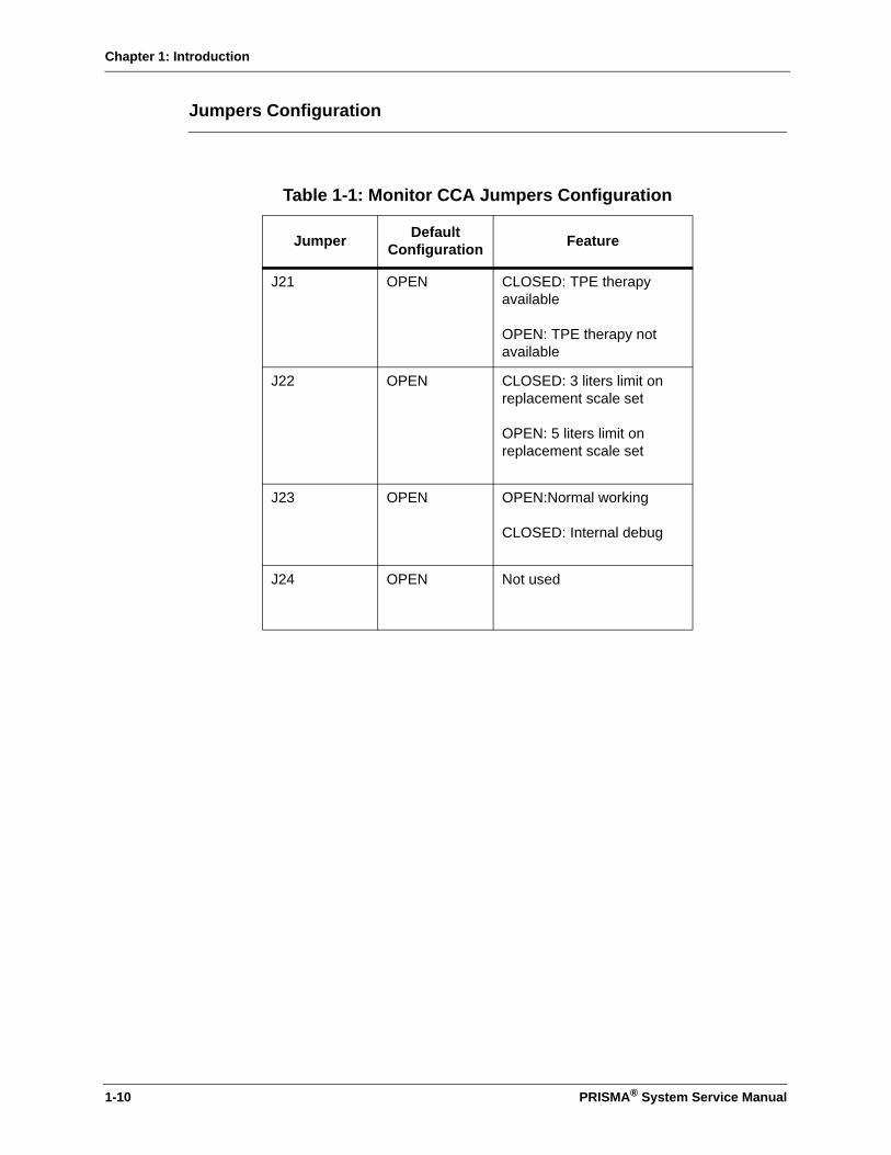
Chapter 1: Introduction
Jumpers Configuration
Table 1-1: Monitor CCA Jumpers Configuration
Jumper DefaultConfiguration Feature
J21 OPEN CLOSED: TPE therapy available
OPEN: TPE therapy not available
J22 OPEN CLOSED: 3 liters limit on replacement scale set
OPEN: 5 liters limit on replacement scale set
J23 OPEN OPEN:Normal working
CLOSED: Internal debug
J24 OPEN Not used
1-10 PRISMA® System Service Manual

Chapter 2: Continuous Renal Replacement and Therapeutic Plasma Exchange Therapies
PRISMA® System Service Manual 2-1
Chapter 2: Continuous Renal Replacement and Therapeutic Plasma Exchange Therapies
This chapter describes both continuous renal replacement therapy (CRRT) and therapeutic plasma exchange (TPE) therapy. This chapter begins with CRRT descriptions. TPE descriptions are provided beginning on page 2-31.
Figure 2-1 shows the assembled PRISMA Control Unit with a PRISMA Set for CRRT, anticoagulant syringe, and fluid bags in place. The figure portrays CVVHDF therapy, which uses both dialysate and replacement solution. (See the foldout sheet at the back of the operator’s manual for an illustration of the other CRRT therapies.) Following is a description of the components of the set and the fluid bags.
Sample Sites Ports with a plug that allow needle entry to the access, effluent, and return lines. Used to obtain fluid or blood samples or to remove trapped air. Access is gained via a 20-gauge (or smaller diameter) needle, attached to a syringe. The sample sites are color coded as follows: red on access line, yellow on effluent line, blue on return line.
Pressure Pods There are four circular “pods” in the set. Each contains a diaphragm and fits into a pressure sensor housing on the control unit. The pods and pressure sensors (inside) enable noninvasive pressure monitoring of the access line, return line, effluent line, and the filter.
Cartridge Flat, plastic component in the center of the set that holds the filter and pump segments. Has slots that accept the tabs of the cartridge carrier on the control unit. Allows automatic loading of the set.
Filter Filter containing hollow fibers made of a semipermeable membrane. Blood flows through the hollow fibers; filtrate and/or dialysate are contained in the fluid compartment.
Pump Segments
Tubing that threads into the raceway of each peristaltic pump. Loaded automatically when the cartridge carrier pulls the cartridge flush with the control unit.
Return Line(blue-striped)
Conveys blood from the filter to the patient’s blood return site.

Chapter 2: Continuous Renal Replacement and Therapeutic Plasma Exchange Therapies
2-2 PRISMA® System Service Manual
Access Line(red-striped)
Conveys blood from the patient’s blood access site to the filter.
Replacement Solution Bag
Holds prescribed replacement solution. Used in CVVH and CVVHDF.
Replacement Line (purple-striped)
Conveys replacement solution from the replacement bag to the blood flowpath. In the post-dilution set, connects to the return line, just beyond the filter blood outlet. In the pre-dilution set, connects to the access line just before the filter blood inlet.
Effluent Bag Collects ultrafiltrate and/or spent dialysate. One effluent bag is supplied with each set. Used in all therapies.
Dialysate Bag Holds prescribed dialysate solution. Used in CVVHD and CVVHDF.
Dialysate Line (green-striped)
Conveys fresh dialysate solution to the fluid side of the filter (CRRT therapies only).
Effluent Line (yellow-striped)
Conveys ultrafiltrate and/or spent dialysate from the fluid compartment of the filter to the effluent bag.
Anticoagulant Line
Conveys anticoagulant solution from the anticoagulant syringe to the blood flowpath.
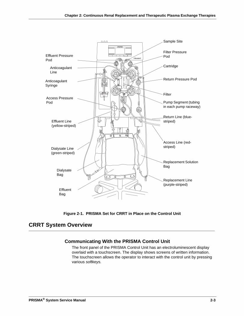
Chapter 2: Continuous Renal Replacement and Therapeutic Plasma Exchange Therapies
PRISMA® System Service Manual 2-3
Figure 2-1. PRISMA Set for CRRT in Place on the Control Unit
CRRT System Overview
Communicating With the PRISMA Control UnitThe front panel of the PRISMA Control Unit has an electroluminescent display overlaid with a touchscreen. The display shows screens of written information. The touchscreen allows the operator to interact with the control unit by pressing various softkeys.
Effluent Line(yellow-striped)
Anticoagulant Syringe
Dialysate Line (green-striped)
Anticoagulant Line
Sample Site
Replacement Line(purple-striped)
Pump Segment (tubing in each pump raceway)
Filter
Access Line (red-striped)
Return Line (blue-striped)
Return Pressure Pod
Dialysate Bag
Replacement Solution Bag
Effluent Bag
Filter Pressure Pod
Access Pressure Pod
Effluent Pressure Pod
Cartridge

Chapter 2: Continuous Renal Replacement and Therapeutic Plasma Exchange Therapies
2-4 PRISMA® System Service Manual
Interactive Display
During operation, different screens appear on the display, showing information about the treatment, giving steps the operator should take, and alerting the operator to any abnormal conditions. Specific display contents depend on the software mode and operating conditions at the moment. Some types of operating data, such as treatment history data, are only displayed when requested by the operator. The display is also a vehicle for servicing the system.
Softkeys are located along the sides and bottom of each screen. These allow the operator to give commands to the control unit and navigate between screens. The operator presses the desired softkey to initiate the function described by the softkey name.
The name and function of many of the softkeys change, depending on operating conditions. In this way, the operator is led through operating and alarm response situations.
User-controllable Settings
In order to administer the specific patient treatment prescribed by the physician, the operator controls many of the control unit’s settings. For example, pump flow rates, the Patient Fluid Removal rate, and anticoagulant settings. (Other settings are controlled only by the manufacturer or by trained and qualified service technicians.)
Table 2-8 in this chapter lists all user-controllable settings, their default values, setting options, and the mode in which they can be changed.
Default Values
There are default values for each setting. These are initially set by the manufacturer. The following information pertains to default values:
• The default value controls operation, unless the operator sets a new value during setup or administration of a treatment.
• All settings revert to their default values whenever a New Patient procedure is chosen.
• If desired, the operator can change the default values for the PRISMA therapies. This can only be done in Custom mode. For more information, see “Custom Mode” in this chapter.

Chapter 2: Continuous Renal Replacement and Therapeutic Plasma Exchange Therapies
PRISMA® System Service Manual 2-5
Current Values
Current values are those that control operation during a patient treatment.
When the operator chooses a particular therapy during the Setup procedure, the control unit uses the default values assigned to that therapy. If desired, the operator can reset some of these values during the Setup procedure (Setup mode) or while the patient treatment is underway (Run mode). Any changes made in Setup or Run modes apply only to that treatment and do not affect the default values1.
Pumps
The control unit has four occlusive, peristaltic pumps. These include the blood, replacement solution, dialysate, and effluent pumps. The control unit has one syringe pump that delivers anticoagulant solution to the blood flow, if desired.
During a patient treatment (Run mode), the peristaltic pumps turn counterclockwise. During priming of the PRISMA Set (Setup mode), some of the pumps turn clockwise. If the blood pump stops for any reason during treatment, all other pumps also stop. When the blood pump resumes, the other pumps also resume after a short delay.
The PRISMA software controls the speeds of the peristaltic pumps. The blood pump speed is based solely on the operator-set blood flow rate. The dialysate, replacement, and effluent pump speeds are based on all operator-set flow rates, as well as on the changing weights of fluid bags in use. In this way, desired flow rates are constantly maintained.
Flow Rates and Anticoagulant Settings
Flow rates are the settings that control the rate of blood flow, patient fluid removal, replacement solution infusion, dialysate flow, and effluent flow during a patient treatment. All flow rates are directly user-settable except the effluent flow rate. The effluent flow rate is automatically controlled by the PRISMA software, based on all other flow rates. Below is the formula that governs the effluent pump rate.
Anticoagulant settings are those that control delivery of anticoagulant solution to the blood flow, if anticoagulation is desired. These settings are user-settable and include the Delivery Method (Continuous or Bolus), Delivery Rate (applicable only for Continuous delivery), Bolus Volume and Bolus Interval (applicable only for Bolus delivery).
1. An exception is the setting “Language.” Changing the language in Run mode also changes the default language.
Patient fluid removal rate (ml/hr)+ Replacement solution rate (ml/hr)+ Dialysate solution rate (ml/hr)= Effluent rate (ml/hr) set by PRISMA software

Chapter 2: Continuous Renal Replacement and Therapeutic Plasma Exchange Therapies
2-6 PRISMA® System Service Manual
Adjusting the Flow Rates and Anticoagulant Settings
During the Setup procedure (Setup mode), the Set Flow Rates screen is displayed. The operator is asked to review the default flow rates and anticoagulant settings, then make any changes desired for the current treatment. During the patient’s treatment (Run mode), the operator can access the Set Flow Rates screen and adjust the flow rates and anticoagulant settings as needed.
See “Operating Modes” and “User-controllable Settings” in this chapter for more information.
If desired, the operator can change the default flow rates and anticoagulant settings in Custom mode. See “Custom Mode” in this chapter.
Patient Fluid Removal Rate
The Patient Fluid Removal rate is the net amount of fluid the PRISMA System removes from the patient each hour (after accounting for any replacement solution being used). Net fluid removal occurs whenever the operator sets the Patient Fluid Removal rate to a value above zero.
Calculating the Desired Patient Fluid Removal Rate
The PRISMA Control Unit software does not measure or account for non-PRISMA sources of patient fluid intake (such as hyperalimentation, blood, or drug infusion) or fluid output (such as urine and wound drainage). It also does not account for anticoagulant solution infused via the PRISMA anticoagulant syringe pump. The operator must account for these other sources when calculating the Patient Fluid Removal rate, as well as when calculating the patient’s input/output totals.
The following formula may be useful:
The Patient Fluid Removal rate must be adjusted if the weight loss prescribed by the physician is changed or if the patient’s non-PRISMA fluid inputs or outputs change.
Adjusting the Patient Fluid Removal Rate
During the Setup procedure (Setup mode), the Set Flow Rates screen is displayed. The operator is asked to review the default Patient Fluid Removal rate, then make any changes desired for the current treatment.
During the patient’s treatment (Run mode), the operator can access the Set Flow Rates screen and adjust the Patient Fluid Removal rate as needed. See “Operating Modes” and “User-controllable Settings” in this chapter for more information.
If desired, the operator can change the default Patient Fluid Removal rate in Custom mode. See “Custom Mode” in this chapter.
Prescribed patient fluid loss (ml/hr)+ Non-PRISMA fluid inputs (ml/hr)- Non-PRISMA fluid outputs (ml/hr)= Patient fluid removal rate to be set on the PRISMA Control Unit (ml/hr)

Chapter 2: Continuous Renal Replacement and Therapeutic Plasma Exchange Therapies
PRISMA® System Service Manual 2-7
Machine Control of Patient Fluid Removal Rate
The PRISMA software automatically calculates the ultrafiltration rate needed to achieve the Patient Fluid Removal rate. Any PRISMA replacement solution additions are automatically accounted for, as shown below.
During operation, software controls the effluent pump speed to maintain the required ultrafiltration rate.
Setting the "Excess Pt. Fluid Loss or Gain" Safety Limit
A safety limit ensures that excessive fluid cannot be unintentionally removed from or infused to the patient across the semipermeable membrane of the filter. This limit protects the patient during abnormal conditions in which the effluent pump can be manually commanded to run.
To correlate the safety limit to the individual patient, during the Setup procedure, the operator is asked to enter the physician-prescribed "Excess Pt. Fluid Loss or Gain Limit." 2 The limit controls the amount of excess patient fluid loss or gain that is allowed within the last 3 hours; the limit may be set between 130 and 400 ml. If the limit is reached, an alarm occurs that disables all fluid pumps from further use and requires the operator to end the treatment. For more information, see "Operating Modes" and "User-controllable Settings" in this chapter, and Appendix B: Fluid Balance Description (CRRT).
Fluid Balance
Actual Patient Fluid Removed
Actual Patient Fluid Removed is the net amount of fluid removed from the patient by the PRISMA System during a specified time period. It is the patient’s “PRISMA System output” for use in periodic totalling of patient I/O (input and output) volumes.
Measuring Actual Patient Fluid Removed
The three precision scales mounted on the bottom of the PRISMA Control Unit support the dialysate, replacement solution, and effluent bags and constantly measure the weight of the bags. The change in combined weight of the fluid bags in use indicates how much fluid has been removed from the patient by the control unit. When fluid bags are replaced, the software automatically accounts for the new bag weights.
2. The "Excess Pt. Fluid Loss or Gain Limit" must be prescribed by the physician. The value prescribed should be based upon the patient's ability to tolerate potential fluid imbalance.
Patient fluid removal rate (ml//hr)+ Replacement solution rate, if any (ml/hr)= Required ultrafiltration rate (ml/hr)
Chapter 2: Continuous Renal Replacement and Therapeutic Plasma Exchange Therapies
2-8 PRISMA® System Service Manual
The following formula applies:
The total Actual Patient Fluid Removed should equate with the operator-set Patient Fluid Removal rate.3
For example, if the Patient Fluid Removal rate is 100 ml/hr and 90 minutes of treatment have completed, the Actual Patient Fluid Removed will be 150 ml.
Viewing Actual Patient Fluid Removed
During a patient treatment (Run mode), the Actual Patient Fluid Removed during the current I/O Period (see description of I/O Period below) is displayed and continuously updated on the Status screen. It is also displayed on the Treatment History screen. The Treatment History screen is available for viewing during a treatment (Run mode) and when ending a treatment (End mode).
On the Treatment History screen, the operator can view the amount of Actual Patient Fluid Removed for the last full I/O Period, or for a specified period of time during the last 24 hours of treatment. See “I/O Data” and “Treatment History Data” in this chapter for more information.
I/O Data
To facilitate periodic totalling of patient I/O (input and output) volumes during a treatment, the control unit displays cumulative totals of all PRISMA-controlled fluids. This I/O Data is continually updated and displayed on the Status screen during a treatment (Run mode). Data accumulates for the length of time stipulated by the I/O Period, a user-controllable setting of 60, 30, or 15 minutes. At the end of the I/O Period, data accrual starts over at zero. If desired, the operator can set a reminder beep to signal the end of the I/O Period.
In addition to being displayed on the Status screen during a treatment, I/O Data is also accumulated and stored minute-by-minute in the treatment history memory. See “Treatment History Data” in this chapter for more information.
Depending on the therapy in use, I/O Data displayed on the Status screen includes the following:
• Time Elapsed (during the I/O Period)
• Replacement Solution Input
• Dialysate Used
• Effluent Volume (ultrafiltrate; spent dialysate)
• Actual Patient Fluid Removed
The I/O Period default is 60 minutes; the I/O Reminder Beep default is “On.” If
3. Actual Patient Fluid Removed will differ from the operator-set Patient Fluid Removal rate if: (a) treatment is stopped, then later resumed; (b) an alarm occurs that stops the replacement, dialysate, and effluent pumps.
Change in Effluent Bag weight- Change in Dial. Bag weight- Change in Repl. Bag weight= Actual patient fluid removed
Chapter 2: Continuous Renal Replacement and Therapeutic Plasma Exchange Therapies
PRISMA® System Service Manual 2-9
desired, the operator can change these default settings before beginning the Setup procedure. During a treatment (Run mode), the operator can also adjust the I/O Period and reminder beep settings. See “User-controllable Settings” in this chapter for more information.
Treatment History Data
Vital machine conditions and operating data are stored and updated minute-by-minute in software memory. The memory stores up to 24 hours of treatment data; thereafter, the old data are deleted and the new data are added minute-by-minute. The history data can be viewed on the Treatment History screen and on the Events screen. These screens are available during a treatment (Run mode) and when ending a treatment (End mode). History data for the last treatment can be viewed from the Choose Patient screen (Setup mode).
I/O History
Cumulative totals for the I/O Data displayed on the Status screen are stored and displayed on the Treatment History screen. Data for the last full I/O Period are displayed when the operator first brings the Treatment History screen to the display.
The operator can change the time period on the Treatment History screen by using the arrow softkeys. In this way, the operator can view fluid totals for all or a portion of the last 24 hours of treatment.
Events History
Certain events that may occur during setup and delivery of a treatment are stored and displayed on the Events screen.
The control unit stores the hour and minute that events occur, as well as the name of the event. Up to 100 events can be stored.
An event is recorded when any of the following occur:
• Excess Pt. Fluid Loss or Gain Limit, therapy, flow rates, and anticoagulant settings are initially selected (Setup mode).
• Prime test is passed.
• Treatment is started (Run mode).
• A flow rate or anticoagulant setting is changed during treatment.
• The sensitivity of the blood leak detector is normalized.
• An alarm occurs.
• An alarm screen is cleared from the display.
• Any of these softkeys are pressed: Load, Prime, Status (when pressed on the Change Bags screen), Change Bags, Resume, Stop, Unload.
History Data After a Treatment
After a treatment is concluded, the treatment history data is stored in memory. It

Chapter 2: Continuous Renal Replacement and Therapeutic Plasma Exchange Therapies
2-10 PRISMA® System Service Manual
can be viewed from the Choose Patient screen (Setup mode) by pressing the Last Treatment History softkey.
The Last Treatment History data is deleted when the NEW PATIENT softkey is pressed, as well as any time the date or time is changed in Custom mode.
History Data During a Power Loss
If a power loss occurs during a treatment, the treatment history data is retained in memory.
Alarm Safety System
The PRISMA Control Unit continually monitors itself and the PRISMA Set for abnormal conditions. Depending on the circumstance, the operator is alerted by the following:
• Red or yellow status light
• Audible alarm
• Alarm screen on the display, giving instructions for responding to the abnormal condition
Alarms are prioritized into Warning, Malfunction, Caution, and Advisory alarms. See Chapter 6: Alarm System and Troubleshooting for more information.
Monitoring Systems
Pressure
The PRISMA Control Unit has an integral pressure monitoring system. The system alerts the operator (via alarms) to abnormal pressure conditions, such as extreme positive pressure in the return line or clotting in the filter. See the “Pressure Monitoring” section of this chapter for more information.
Blood Leak
The PRISMA Control Unit has an infrared blood leak detector that monitors the effluent line for blood. If blood is detected, the operator is notified via a warning alarm which stops the blood pump and closes the return line clamp. See Chapter 3: Electronic Description for more information.
Air Bubble
The PRISMA Control Unit has an ultrasonic air bubble detector that continually monitors the return line for the presence of macro and micro air bubbles. If air is detected, the operator is notified via a warning alarm that stops the blood pump and closes the return line clamp. See Chapter 3: Electronic Description for more information.
CRRT Operation
Chapter 2: Continuous Renal Replacement and Therapeutic Plasma Exchange Therapies
PRISMA® System Service Manual 2-11
Startup
Startup of the PRISMA Control Unit consists of the following steps:
1. Operator turns the power switch to the “on” position.
2. The control unit performs an initialization test to check the system electronics. The Logo screen is displayed, the non-mutable buzzer sounds, and all status lights are illuminated during the test.
3. When the initialization test is successfully completed, the Choose Patient screen appears on the display and the yellow status light illuminates. This indicates the PRISMA Control Unit is in the Setup mode and is ready for operation.
Note: The above actions occur when a new PRISMA Control Unit is initially turned on. These actions also occur whenever the unit is turned on after being turned off in the Treatment Complete screen. If the control unit was last turned off in a screen other than Treatment Complete, a Query screen appears after the initialization test is completed. From the Query screen, the operator can choose one of two actions:
• Begin on the same operating screen as when the unit was turned off (by pressing the Continue key).
• Start over at the Choose Patient screen (by pressing the Restart key).
Control and Navigation
The PRISMA Control Unit is operated by means of the interactive display on the upper front panel. The screens displayed lead the operator through the operating procedures. Help screens provide additional information, if needed. The softkeys that appear on each screen enable the operator to give commands to the control unit and navigate between screens.
Screen Layout
Screens (text and softkeys) displayed by the PRISMA Control Unit have the following landmarks:
• The upper left corner shows the operating modes of the PRISMA Control Unit, with the current mode highlighted.
• The upper right corner shows the PRISMA therapies with the current therapy highlighted.
If the display goes blank while power is on, immediately terminate the treatment and service the control unit.
WARNING
!

Chapter 2: Continuous Renal Replacement and Therapeutic Plasma Exchange Therapies
2-12 PRISMA® System Service Manual
• The far right softkey of Operating and Alarm screens is labeled Help. Pressing this key provides more detail about the displayed screen.
• The far right softkey of Help screens is labeled Exit Help. Pressing this key allows the operator to return to the screen that was displayed when Help was pressed.
• An Examine Alarms key appears above the Help key whenever an alarm occurs, whenever the operator overrides an alarm, or whenever one or more lower-priority alarms are pending during an alarm. For more information, see Chapter 6: Alarm System and Troubleshooting.
• Arrows appear on certain screens. These enable the operator to adjust settings. For example, arrows are used to set the flow rates or view a certain time period within the treatment history data. By pressing and holding the arrows, the operator can scroll through the available options. By pressing and releasing the arrows, the operator can make fine adjustments.
Operating Modes
In the course of performing a treatment, the control unit passes through four normal Operating modes: Setup, Standby, Run, and End. Following is a description of each of the Operating modes.
Setup Mode
The control unit automatically goes into Setup mode after successful completion of the initialization test. Setup mode enables the operator to load the PRISMA Set for CRRT onto the control unit, prepare and connect needed solutions, and prime the set.
While the control unit is in Setup mode, appropriate alarms are enabled and the yellow status light is illuminated.
The operator follows the instructions on the display to perform the following sequential actions:
1. Enter Custom mode, if desired, to alter default settings of one or more PRISMA therapies. See “Custom Mode” in this chapter for more information.
2. View treatment history data of the last treatment.
3. Choose New Patient or Same Patient.
If New Patient is chosen, the control unit deletes the treatment history data of the last treatment and advances to the Set Excess Pt. Fluid Loss or Gain screen.If Same Patient is chosen, the control unit retains the treatment history data of the last treatment, retains the last chosen therapy and all its setting values, and advances to the Load Set screen (described in Step 6 below). The therapy can be changed among the four Continuous Renal Replacement therapies, if desired, by pressing the Cancel softkey when the Load Set screen appears.
Note: If Same Patient is chosen after completing a CRRT, the therapy cannot be
Chapter 2: Continuous Renal Replacement and Therapeutic Plasma Exchange Therapies
PRISMA® System Service Manual 2-13
changed to TPE. Changing from a CRRT to TPE can only be done through New Patient, which erases all treatment history data.
If Same Patient is chosen, dialysate and/or replacement solution bags in use can remain in use until empty. When the Same Patient treatment starts (Run mode), the cumulative count for "Excess Pt. Fluid Loss or Gain" over the last 3 hours begins again at 0 ml.
4. Review/adjust the Excess Pt. Fluid Loss or Gain Limit. (Enter the physician-prescribed value.)
5. Choose the therapy desired. The control unit accesses the default settings and screens for the therapy chosen.
6. Position the PRISMA Set for CRRT onto the control unit. This includes (a) placing the cartridge of the set in the cartridge carrier, (b) routing lines of the set through tubing guides, air detector, and blood leak detector, (c) hanging the effluent bag on the effluent scale hook, and (d) attaching the pressure pods to the pressure sensor housings. See Figure 2-2.
7. Automatically load the set by pressing the Load softkey. When Load is pressed, the pumps begin turning, the set is drawn inward, and the pump segments of the set are threaded into the pump raceways.
8. Prepare solutions; connect fluid bags, priming solution, and anticoagulant syringe to the set; automatically prime the set by pressing the PRIME softkey. Priming takes approximately 7 minutes.
Note: When Prime is pressed, a priming sequence specific to the chosen therapy is conducted. During this sequence, the pumps run at internally set speeds and some pumps turn clockwise.
9. Perform prime test by pressing the Continue softkey. The control unit performs multiple self-tests lasting approximately 2.5 minutes. During the prime test, the following are tested: blood leak detector, all four pressure sensors and pods, return line clamp, blood pump, air bubble detector, 24-volt switch, and type of set loaded. Pumps automatically turn on and off to perform these tests.
10. Review/adjust flow rates and anticoagulant settings. Set the Patient Fluid Removal rate, if desired.
The Operating screens that appear in Setup mode are listed, by title, in Table 2-1. Screens are listed in the order in which they automatically appear during the Setup procedure. If a screen is accessed from a prior-appearing screen, it is indented in the table.
Ensure that the proper PRISMA Set has been chosen for the selected therapy. Using the wrong set for the therapy can cause patient injury or death.WARNING
!

Chapter 2: Continuous Renal Replacement and Therapeutic Plasma Exchange Therapies
2-14 PRISMA® System Service Manual
Note: The written information on the screens varies, depending on the therapy chosen. In this way, the instructions pertinent to each therapy are displayed for the operator.
Figure 2-2. Positioning PRISMA Set for CRRT on the Control Unit
Snap cartridge into cartridge carrier by tilting slot over the tabs on control unit.
Press each pressure pod into the corresponding pressure sensor housing, using a twisting motion.
B
A
Filterpod
Returnpod
Effluentpod
Accesspod
Chapter 2: Continuous Renal Replacement and Therapeutic Plasma Exchange Therapies
PRISMA® System Service Manual 2-15
Standby Mode
The control unit automatically goes into Standby mode after the operator completes all Setup procedures and presses the Continue softkey on the Set Flow Rates screen. The Connect Patient screen appears. The operator can connect the patient to the primed set at this time.
The control unit also enters Standby mode any time the Stop softkey is pressed during Run mode. The Stop screen appears and provides options to re-enter Run mode by pressing Resume, or proceed to End mode by pressing Change Set, End Treatment, or Temp Discon.
During Standby mode, all pumps are stopped, appropriate alarms are enabled, and the yellow status light is illuminated.
Table 2-1: CRRT Operating Screens in Setup Mode
Choose Patient
Treatment History
Events
Confirm New Patient
Set Excess Pt. Fluid Loss or Gain Limit
Choose Therapy
Load Set
Loading pumps, please wait
Unloading pumps, please wait(for use if loading was unsuccessful)
Prepare Solutions
Connect Lines to Solutions
Priming, please wait
Priming Complete
Prime Test, please wait
Prime Test Passed
Set Flow Rates
Modify Anticoag
• If a patient is not connected to the PRISMA Set shortly after priming is complete, flush the set with at least 500 ml priming solution (saline with heparin added) before connecting a patient. This requires use of a new bag of priming solution and a new (empty) collection bag.
• All lines in the PRISMA Set have a preattached slide clamp. Clamp the following lines after priming is complete and before starting a patient treatment (Run mode). For SCUF and CVVHD, clamp the replacement line; for SCUF and CVVH, clamp the dialysate line; for all therapies, clamp the anticoagulant line (if not in use).
WARNING
!

Chapter 2: Continuous Renal Replacement and Therapeutic Plasma Exchange Therapies
2-16 PRISMA® System Service Manual
The screens that appear in Standby mode are listed in Table 2-2.
Run Mode
The control unit enters Run mode after the operator connects the patient to the primed set and presses the Start softkey from the Connect Patient screen.
During Run mode, all appropriate alarms are enabled and the green status light is illuminated, unless an alarm occurs or the Change Bags screen is displayed.
The Status screen is the first Run mode screen and is normally displayed during the entire patient treatment. From the Status screen, the operator can access all the other Run mode screens. Run mode allows the operator to perform the following actions:
1. Administer the treatment to the patient. The fluid pumps operate according to default settings or those entered by the operator. Bag weights are monitored and treatment data is accumulated and stored.
2. Adjust any flow rates, anticoagulant settings, and the Patient Fluid Removal rate, as needed.
3. Change bags at any time through the Change Bag function.
4. Adjust Status screen settings, which include the Pressure Display, Flow Rate Display, I/O Interval, I/O Reminder, and Language.
5. View treatment history data.
6. Reset (re-normalize) the sensitivity of the blood leak detector, if needed.
7. Temporarily stop the patient’s treatment by pressing the Stop softkey.
The Operating screens available in Run mode are listed in Table 2-3. If a screen is accessed from a prior-appearing screen, it is indented in the table.
Table 2-2: CRRT Operating Screens in Standby Mode
Connect Patient
Stop
The blood leak detector must be re-normalized if the effluent line is repositioned or removed and then reinserted into the blood leak detector after treatment (Run mode) has started. This is done by pressing the Normalize BLD softkey on the More Softkeys screen. The detector must be re-normalized before continuing a patient treatment.
WARNING
!

Chapter 2: Continuous Renal Replacement and Therapeutic Plasma Exchange Therapies
PRISMA® System Service Manual 2-17
End Mode
The control unit enters End mode when the operator presses Stop, then presses the Change Set, End Treatment, or Temp Discon softkey. Appropriate alarms are enabled and the yellow status light is illuminated.
End mode allows the operator to perform the following procedures:
1. Change Set (remove the present PRISMA Set, with or without returning blood to the patient, and load a new set).
2. End Treatment (terminate the present treatment, with or without returning blood to the patient, and view treatment history data before turning off the machine).
3. Temporary Disconnection (temporarily disconnect the patient from the set).
Following is a description of the operator and machine actions that occur in each End mode procedure.
Change Set Procedure
After pressing Change Set, the operator follows the instructions displayed to perform the following actions:
1. Return blood to the patient, if desired—by pressing the Return Blood softkey and following the instructions on the Return Blood screen, or by returning blood manually.
Note: The blood pump automatically runs at 110 ml/min when the Return Blood softkey is pressed. If a slower blood return rate is desired, the operator must return blood manually (by powering the machine off and turning the blood pump counterclockwise, as described in “Manual Termination of Treatment” in Chapter 6: Alarm System and Troubleshooting).
2. Disconnect the patient from the set and unload the pump segments by pressing the Unload softkey. Remove the set and return to the Load Set screen in Setup mode.
Table 2-3: CRRT Operating Screens in Run Mode
Status
Set Flow Rates
Modify Anticoag
More Softkeys
Treatment History
Events
Change Bags
Test Effluent Line for Blood
Normalize Blood Leak Detector
Modify Settings

Chapter 2: Continuous Renal Replacement and Therapeutic Plasma Exchange Therapies
2-18 PRISMA® System Service Manual
3. Place a new PRISMA Set on the control unit and load the set by pressing the LOAD softkey. Treatment continues once the control unit reaches Run mode.
Note: When selecting return blood to the patient or patient disconnection, the cumulative count for “Excess Pt. Fluid Loss or Gain” over the last 3 hours starts over at 0 ml.
The “Change Set” screens available in End mode are listed in Table 2-4.
End Treatment Procedure
After pressing End Treatment, the operator follows the instructions displayed to perform the following actions:
1. Return blood to the patient, if desired—by pressing the Return Blood softkey and following the instructions on the Return Blood screen, or by returning blood manually.
Note: The blood pump automatically runs at 110 ml/min when the Return Blood softkey is pressed. If a slower blood return rate is desired, the operator must return blood manually (by powering the machine off and turning the blood pump counterclockwise, as described in “Manual Termination of Treatment” in Chapter 6: Alarm System and Troubleshooting).
2. Disconnect the patient from the set and unload the pump segments by pressing the Unload softkey. (The control unit automatically advances to the Treatment Complete screen.)
3. Remove the set; view treatment history, if desired.
4. Turn off the control unit.
Note: When selecting return blood to the patient or patient disconnection, the cumulative count for “Excess Pt. Fluid Loss or Gain” over the last 3 hours starts over at 0 ml.
Ensure that the proper PRISMA Set has been loaded for the selected therapy. Using the wrong set for the therapy can cause patient injury or death.
Table 2-4: CRRT “Change Set” Screens in End Mode
Change Set
Return Blood(optional)
Disconnect Patient
Unloading pumps, please wait
Remove Set
WARNING
!
Chapter 2: Continuous Renal Replacement and Therapeutic Plasma Exchange Therapies
PRISMA® System Service Manual 2-19
The “End Treatment” screens available in End mode are listed in Table 2-5.
Temporary Disconnection Procedure
After pressing Temp Discon, the operator follows the instructions displayed to perform the following actions:
1. Disconnect the access line from the patient and connect it to a bag of sterile saline.
2. Return blood to the patient using the Start Return softkey to pump saline through the access line.
Note: If the set has significant clotting, the operator can choose to automatically unload it and cycle into the Change Set procedure. This can be done by pressing Continue without returning the patient’s blood, then pressing Unload when the “Temp Discon – Prepare to Prime” screen (Step 3 below) appears.
3. Disconnect the return line from the patient and connect it to a bag of priming solution. Disconnect the access line from the saline bag and connect it to an empty collection bag.
4. Pump priming solution into the blood lines. (The control unit automatically returns to the Priming, Please Wait screen in Setup mode.)
5. Resume treatment by reconnecting the patient to the set and pressing the START softkey.
The “Temporary Disconnection” screens available in End mode are listed in Table 2-6.
Table 2-5: CRRT “End Treatment” Screens in End Mode
End Treatment
Return Blood(optional)
Disconnect Patient
Unloading pumps, please wait
Treatment Complete
Treatment History
Events
If a patient is not connected to the PRISMA Set shortly after priming is complete, flush the set with at least 500 ml priming solution (saline with heparin added) before connecting a patient. This requires use of a new bag of priming solution and a new (empty) collection bag.WARNING
!

Chapter 2: Continuous Renal Replacement and Therapeutic Plasma Exchange Therapies
2-20 PRISMA® System Service Manual
Custom Mode
Custom mode allows the operator to change the default settings of the PRISMA therapies. To change a default setting, the operator follows the instructions on the display to perform the following steps:
1. Enter Custom mode by pressing Custom on the Choose Patient screen.
2. Choose the PRISMA therapy to be altered.
3. Review all user-controllable settings for the chosen therapy and change the default values, as desired.
Note: The new default values are stored in memory when the Exit Custom key is pressed from any screen.
The screens available in Custom mode are listed in Table 2-7.
User-controllable Settings
User-controllable settings and the mode in which they can be altered are listed in Table 2-8. Each setting has a default value and a range of setting options.
Some user-controllable settings, such as alarm limits, can only be adjusted in Custom mode. These settings are listed first in the table, followed by the settings that can be adjusted in Custom, Setup, and Run modes.
Table 2-6: CRRT “Temporary Disconnection” Screens in End Mode
Temporary Disconnection
TEMP DISCON - Return Blood
TEMP DISCON - Prepare to Prime(first screen of instructions)
TEMP DISCON - Prepare to Prime(second screen of instructions)
Unloading pumps, please wait(optional, if set has significant clotting)
Table 2-7: CRRT Screens in Custom Mode
Welcome to Custom Mode
Choose Therapy to Customize
Modify Defaults
Clock
Modify Alarm Limits
Set Default Flow Rates
Modify Anticoag Defaults
Modify Settings

Chapter 2: Continuous Renal Replacement and Therapeutic Plasma Exchange Therapies
PRISMA® System Service Manual 2-21
The settings adjustable only in Custom and Run modes are listed last.
Table 2-8: User-controllable Settings in CRRT Therapies
Setting Default Options
ChangeDefault
Change Present Treatment
Custom Setup Run
Clock A time set by the manufacturer.
Should always be set to current year, month, day, hour.
X
“Time to Change Set” Advisory Limit
After 72 hours of use. After 24 to 72 hours of use.Increment: 24 hours
X
“Access Pressure Extremely Negative” Warning Limit
-250 mmHg -15 to -250 mmHg Increment: 5 mmHg
X
“Return Pressure Extremely Positive” Warning Limit
+350 mmHg +15 to +350 mmHgIncrement: 5 mmHg
X
“TMP Too High” Advisory Limit
+350 mmHg +70 to +350 mmHgIncrement: 10 mmHg
X
“Filter is Clotting” Advisory Limit
Filter pressure drop (∆P filter) is +100 mmHg greater than initial filter pressure drop (∆P filter).
+10 to +100 mmHg greater than initial filter pressure drop.Increment: 10 mmHg
X
“Excess Pt. Fluid Loss or Gain” Caution Limit
130 ml within 3 hours 130 to 400 mlIncrement: 10 ml
X
Anticoagulant Delivery Method
Continuous Continuous or Bolus X X X
Anticoagulant Continuous Delivery Rate
0 ml/hr 0, 0.5 to 5.0 ml/hrIncrement: 0.1 ml/hr
X X X
Anticoagulant Bolus Delivery Volume
0 ml 0, 0.5 to 5.0 mlIncrement: 0.1 ml
X X X
Anticoagulant Bolus Delivery Interval
Once every 6 hours. Once every 1 to24 hours.Increment: 1 hourNote: Immediate option also available in Run mode only.
X X X
Blood Flow Rate 10 ml/min 10 to 180 ml/minIncrement: 5 ml/min
X X X

Chapter 2: Continuous Renal Replacement and Therapeutic Plasma Exchange Therapies
2-22 PRISMA® System Service Manual
Replacement Solution Flow Rate
0 ml/hr CVVH: 0, 100 to 4500 ml/hrIncrement: 10 ml/hr
X(2000 ml/hr
maximum)
X X
SCUF, CVVHD, CVVHDF: 0, 100 to 2000 ml/hrIncrement: 10 ml/hr
X X X
Dialysate Flow Rate 0 ml/hr 0 to 2500 ml/hrIncrement: 50 ml/hr
X X X
Patient Fluid Removal Rate
0 ml/hr SCUF: 0, 10 to 2000 ml/hr; CVVH, CVVHD, CVVHDF: 0, 10 to 1000 ml/hrIncrement: 10 ml/hr
X X X
Pressures Display on Status screen
On Off, On X X
Flow Rates Display on Status screen
On Off, On X X
I/O Period on Status screen
60 minutes 60 minutes, 30 minutes, 15 minutes
X X
I/O Reminder Beep On Off, On X X
Language R03.10.A:ENGLISH
R03.10.A:ENGLISH, FRENCH, GERMAN, DUTCH, ITALIAN, SPANISH, SWEDISH.
X Xa
Language R03.10.A1:ENGLISH
R03.10.A1:ENGLISH, FRENCH, GERMAN, SPANISH, SWEDISH, DANISH, PORTUGUESE.
X Xa
Language R03.10.A2:ENGLISH
R03.10.A2:ENGLISH, RUSSIAN.
X Xa
a. Changing the language in Run mode also changes the default language.
Table 2-8: User-controllable Settings in CRRT Therapies (Continued)
Setting Default Options
ChangeDefault
Change Present Treatment
Custom Setup Run
Chapter 2: Continuous Renal Replacement and Therapeutic Plasma Exchange Therapies
PRISMA® System Service Manual 2-23
Anticoagulant Syringe Installation Procedure
A 20-cc syringe should be filled and installed in the syringe pump during Setup mode, while the Prepare Solutions screen is on the display.
• If anticoagulation of the blood flowpath is desired, the syringe should be filled with anticoagulant solution.
• If anticoagulation is not desired, the syringe should be filled with priming solution. This assures the anticoagulant line will be primed during the automatic priming cycle.
During treatment, an Advisory alarm occurs whenever the anticoagulant syringe is empty. The empty syringe can be removed and a full one installed with no interruption in treatment.
Initial Syringe Installation
(See Figure 2-3)
To install the syringe into the syringe pump, perform the following steps.
1. Fill the syringe with 20 cc of anticoagulant solution (or priming solution if anticoagulation is not desired). Push the plunger of the syringe to expel all air.
2. Open the plunger clamp by moving the slide all the way to the right.
3. Push the plunger clamp release button while moving the plunger clamp down as far as possible.
4. Attach the luer lock connector of the anticoagulant line to the anticoagulant syringe.
5. Place the wing of the syringe into the syringe holder between the metal clip and plastic housing. Snap the barrel of the syringe between the barrel clips.
6. While pushing the plunger clamp release button, move the clamp up to the bottom of the plunger. Release the button.
7. Move the slide to the left, ensuring that the plunger is securely clamped.
• To assure proper anticoagulant flow control, use only 20-cc BD, Braun, Monoject, or Terumo luer lock syringes. The internal diameter of these syringes has been verified at the time of printing this manual. The manufacturer of the PRISMA System cannot be held liable for subsequent changes that may occur to syringe dimensions. See Anticoagulant Settings in the Specification chapter for verified internal diameters.
• Use only luer lock syringes with the PRISMA System. Use of non-luer lock syringes can result in patient blood loss if the anticoagulant line becomes dislodged from the syringe. See above for the list of approved syringes.
WARNING
!
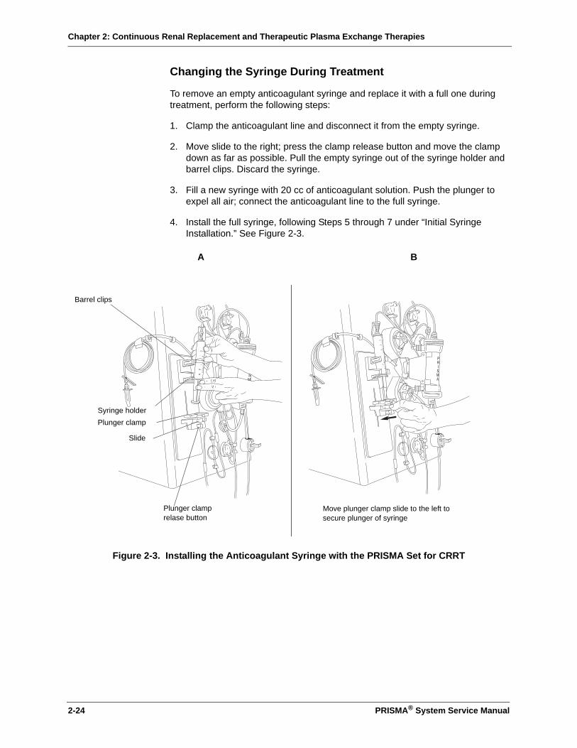
Chapter 2: Continuous Renal Replacement and Therapeutic Plasma Exchange Therapies
2-24 PRISMA® System Service Manual
Changing the Syringe During Treatment
To remove an empty anticoagulant syringe and replace it with a full one during treatment, perform the following steps:
1. Clamp the anticoagulant line and disconnect it from the empty syringe.
2. Move slide to the right; press the clamp release button and move the clamp down as far as possible. Pull the empty syringe out of the syringe holder and barrel clips. Discard the syringe.
3. Fill a new syringe with 20 cc of anticoagulant solution. Push the plunger to expel all air; connect the anticoagulant line to the full syringe.
4. Install the full syringe, following Steps 5 through 7 under “Initial Syringe Installation.” See Figure 2-3.
Figure 2-3. Installing the Anticoagulant Syringe with the PRISMA Set for CRRT
A B
Slide
Barrel clips
Syringe holderPlunger clamp
Plunger clamprelase button
Move plunger clamp slide to the left to secure plunger of syringe

Chapter 2: Continuous Renal Replacement and Therapeutic Plasma Exchange Therapies
PRISMA® System Service Manual 2-25
Change Bags Function
Any of the bags in use can be changed at any time during a patient treatment (Run mode), not just when a Bag Empty/Bag Full alarm occurs. This is done by using the Change Bags function available on the More Softkeys screen.4
Control Unit Actions
When Change Bags on the More Softkeys screen is pressed, the following control unit actions occur:
• Blood and anticoagulant pumps continue to operate; all other pumps stop.
• Yellow status light illuminates as a reminder that therapy is not being delivered.
• Audible alarm sounds as a reminder that therapy is not being delivered.
• Change Bags screen appears and provides on-line instructions.
Changing a Bag During Treatment
To change a bag during treatment, perform the following steps.
1. On the Status screen, press More Softkeys, then press Change Bags to access the Change Bags screen.
2. Press the Mute key to silence the audible alarm.
3. Clamp the line of the set that is connected to the bag to be changed.
4. Clamp the bag and disconnect it from the line.
5. Hang a new bag on the scale hook and connect it to the line.
6. Unclamp the new bag and line.
7. Verify that all lines to bags in use are unclamped and that all unused lines remain clamped.
8. Press Status to return to the Status screen and resume the patient treatment.
Pressure Monitoring
The PRISMA Control Unit has an integral pressure monitoring system providing noninvasive assessment of the access, return, and effluent lines, and the filter.
Monitoring provides notification to the operator of abnormal pressure conditions, such as extreme positive pressure in the return line.
Monitoring also provides data needed by PRISMA software to calculate other vital pressure conditions, such as transmembrane pressure (TMP) and filter pressure drop (∆P filter). These calculations are used to provide notification that clotting has begun in the filter or that the filter has clotted and the PRISMA Set must be changed.
4. The More Softkeys screen is accessed from the Status screen.
Chapter 2: Continuous Renal Replacement and Therapeutic Plasma Exchange Therapies
2-26 PRISMA® System Service Manual
Pressure Monitoring Components
Components of the pressure monitoring system include:
• Pressure pods. The PRISMA Set has a pressure pod in each of these locations: access line (access pod), return line (return pod), blood line immediately before the filter (filter pod), effluent line (effluent pod).
• Pressure sensor housings. The front panel of the control unit has four sensor housings. Their locations are shown in Figure 1-1 in Chapter 1: Introduction. The housings receive the pressure pods of the PRISMA Set and provide connection between the pods and the pressure sensors inside the control unit.
• Pressure sensors. A pressure sensor (transducer) is located inside the control unit, behind each pressure sensor housing.
Each pressure pod has a fluid compartment (top side) and an air compartment (bottom side). The compartments are separated by a flexible diaphragm, which normally rests in the middle of the pod, at the pressure “neutral” position. During a patient treatment, the fluid compartment of the pod is filled with the fluid flowing through the line to which the pod is attached.
Fluctuations in fluid pressure cause the diaphragm of the pod to move, compressing or expanding the air column on the other side of the diaphragm. The pressure sensor receives these fluctuations and converts them to electrical signals that are sent to PRISMA software and interpreted as a pressure value.
During operation, the pressure diaphragms can move slightly out of neutral position. The PRISMA Control Unit has an automatic reposition system (ARPS), located internally. The ARPS moves all diaphragms back to neutral position every 2 hours to ensure proper pressure monitoring. For more information, see “Automatic Reposition System” in Chapter 3: Electronic Description.
Pressures During Operation
Pressures vary within the PRISMA Set for CRRT, depending on individual patient characteristics (blood pressure, size, general condition, hematocrit), as well as size of the patient catheter, flow rates, and therapy being delivered. Current pressure at each pressure pod can be viewed on the Status screen during a patient treatment.
The following information is general and intended only to acquaint the service technician with broad pressure ranges that can be expected with use of the PRISMA System.
After priming is complete, do not remove the pressure pods from the pressure sensor housings. Pressure sensing becomes inaccurate if pods are removed, or if they are removed and then reinserted in the sensor housings. If pods are removed, the set must be changed or the Diaphragm Reposition procedure must be performed.
CAUTION
!
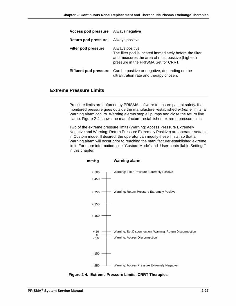
Chapter 2: Continuous Renal Replacement and Therapeutic Plasma Exchange Therapies
PRISMA® System Service Manual 2-27
Extreme Pressure Limits
Pressure limits are enforced by PRISMA software to ensure patient safety. If a monitored pressure goes outside the manufacturer-established extreme limits, a Warning alarm occurs. Warning alarms stop all pumps and close the return line clamp. Figure 2-4 shows the manufacturer-established extreme pressure limits.
Two of the extreme pressure limits (Warning: Access Pressure Extremely Negative and Warning: Return Pressure Extremely Positive) are operator-settable in Custom mode. If desired, the operator can modify these limits, so that a Warning alarm will occur prior to reaching the manufacturer-established extreme limit. For more information, see “Custom Mode” and “User-controllable Settings” in this chapter.
Figure 2-4. Extreme Pressure Limits, CRRT Therapies
Access pod pressure Always negative
Return pod pressure Always positive
Filter pod pressure Always positiveThe filter pod is located immediately before the filter and measures the area of most positive (highest) pressure in the PRISMA Set for CRRT.
Effluent pod pressure Can be positive or negative, depending on the ultrafiltration rate and therapy chosen.
- 250
+ 350
+ 450
+ 250
+ 150
- 150
0+ 10
- 10
+ 500
mmHg
Warning: Access Pressure Extremely Negative
Warning: Return Pressure Extremely Positive
Warning: Filter Pressure Extremely Positive
Warning: Set Disconnection; Warning: Return Disconnection
Warning: Access Disconnection
Warning alarm
Chapter 2: Continuous Renal Replacement and Therapeutic Plasma Exchange Therapies
2-28 PRISMA® System Service Manual
Pressure Operating Points
Whenever the PRISMA Control Unit is operating, a reference pressure value is stored in software memory for each pressure pod. This value is called the pressure operating point. Software continually compares the current pressure at each pod with the pressure operating point. In this way, the control unit can detect changing pressure conditions in the PRISMA Set and notify the operator with an Advisory alarm.
Initial Values
Operating points are initially established a short time after the control unit enters Run mode, when pumps have attained the proper speed and blood flow through the set is stabilized. The amount of time that elapses before all initial operating points are established depends on the operator-set blood flow rate, as shown below.
The initial operating points are established by recording the current pressure at each pressure pod at the end of the time periods shown above.
Note: The control unit cannot issue pressure Advisory alarms until the operating points are established.
Subsequent Values
During operation, certain events cause the control unit to reset (re-establish) all pressure operating points by again recording the current pressure at each pressure pod and storing the value in memory. This ensures that pressure monitoring remains accurate during the patient treatment.
Note: Operating points are re-established within 30 seconds. During this brief time, the control unit cannot issue pressure Advisory alarms.
Operating points are re-established whenever one or more of the following occurs:
1. After the blood pump changes speed during Run mode (due to operator changing the flow rate).
2. After the blood pump restarts (following an alarm or after pressing RESUME from the Stop screen).
3. After the operator presses the Continue softkey from a pressure trending Advisory alarm screen.
Blood flow rate Time to establish initial operating points
0 to 50 ml/min 4 minutes
55 to 100 ml/min 2 minutes
105 to 180 ml/min 90 seconds
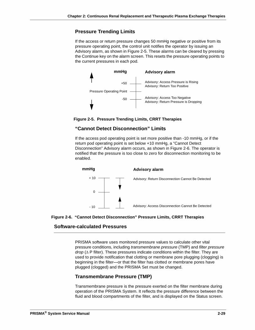
Chapter 2: Continuous Renal Replacement and Therapeutic Plasma Exchange Therapies
PRISMA® System Service Manual 2-29
Pressure Trending Limits
If the access or return pressure changes 50 mmHg negative or positive from its pressure operating point, the control unit notifies the operator by issuing an Advisory alarm, as shown in Figure 2-5. These alarms can be cleared by pressing the Continue key on the alarm screen. This resets the pressure operating points to the current pressures in each pod.
Figure 2-5. Pressure Trending Limits, CRRT Therapies
“Cannot Detect Disconnection” Limits
If the access pod operating point is set more positive than -10 mmHg, or if the return pod operating point is set below +10 mmHg, a “Cannot Detect Disconnection” Advisory alarm occurs, as shown in Figure 2-6. The operator is notified that the pressure is too close to zero for disconnection monitoring to be enabled.
Figure 2-6. “Cannot Detect Disconnection” Pressure Limits, CRRT Therapies
Software-calculated Pressures
PRISMA software uses monitored pressure values to calculate other vital pressure conditions, including transmembrane pressure (TMP) and filter pressure drop (∆ P filter). These pressures indicate conditions within the filter. They are used to provide notification that clotting or membrane pore plugging (clogging) is beginning in the filter—or that the filter has clotted or membrane pores have plugged (clogged) and the PRISMA Set must be changed.
Transmembrane Pressure (TMP)
Transmembrane pressure is the pressure exerted on the filter membrane during operation of the PRISMA System. It reflects the pressure difference between the fluid and blood compartments of the filter, and is displayed on the Status screen.
-50
+50
Pressure Operating Point
Advisory alarm
Advisory: Access Pressure is Rising
Advisory: Access Too Negative
Advisory: Return Too Positive
Advisory: Return Pressure is Dropping
mmHg
- 10
+ 10
0
Advisory: Access Disconnection Cannot Be Detected
Advisory: Return Disconnection Cannot Be Detected
Advisory alarmmmHg

Chapter 2: Continuous Renal Replacement and Therapeutic Plasma Exchange Therapies
2-30 PRISMA® System Service Manual
The TMP is calculated by PRISMA software as follows:
During a patient treatment, permeability of the membrane decreases due to protein coating on the blood side of the membrane. This causes the TMP to increase.
During operation, software sets the initial TMP value at the same time as the initial pressure operating points are established (shortly after entering Run mode). Thereafter, the initial TMP value is reset each time the blood flow, Patient Fluid Removal, or replacement solution rates are changed.
The amount of increase above the initial TMP value contributes to the Advisory: Filter Is Clotting alarm. This TMP parameter is settable only in Service mode by a trained and qualified person. For more information, see “Filter Pressure—Filter Is Clotting Advisory Limits” in the Specifications chapter. Additional information is available in Chapter 6: Alarm System and Troubleshooting.
If the TMP rises above +350 mmHg, the Advisory: TMP Too High alarm occurs. If desired, the operator can lower this Advisory alarm limit, so that the advisory occurs prior to reaching +350 mmHg. For more information, see “Custom Mode” and “User-controllable Settings” in this chapter. If the TMP increases beyond the membrane capacity of +450 mmHg, the Caution: TMP Excessive alarm occurs.
Filter Pressure Drop (∆P Filter)
Filter pressure drop, displayed on the Status screen, is a calculated value used to determine pressure conditions in the hollow fibers of the filter. Filter pressure drop is calculated by PRISMA software as follows:
During a patient treatment, microclotting can occur in the hollow fibers of the filter, eventually leading to gross clotting and the need to change to a new PRISMA Set. Clotting creates resistance as blood flows through the filter fibers and causes the filter pressure drop to increase.
The following example shows how filter pressure drop increases with filter use:
In the above example, filter pressure drop increased by 80 mmHg.
Filter Pressure + Return Pressure - Effluent Pressure2
TMP =
Filter pod pressure- Return pod pressure= Filter pressure drop
Filter pod pressure 100 mmHg 200 mmHg
Return pod pressure 90 mmHg 110 mmHg
Filter pressure drop 10 mmHg 90 mmHg
Begin Time After Filter Has Been in Use
-
=
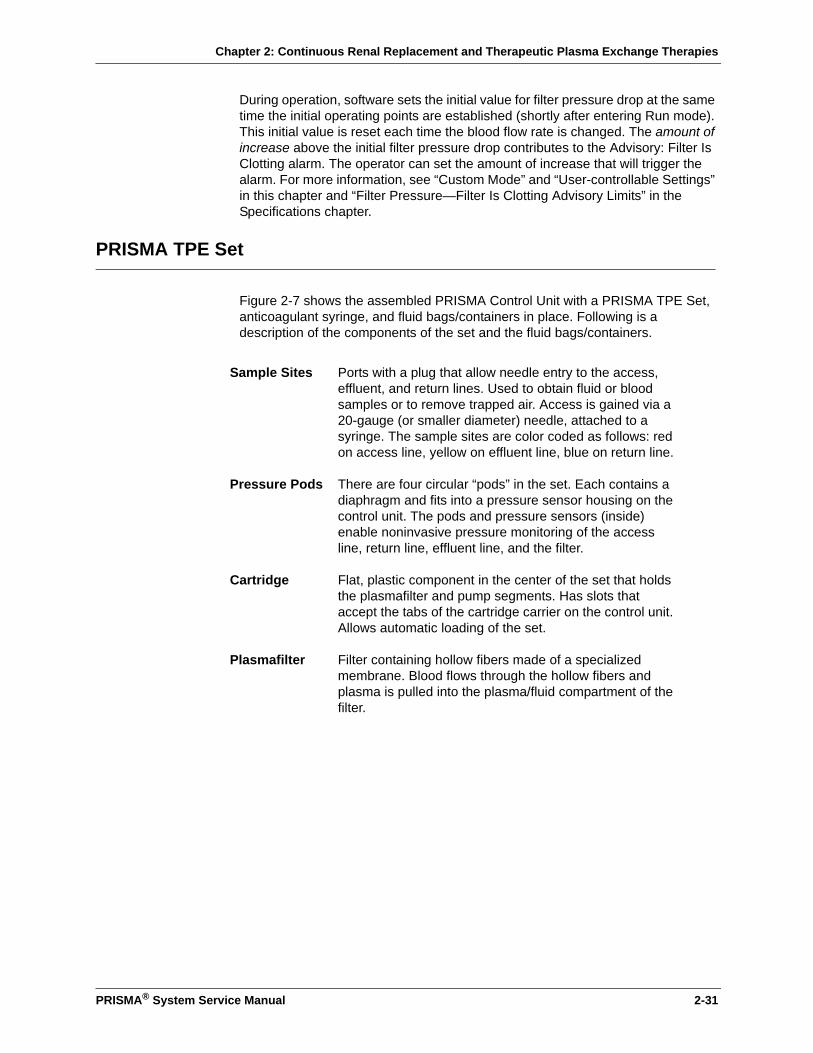
Chapter 2: Continuous Renal Replacement and Therapeutic Plasma Exchange Therapies
PRISMA® System Service Manual 2-31
During operation, software sets the initial value for filter pressure drop at the same time the initial operating points are established (shortly after entering Run mode). This initial value is reset each time the blood flow rate is changed. The amount of increase above the initial filter pressure drop contributes to the Advisory: Filter Is Clotting alarm. The operator can set the amount of increase that will trigger the alarm. For more information, see “Custom Mode” and “User-controllable Settings” in this chapter and “Filter Pressure—Filter Is Clotting Advisory Limits” in the Specifications chapter.
PRISMA TPE Set
Figure 2-7 shows the assembled PRISMA Control Unit with a PRISMA TPE Set, anticoagulant syringe, and fluid bags/containers in place. Following is a description of the components of the set and the fluid bags/containers.
Sample Sites Ports with a plug that allow needle entry to the access, effluent, and return lines. Used to obtain fluid or blood samples or to remove trapped air. Access is gained via a 20-gauge (or smaller diameter) needle, attached to a syringe. The sample sites are color coded as follows: red on access line, yellow on effluent line, blue on return line.
Pressure Pods There are four circular “pods” in the set. Each contains a diaphragm and fits into a pressure sensor housing on the control unit. The pods and pressure sensors (inside) enable noninvasive pressure monitoring of the access line, return line, effluent line, and the filter.
Cartridge Flat, plastic component in the center of the set that holds the plasmafilter and pump segments. Has slots that accept the tabs of the cartridge carrier on the control unit. Allows automatic loading of the set.
Plasmafilter Filter containing hollow fibers made of a specialized membrane. Blood flows through the hollow fibers and plasma is pulled into the plasma/fluid compartment of the filter.
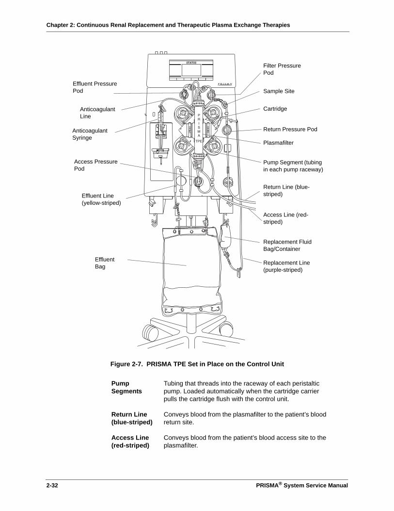
Chapter 2: Continuous Renal Replacement and Therapeutic Plasma Exchange Therapies
2-32 PRISMA® System Service Manual
Figure 2-7. PRISMA TPE Set in Place on the Control Unit
Pump Segments
Tubing that threads into the raceway of each peristaltic pump. Loaded automatically when the cartridge carrier pulls the cartridge flush with the control unit.
Return Line(blue-striped)
Conveys blood from the plasmafilter to the patient’s blood return site.
Access Line(red-striped)
Conveys blood from the patient’s blood access site to the plasmafilter.
Effluent Line(yellow-striped)
Anticoagulant Syringe
Anticoagulant Line
Sample Site
Replacement Line(purple-striped)
Pump Segment (tubing in each pump raceway)
Plasmafilter
Access Line (red-striped)
Return Line (blue-striped)
Return Pressure Pod
Replacement Fluid Bag/Container
Effluent Bag
Filter Pressure Pod
Access Pressure Pod
Effluent Pressure Pod
Cartridge
Chapter 2: Continuous Renal Replacement and Therapeutic Plasma Exchange Therapies
PRISMA® System Service Manual 2-33
System Overview with TPE
Communicating With the PRISMA Control Unit
The front panel of the PRISMA Control Unit has an electroluminescent display overlaid with a touchscreen. The display shows screens of written information. The touchscreen allows the operator to interact with the control unit by pressing various softkeys.
Interactive Display
During operation, different screens appear on the display, showing information about the treatment, giving steps the operator should take, and alerting the operator to any abnormal conditions. Specific display contents depend on the software mode and operating conditions at the moment. Some types of operating data, such as treatment history data, are only displayed when requested by the operator. The display is also a vehicle for servicing the system.
Softkeys are located along the sides and bottom of each screen. These allow the operator to give commands to the control unit and navigate between screens. The operator presses the desired softkey to initiate the function described by the softkey name.
The name and function of many of the softkeys change, depending on operating conditions. In this way, the operator is led through operating and alarm response situations.
Replacement Fluid Bag/Container
Holds prescribed replacement fluid.
Replacement Line (purple-striped)
Conveys replacement fluid from the replacement bag/container to the blood flowpath in the return line. Replacement is delivered post-dilution (just beyond the plasmafilter blood outlet).
Effluent Bag Collects removed plasma. One effluent bag is supplied with each set.
Effluent Line (yellow-striped)
Conveys removed plasma from the plasma/fluid compartment of the filter to the effluent bag.
Anticoagulant Line
Conveys anticoagulant solution from the anticoagulant syringe to the blood flowpath.
Chapter 2: Continuous Renal Replacement and Therapeutic Plasma Exchange Therapies
2-34 PRISMA® System Service Manual
User-controllable Settings
In order to administer the specific patient treatment prescribed by the physician, the operator controls many of the control unit’s settings. For example, pump flow rates, the Patient Plasma Loss rate, and anticoagulant settings. (Other settings are controlled only by the manufacturer or by trained and qualified service technicians.)
Table 2-16 in this chapter lists all user-controllable settings, their default values, setting options, and the mode in which they can be changed.
Default Values
There are default values for each setting. These are initially set by the manufacturer. The following information pertains to default values:
• The default value controls operation, unless the operator sets a new value during setup or administration of a treatment.
• All settings revert to their default values whenever a New Patient procedure is chosen.
• If desired, the operator can change the default values for the PRISMA therapies. This can only be done in Custom mode. For more information, see “Custom Mode” in this chapter.
Current Values
Current values are those that control operation during a patient treatment.
When the operator chooses a particular therapy during the Setup procedure, the control unit uses the default values assigned to that therapy. If desired, the operator can reset some of these values during the Setup procedure (Setup mode) or while the patient treatment is underway (Run mode). Any changes made in Setup or Run modes apply only to that treatment and do not affect the default values5.
Pumps
The control unit has four occlusive, peristaltic pumps. These include the blood, replacement fluid, dialysate (not active for TPE), and effluent pumps. The control unit has one syringe pump that delivers anticoagulant solution to the blood flow, if desired.
During a patient treatment (Run mode), the peristaltic pumps turn counterclockwise. During priming of the PRISMA TPE Set (Setup mode), some of the pumps turn clockwise. If the blood pump stops for any reason during treatment, all other pumps also stop. When the blood pump resumes, the other pumps also resume after a short delay.
The PRISMA software controls the speeds of the peristaltic pumps.
5. An exception is the setting “Language.” Changing the language in Run mode also changes the default language.
Chapter 2: Continuous Renal Replacement and Therapeutic Plasma Exchange Therapies
PRISMA® System Service Manual 2-35
The blood pump speed is based solely on the operator-set blood flow rate. The replacement and effluent pump speeds are based on all operator-set flow rates, as well as on the changing weights of fluid bags/containers in use. In this way, desired flow rates are constantly maintained.
TPE Prescription, Flow Rates, and Anticoagulant Settings
The TPE Prescription consists of three settings: Pre-treatment Hematocrit, Total Replacement Input, and Replacement Container Volume (volume of replacement fluid in the container).
Flow rates are the settings that control the rate of blood flow, patient plasma loss, replacement fluid infusion, and effluent flow during a patient treatment.
Below is the formula that governs the effluent pump rate:
Anticoagulant settings are those that control delivery of anticoagulant solution to the blood flow, if anticoagulation is desired. These settings include the Delivery Method (Continuous or Bolus), Delivery Rate (applicable only for Continuous delivery), Bolus Volume and Bolus Interval (applicable only for Bolus delivery).
All of the above settings are user-settable.
Adjusting the TPE Prescription, Flow Rates, and Anticoagulant Settings
During the Setup procedure (Setup mode), the Set TPE Prescription screen is displayed first and the Set Flow Rates screen is displayed next. The operator is asked to review the default TPE Prescription settings, flow rates, and anticoagulant settings, then make any changes desired for the current treatment.
Note: There is no default value for the Replacement Container Volume. The volume of fluid in the replacement container must be entered every treatment.
During the patient’s treatment (Run mode), the operator can access the Set Flow Rates screen and adjust the flow rates, anticoagulant settings, and TPE Prescription settings as needed. See “Operating Modes” and “User-controllable Settings” in this chapter for more information.
If desired, the operator can change the default flow rates, anticoagulant settings, and TPE Prescription settings in Custom mode. See “Custom Mode” in this chapter.
Patient Plasma Loss Rate
The Patient Plasma Loss rate is the net amount of plasma the PRISMA System removes from the patient each hour (after accounting for any replacement fluid being used). If the Patient Plasma Loss rate is set above zero, a net plasma loss occurs, resulting in a negative plasma balance in the patient.
Patient Plasma Loss rate (ml/hr)+ Replacement solution rate (ml/hr) = Effluent rate (ml/hr) set by PRISMA software

Chapter 2: Continuous Renal Replacement and Therapeutic Plasma Exchange Therapies
2-36 PRISMA® System Service Manual
In most TPE treatments, the physician prescribes a zero net plasma loss; therefore, in most cases the Patient Plasma Loss rate is set to 0 ml/hr.
Software Calculations of Target Patient Plasma Loss
PRISMA software calculates a Target Patient Plasma Loss for each TPE treatment, based on settings entered by the operator. This calculated value is displayed on the Set TPE Prescription and Set Flow Rates screens.
PRISMA software calculates the Target Patient Plasma Loss by first determining the treatment time according to the formula below.
Target Patient Plasma Loss is then calculated as follows:
If the Total Replacement Input, Replacement Fluid rate, or Patient Plasma Loss rate is changed during a treatment, the Target Patient Plasma Loss also changes.
Note: The Target Patient Plasma Loss for the treatment must be the same number as the net plasma loss prescribed by the physician, whether this is zero or a number above zero.
Setting the Patient Plasma Loss Rate to Achieve Prescribed Target Loss
If the prescribed net plasma loss is above zero, the operator must enter this volume as the Target Patient Plasma Loss value. This is done during the Setup procedure by performing the steps below (in the order listed).
1. On the Set TPE Prescription screen, enter the prescribed Total Replacement Input. Press CONTINUE to proceed to the Set Flow Rates screen.
2. On the Set Flow Rates screen, enter the prescribed Replacement Fluid rate. When the calculated Target Patient Plasma Loss appears, adjust the Patient Plasma Loss rate (up or down) until the calculated loss equals the physician-prescribed net plasma loss.
Setting the "Excess Pt. Fluid Loss or Gain" 6Safety Limit
A safety limit ensures that excessive fluid/plasma cannot be unintentionally removed from or infused to the patient across the semipermeable membrane of the filter. This limit protects the patient during abnormal conditions in which the effluent pump can be manually commanded to run.To correlate the safety limit to the individual patient, during the Setup procedure, the operator is asked to enter the physician-prescribed "Excess Pt. Fluid Loss or
6. “Pt. Fluid Loss or Gain” matches “Patient Plasma loss” in TPE treatment.
Volume to replace (Total Replacement Input [ml])Replacement fluid rate (ml/hr)
Treatment time =
Patient plasma loss rate x Treatment timeTarget patient plasma loss =
Chapter 2: Continuous Renal Replacement and Therapeutic Plasma Exchange Therapies
PRISMA® System Service Manual 2-37
Gain Limit"7.
The limit controls the amount of excess patient fluid loss or gain that is allowed within the last 3 hours; the limit may be set between 130 and 400 ml.
If the limit is reached, an alarm occurs that disables all fluid pumps from further use and requires the operator to end the treatment. For more information, see "Operating Modes" and "User-controllable Settings" in this chapter, and Appendix C: Fluid Balance Description (TPE).
Plasma Balance
Actual Patient Plasma Loss
Actual Patient Plasma Loss is the net amount of plasma removed from the patient by the PRISMA System since the start of treatment. In most TPE treatments, the physician prescribes a zero net plasma loss.
Measuring Actual Patient Plasma Loss
The replacement scale and effluent scale mounted on the bottom of the PRISMA Control Unit support the replacement fluid bag/container and effluent bag and constantly measure their weights. The change in combined weight of the fluid bags/containers in use indicates how much plasma has been removed from the patient by the control unit. When fluid bags/containers are replaced, the software automatically accounts for their new weights. The following formula applies:
Viewing Actual Patient Plasma Loss
During a patient treatment (Run mode), the Actual Patient Plasma Loss is displayed and continuously updated on the Status screen. It is also displayed on the Treatment History screen. The Treatment History screen is available for viewing during a treatment (Run mode) and when ending a treatment (End mode).
On the Treatment History screen, the operator can view the amount of Actual Patient Plasma Loss for the entire treatment or for a specified period of time during the treatment. See “Treatment History Data” in this chapter for more information.
Treatment Data
Certain Treatment Data continually update and display on the Status screen during a TPE treatment (Run mode). Data accumulates for the entire treatment period.
In addition to being displayed on the Status screen during a treatment, the
7. The "Excess Pt. Fluid Loss or Gain Limit" must be prescribed by the physician. The value prescribed should be based upon the patient's ability to tolerate potential fluid imbalance.
Change in Effluent Bag weight- Change in Repl. Bag/container weight=Actual patient plasma loss

Chapter 2: Continuous Renal Replacement and Therapeutic Plasma Exchange Therapies
2-38 PRISMA® System Service Manual
Treatment Data also accumulate and are stored minute-by-minute in the treatment history memory.
See “Treatment History Data” in this chapter for more information.
The Treatment Data displayed on the Status screen include the following:
• Replacement Fluid Input
• Effluent Volume (total plasma volume removed)
• Actual Patient Plasma Loss (net plasma volume removed)
Treatment History Data
Vital machine conditions and operating data are stored and updated minute-by-minute in software memory. The memory stores a full TPE treatment or up to 24 hours of treatment data, whichever is less. The old data are deleted and the new data are added minute-by-minute. The history data can be viewed on the Treatment History screen and on the Events screen. These screens are available during a treatment (Run mode) and when ending a treatment (End mode). History data for the last treatment can be viewed from the Choose Patient screen (Setup mode).
Treatment History
Cumulative totals for the Treatment Data displayed on the Status screen are stored and displayed on the Treatment History screen. Data for the history time period are displayed when the operator first brings the Treatment History screen to the display.
The operator can change the time period on the Treatment History screen by using the arrow softkeys. In this way, the operator can view fluid totals for all or a portion of the last 24 hours of treatment.
Events History
Certain events that may occur during setup and delivery of a treatment are stored and displayed on the Events screen.
The control unit stores the hour and minute that events occur, as well as the name of the event. Up to 100 events can be stored.
An event is recorded when any of the following occur:
• Excess Pt. Fluid Loss or Gain Limit, therapy, flow rates, and anticoagulant settings are initially selected (Setup mode).
• Prime test is passed.
• Treatment is started (Run mode).
• A flow rate or anticoagulant setting is changed during treatment.
• Replacement container volume, pre-treatment hematocrit, or total replacement input are changed.
• Replacement container is changed.
• TMPa self-calibration values are determined.
Chapter 2: Continuous Renal Replacement and Therapeutic Plasma Exchange Therapies
PRISMA® System Service Manual 2-39
• The sensitivity of the blood leak detector is normalized.
• An alarm occurs.
• An alarm screen is cleared from the display.
• Any of these softkeys are pressed: LOAD, PRIME, STATUS (when pressed on the Change Bags screen), CHANGE BAGS, RESUME, STOP, UNLOAD.
History Data After a Treatment
After a treatment is concluded, the treatment history data is stored in memory. It can be viewed from the Choose Patient screen (Setup mode) by pressing the Last Treatment History softkey. The Last Treatment History data is deleted when the NEW PATIENT softkey is pressed, as well as any time the date or time is changed in Custom mode.
History Data During a Power Loss
If a power loss occurs during a treatment, the treatment history data is retained in memory.
Alarm Safety System
The PRISMA Control Unit continually monitors itself and the PRISMA Set for abnormal conditions. Depending on the circumstance, the operator is alerted by the following:
• Red or yellow status light
• Audible alarm
• Alarm screen on the display, giving instructions for responding to the abnormal condition
Alarms are prioritized into Warning, Malfunction, Caution, and Advisory alarms. See Chapter 6: Alarm System and Troubleshooting for more information.
Monitoring Systems
Pressure
The PRISMA Control Unit has an integral pressure monitoring system. The system alerts the operator (via alarms) to abnormal pressure conditions, such as extreme positive pressure in the return line or clotting in the filter. See the “Pressure Monitoring” section of this chapter for more information.
Blood Leak
The PRISMA Control Unit has an infrared blood leak detector that monitors the effluent line for blood. If blood is detected, the operator is notified via a warning alarm which stops the blood pump and closes the return line clamp. See Chapter 3: Electronic Description for more information.
Air Bubble
The PRISMA Control Unit has an ultrasonic air bubble detector that continually

Chapter 2: Continuous Renal Replacement and Therapeutic Plasma Exchange Therapies
2-40 PRISMA® System Service Manual
monitors the return line for the presence of macro and micro air bubbles. If air is detected, the operator is notified via a warning alarm that stops the blood pump and closes the return line clamp See Chapter 3: Electronic Description for more information.
TPE Operation
Startup
Startup of the PRISMA Control Unit consists of the following steps:
1. Operator turns the power switch to the “on” position.
2. The control unit performs an initialization test to check the system electronics. The Logo screen is displayed, the non-mutable buzzer sounds, and all status lights are illuminated during the test.
3. When the initialization test is successfully completed, the Choose Patient screen appears on the display and the yellow status light illuminates. This indicates the PRISMA Control Unit is in the Setup mode and is ready for operation.
Note: The above actions occur when a new PRISMA Control Unit is initially turned on. These actions also occur whenever the unit is turned on after being turned off in the Treatment Complete screen. If the control unit was last turned off in a screen other than Treatment Complete, a Query screen appears after the initialization test is completed. From the Query screen, the operator can choose one of two actions:
• Begin on the same operating screen as when the unit was turned off (by pressing the Continue key).
• Start over at the Choose Patient screen (by pressing the Restart key).
Control and Navigation
The PRISMA Control Unit is operated by means of the interactive display on the upper front panel. The screens displayed lead the operator through the operating procedures. Help screens provide additional information, if needed. The softkeys that appear on each screen enable the operator to give commands to the control unit and navigate between screens.
If the display goes blank while power is on, immediately terminate the treatment and service the control unit.
WARNING
!
Chapter 2: Continuous Renal Replacement and Therapeutic Plasma Exchange Therapies
PRISMA® System Service Manual 2-41
Screen Layout
Screens (text and softkeys) displayed by the PRISMA Control Unit have the following landmarks:
• The upper left corner shows the operating modes of the PRISMA Control Unit, with the current mode highlighted.
• The upper right corner shows the PRISMA therapies with the current therapy highlighted.
• The far right softkey of Operating and Alarm screens is labeled Help. Pressing this key provides more detail about the displayed screen.
• The far right softkey of Help screens is labeled Exit Help. Pressing this key allows the operator to return to the screen that was displayed when Help was pressed.
• An Examine Alarms key appears above the Help key whenever an alarm occurs, whenever the operator overrides an alarm, or whenever one or more lower-priority alarms are pending during an alarm. For more information, see Chapter 6: Alarm System and Troubleshooting.
• Arrows appear on certain screens. These enable the operator to adjust settings. For example, arrows are used to set the flow rates or view a certain time period within the treatment history data. By pressing and holding the arrows, the operator can scroll through the available options. By pressing and releasing the arrows, the operator can make fine adjustments.
Operating Modes
In the course of performing a treatment, the control unit passes through four normal Operating modes: Setup, Standby, Run, and End. Following is a description of each of the Operating modes.
Setup Mode
The control unit automatically goes into Setup mode after successful completion of the initialization test. Setup mode enables the operator to load the PRISMA TPE Set onto the control unit, prepare and connect needed solutions, and prime the set.
While the control unit is in Setup mode, appropriate alarms are enabled and the yellow status light is illuminated.
The operator follows the instructions on the display to perform the following sequential actions:
1. Enter Custom mode, if desired, to alter default settings of one or more PRISMA therapies. See “Custom Mode” in this chapter for more information.
2. View treatment history data of the last treatment.
3. Choose New Patient or Same Patient.

Chapter 2: Continuous Renal Replacement and Therapeutic Plasma Exchange Therapies
2-42 PRISMA® System Service Manual
If New Patient is chosen, the control unit deletes the treatment history data of the last treatment and advances to the Set Excess Pt. Fluid Loss or Gain Limit screen.If Same Patient is chosen, the control unit retains the treatment history data of the last treatment, retains the last chosen therapy and all its setting values, and advances to the Load Set screen (described in Step 6 below).
Note: The replacement fluid container in use can remain in use until empty. The therapy cannot be changed to CRRT. This can only be done through New Patient, which erases all treatment history data.
When the Same Pt. treatment starts (Run mode), the cumulative count for "Excess Patient Fluid Loss or Gain" over the last 3 hours begins again at 0 ml.
4. Review/adjust the Excess Pt. Fluid Loss or Gain Limit. (Enter the physician-prescribed value).
5. Choose TPE therapy. The control unit accesses the default settings and screens for TPE therapy.
6. Position the PRISMA TPE Set onto the control unit. This includes (a) placing the cartridge of the set in the cartridge carrier, (b) routing lines of the set through tubing guides, air detector, and blood leak detector, (c) hanging the effluent bag on the effluent scale hook, and (d) attaching the pressure pods to the pressure sensor housings. See Figure 2-9.
7. Automatically load the set by pressing the Load softkey. When Load is pressed, the pumps begin turning, the set is drawn inward, and the pump segments of the set are threaded into the pump raceways.
8. Prepare and connect replacement fluid and priming solution;
SPECIAL PROCEDURE WHEN USING THE ACCESSORY SP394 WITH THE PRISMA SYSTEM IN TPE MODE
This device can be used to connect together several containers (bags or bottles) of replacement fluid for the TPE therapy. (see figure 2-8)
a) The end of the line equipped with the vented spike (accessory with blue cap) must be connected to the first bottle or the first bag. Then the other end of the line has to be connected to the second bag or bottle.
b) The second segment of line is used to connect together the second bag or bottle to the third one.
c) The third bottle or the third bag is then connected to the replacement fluid line of the PRISMA TPE SET via the spike or the luer-lock connector.
Ensure that the proper PRISMA Set has been chosen for the selected therapy. Using the wrong set for the therapy can cause patient injury or death.WARNING
!
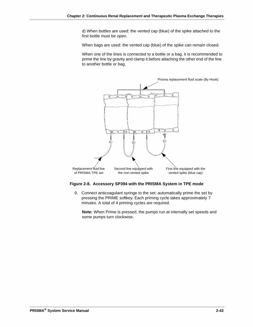
Chapter 2: Continuous Renal Replacement and Therapeutic Plasma Exchange Therapies
PRISMA® System Service Manual 2-43
d) When bottles are used: the vented cap (blue) of the spike attached to the first bottle must be open.
When bags are used: the vented cap (blue) of the spike can remain closed.
When one of the lines is connected to a bottle or a bag, it is recommended to prime the line by gravity and clamp it before attaching the other end of the line to another bottle or bag.
Figure 2-8. Accessory SP394 with the PRISMA System in TPE mode
9. Connect anticoagulant syringe to the set; automatically prime the set by pressing the PRIME softkey. Each priming cycle takes approximately 7 minutes. A total of 4 priming cycles are required.
Note: When Prime is pressed, the pumps run at internally set speeds and some pumps turn clockwise.
Second line equipped with the non-vented spike
Replacement fluid line of PRISMA TPE set
First line equipped with the vented spike (blue cap)
Prisma replacement fluid scale (By Hook)
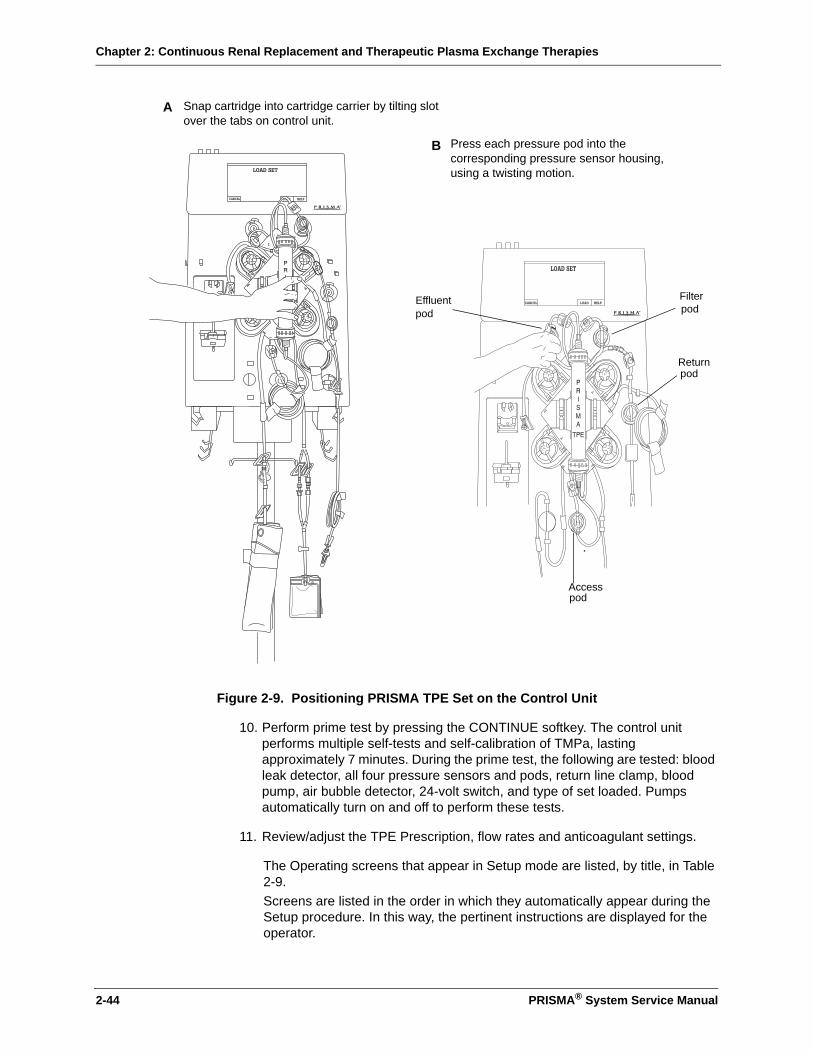
Chapter 2: Continuous Renal Replacement and Therapeutic Plasma Exchange Therapies
2-44 PRISMA® System Service Manual
Figure 2-9. Positioning PRISMA TPE Set on the Control Unit
10. Perform prime test by pressing the CONTINUE softkey. The control unit performs multiple self-tests and self-calibration of TMPa, lasting approximately 7 minutes. During the prime test, the following are tested: blood leak detector, all four pressure sensors and pods, return line clamp, blood pump, air bubble detector, 24-volt switch, and type of set loaded. Pumps automatically turn on and off to perform these tests.
11. Review/adjust the TPE Prescription, flow rates and anticoagulant settings.
The Operating screens that appear in Setup mode are listed, by title, in Table 2-9. Screens are listed in the order in which they automatically appear during the Setup procedure. In this way, the pertinent instructions are displayed for the operator.
Snap cartridge into cartridge carrier by tilting slot over the tabs on control unit.
Press each pressure pod into the corresponding pressure sensor housing, using a twisting motion.
B
A
Filterpod
Returnpod
Accesspod
Effluent pod

Chapter 2: Continuous Renal Replacement and Therapeutic Plasma Exchange Therapies
PRISMA® System Service Manual 2-45
Note: If a screen is accessed from a prior-appearing screen, it is indented in the table.
Standby Mode
The control unit automatically goes into Standby mode after the operator completes all Setup procedures and presses the Continue softkey on the Set Flow Rates screen. The Connect Patient screen appears. The operator can connect the patient to the primed set at this time.
The control unit also enters Standby mode any time the Stop softkey is pressed during Run mode. The Stop screen appears and provides options to re-enter Run mode by pressing Resume, or proceed to End mode by pressing Change Set, End Treatment, or Temp Discon.
During Standby mode, all pumps are stopped, appropriate alarms are enabled, and the yellow status light is illuminated. The screens that appear in Standby
Table 2-9: TPE Operating Screens in Setup Mode
Choose Patient
Treatment History
Events
Confirm New Patient
Set Excess Pt. Fluid Loss or Gain Limit
Choose Therapy
Load Set
Loading pumps, please wait
Unloading pumps, please wait(for use if loading was unsuccessful)
Prepare Solutions
Connect Lines to Solutions
Priming, please wait
XX of 4 Prime Cycles Complete
Prime Test, please wait
Prime Test Passed
Set TPE Prescription
Set Flow Rates
Modify Anticoag
• If a patient is not connected to the PRISMA TPE Set shortly after priming is complete, flush the set with at least 250 ml priming solution (saline with heparin added) before connecting a patient.
• All lines in the PRISMA TPE Set have a preattached slide clamp. Clamp the anticoagulant line (if not in use) after priming is complete.
WARNING
!
Chapter 2: Continuous Renal Replacement and Therapeutic Plasma Exchange Therapies
2-46 PRISMA® System Service Manual
mode are listed in Table 2-10.
Run Mode
The control unit enters Run mode after the operator connects the patient to the primed set and presses the START softkey from the Connect Patient screen.
During Run mode, all appropriate alarms are enabled and the green status light is illuminated, unless an alarm occurs or the Change Bags screen is displayed.
The Status screen is the first Run mode screen and is normally displayed during the entire patient treatment. From the Status screen, the operator can access all the other Run mode screens. Run mode allows the operator to perform the following actions:
1. Administer the treatment to the patient. The fluid pumps operate according to default settings or those entered by the operator. Bag weights are monitored and treatment data is accumulated and stored.
2. Adjust TPE flow rates, TPE Prescription, anticoagulant settings, and the Patient Plasma Loss rate, as needed.
3. Change bags at any time through the Change Bag function.
4. Adjust Status screen settings, which include the Pressure Display, Flow Rate Display, and Language.
5. View treatment history data.
6. Reset (re-normalize) the sensitivity of the blood leak detector, if needed.
7. Temporarily stop the patient’s treatment by pressing the Stop softkey.
Table 2-10: TPE Operating Screens in Standby Mode
Connect Patient
Stop
A new replacement container volume must be entered if the replacement container is changed during a treatment. This is done by pressing the softkey labeled “Replcmnt Container Volume” on the Change Bags screen.
The blood leak detector must be re-normalized if the effluent line is repositioned or removed and then reinserted into the blood leak detector after treatment (Run mode) has started. This is done by pressing the Normalize BLD softkey on the More Softkeys screen. The detector must be re-normalized before continuing a patient treatment.
CAUTION
!
WARNING
!

Chapter 2: Continuous Renal Replacement and Therapeutic Plasma Exchange Therapies
PRISMA® System Service Manual 2-47
The Operating screens available in Run mode are listed in Table 2-11. If a screen is accessed from a prior-appearing screen, it is indented in the table.
End Mode
The control unit enters End mode when the operator presses Stop, then presses the Change Set, End Treatment, or Temp Discon softkey. Appropriate alarms are enabled and the yellow status light is illuminated.
End mode allows the operator to perform the following procedures:
1. Change Set (remove the present PRISMA TPE Set, with or without returning blood to the patient, and load a new set).
2. End Treatment (terminate the present treatment, with or without returning blood to the patient, and view treatment history data before turning off the machine).
3. Temporary Disconnection (temporarily disconnect the patient from the set).
Following is a description of the operator and machine actions that occur in each End mode procedure.
Change Set Procedure
After pressing Change Set, the operator follows the instructions displayed to perform the following actions:
1. Return blood to the patient, if desired—by pressing the Return Blood softkey and following the instructions on the Return Blood screen, or by returning blood manually.
Note: The blood pump automatically runs at 110 ml/min when the Return Blood softkey is pressed. If a slower blood return rate is desired, the operator must return blood manually (by powering the machine off and turning the blood pump counterclockwise, as described in “Manual Termination of Treatment” in Chapter 6: Alarm System and Troubleshooting).
Table 2-11: TPE Operating Screens in Run Mode
Status
Set Flow Rates
Modify Anticoag
Set TPE Prescription
More Softkeys
Treatment History
Events
Change Bags
Test Effluent Line for Blood
Normalize Blood Leak Detector
Modify Settings
Chapter 2: Continuous Renal Replacement and Therapeutic Plasma Exchange Therapies
2-48 PRISMA® System Service Manual
2. Disconnect the patient from the set and disconnect the clear segment of the access line from the saline bag, if applicable. Unload the pump segments by pressing the Unload softkey. Remove the set and return to the Load Set screen in Setup mode.
3. Place a new PRISMA TPE Set on the control unit and load the set by pressing the Load softkey. Treatment continues once the control unit reaches Run mode.
Note: When selecting return blood to the patient or patient disconnection, the cumulative count for "Excess Pt. Fluid Loss or Gain" over the last 3 hours starts over at 0 ml.
The “Change Set” screens available in End mode are listed in Table 2-12.
End Treatment Procedure
After pressing END TREATMENT, the operator follows the instructions displayed to perform the following actions:
1. Return blood to the patient, if desired—by pressing the Return Blood softkey and following the instructions on the Return Blood screen, or by returning blood manually.
Note: The blood pump automatically runs at 110 ml/min when the Return Blood softkey is pressed. If a slower blood return rate is desired, the operator must return blood manually (by powering the machine off and turning the blood pump counterclockwise, as described in “Manual Termination of Treatment” in Chapter 6: Alarm System and Troubleshooting).
2. Disconnect the patient from the set and disconnect the clear segment of the access line from the saline bag, if applicable. Unload the pump segments by pressing the Unload softkey. (The control unit automatically advances to the Treatment Complete screen.)
3. Remove the set; view treatment history, if desired.
4. Turn off the control unit.
Ensure that the proper PRISMA Set has been loaded for the selected therapy. Using the wrong set for the therapy can cause patient injury or death.
Table 2-12: TPE “Change Set” Screens in End Mode
Change Set
Return Blood(optional)
Disconnect Patient
Unloading pumps, please wait
Remove Set
WARNING
!
Chapter 2: Continuous Renal Replacement and Therapeutic Plasma Exchange Therapies
PRISMA® System Service Manual 2-49
Note: When selecting return blood to the patient or patient disconnection, the cumulative count for "Excess Pt. Fluid Loss or Gain" over the last 3 hours starts over at 0 ml.
The “End Treatment” screens available in End mode are listed in Table 2-13.
Temporary Disconnection Procedure
After pressing Temp Discon, the operator follows the instructions displayed to perform the following actions:
1. Disconnect the red segment of the access line from the patient and connect it to a bag of sterile saline.
2. Return blood to the patient using the Start Return softkey to pump saline through the access line.
Note: If the set has significant clotting, the operator can choose to automatically unload it and cycle into the Change Set procedure. This can be done by pressing Continue without returning the patient’s blood, then pressing Unload when the “Temp Discon – Prepare to Prime” screen (Step 3 below) appears.
3. Disconnect the return line from the patient and connect it to a bag of priming solution. Disconnect the red segment of the access line from the saline bag and connect it to an empty collection bag.
4. Pump priming solution into the blood lines. (The control unit automatically returns to the Priming, Please Wait screen in Setup mode.)
5. Resume treatment by reconnecting the patient to the set and pressing the
6. Start softkey.
The “Temporary Disconnection” screens available in End mode are listed in Table 2-14
Table 2-13: TPE “End Treatment” Screens in End Mode
End Treatment
Return Blood(optional)
Disconnect Patient
Unloading pumps, please wait
Treatment Complete
Treatment History
Events
If a patient is not connected to the PRISMA TPE Set shortly after priming is complete, flush the set with at least 250 ml priming solution (saline with heparin added) before connecting a patient.WARNING
!
Chapter 2: Continuous Renal Replacement and Therapeutic Plasma Exchange Therapies
2-50 PRISMA® System Service Manual
Custom Mode
Custom mode allows the operator to change the default settings of the TPE therapy. To change a default setting, the operator follows the instructions on the display to perform the following steps:
1. Enter Custom mode by pressing Custom on the Choose Patient screen.
2. Choose the TPE therapy.
3. Review all user-controllable settings for the chosen therapy and change the default values, as desired.
Note: The new default values are stored in memory when the Exit Custom key is pressed from any screen.
The screens available in Custom mode are listed in Table 2-15.
User-controllable Settings
User-controllable settings and the mode in which they can be altered are listed in Table 2-16. Each setting has a default value and a range of setting options.
Some user-controllable settings, such as alarm limits, can only be adjusted in Custom mode. These settings are listed first in the table, followed by the settings that can be adjusted in Custom, Setup, and Run modes.
Table 2-14: TPE “Temporary Disconnection” Screens in End Mode
Temporary Disconnection
TEMP DISCON - Return Blood
TEMP DISCON - Prepare to Prime(first screen of instructions)
TEMP DISCON - Prepare to Prime(second screen of instructions)
Unloading pumps, please wait(optional, if set has significant clotting)
Table 2-15: TPE Screens in Custom Mode
Welcome to Custom Mode
Choose Therapy to Customize
Modify TPE Defaults
Clock
Modify Alarm Limits
Set Default TPE Prescription
Set Default Flow Rates
Modify Anticoag Defaults
Modify Settings
Chapter 2: Continuous Renal Replacement and Therapeutic Plasma Exchange Therapies
PRISMA® System Service Manual 2-51
The settings adjustable only in Custom and Run modes are listed last.
Table 2-16: User-controllable Settings in TPE Therapy
Setting Default Options
ChangeDefault
Change Present Treatment
Custom Setup Run
Clock A time set by the manufacturer.
Should always be set to current year, month, day, hour.
X
“Time to Change Set” Advisory Limit
After 72 hours of use. After 24 to 72 hours of use.Increment: 24 hours
X
“Access Pressure Extremely Negative” Warning Limit
-250 mmHg -15 to -250 mmHg Increment: 5 mmHg
X
“Return Pressure Extremely Positive” Warning Limit
+350 mmHg +15 to +350 mmHgIncrement: 5 mmHg
X
“TMPa Too High” Advisory Limit
+100 mmHg 0 to +100 mmHgIncrement: 1 mmHg
X
“Plasmafilter is Clotting” Advisory Limit
Filter pressure drop (∆P filter) is +100 mmHg greater than initial filter pressure drop (∆P filter).
+10 to +100 mmHg greater than initial filter pressure drop.Increment: 10 mmHg
X
“Excess Pt. Fluid Loss or Gain” Caution Limit
130 ml within 3 hours 130 to 400 mlIncrement: 10 ml
X
Anticoagulant Delivery Method
Continuous Continuous or Bolus X X X
Anticoagulant Continuous Delivery Rate
0 ml/hr 0, 0.5 to 5.0 ml/hrIncrement: 0.1 ml/hr
X X X
Anticoagulant Bolus Delivery Volume
0 ml 0, 0.5 to 5.0 mlIncrement: 0.1 ml
X X X
Anticoagulant Bolus Delivery Interval
Once every 6 hours. Once every 1 to24 hours.Increment: 1 hourNote: Immediate option also available in Run mode only.
X X X
Blood Flow Rate 10 ml/min 10 to 180 ml/minIncrement: 5 ml/min
X X X
Replacement Fluid Flow Rate
0 ml/hr 0, 100 to 2000 ml/hrIncrement: 10 ml/hr
X X X

Chapter 2: Continuous Renal Replacement and Therapeutic Plasma Exchange Therapies
2-52 PRISMA® System Service Manual
Pre-treatment Hematocrit
43% 10 to 60%Increment: 1%
X X X
Total Replacement Input
3000 ml 0 to 10,000 mlIncrement: 100 ml
X X X
Patient Plasma Loss Rate
0 ml/hr 0 to 1000 ml/hrIncrement: 10 ml/hr
X X X
Replacement Container Volume
N/A 0 to 5000 mlIncrement: 10 ml
X X X
Pressures Display on Status screen
On Off, On X X
Flow Rates Display on Status screen
On Off, On X X
Language R03.10.A:ENGLISH
R03.10.A:ENGLISH, FRENCH, GERMAN, DUTCH, ITALIAN, SPANISH, SWEDISH.
X Xa
Language R03.10.A1:ENGLISH
R03.10.A1:ENGLISH, FRENCH, GERMAN, SPANISH, SWEDISH, DANISH, PORTUGUESE.
X Xa
Language R03.10.A2:ENGLISH
R03.10.A2:ENGLISH, RUSSIAN.
X Xa
a. Changing the language in Run mode also changes the default language.
Table 2-16: User-controllable Settings in TPE Therapy
Setting Default Options
ChangeDefault
Change Present Treatment
Custom Setup Run

Chapter 2: Continuous Renal Replacement and Therapeutic Plasma Exchange Therapies
PRISMA® System Service Manual 2-53
Anticoagulant Syringe Installation Procedure
A 20-cc syringe should be filled and installed in the syringe pump during Setup mode, while the Prepare Solutions screen is on the display.
• If anticoagulation of the blood flowpath is desired, the syringe should be filled with anticoagulant solution.
• If anticoagulation is not desired, the syringe should be filled with priming solution. This assures the anticoagulant line will be primed during the automatic priming cycle.
During treatment, an Advisory alarm occurs whenever the anticoagulant syringe is empty. The empty syringe can be removed and a full one installed with no interruption in treatment.
Initial Syringe Installation
(See Figure 2-10)
To install the syringe into the syringe pump, perform the following steps.
1. Fill the syringe with 20 cc of anticoagulant solution (or priming solution if anticoagulation is not desired). Push the plunger of the syringe to expel all air.
2. Open the plunger clamp by moving the slide all the way to the right.
3. Push the plunger clamp release button while moving the plunger clamp down as far as possible.
4. Attach the luer lock connector of the anticoagulant line to the anticoagulant syringe.
5. Place the wing of the syringe into the syringe holder between the metal clip and plastic housing. Snap the barrel of the syringe between the barrel clips.
6. While pushing the plunger clamp release button, move the clamp up to the bottom of the plunger. Release the button.
• To assure proper anticoagulant flow control, use only 20-cc BD, Braun, Monoject, or Terumo luer lock syringes. The internal diameter of these syringes has been verified at the time of printing this manual. The manufacturer of the PRISMA System cannot be held liable for subsequent changes that may occur to syringe dimensions. See Anticoagulant Settings in the Specification chapter for verified internal diameters.
• Use only luer lock syringes with the PRISMA System. Use of non-luer lock syringes can result in patient blood loss if the anticoagulant line becomes dislodged from the syringe. See above for the list of approved syringes.
WARNING
!
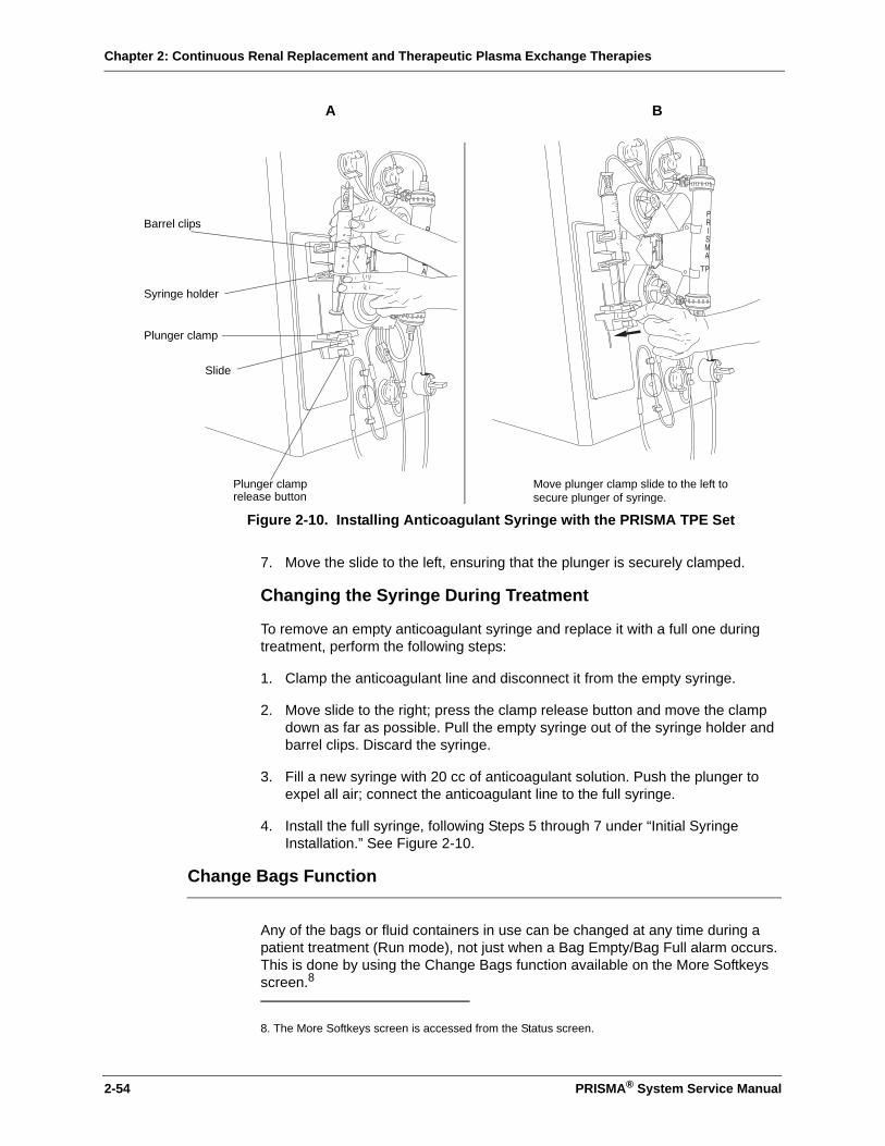
Chapter 2: Continuous Renal Replacement and Therapeutic Plasma Exchange Therapies
2-54 PRISMA® System Service Manual
7. Move the slide to the left, ensuring that the plunger is securely clamped.
Changing the Syringe During Treatment
To remove an empty anticoagulant syringe and replace it with a full one during treatment, perform the following steps:
1. Clamp the anticoagulant line and disconnect it from the empty syringe.
2. Move slide to the right; press the clamp release button and move the clamp down as far as possible. Pull the empty syringe out of the syringe holder and barrel clips. Discard the syringe.
3. Fill a new syringe with 20 cc of anticoagulant solution. Push the plunger to expel all air; connect the anticoagulant line to the full syringe.
4. Install the full syringe, following Steps 5 through 7 under “Initial Syringe Installation.” See Figure 2-10.
Change Bags Function
Any of the bags or fluid containers in use can be changed at any time during a patient treatment (Run mode), not just when a Bag Empty/Bag Full alarm occurs. This is done by using the Change Bags function available on the More Softkeys screen.8
8. The More Softkeys screen is accessed from the Status screen.
A B
Plunger clamprelease button
Slide
Move plunger clamp slide to the left tosecure plunger of syringe.
Barrel clips
Syringe holder
Plunger clamp
Figure 2-10. Installing Anticoagulant Syringe with the PRISMA TPE Set
Chapter 2: Continuous Renal Replacement and Therapeutic Plasma Exchange Therapies
PRISMA® System Service Manual 2-55
Control Unit Actions
When Change Bags on the More Softkeys screen is pressed, the following control unit actions occur:
• Blood and anticoagulant pumps continue to operate; all other pumps stop.
• Yellow status light illuminates as a reminder that therapy is not being delivered.
• Audible alarm sounds as a reminder that therapy is not being delivered.
• Change Bags screen appears and provides on-line instructions.
Changing a Bag During Treatment
To change a bag during treatment, perform the following steps.
1. On the Status screen, press More Softkeys, then press Change Bags to access the Change Bags screen.
2. Press the Mute key to silence the audible alarm.
3. Clamp the line of the set that is connected to the bag to be changed.
4. Clamp the bag and disconnect it from the line.
5. Hang a new bag on the scale hook and connect it to the line.
6. Unclamp the new bag and line.
7. Verify that all lines to bags in use are unclamped and that all unused lines remain clamped.
8. If the replacement container has been changed, use the softkey labeled “Replcmnt Container Volume” to enter the new replacement container volume.
9. Press Status to return to the Status screen and resume patient treatment.
Pressure Monitoring
The PRISMA Control Unit has an integral pressure monitoring system providing noninvasive assessment of the access, return, and effluent lines, and the filter.
Monitoring provides notification to the operator of abnormal pressure conditions, such as extreme positive pressure in the return line or a too high TMPa.
Monitoring also provides data needed by PRISMA software to calculate other vital pressure conditions, such as filter pressure drop (∆P filter). These calculations are used to provide notification that clotting has begun in the plasmafilter or that the filter has clotted and the PRISMA TPE Set must be changed.
Chapter 2: Continuous Renal Replacement and Therapeutic Plasma Exchange Therapies
2-56 PRISMA® System Service Manual
Pressure Monitoring Components
Components of the pressure monitoring system include:
• Pressure pods. The PRISMA TPE Set has a pressure pod in each of these locations: access line (access pod), return line (return pod), blood line immediately before the filter (filter pod), effluent line (effluent pod).
• Pressure sensor housings. The front panel of the control unit has four sensor housings. Their locations are shown in Figure 1-1 in Chapter 1: Introduction. The housings receive the pressure pods of the PRISMA TPE Set and provide connection between the pods and the pressure sensors inside the control unit.
• Pressure sensors. A pressure sensor (transducer) is located inside the control unit, behind each pressure sensor housing.
Each pressure pod has a fluid compartment (top side) and an air compartment (bottom side). The compartments are separated by a flexible diaphragm, which normally rests in the middle of the pod, at the pressure “neutral” position. During a patient treatment, the fluid compartment of the pod is filled with the fluid flowing through the line to which the pod is attached.
Fluctuations in fluid pressure cause the diaphragm of the pod to move, compressing or expanding the air column on the other side of the diaphragm. The pressure sensor receives these fluctuations and converts them to electrical signals that are sent to PRISMA software and interpreted as a pressure value.
During operation, the pressure diaphragms can move slightly out of neutral position. The PRISMA Control Unit has an automatic reposition system (ARPS), located internally. The ARPS moves all diaphragms back to neutral position every 2 hours to ensure proper pressure monitoring.
Pressures During Operation
Pressures vary within the PRISMA TPE Set, depending on individual patient characteristics (blood pressure, size, general condition, hematocrit), as well as size of the patient catheter, and flow rates. Current pressure at each pressure pod can be viewed on the Status screen during a patient treatment.
The following information is general and intended only to acquaint the operator with broad pressure ranges that can be expected with use of the PRISMA System.
After priming is complete, do not remove the pressure pods from the pressure sensor housings. Pressure sensing becomes inaccurate if pods are removed, or if they are removed and then reinserted in the sensor housings. If pods are removed, the set must be changed or the Diaphragm Reposition procedure must be performed.
CAUTION
!

Chapter 2: Continuous Renal Replacement and Therapeutic Plasma Exchange Therapies
PRISMA® System Service Manual 2-57
.
Extreme Pressure Limits
Figure 2-11. Extreme Pressure Limits, TPE Therapy
Pressure limits are enforced by PRISMA software to ensure patient safety. If a monitored pressure goes outside the manufacturer-established extreme limits, a Warning or Caution alarm occurs. Warning alarms stop all pumps and close the return line clamp. Caution alarms allow the blood and anticoagulant pumps to continue operating while the remaining pumps stop; the return line clamp remains open. Figure 2-11 shows the manufacturer-established extreme pressure limits.
Two of the extreme pressure limits (Warning: Access Pressure Extremely Negative and Warning: Return Pressure Extremely Positive) are operator-settable in Custom mode. If desired, the operator can modify these limits, so that a Warning alarm will occur prior to reaching the manufacturer-established extreme limit. For more information, see “Custom Mode” and “User-controllable Settings” in this chapter.
Access pod pressure Always negative
Return pod pressure Always positive
Filter pod pressure Always positiveThe filter pod is located immediately before the filter and measures the area of most positive (highest) pressure in the PRISMA TPE Set.
Effluent pod pressure Can be positive or negative, depending on the plasma filtration rate.
- 250
+ 350
+ 450
+ 250
+ 150
- 150
0+ 10
- 10
+ 500
mmHg
Warning: Access Pressure Extremely Negative
Warning: Return Pressure Extremely Positive
Warning: Filter Pressure Extremely Positive
Warning: Set Disconnection; Warning: Return Disconnection
Warning: Access Disconnection
Warning/Caution alarm
- 50 Caution: Effluent Pressure too Negative
Chapter 2: Continuous Renal Replacement and Therapeutic Plasma Exchange Therapies
2-58 PRISMA® System Service Manual
Pressure Operating Points
Whenever the PRISMA Control Unit is operating, a reference pressure value is stored in software memory for each pressure pod. This value is called the pressure operating point. Software continually compares the current pressure at each pod with the pressure operating point. In this way, the control unit can detect and notify the operator of changing pressure conditions in the PRISMA TPE Set.
Initial Values
Operating points are initially established a short time after the control unit enters Run mode, when pumps have attained the proper speed and blood flow through the set is stabilized. The amount of time that elapses before all initial operating points are established depends on the operator-set blood flow rate, as shown below.
The initial operating points are established by recording the current pressure at each pressure pod at the end of the time periods shown above.
Note: The control unit cannot issue pressure Advisory alarms until the operating points are established.
Subsequent Values
During operation, certain events cause the control unit to reset (re-establish) all pressure operating points by again recording the current pressure at each pressure pod and storing the value in memory. This ensures that pressure monitoring remains accurate during the patient treatment.
Note: Operating points are re-established within 30 seconds. During this brief time, the control unit cannot issue pressure Advisory alarms.
Operating points are re-established whenever one or more of the following occurs:
1. After the blood pump changes speed during Run mode (due to operator changing the flow rate).
2. After the blood pump restarts (following an alarm or after pressing Resume from the Stop screen).
3. After the operator presses the Continue softkey from a pressure trending Advisory alarm screen.
Blood flow rate Time to establish initial operating points
0 to 50 ml/min 4 minutes
55 to 100 ml/min 2 minutes
105 to 180 ml/min 90 seconds
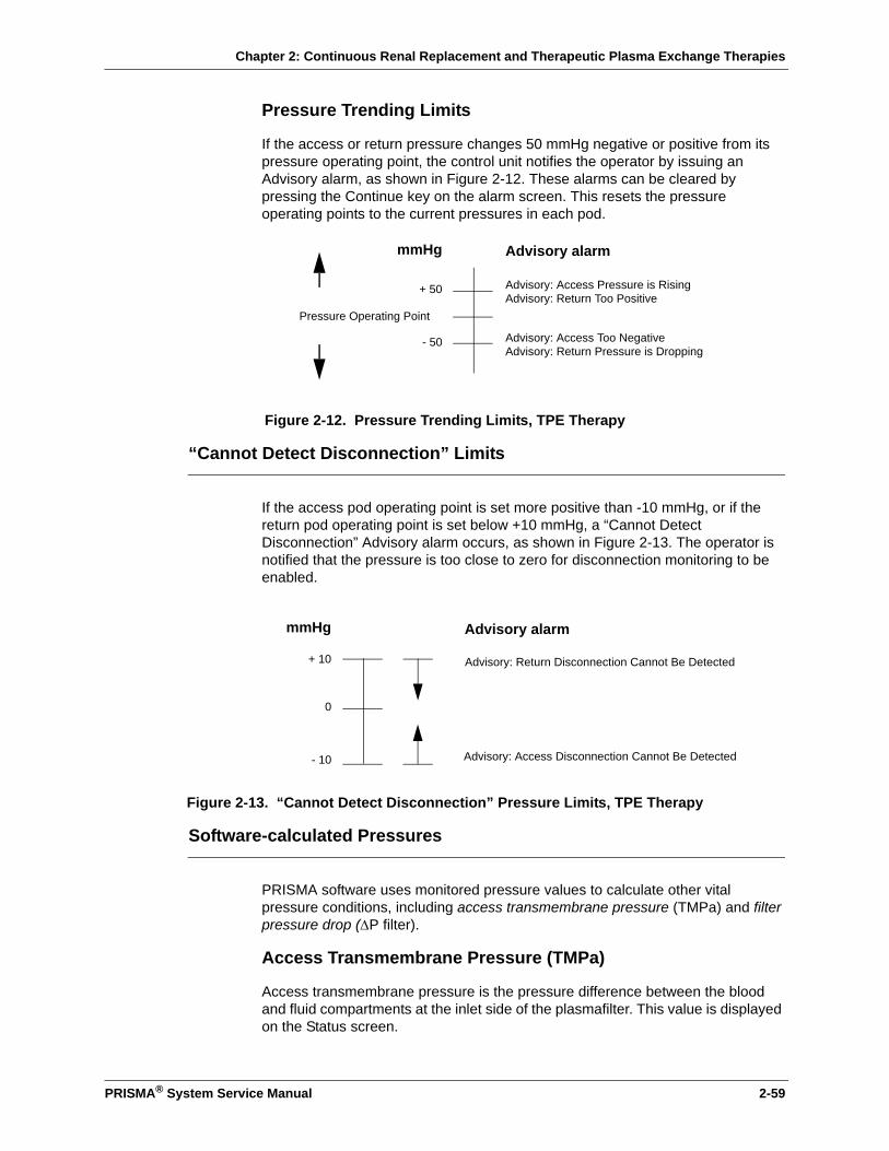
Chapter 2: Continuous Renal Replacement and Therapeutic Plasma Exchange Therapies
PRISMA® System Service Manual 2-59
Pressure Trending Limits
If the access or return pressure changes 50 mmHg negative or positive from its pressure operating point, the control unit notifies the operator by issuing an Advisory alarm, as shown in Figure 2-12. These alarms can be cleared by pressing the Continue key on the alarm screen. This resets the pressure operating points to the current pressures in each pod.
Figure 2-12. Pressure Trending Limits, TPE Therapy
“Cannot Detect Disconnection” Limits
If the access pod operating point is set more positive than -10 mmHg, or if the return pod operating point is set below +10 mmHg, a “Cannot Detect Disconnection” Advisory alarm occurs, as shown in Figure 2-13. The operator is notified that the pressure is too close to zero for disconnection monitoring to be enabled.
Figure 2-13. “Cannot Detect Disconnection” Pressure Limits, TPE Therapy
Software-calculated Pressures
PRISMA software uses monitored pressure values to calculate other vital pressure conditions, including access transmembrane pressure (TMPa) and filter pressure drop (∆P filter).
Access Transmembrane Pressure (TMPa)
Access transmembrane pressure is the pressure difference between the blood and fluid compartments at the inlet side of the plasmafilter. This value is displayed on the Status screen.
- 50
+ 50
Pressure Operating Point
Advisory alarm
Advisory: Access Pressure is Rising
Advisory: Access Too Negative
Advisory: Return Too Positive
Advisory: Return Pressure is Dropping
mmHg
- 10
+ 10
0
Advisory: Access Disconnection Cannot Be Detected
Advisory: Return Disconnection Cannot Be Detected
Advisory alarmmmHg
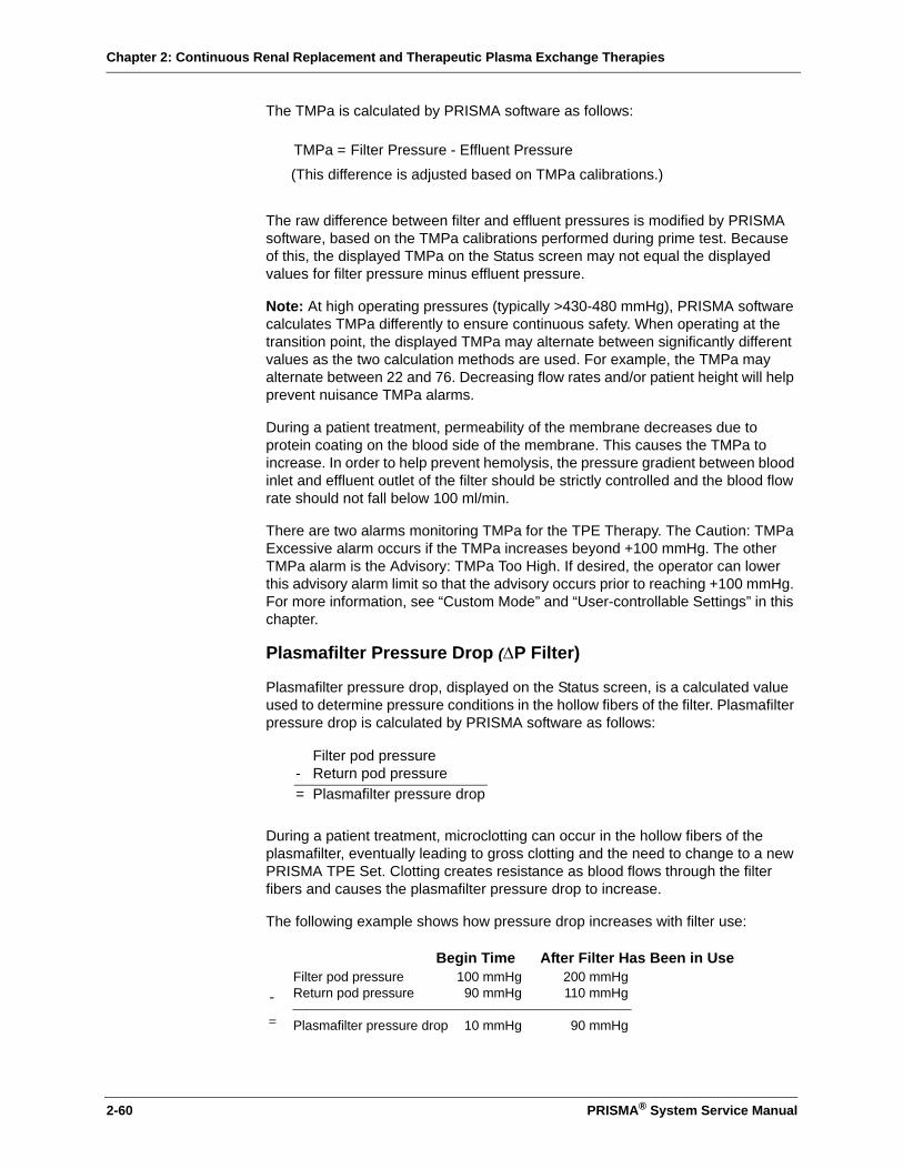
Chapter 2: Continuous Renal Replacement and Therapeutic Plasma Exchange Therapies
2-60 PRISMA® System Service Manual
The TMPa is calculated by PRISMA software as follows:
The raw difference between filter and effluent pressures is modified by PRISMA software, based on the TMPa calibrations performed during prime test. Because of this, the displayed TMPa on the Status screen may not equal the displayed values for filter pressure minus effluent pressure.
Note: At high operating pressures (typically >430-480 mmHg), PRISMA software calculates TMPa differently to ensure continuous safety. When operating at the transition point, the displayed TMPa may alternate between significantly different values as the two calculation methods are used. For example, the TMPa may alternate between 22 and 76. Decreasing flow rates and/or patient height will help prevent nuisance TMPa alarms.
During a patient treatment, permeability of the membrane decreases due to protein coating on the blood side of the membrane. This causes the TMPa to increase. In order to help prevent hemolysis, the pressure gradient between blood inlet and effluent outlet of the filter should be strictly controlled and the blood flow rate should not fall below 100 ml/min.
There are two alarms monitoring TMPa for the TPE Therapy. The Caution: TMPa Excessive alarm occurs if the TMPa increases beyond +100 mmHg. The other TMPa alarm is the Advisory: TMPa Too High. If desired, the operator can lower this advisory alarm limit so that the advisory occurs prior to reaching +100 mmHg. For more information, see “Custom Mode” and “User-controllable Settings” in this chapter.
Plasmafilter Pressure Drop (∆P Filter)
Plasmafilter pressure drop, displayed on the Status screen, is a calculated value used to determine pressure conditions in the hollow fibers of the filter. Plasmafilter pressure drop is calculated by PRISMA software as follows:
During a patient treatment, microclotting can occur in the hollow fibers of the plasmafilter, eventually leading to gross clotting and the need to change to a new PRISMA TPE Set. Clotting creates resistance as blood flows through the filter fibers and causes the plasmafilter pressure drop to increase.
The following example shows how pressure drop increases with filter use:
Filter Pressure - Effluent PressureTMPa =
(This difference is adjusted based on TMPa calibrations.)
Filter pod pressure- Return pod pressure= Plasmafilter pressure drop
Begin Time After Filter Has Been in Use
-
=
Filter pod pressure 100 mmHg 200 mmHgReturn pod pressure 90 mmHg 110 mmHg
Plasmafilter pressure drop 10 mmHg 90 mmHg
Chapter 2: Continuous Renal Replacement and Therapeutic Plasma Exchange Therapies
PRISMA® System Service Manual 2-61
In the above example, plasmafilter pressure drop increased by 80 mmHg.
During operation, software sets the initial value for plasmafilter pressure drop at the same time the initial operating points are established (shortly after entering Run mode). This initial value is reset each time the blood flow rate is changed. The amount of increase above the initial plasmafilter pressure drop contributes to the Advisory: Plasmafilter Is Clotting alarm. The operator can set the amount of increase that will trigger the alarm. For more information, see “Custom Mode” and “User-controllable Settings” in this chapter and “Filter Pressure—Plasmafilter Is Clotting Advisory Limits” in the Specifications chapter.

Chapter 2: Continuous Renal Replacement and Therapeutic Plasma Exchange Therapies
2-62 PRISMA® System Service Manual
This page is left intentionally blank

Chapter 3: Electronic Description
Chapter 3: Electronic Description
The PRISMA® Control Unit consists of seven major printed circuit card assemblies (CCAs), a power supply, display and touchscreen, pump motors, return line clamp, pressure sensors and a pressure diaphragm repositioning system (ARPS), weight scale assemblies, an air bubble detector (UABD), a blood leak detector and an anticoagulant syringe pump. The seven CCAs that provide a path for these functions are the Power Distribution CCA, Monitor CCA, Controller CCA, Detector CCA, Automatic Reposition CCA (ARPS), Driver CCA, and the Analog CCA.
For detailed electronic component information, see “Chapter 9: Schematics”.
Figure 3-1. PRISMA Block Diagram
LIGHTS
FAN
BLOOD PUMP &
TACH
TOUCHSCREEN DISPLAY
CONTROLLER CCA MONITOR CCA
ANALOG CCA
POWER FAIL
DRIVER CCA
DIALY. PUMP &
TACH
REPL. PUMP &
TACH
EFFL. PUMP &
TACH
SCALE CNTL. SCALE MON.
PRESS. XDUCERS
ARPS CCA
AIR PUMP
VALVE DRIVERS
ARPS PRESS.
XDUCER
RET. LINE CLAMP
SENSOR
DETECTOR CCA
UABD BLOOD LEAK
SPEAKER SER. COMM.
RET. LINE CLAMP
SYRINGE PUMP
SYRINGE PUMPE-O-T
LOADER
PRISMA® System Service Manual 3-1

Chapter 3: Electronic Description
Power System
Figure 3-2. PRISMA Power System Block Diagram
The PRISMA System contains a universal-input switching power supply which allows any standard ac line voltage (100 Vac, 115 Vac, 220 Vac, and 240 Vac at 50/60 Hz) to be directly connected without special wiring or hardware configurations. The power supply uses pulse-width modulation to control the amount of power provided from the primary side of the input transformer. Both ac voltage input lines are equipped with replaceable 5 amp fuses which are located in the power entry module, before the power switch.
The power supply provides regulated outputs of +24, +12, +5 and -5 Vdc, with test points (on the Power Distribution CCA) for measuring each voltage. A secondary fuse for the +5 Vdc is located on the Power Distribution CCA. Two separate lines supply ground references for the digital and +24 Vdc sources. Note that both grounds are connected together on the Power Distribution CCA.
Voltage Range Where Used
+24 Vdc ±0.96 Vdc Pump motors, return line clamp, display, status lights
+5.15 Vdc ±0.15 Vdc Digital logic, operational amplifiers
+12 Vdc,-5 Vdc
±0.48 Vdc Op amps, A/D converters, air bubble detector (UABD), scales, pressures, cooling fan (the fan uses +12 Vdc only)
+ 24 Vdc
+12 Vdc
+5 Vdc
-5 Vdc
GND (+24 VDC RETURN)
DIGITAL GND
POWERDISTRIBUTIONCCA
UNIVERSALPOWERSUPPLY
5AFUSES
ON/OFFSWITCH
HOT
NEUT
DRIVER CCA
5A
3-2 PRISMA® System Service Manual

Chapter 3: Electronic Description
Monitor CCA
Figure 3-3. Monitor CCA Block Diagram
The Monitor CCA contains:
• The display driver and audible alarm driver
• An RS-232 serial communication port
• A watch dog monitoring circuit
• A power-fail circuit
• The language EPROMs or flash devices
The Monitor CCA also:
• Monitors the status of most systems and CCAs
• Disables certain functions during alarm conditions
MONITORWATCH DOG
DRIVERCCA
See Page 3-20
DETECTOR CCA
See Page 3-12
AUTOMATICREPOSITION CCA
See Page 3-17
ANALOGCCA
See Page 3-25
CONTROLLERCCA
See Page 3-9
MONITORCCA
DISPLAYSPEAKER
COM2SERIALPORT
POWER FAIL VIA MAIN SWITCH
PRISMA® System Service Manual 3-3
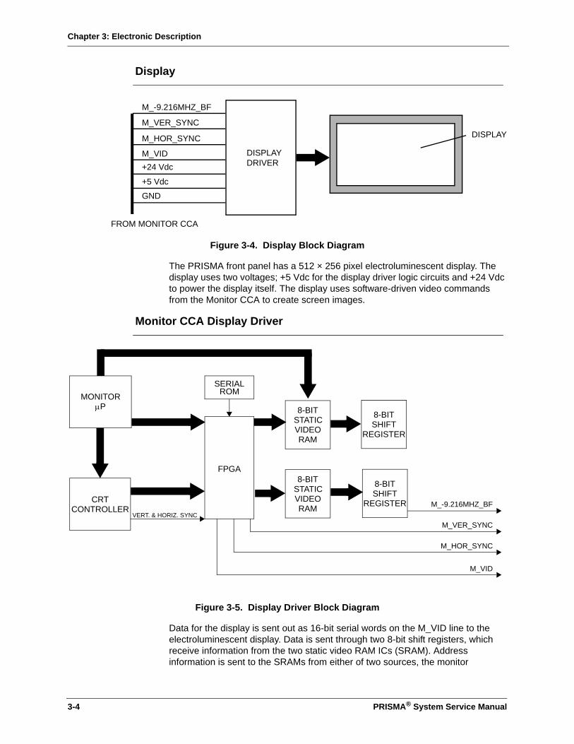
Chapter 3: Electronic Description
Display
Figure 3-4. Display Block Diagram
The PRISMA front panel has a 512 × 256 pixel electroluminescent display. The display uses two voltages; +5 Vdc for the display driver logic circuits and +24 Vdc to power the display itself. The display uses software-driven video commands from the Monitor CCA to create screen images.
Monitor CCA Display Driver
Figure 3-5. Display Driver Block Diagram
Data for the display is sent out as 16-bit serial words on the M_VID line to the electroluminescent display. Data is sent through two 8-bit shift registers, which receive information from the two static video RAM ICs (SRAM). Address information is sent to the SRAMs from either of two sources, the monitor
DISPLAYDRIVER
M_-9.216MHZ_BF
+24 Vdc
+5 Vdc
GND
DISPLAY
FROM MONITOR CCA
M_VER_SYNC
M_HOR_SYNC
M_VID
MONITORµP
SERIALROM
FPGA
CRTCONTROLLER
8-BITSTATICVIDEORAM
8-BITSTATICVIDEORAM
8-BITSHIFT
REGISTER
8-BITSHIFT
REGISTERVERT. & HORIZ. SYNC
M_VID
M_HOR_SYNC
M_VER_SYNC
M_-9.216MHZ_BF
3-4 PRISMA® System Service Manual
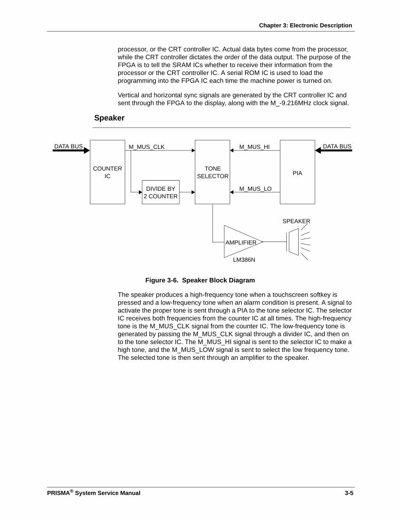
Chapter 3: Electronic Description
processor, or the CRT controller IC. Actual data bytes come from the processor, while the CRT controller dictates the order of the data output. The purpose of the FPGA is to tell the SRAM ICs whether to receive their information from the processor or the CRT controller IC. A serial ROM IC is used to load the programming into the FPGA IC each time the machine power is turned on.
Vertical and horizontal sync signals are generated by the CRT controller IC and sent through the FPGA to the display, along with the M_-9.216MHz clock signal.
Speaker
Figure 3-6. Speaker Block Diagram
The speaker produces a high-frequency tone when a touchscreen softkey is pressed and a low-frequency tone when an alarm condition is present. A signal to activate the proper tone is sent through a PIA to the tone selector IC. The selector IC receives both frequencies from the counter IC at all times. The high-frequency tone is the M_MUS_CLK signal from the counter IC. The low-frequency tone is generated by passing the M_MUS_CLK signal through a divider IC, and then on to the tone selector IC. The M_MUS_HI signal is sent to the selector IC to make a high tone, and the M_MUS_LOW signal is sent to select the low frequency tone. The selected tone is then sent through an amplifier to the speaker.
COUNTERIC
TONESELECTOR PIA
DIVIDE BY2 COUNTER
M_MUS_HI
M_MUS_LO
M_MUS_CLK DATA BUSDATA BUS
AMPLIFIER
LM386N
SPEAKER
PRISMA® System Service Manual 3-5
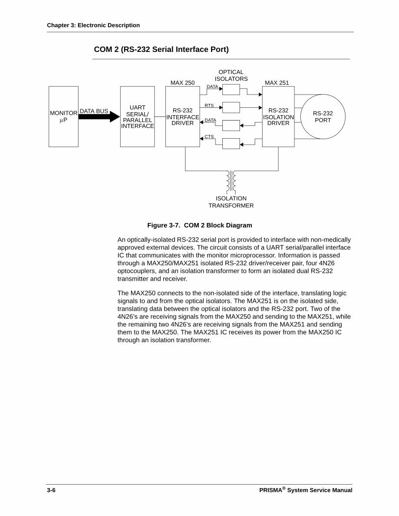
Chapter 3: Electronic Description
COM 2 (RS-232 Serial Interface Port)
Figure 3-7. COM 2 Block Diagram
An optically-isolated RS-232 serial port is provided to interface with non-medically approved external devices. The circuit consists of a UART serial/parallel interface IC that communicates with the monitor microprocessor. Information is passed through a MAX250/MAX251 isolated RS-232 driver/receiver pair, four 4N26 optocouplers, and an isolation transformer to form an isolated dual RS-232 transmitter and receiver.
The MAX250 connects to the non-isolated side of the interface, translating logic signals to and from the optical isolators. The MAX251 is on the isolated side, translating data between the optical isolators and the RS-232 port. Two of the 4N26’s are receiving signals from the MAX250 and sending to the MAX251, while the remaining two 4N26’s are receiving signals from the MAX251 and sending them to the MAX250. The MAX251 IC receives its power from the MAX250 IC through an isolation transformer.
MONITORµP
UARTSERIAL/
PARALLELINTERFACE
RS-232INTERFACE
DRIVERRS-232PORT
DATA
DATA
RTS
CTS
OPTICALISOLATORS
MAX 251MAX 250
DATA BUS
ISOLATIONTRANSFORMER
RS-232ISOLATION
DRIVER
3-6 PRISMA® System Service Manual
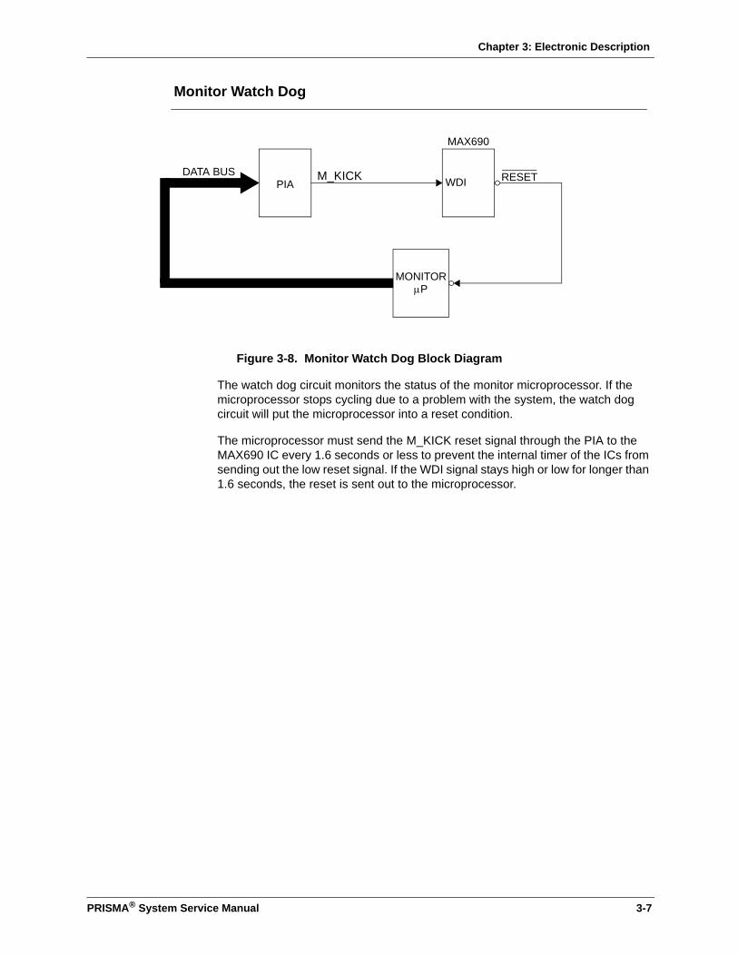
Chapter 3: Electronic Description
Monitor Watch Dog
Figure 3-8. Monitor Watch Dog Block Diagram
The watch dog circuit monitors the status of the monitor microprocessor. If the microprocessor stops cycling due to a problem with the system, the watch dog circuit will put the microprocessor into a reset condition.
The microprocessor must send the M_KICK reset signal through the PIA to the MAX690 IC every 1.6 seconds or less to prevent the internal timer of the ICs from sending out the low reset signal. If the WDI signal stays high or low for longer than 1.6 seconds, the reset is sent out to the microprocessor.
PIA
MONITORµP
MAX690
WDI RESETDATA BUS M_KICK
PRISMA® System Service Manual 3-7

Chapter 3: Electronic Description
Power Fail
Figure 3-9. Power Fail Block Diagram
The PRISMA System uses a microprocessor supervisory circuit IC to monitor the +5 Vdc. When the VCC supply drops too low, the MAX690 IC switches to the VBAT power, which is supplied by a charged super-capacitor. At the same time, the power supply sends a low voltage signal, M_-VCC_DROP, to a NAND gate. When the NAND gate receives a low signal, it will output a high signal to a second NAND gate. The second NAND gate will be receiving another high input from the MAX690 IC VOUT battery powered signal via the main power switch auxiliary contacts. With two high inputs, the second NAND gate output will go low, turning on the two transistors and providing a ground to the audible alarm on the Monitor CCA, thus producing an audible No Power Alarm warning tone which is powered from the super-capacitor.
To store data during a power interruption, the M_-VCC_DROP signal from the power supply also goes to the interrupt controller. This signal allows a minimum of 10 msec to store the data before the reset signal from the MAX 690 IC is received by the microprocessor. In addition to the warning tone, the MAX690 IC holds the microprocessor in a reset condition when the power is low.
When the circuit is operating normally, the MAX690 supervisory IC will be using VCC as the power source to VOUT. This signal goes through the power switch and returns to the second NAND gate as a high, but the output of this NAND gate will stay high because of the first NAND gate feeding it a low signal. This low signal will be maintained as long as the M_-VCC_DROP signal to the first NAND gate stays in a high, or safe, condition.
MAX690
POWER
VCC (+5 Vdc)VOUT
VBATAUDIBLE ALARM
3.3 F SUPERCAPACITOR
M_-VCC_DROP
M_PWR_SW_ONSWITCH
3-8 PRISMA® System Service Manual

Chapter 3: Electronic Description
Controller CCA
Figure 3-10. Controller CCA
The Controller CCA contains:
• Dual-ported RAM for communications with the Monitor microprocessor
• Softkey input circuitry
• A watch dog circuit for the controller microprocessor
The Controller CCA also:
• Sends the proper control signals to the Driver CCA to control the pumps, loader, syringe pump, and return line clamp
• Works with the Monitor CCA to maintain the system status
• Generates signals for the audible and visual alarms
• Uses feedback from the scales for pump speed control during the different therapies and flow rates
CONTROLLERCCADRIVER
CCASee Page 3-20
CONTROLLERWATCH DOG
MONITORCCA
See Page 3-3
TOUCHSCREEN
PRISMA® System Service Manual 3-9
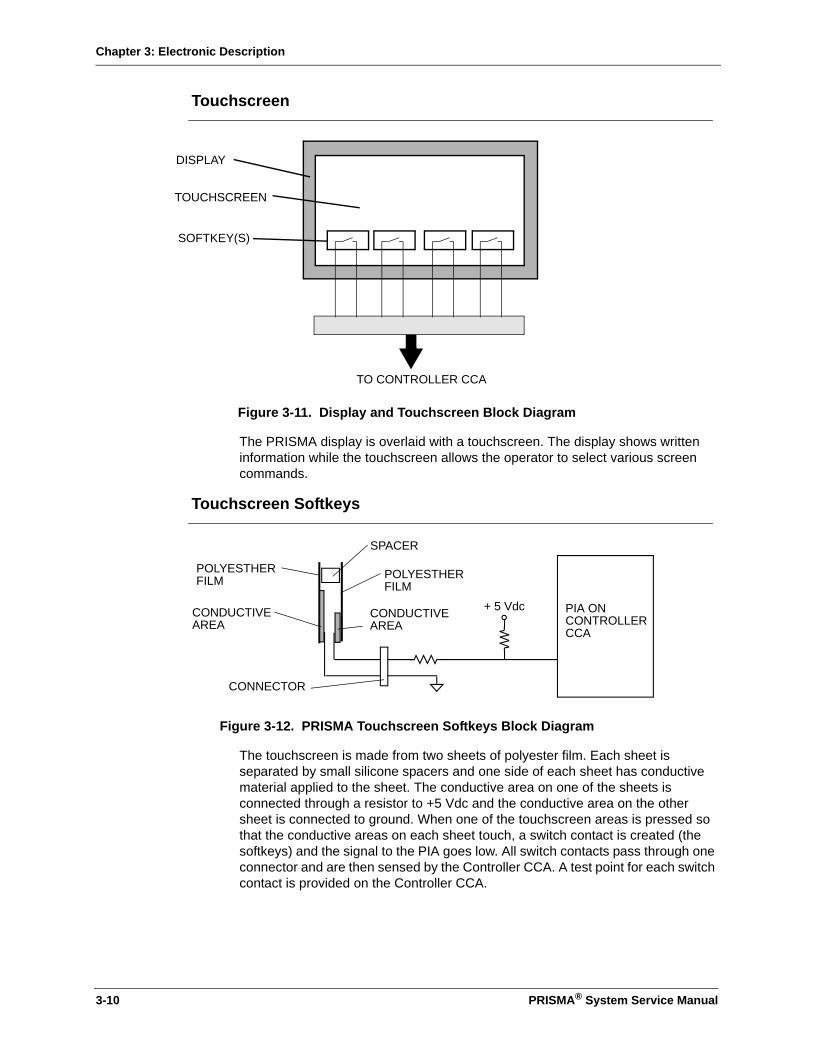
Chapter 3: Electronic Description
Touchscreen
Figure 3-11. Display and Touchscreen Block Diagram
The PRISMA display is overlaid with a touchscreen. The display shows written information while the touchscreen allows the operator to select various screen commands.
Touchscreen Softkeys
Figure 3-12. PRISMA Touchscreen Softkeys Block Diagram
The touchscreen is made from two sheets of polyester film. Each sheet is separated by small silicone spacers and one side of each sheet has conductive material applied to the sheet. The conductive area on one of the sheets is connected through a resistor to +5 Vdc and the conductive area on the other sheet is connected to ground. When one of the touchscreen areas is pressed so that the conductive areas on each sheet touch, a switch contact is created (the softkeys) and the signal to the PIA goes low. All switch contacts pass through one connector and are then sensed by the Controller CCA. A test point for each switch contact is provided on the Controller CCA.
TO CONTROLLER CCA
DISPLAY
TOUCHSCREEN
SOFTKEY(S)
+ 5 Vdc PIA ONCONTROLLERCCA
CONDUCTIVEAREA
CONDUCTIVEAREA
POLYESTHERFILM POLYESTHER
FILM
SPACER
CONNECTOR
3-10 PRISMA® System Service Manual
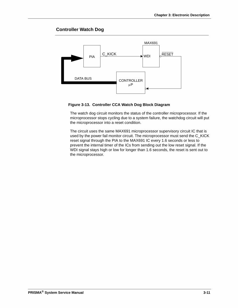
Chapter 3: Electronic Description
Controller Watch Dog
Figure 3-13. Controller CCA Watch Dog Block Diagram
The watch dog circuit monitors the status of the controller microprocessor. If the microprocessor stops cycling due to a system failure, the watchdog circuit will put the microprocessor into a reset condition.
The circuit uses the same MAX691 microprocessor supervisory circuit IC that is used by the power fail monitor circuit. The microprocessor must send the C_KICK reset signal through the PIA to the MAX691 IC every 1.6 seconds or less to prevent the internal timer of the ICs from sending out the low reset signal. If the WDI signal stays high or low for longer than 1.6 seconds, the reset is sent out to the microprocessor.
PIA
CONTROLLERµP
MAX691
WDI RESET
DATA BUS
C_KICK
PRISMA® System Service Manual 3-11

Chapter 3: Electronic Description
Detector CCA
Figure 3-14. Detector CCA Block Diagram
The Detector CCA contains circuitry for:
• The ultrasonic air bubble detector
• The blood leak detector
ULTRASONIC AIR BUBBLE DETECTOR
BLOOD LEAKDETECTOR
DATA BUS
RCVR XDUCER
M_uBUB_TST
C_uBUB_TST
XMTR_XDUCER
M_-mBUBBLE
M_-uBUBBLE
C_-AIR
C_uBUBBLE
BLD_RCVR
M_-RES2
M_-WR3
M_BLD_TEST
M_-BLD_CS
M_-RD3
M_CK1MHZ
M_CK1.95MHZ
M_PUL2_FLG
BLD_XMTR
M_BLD_INT
M_-UABD_TROUB
3-12 PRISMA® System Service Manual
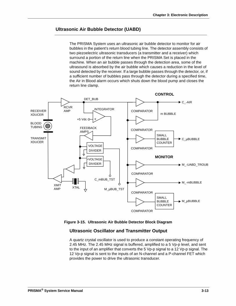
Chapter 3: Electronic Description
Ultrasonic Air Bubble Detector (UABD)
The PRISMA System uses an ultrasonic air bubble detector to monitor for air bubbles in the patient’s return blood tubing line. The detector assembly consists of two piezoelectric ultrasonic transducers (a transmitter and a receiver) which surround a portion of the return line when the PRISMA Set is placed in the machine. When an air bubble passes through the detection area, some of the ultrasound is absorbed by the air bubble which causes a reduction in the level of sound detected by the receiver. If a large bubble passes through the detector, or, if a sufficient number of bubbles pass through the detector during a specified time, the Air in Blood alarm occurs which shuts down the blood pump and closes the return line clamp.
Figure 3-15. Ultrasonic Air Bubble Detector Block Diagram
Ultrasonic Oscillator and Transmitter Output
A quartz crystal oscillator is used to produce a constant operating frequency of 2.45 MHz. The 2.45 MHz signal is buffered, amplified to a 5 Vp-p level, and sent to the input of an amplifier that converts the 5 Vp-p signal to a 12 Vp-p signal. The 12 Vp-p signal is sent to the inputs of an N-channel and a P-channel FET which provides the power to drive the ultrasonic transducer.
XTALXMITAMP
RCVRAMP
FEEDBACKAMPS
C_-AIR
SMALLBUBBLECOUNTER
m BUBBLE
C_µBUBBLETRANSMITXDUCER
RECEIVERXDUCER
COMPARATOR
COMPARATOR
COMPARATOR
BLOODTUBING
INTEGRATOR
CONTROL
M_-UABD_TROUB
M_-mBUBBLE
M_µBUBBLE
COMPARATOR
COMPARATOR
COMPARATOR
MONITOR
VOLTAGEDIVIDER
VOLTAGEDIVIDER
SMALLBUBBLECOUNTER
M_µBUB_TST
C_mBUB_TST
DET_BUB
++5 Vdc
PRISMA® System Service Manual 3-13

Chapter 3: Electronic Description
Ultrasonic Receiver Output
The signal from the receiver transducer is small and must be amplified to a level of about 3.5 V p-p by the receiver amplifier. The 3.5 V p-p signal is then demodulated, converted into a dc voltage and then filtered. After the bubble detection signal has been filtered, it is fed to several voltage comparators.
Automatic level control is used to maintain a constant average ultrasonic signal level by providing feedback to the transducer drive circuitry. The output from the receiver amplifier is fed to the inverting input of an integrator. The 2.5 Vdc input to the non-inverting input of the amplifier is from the +5 Vdc reference. If the signal from the receiver transducer is less than the reference voltage, the output of the integrator increases. If the receiver signal voltage is greater than the reference voltage, the integrator output decreases. The output of the integrator is then amplified and fed back to the transducer drive circuit which controls the transducer drive output.
Under normal circumstances (no bubbles present), the comparators all receive the same 2.5 Vdc signal. However, when a bubble passes through the detector, the voltage drops below 2.5 Vdc. Bubbles with a diameter of about 0.58 mm cause the voltage to drop to about 2.2 Vdc for a designated time period and create a Micro Air in Blood alarm. Bubbles larger than 3 mm cause the voltage to drop below 1.5 Vdc and create an Air in Blood alarm.
Note: The voltage at the comparators is approximately 0.0 Vdc when there is no tubing installed in the detector.
To ensure safety, two separate but identical comparator sections are used. One section sends signals to the Monitor microprocessor and the other sends signals to the controller microprocessor. Should a component failure occur in one (monitor or controller) section, the other (monitor or control) section will still operate properly. However since both sections operate in an identical manner, any disagreement between the two sections is detected by both microprocessors and an Air in Blood alarm would occur.
The output of the comparators will change state to 0 or +5 Vdc whenever a large bubble is detected. Small bubble detection and monitoring however, are treated differently. When a small bubble is detected, the microbubble comparator output goes high, allowing the output of the JK flip flop to oscillate at the clock frequency. This stream of pulses is counted, monitored and compared to the blood pump speed. When the stream of pulses exceeds a limit that is defined by the PRISMA software, the Micro Air in Blood alarm is activated.
3-14 PRISMA® System Service Manual

Chapter 3: Electronic Description
Blood Leak Detector (BLD)
Figure 3-16. Blood Leak Detector Assembly
The non-invasive PRISMA blood leak detector (BLD) monitors the effluent line for blood passing through the filter. Unlike chronic dialysis machines where the effluent goes down the drain, the PRISMA System collects the effluent in the effluent bag. Low concentrations of blood in the effluent bag may cause the contents of the bag to appear red or pink, even though the leak may not be enough to activate the alarm.
The BLD consists of a detector housing, an infrared LED, a phototransistor and two mirrors. The LED and phototransistor are held in the housing at an angle such that the light beam passes through the tubing four times before being detected by the phototransistor.
Figure 3-17. Blood Leak Detector Block Diagram
Operation
The Detector CCA drive circuitry for the blood leak detector pulses the infrared LED approximately every 200 msec, and the output is sent to the A/D converter
MIRRORLIGHT BEAM
INFRARED LED PHOTOTRANSISTOR
EFFLUENT LINE
MIRROR
BLD_XMTR
GND
BLD_RCVR
MONITOR CCA
A/DCONVERTER
DATA BUS
+5 Vdc
START_ALE
AD_OE
M_-BLD_TEST
M_BLD_EN
PLD
IRLED
DETECTOR CCA
D/ACONVERTER
BLOOD LEAK DET. HOUSING
PRISMA® System Service Manual 3-15
Chapter 3: Electronic Description
on the Detector CCA. From this A/D converter, the signal is sent to the Monitor CCA through the data bus. When you enter the Service-Blood Leak Detector Diagnose screen the data displays the Difference value (the difference between the driver and receiver signal) or the Average value (the Difference value for a 15 – 20 second time period). For more information about the data displayed on the Service-Diagnose Blood Leak Detector screen, see “Service-Blood Leak Detector Diagnose Screen” on page 5-19.
When the saline-filled line is installed in the detector, the output of the A/D converter also creates a basis from which two distinct alarm conditions can be detected.
• When the received A/D signal is 81 or lower, this indicates that blood is in the line due to a minimum blood leak (as specified in the operator’s manual), or that there is air in the line.
• When the received A/D signal is 229 or greater, this indicates that the tubing is not installed in the detector housing.
To ensure that air bubbles do not cause any nuisance alarms, the Average value is used to generate a Blood Leak alarm.
Note: The Average value must remain at an alarm level (less than or equal to 81) for 22 seconds or more to generate the Blood Leak alarm.
Normalization
The blood leak detector is automatically normalized by the PRISMA System near the end of the priming sequence when the effluent line is full of priming solution. The infrared LED drive signal is adjusted so the received A/D signal range is 167 to 184. From this A/D range, the control unit can detect when blood is present or when the tubing is not installed. For more information about the normalization procedure, see “Service-Blood Leak Detector Diagnose Screen” on page 5-19.
3-16 PRISMA® System Service Manual

Chapter 3: Electronic Description
Automatic Reposition System (ARPS)
The automatic repositioning system (ARPS) is used to ensure proper pressure monitoring. During each Periodic Self-Test and Prime Self-Test, the pressure pod diaphragms in the blood circuit are automatically repositioned using the ARPS system.
The ARPS system contains the following ARPS components:
• The ARPS CCA, with air pump motor drivers, A/D converter, PAL decoders, and valve drivers
• The air pump motor
• The ARPS pressure sensor
• Four internal valves
Note: There are no alarms generated that specify a failure in the ARPS. If a failure occurs, it will be detected during one of the Self-Tests and a Self-Test Malfunction alarm will occur. For more information, see “Failure of the Periodic Self-test” on page 4-3.
Reposition Sequence
Figure 3-18. ARPS Functional Block Diagram
The ARPS system sequentially repositions each diaphragm in the following order: effluent, return, filter, access. The ARPS air pump pressurizes the tubing on the air pump-side of each valve until the pressure is equal on both sides of the valve. For example, if the pressure at the return valve is 200 mmHg, the air pump pressurizes the other side of the return valve to 200 mmHg. Once pressurized, the
ARPSPRESSURETRANSDUCER
ARPSAIRPUMP
EFFLUENTVALVE
FILTERVALVE
ACCESSVALVE
RETURNVALVE
ACCESSPRESSURETRANSDUCER
FILTERPRESSURETRANSDUCER
RETURNPRESSURETRANSDUCER
EFFLUENTPRESSURETRANSDUCER
OPEN TO AIR
TUBING
PRISMA® System Service Manual 3-17
Chapter 3: Electronic Description
valve opens and the air pump then injects additional air until the pressure at the sensor rises by 50 mmHg and remains above that level for 2 seconds, indicating the end of the pressure diaphragm travel. When the end of the diaphragm travel is determined, the air pump removes approximately 1 cc of air and at that point, the diaphragm will be in its neutral position. The system then automatically performs a pressure verification to ensure that the post-reposition pressure is within ±50 mmHg of the pre-reposition pressure. If the pressure is outside of this range a Malfunction: Self-Test Failure alarm is generated. The sequence is different for pressure pods that normally read negative pressure than for the pods that normally read positive pressures. The two sequences are described below.
Note: Only one pressure pod is tested at a time. When one of the pods has been repositioned, the system test proceeds to the next pressure pod. This cycle continues until all pods have been repositioned.
Effluent (TPE Only), Filter, Return Pressure Pods
The filter and return pressure pods in all therapies, and the effluent pressure pod in TPE therapy, normally operate under positive pressure. During the repositioning sequence, each valve is opened and the air pump injects air behind the diaphragm until it is pressed against the top of the pressure pod. The pressure is maintained for approximately 2 seconds, then approximately 1 cc of air is removed and the diaphragm is considered to be in a neutral position.
Effluent (CRRT Only), Access Pressure Pods
The access pressure pod, in all therapies, and effluent pressure pod, in TPE therapy, normally operate under negative pressures. During the repositioning sequence, each valve is then opened and the air pump removes air behind the diaphragm until it is pressed against the bottom of the pressure pod. The pressure is maintained for approximately 2 seconds, then approximately 1 cc of air is injected and the diaphragm is considered to be in a neutral position.
3-18 PRISMA® System Service Manual
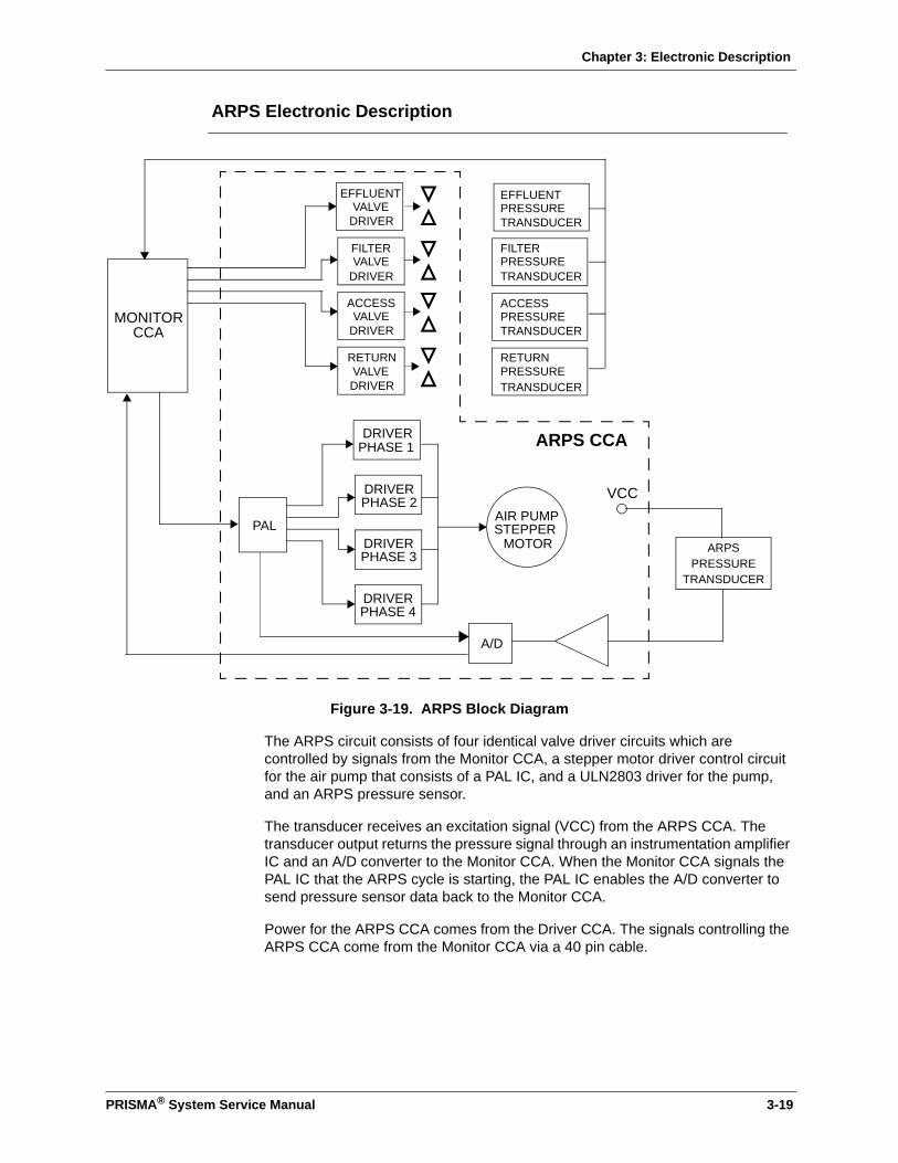
Chapter 3: Electronic Description
ARPS Electronic Description
Figure 3-19. ARPS Block Diagram
The ARPS circuit consists of four identical valve driver circuits which are controlled by signals from the Monitor CCA, a stepper motor driver control circuit for the air pump that consists of a PAL IC, and a ULN2803 driver for the pump, and an ARPS pressure sensor.
The transducer receives an excitation signal (VCC) from the ARPS CCA. The transducer output returns the pressure signal through an instrumentation amplifier IC and an A/D converter to the Monitor CCA. When the Monitor CCA signals the PAL IC that the ARPS cycle is starting, the PAL IC enables the A/D converter to send pressure sensor data back to the Monitor CCA.
Power for the ARPS CCA comes from the Driver CCA. The signals controlling the ARPS CCA come from the Monitor CCA via a 40 pin cable.
MONITORCCA
RETURNVALVEDRIVER
EFFLUENTVALVE
DRIVER
FILTERVALVE
DRIVER
ACCESSVALVE
DRIVER
RETURNPRESSURE
EFFLUENTPRESSURETRANSDUCER
FILTERPRESSURETRANSDUCER
ACCESSPRESSURETRANSDUCER
TRANSDUCER
DRIVERPHASE 1
DRIVERPHASE 2
DRIVERPHASE 3
DRIVERPHASE 4
AIR PUMPSTEPPER
MOTORPAL
A/D
ARPSPRESSURE
TRANSDUCER
ARPS CCA
VCC
PRISMA® System Service Manual 3-19

Chapter 3: Electronic Description
Driver CCA
Figure 3-20. Driver CCA Block Diagram
BLOODPUMP
DRIVER
PHASE1_HIPHASE1_LOPHASE2_HIPHASE1_LO
REPLACEMENT
STEPPERMOTOR
DIALYSATE
STEPPERMOTOR
EFFLUENT
STEPPERMOTOR
BLOOD
STEPPERMOTOR
TACH
TACH
TACH
TACH
C_BP_CLKC_BP_A12
SYRINGEPUMP
STEPPERMOTOR
LOADERSTEPPERMOTOR
RETURNCLAMP
CLAMPDRIVER
24V ENABLESAFETY
SWITCHES
SYRINGEDRIVER
SW_24Vn SWITCHED_24VSW_24V
CLAMP_COMMANDSOLENOIDRTN
M_24SWC_24SW
C_HEP_STEPC_HEP_ENM_HEP_SENSE
C_LOAD_STEPC_LOAD_ENC_LOAD_DIR
C_CK2_5KHZC_CLAMP_OPEN
PLD
C_GLAMP
QUADAND GATE
POWERDRIVER
C_YLAMP
C_RLAMP
VCC
YELLOW
RED
+24V
+12V
FAN
GREEN
STATUSLAMP
C_BP_A13C_BP_A14
REPLACEMENT
PUMP
DRIVER
C_REP_CLKC_REP_A12C_REP_A13C_REP_A14
C_WST_CLKC_WST_A12C_WST_A13C_WST_A14
DIALYSATE
PUMP
DRIVER
C_DIA_CLKC_DIA_A12C_DIA_A13C_DIA_A14
EFFLUENT
PUMP
DRIVER
PHASE1_HIPHASE1_LOPHASE2_HIPHASE1_LO
PHASE1_HIPHASE1_LOPHASE2_HIPHASE1_LO
PHASE1_HIPHASE1_LOPHASE2_HIPHASE1_LO
HEP_PH1_HIHEP_PH1_LOHEP_PH2_HIHEP_PH2_LO
LOADERDRIVER
LOAD_PH1_HILOAD_PH1_LOLOAD_PH2_HILOAD_PH2_LO
PUMP
PUMP
PUMP
PUMP
3-20 PRISMA® System Service Manual

Chapter 3: Electronic Description
The Driver CCA contains circuits for the:
• Pumps
• Return line clamp
• Syringe pump
• Cartridge loader
• Lights and fan
Peristaltic Pumps
The four peristaltic pumps in the PRISMA System are driven by step-type dc motors that are capable of continuous operation between 0 and 220 rpm.
Pump Circuits
Figure 3-21. Peristaltic Pump Block Diagram
The PRISMA System uses microstepping motor driver circuitry to drive the pump motors. Microstepping requires that the current supplied to the motor must be carefully controlled. The current is controlled by dividing each full step of the motor (normally 200 steps per revolution, or 1.8 degrees per step) into a set of microsteps. Each microstep then corresponds to a limiting current level which is then applied to the motor.
The motor speed is determined by the square wave CLK signal frequency which is generated by the Controller CCA, which is sent to the motor through the Driver CCA. The greater the frequency of the CLK signal, the greater the pump motor rpm. The motor driver circuits are enabled by the C_24 SW2 and M_24 SW2
EN_P_PUMPS
CLK
A12 - A14
ADDR 0 ADDR 07
D/ACONVERT.D0 - D6
RFB AOUT A
DRIVER
DRIVERH-BRIDGEDFET
ELT.LOOK-UPTABLES
DIRECTIONDECODER
RST
DECODE &DEMULITPLEX
H-BRIDGEDFET +24 Vdc
PUMPMOTOR
CURRENT SENSESCHMIDTTRIGGER AND
TACH FB
RFB BOUT B
TO MONITORCCA
LATCH
CURRENT SENSE
CAPACITOR
PRISMA® System Service Manual 3-21

Chapter 3: Electronic Description
signals. If either signal is low, none of the motors will operate (including the syringe pump and line clamp).
Motor direction is encoded from the status of the A12, A13, and A14 inputs to the EPROM (27C256) look-up tables. If A12 and A13 are low and A14 is high, the motor operates in the reverse direction (clockwise). If all three inputs are high, no power is applied to the motor. All other combinations of A12, A13, and A14 will cause the motor to run counterclockwise.
Each motor contains two windings and each winding must be alternately energized to drive the pump motor. The motor is driven by applying sinusoidal currents to each set of windings. The sinusoidal current for one winding is 90° out of phase with the other winding.
As the CLK signal frequency increases, the D/A converter output increases. The D/A converter output is sent to the comparator input which creates a pulse width modulated output and drives the H-bridged FET rectifier.The latch allows the +24 Vdc to bleed off through the H-bridge so that the motors are free to turn when the power is off.
A Hall effect sensor mounted on the pump generates one pulse for each revolution of the pump. The signal passes through a ribbon cable to the Driver CCA where it is conditioned with a Schmidt trigger and capacitor. The conditioned Hall effect signal is then sent to the Monitor CCA through a 50-pin ribbon cable.
Return Line Clamp
Figure 3-22. Return Line Clamp Block Diagram
The return line clamp is used to isolate the patient from the PRISMA Set in the event of certain alarm conditions. The line clamping piston is spring-loaded so that it is normally closed and the line clamp solenoid must be energized for the clamping piston to be in the open position. The clamp solenoid is controlled by cycling the input to the FET.
The PLD IC receives the C_CLAMP_OPEN signal from the control processor along with the C_CLK125K signal and produces an output pulse train consisting of a 0.1 msec pulse followed by a continuous 1/8 duty cycle square wave. This pulse train is then sent through a 5-to-12 Vdc converter and is then applied to the input of the FET. The 0.1 msec pulse switches the FET between 24 Vdc and ground to produce a clamp solenoid current of about 2.5 A which is sufficient to open the clamp. The current then drops to about 310 mA to hold the clamp open.
C_ CLAMP_OPEN
5 Vdc TO12 VdcCONVERTERC_CLK125K
FET
+12Vdc+24 Vdc 0.75 A FUSE
(THERMAL)
3 OHM2.5 W
CLAMPSOLENOID
PLD CLAMP_COMMAND
3-22 PRISMA® System Service Manual
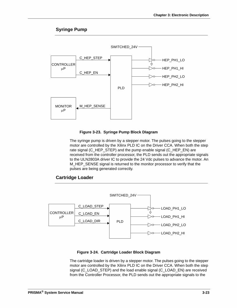
Chapter 3: Electronic Description
Syringe Pump
Figure 3-23. Syringe Pump Block DIagram
The syringe pump is driven by a stepper motor. The pulses going to the stepper motor are controlled by the Xilinx PLD IC on the Driver CCA. When both the step rate signal (C_HEP_STEP) and the pump enable signal (C_HEP_EN) are received from the controller processor, the PLD sends out the appropriate signals to the ULN2803A driver IC to provide the 24 Vdc pulses to advance the motor. An M_HEP_SENSE signal is returned to the monitor processor to verify that the pulses are being generated correctly.
Cartridge Loader
Figure 3-24. Cartridge Loader Block Diagram
The cartridge loader is driven by a stepper motor. The pulses going to the stepper motor are controlled by the Xilinx PLD IC on the Driver CCA. When both the step signal (C_LOAD_STEP) and the load enable signal (C_LOAD_EN) are received from the Controller Processor, the PLD sends out the appropriate signals to the
CONTROLLERµP
MONITORµP
PLD
C_HEP_STEP
M_HEP_SENSE
C_HEP_EN
HEP_PH1_LO
HEP_PH1_HI
HEP_PH2_LO
HEP_PH2_HI
SWITCHED_24V
CONTROLLERµP
PLD
C_LOAD_STEP
C_LOAD_DIR
LOAD_PH1_LO
LOAD_PH1_HI
LOAD_PH2_LO
LOAD_PH2_HI
SWITCHED_24V
C_LOAD_EN
PRISMA® System Service Manual 3-23
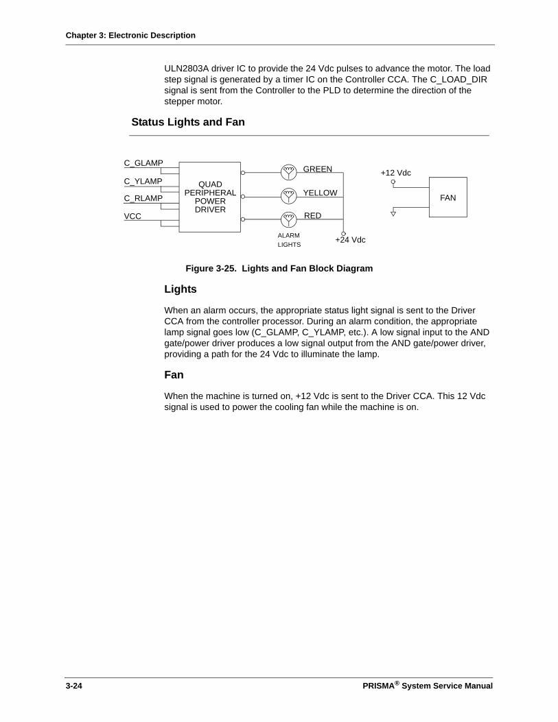
Chapter 3: Electronic Description
ULN2803A driver IC to provide the 24 Vdc pulses to advance the motor. The load step signal is generated by a timer IC on the Controller CCA. The C_LOAD_DIR signal is sent from the Controller to the PLD to determine the direction of the stepper motor.
Status Lights and Fan
Figure 3-25. Lights and Fan Block Diagram
Lights
When an alarm occurs, the appropriate status light signal is sent to the Driver CCA from the controller processor. During an alarm condition, the appropriate lamp signal goes low (C_GLAMP, C_YLAMP, etc.). A low signal input to the AND gate/power driver produces a low signal output from the AND gate/power driver, providing a path for the 24 Vdc to illuminate the lamp.
Fan
When the machine is turned on, +12 Vdc is sent to the Driver CCA. This 12 Vdc signal is used to power the cooling fan while the machine is on.
C_GLAMP
C_YLAMP
C_RLAMP
VCC
YELLOW
RED
+24 Vdc
+12 Vdc
FAN
GREEN
ALARMLIGHTS
QUADPERIPHERAL
POWERDRIVER
3-24 PRISMA® System Service Manual

Chapter 3: Electronic Description
Analog CCA
Figure 3-26. Analog CCA Block Diagram
The Analog CCA contains circuitry for:
• Pressure monitoring
• Scales (Weight Transducers) to weigh dialysate, replacement solution/fluid, and effluent bags or containers
• Biasing circuitry for the return line clamp position sensor
PRESS.XDUCER& AMPS
PRESS.XDUCER& AMPS
PRESS.XDUCER& AMPSCARP
CARP1
CARP2
PRESS.XDUCER& AMPS ANALOG
SWITCHES
ANALOGSWITCHES
C_CK1.95KHZ
A/DCONVERTERPRESSURES
MAØ
M_CK1MHZ
MPTDCRSn
A/DCONVERTER
SCALE(MONITOR)
WEIGHT TRANSDUCER
& AMPS
A/DCONVERTER
SCALE(CONTROL)
MLVDTCSn
CLVDTCSn
C_AØ
MAØ
M_2XD
M_PTDCR_INT
M_LVDT_INT
C_LVDT_INT
C_XD
WEIGHT TRANSDUCER
& AMPS
C_CK1.95KHZ
C_CK1.95KHZ
C_CK1.95KHZ
C_CK1.95KHZ
M_CLAMP_CLOSED
RETURN LINE CLAMP POSITION SENSOR
(Located on Return Line Clamp) Page 3-29
ANALOGSWITCHES
ANALOGSWITCHES
M_2XD
PRISMA® System Service Manual 3-25

Chapter 3: Electronic Description
Pressure Sensors
Figure 3-27. Pressure Sensor Block Diagram
The PRISMA System uses pressure sensors to monitor:
• Filter pressure (–50 to +500 mmHg)
• Access pressure (+50 to –250 mmHg)
• Return pressure (–50 to +350 mmHg)
• Effluent pressure (–350 to +50 mmHg, in CRRT therapies, –50 to +350 mmHg in TPE therapy)
• Reposition pressure: (–250 to +250 mmHg)
Note: The reposition pressure sensor circuitry is in the ARPS CCA.
The Analog CCA uses four identical circuits to drive and condition the four separate pressure sensor signals. The pressure sensor transducer is a semiconductor strain gauge bridge that responds to pressure changes. As the pressure applied to the pressure sensor changes, the bridge becomes unbalanced and produces a voltage difference between the output terminals.
A 1.95 KHz oscillator signal, which originates on the Controller CCA, is used to drive the pressure sensor’s bridge. The driver circuits convert the +5 Vdc square wave into a 10 Vp-p signal which is applied to each side of the bridge. CARP 1 is the 1.95 KHz signal for the return and effluent pressure sensor, and CARP 2 is the 1.95 KHz signal for the filter and access pressure sensor. The transducer output signal passed is through a pair of unity gain amplifiers, and then sent to a differential amplifier. The difference is then amplified and sent to the multiplexer where the signals are clocked through to the A/D and sent to the Monitor CCA.
CARP1 ORCARP2
DRIVERCIRCUITS
CDX IIITRANSDUCER*
UNITY GAIN AMPLIFIERS
DIFFERENTIALAND GAINAMPLIFIER
C_CLK1.95KHZ
TIMINGCIRCUITS
MULTI- A/DCONVERTER
LATCHES
PDET 1, 2, 3, 4
TO MONITORCCA
10 Vp-p
* CDX III IS MOUNTED ON THE FRONT PANEL
PLEXER
3-26 PRISMA® System Service Manual

Chapter 3: Electronic Description
Scale Assemblies (Weight Transducer)
LVDT Scale
Figure 3-28. Scale Assembly Block Diagram
Each of the PRISMA scale assemblies consists of six linear springs and two LVDT (linear variable displacement transformer) sensors to convert weight into an electrical signal. In each scale assembly, one LVDT provides input for the control functions and another LVDT provides input for the monitor functions. Scales are necessary to measure:
• Dialysate solution
• Replacement solutions
• Effluent fluids
The LVDTs have a primary winding and two secondary windings. The secondary windings are in series and are symmetrically located on each side of the primary winding. When the LVDT core is located in the center of the primary and secondary windings, the output voltage developed by the secondary windings is equal (0 Vdc). When the LVDT core moves away from the center of the coils, an increasing voltage develops. The voltage developed is proportional to the core displacement.
A single analog switch is used to produce a +5 square wave (1.95 KHz) which is passed through a separate amplifier for each LVDT primary winding. When the core is at the top of its travel range, the output of the secondary winding amplifier is -3 Vdc. When the core is pulled down to its maximum travel range (representing 6 Kg in weight), the output of the secondary winding amplifier is +3 Vdc.
ANALOGSWITCH
DRIVERCIRCUIT SWITCHES
TIMINGCIRCUITS
C_CK1.95KHZ
A/DCONVERTER
TO MONITORCCA
LVDT*
PRIMARYWINDING
CORE
SECONDARYWINDING
* LVDTs ARE MOUNTED IN THE SCALE ASSEMBLIES
& ANALOGMULTIPLEXER
PRISMA® System Service Manual 3-27

Chapter 3: Electronic Description
Load Cell Scale
Figure 3-29. Load Cell Scale Assembly Block Diagram
Each load cell is made up of a bar of alluminium specially produced to hold the strain gage bridge which represents the sensitive element of the load cell.
The output signal of the bridge is zero when there is no weight applied and it increases in direct proportion to the weight applied.
Before being sent to the A/D convertor on the ANALOG board, the output of the cell is amplified and sinchronized to the command signal X_CK1.95KHZ.
Typical output values of the amplifier, measured on the TPAOC and TPAOM of the scale board, are shown below:
Weight (Kg) Output Signal (mVdc)
0 335 / 376
4 -38 / -125
6 -185 / -364
A/D
ANALOG
MONITOR
C_CK1.95KHZ
TO
-
+
AMPLIFIER
CCA
CIRCUIT
CONVERTER
TIMING
MULTIPLEXER&SWITCH
ANALOG
BRIDGE
CIRCUIT
SWITCH
DRIVER
SWITCH
VCC
ANALOG
3-28 PRISMA® System Service Manual
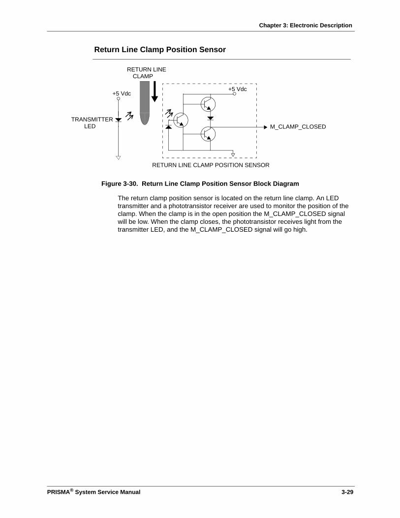
Chapter 3: Electronic Description
Return Line Clamp Position Sensor
Figure 3-30. Return Line Clamp Position Sensor Block Diagram
The return clamp position sensor is located on the return line clamp. An LED transmitter and a phototransistor receiver are used to monitor the position of the clamp. When the clamp is in the open position the M_CLAMP_CLOSED signal will be low. When the clamp closes, the phototransistor receives light from the transmitter LED, and the M_CLAMP_CLOSED signal will go high.
+5 Vdc
M_CLAMP_CLOSED
+5 Vdc
RETURN LINECLAMP
RETURN LINE CLAMP POSITION SENSOR
TRANSMITTERLED
PRISMA® System Service Manual 3-29

Chapter 3: Electronic Description
This page is left intentionally blank
3-30 PRISMA® System Service Manual

Chapter 4: Software Description
Chapter 4: Software Description
The PRISMA software routines described here are: Power Up, Periodic Self-test, Prime, Prime Test, Fluid Balance Calculations, Alarms, and Service Mode operation.
Power Up
To ensure that the basic functions of the microprocessors and memory are operating properly, the PRISMA Control Unit performs the following self-checks when the power is turned on.
• Processor Flag Check. The processor verifies that all condition flags can be set. If this test fails, the watch dog expires and the control unit resets.
• Calculation of cyclical redundancy check (CRCs). The calculations must match the CRCs stored in ROM. If the calculations are correct, the ROM is not corrupted. If this test fails, the watch dog expires and the control unit resets.
• Write-to and read-from RAM. Whatever is read from the RAM must match what is written. If this test fails a Malfunction: RAM R/W alarm occurs.
• Check of the information structures and shadow structures in Battery-Backed RAM. Tests include: (1) checksum of each structure is compared to the software-calculated checksum for that structure; (2) structures which contain minimum and maximum setting values are range checked to ensure the range is valid; (3) if any structure fails a checksum and/or range check and has a shadow information structure, the same test(s) are conducted in the shadow structure.
• A Malfunction: BB Memory Failure alarm is generated if any of the following failures occur: (1) a specific structure fails the checksum or range check three consecutive times; (2) two or more structures fail the checksum and/or range check on the first, second, or third attempts; (3) both the Calibration structure and the Shadow Calibration structure fail the checksum and range check.
• Verify communication between microprocessors. Both Controller and Monitor microprocessors must write-to and read-from the dual-ported RAM. If no errors occur, the microprocessors are considered operational. If this test fails, the watch dog expires and the control unit resets.
• Language memory check. A cyclical redundancy check (CRC) is performed on the section of flash memory that stores the language-specific information. The calculated CRC must match the CRC stored in that section of flash memory. If the calculations are correct, the language-specific data in the flash is not corrupted. If this test fails, the watch dog expires and the control unit resets.
PRISMA® System Service Manual 4-1
Chapter 4: Software Description
4-2 PRISMA® System Service Manual
• Access a decision tree to determine where to start, that is, How was the control unit turned off? Does the Query screen need to be displayed? Was this a power failure and if so, what was the duration? Does an alarm screen need to be displayed?
• Parity Test. The parity interrupt vector is modified to point to the test conclusion location. The parity error test signal is activated and a RAM location is accessed. If an interrupt occurs, the parity test completes successfully. If no interrupt occurs, the watch dog expires, the control unit resets, and a Malfunction: Parity Error alarm occurs.
Periodic Self-test
A periodic self-test is conducted by the control unit at the following times:
• During priming of the PRISMA Set (Setup mode). A modified periodic self-test is conducted during the prime test portion of the priming sequence. For more information, see "Prime" on page 4-3.
• During a patient treatment (Run mode). A complete periodic self-test is conducted every two hours. The first self-test starts two hours1 after Run mode is entered.
Alarm Monitoring During the Periodic Self-test
During the periodic self-test, certain alarms are monitored at their maximum limits. These include the following:
• “Return Pressure Extremely Positive” (monitored at +350 mmHg)
• “Filter Pressure Extremely Positive” (monitored at +500 mmHg)
• “Filter Is Clotted” (monitored at 150 mmHg above initial filter pressure drop and 200 mmHg greater than initial TMP; for CRRT therapies only)
• “TMP Excessive” (monitored at +450 mmHg)
• “Effluent Pressure Too Negative” (monitored at -50 mmHg in TPE therapy only)
• “TMPa Excessive” (monitored at +150 mmHg in TPE therapy only)
• “Plasmafilter is Clotted” (monitored at 150 mmHg above the initial filter pressure drop; for TPE therapy only)
The control unit’s response to air bubble alarms is inhibited for approximately 600 msec during the periodic self-test (only during the time that the return line clamp is closed). A complete periodic self-test takes approximately 2.5 minutes.
Subtests
The periodic self test consists of a series of subtests, all of which must pass in order for the periodic self-test to pass. To initiate the subtests, the Controller microprocessor sends the proper state variable to the Monitor microprocessor via dual-ported RAM. The subtests occur in the order listed below.
1. If another alarm occurs at the scheduled start of a periodic self-test, the self-test may be delayed up to 5 minutes.
Chapter 4: Software Description
Macro Bubble Detector Test
The return line clamp closes and the macro bubble test signal runs for 600 msec. A macro bubble signal must be received by both microprocessors. The return line clamp opens after the macro bubble test signal is cleared.
Micro Bubble Test
The Monitor microprocessor starts the micro bubble test signal with sixteen 500-millisecond pulses. The microbubble detection routine must detect a sufficient number of bubbles.
UABD Trouble Test
The UABD trouble circuit monitors the UABD circuitry for proper functioning. A test of the trouble circuit itself is conducted during the Macro Bubble and Micro Bubble tests (above). When the macro bubble test signal stops, the fault line should start momentarily and be detected by the system.
24 Volt Test
The Monitor microprocessor disables the 24 volt switch circuit for 500 milliseconds. The test passes if the Monitor microprocessor detects this transition.
Blood Leak Detector Test
The BLD test signal is sent for 500 milliseconds and the BLD interrupt service routine must detect a blood leak.
Pressure Sensor Test
The return and filter pressure sensors are pressurized from behind the diaphragm until a 50 mmHg increase is detected, then the diaphragms are repositioned to neutral position. In a similar manner, the access and effluent pressure sensors are depressurized from behind the diaphragm until a decrease of 50 mmHg is detected and the diaphragms are then repositioned to neutral. A maximum of 45 seconds is allowed for each sensor test.
Failure of the Periodic Self-test
If any of its subtests fail, the entire periodic self-test fails and a Malfunction: Self-Test Failure alarm occurs. The alarm screen displays a 4-digit hexadecimal code next to the message “Failure Due To:” The code identifies which subtest(s) failed. Instructions for interpreting the code and remedying the alarm are given in Table 6-21 on page 6-77.
Prime
The PRISMA Control Unit uses a reverse prime to prime the PRISMA Set, which means that the flow of priming solution is from the return line to the access line. There is a separate priming sequence for each PRISMA therapy. The sequence used depends on which therapy has been selected.
PRISMA® System Service Manual 4-3

Chapter 4: Software Description
Prime Test
The prime test is done to assure that the control unit’s components are working properly in conjunction with the PRISMA Set. The prime test consists of the following control unit actions (in the order listed):
1. Blood leak detector normalization
2. Blood leak detector test
3. TMPa calibration (TPE therapy only)
4. Modified periodic self-test
5. PRISMA Set recognition test
Blood Leak Detector Normalization and Test
During the normalization and test of the blood leak detector, all pumps are stopped and the return line clamp is open. After the blood leak detector test passes, the blood pump runs at approximately 10 ml/min (clockwise) with the return line clamp open. A modified periodic self-test is then initiated. At the beginning of the secondary tests, after normalisation of the BLD, the blood pump turns anticlockwise for 8 seconds (with the CLAMP closed) in order to pressurise the circuit. Note: For TPE therapy only, the TMPa Calibration is done before the modified periodic-self test initiates.
TMPa Calibration (TPE Therapy Only)
In TPE therapy, the filter, effluent, and return pressure sensor characteristics are measured to provide a more accurate TMPa measurement. The Automatic Reposition Procedure system is used to pressurize the three sensors to various pressures, the characteristics are measured, then the sensors are restored to their original pressures.
If the sensors are not within 20 percent of each other or if the calibration takes more than four minutes, a Malfunction: Prime Self-test alarm is generated with the message “TMPa Calibration Failure.” After the TMPa calibration completes, the modified periodic self-test is initiated.
Modified Periodic Self-test
A modified periodic self-test is conducted only during prime test. The following special conditions pertain to a modified periodic self-test:
• Periodic Self-Test in Progress Advisory screen is not displayed.
• Microbubble and Blood Leak Detector subtests are not done.
• If the modified periodic self-test fails, two alarms occur: Malfunction: Self-Test Failure and Malfunction: Prime Self-Test. Both alarm screens display a 4-digit hexadecimal code next to the message “Failure Due To:”The code identifies which subtest(s) failed. Table 6-21 on page 6-77 provides instructions for interpreting the 4-digit code, as well as the Operator Response for remedying the alarms.
After the modified periodic self-test passes, the PRISMA Set Recognition Test begins.
4-4 PRISMA® System Service Manual

Chapter 4: Software Description
PRISMA Set Recognition Test
The PRISMA Set recognition test monitors effluent pressure to verify that the PRISMA Set in use is the correct type for the therapy selected.
The following control unit actions occur:
1. Blood pump stops.
2. Return line clamp closes.
3. Software stores an initial effluent pressure value.
4. Three-second timer starts.
5. Dialysate pump runs at approximately 40 ml/min (clockwise for SCUF, CVVH, and TPE therapies, counterclockwise for CVVHD and CVVHDF therapies).
After three seconds, the effluent pressure should do one of the following: (a) decrease by more than 25 mmHg from the initial recorded pressure (for SCUF and CVVH therapies); (b) increase by more than 25 mmHg (for CVVHD and CVVHDF therapies); or (c) remain unchanged (for TPE therapy).
If the appropriate pressure change does not occur, a Malfunction: Prime Self-Test alarm is generated, with the message “Failure Due To: PRISMA Set Recognition Test Failed.” After remedying possible causes, the operator can press Retest from the alarm screen to restart the entire Prime test.
PRISMA® System Service Manual 4-5
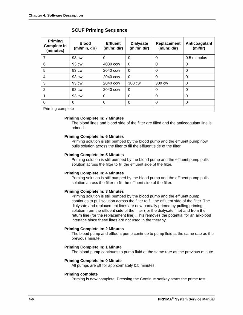
Chapter 4: Software Description
SCUF Priming Sequence
Priming Complete In: 7 MinutesThe blood lines and blood side of the filter are filled and the anticoagulant line is primed.
Priming Complete In: 6 MinutesPriming solution is still pumped by the blood pump and the effluent pump now pulls solution across the filter to fill the effluent side of the filter.
Priming Complete In: 5 MinutesPriming solution is still pumped by the blood pump and the effluent pump pulls solution across the filter to fill the effluent side of the filter.
Priming Complete In: 4 MinutesPriming solution is still pumped by the blood pump and the effluent pump pulls solution across the filter to fill the effluent side of the filter.
Priming Complete In: 3 MinutesPriming solution is still pumped by the blood pump and the effluent pump continues to pull solution across the filter to fill the effluent side of the filter. The dialysate and replacement lines are now partially primed by pulling priming solution from the effluent side of the filter (for the dialysate line) and from the return line (for the replacement line). This removes the potential for an air-blood interface since these lines are not used in the therapy.
Priming Complete In: 2 MinutesThe blood pump and effluent pump continue to pump fluid at the same rate as the previous minute.
Priming Complete In: 1 MinuteThe blood pump continues to pump fluid at the same rate as the previous minute.
Priming Complete In: 0 MinuteAll pumps are off for approximately 0.5 minutes.
Priming completePriming is now complete. Pressing the Continue softkey starts the prime test.
Priming Complete In
(minutes)
Blood (ml/min, dir)
Effluent (ml/hr, dir)
Dialysate(ml/hr, dir)
Replacement (ml/hr, dir)
Anticoagulant (ml/hr)
7 93 cw 0 0 0 0.5 ml bolus6 93 cw 4080 ccw 0 0 05 93 cw 2040 ccw 0 0 04 93 cw 2040 ccw 0 0 03 93 cw 2040 ccw 300 cw 300 cw 02 93 cw 2040 ccw 0 0 01 93 cw 0 0 0 00 0 0 0 0 0Priming complete
4-6 PRISMA® System Service Manual
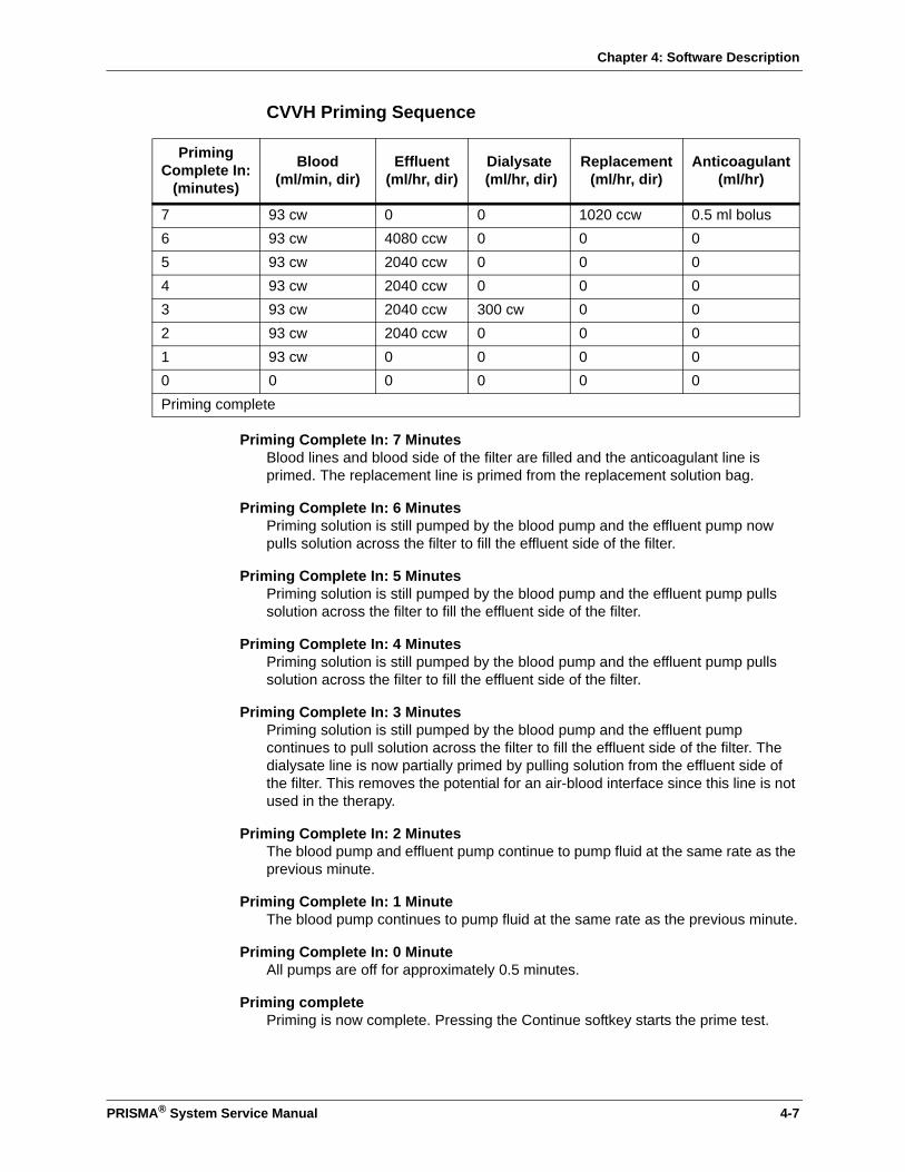
Chapter 4: Software Description
CVVH Priming Sequence
Priming Complete In: 7 MinutesBlood lines and blood side of the filter are filled and the anticoagulant line is primed. The replacement line is primed from the replacement solution bag.
Priming Complete In: 6 MinutesPriming solution is still pumped by the blood pump and the effluent pump now pulls solution across the filter to fill the effluent side of the filter.
Priming Complete In: 5 MinutesPriming solution is still pumped by the blood pump and the effluent pump pulls solution across the filter to fill the effluent side of the filter.
Priming Complete In: 4 MinutesPriming solution is still pumped by the blood pump and the effluent pump pulls solution across the filter to fill the effluent side of the filter.
Priming Complete In: 3 MinutesPriming solution is still pumped by the blood pump and the effluent pump continues to pull solution across the filter to fill the effluent side of the filter. The dialysate line is now partially primed by pulling solution from the effluent side of the filter. This removes the potential for an air-blood interface since this line is not used in the therapy.
Priming Complete In: 2 MinutesThe blood pump and effluent pump continue to pump fluid at the same rate as the previous minute.
Priming Complete In: 1 MinuteThe blood pump continues to pump fluid at the same rate as the previous minute.
Priming Complete In: 0 MinuteAll pumps are off for approximately 0.5 minutes.
Priming completePriming is now complete. Pressing the Continue softkey starts the prime test.
Priming Complete In:
(minutes)
Blood(ml/min, dir)
Effluent (ml/hr, dir)
Dialysate (ml/hr, dir)
Replacement (ml/hr, dir)
Anticoagulant (ml/hr)
7 93 cw 0 0 1020 ccw 0.5 ml bolus6 93 cw 4080 ccw 0 0 05 93 cw 2040 ccw 0 0 04 93 cw 2040 ccw 0 0 03 93 cw 2040 ccw 300 cw 0 02 93 cw 2040 ccw 0 0 01 93 cw 0 0 0 00 0 0 0 0 0Priming complete
PRISMA® System Service Manual 4-7

Chapter 4: Software Description
CVVHD Priming Sequence
Priming Complete In: 7 MinutesThe blood lines and blood side of the filter are filled, the anticoagulant line is primed, and the dialysate line is primed from the dialysate bag.
Priming Complete In: 6 MinutesPriming solution is still pumped by the blood pump and the effluent pump now pulls solution across the filter to fill the effluent side of the filter.
Priming Complete In: 5 MinutesPriming solution is still pumped by the blood pump and the effluent pump pulls solution across the filter to fill the effluent side of the filter.
Priming Complete In: 4 MinutesPriming solution is still pumped by the blood pump and the effluent pump pulls solution across the filter to fill the effluent side of the filter.
Priming Complete In: 3 MinutesPriming solution is still pumped by the blood pump and the effluent pump continues to pull solution across the filter to fill the effluent side of the filter. The replacement line is now partially primed by pulling solution from the return line. This removes the potential for an air-blood interface since this line is not used in the therapy.
Priming Complete In: 2 MinutesThe blood pump and effluent pump continue to pump fluid at the same rate as the previous minute.
Priming Complete In: 1 MinuteThe blood pump continues to pump fluid at the same rate as the previous minute.
Priming Complete In: 0 MinuteAll pumps are off for approximately 0.5 minutes.
Priming completePriming is now complete. Pressing the Continue softkey starts the prime test.
Priming Complete In:
(minutes)
Blood (ml/min, dir)
Effluent (ml/hr, dir)
Dialysate (ml/hr, dir)
Replacement (ml/hr, dir)
Anticoagulant (ml/hr)
7 93 cw 1020 ccw 1020 ccw 0 0.5 ml bolus6 93 cw 4080 ccw 0 0 05 93 cw 2040 ccw 0 0 04 93 cw 2040 ccw 0 0 03 93 cw 2040 ccw 0 300 cw 02 93 cw 2040 ccw 0 0 01 93 cw 0 0 0 00 0 0 0 0 0Priming complete
4-8 PRISMA® System Service Manual
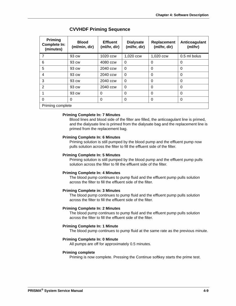
Chapter 4: Software Description
CVVHDF Priming Sequence
Priming Complete In: 7 MinutesBlood lines and blood side of the filter are filled, the anticoagulant line is primed, and the dialysate line is primed from the dialysate bag and the replacement line is primed from the replacement bag.
Priming Complete In: 6 MinutesPriming solution is still pumped by the blood pump and the effluent pump now pulls solution across the filter to fill the effluent side of the filter.
Priming Complete In: 5 MinutesPriming solution is still pumped by the blood pump and the effluent pump pulls solution across the filter to fill the effluent side of the filter.
Priming Complete In: 4 MinutesThe blood pump continues to pump fluid and the effluent pump pulls solution across the filter to fill the effluent side of the filter.
Priming Complete in: 3 MinutesThe blood pump continues to pump fluid and the effluent pump pulls solution across the filter to fill the effluent side of the filter.
Priming Complete In: 2 MinutesThe blood pump continues to pump fluid and the effluent pump pulls solution across the filter to fill the effluent side of the filter.
Priming Complete In: 1 MinuteThe blood pump continues to pump fluid at the same rate as the previous minute.
Priming Complete In: 0 MinuteAll pumps are off for approximately 0.5 minutes.
Priming completePriming is now complete. Pressing the Continue softkey starts the prime test.
Priming Complete In:
(minutes)
Blood (ml/min, dir)
Effluent (ml/hr, dir)
Dialysate (ml/hr, dir)
Replacement(ml/hr, dir)
Anticoagulant (ml/hr)
7 93 cw 1020 ccw 1,020 ccw 1,020 ccw 0.5 ml bolus6 93 cw 4080 ccw 0 0 05 93 cw 2040 ccw 0 0 04 93 cw 2040 ccw 0 0 03 93 cw 2040 ccw 0 0 02 93 cw 2040 ccw 0 0 01 93 cw 0 0 0 00 0 0 0 0 0Priming complete
PRISMA® System Service Manual 4-9
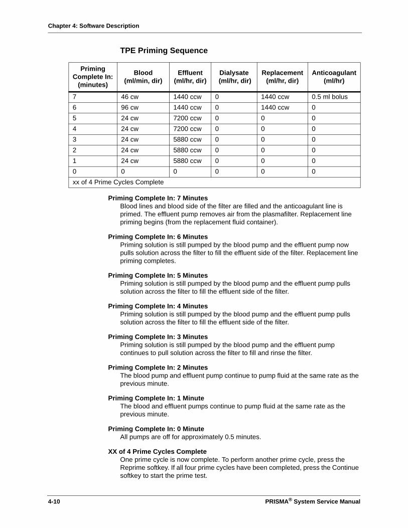
Chapter 4: Software Description
TPE Priming Sequence
Priming Complete In: 7 MinutesBlood lines and blood side of the filter are filled and the anticoagulant line is primed. The effluent pump removes air from the plasmafilter. Replacement line priming begins (from the replacement fluid container).
Priming Complete In: 6 MinutesPriming solution is still pumped by the blood pump and the effluent pump now pulls solution across the filter to fill the effluent side of the filter. Replacement line priming completes.
Priming Complete In: 5 MinutesPriming solution is still pumped by the blood pump and the effluent pump pulls solution across the filter to fill the effluent side of the filter.
Priming Complete In: 4 MinutesPriming solution is still pumped by the blood pump and the effluent pump pulls solution across the filter to fill the effluent side of the filter.
Priming Complete In: 3 MinutesPriming solution is still pumped by the blood pump and the effluent pump continues to pull solution across the filter to fill and rinse the filter.
Priming Complete In: 2 MinutesThe blood pump and effluent pump continue to pump fluid at the same rate as the previous minute.
Priming Complete In: 1 MinuteThe blood and effluent pumps continue to pump fluid at the same rate as the previous minute.
Priming Complete In: 0 MinuteAll pumps are off for approximately 0.5 minutes.
XX of 4 Prime Cycles CompleteOne prime cycle is now complete. To perform another prime cycle, press the Reprime softkey. If all four prime cycles have been completed, press the Continue softkey to start the prime test.
Priming Complete In:
(minutes)
Blood(ml/min, dir)
Effluent (ml/hr, dir)
Dialysate (ml/hr, dir)
Replacement (ml/hr, dir)
Anticoagulant (ml/hr)
7 46 cw 1440 ccw 0 1440 ccw 0.5 ml bolus6 96 cw 1440 ccw 0 1440 ccw 05 24 cw 7200 ccw 0 0 04 24 cw 7200 ccw 0 0 03 24 cw 5880 ccw 0 0 02 24 cw 5880 ccw 0 0 01 24 cw 5880 ccw 0 0 00 0 0 0 0 0xx of 4 Prime Cycles Complete
4-10 PRISMA® System Service Manual

Chapter 4: Software Description
Service Mode
Service Mode consists of two submodes: Calibrate and Diagnose. When the control unit is in Service Mode, all alarms are disabled.
Calibrate
Only two components on the PRISMA Control Unit require Service Mode calibration: the scales and the pressure sensors. The pumps do not require calibration since they use stepper motors.
The control unit will not allow calibration of the scales or the pressure sensors if the same values are entered for at least two of the calibration points, for example, if 0 mmHg is used for both the 0 and the -250 mmHg points while calibrating the access pressure sensor.
Scales
The scales use a 3-point calibration: 0 g, 2600 g, and 5200 g. The three points are used to form two lines which more accurately represent the performance of the scales as demonstrated in Figure 4-1. Two 2600 g weights have been provided with each control unit, and should be used while doing the calibrations.
Figure 4-1. Scales Calibration Curve
Pressures
All pressure sensors require a two point calibration. Each pressure sensor is calibrated at the following pressures:
Access: 0 mmHg and -250 mmHg
Effluent: 0 mmHg and -250 mmHg
Filter: 0 mmHg and +250 mmHg
Return: 0 mmHg and +250 mmHg
5200 g0 g
Applied Weight
2600 g
CalibrationCurve
Scale PerformanceCurve
–3000
0Raw A/DValues
+3000
PRISMA® System Service Manual 4-11
Chapter 4: Software Description
Reposition Transducer: -250 mmHg and +250 mmHg
Diagnose
The Diagnose submode is used to aid in troubleshooting the major subsystems of the PRISMA Control Unit. This mode allows the service technician to isolate each subsystem for testing purposes. The subsystems available from the Diagnose screen include the following:
Pumps
From this screen it is possible to run each pump individually and verify the correct direction and speed by observing the commanded speed versus the tachometer display. Using the 24 Volts softkey, the service technician can test the control and monitor 24 Vdc switch. If the 24 Volts softkey is pressed, all pumps should stop.
Scales
Using the Scales screen, the service technician can monitor the A/D values as well as the calibrated weight in grams for control and monitor of each individual scale. This screen is useful in verifying scale calibration.
Pressures
From this screen it is possible to monitor the millivolt readings as well as the calibrated pressure for each individual pressure sensor. This screen is useful in verifying the pressure sensor calibration.
Lights and Tones
This screen allows the service technician to turn on each individual alarm light as well as listen to each alarm tone.
Air Detector
The Air Detector screen provides test functions for the macro and micro bubble detector functions.
Syringe Pump
When using this screen, the syringe pump can be tested in Continuous Delivery mode or in Bolus Delivery mode. There is an indication of end of travel status and a hex counter to verify the pulses to the syringe pump motor.
Clamp
This screen allows the service technician to operate the return line clamp. The status of the clamp is indicated by an independent optical switch. The Monitor Power softkey turns the 24 Vdc switch Off. When the 24 Vdc switch is not Off via the Monitor Power softkey, the Control Power softkey can toggle it On or Off. If the 24 Vdc switch is set to Off (via either softkey) and the clamp is open, the clamp should close.
Blood Leak Detector
The blood leak detector service screen can be used to test the normalization and self-test functions of the blood leak detector system.
4-12 PRISMA® System Service Manual

Chapter 4: Software Description
Load/Unload
Pressing Load from the Diagnose screen causes the linear actuator to be retracted (towards the rear of the control unit) and the pumps to operate in a similar manner to the loading of a PRISMA Set in Setup mode. Once Load has been pressed, the Unload softkey is displayed in the same softkey location. The Load softkey is always displayed when first entering Diagnose mode even if the linear actuator is in the loaded position. The only way to access the Unload softkey is to first press Load. The time required for load/unload is approximately 7 seconds.
Automatic Reposition System
Pressing Repo on the Diagnose screen allows testing of the automatic reposition system components. Pressing the Valve softkeys (Effluent, Access, Filter, Return) on the Service-Pod Reposition screen displays the corresponding transducer readings. The ARPS transducer reading is automatically displayed on this screen. Pressures can be increased or decreased by pressing Motor (ARPS motor) and changing directions of the pump rotation with the Direction softkey.
Service - Internal Functions
The softkeys on this screen allow testing of softkey functioning, the video display, and watchdog circuitry. In addition, the hours of operation on the PM Timer can be set back to zero.
Test Softkeys: The Softkeys screen is accessed from the Service-Internal screen and allows verification that each of the softkeys is functioning properly. When a numbered softkey is pressed and becomes highlighted, it is working normally.
Test Video: The Video screen is accessed from the Service-Internal screen. The video test illuminates all pixels for 5 seconds, then turns the pixels off for 5 seconds, then displays the Service-Internal screen again. This test allows the service technician to determine if a pixel is burned out, or if a burned in or latent image exists.
Test Watchdog: Pressing either the Test Controller Watch Dog or the Test Monitor Watch Dog softkeys on the Service - Internal screen inhibits the kick signal to the watch dog, causing the timer to expire and reset the control unit.
Set PM Timer Status: The PM Timer records the amount of time since the last preventive maintenance procedure has occurred. Once the timer has reached 6500 hours an advisory alarm occurs that indicates a preventive maintenance is needed. The advisory alarm remains active until the PM timer status is set to zero via the Set PM Timer Status and down arrow softkeys on the Service - Internal screen.
PRISMA® System Service Manual 4-13

Chapter 4: Software Description
This page is left intentionally blank
4-14 PRISMA® System Service Manual

Chapter 5: Service Screens and Calibration
Chapter 5: Service Screens and Calibration
PRISMA Service Screens
PRISMA® service screens are a series of menu- and softkey-driven screens which lead you through calibration procedures, on-line monitoring and testing of the main PRISMA components and systems.
Figure 5-1. PRISMA Softkey Positions
Figure 5-1 shows the number sequence of the softkeys. To access the PRISMA service screens:
1. Simultaneously press and hold the softkeys 4 and 9 as shown above. Press the power switch on and hold the softkeys until the PRISMA screen displays.
2. The machine automatically displays the first screen of the Service Mode, shown in Figure 5-2.
An Exit softkey is provided on every calibration screen so that you may discontinue the calibration routine at any time. Pressing the Exit softkey automatically returns you to the previous Calibrate or Diagnose screen.
1
2
4
3
5 6 7 8
12
11
9
10
PRISMA® System Service Manual 5-1

Chapter 5: Service Screens and Calibration
Service Mode Screen
Figure 5-2. Service Mode Screen
The Service Mode provides access to calibration procedures, on-line control and monitoring, component testing, and configuration menus for the PRISMA system.
Calibrate Softkey
Pressing the Calibrate softkey accesses programmed calibration screens and procedures for:
• Scales – dialysate, effluent, and replacement weight scales
• Pressure sensors – return, effluent, filter, access and automatic repositioning system pressure monitoring
• Setting filter clotting limits
• Setting the real time clock/calendar
• Setting the PRISMA ID number
For a complete description of the screens available under the Calibrate softkey, see “Service-Calibrate Screens” on page 5-4.
Diagnose Softkey
For a complete description of the screens available under the Diagnose softkey, see “Service-Diagnose Screens” on page 5-11.
Restart Softkey
When you press the Restart softkey, the machine exits the Service Mode and then enters the Setup Mode, Choose Patient screen.
CALIBRATE DIAGNOSE
SERVICENOTE: To exit Service Mode, press RESTART.
CRC Values:
Monitor: XXXX Controller: XXXXEnglish: XXXX Italian: XXXXFrench: XXXX Spanish: XXXXGerman: XXXX Swedish XXXXDutch: XXXX
CALIBRATE
EXAMINE ALARMS
RESTART
DIAGNOSE
5-2 PRISMA® System Service Manual

Chapter 5: Service Screens and Calibration
Examine Alarms Softkey
The Examine Alarms softkey is present only if an alarm condition has occurred. When you press this softkey, the display shows the current alarms.
Clear Alarms Softkey
The Clear Alarms softkey is present after pressing the Examine Alarms softkey. If you press the Clear Alarms softkey, the list of alarms disappear from the screen. This function only clears the alarm; it does not clear the condition that is causing the alarm.
PRISMA® System Service Manual 5-3
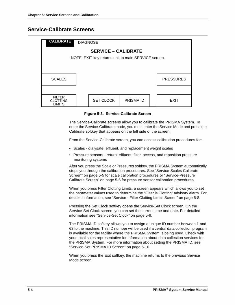
Chapter 5: Service Screens and Calibration
Service-Calibrate Screens
Figure 5-3. Service-Calibrate Screen
The Service-Calibrate screens allow you to calibrate the PRISMA System. To enter the Service-Calibrate mode, you must enter the Service Mode and press the Calibrate softkey that appears on the left side of the screen.
From the Service-Calibrate screen, you can access calibration procedures for:
• Scales - dialysate, effluent, and replacement weight scales
• Pressure sensors - return, effluent, filter, access, and reposition pressure monitoring systems
After you press the Scale or Pressures softkey, the PRISMA System automatically steps you through the calibration procedures. See “Service-Scales Calibrate Screen” on page 5-5 for scale calibration procedures or “Service-Pressure Calibrate Screen” on page 5-6 for pressure sensor calibration procedures.
When you press Filter Clotting Limits, a screen appears which allows you to set the parameter values used to determine the “Filter is Clotting” advisory alarm. For detailed information, see “Service - Filter Clotting Limits Screen” on page 5-8.
Pressing the Set Clock softkey opens the Service-Set Clock screen. On the Service-Set Clock screen, you can set the current time and date. For detailed information see “Service-Set Clock” on page 5-9.
The PRISMA ID softkey allows you to assign a unique ID number between 1 and 63 to the machine. This ID number will be used if a central data collection program is available for the facility where the PRISMA System is being used. Check with your local sales representative for information about data collection services for the PRISMA System. For more information about setting the PRISMA ID, see “Service-Set PRISMA ID Screen” on page 5-10.
When you press the Exit softkey, the machine returns to the previous Service Mode screen.
DIAGNOSE
SERVICE – CALIBRATENOTE: EXIT key returns unit to main SERVICE screen.
CALIBRATE
EXIT
SCALES PRESSURES
FILTERCLOTTING
LIMITSSET CLOCK PRISMA ID
5-4 PRISMA® System Service Manual
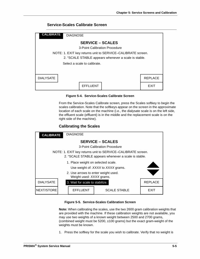
Chapter 5: Service Screens and Calibration
Service-Scales Calibrate Screen
Figure 5-4. Service-Scales Calibrate Screen
From the Service-Scales Calibrate screen, press the Scales softkey to begin the scales calibration. Note that the softkeys appear on the screen in the approximate location of each scale on the machine (i.e., the dialysate scale is on the left side, the effluent scale (effluent) is in the middle and the replacement scale is on the right side of the machine).
Calibrating the Scales
Figure 5-5. Service-Scales Calibration Screen
Note: When calibrating the scales, use the two 2600 gram calibration weights that are provided with the machine. If these calibration weights are not available, you may use two weights of a known weight between 2500 and 2700 grams, (combined weight must be 5200, ±100 grams) but the exact gram-weight of the weights must be known.
1. Press the softkey for the scale you wish to calibrate. Verify that no weight is
DIAGNOSE
SERVICE – SCALES3-Point Calibration Procedure
NOTE: 1. EXIT key returns unit to SERVICE–CALIBRATE screen.
Select a scale to calibrate.
CALIBRATE
EXIT
DIALYSATE REPLACE
EFFLUENT
2. “SCALE STABLE appears whenever a scale is stable.
DIAGNOSE
SERVICE – SCALES3-Point Calibration Procedure
NOTE: 1. EXIT key returns unit to SERVICE–CALIBRATE screen.
1. Place weight on selected scale.Use weight of: XXXX to XXXX grams.
2. Use arrows to enter weight used. Weight used: XXXX grams.
CALIBRATE
EXIT
DIALYSATE REPLACE
NEXT/STORE EFFLUENT
3. Wait for scale to stabilize.
SCALE STABLE
2. “SCALE STABLE appears whenever a scale is stable.
PRISMA® System Service Manual 5-5
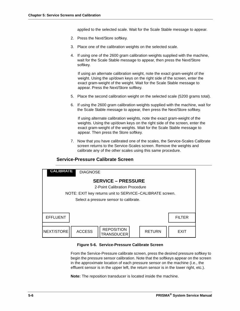
Chapter 5: Service Screens and Calibration
applied to the selected scale. Wait for the Scale Stable message to appear.
2. Press the Next/Store softkey.
3. Place one of the calibration weights on the selected scale.
4. If using one of the 2600 gram calibration weights supplied with the machine, wait for the Scale Stable message to appear, then press the Next/Store softkey.
If using an alternate calibration weight, note the exact gram-weight of the weight. Using the up/down keys on the right side of the screen, enter the exact gram-weight of the weight. Wait for the Scale Stable message to appear. Press the Next/Store softkey.
5. Place the second calibration weight on the selected scale (5200 grams total).
6. If using the 2600 gram calibration weights supplied with the machine, wait for the Scale Stable message to appear, then press the Next/Store softkey.
If using alternate calibration weights, note the exact gram-weight of the weights. Using the up/down keys on the right side of the screen, enter the exact gram-weight of the weights. Wait for the Scale Stable message to appear. Then press the Store softkey.
7. Now that you have calibrated one of the scales, the Service-Scales Calibrate screen returns to the Service-Scales screen. Remove the weights and calibrate any of the other scales using this same procedure.
Service-Pressure Calibrate Screen
Figure 5-6. Service-Pressure Calibrate Screen
From the Service-Pressure calibrate screen, press the desired pressure softkey to begin the pressure sensor calibration. Note that the softkeys appear on the screen in the approximate location of each pressure sensor on the machine (i.e., the effluent sensor is in the upper left, the return sensor is in the lower right, etc.).
Note: The reposition transducer is located inside the machine.
DIAGNOSE
SERVICE – PRESSURE2-Point Calibration Procedure
NOTE: EXIT key returns unit to SERVICE–CALIBRATE screen.Select a pressure sensor to calibrate.
CALIBRATE
EXIT
EFFLUENT FILTER
NEXT/STORE REPOSITIONTRANSDUCER
RETURNACCESS
5-6 PRISMA® System Service Manual

Chapter 5: Service Screens and Calibration
You will need a syringe, a PRISMA pressure test pod (P/N 588125-000) and a calibrated pressure meter to perform this calibration. Note that the pressure sensors are designed to monitor different pressure ranges.
• Effluent pressure, +50 to –350 in CRRT therapies, –50 to +350 mmHg in TPE therapy
• Access pressure, +50 to –250
• Return pressure, –50 to +350
• Filter pressure, –50 to +500
• Reposition pressure, –250 to +250
Next/Store Softkey
The Next/Store softkey is used during the calibration procedure to either advance the machine through the calibration steps or to store calibration data.
Exit Softkey
Pressing the Exit softkey returns the machine to the Service-Calibrate screen.
Calibrating the Pressure Sensors
Figure 5-7. Service-Pressure Calibrate Screen
1. Attach the syringe, pressure test pod, and calibrated pressure meter to the pressure sensor you have selected for calibration.
Note: Use the access pressure sensor when calibrating the reposition transducer.
2. Monitor the calibrated pressure meter and apply a pressure of 0 ±4 mmHg and clamp the tubing. Using the up/down arrow softkeys, adjust the “Actual Pressure” reading until it matches the calibrated pressure meter.
3. Wait for the Sensor Stable message to appear, then press the Next/Store softkey.
DIAGNOSE
SERVICE – PRESSURE2-Point Calibration Procedure
NOTES: (1) EXIT key returns unit to SERVICE-CALIBRATE screen(2) “SENSOR STABLE” appears whenever a sensor is stable
1. Apply pressure on selected sensor. Apply pressure of X to XXX mmHg.
2. Use arrows to enter pressure applied. Pressure applied: XXXX mmHg.
SENSOR STABLE
CALIBRATE
EXIT
EFFLUENT FILTER
NEXT/STORE ACCESS RETURNREPOSITIONTRANSDUCER
3. Wait for sensor to stabilize.
PRISMA® System Service Manual 5-7
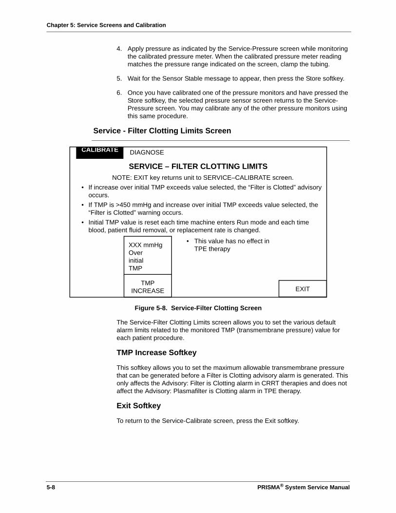
Chapter 5: Service Screens and Calibration
4. Apply pressure as indicated by the Service-Pressure screen while monitoring the calibrated pressure meter. When the calibrated pressure meter reading matches the pressure range indicated on the screen, clamp the tubing.
5. Wait for the Sensor Stable message to appear, then press the Store softkey.
6. Once you have calibrated one of the pressure monitors and have pressed the Store softkey, the selected pressure sensor screen returns to the Service-Pressure screen. You may calibrate any of the other pressure monitors using this same procedure.
Service - Filter Clotting Limits Screen
Figure 5-8. Service-Filter Clotting Screen
The Service-Filter Clotting Limits screen allows you to set the various default alarm limits related to the monitored TMP (transmembrane pressure) value for each patient procedure.
TMP Increase Softkey
This softkey allows you to set the maximum allowable transmembrane pressure that can be generated before a Filter is Clotting advisory alarm is generated. This only affects the Advisory: Filter is Clotting alarm in CRRT therapies and does not affect the Advisory: Plasmafilter is Clotting alarm in TPE therapy.
Exit Softkey
To return to the Service-Calibrate screen, press the Exit softkey.
DIAGNOSE
SERVICE – FILTER CLOTTING LIMITSNOTE: EXIT key returns unit to SERVICE–CALIBRATE screen.
• If increase over initial TMP exceeds value selected, the “Filter is Clotted” advisory occurs.
• If TMP is >450 mmHg and increase over initial TMP exceeds value selected, the “Filter is Clotted” warning occurs.
• Initial TMP value is reset each time machine enters Run mode and each time blood, patient fluid removal, or replacement rate is changed.
• This value has no effect in TPE therapy
CALIBRATE
EXIT
XXX mmHg Over initial TMP
TMPINCREASE
5-8 PRISMA® System Service Manual
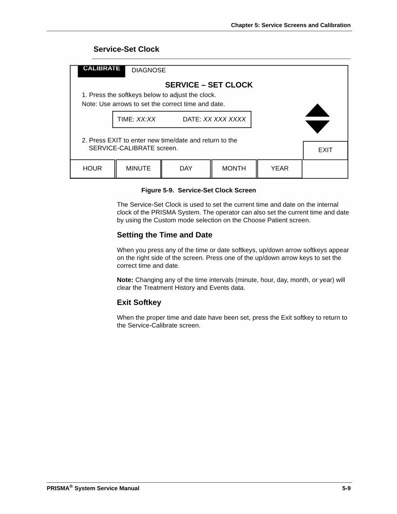
Chapter 5: Service Screens and Calibration
Service-Set Clock
Figure 5-9. Service-Set Clock Screen
The Service-Set Clock is used to set the current time and date on the internal clock of the PRISMA System. The operator can also set the current time and date by using the Custom mode selection on the Choose Patient screen.
Setting the Time and Date
When you press any of the time or date softkeys, up/down arrow softkeys appear on the right side of the screen. Press one of the up/down arrow keys to set the correct time and date.
Note: Changing any of the time intervals (minute, hour, day, month, or year) will clear the Treatment History and Events data.
Exit Softkey
When the proper time and date have been set, press the Exit softkey to return to the Service-Calibrate screen.
DIAGNOSE
SERVICE – SET CLOCK1. Press the softkeys below to adjust the clock.Note: Use arrows to set the correct time and date.
2. Press EXIT to enter new time/date and return to the SERVICE-CALIBRATE screen.
CALIBRATE
EXIT
HOUR DAY MONTHMINUTE YEAR
TIME: XX:XX DATE: XX XXX XXXX
PRISMA® System Service Manual 5-9
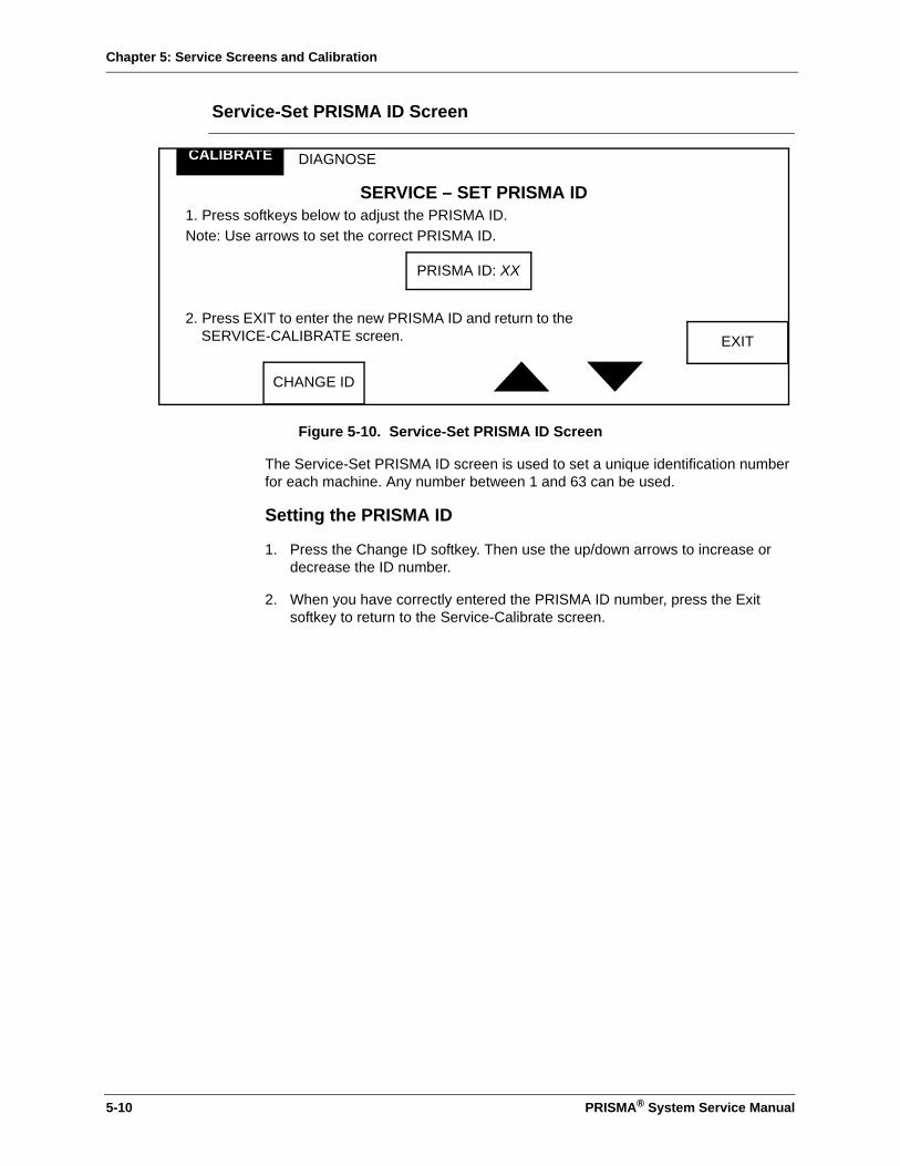
Chapter 5: Service Screens and Calibration
Service-Set PRISMA ID Screen
Figure 5-10. Service-Set PRISMA ID Screen
The Service-Set PRISMA ID screen is used to set a unique identification number for each machine. Any number between 1 and 63 can be used.
Setting the PRISMA ID
1. Press the Change ID softkey. Then use the up/down arrows to increase or decrease the ID number.
2. When you have correctly entered the PRISMA ID number, press the Exit softkey to return to the Service-Calibrate screen.
DIAGNOSE
SERVICE – SET PRISMA ID1. Press softkeys below to adjust the PRISMA ID.Note: Use arrows to set the correct PRISMA ID.
2. Press EXIT to enter the new PRISMA ID and return to the SERVICE-CALIBRATE screen.
CALIBRATE
EXIT
CHANGE ID
PRISMA ID: XX
5-10 PRISMA® System Service Manual
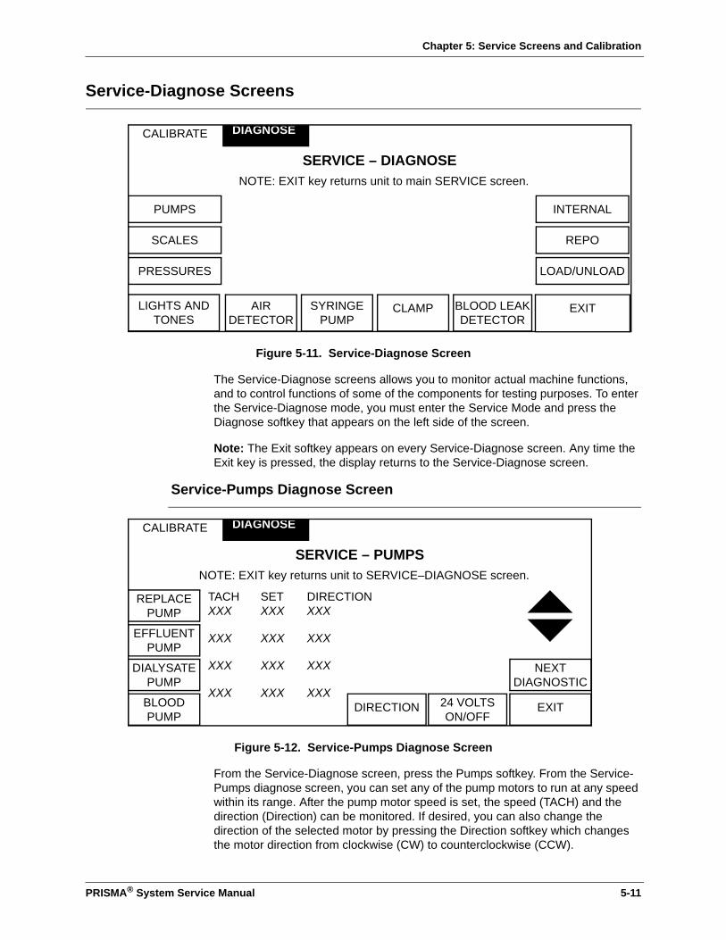
Chapter 5: Service Screens and Calibration
Service-Diagnose Screens
Figure 5-11. Service-Diagnose Screen
The Service-Diagnose screens allows you to monitor actual machine functions, and to control functions of some of the components for testing purposes. To enter the Service-Diagnose mode, you must enter the Service Mode and press the Diagnose softkey that appears on the left side of the screen.
Note: The Exit softkey appears on every Service-Diagnose screen. Any time the Exit key is pressed, the display returns to the Service-Diagnose screen.
Service-Pumps Diagnose Screen
Figure 5-12. Service-Pumps Diagnose Screen
From the Service-Diagnose screen, press the Pumps softkey. From the Service-Pumps diagnose screen, you can set any of the pump motors to run at any speed within its range. After the pump motor speed is set, the speed (TACH) and the direction (Direction) can be monitored. If desired, you can also change the direction of the selected motor by pressing the Direction softkey which changes the motor direction from clockwise (CW) to counterclockwise (CCW).
CALIBRATE
SERVICE – DIAGNOSENOTE: EXIT key returns unit to main SERVICE screen.
DIAGNOSE
PUMPS INTERNAL
EXITLIGHTS AND TONES
BLOOD LEAKDETECTOR
AIRDETECTOR
SYRINGEPUMP
CLAMP
SCALES
PRESSURES
REPO
LOAD/UNLOAD
CALIBRATE
SERVICE – PUMPSNOTE: EXIT key returns unit to SERVICE–DIAGNOSE screen.
TACH XXX
SET XXX
DIRECTION XXX
XXX XXX XXX
XXX XXX XXX
XXX XXX XXX
DIAGNOSE
REPLACEPUMP
EXITBLOODPUMP
24 VOLTSON/OFF
DIRECTION
EFFLUENTPUMP
DIALYSATEPUMP
NEXTDIAGNOSTIC
PRISMA® System Service Manual 5-11
Chapter 5: Service Screens and Calibration
Testing the Pumps
Note: Two or more motors can be tested simultaneously.
1. Select the pump to be tested by pressing one of the pump softkeys (Replace, Effluent, Dialysate or Blood). When you select a pump, the up and down arrow softkeys appear on the right side of the display. Pressing the up arrow softkey increases the pump motor speed, and pressing the down arrow softkey decreases the motor speed.
2. Press the up arrow softkey and release it when the desired pump speed displays under the Set column on the screen. The motor will start as soon as you release the arrow softkey.
Note: To verify that the motor is operating properly, the TACH speed should be the same as the Set speed (±10%).
3. Once the motor is running, you can press the down arrow softkey to decrease the Set motor speed to a lower speed. Again, the TACH speed should be the same as the Set speed (±10%).
4. To change the direction of the motor, press the Direction softkey. The motor will start running in the opposite direction. Note that the motors always start up in the clockwise (cw) direction. The direction of rotation (CW or CCW) is indicated in the column labeled Direction.
Direction Softkey
Pressing the Direction softkey changes the motor direction. The current motor direction is displayed in the softkey label as CW (clockwise) or CCW (counterclockwise).
24 Volts On Softkey
This softkey displays status of the +24 Vdc (on or off). Turning off the 24 Vdc must stop the pumps.
Next Diagnostic Softkey
When you press the Next Diagnostic softkey, the machine leaves the Service-Pumps screen and enters the Service-Scales screen.
5-12 PRISMA® System Service Manual
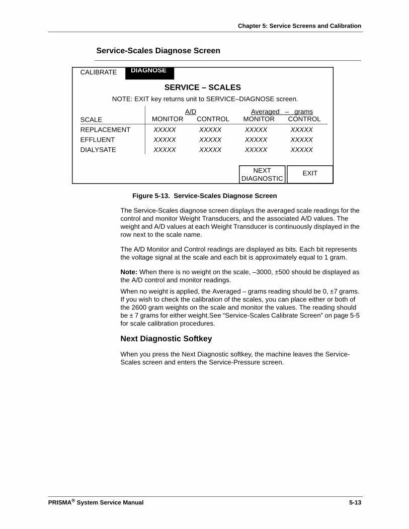
Chapter 5: Service Screens and Calibration
Service-Scales Diagnose Screen
Figure 5-13. Service-Scales Diagnose Screen
The Service-Scales diagnose screen displays the averaged scale readings for the control and monitor Weight Transducers, and the associated A/D values. The weight and A/D values at each Weight Transducer is continuously displayed in the row next to the scale name.
The A/D Monitor and Control readings are displayed as bits. Each bit represents the voltage signal at the scale and each bit is approximately equal to 1 gram.
Note: When there is no weight on the scale, –3000, ±500 should be displayed as the A/D control and monitor readings.
When no weight is applied, the Averaged – grams reading should be 0, ±7 grams. If you wish to check the calibration of the scales, you can place either or both of the 2600 gram weights on the scale and monitor the values. The reading should be ± 7 grams for either weight.See “Service-Scales Calibrate Screen” on page 5-5 for scale calibration procedures.
Next Diagnostic Softkey
When you press the Next Diagnostic softkey, the machine leaves the Service-Scales screen and enters the Service-Pressure screen.
CALIBRATE
SERVICE – SCALESNOTE: EXIT key returns unit to SERVICE–DIAGNOSE screen.
SCALE
A/DMONITOR CONTROL
Averaged – gramsMONITOR CONTROL
REPLACEMENT XXXXX XXXXX XXXXX XXXXXEFFLUENT XXXXX XXXXX XXXXX XXXXXDIALYSATE XXXXX XXXXX XXXXX XXXXX
DIAGNOSE
EXITNEXTDIAGNOSTIC
PRISMA® System Service Manual 5-13
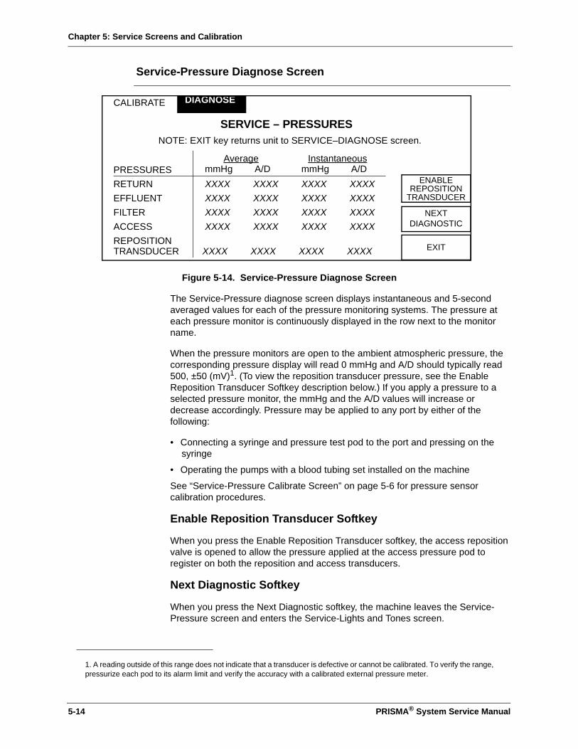
Chapter 5: Service Screens and Calibration
Service-Pressure Diagnose Screen
Figure 5-14. Service-Pressure Diagnose Screen
The Service-Pressure diagnose screen displays instantaneous and 5-second averaged values for each of the pressure monitoring systems. The pressure at each pressure monitor is continuously displayed in the row next to the monitor name.
When the pressure monitors are open to the ambient atmospheric pressure, the corresponding pressure display will read 0 mmHg and A/D should typically read 500, ±50 (mV)1. (To view the reposition transducer pressure, see the Enable Reposition Transducer Softkey description below.) If you apply a pressure to a selected pressure monitor, the mmHg and the A/D values will increase or decrease accordingly. Pressure may be applied to any port by either of the following:
• Connecting a syringe and pressure test pod to the port and pressing on the syringe
• Operating the pumps with a blood tubing set installed on the machine
See “Service-Pressure Calibrate Screen” on page 5-6 for pressure sensor calibration procedures.
Enable Reposition Transducer Softkey
When you press the Enable Reposition Transducer softkey, the access reposition valve is opened to allow the pressure applied at the access pressure pod to register on both the reposition and access transducers.
Next Diagnostic Softkey
When you press the Next Diagnostic softkey, the machine leaves the Service-Pressure screen and enters the Service-Lights and Tones screen.
1. A reading outside of this range does not indicate that a transducer is defective or cannot be calibrated. To verify the range, pressurize each pod to its alarm limit and verify the accuracy with a calibrated external pressure meter.
CALIBRATE
SERVICE – PRESSURESNOTE: EXIT key returns unit to SERVICE–DIAGNOSE screen.
PRESSURES
AveragemmHg A/D
InstantaneousmmHg A/D
RETURN XXXX XXXX XXXX XXXXEFFLUENT XXXX XXXX XXXX XXXXFILTER XXXX XXXX XXXX XXXXACCESS XXXX XXXX XXXX XXXXREPOSITION TRANSDUCER
XXXX
XXXX
XXXX
XXXX
DIAGNOSE
EXIT
NEXTDIAGNOSTIC
ENABLEREPOSITION
TRANSDUCER
5-14 PRISMA® System Service Manual

Chapter 5: Service Screens and Calibration
Service-Lights and Tones Diagnose Screen
Figure 5-15. Service-Lights and Tones Diagnose Screen
Pressing the Lights and Tones softkey from the Service-Diagnose screen allows you to independently test each of the alarm lamps, each of the audible alarm tones, and the speaker. The lamp test softkeys are displayed along the left side of the screen and the alarm tone softkeys are displayed along the bottom of the screen.
Pressing any of the tone softkeys causes the specific tone to be produced by the audible alarm system.
• Warning tone – a continuous stream of beeps
• Malfunction tone – a continuous stream of beeps
• Caution tone – an intermittent double-beep
• Advisory tone – one beep every 10 seconds
Pressing any of the lamp test softkeys silences the tone and causes the specific lamp to illuminate continuously.
Next Diagnostic Softkey
When you press the Next Diagnostic softkey, the machine leaves the Service-Light and Tones screen and enters the Service-Air Detector screen.
CALIBRATE
SERVICE – LIGHTS AND TONESNOTE: EXIT key returns unit to SERVICE–DIAGNOSE screen.
DIAGNOSE
REDLIGHT
EXITADVISORYTONE
WARNINGTONE
MALF.TONE
CAUTIONTONE
YELLOW LIGHT
GREEN LIGHT
NEXTDIAGNOSTIC
PRISMA® System Service Manual 5-15

Chapter 5: Service Screens and Calibration
Service-Air Detector Diagnose Screen
Figure 5-16. Service-Air Detector Screen
The Service-Air Detector screen is used to test the ultrasonic air bubble detector (UABD) system in the PRISMA System. The macrobubble and microbubble detector systems can be tested independently. A fluid-filled tube must be installed in the air bubble detector housing to test the system.
Macro Test Softkey
The Macro Test softkey is used to simulate a macro-size air bubble. When you press the Macro Test softkey, the drive voltage to the ultrasonic air bubble transmitter is decreased, which decreases the ultrasonic air bubble detector receiver voltage. When this voltage is below 1.6 Vdc, the Controller and Monitor Macro Bubble displays a Yes, indicating that the system has detected a macro-size bubble.
Note: When ending the test, the Troub: Yes/No indicator should briefly flash “Yes”.
Micro Test Softkey
The Micro Test softkey is used to simulate micro-size air bubbles. When you press the Micro Test softkey, the drive voltage to the ultrasonic air bubble transmitter is decreased, which decreases the ultrasonic air bubble detector receiver voltage. When this voltage is below 2.2 Vdc, the values in the Micro Count display begin increasing, indicating that the system has detected micro-size bubbles.
Note: The actual values in the Micro Count display are not important, only that the values increase when the Micro Test softkey is pressed. If the values do not increase, this indicates a defective component in the microbubble portion of the ultrasonic air bubble detector circuitry.
Next Diagnostic
When you press the Next Diagnostic softkey, the machine leaves the Service-Air Detector screen and enters the Service-Syringe Pump screen.
CALIBRATE
SERVICE – AIR DETECTORNOTE: EXIT key returns unit to SERVICE–DIAGNOSE screen.
Micro Count: XXXXController Macro Bubble: Yes/NoMonitor Macro Bubble: Yes/NoTroub: Yes/No
DIAGNOSE
EXITMICROTEST
MACROTEST
NEXTDIAGNOSTIC
5-16 PRISMA® System Service Manual

Chapter 5: Service Screens and Calibration
Service-Syringe Pump Diagnose Screen
Figure 5-17. Service-Syringe Pump Diagnose Screen
The Service-Syringe Pump diagnose screen is used to perform various syringe pump test functions and to verify the syringe pump delivery rate.
Continuous Softkey
Pressing this softkey commands the syringe pump to deliver anticoagulant at the rate displayed in the Set Rate column.
Stop Softkey
The Stop softkey commands the syringe pump to stop in the Continuous mode only. This softkey does not affect anticoagulant delivery in the Bolus mode.
Bolus Softkey
Pressing the Bolus softkey commands the syringe pump to deliver a 5 cc bolus of anticoagulant. This bolus amount is programmed and cannot be changed.
Adjust Rate Softkey
When you press the Adjust Rate softkey, an up arrow and a down arrow appear on the right side of the screen, allowing you to vary the syringe pump delivery rate. The maximum delivery rate for the syringe pump is 20 ml/hr.
The rate you select appears in the Set rate display. When the syringe pump is operating, the Monitor rate display value should be changing, indicating that the monitor microprocessor is receiving the stepper motor signal increments.
Next Diagnostic Softkey
Pressing the Next Diagnostic softkey causes the machine to exit the Service-Syringe Pump screen and enter the Service-Clamp screen.
CALIBRATE
SERVICE – SYRINGE PUMPNOTE: EXIT key returns unit to SERVICE–DIAGNOSE screen.
SYRINGE CONTROL:
End of travel: Yes/No
Set rate: XXX ml/hour
Monitor rate: XXX ml/hour
DIAGNOSE
EXITSTOP BOLUS ADJUSTRATE
CONTINUOUS
NEXTDIAGNOSTIC
PRISMA® System Service Manual 5-17
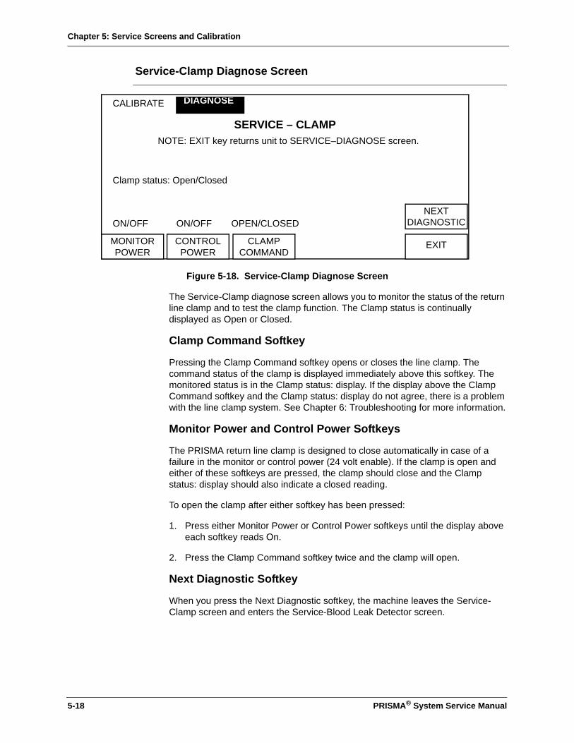
Chapter 5: Service Screens and Calibration
Service-Clamp Diagnose Screen
Figure 5-18. Service-Clamp Diagnose Screen
The Service-Clamp diagnose screen allows you to monitor the status of the return line clamp and to test the clamp function. The Clamp status is continually displayed as Open or Closed.
Clamp Command Softkey
Pressing the Clamp Command softkey opens or closes the line clamp. The command status of the clamp is displayed immediately above this softkey. The monitored status is in the Clamp status: display. If the display above the Clamp Command softkey and the Clamp status: display do not agree, there is a problem with the line clamp system. See Chapter 6: Troubleshooting for more information.
Monitor Power and Control Power Softkeys
The PRISMA return line clamp is designed to close automatically in case of a failure in the monitor or control power (24 volt enable). If the clamp is open and either of these softkeys are pressed, the clamp should close and the Clamp status: display should also indicate a closed reading.
To open the clamp after either softkey has been pressed:
1. Press either Monitor Power or Control Power softkeys until the display above each softkey reads On.
2. Press the Clamp Command softkey twice and the clamp will open.
Next Diagnostic Softkey
When you press the Next Diagnostic softkey, the machine leaves the Service-Clamp screen and enters the Service-Blood Leak Detector screen.
CALIBRATE
SERVICE – CLAMPNOTE: EXIT key returns unit to SERVICE–DIAGNOSE screen.
Clamp status: Open/Closed
ON/OFF ON/OFF OPEN/CLOSED
DIAGNOSE
EXIT
NEXTDIAGNOSTIC
MONITORPOWER
CONTROLPOWER
CLAMPCOMMAND
5-18 PRISMA® System Service Manual
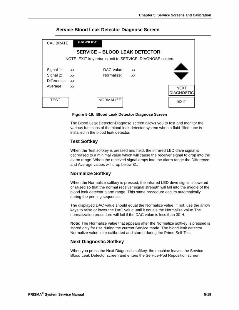
Chapter 5: Service Screens and Calibration
Service-Blood Leak Detector Diagnose Screen
Figure 5-19. Blood Leak Detector Diagnose Screen
The Blood Leak Detector-Diagnose screen allows you to test and monitor the various functions of the blood leak detector system when a fluid-filled tube is installed in the blood leak detector.
Test Softkey
When the Test softkey is pressed and held, the infrared LED drive signal is decreased to a minimal value which will cause the receiver signal to drop into the alarm range. When the received signal drops into the alarm range the Difference and Average values will drop below 81.
Normalize Softkey
When the Normalize softkey is pressed, the infrared LED drive signal is lowered or raised so that the normal receiver signal strength will fall into the middle of the blood leak detector alarm range. This same procedure occurs automatically during the priming sequence.
The displayed DAC value should equal the Normalize value. If not, use the arrow keys to raise or lower the DAC value until it equals the Normalize value.The normalization procedure will fail if the DAC value is less than 30 H.
Note: The Normalize value that appears after the Normalize softkey is pressed is stored only for use during the current Service mode. The blood leak detector Normalize value is re-calibrated and stored during the Prime Self-Test.
Next Diagnostic Softkey
When you press the Next Diagnostic softkey, the machine leaves the Service-Blood Leak Detector screen and enters the Service-Pod Reposition screen.
CALIBRATE
SERVICE – BLOOD LEAK DETECTORNOTE: EXIT key returns unit to SERVICE–DIAGNOSE screen.
Signal 1: xx DAC Value: xxSignal 2: xx Normalize: xxDifference: xxAverage: xx
DIAGNOSE
EXIT
NEXTDIAGNOSTIC
TEST NORMALIZE
PRISMA® System Service Manual 5-19

Chapter 5: Service Screens and Calibration
Signal 1 and Signal 2
Signal 1 represents the receiver signal when there is no transmitter LED signal present. This value represents the amount of ambient infrared light in the surrounding area.
Signal 2 represents the receiver signal when the normal transmitter LED signal is present. This value represents the signal that is transmitted through the fluid-filled tubing plus the ambient infrared light in the blood leak detector housing.
Difference and Average
The Signal 2 value minus the Signal 1 value is displayed at the Difference display. The difference between Signal 1 and Signal 2 values enables the system to negate any environmental changes that may affect the receiver signal. Since Signal 1 is a relatively constant value, a decrease in Signal 2 value (a lower receiver signal) may indicate blood or other obstructions in the blood leak detector. An increased Signal 2 value (a higher receiver signal) may indicate that there is no tubing in the detector housing. The Difference value should be between 167 and 184 after a correct normalization.
The Average value represents the average of the Difference value over a period of time. The initial Average value appears between 2.5 and 5 seconds after the initial Difference value is determined. The Average value can indicate that an alarm or malfunction condition exists. By using an averaged value, any short term variances, such as air bubbles, will not cause false blood leak alarms.
Note: The Average value must remain at an alarm level (less than or equal to 81) for 22 seconds or more to generate the Blood Leak alarm.
5-20 PRISMA® System Service Manual
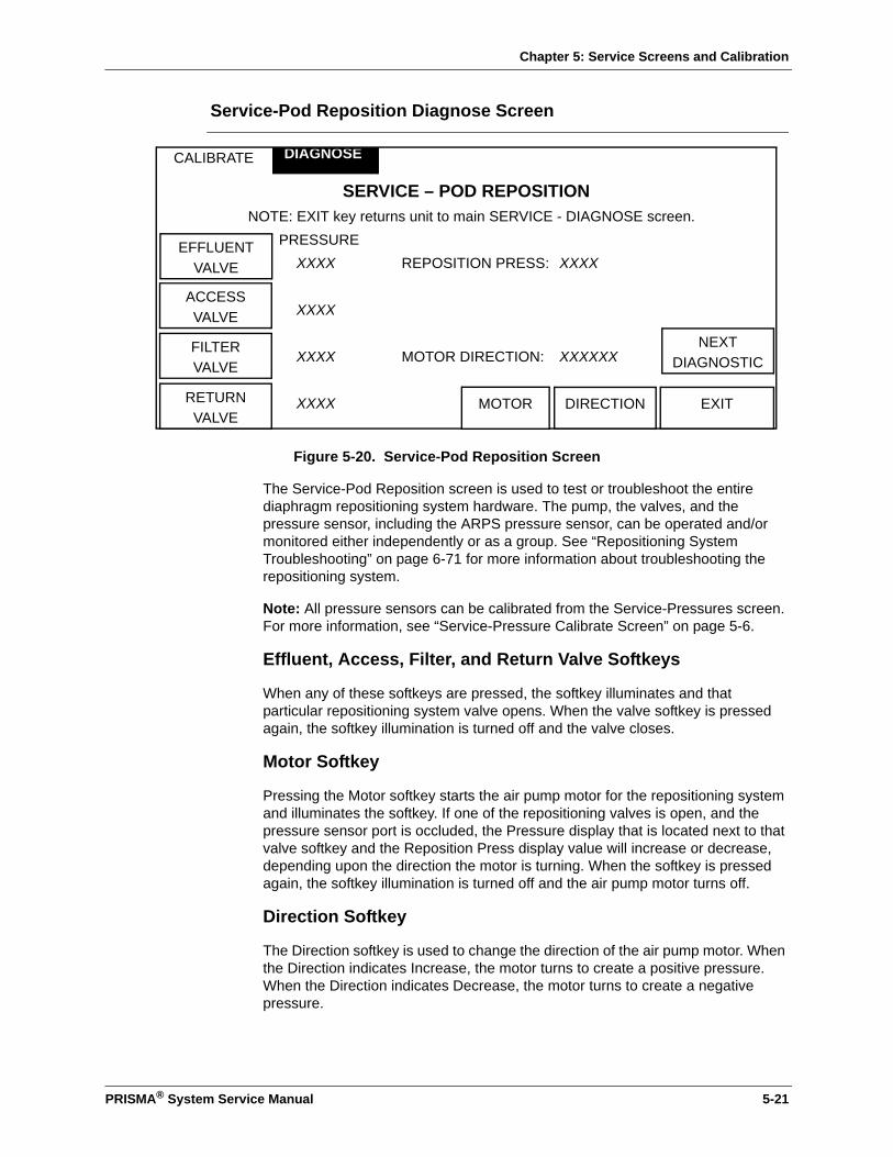
Chapter 5: Service Screens and Calibration
Service-Pod Reposition Diagnose Screen
Figure 5-20. Service-Pod Reposition Screen
The Service-Pod Reposition screen is used to test or troubleshoot the entire diaphragm repositioning system hardware. The pump, the valves, and the pressure sensor, including the ARPS pressure sensor, can be operated and/or monitored either independently or as a group. See “Repositioning System Troubleshooting” on page 6-71 for more information about troubleshooting the repositioning system.
Note: All pressure sensors can be calibrated from the Service-Pressures screen. For more information, see “Service-Pressure Calibrate Screen” on page 5-6.
Effluent, Access, Filter, and Return Valve Softkeys
When any of these softkeys are pressed, the softkey illuminates and that particular repositioning system valve opens. When the valve softkey is pressed again, the softkey illumination is turned off and the valve closes.
Motor Softkey
Pressing the Motor softkey starts the air pump motor for the repositioning system and illuminates the softkey. If one of the repositioning valves is open, and the pressure sensor port is occluded, the Pressure display that is located next to that valve softkey and the Reposition Press display value will increase or decrease, depending upon the direction the motor is turning. When the softkey is pressed again, the softkey illumination is turned off and the air pump motor turns off.
Direction Softkey
The Direction softkey is used to change the direction of the air pump motor. When the Direction indicates Increase, the motor turns to create a positive pressure. When the Direction indicates Decrease, the motor turns to create a negative pressure.
CALIBRATE
SERVICE – POD REPOSITIONNOTE: EXIT key returns unit to main SERVICE - DIAGNOSE screen.
PRESSUREXXXX REPOSITION PRESS: XXXX
XXXX
XXXX MOTOR DIRECTION: XXXXXX
XXXX
DIAGNOSE
EXITRETURNVALVE
MOTOR
EFFLUENTVALVE
ACCESSVALVE
FILTERVALVE
DIRECTION
NEXTDIAGNOSTIC
PRISMA® System Service Manual 5-21

Chapter 5: Service Screens and Calibration
Pressure and Reposition Press Display
The Pressure reading at each of the repositioning transducers is displayed next to the particular valve softkey. The Pressure reading at the repositioning transducer is displayed next to the Reposition Press display. When the repositioning system is pressurized by the air pump under normal circumstances, the Pressure display and the Reposition Press display of any selected or opened valve should read within ±4 mmHg of each other.
Note: For testing purposes, note that the reposition pressure sensor has a lower resolution than the other pressure sensors. Therefore, the Reposition Press value should be considered as less accurate.
Next Diagnostic Softkey
When you press the Next Diagnostic softkey, the machine leaves the Service-Pod Reposition screen and enters the Service-Internal screen.
5-22 PRISMA® System Service Manual
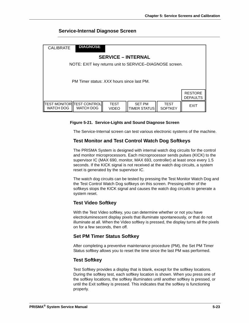
Chapter 5: Service Screens and Calibration
Service-Internal Diagnose Screen
Figure 5-21. Service-Lights and Sound Diagnose Screen
The Service-Internal screen can test various electronic systems of the machine.
Test Monitor and Test Control Watch Dog Softkeys
The PRISMA System is designed with internal watch dog circuits for the control and monitor microprocessors. Each microprocessor sends pulses (KICK) to the supervisor IC (MAX 690, monitor, MAX 693, controller) at least once every 1.5 seconds. If the KICK signal is not received at the watch dog circuits, a system reset is generated by the supervisor IC.
The watch dog circuits can be tested by pressing the Test Monitor Watch Dog and the Test Control Watch Dog softkeys on this screen. Pressing either of the softkeys stops the KICK signal and causes the watch dog circuits to generate a system reset.
Test Video Softkey
With the Test Video softkey, you can determine whether or not you have electroluminescent display pixels that illuminate spontaneously, or that do not illuminate at all. When the Video softkey is pressed, the display turns all the pixels on for a few seconds, then off.
Set PM Timer Status Softkey
After completing a preventive maintenance procedure (PM), the Set PM Timer Status softkey allows you to reset the time since the last PM was performed.
Test Softkey
Test Softkey provides a display that is blank, except for the softkey locations. During the softkey test, each softkey location is shown. When you press one of the softkey locations, the softkey illuminates until another softkey is pressed, or until the Exit softkey is pressed. This indicates that the softkey is functioning properly.
CALIBRATE
SERVICE – INTERNALNOTE: EXIT key returns unit to SERVICE–DIAGNOSE screen.
PM Timer status: XXX hours since last PM.
DIAGNOSE
EXITTEST MONITORWATCH DOG
TEST CONTROLWATCH DOG
TESTVIDEO
SET PMTIMER STATUS
TESTSOFTKEY
RESTORE DEFAULTS
PRISMA® System Service Manual 5-23

Chapter 5: Service Screens and Calibration
Restore Defaults Softkey
Exit Softkey
Pressing the Exit softkey returns the machine to the Service-Diagnose screen.
Test Mode
Figure 5-22. Test Mode Screen
The Test mode enables you to override the Prime sequence and advance to the I/O status screens to check the machine’s operation.
To enter the Test mode:
1. Turn on the machine and proceed through a normal start-up operation.
2. At the Choose Patient screen, press the softkeys in the order shown in Figure 5-22 (A, then B, then C, then D).
3. When the Test Mode message appears, continue with the normal setup procedure as described in Setup Mode on page 2-12.
Note: All alarms are active during the Test mode.
When in Test Mode, the I/O Status screen will have an additional softkey available labeled Scales. When this key is pressed you enter the Test Mode - Scales screen, which displays the scale values while performing a normal run.
Pressing the Restore Defaults softkey twice will return ALL calibration values and any custom parameters to the manufacturer’s default values. Use caution before pressing this softkey.
Do not perform a patient treatment while the system is in Test mode.
CAUTION
!
ADB
C
WARNING
!
5-24 PRISMA® System Service Manual

Chapter 5: Service Screens and Calibration
In the Scales screen, a key appears for Pumps. Pressing the Pumps key enables the Test Mode - Pumps screen, which displays the pump speeds while performing a normal run.
In the Pumps screen, a softkey appears for TMPa if performing TPE therapy. Pressing the TMPa softkey enables the Test Mode - TMPa screen which displays the TMPa self-calibration values and the corrections being used to calculate TMPa.
Pressing the EXIT softkey from any of these screens returns you to the I/O Status Screen. From the TMPa screen you can return to the Pumps screen. From the Pumps screen you can return to the Scales screen, or activate either of two additional items:
• The Self Test key initiates the Self Test procedure.
• The Screen Test key puts the Monitor into the Prime mode, and the Control into the Treatment mode. Since the processors no longer agree, a Malfunction - Command Path alarm is generated.
To clear this alarm:
1. Shut off the machine and restart it in the Service mode.
2. From the main Service screen, press the Examine Alarms key.
3. From the Alarms display screen, press the Clear Alarms key.
4. You may then go into a normal run mode, or reenter the Test mode.
PRISMA® System Service Manual 5-25

Chapter 5: Service Screens and Calibration
This page is left intentionally blank
5-26 PRISMA® System Service Manual
Chapter 6: Alarm System and Troubleshooting
Chapter 6: Alarm System and Troubleshooting
The alarm screens give on-line instructions for responding to most alarm situations. Under certain circumstances, however, the alarm system cannot give the necessary detailed instructions. This chapter of the manual provides the additional information that may be needed.
This chapter also contains instructions for Manual Termination of Treatment procedures (with and without returning blood to the patient), Pod Diaphragm Reposition procedures, and Air Removal procedures.
The PRISMA Control Unit continually monitors itself and the PRISMA Set for proper functioning during operation. If an abnormal situation occurs, the control unit signals a Warning, Malfunction, Caution, or Advisory alarm.
The operator is notified of an alarm condition via a red or yellow status light, an audible alarm, and an Alarm screen on the display. Each Alarm screen has instructions for how to respond to the alarm and provides a Mute key, which allows the operator to temporarily silence the alarm (for 2 minutes). When applicable, a Help screen is available to provide additional information.
PRISMA® System Service Manual 6-1

Chapter 6: Alarm System and Troubleshooting
• When responding to any alarm, carefully follow the instructions on the displayed Alarm screen and its associated Help screen.
• To clear some alarms, the PRISMA Control Unit must override the alarm for a brief time (60 seconds). The Alarm screen notifies the operator that the alarm will be overridden if the OVERRIDE softkey is pressed. A new alarm for the same condition cannot occur during the override period. Therefore, carefully observe the set and all operation during the override period. If the alarm condition is still present after the override period, the control unit issues a new alarm.
• Do not override the same alarm repeatedly. End treatment and service the machine.
• If power is lost to the PRISMA Control Unit, the patient can be manually disconnected from the set. If performing a Manual Termination With Blood Return, visually check for air in the blood return line until the patient is disconnected.
• The control unit may not be able to detect disconnections of the set from the patient’s catheter. Additionally, for TPE therapy, the unit may not be able to detect disconnections from the saline bag or from the clamped or unclamped clear and red segments of the access line. Carefully observe the set and all operation while using the PRISMA System.
WARNINGS
!
6-2 PRISMA® System Service Manual
Chapter 6: Alarm System and Troubleshooting
Alarm Troubleshooting Contents
Warning Alarms . . . . . . . . . . . . . . . . . . . . . . . . . . . . . . . . . . . . . . . . . . . . . . . . .6-7Control Unit Actions . . . . . . . . . . . . . . . . . . . . . . . . . . . . . . . . . . . . . . . . . . 6-7Operator Response . . . . . . . . . . . . . . . . . . . . . . . . . . . . . . . . . . . . . . . . . . 6-7Overridden Warning Alarms. . . . . . . . . . . . . . . . . . . . . . . . . . . . . . . . . . . . 6-7
Malfunction Alarms . . . . . . . . . . . . . . . . . . . . . . . . . . . . . . . . . . . . . . . . . . . . . . .6-8Control Unit Actions . . . . . . . . . . . . . . . . . . . . . . . . . . . . . . . . . . . . . . . . . . 6-8Operator Response . . . . . . . . . . . . . . . . . . . . . . . . . . . . . . . . . . . . . . . . . . 6-8Overridden Malfunction Alarms . . . . . . . . . . . . . . . . . . . . . . . . . . . . . . . . . 6-9
Caution Alarms . . . . . . . . . . . . . . . . . . . . . . . . . . . . . . . . . . . . . . . . . . . . . . . . . .6-9Control Unit Actions . . . . . . . . . . . . . . . . . . . . . . . . . . . . . . . . . . . . . . . . . . 6-9Operator Response . . . . . . . . . . . . . . . . . . . . . . . . . . . . . . . . . . . . . . . . . . 6-9
Advisory Alarms . . . . . . . . . . . . . . . . . . . . . . . . . . . . . . . . . . . . . . . . . . . . . . . 6-10Control Unit Actions . . . . . . . . . . . . . . . . . . . . . . . . . . . . . . . . . . . . . . . . . 6-10Operator Response . . . . . . . . . . . . . . . . . . . . . . . . . . . . . . . . . . . . . . . . . 6-10Overridden Advisory Alarms . . . . . . . . . . . . . . . . . . . . . . . . . . . . . . . . . . 6-10
Alarm Priorities . . . . . . . . . . . . . . . . . . . . . . . . . . . . . . . . . . . . . . . . . . . . . . . . 6-11
Priority of PRISMA System Alarms. . . . . . . . . . . . . . . . . . . . . . . . . . . . . . . . . 6-11
Warning Alarms Troubleshooting . . . . . . . . . . . . . . . . . . . . . . . . . . . . . . . . . . 6-15
Access disconnection . . . . . . . . . . . . . . . . . . . . . . . . . . . . . . . . . . . . . . . . . . . 6-15Access pressure (Access pressure extremely negative.) . . . . . . . . . . . . 6-16Air in blood . . . . . . . . . . . . . . . . . . . . . . . . . . . . . . . . . . . . . . . . . . . . . . . . 6-16Blood leak detected . . . . . . . . . . . . . . . . . . . . . . . . . . . . . . . . . . . . . . . . . 6-17Filter is clotted . . . . . . . . . . . . . . . . . . . . . . . . . . . . . . . . . . . . . . . . . . . . . 6-18Filter pressure (Filter pressure extremely positive.) . . . . . . . . . . . . . . . . . 6-18Micro air in blood . . . . . . . . . . . . . . . . . . . . . . . . . . . . . . . . . . . . . . . . . . . 6-19Plasmafilter is clotted . . . . . . . . . . . . . . . . . . . . . . . . . . . . . . . . . . . . . . . . 6-19Power failure . . . . . . . . . . . . . . . . . . . . . . . . . . . . . . . . . . . . . . . . . . . . . . 6-20Return disconnection . . . . . . . . . . . . . . . . . . . . . . . . . . . . . . . . . . . . . . . . 6-20Return pressure (Return pressure extremely positive.) . . . . . . . . . . . . . . 6-21Set disconnection. . . . . . . . . . . . . . . . . . . . . . . . . . . . . . . . . . . . . . . . . . . 6-22
Malfunction Alarms Troubleshooting . . . . . . . . . . . . . . . . . . . . . . . . . . . . . . . 6-23
Air detector (Air detector failed self-tests.) . . . . . . . . . . . . . . . . . . . . . . . . . . . 6-23BB memory failure (Initialization test failed.) . . . . . . . . . . . . . . . . . . . . . . 6-23Blood leak detector . . . . . . . . . . . . . . . . . . . . . . . . . . . . . . . . . . . . . . . . . 6-24Blood leak detector failed self-tests. . . . . . . . . . . . . . . . . . . . . . . . . . . . . 6-24Blood pump (Rate is incorrect.) . . . . . . . . . . . . . . . . . . . . . . . . . . . . . . . . 6-24Checksum interrupted (Cannot verify data in block: XX) . . . . . . . . . . . . . 6-25Clamp stuck closed . . . . . . . . . . . . . . . . . . . . . . . . . . . . . . . . . . . . . . . . . 6-25Clamp stuck open . . . . . . . . . . . . . . . . . . . . . . . . . . . . . . . . . . . . . . . . . . 6-26Command path (Internal malfunction.) . . . . . . . . . . . . . . . . . . . . . . . . . . . 6-26Dialysate pump (Rate is incorrect.) . . . . . . . . . . . . . . . . . . . . . . . . . . . . . 6-26DPRAM failure (Internal malfunction.) . . . . . . . . . . . . . . . . . . . . . . . . . . . 6-27Effluent pump (Rate is incorrect.). . . . . . . . . . . . . . . . . . . . . . . . . . . . . . . 6-27Normalize BLD failed . . . . . . . . . . . . . . . . . . . . . . . . . . . . . . . . . . . . . . . . 6-27Parity error (Memory malfunction.). . . . . . . . . . . . . . . . . . . . . . . . . . . . . . 6-28Pressure zero test . . . . . . . . . . . . . . . . . . . . . . . . . . . . . . . . . . . . . . . . . . 6-28Prime self-test . . . . . . . . . . . . . . . . . . . . . . . . . . . . . . . . . . . . . . . . . . . . . 6-28Prime Self-test (Failure Due To: TMPa calibration failed.) . . . . . . . . . . . . 6-31
PRISMA® System Service Manual 6-3
Chapter 6: Alarm System and Troubleshooting
RAM R/W failure (Initialization test failed.) . . . . . . . . . . . . . . . . . . . . . . . . 6-31Replacement pump . . . . . . . . . . . . . . . . . . . . . . . . . . . . . . . . . . . . . . . . . 6-32Scales (Scale out of calibration: XXXX) . . . . . . . . . . . . . . . . . . . . . . . . . . 6-32Scale zero test . . . . . . . . . . . . . . . . . . . . . . . . . . . . . . . . . . . . . . . . . . . . . 6-32Self-test failure . . . . . . . . . . . . . . . . . . . . . . . . . . . . . . . . . . . . . . . . . . . . . 6-33Stuck key . . . . . . . . . . . . . . . . . . . . . . . . . . . . . . . . . . . . . . . . . . . . . . . . . 6-33Syringe pump (Rate is incorrect.). . . . . . . . . . . . . . . . . . . . . . . . . . . . . . . 6-33
Caution Alarms Troubleshooting . . . . . . . . . . . . . . . . . . . . . . . . . . . . . . . . . . 6-34Anticoag syringe empty . . . . . . . . . . . . . . . . . . . . . . . . . . . . . . . . . . . . . . 6-34Dialysate bag empty (CRRT only) . . . . . . . . . . . . . . . . . . . . . . . . . . . . . . 6-34Dialysate weight (Incorrect weight change detected.) . . . . . . . . . . . . . . . 6-35Effluent bag full . . . . . . . . . . . . . . . . . . . . . . . . . . . . . . . . . . . . . . . . . . . . 6-36Effluent pressure (Effluent pressure too negative). . . . . . . . . . . . . . . . . . 6-36Effluent weight (Incorrect weight change detected.) . . . . . . . . . . . . . . . . 6-37Excess Pt Fluid Loss or Gain . . . . . . . . . . . . . . . . . . . . . . . . . . . . . . . . . . 6-38Replacement bag empty . . . . . . . . . . . . . . . . . . . . . . . . . . . . . . . . . . . . . 6-38Replacement container empty . . . . . . . . . . . . . . . . . . . . . . . . . . . . . . . . . 6-38Replacement weight (Incorrect weight change detected.) . . . . . . . . . . . . 6-39TMP excessive. . . . . . . . . . . . . . . . . . . . . . . . . . . . . . . . . . . . . . . . . . . . . 6-40TMPa excessive (Access transmembrane pressure exceeds +100
mmHg.) . . . . . . . . . . . . . . . . . . . . . . . . . . . . . . . . . . . . . . . . . . . . . . . . . 6-40
TPE prescription delivered (Prescribed replacement fluid input has been achieved.) . . . . . . . . . . . . . . . . . . . . . . . . . . . . . . . . . . . . . . . . . . . 6-41
Advisory Alarms Troubleshooting . . . . . . . . . . . . . . . . . . . . . . . . . . . . . . . . . . 6-42Access disconnection cannot be detected . . . . . . . . . . . . . . . . . . . . . . . . 6-42Access pressure. . . . . . . . . . . . . . . . . . . . . . . . . . . . . . . . . . . . . . . . . . . . 6-42Access too negative . . . . . . . . . . . . . . . . . . . . . . . . . . . . . . . . . . . . . . . . . 6-43Anticoag syringe empty . . . . . . . . . . . . . . . . . . . . . . . . . . . . . . . . . . . . . . 6-43Bag placement (Dialysate scale indicates an incorrect bag
placement.) . . . . . . . . . . . . . . . . . . . . . . . . . . . . . . . . . . . . . . . . . . . . . . 6-43Bag placement (Effluent scale indicates an incorrect bag
placement.) . . . . . . . . . . . . . . . . . . . . . . . . . . . . . . . . . . . . . . . . . . . . . . 6-44Bag placement (Replacement scale indicates an incorrect bag
placement.) . . . . . . . . . . . . . . . . . . . . . . . . . . . . . . . . . . . . . . . . . . . . . . 6-44Blood flow stopped (Machine has been left in the Stop screen
for 60 seconds.) . . . . . . . . . . . . . . . . . . . . . . . . . . . . . . . . . . . . . . . . . . . 6-44Filter is clotting (TMP and/or DP filter is rising.) . . . . . . . . . . . . . . . . . . . . 6-45Periodic self-test in progress . . . . . . . . . . . . . . . . . . . . . . . . . . . . . . . . . . 6-46Plasmafilter is clotting (Plasmafilter is beginning to clot or
DP filter is rising.) . . . . . . . . . . . . . . . . . . . . . . . . . . . . . . . . . . . . . . . . . 6-47Return disconnection cannot be detected . . . . . . . . . . . . . . . . . . . . . . . . 6-48Return pressure (Return pressure is dropping.). . . . . . . . . . . . . . . . . . . . 6-48Return too positive . . . . . . . . . . . . . . . . . . . . . . . . . . . . . . . . . . . . . . . . . . 6-48Time for preventive maintenance. . . . . . . . . . . . . . . . . . . . . . . . . . . . . . . 6-49Time to change set. . . . . . . . . . . . . . . . . . . . . . . . . . . . . . . . . . . . . . . . . . 6-49TMP too high (Transmembrane pressure has reached user-set
pressure limit.) . . . . . . . . . . . . . . . . . . . . . . . . . . . . . . . . . . . . . . . . . . . . 6-49TMPa too high (Access transmembrane pressure has reached
user-set pressure limit.) . . . . . . . . . . . . . . . . . . . . . . . . . . . . . . . . . . . . . 6-50
Additional Troubleshooting . . . . . . . . . . . . . . . . . . . . . . . . . . . . . . . . . . . . . . . 6-50Cartridge carrier is flush with front panel of machine, so that a set
cannot be loaded. . . . . . . . . . . . . . . . . . . . . . . . . . . . . . . . . . . . . . . . . . 6-50
6-4 PRISMA® System Service Manual
Chapter 6: Alarm System and Troubleshooting
Display goes blank momentarily, then screen reappears. . . . . . . . . . . . . 6-50Display goes blank or logo screen fails to leave display; status
lights may still be on; no buzzer. . . . . . . . . . . . . . . . . . . . . . . . . . . . . . . 6-51Display goes blank; status lights go off; non-mutable buzzer
sounds. . . . . . . . . . . . . . . . . . . . . . . . . . . . . . . . . . . . . . . . . . . . . . . . . . 6-51Effluent bag is tinged pink or red.. . . . . . . . . . . . . . . . . . . . . . . . . . . . . . . 6-52Leakage from set connections. . . . . . . . . . . . . . . . . . . . . . . . . . . . . . . . . 6-52Softkeys won’t work. . . . . . . . . . . . . . . . . . . . . . . . . . . . . . . . . . . . . . . . . 6-52Unable to Normalize BLD. . . . . . . . . . . . . . . . . . . . . . . . . . . . . . . . . . . . . 6-53
Component and System Troubleshooting
Scale Troubleshooting . . . . . . . . . . . . . . . . . . . . . . . . . . . . . . . . . . . . . . . . .6-54The Lower End of One of the Scale Readings is Inaccurate . . . . . . . . .6-54The Higher End of One of the Scale Readings is Inaccurate . . . . . . . . .6-55Scale Calibration Changes Whenever Power is Turned Off . . . . . . . . . .6-55One Scale is Not Working (The readings do not change) . . . . . . . . . . .6-56All Scale Values Are Not Functioning . . . . . . . . . . . . . . . . . . . . . . . . . . .6-57
Pressure Monitor Troubleshooting . . . . . . . . . . . . . . . . . . . . . . . . . . . . . . . .6-58One of the Pressure Readings is Inaccurate or One of the Pressure
Readings Does Not Change (remains at a single value) . . . . . . . . . . .6-58None of the Pressure Readings are Changing . . . . . . . . . . . . . . . . . . . .6-58Effluent and Return Pressures Not Functioning . . . . . . . . . . . . . . . . . . .6-59Filter and Access Pressures Not Functioning . . . . . . . . . . . . . . . . . . . . .6-60Pressures Have to be Recalibrated after the Machine Power is
Turned Off, Then On . . . . . . . . . . . . . . . . . . . . . . . . . . . . . . . . . . . . . .6-60Air Bubble Detector Troubleshooting . . . . . . . . . . . . . . . . . . . . . . . . . . .6-61Micro Air in Blood Alarm . . . . . . . . . . . . . . . . . . . . . . . . . . . . . . . . . . . . .6-61Air in Blood Alarm . . . . . . . . . . . . . . . . . . . . . . . . . . . . . . . . . . . . . . . . . .6-61Trouble Alarm . . . . . . . . . . . . . . . . . . . . . . . . . . . . . . . . . . . . . . . . . . . . .6-62Peristaltic Pump Troubleshooting . . . . . . . . . . . . . . . . . . . . . . . . . . . . . .6-62One of the Pumps does Not Function . . . . . . . . . . . . . . . . . . . . . . . . . .6-62None of the Pumps are Working . . . . . . . . . . . . . . . . . . . . . . . . . . . . . .6-64
Cartridge Carrier Troubleshooting . . . . . . . . . . . . . . . . . . . . . . . . . . . . . . . . .6-65The Cartridge Carrier Will Load but Not Unload, or, Will Unload
but Not Load . . . . . . . . . . . . . . . . . . . . . . . . . . . . . . . . . . . . . . . . . . . .6-65The Cartridge Carrier does Not Load or Unload the Set . . . . . . . . . . . .6-65
Syringe Pump, Line Clamp and Peristaltic Pumps Troubleshooting . . . . . . .6-65
Check the 24 Vdc . . . . . . . . . . . . . . . . . . . . . . . . . . . . . . . . . . . . . . . . . .6-65
Syringe Pump Troubleshooting . . . . . . . . . . . . . . . . . . . . . . . . . . . . . . . . . . .6-66Syringe Pump does Not Work . . . . . . . . . . . . . . . . . . . . . . . . . . . . . . . .6-66Syringe Pump Delivery Rate is Inaccurate . . . . . . . . . . . . . . . . . . . . . . .6-66
Blood Leak Detector Alarm Troubleshooting . . . . . . . . . . . . . . . . . . . . . . . .6-66Blood is Visible in the Effluent Bag but No Alarm Occurs . . . . . . . . . . .6-66Blood Leak Detector Alarm Occurs, No Blood is Observed in the
Effluent Bag (and the patient is connected to the machine) . . . . . . . .6-67
Display Troubleshooting . . . . . . . . . . . . . . . . . . . . . . . . . . . . . . . . . . . . . . . .6-68Display is Blank . . . . . . . . . . . . . . . . . . . . . . . . . . . . . . . . . . . . . . . . . . .6-68
Power Supply Troubleshooting . . . . . . . . . . . . . . . . . . . . . . . . . . . . . . . . . . .6-68
PRISMA® System Service Manual 6-5
Chapter 6: Alarm System and Troubleshooting
Display is Blank and the Fan is Not Operating . . . . . . . . . . . . . . . . . . . .6-68One of the Supply Voltages is Not Functioning . . . . . . . . . . . . . . . . . . .6-69
Alarm Lamp Troubleshooting . . . . . . . . . . . . . . . . . . . . . . . . . . . . . . . . . . . .6-69
One of the Lamps Does Not Illuminate . . . . . . . . . . . . . . . . . . . . . . . . . .6-69None of the Lamps Illuminate . . . . . . . . . . . . . . . . . . . . . . . . . . . . . . . . .6-70
Audible Alarm Troubleshooting . . . . . . . . . . . . . . . . . . . . . . . . . . . . . . . . . . .6-70Audible Alarm is Not Working . . . . . . . . . . . . . . . . . . . . . . . . . . . . . . . . .6-70
Repositioning System Troubleshooting . . . . . . . . . . . . . . . . . . . . . . . . . . . . .6-71Repositioning System is Leaking . . . . . . . . . . . . . . . . . . . . . . . . . . . . . .6-71A Valve in the Repositioning System is Not Working . . . . . . . . . . . . . . .6-73Reposition System Motor is Not Working . . . . . . . . . . . . . . . . . . . . . . . .6-73
TMPa Troubleshooting . . . . . . . . . . . . . . . . . . . . . . . . . . . . . . . . . . . . . . . . .6-74TMPa: Prime Self-test Fails due to TMPa Calibration Failure . . . . . . . .6-74TMPa Excessive or TMPa Too High . . . . . . . . . . . . . . . . . . . . . . . . . . .6-75Plasmafilter is Clotting or Plasmafilter is Clotted . . . . . . . . . . . . . . . . . .6-75
Self-test Troubleshooting . . . . . . . . . . . . . . . . . . . . . . . . . . . . . . . . . . . . . . . . .6-76Interpreting a Self-test Failure Code . . . . . . . . . . . . . . . . . . . . . . . . . . . . .6-76
Self-test Failure Codes . . . . . . . . . . . . . . . . . . . . . . . . . . . . . . . . . . . . . . . . .6-77Manual Termination of Treatment . . . . . . . . . . . . . . . . . . . . . . . . . . . . . . . . . .6-87
Manual Termination With Blood Return . . . . . . . . . . . . . . . . . . . . . . . . . .6-87Manual Termination Without Blood Return . . . . . . . . . . . . . . . . . . . . . . . .6-88
Diaphragm Reposition Procedure . . . . . . . . . . . . . . . . . . . . . . . . . . . . . . . . . .6-89Diaphragm Reposition Procedure for CRRT . . . . . . . . . . . . . . . . . . . . . . .6-89Diaphragm Reposition Procedure for TPE . . . . . . . . . . . . . . . . . . . . . . . .6-93
Air Removal Procedures for All Therapies . . . . . . . . . . . . . . . . . . . . . . . . . . . .6-95Supplies Needed . . . . . . . . . . . . . . . . . . . . . . . . . . . . . . . . . . . . . . . . . . . .6-96Access Pressure Pod . . . . . . . . . . . . . . . . . . . . . . . . . . . . . . . . . . . . . . . .6-96Return Pressure Pod . . . . . . . . . . . . . . . . . . . . . . . . . . . . . . . . . . . . . . . . .6-96Effluent Pressure Pod . . . . . . . . . . . . . . . . . . . . . . . . . . . . . . . . . . . . . . . .6-96Filter Pressure Pod/Filter Header . . . . . . . . . . . . . . . . . . . . . . . . . . . . . . .6-96Return Line During Air in Blood Alarm . . . . . . . . . . . . . . . . . . . . . . . . . . .6-97
Component Operation Verification Procedures . . . . . . . . . . . . . . . . . . . . . . . .6-98Syringe Pump Accuracy . . . . . . . . . . . . . . . . . . . . . . . . . . . . . . . . . . . . . . . . .6-98
Syringe Pump Bolus Volume and Delivery Rate . . . . . . . . . . . . . . . . . . . .6-98Pump Flow Rate Ranges . . . . . . . . . . . . . . . . . . . . . . . . . . . . . . . . . . . . .6-99Pump Flow Rate Accuracy . . . . . . . . . . . . . . . . . . . . . . . . . . . . . . . . . . . .6-99Audible Alarm . . . . . . . . . . . . . . . . . . . . . . . . . . . . . . . . . . . . . . . . . . . . .6-103Pressure Sensor Operating Range . . . . . . . . . . . . . . . . . . . . . . . . . . . . .6-103Pressure Sensor Alarms . . . . . . . . . . . . . . . . . . . . . . . . . . . . . . . . . . . . .6-104Access Line Pressure Sensor . . . . . . . . . . . . . . . . . . . . . . . . . . . . . . . . .6-105Return Line Pressure Sensor . . . . . . . . . . . . . . . . . . . . . . . . . . . . . . . . .6-106Filter Pressure Sensor . . . . . . . . . . . . . . . . . . . . . . . . . . . . . . . . . . . . . .6-106TMP Alarms . . . . . . . . . . . . . . . . . . . . . . . . . . . . . . . . . . . . . . . . . . . . . .6-107Air Detector . . . . . . . . . . . . . . . . . . . . . . . . . . . . . . . . . . . . . . . . . . . . . . .6-108Blood Leak Detector . . . . . . . . . . . . . . . . . . . . . . . . . . . . . . . . . . . . . . . .6-109
6-6 PRISMA® System Service Manual
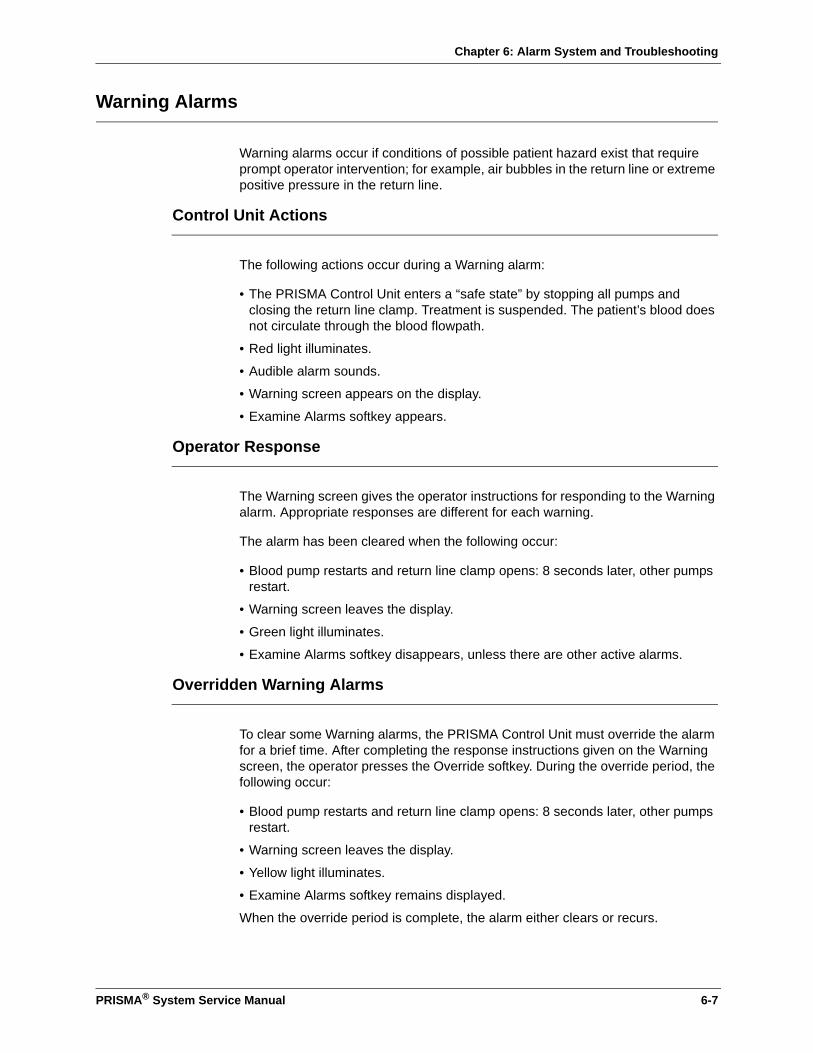
Chapter 6: Alarm System and Troubleshooting
Warning Alarms
Warning alarms occur if conditions of possible patient hazard exist that require prompt operator intervention; for example, air bubbles in the return line or extreme positive pressure in the return line.
Control Unit Actions
The following actions occur during a Warning alarm:
• The PRISMA Control Unit enters a “safe state” by stopping all pumps and closing the return line clamp. Treatment is suspended. The patient’s blood does not circulate through the blood flowpath.
• Red light illuminates.
• Audible alarm sounds.
• Warning screen appears on the display.
• Examine Alarms softkey appears.
Operator Response
The Warning screen gives the operator instructions for responding to the Warning alarm. Appropriate responses are different for each warning.
The alarm has been cleared when the following occur:
• Blood pump restarts and return line clamp opens: 8 seconds later, other pumps restart.
• Warning screen leaves the display.
• Green light illuminates.
• Examine Alarms softkey disappears, unless there are other active alarms.
Overridden Warning Alarms
To clear some Warning alarms, the PRISMA Control Unit must override the alarm for a brief time. After completing the response instructions given on the Warning screen, the operator presses the Override softkey. During the override period, the following occur:
• Blood pump restarts and return line clamp opens: 8 seconds later, other pumps restart.
• Warning screen leaves the display.
• Yellow light illuminates.
• Examine Alarms softkey remains displayed.
When the override period is complete, the alarm either clears or recurs.
PRISMA® System Service Manual 6-7

Chapter 6: Alarm System and Troubleshooting
Malfunction Alarms
Malfunction alarms occur if patient safety cannot be monitored due to a failure of the system; for example, failure during self-tests, errors in the software, or hardware failure.
Control Unit Actions
The following actions occur during a Malfunction alarm:
• The PRISMA Control Unit enters a “safe state” by stopping all pumps and closing the return line clamp. Treatment is suspended. The patient’s blood does not circulate through the blood flowpath.
• Red light illuminates.
• Audible alarm sounds.
• Malfunction screen appears on the display.
• Examine Alarms softkey appears.
Operator Response
Some malfunctions can be cleared by the operator; others require service by a trained and qualified technician. The Malfunction screen gives instructions for responding to the Malfunction alarm. Appropriate responses are different for each malfunction.
The alarm has been cleared when the following occur:
• Blood pump restarts and return line clamp opens. 8 seconds later, other pumps restart.
• Malfunction screen leaves the display.
• Green light illuminates.
• Examine Alarms softkey disappears, unless there are other active alarms.
If the operator cannot clear a particular Malfunction alarm, it must be cleared in Service mode by a trained and qualified technician. The Malfunction screen gives appropriate instructions, which include the following:
• End the patient’s treatment (with or without returning blood).
Note: If the Disconnect key is not available, the treatment can be terminated manually. Instructions for manual termination are given at the end of this chapter.
• Turn off the power.
• Call for service to repair the control unit and clear the alarm.
6-8 PRISMA® System Service Manual
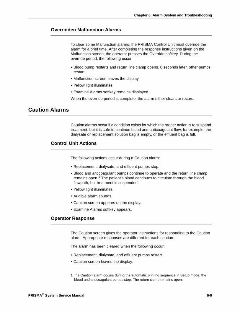
Chapter 6: Alarm System and Troubleshooting
Overridden Malfunction Alarms
To clear some Malfunction alarms, the PRISMA Control Unit must override the alarm for a brief time. After completing the response instructions given on the Malfunction screen, the operator presses the Override softkey. During the override period, the following occur:
• Blood pump restarts and return line clamp opens. 8 seconds later, other pumps restart.
• Malfunction screen leaves the display.
• Yellow light illuminates.
• Examine Alarms softkey remains displayed.
When the override period is complete, the alarm either clears or recurs.
Caution Alarms
Caution alarms occur if a condition exists for which the proper action is to suspend treatment, but it is safe to continue blood and anticoagulant flow; for example, the dialysate or replacement solution bag is empty, or the effluent bag is full.
Control Unit Actions
The following actions occur during a Caution alarm:
• Replacement, dialysate, and effluent pumps stop.
• Blood and anticoagulant pumps continue to operate and the return line clamp remains open.1 The patient’s blood continues to circulate through the blood flowpath, but treatment is suspended.
• Yellow light illuminates.
• Audible alarm sounds.
• Caution screen appears on the display.
• Examine Alarms softkey appears.
Operator Response
The Caution screen gives the operator instructions for responding to the Caution alarm. Appropriate responses are different for each caution.
The alarm has been cleared when the following occur:
• Replacement, dialysate, and effluent pumps restart.
• Caution screen leaves the display.
1. If a Caution alarm occurs during the automatic priming sequence in Setup mode, the blood and anticoagulant pumps stop. The return clamp remains open.
PRISMA® System Service Manual 6-9

Chapter 6: Alarm System and Troubleshooting
• Green light illuminates.
• Examine Alarms softkey disappears, unless there are other active alarms.
Advisory Alarms
Advisory alarms occur if a condition exists of which the operator should be aware, but the patient is not at immediate risk; for example, when preventive maintenance is due. The patient’s treatment continues during an Advisory alarm.
Control Unit Actions
The following actions occur during an Advisory alarm:
• No pumps stop; treatment continues.
• Yellow light illuminates.
• Audible alarm sounds.
• Advisory screen appears on the display.
• Examine Alarms softkey appears.
Operator Response
The “Time for Preventive Maintenance” Advisory alarm can only be cleared by a service technician; the other advisories can either be cleared or overridden by the operator; some advisories are also self-clearing.
The Advisory screen gives the operator instructions for responding to the Advisory alarm; appropriate responses are different for each advisory.
When an advisory has been cleared (self-cleared or cleared by the operator), the following occur:
• Advisory screen leaves the display.
• Green light illuminates.
• Examine Alarms softkey disappears, unless there are other active alarms.
Overridden Advisory Alarms
Many Advisory alarms can be overridden by the operator. If an Advisory alarm is overridden, it remains overridden indefinitely. If the overridden alarm is a self-clearing alarm, it clears when the condition no longer exists. If the overridden alarm is not self-clearing, it remains in a list of pending alarms. Pending alarms can be viewed by pressing the Examine Alarms softkey. See the “Alarm Priorities” section in this chapter for more information.
If the operator overrides an Advisory alarm, the following control unit actions occur:
6-10 PRISMA® System Service Manual
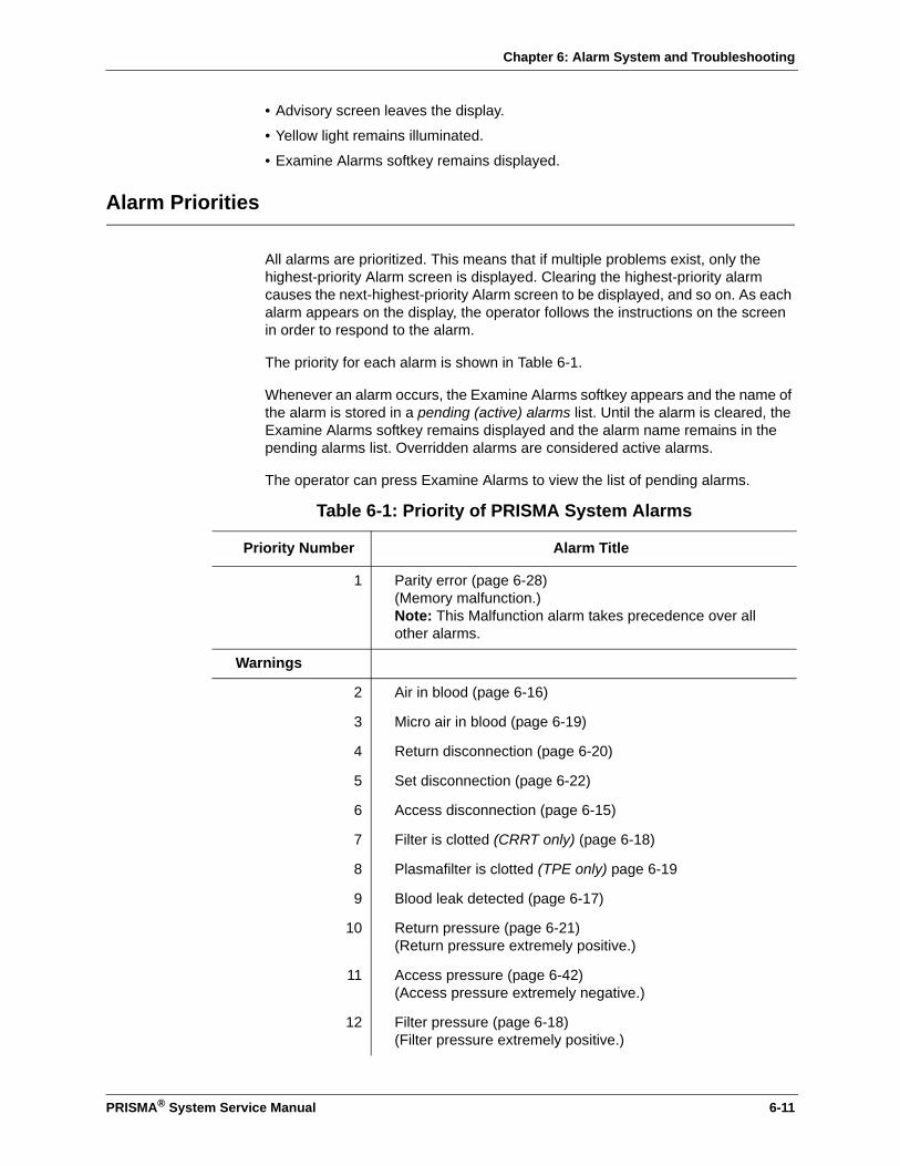
Chapter 6: Alarm System and Troubleshooting
• Advisory screen leaves the display.
• Yellow light remains illuminated.
• Examine Alarms softkey remains displayed.
Alarm Priorities
All alarms are prioritized. This means that if multiple problems exist, only the highest-priority Alarm screen is displayed. Clearing the highest-priority alarm causes the next-highest-priority Alarm screen to be displayed, and so on. As each alarm appears on the display, the operator follows the instructions on the screen in order to respond to the alarm.
The priority for each alarm is shown in Table 6-1.
Whenever an alarm occurs, the Examine Alarms softkey appears and the name of the alarm is stored in a pending (active) alarms list. Until the alarm is cleared, the Examine Alarms softkey remains displayed and the alarm name remains in the pending alarms list. Overridden alarms are considered active alarms.
The operator can press Examine Alarms to view the list of pending alarms.
Table 6-1: Priority of PRISMA System Alarms
Priority Number Alarm Title
1 Parity error (page 6-28)(Memory malfunction.)Note: This Malfunction alarm takes precedence over all other alarms.
Warnings
2 Air in blood (page 6-16)
3 Micro air in blood (page 6-19)
4 Return disconnection (page 6-20)
5 Set disconnection (page 6-22)
6 Access disconnection (page 6-15)
7 Filter is clotted (CRRT only) (page 6-18)
8 Plasmafilter is clotted (TPE only) page 6-19
9 Blood leak detected (page 6-17)
10 Return pressure (page 6-21)(Return pressure extremely positive.)
11 Access pressure (page 6-42)(Access pressure extremely negative.)
12 Filter pressure (page 6-18)(Filter pressure extremely positive.)
PRISMA® System Service Manual 6-11
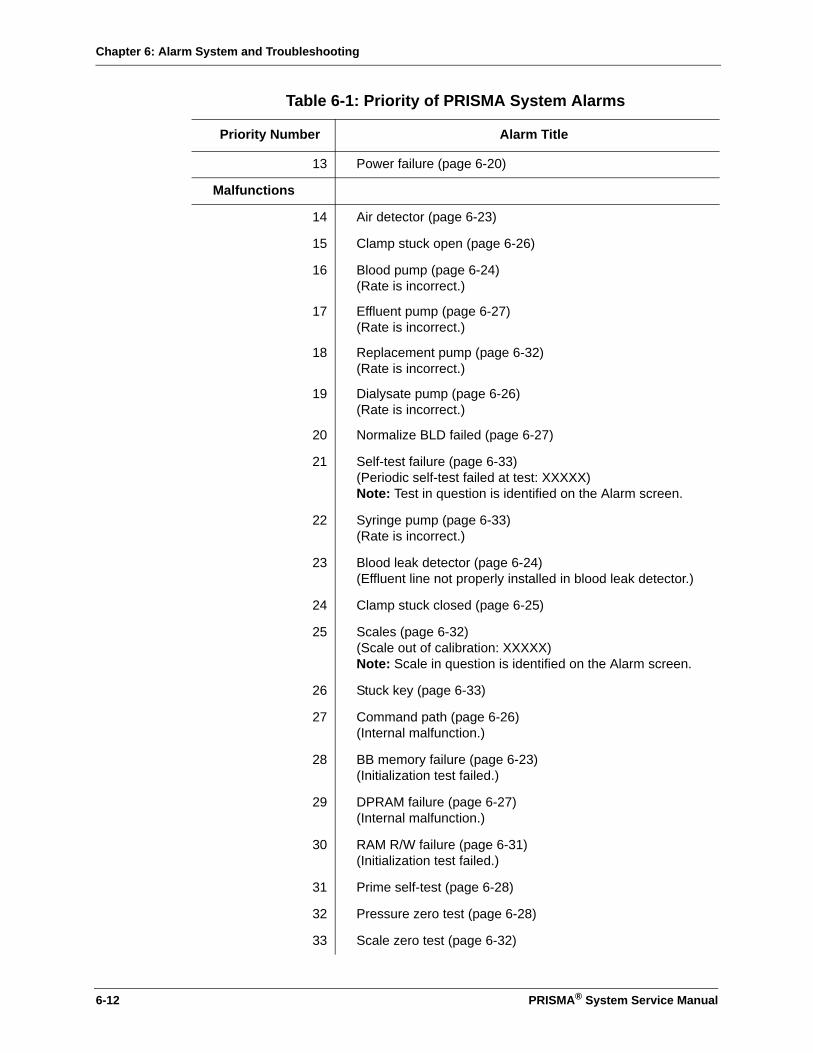
Chapter 6: Alarm System and Troubleshooting
13 Power failure (page 6-20)
Malfunctions
14 Air detector (page 6-23)
15 Clamp stuck open (page 6-26)
16 Blood pump (page 6-24)(Rate is incorrect.)
17 Effluent pump (page 6-27)(Rate is incorrect.)
18 Replacement pump (page 6-32)(Rate is incorrect.)
19 Dialysate pump (page 6-26)(Rate is incorrect.)
20 Normalize BLD failed (page 6-27)
21 Self-test failure (page 6-33)(Periodic self-test failed at test: XXXXX)Note: Test in question is identified on the Alarm screen.
22 Syringe pump (page 6-33)(Rate is incorrect.)
23 Blood leak detector (page 6-24)(Effluent line not properly installed in blood leak detector.)
24 Clamp stuck closed (page 6-25)
25 Scales (page 6-32)(Scale out of calibration: XXXXX)Note: Scale in question is identified on the Alarm screen.
26 Stuck key (page 6-33)
27 Command path (page 6-26)(Internal malfunction.)
28 BB memory failure (page 6-23)(Initialization test failed.)
29 DPRAM failure (page 6-27)(Internal malfunction.)
30 RAM R/W failure (page 6-31)(Initialization test failed.)
31 Prime self-test (page 6-28)
32 Pressure zero test (page 6-28)
33 Scale zero test (page 6-32)
Table 6-1: Priority of PRISMA System Alarms
Priority Number Alarm Title
6-12 PRISMA® System Service Manual

Chapter 6: Alarm System and Troubleshooting
34 Checksum interrupted (page 6-25)
Cautions
35 Excess Pt Fluid Loss or Gain
36 Effluent weight (page 6-37)(Incorrect weight change detected.)
37 Replacement weight (page 6-39)(Incorrect weight change detected.)
38 Dialysate weight (CRRT only) (page 6-35)(Incorrect weight change detected.)
39 TPE prescription delivered (TPE only) (page 6-41)(Prescribed replacement fluid input has been achieved.)
40 Effluent bag full (page 6-36)
41 Dialysate bag empty (CRRT only) (page 6-34)
42 Replacement bag empty (CRRT only) (page 6-38)
43 Replacement container empty (TPE only) (page 6-38)
44 Anticoag syringe empty (page 6-34)Note: This Caution is enabled only during priming (Setup mode). During a patient treatment (Run mode), the Advisory: Anticoag syringe empty alarm is enabled.
45 TMP excessive (CRRT only) (page 6-40)(Transmembrane pressure exceeds membrane pressure limit.)
46 TMPa excessive (TPE only) (page 6-40)(Access transmembrane pressure exceeds +100 mmHg.)
47 Effluent pressure (TPE only) (page 6-36)(Effluent pressure too negative.)
Advisories
48 Periodic self-test in progress (page 6-46)(Test complete in approximately 2 minutes.)
49 Return pressure (page 6-21)(Return pressure is dropping.)
50 Access pressure (page 6-42)(Access pressure is rising.)
51 Access too negative (page 6-43)
52 Return too positive (page 6-21)
Table 6-1: Priority of PRISMA System Alarms
Priority Number Alarm Title
PRISMA® System Service Manual 6-13
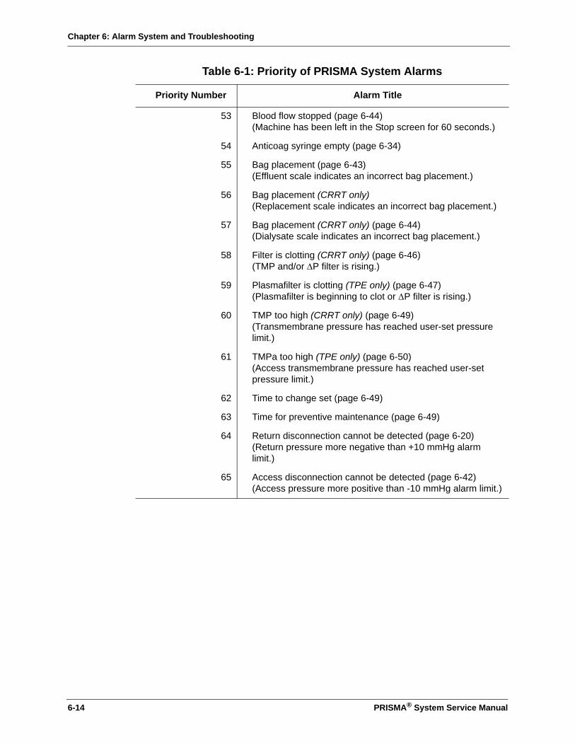
Chapter 6: Alarm System and Troubleshooting
53 Blood flow stopped (page 6-44)(Machine has been left in the Stop screen for 60 seconds.)
54 Anticoag syringe empty (page 6-34)
55 Bag placement (page 6-43)(Effluent scale indicates an incorrect bag placement.)
56 Bag placement (CRRT only)(Replacement scale indicates an incorrect bag placement.)
57 Bag placement (CRRT only) (page 6-44)(Dialysate scale indicates an incorrect bag placement.)
58 Filter is clotting (CRRT only) (page 6-46)(TMP and/or ∆P filter is rising.)
59 Plasmafilter is clotting (TPE only) (page 6-47)(Plasmafilter is beginning to clot or ∆P filter is rising.)
60 TMP too high (CRRT only) (page 6-49)(Transmembrane pressure has reached user-set pressure limit.)
61 TMPa too high (TPE only) (page 6-50)(Access transmembrane pressure has reached user-set pressure limit.)
62 Time to change set (page 6-49)
63 Time for preventive maintenance (page 6-49)
64 Return disconnection cannot be detected (page 6-20)(Return pressure more negative than +10 mmHg alarm limit.)
65 Access disconnection cannot be detected (page 6-42)(Access pressure more positive than -10 mmHg alarm limit.)
Table 6-1: Priority of PRISMA System Alarms
Priority Number Alarm Title
6-14 PRISMA® System Service Manual

Chapter 6: Alarm System and Troubleshooting
.
Table 6-2: Warning Alarms Troubleshooting
Observation Possible Cause(s) Operator Response
Access disconnection
Alarm occurs if access pressure is more positive than -10 mmHg and the access pressure operating point is more negative than -10 mmHg.
1. Access catheter disconnected; line is clamped below the access pressure pod.
2. Access pressure pod not installed or debris in access sensor housing.
3. Blood flow rate too low for the access device.
4. Access pressure sensor failed.
5. Clear segment of access line is disconnected or unclamped (TPE).
6. Saline infusion through clear segment of TPE access line.
1. Remedy; press Override.a
2. Perform Pod Diaphragm Reposition procedure on access pod (see instructions at end of this chapter); press Override.a
3. Increase the blood flow rate; return to Alarm screen and press Override.a
Note: If Steps 1, 2, and 3 do not clear the alarm, the set can be changed and the alarm cleared via the Stop key.b If alarm recurs with new set, see Step 4.4. End treatment via Stop.
See “Pressure Monitor Troubleshooting” on page 6-58.
5. Remedy; press Override.a
6. Press Overridea and monitor closely.
PRISMA® System Service Manual 6-15

Chapter 6: Alarm System and Troubleshooting
Access pressure (Access pressure extremely negative.)
Alarm occurs if access pressure is more negative than the user-settable “Access Pressure Extremely Negative” Warning Limit.
1. Access line clamped or kinked.
2. Access catheter clotted or out of position in vein.
3. Patient is moving or being moved.
4. Blood flow rate too high for the access device.
5. Access pressure sensor failed.
6. Red segment of TPE access line clamped.
1. Remedy; press Continue.2. Flush or reposition per
hospital protocol; press Continue.
3. Press Continue.
4. Lower the blood flow rate; return to Alarm screen and press Continue.
Note: If Steps 1 through 4 do not clear the alarm, the set can be changed and the alarm cleared via Stop.b If alarm recurs with new set, see Step 5.5. End treatment via Stop.
See “Pressure Monitor Troubleshooting” on page 6-58.
6. Remedy; press Override.a
Air in blood 1. Return line not installed in air detector.
2. Air bubble in line due to:-All therapies: Disconnected line, leaking connection, or incompletely primed set.-TPE therapy only: Disconnection of clear segment of access line, leaking connection, open, or incompletely primed clear segment of access line.
3. Air bubble detector failure.
1. Press return line into air detector; press Continue.
2. Remove air via instructions on Alarm screen. (Instructions also given under “Air Removal Procedures” at the end of this chapter.) Identify and remedy cause; press Continue.
Note: If air is prevalent in entire set, change the set via the Disconnect key.
3. See “Air Bubble Detector Troubleshooting” on page 6-61.
Table 6-2: Warning Alarms Troubleshooting (Continued)
Observation Possible Cause(s) Operator Response
6-16 PRISMA® System Service Manual

Chapter 6: Alarm System and Troubleshooting
Blood leak detected 1. Air bubble in effluent line at level of blood leak detector.
2. Effluent line not properly installed in blood leak detector.
3. Liquid or other debris in tubing path through the detector.
4. Leak in filter membrane.5. TPE therapy: formed
elements or lipids in plasma, discolored plasma.
6. Blood leak detector failure.
1. Dislodge bubble by giving the effluent pump a quick half-turn counterclockwise. Press Override.a
2. Press line into detector from the bottom up and route securely through tubing guides. Press Override.a
3. Remove line from detector. Using a “flossing” action, clean inside the detector with a lint-free cloth and isopropyl alcohol. Dry thoroughly. Clean effluent line with water and dry thoroughly. Reinsert line into detector and tubing guides. Press Override.a
Warning: If the effluent line is repositioned or removed/reinserted in detector, the detector must be reset by pressing Normalize BLD on the More Softkeys screen after the alarm clears. This must be done before continuing patient treatment. BLD signal value must be ≥150 for normalization to be allowed.4. Change the set via Stop.b5. Press Override.a Lower
replacement rate and/or patient plasma loss rate. Note: If this does not clear the alarm, the set can be changed via Stop. If alarm recurs with a new set and lowered flow rates, discontinue treatment.
6. See “Blood Leak Detector Alarm Troubleshooting” on page 6-66.
Table 6-2: Warning Alarms Troubleshooting (Continued)
Observation Possible Cause(s) Operator Response
PRISMA® System Service Manual 6-17
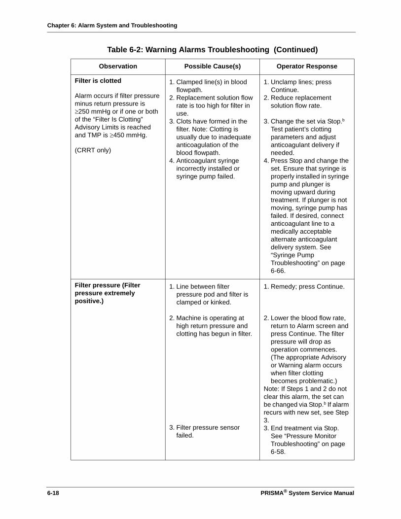
Chapter 6: Alarm System and Troubleshooting
Filter is clotted
Alarm occurs if filter pressure minus return pressure is ≥250 mmHg or if one or both of the “Filter Is Clotting” Advisory Limits is reached and TMP is ≥450 mmHg.
(CRRT only)
1. Clamped line(s) in blood flowpath.
2. Replacement solution flow rate is too high for filter in use.
3. Clots have formed in the filter. Note: Clotting is usually due to inadequate anticoagulation of the blood flowpath.
4. Anticoagulant syringe incorrectly installed or syringe pump failed.
1. Unclamp lines; press Continue.
2. Reduce replacement solution flow rate.
3. Change the set via Stop.b
Test patient’s clotting parameters and adjust anticoagulant delivery if needed.
4. Press Stop and change the set. Ensure that syringe is properly installed in syringe pump and plunger is moving upward during treatment. If plunger is not moving, syringe pump has failed. If desired, connect anticoagulant line to a medically acceptable alternate anticoagulant delivery system. See “Syringe Pump Troubleshooting” on page 6-66.
Filter pressure (Filter pressure extremely positive.)
1. Line between filter pressure pod and filter is clamped or kinked.
2. Machine is operating at high return pressure and clotting has begun in filter.
3. Filter pressure sensor failed.
1. Remedy; press Continue.
2. Lower the blood flow rate, return to Alarm screen and press Continue. The filter pressure will drop as operation commences. (The appropriate Advisory or Warning alarm occurs when filter clotting becomes problematic.)
Note: If Steps 1 and 2 do not clear this alarm, the set can be changed via Stop.b If alarm recurs with new set, see Step 3.3. End treatment via Stop.
See “Pressure Monitor Troubleshooting” on page 6-58.
Table 6-2: Warning Alarms Troubleshooting (Continued)
Observation Possible Cause(s) Operator Response
6-18 PRISMA® System Service Manual

Chapter 6: Alarm System and Troubleshooting
Micro air in blood 1. Leaking connection; set not fully primed.
2. Air bubble detector failure.
1. Remove micro air via instructions on Alarm screen. (Instructions also given under “Air Removal Procedures” at the end of this chapter.) Identify and remedy cause; press Override.a
Note: If air is prevalent in entire set, change the set via the Disconnect key.2. See “Air Bubble Detector
Troubleshooting” on page 6-61.
Plasmafilter is clotted
Alarm occurs if filter pressure minus return pressure is ≥100 mmHg more than it was when at the operating point.
(TPE only)
1. Clamped line(s) in blood flowpath.
2. Replacement fluid flow rate is too high for filter in use.
3. Clots have formed in the plasmafilter. Note: Clotting is usually due to inadequate anticoagulation of the blood flowpath.
4. Anticoagulant syringe incorrectly installed or syringe pump failed.
1. Unclamp lines; press Continue.
2. Reduce replacement fluid flow rate.
3. Change the set via Stop.b Test patient’s clotting parameters and adjust anticoagulant delivery if needed.
4. Press Stop and change the set. Ensure that syringe is properly installed in syringe pump and plunger is moving upward during treatment. If plunger is not moving, syringe pump has failed. If desired, connect anticoagulant line to a medically acceptable alternate anticoagulant delivery system. See “Syringe Pump Troubleshooting” on page 6-66. If all of the above steps fail, see “TMPa Troubleshooting” on page 6-74.
Table 6-2: Warning Alarms Troubleshooting (Continued)
Observation Possible Cause(s) Operator Response
PRISMA® System Service Manual 6-19
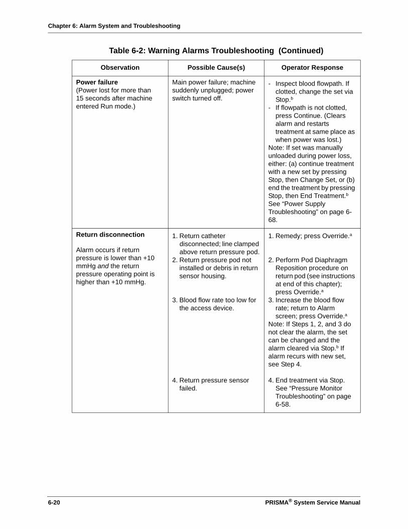
Chapter 6: Alarm System and Troubleshooting
Power failure(Power lost for more than 15 seconds after machine entered Run mode.)
Main power failure; machine suddenly unplugged; power switch turned off.
- Inspect blood flowpath. If clotted, change the set via Stop.b
- If flowpath is not clotted, press Continue. (Clears alarm and restarts treatment at same place as when power was lost.)
Note: If set was manually unloaded during power loss, either: (a) continue treatment with a new set by pressing Stop, then Change Set, or (b) end the treatment by pressing Stop, then End Treatment.bSee “Power Supply Troubleshooting” on page 6-68.
Return disconnection
Alarm occurs if return pressure is lower than +10 mmHg and the return pressure operating point is higher than +10 mmHg.
1. Return catheter disconnected; line clamped above return pressure pod.
2. Return pressure pod not installed or debris in return sensor housing.
3. Blood flow rate too low for the access device.
4. Return pressure sensor failed.
1. Remedy; press Override.a
2. Perform Pod Diaphragm Reposition procedure on return pod (see instructions at end of this chapter); press Override.a
3. Increase the blood flow rate; return to Alarm screen; press Override.a
Note: If Steps 1, 2, and 3 do not clear the alarm, the set can be changed and the alarm cleared via Stop.b If alarm recurs with new set, see Step 4.
4. End treatment via Stop. See “Pressure Monitor Troubleshooting” on page 6-58.
Table 6-2: Warning Alarms Troubleshooting (Continued)
Observation Possible Cause(s) Operator Response
6-20 PRISMA® System Service Manual
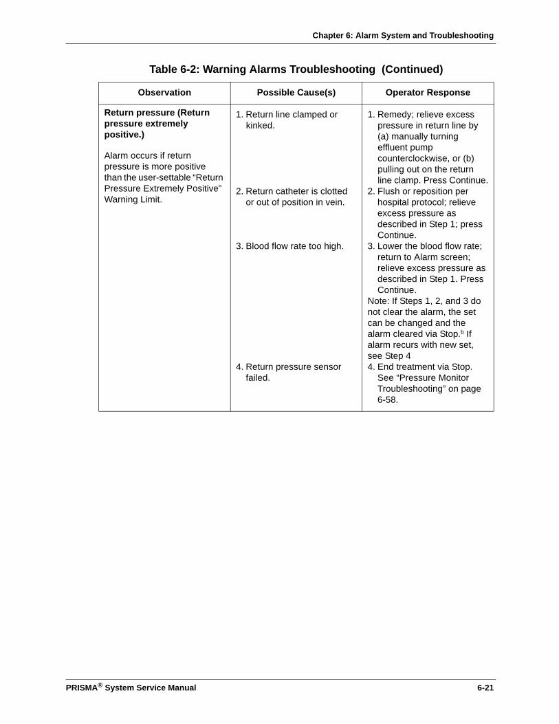
Chapter 6: Alarm System and Troubleshooting
Return pressure (Return pressure extremely positive.)
Alarm occurs if return pressure is more positive than the user-settable “Return Pressure Extremely Positive” Warning Limit.
1. Return line clamped or kinked.
2. Return catheter is clotted or out of position in vein.
3. Blood flow rate too high.
4. Return pressure sensor failed.
1. Remedy; relieve excess pressure in return line by (a) manually turning effluent pump counterclockwise, or (b) pulling out on the return line clamp. Press Continue.
2. Flush or reposition per hospital protocol; relieve excess pressure as described in Step 1; press Continue.
3. Lower the blood flow rate; return to Alarm screen; relieve excess pressure as described in Step 1. Press Continue.
Note: If Steps 1, 2, and 3 do not clear the alarm, the set can be changed and the alarm cleared via Stop.b If alarm recurs with new set, see Step 44. End treatment via Stop.
See “Pressure Monitor Troubleshooting” on page 6-58.
Table 6-2: Warning Alarms Troubleshooting (Continued)
Observation Possible Cause(s) Operator Response
PRISMA® System Service Manual 6-21
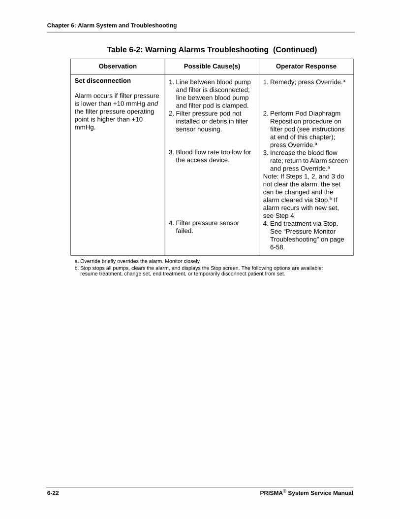
Chapter 6: Alarm System and Troubleshooting
Set disconnection
Alarm occurs if filter pressure is lower than +10 mmHg and the filter pressure operating point is higher than +10 mmHg.
1. Line between blood pump and filter is disconnected; line between blood pump and filter pod is clamped.
2. Filter pressure pod not installed or debris in filter sensor housing.
3. Blood flow rate too low for the access device.
4. Filter pressure sensor failed.
1. Remedy; press Override.a
2. Perform Pod Diaphragm Reposition procedure on filter pod (see instructions at end of this chapter); press Override.a
3. Increase the blood flow rate; return to Alarm screen and press Override.a
Note: If Steps 1, 2, and 3 do not clear the alarm, the set can be changed and the alarm cleared via Stop.b If alarm recurs with new set, see Step 4.4. End treatment via Stop.
See “Pressure Monitor Troubleshooting” on page 6-58.
a. Override briefly overrides the alarm. Monitor closely.b. Stop stops all pumps, clears the alarm, and displays the Stop screen. The following options are available:
resume treatment, change set, end treatment, or temporarily disconnect patient from set.
Table 6-2: Warning Alarms Troubleshooting (Continued)
Observation Possible Cause(s) Operator Response
6-22 PRISMA® System Service Manual
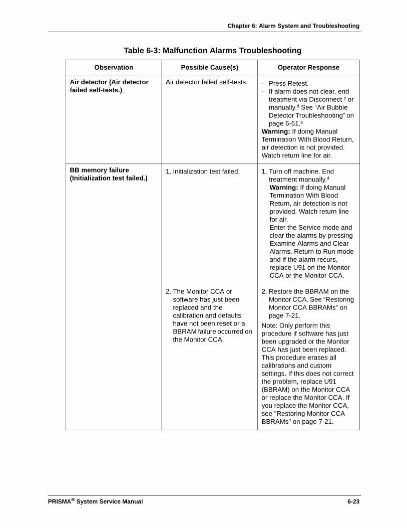
Chapter 6: Alarm System and Troubleshooting
Table 6-3: Malfunction Alarms Troubleshooting
Observation Possible Cause(s) Operator Response
Air detector (Air detector failed self-tests.)
Air detector failed self-tests. - Press Retest.- If alarm does not clear, end
treatment via Disconnect c or manually.d See “Air Bubble Detector Troubleshooting” on page 6-61.a
Warning: If doing Manual Termination With Blood Return, air detection is not provided. Watch return line for air.
BB memory failure (Initialization test failed.)
1. Initialization test failed.
2. The Monitor CCA or software has just been replaced and the calibration and defaults have not been reset or a BBRAM failure occurred on the Monitor CCA.
1. Turn off machine. End treatment manually.d Warning: If doing Manual Termination With Blood Return, air detection is not provided. Watch return line for air.Enter the Service mode and clear the alarms by pressing Examine Alarms and Clear Alarms. Return to Run mode and if the alarm recurs, replace U91 on the Monitor CCA or the Monitor CCA.
2. Restore the BBRAM on the Monitor CCA. See “Restoring Monitor CCA BBRAMs” on page 7-21.
Note: Only perform this procedure if software has just been upgraded or the Monitor CCA has just been replaced. This procedure erases all calibrations and custom settings. If this does not correct the problem, replace U91 (BBRAM) on the Monitor CCA or replace the Monitor CCA. If you replace the Monitor CCA, see "Restoring Monitor CCA BBRAMs" on page 7-21.
PRISMA® System Service Manual 6-23
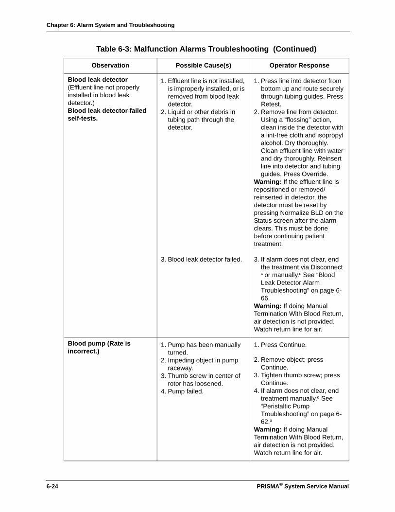
Chapter 6: Alarm System and Troubleshooting
Blood leak detector(Effluent line not properly installed in blood leak detector.)Blood leak detector failed self-tests.
1. Effluent line is not installed, is improperly installed, or is removed from blood leak detector.
2. Liquid or other debris in tubing path through the detector.
3. Blood leak detector failed.
1. Press line into detector from bottom up and route securely through tubing guides. Press Retest.
2. Remove line from detector. Using a “flossing” action, clean inside the detector with a lint-free cloth and isopropyl alcohol. Dry thoroughly. Clean effluent line with water and dry thoroughly. Reinsert line into detector and tubing guides. Press Override.
Warning: If the effluent line is repositioned or removed/reinserted in detector, the detector must be reset by pressing Normalize BLD on the Status screen after the alarm clears. This must be done before continuing patient treatment.
3. If alarm does not clear, end the treatment via Disconnect c or manually.d See “Blood Leak Detector Alarm Troubleshooting” on page 6-66.
Warning: If doing Manual Termination With Blood Return, air detection is not provided. Watch return line for air.
Blood pump (Rate is incorrect.)
1. Pump has been manually turned.
2. Impeding object in pump raceway.
3. Thumb screw in center of rotor has loosened.
4. Pump failed.
1. Press Continue.
2. Remove object; press Continue.
3. Tighten thumb screw; press Continue.
4. If alarm does not clear, end treatment manually.d See “Peristaltic Pump Troubleshooting” on page 6-62.a
Warning: If doing Manual Termination With Blood Return, air detection is not provided. Watch return line for air.
Table 6-3: Malfunction Alarms Troubleshooting (Continued)
Observation Possible Cause(s) Operator Response
6-24 PRISMA® System Service Manual
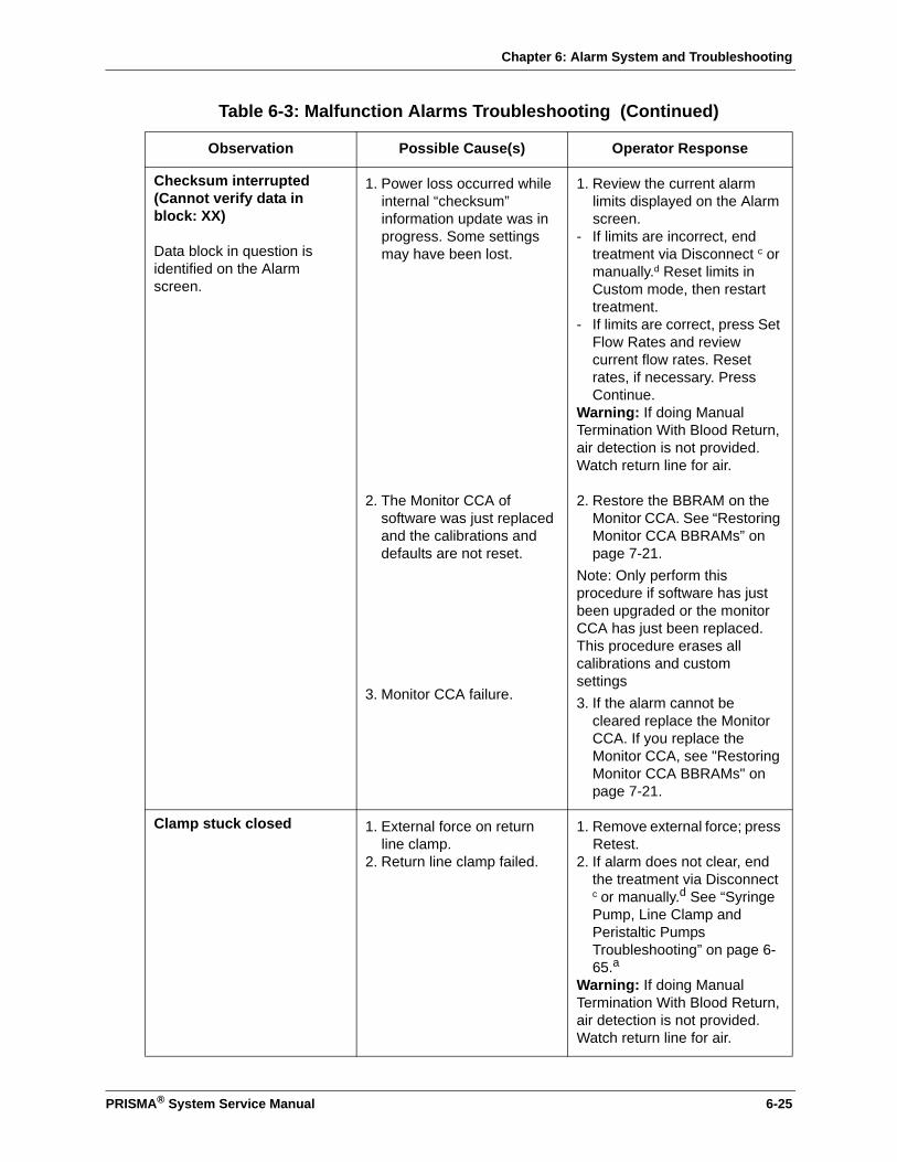
Chapter 6: Alarm System and Troubleshooting
Checksum interrupted (Cannot verify data in block: XX)
Data block in question is identified on the Alarm screen.
1. Power loss occurred while internal “checksum” information update was in progress. Some settings may have been lost.
2. The Monitor CCA of software was just replaced and the calibrations and defaults are not reset.
3. Monitor CCA failure.
1. Review the current alarm limits displayed on the Alarm screen.
- If limits are incorrect, end treatment via Disconnect c or manually.d Reset limits in Custom mode, then restart treatment.
- If limits are correct, press Set Flow Rates and review current flow rates. Reset rates, if necessary. Press Continue.
Warning: If doing Manual Termination With Blood Return, air detection is not provided. Watch return line for air.
2. Restore the BBRAM on the Monitor CCA. See “Restoring Monitor CCA BBRAMs” on page 7-21.
Note: Only perform this procedure if software has just been upgraded or the monitor CCA has just been replaced. This procedure erases all calibrations and custom settings3. If the alarm cannot be
cleared replace the Monitor CCA. If you replace the Monitor CCA, see "Restoring Monitor CCA BBRAMs" on page 7-21.
Clamp stuck closed 1. External force on return line clamp.
2. Return line clamp failed.
1. Remove external force; press Retest.
2. If alarm does not clear, end the treatment via Disconnect c or manually.d See “Syringe Pump, Line Clamp and Peristaltic Pumps Troubleshooting” on page 6-65.a
Warning: If doing Manual Termination With Blood Return, air detection is not provided. Watch return line for air.
Table 6-3: Malfunction Alarms Troubleshooting (Continued)
Observation Possible Cause(s) Operator Response
PRISMA® System Service Manual 6-25
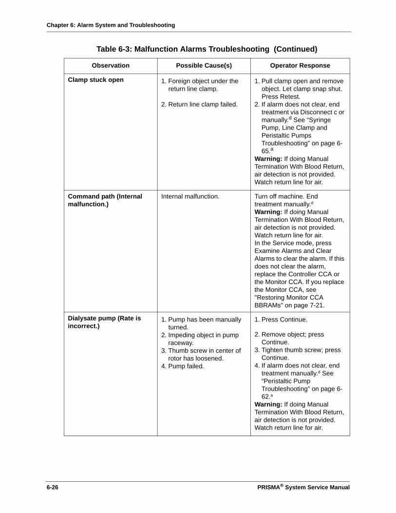
Chapter 6: Alarm System and Troubleshooting
Clamp stuck open 1. Foreign object under the return line clamp.
2. Return line clamp failed.
1. Pull clamp open and remove object. Let clamp snap shut. Press Retest.
2. If alarm does not clear, end treatment via Disconnect c or manually.d See “Syringe Pump, Line Clamp and Peristaltic Pumps Troubleshooting” on page 6-65.a
Warning: If doing Manual Termination With Blood Return, air detection is not provided. Watch return line for air.
Command path (Internal malfunction.)
Internal malfunction. Turn off machine. End treatment manually.d Warning: If doing Manual Termination With Blood Return, air detection is not provided. Watch return line for air.In the Service mode, press Examine Alarms and Clear Alarms to clear the alarm. If this does not clear the alarm, replace the Controller CCA or the Monitor CCA. If you replace the Monitor CCA, see "Restoring Monitor CCA BBRAMs" on page 7-21.
Dialysate pump (Rate is incorrect.)
1. Pump has been manually turned.
2. Impeding object in pump raceway.
3. Thumb screw in center of rotor has loosened.
4. Pump failed.
1. Press Continue.
2. Remove object; press Continue.
3. Tighten thumb screw; press Continue.
4. If alarm does not clear, end treatment manually.d See “Peristaltic Pump Troubleshooting” on page 6-62.a
Warning: If doing Manual Termination With Blood Return, air detection is not provided. Watch return line for air.
Table 6-3: Malfunction Alarms Troubleshooting (Continued)
Observation Possible Cause(s) Operator Response
6-26 PRISMA® System Service Manual
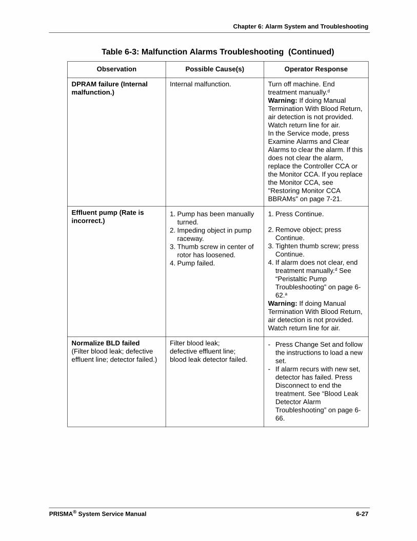
Chapter 6: Alarm System and Troubleshooting
DPRAM failure (Internal malfunction.)
Internal malfunction. Turn off machine. End treatment manually.d Warning: If doing Manual Termination With Blood Return, air detection is not provided. Watch return line for air.In the Service mode, press Examine Alarms and Clear Alarms to clear the alarm. If this does not clear the alarm, replace the Controller CCA or the Monitor CCA. If you replace the Monitor CCA, see "Restoring Monitor CCA BBRAMs" on page 7-21.
Effluent pump (Rate is incorrect.)
1. Pump has been manually turned.
2. Impeding object in pump raceway.
3. Thumb screw in center of rotor has loosened.
4. Pump failed.
1. Press Continue.
2. Remove object; press Continue.
3. Tighten thumb screw; press Continue.
4. If alarm does not clear, end treatment manually.d See “Peristaltic Pump Troubleshooting” on page 6-62.a
Warning: If doing Manual Termination With Blood Return, air detection is not provided. Watch return line for air.
Normalize BLD failed(Filter blood leak; defective effluent line; detector failed.)
Filter blood leak; defective effluent line; blood leak detector failed.
- Press Change Set and follow the instructions to load a new set.
- If alarm recurs with new set, detector has failed. Press Disconnect to end the treatment. See “Blood Leak Detector Alarm Troubleshooting” on page 6-66.
Table 6-3: Malfunction Alarms Troubleshooting (Continued)
Observation Possible Cause(s) Operator Response
PRISMA® System Service Manual 6-27
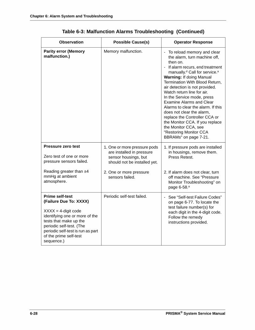
Chapter 6: Alarm System and Troubleshooting
Parity error (Memory malfunction.)
Memory malfunction. - To reload memory and clear the alarm, turn machine off, then on.
- If alarm recurs, end treatment manually.d Call for service.a
Warning: If doing Manual Termination With Blood Return, air detection is not provided. Watch return line for air.In the Service mode, press Examine Alarms and Clear Alarms to clear the alarm. If this does not clear the alarm, replace the Controller CCA or the Monitor CCA. If you replace the Monitor CCA, see "Restoring Monitor CCA BBRAMs" on page 7-21.
Pressure zero test
Zero test of one or more pressure sensors failed.
Reading greater than ±4 mmHg at ambient atmosphere.
1. One or more pressure pods are installed in pressure sensor housings, but should not be installed yet.
2. One or more pressure sensors failed.
1. If pressure pods are installed in housings, remove them. Press Retest.
2. If alarm does not clear, turn off machine. See “Pressure Monitor Troubleshooting” on page 6-58.a
Prime self-test(Failure Due To: XXXX)
XXXX = 4-digit code identifying one or more of the tests that make up the periodic self-test. (The periodic self-test is run as part of the prime self-test sequence.)
Periodic self-test failed. - See “Self-test Failure Codes” on page 6-77. To locate the test failure number(s) for each digit in the 4-digit code. Follow the remedy instructions provided.
Table 6-3: Malfunction Alarms Troubleshooting (Continued)
Observation Possible Cause(s) Operator Response
6-28 PRISMA® System Service Manual

Chapter 6: Alarm System and Troubleshooting
(Failure Due To: Blood Leak Detector Normalization OR Blood Leak Detector Threshold)
(continued on next page)
1. Effluent line not correctly installed in blood leak detector.
2. Air bubble in effluent line at level of blood leak detector.
3. Set not fully primed.
4. Blood leak detector failed.
(continued on next page)
1. Remove effluent line from detector and reinstall. Press Retest.
2. Dislodge bubble by giving the effluent pump a quick half-turn counterclockwise. Press Retest.
3. Hang new 1-L bag of priming solution and connect return line to it. Connect access line to an empty collection bag. Press Reprime.
Note: If Steps1, 2, and 3 do not clear the alarm, the set can be unloaded and alarm cleared via Unload. If alarm recurs with same “Failure Due To: Blood Leak Detector Normalization or Threshold” message, see Step 4.
4. Unload set. See “Blood Leak Detector Alarm Troubleshooting” on page 6-66.
(continued on next page)
Table 6-3: Malfunction Alarms Troubleshooting (Continued)
Observation Possible Cause(s) Operator Response
PRISMA® System Service Manual 6-29

Chapter 6: Alarm System and Troubleshooting
Prime self-test (continued)(Failure Due To: PRISMA Set Recognition Test Failed)
(continued on next page)
(continued)1. Set loaded is the wrong
type for the selected therapy.
2. Dialysate line is clamped.
3. Effluent pressure pod or dialysate pump segment not installed.
4. Effluent pressure pod failed due to kinked line(s) in the set.
5. Priming solution bag empty
(continued on next page)
(continued)1. Unload set and clear alarm
via Unload. (Control Unit proceeds to Disconnect Patient, then Treatment Complete.) Obtain the proper set for the selected therapy and start over.
Note: Use a PRISMA Set for CRRT with SCUF, CVVH, CVVHD, and CVVHDF therapies. Use a PRISMA TPE Set with TPE therapy.2. Unclamp dialysate line,
identify problem and remedy; press Retest.
3. Identify problem and remedy; press Retest.
Note: To install the dialysate pump segment, manually turn pump until segment works itself into raceway.4. Ensure there are no kinks or
occlusions in the lines of the set; press Retest.
Note: If alarm recurs due to this cause, it may be necessary to do the Diaphragm Reposition procedure on the effluent pod before pressing Retest. (See instructions at end of this chapter.)
5. Hang new 1-liter bag of priming solution and connect return line to it. Connect access line to an empty collection bag, if necessary. Press Reprime.
Note: If alarm recurs after doing Steps 1 through 5, see Step 6.
(continued on next page)
Table 6-3: Malfunction Alarms Troubleshooting (Continued)
Observation Possible Cause(s) Operator Response
6-30 PRISMA® System Service Manual

Chapter 6: Alarm System and Troubleshooting
Prime self-test (continued)(Failure Due To: PRISMA Set Recognition Test Failed)
(continued)6. Filter port(s) leaking.Note: The PRISMA set for CRRT has two filter ports which connect the fluid compartment of the filter to the dialysate and effluent lines of the set.7. Effluent pressure sensor
(internal) failed.
8. Dialysate pump failed.
(continued)6. Tighten luer connections.
Press Retest. If leaking does not stop, follow directions in Step 1 to unload set and start again with new set.
7. Unload set. See “Pressure Monitor Troubleshooting” on page 6-58.
8. See “Peristaltic Pump Troubleshooting” on page 6-62.
Prime Self-test (Failure Due To: TMPa calibration failed.)
1. Filter, effluent, or return pressure pod not installed; debris in filter, effluent, or return sensor housing.
2. Filter, effluent, or return pressure sensor failed.
3. ARPS failed.
1. Do Diaphragm Reposition procedure on any uninstalled pod (see instructions at the end of this chapter). Install and press Retest.If all pods are installed, do Reposition procedure on filter, effluent, and return pods to remove possible debris. Install and press Retest.
2. Unload set. See “TMPa Troubleshooting” on page 6-74.
3. See “Repositioning System Troubleshooting” on page 6-71.
RAM R/W failure (Initialization test failed.)
All lights are illuminated with this alarm.
Initialization test failed. - To reload memory and clear the alarm, turn machine off, then on.
- If alarm recurs, end treatment manually.d Call for service.a
Warning: If doing Manual Termination With Blood Return, air detection is not provided. Watch return line for air.In the Service mode, press Examine Alarms and Clear Alarms to clear the alarm. If this does not clear the alarm, replace the Controller CCA or the Monitor CCA. If you replace the Monitor CCA, see "Restoring Monitor CCA BBRAMs" on page 7-21.
Table 6-3: Malfunction Alarms Troubleshooting (Continued)
Observation Possible Cause(s) Operator Response
PRISMA® System Service Manual 6-31

Chapter 6: Alarm System and Troubleshooting
Replacement pump(Rate is incorrect.)
1. Pump has been manually turned.
2. Impeding object in pump raceway.
3. Thumb screw in center of rotor has loosened.
4. Pump failed.
1. Press Continue.
2. Remove object; press Continue.
3. Tighten thumb screw; press Continue.
4. If alarm does not clear, end treatment manually.d See “Peristaltic Pump Troubleshooting” on page 6-62.a
Warning: If doing Manual Termination With Blood Return, air detection is not provided. Watch return line for air.
Scales (Scale out of calibration: XXXX)
Scale in question is specified on the Alarm screen.
1. Specified scale is out of calibration.
2. Room temperature variations are greater than ±3 oC (5.4 oF) from the temperature at which the scales were calibrated.
3. Scale failure.
1. Press Retest. If alarm does not clear, end treatment via Disconnect c or manually.d Recalibrate the scale in question.a
Warning: If doing Manual Termination With Blood Return, air detection is not provided. Watch return line for air.
2. Calibrate the scales in an average room temperature. Also, make sure that the control unit is not in front of a heater, in direct sunlight or, in front of a cooling vent.
3. See “Scale Troubleshooting” on page 6-54.
Scale zero test
Zero test of one or more scales failed.
1. Foreign objects are touching scales or hanging from scale hooks.
2. Room temperature variations are greater than ±3 oC (5.4 oF) from the temperature at which the scales were calibrated.
3. One or more scales failed.
1. Make sure nothing is touching scales and no foreign objects are on scale hooks. Press Retest.
2. Calibrate the scales in an average room temperature. Also, make sure that the control unit is not in front of a heater, in direct sunlight or, in front of a cooling vent.
3. See “Scale Troubleshooting” on page 6-54.
Table 6-3: Malfunction Alarms Troubleshooting (Continued)
Observation Possible Cause(s) Operator Response
6-32 PRISMA® System Service Manual
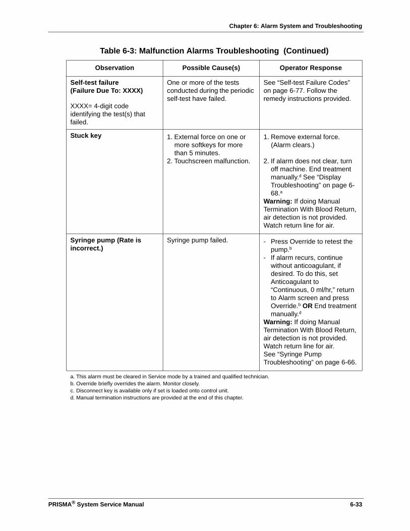
Chapter 6: Alarm System and Troubleshooting
Self-test failure(Failure Due To: XXXX)
XXXX= 4-digit code identifying the test(s) that failed.
One or more of the tests conducted during the periodic self-test have failed.
See “Self-test Failure Codes” on page 6-77. Follow the remedy instructions provided.
Stuck key 1. External force on one or more softkeys for more than 5 minutes.
2. Touchscreen malfunction.
1. Remove external force. (Alarm clears.)
2. If alarm does not clear, turn off machine. End treatment manually.d See “Display Troubleshooting” on page 6-68.a
Warning: If doing Manual Termination With Blood Return, air detection is not provided. Watch return line for air.
Syringe pump (Rate is incorrect.)
Syringe pump failed. - Press Override to retest the pump.b
- If alarm recurs, continue without anticoagulant, if desired. To do this, set Anticoagulant to “Continuous, 0 ml/hr,” return to Alarm screen and press Override.b OR End treatment manually.d
Warning: If doing Manual Termination With Blood Return, air detection is not provided. Watch return line for air.See “Syringe Pump Troubleshooting” on page 6-66.
a. This alarm must be cleared in Service mode by a trained and qualified technician.b. Override briefly overrides the alarm. Monitor closely.c. Disconnect key is available only if set is loaded onto control unit.d. Manual termination instructions are provided at the end of this chapter.
Table 6-3: Malfunction Alarms Troubleshooting (Continued)
Observation Possible Cause(s) Operator Response
PRISMA® System Service Manual 6-33
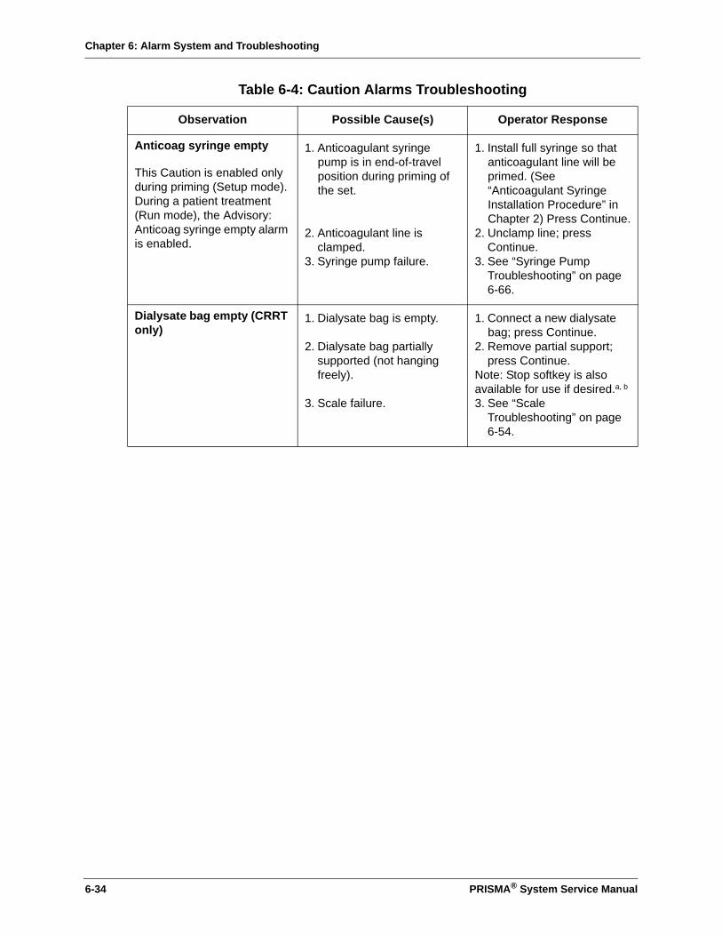
Chapter 6: Alarm System and Troubleshooting
Table 6-4: Caution Alarms Troubleshooting
Observation Possible Cause(s) Operator Response
Anticoag syringe empty
This Caution is enabled only during priming (Setup mode). During a patient treatment (Run mode), the Advisory: Anticoag syringe empty alarm is enabled.
1. Anticoagulant syringe pump is in end-of-travel position during priming of the set.
2. Anticoagulant line is clamped.
3. Syringe pump failure.
1. Install full syringe so that anticoagulant line will be primed. (See “Anticoagulant Syringe Installation Procedure” in Chapter 2) Press Continue.
2. Unclamp line; press Continue.
3. See “Syringe Pump Troubleshooting” on page 6-66.
Dialysate bag empty (CRRT only)
1. Dialysate bag is empty.
2. Dialysate bag partially supported (not hanging freely).
3. Scale failure.
1. Connect a new dialysate bag; press Continue.
2. Remove partial support; press Continue.
Note: Stop softkey is also available for use if desired.a, b
3. See “Scale Troubleshooting” on page 6-54.
6-34 PRISMA® System Service Manual

Chapter 6: Alarm System and Troubleshooting
Dialysate weight (Incorrect weight change detected.)
(CRRT only)
1. Dialysate bag frangible pin(s) is not completely broken.
2. Kinked or clamped dialysate line.
3. Bag is swinging on scale hook.
4. Leaking of dialysate line or bag, lines not properly connected.
5. Foreign object on dialysate scale.
6. Dialysate bag partially supported (not hanging freely).
7. Cartridge of the PRISMA Set is dislodged from cartridge carrier.
8. Room temperature variations are greater than ±3 oC (5.4 oF) from the temperature at which the scales were calibrated.
9. Dialysate scale failed; internal malfunction.
1. Using aseptic technique, manipulate bag fangible pin(s) to provide unobstructed fluid pathway.Check for unpartially broken pin, Press CONTINUE.
2. Unclamp line. Verify that line is free of kinks, Press CONTINUE.
3. Manually stabilize the bag, Press CONTINUE.
4. Using aseptic technique, manipulate lines and connections to correct leakage, Press CONTINUE.
5. Remove object; Press CONTINUE.
6. Remove partial support; Press CONTINUE.
7. If the pump segments are correctly inserted in the pump raceways, press cartridge into cartridge carrier; press CONTINUE. Otherwise, press STOP and change set.
Note: STOP softkey is available for use in above steps, if desired.a8. Calibrate the scales in an
average room temperature. Also, make sure that the control unit is not in front of a heater, in direct sunlight or, in front of a cooling vent.
9. Press STOP and end the treatment. Calibrate the scales in an average room temperature. Also, make sure that the control unit is not in front of a heater, in direct sunlight or, in front of a cooling vent.
Table 6-4: Caution Alarms Troubleshooting (Continued)
Observation Possible Cause(s) Operator Response
PRISMA® System Service Manual 6-35
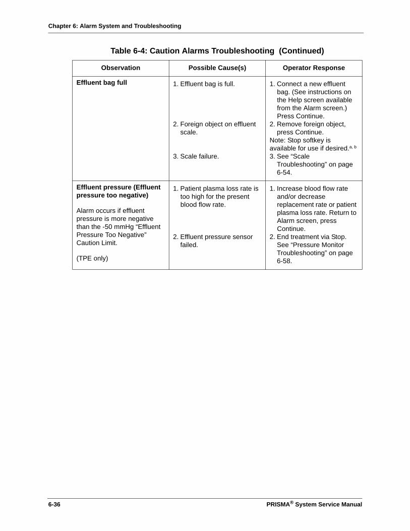
Chapter 6: Alarm System and Troubleshooting
Effluent bag full 1. Effluent bag is full.
2. Foreign object on effluent scale.
3. Scale failure.
1. Connect a new effluent bag. (See instructions on the Help screen available from the Alarm screen.) Press Continue.
2. Remove foreign object, press Continue.
Note: Stop softkey is available for use if desired.a, b
3. See “Scale Troubleshooting” on page 6-54.
Effluent pressure (Effluent pressure too negative)
Alarm occurs if effluent pressure is more negative than the -50 mmHg “Effluent Pressure Too Negative” Caution Limit.
(TPE only)
1. Patient plasma loss rate is too high for the present blood flow rate.
2. Effluent pressure sensor failed.
1. Increase blood flow rate and/or decrease replacement rate or patient plasma loss rate. Return to Alarm screen, press Continue.
2. End treatment via Stop. See “Pressure Monitor Troubleshooting” on page 6-58.
Table 6-4: Caution Alarms Troubleshooting (Continued)
Observation Possible Cause(s) Operator Response
6-36 PRISMA® System Service Manual

Chapter 6: Alarm System and Troubleshooting
Effluent weight (Incorrect weight change detected.)
1. Kinked or clamped Effluent line.
2. Bag is swinging on scale hook.
3. Leaking of effluent line or bag, lines not properly connected.
4. Foreign object on effuent scale.
5. Effluent bag partially supported (not hanging freely).
6. Cartridge of the PRISMA Set is dislodged from cartridge carrier.
7. Room temperature variations are greater than ±3 oC (5.4 oF) from the temperature at which the scales were calibrated.
8. Effluent scale failed; internal malfunction.
1. Unclamp line. Verify that line is free of kinks.
2. Manually stabilize the bag, Press CONTINUE.
3. Using aseptic technique, manipulate lines and connections to correct leakage.
4. Remove object; press CONTINUE.
5. Remove partial support; press CONTINUE.
6. If the pump segments are correctly inserted in the pump raceways, press cartridge into cartridge carrier; press CONTINUE. Otherwise, press STOP and change set.
Note: STOP softkey is available for use in above steps, if desired.a
7. Calibrate the scales in an average room temperature. Also, make sure that the control unit is not in front of a heater, in direct sunlight or, in front of a cooling vent.
8. Press STOP and end the treatment. Calibrate the scales in an average room temperature. Also, make sure that the control unit is not in front of a heater, in direct sunlight or, in front of a cooling vent.
Table 6-4: Caution Alarms Troubleshooting (Continued)
Observation Possible Cause(s) Operator Response
PRISMA® System Service Manual 6-37
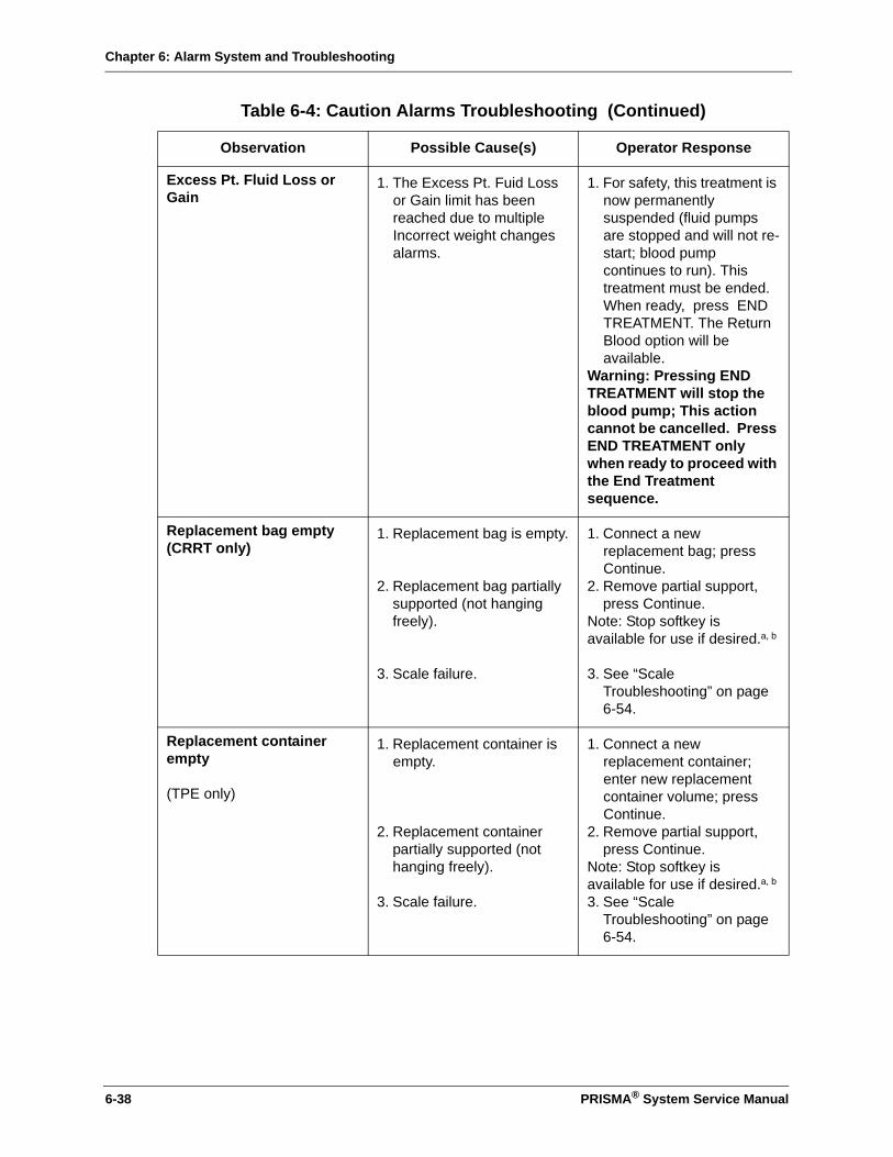
Chapter 6: Alarm System and Troubleshooting
Excess Pt. Fluid Loss or Gain
1. The Excess Pt. Fuid Loss or Gain limit has been reached due to multiple Incorrect weight changes alarms.
1. For safety, this treatment is now permanently suspended (fluid pumps are stopped and will not re-start; blood pump continues to run). This treatment must be ended. When ready, press END TREATMENT. The Return Blood option will be available.
Warning: Pressing END TREATMENT will stop the blood pump; This action cannot be cancelled. Press END TREATMENT only when ready to proceed with the End Treatment sequence.
Replacement bag empty (CRRT only)
1. Replacement bag is empty.
2. Replacement bag partially supported (not hanging freely).
3. Scale failure.
1. Connect a new replacement bag; press Continue.
2. Remove partial support, press Continue.
Note: Stop softkey is available for use if desired.a, b
3. See “Scale Troubleshooting” on page 6-54.
Replacement container empty
(TPE only)
1. Replacement container is empty.
2. Replacement container partially supported (not hanging freely).
3. Scale failure.
1. Connect a new replacement container; enter new replacement container volume; press Continue.
2. Remove partial support, press Continue.
Note: Stop softkey is available for use if desired.a, b
3. See “Scale Troubleshooting” on page 6-54.
Table 6-4: Caution Alarms Troubleshooting (Continued)
Observation Possible Cause(s) Operator Response
6-38 PRISMA® System Service Manual

Chapter 6: Alarm System and Troubleshooting
Replacement weight (Incorrect weight change detected.)
1. Replacement bag/container frangible pin(s) is not completely broken.
2. Kinked or clamped replacement bag/container line.
3. Bag is swinging on scale hook.
4. Leaking of replacement bag/ container line or bag, lines not properly connected.
5. Foreign object on replacement scale.
6. Replacement bag/container partially supported (not hanging freely).
7. Cartridge of the PRISMA Set is dislodged from cartridge carrier.
8. Room temperature variations are greater than ±3 oC (5.4 oF) from the temperature at which the scales were calibrated.
9. Replacement scale failed; internal malfunction.
1. Using aseptic technique, manipulate bag frangible pin(s) to provide unobstructed fluid pathway.Check for partially broken pin(s).
2. Unclamp line. Verify that line is free of kinks.
3. Manually stabilize the bag, Press CONTINUE.
4. Using aseptic technique, manipulate lines and connections to correct leakage.
5. Remove object; press CONTINUE.
6. Remove partial support; press CONTINUE.
7. If the pump segments are correctly inserted in the pump raceways, press cartridge into cartridge carrier; press CONTINUE. Otherwise, press STOP and change set.
Note: STOP softkey is available for use in above steps, if desired.a8. Calibrate the scales in an
average room temperature. Also, make sure that the control unit is not in front of a heater, in direct sunlight or, in front of a cooling vent.
9. Press STOP and end the treatment. Calibrate the scales in an average room temperature. Also, make sure that the control unit is not in front of a heater, in direct sunlight or, in front of a cooling vent.
Table 6-4: Caution Alarms Troubleshooting (Continued)
Observation Possible Cause(s) Operator Response
PRISMA® System Service Manual 6-39
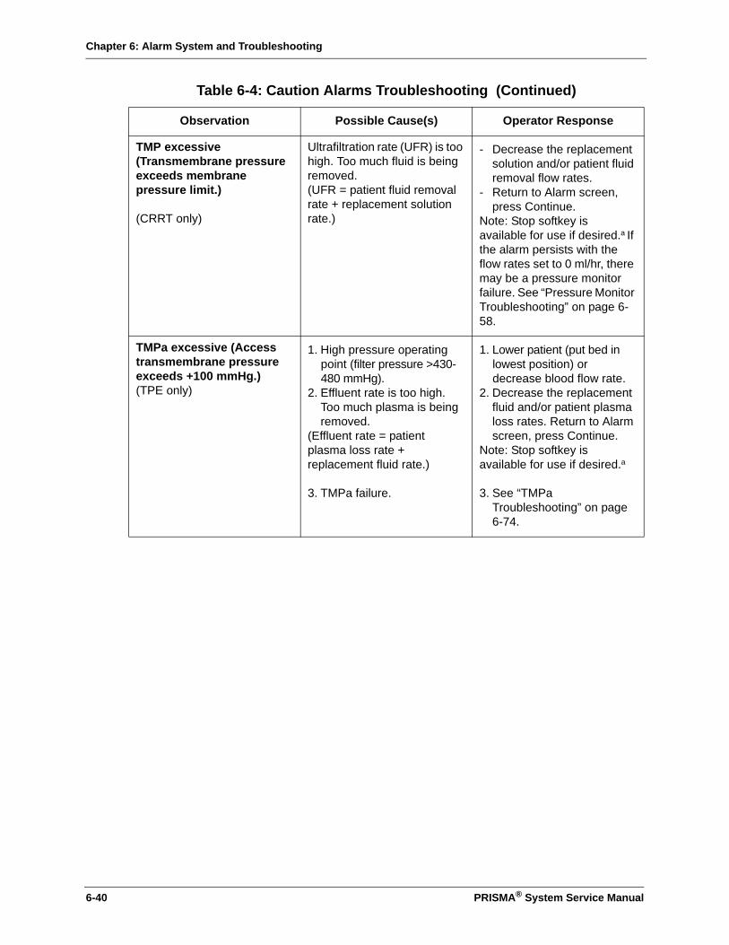
Chapter 6: Alarm System and Troubleshooting
TMP excessive(Transmembrane pressure exceeds membrane pressure limit.)
(CRRT only)
Ultrafiltration rate (UFR) is too high. Too much fluid is being removed.(UFR = patient fluid removal rate + replacement solution rate.)
- Decrease the replacement solution and/or patient fluid removal flow rates.
- Return to Alarm screen, press Continue.
Note: Stop softkey is available for use if desired.a If the alarm persists with the flow rates set to 0 ml/hr, there may be a pressure monitor failure. See “Pressure Monitor Troubleshooting” on page 6-58.
TMPa excessive (Access transmembrane pressure exceeds +100 mmHg.) (TPE only)
1. High pressure operating point (filter pressure >430-480 mmHg).
2. Effluent rate is too high. Too much plasma is being removed.
(Effluent rate = patient plasma loss rate + replacement fluid rate.)
3. TMPa failure.
1. Lower patient (put bed in lowest position) or decrease blood flow rate.
2. Decrease the replacement fluid and/or patient plasma loss rates. Return to Alarm screen, press Continue.
Note: Stop softkey is available for use if desired.a
3. See “TMPa Troubleshooting” on page 6-74.
Table 6-4: Caution Alarms Troubleshooting (Continued)
Observation Possible Cause(s) Operator Response
6-40 PRISMA® System Service Manual
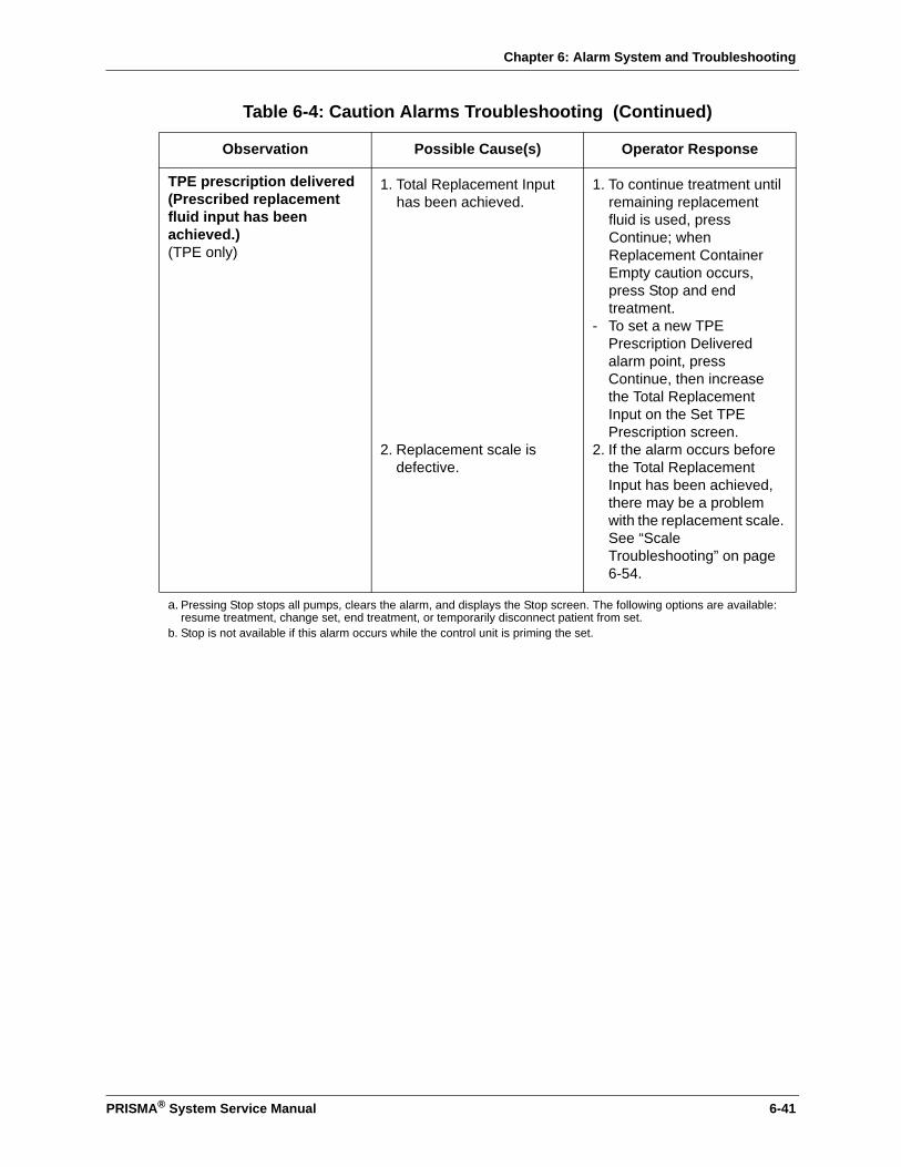
Chapter 6: Alarm System and Troubleshooting
TPE prescription delivered (Prescribed replacement fluid input has been achieved.) (TPE only)
1. Total Replacement Input has been achieved.
2. Replacement scale is defective.
1. To continue treatment until remaining replacement fluid is used, press Continue; when Replacement Container Empty caution occurs, press Stop and end treatment.
- To set a new TPE Prescription Delivered alarm point, press Continue, then increase the Total Replacement Input on the Set TPE Prescription screen.
2. If the alarm occurs before the Total Replacement Input has been achieved, there may be a problem with the replacement scale. See “Scale Troubleshooting” on page 6-54.
a. Pressing Stop stops all pumps, clears the alarm, and displays the Stop screen. The following options are available: resume treatment, change set, end treatment, or temporarily disconnect patient from set.
b. Stop is not available if this alarm occurs while the control unit is priming the set.
Table 6-4: Caution Alarms Troubleshooting (Continued)
Observation Possible Cause(s) Operator Response
PRISMA® System Service Manual 6-41
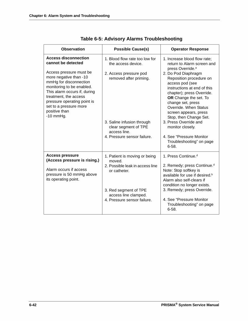
Chapter 6: Alarm System and Troubleshooting
Table 6-5: Advisory Alarms Troubleshooting
Observation Possible Cause(s) Operator Response
Access disconnection cannot be detected
Access pressure must be more negative than -10 mmHg for disconnection monitoring to be enabled. This alarm occurs if, during treatment, the access pressure operating point is set to a pressure more positive than -10 mmHg.
1. Blood flow rate too low for the access device.
2. Access pressure pod removed after priming.
3. Saline infusion through clear segment of TPE access line.
4. Pressure sensor failure.
1. Increase blood flow rate; return to Alarm screen and press Override.a
2. Do Pod Diaphragm Reposition procedure on access pod (see instructions at end of this chapter); press Override. OR Change the set. To change set, press Override. When Status screen appears, press Stop, then Change Set.
3. Press Override and monitor closely.
4. See “Pressure Monitor Troubleshooting” on page 6-58.
Access pressure(Access pressure is rising.)
Alarm occurs if access pressure is 50 mmHg above its operating point.
1. Patient is moving or being moved.
2. Possible leak in access line or catheter.
3. Red segment of TPE access line clamped.
4. Pressure sensor failure.
1. Press Continue.d
2. Remedy; press Continue.dNote: Stop softkey is available for use if desired.b Alarm also self-clears if condition no longer exists.3. Remedy; press Override.
4. See “Pressure Monitor Troubleshooting” on page 6-58.
6-42 PRISMA® System Service Manual
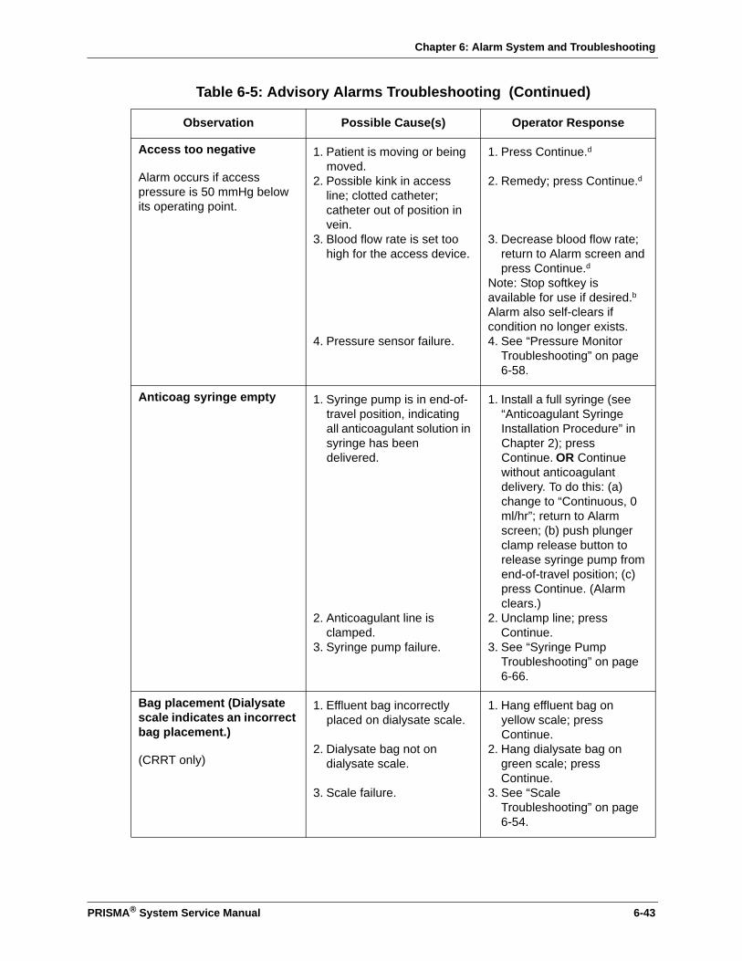
Chapter 6: Alarm System and Troubleshooting
Access too negative
Alarm occurs if access pressure is 50 mmHg below its operating point.
1. Patient is moving or being moved.
2. Possible kink in access line; clotted catheter; catheter out of position in vein.
3. Blood flow rate is set too high for the access device.
4. Pressure sensor failure.
1. Press Continue.d
2. Remedy; press Continue.d
3. Decrease blood flow rate; return to Alarm screen and press Continue.d
Note: Stop softkey is available for use if desired.b Alarm also self-clears if condition no longer exists.4. See “Pressure Monitor
Troubleshooting” on page 6-58.
Anticoag syringe empty 1. Syringe pump is in end-of-travel position, indicating all anticoagulant solution in syringe has been delivered.
2. Anticoagulant line is clamped.
3. Syringe pump failure.
1. Install a full syringe (see “Anticoagulant Syringe Installation Procedure” in Chapter 2); press Continue. OR Continue without anticoagulant delivery. To do this: (a) change to “Continuous, 0 ml/hr”; return to Alarm screen; (b) push plunger clamp release button to release syringe pump from end-of-travel position; (c) press Continue. (Alarm clears.)
2. Unclamp line; press Continue.
3. See “Syringe Pump Troubleshooting” on page 6-66.
Bag placement (Dialysate scale indicates an incorrect bag placement.)
(CRRT only)
1. Effluent bag incorrectly placed on dialysate scale.
2. Dialysate bag not on dialysate scale.
3. Scale failure.
1. Hang effluent bag on yellow scale; press Continue.
2. Hang dialysate bag on green scale; press Continue.
3. See “Scale Troubleshooting” on page 6-54.
Table 6-5: Advisory Alarms Troubleshooting (Continued)
Observation Possible Cause(s) Operator Response
PRISMA® System Service Manual 6-43

Chapter 6: Alarm System and Troubleshooting
Bag placement (Effluent scale indicates an incorrect bag placement.)
1. Replacement or dialysate bag incorrectly placed on effluent scale.
2. Foreign object on effluent scale.
3. Multiple effluent bags on effluent scale.
4. Scale failure.
1. Hang effluent bag on yellow scale; replacement bag on purple scale; dialysate bag on green scale; press Continue.
2. Remove foreign object; hang effluent bag on yellow scale; press Continue.
3. Hang one effluent bag on yellow scale; press Continue.
4. See “Scale Troubleshooting” on page 6-54.
Bag placement (Replacement scale indicates an incorrect bag placement.)
(CRRT only)
1. Effluent bag incorrectly placed on replacement scale.
2. Replacement bag not on replacement scale.
3. Scale failure.
1. Hang effluent bag on yellow scale; press Continue.
2. Hang replacement bag on purple scale; press Continue.
3. See “Scale Troubleshooting” on page 6-54.
Blood flow stopped (Machine has been left in the Stop screen for 60 seconds.)
Machine left in the Stop screen for more than 60 seconds (all pumps stopped).
- Inspect blood flowpath for signs of clotting. If clotted, change the set. (Press Continue to clear alarm and return to the Stop screen, then choose Change Set.)
- If flowpath not clotted, press Continue to clear alarm and return to the Stop screen.
Table 6-5: Advisory Alarms Troubleshooting (Continued)
Observation Possible Cause(s) Operator Response
6-44 PRISMA® System Service Manual

Chapter 6: Alarm System and Troubleshooting
Filter is clotting (TMP and/or ∆P filter is rising.)
Alarm occurs when one or both of the Filter is Clotting limits is reached. For more information, see “Filter Pressure—Filter Is Clotting Advisory Limit” in the Specifications chapter.
(CRRT only)
(continued on next page)
1. Filter is beginning to clot and/or TMP is rising. Note: Clotting is usually due to inadequate anticoagulation of the blood flowpath.
2. Replacement solution flow too high for filter in use.
(continued on next page)
1. Press Stop; change the set OR lower TMP by (a) decreasing the replacement and/or patient fluid removal rates, (b) increasing the blood flow rate. Press Overridea; continue to monitor the set. Test patient’s clotting parameters and adjust anticoagulant delivery if needed. Note: Filter Clotted warning occurs when the blood in the filter is clotted.
2. Press Stop; change the set OR lower TMP by (a) decreasing the replacement and/or patient fluid removal rates, (b) increasing the blood flow rate. Press Overridea; continue to monitor the set. Test patient’s clotting parameters and adjust anticoagulant delivery if needed. Note: Filter Clotted warning occurs when the blood in the filter is clotted.
(continued on next page)
Table 6-5: Advisory Alarms Troubleshooting (Continued)
Observation Possible Cause(s) Operator Response
PRISMA® System Service Manual 6-45
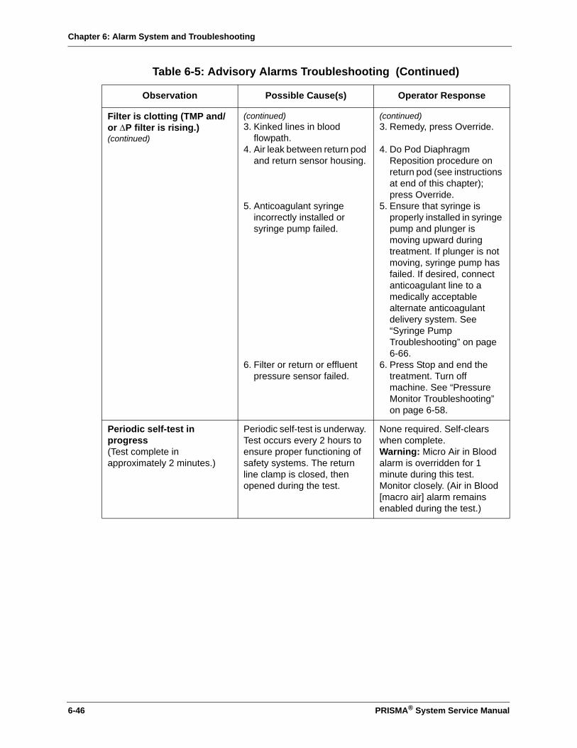
Chapter 6: Alarm System and Troubleshooting
Filter is clotting (TMP and/or ∆P filter is rising.)(continued)
(continued)3. Kinked lines in blood
flowpath.4. Air leak between return pod
and return sensor housing.
5. Anticoagulant syringe incorrectly installed or syringe pump failed.
6. Filter or return or effluent pressure sensor failed.
(continued)3. Remedy, press Override.
4. Do Pod Diaphragm Reposition procedure on return pod (see instructions at end of this chapter); press Override.
5. Ensure that syringe is properly installed in syringe pump and plunger is moving upward during treatment. If plunger is not moving, syringe pump has failed. If desired, connect anticoagulant line to a medically acceptable alternate anticoagulant delivery system. See “Syringe Pump Troubleshooting” on page 6-66.
6. Press Stop and end the treatment. Turn off machine. See “Pressure Monitor Troubleshooting” on page 6-58.
Periodic self-test in progress(Test complete in approximately 2 minutes.)
Periodic self-test is underway. Test occurs every 2 hours to ensure proper functioning of safety systems. The return line clamp is closed, then opened during the test.
None required. Self-clears when complete.Warning: Micro Air in Blood alarm is overridden for 1 minute during this test. Monitor closely. (Air in Blood [macro air] alarm remains enabled during the test.)
Table 6-5: Advisory Alarms Troubleshooting (Continued)
Observation Possible Cause(s) Operator Response
6-46 PRISMA® System Service Manual
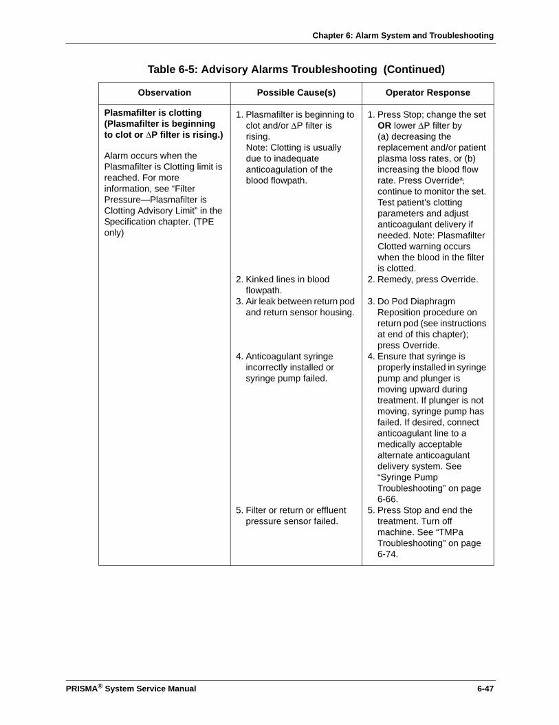
Chapter 6: Alarm System and Troubleshooting
Plasmafilter is clotting (Plasmafilter is beginning to clot or ∆P filter is rising.)
Alarm occurs when the Plasmafilter is Clotting limit is reached. For more information, see “Filter Pressure—Plasmafilter is Clotting Advisory Limit” in the Specification chapter. (TPE only)
1. Plasmafilter is beginning to clot and/or ∆P filter is rising. Note: Clotting is usually due to inadequate anticoagulation of the blood flowpath.
2. Kinked lines in blood flowpath.
3. Air leak between return pod and return sensor housing.
4. Anticoagulant syringe incorrectly installed or syringe pump failed.
5. Filter or return or effluent pressure sensor failed.
1. Press Stop; change the set OR lower ∆P filter by (a) decreasing the replacement and/or patient plasma loss rates, or (b) increasing the blood flow rate. Press Overridea; continue to monitor the set. Test patient’s clotting parameters and adjust anticoagulant delivery if needed. Note: Plasmafilter Clotted warning occurs when the blood in the filter is clotted.
2. Remedy, press Override.
3. Do Pod Diaphragm Reposition procedure on return pod (see instructions at end of this chapter); press Override.
4. Ensure that syringe is properly installed in syringe pump and plunger is moving upward during treatment. If plunger is not moving, syringe pump has failed. If desired, connect anticoagulant line to a medically acceptable alternate anticoagulant delivery system. See “Syringe Pump Troubleshooting” on page 6-66.
5. Press Stop and end the treatment. Turn off machine. See “TMPa Troubleshooting” on page 6-74.
Table 6-5: Advisory Alarms Troubleshooting (Continued)
Observation Possible Cause(s) Operator Response
PRISMA® System Service Manual 6-47
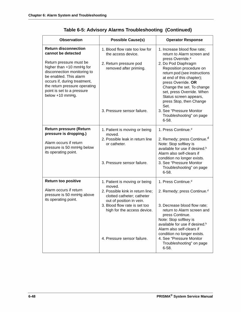
Chapter 6: Alarm System and Troubleshooting
Return disconnection cannot be detected
Return pressure must be higher than +10 mmHg for disconnection monitoring to be enabled. This alarm occurs if, during treatment, the return pressure operating point is set to a pressure below +10 mmHg.
1. Blood flow rate too low for the access device.
2. Return pressure pod removed after priming.
3. Pressure sensor failure.
1. Increase blood flow rate; return to Alarm screen and press Override.a
2. Do Pod Diaphragm Reposition procedure on return pod (see instructions at end of this chapter); press Override. OR Change the set. To change set, press Override. When Status screen appears, press Stop, then Change Set.
3. See “Pressure Monitor Troubleshooting” on page 6-58.
Return pressure (Return pressure is dropping.)
Alarm occurs if return pressure is 50 mmHg below its operating point.
1. Patient is moving or being moved.
2. Possible leak in return line or catheter.
3. Pressure sensor failure.
1. Press Continue.d
2. Remedy; press Continue.d Note: Stop softkey is available for use if desired.b Alarm also self-clears if condition no longer exists.3. See “Pressure Monitor
Troubleshooting” on page 6-58.
Return too positive
Alarm occurs if return pressure is 50 mmHg above its operating point.
1. Patient is moving or being moved.
2. Possible kink in return line; clotted catheter; catheter out of position in vein.
3. Blood flow rate is set too high for the access device.
4. Pressure sensor failure.
1. Press Continue.d
2. Remedy; press Continue.d
3. Decrease blood flow rate; return to Alarm screen and press Continue.
Note: Stop softkey is available for use if desired.b Alarm also self-clears if condition no longer exists.4. See “Pressure Monitor
Troubleshooting” on page 6-58.
Table 6-5: Advisory Alarms Troubleshooting (Continued)
Observation Possible Cause(s) Operator Response
6-48 PRISMA® System Service Manual

Chapter 6: Alarm System and Troubleshooting
Time for preventive maintenance
6500 hours of operation have elapsed.
Press Override; schedule preventive maintenance at earliest convenience.Note: This alarm must be cleared in Service mode by a trained and qualified technician.
Time to change set (Hours of use have reached the user-settable “Time to Change Set” advisory limit.)
Set has been used too long. Press Stope and change the set.OR Press Override and continue to monitor the set.cWarning: Do not use the PRISMA Set beyond 72 hours. Doing so could result in rupture of the pump segments, causing patient injury or death.
TMP too high (Transmembrane pressure has reached user-set pressure limit.)
(CRRT only)
1. Ultrafiltration rate (UFR) is too high for the present blood flow rate.
(UFR = patient fluid removal rate + replacement solution rate)
2. Replacement solution flow rate too high for filter in use.
3. Pressure monitor failure.
1. Decrease the replacement and/or patient fluid removal flow rates. OR Increase the blood flow rate.Return to Alarm screen and press Override.a
Note: Stop softkey is available for use if desired.b2. Decrease the replacement
and/or patient fluid removal flow rates. OR Increase the blood flow rate. Return to Alarm screen and press Override.a
Note: Stop softkey is available for use if desired.b 3. If the alarm persists with
the flow rates set to 0 ml/hr, there may be a pressure monitor failure. See “Pressure Monitor Troubleshooting” on page 6-58.
Table 6-5: Advisory Alarms Troubleshooting (Continued)
Observation Possible Cause(s) Operator Response
PRISMA® System Service Manual 6-49

Chapter 6: Alarm System and Troubleshooting
TMPa too high (Access transmembrane pressure has reached user-set pressure limit.)
(TPE only)
1. High pressure operating point (filter pressure >430-480 mmHg).
2. Effluent rate is too high for the present blood flow rate.
(Effluent rate = patient plasma loss rate + replacement fluid rate.)
3. TMPa failure.
1. Lower patient (put bed in lowest position) or decrease blood flow rate.
2. Decrease the replacement fluid and/or patient plasma loss rate. Increase blood flow rate or total replacement input. Return to Alarm screen and press Override.a
Note: Stop softkey is available for use if desired.b3. See “TMPa
Troubleshooting” on page 6-74.
a. Alarm can also be overridden if operator decides action is not necessary at this time. Alarm self-clears if condition no longer exists.
b. Pressing Stop stops all pumps, clears the alarm, and displays the Stop screen. The following options are available: resume treatment, change set, end treatment, or temporarily disconnect patient from set.
c. Alarm can also be overridden if operator decides action is not necessary at this time. Alarm clears when set is unloaded.
d. Continue resets all operating points and clears the alarm.e. Pressing Stop stops all pumps and displays the Stop screen. The set can be changed by pressing Change Set on the
Stop screen. Alarm clears when set is unloaded.
Table 6-6: Additional Troubleshooting
Observation Possible Cause(s) Operator Response
Cartridge carrier is flush with front panel of machine, so that a set cannot be loaded.
1. Last set was manually disconnected.
2. Cartridge carrier failure.
1. -Begin normal Setup procedure. When Load Set screen appears, press Load.-When Prepare Solutions screen appears, press Unload. (Places cartridge carrier in correct position.)-When Load Set screen reappears, follow on-line instructions to load the set.
2. See “Cartridge Carrier Troubleshooting” on page 6-65.
Display goes blank momentarily, then screen reappears.
Power was lost and restored within 15 seconds.
None required.
Table 6-5: Advisory Alarms Troubleshooting (Continued)
Observation Possible Cause(s) Operator Response
6-50 PRISMA® System Service Manual

Chapter 6: Alarm System and Troubleshooting
Display goes blank or logo screen fails to leave display; status lights may still be on; no buzzer.
Internal power supply failure; internal malfunction.
- Turn off the machine; end treatment manually, if desired.a
- See “Power Supply Troubleshooting” on page 6-68.
- One at a time, replace all CCAs to determine the problem.
Warning: If doing Manual Termination With Blood Return, air detection is not provided. Watch return line for air.
Display goes blank; status lights go off; non-mutable buzzer sounds.
Power loss; internal power supply failure.
Turn off machine to stop buzzer; end treatment manually, if desired.aWarning: If doing Manual Termination With Blood Return, air detection is not provided. Watch return line for air. See “Power Supply Troubleshooting” on page 6-68.
Table 6-6: Additional Troubleshooting (Continued)
Observation Possible Cause(s) Operator Response
PRISMA® System Service Manual 6-51

Chapter 6: Alarm System and Troubleshooting
Effluent bag is tinged pink or red.
1. Patient’s disease state may cause discoloration of the effluent.
2. Effluent contains red blood cells, but level is below blood leak detection limit.
3. Hemolysis is occurring due to occlusion.
4. Hemolysis is occurring during TPE.
1. Send effluent sample to laboratory for analysis. If free of red blood cells, continue treatment. If red blood cells are present, change the set.
2. Send effluent sample to laboratory for analysis. If red blood cells are present, change the set.
3. Verify that the correct clamps are open for the therapy in use, especially for the access line (red) and return line (blue). Verify no kinks in the access and return lines. If hemolysis continues, change the set via the Stop key.b
4. Set replacement rate and plasma loss rate (if any) to 0 ml/hr. After hemolysis stops, set these rates to values lower than those in effect when hemolysis occurred. Note: Physician must prescribe these new rates.
Leakage from set connections.
Connections are loose. - Tighten the connections.- If leakage continues,
change the set via Stop key.b
Softkeys won’t work. Touchscreen failed. - Turn off machine; end treatment manually, if desired.a
- See “Display Troubleshooting” on page 6-68.
Warning: If doing Manual Termination With Blood Return, air detection is not provided. Watch return line for air.
Table 6-6: Additional Troubleshooting (Continued)
Observation Possible Cause(s) Operator Response
6-52 PRISMA® System Service Manual

Chapter 6: Alarm System and Troubleshooting
Unable to Normalize BLD 1. Blood in effluent line.
2. Air bubble in effluent line at level of blood leak detector.
3. Effluent line not properly installed in blood leak detector.
4. Liquid or other debris in tubing path through the detector.
5. Leak in filter membrane.
6. TPE therapy: formed elements or lipids in plasma, discolored plasma.
7. Blood leak detector failure.
1. Wait for blood to clear and BLD signal value to be ≥150 before normalizing OR change the set.
2. Dislodge bubble by giving the effluent pump a quick half-turn counterclockwise.
3. Press line into detector from the bottom up and route securely through tubing guides.
4. Remove line from detector. Using a “flossing” action, clean inside the detector with a lint-free cloth and isopropyl alcohol. Dry thoroughly. Clean effluent line with water and dry thoroughly. Reinsert line into detector and tubing guides.
Warning: If the effluent line is repositioned or removed/reinserted in detector, the detector must be reset by pressing Normalize BLD. This must be done before continuing patient treatment. BLD signal value must be ≥150 for normalization to be allowed.5. Change the set via the
Stop key.b6. Lower replacement rate
and/or patient plasma loss rate.
7. See “Blood Leak Detector Alarm Troubleshooting” on page 6-66.
a. Manual termination instructions are provided at the end of this chapter.b. See “Change Set Procedure” in the Operation section of the appropriate chapter of the operators manual (3 or 4).
Table 6-6: Additional Troubleshooting (Continued)
Observation Possible Cause(s) Operator Response
PRISMA® System Service Manual 6-53

Chapter 6: Troubleshooting
Component and System Troubleshooting
Table 6-7: Scale Troubleshooting
Observation Response
The Lower End of One of the Scale Readings is Inaccurate
Check for a malfunctioning scale
1. Something may be preventing the scale assembly from moving to the top of its normal range - check the scale assembly for obstructions.
2. Enter the Service-Calibrate-Scale mode and calibrate the scale.
3. Locate another scale that is working properly. Turn off the machine and move the scale connectors from a scale that is working to the scale that is not working. (For example, move the effluent scale to the dialysate scale and the dialysate scale to the effluent scale.)
Effluent scale connectors: Analog CCA, J5 (monitor) and J9 (control).Replacement scale connectors: Analog CCA, J6, (monitor) and J10 (control).Dialysate scale connectors: Analog CCA, J8, (monitor) and J11 (control).
4. Turn the machine on and enter the Service-Diagnose-Scale mode. If the same scale still does not work, replace the scale and re-calibrate. If you wish to check the scale amplifier output signals, you may do so at the following points:
Monitor portion of the Analog CCAEffluent scale: U33 pin 2: 2600 g = 0.0 to –0.5 mVdcReplacement scale: U33 pin10: 2600 g = 0.0 to –0.5 mVdcDialysate scale: U36 pin 2: 2600 g = 0.0 to –0.5 mVdc
Control portion of the Analog CCAEffluent scale: U52 pin 2: 2600 g = 0.0 to –0.5 mVdcReplacement scale: U52 pin 10: 2600 g = 0.0 to –0.5 mVdcDialysate scale: U58 pin 2: 2600 g = 0.0 to –0.5 mVdc
5. If the scale is replaced and the problem still exists, replace the Analog CCA.
6-54 PRISMA® System Service Manual
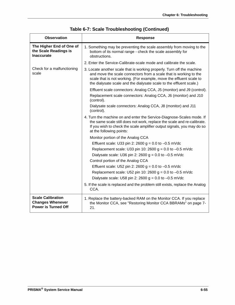
Chapter 6: Troubleshooting
The Higher End of One of the Scale Readings is Inaccurate
Check for a malfunctioning scale
1. Something may be preventing the scale assembly from moving to the bottom of its normal range - check the scale assembly for obstructions.
2. Enter the Service-Calibrate-scale mode and calibrate the scale.
3. Locate another scale that is working properly. Turn off the machine and move the scale connectors from a scale that is working to the scale that is not working. (For example, move the effluent scale to the dialysate scale and the dialysate scale to the effluent scale.)
Effluent scale connectors: Analog CCA, J5 (monitor) and J9 (control).Replacement scale connectors: Analog CCA, J6 (monitor) and J10 (control).Dialysate scale connectors: Analog CCA, J8 (monitor) and J11 (control).
4. Turn the machine on and enter the Service-Diagnose-Scales mode. If the same scale still does not work, replace the scale and re-calibrate. If you wish to check the scale amplifier output signals, you may do so at the following points:
Monitor portion of the Analog CCA Effluent scale: U33 pin 2: 2600 g = 0.0 to –0.5 mVdcReplacement scale: U33 pin 10: 2600 g = 0.0 to –0.5 mVdcDialysate scale: U36 pin 2: 2600 g = 0.0 to –0.5 mVdc
Control portion of the Analog CCAEffluent scale: U52 pin 2: 2600 g = 0.0 to –0.5 mVdcReplacement scale: U52 pin 10: 2600 g = 0.0 to –0.5 mVdcDialysate scale: U58 pin 2: 2600 g = 0.0 to –0.5 mVdc
5. If the scale is replaced and the problem still exists, replace the Analog CCA.
Scale Calibration Changes Whenever Power is Turned Off
1. Replace the battery-backed RAM on the Monitor CCA. If you replace the Monitor CCA, see "Restoring Monitor CCA BBRAMs" on page 7-21.
Table 6-7: Scale Troubleshooting (Continued)
Observation Response
PRISMA® System Service Manual 6-55

Chapter 6: Troubleshooting
One Scale is Not Working (The readings do not change)
Check for a malfunctioning scale
Check the cables and connections
1. Check the connectors that go from the scale to the monitor and the control portion of the Analog CCA. Repair as necessary.
Effluent scale connectors: Analog CCA: J5 (monitor) and J9 (control).Replacement scale connectors: Analog CCA: J6 (monitor) and J10 (control).Dialysate scale connectors: Analog CCA: J8 (monitor) and J11 (control).
2. Enter the Service-Diagnose-Scales mode and examine the control and monitor scale values. Each value should be within ±10 counts of each other. If they are not, proceed to step 3. If they are, proceed to step 5.
3. Locate another scale that is working properly. Turn off the machine and move the scale connectors from a scale that is working to the scale that is not working. For example, move the effluent scale to the dialysate scale and the dialysate scale to the effluent scale.
4. Turn the machine on and enter the Service-Diagnose-Scales mode. If the same scale still does not work, replace the scale and re-calibrate. If you wish to check the scale amplifier output signals, you may do so at the following points:
Monitor portion of the Analog CCAEffluent scale: U33 pin 2: 2600 g = 0.0 to –0.5 mVdcReplacement scale: U33 pin 10: 2600 g = 0.0 to –0.5 mVdcDialysate scale: U36 pin 2: 2600 g = 0.0 to –0.5 mVdc
Control portion of the Analog CCAEffluent scale: U52 pin 2: 2600 g = 0.0 to –0.5 mVdcReplacement scale: U52 pin 10: 2600 g = 0.0 to –0.5 mVdcDialysate scale: U58 pin 2: 2600 g = 0.0 to –0.5 mVdc
5. If one set of values (control and monitor) are not within specification, replace the Analog CCA. If both sets of values are within specification, check the cable and connectors between the Analog CCA (J7) and the Monitor CCA (J5). Repair or replace the cable as necessary.
6. If the Monitor values displayed on the Service-Diagnose-Scales screen are not correct or do not change, check the cable and connectors between the Monitor CCA (J5) and the Controller CCA (J2). Repair or replace the cable as necessary.
7. If the Control values displayed on the Service-Diagnose-Scales screen are not correct or do not change, replace the Controller CCA.
Table 6-7: Scale Troubleshooting (Continued)
Observation Response
6-56 PRISMA® System Service Manual

Chapter 6: Troubleshooting
All Scale Values Are Not Functioning
Check the Analog CCA
Check the cables and connections
1. Enter the Service-Diagnose-Scales mode and check the scale amplifier output signals at the points listed below. All voltages must be greater than 1 Vac.
Monitor portion of the AnalogEffluent scale: U33 pin 2: 2600 g = 0.0 to –0.5 mVdcReplacement scale: U33 pin 10: 2600 g = 0.0 to –0.5 mVdcDialysate scale: U36 pin2: 2600 g = 0.0 to –0.5 mVdc
Control portion of the Analog CCAEffluent scale: U52 pin 2: 2600 g = 0.0 to –0.5 mVdcReplacement scale: U52 pin 10: 2600 g = 0.0 to –0.5 mVdcDialysate scale: U58 pin 2: 2600 g = 0.0 to –0.5 mVdc
If any of the voltages are not greater than 1 Vac, replace the Analog CCA.
2. If both control and monitor circuits have failed, check the C_CK1.95 KHz signal at U47 pin 1 (monitor-side) or U53 pin 1 (control-side). The voltage should be greater than 1 Vac. If the voltage is within specification at either location, the Analog CCA is defective and requires replacement. If the voltage is missing at both locations, check the connector between the Analog CCA (J7) and the Controller CCA (J2). Repair or replace the cable as necessary.
3. If the above steps still do not correct the problem, replace the Controller CCA.
Table 6-7: Scale Troubleshooting (Continued)
Observation Response
PRISMA® System Service Manual 6-57

Chapter 6: Troubleshooting
Table 6-8: Pressure Monitor Troubleshooting
Observation Response
One of the Pressure Readings is Inaccurate or One of the Pressure Readings Does Not Change (remains at a single value)
Check for a malfunctioning pressure transducer
1. Attach a pressure test pod assembly to the machine and apply a pressure. Enter the Service-Calibration-Pressures screen and calibrate the pressure transducer. If the pressure transducer cannot be calibrated, proceed to step 2.
2. Turn the machine off, open the rear panel of the machine. Locate the signal cable for the pressure transducer that is not functioning properly and a signal cable for another pressure transducer that is functioning properly. Place the signal cable from the properly functioning pressure transducer on the improperly functioning transducer.
On the Analog CCA, J1 = effluent transducer, J2 = return transducer, J3 = access transducer, J4 = filter transducer
3. Turn the machine on and enter the Service-Diagnose-Pressures screen. If the original malfunctioning pressure circuit now functions properly, replace the pressure transducer. If the original malfunctioning pressure circuit still does not function properly, replace the Analog CCA.
If you wish to check the pressure transducer amplifier output signals, connect the voltmeter to the following IC leads:
Return = PDET1 = U8 pin 2Effluent = PDET2 = U8 pin 10Filter = PDET3 = U21 pin 2Access = PDET4 = U21 pin 10The voltage-to-pressure rate is approximately 5 mV/mmHg.
4. If the problem remains after performing the steps above, replace the Monitor CCA. If you replace the Monitor CCA, see "Restoring Monitor CCA BBRAMs" on page 7-21.
None of the Pressure Readings are Changing
Check the Analog CCA
Check the CARP 1 and 2 signals.
1. Check the Analog-to-Monitor CCA cable (J7 on the Analog CCA, J5 on the Monitor CCA).
2. Attach a pressure test pod assembly (a pressure meter, syringe, stopcock, tubing, and pressure port) to the machine and apply a pressure.
3. Using a voltmeter, check the voltage on the Analog CCA at U11 pin 1 and U17 pin 9. The voltage should be approximately 2 Vac. If not replace the Controller CCA.
4. Using a voltmeter, check the voltage at U18 pin 1 (CARP 1 signal). The voltage should be greater than 1 Vac. Check the voltage at U18 pin 7 (CARP 2 signal). The voltage should be greater than 1 Vac. If either or both signals are less than 1 Vac, replace the Analog CCA. If both voltages are greater than 1 Vac, replace the Analog or Monitor CCA. If you replace the Monitor CCA, see "Restoring Monitor CCA BBRAMs" on page 7-21.
6-58 PRISMA® System Service Manual
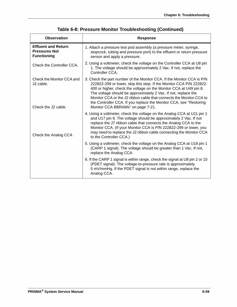
Chapter 6: Troubleshooting
Effluent and Return Pressures Not Functioning
Check the Controller CCA.
Check the Monitor CCA and J2 cable.
Check the J2 cable.
Check the Analog CCA
1. Attach a pressure test pod assembly (a pressure meter, syringe, stopcock, tubing and pressure port) to the effluent or return pressure sensor and apply a pressure.
2. Using a voltmeter, check the voltage on the Controller CCA at U8 pin 1. The voltage should be approximately 2 Vac. If not, replace the Controller CCA.
3. Check the part number of the Monitor CCA. If the Monitor CCA is P/N 222822-299 or lower, skip this step. If the Monitor CCA P/N 222822-400 or higher, check the voltage on the Monitor CCA at U49 pin 8. The voltage should be approximately 2 Vac. If not, replace the Monitor CCA or the J2 ribbon cable that connects the Monitor CCA to the Controller CCA. If you replace the Monitor CCA, see "Restoring Monitor CCA BBRAMs" on page 7-21.
4. Using a voltmeter, check the voltage on the Analog CCA at U11 pin 1 and U17 pin 9. The voltage should be approximately 2 Vac. If not replace the J7 ribbon cable that connects the Analog CCA to the Monitor CCA. (If your Monitor CCA is P/N 222822-299 or lower, you may need to replace the J2 ribbon cable connecting the Monitor CCA to the Controller CCA.)
5. Using a voltmeter, check the voltage on the Analog CCA at U18 pin 1 (CARP 1 signal). The voltage should be greater than 1 Vac. If not, replace the Analog CCA.
6. If the CARP 1 signal is within range, check the signal at U8 pin 2 or 10 (PDET signal). The voltage-to-pressure rate is approximately 5 mV/mmHg. If the PDET signal is not within range, replace the Analog CCA.
Table 6-8: Pressure Monitor Troubleshooting (Continued)
Observation Response
PRISMA® System Service Manual 6-59
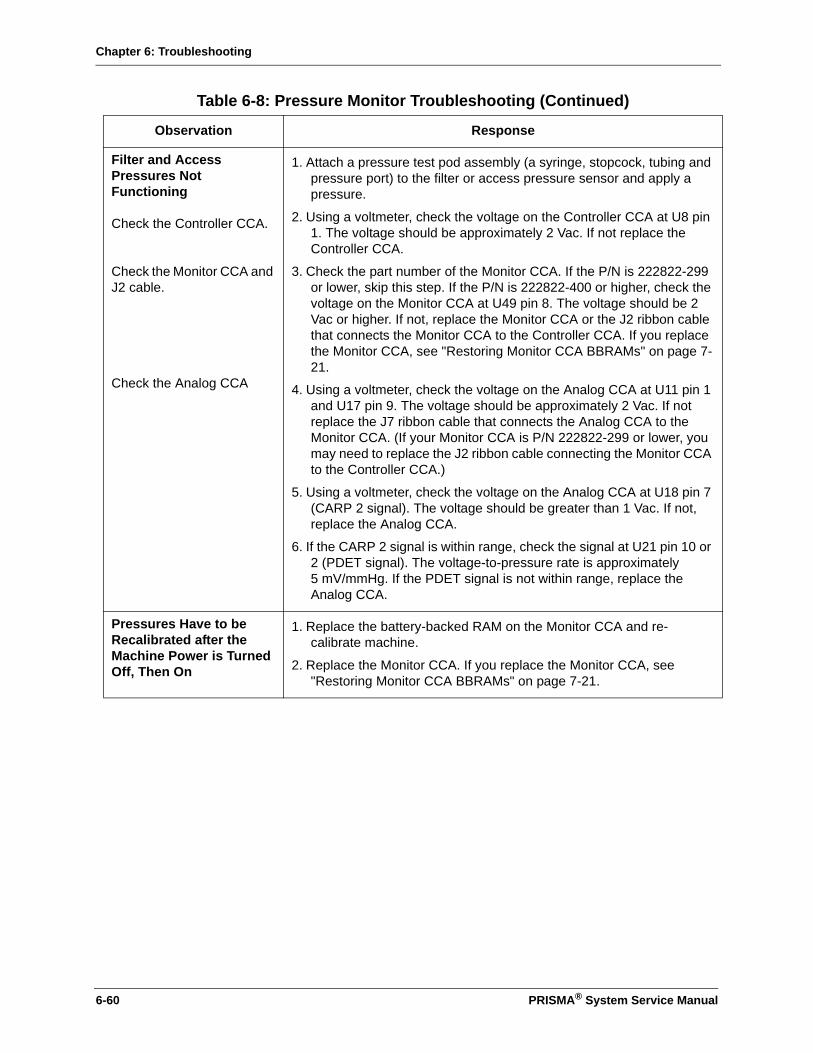
Chapter 6: Troubleshooting
Filter and Access Pressures Not Functioning
Check the Controller CCA.
Check the Monitor CCA and J2 cable.
Check the Analog CCA
1. Attach a pressure test pod assembly (a syringe, stopcock, tubing and pressure port) to the filter or access pressure sensor and apply a pressure.
2. Using a voltmeter, check the voltage on the Controller CCA at U8 pin 1. The voltage should be approximately 2 Vac. If not replace the Controller CCA.
3. Check the part number of the Monitor CCA. If the P/N is 222822-299 or lower, skip this step. If the P/N is 222822-400 or higher, check the voltage on the Monitor CCA at U49 pin 8. The voltage should be 2 Vac or higher. If not, replace the Monitor CCA or the J2 ribbon cable that connects the Monitor CCA to the Controller CCA. If you replace the Monitor CCA, see "Restoring Monitor CCA BBRAMs" on page 7-21.
4. Using a voltmeter, check the voltage on the Analog CCA at U11 pin 1 and U17 pin 9. The voltage should be approximately 2 Vac. If not replace the J7 ribbon cable that connects the Analog CCA to the Monitor CCA. (If your Monitor CCA is P/N 222822-299 or lower, you may need to replace the J2 ribbon cable connecting the Monitor CCA to the Controller CCA.)
5. Using a voltmeter, check the voltage on the Analog CCA at U18 pin 7 (CARP 2 signal). The voltage should be greater than 1 Vac. If not, replace the Analog CCA.
6. If the CARP 2 signal is within range, check the signal at U21 pin 10 or 2 (PDET signal). The voltage-to-pressure rate is approximately 5 mV/mmHg. If the PDET signal is not within range, replace the Analog CCA.
Pressures Have to be Recalibrated after the Machine Power is Turned Off, Then On
1. Replace the battery-backed RAM on the Monitor CCA and re-calibrate machine.
2. Replace the Monitor CCA. If you replace the Monitor CCA, see "Restoring Monitor CCA BBRAMs" on page 7-21.
Table 6-8: Pressure Monitor Troubleshooting (Continued)
Observation Response
6-60 PRISMA® System Service Manual

Chapter 6: Troubleshooting
Table 6-9: Air Bubble Detector Troubleshooting
Observation Response
Micro Air in Blood AlarmCheck the air bubble transducer
Check the Detector CCA
1. Place a fluid-filled tube in the air bubble detector. Ensure that no air bubbles are present.
2. Connect a voltmeter to TB2 on the Detector CCA. The voltage should be +2.5 Vdc. If not, check the cable and connection between the air bubble transducer and the Detector CCA (J2). If faulty cable connections are not the problem, replace the air bubble transducer.
3. If replacing the transducer does not repair the problem, replace the Detector CCA. If the +2.5 Vdc at TB2 is working, check TB24. If TB24 is less than +1 Vdc, the monitor-side comparator is working properly. If TB24 is greater than +2.5 Vdc, the output of either U2-C or U1-A is defective. Replace the Detector CCA.
4. Connect a voltmeter to TB25 on the Detector CCA. If it is less than +1 Vdc, the control-side comparator is working properly. If TB25 is greater than +2.5 Vdc, the output of either U2C or U1A is defective. Replace the Detector CCA.
5. Check U59 pin 3 on the Monitor CCA. If the voltage is less than +3.5 Vdc replace the cable between the Detector CCA (J1) and the Monitor CCA (J7). If the voltage is greater than +3.5 Vdc at U59 pin 3, replace the Monitor CCA. If you replace the Monitor CCA, see "Restoring Monitor CCA BBRAMs" on page 7-21.
Air in Blood AlarmCheck the air bubble transducer
Check the Detector CCA
1. Place a fluid-filled tube in the air bubble detector. Ensure that no air bubbles are present.
2. Connect a voltmeter to TB2 on the Detector CCA. The voltage should be +2.5 Vdc. If not, check the cable and connection between the air bubble transducer and the Detector CCA (J2). If faulty cable connections are not the problem, replace the air bubble transducer.
3. If replacing the transducer still does not repair the problem, replace the Detector CCA. If TB2 still reads +2.5 Vdc, check TB8 on the Detector CCA. If TB8 is greater than +2.5 Vdc, the monitor-side comparator is working properly. If TB8 is less than +1 Vdc, the output of U2-B is defective. Replace the Detector CCA.
4. Check TB9. If it is less than +1 Vdc, the output of U9 is defective. Replace the Detector CCA.
5. Check U59 pin 3 on the Monitor CCA. If the voltage is less than +3.5 Vdc replace the cable between the Detector CCA (J1) and the Monitor CCA (J7). If the voltage is greater than +3.5 Vdc at U59 pin 3, replace the Monitor CCA. If you replace the Monitor CCA, see "Restoring Monitor CCA BBRAMs" on page 7-21.
PRISMA® System Service Manual 6-61
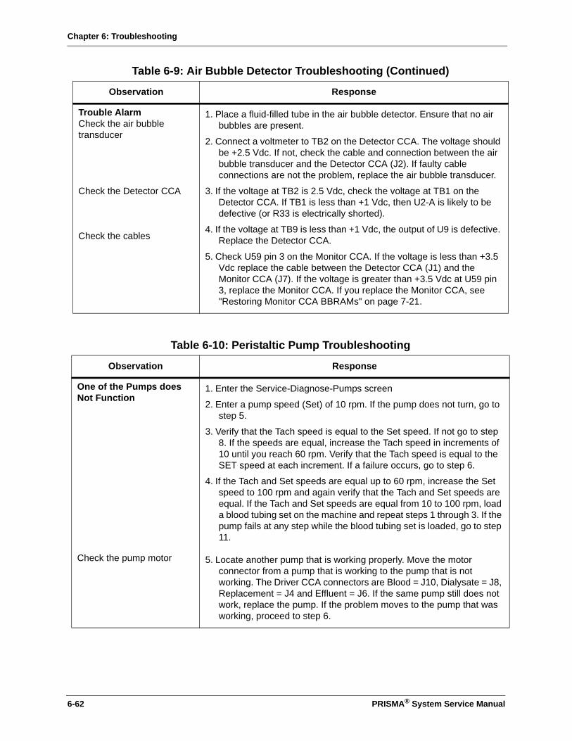
Chapter 6: Troubleshooting
Trouble AlarmCheck the air bubble transducer
Check the Detector CCA
Check the cables
1. Place a fluid-filled tube in the air bubble detector. Ensure that no air bubbles are present.
2. Connect a voltmeter to TB2 on the Detector CCA. The voltage should be +2.5 Vdc. If not, check the cable and connection between the air bubble transducer and the Detector CCA (J2). If faulty cable connections are not the problem, replace the air bubble transducer.
3. If the voltage at TB2 is 2.5 Vdc, check the voltage at TB1 on the Detector CCA. If TB1 is less than +1 Vdc, then U2-A is likely to be defective (or R33 is electrically shorted).
4. If the voltage at TB9 is less than +1 Vdc, the output of U9 is defective. Replace the Detector CCA.
5. Check U59 pin 3 on the Monitor CCA. If the voltage is less than +3.5 Vdc replace the cable between the Detector CCA (J1) and the Monitor CCA (J7). If the voltage is greater than +3.5 Vdc at U59 pin 3, replace the Monitor CCA. If you replace the Monitor CCA, see "Restoring Monitor CCA BBRAMs" on page 7-21.
Table 6-10: Peristaltic Pump Troubleshooting
Observation Response
One of the Pumps does Not Function
1. Enter the Service-Diagnose-Pumps screen
2. Enter a pump speed (Set) of 10 rpm. If the pump does not turn, go to step 5.
3. Verify that the Tach speed is equal to the Set speed. If not go to step 8. If the speeds are equal, increase the Tach speed in increments of 10 until you reach 60 rpm. Verify that the Tach speed is equal to the SET speed at each increment. If a failure occurs, go to step 6.
4. If the Tach and Set speeds are equal up to 60 rpm, increase the Set speed to 100 rpm and again verify that the Tach and Set speeds are equal. If the Tach and Set speeds are equal from 10 to 100 rpm, load a blood tubing set on the machine and repeat steps 1 through 3. If the pump fails at any step while the blood tubing set is loaded, go to step 11.
Check the pump motor 5. Locate another pump that is working properly. Move the motor connector from a pump that is working to the pump that is not working. The Driver CCA connectors are Blood = J10, Dialysate = J8, Replacement = J4 and Effluent = J6. If the same pump still does not work, replace the pump. If the problem moves to the pump that was working, proceed to step 6.
Table 6-9: Air Bubble Detector Troubleshooting (Continued)
Observation Response
6-62 PRISMA® System Service Manual

Chapter 6: Troubleshooting
Check the Driver CCA to pump motor cabling
Check the Driver CCA
Check the Driver CCA- to-Controller CCA cables and connections
6. Use a voltmeter to check the pump driver output on the Driver CCA.
Blood pump: U46, pins 2 and 10, U50, pins 2 and 10Dialysate pump: U34, pins 2 and 10, U38, pins 2 and 10Replacement pump: U10, pins 2 and 10, U14, pins 2 and 10Effluent pump: U22, pins 2 and 10, U26, pins 2 and 10
The voltage should be less than 1.5 Vdc when the pump motor is off. The voltage should be greater than 8 Vdc when the pump motor is on. If the voltage is less than 8 Vdc the cable and motor are operating properly. Go to step 7 to determine if the inputs are correct.
7. Use a voltmeter to check the input on the Driver CCA:
Blood pump: U48, pins 2, 26, and 27Dialysate pump: U36, pins 2, 26, and 27Replacement pump: U12, pins 2, 26, and 27Effluent pump: U24, 2, 26, and 27
All inputs should be +5 Vdc when the SET speed is 10 rpm. After checking these inputs, use a voltmeter to check the clock input on the Driver CCA:
Blood pump: U45, pin 10 (C_BP_CLK)Dialysate pump: U33, pin 10 (C_DIA_CLK)Replacement pump: U9, pin 10 (C_REP_CLK)Effluent pump: U21, pin 10 (C_WST_CLK)
The clock input signals should be between +1.5 and +3.5 Vdc.• If all of the signal measured in this step are within the
specifications stated in this step, replace the Driver CCA. • If all of the signals measured in this step are NOT within
specification, go to step 8.
8. Disconnect the cable between the Driver CCA and the Controller CCA. Measure the following voltages on the Controller CCA. All outputs should be +5 Vdc when the Set speed is 10 rpm.
Blood pump: U25, pins 19, 20, and 21Dialysate pump: U25, pins 1, 40, and 39Replacement pump: U25, pins 4, 3, and 2Effluent pump: U25, 38, 37, and 18
The clock output signals should be between +1.5 and +3.5 Vdc.Blood pump: U11, pin 10 (C_BP_CLK)Dialysate pump: U12, pin 10 (C_DIA_CLK)Replacement pump: U17, pin 10 (C_REP_CLK)Effluent pump: U11, pin 13 (C_WST_CLK)
Table 6-10: Peristaltic Pump Troubleshooting (Continued)
Observation Response
PRISMA® System Service Manual 6-63
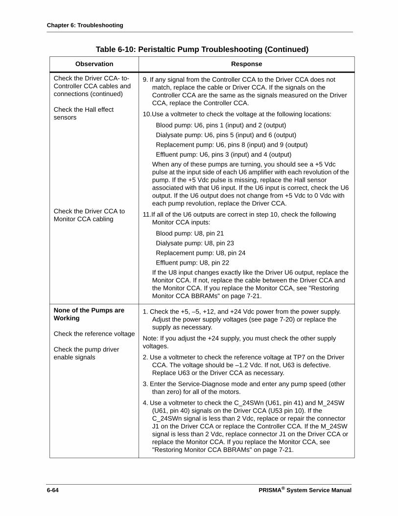
Chapter 6: Troubleshooting
Check the Driver CCA- to-Controller CCA cables and connections (continued)
Check the Hall effect sensors
Check the Driver CCA to Monitor CCA cabling
9. If any signal from the Controller CCA to the Driver CCA does not match, replace the cable or Driver CCA. If the signals on the Controller CCA are the same as the signals measured on the Driver CCA, replace the Controller CCA.
10.Use a voltmeter to check the voltage at the following locations:
Blood pump: U6, pins 1 (input) and 2 (output)Dialysate pump: U6, pins 5 (input) and 6 (output)Replacement pump: U6, pins 8 (input) and 9 (output)Effluent pump: U6, pins 3 (input) and 4 (output)
When any of these pumps are turning, you should see a +5 Vdc pulse at the input side of each U6 amplifier with each revolution of the pump. If the +5 Vdc pulse is missing, replace the Hall sensor associated with that U6 input. If the U6 input is correct, check the U6 output. If the U6 output does not change from +5 Vdc to 0 Vdc with each pump revolution, replace the Driver CCA.
11.If all of the U6 outputs are correct in step 10, check the following Monitor CCA inputs:
Blood pump: U8, pin 21Dialysate pump: U8, pin 23Replacement pump: U8, pin 24Effluent pump: U8, pin 22
If the U8 input changes exactly like the Driver U6 output, replace the Monitor CCA. If not, replace the cable between the Driver CCA and the Monitor CCA. If you replace the Monitor CCA, see "Restoring Monitor CCA BBRAMs" on page 7-21.
None of the Pumps are Working
Check the reference voltage
Check the pump driver enable signals
1. Check the +5, –5, +12, and +24 Vdc power from the power supply. Adjust the power supply voltages (see page 7-20) or replace the supply as necessary.
Note: If you adjust the +24 supply, you must check the other supply voltages.
2. Use a voltmeter to check the reference voltage at TP7 on the Driver CCA. The voltage should be –1.2 Vdc. If not, U63 is defective. Replace U63 or the Driver CCA as necessary.
3. Enter the Service-Diagnose mode and enter any pump speed (other than zero) for all of the motors.
4. Use a voltmeter to check the C_24SWn (U61, pin 41) and M_24SW (U61, pin 40) signals on the Driver CCA (U53 pin 10). If the C_24SWn signal is less than 2 Vdc, replace or repair the connector J1 on the Driver CCA or replace the Controller CCA. If the M_24SW signal is less than 2 Vdc, replace connector J1 on the Driver CCA or replace the Monitor CCA. If you replace the Monitor CCA, see "Restoring Monitor CCA BBRAMs" on page 7-21.
Table 6-10: Peristaltic Pump Troubleshooting (Continued)
Observation Response
6-64 PRISMA® System Service Manual

Chapter 6: Troubleshooting
Table 6-11: Cartridge Carrier Troubleshooting
Observation Response
The Cartridge Carrier Will Load but Not Unload, or, Will Unload but Not Load
Check the Driver CCA to Controller CCA cable and Controller CCA
1. Enter the Service-Diagnose mode.
2. Connect a voltmeter to J2-8 (C_LOAD_DIR_TST) on the Controller CCA. Then press the Load/Unload softkey on the display. The signal at J2-8 should be +5 Vdc when the Load softkey is pressed and 0 Vdc when the Unload softkey is pressed.
3. Remove the cable between the Controller CCA and the Driver CCA and again check the signal at J2-8. If the signal at J2-8 now functions correctly, replace the cable. If the signal still does not function correctly, replace the PIA or the Controller CCA as necessary.
The Cartridge Carrier does Not Load or Unload the Set
Check the Driver CCA to Controller CCA cable
Check the mechanical system and Driver CCA
1. Enter the Service-Diagnose mode.
2. Connect a voltmeter to J2-7 (C_LOAD_EN_TST) on the Controller CCA. When the Load/Unload softkey is pressed, the signal should be +5 Vdc when loading or unloading. The signal should be 0 Vdc when the loading or unloading is complete.
3. Remove the cable between the Driver CCA and the Controller CCA. If the signal now functions correctly, replace the cable. If the signals are still not functioning correctly after replacing the cable, replace the Controller CCA.
4. If the signals are functioning correctly, connect a voltmeter to Driver CCA connector J15, pin 5. When the cartridge carrier is NOT loading or unloading, the signal should be +24 Vdc. When the cartridge carrier is loading or unloading, the signal should be less than +19 Vdc.
If the signal is greater than +19 Vdc during loading or unloading, replace the assembly. If the signal is less than +19 Vdc, check the cartridge carrier assembly for mechanical sticking or binding. Also check the linear actuator screw and block for sticking or binding. If no mechanical problems are found, replace the Driver CCA.
Table 6-12: Syringe Pump, Line Clamp and Peristaltic Pumps Troubleshooting
Observation Response
Check the 24 Vdc 1. Enter the Service-Diagnose-Clamp mode.
2. Connect a voltmeter to U61 pin 41 (C_24SWn) and U61 pin 40 (M_24SW) on the Driver CCA. Both signals should be +5 Vdc. If either signal is less than 3.5 Vdc, the 24 Vdc has failed. Adjust the power supply voltages (see page 7-20) or replace the power supply as necessary.
Note: If you adjust the +24 supply, you must check the other supply voltages.
PRISMA® System Service Manual 6-65
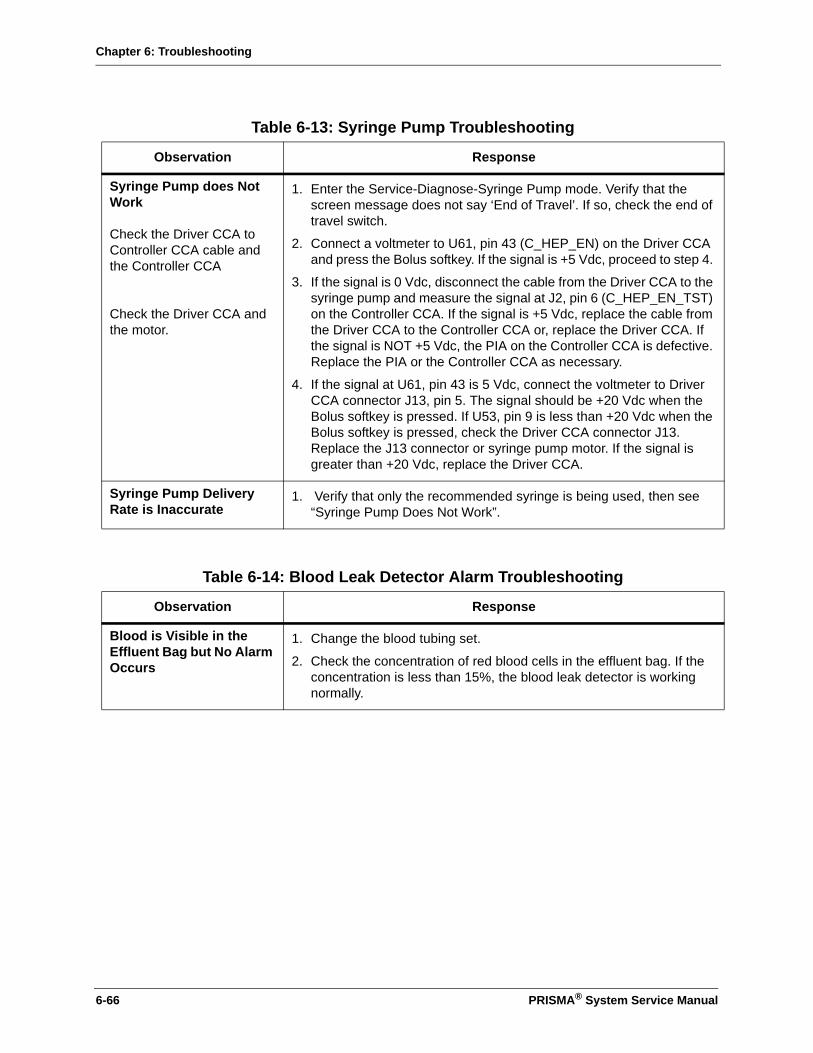
Chapter 6: Troubleshooting
Table 6-13: Syringe Pump Troubleshooting
Observation Response
Syringe Pump does Not Work
Check the Driver CCA to Controller CCA cable and the Controller CCA
Check the Driver CCA and the motor.
1. Enter the Service-Diagnose-Syringe Pump mode. Verify that the screen message does not say ‘End of Travel’. If so, check the end of travel switch.
2. Connect a voltmeter to U61, pin 43 (C_HEP_EN) on the Driver CCA and press the Bolus softkey. If the signal is +5 Vdc, proceed to step 4.
3. If the signal is 0 Vdc, disconnect the cable from the Driver CCA to the syringe pump and measure the signal at J2, pin 6 (C_HEP_EN_TST) on the Controller CCA. If the signal is +5 Vdc, replace the cable from the Driver CCA to the Controller CCA or, replace the Driver CCA. If the signal is NOT +5 Vdc, the PIA on the Controller CCA is defective. Replace the PIA or the Controller CCA as necessary.
4. If the signal at U61, pin 43 is 5 Vdc, connect the voltmeter to Driver CCA connector J13, pin 5. The signal should be +20 Vdc when the Bolus softkey is pressed. If U53, pin 9 is less than +20 Vdc when the Bolus softkey is pressed, check the Driver CCA connector J13. Replace the J13 connector or syringe pump motor. If the signal is greater than +20 Vdc, replace the Driver CCA.
Syringe Pump Delivery Rate is Inaccurate
1. Verify that only the recommended syringe is being used, then see “Syringe Pump Does Not Work”.
Table 6-14: Blood Leak Detector Alarm Troubleshooting
Observation Response
Blood is Visible in the Effluent Bag but No Alarm Occurs
1. Change the blood tubing set.
2. Check the concentration of red blood cells in the effluent bag. If the concentration is less than 15%, the blood leak detector is working normally.
6-66 PRISMA® System Service Manual

Chapter 6: Troubleshooting
Blood Leak Detector Alarm Occurs, No Blood is Observed in the Effluent Bag (and the patient is connected to the machine)
Enter the Service-Diagnose service screen
Check the blood leak detector assembly
1. Verify that the blood tubing set has been properly installed in the blood leak detector housing (press the line into the detector from the bottom up). Adjust the tubing as necessary and press the Override softkey on the Blood Leak Detected screen.
2. If the alarm clears, examine the set for blood clotting conditions and continue with treatment. If the alarm does not clear, check the tubing for liquid or other debris on or in the portion of the tubing that is in the blood leak detector. Clean the tubing according to the instructions in the PRISMA System Operator’s Manual. After cleaning, press Override or Retest as necessary.
3. If the alarm clears, examine the set for blood clotting conditions and continue with treatment. If the alarm does not clear, install a separate fluid-filled piece of tubing in the blood leak detector housing. Press Override.
4. If the alarm clears, examine the set for cleanliness, then reinstall in the detector. Press Override. If the alarm does not remain cleared with the original set, replace the set with a new tubing set.
5. If the alarm continues with the saline-filled tube or with the new tubing set, disconnect the set and remove the machine from service.
6. From the Service-Diagnose service screen, select Blood Leak Detector.
7. Install a fluid-filled piece of tubing in the blood leak detector housing. Press the Normalize softkey on the Blood Leak Detector service screen.
8. If Signal 1 equals Signal 2, check the cable from the blood leak detector to the Detector CCA (J5). If the cable is ok, replace the detector assembly.
Note: After replacing any component, check the normalization of the blood leak detector by using the Blood Leak Detector service screen.
9. If the Difference value is between 167 and 184, press and hold the Self Test softkey and check the Difference value again. If the Difference value is less than or equal to 81, go to step 10. If the Difference value is greater than 81, go to step 11.
10.If the Difference value is less than or equal to 81, there is likely an environmental cause affecting the blood leak detector assembly. Check the detector assembly for foreign objects or residue or, for excessive ambient light (which can cause the detector to normalize to an abnormal value).
Table 6-14: Blood Leak Detector Alarm Troubleshooting (Continued)
Observation Response
PRISMA® System Service Manual 6-67

Chapter 6: Troubleshooting
Check the Detector CCA. 11. If the Difference value is greater than 81, use the up/down arrow keys to make the DAC value on the screen = FF. Connect a voltmeter to the Detector CCA, U16, pin 4. If the voltage does not equal +4.0 Vdc, replace the Detector CCA.
12.If the voltage equals 4.0 Vdc, press and hold the Self Test softkey and verify that the voltage reads 5.0, ± 0.2 Vdc. If the voltage does not equal +5.0 Vdc, replace the Detector CCA. If the voltage equals +5.0, ± 0.2 Vdc, connect the voltmeter to TB 19 on the Detector CCA. Press and hold the Self Test softkey.
13.If the voltage at TB 19 does not equal +1, ±0.1 Vdc, replace the Detector CCA. If the voltage at TB 19 equals +1, ±0.1 Vdc, replace the blood leak detector assembly.
Table 6-15: Display Troubleshooting
Observation Response
Display is Blank(also see Power Supply troubleshooting)
1. Check the cable that carries the video signal from the Monitor CCA to the display. Repair or replace as necessary.
2. Check cable connections for +24 Vdc supply. Replace as necessary.
3. Defective display.
4. Defective Monitor CCA. If you replace the Monitor CCA, see "Restoring Monitor CCA BBRAMs" on page 7-21.
Table 6-16: Power Supply Troubleshooting
Observation Response
Display is Blank and the Fan is Not Operating
1. Check the main power fuses and replace as necessary.
2. If a fuse is replaced and it fails again, disconnect the machine from the power outlet and disconnect the power supply from the Power Distribution CCA. Plug the machine in and turn on the power. If the fuse fails again, check for electrical shorts and replace the power supply if necessary. If the fuse does not fail, the problem is in one of the machine components.
Table 6-14: Blood Leak Detector Alarm Troubleshooting (Continued)
Observation Response
6-68 PRISMA® System Service Manual

Chapter 6: Troubleshooting
One of the Supply Voltages is Not Functioning
1. Turn off the power, disconnect the electrical cord from the outlet, and open the power supply cover.
2. Turn the power on and check the -5, +5, +12 and +24 Vdc power supplies (see page 7-20) and adjust as necessary.
Note: If you adjust the +24 supply, you must check the other supply voltages.
3. If one of the supply voltages is at or near 0 Vdc, turn off the machine. Disconnect the suspected circuit card power cable from the Power Distribution CCA, turn the machine on and check the dc voltages. If the voltage is still at or near 0 Vdc, replace the power supply.
4. Unplug cables from all CCAs to the Power Distribution CCA. Check the supply voltage again. If the voltage returns, reconnect each cable, one at a time while monitoring the supply voltage. Replace the CCA that causes the voltage to drop.
Table 6-17: Alarm Lamp Troubleshooting
Observation Response
One of the Lamps Does Not Illuminate
1. Enter the Service-Diagnose mode, then press the Lights and Tones softkey. Press the Red, Yellow, or Green lamp softkey to turn on a specific lamp. Exchange the non-illuminating lamp with an illuminating lamp to determine if the lamp is defective. Replace lamps as necessary.
2. If the non-illuminating lamp still does not illuminate, turn off the lamp with the Red, Yellow or Green lamp softkey. Using a voltmeter, measure the voltage between the colored wire on the lamp socket and ground. (The colored wire for the red lamp is red, for the yellow lamp is yellow, for the green lamp is green.) If the voltage at the colored wire is not +24 Vdc, the socket is defective.
3. If the voltage at the colored wire is +24 Vdc, turn on the lamp from the Service-Diagnose-Lights and Tones service screen. The voltage should go to 0 Vdc. If the voltage does not go to 0 Vdc, place the voltmeter lead on the Controller CCA test point that corresponds to the lamp being tested.
Green = J2-1, Yellow = J2-2, Red = J2-3
4. Verify the voltage toggles. If the voltage toggles, replace the Driver CCA or U5 (ULN 5706). If the voltage does not toggle, replace the Controller CCA.
Table 6-16: Power Supply Troubleshooting (Continued)
Observation Response
PRISMA® System Service Manual 6-69

Chapter 6: Troubleshooting
None of the Lamps Illuminate
1. Using a voltmeter, check the voltage between the black wire on the lamp socket and ground. If +24 Vdc is present, replace the Driver CCA or IC ULN 5706.
2. If the +24 Vdc is not present, check the black wire for an open connection between the lamp socket and the Driver CCA.
Table 6-18: Audible Alarm Troubleshooting
Observation Response
Audible Alarm is Not Working
1. Enter the Service-Diagnose-Lights and Tones mode and press the Warning Tone softkey.
2. Using a voltmeter, check the voltage at the speaker connector on the Monitor CCA. If the voltage is toggling, replace the speaker
3. If the voltage is not toggling, replace the Monitor CCA or IC LM 386. If you replace the Monitor CCA, see "Restoring Monitor CCA BBRAMs" on page 7-21.
Table 6-17: Alarm Lamp Troubleshooting (Continued)
Observation Response
6-70 PRISMA® System Service Manual
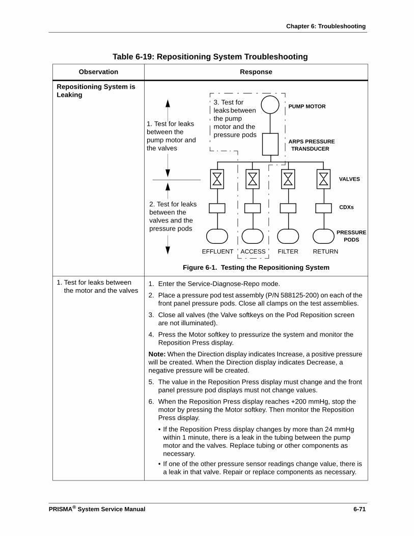
Chapter 6: Troubleshooting
Table 6-19: Repositioning System Troubleshooting
Observation Response
Repositioning System is Leaking
Figure 6-1. Testing the Repositioning System
1. Test for leaks between the motor and the valves
1. Enter the Service-Diagnose-Repo mode.
2. Place a pressure pod test assembly (P/N 588125-200) on each of the front panel pressure pods. Close all clamps on the test assemblies.
3. Close all valves (the Valve softkeys on the Pod Reposition screen are not illuminated).
4. Press the Motor softkey to pressurize the system and monitor the Reposition Press display.
Note: When the Direction display indicates Increase, a positive pressure will be created. When the Direction display indicates Decrease, a negative pressure will be created.
5. The value in the Reposition Press display must change and the front panel pressure pod displays must not change values.
6. When the Reposition Press display reaches +200 mmHg, stop the motor by pressing the Motor softkey. Then monitor the Reposition Press display.
• If the Reposition Press display changes by more than 24 mmHg within 1 minute, there is a leak in the tubing between the pump motor and the valves. Replace tubing or other components as necessary.
• If one of the other pressure sensor readings change value, there is a leak in that valve. Repair or replace components as necessary.
PUMP MOTOR
ARPS PRESSURETRANSDUCER
VALVES
CDXs
PRESSUREPODS
EFFLUENT ACCESS FILTER RETURN
1. Test for leaks between the pump motor and the valves
3. Test for leaks between the pump motor and the pressure pods
2. Test for leaks between the valves and the pressure pods
PRISMA® System Service Manual 6-71

Chapter 6: Troubleshooting
2. Test for leaks between the valves and the pressure pod
1. Enter the Service-Diagnose-Repo mode.
2. Close the particular valve for the pressure circuit to be tested (the valve softkey on the Pod Reposition screen is not illuminated).
3. Attach a syringe and stopcock to the pressure pod test assembly on the front of the machine. Release the appropriate line clamp on the test assembly, pressurize the circuit with the syringe, and close the test assembly line clamp.
Note: The return, filter, and effluent sensors should be pressurized to +250 mmHg, and the access sensor should be pressurized to –250 mmHg. You need to pressurize only the particular valve or pressure circuit under test.
4. Monitor the Pressure display next to the softkey. If the pressure changes by more than 5 mmHg within 1 minute, there is a leak in the tubing between the pressure pod and the valves. Replace tubing or other components as necessary
3. Test for leaks between the motor and the pressure pod
1. Enter the Service-Diagnose-Repo mode.
2. Close all valves except for the particular pressure circuit to be tested (all valve softkeys are not illuminated except the pressure circuit under test).
3. Verify that both clamps are closed on each pod test assembly.
4. Select the proper motor direction and press the Motor softkey to pressurize the system.
Note: When the Direction display indicates Increase, a positive pressure will be created. When the Direction display indicates Decrease, a negative pressure will be created.
5. Stop the motor when the desired pressure is reached. Then, monitor the Pressure display next to the particular valve or pressure circuit under test.
6. If the Pressure display changes by more than 24 mmHg within 1 minute, there is a leak in the tubing between the pump motor and the pressure pod. Replace tubing or other components as necessary.
Table 6-19: Repositioning System Troubleshooting (Continued)
Observation Response
6-72 PRISMA® System Service Manual

Chapter 6: Troubleshooting
A Valve in the Repositioning System is Not Working
1. Enter the Service-Diagnose-Repo mode.
2. Install a pressure test pod assembly. Verify that both clamps are closed on the test assembly.
3. Press the appropriate valve softkey to open the valve. Press the Motor softkey and monitor the Reposition Press and Pressure displays.
4. As the motor runs, the Reposition Press and Pressure display should increase (or decrease, depending on the Motor Direction). If the Pressure display does not increase (or decrease), the appropriate valve is stuck in the closed position.
5. Exchange the electrical connector on the valve that is not working with a valve that is working. If the valve still fails to open after performing steps 1 through 4 again, replace the valve.
6. If the previously working valve now does not work, replace the ARPS CCA.
Reposition System Motor is Not Working
1. Test the motor by pressing the Motor softkey. Verify that the motor shaft rotates and the motor direction changes when requested. If the motor does not rotate, check the motor connector and test again.
2. If the motor still does not rotate, loosen the mounting screws on the ARPS motor and CCA. Disconnect the air line to the valves and gently rotate the assembly until you can access the APRS CCA.
3. Disconnect the motor connector J5. Connect a voltmeter between a proper electrical ground and each of the following pins. You should measure 0.35 Vdc at each pin.
Phase 1 = J5-4Phase 2 = J5-3Phase 3 = J5-2Phase 4 = J5-1
4. If these voltages are present at each pin, replace the motor. If the voltage are not present at each pin, replace the ARPS CCA.
Table 6-19: Repositioning System Troubleshooting (Continued)
Observation Response
PRISMA® System Service Manual 6-73
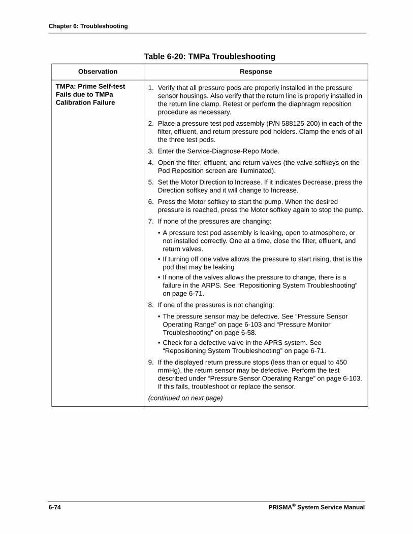
Chapter 6: Troubleshooting
Table 6-20: TMPa Troubleshooting
Observation Response
TMPa: Prime Self-test Fails due to TMPa Calibration Failure
1. Verify that all pressure pods are properly installed in the pressure sensor housings. Also verify that the return line is properly installed in the return line clamp. Retest or perform the diaphragm reposition procedure as necessary.
2. Place a pressure test pod assembly (P/N 588125-200) in each of the filter, effluent, and return pressure pod holders. Clamp the ends of all the three test pods.
3. Enter the Service-Diagnose-Repo Mode.
4. Open the filter, effluent, and return valves (the valve softkeys on the Pod Reposition screen are illuminated).
5. Set the Motor Direction to Increase. If it indicates Decrease, press the Direction softkey and it will change to Increase.
6. Press the Motor softkey to start the pump. When the desired pressure is reached, press the Motor softkey again to stop the pump.
7. If none of the pressures are changing:
• A pressure test pod assembly is leaking, open to atmosphere, or not installed correctly. One at a time, close the filter, effluent, and return valves.
• If turning off one valve allows the pressure to start rising, that is the pod that may be leaking
• If none of the valves allows the pressure to change, there is a failure in the ARPS. See “Repositioning System Troubleshooting” on page 6-71.
8. If one of the pressures is not changing:
• The pressure sensor may be defective. See “Pressure Sensor Operating Range” on page 6-103 and “Pressure Monitor Troubleshooting” on page 6-58.
• Check for a defective valve in the APRS system. See “Repositioning System Troubleshooting” on page 6-71.
9. If the displayed return pressure stops (less than or equal to 450 mmHg), the return sensor may be defective. Perform the test described under “Pressure Sensor Operating Range” on page 6-103. If this fails, troubleshoot or replace the sensor.
(continued on next page)
6-74 PRISMA® System Service Manual
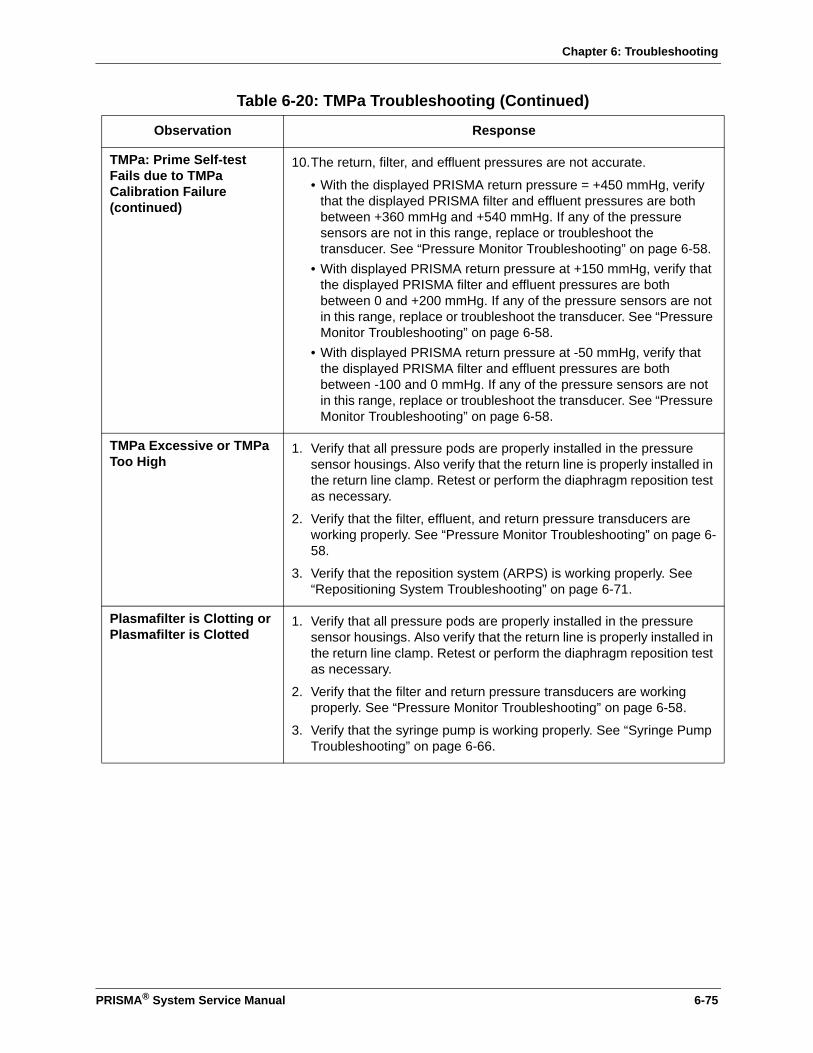
Chapter 6: Troubleshooting
TMPa: Prime Self-test Fails due to TMPa Calibration Failure (continued)
10.The return, filter, and effluent pressures are not accurate.
• With the displayed PRISMA return pressure = +450 mmHg, verify that the displayed PRISMA filter and effluent pressures are both between +360 mmHg and +540 mmHg. If any of the pressure sensors are not in this range, replace or troubleshoot the transducer. See “Pressure Monitor Troubleshooting” on page 6-58.
• With displayed PRISMA return pressure at +150 mmHg, verify that the displayed PRISMA filter and effluent pressures are both between 0 and +200 mmHg. If any of the pressure sensors are not in this range, replace or troubleshoot the transducer. See “Pressure Monitor Troubleshooting” on page 6-58.
• With displayed PRISMA return pressure at -50 mmHg, verify that the displayed PRISMA filter and effluent pressures are both between -100 and 0 mmHg. If any of the pressure sensors are not in this range, replace or troubleshoot the transducer. See “Pressure Monitor Troubleshooting” on page 6-58.
TMPa Excessive or TMPa Too High
1. Verify that all pressure pods are properly installed in the pressure sensor housings. Also verify that the return line is properly installed in the return line clamp. Retest or perform the diaphragm reposition test as necessary.
2. Verify that the filter, effluent, and return pressure transducers are working properly. See “Pressure Monitor Troubleshooting” on page 6-58.
3. Verify that the reposition system (ARPS) is working properly. See “Repositioning System Troubleshooting” on page 6-71.
Plasmafilter is Clotting or Plasmafilter is Clotted
1. Verify that all pressure pods are properly installed in the pressure sensor housings. Also verify that the return line is properly installed in the return line clamp. Retest or perform the diaphragm reposition test as necessary.
2. Verify that the filter and return pressure transducers are working properly. See “Pressure Monitor Troubleshooting” on page 6-58.
3. Verify that the syringe pump is working properly. See “Syringe Pump Troubleshooting” on page 6-66.
Table 6-20: TMPa Troubleshooting (Continued)
Observation Response
PRISMA® System Service Manual 6-75
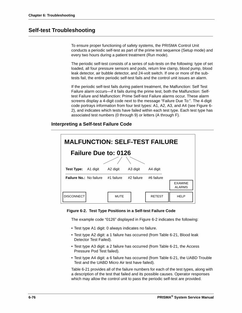
Chapter 6: Troubleshooting
Self-test Troubleshooting
To ensure proper functioning of safety systems, the PRISMA Control Unit conducts a periodic self-test as part of the prime test sequence (Setup mode) and every two hours during a patient treatment (Run mode).
The periodic self-test consists of a series of sub-tests on the following: type of set loaded, all four pressure sensors and pods, return line clamp, blood pump, blood leak detector, air bubble detector, and 24-volt switch. If one or more of the sub-tests fail, the entire periodic self-test fails and the control unit issues an alarm.
If the periodic self-test fails during patient treatment, the Malfunction: Self Test Failure alarm occurs—if it fails during the prime test, both the Malfunction: Self-test Failure and Malfunction: Prime Self-test Failure alarms occur. These alarm screens display a 4-digit code next to the message “Failure Due To:”. The 4-digit code portrays information from four test types: A1, A2, A3, and A4 (see Figure 6-2), and indicates which tests have failed within each test type. Each test type has associated test numbers (0 through 9) or letters (A through F).
Interpreting a Self-test Failure Code
Figure 6-2. Test Type Positions in a Self-test Failure Code
The example code “0126” displayed in Figure 6-2 indicates the following:
• Test type A1 digit: 0 always indicates no failure.
• Test type A2 digit: a 1 failure has occurred (from Table 6-21, Blood leak Detector Test Failed).
• Test type A3 digit: a 2 failure has occurred (from Table 6-21, the Access Pressure Pod Test failed).
• Test type A4 digit: a 6 failure has occurred (from Table 6-21, the UABD Trouble Test and the UABD Micro Air test have failed).
Table 6-21 provides all of the failure numbers for each of the test types, along with a description of the test that failed and its possible causes. Operator responses which may allow the control unit to pass the periodic self-test are provided.
Failure Due to: 0126
A1 digit A2 digit A3 digit A4 digit
MALFUNCTION: SELF-TEST FAILURE
No failure #1 failure #2 failure #6 failure
DISCONNECT MUTE RETEST HELP
EXAMINEALARMS
Test Type:
Failure No.:
6-76 PRISMA® System Service Manual

Chapter 6: Troubleshooting
Table 6-21: Self-test Failure Codes
Test Typeand Failure Numbers Test Failure
Description Possible Cause(s) Operator Response
A1 A2 A3 A4
0 A4: No Failure Exception: 4-digit code 0000
N/AIf 4 digit code is 0000, all periodic self-test attempts were interrupted or failed within the last 6 hours.
N/ANote: For 4-digit code 0000, press Retest. If alarm with code 0000 recurs, end treatment via Disconnect. Troubleshoot the reasons for that self-test interruption or failure.
1 A4: UABD Macro Air Test
1. Return line not installed or improperly installed in air detector.
2. Air bubble in return line due to disconnected line, leaking connection, or incompletely primed set.
3. Air bubble detector is defective
1. Press return line into air detector; press Retest.
2. Remove air via “Return Line” instructions in Air Removal Procedures (at the end of this chapter); press Retest. Note: If air is prevalent in entire set and results in a Malfunction: Prime Test Failure alarm, reprime the set. If air is prevalent in entire set during treatment (Run mode), change the set via Stop.
3. See “Air Bubble Detector Troubleshooting” on page 6-61.
PRISMA® System Service Manual 6-77

Chapter 6: Troubleshooting
2 A4: UABD Trouble Test
1. Return line not installed or improperly installed in air detector.
2. Air bubble in line due to disconnected line, leaking connection, or incompletely primed set.
1. Press return line into air detector; press Retest.
2. Remove air via “Return Line” instructions in Air Removal Procedures (end of this chapter); press Retest.
Note: If air is prevalent in entire set and results in a Malfunction: Prime Test Failure alarm, reprime the set. If air is prevalent in entire set during treatment (Run mode), change the set via Stop. See “Air Bubble Detector Troubleshooting” on page 6-61.
3 A4: numbers 1 and 2
See A4: numbers 1 and 2. See “Air Bubble Detector Troubleshooting” on page 6-61.
4 A4: UABD Micro Air Test
1. Return line not installed or improperly installed in air detector.
2. Air bubble in line due to disconnected line, leaking connection, or incompletely primed set.
3. Air bubble detector is defective.
1. Press return line into air detector; press Retest.
2. Remove air via “Return Line” instructions in Air Removal Procedures (end of this chapter); press Retest.
Note: If air is prevalent in entire set and results in a Malfunction: Prime Test Failure alarm, reprime the set. If air is prevalent in entire set during treatment (Run mode), change the set via Stop.
3. See “Air Bubble Detector Troubleshooting” on page 6-61.
5 A4: numbers 1 and 4
See A4: numbers 1 and 4. See “Air Bubble Detector Troubleshooting” on page 6-61.
Table 6-21: Self-test Failure Codes (Continued)
Test Typeand Failure Numbers Test Failure
Description Possible Cause(s) Operator Response
A1 A2 A3 A4
6-78 PRISMA® System Service Manual

Chapter 6: Troubleshooting
6 A4: numbers 2 and 4
See A4: numbers 2 and 4. See “Air Bubble Detector Troubleshooting” on page 6-61.
7 A4: numbers 1, 2, and 4
See A4: numbers 1, 2, and 4.
See “Air Bubble Detector Troubleshooting” on page 6-61.
8 24-volt Test 24-volt switch latched high or low
1. Press Retest. If alarm does not clear, end treatment via Disconnect.
2. See Table 6-16: “Power Supply Troubleshooting”.
9 A4: numbers 1 and 8
See A4: numbers 1 and 8. See “Air Bubble Detector Troubleshooting” on page 6-61 and Table 6-16: “Power Supply Troubleshooting”.
A A4: numbers 2 and 8
See A4: numbers 2 and 8. See “Air Bubble Detector Troubleshooting” on page 6-61 and Table 6-16: “Power Supply Troubleshooting”.
B A4: numbers 1,2, and 8
See A4: numbers 1,2, and 8.
If the 4-digit code is OOFB and the failure occurs during prime test, additional possible causes are: (1) obstruction not allowing return line clamp to close, then open after the blood leak detector has normalized, (2) defective return line clamp position sensor.
See “Air Bubble Detector Troubleshooting” on page 6-61 and Table 6-16: “Power Supply Troubleshooting”.For 4-digit code OOFB additional causes, remove any obstruction in the return line clamp; press Retest. If alarm with code OOFB recurs, discontinue use. See “Blood Leak Detector Alarm Troubleshooting” on page 6-66 and “Syringe Pump, Line Clamp and Peristaltic Pumps Troubleshooting” on page 6-65.
C A4: numbers 4 and 8
See A4: numbers 4 and 8. See “Air Bubble Detector Troubleshooting” on page 6-61 and Table 6-16: “Power Supply Troubleshooting”.
D A4: numbers 1, 4, and 8
See A4: numbers 1, 4, and 8.
See “Air Bubble Detector Troubleshooting” on page 6-61 and Table 6-16: “Power Supply Troubleshooting”.
Table 6-21: Self-test Failure Codes (Continued)
Test Typeand Failure Numbers Test Failure
Description Possible Cause(s) Operator Response
A1 A2 A3 A4
PRISMA® System Service Manual 6-79
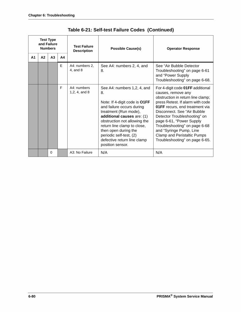
Chapter 6: Troubleshooting
E A4: numbers 2, 4, and 8
See A4: numbers 2, 4, and 8.
See “Air Bubble Detector Troubleshooting” on page 6-61 and “Power Supply Troubleshooting” on page 6-68.
F A4: numbers 1,2, 4, and 8
See A4: numbers 1,2, 4, and 8.
Note: If 4-digit code is O1FF and failure occurs during treatment (Run mode), additional causes are: (1) obstruction not allowing the return line clamp to close, then open during the periodic self-test, (2) defective return line clamp position sensor.
For 4-digit code 01FF additional causes, remove any obstruction in return line clamp; press Retest. If alarm with code 01FF recurs, end treatment via Disconnect. See “Air Bubble Detector Troubleshooting” on page 6-61, “Power Supply Troubleshooting” on page 6-68 and “Syringe Pump, Line Clamp and Peristaltic Pumps Troubleshooting” on page 6-65.
0 A3: No Failure N/A N/A
Table 6-21: Self-test Failure Codes (Continued)
Test Typeand Failure Numbers Test Failure
Description Possible Cause(s) Operator Response
A1 A2 A3 A4
6-80 PRISMA® System Service Manual

Chapter 6: Troubleshooting
1 A3: Return Pressure Pod Test
1. Return pressure pod not installed or improperly installed.
2. Return pressure pod diaphragm out of position.
3. Return line clamped/kinked.
4. Set inadequately primed.
5. Return and/or ARPS pressure sensors not calibrated.
6. Leak in return pod, access site, or return line.
7. Return valve stuck closed; ARPS tubing
leaking/disconnected; return or ARPS valve
installed incorrectly; return or ARPS pressure sensor failed; electronics failure on the analog or ARPS CCAa.
1. Install return pod in its pressure sensor housing; press Retest.
2. Perform the Diaphragm Reposition Procedure (see instructions at end of this chapter); press Retest.
3. Remedy; press Retest.
4. If this cause occurs during the prime test, reprime the set. OR If this cause occurs during treatment, end treatment via Disconnect.
Note: If pressing Retest does not clear the alarm, end treatment via Disconnect.
5. Press Retest.
6. Press Retest.
7. See “Pressure Monitor Troubleshooting” on page 6-58 and “Repositioning System Troubleshooting” on page 6-71.
Table 6-21: Self-test Failure Codes (Continued)
Test Typeand Failure Numbers Test Failure
Description Possible Cause(s) Operator Response
A1 A2 A3 A4
PRISMA® System Service Manual 6-81
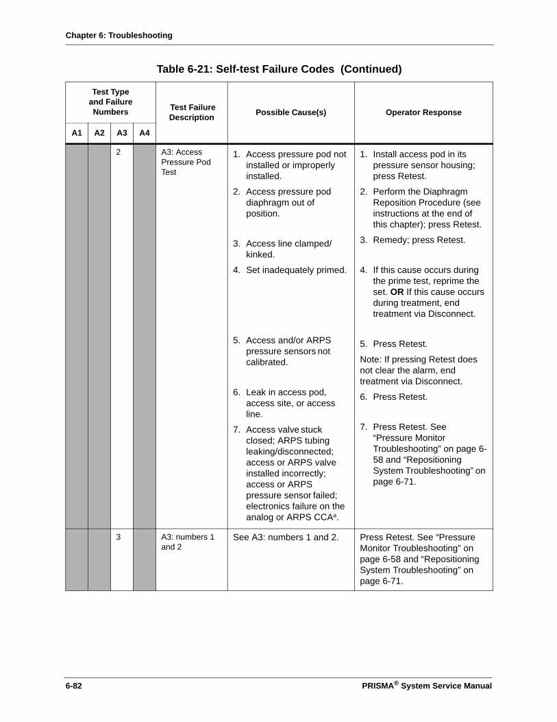
Chapter 6: Troubleshooting
2 A3: Access Pressure Pod Test
1. Access pressure pod not installed or improperly installed.
2. Access pressure pod diaphragm out of position.
3. Access line clamped/kinked.
4. Set inadequately primed.
5. Access and/or ARPS pressure sensors not calibrated.
6. Leak in access pod, access site, or access line.
7. Access valve stuck closed; ARPS tubing
leaking/disconnected; access or ARPS valve
installed incorrectly; access or ARPS pressure sensor failed; electronics failure on the analog or ARPS CCAa.
1. Install access pod in its pressure sensor housing; press Retest.
2. Perform the Diaphragm Reposition Procedure (see instructions at the end of this chapter); press Retest.
3. Remedy; press Retest.
4. If this cause occurs during the prime test, reprime the set. OR If this cause occurs during treatment, end treatment via Disconnect.
5. Press Retest.
Note: If pressing Retest does not clear the alarm, end treatment via Disconnect.
6. Press Retest.
7. Press Retest. See “Pressure Monitor Troubleshooting” on page 6-58 and “Repositioning System Troubleshooting” on page 6-71.
3 A3: numbers 1 and 2
See A3: numbers 1 and 2. Press Retest. See “Pressure Monitor Troubleshooting” on page 6-58 and “Repositioning System Troubleshooting” on page 6-71.
Table 6-21: Self-test Failure Codes (Continued)
Test Typeand Failure Numbers Test Failure
Description Possible Cause(s) Operator Response
A1 A2 A3 A4
6-82 PRISMA® System Service Manual

Chapter 6: Troubleshooting
4 A3: Filter Pressure Pod Test
1. Filter pressure pod not installed or improperly installed.
2. Filter pressure pod diaphragm out of position.
3. Filter line clamped/kinked.
4. Set inadequately primed.
5. Filter and/or ARPS pressure sensors not calibrated.
6. Leak in filter pod, access site, or filter line.
7. Filter valve stuck closed, ARPS tubing leaking/disconnected, filter or ARPS valvea installed incorrectly, filter or ARPS pressure sensor failed, electronics failure on the analog or ARPS CCAa.
1. Install filter pod in its pressure sensor housing; press Retest.
2. Perform the Diaphragm Reposition Procedure (see instructions at the end of this chapter); press Retest.
3. Remedy; press Retest.
4. If this cause occurs during the prime test, reprime the set. OR If this cause occurs during treatment, end treatment via Disconnect.
5. Press Retest.
6. Press Retest.
Note: If pressing Retest does not clear the alarm, end treatment via Disconnect
7. Press Retest. See “Pressure Monitor Troubleshooting” on page 6-58 and “Repositioning System Troubleshooting” on page 6-71.
5 A3: numbers 1 and 4
See A3: numbers 1 and 4. See “Pressure Monitor Troubleshooting” on page 6-58 and “Repositioning System Troubleshooting” on page 6-71.
6 A3: numbers 2 and 4
See A3: numbers 2 and 4. See “Pressure Monitor Troubleshooting” on page 6-58 and “Repositioning System Troubleshooting” on page 6-71.
7 A3: numbers 1, 2, and 4
See A3: numbers 1, 2, and 4.
See “Pressure Monitor Troubleshooting” on page 6-58 and “Repositioning System Troubleshooting” on page 6-71.
Table 6-21: Self-test Failure Codes (Continued)
Test Typeand Failure Numbers Test Failure
Description Possible Cause(s) Operator Response
A1 A2 A3 A4
PRISMA® System Service Manual 6-83

Chapter 6: Troubleshooting
8 A3: Effluent Pressure Pod Test
1. Effluent pressure pod not installed or improperly installed.
2. Effluent pressure pod diaphragm out of position.
3. Effluent line clamped/kinked.
4. Set inadequately primed.
5. Effluent and/or ARPS pressure sensors not calibrated.
6. Leak in effluent pod, access site, or effluent line.
7. Effluent valve stuck closed; ARPS tubing
leaking/disconnected; effluent or ARPS valve
installed incorrectly; effluent or ARPS pressure sensor failed; electronics failure on the analog or ARPS CCAa.
1. Install effluent pod in its pressure sensor housing; press Retest.
2. Perform the Diaphragm Reposition Procedure (see instructions at the end of this chapter); press Retest.
3. Remedy; press Retest.
4. If this cause occurs during the prime test, reprime the set. OR If this cause occurs during treatment, end treatment via Disconnect.
5. Press Retest.
6. Press Retest.
Note: If pressing Retest does not clear the alarm, end treatment via Disconnect.
7. Press Retest. See “Pressure Monitor Troubleshooting” on page 6-58 and “Repositioning System Troubleshooting” on page 6-71.
9 A3: numbers 1 and 8
See A3: numbers 1 and 8. See “Pressure Monitor Troubleshooting” on page 6-58 and “Repositioning System Troubleshooting” on page 6-71.
A A3: numbers 2 and 8
See A3: numbers 2 and 8. See “Pressure Monitor Troubleshooting” on page 6-58 and “Repositioning System Troubleshooting” on page 6-71.
Table 6-21: Self-test Failure Codes (Continued)
Test Typeand Failure Numbers Test Failure
Description Possible Cause(s) Operator Response
A1 A2 A3 A4
6-84 PRISMA® System Service Manual
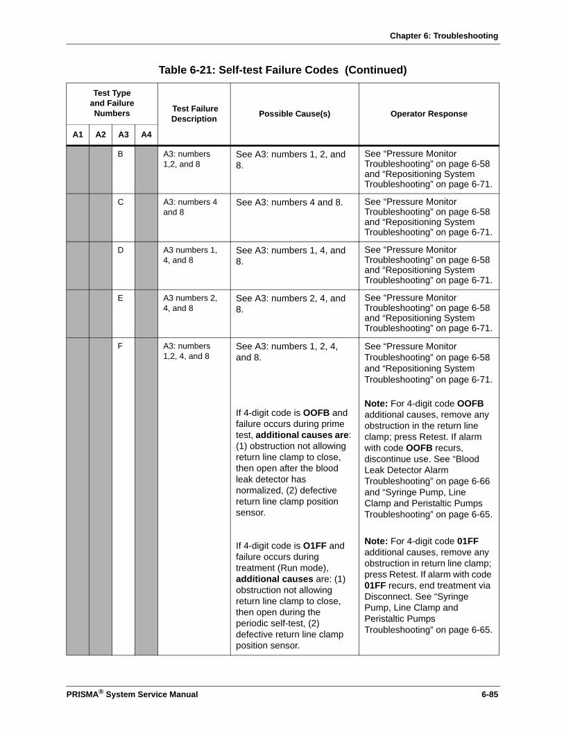
Chapter 6: Troubleshooting
B A3: numbers 1,2, and 8
See A3: numbers 1, 2, and 8.
See “Pressure Monitor Troubleshooting” on page 6-58 and “Repositioning System Troubleshooting” on page 6-71.
C A3: numbers 4 and 8
See A3: numbers 4 and 8. See “Pressure Monitor Troubleshooting” on page 6-58 and “Repositioning System Troubleshooting” on page 6-71.
D A3 numbers 1, 4, and 8
See A3: numbers 1, 4, and 8.
See “Pressure Monitor Troubleshooting” on page 6-58 and “Repositioning System Troubleshooting” on page 6-71.
E A3 numbers 2, 4, and 8
See A3: numbers 2, 4, and 8.
See “Pressure Monitor Troubleshooting” on page 6-58 and “Repositioning System Troubleshooting” on page 6-71.
F A3: numbers 1,2, 4, and 8
See A3: numbers 1, 2, 4, and 8.
If 4-digit code is OOFB and failure occurs during prime test, additional causes are: (1) obstruction not allowing return line clamp to close, then open after the blood leak detector has normalized, (2) defective return line clamp position sensor.
If 4-digit code is O1FF and failure occurs during treatment (Run mode), additional causes are: (1) obstruction not allowing return line clamp to close, then open during the periodic self-test, (2) defective return line clamp position sensor.
See “Pressure Monitor Troubleshooting” on page 6-58 and “Repositioning System Troubleshooting” on page 6-71.
Note: For 4-digit code OOFB additional causes, remove any obstruction in the return line clamp; press Retest. If alarm with code OOFB recurs, discontinue use. See “Blood Leak Detector Alarm Troubleshooting” on page 6-66 and “Syringe Pump, Line Clamp and Peristaltic Pumps Troubleshooting” on page 6-65.
Note: For 4-digit code 01FF additional causes, remove any obstruction in return line clamp; press Retest. If alarm with code 01FF recurs, end treatment via Disconnect. See “Syringe Pump, Line Clamp and Peristaltic Pumps Troubleshooting” on page 6-65.
Table 6-21: Self-test Failure Codes (Continued)
Test Typeand Failure Numbers Test Failure
Description Possible Cause(s) Operator Response
A1 A2 A3 A4
PRISMA® System Service Manual 6-85
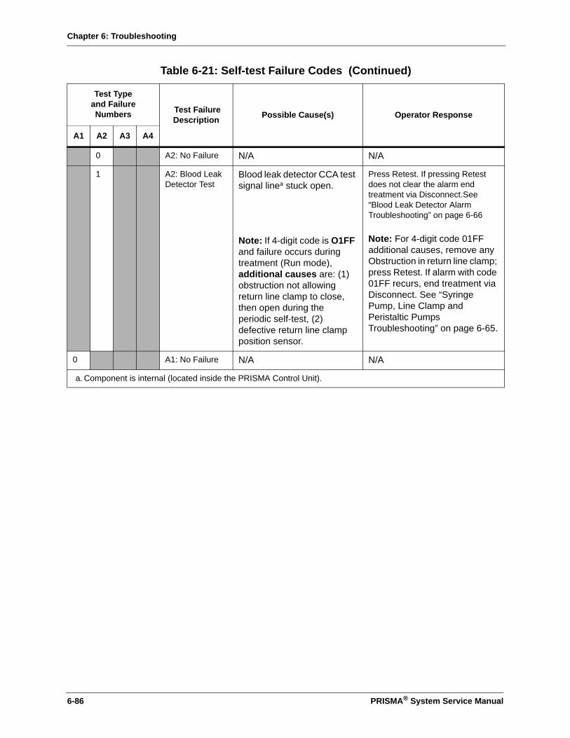
Chapter 6: Troubleshooting
0 A2: No Failure N/A N/A
1 A2: Blood Leak Detector Test
Blood leak detector CCA test signal linea stuck open.
Note: If 4-digit code is O1FF and failure occurs during treatment (Run mode), additional causes are: (1) obstruction not allowing return line clamp to close, then open during the periodic self-test, (2) defective return line clamp position sensor.
Press Retest. If pressing Retest does not clear the alarm end treatment via Disconnect.See “Blood Leak Detector Alarm Troubleshooting” on page 6-66
Note: For 4-digit code 01FF additional causes, remove any Obstruction in return line clamp; press Retest. If alarm with code 01FF recurs, end treatment via Disconnect. See “Syringe Pump, Line Clamp and Peristaltic Pumps Troubleshooting” on page 6-65.
0 A1: No Failure N/A N/A
a. Component is internal (located inside the PRISMA Control Unit).
Table 6-21: Self-test Failure Codes (Continued)
Test Typeand Failure Numbers Test Failure
Description Possible Cause(s) Operator Response
A1 A2 A3 A4
6-86 PRISMA® System Service Manual
Chapter 6: Troubleshooting
Manual Termination of Treatment
The patient’s treatment can be terminated manually at any time. Manual termination may be required due to an alarm, power failure, or other emergency, or when the blood return rate needs to be less than 110 ml/min.
Manual Termination With Blood Return
(See Figure 6-3)
Note: A sterile spike connector may be required.
1. Turn off the power. Clamp the access line (red-striped) and disconnect from the patient. Attach the access line to a 1-liter bag of sterile saline. (Use spike connector, if needed.) Unclamp the access line.
2. Remove the return line (blue-striped) from the return line clamp.
3. Manually turn the blood pump counterclockwise until sufficient blood is returned to the patient.
4. Clamp the return line (blue-striped) and disconnect from the patient. Clamp lines to all bags.
5. Press the clip of the cartridge carrier (left side) to release the cartridge. Starting with any peristaltic pump, manually turn each pump counterclockwise. (The pump segment will work itself out of the pump raceway in a few turns of the rotor. To assist, gently tug on the cartridge assembly while turning a pump.)
6. When the pump segments are free, remove the set and discard as usual.
The alarm system is disabled. Visually check for air in the blood return line until the patient is disconnected.
WARNING
!
PRISMA® System Service Manual 6-87

Chapter 6: Troubleshooting
Figure 6-3. Manually Terminating Treatment (CRRT Set shown)
Manual Termination Without Blood Return
(See Figure 6-3)
Note: The patient will lose the blood contained in the blood flowpath during a manual termination without blood return. For the exact blood volume, see the Instructions for Use packaged with the PRISMA Set.
1. Turn off the power. Clamp the access line (red-striped) and return line (blue-striped) and disconnect from the patient.
2. Clamp lines to all bags.
To manually remove the set from the control unit, press clip of cartridge carrier to release the cartridge. Turn each pump counterclockwise.
Warning: Ensure patient is disconnected from set before removing set from control unit.
B
To manually return the patient’s blood, connect saline to access line, then turn the blood pump counterclockwise by hand.Warning: Watch return line for air.
A
6-88 PRISMA® System Service Manual

Chapter 6: Troubleshooting
3. Press the clip of the cartridge carrier (left side) to release the cartridge. Starting with any peristaltic pump, manually turn each pump counterclockwise. (The pump segment will work itself out of the pump raceway in a few turns of the rotor. To assist, gently tug on the cartridge assembly while turning a pump.)
4. When the pump segments are free, remove the set and discard as usual.
Diaphragm Reposition Procedure
The Diaphragm Reposition procedure can be performed if a pressure pod is accidentally removed after priming is complete, or if an Alarm screen identifies one or more pods as a possible cause of the alarm. The procedure is done separately for each affected pod.
The Reposition Procedure moves the pod diaphragm back to the center of the pod, so that pressure monitoring can again occur. The procedure also clears the pressure sensor housing of any debris that may be preventing a tight seal between the pod and the sensor housing.
The steps of the Diaphragm Reposition Procedure vary, depending on the following factors:
• Type of set in use (PRISMA Set for CRRT or PRISMA TPE Set)
• Exact pressure pod(s) affected
Instructions for performing the proper reposition procedure for the situation at hand are provided below.
Diaphragm Reposition Procedure for CRRT
Note: "Diaphragm Reposition Procedure for TPE" is provided immediately after these instructions.
Supplies Needed
• Isopropyl alcohol and lint-free cloth
• 20-gauge (or smaller diameter) needle attached to a ≤5-cc syringe
• Sterile saline (needed only for access and effluent pods)
• 2 tubing clamps
Access and Effluent Pods (CRRT)
(See Figure 6-4)
Follow the steps below to reposition the diaphragm of the access line pod (near lowest red sample site) or the effluent line pod (near upper yellow sample site).
1. Stop all pumps, then clamp the line below the affected pod and above the sample site of the pod.
Note: Pumps might already be stopped.
PRISMA® System Service Manual 6-89

Chapter 6: Troubleshooting
2. Remove the affected pod from its pressure sensor housing.
Note: Pod might already be removed.
3. Use a lint-free cloth and alcohol to clean the sealing cone inside the sensor housing.
4. Use the needle and syringe to reposition the diaphragm of the affected pod. When the procedure has been completed, resume treatment, or press the appropriate softkey on the Alarm screen.
a. Draw 3 cc saline into the ≤ 5-cc syringe.
b. Inject a maximum of 1 cc of saline into the color-coded sample site between the clamps. (If resistance is felt, remove 1/2 cc volume.)
c. Remove the needle from the sample site. Reinstall the pressure pod in the correct pressure sensor housing and remove the clamps from the line.
d. Resume the treatment.
e. For access pod reposition only: Perform the following test to ensure proper functioning of the access pod. When the control unit is in Run mode, place a clamp on the access line between the access pressure pod and the cartridge. The Warning: Access Pressure Extremely Negative alarm should occur. Unclamp the access line and press the Continue softkey on the Warning screen. Verify that the alarm is cleared (Warning screen leaves the display, green light illuminates).
Filter and Return Pods (CRRT)
(See Figure 6-4)
Follow the steps below to reposition the diaphragm of the filter pod (near upper red sample site) or the return line pod (near blue sample site).
Use aseptic technique when repositioning with needle and syringe.
Injecting more than 1 cc of saline may move the diaphragm beyond the center point of the pod.
If the Warning: Access Pressure Extremely Negative alarm fails to occur, the access pod diaphragm has been repositioned incorrectly. Perform the reposition procedure again.
CAUTION
!
CAUTION
!
WARNING
!
6-90 PRISMA® System Service Manual

Chapter 6: Troubleshooting
1. Stop all pumps, then clamp the line below the affected pod and above the sample site of the pod.
Note: Pumps might already be stopped.
2. Remove the affected pod from its pressure sensor housing.
Note: Pod might already be removed.
3. Use a lint-free cloth and alcohol to clean the sealing cone inside the sensor housing.
4. Use the needle and syringe to reposition the diaphragm of the affected pod. When the procedure has been completed, resume treatment, or press the appropriate softkey on the Alarm screen.
a. Insert the needle with empty syringe into the color-coded sample site between the clamps.
b. Remove a maximum of 1 cc of fluid (if resistance is felt, reinject 1/2 cc).
c. Remove the needle from the sample site. Reinstall the pressure pod in the correct pressure sensor housing and remove the clamps from the line.
d. Resume the treatment.
e. Perform the following test to ensure proper functioning of the pressure pod. When the control unit is in Run mode, place a clamp on the line below the affected pressure pod. An “Extremely Positive” Warning alarm should occur. Unclamp the line and press the Continue softkey on the Warning screen. Verify that the alarm is cleared (Warning screen leaves the display, green light illuminates).
Use aseptic technique when repositioning with needle and syringe.
Removing more than 1 cc of fluid may move the diaphragm beyond the center point of the pod.
If the “Extremely Positive” alarm fails to occur, the pressure pod diaphragm has been repositioned incorrectly. Perform the reposition procedure again.
CAUTION
!
CAUTION
!
WARNING
!
PRISMA® System Service Manual 6-91

Chapter 6: Troubleshooting
Figure 6-4. Repositioning a Pressure Pod
Clean the sealing cone inside the pressure sensor housing.
Inject or remove fluid via the appropriate sample site (Indicated by the arrow in the above figures).Do not pierce the pressure pod.
A
B
6-92 PRISMA® System Service Manual
Chapter 6: Troubleshooting
Diaphragm Reposition Procedure for TPE
Note: "Diaphragm Reposition Procedure for CRRT" is provided immediately before these instructions.
Supplies Needed
• Isopropyl alcohol and lint-free cloth
• 20-gauge (or smaller diameter) needle attached to a ≤5-cc syringe
• Sterile saline (needed only for access and effluent pods)
• 2 tubing clamps
Access Pod (TPE)
(See Figure 6-4)
Follow the steps below to reposition the diaphragm of the access line pod (near lowest red sample site).
1. Stop all pumps, then clamp the line below the access pod and above the sample site of the pod (the pumps might already be stopped).
2. Remove the access pod from its pressure sensor housing.
Note: Pod might already be removed.
3. Use a lint-free cloth and alcohol to clean the sealing cone inside the sensor housing.
4. Use the needle and syringe to reposition the diaphragm of the access pod. When the procedure has been completed, resume treatment, or press the appropriate softkey on the Alarm screen.
a. Draw 3 cc saline into the ≤ 5-cc syringe.
b. Inject a maximum of 1 cc of saline into the color-coded sample site between the clamps. (If resistance is felt, remove 1/2 cc volume.)
c. Remove the needle from the sample site. Reinstall the pressure pod in the correct pressure sensor housing and remove the clamps from the line.
Use aseptic technique when repositioning with needle and syringe.
Injecting more than 1 cc of saline may move the diaphragm beyond the center point of the pod.
CAUTION
!
CAUTION
!
PRISMA® System Service Manual 6-93

Chapter 6: Troubleshooting
d. Resume the treatment.
e. Perform the following test to ensure proper functioning of the access pod. When the control unit is in Run mode, place a clamp on the access line between the access pressure pod and the cartridge. The Warning: Access Pressure Extremely Negative alarm should occur. Unclamp the access line and press the Continue softkey on the Warning screen. Verify that the alarm is cleared (Warning screen leaves the display, green light illuminates).
Filter, Return, and Effluent Pods (TPE)
(See Figure 6-4)
Follow the steps below to reposition the diaphragm of the filter pod (near upper red sample site), the return line pod (near blue sample site), or effluent line pod (near upper yellow sample site).
1. Stop all pumps, then clamp the line below the affected pod and above the sample site of the pod.
Note: Pumps might already be stopped.
2. Remove the affected pod from its pressure sensor housing.
Note: Pod might already be removed.
3. Use a lint-free cloth and alcohol to clean the sealing cone inside the sensor housing.
4. Use the needle and syringe to reposition the diaphragm of the affected pod. When the procedure has been completed, resume treatment, or press the appropriate softkey on the Alarm screen.
a. Insert the needle with empty syringe into the color-coded sample site between the clamps.
If the Warning: Access Pressure Extremely Negative alarm fails to occur, the access pod diaphragm has been repositioned incorrectly. Perform the reposition procedure again.
Use aseptic technique when repositioning with needle and syringe.
WARNING
!
CAUTION
!
6-94 PRISMA® System Service Manual

Chapter 6: Troubleshooting
PRISMA® System Service Manual 6-95
b. Remove a maximum of 1 cc of fluid (if resistance is felt, reinject 1/2 cc).
c. Remove the needle from the sample site. Reinstall the pressure pod in the correct pressure sensor housing and remove the clamps from the line.
d. Resume the treatment.
e. For filter and return pod reposition: Perform the following test to ensure proper functioning of the affected pressure pod. When the control unit is in Run mode, place a clamp on the line below the pressure pod. An “Extremely Positive” Warning alarm should occur. Unclamp the line and press the Continue softkey on the Warning screen. Verify that the alarm is cleared (Warning screen leaves the display, green light illuminates).
f. For effluent pod reposition: Perform the following test to ensure proper functioning of the effluent pod. When the control unit is in Run mode, place a clamp on the effluent line between the effluent pressure pod and the cartridge. The Caution: Effluent Pressure Too Negative alarm should occur. Unclamp the effluent line and press the Continue softkey on the Caution screen. Verify that the alarm is cleared (Caution screen leaves the display, green light illuminates).
Air Removal Procedures for All Therapies
Air is normally removed from the set during the automatic priming cycle; however, small bubbles may become trapped in the filter header or pressure pods. These can be removed via the sample sites in the set lines.
Note: Air removal procedures are the same, regardless of whether a PRISMA Set for CRRT or a PRISMA TPE Set is in use. The instructions below apply to both types of sets.
Note: If air occurs in the return line during treatment, a Warning alarm occurs. Air removal instructions are provided on the Warning screen, as well as here under
Removing more than 1 cc of fluid may move the diaphragm beyond the center point of the pod.
If the “Extremely Positive” alarm fails to occur, the pressure pod diaphragm has been repositioned incorrectly. Perform the reposition procedure again.
If the Caution: Effluent Pressure Too Negative alarm fails to occur, the effluent pod diaphragm has been repositioned incorrectly. Perform the reposition procedure again.
CAUTION
!
WARNING
!
WARNING
!

Chapter 6: Troubleshooting
“Return Line During Air in Blood Alarm.”
Supplies Needed
20-gauge (or smaller diameter) needle attached to a ≤ 5-cc syringe tubing clamp
Access Pressure Pod
1. Ensure that all peristaltic pumps are stopped. Clamp the access line (red-striped) at cartridge.
2. Insert the 20-gauge needle with syringe into the lower red sample site and aspirate air/blood until the air is removed or resistance is felt.
3. Remove the needle; unclamp the access line.
Return Pressure Pod
1. Ensure that all peristaltic pumps are stopped. Clamp the return line (blue-striped) at cartridge.
a. Insert the 20-gauge needle with syringe into the blue sample site and aspirate air/blood until the air is removed or resistance is felt.
b. Remove the needle; unclamp the return line.
Effluent Pressure Pod
1. Ensure that all peristaltic pumps are stopped.
2. Insert the 20-gauge needle with syringe into the upper yellow sample site and aspirate air/effluent until the air is removed or resistance is felt. Remove the needle.
Filter Pressure Pod/Filter Header
1. Ensure that all peristaltic pumps are stopped.
2. Insert the 20-gauge needle with syringe into the upper red sample site closest to the filter pod (to remove air from pod) or into the upper red sample site nearest the filter header (to remove air from header). Aspirate air/blood until the air is removed or resistance is felt. Remove the needle.
6-96 PRISMA® System Service Manual

Chapter 6: Troubleshooting
Return Line During Air in Blood Alarm
(See Figure 6-5)
1. Clamp the return line (blue-striped) at the cartridge.
2. Insert the 20-gauge needle with syringe into the blue sample site and aspirate air/blood until the return pressure displays a negative number on the Warning screen.
3. Remove the needle; pull the return clamp open.
4. Repeat until all air is removed, then unclamp the return line and press Continue from the Alarm screen.
Figure 6-5. Removing Air From the Return Line
A Aspirate air/blood via blue sample site. B Pull return clamp open.
PRISMA® System Service Manual 6-97

Chapter 6: Troubleshooting
Component Operation Verification Procedures
During troubleshooting and/or repair work on the machine it may sometimes be advantageous to test the machine for specific levels of operation. The following procedures are provided to help the technician test the machine to verify that it is operating within published specification limits.
Syringe Pump Accuracy
1. Get a piece of masking tape or cloth tape about 6 inches long.
2. Apply the tape to the front panel next to the heparin syringe. The tape should be as close as possible to the syringe holder so that it is actually behind the moving carriage.
3. Load a 20 cc heparin syringe into syringe holder. Adjust the plunger so that it is approximately on the 20 cc mark of the syringe barrel.
4. Raise the heparin carriage until it touches the syringe plunger. Move the plunger lock lever to the left to lock around the plunger.
5. Turn on the machine and enter the SERVICE-DIAGNOSE-SYRINGE PUMP screen.
6. Press the BOLUS softkey to take up the slack in the pump mechanism.
7. Once the bolus is complete, use a pen to mark the heparin carriage position on the tape.
8. Select the ADJUST RATE softkey.
9. Use arrow keys to set rate to 20.0 ml/hr.
10. Press the CONTINUOUS softkey and immediately start a stop watch.
11. After 30 minutes press the STOP softkey. Use a pen to mark the heparin carriage position on the tape.
12. Measure the distance between the two pen marks. It may be necessary to move the heparin syringe carriage up or down to get a measurement.
13. The 2 lines should be 30.3 mm to 37 mm apart. A measurement outside of this range indicates that the heparin pump is not pumping accurately.
Syringe Pump Bolus Volume and Delivery Rate
1. Enter the SERVICE-DIAGNOSE mode.
2. Install a syringe into the syringe pump and adjust the volume to 6cc.
3. Monitor the voltage on the HEPEN testpoint on the controller CCA.
6-98 PRISMA® System Service Manual

Chapter 6: Troubleshooting
4. Press SYRINGE PUMP. Start a stopwatch and press BOLUS at the same time.
5. Verify HEPEN test point changes from HIGH to LOW in less than or equal to 100 seconds.
6. Verify the pump motor stops turning.
7. Verify the plunger moved up 5cc.
8. Press EXIT.
Pump Flow Rate Ranges
1. Enter the SERVICE-DIAGNOSE mode.
2. Press PUMPS. Set the pumps to the following speeds in the clockwise direction:
Replacement pump 2 rpmEffluent pump 2 rpmDialysate pump 2 rpmBlood pump 2 rpm
3. Verify that tach values agree.
4. Change the direction for each pump and set the pumps to the following speeds:
Replacement pump 30 rpm Effluent pump 83 rpm Dialysate pump 38 rpm Blood pump 222 rpm
5. Verify that the tach values agree with the commanded values, within the given tolerance, and the direction has changed.
6. Press Exit.
Pump Flow Rate Accuracy
Note: During the following tests, the Access and Return lines should be placed in a 500 ml or larger container filled with water.
Blood Pump
1. Turn on machine and select NEW PATIENT, CONTINUE, SCUF.
2. Load PRISMA tubing set as instructed on the screens, except that the Access and Return lines may be placed in a container with at least 500 ml of water for priming instead of using a bag of priming solution and a prime collection bag.
3. Prime Tubing set. When priming is complete, remove the Return line from the
PRISMA® System Service Manual 6-99

Chapter 6: Troubleshooting
Return Clamp and turn off machine.
4. Turn the machine on in the Service mode and weigh an empty PRISMA 5-Liter bag in SERVICE-DIAGNOSE-SCALES mode using Replacement scale and record the weight.
5. Hang the empty bag on the right corner bag hook. Connect the bag to the Return line. Leave the Access line in a 500 ml or larger container filled with water.
6. In SERVICE-DIAGNOSE-PUMPS mode, press the 24 VOLT softkey until it indicates the 24 Volts is OFF, then set Blood pump rate to 100 ml/min and change the direction to CCW.
7. Simultaneously press the 24 VOLT softkey so that it indicates ON, and start a stopwatch.
8. Run the pump for 7 min., adding more fluid to the 500 ml container as needed, then press the 24 VOLT softkey to turn the pump off.
9. Enter SERVICE-DIAGNOSE-SCALES screen.
10. Clamp the line on the collection bag, then disconnect bag from Access line and weigh on Effluent scale.
11. Weight should be 700 g, ±44 g, greater than the weight recorded in Step 4.
Effluent Pump
1. Turn on machine and select NEW PATIENT, CONTINUE, SCUF.
2. Load PRISMA tubing set as instructed on the screens, except that the Access and Return lines may be placed in a container with at least 500 ml of water for priming instead of using a bag of priming solution and a prime collection bag.
3. Prime Tubing set. When priming is complete, turn off machine.
4. Turn the machine on in the Service mode. Clamp the Effluent bag, disconnect it from the tubing set, and weigh the effluent bag in SERVICE-DIAGNOSE-SCALES mode using the Replacement scale. Record the weight.
5. Turn off the machine and reconnect the Effluent bag to the Effluent line and unclamp the bag.
6. Turn on the machine. From the CHOOSE PATIENT screen go into TEST mode, then choose SAME PATIENT.
7. Press LOAD, then skip Load by pressing the OVERRIDE softkey. Press CONTINUE on the PREPARE SOLUTIONS screen, then press PRIME from the CONNECT LINES TO SOLUTIONS screen. Immediately press OVERRIDE to skip Prime.
8. At the Prime Complete screen, press CONTINUE to perform the Prime Test.
9. After Prime Test has passed, select CONTINUE, then enter pump speed for fluid removal rate of 500 ml/hr. Select CONTINUE.
6-100 PRISMA® System Service Manual
Chapter 6: Troubleshooting
10. Follow the directions to Connect Patient, but leave the Return and Access lines in the container of water. Make sure the container has at least 500 ml of fluid in it.
11. Press START softkey and immediately start a stopwatch.
12. Run for 2 hours, 30 minutes, adding more fluid to the 500 ml container as needed, then press STOP from the STATUS screen. Override any RETURN DISCONNECTION CANNOT BE DETECTED and ACCESS DISCONNECTION CANNOT BE DETECTED alarms immediately when they occur.
13. Turn off machine, then turn it back on in the Service mode and enter SERVICE-DIAGNOSE-SCALES screen.
14. Clamp the Effluent bag line and disconnect bag from Effluent line. Weigh it on the Replacement scale.
15. Weight should be 1250 g, ±57 g, greater than the weight recorded in Step 4.
Dialysate Pump
1. Turn on machine and select NEW PATIENT, CONTINUE, CVVHD.
2. Load PRISMA tubing set as instructed on the screens, except that the Access and Return lines may be placed in a container with at least 500 ml of water for priming instead of using a bag of priming solution and a prime collection bag.
3. Prime Tubing set. You will need an empty Effluent bag and a 5 Liter bag with approximately 2500 ml of water in it to use as the Dialysate bag. When priming is complete, turn off machine.
4. Turn the machine on in the Service mode. Clamp the Dialysate bag, disconnect it from the tubing set, and weigh the Dialysate bag in SERVICE-DIAGNOSE-SCALES mode using the Replacement scale. Record the weight.
5. Turn off the machine and reconnect the Dialysate bag to the Dialysate line and unclamp the bag.
6. Turn on the machine. From the CHOOSE PATIENT screen go into TEST mode, then choose SAME PATIENT.
7. Press LOAD, then skip Load by pressing the OVERRIDE softkey. Press CONTINUE on the PREPARE SOLUTIONS screen, then press PRIME from the CONNECT LINES TO SOLUTIONS screen. Immediately press OVERRIDE to skip Prime.
8. At the Prime Complete screen, press CONTINUE to perform the Prime Test.
9. After Prime test has passed, select CONTINUE, then enter pump speeds for Dialysate pump rate to 2500 ml/hr, and fluid removal rate to 0 ml/hr. Select CONTINUE.
10. Follow the directions to Connect Patient, but leave the Return and Access lines in the container of water. Make sure the container has at least 500 ml of fluid in it.
PRISMA® System Service Manual 6-101
Chapter 6: Troubleshooting
11. Press START softkey and immediately start a stopwatch.
12. Run for 30 minutes, then press STOP from the STATUS screen. Override any RETURN DISCONNECTION CANNOT BE DETECTED and ACCESS DISCONNECTION CANNOT BE DETECTED alarms immediately when they occur.
13. Turn off machine, then turn it back on in the Service mode and enter SERVICE-DIAGNOSE-SCALES screen.
14. Clamp the Dialysate bag line and disconnect bag from Dialysate line. Weigh it on the Replacement scale.
15. Weight should be 1250 g, ±105 g, less than the weight recorded in Step 4.
Replacement Pump
1. Turn on machine and select NEW PATIENT, CONTINUE, CVVH.
2. Load PRISMA tubing set as instructed on the screens, except that the Access and Return lines may be placed in a container with at least 500 ml of water for priming instead of using a bag of priming solution and a prime collection bag.
3. Prime Tubing set. You will need an empty Effluent bag and a 5 Liter bag with approximately 2500 ml of water in it to use as the Replacement bag. When priming is complete, turn off machine.
4. Turn the machine on in the Service mode. Clamp the Replacement bag, disconnect it from the tubing set, and weigh the Replacement bag in SERVICE-DIAGNOSE-SCALES mode using the Dialysate scale. Record the weight.
5. Turn off the machine and reconnect the Replacement bag to the Replacement line and unclamp the bag.
6. Turn on the machine. From the CHOOSE PATIENT screen go into TEST mode, then choose SAME PATIENT.
7. Press LOAD, then skip Load by pressing the OVERRIDE softkey. Press CONTINUE on the PREPARE SOLUTIONS screen, then press PRIME from the CONNECT LINES TO SOLUTIONS screen. Immediately press OVERRIDE to skip Prime.
8. At the Prime Complete screen, press CONTINUE to perform the Prime Test.
9. After Prime test has passed, select CONTINUE, then enter pump speeds for Replacement pump rate to 2000 ml/hr, and fluid removal rate to 0 ml/hr. Select CONTINUE.
10. Follow the directions to Connect Patient, but leave the Return and Access lines in the container of water. Make sure the container has at least 500 ml of fluid in it.
11. Press START softkey and immediately start a stopwatch.
12. Run for 30 minutes, then press STOP from the STATUS screen. Override any
6-102 PRISMA® System Service Manual
Chapter 6: Troubleshooting
RETURN DISCONNECTION CANNOT BE DETECTED and ACCESS DISCONNECTION CANNOT BE DETECTED alarms immediately when they occur.
13. Turn off machine, then turn it back on in the Service mode and enter SERVICE-DIAGNOSE-SCALES screen.
14. Clamp the Replacement bag line and disconnect bag from Replacement line. Weigh it on the Dialysate scale.
15. Weight should be 1000 g, ±68 g, less than the weight recorded in Step 4.
Audible Alarm
1. Enter the SERVICE-DIAGNOSE mode.
2. Press WARNING TONE. Verify continuous beeping tone sounds.
3. Press MALF. TONE. Verify continuous beeping tone sounds.
4. Press CAUTION TONE. Verify intermittent double beep tone sounds.
5. Press ADVISORY TONE. Verify intermittent single beep tone sounds.
6. Press EXIT.
Pressure Sensor Operating Range
Note: When setting pressures in this section, use a pressure meter as the reference. Use the test pressure pods with one end attached to a calibrated pressure meter and the other end attached to a syringe which will be used to apply the pressures.
1. Enter the SERVICE-DIAGNOSE mode.
2. Press PRESSURES.
3. With the pressure pods exposed to atmospheric pressure, verify the average readings are 0.
4. Install a test pressure pod in each of the pressure pod holders.
5. Apply -50 mmHg pressure to filter and return pressure sensors. Verify each is within 8 mmHg of the pressure meter.
6. Apply +100 mmHg pressure to filter and return pressure sensors. Verify each is within 10 mmHg of the pressure meter. Clamp the line from the syringe for 60 seconds and verify the pressure decrease is less than 4 mmHg.
7. Apply +500 mmHg pressure to the filter pressure sensor. Verify it is within 50 mmHg of the pressure meter.
8. Apply +350 mmHg pressure to the return pressure sensor. Verify it is within 35 mmHg of the pressure meter.
PRISMA® System Service Manual 6-103
Chapter 6: Troubleshooting
9. Apply +50 mmHg pressure to effluent and access pressure sensors. Verify each is within 8 mmHg of the pressure meter.
10. Apply -100 mmHg pressure to effluent and access pressure sensors. Verify it is within 10 mmHg of the pressure meter. Clamp the line from the syringe for 60 seconds verify the pressure increase is less than 4 mmHg.
11. Apply -250 mmHg pressure to the access pressure sensor. Verify it is within 25 mmHg of the pressure meter.
12. Apply -350 mmHg pressure to the effluent pressure sensor. Verify it is within 35 mmHg of the pressure meter.
13. Apply +100 mmHg to the effluent pressure sensor. Verify it is within 13 mmHg of the pressure meter. Clamp the line from the syringe for 60 seconds and verify the pressure decrease is less than 4 mmHg.
14. Apply +350 mmHg to the effluent pressure sensor. Verify it is within 46 mmHg of the pressure meter.
15. Apply positive pressure to the effluent sensor and verify that the PRISMA can display +400 mmHg average effluent pressure.
16. Apply positive pressure to the return sensor and verify that the PRISMA can display +450 mmHg average effluent pressure.
17. Apply positive pressure to the filter sensor and verify that the PRISMA can display +500 mmHg average filter pressure.
Pressure Sensor Alarms
Note: For all pressure alarm tests, the applied pressure represents the alarm limit plus the tolerance of 8 mmHg or 10%, whichever is greater.
1. Cycle power to the machine. From the ‘Choose Patient’ screen, enter Test Mode by pressing softkeys A, B, C, D, in that order. See “Test Mode Screen” on page 5-24 for Test Mode softkey arrangement.
2. Press NEW PATIENT, CONTINUE, and SCUF.
3. Load a PRISMA Set for CRRT (either predilution or postdilution) as instructed on the screens, except that the access and return lines may be placed in a container with at least 500 ml of water for priming instead of using a bag of priming solution and a prime collection bag. If the tubing set is already loaded from earlier testing, you may OVERRIDE the load.
4. Install a water filled tube into the UABD and BLD housings.
5. Clamp the heparin line with the slide clamp because the heparin line cap is vented.
6. Prime the tubing set. You will need an empty Effluent bag. If the tubing set is already completely primed from earlier testing, you may OVERRIDE the prime.
6-104 PRISMA® System Service Manual

Chapter 6: Troubleshooting
7. At the PRIME COMPLETE screen, press CONTINUE to perform prime test.
8. Advance through the screens to the Set Flow Rates screen.
9. From the Set Flow Rates screen, verify the Fluid Removal Rate is 0 mL/hr, the Blood Flow Rate is 100 mL/min, and the Anticoag Flow Rate is set for Continuous flow at 0 mL/hr. Press CONTINUE twice to advance to the Connect Patient Screen.
10. Apply the following pressures to the pressure pods and clamp:
Access -50 mmHgEffluent -50 mmHgFilter 100 mmHgReturn 50 mmHg
11. Press START and allow the machine to complete the self-test.
12. Override any pressure related alarms and repressurize the pressure pods to the values listed above.
Access Line Pressure Sensor
1. Press STOP, then RESUME with the pressures still applied. Allow the system time to set an operating point, at least 2 minutes.
2. Apply a pressure of -110 mmHg to the access pressure sensor. Verify the ADVISORY: ACCESS TOO NEGATIVE alarm occurs, the yellow status light is lit, and the audible alarm occurs. Override the alarm.
3. Press STOP, then RESUME with the -110 mmHg still applied. Allow the system time to set an operating point, at least 2 minutes.
4. Apply -50 mmHg to the access pressure sensor. Verify that an ADVISORY: ACCESS PRESSURE (Access Pressure is Rising) alarm occurs, the yellow status light is lit, and the audible alarm occurs. Clear the alarm.
5. Slowly apply -275 mmHg to the access pressure sensor. Verify that an WARNING: ACCESS PRESSURE EXTREMELY NEGATIVE alarm occurs, the pumps stop, the return line is clamped, the red status light is lit, and the audible alarm occurs. Clear the alarm by increasing the pressure to -50 mmHg and pressing CONTINUE. Wait at least 2 minutes.
6. Apply -2 mmHg to the access pressure sensor. Verify that an WARNING: ACCESS DISCONNECTION alarm occurs, the pumps stop, the return line is clamped, the red status light is lit, and the audible alarm occurs. Clear the alarm.
7. Apply -50 mmHg to the access pressure pod.
PRISMA® System Service Manual 6-105
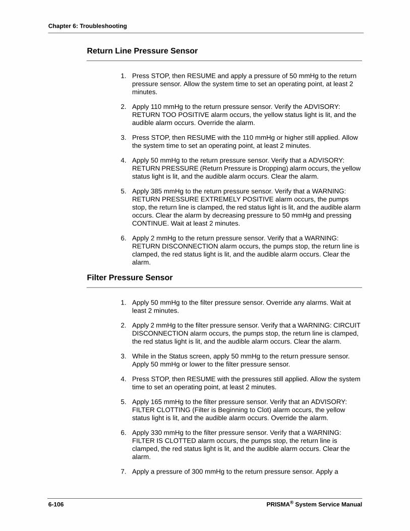
Chapter 6: Troubleshooting
Return Line Pressure Sensor
1. Press STOP, then RESUME and apply a pressure of 50 mmHg to the return pressure sensor. Allow the system time to set an operating point, at least 2 minutes.
2. Apply 110 mmHg to the return pressure sensor. Verify the ADVISORY: RETURN TOO POSITIVE alarm occurs, the yellow status light is lit, and the audible alarm occurs. Override the alarm.
3. Press STOP, then RESUME with the 110 mmHg or higher still applied. Allow the system time to set an operating point, at least 2 minutes.
4. Apply 50 mmHg to the return pressure sensor. Verify that a ADVISORY: RETURN PRESSURE (Return Pressure is Dropping) alarm occurs, the yellow status light is lit, and the audible alarm occurs. Clear the alarm.
5. Apply 385 mmHg to the return pressure sensor. Verify that a WARNING: RETURN PRESSURE EXTREMELY POSITIVE alarm occurs, the pumps stop, the return line is clamped, the red status light is lit, and the audible alarm occurs. Clear the alarm by decreasing pressure to 50 mmHg and pressing CONTINUE. Wait at least 2 minutes.
6. Apply 2 mmHg to the return pressure sensor. Verify that a WARNING: RETURN DISCONNECTION alarm occurs, the pumps stop, the return line is clamped, the red status light is lit, and the audible alarm occurs. Clear the alarm.
Filter Pressure Sensor
1. Apply 50 mmHg to the filter pressure sensor. Override any alarms. Wait at least 2 minutes.
2. Apply 2 mmHg to the filter pressure sensor. Verify that a WARNING: CIRCUIT DISCONNECTION alarm occurs, the pumps stop, the return line is clamped, the red status light is lit, and the audible alarm occurs. Clear the alarm.
3. While in the Status screen, apply 50 mmHg to the return pressure sensor. Apply 50 mmHg or lower to the filter pressure sensor.
4. Press STOP, then RESUME with the pressures still applied. Allow the system time to set an operating point, at least 2 minutes.
5. Apply 165 mmHg to the filter pressure sensor. Verify that an ADVISORY: FILTER CLOTTING (Filter is Beginning to Clot) alarm occurs, the yellow status light is lit, and the audible alarm occurs. Override the alarm.
6. Apply 330 mmHg to the filter pressure sensor. Verify that a WARNING: FILTER IS CLOTTED alarm occurs, the pumps stop, the return line is clamped, the red status light is lit, and the audible alarm occurs. Clear the alarm.
7. Apply a pressure of 300 mmHg to the return pressure sensor. Apply a
6-106 PRISMA® System Service Manual

Chapter 6: Troubleshooting
pressure of 550 mmHg to the filter pressure sensor. Verify the WARNING: FILTER PRESSURE EXTREMELY POSITIVE alarm occurs.
TMP Alarms
1. Cycle power to the machine and press RESTART twice to advance to the Choose Patient screen.
2. From the ‘Choose Patient’ screen, enter Test Mode by pressing softkeys 1, 3, 12, 2 in that order.
3. Press NEW PATIENT, CONTINUE, and SCUF. Press LOAD then OVERRIDE.
4. Install a water filled tube in the UABD and BLD housings. Install a 20 cc syringe in the syringe pump.
5. Advance through the screens to the Set Flow Rates screen (press OVERRIDE from the Prime screen to bypass priming).
6. From the Set Flow Rates screen, verify the Fluid Removal Rate is 0 mL/hr, the Blood Flow Rate is 100 mL/min, and the Anticoag Flow Rate is set for Continuous flow at 0 mL/hr. Press CONTINUE twice to advance to the Connect Patient Screen.
7. Apply the following pressures to the pressure pods and clamp:
Access -50 mmHgEffluent -150 mmHgFilter 150 mmHgReturn 150 mmHg
8. Allow the system time to set an operating point, at least 2 minutes.
9. Apply a pressure of -235 mmHg to the effluent pressure sensor. Verify ADVISORY: TMP TOO HIGH alarm occurs.
10. With the pressure still applied to all pressure sensors, power cycle the machine then press CONTINUE.
11. With the pressure still applied to the return and filter pressure sensors, apply a pressure of -345 mmHg to the effluent pressure sensor. Verify that the CAUTION: TMP EXCESSIVE alarm occurs.
PRISMA® System Service Manual 6-107
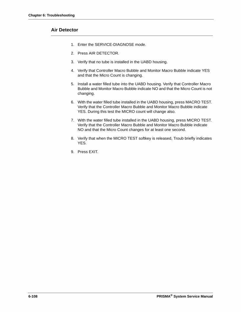
Chapter 6: Troubleshooting
Air Detector
1. Enter the SERVICE-DIAGNOSE mode.
2. Press AIR DETECTOR.
3. Verify that no tube is installed in the UABD housing.
4. Verify that Controller Macro Bubble and Monitor Macro Bubble indicate YES and that the Micro Count is changing.
5. Install a water filled tube into the UABD housing. Verify that Controller Macro Bubble and Monitor Macro Bubble indicate NO and that the Micro Count is not changing.
6. With the water filled tube installed in the UABD housing, press MACRO TEST. Verify that the Controller Macro Bubble and Monitor Macro Bubble indicate YES. During this test the MICRO count will change also.
7. With the water filled tube installed in the UABD housing, press MICRO TEST. Verify that the Controller Macro Bubble and Monitor Macro Bubble indicate NO and that the Micro Count changes for at least one second.
8. Verify that when the MICRO TEST softkey is released, Troub briefly indicates YES.
9. Press EXIT.
6-108 PRISMA® System Service Manual
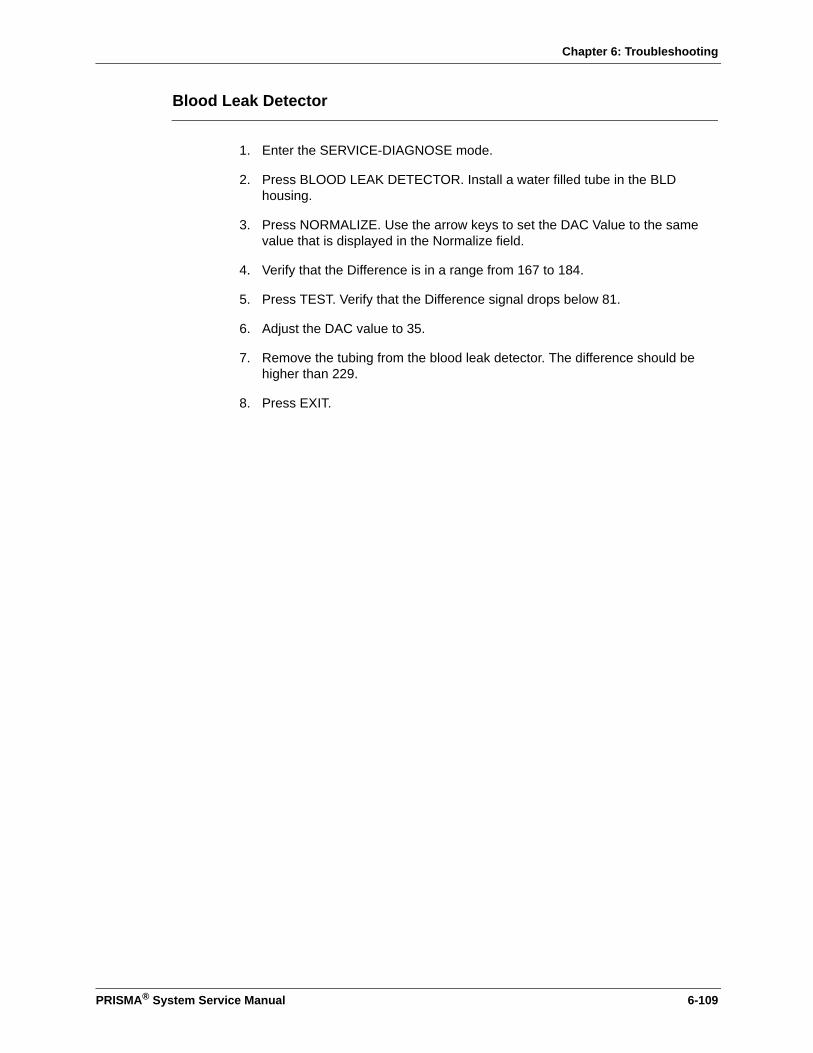
Chapter 6: Troubleshooting
Blood Leak Detector
1. Enter the SERVICE-DIAGNOSE mode.
2. Press BLOOD LEAK DETECTOR. Install a water filled tube in the BLD housing.
3. Press NORMALIZE. Use the arrow keys to set the DAC Value to the same value that is displayed in the Normalize field.
4. Verify that the Difference is in a range from 167 to 184.
5. Press TEST. Verify that the Difference signal drops below 81.
6. Adjust the DAC value to 35.
7. Remove the tubing from the blood leak detector. The difference should be higher than 229.
8. Press EXIT.
PRISMA® System Service Manual 6-109

Chapter 6: Troubleshooting
6-110 PRISMA® System Service Manual
This page is left intentionally blank
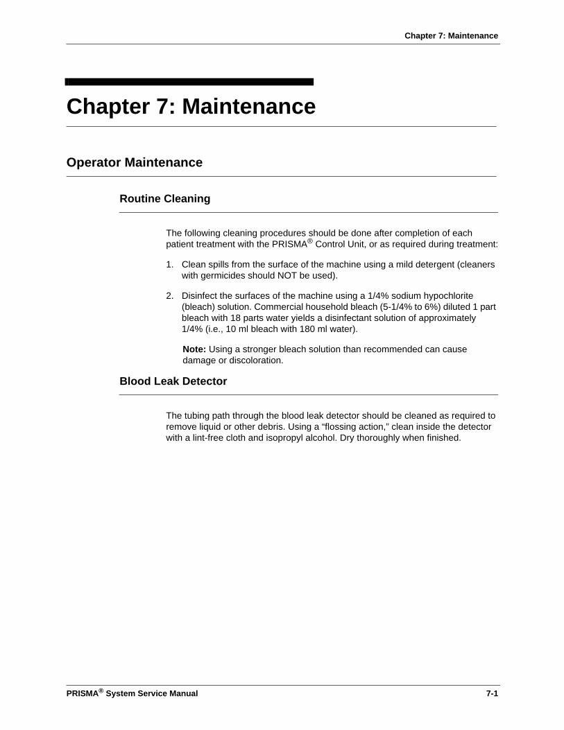
Chapter 7: Maintenance
Chapter 7: Maintenance
Operator Maintenance
Routine Cleaning
The following cleaning procedures should be done after completion of each patient treatment with the PRISMA® Control Unit, or as required during treatment:
1. Clean spills from the surface of the machine using a mild detergent (cleaners with germicides should NOT be used).
2. Disinfect the surfaces of the machine using a 1/4% sodium hypochlorite (bleach) solution. Commercial household bleach (5-1/4% to 6%) diluted 1 part bleach with 18 parts water yields a disinfectant solution of approximately 1/4% (i.e., 10 ml bleach with 180 ml water).
Note: Using a stronger bleach solution than recommended can cause damage or discoloration.
Blood Leak Detector
The tubing path through the blood leak detector should be cleaned as required to remove liquid or other debris. Using a “flossing action,” clean inside the detector with a lint-free cloth and isopropyl alcohol. Dry thoroughly when finished.
PRISMA® System Service Manual 7-1

Chapter 7: Maintenance
Technical Preventive Maintenance
Technical Preventive Maintenance for the PRISMA System is required every 6500 hours of operation or once per year. Only trained and qualified technicians are approved to perform preventive maintenance procedures.
When 6500 hours of operation have elapsed, the Advisory: Time for Preventive Maintenance alarm occurs. The operator can override this alarm until it is convenient to perform the maintenance. This advisory can only be cleared when the control unit is placed in Service mode. Technical preventive maintenance consists of the following main steps:
1. Visual inspection and cleaning
2. Component replacement
3. Power Supply Check on Power Supply Interface CCA
4. Service Mode checkout
5. Functional checkout
6. Electrical safety inspection
7. Warning Labels
8. PM Sticker
9. Preventive Maintenance timer status
Preventive Maintenance checklist
See the following pages for the procedures.
Preventive Maintenance for the PRISMA should be performed on a regular basis. Only trained and qualified service technicians should perform this preventive maintenance procedure.
When performing maintenance procedures or calibrations which require access to the interior of the machine, you must have proper electrostatic safety devices (i.e. wrist ground straps or grounding mats) in place to prevent damage to electrostatic sensitive components within the machine.
7-2 PRISMA® System Service Manual

Chapter 7: Maintenance
Tools, Supplies, and Equipment Required
PRISMA PM Kit (P/N 6975064) consisting of:
Pressure pod sealing cones, 4 ea.
ARPS pump segment, 1 ea.
Rotor Washer, 8 ea.
130 Micron air filter, 1 ea.
PM procedure P/N 9032167700, 1 ea.
PM checklist P/N 9032167600, 1 ea.
Tools and supplies, consisting of:
Screwdriver
Digital voltmeter
Current leakage/ground resistance tester
20 ml syringe
Segment of effluent line tubing from a Prisma blood set
Segment of air detector line tubing from a Prisma blood set
Test pressure pod assembly, P/N 588125-000
Calibrated pressure meter
Stopwatch
2600 g Calibration weights (supplied with machine), 2 ea.
1-Liter bag of saline solution, 3 ea.
1-Liter fluid container, filled with 1000 ml of water as a substitute for a patient (AAMI standard or RO water is not required)
New PRISMA blood tubing set, M/HF family, pre or post dilution
Check Tool, P/N 6981021
Prisma Rotor Wrench tool, P/N 588166-000
Instruction Sheet P/N 9031967700
A pair of fine-tip tweezers
PRISMA® System Service Manual 7-3

Chapter 7: Maintenance
1. Visual Inspection and Cleaning
a. Disconnect the machine’s power cord from the electrical outlet.
b. Open the rear panel of the machine.
c. Clean any dust, debris, and/or dried fluids from the external and internal machine surfaces, including the pump rotors. Clean spills from the surface of the machine using a mild detergent (detergents with germicides should NOT be used).
d. The tubing path through the blood leak detector should be cleaned as required to remove liquid or other debris. Using a flossing action, clean inside the detector with a lint-free cloth and isopropyl alcohol. Dry thoroughly when finished.
e. Verify the proper operation of all wheel casters and brakes.
f. Verify that there are no mechanical obstructions around the scale hooks.
g. Inspect the machine for the following and replace as necessary:
• Cracked pressure sensor housings• Broken tubing guides• Damaged syringe pump components• Damaged power cord or plug• Loose internal electrical connectors
2. Component Replacement
Pressure Pod Sealing Cones (total 4 of cones)
1. Remove the sealing cone from each transducer port.
2. Install new sealing cones so that they are sealed around the tip of the transducer, with the enlarged part of the transducer port protruding through the seal.
7-4 PRISMA® System Service Manual
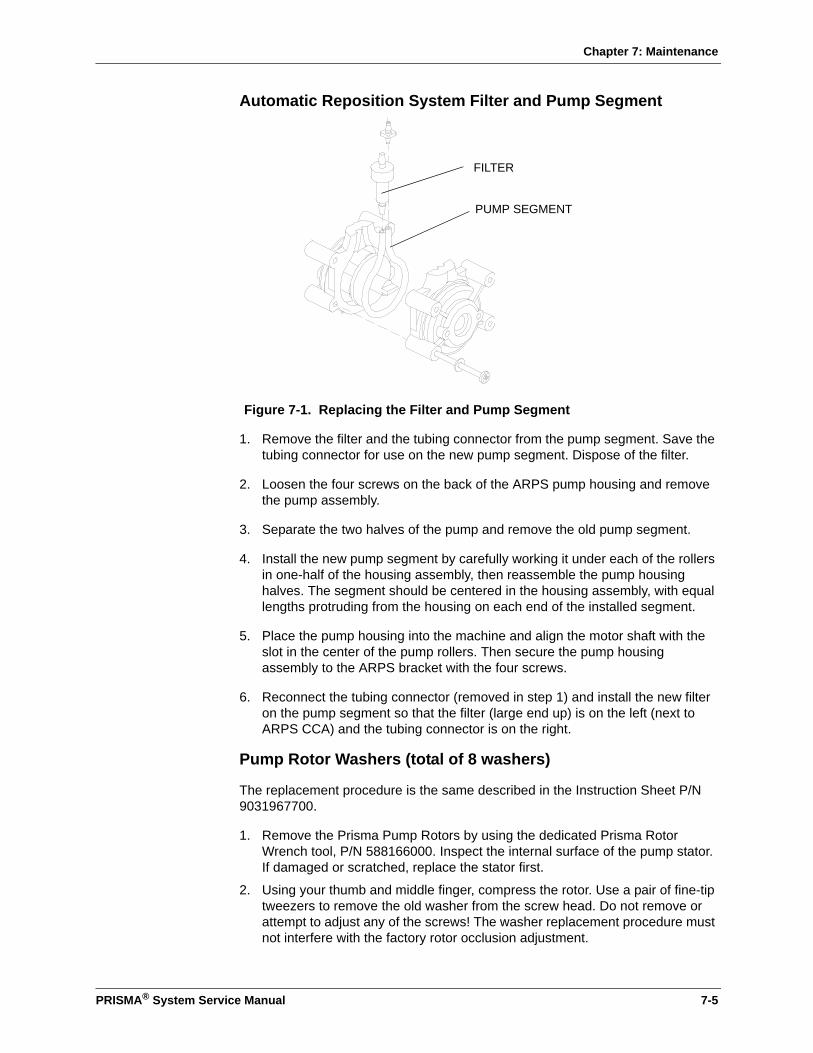
Chapter 7: Maintenance
Automatic Reposition System Filter and Pump Segment
Figure 7-1. Replacing the Filter and Pump Segment
1. Remove the filter and the tubing connector from the pump segment. Save the tubing connector for use on the new pump segment. Dispose of the filter.
2. Loosen the four screws on the back of the ARPS pump housing and remove the pump assembly.
3. Separate the two halves of the pump and remove the old pump segment.
4. Install the new pump segment by carefully working it under each of the rollers in one-half of the housing assembly, then reassemble the pump housing halves. The segment should be centered in the housing assembly, with equal lengths protruding from the housing on each end of the installed segment.
5. Place the pump housing into the machine and align the motor shaft with the slot in the center of the pump rollers. Then secure the pump housing assembly to the ARPS bracket with the four screws.
6. Reconnect the tubing connector (removed in step 1) and install the new filter on the pump segment so that the filter (large end up) is on the left (next to ARPS CCA) and the tubing connector is on the right.
Pump Rotor Washers (total of 8 washers)
The replacement procedure is the same described in the Instruction Sheet P/N 9031967700.
1. Remove the Prisma Pump Rotors by using the dedicated Prisma Rotor Wrench tool, P/N 588166000. Inspect the internal surface of the pump stator. If damaged or scratched, replace the stator first.
2. Using your thumb and middle finger, compress the rotor. Use a pair of fine-tip tweezers to remove the old washer from the screw head. Do not remove or attempt to adjust any of the screws! The washer replacement procedure must not interfere with the factory rotor occlusion adjustment.
FILTER
PUMP SEGMENT
PRISMA® System Service Manual 7-5
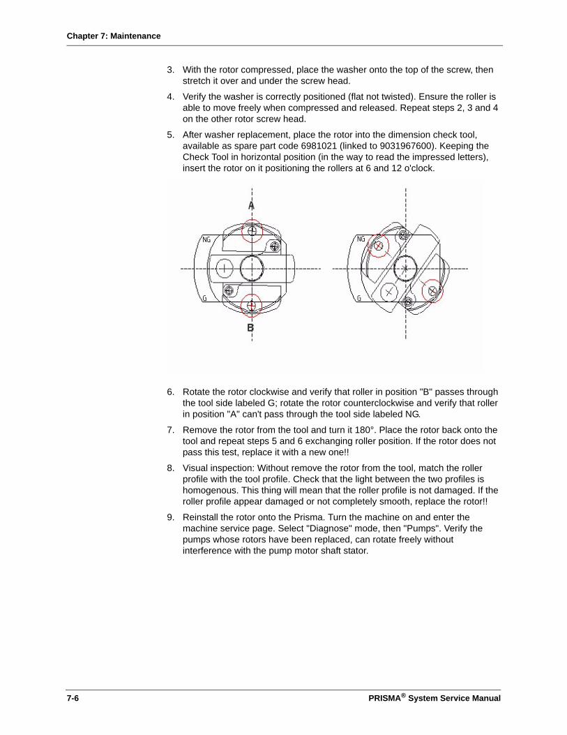
Chapter 7: Maintenance
3. With the rotor compressed, place the washer onto the top of the screw, then stretch it over and under the screw head.
4. Verify the washer is correctly positioned (flat not twisted). Ensure the roller is able to move freely when compressed and released. Repeat steps 2, 3 and 4 on the other rotor screw head.
5. After washer replacement, place the rotor into the dimension check tool, available as spare part code 6981021 (linked to 9031967600). Keeping the Check Tool in horizontal position (in the way to read the impressed letters), insert the rotor on it positioning the rollers at 6 and 12 o'clock.
6. Rotate the rotor clockwise and verify that roller in position "B" passes through the tool side labeled G; rotate the rotor counterclockwise and verify that roller in position "A" can't pass through the tool side labeled NG.
7. Remove the rotor from the tool and turn it 180°. Place the rotor back onto the tool and repeat steps 5 and 6 exchanging roller position. If the rotor does not pass this test, replace it with a new one!!
8. Visual inspection: Without remove the rotor from the tool, match the roller profile with the tool profile. Check that the light between the two profiles is homogenous. This thing will mean that the roller profile is not damaged. If the roller profile appear damaged or not completely smooth, replace the rotor!!
9. Reinstall the rotor onto the Prisma. Turn the machine on and enter the machine service page. Select "Diagnose" mode, then "Pumps". Verify the pumps whose rotors have been replaced, can rotate freely without interference with the pump motor shaft stator.
7-6 PRISMA® System Service Manual

Chapter 7: Maintenance
3. Power Supply Check on Power Supply Interface CCA
Connect the machine's power cord to the electrical outlet and turn on the power switch. Allow the machine to warm up for about 5 minutes
• + 12 V +11.52 to +12.48 TP1 to TP4(gnd)
• + 24 V +23.04 to +24.96 TP2 to TP4(gnd)
Note: Check 24V with return clamp open
• + 5 V +5.00 to +5.30 T P3 to TP4(gnd)
• - 5 V -4.80 to -5.20 TP5 to TP4(gnd)
4. Service Mode Checkout
Note: Some service references to the effluent pump are listed as waste pump.
Enter Service-Diagnose mode. Follow the instructions on the following pages to verify the proper operation and/or calibration of the components listed below.
• Pumps
• Scales
• Pressure
• Reposition Pressure
• Lights and alarm tones
• Air detector
• Syringe pump
• Return clamp
• Blood Leak detector
• Load/unload
• Internal System
• Pod reposition
If any items are out of calibration, replace and/or calibrate as needed to correct the problem.
To enter the Service-Diagnose mode, you must enter the Service Mode and press the Diagnose softkey that appears on the left side of the screen.
Note: The Exit softkey appears on every Service-Diagnose screen. Any time the Exit key is pressed, the PRISMA returns to the Service-Diagnose screen.
PRISMA® System Service Manual 7-7

Chapter 7: Maintenance
7-8 PRISMA® System Service Manual
Service-Pumps Diagnose Screen
1. From the Service-Diagnose screen, press the Pumps softkey.
Note: Two or more motors can be tested simultaneously. You should test each of the pump motors as follows:
2. Select the pump to be tested by pressing one of the pump softkeys (Replace, Effluent, Dialysate or Blood).
3. When you select a pump, the up and down arrow softkeys appear on the right side of the display. Pressing the up arrow softkey increases the pump motor speed and pressing the down arrow softkey decreases the motor speed. (The pump motor speed is indicated in rpms).
4. Press the up arrow softkey and release it when the pump speed, shown below, is displayed under the Set column on the screen. The motor will start as soon as you release the arrow softkey. Verify that the TACH speed is the same as the Set speed with the shown tolerance.
Note: The Blood Pump will ramp up to the desired speed.
• Replacement: 6 rpm ±1
• Effluent: 17 rpm ±2
• Dialysate: 8 rpm ±1
• Blood: 44 rpm ±4
5. Once the motor is running, press the up arrow softkey to increase the Set motor speed the higher speed shown below. Again, verify that the TACH speed is the same as the Set speed with the shown tolerance.
• Replacement: 30 rpm ±3
• Effluent: 83 rpm ±8
• Dialysate: 38 rpm ±4
• Blood: 222 rpm ±22
6. Press the 24 VOLTS ON Softkey. This softkey displays the status of the +24 Vdc (on or off). Turning off the 24 Vdc MUST stop the pumps.
7. Press the 24 VOLTS OFF softkey to enable the +24 Vdc.
8. Change the direction of each motor by pressing the Direction softkey. The motor will start running in the opposite direction. Note that the motors always start up in the clockwise (CW) direction. The actual direction of rotation (CW or CCW) must be indicated in the column labeled Direction for both directions.
9. Again, verify that the TACH speed is the same as the set speed with the shown tolerance.
• Replacement: 30 rpm ±3
• Effluent: 83 rpm ±8
• Dialysate: 38 rpm ±4
• Blood: 222 rpm ±22

Chapter 7: Maintenance
10. Press the 24 Volts On Softkey. This softkey displays the status of the +24 Vdc (on or off). Turning off the 24 Vdc MUST stop the pumps.
11. Press the Exit softkey to exit the Service Pumps screen and enter the Service-Scales screen.
Service-Scales Diagnose Screen
The Service-Scales diagnose screen displays the averaged scale readings for the control and monitor Weight Transducer's, and the associated A/D values. The weight and A/D values at each Weight Transducer is continuously displayed in the row next to the scale name.
1. With no weight on any of the scales, the A/D Monitor and Control values should both be -3000 ±500. The Averaged- grams readings for Monitor and Control should both be 0 ±7 grams.
2. Place one of the 2600 gram weights on each scale and monitor the values. Both the Monitor and Control readings should be 2600 ±7 grams.
3. Place both of the 2600 gram weights on each scale and monitor the values. Both the Monitor and Control readings should be 5200 ±7 grams.
4. Press the Next Diagnostic softkey to exit the Service Scales screen and enter the Service-Pressure screen.
Service Pressure Diagnose Screen
The Service-Pressure diagnose screen displays instantaneous and 5-second averaged values for each of the pressure monitoring systems. The pressure at each pressure monitor is continuously displayed in the row next to the monitor name.
When applying pressure to the pressure test pods, attach an external pressure meter to the pressure test pod to verify accuracy.
1. With the pressure monitors open to the ambient atmospheric pressure, the pressure must read 0, ±3 mmHg and A/D will read 500, ±50 cnt.
2. Place a pressure test pod on each of the pressure ports.
3. Attach a syringe to the pressure test pod on the Return pressure port and apply a pressure of +300 mmHg to the transducer. The A/D values will increase and the Averaged mmHg value must indicate +300, ±10 mmHg.
4. Attach a syringe to the pressure test pod on the Filter pressure port and apply a pressure of +400 mmHg to the transducer. The A/D values will increase and the Averaged mmHg value must indicate +400, ±10 mmHg.
5. Attach a syringe to the pressure test pod on the Effluent pressure port and apply a pressure of -300 mmHg to the transducer. The A/D values will decrease and the Averaged mmHg value must indicate -300, ±10 mmHg.
6. Attach a syringe to the pressure test pod on the Access pressure port and apply a pressure of -200 mmHg to the transducer. The A/D values will decrease and the Averaged mmHg value must indicate -200, ±10 mmHg.
PRISMA® System Service Manual 7-9

Chapter 7: Maintenance
Reposition Transducer
1. Press the Enable Reposition Transducer softkey to open the access reposition valve and allow the pressure applied at the access pressure pod to register on both the reposition and access transducers. The reposition transducer A/D value will read approximately 128.
2. Use a syringe attached to the pressure test pod on the Access pressure port to apply a pressure of -200 mmHg to the transducer. The A/D values for the Reposition transducer will increase and the Averaged mmHg value must indicate -200 ±10 mmHg.
3. Use a syringe attached to the pressure test pod on the Access pressure port to apply a pressure of +200 mmHg to the transducer. The A/D values for the Reposition transducer will decrease and the Averaged mmHg value must indicate +200 ±10 mmHg.
4. Press the Next Diagnostic softkey to exit the Service Pressure screen and enter the Service-Lights and Tones screen.
Service-Lights and Tones Diagnose Screen
1. Press the Warning Tone softkey. A continuous stream of beeps should be heard.
2. Press the Malfunction Tone softkey. A continuous stream of beeps should be heard.
3. Press the Caution Tone softkey. An intermittent double-beep should be heard.
4. Press the Advisory Tone softkey. One beep every 10 seconds should be heard.
5. Press the Red Light softkey. This will silence the tone and cause the red lamp to illuminate continuously.
6. Press the Yellow Light softkey. The Yellow lamp will illuminate continuously.
7. Press the Green Light softkey. The Green lamp will illuminate continuously.
8. Press the Next Diagnostic softkey to exit the Service-Light and Tones screen and enter the Service-Air Detector screen.
Service-Air Detector Screen
1. Install a fluid-filled tube in the air bubble detector housing.
2. Press the Macro Test softkey to simulate a macro-size air bubble. The Controller and Monitor Macro Bubble should display a Yes, indicating that the system has detected a macro-size bubble.
3. When the Macro Test softkey is released to end the test, the Troub: indicator should briefly flash "Yes".
4. Press the Micro Test softkey to simulate micro-size air bubbles. The Micro Count display should begin increasing, indicating that the system has detected micro-size bubbles.
5. Press the Next Diagnostic softkey so the machine will leave the Service-Air Detector screen and enter the Service-Syringe Pump screen.
7-10 PRISMA® System Service Manual

Chapter 7: Maintenance
Service-Syringe Pump Diagnose Screen
Note: You will need a stopwatch for the following procedure.
1. Install a 20 cc syringe into the Heparin Pump and adjust the plunger to 15 ml mark.
2. Press the Bolus softkey. The syringe pump should deliver a 5 ±0.5 ml bolus.
3. Press the Adjust Rate softkey. An up arrow and a down arrow appear on the right side of the screen. Set the delivery rate for the syringe pump to 20 ml/hr.
4. Press the Continuous softkey and start the stopwatch. Verify that the syringe pump delivers 4 ± 0.5 ml in 12 minutes, then stop the stopwatch. When the syringe pump is operating, the Monitor rate display value should be changing, indicating that the monitor microprocessor is receiving the stepper motor signal increments.
5. When the delivery rate accuracy is verified, press the Stop softkey.
6. The syringe pump must stop when in the Continuous mode only. This softkey does not affect heparin delivery in the Bolus mode.
7. Remove the syringe from the syringe clamp. Press the Bolus softkey and press down on the syringe clamp to keep it from moving. Start the stopwatch. Within 30 seconds the Bolus should stop and "End of Travel" should indicate "Yes".
8. Press the Next Diagnostic softkey to exit the Service-Syringe Pump screen and enter the Service-Clamp screen.
Service-Clamp Diagnose Screen
1. Press the Clamp Command softkey to open or close the line clamp. The command status of the clamp is displayed immediately above this softkey. The monitored status is in the "Clamp status:" display. The display above the Clamp Command softkey and the "Clamp status:" display must agree.
2. Make sure the clamp is open. Press the Monitor Power softkey. The clamp should close and the "clamp status" display should also indicate a closed reading. The display above the Monitor Power softkey should indicate "Off".
3. To open the clamp, press the Monitor Power softkey until the display above the softkey reads "On". Press the Clamp Command softkey twice and the clamp will open.
4. Press the Control Power softkey. The clamp should close and the "clamp status" display should also indicate a closed reading. The display above the Control Power softkey should indicate "Off".
5. To open the clamp, press the Control Power softkey until the display above the softkey reads "On". Press the Clamp Command softkey twice and the clamp will open.
6. Press the Next Diagnostic softkey so the machine will leave the Service-Clamp screen and enter the Service-Blood Leak Detector screen.
PRISMA® System Service Manual 7-11
Chapter 7: Maintenance
Service-Blood Leak Detector Diagnose Screen
1. Fill the effluent tubing segment with water and install the tubing in the blood leak detector housing. NOTE: The tubing must be from a Prisma blood set.
2. Press and release the Normalize softkey. Use the arrow keys to raise or lower the DAC value until it equals the Normalize value.
Note: The Normalize value that appears after the Normalize softkey is pressed is stored only for use during the current Service mode. The blood leak detector Normalize value is re-calibrated and stored during the Prime Self-Test.
3. Verify that the Difference value is between 167 and 184 and the DAC value is greater than 30.
4. Press and hold the Test softkey. The Signal 2 value will decrease to a minimal value which must cause the Difference and Average values to drop below 81.
5. Adjust the DAC value to 35. The Difference should read a value lower than 229.
6. Remove the tubing from the blood leak detector.
The Difference should be higher than 229.
7. Press the Exit softkey to exit the Service-Blood Leak Detector screen and enter the Service-Diagnose screen.
Load/Unload Functions
• When the Load softkey is illuminated, all the pumps run counterclockwise (CCW)
• When the Unload softkey is illuminated, all the pumps run clockwise (CW)
1. Press the Load/Unload softkey which is located just above the Exit softkey. If the softkey currently shows Load, the cartridge holder clamp should be in the 'out' position. Pressing the softkey should cause the cartridge holder to retract, and the pumps should turn in the proper direction.
2. The softkey should now display the second option. Press the softkey and verify that the pumps turn in the proper direction and the cartridge clamp holder moves in the appropriate direction.
3. Press the REPO softkey to enter the Service-Pod Reposition Screen.
Service-Pod Reposition Diagnose Screen
Effluent Valve1. Install a test pressure pod on each of the pressure pod housings. Close all
tubing clamps.
2. Press the Effluent Valve softkey. The softkey will illuminate and the Effluent valve for the repositioning system will open.
3. Press the Direction softkey until the "Motor Direction" display indicates Decrease, then press the Motor softkey to begin changing the pressure.
4. When the Effluent Valve Pressure display reaches approximately -200 mmHg, press the Motor softkey again to stop the pump.
The "Reposition Press." display should decrease at the same rate as the valve pressure display, and should be approximately the same value.
7-12 PRISMA® System Service Manual

Chapter 7: Maintenance
5. Press the Effluent valve softkey again. The softkey illumination should turn off and that valve for the repositioning system should close.
Access Valve1. Press the Access Valve softkey. The softkey will illuminate and the Access
valve for the repositioning system will open.
2. Press the Direction softkey until the "Motor Direction" display indicates Decrease, then press the Motor softkey to begin changing the pressure.
3. When the Access Valve Pressure display reaches approximately -150 mmHg, press the Motor softkey again to stop the pump. The "Reposition Press." display should decrease at the same rate as the valve pressure display, and should be approximately the same value.
4. Press the Access valve softkey again. The softkey illumination should turn off, and that valve for the repositioning system should close.
Filter Valve1. Press the Filter Valve softkey. The softkey will illuminate and the Filter valve
for the repositioning system will open.
2. Press the Direction softkey until the "Motor Direction" display indicates Increase, then press the Motor softkey to begin changing the pressure.
3. When the Filter Valve Pressure display reaches approximately +200 mmHg, press the Motor softkey again to stop the pump. The "Reposition Press." display should increase at the same rate as the valve pressure display, and should be approximately the same value.
4. Press the Filter valve softkey again. The softkey illumination should turn off, and that valve for the repositioning system should close.
Return Valve1. Press the Return Valve softkey. The softkey will illuminate and the Return
valve for the repositioning system will open.
2. Press the Direction softkey until the "Motor Direction" display indicates Increase, then press the Motor softkey to begin changing the pressure.
3. When the Return Valve Pressure display reaches approximately +200 mmHg, press the Motor softkey again to stop the pump. The "Reposition Press." display should increase at the same rate as the valve pressure display, and should be approximately the same value.
4. Press the Return valve softkey again. The softkey illumination should turn off, and that valve for the repositioning system should close.
5. Remove the test pressure pods from all of the pressure pod housings.
6. Press the Next Diagnostic softkey to exit the Service-Pod Reposition screen and enter the Service-Internal screen.
PRISMA® System Service Manual 7-13

Chapter 7: Maintenance
Service-Internal Screen
Note: You will need a stopwatch for the following procedure.
1. Press the Test Monitor Watchdog softkey and start the stopwatch. Within 1.5 seconds a system reset should be generated, causing the PRISMA to restart.
2. Turn off the machine. Re-enter the Service Mode and return to the Service-Internal screen.
3. Press the Test Control Watchdog softkey and start the stopwatch. Within 1.5 seconds a system reset should be generated, causing the PRISMA to restart. NOTE: Checksum Interrupted Alarm may occur and will need to be cleared from the main service screen.
4. Turn off the machine. Reenter the Service Mode and return to the Service-Internal screen.
5. Press the Test Video softkey. The display turns all the pixels on for a few seconds, then off. Verify that all pixels are lighted when the display is on, and that none are lighted when the display is off.
6. Press the Test Softkey softkey. Each softkey location is shown. Press each one of the softkey locations and verify the softkey illuminates until another softkey is pressed or when the Exit softkey is pressed.
This indicates that the softkey is functioning properly.
7. Press the Exit softkey Twice to exit the Service-Diagnose screen.
5. Functional Checkout
Before releasing the PRISMA Control Unit System for use, perform the functional checkout with a PRISMA Set in place on the control unit.
The test is performed using saline solution as a substitute for priming, replacement and dialysate solutions, and a container of water as a substitute for the patient. Successful completion of the functional checkout indicates that the PRISMA Control Unit is operating properly.
• A patient must not be connected to the PRISMA System during the functional checkout. Be sure that the checkout is conducted using a container of water to substitute for the patient.
• If a Malfunction alarm occurs during the functional checkout, the PRISMA Control Unit has failed the checkout. Do not use the control unit until the problem has been corrected and the control unit has passed the checkout. If you need additional information to perform certain functions, see Chapter 2: Operation.
WARNING
!
7-14 PRISMA® System Service Manual

Chapter 7: Maintenance
Setup and Prime
1. Turn on the PRISMA as described under Startup in the Operation chapter. The PRISMA performs an initialization test during the Startup procedure. Verify that the red, yellow, and green lights are illuminated during the initialization test.
2. Enter Test Mode when the Choose Patient screen appears. Refer to Chapter 5 of this Manual for additional information on Test Mode.
3. Select New Patient and confirm New Patient choice by pressing Continue on the Confirm Patient screen.
4. Set the Excess Pt. Fluid Loss or Gain Limit to 140 ml/3h and press Confirm to accept the limit. Select the CVVHDF therapy when the Choose Therapy screen appears.
5. Follow the instructions on the display to load the set. During loading of the set, ensure that each pump segments load into the pump properly. Verify that the carriage plate positions flat on the front panel of the machine.
6. Follow instructions on the display to Prime the set. Use saline solution in place of replacement and dialysate solutions. The PRISMA performs multiple self-tests during the priming cycle.
Fluid Accuracy
1. When priming is complete, press Continue, and the Set- Flow Rates screen appears. Set the following flow rates:
Blood: 100 ml/minDialysate: 1000 ml/hrReplacement: 1000 ml/hrInitial Pt. Fluid Removal Rate: 0 ml/hrAnticoagulant: Continuous Delivery at 0 ml/hr
2. Place the access and return lines into the fluid filled graduated cylinder; press the Continue softkey, followed by the Start softkey, to enter Run mode.
3. Adjust the slide clamps on the Access and Return lines to display pressures of -30mmHg to -60mmHg for Access and +30mmHg to +60mHg for Return in the Status Screen.
4. Ensure that water level in the graduated cylinder is at 1000ml to reduce the initial error. The Display and Actual Fluid Removed should be within the following specifications.
Actual Fluid Removed (graduated cylinder) = 0 ±5mlDisplayed Fluid Removed (screen) = Actual Fluid Removed (graduated cylinder) ±5ml.
1. Note the time as indicated by the Prisma real-time clock and set the Fluid Removal Rate to 800ml/hr. The noted time will be the Fluid Removal Start Time and can also be seen in the Events Screen.
PRISMA® System Service Manual 7-15
Chapter 7: Maintenance
Note: Alarms will affect the outcome of the functional checkout. If an alarm has occurred that stopped a peristaltic pump, the Actual Fluid Removed will not be accurate. Remedy the problem that caused the alarm and perform the functional checkout again.
2. Let the PRISMA run for 15 minutes. Note that the fluid totals in the I/O Data Box (center of Status screen) are updated as operation proceeds.
3. Set the History Start Time to the Fluid Removal Start Time. Set the History End Time to 15 minutes after the History Start Time. Ensure that the Displayed and Actual Fluid Removed are within the specification.
Actual Fluid Removed (graduated cylinder) = 200 ±10mlDisplayed Fluid Removed (screen) = Actual Fluid Removed (graduated cylinder) ±10ml.
4. Let the PRISMA run for another 15 minutes. Note that the fluid totals in the I/O Data Box (center of Status screen) are updated as operation proceeds.
5. Set the History Start Time to the Fluid Removal Start Time. Set the History End Time to 30 minutes after the History Start Time. Ensure that the Displayed and Actual Fluid Removed are within the specification.
Actual Fluid Removed (graduated cylinder) = 400 ±15mlDisplayed Fluid Removed (screen) = Actual Fluid Removed (graduated cylinder ±15ml.
Access Pressure Alarm Verification
1. Place a clamp on the Access line (red stripe) below the cartridge. The Warning: Access Pressure Extremely Negative alarm should occur. Verify that the red light illuminates continuously and the audible alarm sounds at a fast beep.
2. Unclamp the access line and press the CONTINUE softkey on the Warning screen. Verify that the alarm is cleared (Warning screen leaves display, green light illuminates).
Incorrect Weight Change Alarms
Note: A verification of fluid accuracy will be performed during this checkout procedure.
1. Press the Stop softkey. Then clamp the Replacement line with the slide clamp.
Note: DON'T use external clamps or add weight to the bags during the following tests.
2. Note the fluid level of the graduated cylinder. Press the Start softkey to continue with the treatment and also note the time as indicated by the Prisma real-time clock. This will be the Alarm Procedure Start Time
3. The PRISMA should alarm an Incorrect Weight Change Detected - Replacement.
7-16 PRISMA® System Service Manual
Chapter 7: Maintenance
4. The Alarm Screen shall display " Excess Pt. Fluid Loss: 21 ml " (±5ml) and " Treatment stops if Pt. Fluid Loss exceeds: 140 ml ".
5. Unclamp the Replacement line and clamp the Dialysate line. Press the Continue softkey to generate an Incorrect Weight Change Detected - Dialysate alarm.
6. The Alarm Screen shall display " Excess Pt. Fluid Loss: 42 ml " (±10ml) and " Treatment stops if Pt. Fluid Loss exceeds: 140 ml ".
7. Unclamp the Dialysate line and clamp the Effluent line. Press the Continue softkey to generate an Incorrect Weight Change Detected - Effluent alarms.
8. The Alarm Screen shall display " Excess Pt. Fluid Loss: 19 ml " (±5ml) and " Treatment stops if Pt. Fluid Loss exceeds: 140 ml ".
Excess Pt. Fluid Loss or Gain Alarm
1. Press the Continue softkey over and over to generate following Caution: Incorrect Weight Change Detected - Effluent alarms . Each Alarm Screen shall display a 24ml variation of the Excess Pt. Fluid value (±5ml).
2. The Excess Pt. Fluid value displayed on the Caution: Incorrect Weight Change Detected - Effluent alarms shall be always lower than the threshold accepted in Setup, equal to 140 ml/ 3h .
3. A " Caution: Excess Pt. Fluid Loss or Gain " alarm shall be generated when the threshold is reached. This Alarm Screen shall display:
• Excess Pt. Fluid Gain: xxxx ml (xxxx shall be higher or equal than 140 ml)
• Excess Patient Fluid Loss or Gain Limit: 140 ml
4. Note the Actual Fluid Removed from the graduated cylinder; wait al least 1 minute, press the " End Treatment " button and reach the " Treatment Complete " Screen to access the Treatment History.
Fluid Accuracy During Alarm
1. The Actual Fluid Removed shall be -50 ml ±10ml (the patient has gained weight).
Note: The Actual Fluid Removed noted previously is a result from the therapy time elapsed and from the number of errors.
2. Press the Events button to access Events and note the Time when the End Treatment button has been pressed.
3. Press the " Treatment History " button and set the History Start Time to the Alarm Procedure Start Time. Set the History End Time to the End treatment time noted previously. Displayed Fluid Removed should be the same as the Actual Fluid Removed from the graduated cylinder ±10ml.
Note: This error is a result from the therapy time elapsed to generate the alarm.
PRISMA® System Service Manual 7-17

Chapter 7: Maintenance
6. Electrical Safety Inspection
Electrical Safety Inspection Tests
Note: Before performing the remaining tests, turn off the power switch and disconnect the mains plug from the electrical outlet.
Primary Fusing
Examine the fuses to verify that they are of the appropriate value:
Parameter Performance Conditions
Earth Leakage Current Test Per IEC 601.1, para. 19.4
50 µA maximum Protective ground intact.
110 Vac, 50/60 Hz 300 µA maximum
Protective ground open.
200 Vac, 50/60 Hz 500 µA maximum
Protective ground open.
Parameter Performance Conditions
Ground Integrity Test per IEC 601.1, para. 18. f
0.1 ohm maximum Between protective conductor in appliance inlet and any accessible conductive part of the machine.
0.2 ohm maximum Between earth ground in mains plug and any accessible conductive part of the machine.
Parameter Performance Conditions
Power Supply Inlet (2 fuses)
Type: Fast-blow Rating: 250 Vac, 6.3 A
Mains Power Inlet (2 fuses)
Type: Fast-blow Rating: 250 Vac, 5 A
7-18 PRISMA® System Service Manual

Chapter 7: Maintenance
7. Warning Label
Verify that the WARNING LABEL code 90314153xx Revision B or upper is applied on the effluent scale.
Verify that the WARNING LABEL code 90321070xx Revision / or above is applied near the touch screen, right or left side.
8. PM Sticker
Fill in the PM sticker and apply to the machine.
9. Preventive Maintenance Timer Status
a. Connect the mains plug to the electrical outlet and turn the machine on.
b. Enter Service-Diagnose mode
c. Press the Internal softkey
d. Select Set PM Timer Status from the Service-internal screen
e. Set the preventive maintenance timer to “0 hours since last PM”
Preventive Maintenance Checklist
Fill out the Preventive Maintenance checklist. File a copy of the checklist with the appropriate hospital and manufacturer/distributor personnel.
PRISMA® System Service Manual 7-19
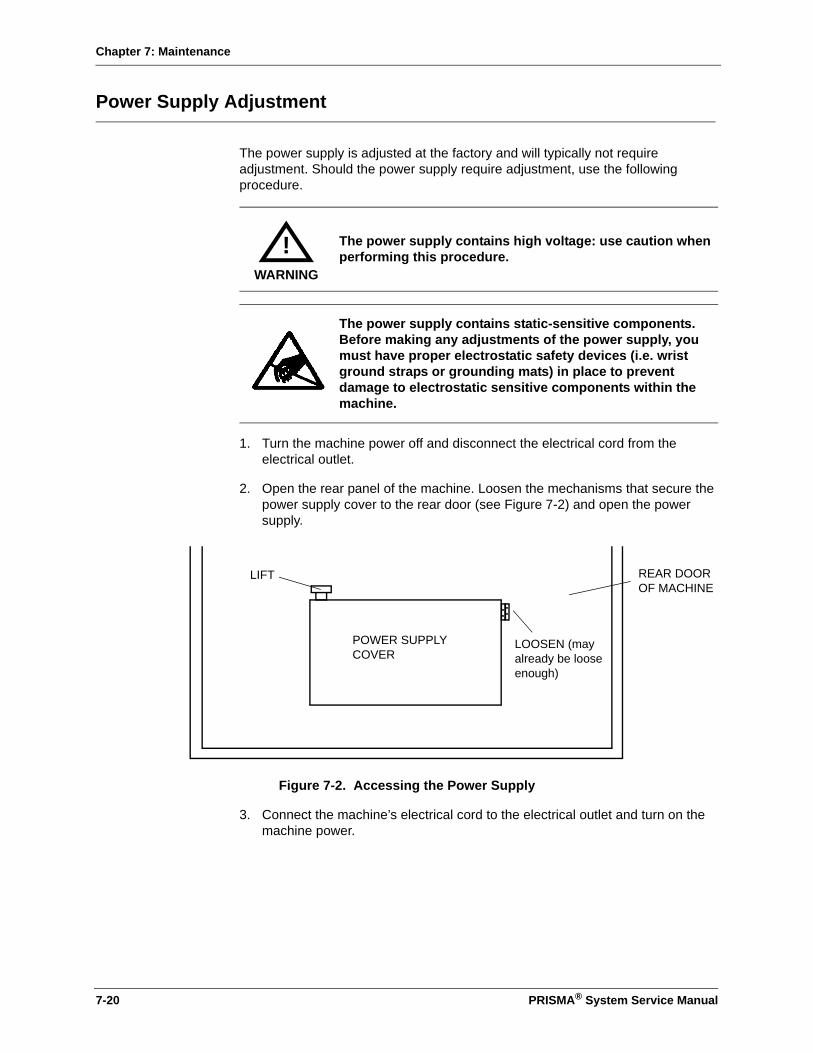
Chapter 7: Maintenance
Power Supply Adjustment
The power supply is adjusted at the factory and will typically not require adjustment. Should the power supply require adjustment, use the following procedure.
1. Turn the machine power off and disconnect the electrical cord from the electrical outlet.
2. Open the rear panel of the machine. Loosen the mechanisms that secure the power supply cover to the rear door (see Figure 7-2) and open the power supply.
Figure 7-2. Accessing the Power Supply
3. Connect the machine’s electrical cord to the electrical outlet and turn on the machine power.
The power supply contains high voltage: use caution when performing this procedure.
The power supply contains static-sensitive components. Before making any adjustments of the power supply, you must have proper electrostatic safety devices (i.e. wrist ground straps or grounding mats) in place to prevent damage to electrostatic sensitive components within the machine.
WARNING
!
REAR DOOR OF MACHINE
LIFT
LOOSEN (may already be loose enough)
POWER SUPPLY COVER
7-20 PRISMA® System Service Manual

Chapter 7: Maintenance
4. The adjusting potentiometer locations are shown in Figure 7-3. The voltage ranges for the power supplies are shown in the table below.
Figure 7-3. Power Supply Adjusting Potentiometer Location
Note: If you adjust the +24 supply, you must re-check all other voltages and verify that they are within tolerance. If they are not within tolerance, adjust each supply as necessary.
5. Using a calibrated voltmeter and potentiometer adjusting tool, adjust the potentiometers as necessary.
6. Turn the machine off and secure the power supply to the rear panel.
7. Turn the machine on and calibrate the scales (see “Service-Scales Calibrate Screen” on page 5-5) and pressures (see “Service-Pressure Calibrate Screen” on page 5-6).
Restoring Monitor CCA BBRAMs
Whenever the Monitor CCA is replaced, the software version is changed or recovering the machine from certain alarms, the BBRAM in the control unit must be restored.
Voltage Range Measure between ground and:
+5.15 +5.0 to +5.3 TP3, Power Distribution CCA
+24 +23.04 to +24.96 TP2, Power Distribution CCA
–5 –4.8 to –5.2 TP5, Power Distribution CCA
+12 +11.52 to +12.48 TP1, Power Distribution CCA
This procedures erases all custom mode settings, treatment history, language, the PM timer status and all other control unit settings.
POWER SUPPLY CHASSIS
+5.15 Vdc POTENTIOMETER
+24 Vdc POTENTIOMETER
–5 Vdc POTENTIOMETER
+12 Vdc POTENTIOMETER
CAUTION
!
PRISMA® System Service Manual 7-21

Chapter 7: Maintenance
If possible, record all the custom settings, the PRISMA ID number, the PM TImer status, and the Filter Clotting Limit before changing the Monitor CCA or software. You can re-enter these values after the CCA or software change is complete.
1. Once you have installed the new CCA or software, put the machine in Service mode.
2. Clear any Malfunction: BB Memory or Malfunction: Checksum Interrupted alarm screens that may appear.
3. On the main Service screen, do the following if the Examine Alarms softkey appears:
a. Enter the Examine Alarms screen by pressing the Examine Alarms softkey.
b. Press the Clear Alarms softkey if present.
c. Return to the main Service screen by pressing the Exit softkey.
4. Once your are on the main Service screen, press Diagnose, then press the Internal softkey.
5. On the Service-Internal screen, press the Restore Defaults softkey twice - this erases all memory in the control unit.
6. On the Service-Internal screen press the Set PM TImer Status softkey and use the arrow softkeys to enter the correct PM time setting.
7. Exit the Service-Internal and the Service-Diagnose screens by pressing the Exit softkey.
8. Calibrate all the scales and pressure transducers.
9. Set the Filter Clotting Limits, clock, and PRISMA ID.
10. Press the Restart softkey to enter the Run mode.
11. On the Choose Patient screen, press the Custom Mode softkey and enter all of the appropriate alarm limits, flow rates, and settings for all therapies.
7-22 PRISMA® System Service Manual
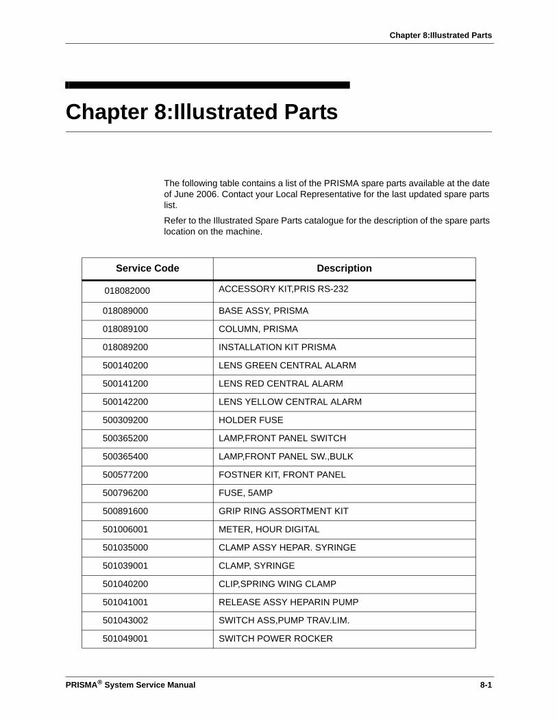
Chapter 8:Illustrated Parts
Chapter 8:Illustrated Parts
The following table contains a list of the PRISMA spare parts available at the date of June 2006. Contact your Local Representative for the last updated spare parts list.
Refer to the Illustrated Spare Parts catalogue for the description of the spare parts location on the machine.
Service Code Description
018082000 ACCESSORY KIT,PRIS RS-232
018089000 BASE ASSY, PRISMA
018089100 COLUMN, PRISMA
018089200 INSTALLATION KIT PRISMA
500140200 LENS GREEN CENTRAL ALARM
500141200 LENS RED CENTRAL ALARM
500142200 LENS YELLOW CENTRAL ALARM
500309200 HOLDER FUSE
500365200 LAMP,FRONT PANEL SWITCH
500365400 LAMP,FRONT PANEL SW.,BULK
500577200 FOSTNER KIT, FRONT PANEL
500796200 FUSE, 5AMP
500891600 GRIP RING ASSORTMENT KIT
501006001 METER, HOUR DIGITAL
501035000 CLAMP ASSY HEPAR. SYRINGE
501039001 CLAMP, SYRINGE
501040200 CLIP,SPRING WING CLAMP
501041001 RELEASE ASSY HEPARIN PUMP
501043002 SWITCH ASS,PUMP TRAV.LIM.
501049001 SWITCH POWER ROCKER
PRISMA® System Service Manual 8-1
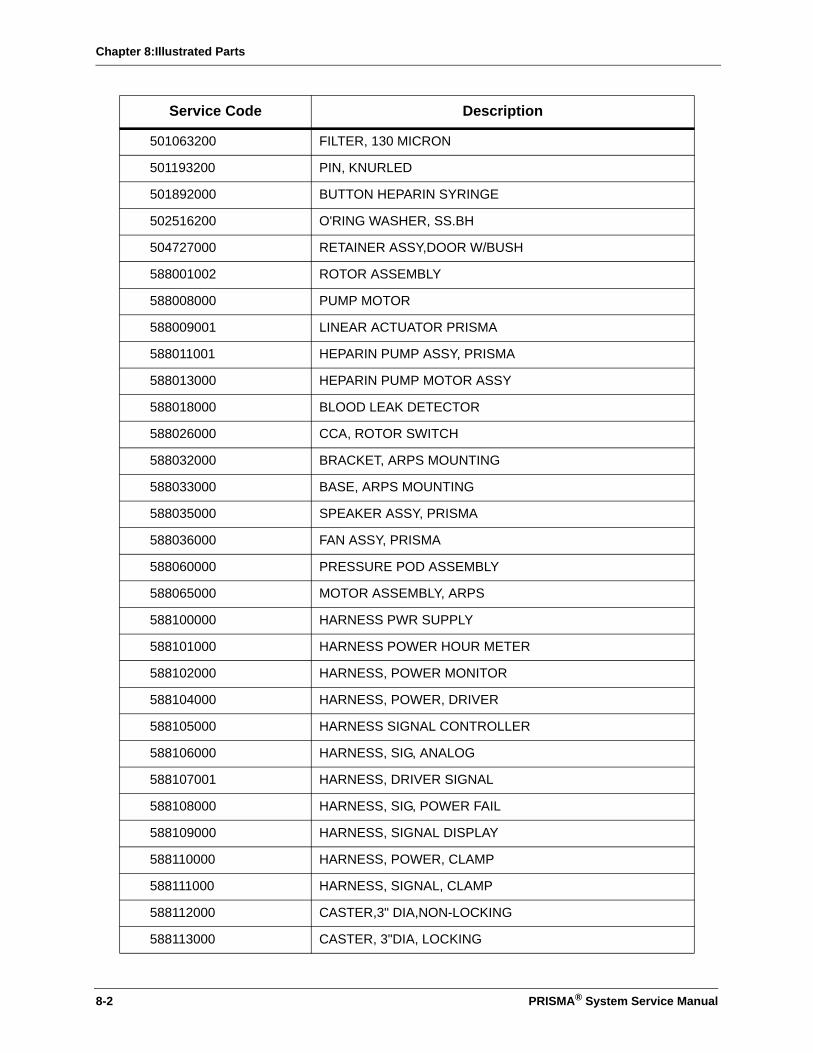
Chapter 8:Illustrated Parts
501063200 FILTER, 130 MICRON
501193200 PIN, KNURLED
501892000 BUTTON HEPARIN SYRINGE
502516200 O'RING WASHER, SS.BH
504727000 RETAINER ASSY,DOOR W/BUSH
588001002 ROTOR ASSEMBLY
588008000 PUMP MOTOR
588009001 LINEAR ACTUATOR PRISMA
588011001 HEPARIN PUMP ASSY, PRISMA
588013000 HEPARIN PUMP MOTOR ASSY
588018000 BLOOD LEAK DETECTOR
588026000 CCA, ROTOR SWITCH
588032000 BRACKET, ARPS MOUNTING
588033000 BASE, ARPS MOUNTING
588035000 SPEAKER ASSY, PRISMA
588036000 FAN ASSY, PRISMA
588060000 PRESSURE POD ASSEMBLY
588065000 MOTOR ASSEMBLY, ARPS
588100000 HARNESS PWR SUPPLY
588101000 HARNESS POWER HOUR METER
588102000 HARNESS, POWER MONITOR
588104000 HARNESS, POWER, DRIVER
588105000 HARNESS SIGNAL CONTROLLER
588106000 HARNESS, SIG, ANALOG
588107001 HARNESS, DRIVER SIGNAL
588108000 HARNESS, SIG, POWER FAIL
588109000 HARNESS, SIGNAL DISPLAY
588110000 HARNESS, POWER, CLAMP
588111000 HARNESS, SIGNAL, CLAMP
588112000 CASTER,3" DIA,NON-LOCKING
588113000 CASTER, 3"DIA, LOCKING
Service Code Description
8-2 PRISMA® System Service Manual

Chapter 8:Illustrated Parts
588114002 POWER SUPPLY ASSY PRISMA
588115000 DISPLAY, EL
588116000 SWITCH, TOUCHSCREEN
588117000 OVERLAY, TOUCHSCREEN
588118001 KIT SCALE CALIB. WEIGHT
588119000 SHELF, CALIBRATION WEIGHT
588120000 HOOK, SCALE
588121000 HARNESS, SIG, TOUCHSCREEN
588122200 THUMBSCREW, NYLON 6-32
588123600 LABEL, SCALE, SET
588124000 TOOL, CCA REMOVAL
588125000 TEST SET PRESS. POD ASSY
588126000 IC,XILINX,FPGA,XC303OPC84
588127100 IC, PROM, SERIAL CONF.
588130600 KIT CONNECTOR TUBING
588131000 IC,SER/PAR PORT 16C522
588133000 IC, PROM, MOTOR
588134000 IC MICROPROCESSOR 80C188
588135200 CLIP, TUBING, 3/16INCH
588136200 LABEL, MFG, PRISMA
588137000 CORD, POWER, EURO, 6A
588137100 POWER CORD, DOMESTIC PR.
588138000 HARNESS,DETECTOR,POWER
588139200 TUBING, ARPS PUMP HEADER
588142001 IC, 120NS1386RAM
588143000 SPARE,62256 SRAM 120NS
588144000 GROMMET, EDGE, PRISMA
588145200 TUBING,ARPS,0.31ID, 12"
588146000 RETURN PINCH VALVE ASSY
588147000 SWITCH SYRNGE PUMP EOT
588149000 LATCHING CARR. PLATE ASSY
Service Code Description
PRISMA® System Service Manual 8-3
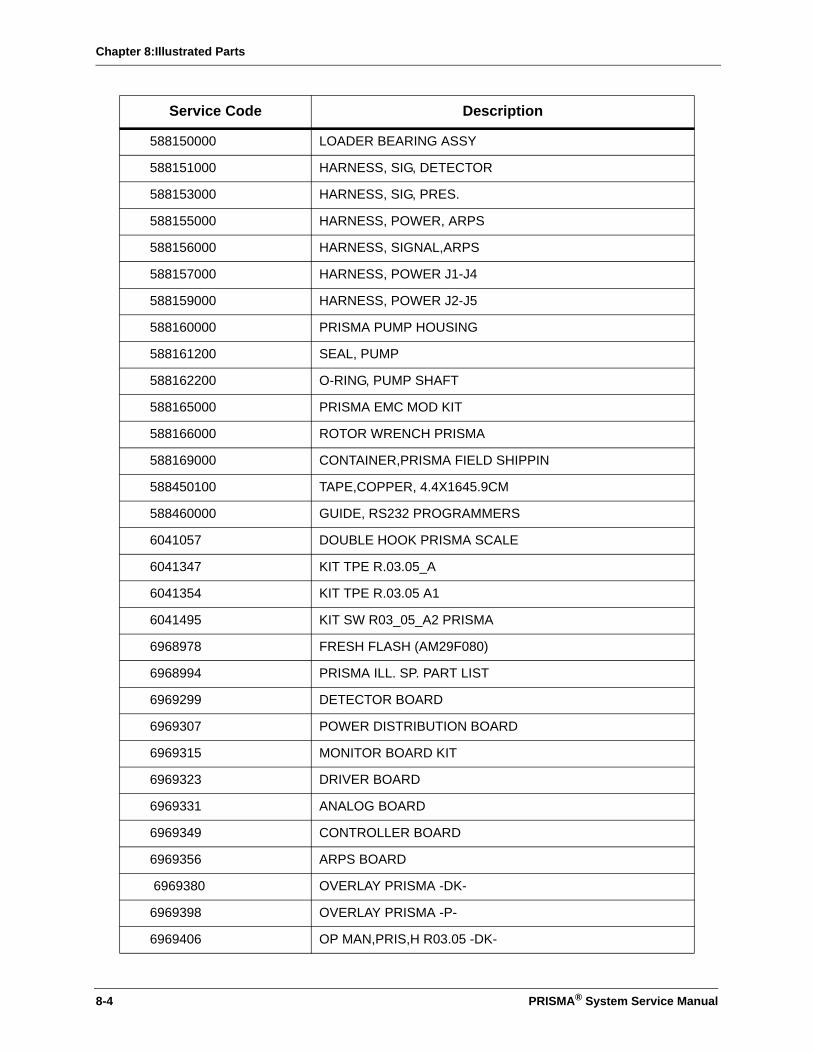
Chapter 8:Illustrated Parts
588150000 LOADER BEARING ASSY
588151000 HARNESS, SIG, DETECTOR
588153000 HARNESS, SIG, PRES.
588155000 HARNESS, POWER, ARPS
588156000 HARNESS, SIGNAL,ARPS
588157000 HARNESS, POWER J1-J4
588159000 HARNESS, POWER J2-J5
588160000 PRISMA PUMP HOUSING
588161200 SEAL, PUMP
588162200 O-RING, PUMP SHAFT
588165000 PRISMA EMC MOD KIT
588166000 ROTOR WRENCH PRISMA
588169000 CONTAINER,PRISMA FIELD SHIPPIN
588450100 TAPE,COPPER, 4.4X1645.9CM
588460000 GUIDE, RS232 PROGRAMMERS
6041057 DOUBLE HOOK PRISMA SCALE
6041347 KIT TPE R.03.05_A
6041354 KIT TPE R.03.05 A1
6041495 KIT SW R03_05_A2 PRISMA
6968978 FRESH FLASH (AM29F080)
6968994 PRISMA ILL. SP. PART LIST
6969299 DETECTOR BOARD
6969307 POWER DISTRIBUTION BOARD
6969315 MONITOR BOARD KIT
6969323 DRIVER BOARD
6969331 ANALOG BOARD
6969349 CONTROLLER BOARD
6969356 ARPS BOARD
6969380 OVERLAY PRISMA -DK-
6969398 OVERLAY PRISMA -P-
6969406 OP MAN,PRIS,H R03.05 -DK-
Service Code Description
8-4 PRISMA® System Service Manual
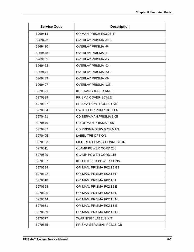
Chapter 8:Illustrated Parts
6969414 OP MAN,PRIS,H R03.05 -P-
6969422 OVERLAY PRISMA -GB-
6969430 OVERLAY PRISMA -F-
6969448 OVERLAY PRISMA -I-
6969455 OVERLAY PRISMA -E-
6969463 OVERLAY PRISMA -D-
6969471 OVERLAY PRISMA -NL-
6969489 OVERLAY PRISMA -S-
6969497 OVERLAY PRISMA -US-
6970321 KIT TRANSDUCER ARPS
6970339 PRISMA COVER SCALE
6970347 PRISMA PUMP ROLLER KIT
6970354 HW KIT FOR PUMP ROLLER
6970461 CD SERV.MAN.PRISMA 3.05
6970479 CD OP.MAN.PRISMA 3.05
6970487 CD PRISMA SERV.& OP.MAN.
6970495 LABEL TPE OPTION
6970503 FILTERED POWER CONNECTOR
6970511 CLAMP POWER CORD 230
6970529 CLAMP POWER CORD 115
6970537 KIT FILTERED POWER CONN.
6970594 OP. MAN. PRISMA R02.15 GB
6970602 OP. MAN. PRISMA R02.15 F
6970610 OP. MAN. PRISMA R02.15 I
6970628 OP. MAN. PRISMA R02.15 E
6970636 OP. MAN. PRISMA R02.15 D
6970644 OP. MAN. PRISMA R02.15 NL
6970651 OP. MAN. PRISMA R02.15 S
6970669 OP. MAN. PRISMA R02.15 US
6970677 "WARNING" LABELS KIT
6970875 PRISMA SERV.MAN.R02.15 GB
Service Code Description
PRISMA® System Service Manual 8-5

Chapter 8:Illustrated Parts
6970883 PRISMA SERV.MAN.R02.15 US
6970974 I.C. EPLD MONITOR DECODE
6970982 I.C. EPLD DRIVER
6970990 I.C. EPLD DETECTOR
6971063 UABD TRANSDUCER ASSY
6971410 KIT NEW PRISMA SCALE
6971428 HARNESS POWER AN.-SCALE
6971584 OP MAN,PRIS,H R03.05 -GB-
6971592 OP MAN,PRIS,H R03.05 -F-
6971600 OP MAN,PRIS,H R03.05 -I-
6971618 OP MAN,PRIS,H R03.05 -E-
6971626 OP MAN,PRIS,H R03.05 -D-
6971634 OP MAN,PRIS,H R03.05 -NL-
6971642 OP MAN,PRIS,H R03.05 -S-
6971691 FRESH EPROM (27256)
6971709 FRESH EPROM (27C020)
6971717 PRISMA SERV.MAN. R03.05
6972145 PRISMA SW R02_15_A
6972152 PRISMA SW R02_15_A1
6972160 PRISMA SW R02_15_A2
6972178 PRISMA SW R02_15_A3
6972186 KIT WARNING LABEL&MAN.ADD.
6972194 ADDENDUM OP. MAN. PRISMA
6972244 SW UP.R2_14_A TO R2_15_A
6973713 START UP KIT PRISMA NL
6973721 START UP KIT PRISMA E
6973739 START UP KIT PRISMA S
6973747 START UP KIT PRISMA I
6973754 START UP KIT PRISMA F
6973762 START UP KIT PRISMA US
6973770 START UP KIT PRISMA D
Service Code Description
8-6 PRISMA® System Service Manual
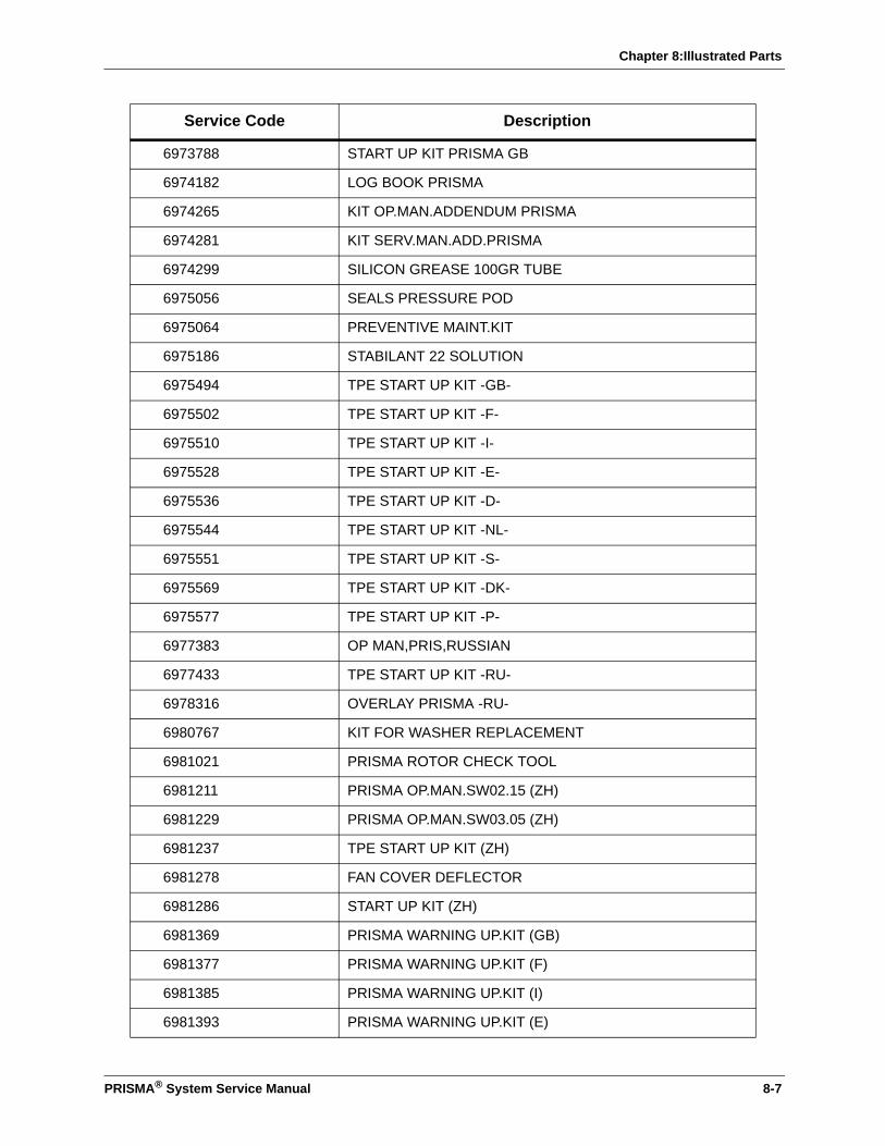
Chapter 8:Illustrated Parts
6973788 START UP KIT PRISMA GB
6974182 LOG BOOK PRISMA
6974265 KIT OP.MAN.ADDENDUM PRISMA
6974281 KIT SERV.MAN.ADD.PRISMA
6974299 SILICON GREASE 100GR TUBE
6975056 SEALS PRESSURE POD
6975064 PREVENTIVE MAINT.KIT
6975186 STABILANT 22 SOLUTION
6975494 TPE START UP KIT -GB-
6975502 TPE START UP KIT -F-
6975510 TPE START UP KIT -I-
6975528 TPE START UP KIT -E-
6975536 TPE START UP KIT -D-
6975544 TPE START UP KIT -NL-
6975551 TPE START UP KIT -S-
6975569 TPE START UP KIT -DK-
6975577 TPE START UP KIT -P-
6977383 OP MAN,PRIS,RUSSIAN
6977433 TPE START UP KIT -RU-
6978316 OVERLAY PRISMA -RU-
6980767 KIT FOR WASHER REPLACEMENT
6981021 PRISMA ROTOR CHECK TOOL
6981211 PRISMA OP.MAN.SW02.15 (ZH)
6981229 PRISMA OP.MAN.SW03.05 (ZH)
6981237 TPE START UP KIT (ZH)
6981278 FAN COVER DEFLECTOR
6981286 START UP KIT (ZH)
6981369 PRISMA WARNING UP.KIT (GB)
6981377 PRISMA WARNING UP.KIT (F)
6981385 PRISMA WARNING UP.KIT (I)
6981393 PRISMA WARNING UP.KIT (E)
Service Code Description
PRISMA® System Service Manual 8-7

Chapter 8:Illustrated Parts
6981401 PRISMA WARNING UP.KIT (D)
6981419 PRISMA WARNING UP.KIT (NL)
6981427 PRISMA WARNING UP.KIT (S)
6981435 PRISMA WARNING UP.KIT (DK)
6981443 PRISMA WARNING UP.KIT (P)
6981468 PRISMA WARNING UP.KIT (RU)
6981476 PRISMA WARNING UP.KIT (ZH)
6981484 PRISMA OP.MAN.UP.KIT (GB)
6981500 PRISMA OP.MAN.UP.KIT (F)
6981518 PRISMA OP.MAN.UP.KIT (I)
6981526 PRISMA OP.MAN.UP.KIT (E)
6981534 PRISMA OP.MAN.UP.KIT (D)
6981542 PRISMA OP.MAN.UP.KIT (NL)
6981559 PRISMA OP.MAN.UP.KIT (S)
6981567 PRISMA OP.MAN.UP.KIT (RU)
6981575 PRISMA OP.MAN.UP.KIT (DK)
6981583 PRISMA OP.MAN.UP.KIT (P)
6981591 PRISMA OP.MAN.UP.KIT (ZH)
6982474 PRIS.WEIGHT ALA.EDU.(US)
6982490 PRIS.SAFE.ALER.PR.ED.(US)
6982508 TROUBLE PROCEDURES KIT
6982524 PRISMA SER.MAN.UPGRAD.US
6982532 PRISMA OP.MAN UPGRAD.US
6982540 PRISMA SER.MAN.UPG.NOT US
6982565 INSTALL. PROCEDURE KIT
Service Code Description
8-8 PRISMA® System Service Manual

Chapter 9: Schematics
Chapter 9: Schematics
PRISMA® System CCA layouts and electrical schematics can be found in the following order:
• Interconnect Diagram (for all CCA), pages 9-3 through 9-6
• Power Distribution, pages 9-7 through 9-9
• Monitor CCA (older version), pages 9-10 through 9-17
• Monitor CCA (newer version), pages 9-18 through 9-31
• Controller CCA, pages 9-32 through 9-35
• Driver CCA, pages 9-36 through 9-46
• Analog CCA, pages 9-47 through 9-56
• Detector CCA, pages 9-57 through 9-61
• Automatic Reposition System (ARPS), pages 9-62 through 9-67
• Power Dist. CCA - Code 6969307 Rev.A0 pages 9-68 through 9-70
• Monitor CCA - Code 6969315 Rev. A0 pages 9-71 through 9-84
• Controller CCA - Code 6969349 Rev. A0 pages 9-85 through 9-88
• Driver CCA - Code 6969323 Rev. A0 pages 9-89 through 9-99
• Analog CCA - Code 6969331 Rev. A0 pages 9-100 through 9-109
• Detector CCA - Code 6969299 Rev. A0 pages 9-110 through 9-114
• ARPS CCA - Code 6969356 Rev. A0 pages 9-115 through 9-120
PRISMA® System Service Manual 9-1

Chapter 9: Schematics
This page intentionally blank
9-2 PRISMA® System Service Manual
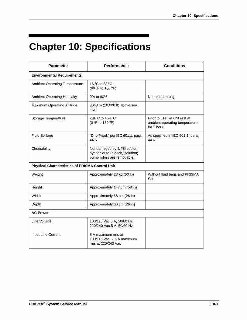
Chapter 10: Specifications
PRISMA® System Service Manual 10-1
Chapter 10: Specifications
Parameter Performance Conditions
Environmental Requirements
Ambient Operating Temperature 16 oC to 38 oC(60 oF to 100 oF)
Ambient Operating Humidity 0% to 90% Non-condensing
Maximum Operating Altitude 3048 m (10,000 ft) above sea level
Storage Temperature -18 oC to +54 oC(0 oF to 130 oF)
Prior to use, let unit rest at ambient operating temperature for 1 hour.
Fluid Spillage “Drip Proof,” per IEC 601.1, para. 44.6
As specified in IEC 601.1, para. 44.6
Cleanability Not damaged by 1/4% sodium hypochlorite (bleach) solution; pump rotors are removable.
Physical Characteristics of PRISMA Control Unit
Weight Approximately 23 kg (50 lb) Without fluid bags and PRISMA Set
Height Approximately 147 cm (58 in)
Width Approximately 66 cm (26 in)
Depth Approximately 66 cm (26 in)
AC Power
Line Voltage
Input Line Current
100/115 Vac 5 A, 50/60 Hz;220/240 Vac 5 A, 50/60 Hz
5 A maximum rms at100/115 Vac; 2.5 A maximum rms at 220/240 Vac
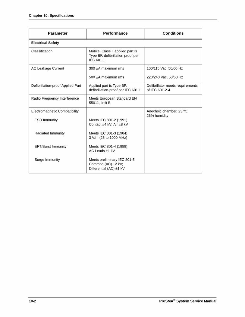
Chapter 10: Specifications
Electrical Safety
Classification Mobile, Class I, applied part is Type BF, defibrillation proof per IEC 601.1
AC Leakage Current 300 µA maximum rms
500 µA maximum rms
100/115 Vac, 50/60 Hz
220/240 Vac, 50/60 Hz
Defibrillation-proof Applied Part Applied part is Type BF, defibrillation-proof per IEC 601.1
Defibrillator meets requirements of IEC 601-2-4
Radio Frequency Interference Meets European Standard EN 55011, limit B
Electromagnetic Compatibility
ESD Immunity
Radiated Immunity
EFT/Burst Immunity
Surge Immunity
Meets IEC 801-2 (1991)Contact ±4 kV; Air ±8 kV
Meets IEC 801-3 (1984)3 V/m (25 to 1000 MHz)
Meets IEC 801-4 (1988)AC Leads ±1 kV
Meets preliminary IEC 801-5Common (AC) ±2 kV; Differential (AC) ±1 kV
Anechoic chamber, 23 oC, 26% humidity
Parameter Performance Conditions
10-2 PRISMA® System Service Manual

Chapter 10: Specifications
Anticoagulant Settings
Anticoagulant Continuous Delivery Rate
Range
Increment
Accuracy
User settable; 0, or 0.5 to 5.0 ml/hr
0.1 ml/hr
±0.5 ml/hr Use of approved, 20-cc, luer lock syringesa
Anticoagulant Bolus VolumeRange
Increment
Accuracy
User settable; 0, or 0.5 to 5.0 ml
0.1 ml
±0.5 ml
Anticoagulant Bolus FrequencyRange
Increment
User settable; Once every 1 to 24 hours
Note: Immediate option also available in Run mode only.
1 hour
Anticoagulant Bolus Delivery Rate
1 ml/≤20 sec Use of approved, 20-cc, luer lock syringesa
Flow Rate Ranges and Accuracy
Blood Flow RateRange
Increment
Accuracy
Return Blood Flow Rate
User settable; 10 to 180 ml/min
5 ml/min
±25% of user-set rate
110 ml/min
Treatment time up to 72 hours.
When Return Blood softkey is pressed
Parameter Performance Conditions
PRISMA® System Service Manual 10-3
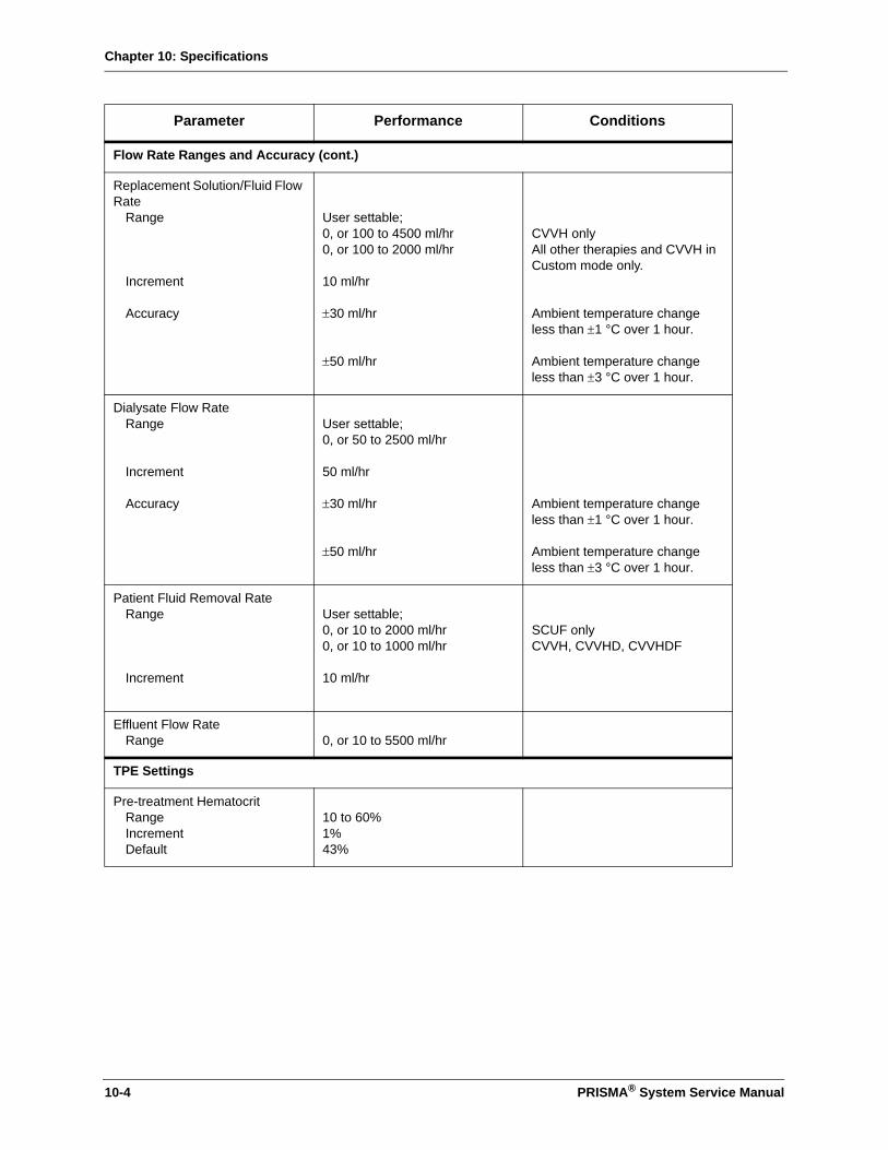
Chapter 10: Specifications
Flow Rate Ranges and Accuracy (cont.)
Replacement Solution/Fluid Flow Rate
Range
Increment
Accuracy
User settable;0, or 100 to 4500 ml/hr0, or 100 to 2000 ml/hr
10 ml/hr
±30 ml/hr
±50 ml/hr
CVVH onlyAll other therapies and CVVH in Custom mode only.
Ambient temperature change less than ±1 °C over 1 hour.
Ambient temperature change less than ±3 °C over 1 hour.
Dialysate Flow RateRange
Increment
Accuracy
User settable; 0, or 50 to 2500 ml/hr
50 ml/hr
±30 ml/hr
±50 ml/hr
Ambient temperature change less than ±1 °C over 1 hour.
Ambient temperature change less than ±3 °C over 1 hour.
Patient Fluid Removal RateRange
Increment
User settable;0, or 10 to 2000 ml/hr0, or 10 to 1000 ml/hr
10 ml/hr
SCUF onlyCVVH, CVVHD, CVVHDF
Effluent Flow RateRange 0, or 10 to 5500 ml/hr
TPE Settings
Pre-treatment HematocritRangeIncrementDefault
10 to 60%1%43%
Parameter Performance Conditions
10-4 PRISMA® System Service Manual
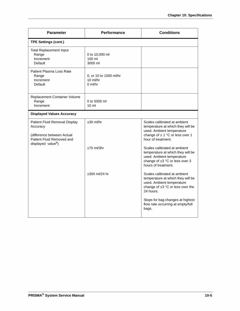
Chapter 10: Specifications
TPE Settings (cont.)
Total Replacement InputRangeIncrementDefault
0 to 10,000 ml100 ml3000 ml
Patient Plasma Loss RateRangeIncrementDefault
0, or 10 to 1000 ml/hr10 ml/hr0 ml/hr
Replacement Container VolumeRangeIncrement
0 to 5000 ml10 ml
Displayed Values Accuracy
Patient Fluid Removal Display Accuracy
(difference between Actual Patient Fluid Removed and displayed valueb)
±30 ml/hr
±70 ml/3hr
±300 ml/24 hr
Scales calibrated at ambient temperature at which they will be used. Ambient temperature change of ± 1 °C or less over 1 hour of treatment.
Scales calibrated at ambient temperature at which they will be used. Ambient temperature change of ±3 °C or less over 3 hours of treatment.
Scales calibrated at ambient temperature at which they will be used. Ambient temperature change of ±3 °C or less over the 24 hours.
Stops for bag changes at highest flow rate occurring at empty/full bags.
Parameter Performance Conditions
PRISMA® System Service Manual 10-5
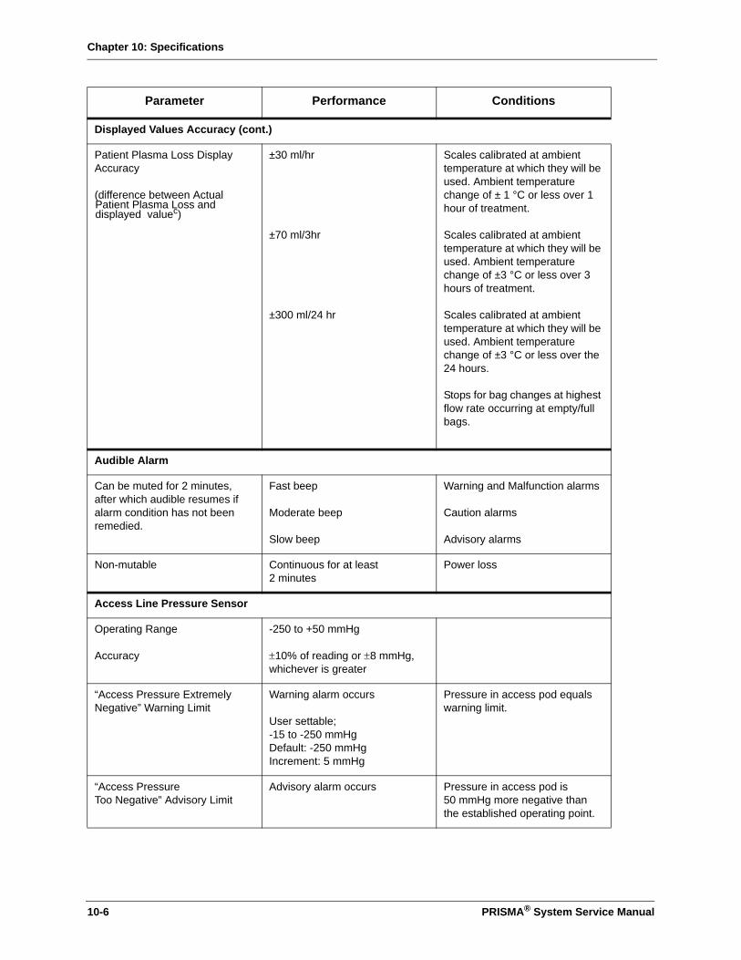
Chapter 10: Specifications
Displayed Values Accuracy (cont.)
Patient Plasma Loss Display Accuracy
(difference between Actual Patient Plasma Loss and displayed valuec)
±30 ml/hr
±70 ml/3hr
±300 ml/24 hr
Scales calibrated at ambient temperature at which they will be used. Ambient temperature change of ± 1 °C or less over 1 hour of treatment.
Scales calibrated at ambient temperature at which they will be used. Ambient temperature change of ±3 °C or less over 3 hours of treatment.
Scales calibrated at ambient temperature at which they will be used. Ambient temperature change of ±3 °C or less over the 24 hours.
Stops for bag changes at highest flow rate occurring at empty/full bags.
Audible Alarm
Can be muted for 2 minutes, after which audible resumes if alarm condition has not been remedied.
Fast beep
Moderate beep
Slow beep
Warning and Malfunction alarms
Caution alarms
Advisory alarms
Non-mutable Continuous for at least 2 minutes
Power loss
Access Line Pressure Sensor
Operating Range
Accuracy
-250 to +50 mmHg
±10% of reading or ±8 mmHg,whichever is greater
“Access Pressure Extremely Negative” Warning Limit
Warning alarm occurs
User settable; -15 to -250 mmHgDefault: -250 mmHgIncrement: 5 mmHg
Pressure in access pod equals warning limit.
“Access PressureToo Negative” Advisory Limit
Advisory alarm occurs Pressure in access pod is 50 mmHg more negative than the established operating point.
Parameter Performance Conditions
10-6 PRISMA® System Service Manual
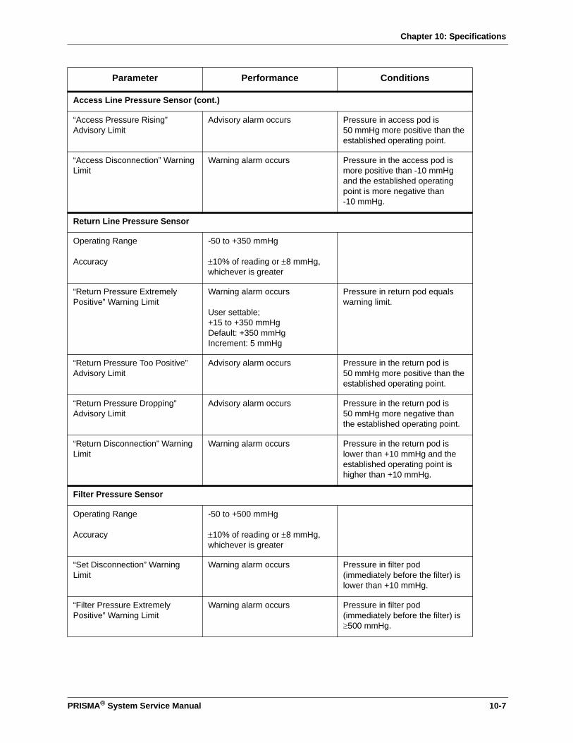
Chapter 10: Specifications
Access Line Pressure Sensor (cont.)
“Access Pressure Rising” Advisory Limit
Advisory alarm occurs Pressure in access pod is 50 mmHg more positive than the established operating point.
“Access Disconnection” Warning Limit
Warning alarm occurs Pressure in the access pod is more positive than -10 mmHg and the established operating point is more negative than -10 mmHg.
Return Line Pressure Sensor
Operating Range
Accuracy
-50 to +350 mmHg
±10% of reading or ±8 mmHg,whichever is greater
“Return Pressure Extremely Positive” Warning Limit
Warning alarm occurs
User settable;
+15 to +350 mmHgDefault: +350 mmHgIncrement: 5 mmHg
Pressure in return pod equals warning limit.
“Return Pressure Too Positive” Advisory Limit
Advisory alarm occurs Pressure in the return pod is 50 mmHg more positive than the established operating point.
“Return Pressure Dropping” Advisory Limit
Advisory alarm occurs Pressure in the return pod is 50 mmHg more negative than the established operating point.
“Return Disconnection” Warning Limit
Warning alarm occurs Pressure in the return pod is lower than +10 mmHg and the established operating point is higher than +10 mmHg.
Filter Pressure Sensor
Operating Range
Accuracy
-50 to +500 mmHg
±10% of reading or ±8 mmHg,whichever is greater
“Set Disconnection” Warning Limit
Warning alarm occurs Pressure in filter pod (immediately before the filter) is lower than +10 mmHg.
“Filter Pressure Extremely Positive” Warning Limit
Warning alarm occurs Pressure in filter pod (immediately before the filter) is≥500 mmHg.
Parameter Performance Conditions
PRISMA® System Service Manual 10-7
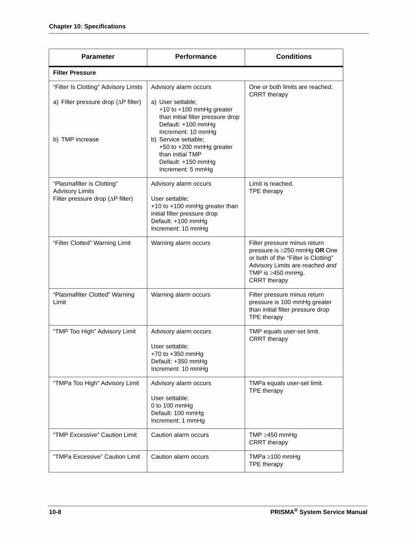
Chapter 10: Specifications
Filter Pressure
“Filter Is Clotting” Advisory Limits
a) Filter pressure drop (∆P filter)
b) TMP increase
Advisory alarm occurs
a) User settable; +10 to +100 mmHg greater than initial filter pressure dropDefault: +100 mmHgIncrement: 10 mmHg
b) Service settable; +50 to +200 mmHg greater than initial TMPDefault: +150 mmHgIncrement: 5 mmHg
One or both limits are reached. CRRT therapy
“Plasmafilter is Clotting” Advisory LimitsFilter pressure drop (∆P filter)
Advisory alarm occurs
User settable; +10 to +100 mmHg greater than initial filter pressure dropDefault: +100 mmHgIncrement: 10 mmHg
Limit is reached. TPE therapy
“Filter Clotted” Warning Limit Warning alarm occurs Filter pressure minus return pressure is ≥250 mmHg OR One or both of the “Filter is Clotting” Advisory Limits are reached and TMP is ≥450 mmHg. CRRT therapy
“Plasmafilter Clotted” Warning Limit
Warning alarm occurs Filter pressure minus return pressure is 100 mmHg greater than initial filter pressure drop TPE therapy
“TMP Too High” Advisory Limit Advisory alarm occurs
User settable;+70 to +350 mmHgDefault: +350 mmHgIncrement: 10 mmHg
TMP equals user-set limit. CRRT therapy
“TMPa Too High” Advisory Limit Advisory alarm occurs
User settable;0 to 100 mmHgDefault: 100 mmHgIncrement: 1 mmHg
TMPa equals user-set limit. TPE therapy
“TMP Excessive” Caution Limit Caution alarm occurs TMP ≥450 mmHg CRRT therapy
“TMPa Excessive” Caution Limit Caution alarm occurs TMPa ≥100 mmHg TPE therapy
Parameter Performance Conditions
10-8 PRISMA® System Service Manual

Chapter 10: Specifications
Effluent Line Pressure Sensor
Operating Range
Accuracy
-350 to +50 mmHg-50 to +350 mmHg
±10% of reading or ±8 mmHg,whichever is greater±13% of reading or ±11 mmHg, whichever is greater
CRRT therapyTPE therapy
CRRT therapy
TPE therapy
“Effluent Pressure Too Negative” Caution limit
Caution alarm occurs Pressure in effluent pod <-50 mmHg TPE therapy
Air Bubble Detector
Macro air detection
Micro air detection
Warning alarm occurs
Warning alarm occurs
One voltage decrease ≥58% of nominal signal level is received from the transducer.d
Voltage decreases of 8% or greater are detected as micro air. The alarm is triggered by a software calculation which includes the blood pump speed and the duration of detected micro air within any 60-second period.
Parameter Performance Conditions
PRISMA® System Service Manual 10-9
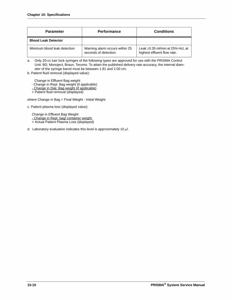
Chapter 10: Specifications
Blood Leak Detector
Minimum blood leak detection Warning alarm occurs within 25 seconds of detection.
Leak ≥0.35 ml/min at 25% Hct, at highest effluent flow rate.
a. Only 20-cc luer lock syringes of the following types are approved for use with the PRISMA Control Unit: BD, Monoject, Braun, Terumo. To attain the published delivery rate accuracy, the internal diam-eter of the syringe barrel must be between 1.81 and 2.00 cm.
b. Patient fluid removal (displayed value):
Change in Effluent Bag weight- Change in Repl. Bag weight (if applicable)- Change in Dial. Bag weight (if applicable)= Patient fluid removal (displayed)
where Change in Bag = Final Weight - Initial Weight
c. Patient plasma loss (displayed value):
Change in Effluent Bag Weight - Change in Repl. bag/ container weight = Actual Patient Plasma Loss (displayed)
d. Laboratory evaluation indicates this level is approximately 10 µl.
Parameter Performance Conditions
10-10 PRISMA® System Service Manual

Appendix A
Appendix A
Note on the combined use of Prisma and the ECG monitoring system
Occasional disturbances have been reported in electrocardiogram (ECG) recording during renal replacement therapy with the Prisma system. These disturbances can appear as artifacts on the ECG trace and may be misinterpreted as abnormal rhythm, atrial flutter, etc. The electrocardiograph can detect an electrical interference caused by rotation of the Prisma blood pump if any electrode has an inadequate contact impedance with the skin. This kind of artifact disappears when the Prisma pumps stop.
To minimize or avoid Prisma interference with ECG recording, it is recommended to follow the ECG supplier's instructions for chronic patient monitoring carefully regarding (1) use of specific electrodes with low contact impedance, and (2) correct application of the electrodes, including appropriate placement of the N electrode.
PRISMA® System Service Manual A-1

Appendix A
This page is left intentionally blank
A-2 PRISMA® System Service Manual

Appendix B: Fluid Balance Description (CRRT)
Appendix B: Fluid Balance Description (CRRT)
This Appendix provides additional information about the PRISMA System's management of patient fluid removal and patient fluid balance during CRRT treatments. Basic information about these topics is provided in Chapter 2 “CRRT & TPE Therapies” subsections “Flow Rates and Anticoagulant Settings”, “Fluid Balance”, Operatings Mode”, “Setup Mode”, “End Mode”.
Flow Rates
The flow rate information entered during the Setup procedure for replacement, dialysate, and patient fluid removal tells the PRISMA Control Unit how quickly or slowly to run its fluid pumps. The pump speeds (rpm) are monitored and automatically adjusted in order to maintain the desired hourly flow rates.
How PRISMA Monitors the Flow Rates
Dialysate, Replacement, and Effluent Fluids
The built-in scales continuously monitor the weight of the dialysate, replacement, and effluent bags and provide information to PRISMA software as to how much fluid the control unit has pumped. The information is subject to the accuracy specifications of the scales. (See Accuracy Specification in Chapter 8: Specifications and at the end of this Appendix).
During operation, software compares the actual bag weights to the expected weights. (The expected weights are continually computed, based on the flow rates that the operator has set.) If the actual weight of a bag varies 20 ml from the expected weight, the control unit stops all fluid pumps and issues an "Incorrect Weight Change" Caution alarm. The alarm usually indicates a problem with solutions not infusing at their expected rates, often due to flow obstructions. (For more information, see "Protecting the Patient from Fluid Imbalance" below.)
How PRISMA Determines “Actual Patient Fluid Removed”
"Actual Patient Fluid Removed" is the net amount of fluid removed from the patient by the PRISMA System during a specified time period.
To determine the Actual Pt. Fluid Removed, PRISMA takes the amount of effluent fluid pumped and subtracts the amount of dialysate fluid and replacement fluids pumped. The below formula applies:
PRISMA® System Service Manual B-1

Appendix B: Fluid Balance Description (CRRT)
Protecting the Patient from Fluid Imbalance
The PRISMA System is designed to provide solute removal from the patient's blood, net fluid removal from the patient's blood, or both. If net fluid removal is not desired, the PRISMA System is designed to operate to maintain a zero fluid balance in the patient's blood (no net fluid loss or gain).
Flow problems in the fluid lines, bags, or pump segments can change the flow rates within the fluid lines and the filter and cause errors in the amount of patient fluid removed. The PRISMA Safety System protects from these situations via alarms that suspend the treatment and alert the operator. Two different Caution alarms are involved: "Incorrect Weight Change Detected" and "Excess Pt. Fluid Loss or Gain." These alarms are described in detail below.
“Incorrect Weight Change” Alarm
Anything that causes a hanging bag's weight to vary from the expected amount by 20 ml causes an "Incorrect Weight Change" Caution alarm. This alarm suspends treatment by stopping the fluid pumps. The blood pump continues to run and circulate the patient's blood through the blood flowpath.
Information reported on the alarm screen helps the operator understand the larger picture related to the patient's fluid balance. This information includes the amount of fluid removal variance within 3 hours that exists and also how much variance is allowed before the Caution: Excess Pt. Fluid Loss or Gain alarm occurs and requires the operator to end the treatment. (See Figure B-1: An "Incorrect Weight Change" Alarm Screen.)
Effluent fluid pumped (ml)
- Dialysate pumped (ml)
- Replacement solution pumped (ml)
= Actual patient fluid removed (ml)
Figure B-1. An “Incorrect Weight Change” Alarm Screen
Amount of patient fluid removal variance that currently exists.Amount of variance allowed within any 3 hours.
B-2 PRISMA® System Service Manual

Appendix B: Fluid Balance Description (CRRT)
Excess Pt. Fluid Removed or gained
When a 20 ml variance triggers an "Incorrect Weight Change" alarm, the Actual Pt. Fluid Removed is 20 ml higher or lower than the target value set by the Pt. Fluid Removal flow rate. This patient fluid removal variance is reported at the top of the alarm screen and is termed "Excess Pt. Fluid Loss or Gain."
If the patient fluid removed is higher than the target patient fluid removal value, an "Excess Pt. Fluid LOSS" is reported. Example: The target patient fluid removal is 60 ml, but the amount removed is 80 ml. Conversely, if the patient fluid removal variance is lower than the target fluid removal value, "Excess Pt. Fluid GAIN" is reported. Example: The target patient fluid removal is 60 ml, but the amount removed is 40 ml. Instead of being removed, the 20 ml has been infused to the patient as an unintended fluid gain.
It is important to note that Displayed Excess Pt. Fluid Loss or Gain is cumulative. Each alarm occurrence may contribute another 20 ml of variance to the cumulative total.
Common Causes of Incorrect Weight Change
Flow obstructions are probably the most frequent cause of Incorrect Weight Change alarms. For example, inadvertently leaving a fluid line clamped, neglecting to break the frangible pins inside a solution bag, or fluid leakage. A swinging or partially supported fluid bag can cause an unexpected bag weight and is another common cause of this alarm. Thirdly, variations in room temperature of ±3°C or more can cause the scales to become inaccurate and result in this alarm.
Remedying the Incorrect Weight Change Alarm
Instructions are provided on the alarm screen and in the Troubleshooting section of this Manual.
The operator should thoroughly investigate and remedy all possible problems before pressing the CONTINUE softkey on the alarm screen. CONTINUE restarts the fluid pumps. If the underlying problem still exists, a 20 ml variance in patient fluid removal occurs with each subsequent occurrence of the alarm.
Unresolved Incorrect Weight Change alarms could result in substantial fluid losses or gains in the patient; however, to prevent this, the PRISMA System limits the amount of fluid removal/gain variance allowed. If this limit is reached, the "Excess Pt. Fluid Loss or Gain" alarm occurs and requires the operator to end the treatment.
"Excess Pt. Fluid Loss or Gain Limit"
A safety limit ensures that excessive fluid cannot be unintentionally removed from or infused to the patient across the semipermeable membrane of the filter. This limit protects the patient during abnormal conditions in which the effluent pump can be manually commanded to run.
To correlate the safety limit to the individual patient, during the Setup procedure, the operator is asked to enter the physician-prescribed "Excess Pt. Fluid Loss or Gain Limit." 1
1. The "Excess Pt. Fluid Loss or Gain Limit" must be prescribed by the physician. The value prescribed should be based upon the patient's ability to tolerate potential fluid imbalance.
PRISMA® System Service Manual B-3
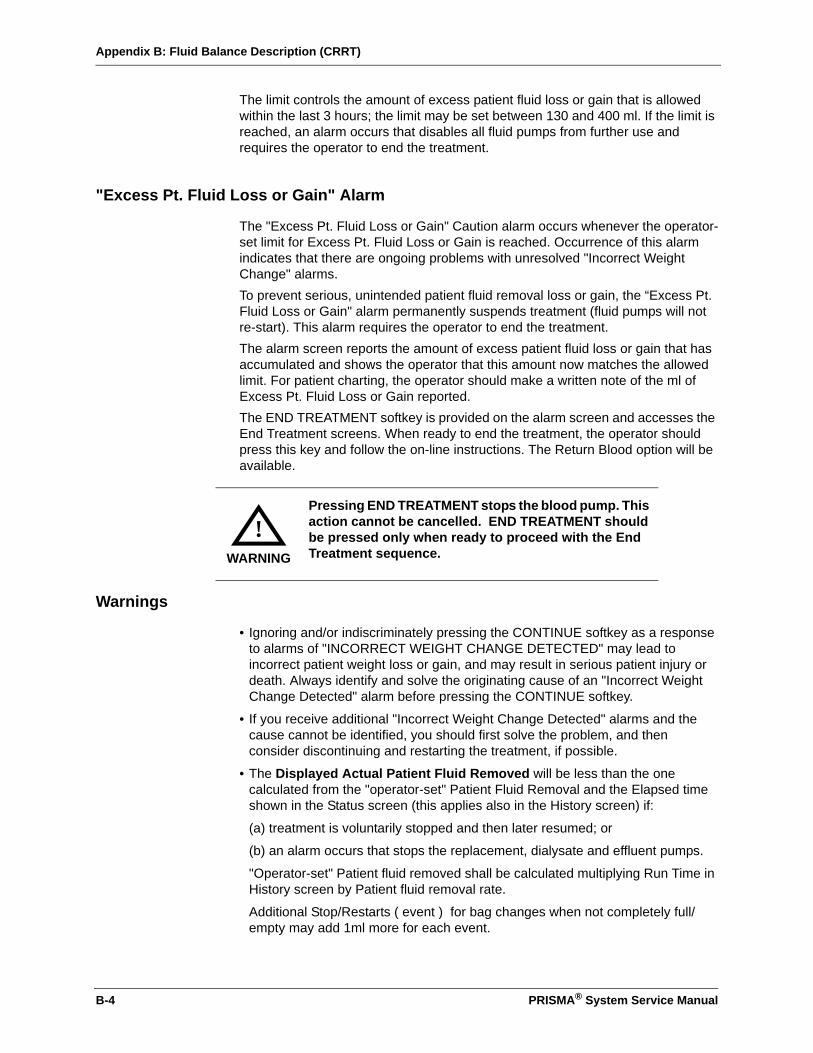
Appendix B: Fluid Balance Description (CRRT)
The limit controls the amount of excess patient fluid loss or gain that is allowed within the last 3 hours; the limit may be set between 130 and 400 ml. If the limit is reached, an alarm occurs that disables all fluid pumps from further use and requires the operator to end the treatment.
"Excess Pt. Fluid Loss or Gain" Alarm
The "Excess Pt. Fluid Loss or Gain" Caution alarm occurs whenever the operator-set limit for Excess Pt. Fluid Loss or Gain is reached. Occurrence of this alarm indicates that there are ongoing problems with unresolved "Incorrect Weight Change" alarms.To prevent serious, unintended patient fluid removal loss or gain, the “Excess Pt. Fluid Loss or Gain" alarm permanently suspends treatment (fluid pumps will not re-start). This alarm requires the operator to end the treatment.The alarm screen reports the amount of excess patient fluid loss or gain that has accumulated and shows the operator that this amount now matches the allowed limit. For patient charting, the operator should make a written note of the ml of Excess Pt. Fluid Loss or Gain reported.The END TREATMENT softkey is provided on the alarm screen and accesses the End Treatment screens. When ready to end the treatment, the operator should press this key and follow the on-line instructions. The Return Blood option will be available.
Warnings
• Ignoring and/or indiscriminately pressing the CONTINUE softkey as a response to alarms of "INCORRECT WEIGHT CHANGE DETECTED" may lead to incorrect patient weight loss or gain, and may result in serious patient injury or death. Always identify and solve the originating cause of an "Incorrect Weight Change Detected" alarm before pressing the CONTINUE softkey.
• If you receive additional "Incorrect Weight Change Detected" alarms and the cause cannot be identified, you should first solve the problem, and then consider discontinuing and restarting the treatment, if possible.
• The Displayed Actual Patient Fluid Removed will be less than the one calculated from the "operator-set" Patient Fluid Removal and the Elapsed time shown in the Status screen (this applies also in the History screen) if:
(a) treatment is voluntarily stopped and then later resumed; or
(b) an alarm occurs that stops the replacement, dialysate and effluent pumps.
"Operator-set" Patient fluid removed shall be calculated multiplying Run Time in History screen by Patient fluid removal rate.
Additional Stop/Restarts ( event ) for bag changes when not completely full/empty may add 1ml more for each event.
Pressing END TREATMENT stops the blood pump. This action cannot be cancelled. END TREATMENT should be pressed only when ready to proceed with the End Treatment sequence.WARNING
!
B-4 PRISMA® System Service Manual

Appendix B: Fluid Balance Description (CRRT)
Precautions
• Prior to using the PRISMA Control Unit let the unit rest at ambient operating temperature for 1 hour.
• The accuracy of the PRISMA Control Unit depends on accurate scale and pressure calibration. Ensure that scales and pressure sensors are accurately calibrated. Calibrations must be performed by a trained and qualified person. Calibration instructions are provided in this PRISMA System Service Manual.
• If the room temperature changes by more than ± 3° C (5.4 °F), STOP the treatment and call service to recalibrate the scales. Do not continue to use the PRISMA Control Unit until the scales are recalibrated.
• As treatment proceeds, carefully monitor patient fluid balance levels and all the I/O Data on the Status and History screens. Fluid balance monitoring should include frequent totaling of patient fluid input/output and periodic verification of the patient's weight using an independent (non-PRISMA) means.
Table B-1: Accuracy Specifications
Parameter Performance Conditions
Displayed Values Accuracy
Patient Fluid Removal Display Accuracy
(difference between actual fluid removed and displayed valuea)
a. Patient fluid removal (displayed value):
Change in Effluent Bag weight- Change in Repl. Bag weight (if applicable)- Change in Dial. Bag weight (if applicable)
_________________________________________= Patient fluid removal (displayed)
where Change in Bag = Final Weight - Initial Weight
±30 ml/hr
±70 ml/3hr
±300 ml/24 hr
Scales calibrated at ambient temperature at which they will be used. Ambient temperature change of ± 1 °C or less over 1 hour of treatment.
Scales calibrated at ambient temperature at which they will be used. Ambient temperature change of ±3 °C or less over 3 hours of treatment.
Scales calibrated at ambient temperature at which they will be used. Ambient temperature change of ±3 °C or less over the 24 hours.
Stops for bag changes at highest flow rate occurring at empty/full bags.
PRISMA® System Service Manual B-5

Appendix B: Fluid Balance Description (CRRT)
This page is left intentionally blank
B-6 PRISMA® System Service Manual

Appendix C: Fluid Balance Description (TPE)
Appendix C: Fluid Balance Description (TPE)
This Appendix provides additional information about the PRISMA System's management of patient plasma loss and patient plasma balance during TPE treatment. Basic information about these topics is provided in Chapter 2 “CRRT & TPE Therapies” subsections “TPE Prescriptions, Flow Rates and Anticoagulant Settings”, “Plasma Balance” Operatings Mode”, “Setup Mode”, “End Mode”.
Flow Rates
The flow rate information entered during the Setup procedure for replacement, and patient plasma loss tells the PRISMA Control Unit how quickly or slowly to run its fluid pumps. The pump speeds (rpm) are monitored and automatically adjusted in order to maintain the desired hourly flow rates.
How PRISMA Monitors the Flow Rates
Replacement, and Effluent Fluids
The built-in scales continuously monitor the weight of the replacement, and effluent bags and provide information to PRISMA software as to how much fluid the control unit has pumped. The information is subject to the accuracy specifications of the scales. (See Accuracy Specification in Chapter 10: Specifications and at the end of this Appendix).
During operation, software compares the actual bag weights to the expected weights. (The expected weights are continually computed, based on the flow rates that the operator has set.) If the actual weight of a bag varies 20 ml from the expected weight, the control unit stops all fluid pumps and issues an "Incorrect Weight Change" Caution alarm. The alarm usually indicates a problem with solutions not infusing at their expected rates, often due to flow obstructions.
(For more information, see "Protecting the Patient from Fluid Imbalance" below.)
How PRISMA Determines “Actual Patient Plasma Loss”
"Actual Patient Plasma Loss" is the net amount of plasma removed from the patient by the PRISMA System during a specified time period.
To determine the Actual Patient Plasma Loss, PRISMA takes the amount of effluent fluid pumped and subtracts the amount of replacement fluid pumped. The below formula applies:
PRISMA® System Service Manual C-1
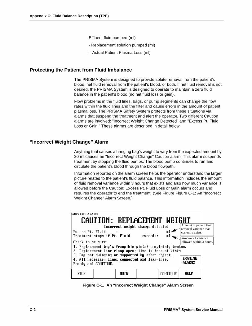
Appendix C: Fluid Balance Description (TPE)
Protecting the Patient from Fluid Imbalance
The PRISMA System is designed to provide solute removal from the patient's blood, net fluid removal from the patient's blood, or both. If net fluid removal is not desired, the PRISMA System is designed to operate to maintain a zero fluid balance in the patient's blood (no net fluid loss or gain).
Flow problems in the fluid lines, bags, or pump segments can change the flow rates within the fluid lines and the filter and cause errors in the amount of patient plasma loss. The PRISMA Safety System protects from these situations via alarms that suspend the treatment and alert the operator. Two different Caution alarms are involved: "Incorrect Weight Change Detected" and "Excess Pt. Fluid Loss or Gain." These alarms are described in detail below.
“Incorrect Weight Change” Alarm
Anything that causes a hanging bag's weight to vary from the expected amount by 20 ml causes an "Incorrect Weight Change" Caution alarm. This alarm suspends treatment by stopping the fluid pumps. The blood pump continues to run and circulate the patient's blood through the blood flowpath.
Information reported on the alarm screen helps the operator understand the larger picture related to the patient's fluid balance. This information includes the amount of fluid removal variance within 3 hours that exists and also how much variance is allowed before the Caution: Excess Pt. Fluid Loss or Gain alarm occurs and requires the operator to end the treatment. (See Figure Figure C-1: An "Incorrect Weight Change" Alarm Screen.)
Effluent fluid pumped (ml)
- Replacement solution pumped (ml)
= Actual Patient Plasma Loss (ml)
Figure C-1. An “Incorrect Weight Change” Alarm Screen
Amount of patient fluid removal variance thatcurrently exists.
Amount of variance allowed within 3 hours.
C-2 PRISMA® System Service Manual

Appendix C: Fluid Balance Description (TPE)
Excess Pt. Fluid Removed or gained
When a 20 ml variance triggers an "Incorrect Weight Change" alarm, the Actual Patient Plasma Loss is 20 ml higher or lower than the target value set by the Patient Plasma Loss rate. This patient fluid removal variance is reported at the top of the alarm screen and is termed "Excess Pt. Fluid Loss or Gain."
If the patient plasma loss is higher than the target patient fluid removal value, an "Excess Pt. Fluid LOSS" is reported. Example: The target patient plasma loss is 60 ml, but the amount removed is 80 ml. Conversely, if the patient plasma loss variance is lower than the target fluid plasma loss value, "Excess Pt. Fluid GAIN" is reported. Example: The target patient plasma loss is 60 ml, but the amount removed is 40 ml. Instead of being removed, the 20 ml has been infused to the patient as an unintended fluid gain.
It is important to note that Displayed Excess Pt. Fluid Loss or Gain is cumulative. Each alarm occurrence may contribute another 20 ml of variance to the cumulative total.
Common Causes of Incorrect Weight Change
Flow obstructions are probably the most frequent cause of Incorrect Weight Change alarms. For example, inadvertently leaving a fluid line clamped, neglecting to break the frangible pins inside a solution bag, or fluid leakage. A swinging or partially supported fluid bag can cause an unexpected bag weight and is another common cause of this alarm. Thirdly, variations in room temperature of ±3°C or more can cause the scales to become inaccurate and result in this alarm.
Remedying the Incorrect Weight Change Alarm
Instructions are provided on the alarm screen and in the Troubleshooting section of this Manual.
The operator should thoroughly investigate and remedy all possible problems before pressing the CONTINUE softkey on the alarm screen. CONTINUE restarts the fluid pumps. If the underlying problem still exists, a 20 ml variance in patient plasma loss occurs with each subsequent occurrence of the alarm.
Unresolved Incorrect Weight Change alarms could result in substantial fluid losses or gains in the patient; however, to prevent this, the PRISMA System limits the amount of fluid removal/gain variance allowed. If this limit is reached, the "Excess Pt. Fluid Loss or Gain" alarm occurs and requires the operator to end the treatment.
"Excess Pt. Fluid Loss or Gain Limit"
A safety limit ensures that excessive fluid/plasma cannot be unintentionally removed from or infused to the patient across the semipermeable membrane of the filter. This limit protects the patient during abnormal conditions in which the effluent pump can be manually commanded to run.
To correlate the safety limit to the individual patient, during the Setup procedure, the operator is asked to enter the physician-prescribed "Excess Pt. Fluid Loss or Gain Limit." 1
1. The "Excess Pt. Fluid Loss or Gain Limit" must be prescribed by the physician. The value prescribed should be based upon the patient's ability to tolerate potential fluid imbalance.
PRISMA® System Service Manual C-3
Appendix C: Fluid Balance Description (TPE)
The limit controls the amount of excess patient fluid loss or gain that is allowed within the last 3 hours; the limit may be set between 130 and 400 ml. If the limit is reached, an alarm occurs that disables all fluid pumps from further use and requires the operator to end the treatment.
"Excess Pt. Fluid Loss or Gain" Alarm
The "Excess Pt. Fluid Loss or Gain" Caution alarm occurs whenever the operator-set limit for Excess Pt. Fluid Loss or Gain is reached. Occurrence of this alarm indicates that there are ongoing problems with unresolved "Incorrect Weight Change" alarms.To prevent serious, unintended patient plasma loss or gain, the “Excess Pt. Fluid Loss or Gain" alarm permanently suspends treatment (fluid pumps will not re-start). This alarm requires the operator to end the treatment.The alarm screen reports the amount of excess patient plasma loss or gain that has accumulated and shows the operator that this amount now matches the allowed limit. For patient charting, the operator should make a written note of the ml of Excess Pt. Fluid Loss or Gain reported.The END TREATMENT softkey is provided on the alarm screen and accesses the End Treatment screens. When ready to end the treatment, the operator should press this key and follow the on-line instructions. The Return Blood option will be available.
Warnings
• Ignoring and/or indiscriminately pressing the CONTINUE softkey as a response to alarms of "INCORRECT WEIGHT CHANGE DETECTED" may lead to incorrect patient weight loss or gain, and may result in serious patient injury or death. Always identify and solve the originating cause of an "Incorrect Weight Change Detected" alarm before pressing the CONTINUE softkey.
• If you receive additional "Incorrect Weight Change Detected" alarms and the cause cannot be identified, you should first solve the problem, and then consider discontinuing and restarting the treatment, if possible.
• The Displayed Actual Patient Plasma Loss will be less than the one calculated from the "operator-set" Patient Plasma Loss and the Elapsed time shown in the Status screen (this applies also in the History screen) if:
(a) treatment is voluntarily stopped and then later resumed; or
(b) an alarm occurs that stops the replacement, dialysate and effluent pumps.
"Operator-set" Patient Plasma Removed shall be calculated multiplying Run Time in History screen by Patient fluid removal rate.
Additional Stop/Restarts ( event ) for bag changes when not completely full/empty may add 1ml more for each event.
Pressing END TREATMENT stops the blood pump. This action cannot be cancelled. END TREATMENT should be pressed only when ready to proceed with the End Treatment sequence.WARNING
!
C-4 PRISMA® System Service Manual

Appendix C: Fluid Balance Description (TPE)
Precautions
• Prior to using the PRISMA Control Unit let the unit rest at ambient operating temperature for 1 hour.
• The accuracy of the PRISMA Control Unit depends on accurate scale and pressure calibration. Ensure that scales and pressure sensors are accurately calibrated. Calibrations must be performed by a trained and qualified person. Calibration instructions are provided in this PRISMA System Service Manual.
• If the room temperature changes by more than ± 3° C (5.4 °F), STOP the treatment and call service to recalibrate the scales. Do not continue to use the PRISMA Control Unit until the scales are recalibrated.
• As treatment proceeds, carefully monitor patient plasma balance levels and all the I/O Data on the Status and History screens. Fluid balance monitoring should include frequent totaling of patient fluid input/output and periodic verification of the patient's weight using an independent (non-PRISMA) means.
Table B-1: Accuracy Specifications
Parameter Performance Conditions
Displayed Values Accuracy
Patient Plasma Loss Display Accuracy
(difference between actual Patient Plasma Loss and displayed valuea)
a. Patient Plasma Loss (displayed value):
Change in Effluent Bag weight- Change in Repl. bag/container weight_________________________________________= Actual Patient Plasma Loss (displayed)
±30 ml/hr
±70 ml/3hr
±300 ml/24 hr
Scales calibrated at ambient temperature at which they will be used. Ambient temperature change of ± 1 °C or less over 1 hour of treatment.
Scales calibrated at ambient temperature at which they will be used. Ambient temperature change of ±3 °C or less over 3 hours of treatment.
Scales calibrated at ambient temperature at which they will be used. Ambient temperature change of ±3 °C or less over the 24 hours.
Stops for bag changes at highest flow rate occurring at empty/full bags.
PRISMA® System Service Manual C-5

Appendix C: Fluid Balance Description (TPE)
This page is left intentionally blank
C-6 PRISMA® System Service Manual

Index
Index
AAccess membrane pressure (TMPa) . . . . . . . . . . . . 2-59Access pressure sensor
See pressure sensorsAccessory SP394 . . . . . . . . . . . . . . . . . . . . . . . . . . . 2-42Actual plasma loss . . . . . . . . . . . . . . . . . . . . . . . . . . 2-37Advisory alarm description . . . . . . . . . . . . . . . . . . . . 6-10Air bubble detector . . . . . . . . . . . . . . . . . . . . . . 1-6, 5-16
electronic description . . . . . . . . . . 3-1, 3-2, 3-12, 3-14troubleshooting . . . . . . . . . . . . . . . . . . . . . . 6-61, 6-62verification. . . . . . . . . . . . . . . . . . . . . . . . . . . . . . 6-108
Air pump . . . . . . . . . . . . . . . . . . . . . . . . . . . . . . 3-1, 3-17Alarm lamps
See status lightsAlarms
priorities . . . . . . . . . . . . . . . . . . . . . . . . . . . . . . . . 6-11Analog CCA . . . . . . . . . . . . 1-8, 3-1, 3-3, 3-6, 3-25, 3-28
See also Chapter 9, SchematicsAnticoagulant syringe
installation (CRRT) . . . . . . . . . . . . . . . . . . . 2-22, 2-24installation (TPE). . . . . . . . . . . . . . . . . . . . . 2-52, 2-54recommended . . . . . . . . . . . . . . . . . . . . . . . 2-23, 2-53See also syringe pump
ARPS CCASee also Chapter 9, Schematics
Audible alarm verification . . . . . . . . . . . . . . . . . . . . 6-103Automatic reposition system (ARPS) . . . . . . . . . 1-8, 1-9
air pump . . . . . . . . . . . . . . . . . . . . . . . . . . . 3-17, 5-22ARPS CCA . . . . . . . . . . . . . . . . . . . . . . . . . . . . . . . 3-1electronic description . . . . . . . . . . . . . .3-3, 3-17, 3-19maintenance . . . . . . . . . . . . . . . . . . . . . . . . . . . . . . 7-5pressure transducer . . . . . . . . . . . . . . . . . . . . . . . . 3-1reposition sequence . . . . . . . . . . . . . . . . . . . . . . . 3-17troubleshooting . . . . . . . . . . . . . . . . . . . . . . 6-71, 6-73valve drivers . . . . . . . . . . . . . . . . . . . . .3-1, 3-17, 3-18
BBB memory failure
restoring settings. . . . . . . . . . . . . . . . . . . . . . . . . . 7-21troubleshooting . . . . . . . . . . . . . . . . . . . . . . . . . . . 6-23
BBRAMsrestoring settings. . . . . . . . . . . . . . . . . . . . . . . . . . 7-21
Blank screen. . . . . . . . . . . . . . . . . . . . . .2-11, 2-40, 6-68Blood flow rate
limits (CRRT). . . . . . . . . . . . . . . . . . . . . . . . . . . . . 2-21Blood leak detector . . . . . . . . . . . . . . . . . . . . . . . . . . . 1-6
electronic description . . . . . . . . . 3-1, 3-12, 3-15, 3-16maintenance . . . . . . . . . . . . . . . . . . . . . . . . . . . . . . 7-1normalization. . . . . . . . . . . . . . . . . . . . . . . . . . . . . 3-16re-normalize (TPE) . . . . . . . . . . . . . . . . . . . . . . . . 2-46troubleshooting . . . . . . . . . . . . . . . . . . . . . . 6-24, 6-29verification. . . . . . . . . . . . . . . . . . . . . . . . . . . . . . 6-109
Blood pump . . . . . . . . . . . . . . . . . . . . . . . . . . . . 1-5,10-9electronic description . . . . . . . . . .3-1, 3-13, 3-14, 3-21returning blood (CRRT) . . . . . . . . . . . . . . . . . . . . 2-17returning blood (TPE) . . . . . . . . . . . . . . . . . . . . . 2-47troubleshooting . . . . . . . . . . . . . . . . . . . . . . 6-63, 6-64
CCartridge carrier . . . . . . . . . . . . . . . . . . . . . . . . 1-6, 6-65
troubleshooting . . . . . . . . . . . . . . . . . . . . . . . . . . 6-65Cartridge loader. . . . . . . . . . . . . . . . . . . . . . . . . 3-1, 3-23Caution alarm description . . . . . . . . . . . . . . . . . . . . . 6-9Change set
CRRT. . . . . . . . . . . . . . . . . . . . . . . . . . . . . . . . . . 2-17TPE . . . . . . . . . . . . . . . . . . . . . . . . . . . . . . . . . . . 2-47
Changing bagsCRRT. . . . . . . . . . . . . . . . . . . . . . . . . . . . . . . . . . 2-25TPE . . . . . . . . . . . . . . . . . . . . . . . . . . . . . . . 2-54, 2-55
Checksum interruptedtroubleshooting . . . . . . . . . . . . . . . . . . . . . . . . . . 6-25
Clear alarms . . . . . . . . . . . . . . . . . . . . . . . . . . . . . . . 5-3Clock . . . . . . . . . . . . . . . . . . . . . . . . . . . . . . . . . . . . . 5-2Clotting
filter pressure drop (CRRT) . . . . . . . . . . . . . . . . . 2-30filter pressure drop (TPE) . . . . . . . . . . . . . . . . . . 2-60in set (CRRT). . . . . . . . . . . . . . . . . . . . . . . . . . . . 2-19in set (TPE) . . . . . . . . . . . . . . . . . . . . . . . . . 2-49, 2-60troubleshooting (CRRT). . . . . . . . . . . . . . . . . . . . 6-45
Command pathtroubleshooting . . . . . . . . . . . . . . . . . . . . . . . . . . 6-26
Controller CCA . . . . . . . . . . 1-8, 3-1, 3-3, 3-9, 3-9, 3-11See also Chapter 9, Schematicswatch dog . . . . . . . . . . . . . . . . . . . . . . . . . . . 3-11, 4-1
CRRTchanging to TPE . . . . . . . . . . . . . . . . . . . . . . . . . 2-13current values, default values . . . . . . . . . . . . . . . . 2-5custom mode . . . . . . . . . . . . . . . . . . . . . . . . . . . . 2-20end mode. . . . . . . . . . . . . . . . . . . . . . . . . . . 2-17, 2-20filter pressure drop. . . . . . . . . . . . . . . . . . . . . . . . 2-30fluid balance. . . . . . . . . . . . . . . . . . . . . . . . . . . 2-7, 2-9fluid removal rate . . . . . . . . . . . . . . . . . . . . . . . 2-6, 2-7installing set . . . . . . . . . . . . . . . . . . . . . . . . . . . . . 2-14pressure monitoring . . . . . . . . . . . . . . . . . . . 2-25, 2-31temporary disconnection . . . . . . . . . . . . . . . . . . . 2-19TMP . . . . . . . . . . . . . . . . . . . . . . . . . . . . . . . . . . . 2-29user-controllable settings. . . . . . . . . . . . . . . . . . . 2-20
CRRT operating screens. . . . . . . . . . . . . . . . . . . . . 2-15CRRT operation . . . . . . . . . . . . . . . . . . . . . . . 2-11, 2-25CRRT set
cartridge. . . . . . . . . . . . . . . . . . . . . . . . . . . . . . . . . 2-1diagram . . . . . . . . . . . . . . . . . . . . . . . . . . . . . . . . . 2-3filter . . . . . . . . . . . . . . . . . . . . . . . . . . . . . . . . . . . . 2-1installing. . . . . . . . . . . . . . . . . . . . . . . . . . . . . . . . 2-14pressure pods . . . . . . . . . . . . . . . . . . . . . . . . . . . . 2-1sample sites. . . . . . . . . . . . . . . . . . . . . . . . . . . . . . 2-1
Custom modedefault settings (CRRT) . . . . . . . . . . . . . . . . . . . . 2-20default settings (TPE) . . . . . . . . . . . . . . . . . . . . . 2-50user-controllable settings (CRRT) . . . . . . . . . . . . 2-20user-controllable settings (TPE) . . . . . . . . . . . . . 2-50
CVVH (continuous veno-venous hemofiltration) . . . . 1-2CVVHD (continuous veno-venous hemodialysis) . . . 1-2CVVHDF (continuous veno-venous hemodiafiltration)1-2
PRISMA® System Service Manual Index-1
Index
DDefault settings
CRRT . . . . . . . . . . . . . . . . . . . . . . . . . . . . . . . . . . 2-20TPE . . . . . . . . . . . . . . . . . . . . . . . . . . . . . . . . . . . . 2-50
Default valuesCRRT . . . . . . . . . . . . . . . . . . . . . . . . . . . . . . . . . . . 2-4TPE . . . . . . . . . . . . . . . . . . . . . . . . . . . . . . . . . . . . 2-34
Detector CCA . . . . . . . . . . . . . . 1-8, 3-1, 3-3, 3-12, 3-16 See also Chapter 9, SchematicsDialysate. . . . . . . . . . . . . . . . . . . . . . . . . . . .1-2, 1-3, 1-5Dialysate pump. . . . . . . . . . . . . . . . . . . . . . .1-5, 1-6, 3-1
electronic description . . . . . . . . . . . . . . . . . . . . . . 3-21troubleshooting . . . . . . . . . . . . . . . . . . . . . . 6-63, 6-64
Diaphragm reposition procedureCRRT . . . . . . . . . . . . . . . . . . . . . . . . . . . . . 6-89, 6-91TPE . . . . . . . . . . . . . . . . . . . . . . . . . . . . . . . 6-93, 6-95
Display . . . . . . . . . . . . . . . . . . . . . . . . . . . . . . . . 1-5, 3-3See also touchscreen, softkeys, blank screentroubleshooting . . . . . . . . . . . . . . . . . . . . . . . . . . . 6-68
Display driver . . . . . . . . . . . . . . . . . . . . . . . . . . . . . . . 3-4DPRAM failure
troubleshooting . . . . . . . . . . . . . . . . . . . . . . . . . . . 6-27Driver CCA . . . . . . . . . . . . . . . . . . . . . 1-8, 3-1, 3-3, 3-20 See Chapter 9, Schematics
EECG monitoring system . . . . . . . . . . . . . . . . . . . . . . .A-1Effluent bag . . . . . . . . . . . . . . . . . . . . . . . . . . . . . . . . 1-5Effluent line. . . . . . . . . . . . . . . . . . . . . . . . . . . . . . . . . 1-6Effluent pressure sensor
See pressure sensorsEffluent pump . . . . . . . . . . . . . . . . . . . . . . . . . . . 1-2, 1-5
electronic description . . . . . . . . . . . . . .3-1, 3-20, 3-21TPE . . . . . . . . . . . . . . . . . . . . . . . . . . . . . . . . . . . . . 1-7troubleshooting . . . . . . . . . . . . . . . . . . . . . . 6-63, 6-64ultrafiltration rate . . . . . . . . . . . . . . . . . . . . . . . . . . . 2-7
EPROMs. . . . . . . . . . . . . . . . . . . . . . . . . . . . . . . . . . . 3-3Events history . . . . . . . . . . . . . . . . . . . . . . . . . . 2-9, 2-38Examine alarms . . . . . . . . . . . . . . . . . . . . . . . . . . . . . 5-3
CRRT . . . . . . . . . . . . . . . . . . . . . . . . . . . . . . . . . . 2-12TPE . . . . . . . . . . . . . . . . . . . . . . . . . . . . . . . . . . . . 2-41
Examine alarms softkey . . . . . . . . . . . . . . . . . . . . . . 6-11
FFailure codes . . . . . . . . . . . . . . . . . . . . . . . . . . . . . . 6-76Fan . . . . . . . . . . . . . . . . . . . . . . . . . . . 1-7, 1-8, 3-1, 3-24Filter clotting limits . . . . . . . . . . . . . . . . . . . . . . 2-21, 5-2Filter clotting troubleshooting (CRRT) . . . . . . . . . . . 6-45Filter pressure drop
CRRT . . . . . . . . . . . . . . . . . . . . . . . . . . . . . . . . . . 2-30TMP (CRRT) . . . . . . . . . . . . . . . . . . . . . . . . . . . . . 2-29TMPa (TPE) . . . . . . . . . . . . . . . . . . . . . . . . . . . . . 2-59
Filter pressure sensorSee pressure sensors
Flow rate. . . . . . . . . . . . . . . . . . . . . . . . . . . . . . . . . . . 1-5Flow rates, anticoagulation settings (CRRT) . . . . . . . 2-5Flow rates, anticoagulation settings (TPE) . . . . . . . . 2-35Fluid removal (CRRT)
actual . . . . . . . . . . . . . . . . . . . . . . . . . . . . . . . . . . . 2-7
adjusting . . . . . . . . . . . . . . . . . . . . . . . . . . . . . . . . 2-6effluent pump control . . . . . . . . . . . . . . . . . . . . . . . 2-7limits. . . . . . . . . . . . . . . . . . . . . . . . . . . . . . . . . . . 2-22measuring . . . . . . . . . . . . . . . . . . . . . . . . . . . . . . . 2-7net . . . . . . . . . . . . . . . . . . . . . . . . . . . . . . . . . . . . . 2-6replacement solutions . . . . . . . . . . . . . . . . . . . . . . 2-7unaccounted . . . . . . . . . . . . . . . . . . . . . . . . . . . . . 2-6
Fluid volumeI/O data . . . . . . . . . . . . . . . . . . . . . . . . . . . . . . . . . 2-8
Front panel components . . . . . . . . . . . . . . . . . . . . . . 1-4Fuses. . . . . . . . . . . . . . . . . . . . . . . . . . . . . . . . . . . . . 3-2
HHall effect sensor. . . . . . . . . . . . . . . . . . . . . . . 3-22, 6-64Hemodiafiltration . . . . . . . . . . . . . . . . . . . . . . . . . . . . 1-3Hemodialysis . . . . . . . . . . . . . . . . . . . . . . . . . . . . . . . 1-2Hemofiltration . . . . . . . . . . . . . . . . . . . . . . . . . . . . . . 1-2History
deleting patient data (CRRT) . . . . . . . . . . . . . . . . 2-10deleting patient data (TPE) . . . . . . . . . . . . . . . . . 2-39last treatment (CRRT) . . . . . . . . . . . . . . . . . . . . . 2-10last treatment (TPE). . . . . . . . . . . . . . . . . . . . . . . 2-39
II/O
data . . . . . . . . . . . . . . . . . . . . . . . . . . . . . . . . . . . . 2-8history . . . . . . . . . . . . . . . . . . . . . . . . . . . . . . . . . . 2-9period. . . . . . . . . . . . . . . . . . . . . . . . . . . . . . . . . . . 2-8
ID, PRISMA . . . . . . . . . . . . . . . . . . . . . . . . . . . . . . . 5-10Illustated Parts
See Chapter 8
JJumpers Configuration . . . . . . . . . . . . . . . . . . . . . . 1-10
LLanguage
change in run and setup modes . . . . . . . . . . 2-5, 2-34settings . . . . . . . . . . . . . . . . . . . . . . . . . . . . . . . . 2-22
Last treatment history data (CRRT) . . . . . . . . . . . . 2-10Last treatment history data (TPE) . . . . . . . . . . . . . . 2-39Linear actuator . . . . . . . . . . . . . . . . . . . . . . . . . . . . 6-65Load Cell . . . . . . . . . . . . . . . . . . . . . . . . . . . . . . . . . 3-28LVDT . . . . . . . . . . . . . . . . . . . . . . . . . . . . . . . . . . . . 3-27
MMalfunction alarm description . . . . . . . . . . . . . . . . . . 6-8Monitor CCA . . . . . . . . . . . . . . . . . . . . .1-8, 3-1, 3-3, 3-8
Jumper Configuration . . . . . . . . . . . . . . . . . . . . . 1-10restoring BBRAMs . . . . . . . . . . . . . . . . . . . . . . . . 7-21watch dog . . . . . . . . . . . . . . . . . . . . . . . . . . . . . . . 3-7See also Chapter 9, Schematics
Index-2 PRISMA® System Service Manual
Index
NNet fluid removal (CRRT) . . . . . . . . . . . . . . . . . . . . . . 2-6New patient
(CRRT) . . . . . . . . . . . . . . . . . . . . . . . . . . . . . . . . . 2-12(TPE). . . . . . . . . . . . . . . . . . . . . . . . . . . . . . . . . . . 2-42changing from CRRT to TPE . . . . . . . . . . . . . . . . 2-13changing from TPE to CRRT . . . . . . . . . . . . . . . . 2-42softkey (CRRT) . . . . . . . . . . . . . . . . . . . . . . . . . . . 2-10softkey (TPE) . . . . . . . . . . . . . . . . . . . . . . . . . . . . 2-39
Normalization . . . . . . . . . . . . . . . . . . . . . . . . . 3-16, 6-67Normalize
softkey. . . . . . . . . . . . . . . . . . . . . . . . . . . . . . . . . . 5-19
PParity error
troubleshooting . . . . . . . . . . . . . . . . . . . . . . . . . . . 6-28Patient fluid removal (CRRT) . . . . . . . . . . . . . . . 2-6, A-1Periodic self-test . . . . . . . . . . . . . . . . . . . . . . . . . 4-2, 4-3
failure codes . . . . . . . . . . . . . . . . . . . . . . . . 6-76, 6-81prime test . . . . . . . . . . . . . . . . . . . . . . . . . . . 4-3, 6-76troubleshooting . . . . . . . . . . . . . . . . . . . . . . . . . . . 6-76
Plasmaactual loss . . . . . . . . . . . . . . . . . . . . . . . . . . . . . . . 2-37balance . . . . . . . . . . . . . . . . . . . . . . . . . . . . . 2-37, B-1loss calculation . . . . . . . . . . . . . . . . . . . . . . . . . . . 2-36loss rate . . . . . . . . . . . . . . . . . . . . . . . . . . . 2-35, 2-36measuring actual loss . . . . . . . . . . . . . . . . . . . . . . 2-37target patient plasma loss . . . . . . . . . . . . . . . . . . . 2-36zero net loss . . . . . . . . . . . . . . . . . . . . . . . . . . . . . 2-37
Plasma loss ratespecifications . . . . . . . . . . . . . . . . . . . . . . . . . . . . 10-5
Plasmafilter . . . . . . . . . . . . . . . . . . . . . . . . . . . 2-31, 2-60clotting limits . . . . . . . . . . . . . . . . . . . . . . . . . . . . . 2-51pressure drop . . . . . . . . . . . . . . . . . . . . . . . . . . . . 2-61troubleshooting . . . . . . . . . . . . . . . . . . . . . . 6-19, 6-47
PM timer . . . . . . . . . . . . . . . . . . . . . . . . .5-23, 6-49, 7-19Power distribution CCA. . . . . . . . . . . . . . . . . . . . . . . . 3-2
See also Chapter 9, SchematicsPower entry module . . . . . . . . . . . . . . . . . . . . . . 1-8, 1-9Power fail . . . . . . . . . . . . . . . . . . . . . . . . . . . . . . . . . . 3-8Power supply . . . . . . . . . . . . . . . . . . . . . . . .1-8, 1-9, 3-2
+12 Vdc. . . . . . . . . . . . . . . . . . . . . . . . . . . . . . . . . . 3-2+24 Vdc. . . . . . . . . . . . . . . . . . . . . . . . . . . . . . . . . . 3-25 Vdc. . . . . . . . . . . . . . . . . . . . . . . . . . . . . . . . . . . . 3-2adjustments. . . . . . . . . . . . . . . . . . . . . . . . . . . . . . 7-20troubleshooting . . . . . . . . . . . . . . . . . . . . . . . . . . . 6-69
Power up tests . . . . . . . . . . . . . . . . . . . . . . . . . . . . . . 4-1Pressure
operating points (CRRT) . . . . . . . . . . . . . . . 2-27, 2-29TMP, filter pressure drop (CRRT) . . . . . . . . . . . . . 2-29
Pressure monitoring components (CRRT) . . . . . . . . 2-26Pressure monitoring components (TPE). . . . . . . . . . 2-56Pressure pods . . . . . . . . . . . . . . . . . . . . . . . . . . . . . . 1-5Pressure sensors
calibration . . . . . . . . . . . . . . . . . . . . . . . . .5-2, 5-4, 5-7during CRRT . . . . . . . . . . . . . . . . . . . . . . . . . . . . . 2-26during TPE . . . . . . . . . . . . . . . . . . . . . . . . . . . . . . 2-56electronic description . . . . . . . . . . . . . . . . . 3-25, 3-26extreme limits (CRRT). . . . . . . . . . . . . . . . . . . . . . 2-27extreme limits (TPE) . . . . . . . . . . . . . . . . . . . . . . . 2-57reset operating points (CRRT) . . . . . . . . . . . . . . . 2-28
reset operating points (TPE) . . . . . . . . . . . . . . . . 2-58troubleshooting . . . . . . . . . . . . . . . . . . . . . . 6-58, 6-60verification tests . . . . . . . . . . . . . . . . . . . . 6-103, 6-107
Pressure test pod . . . . . . . . . . . . . . . . . . . . . . . 5-7, 5-14Pressure transducers (ARPS) . . . . . . . . . . . . . . 3-1, 3-18Prime test . . . . . . . . . . . . . . . . . . . . . . . . . 4-4, 4-5, 6-76
sequence (CRRT) . . . . . . . . . . . . . . . . . . . . . . . . 2-13sequence (TPE). . . . . . . . . . . . . . . . . . . . . . . . . . 2-44
PrimingCVVH. . . . . . . . . . . . . . . . . . . . . . . . . . . . . . . 4-7, 4-10CVVHD . . . . . . . . . . . . . . . . . . . . . . . . . . . . . . . . . 4-8CVVHDF . . . . . . . . . . . . . . . . . . . . . . . . . . . . . . . . 4-9prime test . . . . . . . . . . . . . . . . . . . . . . . . . . . . . . . . 4-3SCUF . . . . . . . . . . . . . . . . . . . . . . . . . . . . . . . . . . . 4-6SCUF, CVVH, CVVHD. . . . . . . . . . . . . . . . . . . . . 2-15sequence (CRRT) . . . . . . . . . . . . . . . . . . . . . . . . 2-13sequence (TPE). . . . . . . . . . . . . . . . . . . . . . . . . . 2-44
PRISMA ID . . . . . . . . . . . . . . . . . . . . . . . . . . . . 5-2, 5-10Pump rotors. . . . . . . . . . . . . . . . . . . . . . . . . . . . 1-5, 10-1
maintenance . . . . . . . . . . . . . . . . . . . . . . . . . . . . . 7-4Pumps . . . . . . . . . . . . . . . . . . . . . . . . . . . . . . . . . . . . 1-5
air pump. . . . . . . . . . . . . . . . . . . . . . . . . . . . . . . . 5-21electronic description . . . . . . . . . . . . . . 3-9, 3-21, 3-22flow rate accuracy verification . . . . . . . . . . 6-99, 6-103flow rate range verification. . . . . . . . . . . . . . . . . . 6-99maintenance . . . . . . . . . . . . . . . . . . . . . . . . . . . . . 7-7pump motor . . . . . . . . . . . . . . 1-8, 1-9, 3-2, 5-11, 5-12raceway . . . . . . . . . . . . . . . . . . . . . . . . . . . . . . . . . 1-6rotor . . . . . . . . . . . . . . . . . . . . . . . . . . . . . . . . . . . . 1-7Service-diagnose screen . . . . . . . . . . . . . . . . . . . 5-11test mode . . . . . . . . . . . . . . . . . . . . . . . . . . . . . . . 5-25testing . . . . . . . . . . . . . . . . . . . . . . . . . . . . . . . . . 5-12troubleshooting . . . . . . . . . . . . . . . . . 6-62, 6-64, 6-65
QQuery screen
CRRT. . . . . . . . . . . . . . . . . . . . . . . . . . . . . . . . . . 2-11TPE . . . . . . . . . . . . . . . . . . . . . . . . . . . . . . . . . . . 2-40
RRAM R/W
troubleshooting . . . . . . . . . . . . . . . . . . . . . . . . . . 6-31Replacement . . . . . . . . . . . . . . . . . . . . . . . . . . . . . . 10-5
container volume . . . . . . . . . . . . . . . . . . . . . . . . . 2-55container volume, new (TPE) . . . . . . . . . . . . . . . 2-46flow settings (CRRT) . . . . . . . . . . . . . . . . . . . . . . 2-22fluid . . . . . . . . . . . . . . . . . . . . . . . . . . . . . . . 2-36, 2-51
Replacement bag . . . . . . . . . . . . . . . . . . . . . . . . . . . 1-7Replacement pump . . . . . . . . . . . . . . . . . . . . . . . 1-5, 3-1
electronic description . . . . . . . . . . . . . . . . . . . . . . 3-21troubleshooting . . . . . . . . . . . . . . . . . . . . . . 6-63, 6-64
RepositionSee automatic reposition system (ARPS)
Reposition sequence. . . . . . . . . . . . . . . . . . . . . . . . 3-17Restart . . . . . . . . . . . . . . . . . . . . . . . . . . . . . . . . . . . . 5-2Restore defaults . . . . . . . . . . . . . . . . . . . . . . . . . . . 5-24Return blood
CRRT. . . . . . . . . . . . . . . . . . . . . . . . . . . . . . . . . . 2-17end treatment (CRRT) . . . . . . . . . . . . . . . . . . . . . 2-18end treatment (TPE) . . . . . . . . . . . . . . . . . . . . . . 2-48
PRISMA® System Service Manual Index-3

Index
TPE . . . . . . . . . . . . . . . . . . . . . . . . . . . . . . . . . . . . 2-47Return line clamp . . . . . . . . . . . . . . . . 1-6, 1-8, 1-9, 5-18
electronic description . 3-1, 3-2, 3-21, 3-22, 3-25, 3-29troubleshooting . . . . . . . . . . . . . . . . . . . . . . . . . . . 6-65
Return pressure sensorSee pressure sensors
RS-232 port . . . . . . . . . . . . . . . . . . . . . . . . . . . . 1-8, 1-9See also serial interface port (RS-232)
Run mode . . . . . . . . . . . . . . . . . . . . . . . . . . . . . . . . . 10-3CRRT . . . . . . . . . . . . . . . . . . . . . . . . . . . . . . . . . . 2-16TPE . . . . . . . . . . . . . . . . . . . . . . . . . . . . . . . . . . . . 2-46
SSame patient
changing from CRRT to TPE . . . . . . . . . . . . . . . . 2-13CRRT . . . . . . . . . . . . . . . . . . . . . . . . . . . . . . . . . . 2-12TPE . . . . . . . . . . . . . . . . . . . . . . . . . . . . . . . . . . . . 2-42
Scales. . . . . . . . . . . . . . . . . . . . . . . . . . . . . . . . . 1-7, 1-9calibration . . . . . . . . . . . . . . . . . . . . . . . . . . . . 5-2, 5-5electronic description . . . . . . . . . . 3-2, 3-9, 3-25, 3-27maintenance . . . . . . . . . . . . . . . . . . . . . . . . . . . . . . 7-7service diagnose screen . . . . . . . . . . . . . . . . . . . . 5-13software description . . . . . . . . . . . . . . . . . . 4-11, 4-12troubleshooting . . . . . . . . . . . . . . . . . . . . . . 6-54, 6-57
SCUF (Slow continuous ultrafiltration) . . . . . . . . 1-2, 4-6Serial interface port (RS-232) . . . . . . . . . . . .3-1, 3-3, 3-6Service calibrate screen . . . . . . . . . . . . . . . . . . . 5-2, 5-4
filter clotting limits . . . . . . . . . . . . . . . . . . . . . . . . . . 5-8pressure . . . . . . . . . . . . . . . . . . . . . . . . . . . . . . . . . 5-6PRISMA ID . . . . . . . . . . . . . . . . . . . . . . . . . . . . . . 5-10scales . . . . . . . . . . . . . . . . . . . . . . . . . . . . . . . 5-5, 5-6set clock . . . . . . . . . . . . . . . . . . . . . . . . . . . . . . . . . 5-9
Service diagnose screens . . . . . . . . . . . . . . . . 5-2, 5-11air bubble detector . . . . . . . . . . . . . . . . . . . . . . . . 5-16blood leak detector . . . . . . . . . . . . . . . . . . . . . . . . 5-19internal . . . . . . . . . . . . . . . . . . . . . . . . . . . . . . . . . 5-23lights and tones . . . . . . . . . . . . . . . . . . . . . . . . . . . 5-15pod reposition (ARPS) . . . . . . . . . . . . . . . . . . . . . 5-21pressure . . . . . . . . . . . . . . . . . . . . . . . . . . . . . . . . 5-14pumps . . . . . . . . . . . . . . . . . . . . . . . . . . . . . 5-11, 5-12return line clamp . . . . . . . . . . . . . . . . . . . . . . . . . . 5-18scales . . . . . . . . . . . . . . . . . . . . . . . . . . . . . . . . . . 5-13syringe pump . . . . . . . . . . . . . . . . . . . . . . . . . . . . 5-17
Service mode . . . . . . . . . . . . . . . . . . . . . . .4-11, 5-1, 5-2Set
clotting (CRRT) . . . . . . . . . . . . . . . . . . . . . . . . . . . 2-19clotting (TPE) . . . . . . . . . . . . . . . . . . . . . . . 2-49, 2-60CRRT . . . . . . . . . . . . . . . . . . . . . . . . . . . . . . . . . . . 2-1installing CRRT . . . . . . . . . . . . . . . . . . . . . . . . . . . 2-14installing TPE . . . . . . . . . . . . . . . . . . . . . . . . . . . . 2-44recognition test . . . . . . . . . . . . . . . . . . . . . . . . . . . . 4-5recognition troubleshooting. . . . . . . . . . . . . . . . . . 6-30TPE . . . . . . . . . . . . . . . . . . . . . . . . . . . . . . . . . . . . 2-31
Setup modeoperating screens (CRRT) . . . . . . . . . . . . . . . . . . 2-15operating screens (TPE) . . . . . . . . . . . . . . . . . . . . 2-45
Softkeys . . . . . . . . . . . . . . . . . . . . . . . . . . .1-5, 3-10, 5-1See also touchscreen
Spare PartsSee Chapter 8
Speaker . . . . . . . . . . . . . . . . . . . . . . . . . .3-1, 5-15, 6-70electronic description . . . . . . . . . . . . . . . . . . . 3-3, 3-5
troubleshooting . . . . . . . . . . . . . . . . . . . . . . . . . . 6-70Standby mode
CRRT. . . . . . . . . . . . . . . . . . . . . . . . . . . . . . . . . . 2-15TPE . . . . . . . . . . . . . . . . . . . . . . . . . . . . . . . . . . . 2-45
Status lights. . . . . . . . . . . . . . . . . . . . . . . . 1-4, 3-1, 3-24troubleshooting . . . . . . . . . . . . . . . . . . . . . . . . . . 6-69
Syringerecommended . . . . . . . . . . . . . . . . . . . . . . . 2-23, 2-53
Syringe pump . . . . . . . . . . . . . . . . . . . . . 1-6, 4-12, 5-17electronic description . . . . . . . . . . . . . 3-21, 3-22, 3-23maintenance . . . . . . . . . . . . . . . . . . . . . . . . . . . . . 7-7troubleshooting . . . . . . . . . . . . . . . . . . . . . . . . . . 6-65
Syringe pump verification . . . . . . . . . . . . . . . . 6-98, 6-99
TTest mode . . . . . . . . . . . . . . . . . . . . . . . . . . . . . . . . 5-24Therapeutic plasma exchange . . . . . . . . . . . . . . . . . 1-3Therapy overview . . . . . . . . . . . . . . . . . . . . . . . . 1-1, 1-3TMP
how calculated . . . . . . . . . . . . . . . . . . . . . . . . . . . 2-29troubleshooting . . . . . . . . . . . . . . . . . . . . . . . . . . 6-40
TMP alarms verification. . . . . . . . . . . . . . . . . . . . . 6-107TMP and filter pressure drop (CRRT) . . . . . . . . . . . 2-29TMPa
alarms, preventing nuisance . . . . . . . . . . . . . . . . 2-60calibration test . . . . . . . . . . . . . . . . . . . . . . . . . . . . 4-4changing limits . . . . . . . . . . . . . . . . . . . . . . . . . . . 2-60description . . . . . . . . . . . . . . . . . . . . . . . . . . . . . . 2-59how calculated . . . . . . . . . . . . . . . . . . . . . . . . . . . 2-59increasing . . . . . . . . . . . . . . . . . . . . . . . . . . . . . . 2-60test mode . . . . . . . . . . . . . . . . . . . . . . . . . . . . . . . 5-25troubleshooting . . . . . . . . . . . . . . . . . . . . . . 6-40, 6-50
TMPa too high limits . . . . . . . . . . . . . . . . . . . . . . . . 2-51Touchscreen
electronic description . . . . . . . . . . . . . . . . . . . 3-1, 3-10TPE
Also see plasma, replacement fluidchanging to CRRT . . . . . . . . . . . . . . . . . . . . . . . . 2-42current values, default values . . . . . . . . . . . . . . . 2-34custom mode . . . . . . . . . . . . . . . . . . . . . . . . . . . . 2-50effluent and replacement scale . . . . . . . . . . . . . . 2-37effluent pressure specifications . . . . . . . . . . . . . . 10-9end mode. . . . . . . . . . . . . . . . . . . . . . . . . . . 2-47, 2-50filter pressure specifications . . . . . . . . . . . . . . . . 10-8installing set . . . . . . . . . . . . . . . . . . . . . . . . . . . . . 2-44plasmafilter . . . . . . . . . . . . . . . . . . . . . . . . . . . . . 2-60prescription . . . . . . . . . . . . . . . . . . . . . . . . . . . . . 2-35re-normalize blood leak detector . . . . . . . . . . . . . 2-46replacement container volume specifications . . . 10-5specifications . . . . . . . . . . . . . . . . . . . . . . . . 10-4, 10-5temporary disconnection . . . . . . . . . . . . . . . . . . . 2-49TMPa increasing during treatment. . . . . . . . . . . . 2-60treatment history . . . . . . . . . . . . . . . . . . . . . . . . . 2-38user-controllable settings. . . . . . . . . . . . . . . . . . . 2-50
TPE operation . . . . . . . . . . . . . . . . . . . . . . . . . 2-40, 2-55TPE replacement container volume . . . . . . . . . . . . 2-35TPE set
cartridge. . . . . . . . . . . . . . . . . . . . . . . . . . . . . . . . 2-31diagram . . . . . . . . . . . . . . . . . . . . . . . . . . . . . . . . 2-32pressure pods . . . . . . . . . . . . . . . . . . . . . . . . . . . 2-31sample sites. . . . . . . . . . . . . . . . . . . . . . . . . . . . . 2-31
TPE Therapeutic Plasma Exchange . . . . . . . . . . . . . 1-2
Index-4 PRISMA® System Service Manual
Index
Transmembrane pressureSee TMP
Treatment data (TPE) . . . . . . . . . . . . . . . . . . . . . . . . 2-37Treatment history
CRRT . . . . . . . . . . . . . . . . . . . . . . . . . . . . . . . . . . . 2-9I/O period . . . . . . . . . . . . . . . . . . . . . . . . . . . . . . . . 2-9TPE . . . . . . . . . . . . . . . . . . . . . . . . . . . . . . . . . . . . 2-38
Troubleshootingadditional. . . . . . . . . . . . . . . . . . . . . . . . . . . 6-50, 6-53advisory alarms. . . . . . . . . . . . . . . . . . . . . . 6-42, 6-50caution alarms. . . . . . . . . . . . . . . . . . . . . . . 6-34, 6-41malfunction alarms . . . . . . . . . . . . . . . . . . . 6-23, 6-33warning alarms . . . . . . . . . . . . . . . . . . . . . . 6-15, 6-22
Troubleshooting self test failures . . . . . . . . . . 6-76, 6-86
UUltrafiltration
effluent pump speed . . . . . . . . . . . . . . . . . . . . . . . . 2-7
WWarning alarm description . . . . . . . . . . . . . . . . . . . . . 6-7Watch dog (controller) . . . . . . . . . . . . . . . . . . . . . . . 3-11Watch dog (monitor) . . . . . . . . . . . . . . . . . . . . . . . . . . 3-7
ZZero net plasma loss . . . . . . . . . . . . . . . . . . . . . . . . 2-37
PRISMA® System Service Manual Index-5

Index
This page is left intentionally blank
Index-6 PRISMA® System Service Manual