SERVICE MANUAL · PDF fileFor more details on the common rail system, refer to service manual...
5
00400071E Common Rail System for SERVICE MANUAL OPERATION The MITSUBISHI FUSO FIGHTER 6M60 Engine April, 2004 Diesel Injection Pump
Transcript of SERVICE MANUAL · PDF fileFor more details on the common rail system, refer to service manual...

00400071E
Common Rail System for
SERVICE MANUAL
OPERATION
The MITSUBISHI FUSO FIGHTER 6M60 Engine
April, 2004
Diesel Injection Pump
TABLE OF CONTENTS
1. GENERAL DESCRIPTION . . . . . . . . . . . . . . . . . . . . . . . . . . . . . . . . . . . . . . . . . . . . . . . . . . . . . . . . . . . . . . . . . . . . . . . . . . . . . . . 1
1-1. Outline . . . . . . . . . . . . . . . . . . . . . . . . . . . . . . . . . . . . . . . . . . . . . . . . . . . . . . . . . . . . . . . . . . . . . . . . . . . . . . . . . . . . . . . . . . . 1
2. PRODUCT APPLICATION LIST . . . . . . . . . . . . . . . . . . . . . . . . . . . . . . . . . . . . . . . . . . . . . . . . . . . . . . . . . . . . . . . . . . . . . . . . . . . 2
2-1. Vehicle Specifications . . . . . . . . . . . . . . . . . . . . . . . . . . . . . . . . . . . . . . . . . . . . . . . . . . . . . . . . . . . . . . . . . . . . . . . . . . . . . . 2
2-2. Component Part Numbers . . . . . . . . . . . . . . . . . . . . . . . . . . . . . . . . . . . . . . . . . . . . . . . . . . . . . . . . . . . . . . . . . . . . . . . . . . . 2
3. GENERAL DESCRIPTION OF MAIN NEW FEATURES . . . . . . . . . . . . . . . . . . . . . . . . . . . . . . . . . . . . . . . . . . . . . . . . . . . . . . . . 3
3-1. Common Rail Specifications and Engine Elements . . . . . . . . . . . . . . . . . . . . . . . . . . . . . . . . . . . . . . . . . . . . . . . . . . . . . . 3
3-2. System Configuration . . . . . . . . . . . . . . . . . . . . . . . . . . . . . . . . . . . . . . . . . . . . . . . . . . . . . . . . . . . . . . . . . . . . . . . . . . . . . . 3
4. MAIN FUNCTIONAL PARTS . . . . . . . . . . . . . . . . . . . . . . . . . . . . . . . . . . . . . . . . . . . . . . . . . . . . . . . . . . . . . . . . . . . . . . . . . . . . . . 4
4-1. Changes to the Main Functional Parts . . . . . . . . . . . . . . . . . . . . . . . . . . . . . . . . . . . . . . . . . . . . . . . . . . . . . . . . . . . . . . . . . 4
4-2. Supply Pump . . . . . . . . . . . . . . . . . . . . . . . . . . . . . . . . . . . . . . . . . . . . . . . . . . . . . . . . . . . . . . . . . . . . . . . . . . . . . . . . . . . . . 4
4-3. Rail . . . . . . . . . . . . . . . . . . . . . . . . . . . . . . . . . . . . . . . . . . . . . . . . . . . . . . . . . . . . . . . . . . . . . . . . . . . . . . . . . . . . . . . . . . . . . . 5
4-4. Injector . . . . . . . . . . . . . . . . . . . . . . . . . . . . . . . . . . . . . . . . . . . . . . . . . . . . . . . . . . . . . . . . . . . . . . . . . . . . . . . . . . . . . . . . . . 7
4-5. Sensor Additions and Changes . . . . . . . . . . . . . . . . . . . . . . . . . . . . . . . . . . . . . . . . . . . . . . . . . . . . . . . . . . . . . . . . . . . . . . 9
5. CONTROL OPERATION CHANGES . . . . . . . . . . . . . . . . . . . . . . . . . . . . . . . . . . . . . . . . . . . . . . . . . . . . . . . . . . . . . . . . . . . . . . 11
5-1. Idle-Up . . . . . . . . . . . . . . . . . . . . . . . . . . . . . . . . . . . . . . . . . . . . . . . . . . . . . . . . . . . . . . . . . . . . . . . . . . . . . . . . . . . . . . . . . . 11
6. ECU RELATED . . . . . . . . . . . . . . . . . . . . . . . . . . . . . . . . . . . . . . . . . . . . . . . . . . . . . . . . . . . . . . . . . . . . . . . . . . . . . . . . . . . . . . . 12
6-1. External Wiring Diagram . . . . . . . . . . . . . . . . . . . . . . . . . . . . . . . . . . . . . . . . . . . . . . . . . . . . . . . . . . . . . . . . . . . . . . . . . . . 12
6-2. Terminal Layout . . . . . . . . . . . . . . . . . . . . . . . . . . . . . . . . . . . . . . . . . . . . . . . . . . . . . . . . . . . . . . . . . . . . . . . . . . . . . . . . . . 13
6-3. Terminal Symbol Explanation . . . . . . . . . . . . . . . . . . . . . . . . . . . . . . . . . . . . . . . . . . . . . . . . . . . . . . . . . . . . . . . . . . . . . . . 13
7. DIAGNOSTIC TROUBLE CODES (DTC) . . . . . . . . . . . . . . . . . . . . . . . . . . . . . . . . . . . . . . . . . . . . . . . . . . . . . . . . . . . . . . . . . . . 16
7-1. DIAGNOSTIC TROUBLE CODES LIST . . . . . . . . . . . . . . . . . . . . . . . . . . . . . . . . . . . . . . . . . . . . . . . . . . . . . . . . . . . . . . . . 16

-1-
1. GENERAL DESCRIPTION
1-1. Outline• This manual describes the common rail system installed in the 6M60 engine of the Mitsubishi Fuso Fighter. The most
significant difference to the conventional common rail system is that this system employs a compact and lightweight HP4
supply pump, and a G2 injector with better response. For more details on the common rail system, refer to service manual
No. 00400041 "Common Rail System for HINO J05D/J08E Type Engine", issued in October 2003.

-2-
2. PRODUCT APPLICATION LIST
2-1. Vehicle Specifications
2-2. Component Part Numbers
Vehicle Name Engine Model Engine Displacement Remarks
Mitsubishi Fuso Fighter 6M60 7,545 cc
Part Name DENSO P/N Mitsubishi P/N Remarks
Injector 095000-5450 ME302143
Rail 095440-0570 ME302292
Flow Damper ME743861 Rail Component Parts
Pressure Limiter ME743862
Pc sensor ME743864
Supply Pump 294050-0050 ME302145 12V Specification
ECU 275800-3401 ME302751 6M60T1
275800-3411 ME302752 6M60T2
275800-3451 ME302986 6M60T1 (Allison AT)
Boost Pressure Sensor 079800-5580 MK369080
TDC (MRE) Sensor 949979-1420 ME301026
NE (MPU) Sensor 029600-0570 MC885578
Intake Air Temperature
Sensor
071500-2571 ME352426
Fuel Temperature Sensor 179730-0030 MC885579
Accelerator Position Sensor 198300-7030 ME162376
4. MAIN FUNCTIONAL PARTS
4-1. Changes to the Main Functional Parts• This section describes only the functional parts that have changed significantly.
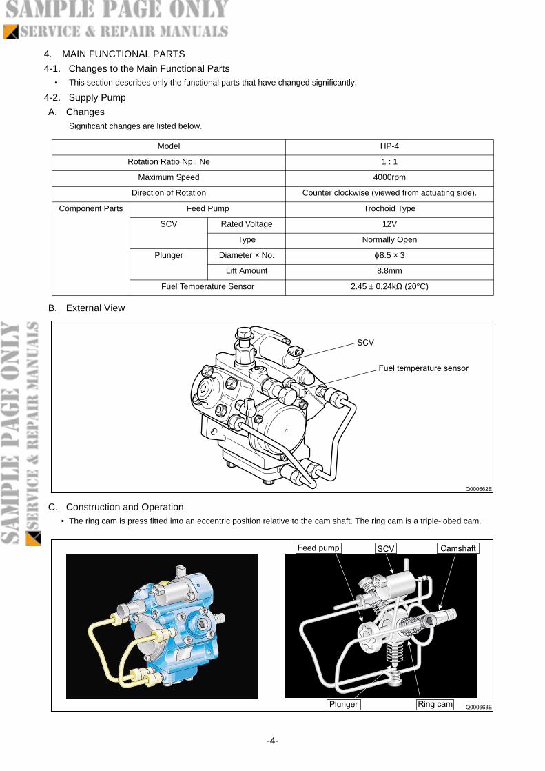
4-2. Supply Pump
A. ChangesSignificant changes are listed below.
B. External View
C. Construction and Operation• The ring cam is press fitted into an eccentric position relative to the cam shaft. The ring cam is a triple-lobed cam.
Model HP-4
Rotation Ratio Np : Ne 1 : 1
Maximum Speed 4000rpm
Direction of Rotation Counter clockwise (viewed from actuating side).
Component Parts Feed Pump Trochoid Type
SCV Rated Voltage 12V
Type Normally Open
Plunger Diameter × No. ϕ8.5 × 3
Lift Amount 8.8mm
Fuel Temperature Sensor 2.45 ± 0.24kΩ (20°C)
Q000662E
SCV
Fuel temperature sensor
Q000663E
SCV CamshaftFeed pump
Plunger Ring cam
-4-