
Service Manual Model HPS- · PDF fileProcedure to check up color TV electrical parameters ......
49
Service Manual Model HPS-2185FS Customer: Makro Code: 1.01.72505.59 _____________________________________ Approved Signature
Transcript of Service Manual Model HPS- · PDF fileProcedure to check up color TV electrical parameters ......

Service Manual
Model HPS-2185FS
Customer: Makro Code: 1.01.72505.59
_____________________________________ Approved Signature
HPS-2185FS
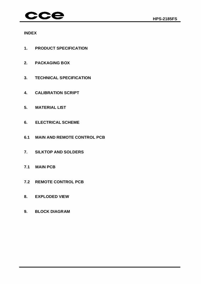
INDEX
1. PRODUCT SPECIFICATION
2. PACKAGING BOX
3. TECHNICAL SPECIFICATION
4. CALIBRATION SCRIPT
5. MATERIAL LIST
6. ELECTRICAL SCHEME
6.1 MAIN AND REMOTE CONTROL PCB
7. SILKTOP AND SOLDERS
7.1 MAIN PCB
7.2 REMOTE CONTROL PCB
8. EXPLODED VIEW
9. BLOCK DIAGRAM
HPS-2185FS
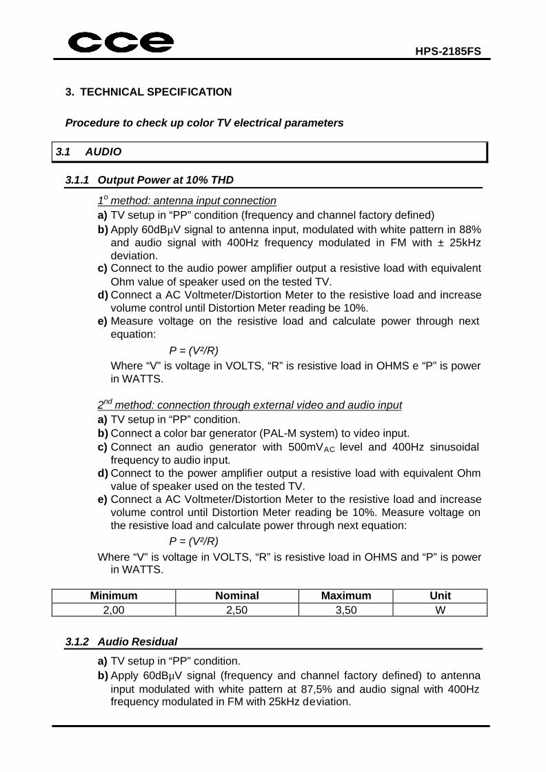
3. TECHNICAL SPECIFICATION
Procedure to check up color TV electrical parameters
3.1 AUDIO 3.1.1 Output Power at 10% THD
1o method: antenna input connection a) TV setup in “PP” condition (frequency and channel factory defined) b) Apply 60dBµV signal to antenna input, modulated with white pattern in 88%
and audio signal with 400Hz frequency modulated in FM with ± 25kHz deviation.
c) Connect to the audio power amplifier output a resistive load with equivalent Ohm value of speaker used on the tested TV.
d) Connect a AC Voltmeter/Distortion Meter to the resistive load and increase volume control until Distortion Meter reading be 10%.
e) Measure voltage on the resistive load and calculate power through next equation:
P = (V²/R) Where “V” is voltage in VOLTS, “R” is resistive load in OHMS e “P” is power
in WATTS. 2nd method: connection through external video and audio input a) TV setup in “PP” condition. b) Connect a color bar generator (PAL-M system) to video input. c) Connect an audio generator with 500mVAC level and 400Hz sinusoidal
frequency to audio input. d) Connect to the power amplifier output a resistive load with equivalent Ohm
value of speaker used on the tested TV. e) Connect a AC Voltmeter/Distortion Meter to the resistive load and increase
volume control until Distortion Meter reading be 10%. Measure voltage on the resistive load and calculate power through next equation:
P = (V²/R) Where “V” is voltage in VOLTS, “R” is resistive load in OHMS and “P” is power
in WATTS.
Minimum Nominal Maximum Unit 2,00 2,50 3,50 W
3.1.2 Audio Residual
a) TV setup in “PP” condition. b) Apply 60dBµV signal (frequency and channel factory defined) to antenna
input modulated with white pattern at 87,5% and audio signal with 400Hz frequency modulated in FM with 25kHz deviation.
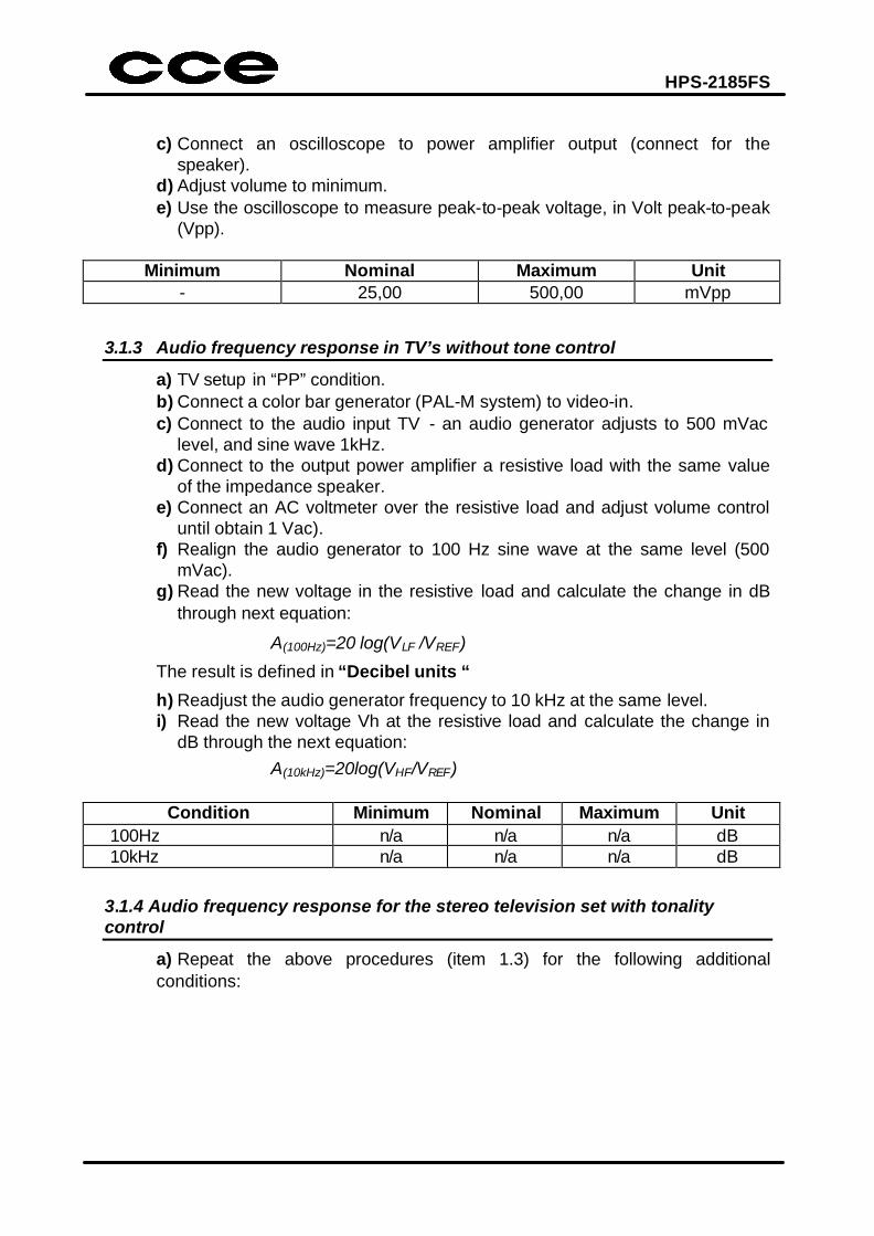
HPS-2185FS
c) Connect an oscilloscope to power amplifier output (connect for the speaker).
d) Adjust volume to minimum. e) Use the oscilloscope to measure peak-to-peak voltage, in Volt peak-to-peak
(Vpp).
Minimum Nominal Maximum Unit - 25,00 500,00 mVpp
3.1.3 Audio frequency response in TV’s without tone control
a) TV setup in “PP” condition. b) Connect a color bar generator (PAL-M system) to video-in. c) Connect to the audio input TV - an audio generator adjusts to 500 mVac
level, and sine wave 1kHz. d) Connect to the output power amplifier a resistive load with the same value
of the impedance speaker. e) Connect an AC voltmeter over the resistive load and adjust volume control
until obtain 1 Vac). f) Realign the audio generator to 100 Hz sine wave at the same level (500
mVac). g) Read the new voltage in the resistive load and calculate the change in dB
through next equation:
A(100Hz)=20 log(VLF /VREF)
The result is defined in “Decibel units “
h) Readjust the audio generator frequency to 10 kHz at the same level. i) Read the new voltage Vh at the resistive load and calculate the change in
dB through the next equation: A(10kHz)=20log(VHF/VREF)
Condition Minimum Nominal Maximum Unit 100Hz n/a n/a n/a dB 10kHz n/a n/a n/a dB
3.1.4 Audio frequency response for the stereo television set with tonality control
a) Repeat the above procedures (item 1.3) for the following additional conditions:
HPS-2185FS
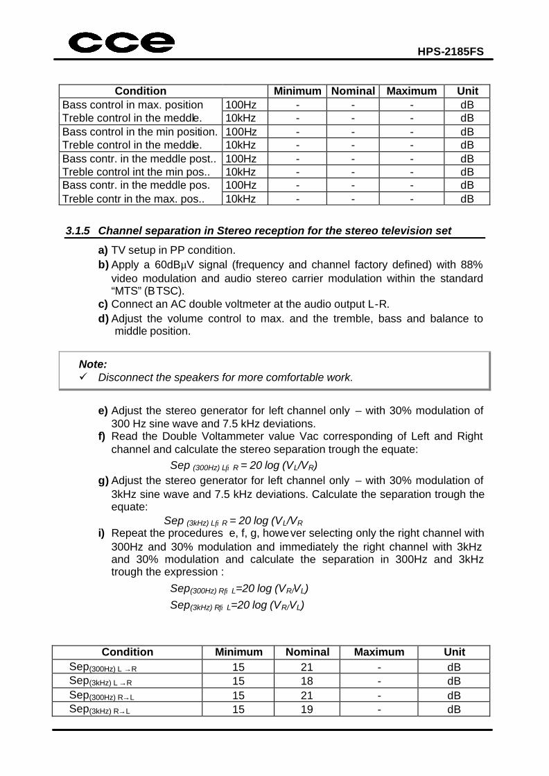
Condition Minimum Nominal Maximum Unit Bass control in max. position 100Hz - - - dB Treble control in the meddle. 10kHz - - - dB Bass control in the min position. 100Hz - - - dB Treble control in the meddle. 10kHz - - - dB Bass contr. in the meddle post.. 100Hz - - - dB Treble control int the min pos.. 10kHz - - - dB Bass contr. in the meddle pos. 100Hz - - - dB Treble contr in the max. pos.. 10kHz - - - dB
3.1.5 Channel separation in Stereo reception for the stereo television set
a) TV setup in PP condition. b) Apply a 60dBµV signal (frequency and channel factory defined) with 88%
video modulation and audio stereo carrier modulation within the standard “MTS” (BTSC).
c) Connect an AC double voltmeter at the audio output L-R. d) Adjust the volume control to max. and the tremble, bass and balance to
middle position.
Note: ü Disconnect the speakers for more comfortable work.
e) Adjust the stereo generator for left channel only – with 30% modulation of
300 Hz sine wave and 7.5 kHz deviations. f) Read the Double Voltammeter value Vac corresponding of Left and Right
channel and calculate the stereo separation trough the equate: Sep (300Hz) L→R = 20 log (VL/VR) g) Adjust the stereo generator for left channel only – with 30% modulation of
3kHz sine wave and 7.5 kHz deviations. Calculate the separation trough the equate:
Sep (3kHz) L→R = 20 log (VL/VR i) Repeat the procedures e, f, g, however selecting only the right channel with
300Hz and 30% modulation and immediately the right channel with 3kHz and 30% modulation and calculate the separation in 300Hz and 3kHz trough the expression :
Sep(300Hz) R→L=20 log (VR/VL) Sep(3kHz) R→L=20 log (VR/VL)
Condition Minimum Nominal Maximum Unit Sep(300Hz) L →R 15 21 - dB Sep(3kHz) L →R 15 18 - dB Sep(300Hz) R→L 15 21 - dB Sep(3kHz) R→L 15 19 - dB
HPS-2185FS
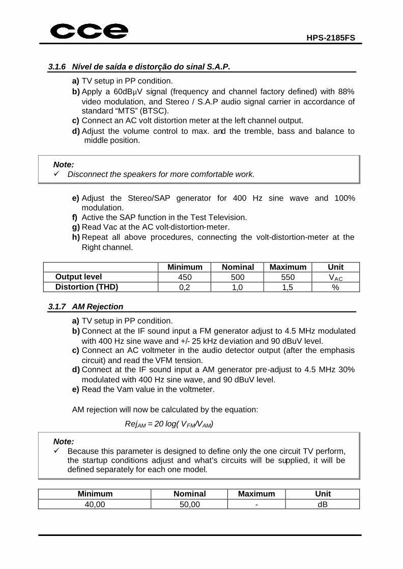
3.1.6 Nível de saída e distorção do sinal S.A.P.
a) TV setup in PP condition. b) Apply a 60dBµV signal (frequency and channel factory defined) with 88%
video modulation, and Stereo / S.A.P audio signal carrier in accordance of standard “MTS” (BTSC).
c) Connect an AC volt distortion meter at the left channel output. d) Adjust the volume control to max. and the tremble, bass and balance to
middle position.
Note: ü Disconnect the speakers for more comfortable work.
e) Adjust the Stereo/SAP generator for 400 Hz sine wave and 100%
modulation. f) Active the SAP function in the Test Television. g) Read Vac at the AC volt-distortion-meter. h) Repeat all above procedures, connecting the volt-distortion-meter at the
Right channel.
Minimum Nominal Maximum Unit Output level 450 500 550 VAC Distortion (THD) 0,2 1,0 1,5 %
3.1.7 AM Rejection
a) TV setup in PP condition. b) Connect at the IF sound input a FM generator adjust to 4.5 MHz modulated
with 400 Hz sine wave and +/- 25 kHz deviation and 90 dBuV level. c) Connect an AC voltmeter in the audio detector output (after the emphasis
circuit) and read the VFM tension. d) Connect at the IF sound input a AM generator pre-adjust to 4.5 MHz 30%
modulated with 400 Hz sine wave, and 90 dBuV level. e) Read the Vam value in the voltmeter. AM rejection will now be calculated by the equation:
RejAM = 20 log( VFM/VAM)
Note: ü Because this parameter is designed to define only the one circuit TV perform,
the startup conditions adjust and what’s circuits will be supplied, it will be defined separately for each one model.
Minimum Nominal Maximum Unit
40,00 50,00 - dB
HPS-2185FS
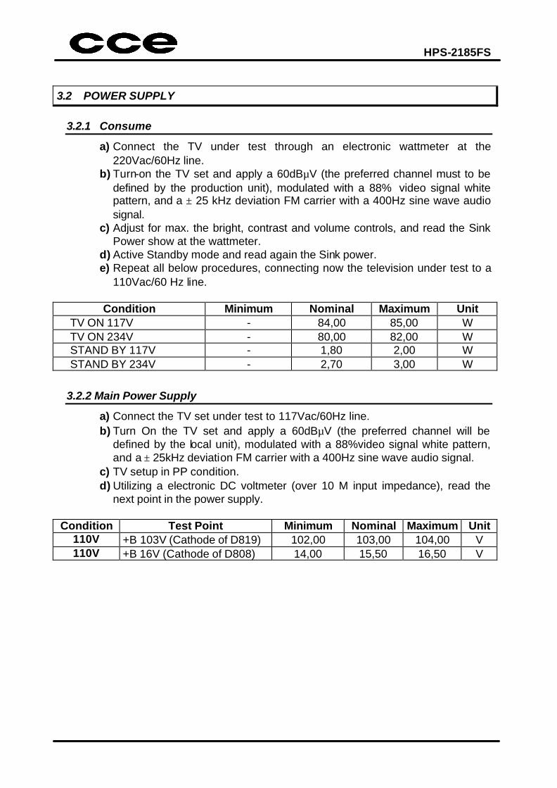
3.2 POWER SUPPLY
3.2.1 Consume
a) Connect the TV under test through an electronic wattmeter at the 220Vac/60Hz line.
b) Turn-on the TV set and apply a 60dBµV (the preferred channel must to be defined by the production unit), modulated with a 88% video signal white pattern, and a ± 25 kHz deviation FM carrier with a 400Hz sine wave audio signal.
c) Adjust for max. the bright, contrast and volume controls, and read the Sink Power show at the wattmeter.
d) Active Standby mode and read again the Sink power. e) Repeat all below procedures, connecting now the television under test to a
110Vac/60 Hz line.
Condition Minimum Nominal Maximum Unit TV ON 117V - 84,00 85,00 W TV ON 234V - 80,00 82,00 W STAND BY 117V - 1,80 2,00 W STAND BY 234V - 2,70 3,00 W
3.2.2 Main Power Supply
a) Connect the TV set under test to 117Vac/60Hz line. b) Turn On the TV set and apply a 60dBµV (the preferred channel will be
defined by the local unit), modulated with a 88%video signal white pattern, and a ± 25kHz deviation FM carrier with a 400Hz sine wave audio signal.
c) TV setup in PP condition. d) Utilizing a electronic DC voltmeter (over 10 M input impedance), read the
next point in the power supply.
Condition Test Point Minimum Nominal Maximum Unit 110V +B 103V (Cathode of D819) 102,00 103,00 104,00 V 110V +B 16V (Cathode of D808) 14,00 15,50 16,50 V
HPS-2185FS
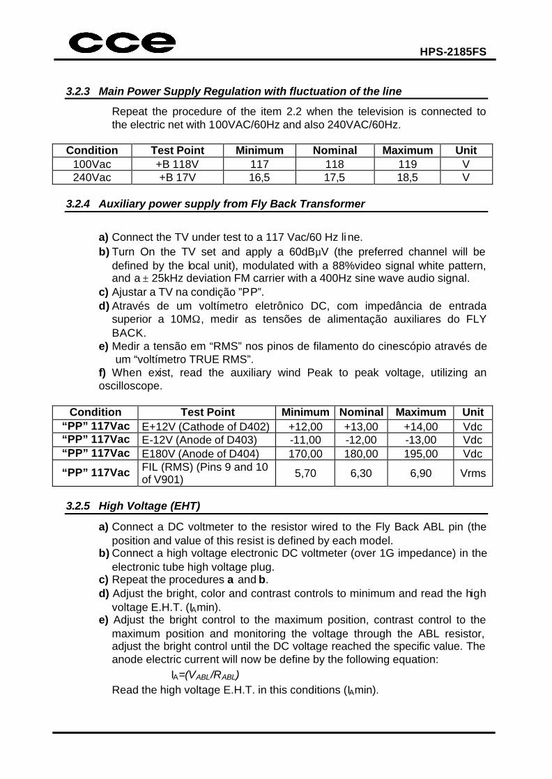
3.2.3 Main Power Supply Regulation with fluctuation of the line
Repeat the procedure of the item 2.2 when the television is connected to the electric net with 100VAC/60Hz and also 240VAC/60Hz.
Condition Test Point Minimum Nominal Maximum Unit
100Vac +B 118V 117 118 119 V 240Vac +B 17V 16,5 17,5 18,5 V
3.2.4 Auxiliary power supply from Fly Back Transformer
a) Connect the TV under test to a 117 Vac/60 Hz line. b) Turn On the TV set and apply a 60dBµV (the preferred channel will be
defined by the local unit), modulated with a 88%video signal white pattern, and a ± 25kHz deviation FM carrier with a 400Hz sine wave audio signal.
c) Ajustar a TV na condição ”PP”. d) Através de um voltímetro eletrônico DC, com impedância de entrada
superior a 10MΩ, medir as tensões de alimentação auxiliares do FLY BACK.
e) Medir a tensão em “RMS” nos pinos de filamento do cinescópio através de um “voltímetro TRUE RMS”.
f) When exist, read the auxiliary wind Peak to peak voltage, utilizing an oscilloscope.
Condition Test Point Minimum Nominal Maximum Unit
“PP” 117Vac E+12V (Cathode of D402) +12,00 +13,00 +14,00 Vdc “PP” 117Vac E-12V (Anode of D403) -11,00 -12,00 -13,00 Vdc “PP” 117Vac E180V (Anode of D404) 170,00 180,00 195,00 Vdc
“PP” 117Vac FIL (RMS) (Pins 9 and 10 of V901) 5,70 6,30 6,90 Vrms
3.2.5 High Voltage (EHT)
a) Connect a DC voltmeter to the resistor wired to the Fly Back ABL pin (the position and value of this resist is defined by each model.
b) Connect a high voltage electronic DC voltmeter (over 1G impedance) in the electronic tube high voltage plug.
c) Repeat the procedures a and b. d) Adjust the bright, color and contrast controls to minimum and read the high
voltage E.H.T. (IAmin). e) Adjust the bright control to the maximum position, contrast control to the
maximum position and monitoring the voltage through the ABL resistor, adjust the bright control until the DC voltage reached the specific value. The anode electric current will now be define by the following equation:
IA=(VABL/RABL) Read the high voltage E.H.T. in this conditions (IAmin).
HPS-2185FS
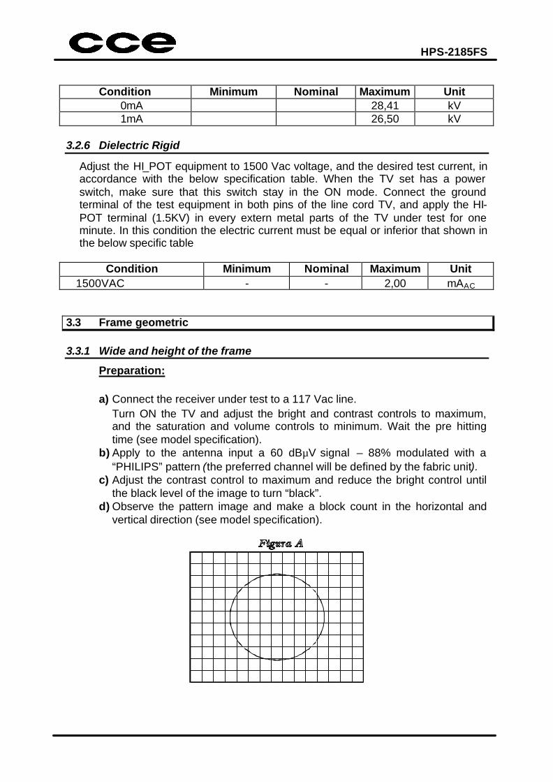
Condition Minimum Nominal Maximum Unit 0mA 28,41 kV 1mA 26,50 kV
3.2.6 Dielectric Rigid
Adjust the HI_POT equipment to 1500 Vac voltage, and the desired test current, in accordance with the below specification table. When the TV set has a power switch, make sure that this switch stay in the ON mode. Connect the ground terminal of the test equipment in both pins of the line cord TV, and apply the HI-POT terminal (1.5KV) in every extern metal parts of the TV under test for one minute. In this condition the electric current must be equal or inferior that shown in the below specific table
Condition Minimum Nominal Maximum Unit
1500VAC - - 2,00 mAAC 3.3 Frame geometric 3.3.1 Wide and height of the frame
Preparation: a) Connect the receiver under test to a 117 Vac line. Turn ON the TV and adjust the bright and contrast controls to maximum,
and the saturation and volume controls to minimum. Wait the pre hitting time (see model specification).
b) Apply to the antenna input a 60 dBµV signal – 88% modulated with a “PHILIPS” pattern (the preferred channel will be defined by the fabric unit).
c) Adjust the contrast control to maximum and reduce the bright control until the black level of the image to turn “black”.
d) Observe the pattern image and make a block count in the horizontal and vertical direction (see model specification).
HPS-2185FS
Minimum Nominal Maximum Unit Height (PAL-N) n/a n/a n/a Blocks Wide (PAL-N) n/a n/a n/a Blocks Height (PAL-M) n/a n/a n/a Blocks Wide (PAL-M) n/a n/a n/a Blocks
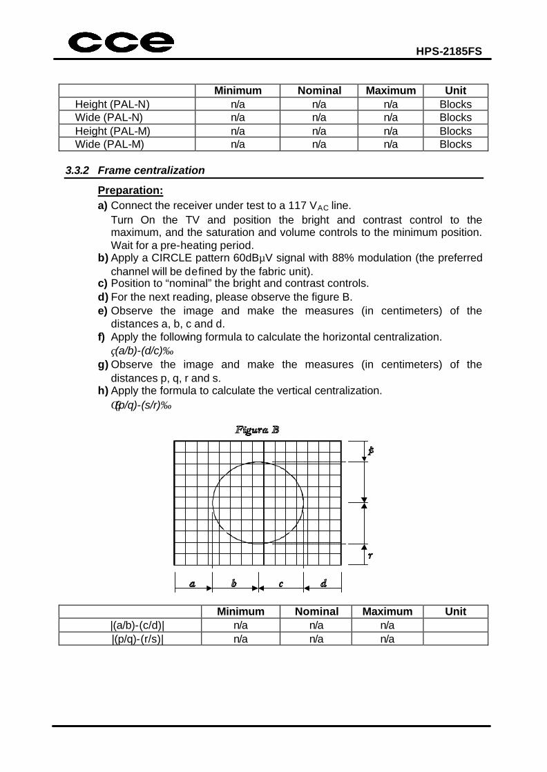
3.3.2 Frame centralization
Preparation: a) Connect the receiver under test to a 117 VAC line.
Turn On the TV and position the bright and contrast control to the maximum, and the saturation and volume controls to the minimum position. Wait for a pre-heating period.
b) Apply a CIRCLE pattern 60dBµV signal with 88% modulation (the preferred channel will be defined by the fabric unit).
c) Position to “nominal” the bright and contrast controls. d) For the next reading, please observe the figure B. e) Observe the image and make the measures (in centimeters) of the
distances a, b, c and d. f) Apply the following formula to calculate the horizontal centralization. (a/b)-(d/c) g) Observe the image and make the measures (in centimeters) of the
distances p, q, r and s. h) Apply the formula to calculate the vertical centralization. (p/q)-(s/r)
Minimum Nominal Maximum Unit |(a/b)-(c/d)| n/a n/a n/a |(p/q)-(r/s)| n/a n/a n/a
HPS-2185FS
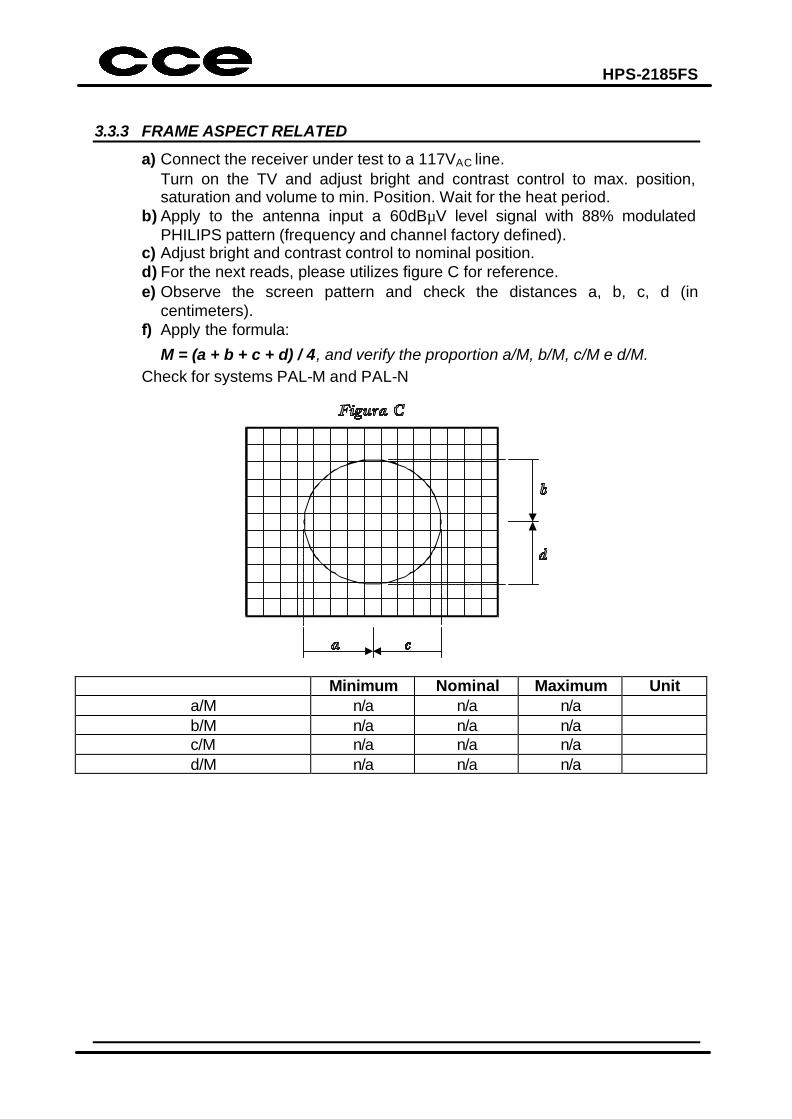
3.3.3 FRAME ASPECT RELATED
a) Connect the receiver under test to a 117VAC line. Turn on the TV and adjust bright and contrast control to max. position,
saturation and volume to min. Position. Wait for the heat period. b) Apply to the antenna input a 60dBµV level signal with 88% modulated
PHILIPS pattern (frequency and channel factory defined). c) Adjust bright and contrast control to nominal position. d) For the next reads, please utilizes figure C for reference. e) Observe the screen pattern and check the distances a, b, c, d (in
centimeters). f) Apply the formula:
M = (a + b + c + d) / 4, and verify the proportion a/M, b/M, c/M e d/M. Check for systems PAL-M and PAL-N
Minimum Nominal Maximum Unit a/M n/a n/a n/a b/M n/a n/a n/a c/M n/a n/a n/a d/M n/a n/a n/a
HPS-2185FS
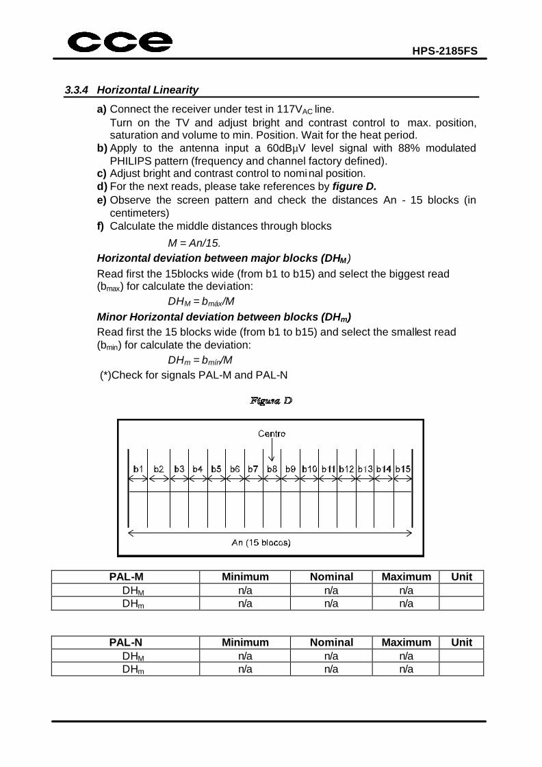
3.3.4 Horizontal Linearity
a) Connect the receiver under test in 117VAC line. Turn on the TV and adjust bright and contrast control to max. position,
saturation and volume to min. Position. Wait for the heat period. b) Apply to the antenna input a 60dBµV level signal with 88% modulated
PHILIPS pattern (frequency and channel factory defined). c) Adjust bright and contrast control to nominal position. d) For the next reads, please take references by figure D. e) Observe the screen pattern and check the distances An - 15 blocks (in
centimeters) f) Calculate the middle distances through blocks
M = An/15. Horizontal deviation between major blocks (DHM )
Read first the 15blocks wide (from b1 to b15) and select the biggest read (bmax) for calculate the deviation:
DHM = bmáx/M Minor Horizontal deviation between blocks (DHm)
Read first the 15 blocks wide (from b1 to b15) and select the smallest read (bmin) for calculate the deviation:
DHm = bmín/M (*)Check for signals PAL-M and PAL-N
PAL-M Minimum Nominal Maximum Unit DHM n/a n/a n/a DHm n/a n/a n/a
PAL-N Minimum Nominal Maximum Unit DHM n/a n/a n/a DHm n/a n/a n/a
HPS-2185FS
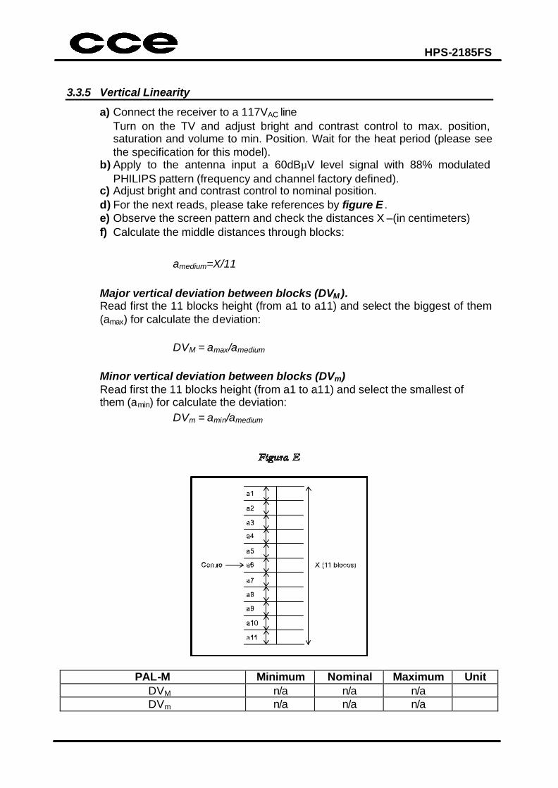
3.3.5 Vertical Linearity
a) Connect the receiver to a 117VAC line Turn on the TV and adjust bright and contrast control to max. position,
saturation and volume to min. Position. Wait for the heat period (please see the specification for this model).
b) Apply to the antenna input a 60dBµV level signal with 88% modulated PHILIPS pattern (frequency and channel factory defined).
c) Adjust bright and contrast control to nominal position. d) For the next reads, please take references by figure E . e) Observe the screen pattern and check the distances X –(in centimeters) f) Calculate the middle distances through blocks: amedium=X/11 Major vertical deviation between blocks (DVM ). Read first the 11 blocks height (from a1 to a11) and select the biggest of them
(amax) for calculate the deviation:
DVM = amax/amedium
Minor vertical deviation between blocks (DVm)
Read first the 11 blocks height (from a1 to a11) and select the smallest of them (amin) for calculate the deviation:
DVm = amin/amedium
PAL-M Minimum Nominal Maximum Unit DVM n/a n/a n/a DVm n/a n/a n/a
HPS-2185FS
PAL-N Minimum Nominal Maximum Unit DVM n/a n/a n/a DVm n/a n/a n/a
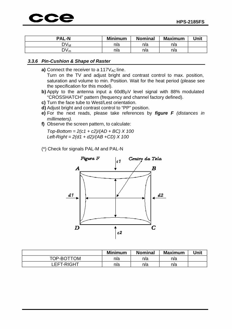
3.3.6 Pin-Cushion & Shape of Raster
a) Connect the receiver to a 117VAC line. Turn on the TV and adjust bright and contrast control to max. position,
saturation and volume to min. Position. Wait for the heat period (please see the specification for this model).
b) Apply to the antenna input a 60dBµV level signal with 88% modulated “CROSSHATCH” pattern (frequency and channel factory defined).
c) Turn the face tube to West/Lest orientation. d) Adjust bright and contrast control to “PP” position. e) For the next reads, please take references by figure F (distances in
millimeters). f) Observe the screen pattern, to calculate:
Top-Bottom = 2(c1 + c2)/(AD + BC) X 100 Left-Right = 2(d1 + d2)/(AB +CD) X 100
(*) Check for signals PAL-M and PAL-N
Minimum Nominal Maximum Unit TOP-BOTTOM n/a n/a n/a LEFT-RIGHT n/a n/a n/a
HPS-2185FS
3.4 Purity
a) Connect the receiver to a 117VAC line Turn on the TV and adjust bright to nominal position and contrast control to
min. position, saturation and volume to min. position. b) Apply to the antenna input a 60dBµV level signal with 88% modulated
“WHITE” pattern (frequency and channel factory defined). c) Wait for pre-heating period (30 minutes). d) Turn the face tube to West/Lest orientation. e) Degauss the device appropriated. f) Increment the contrast controls to max. position, and wait for 3 minutes g) At a distance of 5 times the height of the screen, observe that no color dirty
may appear. h) Repeat this procedures now utilizing a red pattern.
Note: ü If the receiver is moved during the test procedure, always degauss again the
device
3.5 Convergence a) Connect the receiver to a 117VAC line. Turn on the TV and adjust bright and contrast control to max. position,
saturation and volume to min. position. Wait for pre-heating period (please see specification for each model).
b) Apply to the antenna input a 60dBµV level signal with 88% modulated “CROSSHATCH” pattern (frequency and channel factory defined).
c) Turn the face tube to West/Lest orientation. d) Degauss the device properly. e) Adjust bright and contrast control to minimum position.
f) For the next reads, please take references by figure G (distances in millimeters).
g) Observing the picture in the screen and with the aid of Convergence Gauge, measure in the positions indicated by the figure G.
a) Distance between centers of vertical lines (X); b) Distance between centers of horizontal lines (Y) to: - R/G (red / green) - R/B (red / blue) - B/G (blue / green) (See specification for each model)) (*) Apply for signals PAL-M and PAL-N
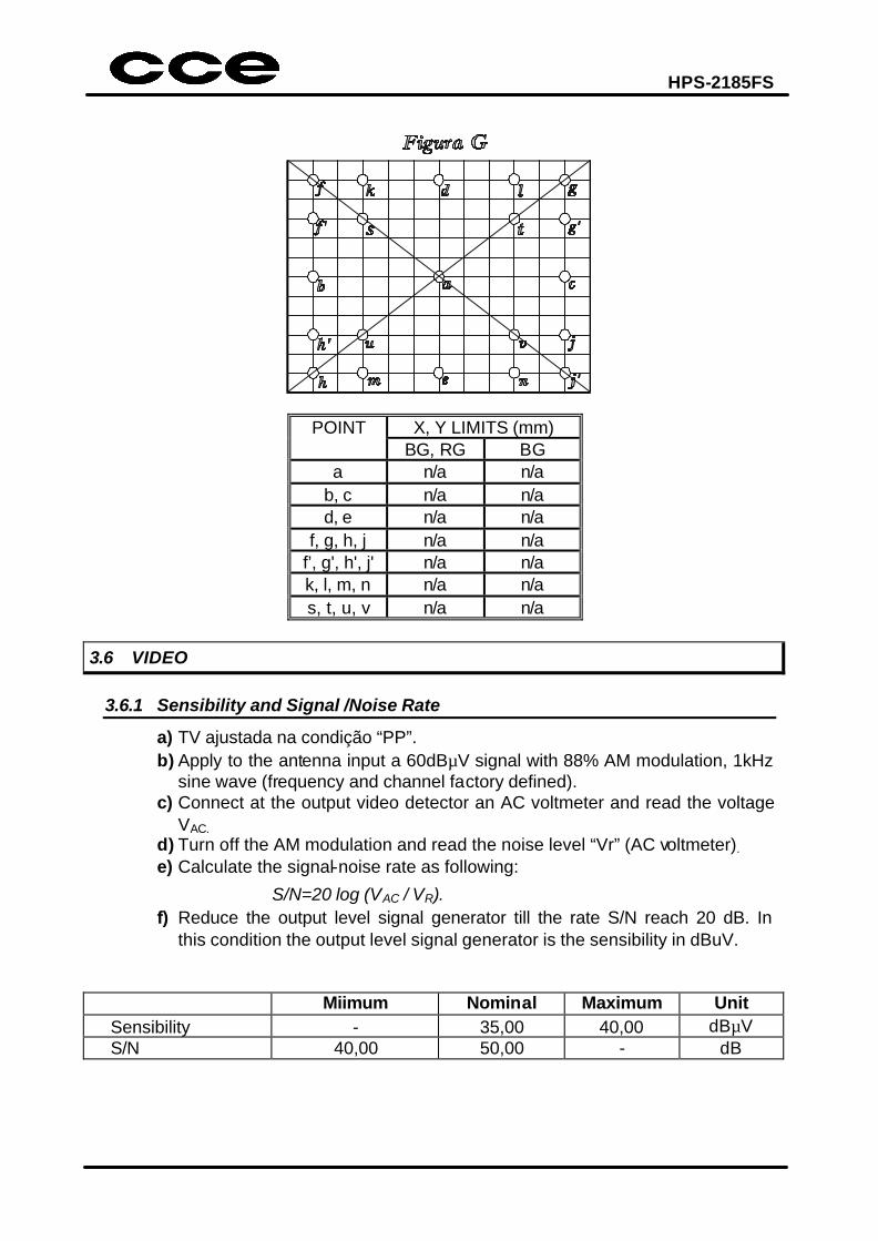
HPS-2185FS
POINT X, Y LIMITS (mm) BG, RG BG
a n/a n/a b, c n/a n/a d, e n/a n/a
f, g, h, j n/a n/a f’, g', h', j' n/a n/a k, l, m, n n/a n/a s, t, u, v n/a n/a
3.6 VIDEO
3.6.1 Sensibility and Signal /Noise Rate
a) TV ajustada na condição “PP”. b) Apply to the antenna input a 60dBµV signal with 88% AM modulation, 1kHz
sine wave (frequency and channel factory defined). c) Connect at the output video detector an AC voltmeter and read the voltage
VAC. d) Turn off the AM modulation and read the noise level “Vr” (AC voltmeter).
e) Calculate the signal-noise rate as following:
S/N=20 log (VAC / VR). f) Reduce the output level signal generator till the rate S/N reach 20 dB. In
this condition the output level signal generator is the sensibility in dBuV.
Miimum Nominal Maximum Unit Sensibility - 35,00 40,00 dBµV S/N 40,00 50,00 - dB
HPS-2185FS
3.6.2 Chrome sensibility
a) Adjust the TV to a “PP” condition. b) Apply to the antenna input a 60dBµV signal with 88% AM modulation with
PAL-M color pattern (frequency and channel factory defined), and FM sine wave 400Hz audio modulation +-25 kHz deviation.
c) Observe the TV screen under test and reduce the output generator level until the color pattern be visible. At this condition the output generator level represents the sensibility of chrome in dBµV.
Note: If the TV under test is two or three-system mode, repeat this procedures for the PAL-N and NTSC-M signal system.
Condition Minimum Nominal Maximum Unit
PAL-M - 300,00 400,00 dBµV PAL-N - 300,00 400,00 dBµV NTSC-M - 300,00 400,00 dBµV
3.6.3 AGC circuit
a) Apply to the antenna input a 60dBµV signal with 88% AM modulation with “WHITE” pattern (frequency and channel factory defined), and FM sine wave 400 Hz audio modulation +-25 kHz deviation.
b) Adjust the TV to “PP” condition. c) Read the DC voltage at the tuner AGC terminal. Utilize a DC electronic
voltmeter with minimum 10 MΩ impedance.
Condition Minimum Nominal Maximum Unit Vcc = 5V -10% (1/2)Vcc +10% VDC
3.6.4 AFT circuit
a) Apply to the antenna input a 60dBµV signal with 88% AM modulation with PAL-M COLOR BAR pattern (frequency and channel factory defined), and FM sine wave 400 Hz audio modulation +-25 kHz deviation.
b) Connect a oscilloscope in the output video detector and read the peak to peak burst level signal “Vb”.
c) Increment the generator frequency by 500 kHz and read the new value peak to peak burst signal “Vh” and calculate the percentage as following:
E= VH/VBx100% d) Decrement the generator frequency by 500 kHz and repeat the
procedure(c) reading the peak-to-peak burst signal VL and calculate the percentage as following:
E= VL/VBx100%
HPS-2185FS
Minimum Nominal Maximum Unit EH 0,80 1,00 +1,20 % EL 0,80 1,00 +1,20 %
4. CALIBRATION SCRIPT
Note: This guide is only an orientation and, for some items, may be adapted by Factory Engineering to best conform to the productive process.
INTRODUCTION
Note: ü It is necessary to pre-heat the TV during 15 minutes, before its
calibration.
1) Important recommendations 2) Definitions of the terms 3) Geometry of the Image 4) White Balance 5) Screen adjustment 6) AGC adjustment How to select the FACTORY MODE a) Short to ground pin 78 of IC101 (momentarily) or press the service key in
the service remote control (see the description of service remote control). b) Select the adjustment options pressing the key CHÙ or CHÚ of the remote
control, of the television front panel or use the service remote control (see the description of service remote control).
Note: All the adjustment options can be selected directly by the remote control numeric keys.
c) Adjust the selected option pressing the key VOLØ or ×VOL of the remote
control, of the television front panel or use the service remote control(see the description of service remote control).
c1) VOLØ - increases registers (MAX.). c2)×VOL - decreases registers (MIN.). d) To exit the FACTORY MODE, use the key OSD/OUT of the remote control.

HPS-2185FS
4.1 Important recommendations 4.1.1 Before beginning the adjustments, the TV set should be a pre-heated during at
least 15 minutes.
4.1.2 The positioning of the TV set should be the magnetic parameters of South America that it is -120 vertical mG. In the practice, this is gotten with a relative precision, positioning the TV set with the face (screen) of the CRT pointing to the geographical East.
Note: These cares should also be taken when CQ will analyze the TV set.
HPS-2185FS
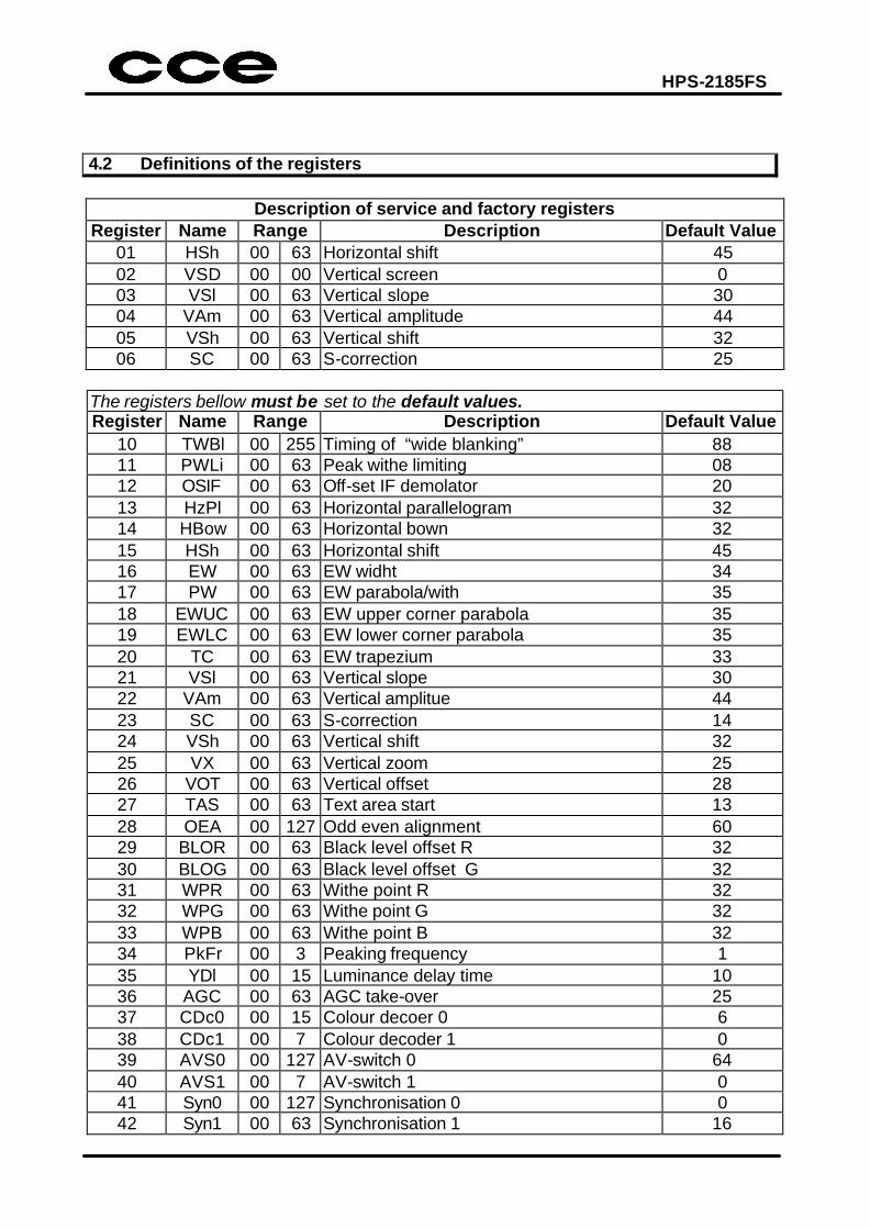
4.2 Definitions of the registers
Description of service and factory registers
Register Name Range Description Default Value 01 HSh 00 63 Horizontal shift 45 02 VSD 00 00 Vertical screen 0 03 VSl 00 63 Vertical slope 30 04 VAm 00 63 Vertical amplitude 44 05 VSh 00 63 Vertical shift 32 06 SC 00 63 S-correction 25
The registers bellow must be set to the default values. Register Name Range Description Default Value
10 TWBl 00 255 Timing of “wide blanking” 88 11 PWLi 00 63 Peak withe limiting 08 12 OSIF 00 63 Off-set IF demolator 20 13 HzPl 00 63 Horizontal parallelogram 32 14 HBow 00 63 Horizontal bown 32 15 HSh 00 63 Horizontal shift 45 16 EW 00 63 EW widht 34 17 PW 00 63 EW parabola/with 35 18 EWUC 00 63 EW upper corner parabola 35 19 EWLC 00 63 EW lower corner parabola 35 20 TC 00 63 EW trapezium 33 21 VSl 00 63 Vertical slope 30 22 VAm 00 63 Vertical amplitue 44 23 SC 00 63 S-correction 14 24 VSh 00 63 Vertical shift 32 25 VX 00 63 Vertical zoom 25 26 VOT 00 63 Vertical offset 28 27 TAS 00 63 Text area start 13 28 OEA 00 127 Odd even alignment 60 29 BLOR 00 63 Black level offset R 32 30 BLOG 00 63 Black level offset G 32 31 WPR 00 63 Withe point R 32 32 WPG 00 63 Withe point G 32 33 WPB 00 63 Withe point B 32 34 PkFr 00 3 Peaking frequency 1 35 YDl 00 15 Luminance delay time 10 36 AGC 00 63 AGC take-over 25 37 CDc0 00 15 Colour decoer 0 6 38 CDc1 00 7 Colour decoder 1 0 39 AVS0 00 127 AV-switch 0 64 40 AVS1 00 7 AV-switch 1 0 41 Syn0 00 127 Synchronisation 0 0 42 Syn1 00 63 Synchronisation 1 16
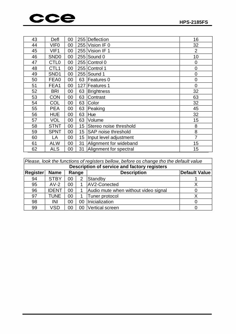
HPS-2185FS
43 Defl 00 255 Deflection 16 44 VIF0 00 255 Vision IF 0 32 45 VIF1 00 255 Vision IF 1 2 46 SND0 00 255 Sound 0 10 47 CTL0 00 255 Control 0 0 48 CTL1 00 255 Control 1 0 49 SND1 00 255 Sound 1 0 50 FEA0 00 63 Features 0 0 51 FEA1 00 127 Features 1 0 52 BRI 00 63 Brightness 32 53 CON 00 63 Contrast 63 54 COL 00 63 Color 32 55 PEA 00 63 Peaking 45 56 HUE 00 63 Hue 32 57 VOL 00 63 Volume 15 58 STNT 00 15 Stereo noise threshold 8 59 SPNT 00 15 SAP noise threshold 8 60 LA 00 15 Input level adjustment 7 61 ALW 00 31 Alignment for wideband 15 62 ALS 00 31 Alignment for spectral 15
Please, look the functions of registers bellow, before os change tho the default value
Description of service and factory registers Register Name Range Description Default Value
94 STBY 00 2 Standby 1 95 AV-2 00 1 AV2-Conected X 96 IDENT 00 1 Audio mute when without video signal 0 97 TUNE 00 1 Tuner protocol X 98 INI 00 00 Inicialization 0 99 VSD 00 00 Vertical screen 0
HPS-2185FS
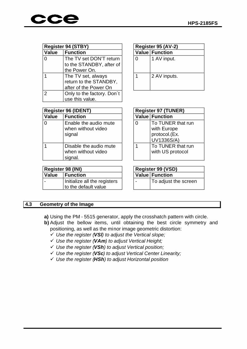
Register 94 (STBY) Register 95 (AV-2) Value Function Value Function 0 The TV set DON’T return
to the STANDBY, after of the Power On.
0 1 AV input.
1 The TV set, always return to the STANDBY, after of the Power On
1 2 AV inputs.
2 Only to the factory. Don´t use this value.
Register 96 (IDENT) Register 97 (TUNER) Value Function Value Function 0 Enable the audio mute
when without video signal
0 To TUNER that run with Europe protocol.(Ex. UV1336S/A)
1 Disable the audio mute when without video signal.
1 To TUNER that run with US protocol
Register 98 (INI) Register 99 (VSD) Value Function Value Function - Initialize all the registers
to the default value - To adjust the screen
4.3 Geometry of the Image
a) Using the PM - 5515 generator, apply the crosshatch pattern with circle. b) Adjust the bellow items, until obtaining the best circle symmetry and
positioning, as well as the minor image geometric distortion: ü Use the register (VSl) to adjust the Vertical slope; ü Use the register (VAm) to adjust Vertical Height; ü Use the register (VSh) to adjust Vertical position; ü Use the register (VSc) to adjust Vertical Center Linearity; ü Use the register (HSh) to adjust Horizontal position
HPS-2185FS
4.4 White balance
Note: ü The cut point doesn’t need adjustment, because it’s automatically made by
the IC101. ü The white adjustment is already pre-adjusted and incised in the IC101
and, thus, its adjustment is not necessary.
Otherwise, if it is necessary to change the temperature of the white pattern, proceed in the following way:
a) Enter in the service mode. b) Select via CHÙ or CHÚ the WPR (29), WPG (30) and WPB (31) functions. c) Increase or decrease the function via VOLØ or via ×VOL respectively.
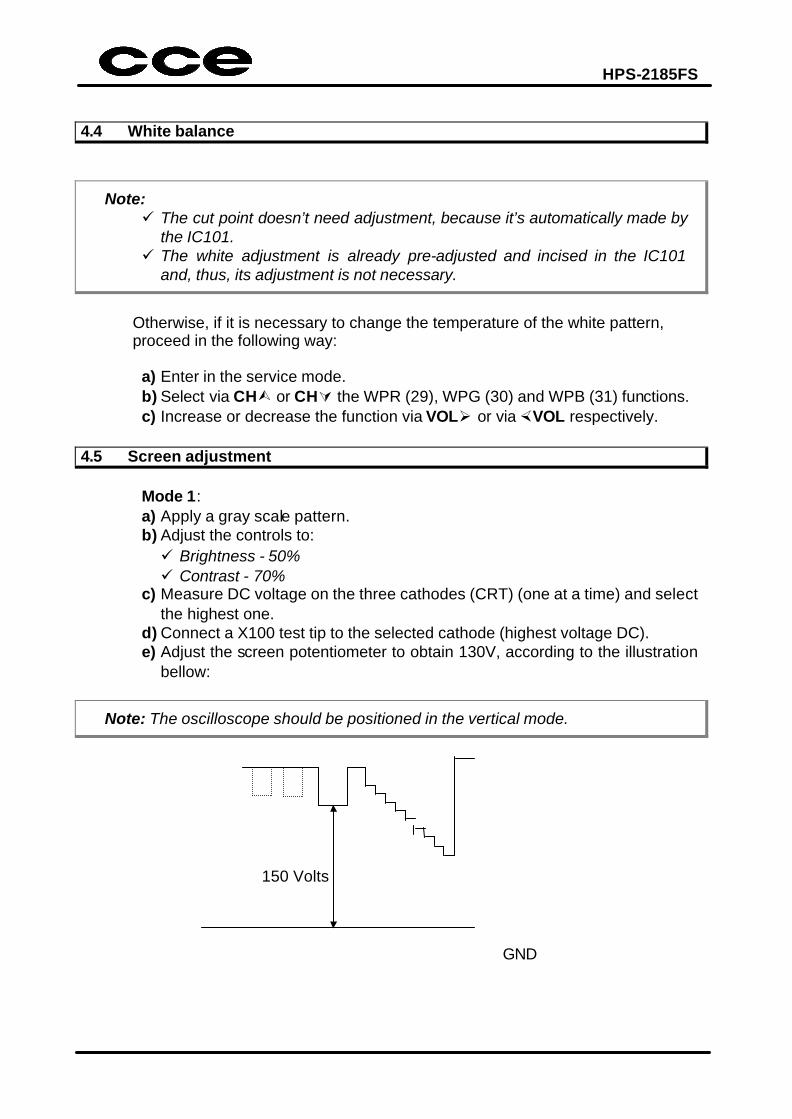
4.5 Screen adjustment
Mode 1: a) Apply a gray scale pattern. b) Adjust the controls to: ü Brightness - 50% ü Contrast - 70%
c) Measure DC voltage on the three cathodes (CRT) (one at a time) and select the highest one.
d) Connect a X100 test tip to the selected cathode (highest voltage DC). e) Adjust the screen potentiometer to obtain 130V, according to the illustration
bellow:
Note: The oscilloscope should be positioned in the vertical mode.
150 Volts GND
HPS-2185FS
Mode 2: a) Select the register 99 (VSD). b) Press VOLØ or ×VOL to select and adjust the screen control localized on
the FBT, until the horizontal line be slightly visible on the screen center.
4.6 AGC adjustment
Mode 1: ü Apply a PHILIPS pattern with 60dBµV of intensity and adjust the delay
until obtain 3.5V in AGC pin of tuner.
HPS-2185FS
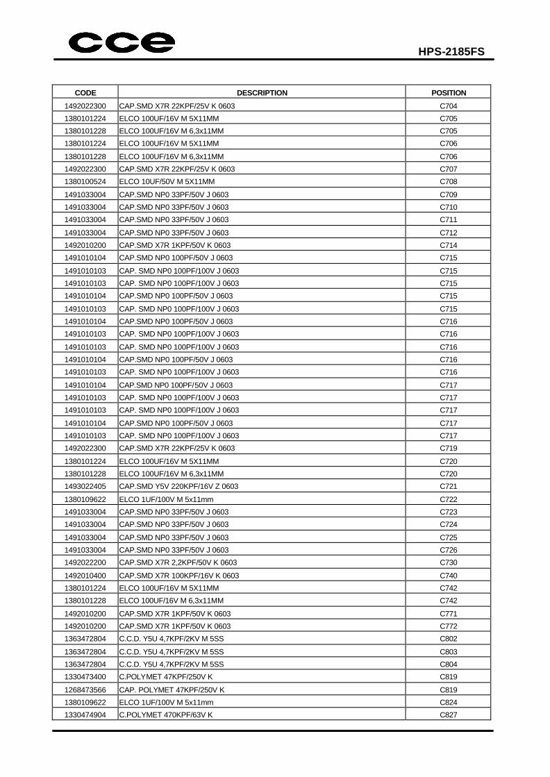
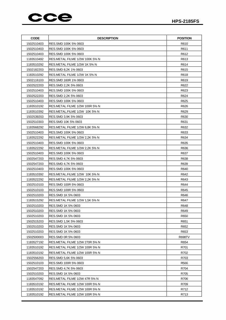
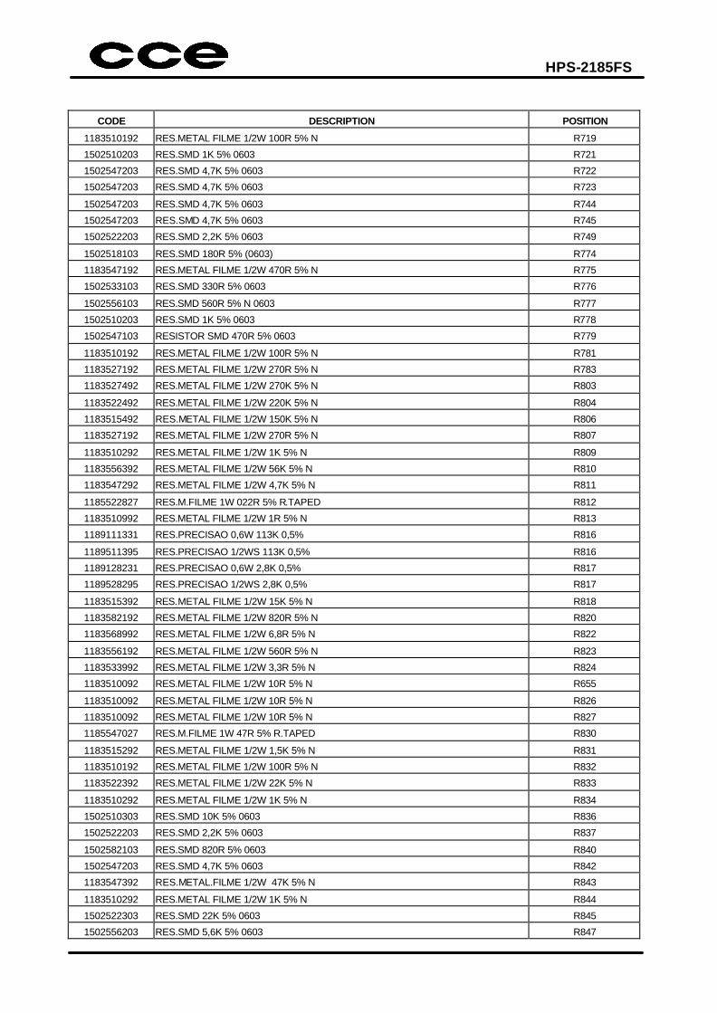
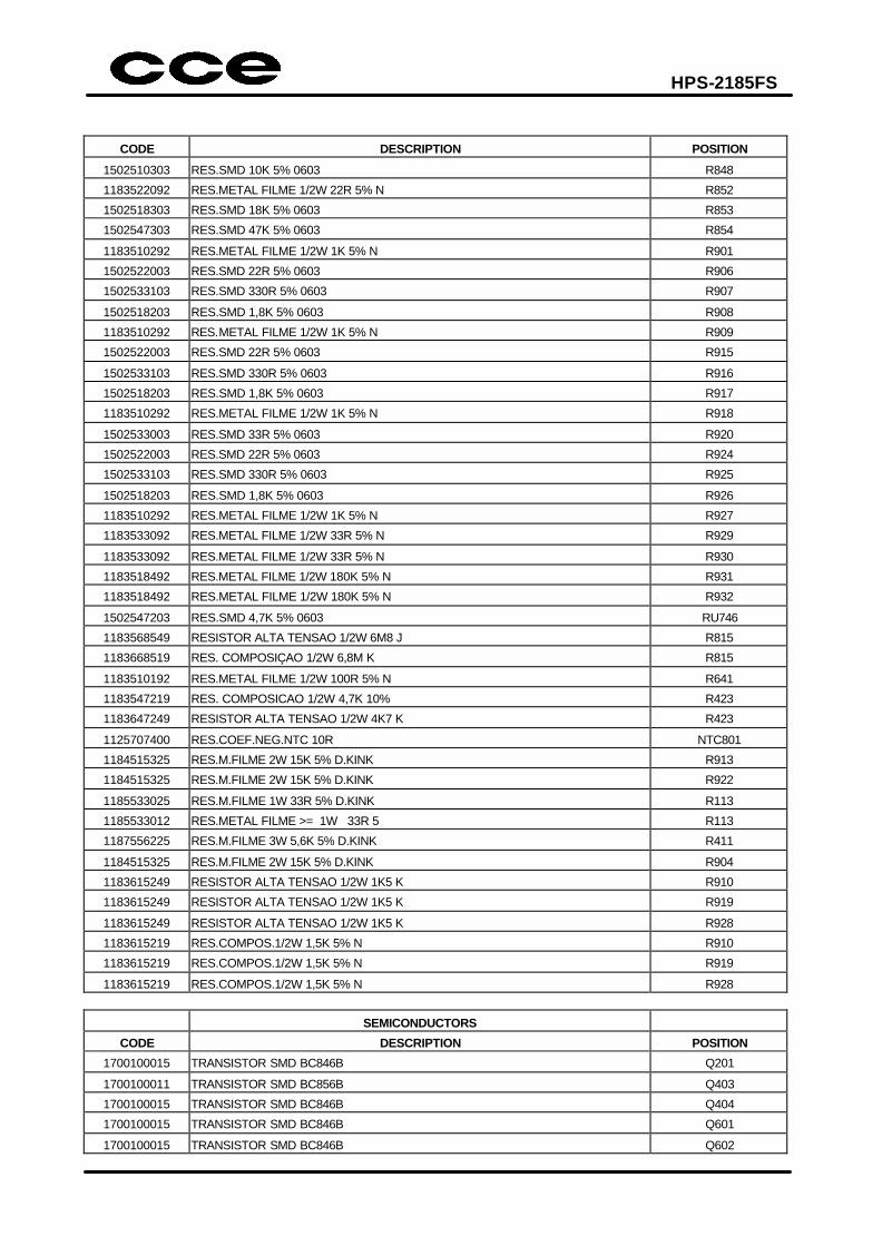
5. MATERIAL LIST
MAIN PCB
CAPACITORS
CODE DESCRIPTION POSITION
1380220528 ELCO 22UF/50V M 5X11MM C101
1492010400 CAP.SMD X7R 100KPF/16V K 0603 C102
1492022300 CAP.SMD X7R 22KPF/25V K 0603 C560
1492022300 CAP.SMD X7R 22KPF/25V K 0603 C561
1492022300 CAP.SMD X7R 22KPF/25V K 0603 C562
1380100524 ELCO 10UF/50V M 5X11MM C104
1492010300 CAP.SMD X7R 10KPF/50V K 0603 C105
1492010300 CAP.SMD X7R 10KPF/50V K 0603 C106
1380471225 ELCO 470UF/16V M 8X11,5MM C107
1380471229 ELCO 470UF/16V M 10X12,5MM C107
1380100524 ELCO 10UF/50V M 5X11MM C201
1492047300 CAP.SMD X7R 47KPF/16V K 0603 C202
1492010400 CAP.SMD X7R 100KPF/16V K 0603 C203
1380229622 ELCO 2,2UF/100V M 5X11MM C204
1492022300 CAP.SMD X7R 22KPF/25V K 0603 C205
1492010300 CAP.SMD X7R 10KPF/50V K 0603 C206
1380479622 ELCO 4,7UF/100V M 5x11mm C207
1380479522 ELCO 4,7UF/50V M 5X11MM C207
1492047300 CAP.SMD X7R 47KPF/16V K 0603 C208
1491010104 CAP.SMD NP0 100PF/50V J 0603 C209
1491010103 CAP. SMD NP0 100PF/100V J 0603 C209
1491010103 CAP. SMD NP0 100PF/100V J 0603 C209
1491010104 CAP.SMD NP0 100PF/50V J 0603 C209
1491010103 CAP. SMD NP0 100PF/100V J 0603 C209
1491010104 CAP.SMD NP0 100PF/50V J 0603 C210
1491010103 CAP. SMD NP0 100PF/100V J 0603 C210
1491010103 CAP. SMD NP0 100PF/100V J 0603 C210
1491010104 CAP.SMD NP0 100PF/50V J 0603 C210
1491010103 CAP. SMD NP0 100PF/100V J 0603 C210
1492010400 CAP.SMD X7R 100KPF/16V K 0603 C211
1492010200 CAP.SMD X7R 1KPF/50V K 0603 C212
1492010400 CAP.SMD X7R 100KPF/16V K 0603 C213
1491010104 CAP.SMD NP0 100PF/50V J 0603 C214
1491010103 CAP. SMD NP0 100PF/100V J 0603 C214
1491010103 CAP. SMD NP0 100PF/100V J 0603 C214
1491010104 CAP.SMD NP0 100PF/50V J 0603 C214
1491010103 CAP. SMD NP0 100PF/100V J 0603 C214
1380101630 ELCO 100UF/35V M 6,3X11MM C302
1330224222 C.POLYMET 220KPF/100V K C303
1492010300 CAP.SMD X7R 10KPF/50V K 0603 C304
1492010200 CAP.SMD X7R 1KPF/50V K 0603 C305
1492010200 CAP.SMD X7R 1KPF/50V K 0603 C306
1380109622 ELCO 1UF/100V M 5x11mm C401
1492010300 CAP.SMD X7R 10KPF/50V K 0603 C402
1492047200 CAP.SMD X7R 4,7KPF/50V K 0603 C403

HPS-2185FS
CODE DESCRIPTION POSITION
1380109622 ELCO 1UF/100V M 5x11mm C404
1492022200 CAP.SMD X7R 2,2KPF/50V K 0603 C405
1494222200 CAP.SMD Y5P 2,2KPF/50V K 0805 C405
1490522200 CAP.SMD X7R 2,2KPF/50V K 0805 C405
1380479622 ELCO 4,7UF/100V M 5x11mm C406
1380479522 ELCO 4,7UF/50V M 5X11MM C406
1491047104 CAP.SMD NPO 470PF/50V J 0603 C407
1330104106 C.POLYEMT 100KPF/63V K C408
1330104018 C.POLYMET 100KPF/50V K C408
1363102601 C.C.D.Y5P 1KPF>=500V K C409
1363101600 C.C.D. Y5E 100PF/500V K C410
1330104421 C.POLYMET 100KPF/250V J C411
1380479732 ELCO 4,7UF/160V M 6,3X11MM C415
1380109622 ELCO 1UF/100V M 5x11mm C419
1363102601 C.C.D.Y5P 1KPF>=500V K C420
1363102601 C.C.D.Y5P 1KPF>=500V K C421
1380479032 ELCO 4,7UF/250V M 10X12,5MM C423
1330473400 C.POLYMET 47KPF/250V K C424
1268473566 CAP. POLYMET 47KPF/250V K C424
1380471225 ELCO 470UF/16V M 8X11,5MM C425
1380471229 ELCO 470UF/16V M 10X12,5MM C425
1380471225 ELCO 470UF/16V M 8X11,5MM C426
1380471225 ELCO 470UF/16V M 8X11,5MM C671
1380471229 ELCO 470UF/16V M 10X12,5MM C426
1380471229 ELCO 470UF/16V M 10X12,5MM C671
1363222302 C.C.D.Y5P 2,2KPF>=50V K C427
1364222795 CCD.SWIT.MOD.Y5P 2,2KPF/1KV K C430
1492022402 CAP.SMD X7R 220KPF/10V K 0603 C501
1492047100 CAP.SMD X7R 470PF/50V K 0603 C502
1492012200 CAP.SMD X7R 1,2KPF/50V K 0603 C601
1492033100 CAP.SMD X7R 330PF/50V K 0603 C602
1380100524 ELCO 10UF/50V M 5X11MM C603
1492022300 CAP.SMD X7R 22KPF/25V K 0603 C604
1491033004 CAP.SMD NP0 33PF/50V J 0603 C605
1380229622 ELCO 2,2UF/100V M 5X11MM C606
1492010400 CAP.SMD X7R 100KPF/16V K 0603 C607
1380479622 ELCO 4,7UF/100V M 5x11mm C608
1380479522 ELCO 4,7UF/50V M 5X11MM C608
1380470324 ELCO 47UF/25V M 5X11MM C609
1492010300 CAP.SMD X7R 10KPF/50V K 0603 C610
1380479622 ELCO 4,7UF/100V M 5x11mm C611
1380479522 ELCO 4,7UF/50V M 5X11MM C611
1380100524 ELCO 10UF/50V M 5X11MM C612
1490647408 CAP.SMD Y5V 470KPF/16V Z 0603 C613
1492022402 CAP.SMD X7R 220KPF/10V K 0603 C614
1380479622 ELCO 4,7UF/100V M 5x11mm C615
1380479522 ELCO 4,7UF/50V M 5X11MM C615
1380100325 ELCO 10UF/25V K 6,3X11MM LL C616
1380229622 ELCO 2,2UF/100V M 5X11MM C617
HPS-2185FS
CODE DESCRIPTION POSITION
1380229622 ELCO 2,2UF/100V M 5X11MM C618
1380100524 ELCO 10UF/50V M 5X11MM C619
1380100524 ELCO 10UF/50V M 5X11MM C620
1492010200 CAP.SMD X7R 1KPF/50V K 0603 C621
1492010400 CAP.SMD X7R 100KPF/16V K 0603 C622
1380100524 ELCO 10UF/50V M 5X11MM C623
1492015300 CAP.SMD X7R 15KPF/50V K 0603 C624
1492010200 CAP.SMD X7R 1KPF/50V K 0603 C625
1380479622 ELCO 4,7UF/100V M 5x11mm C626
1380479522 ELCO 4,7UF/50V M 5X11MM C626
1380479622 ELCO 4,7UF/100V M 5x11mm C627
1380479522 ELCO 4,7UF/50V M 5X11MM C627
1380100524 ELCO 10UF/50V M 5X11MM C628
1492010300 CAP.SMD X7R 10KPF/50V K 0603 C629
1380470324 ELCO 47UF/25V M 5X11MM C630
1493010405 CAP.SMD Y5V 100KPF/25V Z 0603 C631
1380109622 ELCO 1UF/100V M 5x11mm C632
1380109622 ELCO 1UF/100V M 5x11mm C633
1493010405 CAP.SMD Y5V 100KPF/25V Z 0603 C638
1380101228 ELCO 100UF/16V M 6,3x11MM C639
1380101224 ELCO 100UF/16V M 5X11MM C639
1380100524 ELCO 10UF/50V M 5X11MM C640
1493010405 CAP.SMD Y5V 100KPF/25V Z 0603 C642
1493022405 CAP.SMD Y5V 220KPF/16V Z 0603 C643
1493022405 CAP.SMD Y5V 220KPF/16V Z 0603 C644
1380471225 ELCO 470UF/16V M 8X11,5MM C645
1380471229 ELCO 470UF/16V M 10X12,5MM C645
1380471225 ELCO 470UF/16V M 8X11,5MM C646
1380471229 ELCO 470UF/16V M 10X12,5MM C646
1492010200 CAP.SMD X7R 1KPF/50V K 0603 C647
1380470324 ELCO 47UF/25V M 5X11MM C648
1380470222 ELCO 47UF/16V M 5X11MM C648
1492010200 CAP.SMD X7R 1KPF/50V K 0603 C650
1491010104 CAP.SMD NP0 100PF/50V J 0603 C652
1491010103 CAP. SMD NP0 100PF/100V J 0603 C652
1491010103 CAP. SMD NP0 100PF/100V J 0603 C652
1491010104 CAP.SMD NP0 100PF/50V J 0603 C652
1491010103 CAP. SMD NP0 100PF/100V J 0603 C652
1492047300 CAP.SMD X7R 47KPF/16V K 0603 C653
1380100524 ELCO 10UF/50V M 5X11MM C654
1380109622 ELCO 1UF/100V M 5x11mm C655
1380109622 ELCO 1UF/100V M 5x11mm C656
1492010300 CAP.SMD X7R 10KPF/50V K 0603 C659
1492010300 CAP.SMD X7R 10KPF/50V K 0603 C660
1380109622 ELCO 1UF/100V M 5x11mm C661
1380109622 ELCO 1UF/100V M 5x11mm C662
1491033004 CAP.SMD NP0 33PF/50V J 0603 C701
1491033004 CAP.SMD NP0 33PF/50V J 0603 C702
1380470324 ELCO 47UF/25V M 5X11MM C703
HPS-2185FS
CODE DESCRIPTION POSITION
1492022300 CAP.SMD X7R 22KPF/25V K 0603 C704
1380101224 ELCO 100UF/16V M 5X11MM C705
1380101228 ELCO 100UF/16V M 6,3x11MM C705
1380101224 ELCO 100UF/16V M 5X11MM C706
1380101228 ELCO 100UF/16V M 6,3x11MM C706
1492022300 CAP.SMD X7R 22KPF/25V K 0603 C707
1380100524 ELCO 10UF/50V M 5X11MM C708
1491033004 CAP.SMD NP0 33PF/50V J 0603 C709
1491033004 CAP.SMD NP0 33PF/50V J 0603 C710
1491033004 CAP.SMD NP0 33PF/50V J 0603 C711
1491033004 CAP.SMD NP0 33PF/50V J 0603 C712
1492010200 CAP.SMD X7R 1KPF/50V K 0603 C714
1491010104 CAP.SMD NP0 100PF/50V J 0603 C715
1491010103 CAP. SMD NP0 100PF/100V J 0603 C715
1491010103 CAP. SMD NP0 100PF/100V J 0603 C715
1491010104 CAP.SMD NP0 100PF/50V J 0603 C715
1491010103 CAP. SMD NP0 100PF/100V J 0603 C715
1491010104 CAP.SMD NP0 100PF/50V J 0603 C716
1491010103 CAP. SMD NP0 100PF/100V J 0603 C716
1491010103 CAP. SMD NP0 100PF/100V J 0603 C716
1491010104 CAP.SMD NP0 100PF/50V J 0603 C716
1491010103 CAP. SMD NP0 100PF/100V J 0603 C716
1491010104 CAP.SMD NP0 100PF/50V J 0603 C717
1491010103 CAP. SMD NP0 100PF/100V J 0603 C717
1491010103 CAP. SMD NP0 100PF/100V J 0603 C717
1491010104 CAP.SMD NP0 100PF/50V J 0603 C717
1491010103 CAP. SMD NP0 100PF/100V J 0603 C717
1492022300 CAP.SMD X7R 22KPF/25V K 0603 C719
1380101224 ELCO 100UF/16V M 5X11MM C720
1380101228 ELCO 100UF/16V M 6,3x11MM C720
1493022405 CAP.SMD Y5V 220KPF/16V Z 0603 C721
1380109622 ELCO 1UF/100V M 5x11mm C722
1491033004 CAP.SMD NP0 33PF/50V J 0603 C723
1491033004 CAP.SMD NP0 33PF/50V J 0603 C724
1491033004 CAP.SMD NP0 33PF/50V J 0603 C725
1491033004 CAP.SMD NP0 33PF/50V J 0603 C726
1492022200 CAP.SMD X7R 2,2KPF/50V K 0603 C730
1492010400 CAP.SMD X7R 100KPF/16V K 0603 C740
1380101224 ELCO 100UF/16V M 5X11MM C742
1380101228 ELCO 100UF/16V M 6,3x11MM C742
1492010200 CAP.SMD X7R 1KPF/50V K 0603 C771
1492010200 CAP.SMD X7R 1KPF/50V K 0603 C772
1363472804 C.C.D. Y5U 4,7KPF/2KV M 5SS C802
1363472804 C.C.D. Y5U 4,7KPF/2KV M 5SS C803
1363472804 C.C.D. Y5U 4,7KPF/2KV M 5SS C804
1330473400 C.POLYMET 47KPF/250V K C819
1268473566 CAP. POLYMET 47KPF/250V K C819
1380109622 ELCO 1UF/100V M 5x11mm C824
1330474904 C.POLYMET 470KPF/63V K C827
HPS-2185FS
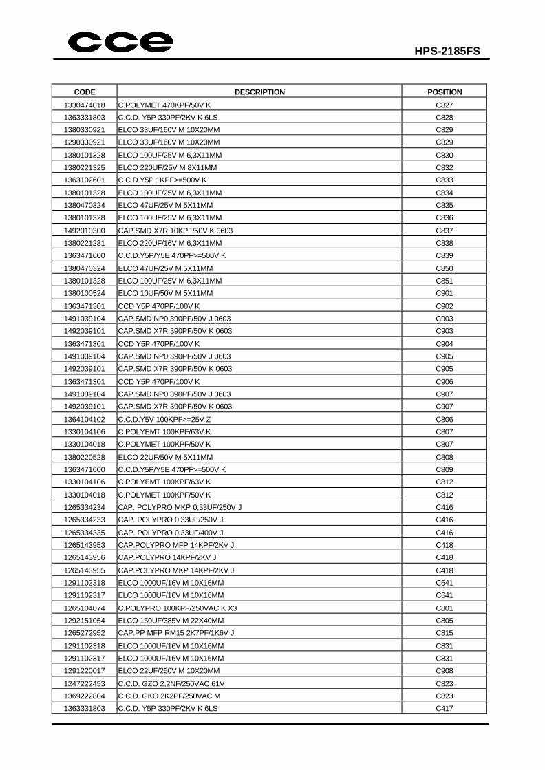
CODE DESCRIPTION POSITION
1330474018 C.POLYMET 470KPF/50V K C827
1363331803 C.C.D. Y5P 330PF/2KV K 6LS C828
1380330921 ELCO 33UF/160V M 10X20MM C829
1290330921 ELCO 33UF/160V M 10X20MM C829
1380101328 ELCO 100UF/25V M 6,3X11MM C830
1380221325 ELCO 220UF/25V M 8X11MM C832
1363102601 C.C.D.Y5P 1KPF>=500V K C833
1380101328 ELCO 100UF/25V M 6,3X11MM C834
1380470324 ELCO 47UF/25V M 5X11MM C835
1380101328 ELCO 100UF/25V M 6,3X11MM C836
1492010300 CAP.SMD X7R 10KPF/50V K 0603 C837
1380221231 ELCO 220UF/16V M 6,3X11MM C838
1363471600 C.C.D.Y5P/Y5E 470PF>=500V K C839
1380470324 ELCO 47UF/25V M 5X11MM C850
1380101328 ELCO 100UF/25V M 6,3X11MM C851
1380100524 ELCO 10UF/50V M 5X11MM C901
1363471301 CCD Y5P 470PF/100V K C902
1491039104 CAP.SMD NP0 390PF/50V J 0603 C903
1492039101 CAP.SMD X7R 390PF/50V K 0603 C903
1363471301 CCD Y5P 470PF/100V K C904
1491039104 CAP.SMD NP0 390PF/50V J 0603 C905
1492039101 CAP.SMD X7R 390PF/50V K 0603 C905
1363471301 CCD Y5P 470PF/100V K C906
1491039104 CAP.SMD NP0 390PF/50V J 0603 C907
1492039101 CAP.SMD X7R 390PF/50V K 0603 C907
1364104102 C.C.D.Y5V 100KPF>=25V Z C806
1330104106 C.POLYEMT 100KPF/63V K C807
1330104018 C.POLYMET 100KPF/50V K C807
1380220528 ELCO 22UF/50V M 5X11MM C808
1363471600 C.C.D.Y5P/Y5E 470PF>=500V K C809
1330104106 C.POLYEMT 100KPF/63V K C812
1330104018 C.POLYMET 100KPF/50V K C812
1265334234 CAP. POLYPRO MKP 0,33UF/250V J C416
1265334233 CAP. POLYPRO 0,33UF/250V J C416
1265334335 CAP. POLYPRO 0,33UF/400V J C416
1265143953 CAP.POLYPRO MFP 14KPF/2KV J C418
1265143956 CAP.POLYPRO 14KPF/2KV J C418
1265143955 CAP.POLYPRO MKP 14KPF/2KV J C418
1291102318 ELCO 1000UF/16V M 10X16MM C641
1291102317 ELCO 1000UF/16V M 10X16MM C641
1265104074 C.POLYPRO 100KPF/250VAC K X3 C801
1292151054 ELCO 150UF/385V M 22X40MM C805
1265272952 CAP.PP MFP RM15 2K7PF/1K6V J C815
1291102318 ELCO 1000UF/16V M 10X16MM C831
1291102317 ELCO 1000UF/16V M 10X16MM C831
1291220017 ELCO 22UF/250V M 10X20MM C908
1247222453 C.C.D. GZO 2,2NF/250VAC 61V C823
1369222804 C.C.D. GKO 2K2PF/250VAC M C823
1363331803 C.C.D. Y5P 330PF/2KV K 6LS C417
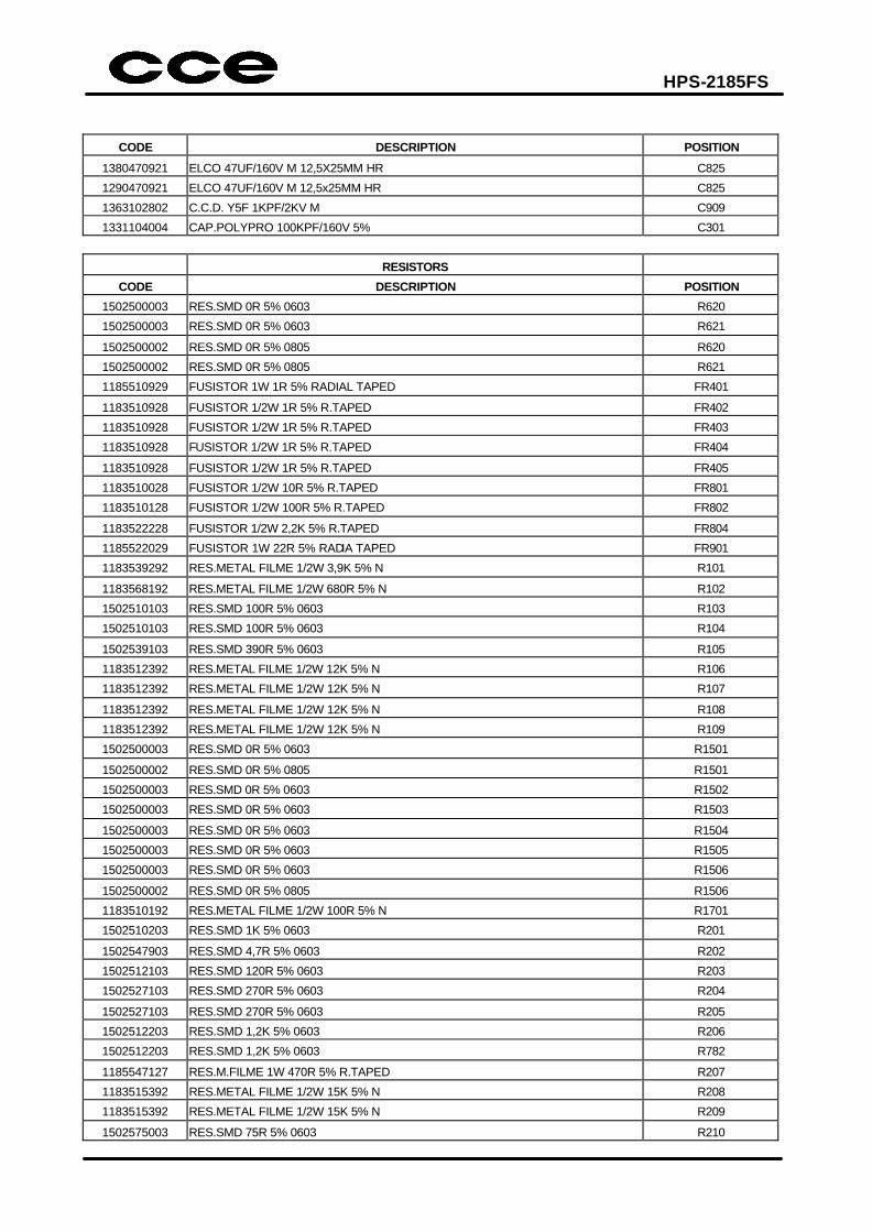
HPS-2185FS
CODE DESCRIPTION POSITION
1380470921 ELCO 47UF/160V M 12,5X25MM HR C825
1290470921 ELCO 47UF/160V M 12,5x25MM HR C825
1363102802 C.C.D. Y5F 1KPF/2KV M C909
1331104004 CAP.POLYPRO 100KPF/160V 5% C301
RESISTORS
CODE DESCRIPTION POSITION
1502500003 RES.SMD 0R 5% 0603 R620
1502500003 RES.SMD 0R 5% 0603 R621
1502500002 RES.SMD 0R 5% 0805 R620
1502500002 RES.SMD 0R 5% 0805 R621
1185510929 FUSISTOR 1W 1R 5% RADIAL TAPED FR401
1183510928 FUSISTOR 1/2W 1R 5% R.TAPED FR402
1183510928 FUSISTOR 1/2W 1R 5% R.TAPED FR403
1183510928 FUSISTOR 1/2W 1R 5% R.TAPED FR404
1183510928 FUSISTOR 1/2W 1R 5% R.TAPED FR405
1183510028 FUSISTOR 1/2W 10R 5% R.TAPED FR801
1183510128 FUSISTOR 1/2W 100R 5% R.TAPED FR802
1183522228 FUSISTOR 1/2W 2,2K 5% R.TAPED FR804
1185522029 FUSISTOR 1W 22R 5% RADIA TAPED FR901
1183539292 RES.METAL FILME 1/2W 3,9K 5% N R101
1183568192 RES.METAL FILME 1/2W 680R 5% N R102
1502510103 RES.SMD 100R 5% 0603 R103
1502510103 RES.SMD 100R 5% 0603 R104
1502539103 RES.SMD 390R 5% 0603 R105
1183512392 RES.METAL FILME 1/2W 12K 5% N R106
1183512392 RES.METAL FILME 1/2W 12K 5% N R107
1183512392 RES.METAL FILME 1/2W 12K 5% N R108
1183512392 RES.METAL FILME 1/2W 12K 5% N R109
1502500003 RES.SMD 0R 5% 0603 R1501
1502500002 RES.SMD 0R 5% 0805 R1501
1502500003 RES.SMD 0R 5% 0603 R1502
1502500003 RES.SMD 0R 5% 0603 R1503
1502500003 RES.SMD 0R 5% 0603 R1504
1502500003 RES.SMD 0R 5% 0603 R1505
1502500003 RES.SMD 0R 5% 0603 R1506
1502500002 RES.SMD 0R 5% 0805 R1506
1183510192 RES.METAL FILME 1/2W 100R 5% N R1701
1502510203 RES.SMD 1K 5% 0603 R201
1502547903 RES.SMD 4,7R 5% 0603 R202
1502512103 RES.SMD 120R 5% 0603 R203
1502527103 RES.SMD 270R 5% 0603 R204
1502527103 RES.SMD 270R 5% 0603 R205
1502512203 RES.SMD 1,2K 5% 0603 R206
1502512203 RES.SMD 1,2K 5% 0603 R782
1185547127 RES.M.FILME 1W 470R 5% R.TAPED R207
1183515392 RES.METAL FILME 1/2W 15K 5% N R208
1183515392 RES.METAL FILME 1/2W 15K 5% N R209
1502575003 RES.SMD 75R 5% 0603 R210
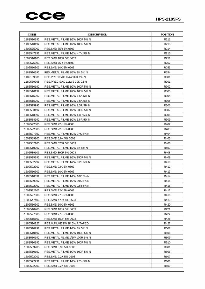
HPS-2185FS
CODE DESCRIPTION POSITION
1183510192 RES.METAL FILME 1/2W 100R 5% N R211
1183510192 RES.METAL FILME 1/2W 100R 5% N R213
1502575003 RES.SMD 75R 5% 0603 R214
1183547292 RES.METAL FILME 1/2W 4,7K 5% N R215
1502510103 RES.SMD 100R 5% 0603 R251
1502575003 RES.SMD 75R 5% 0603 R252
1502510303 RES.SMD 10K 5% 0603 R253
1183510292 RES.METAL FILME 1/2W 1K 5% N R254
1189139331 RES.PRECISAO 0,4W 39K 1% N R301
1189539395 RES.PRECISAO 1/2WS 39K 0,5% R301
1183510192 RES.METAL FILME 1/2W 100R 5% N R302
1183510192 RES.METAL FILME 1/2W 100R 5% N R303
1183515292 RES.METAL FILME 1/2W 1,5K 5% N R304
1183515292 RES.METAL FILME 1/2W 1,5K 5% N R305
1183515992 RES.METAL FILME 1/2W 1,5R 5% N R306
1183533192 RES.METAL.FILME 1/2W 330R 5% N R307
1183518992 RES.METAL FILME 1/2W 1,8R 5% N R308
1183518992 RES.METAL FILME 1/2W 1,8R 5% N R309
1502522303 RES.SMD 22K 5% 0603 R402
1502522303 RES.SMD 22K 5% 0603 R403
1183527392 RES.METAL FILME 1/2W 27K 5% N R404
1502539203 RES.SMD 3,9K 5% 0603 R405
1502582103 RES.SMD 820R 5% 0603 R406
1183510292 RES.METAL FILME 1/2W 1K 5% N R407
1502539103 RES.SMD 390R 5% 0603 R408
1183515192 RES.METAL FILME 1/2W 150R 5% N R409
1183582292 RES.METAL FILME 1/2W 8,2K 5% N R410
1502522303 RES.SMD 22K 5% 0603 R412
1502510303 RES.SMD 10K 5% 0603 R413
1183518392 RES.METAL FILME 1/2W 18K 5% N R414
1183539392 RES.METAL FILME 1/2W 39K 5% N R415
1183522092 RES.METAL FILME 1/2W 22R 5% N R416
1502522303 RES.SMD 22K 5% 0603 R417
1502527303 RES.SMD 27K 5% 0603 R418
1502547403 RES.SMD 470K 5% 0603 R419
1502510303 RES.SMD 10K 5% 0603 R420
1502510403 RES.SMD 100K 5% 0603 R421
1502527303 RES.SMD 27K 5% 0603 R422
1502515103 RES.SMD 150R 5% 0603 R426
1185510227 RES.M.FILME 1W 1K 5% R.TAPED R427
1183510292 RES.METAL FILME 1/2W 1K 5% N R507
1183510192 RES.METAL FILME 1/2W 100R 5% N R508
1183510192 RES.METAL FILME 1/2W 100R 5% N R509
1183510192 RES.METAL FILME 1/2W 100R 5% N R510
1502539203 RES.SMD 3,9K 5% 0603 R601
1183510192 RES.METAL FILME 1/2W 100R 5% N R606
1502522203 RES.SMD 2,2K 5% 0603 R607
1183522292 RES.METAL FILME 1/2W 2,2K 5% N R608
1502522203 RES.SMD 2,2K 5% 0603 R609
HPS-2185FS
CODE DESCRIPTION POSITION
1502510403 RES.SMD 100K 5% 0603 R610
1502510403 RES.SMD 100K 5% 0603 R611
1502510403 RES.SMD 100K 5% 0603 R612
1183510492 RES.METAL FILME 1/2W 100K 5% N R613
1183510292 RES.METAL FILME 1/2W 1K 5% N R614
1502182203 RES.SMD 8,2K 1% 0603 R615
1183510292 RES.METAL FILME 1/2W 1K 5% N R618
1502116103 RES.SMD 160R 1% 0603 R619
1502522203 RES.SMD 2,2K 5% 0603 R622
1502510403 RES.SMD 100K 5% 0603 R623
1502522203 RES.SMD 2,2K 5% 0603 R624
1502510403 RES.SMD 100K 5% 0603 R625
1183510192 RES.METAL FILME 1/2W 100R 5% N R626
1183510392 RES.METAL.FILME 1/2W 10K 5% N R629
1502539203 RES.SMD 3,9K 5% 0603 R630
1502510303 RES.SMD 10K 5% 0603 R631
1183568292 RES.METAL FILME 1/2W 6,8K 5% N R632
1502510403 RES.SMD 100K 5% 0603 R633
1183522292 RES.METAL FILME 1/2W 2,2K 5% N R634
1502510403 RES.SMD 100K 5% 0603 R635
1183522292 RES.METAL FILME 1/2W 2,2K 5% N R636
1502510403 RES.SMD 100K 5% 0603 R637
1502547203 RES.SMD 4,7K 5% 0603 R638
1502547203 RES.SMD 4,7K 5% 0603 R639
1502510403 RES.SMD 100K 5% 0603 R640
1183510392 RES.METAL.FILME 1/2W 10K 5% N R642
1183522292 RES.METAL FILME 1/2W 2,2K 5% N R643
1502510103 RES.SMD 100R 5% 0603 R644
1502510103 RES.SMD 100R 5% 0603 R645
1502510203 RES.SMD 1K 5% 0603 R646
1183515292 RES.METAL FILME 1/2W 1,5K 5% N R647
1502510203 RES.SMD 1K 5% 0603 R648
1502510203 RES.SMD 1K 5% 0603 R649
1502510203 RES.SMD 1K 5% 0603 R650
1502515203 RES.SMD 1,5K 5% 0603 R651
1502510203 RES.SMD 1K 5% 0603 R652
1502510203 RES.SMD 1K 5% 0603 R653
1502500003 RES.SMD 0R 5% 0603 R698TV
1183527192 RES.METAL FILME 1/2W 270R 5% N R654
1183510192 RES.METAL FILME 1/2W 100R 5% N R701
1183510192 RES.METAL FILME 1/2W 100R 5% N R702
1502556203 RES.SMD 5,6K 5% 0603 R703
1502510103 RES.SMD 100R 5% 0603 R566
1502547203 RES.SMD 4,7K 5% 0603 R704
1502510203 RES.SMD 1K 5% 0603 R705
1183547092 RES.METAL FILME 1/2W 47R 5% N R706
1183510192 RES.METAL FILME 1/2W 100R 5% N R709
1183510192 RES.METAL FILME 1/2W 100R 5% N R712
1183510192 RES.METAL FILME 1/2W 100R 5% N R713
HPS-2185FS
CODE DESCRIPTION POSITION
1183510192 RES.METAL FILME 1/2W 100R 5% N R719
1502510203 RES.SMD 1K 5% 0603 R721
1502547203 RES.SMD 4,7K 5% 0603 R722
1502547203 RES.SMD 4,7K 5% 0603 R723
1502547203 RES.SMD 4,7K 5% 0603 R744
1502547203 RES.SMD 4,7K 5% 0603 R745
1502522203 RES.SMD 2,2K 5% 0603 R749
1502518103 RES.SMD 180R 5% (0603) R774
1183547192 RES.METAL FILME 1/2W 470R 5% N R775
1502533103 RES.SMD 330R 5% 0603 R776
1502556103 RES.SMD 560R 5% N 0603 R777
1502510203 RES.SMD 1K 5% 0603 R778
1502547103 RESISTOR SMD 470R 5% 0603 R779
1183510192 RES.METAL FILME 1/2W 100R 5% N R781
1183527192 RES.METAL FILME 1/2W 270R 5% N R783
1183527492 RES.METAL FILME 1/2W 270K 5% N R803
1183522492 RES.METAL FILME 1/2W 220K 5% N R804
1183515492 RES.METAL FILME 1/2W 150K 5% N R806
1183527192 RES.METAL FILME 1/2W 270R 5% N R807
1183510292 RES.METAL FILME 1/2W 1K 5% N R809
1183556392 RES.METAL FILME 1/2W 56K 5% N R810
1183547292 RES.METAL FILME 1/2W 4,7K 5% N R811
1185522827 RES.M.FILME 1W 022R 5% R.TAPED R812
1183510992 RES.METAL FILME 1/2W 1R 5% N R813
1189111331 RES.PRECISAO 0,6W 113K 0,5% R816
1189511395 RES.PRECISAO 1/2WS 113K 0,5% R816
1189128231 RES.PRECISAO 0,6W 2,8K 0,5% R817
1189528295 RES.PRECISAO 1/2WS 2,8K 0,5% R817
1183515392 RES.METAL FILME 1/2W 15K 5% N R818
1183582192 RES.METAL FILME 1/2W 820R 5% N R820
1183568992 RES.METAL FILME 1/2W 6,8R 5% N R822
1183556192 RES.METAL FILME 1/2W 560R 5% N R823
1183533992 RES.METAL FILME 1/2W 3,3R 5% N R824
1183510092 RES.METAL FILME 1/2W 10R 5% N R655
1183510092 RES.METAL FILME 1/2W 10R 5% N R826
1183510092 RES.METAL FILME 1/2W 10R 5% N R827
1185547027 RES.M.FILME 1W 47R 5% R.TAPED R830
1183515292 RES.METAL FILME 1/2W 1,5K 5% N R831
1183510192 RES.METAL FILME 1/2W 100R 5% N R832
1183522392 RES.METAL FILME 1/2W 22K 5% N R833
1183510292 RES.METAL FILME 1/2W 1K 5% N R834
1502510303 RES.SMD 10K 5% 0603 R836
1502522203 RES.SMD 2,2K 5% 0603 R837
1502582103 RES.SMD 820R 5% 0603 R840
1502547203 RES.SMD 4,7K 5% 0603 R842
1183547392 RES.METAL.FILME 1/2W 47K 5% N R843
1183510292 RES.METAL FILME 1/2W 1K 5% N R844
1502522303 RES.SMD 22K 5% 0603 R845
1502556203 RES.SMD 5,6K 5% 0603 R847
HPS-2185FS
CODE DESCRIPTION POSITION
1502510303 RES.SMD 10K 5% 0603 R848
1183522092 RES.METAL FILME 1/2W 22R 5% N R852
1502518303 RES.SMD 18K 5% 0603 R853
1502547303 RES.SMD 47K 5% 0603 R854
1183510292 RES.METAL FILME 1/2W 1K 5% N R901
1502522003 RES.SMD 22R 5% 0603 R906
1502533103 RES.SMD 330R 5% 0603 R907
1502518203 RES.SMD 1,8K 5% 0603 R908
1183510292 RES.METAL FILME 1/2W 1K 5% N R909
1502522003 RES.SMD 22R 5% 0603 R915
1502533103 RES.SMD 330R 5% 0603 R916
1502518203 RES.SMD 1,8K 5% 0603 R917
1183510292 RES.METAL FILME 1/2W 1K 5% N R918
1502533003 RES.SMD 33R 5% 0603 R920
1502522003 RES.SMD 22R 5% 0603 R924
1502533103 RES.SMD 330R 5% 0603 R925
1502518203 RES.SMD 1,8K 5% 0603 R926
1183510292 RES.METAL FILME 1/2W 1K 5% N R927
1183533092 RES.METAL FILME 1/2W 33R 5% N R929
1183533092 RES.METAL FILME 1/2W 33R 5% N R930
1183518492 RES.METAL FILME 1/2W 180K 5% N R931
1183518492 RES.METAL FILME 1/2W 180K 5% N R932
1502547203 RES.SMD 4,7K 5% 0603 RU746
1183568549 RESISTOR ALTA TENSAO 1/2W 6M8 J R815
1183668519 RES. COMPOSIÇAO 1/2W 6,8M K R815
1183510192 RES.METAL FILME 1/2W 100R 5% N R641
1183547219 RES. COMPOSICAO 1/2W 4,7K 10% R423
1183647249 RESISTOR ALTA TENSAO 1/2W 4K7 K R423
1125707400 RES.COEF.NEG.NTC 10R NTC801
1184515325 RES.M.FILME 2W 15K 5% D.KINK R913
1184515325 RES.M.FILME 2W 15K 5% D.KINK R922
1185533025 RES.M.FILME 1W 33R 5% D.KINK R113
1185533012 RES.METAL FILME >= 1W 33R 5 R113
1187556225 RES.M.FILME 3W 5,6K 5% D.KINK R411
1184515325 RES.M.FILME 2W 15K 5% D.KINK R904
1183615249 RESISTOR ALTA TENSAO 1/2W 1K5 K R910
1183615249 RESISTOR ALTA TENSAO 1/2W 1K5 K R919
1183615249 RESISTOR ALTA TENSAO 1/2W 1K5 K R928
1183615219 RES.COMPOS.1/2W 1,5K 5% N R910
1183615219 RES.COMPOS.1/2W 1,5K 5% N R919
1183615219 RES.COMPOS.1/2W 1,5K 5% N R928
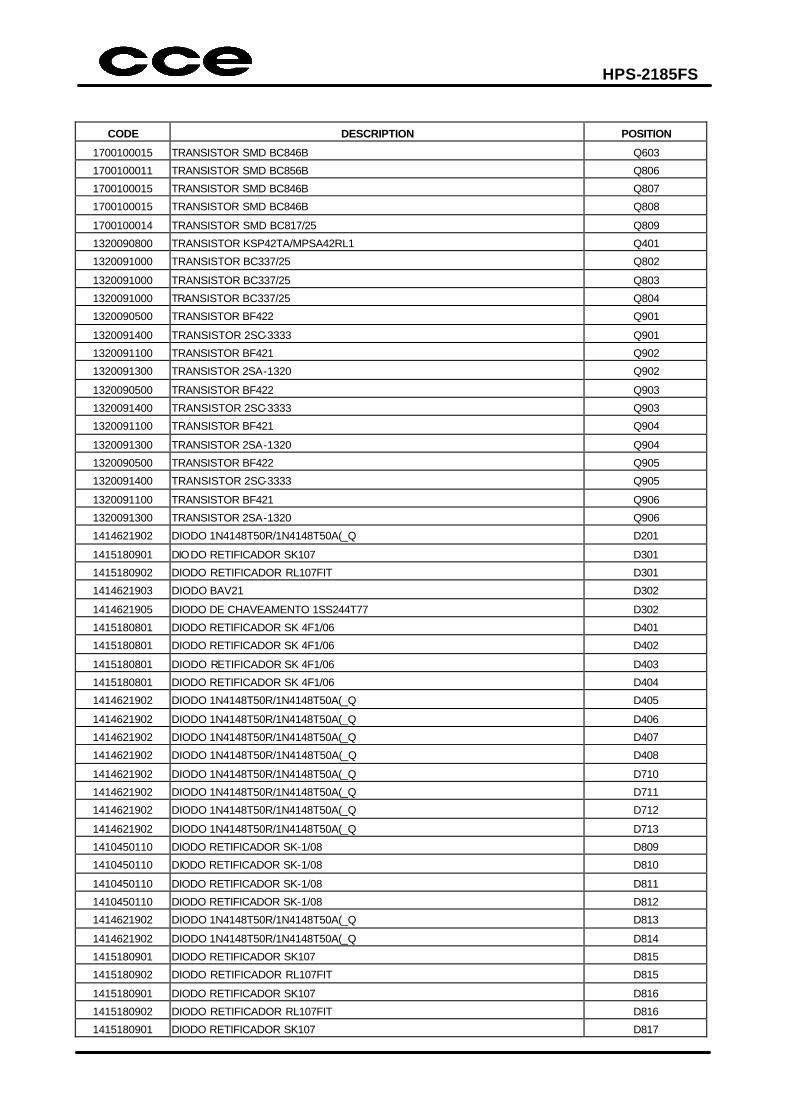
SEMICONDUCTORS
CODE DESCRIPTION POSITION
1700100015 TRANSISTOR SMD BC846B Q201
1700100011 TRANSISTOR SMD BC856B Q403
1700100015 TRANSISTOR SMD BC846B Q404
1700100015 TRANSISTOR SMD BC846B Q601
1700100015 TRANSISTOR SMD BC846B Q602
HPS-2185FS
CODE DESCRIPTION POSITION
1700100015 TRANSISTOR SMD BC846B Q603
1700100011 TRANSISTOR SMD BC856B Q806
1700100015 TRANSISTOR SMD BC846B Q807
1700100015 TRANSISTOR SMD BC846B Q808
1700100014 TRANSISTOR SMD BC817/25 Q809
1320090800 TRANSISTOR KSP42TA/MPSA42RL1 Q401
1320091000 TRANSISTOR BC337/25 Q802
1320091000 TRANSISTOR BC337/25 Q803
1320091000 TRANSISTOR BC337/25 Q804
1320090500 TRANSISTOR BF422 Q901
1320091400 TRANSISTOR 2SC-3333 Q901
1320091100 TRANSISTOR BF421 Q902
1320091300 TRANSISTOR 2SA-1320 Q902
1320090500 TRANSISTOR BF422 Q903
1320091400 TRANSISTOR 2SC-3333 Q903
1320091100 TRANSISTOR BF421 Q904
1320091300 TRANSISTOR 2SA-1320 Q904
1320090500 TRANSISTOR BF422 Q905
1320091400 TRANSISTOR 2SC-3333 Q905
1320091100 TRANSISTOR BF421 Q906
1320091300 TRANSISTOR 2SA-1320 Q906
1414621902 DIODO 1N4148T50R/1N4148T50A(_Q D201
1415180901 DIODO RETIFICADOR SK107 D301
1415180902 DIODO RETIFICADOR RL107FIT D301
1414621903 DIODO BAV21 D302
1414621905 DIODO DE CHAVEAMENTO 1SS244T77 D302
1415180801 DIODO RETIFICADOR SK 4F1/06 D401
1415180801 DIODO RETIFICADOR SK 4F1/06 D402
1415180801 DIODO RETIFICADOR SK 4F1/06 D403
1415180801 DIODO RETIFICADOR SK 4F1/06 D404
1414621902 DIODO 1N4148T50R/1N4148T50A(_Q D405
1414621902 DIODO 1N4148T50R/1N4148T50A(_Q D406
1414621902 DIODO 1N4148T50R/1N4148T50A(_Q D407
1414621902 DIODO 1N4148T50R/1N4148T50A(_Q D408
1414621902 DIODO 1N4148T50R/1N4148T50A(_Q D710
1414621902 DIODO 1N4148T50R/1N4148T50A(_Q D711
1414621902 DIODO 1N4148T50R/1N4148T50A(_Q D712
1414621902 DIODO 1N4148T50R/1N4148T50A(_Q D713
1410450110 DIODO RETIFICADOR SK-1/08 D809
1410450110 DIODO RETIFICADOR SK-1/08 D810
1410450110 DIODO RETIFICADOR SK-1/08 D811
1410450110 DIODO RETIFICADOR SK-1/08 D812
1414621902 DIODO 1N4148T50R/1N4148T50A(_Q D813
1414621902 DIODO 1N4148T50R/1N4148T50A(_Q D814
1415180901 DIODO RETIFICADOR SK107 D815
1415180902 DIODO RETIFICADOR RL107FIT D815
1415180901 DIODO RETIFICADOR SK107 D816
1415180902 DIODO RETIFICADOR RL107FIT D816
1415180901 DIODO RETIFICADOR SK107 D817
HPS-2185FS
CODE DESCRIPTION POSITION
1415180902 DIODO RETIFICADOR RL107FIT D817
1414621902 DIODO 1N4148T50R/1N4148T50A(_Q D818
1414621902 DIODO 1N4148T50R/1N4148T50A(_Q D819
1414621902 DIODO 1N4148T50R/1N4148T50A(_Q D820
1414621902 DIODO 1N4148T50R/1N4148T50A(_Q D823
1414621902 DIODO 1N4148T50R/1N4148T50A(_Q D899
1414621902 DIODO 1N4148T50R/1N4148T50A(_Q D901
1414621902 DIODO 1N4148T50R/1N4148T50A(_Q D902
1414621902 DIODO 1N4148T50R/1N4148T50A(_Q D903
1414621902 DIODO 1N4148T50R/1N4148T50A(_Q D904
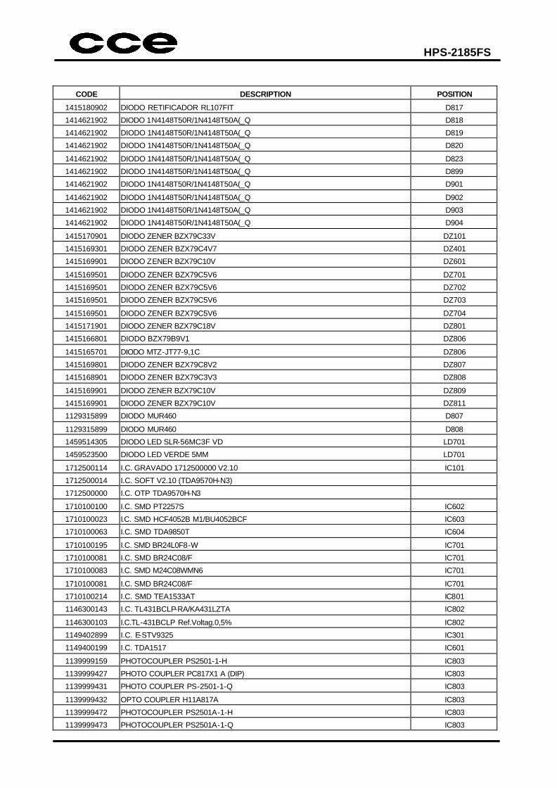
1415170901 DIODO ZENER BZX79C33V DZ101
1415169301 DIODO ZENER BZX79C4V7 DZ401
1415169901 DIODO ZENER BZX79C10V DZ601
1415169501 DIODO ZENER BZX79C5V6 DZ701
1415169501 DIODO ZENER BZX79C5V6 DZ702
1415169501 DIODO ZENER BZX79C5V6 DZ703
1415169501 DIODO ZENER BZX79C5V6 DZ704
1415171901 DIODO ZENER BZX79C18V DZ801
1415166801 DIODO BZX79B9V1 DZ806
1415165701 DIODO MTZ-JT77-9,1C DZ806
1415169801 DIODO ZENER BZX79C8V2 DZ807
1415168901 DIODO ZENER BZX79C3V3 DZ808
1415169901 DIODO ZENER BZX79C10V DZ809
1415169901 DIODO ZENER BZX79C10V DZ811
1129315899 DIODO MUR460 D807
1129315899 DIODO MUR460 D808
1459514305 DIODO LED SLR-56MC3F VD LD701
1459523500 DIODO LED VERDE 5MM LD701
1712500114 I.C. GRAVADO 1712500000 V2.10 IC101
1712500014 I.C. SOFT V2.10 (TDA9570H-N3)
1712500000 I.C. OTP TDA9570H-N3
1710100100 I.C. SMD PT2257S IC602
1710100023 I.C. SMD HCF4052B M1/BU4052BCF IC603
1710100063 I.C. SMD TDA9850T IC604
1710100195 I.C. SMD BR24L0F8-W IC701
1710100081 I.C. SMD BR24C08/F IC701
1710100083 I.C. SMD M24C08WMN6 IC701
1710100081 I.C. SMD BR24C08/F IC701
1710100214 I.C. SMD TEA1533AT IC801
1146300143 I.C. TL431BCLP-RA/KA431LZTA IC802
1146300103 I.C.TL-431BCLP Ref.Voltag.0,5% IC802
1149402899 I.C. E-STV9325 IC301
1149400199 I.C. TDA1517 IC601
1139999159 PHOTOCOUPLER PS2501-1-H IC803
1139999427 PHOTO COUPLER PC817X1 A (DIP) IC803
1139999431 PHOTO COUPLER PS-2501-1-Q IC803
1139999432 OPTO COUPLER H11A817A IC803
1139999472 PHOTOCOUPLER PS2501A-1-H IC803
1139999473 PHOTOCOUPLER PS2501A-1-Q IC803
HPS-2185FS
CODE DESCRIPTION POSITION
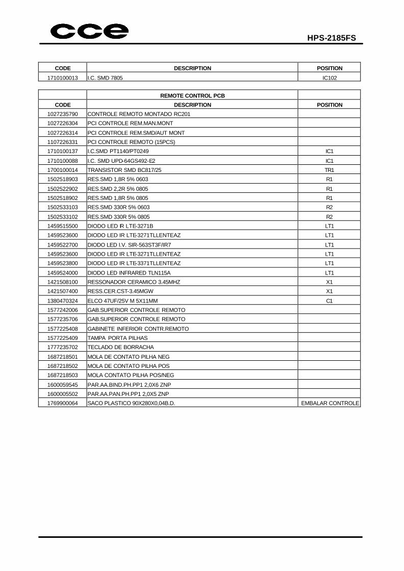
1710100013 I.C. SMD 7805 IC102
REMOTE CONTROL PCB
CODE DESCRIPTION POSITION
1027235790 CONTROLE REMOTO MONTADO RC201
1027226304 PCI CONTROLE REM.MAN.MONT
1027226314 PCI CONTROLE REM.SMD/AUT MONT
1107226331 PCI CONTROLE REMOTO (15PCS)
1710100137 I.C.SMD PT1140/PT0249 IC1
1710100088 I.C. SMD UPD-64GS492-E2 IC1
1700100014 TRANSISTOR SMD BC817/25 TR1
1502518903 RES.SMD 1,8R 5% 0603 R1
1502522902 RES.SMD 2,2R 5% 0805 R1
1502518902 RES.SMD 1,8R 5% 0805 R1
1502533103 RES.SMD 330R 5% 0603 R2
1502533102 RES.SMD 330R 5% 0805 R2
1459515500 DIODO LED IR LTE-3271B LT1
1459523600 DIODO LED IR LTE-3271TLLENTEAZ LT1
1459522700 DIODO LED I.V. SIR-563ST3F/IR7 LT1
1459523600 DIODO LED IR LTE-3271TLLENTEAZ LT1
1459523800 DIODO LED IR LTE-3371TLLENTEAZ LT1
1459524000 DIODO LED INFRARED TLN115A LT1
1421508100 RESSONADOR CERAMICO 3.45MHZ X1
1421507400 RESS.CER.CST-3.45MGW X1
1380470324 ELCO 47UF/25V M 5X11MM C1
1577242006 GAB.SUPERIOR CONTROLE REMOTO
1577235706 GAB.SUPERIOR CONTROLE REMOTO
1577225408 GABINETE INFERIOR CONTR.REMOTO
1577225409 TAMPA PORTA PILHAS
1777235702 TECLADO DE BORRACHA
1687218501 MOLA DE CONTATO PILHA NEG
1687218502 MOLA DE CONTATO PILHA POS
1687218503 MOLA CONTATO PILHA POS/NEG
1600059545 PAR.AA.BIND.PH.PP1 2,0X6 ZNP
1600005502 PAR.AA.PAN.PH.PP1 2,0X5 ZNP
1769900064 SACO PLASTICO 90X280X0,04B.D. EMBALAR CONTROLE
HPS-2185FS
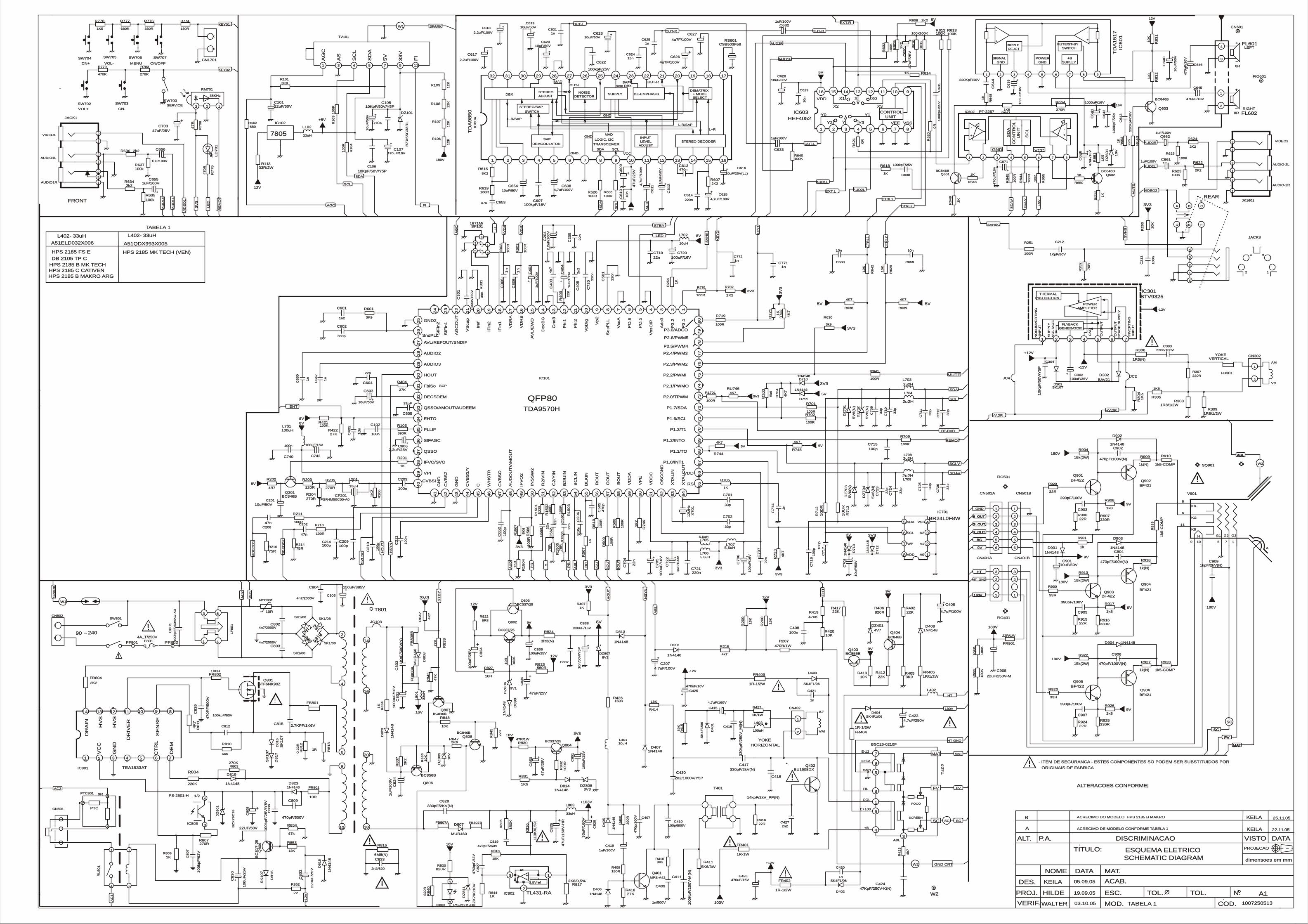
6. ELECTRICAL SCHEME 6.1 MAIN AND REMOTE CONTROL PCB 7. SILKTOP AND SOLDERS 7.1 MAIN PCB 7.2 REMOTE CONTROL PCB 8. EXPLODED VIEW 9. BLOCK DIAGRAM
100p100p
75R75R
5V5V
10n10n
5V5V4K74K7
10n10n
10
K1
0K
4K74K7
10
K1
0K
47k47k
18K18K
1N
41
48
1N
41
48
BC
81
7-2
5B
C8
17
-25
22
0u
F/2
5V
22
0u
F/2
5V
2222
10
0u
F/2
5V
10
0u
F/2
5V
SK
10
7S
K1
07
10KpF/50V/Y5P10KpF/50V/Y5P
18
0K
18
0K
12
K1
2K
12
K1
2K
12
K1
2K
12
K1
2K
10
0n
10
0n
10
K1
0K
100R100R
1K1K
100K100K100K100K
4u7F/100V4u7F/100V
100R100R
47n47n
2K22K2
10uF/50V10uF/50V
10uF/25V(LL)10uF/25V(LL)
4,7uF/100V4,7uF/100V
8K28K2
100K100K
10
n1
0n
100K100K
CSB503F58CSB503F58
100R100R
470n470n
100kpF/16V100kpF/16V
10uF/50V10uF/50V
1n1n
1n1n
2.2uF/100V2.2uF/100V
2K22K2
220n220n
1N
41
48
1N
41
48
1N
41
48
1N
41
48
180R180R
220KpF/16V220KpF/16V
270R270R
75
R7
5R
75
R7
5R
75
R7
5R
470uF/16V470uF/16V
100K100K
100K100K
10
0R
10
0R
10
uF
/50
V1
0u
F/5
0V
47
uF
/25
V4
7u
F/2
5V
2K22K2
10uF/50V10uF/50V
10
0R
10
0R
10
0R
10
0R
1uF/100V1uF/100V
1uF/100V1uF/100V
2k22k2
100k100k
100k100k
220n220n
1u
F/1
00
V1
uF
/10
0V
75R75R
22
0K
pF
/16
V2
20
Kp
F/1
6V
4k74k7
10
0R
10
0R
2k22k2
1R8/1/2W1R8/1/2W
1R8/1/2W1R8/1/2W
4K
74
K7
10
0R
10
0R
5K
65
K6
0R
0R
100R100R
0R
0R
100R100R
3V33V3
1KpF/50V1KpF/50V
33R/2W33R/2W
100R100R
3V33V3
10uF/50V10uF/50V
1R/1/2W1R/1/2W
1N41481N4148
4,7uF/100V4,7uF/100V
3K93K9
22K22K
4V74V7
820R820R
BC846BBC846B
22K22K10K10K
BC856BBC856B
10K10K100n100n
75
R7
5R
100R100R
1K
1K
27K27K
4k7
4k7
100R100R
47
0R
47
0R
15uH15uH
BC846BBC846BTPSR4M50C00-A0TPSR4M50C00-A0270R270R
1K
21
K2
120R120R 270R270R4R74R7
4u7F/100V4u7F/100V
22R22R
BF422BF422
390pF/100V390pF/100V
470pF/100V(N)470pF/100V(N)
22R22R
1k5-COMP1k5-COMP
15k(2W)15k(2W)
1k81k8
330R330R
1k(N)1k(N)
33R33R
1N41481N4148
160R160R
BF421BF421
BAV21BAV21
4K74K7
BF421BF421
BF422BF422
22uF/250V-M22uF/250V-M
390pF/100V390pF/100V
330R330R
150R150R
10uH10uH
1K
51
K5
15k(2W)15k(2W)
2K22K2
1N41481N4148
10
0u
F/1
6V
10
0u
F/1
6V
2u2H2u2H
5K6/3W5K6/3W
150R150R
10
uF
/50
V1
0u
F/5
0V
22
K2
2K
6k8
6k8
BC846BBC846B
10
K1
0K
1K51K5
10
0K
pF
/25
V1
00
Kp
F/2
5V
2n22n2
1000uF/16V1000uF/16V
330R330R
10uF/50V10uF/50V
15
K1
5K
100p/500V100p/500V
470R/1W470R/1W
10
n1
0n
10
K1
0K
10K10K
22
K2
2K 100uH100uH
5K65K6
39
0R
39
0R
10
0R
10
0R
10
V1
0V
2K
22
K2
1u
F/1
00
V1
uF
/10
0V
1N
41
48
1N
41
48
1K
1K
1uF/100V1uF/100V
BC856BBC856B
47n47n
47
K4
7K
10
0R
10
0R
100p100p
10
0R
10
0R
1K/1W1K/1W
2u2H2u2H
10
0R
10
0R
10
0p
10
0p
2u2H2u2H
2u2H2u2H
100K100K
1K1K
4K
74
K7
27K27K
4K
74
K7
10
0p
10
0p
10
Kp
F/5
0V
/Y5
P1
0K
pF
/50
V/Y
5P
33
p3
3p
33
p3
3p
1N
41
48
1N
41
48
BR24L0F8WBR24L0F8W
10
0R
10
0R
33
p3
3p
33
p3
3p
4K
74
K7
10
n1
0n
10uH10uH
10uF/50V10uF/50V
100p100p
5V
6(N
)5V
6(N
)
5V
6(N
)5V
6(N
)
22
K2
2K
BZ
X5
5C
33
RL
BZ
X5
5C
33
RL
33
p3
3p
33
p3
3p 3
3p
33
p
10
0R
10
0R
1n
1n
10
0R
10
0R
SK107SK107
33
p3
3p
18
0K
18
0K
22
n2
2n
100kpF/25V100kpF/25V
BC846BBC846B
5,6uH5,6uH
10KpF/50V/Y5P10KpF/50V/Y5P
22uH22uH
1k1k
1n
1n
TEA1533ATTEA1533AT
470pF/100V(N)470pF/100V(N)
5,6uH5,6uH
10
uF
/50
V1
0u
F/5
0V
10
0kp
F/6
3V
10
0kp
F/6
3V
2.7KPF/1K6V2.7KPF/1K6V
100uF/25V100uF/25V
680680
1n
1n
100kpF/63V100kpF/63V
MUR460MUR460
1N41481N4148
270K270K
10
n/5
0V
/Y5
P1
0n
/50
V/Y
5P
4K
74
K7
4n7/2000V4n7/2000V
SK1/08SK1/08
220uF/16V220uF/16V
100R100R
12
MH
z1
2M
Hz
5V
6(N
)5V
6(N
)
8V28V2
22R/1W22R/1W
5,6uH5,6uH
47n47n
1N41481N4148
3V33V3
22uF/50V22uF/50V
15k(2W)15k(2W)
1N41481N4148
10
0u
F/2
5V
10
0u
F/2
5V
47
uF
/25
V4
7u
F/2
5V
1k(N)1k(N)
1n/500V1n/500V
100R100R
10
0R
10
0R
1K51K5
47R/1W47R/1WBC337/25BC337/25
5V
6(N
)5
V6
(N)
330R330R
SK1/08SK1/08
100kpF/25V100kpF/25V
1k81k8
9V19V1
470pF/500V470pF/500V
100uF/35V100uF/35V
0.2
2R
0.2
2R
1k(N)1k(N)
6R86R8
4n7/2000V4n7/2000V
33
uH
33
uH
1k5
-CO
MP
1k5
-CO
MP
6M8(N)6M8(N)
22R22R
100n100n
270R270R
33pF33pF
330pF/2KV(N)330pF/2KV(N)
470pF/100V(N)470pF/100V(N)
SK
10
7S
K1
07
4,7
uF
/10
0V
4,7
uF
/10
0V
330p330p
10R10R
1n21n2
150uF/385V150uF/385V
33uH33uH
SK1/08SK1/08
2n2/6202n2/620
47uF/25V47uF/25V
680R680R
390pF/100V390pF/100V
1K1K
1K
pF
/50
0V
(N)
1K
pF
/50
0V
(N)
27K27K
SK1/08SK1/08
470uF/16V470uF/16V
33
uF
/16
0V
33
uF
/16
0V
47
0p
/10
0V
47
0p
/10
0V
56K56K
BF422BF422
47
uF
/16
0V
-HR
47
uF
/16
0V
-HR
SK
107
SK
107
2K22K2
1kpF/2kV(N)1kpF/2kV(N)
1K1K
1R1R
47
0P
F/5
00
V47
0P
F/5
00
V
100uF/16V100uF/16V
BZ
X7
9C
10
VB
ZX
79
C1
0V
22UF/50V22UF/50V
1K1K
10R10R
22
K2
2K
47
0kp
F/6
3V
47
0kp
F/6
3V
10
0kp
F/2
50
VA
C-X
31
00
kp
F/2
50
VA
C-X
3
10uF/50V10uF/50V
4A_T/250V4A_T/250V
BF421BF421
1N41481N4148
10R10R
1K
1K
1n1n
1K
1K
1N41481N4148
10
0kp
F/2
5V
10
0kp
F/2
5V
1N41481N4148
3K93K9
10
uF
/50
V1
0u
F/5
0V
BZ
X7
9C
18
BZ
X7
9C
18
1n
1n
220K220K
5k6
5k6
10
0R
10
0R
1R-1W1R-1W
1N41481N4148
10
0K
pF
/25
0V
-M(N
)10
0K
pF
/25
0V
-M(N
)
1n1n
470uF/16V470uF/16V
SK4F1/06SK4F1/06
47KpF/250V-K(N)47KpF/250V-K(N)
BSC25-0210FBSC25-0210F
3k93k9
22R22R
100R100R
1n1n
33
0kp
F/2
50
V_
M(N
)3
30
kp
F/2
50
V_
M(N
)
2n2/1000V/Y5P2n2/1000V/Y5P
14kpF/2kV_PP(N)14kpF/2kV_PP(N)
330pF/2kV(N)330pF/2kV(N)
220n/100V220n/100V
4,7uF/160V4,7uF/160V
39
K3
9K
22n22n
22
0n
22
0n
SK
4F
1/0
6S
K4
F1
/06
1R-1/2W1R-1/2W
1R-1/2W1R-1/2W
BU1508DXBU1508DX
SK4F1/06SK4F1/06
22
0n
22
0n2
n2
2n
2
47
0u
F/1
6V
47
0u
F/1
6V
8K28K2
1u
F/1
00
V1
uF
/10
0V4
n7
4n
71N41481N4148
1R5(N)1R5(N)
33R33R
1u
F/1
00
V1
uF
/10
0V
2,2
uF
/10
0V
2,2
uF
/10
0V
39
K3
9K
10
0R
10
0R
15K15K
22
n2
2n
470uF/16V470uF/16V
1k5-COMP1k5-COMP
33R33R
1k81k8
+103V+103V
10
0n
/16
0V
10
0n
/16
0V
22n22n
10
0p
10
0p
2,2uF/25V2,2uF/25V
47
uF
/25
V4
7u
F/2
5V
SK4F1/06SK4F1/06
10
n1
0n
2.2uF/100V2.2uF/100V
10uF/50V10uF/50V
3K93K9
15n15n
100uF/16V100uF/16V
4,7uF/100V4,7uF/100V
390R390R
1N41481N4148
2K
22
K2
47kpF/250V47kpF/250V
47
0p
47
0p
1uF/100V1uF/100V
15
0K
15
0K
1K1K
100uH100uH
MPS-A42MPS-A42
1871M/1871M/
82
0R
82
0R
22K22K
10
0p
10
0p
10
0n
10
0n
BC337/25BC337/25
10
0kp
F/2
5V
/Y5
V1
00
kp
F/2
5V
/Y5
V
10
0u
F/2
5V
10
0u
F/2
5V
100n100n
STF6NK90ZSTF6NK90Z
22
n2
2n
100R100R
MU
R4
60
MU
R4
60
22
n2
2n
1R-1/2W1R-1/2W
100n100n
4,7uF/250V4,7uF/250V
560R560R
10
R1
0R
BC337/25BC337/25
BC846BBC846B
4n7/2000V4n7/2000V
4,7uF/100V4,7uF/100V
10
0R
10
0R
3R3(N)3R3(N)
820R820R
11
3K
/0,5
%11
3K
/0,5
%
15
K1
5K
1uF/100V1uF/100V
1K1K
22
n2
2n
470K470K
330R330R
2K
22
K2
10
0uF
/16
V1
00
uF
/16
V
22
n2
2n
1N41481N4148
2K8/0,5%2K8/0,5%
33p33p
18K18K
47
R4
7R
33p33p
1K51K5
1n
1n
10
0u
F/1
6V
10
0u
F/1
6V
10
00
uF
/16
V1
00
0u
F/1
6V
100R100R
1N41481N4148
47uF/25V47uF/25V
470R470R
1K21K2
1N
41
48
1N
41
48
4K74K7
4K74K7
1n1n
10
0K
10
0K
1uF/100V1uF/100V
100K100K
1uF/100V1uF/100V
1K1K
1K51K5
1K
1K
1K
1K
1K1K
1K
51
K5
1K
1K
1K
1K
BC846BBC846B BC846BBC846B
270R270R
47
uF
/16
V4
7u
F/1
6V
10
V1
0V
47
0u
F/1
6V
47
0u
F/1
6V
10
R1
0R
AUD2RAUD2R
AUD2RAUD2R
+V.DR+V.DR
5V5V
5V5V
3V33V3
3V33V3
3V33V3
3V33V3
3V
33
V3
3V33V3
3V33V3
DT-DVDDT-DVD
SCSCSCSC
R_OUTR_OUTR_OUTR_OUT
G_OUTG_OUTG_OUTG_OUT
AUD1RAUD1R
AU
D1
RA
UD
1R
REMOTREMOT
RE
MO
TR
EM
OT
B_OUTB_OUTB_OUTB_OUT
MATMATMATMAT
FVFVFVFV
AUD2LAUD2L
AUD2LAUD2L
SP
AR
KS
PA
RK
SPARKSPARK
COLCOL
BCBCBCBC
BC
BC
BO
UT
BO
UT
-V.DR-V.DR
GO
UT
GO
UT
RO
UT
RO
UT
SD
AS
DA
SDASDA
SDASDA
12V12V
12V12V
12V12V
12V12V
12V12V
AG
CA
GC
AGCAGC
8V8V
8V8V
8V8V
8V8V
8V8V
FILFIL
GNDGND
GNDGND
HTHTHTHT
HTHT
SC
LS
CL
SCLSCL
SCLSCL
OUT-LOUT-L
OUT-LOUT-L
-12V-12V
-12V-12V
-12V-12V
STBYSTBY
180V180V180V180V
180V180V
OUT-ROUT-R OUT-ROUT-R
E+12E+12
SCPSCP
E-12E-12
HO
UT
HO
UT
HO
UT
HO
UT
+12V+12V
+12V+12V
AUD1LAUD1L
AU
D1
LA
UD
1L
HS
YN
HS
YN
HS
YN
HS
YN
+V
DR
+V
DR
-VD
R-V
DR
+B+B
FI
FI
FIFI
ABLABLABLABL
AB
LA
BL
AB
LA
BL
ABLABL
E+180E+180
KEY01KEY01
LE
DL
ED
LEDLED
AU
DA
UD
EHTEHT
EH
TE
HT
CT
RL
1C
TR
L1
CTRL1CTRL1
CT
RL
2C
TR
L2
CTRL2CTRL2
16V16V
16V16V
16V16V
16V16V
9V9V
9V9V
9V9V
9V9V
HT_GNDHT_GND
3V33V3
3V33V3
VID
EO
D2
VID
EO
D2
HT GNDHT GND
GND CRTGND CRT
EXT.REXT.R
EXT.LEXT.L
YY
PR
PR
PB
PB
+5V+5V
+5
V+
5V
5V5V5V5V
3V33V3
SC
LV
SC
LV
SD
AV
SD
AV
MUTEMUTE
3V
33
V3
180V180V
MU
TE
MU
TE
ST
BY
ST
BY
AC
1A
C1
AC
2A
C2
3V33V3
KE
Y2
KE
Y2
KEY02KEY02
VIDEO2VIDEO2
VID
EO
1V
IDE
O1
AMAM
VDVD
VID
EO
D1
VID
EO
D1
AC
1A
C1
AC2AC2
KE
Y1
KE
Y1
SV
HS
SV
HS
SV
HS
SV
HS
SV
HS
CS
VH
SC
SVHSCSVHSC
+1
2V
+1
2V
AU
DA
UD
W2W2
MATMAT
FVFV
SCSCSCSC
9V9V
9V9V
9V9V
9V9V
9V9V
180V180V
180V180V
180V180V
180V180V
180V180V
**
103V103V
SDAVSDAV
SCLVSCLV
W1W1
VIDEO2VIDEO2
AUDIO-2LAUDIO-2L
AUDIO-2RAUDIO-2R
LEFTLEFT
RIGHTRIGHT
SCSC
VMVM
AZAZ
W2W2
W1W1
CN402CN402
C214C214
R210R210
C660C660
R638R638
C659C659
R6
29
R6
29
R639R639
R6
42
R6
42
R854R854
R853R853
D8
18
D8
18
Q8
09
Q8
09
C8
32
C8
32
R852R852
C8
30
C8
30
D8
15
D8
15
PTC801PTC801
C105C105
R9
32
R9
32
R106R106
R107R107
R108R108
R109R109
C2
13
C2
13
R2
53
R2
53
R251R251
R618R618
R612R612
FL601FL601
FL602FL602
R6
10
R6
10
C627C627
IC603IC603
IC6
04
IC6
04
R606R606
C653C653
R608R608C619C619
C616C616
C608C608
R615R615
CN601CN601R613R613
C6
10
C6
10
R6
11
R6
11RS601RS601
R626R626
C613C613
C607C607
C654C654
C621C621
C625C625
C617C617
R624R624
C614C614
D7
12
D7
12
D7
13
D7
13
R774R774
C6
44
C6
44
FIO601FIO601
R783R783
R1
50
6R
15
06
R1
50
5R
15
05
R1
50
4R
15
04
C107C107
R623R623
R625R625
R15
03
R15
03
C6
12
C6
12
C6
30
C6
30
R622R622
C628C628
R1
50
2R
15
02
R64
4R
64
4
C662C662
C661C661
R636R636
R635R635
R637R637
C721C721
C4
01
C4
01
R214R214
C6
43
C6
43
R215R215
R64
5R
64
5
R634R634
FB301FB301
R309R309
R308R308
SW700SW700
R7
22
R7
22
R15
01
R15
01
R1
50
7R
15
07
R6
20
R6
20
R1701R1701
R6
21
R6
21
R702R702
C212C212
R113R113
R719R719
C623C623
FR405FR405
D408D408
C406C406
R405R405
R402R402
DZ401DZ401
R406R406
Q404Q404
R412R412R413R413
Q403Q403
R420R420C408C408
R2
52
R2
52
R641R641
R2
54
R2
54
R404R404
R4
23
R4
23
R709R709
R7
75
R7
75
L201L201
Q201Q201CF201CF201R204R204
R2
06
R2
06
R203R203 R205R205R202R202
C626C626
FIO501FIO501
R906R906
Q903Q903
C907C907
C904C904
R924R924
R928R928
R922R922
R926R926
R925R925
R927R927
R920R920
D902D902
R619R619
Q904Q904
D302D302
R744R744
Q906Q906
Q905Q905
C908C908
C903C903
R907R907
R426R426
L401L401
R3
04
R3
04
R913R913
R607R607
RL
80
1R
L8
01
D901D901
CN501BCN501B
CN401BCN401B
IC602IC602
C6
39
C6
39
L709L709
R411R411
R409R409
IC101IC101
C6
40
C6
40
R6
43
R6
43
R6
32
R6
32
Q603Q603
R6
31
R6
31
R305R305
C6
42
C6
42
C427C427
C6
41
C6
41
R307R307
IC6
01
IC6
01
C201C201
R2
08
R2
08
C410C410
R207R207
C2
06
C2
06
R8
36
R8
36
JACK3JACK3
R848R848
R8
45
R8
45
L403L403
R847R847
R4
08
R4
08
R1
03
R1
03
DZ
80
9D
Z8
09
R8
37
R8
37
C8
24
C8
24
D8
20
D8
20
R8
34
R8
34
C419C419
Q806Q806
CN302CN302
FIO401FIO401
C208C208
R8
43
R8
43
R5
10
R5
10
C209C209
R30
2R
30
2
R427R427
L708L708
R71
2R
71
2
C7
17
C7
17
L704L704
L703L703
R421R421
R705R705
R8
42
R8
42
R422R422
R7
04
R7
04
C7
16
C7
16
C304C304
C7
09
C7
09
C7
10
C7
10
D4
05
D4
05
IC701IC701
R7
13
R7
13
C7
11
C7
11
C7
12
C7
12
R7
23
R7
23
C4
02
C4
02
SQ901SQ901
L702L702
C620C620
C715C715
DZ
70
2D
Z7
02
DZ
70
1D
Z7
01
R8
33
R8
33
DZ101DZ101
C7
23
C7
23
C7
24
C7
24
C7
25
C7
25
R5
09
R5
09
C7
14
C7
14
R1
04
R1
04
D301D301
C7
26
C7
26
R9
31
R9
31
C7
07
C7
07
C622C622
Q807Q807
L706L706
C106C106
L102L102
R901R901
C3
05
C3
05
IC801IC801
C906C906
L705L705
C104C104
C8
07
C8
07
C815C815
C836C836
R102R102
C3
06
C3
06
C812C812
D807D807
D823D823
R803R803
C837C837
R8
11
R8
11
C803C803
C838C838
R213R213
X7
01
X7
01
DZ
70
4D
Z70
4
DZ807DZ807
FR901FR901
L707L707
C202C202
D904D904
DZ808DZ808
C101C101
R904R904
CN801CN801
D814D814
C8
51
C8
51
C8
50
C8
50
R918R918
C409C409
R211R211
R8
32
R8
32
R831R831
R830R830Q804Q804
DZ
70
3D
Z7
03
R916R916
C638C638
R917R917
DZ
80
6D
Z8
06
C809C809
C302C302
R8
12
R8
12
R909R909
R822R822
C804C804
L8
01
L8
01
R9
19
R9
19
FB807BFB807B
R815R815
R915R915
C740C740
R807R807
C605C605
C828C828
C902C902
D8
16
D8
16
C6
11
C6
11
C602C602
NTC801NTC801
C601C601
SW801SW801
C805C805
L803L803
C823C823
FB801FB801
C8
35
C8
35
R777R777
C905C905
R407R407
C8
33
C8
33
R418R418
C645C645
C8
29
C8
29
C407C407
R810R810
Q901Q901
C8
25
C8
25
D8
17
D8
17
FR804FR804
C909C909
R809R809
FB807AFB807A
R8
13
R8
13
C8
39
C8
39
C720C720
DZ
811
DZ
811
C8
08
C8
08
R844R844
R827R827
R4
03
R4
03
C8
27
C8
27
IC803IC803
C8
01
C8
01
C901C901
F801F801
Q902Q902
D819D819
FR801FR801
R7
21
R7
21
C771C771
R5
07
R5
07
D710D710
C6
31
C6
31
D711D711
R101R101
C7
08
C7
08
DZ
80
1D
Z8
01
CN501ACN501A
C6
47
C6
47
R804R804
R7
03
R7
03
R50
8R
50
8
IC102IC102
FR401FR401
D406D406
IC301IC301
C411C411
C420C420
C425C425
D404D404
C424C424
T4
02
T4
02
R630R630
R416R416
R701R701
JC4JC4
C421C421
C416C416
C430C430C418C418
C417C417
C303C303
C415C415
R3
01
R3
01
C719C719
C7
30
C7
30
D4
01
D4
01
FR402FR402
FR403FR403
Q402Q402
D402D402
C5
01
C5
01
C4
05
C4
05
T401T401
C646C646
CN401ACN401A
R410R410
C4
04
C4
04
C4
03
C4
03
D903D903
R306R306
R929R929
C7
22
C7
22
C2
04
C2
04
R4
15
R4
15
R30
3R
30
3
R818R818
C2
05
C2
05
C426C426
R910R910
AS
AS
FI
FI
33
V3
3V
5V
5V
SD
AS
DA
SC
LS
CL
AG
CA
GC
TV101TV101
R930R930
R908R908
C3
01
C3
01
C604C604
C2
10
C2
10
C606C606
C6
09
C6
09
D403D403
C629C629
C618C618
C603C603
R601R601
C624C624
C742C742
JC2JC2
C615C615
R105R105
D201D201
R6
09
R6
09
C819C819
C5
02
C5
02
C655C655
R8
06
R8
06
R201R201
L701L701
Q401Q401
SF101SF101
R8
40
R8
40
R417R417
C6
52
C6
52
C2
11
C2
11
Q803Q803
C8
06
C8
06
IC802IC802
C8
34
C8
34
C203C203
Q801Q801
W2W2
C5
60
C5
60
FR802FR802
D8
08
D8
08
C5
62
C5
62
FR404FR404
C102C102
C423C423
FB
80
8A
FB
80
8A
R823R823R8
26
R8
26
Q802Q802
LF
80
1L
F8
01
Q808Q808
C802C802
C207C207
R5
66
R5
66
R824R824
R820R820
R8
16
R8
16
R2
09
R2
09
C656C656
R614R614
V901V901
C5
61
C5
61
T801T801R419R419
R776R776
R7
49
R7
49
C70
5C
70
5
C70
4C
70
4
D407D407
R817R817
FB
80
8B
FB
80
8B
C701C701
CN802CN802
R414R414
PF802PF802
R7
06
R7
06
C702C702
R778R778
C6
50
C6
50
C7
06
C7
06
C8
31
C8
31
R781R781
D813D813
C703C703
LD
70
1L
D7
01
SW702SW702
SW704SW704 SW705SW705 SW706SW706 SW707SW707
SW703SW703
R779R779
R782R782
PF801PF801
D8
99
D8
99
JK1601JK1601
R745R745
RU746RU746
C772C772
JACK1JACK1
CN1701CN1701
R6
33
R6
33
C633C633
R640R640
C632C632
R646R646
R647R647
R6
48
R6
48
R6
49
R6
49
R650R650
R6
51
R6
51
R6
52
R6
52
R6
53
R6
53
Q601Q601 Q602Q602
R654R654
L402L402
C6
48
C6
48
DZ
60
1D
Z6
01
RM701RM701
JC103JC103
C671C671
R6
55
R6
55
5V5V
5V5V
4411
6633
33
44
IC803IC803
VIDEO1VIDEO1
AUDIO1RAUDIO1R
AUDIO1LAUDIO1L
- ITEM DE SEGURANCA - ESTES COMPONENTES SO PODEM SER SUBSTITUIDOS POR - ITEM DE SEGURANCA - ESTES COMPONENTES SO PODEM SER SUBSTITUIDOS POR
ORIGINAIS DE FABRICAORIGINAIS DE FABRICA
22
11
PTCPTC
9R9R
8R8R
8R8R
HEF4052HEF4052
TD
A9
85
0T
DA
98
50
SERVICESERVICE
66
55
44
33
22
11
33
22
11
PT-2257PT-2257
QFP80QFP80
TDA9570HTDA9570H
TD
A1
51
7T
DA
15
17
1122
3344
22
11
FFEEDD
CCBBAA
44
33
22
11
SS
66
55
44
33
22
11
78057805
STV9325STV9325
55
MATMAT
FVFV
SCSC
33
44
66
11
88
99
77
11
22
33
1111997755443311
TL431-RATL431-RA
VOL+VOL+
CN+CN+ VOL-VOL- MENUMENU ON/OFFON/OFF
CN-CN-
11
22
11
22
11
22
11
33
22
11
22
11
22
112233
FRONTFRONT
PS-2501-HPS-2501-H 1/21/2
PS-2501-HPS-2501-H
CC
BB
AA
REARREAR
VERTICALVERTICALYOKEYOKE
YOKEYOKE
HORIZONTALHORIZONTAL
1111
117755101099
66
88
ACRECIMO DO MODELO HPS 2185 B MAKROACRECIMO DO MODELO HPS 2185 B MAKRO
HPS 2185 B MAKRO ARGHPS 2185 B MAKRO ARG
25.11.0525.11.05BB
ACRECIMO DE MODELO CONFORME TABELA 1ACRECIMO DE MODELO CONFORME TABELA 1
HPS 2185 B MK TECH HPS 2185 B MK TECH
22.11.0522.11.05KEILAKEILA
KEILAKEILA
AA
HPS 2185 C CATIVENHPS 2185 C CATIVEN
TABELA 1TABELA 1
HPS 2185 FS EHPS 2185 FS E
DB 2105 TP CDB 2105 TP C
L402- 33uHL402- 33uH
HPS 2185 MK TECH (VEN)HPS 2185 MK TECH (VEN)
L402- 33uHL402- 33uH
TABELA 1TABELA 1
A51QDX993X005A51QDX993X005A51ELD032X006A51ELD032X006
03.10.0503.10.05 10072505131007250513
19.09.0519.09.05
05.09.0505.09.05
VERIF.VERIF.
ALTERACOES CONFORME|ALTERACOES CONFORME|
HILDEHILDE
KEILAKEILA
SCHEMATIC DIAGRAMSCHEMATIC DIAGRAMESQUEMA ELETRICOESQUEMA ELETRICO
A1A1
WALTERWALTER
dimensoes em mmdimensoes em mm
PROJECAOPROJECAO
DISCRIMINACAODISCRIMINACAO
TITULO:TITULO:
DATADATAVISTOVISTO
COD.COD.
N.N.TOL.TOL.TOL.TOL.
MOD.MOD.
ACAB.ACAB.
ESC.ESC.
MAT.MAT.DATADATA
PROJ.PROJ.
DES.DES.
NOMENOME
P.A.P.A.ALT.ALT.
++++
++
Y3Y3
Y1Y1
YYY2Y2
Y0Y0
XX
X3X3
X0X0X1X1
X2X2
UNITUNITCONTROLCONTROL
VSSVSSVEEVEE
VDDVDD
1616 1515 1414 1313 1212 1010 991111
8877665544332211
+ MODE+ MODE
VCCVCC
MADMAD
MADMAD
GNDGND
GNDGND
GNDGND
SCLSCLSDASDA
sem DBXsem DBXSAPSAP OUT-ROUT-R
OUT-LOUT-L
L+RL+R
L-R/SAPL-R/SAP
L-R/SAPL-R/SAP
SUPPLYSUPPLYDETECTORDETECTOR
NOISENOISE
SWITCHSWITCH
STEREO/SAPSTEREO/SAP
TRANSCEIVERTRANSCEIVER
LOGIC, I2CLOGIC, I2C
ADJUSTADJUST
STEREOSTEREODBXDBX
ADJUSTADJUST
LEVELLEVEL
INPUTINPUT
DEMODULATORDEMODULATOR
SAPSAP
DE-EMPHASISDE-EMPHASISSELECTSELECT
DEMATRIXDEMATRIX
STEREO DECODERSTEREO DECODER
3232 3131 3030 2929 2828 2727 2626 2525
1313 1414 1515 1616
17171818191920202121222223232424
121211111010998877665544332211
++
++
++++
++
++
++
++
++++
++
++
++
++
VCCVCCGNDGND
UN
ITU
NIT
CO
NT
RO
LC
ON
TR
OL
SD
AS
DA
SC
LS
CL
11 22 33
++
++
--
--
8877665544
++
P3.0/ADCOP3.0/ADCO
P2.6/PWM5P2.6/PWM5
P2.5/PWM4P2.5/PWM4
P2.4/PWM3P2.4/PWM3
P2.3/PWM2P2.3/PWM2
P2.2/PWMIP2.2/PWMI
P2.1/PWMOP2.1/PWMO
P2.0/TPWMP2.0/TPWM
P1.7/SDAP1.7/SDA
P1.6/SCLP1.6/SCL
P1.3/T1P1.3/T1
P1.2/INTOP1.2/INTO
P1.1/TOP1.1/TO
P1.0/INT1P1.0/INT1
VDDVDD
RSRSXTA
LO
UT
XTA
LO
UT
XTA
LIN
XTA
LIN
OS
CG
ND
OS
CG
ND
VD
DC
VD
DC
VP
EV
PE
VD
DA
VD
DA
RO
UT
RO
UT
GO
UT
GO
UT
BO
UT
BO
UT
BL
KIN
BL
KIN
BC
LIN
BC
LIN
B2
/UIN
B2
/UIN
G2
/YIN
G2
/YIN
R2
/VIN
R2
/VIN
INS
SW
2IN
SS
W2
IFV
O2
IFV
O2
AU
DO
UT
/AM
OU
TA
UD
OU
T/A
MO
UT
CV
BS
OC
VB
SO
WH
ST
RW
HS
TR
CCCV
BS
3/Y
CV
BS
3/Y
GN
DG
ND
CV
BS
2C
VB
S2
GN
DG
ND
CVBSICVBSI
VPIVPI
IFVO/SVOIFVO/SVO
QSSOQSSO
SIFAGCSIFAGC
PLLIFPLLIF
EHTOEHTO
QSSO/AMOUT/AUDEEMQSSO/AMOUT/AUDEEM
DECSDEMDECSDEM
FbiSoFbiSo
HOUTHOUT
AUDIO3AUDIO3
AUDIO2AUDIO2
AVL/REFOUT/SNDIFAVL/REFOUT/SNDIF
SndPLLSndPLL
GND2GND2
SIF
in2
SIF
in2
SIF
in1
SIF
in1
AG
CO
UT
AG
CO
UT
VS
ca
pV
Sca
p
Ire
fIr
ef
IFin
2IF
in2
IFin
1IF
in1
VD
RA
VD
RA
VD
RB
VD
RB
AV
L/E
WD
AV
L/E
WD
De
cB
GD
ecB
G
Gn
d3
Gn
d3
Ph
i1P
hi1
Ph
i2P
hi2
Vp
Dig
Vp
Dig
Vp
2V
p2
Se
cP
LL
Se
cP
LL
VssA
VssA
PO
.6P
O.6
PO
.5P
O.5
VssC
/PV
ssC
/P
Ad
c3
Ad
c3
P3
.2P
3.2
P3
.1P
3.1 80
80
79
79
78
78
77
77
76
76
75
75
74
74
73
73
72
72
71
71
70
70
69
69
68
68
67
67
66
66
65
65
64
64
63
63
62
62
61
61
60
60
59
59
58
58
57
57
56
56
55
55
54
54
53
53
52
52
51
51
50
50
49
49
48
48
47
47
46
46
45
45
44
44
43
43
42
42
41
41
40
40
39
39
38
38
37
37
36
36
35
35
34
34
33
33
32
32
31
31
30
30
29
29
28
28
27
27
26
26
25
25
24
24
23
23
22
22
21
21
20
20
19
19
18
18
17
17
16
16
15
15
14
14
13
13
12
12
11
11
10
10 99 88 77 66 55 44 33 22 11
++
++
11 22 33
++
--
++
--
998877665544
POWERPOWER
GNDGND
MUTE/ST-BYMUTE/ST-BY
SWITCHSWITCH
+B+B
SUPLLYSUPLLYGNDGND
SIGNALSIGNAL
REJCTREJCT
RIPPLERIPPLE
++
++
++
VDDVDD
WPWP
SCLSCL
SDASDA VSSVSS
A2A2
A1A1
A0A088
77
66
55 44
33
22
11
++
SE
NS
ES
EN
SE
DR
IVE
RD
RIV
ER
HV
SH
VS
HV
SH
VS
DR
AIN
DR
AIN
DE
MD
EM
CT
RL
CT
RL
GN
DG
ND
VC
CV
CC
++
++
++
++
++
++
++
++
++
++
++
++
GN
DG
ND
STA
GE
SU
PP
LY
STA
GE
SU
PP
LY
OU
TP
UT
OU
TP
UT
OU
TP
UT
OU
TP
UT
INV
ER
TIN
GIN
VE
RT
ING
SU
PP
LY
SU
PP
LY
VO
LTA
GE
VO
LTA
GE
INP
UT
INP
UT
INP
UT
INP
UT
NO
N-I
NV
ER
TIN
GN
ON
-IN
VE
RT
ING
GENERATORGENERATOR
FLYBACKFLYBACK
PROTECTIONPROTECTION
THERMALTHERMAL
POWERPOWER
AMPLIFIERAMPLIFIER
--
++
77665544332211
++
SCREENSCREEN
FOCOFOCO
++
++
++
++
++
++
++
++
++
++
++
++
55 44
33
2211
2.5Vref2.5Vref
1133
22
--++
++
++
++
AA
G3G3G2G2G1G1HH
KRKR
KBKB
KGKG
++ ++
++
++
++
++
38KHz38KHz
++
1414
22
1616
44
202066
88
1010 1818
1414 1313 1212 1111 1010 99 88
77665544332211
~~2402409090
22
11
1122
5544
22
11
33
44
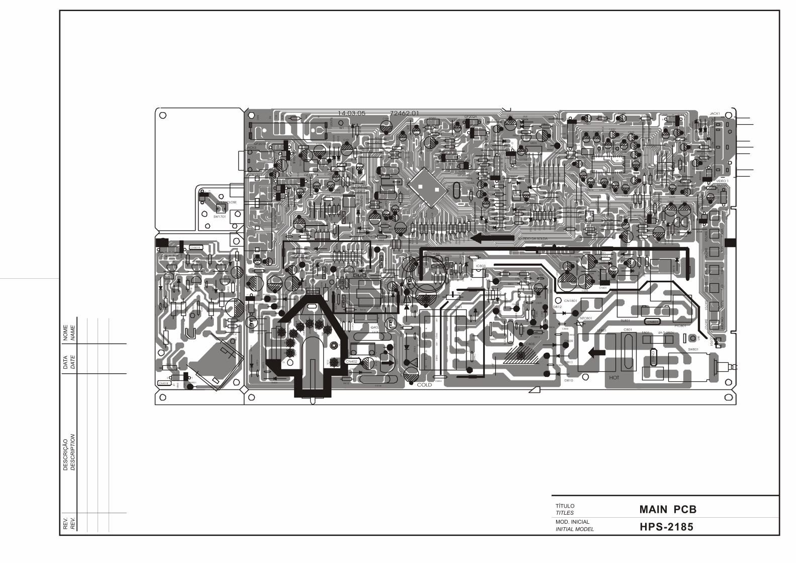
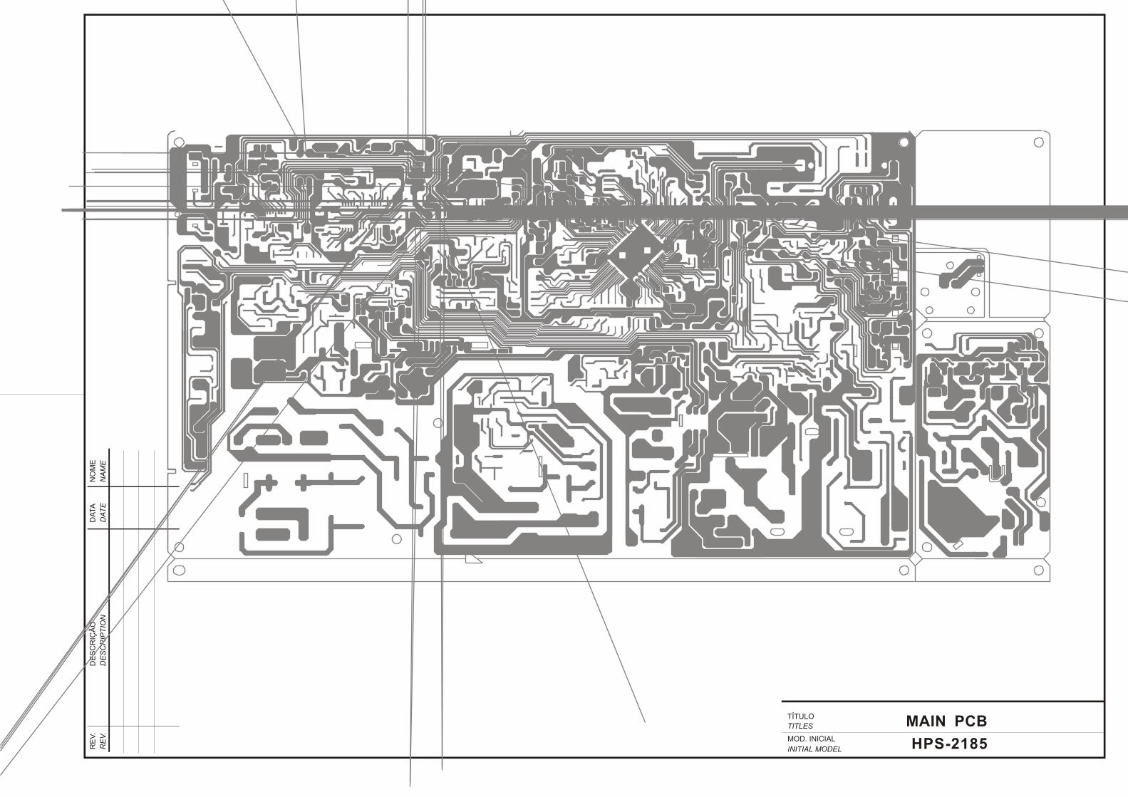
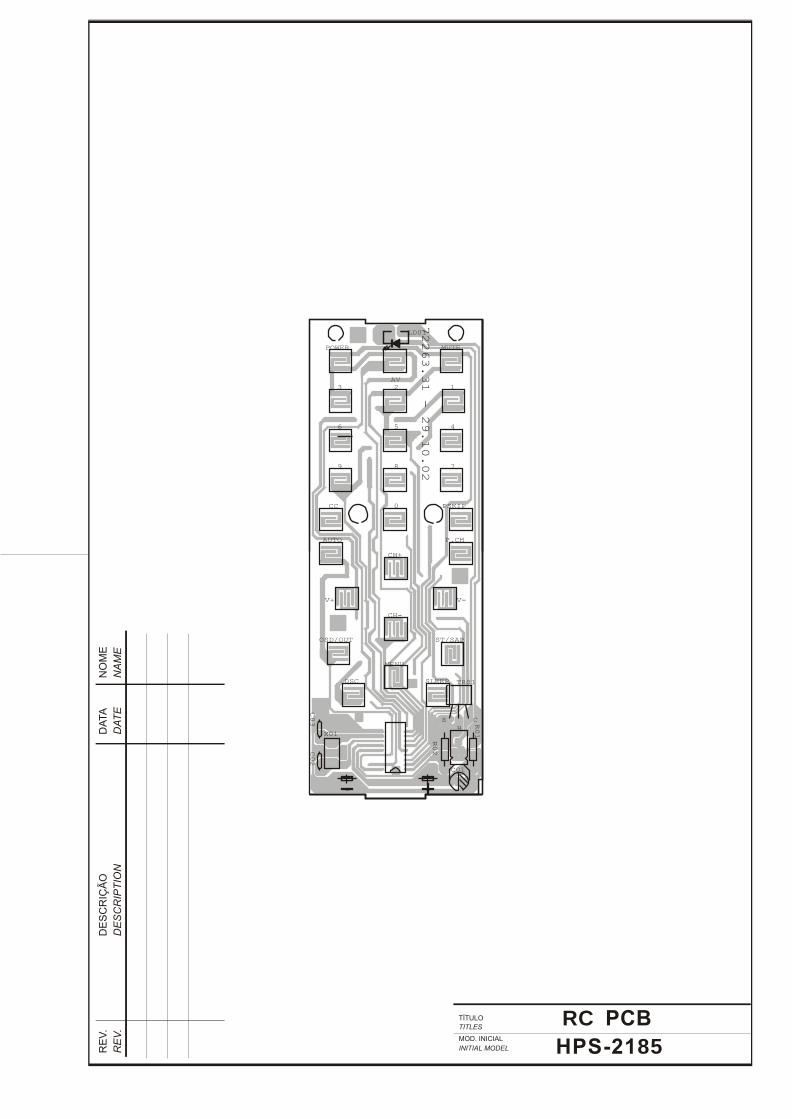
RC PCB
HPS-2185
E
B
C
LD01
X01
C01
72263.31 - 29.10.02
C02
C03
R02
R01
TR01
ST/SAP
AUTO
PSKIP
DSC
+-
MUTEPOWER
SLEEP
AV
OSD/OUT
V-V+
CH+
CH-
MENU
123
6 5 4
789
P.CH
0CC
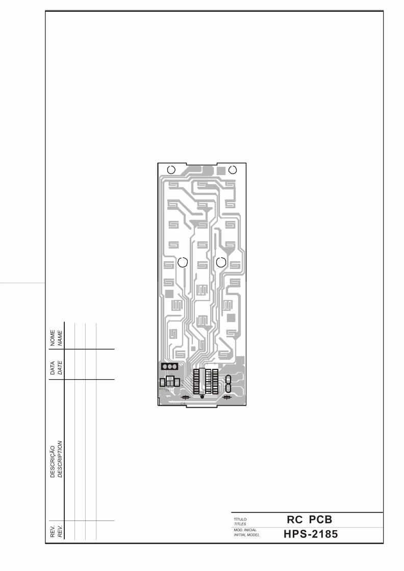
RC PCB
HPS-2185
IC01
1
10
11
20 C02R02 C03
R01TR01
C
EB
10
1
C4
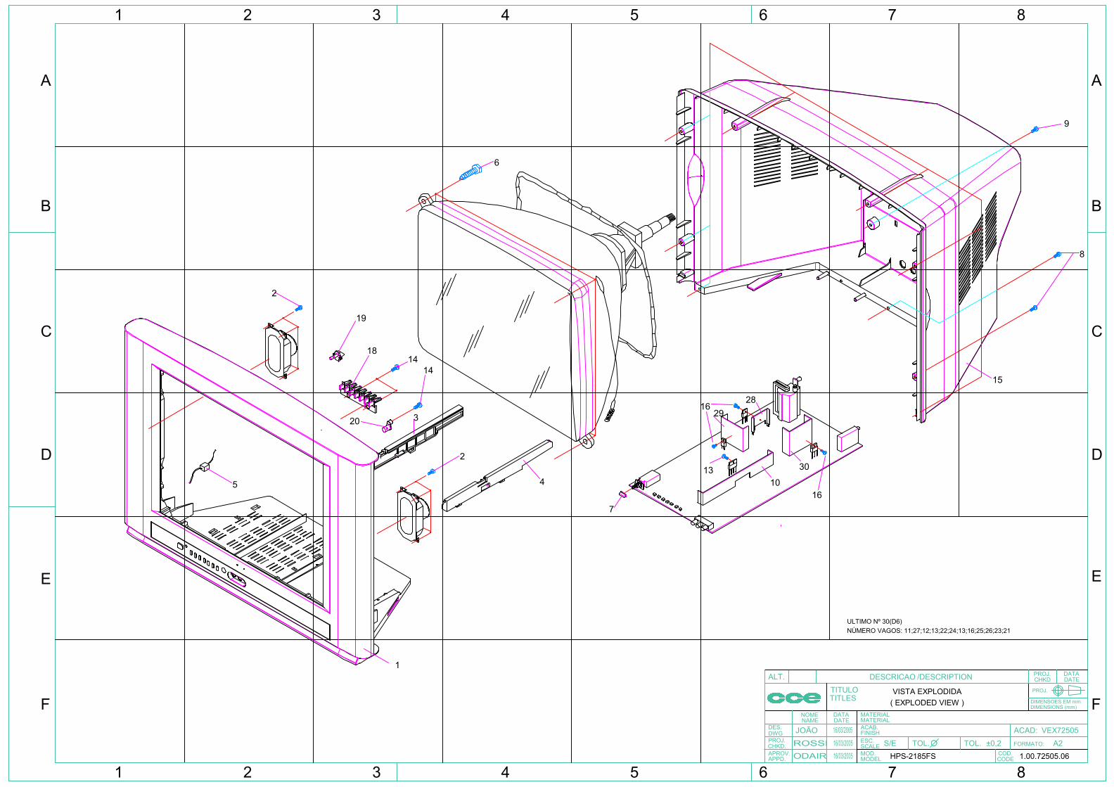
1
2
3
2
6
7
15
8
9
5
ULTIMO Nº 30(D6)
1814
19
20
14
4
1629
28
1310
30
16
87654321
A
C
D
B
E
1 2 3 4 5 6 7 8
ACAD:TOL. TOL.
PROJ.
ALT.
TITULOTITLES
DESCRICAO /DESCRIPTION PROJ. DATADATECHKD
DIMENSIONS (mm)DIMENSOES EM mm
CODECOD.
MODELMOD.SCALEESC.FINISHACAB.MATERIALMATERIAL
NAME DATEDATANOME
DWG
CHKD.
APPD.APROV.
DES.
PROJ. FORMATO:
F F
E
D
C
B
A
VISTA EXPLODIDA( EXPLODED VIEW )
S/EHPS-2185FS
±0,2 A21.00.72505.06
VEX72505 JOÃO 16/03/2005
ROSSIODAIR 16/03/2005
16/03/2005
NÚMERO VAGOS: 11;27;12;13;22;24;13;16;25;26;23;21
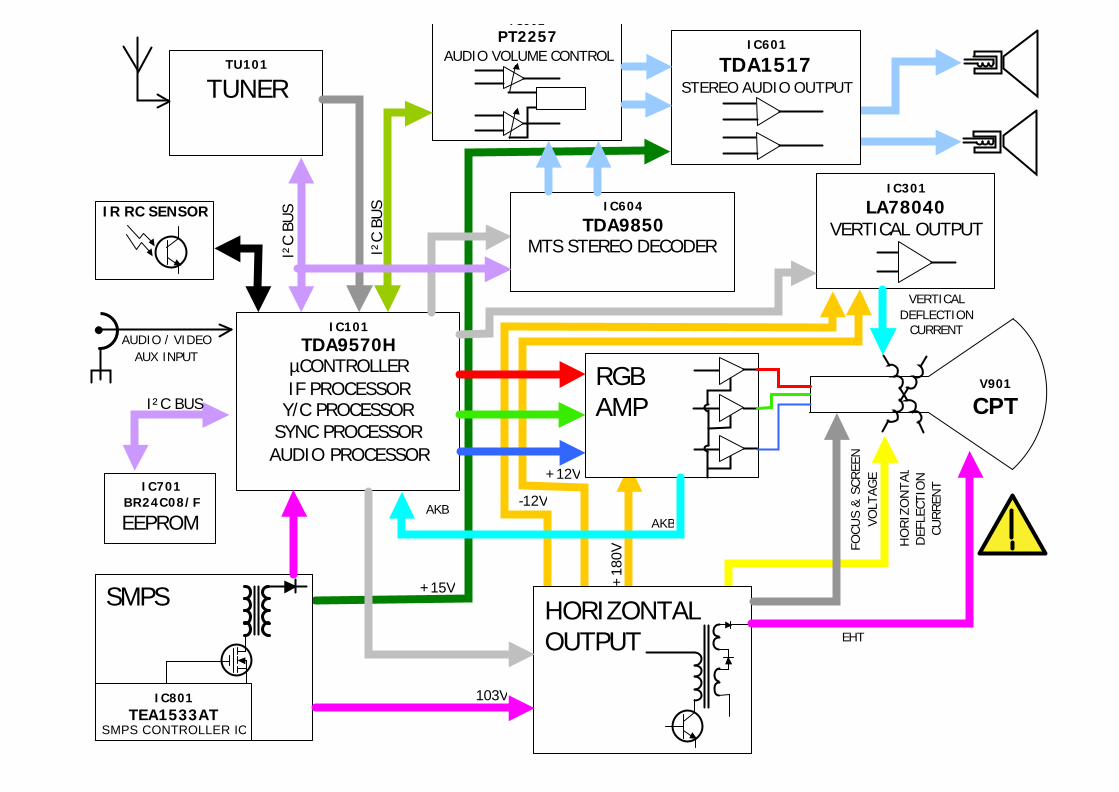
IR RC SENSOR
IC101
TDA9570H µCONTROLLER IF PROCESSOR
Y/C PROCESSOR SYNC PROCESSOR AUDIO PROCESSOR
TU101
TUNER
SMPS
AUDIO / VIDEO AUX INPUT
HORIZONTAL OUTPUT
IC301
LA78040 VERTICAL OUTPUT
RGB AMP
EHT
FOCU
S &
SCR
EEN
VO
LTAG
E
HO
RIZ
ON
TA
L D
EFLE
CTIO
N
CURREN
T
VERTICAL DEFLECTION
CURRENT
AKB
103V
+15V
+12V
AKB
+18
0V
-12V
V901
CPT
IC701 BR24C08/F
EEPROM
I²C BUS
I²C
BUS
IC601
TDA1517 STEREO AUDIO OUTPUT
IC602 PT2257
AUDIO VOLUME CONTROL
I²C
BUS
IC604
TDA9850 MTS STEREO DECODER
IC801 TEA1533AT
SMPS CONTROLLER IC


