SERVICE MANUAL - Lexmoto1. specification / tighten torque values 1-2 torque values (engine) item...
75
LJ1P37QMB(3B3) 4- STROKE 50cc SERVICE MANUAL LCJNG..JIA
Transcript of SERVICE MANUAL - Lexmoto1. specification / tighten torque values 1-2 torque values (engine) item...
LJ1P37QMB(3B3) 4- STROKE 50cc
SERVICE MANUAL
LCJNG..JIA
CONTENTS
CONTENTS
SPECIFICATION/TIGHTEN TORQUE VALVE 1
MAINTENANCE INFORMATION 2
LUBRICATION SYSTEM 3
ELECTRONICALLY CONTROLLED CARBURETOR SYSTEM 4
REMOVAL ENGINE 5
CYLINDER HEAD & VALVE 6
CYLINDER & PISTON 7
V BELT DRIVING SYSTEM / KICK START SYSTEM 8
FINAL DRIVING SYSTEM 9
ACG 10
CRNKCASE & CRANKSHAFT 11
STARTING CLUTCH 12
1. SPECIFICATION / TIGHTEN TORQUE VALUES
1-1
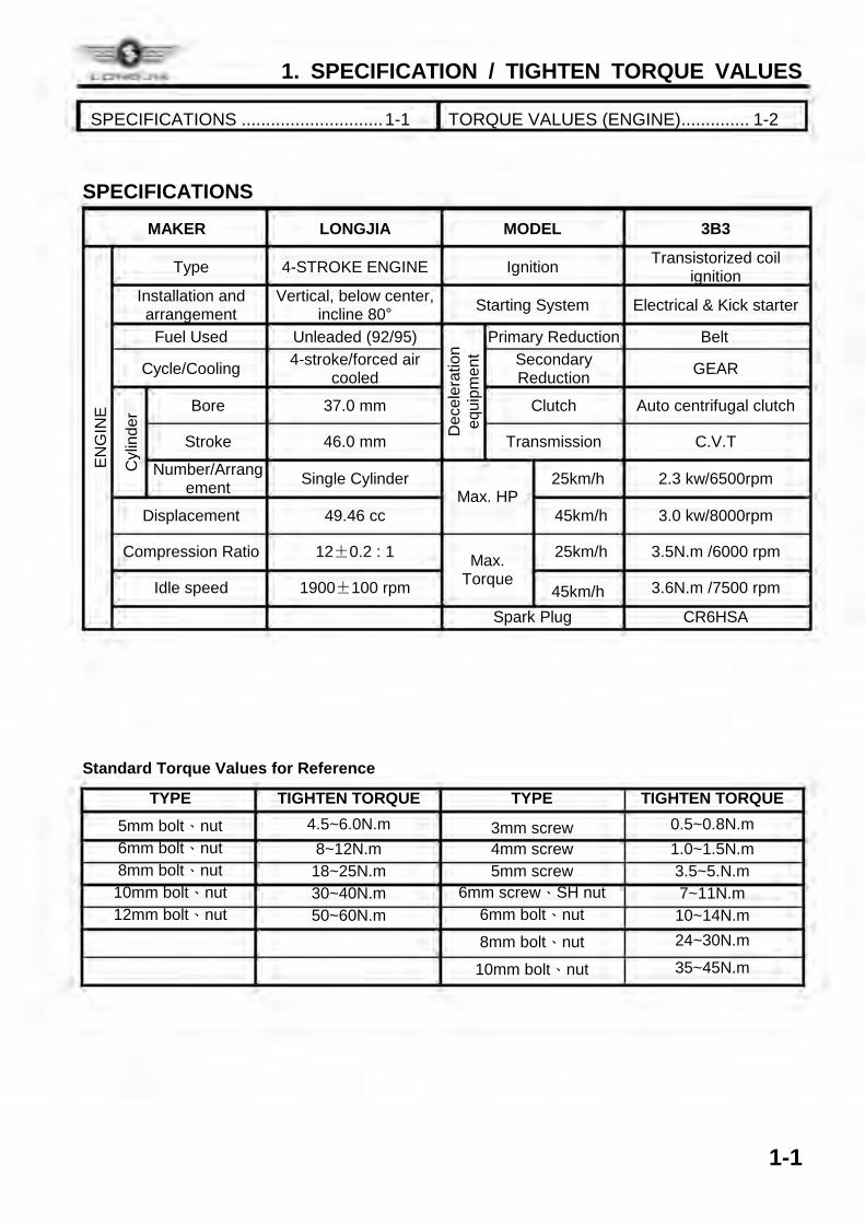
SPECIFICATIONS
MAKER LONGJIA MODEL 3B3
ENG
INE
Type 4-STROKE ENGINE Ignition Transistorized coil ignition
Installation and arrangement
Vertical, below center, incline 80° Starting System Electrical & Kick starter
Fuel Used Unleaded (92/95)
Dec
eler
atio
n eq
uipm
ent
Primary Reduction Belt
Cycle/Cooling 4-stroke/forced air cooled
Secondary Reduction GEAR
Cyl
inde
r Bore 37.0 mm Clutch Auto centrifugal clutch
Stroke 46.0 mm Transmission C.V.T
Number/Arrangement Single Cylinder
Max. HP 25km/h 2.3 kw/6500rpm
Displacement 49.46 cc 45km/h 3.0 kw/8000rpm
Compression Ratio 12±0.2 : 1 Max. Torque
25km/h 3.5N.m /6000 rpm
Idle speed 1900±100 rpm 45km/h 3.6N.m /7500 rpm
Spark Plug CR6HSA Standard Torque Values for Reference
TYPE TIGHTEN TORQUE TYPE TIGHTEN TORQUE 5mm bolt、nut 4.5~6.0N.m 3mm screw 0.5~0.8N.m 6mm bolt、nut 8~12N.m 4mm screw 1.0~1.5N.m 8mm bolt、nut 18~25N.m 5mm screw 3.5~5.N.m 10mm bolt、nut 30~40N.m 6mm screw、SH nut 7~11N.m 12mm bolt、nut 50~60N.m 6mm bolt、nut 10~14N.m
8mm bolt、nut 24~30N.m
10mm bolt、nut 35~45N.m
SPECIFICATIONS ............................. 1-1 TORQUE VALUES (ENGINE) .............. 1-2
LONO..IIA
1. SPECIFICATION / TIGHTEN TORQUE VALUES
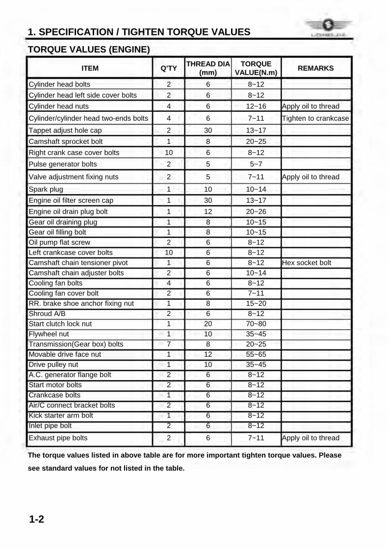
1-2
TORQUE VALUES (ENGINE)
ITEM Q'TY THREAD DIA (mm)
TORQUE VALUE(N.m) REMARKS
Cylinder head bolts 2 6 8~12 Cylinder head left side cover bolts 2 6 8~12 Cylinder head nuts 4 6 12~16 Apply oil to thread
Cylinder/cylinder head two-ends bolts 4 6 7~11 Tighten to crankcase
Tappet adjust hole cap 2 30 13~17 Camshaft sprocket bolt 1 8 20~25 Right crank case cover bolts 10 6 8~12 Pulse generator bolts 2 5 5~7
Valve adjustment fixing nuts 2 5 7~11 Apply oil to thread
Spark plug 1 10 10~14 Engine oil filter screen cap 1 30 13~17 Engine oil drain plug bolt 1 12 20~26 Gear oil draining plug 1 8 10~15 Gear oil filling bolt 1 8 10~15 Oil pump flat screw 2 6 8~12 Left crankcase cover bolts 10 6 8~12 Camshaft chain tensioner pivot 1 6 8~12 Hex socket bolt Camshaft chain adjuster bolts 2 6 10~14 Cooling fan bolts 4 6 8~12 Cooling fan cover bolt 2 6 7~11 RR. brake shoe anchor fixing nut 1 8 15~20 Shroud A/B 2 6 8~12 Start clutch lock nut 1 20 70~80 Flywheel nut 1 10 35~45 Transmission(Gear box) bolts 7 8 20~25 Movable drive face nut 1 12 55~65 Drive pulley nut 1 10 35~45 A.C. generator flange bolt 2 6 8~12 Start motor bolts 2 6 8~12 Crankcase bolts 1 6 8~12 Air/C connect bracket bolts 2 6 8~12 Kick starter arm bolt 1 6 8~12 Inlet pipe bolt 2 6 8~12
Exhaust pipe bolts 2 6 7~11 Apply oil to thread
The torque values listed in above table are for more important tighten torque values. Please
see standard values for not listed in the table.
L0..,.0 .. HA
2. MAINTENANCE INFORMATION
2-1
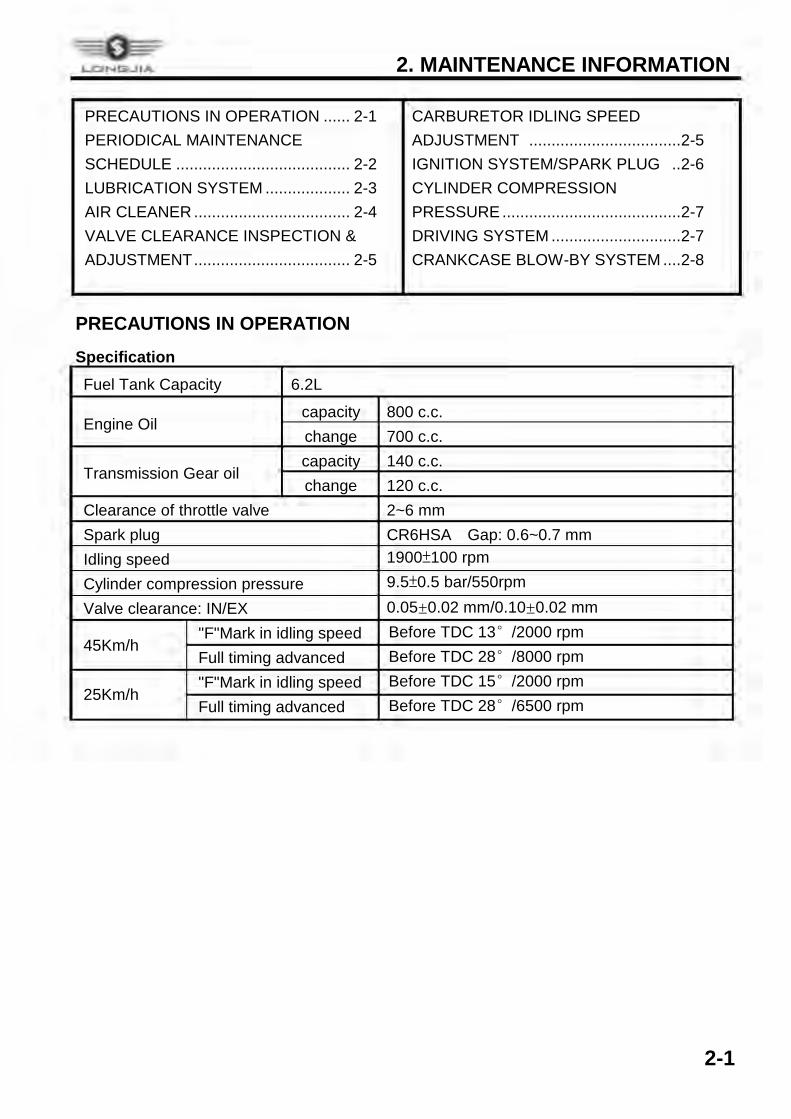
PRECAUTIONS IN OPERATION ...... 2-1 PERIODICAL MAINTENANCE SCHEDULE ....................................... 2-2 LUBRICATION SYSTEM ................... 2-3 AIR CLEANER ................................... 2-4 VALVE CLEARANCE INSPECTION & ADJUSTMENT ................................... 2-5
CARBURETOR IDLING SPEED ADJUSTMENT .................................. 2-5 IGNITION SYSTEM/SPARK PLUG .. 2-6 CYLINDER COMPRESSION PRESSURE ........................................ 2-7 DRIVING SYSTEM ............................. 2-7 CRANKCASE BLOW-BY SYSTEM .... 2-8
PRECAUTIONS IN OPERATION
Specification Fuel Tank Capacity 6.2L
Engine Oil capacity 800 c.c. change 700 c.c.
Transmission Gear oil capacity 140 c.c. change 120 c.c.
Clearance of throttle valve 2~6 mm Spark plug CR6HSA Gap: 0.6~0.7 mm Idling speed 1900±100 rpm Cylinder compression pressure 9.5±0.5 bar/550rpm Valve clearance: IN/EX 0.05±0.02 mm/0.10±0.02 mm
45Km/h "F"Mark in idling speed Before TDC 13°/2000 rpm Full timing advanced Before TDC 28°/8000 rpm
25Km/h "F"Mark in idling speed Before TDC 15°/2000 rpm Full timing advanced Before TDC 28°/6500 rpm
~e LCNl:ii_JIA
2. MAINTENANCE INFORMATION
2-2
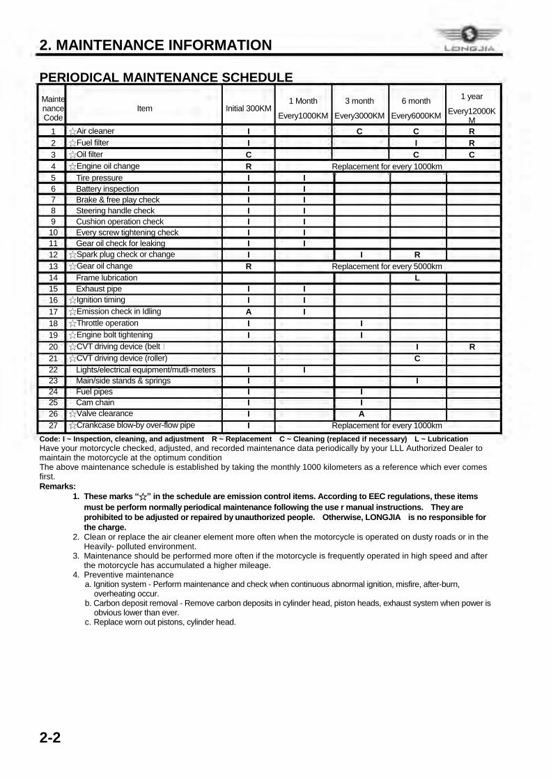
PERIODICAL MAINTENANCE SCHEDULE Maintenance Code
Item Initial 300KM 1 Month
Every1000KM
3 month
Every3000KM
6 month
Every6000KM
1 year
Every12000KM
1 ☆Air cleaner I C C R 2 ☆Fuel filter I I R 3 ☆Oil filter C C C 4 ☆Engine oil change R Replacement for every 1000km 5 Tire pressure I I 6 Battery inspection I I 7 Brake & free play check I I 8 Steering handle check I I 9 Cushion operation check I I 10 Every screw tightening check I I 11 Gear oil check for leaking I I 12 ☆Spark plug check or change I I R 13 ☆Gear oil change R Replacement for every 5000km 14 Frame lubrication L 15 Exhaust pipe I I 16 ☆Ignition timing I I 17 ☆Emission check in Idling A I 18 ☆Throttle operation I I 19 ☆Engine bolt tightening I I 20 ☆CVT driving device (belt﹞ I R 21 ☆CVT driving device (roller) C 22 Lights/electrical equipment/mutli-meters I I 23 Main/side stands & springs I I 24 Fuel pipes I I 25 Cam chain I I 26 ☆Valve clearance I A 27 ☆Crankcase blow-by over-flow pipe I Replacement for every 1000km
Code: I ~ Inspection, cleaning, and adjustment R ~ Replacement C ~ Cleaning (replaced if necessary) L ~ Lubrication Have your motorcycle checked, adjusted, and recorded maintenance data periodically by your LLL Authorized Dealer to maintain the motorcycle at the optimum condition The above maintenance schedule is established by taking the monthly 1000 kilometers as a reference which ever comes first. Remarks:
1. These marks “☆” in the schedule are emission control items. According to EEC regulations, these items must be perform normally periodical maintenance following the use r manual instructions. They are prohibited to be adjusted or repaired by unauthorized people. Otherwise, LONGJIA is no responsible for the charge.
2. Clean or replace the air cleaner element more often when the motorcycle is operated on dusty roads or in the Heavily- polluted environment.
3. Maintenance should be performed more often if the motorcycle is frequently operated in high speed and after the motorcycle has accumulated a higher mileage.
4. Preventive maintenance a. Ignition system - Perform maintenance and check when continuous abnormal ignition, misfire, after-burn,
overheating occur. b. Carbon deposit removal - Remove carbon deposits in cylinder head, piston heads, exhaust system when power is
obvious lower than ever. c. Replace worn out pistons, cylinder head.
LCNl:.-IIA
2. MAINTENANCE INFORMATION
2-3
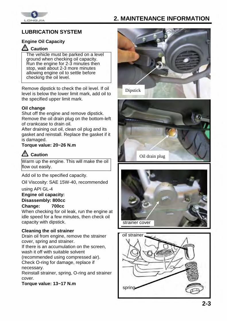
LUBRICATION SYSTEM
Engine Oil Capacity Caution
Remove dipstick to check the oil level. If oil level is below the lower limit mark, add oil to the specified upper limit mark.
Oil change Shut off the engine and remove dipstick. Remove the oil drain plug on the bottom-left of crankcase to drain oil. After draining out oil, clean oil plug and its gasket and reinstall. Replace the gasket if it is damaged. Torque value: 20~26 N.m
Caution Add oil to the specified capacity. Oil Viscosity: SAE 15W-40, recommended using API GL-4 Engine oil capacity: Disassembly: 800cc Change: 700cc When checking for oil leak, run the engine at idle speed for a few minutes, then check oil capacity with dipstick.
Cleaning the oil strainer Drain oil from engine, remove the strainer cover, spring and strainer. If there is an accumulation on the screen, wash it off with suitable solvent (recommended using compressed air). Check O-ring for damage, replace if necessary. Reinstall strainer, spring, O-ring and strainer cover. Torque value: 13~17 N.m
ü The vehicle must be parked on a level ground when checking oil capacity. ü Run the engine for 2-3 minutes then
stop, wait about 2-3 more minutes allowing engine oil to settle before checking the oil level.
Warm up the engine. This will make the oil flow out easily.
oil strainer
strainer cover
spring
Dipstick
Oil drain plug
2. MAINTENANCE INFORMATION
2-4
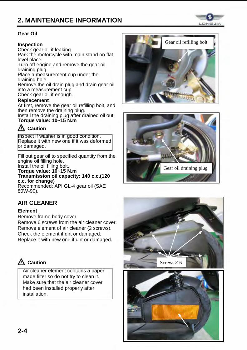
Gear Oil
Inspection Check gear oil if leaking. Park the motorcycle with main stand on flat level place. Turn off engine and remove the gear oil draining plug. Place a measurement cup under the draining hole. Remove the oil drain plug and drain gear oil into a measurement cup. Check gear oil if enough. Replacement At first, remove the gear oil refilling bolt, and then remove the draining plug. Install the draining plug after drained oil out. Torque value: 10~15 N.m
Caution Fill out gear oil to specified quantity from the engine oil filling hole. Install the oil filling bolt. Torque value: 10~15 N.m Transmission oil capacity: 140 c.c.(120 c.c. for change) Recommended: API GL-4 gear oil (SAE 80W-90).
AIR CLEANER Element Remove frame body cover. Remove 6 screws from the air cleaner cover. Remove element of air cleaner (2 screws). Check the element if dirt or damaged. Replace it with new one if dirt or damaged.
Caution
Inspect if washer is in good condition. Replace it with new one if it was deformed or damaged.
ü Air cleaner element contains a paper made filter so do not try to clean it. ü Make sure that the air cleaner cover
had been installed properly after installation.
Gear oil refilling bolt
Gear oil draining plug
Screws×6
L..CINla.llA
2. MAINTENANCE INFORMATION
2-5
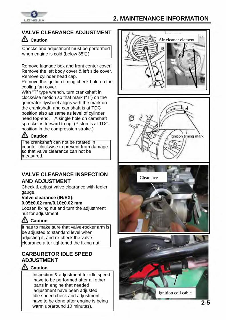
VALVE CLEARANCE ADJUSTMENT
Caution Remove luggage box and front center cover. Remove the left body cover & left side cover. Remove cylinder head cap. Remove the ignition timing check hole on the cooling fan cover. With “T” type wrench, turn crankshaft in clockwise motion so that mark (“T”) on the generator flywheel aligns with the mark on the crankshaft, and camshaft is at TDC position also as same as level of cylinder head top-end. A single hole on camshaft sprocket is forward to up. (Piston is at TDC position in the compression stroke.)
Caution
VALVE CLEARANCE INSPECTION AND ADJUSTMENT Check & adjust valve clearance with feeler gauge. Valve clearance (IN/EX): 0.05±0.02 mm/0.10±0.02 mm Loosen fixing nut and turn the adjustment nut for adjustment.
Caution CARBURETOR IDLE SPEED ADJUSTMENT
Caution
Checks and adjustment must be performed when engine is cold (below 35℃).
The crankshaft can not be rotated in counter-clockwise to prevent from damage so that valve clearance can not be measured.
It has to make sure that valve-rocker arm is be adjusted to standard level when adjusting it, and re-check the valve clearance after tightened the fixing nut.
Ignition timing mark
ü Inspection & adjustment for idle speed have to be performed after all other parts in engine that needed adjustment have been adjusted.
ü Idle speed check and adjustment have to be done after engine is being warm up(around 10 minutes).
Air cleaner element
Ignition coil cable
Clearance
LCNlli..llA
2. MAINTENANCE INFORMATION
2-6
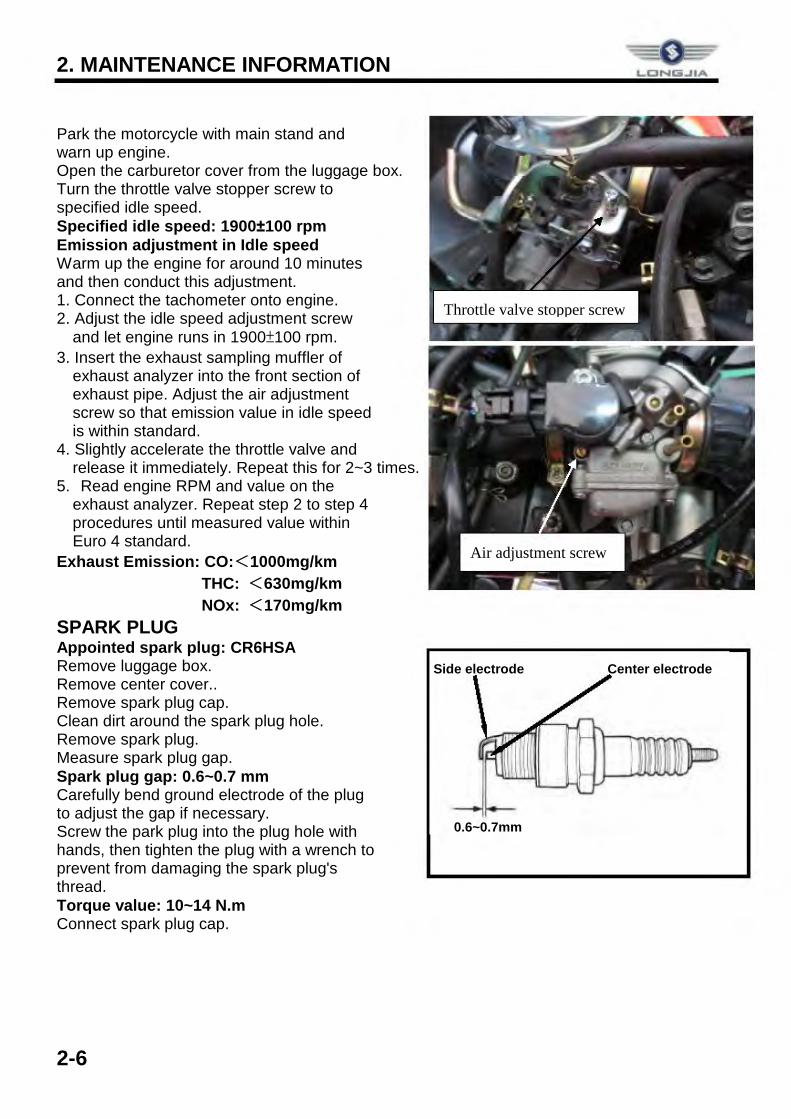
Park the motorcycle with main stand and warn up engine. Open the carburetor cover from the luggage box. Turn the throttle valve stopper screw to specified idle speed. Specified idle speed: 1900±100 rpm Emission adjustment in Idle speed Warm up the engine for around 10 minutes and then conduct this adjustment. 1. Connect the tachometer onto engine. 2. Adjust the idle speed adjustment screw
and let engine runs in 1900±100 rpm. 3. Insert the exhaust sampling muffler of
exhaust analyzer into the front section of exhaust pipe. Adjust the air adjustment screw so that emission value in idle speed is within standard.
4. Slightly accelerate the throttle valve and release it immediately. Repeat this for 2~3 times.
5. Read engine RPM and value on the exhaust analyzer. Repeat step 2 to step 4 procedures until measured value within Euro 4 standard.
Exhaust Emission: CO:<1000mg/km THC: <630mg/km NOx: <170mg/km
SPARK PLUG Appointed spark plug: CR6HSA Remove luggage box. Remove center cover.. Remove spark plug cap. Clean dirt around the spark plug hole. Remove spark plug. Measure spark plug gap. Spark plug gap: 0.6~0.7 mm Carefully bend ground electrode of the plug to adjust the gap if necessary. Screw the park plug into the plug hole with hands, then tighten the plug with a wrench to prevent from damaging the spark plug's thread. Torque value: 10~14 N.m Connect spark plug cap.
0.6~0.7mm
Side electrode Center electrode
Throttle valve stopper screw
Air adjustment screw
LCINltii..llA
2. MAINTENANCE INFORMATION
2-7
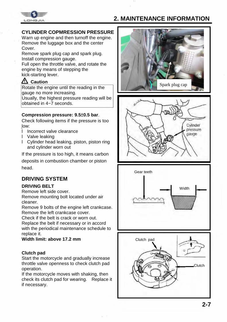
CYLINDER COPMRESSION PRESSURE Warn up engine and then turnoff the engine. Remove the luggage box and the center Cover. Remove spark plug cap and spark plug. Install compression gauge. Full open the throttle valve, and rotate the engine by means of stepping the kick-starting lever.
Caution Compression pressure: 9.5±0.5 bar. Check following items if the pressure is too low: l Incorrect valve clearance l Valve leaking l Cylinder head leaking, piston, piston ring
and cylinder worn out If the pressure is too high, it means carbon deposits in combustion chamber or piston head.
DRIVING SYSTEM DRIVING BELT Remove left side cover. Remove mounting bolt located under air cleaner. Remove 9 bolts of the engine left crankcase. Remove the left crankcase cover. Check if the belt is crack or worn out. Replace the belt if necessary or in accord with the periodical maintenance schedule to replace it. Width limit: above 17.2 mm Clutch pad Start the motorcycle and gradually increase throttle valve openness to check clutch pad operation. If the motorcycle moves with shaking, then check its clutch pad for wearing. Replace it if necessary.
Rotate the engine until the reading in the gauge no more increasing. Usually, the highest pressure reading will be obtained in 4~7 seconds.
Gear teeth
Width
Clutch
Clutch pad
Spark plug cap
2. MAINTENANCE INFORMATION
2-8
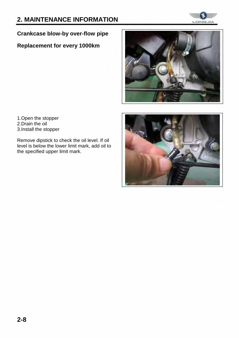
Crankcase blow-by over-flow pipe
Replacement for every 1000km 1.Open the stopper 2.Drain the oil 3.Install the stopper Remove dipstick to check the oil level. If oil level is below the lower limit mark, add oil to the specified upper limit mark.
LONG-IIA
3. LUBRICATION SYSTEM
3-1
OIL FLOW DIAGRAM ........................ 3-1 GENERAL INFORMATION ................ 3-2 TROUBLESHOOTING ....................... 3-2 ENGINE OIL ...................................... 3-3
CLEANING ENGINE OIL STRAINER ... 3-3 OIL PUMP ............................................. 3-4 GEAR OIL ............................................. 3-6
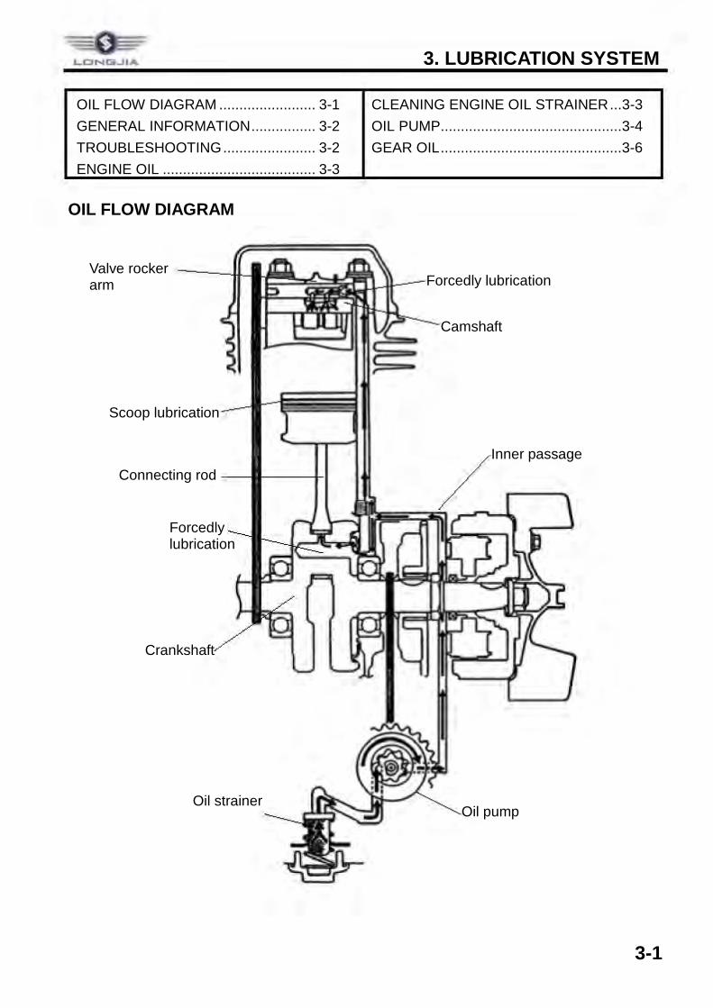
OIL FLOW DIAGRAM
Valve rocker arm
Camshaft
Scoop lubrication
Forcedly lubrication
Forcedly lubrication
Inner passage Connecting rod
Oil pump Oil strainer
Crankshaft
=-08: ¥ LCNl:ii_JIA
3. LUBRICATION SYSTEM
3-2
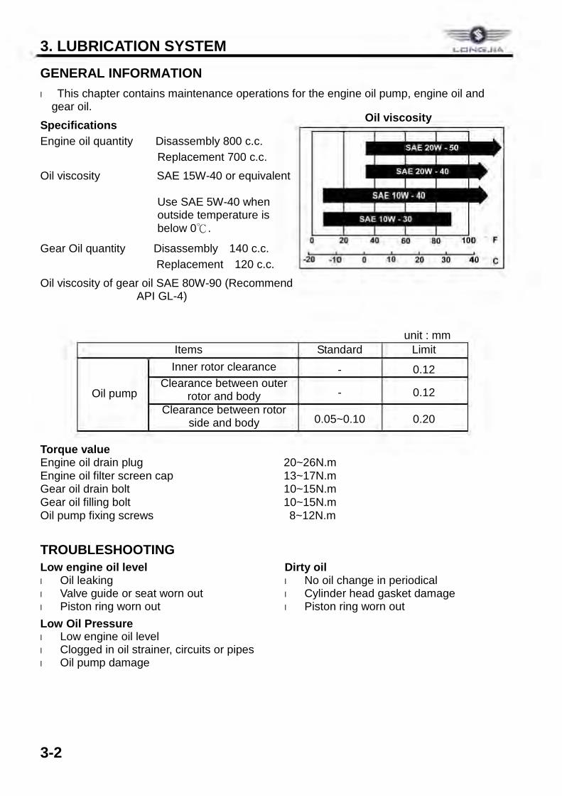
GENERAL INFORMATION l This chapter contains maintenance operations for the engine oil pump, engine oil and
gear oil. Specifications Engine oil quantity Disassembly 800 c.c.
Replacement 700 c.c. Oil viscosity SAE 15W-40 or equivalent
Use SAE 5W-40 when outside temperature is below 0℃.
Gear Oil quantity Disassembly 140 c.c. Replacement 120 c.c.
Oil viscosity of gear oil SAE 80W-90 (Recommend API GL-4)
unit : mm Items Standard Limit
Oil pump
Inner rotor clearance - 0.12 Clearance between outer
rotor and body - 0.12 Clearance between rotor
side and body 0.05~0.10 0.20 Torque value Engine oil drain plug 20~26N.m Engine oil filter screen cap 13~17N.m Gear oil drain bolt 10~15N.m Gear oil filling bolt 10~15N.m Oil pump fixing screws 8~12N.m
TROUBLESHOOTING Low engine oil level l Oil leaking l Valve guide or seat worn out l Piston ring worn out Low Oil Pressure l Low engine oil level l Clogged in oil strainer, circuits or pipes l Oil pump damage
Dirty oil l No oil change in periodical l Cylinder head gasket damage l Piston ring worn out
Oil viscosity
LCJNl:ii_JIA
0
·20 -10 0 10 20 30 40 C
3. LUBRICATION SYSTEM
3-3
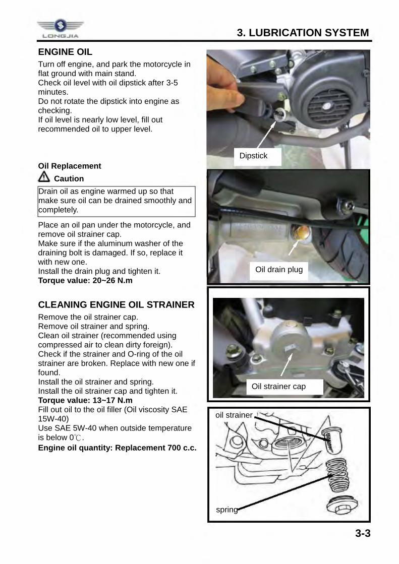
ENGINE OIL Turn off engine, and park the motorcycle in flat ground with main stand. Check oil level with oil dipstick after 3-5 minutes. Do not rotate the dipstick into engine as checking. If oil level is nearly low level, fill out recommended oil to upper level. Oil Replacement
Caution Place an oil pan under the motorcycle, and remove oil strainer cap. Make sure if the aluminum washer of the draining bolt is damaged. If so, replace it with new one. Install the drain plug and tighten it. Torque value: 20~26 N.m
CLEANING ENGINE OIL STRAINER Remove the oil strainer cap. Remove oil strainer and spring. Clean oil strainer (recommended using compressed air to clean dirty foreign). Check if the strainer and O-ring of the oil strainer are broken. Replace with new one if found. Install the oil strainer and spring. Install the oil strainer cap and tighten it. Torque value: 13~17 N.m Fill out oil to the oil filler (Oil viscosity SAE 15W-40) Use SAE 5W-40 when outside temperature is below 0℃. Engine oil quantity: Replacement 700 c.c.
Drain oil as engine warmed up so that make sure oil can be drained smoothly and completely.
oil strainer
spring
Dipstick
Oil drain plug
Oil strainer cap
LCJNGi..JIA
3. LUBRICATION SYSTEM
3-4
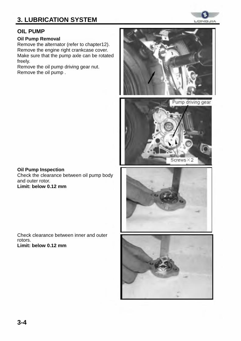
OIL PUMP Oil Pump Removal Remove the alternator (refer to chapter12). Remove the engine right crankcase cover. Make sure that the pump axle can be rotated freely. Remove the oil pump driving gear nut. Remove the oil pump .
Oil Pump Inspection Check the clearance between oil pump body and outer rotor. Limit: below 0.12 mm Check clearance between inner and outer rotors. Limit: below 0.12 mm
-
3. LUBRICATION SYSTEM
3-5
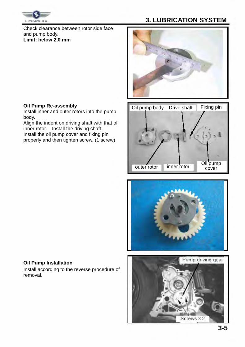
Check clearance between rotor side face and pump body. Limit: below 2.0 mm Oil Pump Re-assembly Install inner and outer rotors into the pump body. Align the indent on driving shaft with that of inner rotor. Install the driving shaft. Install the oil pump cover and fixing pin properly and then tighten screw. (1 screw)
Oil Pump Installation Install according to the reverse procedure of removal.
outer rotor inner rotor
Oil pump body
Oil pump cover
Drive shaft Fixing pin
--=""~ LCNl:ii_JIA
3. LUBRICATION SYSTEM
3-6
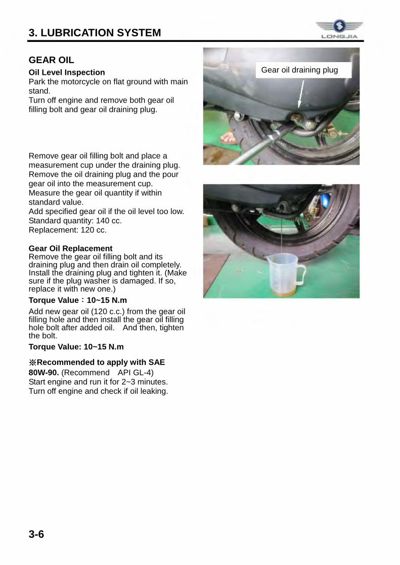
GEAR OIL Oil Level Inspection Park the motorcycle on flat ground with main stand. Turn off engine and remove both gear oil filling bolt and gear oil draining plug. Remove gear oil filling bolt and place a measurement cup under the draining plug. Remove the oil draining plug and the pour gear oil into the measurement cup. Measure the gear oil quantity if within standard value. Add specified gear oil if the oil level too low. Standard quantity: 140 cc. Replacement: 120 cc. Gear Oil Replacement Remove the gear oil filling bolt and its draining plug and then drain oil completely. Install the draining plug and tighten it. (Make sure if the plug washer is damaged. If so, replace it with new one.) Torque Value:10~15 N.m Add new gear oil (120 c.c.) from the gear oil filling hole and then install the gear oil filling hole bolt after added oil. And then, tighten the bolt. Torque Value: 10~15 N.m
※Recommended to apply with SAE 80W-90. (Recommend API GL-4) Start engine and run it for 2~3 minutes. Turn off engine and check if oil leaking.
Gear oil draining plug
0 LONm:..JtA
4. ELECTRONICALLY CONTROLLED CARBURETOR SYSTEM
4-1
ECS illustration ................................... 4-1 Precautions in operation ................... 4-2
General Information .......................... 4-3
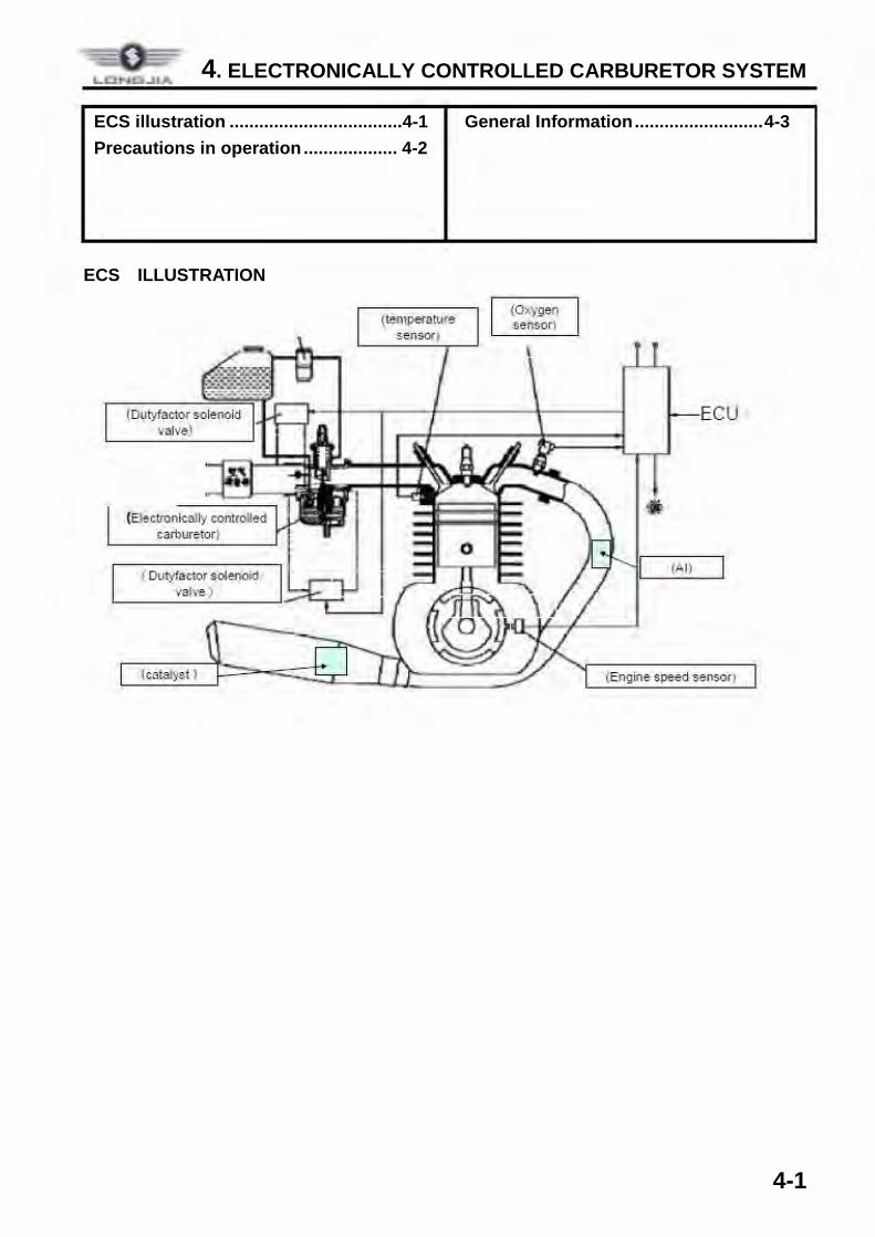
ECS ILLUSTRATION
-= LDNa.J_LA
(Bectronically controlled c.arbure·tor)
t Dutyfactor solenoid valve)
(catalyst )
(Oxygen sensor)
ECU
(Al)
(Engine. $peed sensor)
4.ELECTRONICALLY CONTROLLED CARBURETOR SYSTEM
4-2
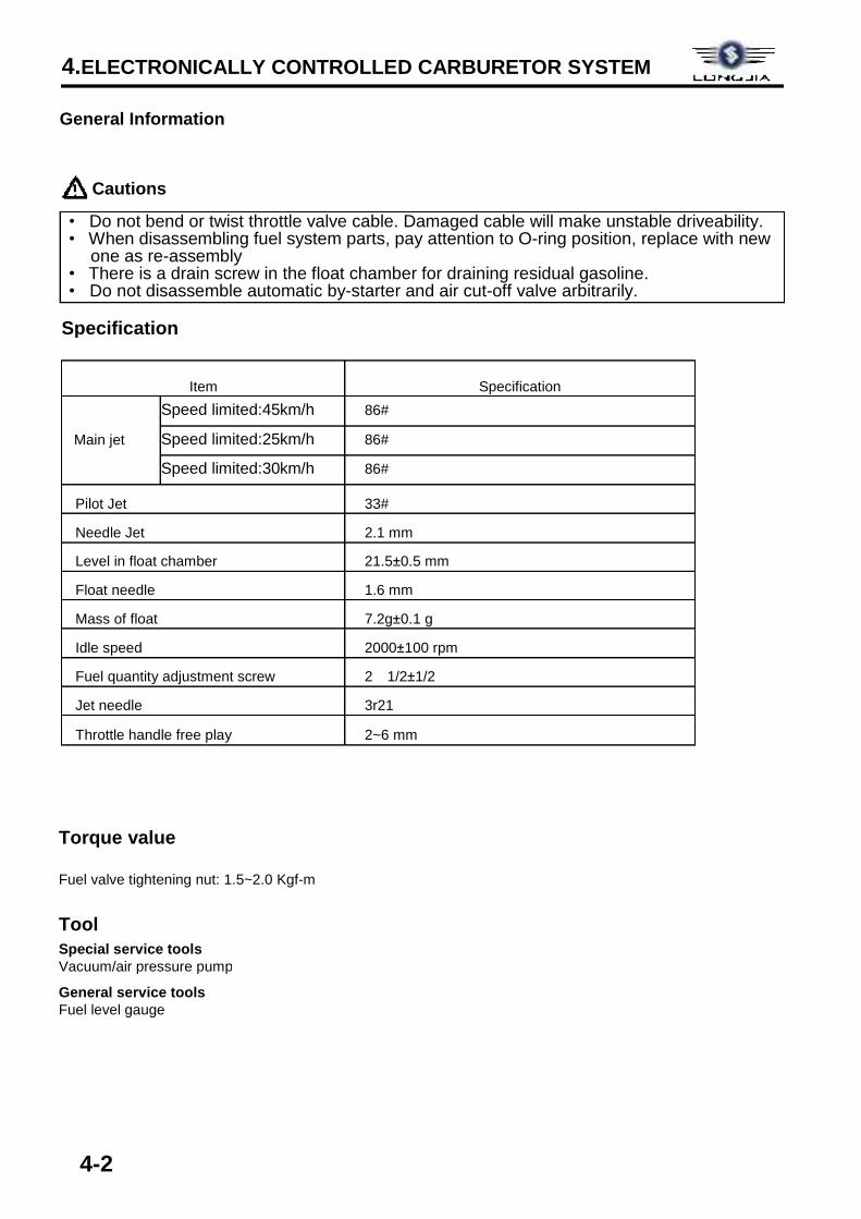
Item Specification
Main jet
Speed limited:45km/h 86#
Speed limited:25km/h 86#
Speed limited:30km/h 86#
Pilot Jet 33#
Needle Jet 2.1 mm
Level in float chamber 21.5±0.5 mm
Float needle 1.6 mm
Mass of float 7.2g±0.1 g
Idle speed 2000±100 rpm
Fuel quantity adjustment screw 2 1/2±1/2
Jet needle 3r21
Throttle handle free play 2~6 mm
Cautions
General Information
• Do not bend or twist throttle valve cable. Damaged cable will make unstable driveability. • When disassembling fuel system parts, pay attention to O-ring position, replace with new
one as re-assembly • There is a drain screw in the float chamber for draining residual gasoline. • Do not disassemble automatic by-starter and air cut-off valve arbitrarily.
Specification
Torque value
Fuel valve tightening nut: 1.5~2.0 Kgf-m
Tool Special service tools Vacuum/air pressure pump
General service tools Fuel level gauge
4. ELECTRONICALLY CONTROLLED CARBURETOR SYSTEM
4-3
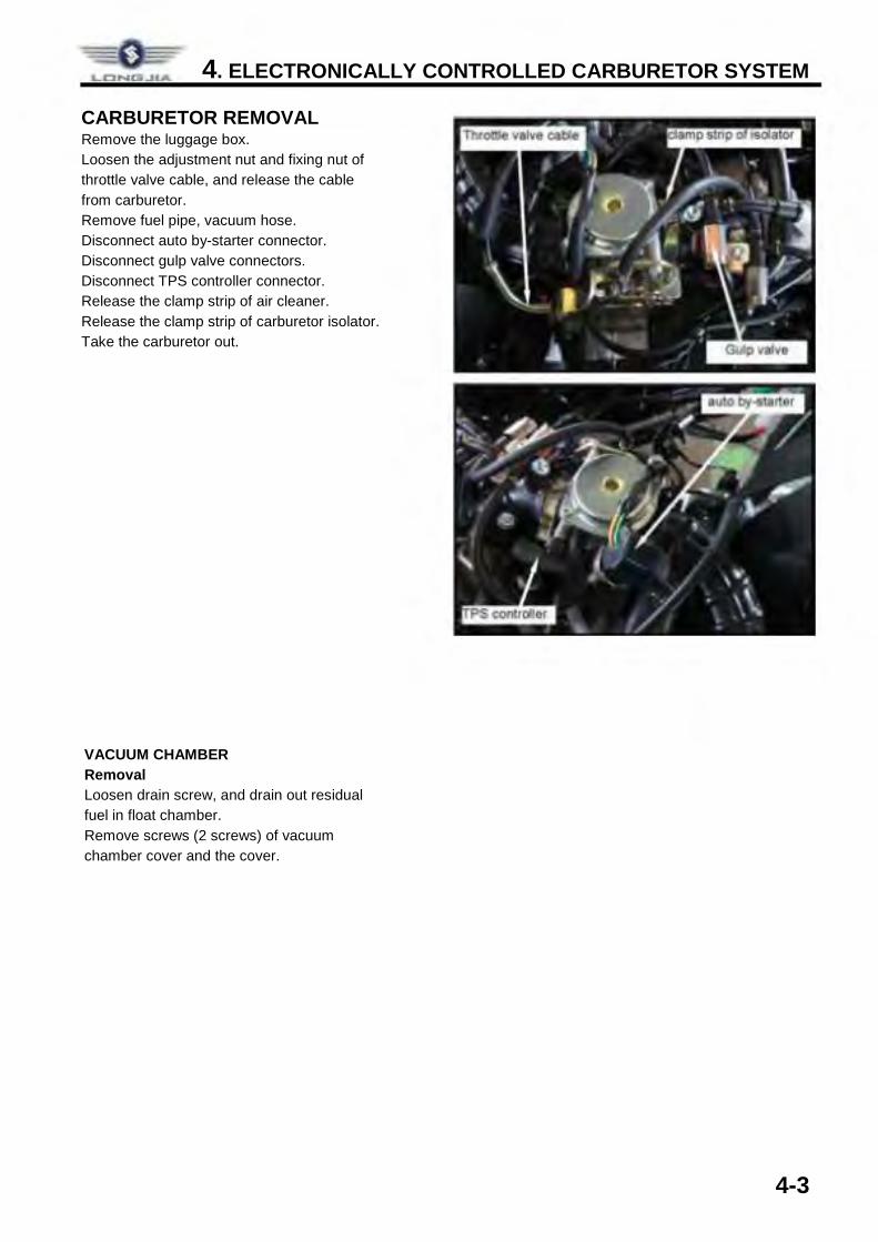
CARBURETOR REMOVAL Remove the luggage box. Loosen the adjustment nut and fixing nut of throttle valve cable, and release the cable from carburetor. Remove fuel pipe, vacuum hose. Disconnect auto by-starter connector. Disconnect gulp valve connectors. Disconnect TPS controller connector. Release the clamp strip of air cleaner. Release the clamp strip of carburetor isolator. Take the carburetor out.
VACUUM CHAMBER Removal Loosen drain screw, and drain out residual fuel in float chamber. Remove screws (2 screws) of vacuum chamber cover and the cover.
LCINl'!S.JIA
5. REMOVAL OF ENGINE
MECHANISM DIAGRAM ...................... 5-1 OPERATIONAL PRECAUTIONS ......... 5-2
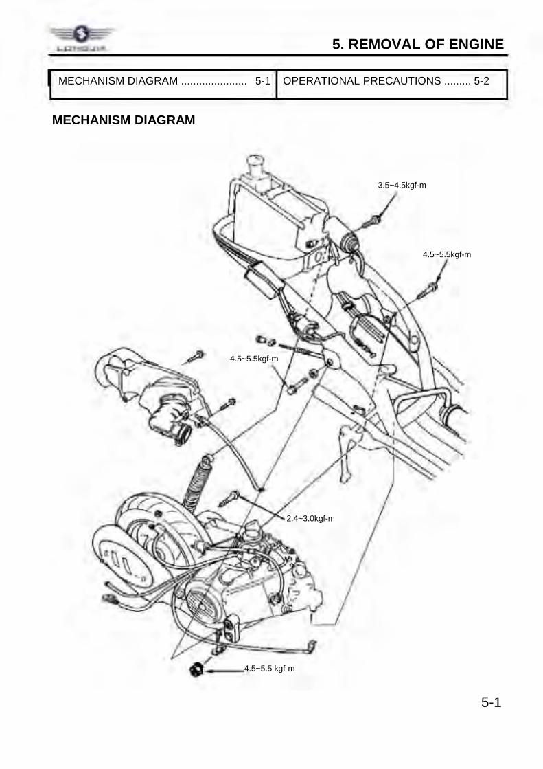
MECHANISM DIAGRAM
3.5~4.5kgf-m
4.5~5.5kgf-m
4.5~5.5kgf-m
2.4~3.0kgf-m
4.5~5.5 kgf-m 5-1
--==11 o,/ __ _
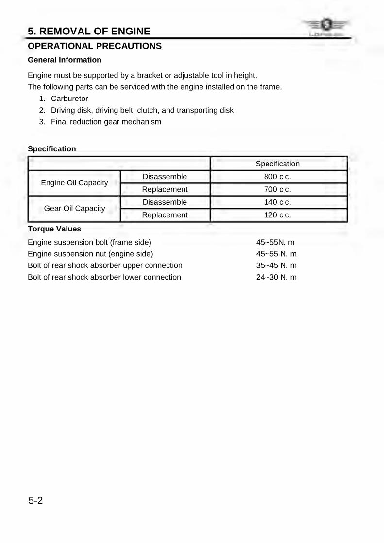
5. REMOVAL OF ENGINE OPERATIONAL PRECAUTIONS General Information Engine must be supported by a bracket or adjustable tool in height. The following parts can be serviced with the engine installed on the frame.
1. Carburetor 2. Driving disk, driving belt, clutch, and transporting disk 3. Final reduction gear mechanism
Specification Specification
Engine Oil Capacity
Disassemble 800 c.c.
Replacement 700 c.c.
Gear Oil Capacity
Disassemble 140 c.c.
Replacement 120 c.c.
Torque Values
Engine suspension bolt (frame side) 45~55N. m
Engine suspension nut (engine side) 45~55 N. m
Bolt of rear shock absorber upper connection 35~45 N. m
Bolt of rear shock absorber lower connection 24~30 N. m
5-2
6. CYLINDER HEAD / VALVE
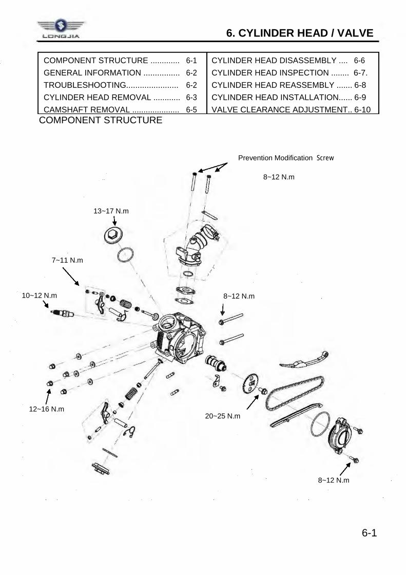
COMPONENT STRUCTURE ............. 6-1 CYLINDER HEAD DISASSEMBLY .... 6-6 GENERAL INFORMATION ................ 6-2 CYLINDER HEAD INSPECTION ........ 6-7. TROUBLESHOOTING....................... 6-2 CYLINDER HEAD REASSEMBLY ....... 6-8 CYLINDER HEAD REMOVAL ............ 6-3 CYLINDER HEAD INSTALLATION...... 6-9 CAMSHAFT REMOVAL ..................... 6-5 VALVE CLEARANCE ADJUSTMENT.. 6-10 COMPONENT STRUCTURE
6-1
8~12 N.m
8~12 N.m
13~17 N.m
10~12 N.m 8~12 N.m
12~16 N.m
7~11 N.m
Prevention Modification Screw
20~25 N.m
LCi~.JlA
~
U D I
'
• @ Q
- ~
-~~--r r . '
I _.-
1 I I r /
' (I) ' ' - ," •! -1 - ~
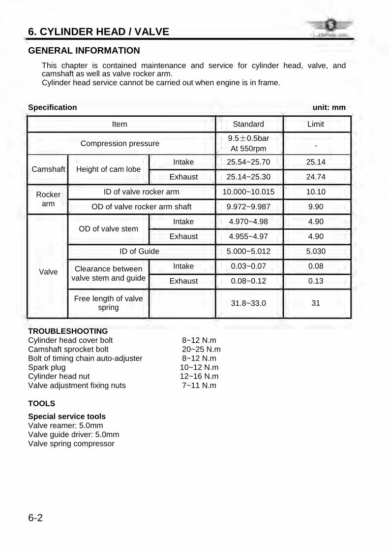
6. CYLINDER HEAD / VALVE GENERAL INFORMATION ü This chapter is contained maintenance and service for cylinder head, valve, and
camshaft as well as valve rocker arm. ü Cylinder head service cannot be carried out when engine is in frame. Specification unit: mm
Item Standard Limit
Compression pressure 9.5±0.5bar -
At 550rpm
Camshaft Height of cam lobe Intake 25.54~25.70 25.14
Exhaust 25.14~25.30 24.74
Rocker ID of valve rocker arm 10.000~10.015 10.10
arm OD of valve rocker arm shaft 9.972~9.987 9.90
OD of valve stem
Intake 4.970~4.98 4.90
Exhaust 4.955~4.97 4.90
ID of Guide 5.000~5.012 5.030
Valve Clearance between Intake 0.03~0.07 0.08
valve stem and guide
Exhaust 0.08~0.12 0.13
Free length of valve
31.8~33.0 31
spring
TROUBLESHOOTING
Cylinder head cover bolt 8~12 N.m
Camshaft sprocket bolt 20~25 N.m
Bolt of timing chain auto-adjuster 8~12 N.m
Spark plug 10~12 N.m
Cylinder head nut 12~16 N.m
Valve adjustment fixing nuts 7~11 N.m
TOOLS Special service tools Valve reamer: 5.0mm Valve guide driver: 5.0mm Valve spring compressor 6-2
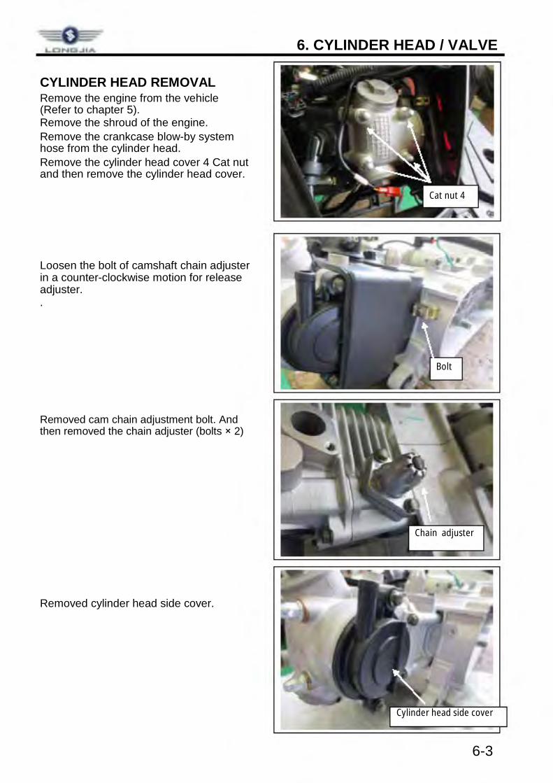
6. CYLINDER HEAD / VALVE CYLINDER HEAD REMOVAL Remove the engine from the vehicle (Refer to chapter 5). Remove the shroud of the engine. Remove the crankcase blow-by system hose from the cylinder head. Remove the cylinder head cover 4 Cat nut and then remove the cylinder head cover. Loosen the bolt of camshaft chain adjuster in a counter-clockwise motion for release adjuster. . Removed cam chain adjustment bolt. And then removed the chain adjuster (bolts × 2) Removed cylinder head side cover.
6-3
Cat nut 4
Bolt
Chain adjuster
Cylinder head side cover
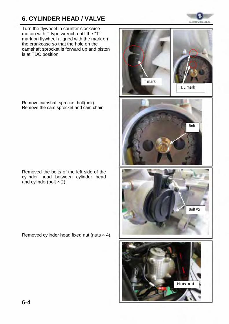
6. CYLINDER HEAD / VALVE Turn the flywheel in counter-clockwise motion with T type wrench until the “T” mark on flywheel aligned with the mark on the crankcase so that the hole on the camshaft sprocket is forward up and piston is at TDC position. Remove camshaft sprocket bolt(bolt). Remove the cam sprocket and cam chain. Removed the bolts of the left side of the cylinder head between cylinder head and cylinder(bolt × 2). Removed cylinder head fixed nut (nuts × 4).
6-4
T mark TDC mark
Bolt
Bolt×2
Nuts × 4
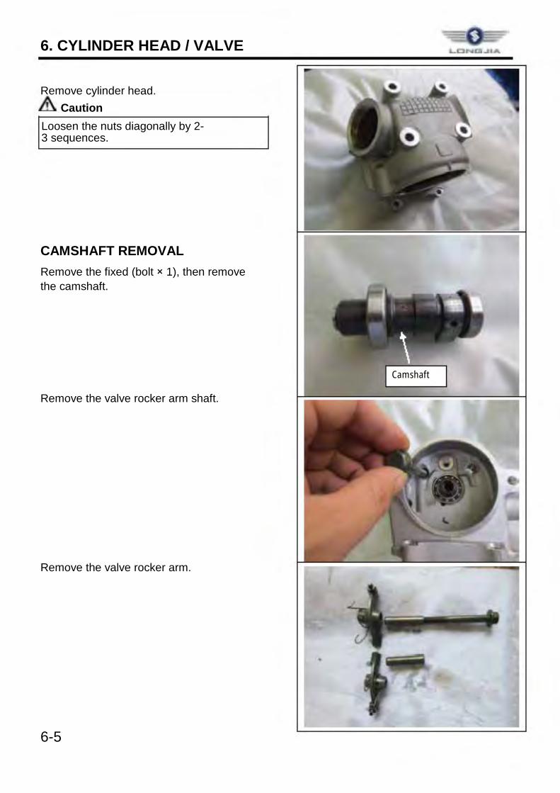
6. CYLINDER HEAD / VALVE Remove cylinder head.
Caution Loosen the nuts diagonally by 2-3 sequences. CAMSHAFT REMOVAL Remove the fixed (bolt × 1), then remove the camshaft. Remove the valve rocker arm shaft. Remove the valve rocker arm. 6-5
Camshaft
LONOIJ.lA
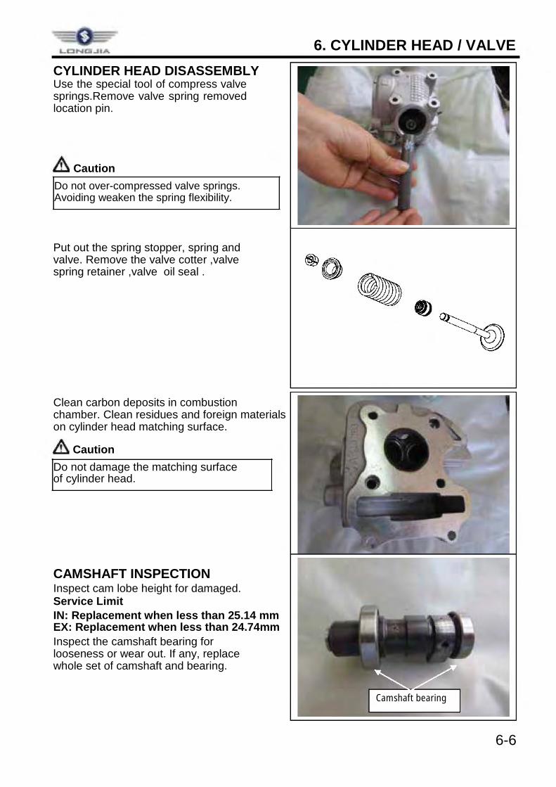
6. CYLINDER HEAD / VALVE CYLINDER HEAD DISASSEMBLY Use the special tool of compress valve springs.Remove valve spring removed location pin.
Caution Do not over-compressed valve springs. Avoiding weaken the spring flexibility. Put out the spring stopper, spring and valve. Remove the valve cotter ,valve spring retainer ,valve oil seal . Clean carbon deposits in combustion chamber. Clean residues and foreign materials on cylinder head matching surface.
Caution Do not damage the matching surface of cylinder head. CAMSHAFT INSPECTION Inspect cam lobe height for damaged. Service Limit IN: Replacement when less than 25.14 mm EX: Replacement when less than 24.74mm Inspect the camshaft bearing for looseness or wear out. If any, replace whole set of camshaft and bearing.
6-6
Camshaft bearing
I __
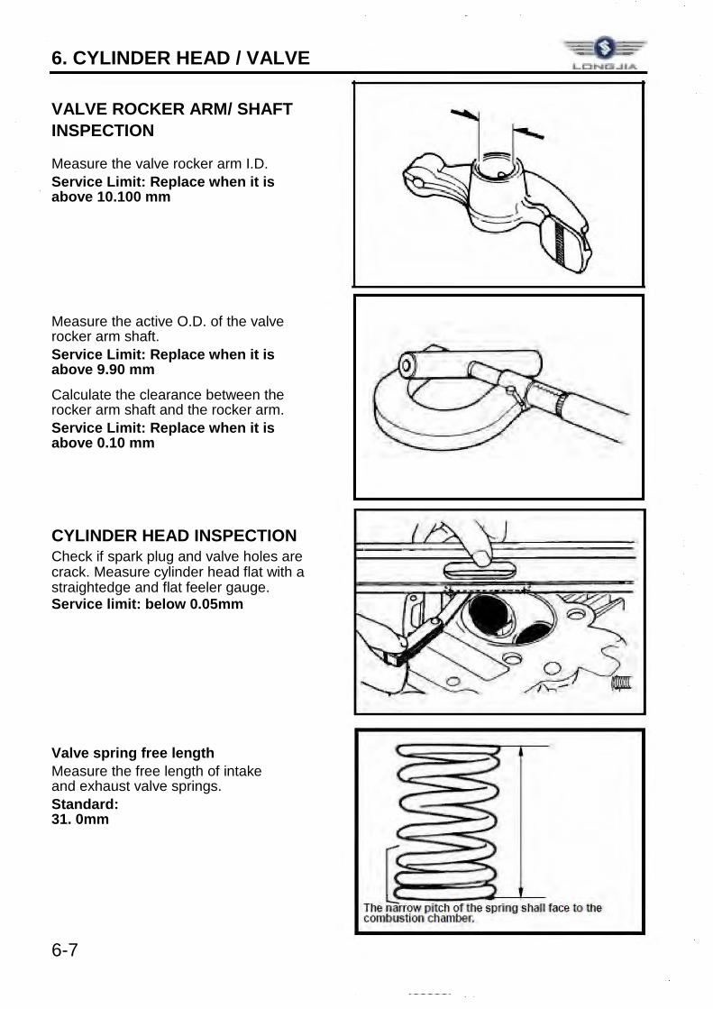
6. CYLINDER HEAD / VALVE VALVE ROCKER ARM/ SHAFT INSPECTION Measure the valve rocker arm I.D. Service Limit: Replace when it is above 10.100 mm Measure the active O.D. of the valve rocker arm shaft. Service Limit: Replace when it is above 9.90 mm Calculate the clearance between the rocker arm shaft and the rocker arm. Service Limit: Replace when it is above 0.10 mm CYLINDER HEAD INSPECTION Check if spark plug and valve holes are crack. Measure cylinder head flat with a straightedge and flat feeler gauge. Service limit: below 0.05mm Valve spring free length Measure the free length of intake and exhaust valve springs. Standard:31. 0mm 6-7
The ~rrow pitch of the sprtng shaR face lo lhe combustion chamber.
6. CYLINDER HEAD / VALVE Valve stem Check if valve stems are bend, crack or burn. Check the operation condition of valve stem in valve guide, and measure & record the valve stem outer diameter. Service Limit: IN→ 4.900mm
EX→ 4.900mm Valve guide
Caution
Before measuring the valve guide, clean carbon deposits with reamer.
Special Service Tool: 5.0mm valve guide reamer Measure and record each valve guide inner diameters. Service limit: 5.030mm The difference that the inner diameter of valve guide deducts the outer diameter of valve stem is the clearance between the valve stem and valve guide. Service Limit: IN→ 0.13mm
EX→ 0.13mm
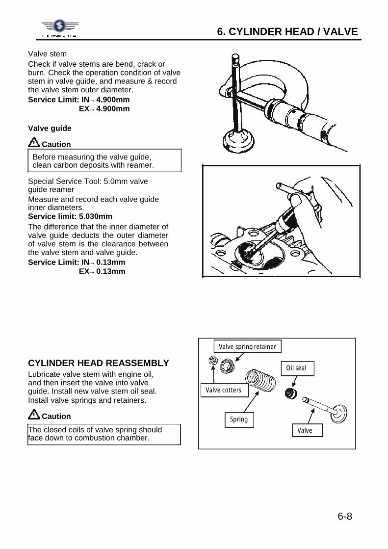
CYLINDER HEAD REASSEMBLY Lubricate valve stem with engine oil, and then insert the valve into valve guide. Install new valve stem oil seal. Install valve springs and retainers.
Caution The closed coils of valve spring should face down to combustion chamber.
6-8
Valve cotters
Valve spring retainer
Spring
Oil seal
Valve
I I @, o/ /Q'/?J.\\"""'- y
A ~ L_I ____ I L__ __ _
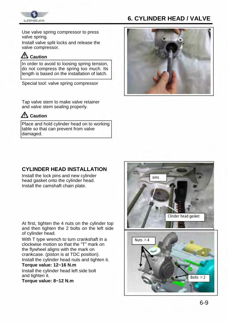
6. CYLINDER HEAD / VALVE Use valve spring compressor to press valve spring. Install valve split locks and release the valve compressor.
Caution In order to avoid to loosing spring tension, do not compress the spring too much. Its length is based on the installation of latch. Special tool: valve spring compressor Tap valve stem to make valve retainer and valve stem sealing properly.
Caution Place and hold cylinder head on to working table so that can prevent from valve damaged. CYLINDER HEAD INSTALLATION Install the lock pins and new cylinder head gasket onto the cylinder head. Install the camshaft chain plate. At first, tighten the 4 nuts on the cylinder top and then tighten the 2 bolts on the left side of cylinder head. With T type wrench to turn crankshaft in a clockwise motion so that the “T” mark on the flywheel aligns with the mark on crankcase. (piston is at TDC position). Install the cylinder head nuts and tighten it. Torque value: 12~16 N.m Install the cylinder head left side bolt and tighten it. Torque value: 8~12 N.m
6-9
Clinder head gasket
pins
Nuts ×4
Bolts ×2
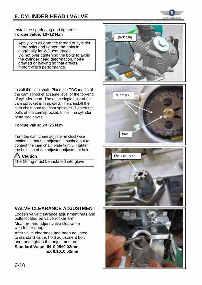
6. CYLINDER HEAD / VALVE Install the spark plug and tighten it. Torque value: 10~12 N.m
Apply with oil onto the thread of cylinder head bolts and tighten the bolts in diagonally for 2-3 sequences. Do not over tightening the bolts to avoid the cylinder head deformation, noise created or leaking so that effects motorcycle’s performance.
Install the cam shaft. Place the TDC marks of the cam sprocket at same level of the top-end of cylinder head. The other single hole of the cam sprocket is in upward. Then, install the cam chain onto the cam sprocket. Tighten the bolts of the cam sprocket. Install the cylinder head side cover. Torque value: 20~25 N.m Turn the cam chain adjuster in clockwise motion so that the adjuster is pushed out to contact the cam chain plate tightly. Tighten the bolt cap of the adjuster adjustment hole.
Caution The O-ring must be installed into glove. VALVE CLEARANCE ADJUSTMENT Loosen valve clearance adjustment nuts and bolts located on valve rocker arm. Measure and adjust valve clearance with feeler gauge. After valve clearance had been adjusted to standard value, hold adjustment bolt and then tighten the adjustment nut. Standard Value: IN 0.05±0.02mm EX 0.10±0.02mm
6-10
Spark plug
"T " mark
Bolt
Chain adjuster
LONl:l..llA
7. CYLINDER/PISTON
7-1
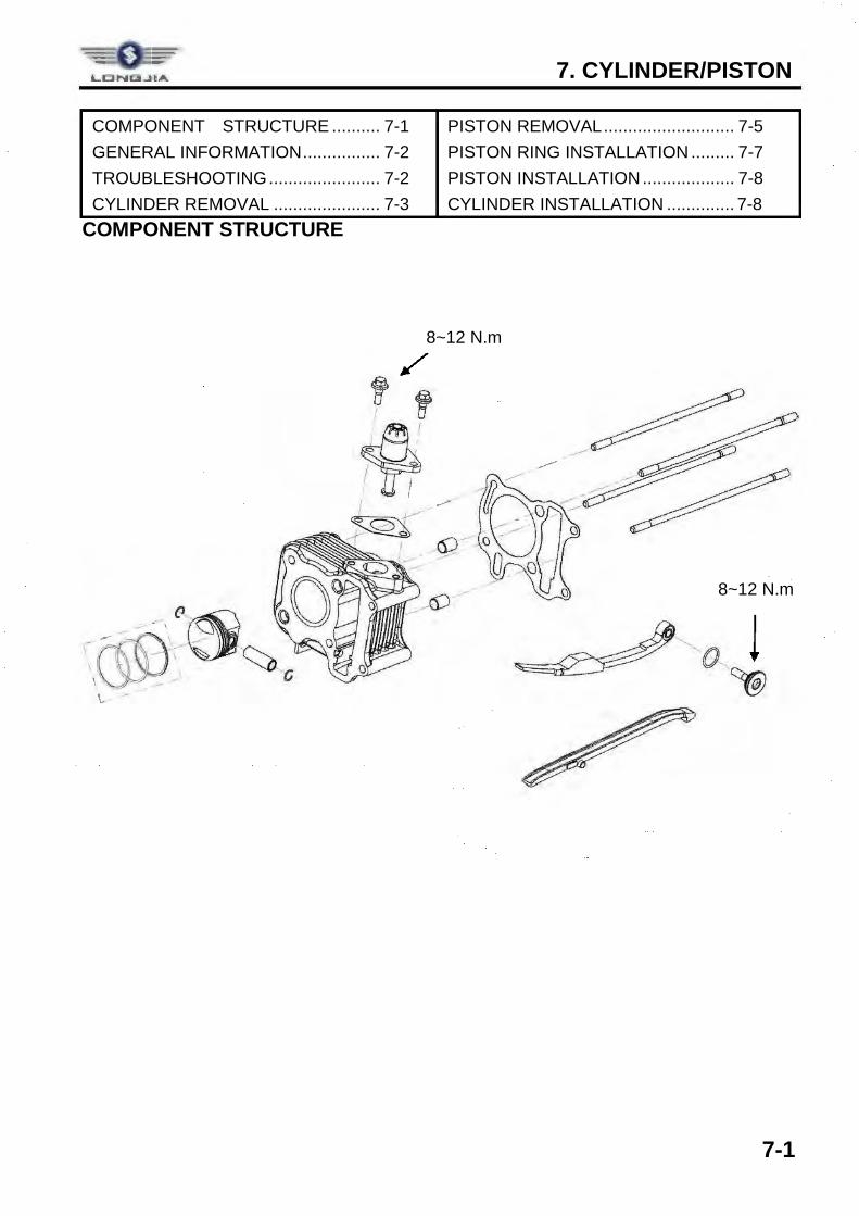
COMPONENT STRUCTURE .......... 7-1 GENERAL INFORMATION ................ 7-2 TROUBLESHOOTING ....................... 7-2 CYLINDER REMOVAL ...................... 7-3
PISTON REMOVAL ........................... 7-5 PISTON RING INSTALLATION ......... 7-7 PISTON INSTALLATION ................... 7-8 CYLINDER INSTALLATION .............. 7-8
COMPONENT STRUCTURE
8~12 N.m
8~12 N.m
LClNICJI..J IA
I -,
L -
~~ <:,::.C>...~----------~~ ---- " o l ~
7. CYLINDER/PISTON
7-2
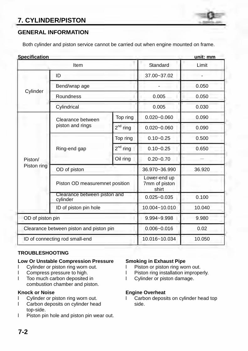
GENERAL INFORMATION ü Both cylinder and piston service cannot be carried out when engine mounted on frame. Specification unit: mm
Item Standard Limit
Cylinder
ID 37.00~37.02 -
Bend/wrap age - 0.050
Roundness 0.005 0.050
Cylindrical 0.005 0.030
Piston/ Piston ring
Clearance between piston and rings
Top ring 0.020~0.060 0.090
2nd ring 0.020~0.060 0.090
Ring-end gap
Top ring 0.10~0.25 0.500
2nd ring 0.10~0.25 0.650
Oil ring 0.20~0.70 -
OD of piston 36.970~36.990 36.920
Piston OD measuremnet position Lower-end up 7mm of piston
shirt
Clearance between piston and cylinder 0.025~0.035 0.100
ID of piston pin hole 10.004~10.010 10.040
OD of piston pin 9.994~9.998 9.980
Clearance between piston and piston pin 0.006~0.016 0.02
ID of connecting rod small-end 10.016~10.034 10.050 TROUBLESHOOTING Low Or Unstable Compression Pressure l Cylinder or piston ring worn out. l Compress pressure to high. l Too much carbon deposited in
combustion chamber and piston. Knock or Noise l Cylinder or piston ring worn out. l Carbon deposits on cylinder head
top-side.
Smoking in Exhaust Pipe l Piston or piston ring worn out. l Piston ring installation improperly. l Cylinder or piston damage. Engine Overheat l Carbon deposits on cylinder head top
side.
l Piston pin hole and piston pin wear out.
= 0+
7. CYLINDER/PISTON
7-3
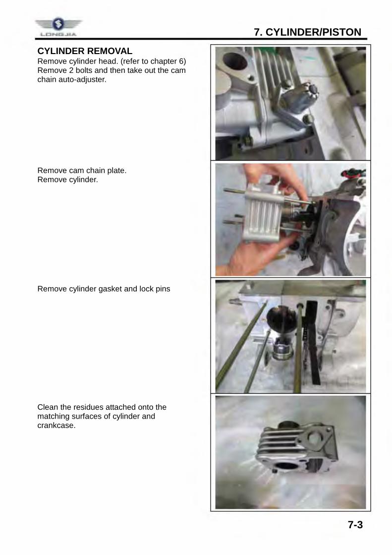
CYLINDER REMOVAL Remove cylinder head. (refer to chapter 6) Remove 2 bolts and then take out the cam chain auto-adjuster. Remove cam chain plate. Remove cylinder. Remove cylinder gasket and lock pins Clean the residues attached onto the matching surfaces of cylinder and crankcase.
= LONQ..llA
7. CYLINDER/PISTON
7-4
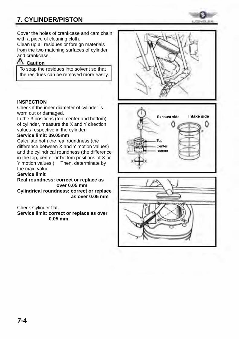
Cover the holes of crankcase and cam chain with a piece of cleaning cloth. Clean up all residues or foreign materials from the two matching surfaces of cylinder and crankcase.
Caution INSPECTION Check if the inner diameter of cylinder is worn out or damaged. In the 3 positions (top, center and bottom) of cylinder, measure the X and Y direction values respective in the cylinder. Service limit: 39.05mm Calculate both the real roundness (the difference between X and Y motion values) and the cylindrical roundness (the difference in the top, center or bottom positions of X or Y motion values.). Then, determinate by the max. value. Service limit Real roundness: correct or replace as
over 0.05 mm Cylindrical roundness: correct or replace
as over 0.05 mm Check Cylinder flat. Service limit: correct or replace as over
0.05 mm
To soap the residues into solvent so that the residues can be removed more easily.
Top Center Bottom
Exhaust side Intake side
= 0+
¢ , · . 0 • .. ,
, ' ~- ~;
!',. .. _ .._ •••
7. CYLINDER/PISTON
7-5
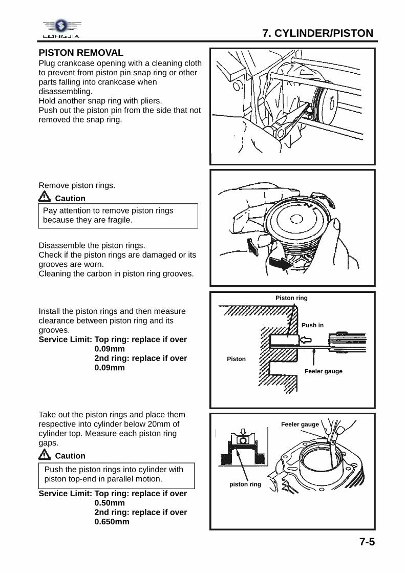
PISTON REMOVAL Plug crankcase opening with a cleaning cloth to prevent from piston pin snap ring or other parts falling into crankcase when disassembling. Hold another snap ring with pliers. Push out the piston pin from the side that not removed the snap ring. Remove piston rings.
Caution Disassemble the piston rings. Check if the piston rings are damaged or its grooves are worn. Cleaning the carbon in piston ring grooves. Install the piston rings and then measure clearance between piston ring and its grooves. Service Limit: Top ring: replace if over
0.09mm 2nd ring: replace if over
0.09mm Take out the piston rings and place them respective into cylinder below 20mm of cylinder top. Measure each piston ring gaps.
Caution Service Limit: Top ring: replace if over
0.50mm 2nd ring: replace if over
0.650mm
Pay attention to remove piston rings because they are fragile.
Push the piston rings into cylinder with piston top-end in parallel motion.
Piston ring
Push in
Feeler gauge
Piston
piston ring
Feeler gauge
.&~----1 IL ___ _
_&~-- - ----1 IL __ _
7. CYLINDER/PISTON
7-6
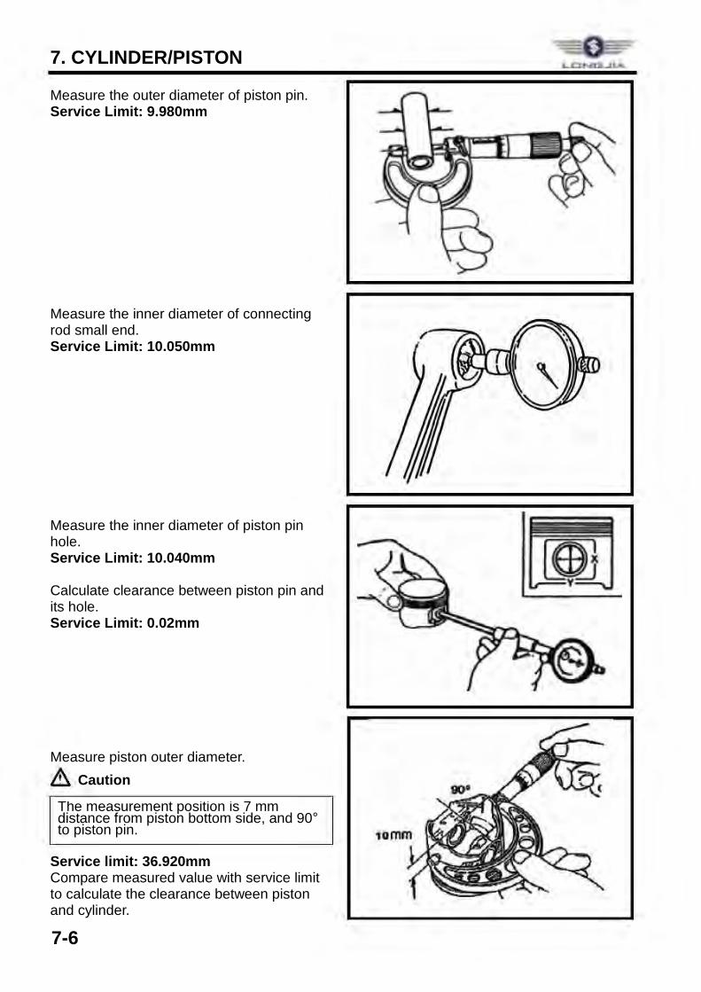
Measure the outer diameter of piston pin. Service Limit: 9.980mm Measure the inner diameter of connecting rod small end. Service Limit: 10.050mm Measure the inner diameter of piston pin hole. Service Limit: 10.040mm Calculate clearance between piston pin and its hole. Service Limit: 0.02mm Measure piston outer diameter.
Caution Service limit: 36.920mm Compare measured value with service limit to calculate the clearance between piston and cylinder.
The measurement position is 7 mm distance from piston bottom side, and 90° to piston pin.
LONa..llA
7. CYLINDER/PISTON
7-7
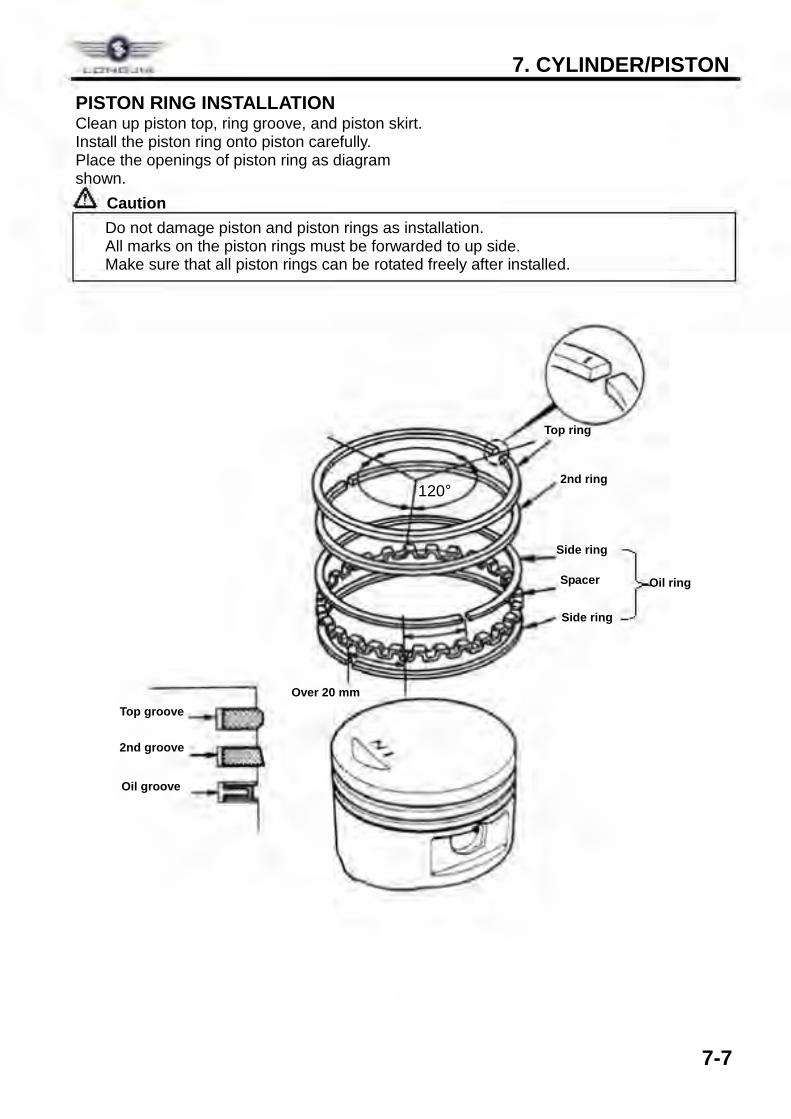
PISTON RING INSTALLATION Clean up piston top, ring groove, and piston skirt. Install the piston ring onto piston carefully. Place the openings of piston ring as diagram shown.
Caution
ü Do not damage piston and piston rings as installation. ü All marks on the piston rings must be forwarded to up side. ü Make sure that all piston rings can be rotated freely after installed.
Top groove
2nd groove
Oil groove
Top ring
2nd ring
Oil ring Spacer
Side ring
Side ring
Over 20 mm
120°
}
7. CYLINDER/PISTON
7-8
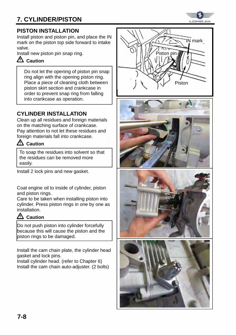
PISTON INSTALLATION Install piston and piston pin, and place the IN mark on the piston top side forward to intake valve. Install new piston pin snap ring.
Caution
CYLINDER INSTALLATION Clean up all residues and foreign materials on the matching surface of crankcase. Pay attention to not let these residues and foreign materials fall into crankcase.
Caution Install 2 lock pins and new gasket. Coat engine oil to inside of cylinder, piston and piston rings. Care to be taken when installing piston into cylinder. Press piston rings in one by one as installation.
Caution Install the cam chain plate, the cylinder head gasket and lock pins. Install cylinder head. (refer to Chapter 6) Install the cam chain auto-adjuster. (2 bolts)
ü Do not let the opening of piston pin snap ring align with the opening piston ring. ü Place a piece of cleaning cloth between
piston skirt section and crankcase in order to prevent snap ring from falling into crankcase as operation.
Do not push piston into cylinder forcefully because this will cause the piston and the piston rings to be damaged.
To soap the residues into solvent so that the residues can be removed more easily.
Piston pin
IN mark
Piston
LctNICJl..ilA
&. 1---
8. V-BELT DRIVING SYSTEM / KICK STARTER SYSTEM
8-1
COMPONENT STRUCTURE ............. 8-1 GENERAL INFORMATION ................ 8-2 TROUBLESHOOTING ....................... 8-2 LEFT CRANKCASE COVER ............. 8-3
KICK STARTER ARM ......................... 8-3 DRIVING BELT ................................... 8-4 SLIDING PULLEY ............................... 8-6 CLUTCH/DRIVEN PULLEY ............... 8-9
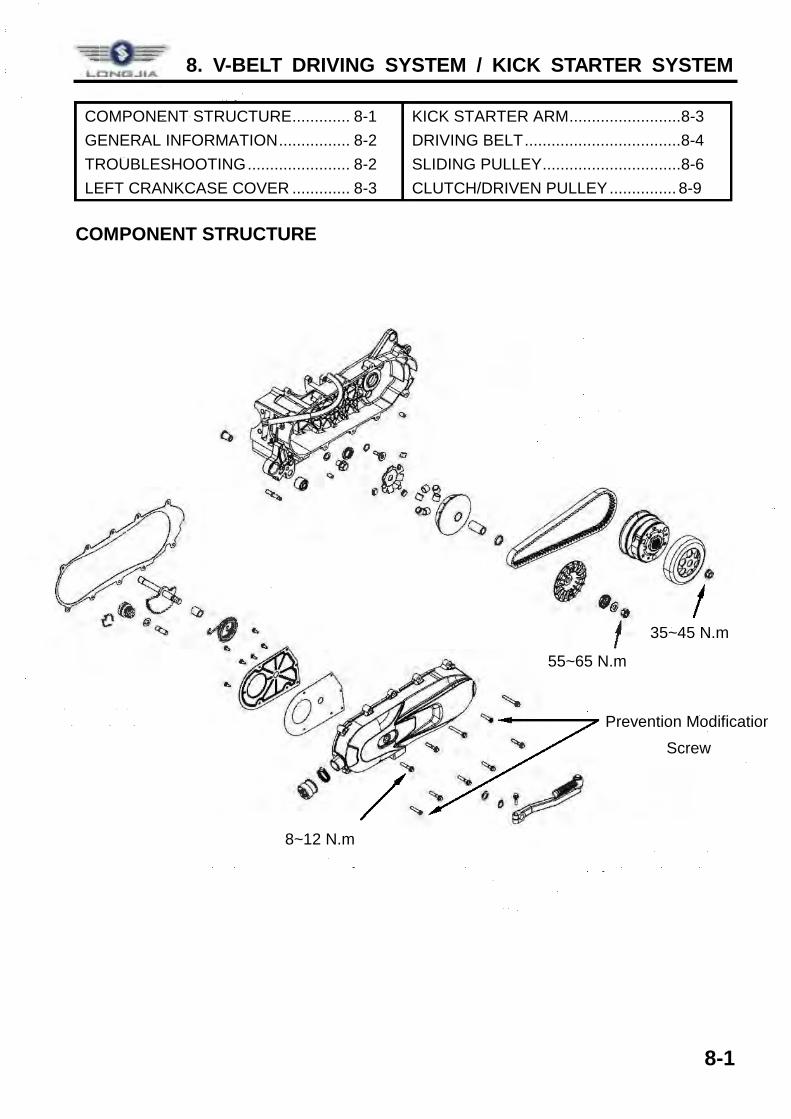
COMPONENT STRUCTURE
55~65 N.m
35~45 N.m
8~12 N.m
Prevention ModificationScrew
8. V-BELT DRIVING SYSTEM / KICK STARTER SYSTEM
8-2
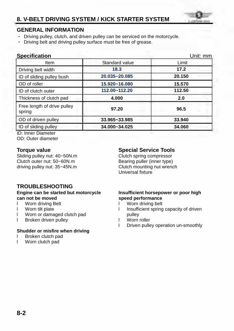
GENERAL INFORMATION ‧ Driving pulley, clutch, and driven pulley can be serviced on the motorcycle. ‧ Driving belt and driving pulley surface must be free of grease.
Specification Unit: mm Item Standard value Limit
Driving belt width 18.3 17.2 ID of sliding pulley bush 20.035~20.085 20.150 OD of roller 15.920~16.080 15.570 ID of clutch outer 112.00~112.20 112.50 Thickness of clutch pad 4.000 2.0 Free length of drive pulley spring 97.20 96.5
OD of driven pulley 33.965~33.985 33.940 ID of sliding pulley 34.000~34.025 34.060
ID: Inner Diameter OD: Outer diameter Torque value Sliding pulley nut: 40~50N.m Clutch outer nut: 50~60N.m driving pulley nut: 35~45N.m
Special Service Tools Clutch spring compressor Bearing puller (inner type) Clutch mounting nut wrench Universal fixture
TROUBLESHOOTING Engine can be started but motorcycle can not be moved l Worn driving Belt l Worn tilt plate l Worn or damaged clutch pad l Broken driven pulley Shudder or misfire when driving l Broken clutch pad l Worn clutch pad
Insufficient horsepower or poor high speed performance l Worn driving belt l Insufficient spring capacity of driven
pulley l Worn roller l Driven pulley operation un-smoothly
L.CINt:l.,UA
8. V-BELT DRIVING SYSTEM / KICK STARTER SYSTEM
8-3
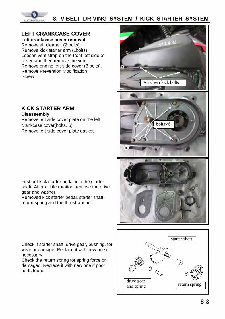
LEFT CRANKCASE COVER Left crankcase cover removal Remove air cleaner. (2 bolts) Remove kick starter arm (1bolts) Loosen vent strap on the front-left side of cover, and then remove the vent. Remove engine left-side cover (8 bolts). Remove Prevention Modification Screw KICK STARTER ARM Disassembly Remove left side cover plate on the left crankcase cover(bolts×6). Remove left side cover plate gasket.
First put kick starter pedal into the starter shaft. After a little rotation, remove the drive gear and washer. Removed kick starter pedal, starter shaft, return spring and the thrust washer. Check if starter shaft, drive gear, bushing, for wear or damage. Replace it with new one if necessary. Check the return spring for spring force or damaged. Replace it with new one if poor parts found.
Air clean lock bolts
bolts×6
return spring
starter shaft
drive gear and spring
I I __ _
8. V-BELT DRIVING SYSTEM / KICK STARTER SYSTEM
8-4
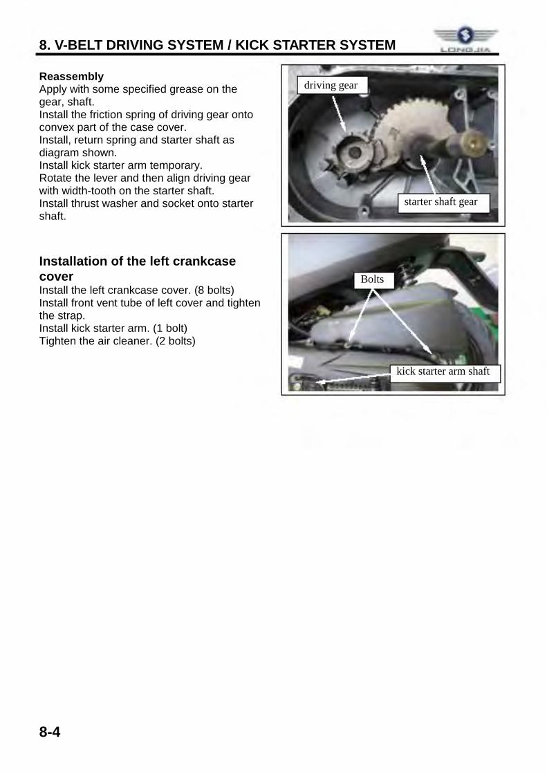
Reassembly Apply with some specified grease on the gear, shaft. Install the friction spring of driving gear onto convex part of the case cover. Install, return spring and starter shaft as diagram shown. Install kick starter arm temporary. Rotate the lever and then align driving gear with width-tooth on the starter shaft. Install thrust washer and socket onto starter shaft. Installation of the left crankcase cover Install the left crankcase cover. (8 bolts) Install front vent tube of left cover and tighten the strap. Install kick starter arm. (1 bolt) Tighten the air cleaner. (2 bolts)
driving gear
starter shaft gear
kick starter arm shaft
Bolts
8. V-BELT DRIVING SYSTEM / KICK STARTER SYSTEM
8-5
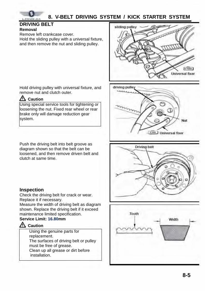
DRIVING BELT Removal Remove left crankcase cover. Hold the sliding pulley with a universal fixture, and then remove the nut and sliding pulley. Hold driving pulley with universal fixture, and remove nut and clutch outer.
Caution Push the driving belt into belt groove as diagram shown so that the belt can be loosened, and then remove driven belt and clutch at same time. Inspection Check the driving belt for crack or wear. Replace it if necessary. Measure the width of driving belt as diagram shown. Replace the driving belt if it exceed maintenance limited specification. Service Limit: 16.80mm
Caution
Using special service tools for tightening or loosening the nut. Fixed rear wheel or rear brake only will damage reduction gear system.
ü Using the genuine parts for replacement.
ü The surfaces of driving belt or pulley must be free of grease.
ü Clean up all grease or dirt before installation.
L0Nd • .HA
Tooth
i -i ~
Width
8. V-BELT DRIVING SYSTEM / KICK STARTER SYSTEM
8-6
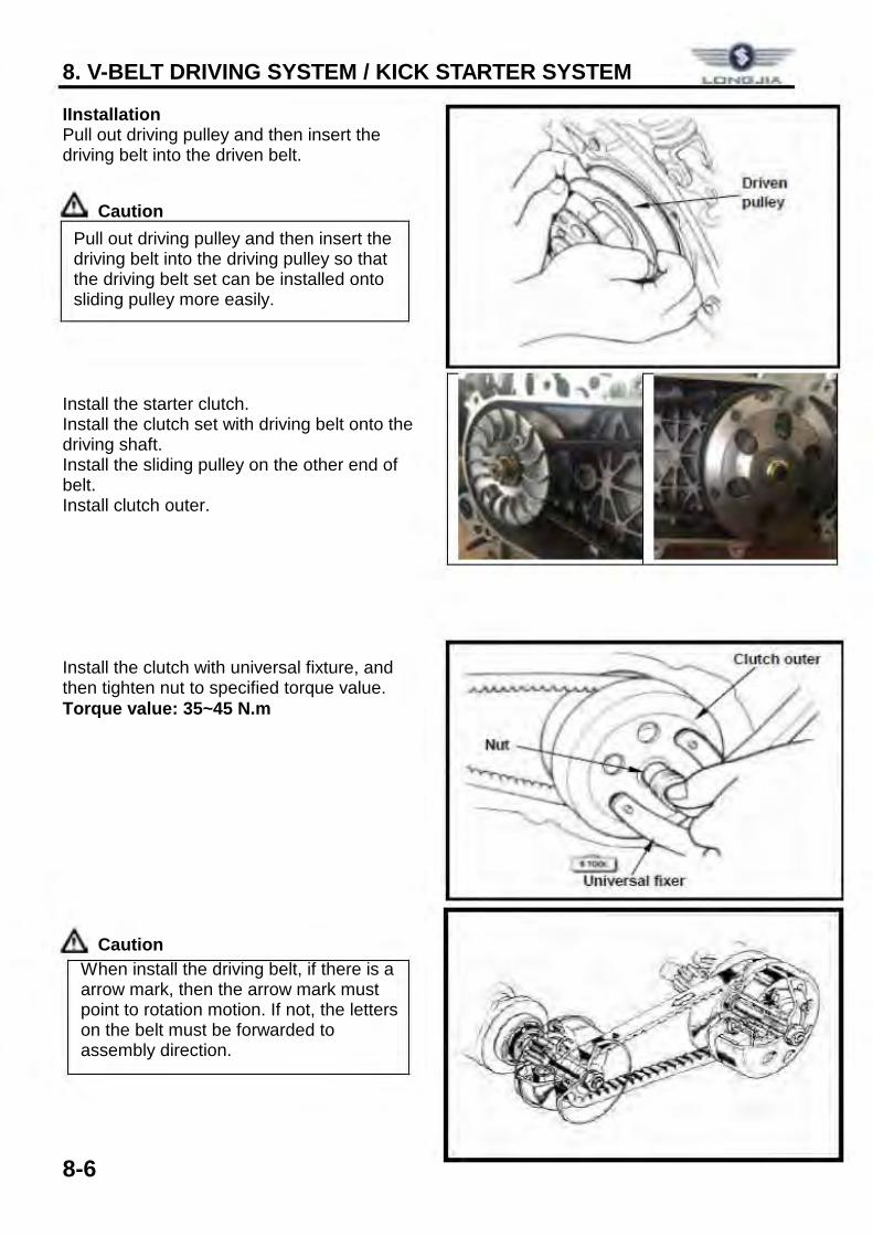
IInstallation Pull out driving pulley and then insert the driving belt into the driven belt.
Caution Install the starter clutch. Install the clutch set with driving belt onto the driving shaft. Install the sliding pulley on the other end of belt. Install clutch outer. Install the clutch with universal fixture, and then tighten nut to specified torque value. Torque value: 35~45 N.m
Caution
Pull out driving pulley and then insert the driving belt into the driving pulley so that the driving belt set can be installed onto sliding pulley more easily.
When install the driving belt, if there is a arrow mark, then the arrow mark must point to rotation motion. If not, the letters on the belt must be forwarded to assembly direction.
Driven ~ .i-"l~..:---pulley
.-;;. t Universal fixer
Clutch outer
8. V-BELT DRIVING SYSTEM / KICK STARTER SYSTEM
8-7
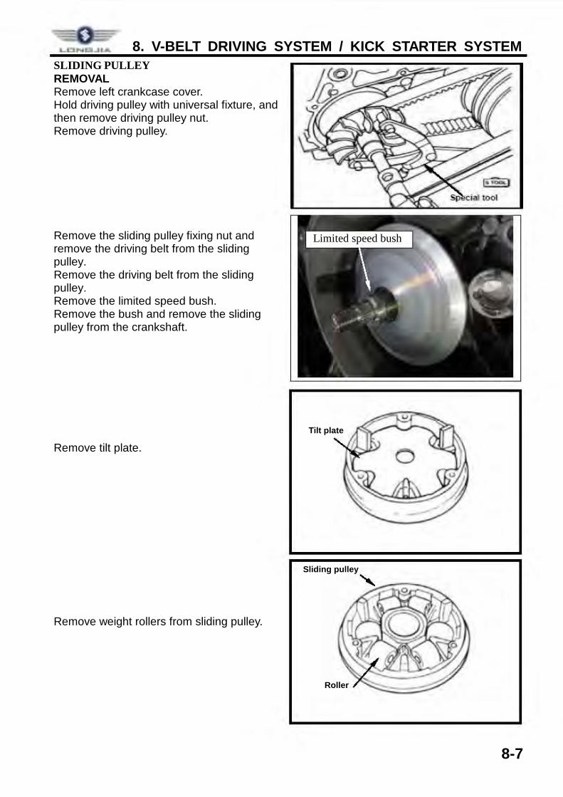
SLIDING PULLEY REMOVAL Remove left crankcase cover. Hold driving pulley with universal fixture, and then remove driving pulley nut. Remove driving pulley. Remove the sliding pulley fixing nut and remove the driving belt from the sliding pulley. Remove the driving belt from the sliding pulley. Remove the limited speed bush. Remove the bush and remove the sliding pulley from the crankshaft. Remove tilt plate. Remove weight rollers from sliding pulley.
Tilt plate
Sliding pulley
Roller
Limited speed bush
LONta....il.A.
8. V-BELT DRIVING SYSTEM / KICK STARTER SYSTEM
8-8
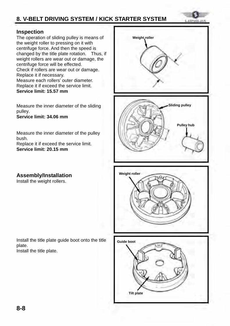
Inspection The operation of sliding pulley is means of the weight roller to pressing on it with centrifuge force. And then the speed is changed by the title plate rotation. Thus, if weight rollers are wear out or damage, the centrifuge force will be effected. Check if rollers are wear out or damage. Replace it if necessary. Measure each rollers’ outer diameter. Replace it if exceed the service limit. Service limit: 15.57 mm Measure the inner diameter of the sliding pulley. Service limit: 34.06 mm
Measure the inner diameter of the pulley bush. Replace it if exceed the service limit. Service limit: 20.15 mm Assembly/Installation Install the weight rollers. Install the title plate guide boot onto the title plate. Install the title plate.
Weight roller
Sliding pulley
Pulley hub
Guide boot
Tilt plate
Weight roller
8. V-BELT DRIVING SYSTEM / KICK STARTER SYSTEM
8-9
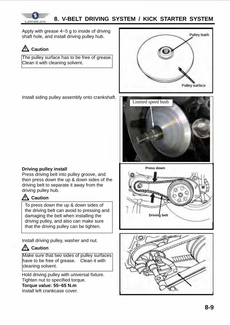
Apply with grease 4~5 g to inside of driving shaft hole, and install driving pulley hub.
Caution Install siding pulley assembly onto crankshaft. Driving pulley install Press driving belt into pulley groove, and then press down the up & down sides of the driving belt to separate it away from the driving pulley hub.
Caution Install driving pulley, washer and nut.
Caution Hold driving pulley with universal fixture. Tighten nut to specified torque. Torque value: 55~65 N.m Install left crankcase cover.
The pulley surface has to be free of grease. Clean it with cleaning solvent.
Make sure that two sides of pulley surfaces have to be free of grease. Clean it with cleaning solvent.
To press down the up & down sides of the driving belt can avoid to pressing and damaging the belt when installing the driving pulley, and also can make sure that the driving pulley can be tighten.
Driving belt
Press down
Limited speed bush
LCI.NQ...JIA
Pulley surface
8. V-BELT DRIVING SYSTEM / KICK STARTER SYSTEM
8-10
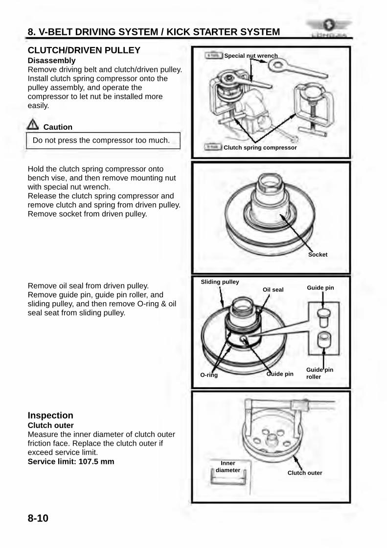
CLUTCH/DRIVEN PULLEY Disassembly Remove driving belt and clutch/driven pulley. Install clutch spring compressor onto the pulley assembly, and operate the compressor to let nut be installed more easily.
Caution Hold the clutch spring compressor onto bench vise, and then remove mounting nut with special nut wrench. Release the clutch spring compressor and remove clutch and spring from driven pulley. Remove socket from driven pulley. Remove oil seal from driven pulley. Remove guide pin, guide pin roller, and sliding pulley, and then remove O-ring & oil seal seat from sliding pulley. Inspection Clutch outer Measure the inner diameter of clutch outer friction face. Replace the clutch outer if exceed service limit. Service limit: 107.5 mm
Do not press the compressor too much.
Clutch outer Inner
diameter
O-ring Guide pin Guide pin roller
Guide pin Oil seal Sliding pulley
Socket
Clutch spring compressor
Special nut wrench
8. V-BELT DRIVING SYSTEM / KICK STARTER SYSTEM
8-11
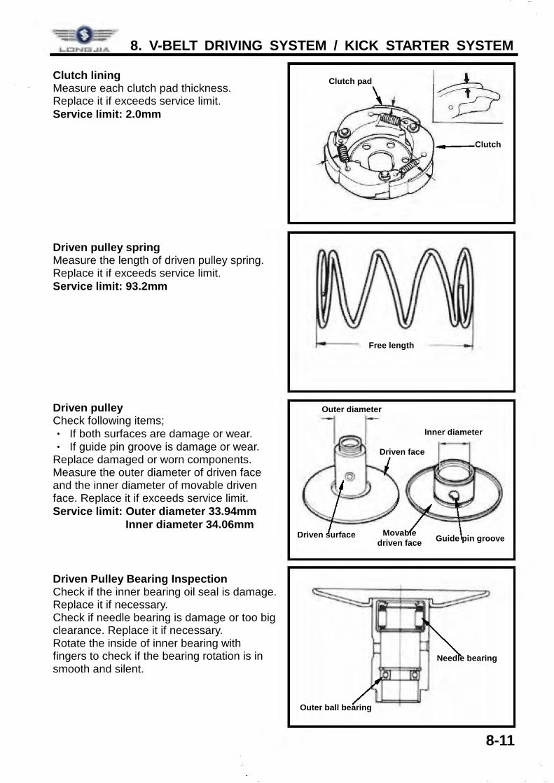
Clutch lining Measure each clutch pad thickness. Replace it if exceeds service limit. Service limit: 2.0mm Driven pulley spring Measure the length of driven pulley spring. Replace it if exceeds service limit. Service limit: 93.2mm Driven pulley Check following items; ‧ If both surfaces are damage or wear. ‧ If guide pin groove is damage or wear. Replace damaged or worn components. Measure the outer diameter of driven face and the inner diameter of movable driven face. Replace it if exceeds service limit. Service limit: Outer diameter 33.94mm Inner diameter 34.06mm Driven Pulley Bearing Inspection Check if the inner bearing oil seal is damage. Replace it if necessary. Check if needle bearing is damage or too big clearance. Replace it if necessary. Rotate the inside of inner bearing with fingers to check if the bearing rotation is in smooth and silent.
Free length
Clutch
Clutch pad
Needle bearing
Outer ball bearing
Guide pin groove Movable
driven face
Driven face
Driven surface
Outer diameter
Inner diameter
8. V-BELT DRIVING SYSTEM / KICK STARTER SYSTEM
8-12
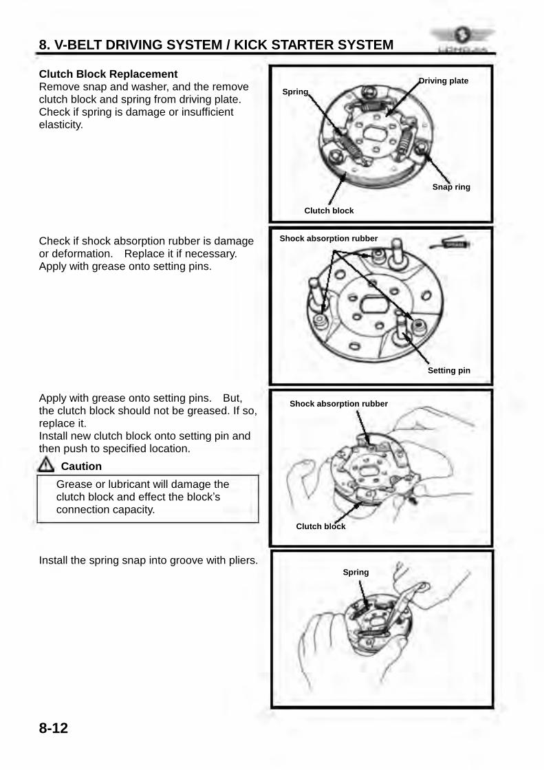
Clutch Block Replacement Remove snap and washer, and the remove clutch block and spring from driving plate. Check if spring is damage or insufficient elasticity. Check if shock absorption rubber is damage or deformation. Replace it if necessary. Apply with grease onto setting pins. Apply with grease onto setting pins. But, the clutch block should not be greased. If so, replace it. Install new clutch block onto setting pin and then push to specified location.
Caution Install the spring snap into groove with pliers.
ü Grease or lubricant will damage the clutch block and effect the block’s connection capacity.
Shock absorption rubber
Clutch block
Spring
Spring Driving plate
Snap ring
Clutch block
Shock absorption rubber
Setting pin
8. V-BELT DRIVING SYSTEM / KICK STARTER SYSTEM
8-13
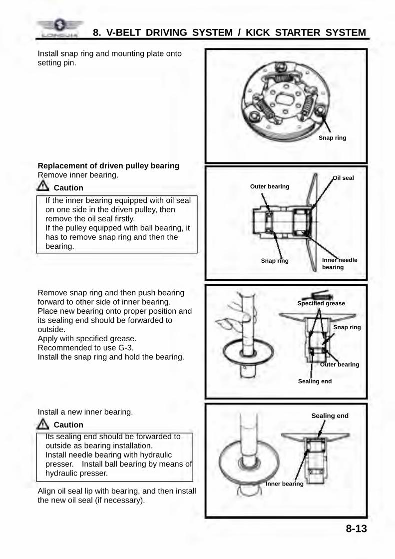
Install snap ring and mounting plate onto setting pin. Replacement of driven pulley bearing Remove inner bearing.
Caution Remove snap ring and then push bearing forward to other side of inner bearing. Place new bearing onto proper position and its sealing end should be forwarded to outside. Apply with specified grease. Recommended to use G-3. Install the snap ring and hold the bearing. Install a new inner bearing.
Caution Align oil seal lip with bearing, and then install the new oil seal (if necessary).
ü Its sealing end should be forwarded to outside as bearing installation. ü Install needle bearing with hydraulic
presser. Install ball bearing by means of hydraulic presser.
ü If the inner bearing equipped with oil seal on one side in the driven pulley, then remove the oil seal firstly. ü If the pulley equipped with ball bearing, it
has to remove snap ring and then the bearing.
Snap ring
Inner bearing
Sealing end
Oil seal
Inner needle bearing
Outer bearing
Snap ring
Snap ring
Outer bearing
Sealing end
Specified grease
Lc:INCl.,UA
., Gr
8. V-BELT DRIVING SYSTEM / KICK STARTER SYSTEM
8-14
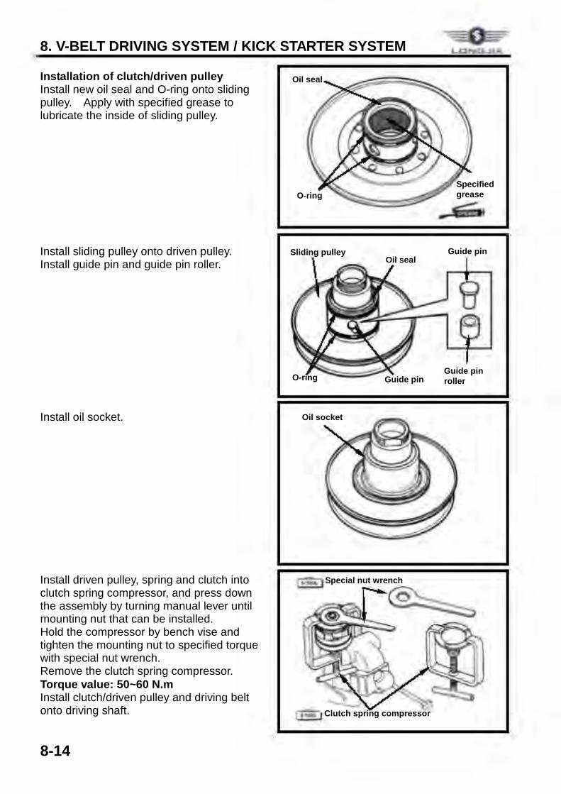
Installation of clutch/driven pulley Install new oil seal and O-ring onto sliding pulley. Apply with specified grease to lubricate the inside of sliding pulley. Install sliding pulley onto driven pulley. Install guide pin and guide pin roller. Install oil socket. Install driven pulley, spring and clutch into clutch spring compressor, and press down the assembly by turning manual lever until mounting nut that can be installed. Hold the compressor by bench vise and tighten the mounting nut to specified torque with special nut wrench. Remove the clutch spring compressor. Torque value: 50~60 N.m Install clutch/driven pulley and driving belt onto driving shaft.
Oil seal
O-ring Specified grease
Oil socket
O-ring Guide pin Guide pin roller
Guide pin Oil seal
Sliding pulley
Clutch spring compressor
Special nut wrench
L.CINt:l.,UA
9. FINAL DRIVING SYSTEM
9-1
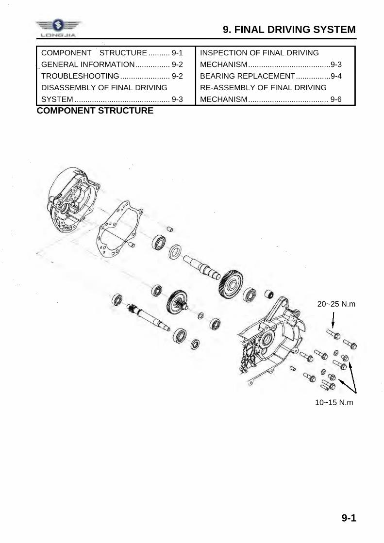
COMPONENT STRUCTURE .......... 9-1 GENERAL INFORMATION ................ 9-2 TROUBLESHOOTING ....................... 9-2 DISASSEMBLY OF FINAL DRIVING SYSTEM ............................................ 9-3
INSPECTION OF FINAL DRIVING MECHANISM ...................................... 9-3 BEARING REPLACEMENT ................ 9-4 RE-ASSEMBLY OF FINAL DRIVING MECHANISM ..................................... 9-6
COMPONENT STRUCTURE
20~25 N.m
10~15 N.m
9. FINAL DRIVING SYSTEM
9-2
GENERAL INFORMATION Specification Application gear oil: 4-stroke lubricant Recommended gear oil:80W-90 Oil quantity: 140 c.c. (120 c.c. when replacing) Tools Special service tools Inner type bearing puller Outer type bearing puller Gear box oil seal installer Gear box bearing installer
Torque value Gear box cover 20~25 N.m Gear oil drain plug 10~15 N.m Gear oil filling bolt 10~15 N.m
TROUBLESHOOTING Engine can be started but motorcycle can not be moved l Damaged driving gear l Burnt out driving gear l Broken driving belt Noise l Worn or burnt gear l Worn gear
Gear oil leaks l Excessive gear oil l Worn or damage oil seal
9. FINAL DRIVING SYSTEM
9-3
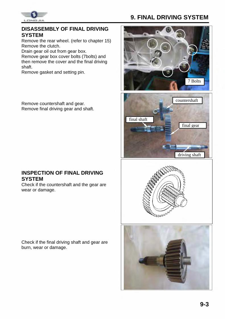
DISASSEMBLY OF FINAL DRIVING SYSTEM Remove the rear wheel. (refer to chapter 15) Remove the clutch. Drain gear oil out from gear box. Remove gear box cover bolts (7bolts) and then remove the cover and the final driving shaft. Remove gasket and setting pin. Remove countershaft and gear. Remove final driving gear and shaft. INSPECTION OF FINAL DRIVING SYSTEM Check if the countershaft and the gear are wear or damage. Check if the final driving shaft and gear are burn, wear or damage.
driving shaft
countershaft
final shaft final gear
7 Bolts
9. FINAL DRIVING SYSTEM
9-4
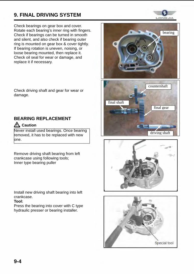
Check bearings on gear box and cover. Rotate each bearing’s inner ring with fingers. Check if bearings can be turned in smooth and silent, and also check if bearing outer ring is mounted on gear box & cover tightly. If bearing rotation is uneven, noising, or loose bearing mounted, then replace it. Check oil seal for wear or damage, and replace it if necessary. Check driving shaft and gear for wear or damage. BEARING REPLACEMENT
Caution Remove driving shaft bearing from left crankcase using following tools; Inner type bearing puller Install new driving shaft bearing into left crankcase. Tool: Press the bearing into cover with C type hydraulic presser or bearing installer.
Never install used bearings. Once bearing removed, it has to be replaced with new one.
driving shaft
countershaft
final shaft final gear
bearing
& i--___ l
'
-.,..
Special tool
9. FINAL DRIVING SYSTEM
9-5
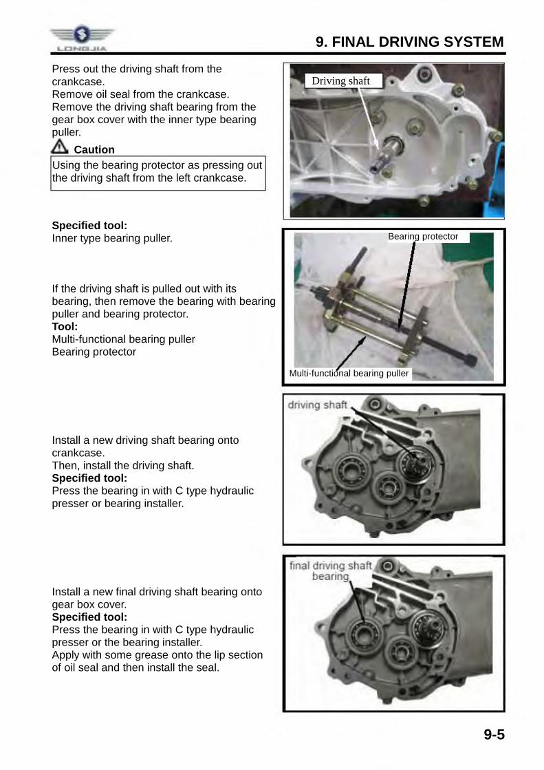
Press out the driving shaft from the crankcase. Remove oil seal from the crankcase. Remove the driving shaft bearing from the gear box cover with the inner type bearing puller.
Caution Specified tool: Inner type bearing puller. If the driving shaft is pulled out with its bearing, then remove the bearing with bearing puller and bearing protector. Tool: Multi-functional bearing puller Bearing protector Install a new driving shaft bearing onto crankcase. Then, install the driving shaft. Specified tool: Press the bearing in with C type hydraulic presser or bearing installer. Install a new final driving shaft bearing onto gear box cover. Specified tool: Press the bearing in with C type hydraulic presser or the bearing installer. Apply with some grease onto the lip section of oil seal and then install the seal.
Using the bearing protector as pressing out the driving shaft from the left crankcase.
Bearing protector
Multi-functional bearing puller
Driving shaft
driving shaft
9. FINAL DRIVING SYSTEM
9-6
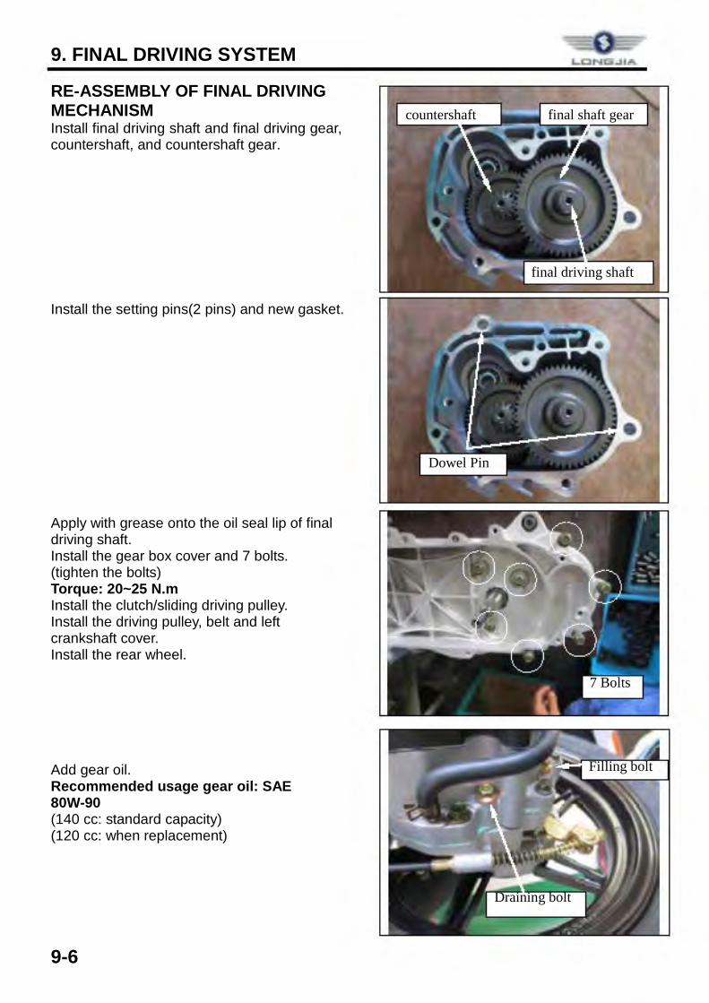
RE-ASSEMBLY OF FINAL DRIVING MECHANISM Install final driving shaft and final driving gear, countershaft, and countershaft gear.
Install the setting pins(2 pins) and new gasket. Apply with grease onto the oil seal lip of final driving shaft. Install the gear box cover and 7 bolts. (tighten the bolts) Torque: 20~25 N.m Install the clutch/sliding driving pulley. Install the driving pulley, belt and left crankshaft cover. Install the rear wheel. Add gear oil. Recommended usage gear oil: SAE 80W-90 (140 cc: standard capacity) (120 cc: when replacement)
7 Bolts
countershaft
final driving shaft
final shaft gear
Dowel Pin
Filling bolt
Draining bolt
10. A.C. GENERATOR
10-1
COMPONENT STRUCTURE .......... 10-1 GENERAL INFORMATION ................ 10-1 A.C.GENERATOR REMOVAL ........... 10-2 RIGHT CRANKCASE COVER REMOVAL ......................................... 10-3
RIGHT CRANKCASE COVER INSTALLATION .................................. 10-4 MOUNTED COIL SET INSTALLATION .................................. 10-4 FLY WHEEL INSTALLATION ............. 10-4
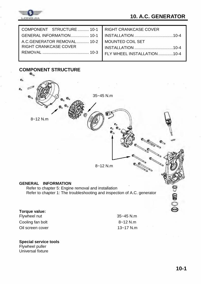
COMPONENT STRUCTURE
GENERAL INFORMATION ü Refer to chapter 5: Engine removal and installation ü Refer to chapter 1: The troubleshooting and inspection of A.C. generator Torque value: Flywheel nut 35~45 N.m Cooling fan bolt 8~12 N.m Oil screen cover 13~17 N.m Special service tools Flywheel puller Universal fixture
8~12 N.m
35~45 N.m
8~12 N.m
LCNtll..JIA
I I -,
I _J
10. A.C. GENERATOR/STARTING CLUTCH
10-2
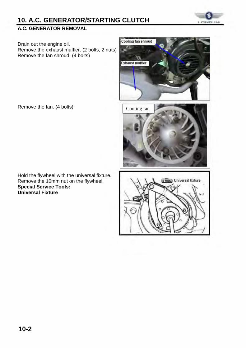
A.C. GENERATOR REMOVAL
Drain out the engine oil. Remove the exhaust muffler. (2 bolts, 2 nuts) Remove the fan shroud. (4 bolts) Remove the fan. (4 bolts) Hold the flywheel with the universal fixture. Remove the 10mm nut on the flywheel. Special Service Tools: Universal Fixture
Cooling fan
= LONO...lkA
0
10. A.C. GENERATOR
10-3
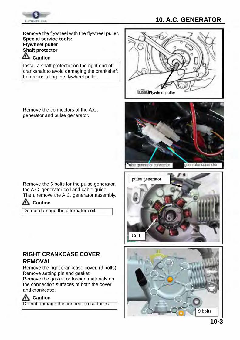
Remove the flywheel with the flywheel puller. Special service tools: Flywheel puller Shaft protector
Caution
Remove the connectors of the A.C. generator and pulse generator. Remove the 6 bolts for the pulse generator, the A.C. generator coil and cable guide. Then, remove the A.C. generator assembly.
Caution
RIGHT CRANKCASE COVER REMOVAL Remove the right crankcase cover. (9 bolts) Remove setting pin and gasket. Remove the gasket or foreign materials on the connection surfaces of both the cover and crankcase.
Caution
Do not damage the alternator coil.
Do not damage the connection surfaces.
Install a shaft protector on the right end of crankshaft to avoid damaging the crankshaft before installing the flywheel puller.
Flywheel puller
9 bolts
Coil
pulse generator
10. A.C. GENERATOR/STARTING CLUTCH
10-4
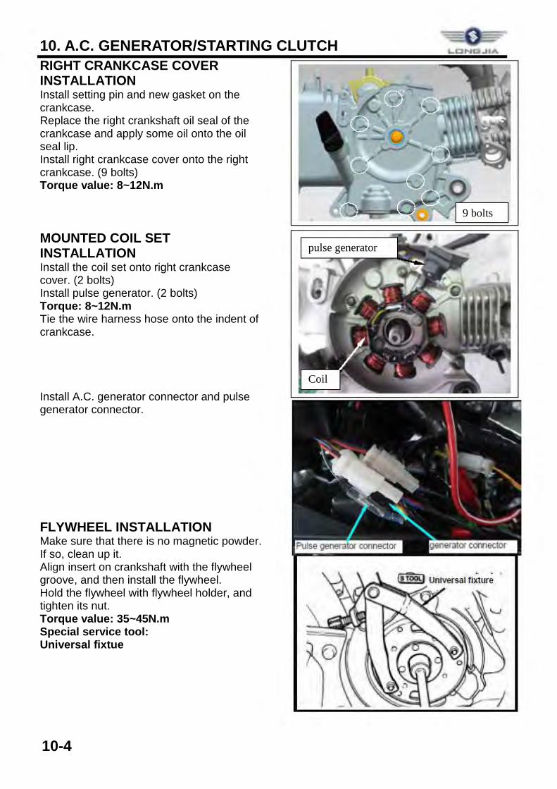
RIGHT CRANKCASE COVER INSTALLATION Install setting pin and new gasket on the crankcase. Replace the right crankshaft oil seal of the crankcase and apply some oil onto the oil seal lip. Install right crankcase cover onto the right crankcase. (9 bolts) Torque value: 8~12N.m MOUNTED COIL SET INSTALLATION Install the coil set onto right crankcase cover. (2 bolts) Install pulse generator. (2 bolts) Torque: 8~12N.m Tie the wire harness hose onto the indent of crankcase. Install A.C. generator connector and pulse generator connector. FLYWHEEL INSTALLATION Make sure that there is no magnetic powder. If so, clean up it. Align insert on crankshaft with the flywheel groove, and then install the flywheel. Hold the flywheel with flywheel holder, and tighten its nut. Torque value: 35~45N.m Special service tool: Universal fixtue
9 bolts
Coil
pulse generator
0
10. A.C. GENERATOR
10-5
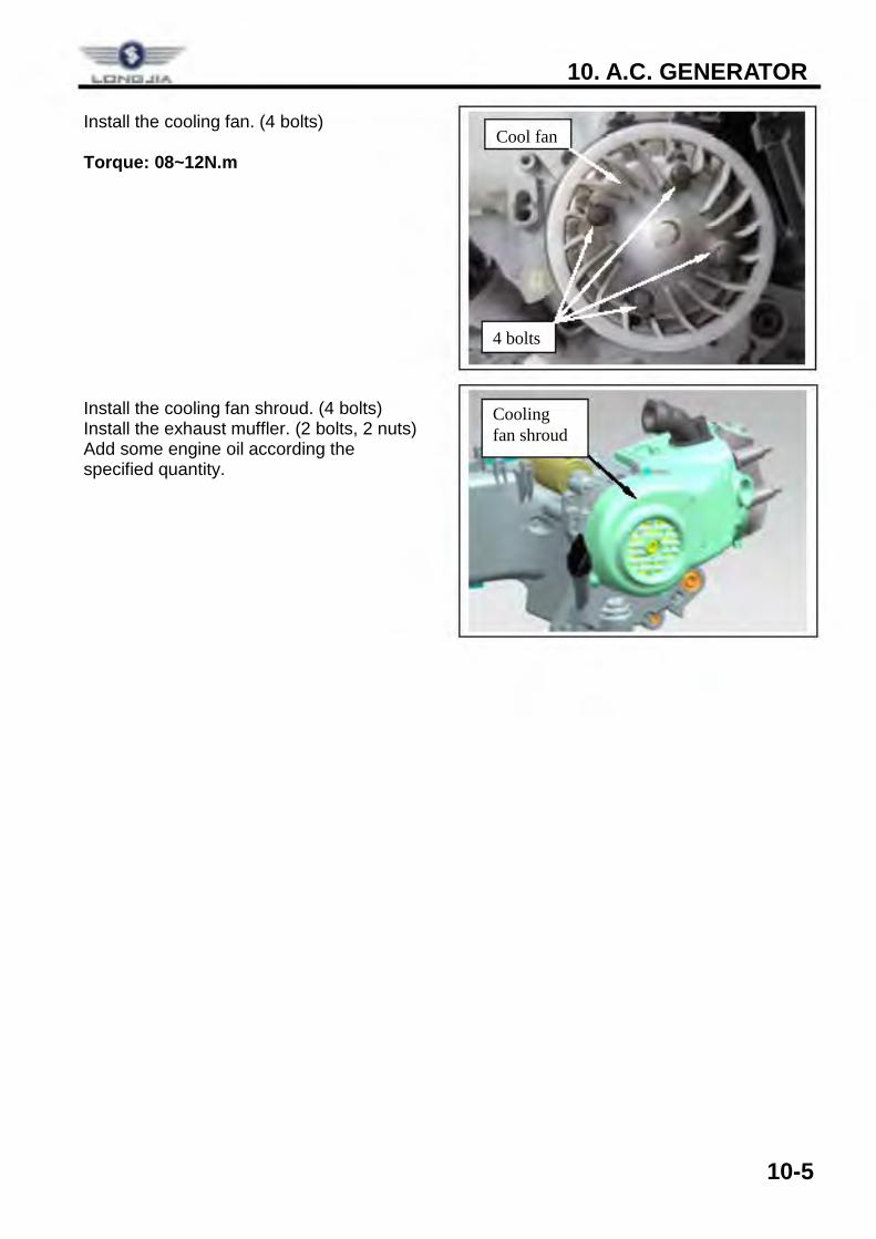
Install the cooling fan. (4 bolts) Torque: 08~12N.m
Install the cooling fan shroud. (4 bolts) Install the exhaust muffler. (2 bolts, 2 nuts) Add some engine oil according the specified quantity.
Cool fan
4 bolts
Cooling fan shroud
LONO..IIA
11. CRANKCASE/CRANKSHAFT
11-1
COMPONENT STRUCTURE ...... 11-1 GENERAL INFORMATION .......... 11-2 TROUBLESHOOTING ................ 11-2
DISASSEMBLY OF CRANKCASE . 11-3 CRANKSHAFT INSPECTION ....... 11-5 ASSEMBLY OF CRANKCASE ...... 11-6
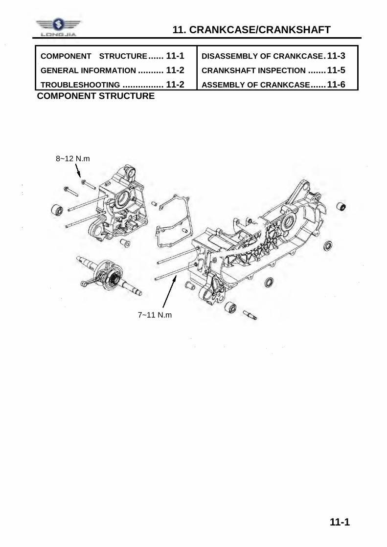
COMPONENT STRUCTURE
8~12 N.m
7~11 N.m
0 0
11. CRANKCASE/CRANKSHAFT
11-2
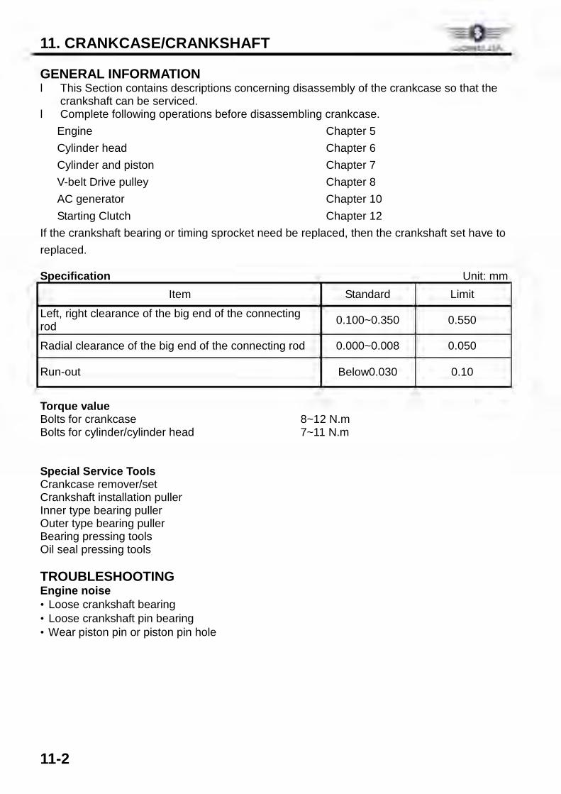
GENERAL INFORMATION l This Section contains descriptions concerning disassembly of the crankcase so that the
crankshaft can be serviced. l Complete following operations before disassembling crankcase.
Engine Chapter 5 Cylinder head Chapter 6 Cylinder and piston Chapter 7 V-belt Drive pulley Chapter 8 AC generator Chapter 10 Starting Clutch Chapter 12
If the crankshaft bearing or timing sprocket need be replaced, then the crankshaft set have to replaced. Specification Unit: mm
Item Standard Limit
Left, right clearance of the big end of the connecting rod 0.100~0.350 0.550
Radial clearance of the big end of the connecting rod 0.000~0.008 0.050
Run-out Below0.030 0.10
Torque value Bolts for crankcase 8~12 N.m Bolts for cylinder/cylinder head 7~11 N.m Special Service Tools Crankcase remover/set Crankshaft installation puller Inner type bearing puller Outer type bearing puller Bearing pressing tools Oil seal pressing tools TROUBLESHOOTING Engine noise · Loose crankshaft bearing · Loose crankshaft pin bearing · Wear piston pin or piston pin hole
L.CINQ..tlA
11. CRANKCASE/CRANKSHAFT
11-3
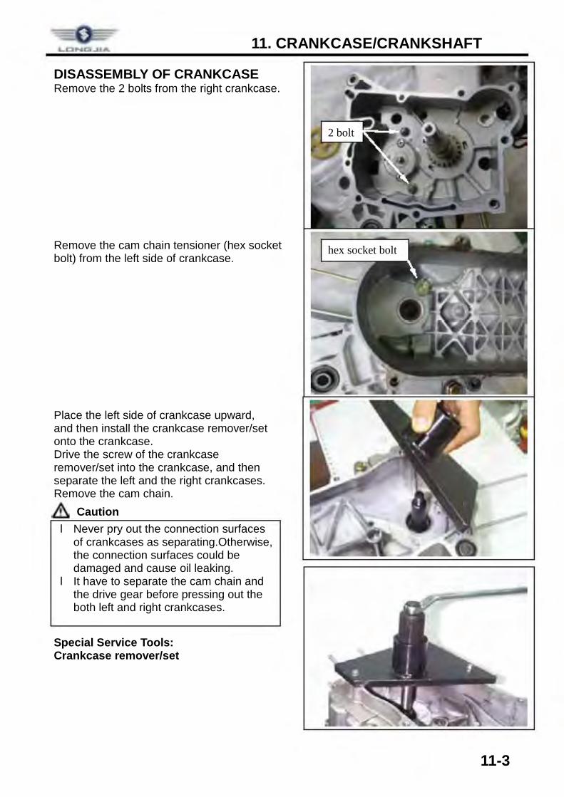
DISASSEMBLY OF CRANKCASE Remove the 2 bolts from the right crankcase. Remove the cam chain tensioner (hex socket bolt) from the left side of crankcase. Place the left side of crankcase upward, and then install the crankcase remover/set onto the crankcase. Drive the screw of the crankcase remover/set into the crankcase, and then separate the left and the right crankcases. Remove the cam chain.
Caution Special Service Tools: Crankcase remover/set
l Never pry out the connection surfaces of crankcases as separating.Otherwise, the connection surfaces could be damaged and cause oil leaking.
l It have to separate the cam chain and the drive gear before pressing out the both left and right crankcases.
2 bolt
hex socket bolt
11. CRANKCASE/CRANKSHAFT
11-4
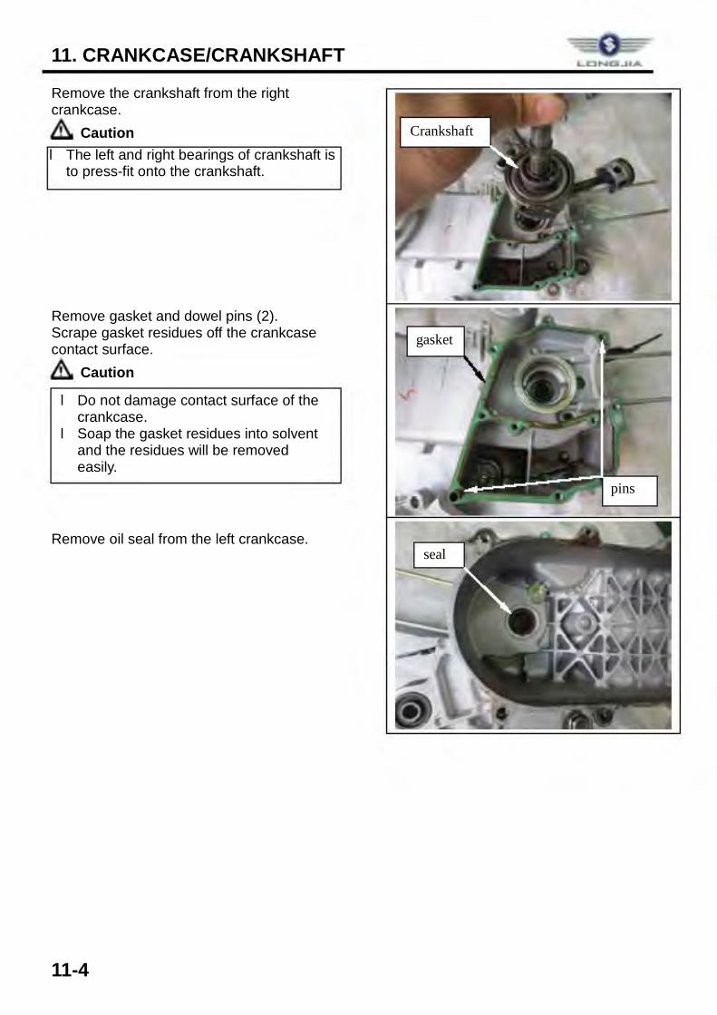
Remove the crankshaft from the right crankcase.
Caution Remove gasket and dowel pins (2). Scrape gasket residues off the crankcase contact surface.
Caution Remove oil seal from the left crankcase.
l Do not damage contact surface of the crankcase.
l Soap the gasket residues into solvent and the residues will be removed easily.
l The left and right bearings of crankshaft is to press-fit onto the crankshaft.
Crankshaft
gasket
pins
seal
11. CRANKCASE/CRANKSHAFT
11-5
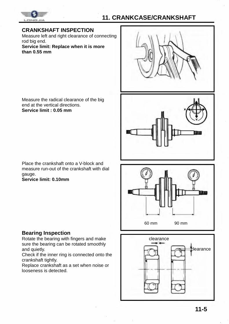
CRANKSHAFT INSPECTION Measure left and right clearance of connecting rod big end. Service limit: Replace when it is more than 0.55 mm Measure the radical clearance of the big end at the vertical directions. Service limit : 0.05 mm Place the crankshaft onto a V-block and measure run-out of the crankshaft with dial gauge. Service limit: 0.10mm Bearing Inspection Rotate the bearing with fingers and make sure the bearing can be rotated smoothly and quietly. Check if the inner ring is connected onto the crankshaft tightly. Replace crankshaft as a set when noise or looseness is detected.
60 mm 90 mm
clearance
clearance
11. CRANKCASE/CRANKSHAFT
11-6
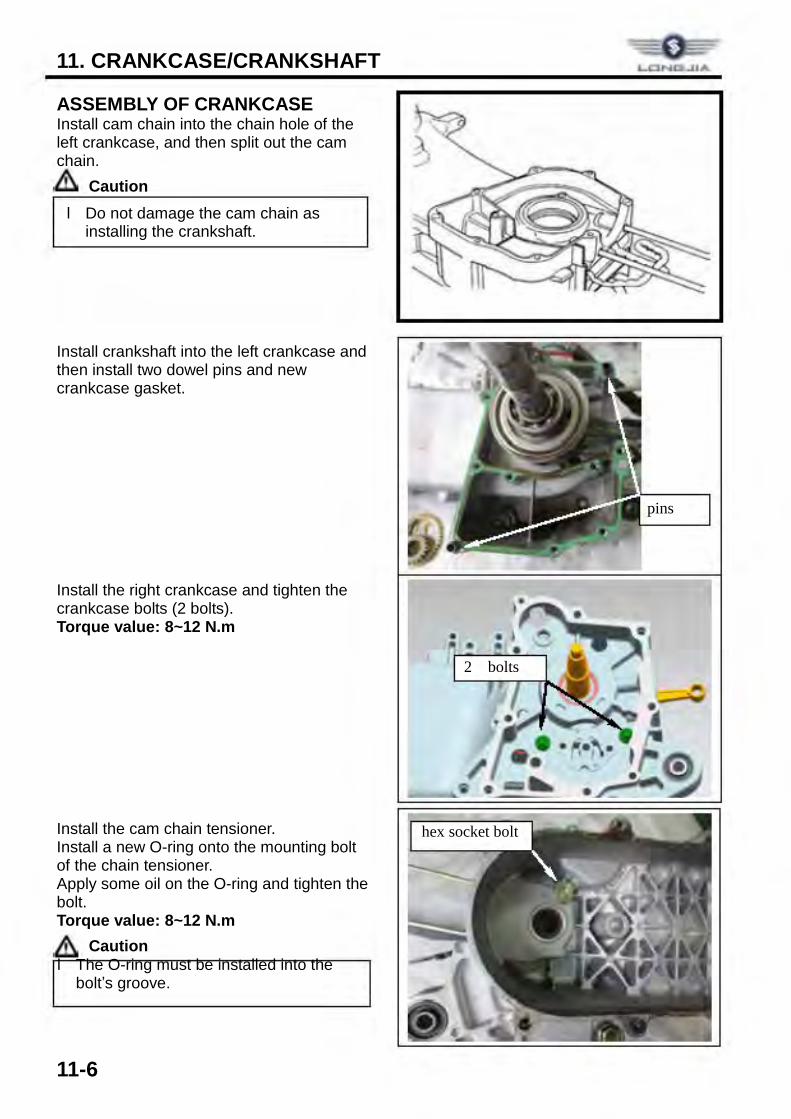
ASSEMBLY OF CRANKCASE Install cam chain into the chain hole of the left crankcase, and then split out the cam chain.
Caution Install crankshaft into the left crankcase and then install two dowel pins and new crankcase gasket. Install the right crankcase and tighten the crankcase bolts (2 bolts). Torque value: 8~12 N.m Install the cam chain tensioner. Install a new O-ring onto the mounting bolt of the chain tensioner. Apply some oil on the O-ring and tighten the bolt. Torque value: 8~12 N.m
Caution
l Do not damage the cam chain as installing the crankshaft.
l The O-ring must be installed into the bolt’s groove.
pins
2 bolts
hex socket bolt
LCING..IIA
• n •
11. CRANKCASE/CRANKSHAFT
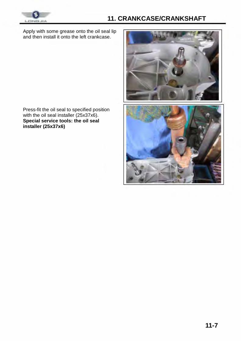
11-7
Apply with some grease onto the oil seal lip and then install it onto the left crankcase. Press-fit the oil seal to specified position with the oil seal installer (25x37x6). Special service tools: the oil seal installer (25x37x6)
12. STARTING CLUTCH
12-1
COMPONENT STRUCTURE ............. 12-1 REMOVAL ......................................... 12-2
INSTALLATION .................................. 12-2
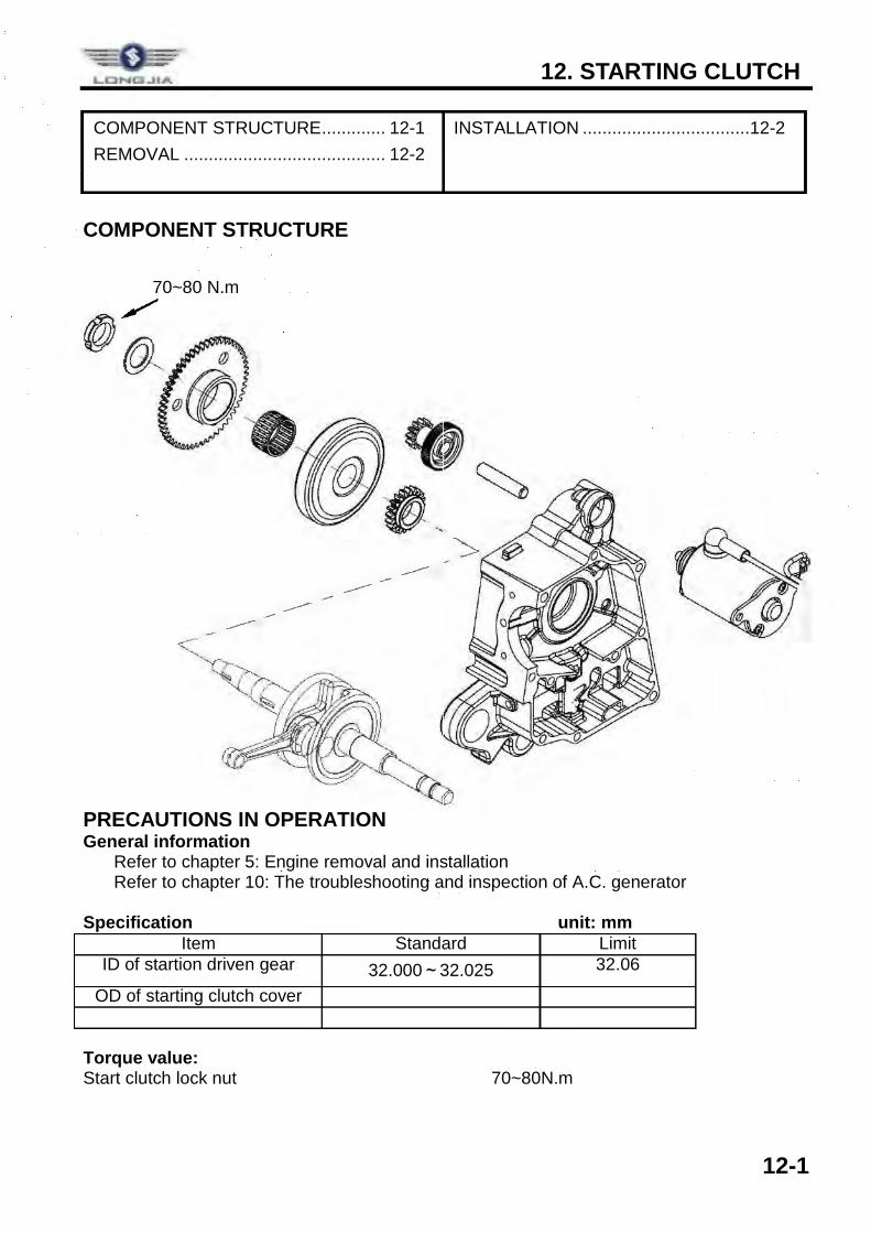
COMPONENT STRUCTURE PRECAUTIONS IN OPERATION General information ü Refer to chapter 5: Engine removal and installation ü Refer to chapter 10: The troubleshooting and inspection of A.C. generator Specification unit: mm
Item Standard Limit ID of startion driven gear 32.000~32.025 32.06
OD of starting clutch cover
Torque value: Start clutch lock nut 70~80N.m
70~80 N.m
LOP,U:l...i lA
I I I
12. STARTING CLUTCH
12-2
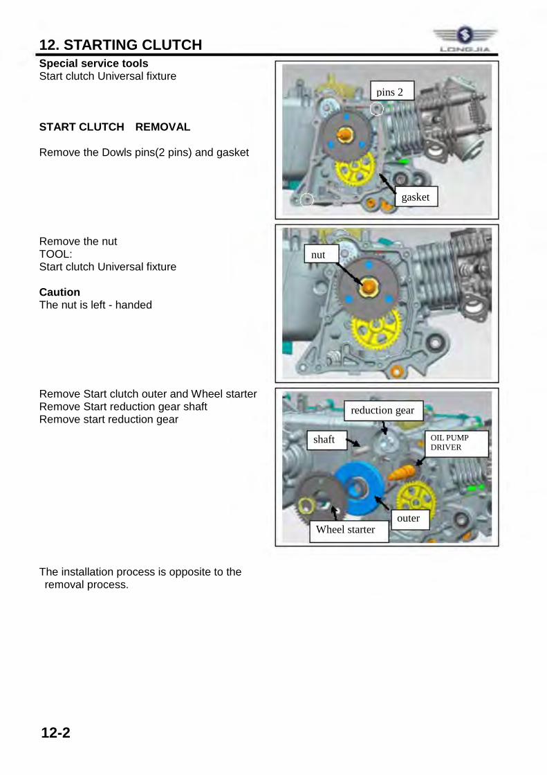
Special service tools Start clutch Universal fixture START CLUTCH REMOVAL
Remove the Dowls pins(2 pins) and gasket Remove the nut TOOL: Start clutch Universal fixture Caution The nut is left - handed Remove Start clutch outer and Wheel starter Remove Start reduction gear shaft Remove start reduction gear The installation process is opposite to the removal process.
pins 2
gasket
nut
outer Wheel starter
reduction gear
shaft OIL PUMP DRIVER GEAR