SERVICE MANUAL FOR 6700, 7000, 8000 & 9000 … manual for 6700, 7000, 8000 & 9000 series air...
26
SERVICE MANUAL FOR 6700, 7000, 8000 & 9000 SERIES AIR CONDITIONERS (MECHANICAL CONTROLS ONLY) FOR WALL MOUNT THERMOSTATS AND LOW VOLTAGE CONTROL CIRCUITS, REFER TO THEIR APPROPRIATE MANUALS FOR ELECTRICAL CHECKOUTS ON DELTA T AND DELTA TX AIR CONDITIONERS, REFER TO MANUAL R-332 (2-86)
Transcript of SERVICE MANUAL FOR 6700, 7000, 8000 & 9000 … manual for 6700, 7000, 8000 & 9000 series air...
SERVICE MANUAL
FOR
6700, 7000, 8000 & 9000 SERIES
AIR CONDITIONERS
(MECHANICAL CONTROLS ONLY)
FOR WALL MOUNT THERMOSTATS AND LOW VOLTAGE CONTROLCIRCUITS, REFER TO THEIR APPROPRIATE MANUALS
FOR ELECTRICAL CHECKOUTS ON DELTA T AND DELTA TXAIR CONDITIONERS, REFER TO MANUAL R-332 (2-86)

PREFACE
This service manual is primarily intended for the use ofqualified individuals specially trained and experienced in theservice of this type of equipment and related systemcomponents.
Installation and service personnel are required by some states,counties or cities to be licensed. Persons not qualified shallnot attempt to service this equipment or interpret this servicemanual.
SCOPE
This is not a basic refrigeration and air conditioning manualand does not therefore, cover the principles of refrigeration orair conditioning. The user of this manual should havealready accomplished a thorough study of refrigeration andair conditioning.
WARNING
Improper installation may damage equipment, can createa hazard and will void the warranty.
The use of components not tested in combination withthese units will void the warranty, may make theequipment in violation of state codes, may create a hazardand may ruin the equipment.
!WARNING - SHOCK HAZARD!
TO PREVENT THE POSSIBILITY OF SEVEREPERSONAL INJURY, DEATH OR EQUIPMENTDAMAGE DUE TO ELECTRICAL SHOCK, ALWAYSBE SURE THE POWER SUPPLY TO THE APPLIANCEIS DISCONNECTED BEFORE DOING ANY WORK ONTHE APPLIANCE. THIS CAN NORMALLY BEACCOMPLISHED BY SWITCHING THE BREAKERFOR THE AIR CONDITIONER TO OFF,DISCONNECTING ALL EXTERNAL ELECTRICALCONNECTIONS AND CORDS, SWITCHING ONBOARD ELECTRICAL GENERATORS ANDINVERTORS TO OFF, AND REMOVING THE CABLEFROM EACH POSITIVE TERMINAL ON ALLSTORAGE AND STARTING BATTERIES.
DANGER
SOME DIAGNOSTIC TESTING MAY BE DONE ONENERGIZED CIRCUITS. ELECTRICAL SHOCK CANOCCUR IF NOT TESTED PROPERLY. TESTING TOBE DONE BY QUALIFIED TECHNICIANS ONLY.
6757-7201SERVICE TEST DEVICE
This test device is an invaluable aid in quickly diagnosing repairsto all RV Products roof top air conditioners produced after 1979.

TABLE OF CONTENTS
Basic Components and Their FunctionsRefrigeration System Diagram
I. Refrigeration Circuit . . . . . . . . . . . . . . . . . . . . . . . . . . . . . . . . . . . . . . . . . . 5
II. Air Handling Circuits . . . . . . . . . . . . . . . . . . . . . . . . . . . . . . . . . . . . . . . . . 6
III. Electric Power Circuits . . . . . . . . . . . . . . . . . . . . . . . . . . . . . . . . . . . . . . . . 6
IV. Tools And Equipment . . . . . . . . . . . . . . . . . . . . . . . . . . . . . . . . . . . . . . . . . 10
V. Service Problems And Their Solutions . . . . . . . . . . . . . . . . . . . . . . . . . . . . 13
VI. Typical Wiring Diagrams . . . . . . . . . . . . . . . . . . . . . . . . . . . . . . . . . . . . . . 20
QUICK DIAGNOSIS CHART
Note: This charge represents problems with units having mechanical controls - if the air conditioneris equipped with a wall thermostat, please refer to the appropriate manual.
Problem Possible Causes Ref. Page Number
Fan And Compressor Will Not Run No Power 115V 14Selector Switch 14
Fan Will Not Run Selector Switch 17Fan Run Capacitor 17Motor 17Wiring (Mis-wired) 20-21
Compressor Will Not Run Selector Switch 15Thermostat 15Low Voltage 15Overload 15Compressor 15Wiring (Mis-wired) 20-21PTCR or Potential Relay 16-17Start Capacitor 20-21Run Capacitor
Cooling Performance 19

4
BASIC COMPONENTS AND THEIR FUNCTIONSREFRIGERATION SYSTEM DIAGRAM
DISCHARGELINE SUCTION
LINE
COMP.
CONDENSER FAN
FANMOTOR
EVAPORATORBLOWER
EVAPORATOR
CONDENSER COIL
HIGH SIDE LOW SIDE

5
The purpose of this part of the Service Manual is to acquaintthe Service Technician with the system components so thatwhen he has a problem, he can intelligently analyze andisolate the problem and efficiently correct it.
BASIC COMPONENTS ANDTHEIR FUNCTIONS
I. REFRIGERANT CIRCUIT
1. Refrigerant Charge
The systems covered by this service manual all use arefrigerant called monochlorodifluoromethane (better knownas R-22).
We know that R-22 is not a deadly gas because many of ushave breathed it many times and we are still living. But, noone has said that R-22 is completely safe to breathe; so, awise service technician will always keep a work space wellventilated if R-22 can escape into the air. IF R-22 COMESIN CONTACT WITH ANY OPEN FLAME, PHOSGENEGAS IS CREATED AND ONE SHOULD AVOIDBREATHING THE FUMES.
The temperature at which R-22 changes to toxic gases andacids varies with the amount or concentration of waterpresent i.e. the greater the concentration of water, the lowerthe temperature and vice versa. High temperatures normallyexist inside a refrigeration circuit, so we must keep the circuitas absolutely dry as possible to prevent the formation ofdestructive acids.
Liquid R-22 in the atmosphere will always be at about -41°. Therefore, always wear safety glasses when working with R-22.
Again unburned R-22 is not a deadly gas, so by usingreasonable safety precautions, the service technician will notbe hurt by it.
In addition to being almost non-toxic, R-22 is non-flammable, non-explosive, non-corrosive and miscible(mixable) with oil. It also has a rather high latent heat value. This means that is must absorb a large amount of heat per lb.to vaporize or change from a liquid to a vapor; and it mustgive up a large amount of heat per lb. to condense or changefrom a vapor to a liquid.
2. High and Low Sides
It is customary for air conditioning technicians to use theterms high side and low side. In doing so, we refer to theparts of the refrigeration circuit which, when the system isrunning, contain high pressure refrigerant (high side) andlow pressure refrigerant (low side). The high side of these
systems exists from the discharge port of the compressor tothe cap tube. The low side is from the cap tube to thecompressor cylinders. The dividing points then are the captube and compressor cylinders.
The high side pressure is also referred to as head pressure orcondensing pressure, and the low side pressure is alsoreferred to as suction pressure or evaporator pressure.
It is impossible to state the exact pressures that will exist inthe high side or low side because those pressures will bothvary with different temperature and humidity conditions bothinside and outside the recreational vehicle.
3. Capillary Tube (Cap Tube)
The refrigerant enters the cap tube from the condenser as awarm high pressure liquid. As the refrigerant flows throughthe small diameter cap tube, the pressure drops rather rapidly. As the pressure drops, a tiny amount of the liquid refrigerantwill vaporize. This vaporization requires heat which mustcome from the liquid refrigerant itself - thus the liquidtemperature is constantly lowered as it passes through the captube. As the refrigerant leaves the cap tube, it is still mostlyliquid; however, a small portion has changed to a vaporcalled flash gas. When the liquid refrigerant passes from thecap tube to the evaporator, it is at low side pressure and willtherefore, vaporize at low temperature as it picks up heatfrom the air being conditioned.
4. Evaporator Coil
The purpose of the finned evaporator coil is to transfer theheat from the warm and moist indoor air to the cold lowpressure refrigerant.
As the heat leaves the air, the air temperature drops and someof the moisture in the air condenses from a vapor to a liquid. The liquid water (condensate) is drained onto the roof of therecreational vehicle. As the heat enters the refrigerant in theevaporator, it causes the refrigerant to evaporate (changefrom a liquid to a vapor). Thus the name – evaporator.
The refrigerant remains at nearly constant temperature(called evaporator temperature or low side saturationtemperature) in the evaporator as long as there are both liquidand vapor together. However, near the outlet of theevaporator coil, all of the liquid has boiled (evaporated) awayand from there on the temperature of the vapor rises (thevapor becomes superheated). It is necessary that the vaporbecome superheated because it passes through the suctionline to the compressor and the compressor can only pumpsuperheated vapor – any vapor (which might be present if thevapor were not superheated) could cause serious mechanicaldamage to the compressor.

6
5. Suction Line
The suction line is the tube which carries the superheatedvapor refrigerant from the evaporator to the compressor.
6. Compressor
The compressor is called a hermetic compressor which meansthat it is completely sealed (welded together). It is, therefore,not internally field serviceable. Inside the compressorhousing are basically:
a) an electric motor which drives the compressor,
b) a pump which is designed to pump superheatedvapor only,
c) a supply of special refrigeration oil. A small portionof the oil will circulate out through the system withthe refrigerant, but will constantly return to thecompressor with the refrigerant, so the compressorwill not run out of oil.
7. Discharge Line
The discharge line carries the refrigerant out of thecompressor and to the condenser coil. Remember that as therefrigerant entered the compressor, it was superheated vapor. The refrigerant enters the compressor, where more heat isadded and is compressed into a smaller space. Therefrigerant, therefore, leaves the compressor highlysuperheated – so if the discharge line is hot to the touch(burns), don’t be surprised – it should be.
8. Condenser Coil
The purpose of the finned condenser coil is to transfer heatfrom the high pressure refrigerant to the warm outdoor air. As the outdoor air passes over the coil, the heat transfer willcause the air temperature to rise. Thus the condenserdischarge air will be several degrees warmer than thecondenser entering air.
As the refrigerant passes through the first few tubes of thecondenser, its temperature will be lowered or it will be de-superheated. After the refrigerant is de-superheated, it willbegin to condense or change from a vapor to a liquid and willremain at a nearly constant temperature throughout almost allof the remainder of the coil. This temperature is called the condensing temperature or high side saturation temperature and will always be higher than the condenser entering airtemperature.
Near the bottom of the condenser, the refrigerant will all becondensed to a liquid and from there on its temperature willdrop to more nearly the temperature of the outdoor air. Afterthe temperature of the refrigerant drops below condensing or
saturation temperature, we call its condition sub-cooledliquid.
During all of the three processes in the condenser (de-superheating, condensing, sub-cooling), the refrigerant givesup heat; but most of the heat is given up during thecondensing process.
II. AIR HANDLING CIRCUITS
1. Motors and Fans
One motor turns both the condenser fan blade and evaporatorair blower. The condenser (outdoor) fan is an axial flow(propeller) type and the evaporator (indoor) fan or blower is acentrifugal (squirrel cage) type.
2. Filters
The filters should always be in place when the system isrunning. More important than their purpose of cleaning theair in the living space is the protection the filters give theevaporator coil. Without filters, a wet evaporator coil willquickly stop up so that adequate air cannot pass through it. Filters must be installed to completely fill the filter rack sothat no air can flow around them or by-pass them and carrydust, lint, etc. to the evaporator. To clean an evaporator thathas not been properly protected by its filter, the entire unitmust be removed from the recreational vehicle and the coilcleaned with special detergent and water.
III. ELECTRIC POWER CIRCUITS
1. Safety
Voltage (electrical pressure), whether high or low, will nothurt you. It is the current through vital parts of your bodythat does the damage, and under the right conditions, 115volts (domestic USA) is plenty to drive a deadly dose ofcurrent (amperes) through your body.
Another imminent danger from electric shocks in addition toelectrocution is reaction. An electrical shock causesuncontrollable muscular contractions which can cause furtherinjuries.
Remember that electricity can be very dangerous, but you cansafely work with it. In order to be safe, you must know whatyou are doing. You must work deliberately and carefully. You must think safety before each move.
THINK SAFETY
2. Power Supply - from Commercial Utility
1) Wire Size

7
The power supply to the air conditioner must be wired through a circuit breaker or time delay fuse. The powersupply must be 20 amperes and 12 AWG wire minimum. Any size
larger at any time may be used and should be used if thelength of the wire is over 32 feet.
2) Color Code
The electric power from the electric service panel should bedelivered through a 3 conductor cable and the ServiceTechnician should check to be sure the color code is correct. The electrician probably installed the cable with the colorsaccording to code, but don’t bet your life on it.
a) The wire with black insulation is the hotwire and there should be 115 volts(domestic USA) between it and either of theother wires. All switches, fuses, circuitbreakers, disconnects, etc. should be in thisline.
b) The wire with the white insulation is theneutral. There should be 115 volts(domestic USA) between the neutral and thehot (black) wire, but there should be 0 voltsbetween the neutral and the ground (thegreen wire or the frame of the airconditioner). There must be no switches,fuses, disconnects, etc. of any kind in theneutral wire.
c) The third wire may be covered with greeninsulation or it may be a bare metal wire. Itis the ground wire. There must be 115 volts(domestic USA) between this wire and thehot (black) wire and 0 volts between it andthe neutral (white) wire. The ground wiremust be securely fastened to the airconditioner cabinet. A ground screw isprovided for this purpose.
3) Voltage
The voltage (electrical pressure) at the unit should be 115 volts (domestic USA) and all electrical components willperform best at the correct voltage. However, the voltage willvary and the air conditioning system will performsatisfactorily within plus or minus 10% of the rated (115)voltage (domestic USA). Therefore, the voltage has to bebetween 103.5 volts and 126.5 volts.
3. Power Supply - Generated by on-board motorgenerator
If the power supply for the recreational vehicle is supplied by
an on-board motor generator, its wiring may be identical tothe commercial power described above.
There are, however, some motor generators on which both thecurrent carrying leads are insulated from the ground. That isto say; there is no grounded neutral, so there will be 115 volts
(domestic USA) between the black and white leads, but therewill be 0 volts between either lead and ground.
WARNING: The service technician must keep in mindwhen checking to make sure that the power is turned off. Check only between the hot (black) lead and the neutral(white) lead.
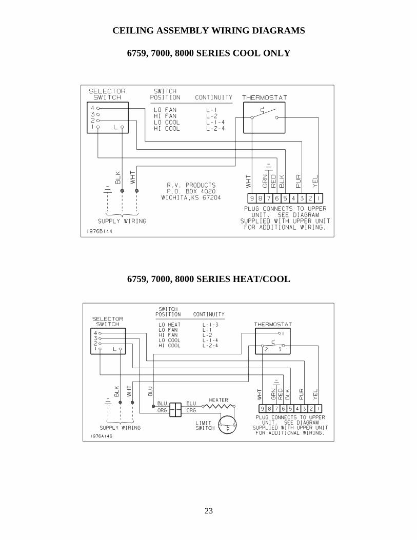
4. Selector Switch - Free Delivery Ceiling Assemblies
The selector switch is mounted on the left side of the interiorceiling assembly. The selector switch allows the unit to beoperated on high to low blower only, or high to low blowerwith compressor operation for cooling. On heating andcooling models, the selector switch can also switch in theelectric heater at low blower operation only.
To check the selector switch, remove wires from the terminalsand rotate the switch to the proper position and readcontinuity as follows:
Terminals Switch Position
L-1-3 Lo HeatL-1 Lo FanL-2 Hi FanL-1-4 Lo CoolL-2-4 Hi Cool
* If you do not wish to remove the wires from each terminal,disconnect the 9 pin plug from the a/c unit.
5. Thermostat (Mechanical Rotary)
The thermostat (temperature controller) is mounted on theright side of the interior ceiling assembly. The thermostatcontrols the on-off cycle of the compressor when the selectorswitch is in the cooling position and on heating and coolingmodels, the on-off cycle of the electric heater when theselector switch is in the heating position. The thermostat isactuated by sensing the temperature of the return air throughthe vent where the bulb is located. Terminal continuityshould make and break if ambient air temperature is between65 and 90 degrees F.
6. Compressor Motor
The compressor motor is located inside the hermeticcompressor housing and therefore not accessible for service orvisual observation in the field. However, the motor winding

8
condition can be analyzed by using an ohm meter. Be sure toremove all the leads from the compressor terminals beforemaking this check.
1) If the resistance between any two terminals is 0ohms, the motor windings are shorted.
2) If the resistance between any terminal and thecompressor housing is anything but infinity, thewinding is grounded.
3) If the resistance between any two terminals isinfinity, the winding is open.
On a good compressor, the highest resistance will be betweenthe R (run) and S (start) terminals. The lowest resistance willbe between the C (common) and R (run) terminals. Theintermediate resistance will be between the C (common) and S (start) terminals. Notice that compressors have theidentification of the terminals marked on either the terminalcover or on the compressor housing.
7. Overload Switch
Mounted on the outside of the compressor housing is a twoterminal overload switch. Note: We have a few models withinternal overloads that are non-serviceable. The switch isconnected in series with the common terminal, so if theswitch opens, it will cut the power to the compressor motor. The switch will open as the result of either or both of twoconditions that could be harmful to the compressor.
1) High Amperes (Current)
The switch contains a heater which increases in temperatureas the current increases. The higher temperature warps theswitch and will cause it to open before the windings reach adangerous temperature.
2) High Temperature (Thermal)
The switch is clamped tightly against the compressor housingand located close to the windings. Therefore, as the windingsreach a higher temperature, it takes less current to cause theswitch to open.
As can be seen, the switch is always affected by acombination of current to the compressor and windingtemperature.
8. Fan Motor
The air conditioning unit has one double end shaft fan motor. On one shaft end is mounted a centrifugal or squirrel cageblower which draws air (return air) out of the recreationalvehicle and blows the conditioned air down into therecreational vehicle. On the other end is mounted an axialflow or propellor type fan which circulates outdoor air
through the condenser coil.
* Some models use a squirrel cage on both ends of the motor.
An important step in installing a replacement fan motor is tocheck the direction of rotation before it is installed. On allmodels, the condenser fan pulls the air through the coil.
Fan Motor Check Procedure
If a fan motor refuses to perform properly, it can be checkedin the following manner:
9. Be sure the motor leads are connected to the properpoints –a) The black wire from the motor connects to a
black wire inside a wire nut then the blackwire connects through the disconnect plugto the selector switch. The red wire fromthe motor connects to a red wire in a wirenut then the red wire connects through thedisconnect plug to the selector switch.
b) The white wire from the motor connects tothe fan capacitor or a white wire in a wirenut then the white wire connects throughthe disconnect plug to the thermostat.
c) The brown wires from the motor connect tothe fan capacitor.
2. To check the motor winding resistance carefully,check the resistance between each of the wires andground (preferably a copper refrigerant tube for agood connection). These readings must be infinity. Any continuity means the windings are grounded.
If there is a reading of 0 between any two leads, the motor is shorted and is no good. If there is a reading of infinity (no meter reading at all) between any twoleads, the winding is open and the motor is no good.
Note: A motor with 2 brown leads will have an O reading between 1 brown wire and eitherthe black or white wire.

9
CAPACITOR
OHM METER
HIGH LOW
OK
Indicator sweeps back and forthas shown above. Capacitor is good.
HIGH LOWOPEN
Indicator shows no movement.Needle stays to the left side. If needle
shows no movement after reversing the leads, the capacitor is open.
HIGH LOWSHORT
Indicator moves to the right sideof the scale and stays there
(indicating a completed circuit).The capacitor is shorted.
9. Run Capacitors
The purpose of the run capacitors is to give the motorsstarting torque and to maintain high power factor during running. The run capacitors are always connected betweenthe start and run or main terminals of the motor.
On some older models, one of the terminals of the runcapacitors will have a red dot (the identified terminal). Theidentified terminal should always be connected to the run ormain terminal of the motor and to the neutral line.
CAPACITORS
Capacitor Check
There are several capacitor test devices available. The ohmmeter is one of them. The ohm meter cannot verify acapacitors MFD (microfarrad) value. However, the followingprocedures will show you how to use an ohm meter todetermine if the capacitor is good, open, shorted or grounded.
Before testing any capacitor, always perform the followingprocedure:
* This test must be done with a analog type meter.
a) Disconnect all electrical power to the air conditioner.
b) Discharge the capacitor with a 20,000 ohm (approx.3 watt) resistor or larger.
c) You may discharge capacitors with a standard voltmeter if you use a scale over 500 volts and touch theleads (one lead to each side of the capacitor). Thevolt meter will discharge the capacitor.
d) Identify and disconnect the wiring from thecapacitor.
e) Set and zero the ohm meter on the “highest” scale.
When testing for a good, open or shorted capacitor,perform the following checks: Place the ohm meterleads across the capacitor terminals (one lead oneach terminal) and perform a continuity test. Thenobserve the action of the meter needle or indicator. Reverse the leads and test again. The result shouldbe the same. Note: If the capacitor had not beenproperly discharged, a false reading could beindicated on the first test. Always test several times(reversing the leads with each test). This will verifythe capacitors condition.
Good Capacitor
If the capacitor is good, the indicator will move from infinity(the left side), towards zero ohms and slowly return back toinfinity. Reverse the leads and test again. The result shouldbe the same.
Open Capacitor
If the capacitor is open, the indicator will show no deflectionor movement. Reverse the leads and test again. If there is noindicator movement on the second test, the capacitor is open. Open capacitors are defective and must be replaced.
Shorted Capacitor
If the capacitor is shorted, the indicator will move towards and sometimes hit zeroohms, and will stay there. This indicates a completed circuit through the inside ofthe capacitor (shorted). Shorted capacitors are defective and must be replaced.

10
Grounded Capacitor
When testing for a grounded capacitor, perform a continuitycheck between each terminal on the capacitor and the baremetal of the capacitor case. Any indication of a circuit(constant resistance) from either terminal to case, indicates agrounded capacitor. Grounded capacitors are defective andmust be replaced.
Indicator moves to the right side ofthe scale and stays there
(indicating a completed circuit).The capacitor is grounded.
10. Start Capacitor
Most models use a start capacitor and a start relay to give thecompressor high starting torque. The compressor will,therefore, start against normal pressure difference (headpressure minus suction pressure) even when shut down for ashort period of time. The start relay will disconnect the startcapacitor when the motor reaches approximately 75%running speed.
11. (A) Start (Potential) Relay
The start relay consists of –
1) Normally closed contacts internally betweenterminals #1 and #2 which switch in the startcapacitor in parallel to the run capacitor during shutdown and then switch out the start capacitor whenthe motor reaches approximately 75% normalrunning speed.
2) A high voltage coil internally between terminals #5and #2 to actuate the contacts. The coil is too weakon line voltage to actuate the contacts, but it is
connected in series with the start winding and it getsthe generated voltage of the start winding portion ofthe compressor motor. This generated voltage ismuch higher than line voltage and varies with thespeed of the motor. Therefore, since the relay isdesigned to open the contacts at 75% of normalrunning voltage (measured between terminals #5 and#2), the contacts will open (thus disconnect the startcapacitor) at approximately 75% of normal runningspeed.
11. (B) Positive Temperature Coefficient Resistor(Commonly Known As PTCR StartDevice)
The resistor acts like a potential relay in that it takes the startcapacitor out of the start circuit, but uses resistance ofelectrical flow (back EMF from compressor) instead ofopening a set of contacts. The service person should be carefulhandling the resistors. They will be hot during operation (upto 160 degrees F). The air conditioner needs to be off for 3-5minutes during cycle time and when servicing to let theresistor cool down.
12. Heating Element
The heating element is a resistance heater of 1600 watts (5600BTUH) capacity and is connected across the line when theselector is set for heating and the thermostat is calling for heat. The current draw of the heater (element only) will be 13.3amperes at 120 volts (domestic USA models).
13. Limit Switch
The limit switch is a safety switch and is mounted in theheating element frame. It will open and break the circuit ontemperature rise in case the air flow through the heaterbecomes low enough to cause the heater to overheat.
IV. TOOLS AND EQUIPMENT
In order to service the equipment covered by this ServiceManual, a technician will need all the common mechanicstools such as wrenches, screwdrivers, hammers, etc.
In addition to the common mechanics tools, in order to dorefrigeration and electrical work, he will need special tools andequipment such as:
1. Ammeter2. Ohm Meter3. Volt Meter4. Refrigerant Recovery Equipment5. Charging Cylinder6. Vacuum Pump7. Vacuum Gauge8. Leak Detector9. Brazing Equipment10. Gauge Manifold
CAPACITOR
OHM METER
HIGH LOWGROUNDED

11
1. Ammeter And Its Use
An ammeter is an instrument for measuring electric current. Current electricity is actually electrons moving from one atomto another through a conductor. In order to intelligently useelectricity, we must have a measurement of a quantity ofelectrons.
The instrument we use to measure the number of amperes iscalled an ammeter. These instruments have snap-aroundjaws that will allow you to read the current through a wirewithout detaching the wire from the system. Always buy anenergizer with the instrument so that you can accurately readlow current circuits. These meters also have volt meter andohm meter attachments so they are an excellent multi-purposemeter. NO TECHNICIAN SHOULD EVER ATTEMPT ASERVICE CALL WITHOUT ONE.
2. Ohm Meter And Its Use
An ohm meter or resistance meter indicates the resistance of acircuit to current flow. Just as every water pipe or hose has aresistance to water flow or every air duct has resistance to airflow, so does every wire have resistance to the flow of electriccurrent. There is no such thing as a conductor with zeroresistance to electron flow although sometimes we will bemeasuring the resistance of a conductor and find it so lowthat we cannot detect any resistance; so we call the resistancezero. What we mean is that the resistance is so low that wecan’t find it. The amount of resistance or holding back forceof the wire or conductor depends on:
a) The material the conductor is made of; silver, copperand aluminum are good conductors. This means thatin any given size wire, these materials will have lowresistance. Silver has the lowest resistance, but itsprice is too high, so we use copper.
b) The diameter of the wire. The longer the wire, thegreater the resistance because there is more metal tocarry the current.
c) The length of the wire. The longer the wire, thegreater the resistance. In fact, the resistance of anywire varies in direct ratio with its length.
d) The temperature of the conductor. The resistance ofmost - but not all - conductors increases as thetemperature of the conductor rises. Hence, the resistance of the filament of a light bulb is rather lowwhen it is turned off and cooled down; but when thepower is turned on, the filament temperatureincreases until it glows and the resistance increases.
Resistance to electron flow is measured in units called ohms. An ohm is actually the amount of resistance that will hold thecurrent down to one ampere (one coulomb of electrons per
second) if there is one volt of pressure.
An ohm meter is really a resistance meter that is calibrated inohms. The ohm meter has its own power source, a small drycell, which forces a small amount of current through aconductor via the meter probes. The meter must be calibratedto read 0 ohms when the probes are touched together each timeit is used because as the dry cell loses its charge, the meter willget out of calibration.
If the probes of an ohm meter are attached to the terminals of aclosed switch, the meter will read 0. This means that there isvirtually no resistance to current flow through the switch. Now, if the switch is turned off, the contacts will be open andthere will be very high resistance. In fact, the resistance is sohigh it is an infinite number of ohms so we call this readinginfinity.
With the switch open, there is not a continuous conductorthrough it so we say there is no continuity. If the ohm meterreads anything other than infinity, we say we do havecontinuity. As can be seen from the above example, an ohmmeter is a good instrument for checking to see if the contactsof a switch, thermostat, relay, overload, etc. are closingproperly or creating continuity.
The previous examples show two conditions that can bedetected by an ohm meter; (1) a closed, 0 resistance conductorand (2) an open circuit which reads infinity or no continuity. Now let’s consider something in between – the windings of acompressor. If we attach the ohm meter probes to the commonand run terminals of the compressor, we can read theresistance of the main or run winding. The winding is a solidand continuous copper wire so there will be continuity throughit; but instead of 0 ohms, as there was through the closedswitch, this winding is of such small wire and so long thatthere is resistance. Now let’s attach the probes to the commonand start terminals to get the resistance of the start of phasewinding. Since this winding is made of even smaller andlonger wire, its resistance will be greater than the mainwinding. Now let’s attach the probes to the start and runterminals to read the resistance through both windings. Thisreading is the same number of ohms as the total of the twoprevious readings.
If the reading between any two terminals is infinity, we candetermine that the winding is open – the wire is broken orburned in two. If the reading between any two terminals is 0ohms, the insulation is burned off the winding and we candetermine that the compressor motor is shorted. If the readingbetween any terminal and the compressor housing is anythingexcept infinity, we can determine that the compressor motor isgrounded. An open, shorted or grounded compressor must bereplaced. The fan motor windings can be checked by the samemethod as the compressor motor winding. The only differencebeing that the windings are made of smaller gauge wire andthe resistance will be higher. The fan motor has no push on

12
terminals, but we know by referring to the wiring diagram,that the black wire is the common terminal, the red wire isthe start terminal and the white wire is the run terminal.
Notice that when we are using an ohm meter, the power mustbe turned off. It is also important to disconnect all wiresfrom a conductor being checked with an ohm meter toprevent any chance of feedback.
An Ammeter is an essential instrument to have and use, andis a real bargain because it is three instruments in one.
3. Volt Meter And Its Use
A volt meter measures the amount of electrical pressure in anelectrical conductor just as a tire gauge measures the amountof air pressure in an automobile tire. If we attach one voltmeter probe to the hot line and the other probe to the neutralline of a standard circuit, the meter reading will be theelectromotive (electron moving) force or pressure differencebetween the two lines. This is the amount of pressure wehave available to push electricity (electrons) through the lightbulbs to make the motors turn, etc. In the above example, weshould find approximately 115 volts (domestic USA models)or units of electrical pressure. Remember, a volt meteralways registers the voltage pressure difference between twopoints.
CAUTION
A volt meter is used on live circuits so use extreme care. THINK SAFETY!
4. Refrigerant Recovery Equipment
The Environmental Protection Agency has implemented strictregulations on refrigerant handling and refrigerant recoveryequipment.
Check with your local EPA office regarding what type ofcertification you must have to open or work on the refrigerantsealed system.
In accordance to the Clean Air Act passed in 1980:
1. There shall be no venting of refrigerant into theatmosphere after July 1, 1992.
2. All recovery equipment must meet EPA standards(check with your local office).
3. Technician Certification deadline was November 14, 1993.
5. Charging Equipment
The amount of charge in any refrigerant system must be kept
accurate to within a fraction of an ounce to prevent damage tothe compressor and insure proper performance. Systems mustnot be charged to a certain amperage pull. They must not becharged to certain suction line temperature.
The recommended field instrument for charging the rightamount of R-22 into the system is either:
1. An electronic scale made especially for charging a/csystems of critical charge. (Note: The charge mustnot be weighed in with inaccurate bathroom scales,or,
2. A Dial-A-Charge of 5 lb. capacity. Do not use theDial-A-Charge 10 lb. capacity or any other chargingcylinder on which the graduations of the scale aresuch that the instrument cannot be read accurately.
Follow the charging cylinder manufacturer’s instructionscarefully.
6. Vacuum Pump
It has long been recognized that the worst enemy of arefrigeration system is water. R-22 (and other refrigerants)will break down and change to strong acids at elevatedtemperatures in the presence of water. The greater theconcentration of water, the lower the temperature at which therefrigerant will break down. The only way to remove thewater from a system to a satisfactory level is to vaporize it anddraw it out of the system with a vacuum pump.
A good quality vacuum pump is one of the finest pieces ofmachinery there is, so it deserves the best of care. Keep itclean and protected. The oil should be changed each timebefore it is used.
7. Vacuum Gauge
To go with a good vacuum pump, a good quality vacuumgauge must be used. The pump may not pump a good vacuumdue to contamination of the oil. Also a leak in the system orservice hoses may prevent a deep vacuum from being reached. The length of time that it takes for the pump to evacuate asystem will vary with the amount of moisture and air in thesystem. The gauge will not show a deep vacuum (under 200microns) until all of the water has been boiled out. Also, if asystem has even a very small leak, it cannot be properlyevacuated. So a good gauge will indicate whether or not wehave a dry system with no leaks. The vacuum gauge to get is athermistor type. Remember, when you buy a gauge, it must beread accurately at 200 microns and below.
8. Leak Detectors
It is strongly recommended that a Service Technician carrytwo types of leak detectors at all times.

13
1. Most all electronic leak detectors are very sensitiveand are field reliable. A word of warning – do not“give it a whiff of refrigerant” as a test to see if it isworking because its sensitivity and life expectancydiminishes as it is exposed to refrigerant.
Always use this instrument as a final leak test. Itwill find the very small leaks that take several weeksto cause trouble but will cause a burn out if notrepaired.
2. With an electronic leak detector, a leak is sometimesdifficult to pinpoint – you can find the general areaof the leak, but not its exact location. A soap bubbletype leak detector will show its exact location.
9. Brazing Equipment
For all brazing work, you need a torch type that burns with asoft flame that is easy to control and is hot enough for brazingrefrigerant tubes. The easiest and most satisfactory brazingrod to use is Sil Fos or Stay Silv – 15% silver. This rod canbe used to blend with any brazing rod that exists on today’sunits.
CAUTION
Always have a dry powder fireextinguisher with you (not in your truck)while you are brazing.
10. Gauge Manifold
Gauge manifold sets are used for checking pressures,evacuating and recharging the a/c.
Basically a gauge manifold consists of a compound gauge anda high pressure gauge mounted on a manifold with handvalves to isolate the common (center) connection or open it toeither side as desired.
Connecting the gauge manifold to the system is necessary toread the suction pressure and head pressure, and tointelligently analyze a system for malfunction. Any servicetechnician will naturally hesitate to connect his gaugesbecause to do so involves opening a hermetic system.
The R-22 that is in the system will have to be released to arefrigerant recovery system (see equipment manufacturer’sguide for system access information).
V. SERVICE PROBLEMS ANDTHEIR SOLUTIONS
When a recreational vehicle owner calls for service on his airconditioner, let him explain exactly what has happened; whenthe air conditioner first gave him trouble, what is sounded
like, how hot was the weather, what time was it, etc. He is arich source of information. Listen to everything he says. Youwill compliment him and he will help you to identify theproblem.
Always be alert for a customer who has been working on hisown equipment. Check all wiring and visually inspect allmotors, fans, capacitors, dampers, tubing, etc.
When a Service Technician gets all the information he canfrom the customer, he then examines the equipment for morefacts that might lead to the cause of the problem (always be onthe alert for loose or burned wires, smoke stains, kinked orbroken tubes, oil stains, etc. - those things which wouldobviously cause a malfunction or would indicate amalfunction).
After he gets all the available information together, he startsasking himself questions:
“What causes has the information eliminated and why?” (Forinstance, if the compressor is running, that eliminates atripped circuit breaker as the cause of the problem.)
“What are the possible causes?”
“Which of the possible causes are the most probable ones?”
“How should I check them out?”
For each of his questions, he expects an answer. Since there isno one else around qualified to answer his questions, he mustsupply the answers himself.
As his questions and answers eliminate the possible causes oneby one, he will soon identify the reason for the malfunction. Then he can repair it.
ISOLATE THE PROBLEM – THE SOLUTION IS SIMPLE.
Problem
1. Nothing runs.
The customer turns the selector switch to the “Cool” positionand the thermostat to a low temperature (below roomtemperature) and nothing happens. This is surely a seriousproblem, but it is usually the easiest to correct.
Question: “What are the possible causes?”
Answer:
1. “The power supply could be dead.” Check for open circuit breaker orfuse at service panel. Check for 115 volts domestic USA models or240 volts export/overseas models between hot line (black) and neutral(white) at power entrance at unit.

14
2. “The selector switch could be open.” Rotate theselector switch and check for continuity between theappropriate terminals.
Terminals Switch Position
L-1-3 Lo HeatL-1 Lo FanL-2 Hi FanL-1-4 Lo CoolL-2-4 Hi Cool
Notice that when we are using an ohm meter, the power must be turned off. It is also important todisconnect all wires from a conductor being checkedwith an ohm meter to prevent any chance offeedback.
Problem
2. Inadequate Cooling
The customer says he gets inadequate cooling for a whileafter he turns the system on and then it seems to quit coolingcompletely. As soon as the housing is removed from the unitwith the system running, we observe that the suction line iscoated with frost.
Question: “Could the system be low on charge or thecap tube plugged?”
Answer: “No.”
Question: “Why not?”
Answer: “Because, if it were low on charge or if thecap tube was even partially plugged, the lowside would be starved for refrigerant andtherefore, the suction line would be warm. Also, the compressor housing would behot.”
Question: “Then why isn’t it cooling properly?”
Answer: “Because the evaporator is not picking upthe heat load.”
Question: “What could cause the evaporator to notpick up the heat load?”
Answer: (possible causes and repairs)
1. “The filter could be dirty.”
This is the most probable cause and, of course, theeasiest to check and correct.
2. “The ceiling assembly louvers could be completelyclosed.”
This problem is easy to find and it is usually correctedby opening the discharge louvers.
3. “The fan could be at fault.”
A mechanical problem such as the wheel (squirrelcage) loose on the shaft is usually rather obvious. Checking why a fan motor does not come up to speedis a little more involved.
A) Seized bearings – This does not often occur;but if it does, a few drops of oil will usuallyfree them temporarily. If the shaft is scoredin the bearings, it will soon tighten up again. Now is the time to replace the motor.
b) Partially burned motor windings – See fanmotor check procedure.
c) Shorted or open capacitor – See capacitortest.
4. “The evaporator coil face could be coated with lint,dirt, etc.
Dirt or lint on the coil will restrict the flow of air through the coil and the unit must be removed fromthe recreational vehicle and the soil must bethoroughly cleaned with strong detergent (Coil X,Calclean, etc.) and water. Be sure to protect the fanmotor and electrical controls during cleaning bycovering them with polyethylene sheet. After thesystem is cleaned, allow it to thoroughly dry forseveral hours (before turning it on) to preventelectrical shorts.
Before system is put back into operation, be sure thefilter is properly installed to prevent recurrence ofdirty coil.
Problem
3. No compressor (Does not try to start).
The customer turns the selector switch to “Cool” and thethermostat to a low temperature (below room temperature). The fan runs OK, but the unit does not cool. When the unithousing is removed, we observe that the compressor does notrun and it does not hum (the compressor is completely dead).
Question: “What are the possible causes?”

15
Answer:
1. “The selector switch may be open to thecompressor.”
Rotate the switch to the compressor position andcheck the selector switch terminals (L to 4) withohm meter for continuity.
2. “Thermostat may be open.”
Rotate the switch and check the thermostat terminalswith ohm meter. The contacts should open and closeif the ambient air temperatures are between 60 and90 degrees F.
3. “Overload switch may be open.”
Check around overload switch with ohm meter.
4. “Compressor winding may be open.”
Check out compressor windings with ohm meter(See page 8).
Notice that when we are using an ohm meter, the power must be turned off. It is also important to disconnect all wires from a conductor being checkedwith an ohm meter to prevent any chance offeedback.
Problem
4. No Cooling.
The customer turns the selector switch to “Cool” and thethermostat to a low temperature (below room temperature). The fan runs OK, but the unit does not cool. When the unithousing is removed, we observe that the compressor does notrun; however, it periodically hums for 15 to 30 seconds.
Question: “Could the cause of the trouble be thecircuit breaker or fuse, the selector switch orthe thermostat?”
Answer: “No - because we know that power isgetting to the common and run terminals ofthe compressor to make it hum and theThermal-Current Overload switch isbreaking the circuit to protect thecompressor from burn out.”
Question: “What are the possible causes of theproblem.”
Answer: The possible causes are –
1. “The voltage could be low – ”
a) Check the voltage between #1 on theoverload switch and the “R” terminal of thecompressor while it is not humming. Thisvoltage must be 115 volts domestic USAmodels or 240 volts export/overseas models. No less than minus 10% is allowable.
b) Check the voltage from “C” or “R” of thecompressor while it is humming (trying tostart). The latter reading will probably belower, but it still must be 103.5 voltsminimum domestic USA or 216 voltsminimum export/overseas models.
If the first reading is above 103.5V domestic USA andthe second is under 103.5V domestic USA, there istoo much voltage drop in the lines - a situation whichmust be corrected for the air conditioner to performsafely and satisfactorily.
2. “A capacitor could be shorted, weak or open.”
Turn the power off.
Caution – There is always a chance that a capacitor isholding a residual charge, so before touching aterminal, discharge the capacitor as explained earlierin this booklet.
Remove capacitors, visually examine them and testthem per instructions given in earlier section oncapacitor testing (See page 9).
If the capacitors test OK, replace them and carefullyreconnect the wires. Be sure the wires are connectedto the right terminals.
3. “Start relay contacts could be open – ” if so equipped.
Turn off all power, then check for continuity withohm meter between terminals 1 & 2.
4. “Compressor start winding could be open orgrounded.”
Check compressor windings per instructions. See thesection on the compressors (See page 8).
5. “Compressor could be mechanically stuck.”This very rarely occurs and when it does, it is usuallyafter a lengthy shutdown. This should be consideredonly after all the above possible causes have beenpositively eliminated. To free a stuck compressor, useyour hermetic analyzer according to themanufacturers instructions.

16
Problem
5. Compressor trips breaker or thermal currentoverload.
Compressor trips circuit breaker or thermal current overloadimmediately (no hum). Note that this problem is differentfrom the previous one in that in the previous problem, thecompressor did hum for several seconds.
With the selector switch in “Fan Only” position, the fanworks OK.
Question: “What are the possible causes?”
Answer:
1. “The compressor winding is shorted or grounded,or”
2. “The circuit breaker or thermal current overload isweak, (this rarely occurs, but it can occur after theswitch has tripped out many times. The only repairis to replace the circuit breaker or overload).”
Question: “How do I repair it?”
Answer:
1. “With the power turned off, check the resistancebetween all three compressor terminals and ground. If any continuity is found, locate the ground andcorrect it.”
2. “Check compressor windings per instructions (Seepage 8).”
3. “If the above checks are OK, replace the switch thatis tripping out.”
Problem
6. Compressor makes loud growling noise.
Customer has turned the unit off and called for servicebecause he believes the air conditioner is surely burning upsince it makes such a loud noise. On inspection, we find thatthe compressor starts but draws high current and continues tomake the growling noise until the thermal current overloadtrips out.
Question: “Which components can we determine areworking OK from the symptoms?”
Answer:
1. “The power is getting to the compressor.”
2. “The start circuit is starting the compressor OK.”
3. “The capacitors and relay are providing the startingtorque.”
Question: “Then why the noise?”
Answer: “The start capacitor is staying in the circuitand the compressor is running with too muchcapacitance. This condition is caused by; 1)the compressor does not come up to speedand does not supply adequate voltage toactuate the potential relay, or 2) the potentialrelay contacts are welded shut, or 3) thepotential relay coil is open.”
Question: “How do I repair it?”
Answer:
1. “Check the voltage between “C” and “R” terminals ofthe compressor. Low voltage can cause thecompressor to not come up to speed.”
2. “Check out the potential relay with hermetic analyzeror try a new potential relay.”
3. “Check compressor windings per instructions.”
Problem
7. Fan Vibration.
The customer complains that the unit vibrates excessively. Weturn selector switch to fan/low or fan/high and the vibrationsare not appreciably reduced (we quickly eliminate thecompressor as the source of vibration).
The fan motor and fans were carefully balanced at the factory,but they are fragile enough that they can be bent by roughhandling.
Question: “How can I determine which part of the fanassembly is causing the vibration?”
Answer: “By removing the fan wheels one at a timeand running it each time until the vibrationstops. To correct the problem, replace thefaulty part.”
Problem
8. Fan won’t run.

17
The customer turns the system to fan/low or fan/high andnothing happens. When he turns the selector switch to“Cool”, the compressor starts but still no fan.
Question: “What could cause the fan to be dead?”
Answer:
1. “The selector switch could be open.”
The safest way to check a selector switch is to turn off all power, remove the wires and with an ohmmeter, check for continuity between terminals L&1for low speed fan connection and terminals L&2 forhigh speed fan connection. The meter should read 0ohms.
Terminals Switch Position
L-1-3 Lo HeatL-1 Lo FanL-2 Hi FanL-1-4 Lo CoolL-2-4 Hi Cool
2. “Fan motor windings could be open, shorted orgrounded.”
Be sure power is off. Check motor windings perinstructions (See page 8).
3. The electrical circuit to the fan motor leads could beopen. Check all connections (including wire nuts) tothe fan motor red, black and white wires.
4. “Fan capacitor may be shorted, weak or open.”
To check fan capacitor, follow same procedure thatis outlined for compressor run capacitors (See page9).
Problem
9. Compressor runs but won’t pump.
The customer turns the selector to a “Cool” position and thethermostat to a low temperature setting (below roomtemperature). The fan runs OK, but the unit does not cool. On examination we find that the compressor does run. Itruns quietly and smoothly. We check the compressor currentand find that it is below the FLA rating. The evaporator iswarm, the suction line is warm. There are two possibleproblems, either the compressor valves are broken or the unitis completely out of charge. At this point, you must breakinto the system to locate the problem.
Problem
10. Compressor cycling off and on.
The customer says he gets inadequate cooling even though hehas several times set the thermostat down to call for a lowertemperature until it is now all the way down to the lowestpossible setting.
On investigation, we find that the compressor is cycling offand on.
Question: “What could cause the compressor to cycleoff and on?”
Answer: “Two things.”
1. “The thermostat is out of calibration. Turn off power. Check with ohm meter.”
2. “The compressor is cycling on the thermal currentoverload.”
With the power on, check the voltage between theterminals of the overload while the compressor is notrunning. If the meter reads 115 volts domestic USAmodels or 240 volts export/overseas models, thecompressor is cycling on this switch (see page 8 fordescription and function of this switch).
Question: “What could cause the switch to open andclose?”
Answer: “Compressor is running hot or compressor isdrawing excess current or both.”
Check by:
1. Feeling the compressor dome - it will normally(during warm weather - above 85°) be too hot to becomfortable if you keep your hand on it. If it isburning hot, it is probably overheating. The normalcompressor housing temperature varies with outsidetemperature and evaporator load so determiningwhether or not it is too high is a matter of judgementbased on experience.
2. Measuring the current (amperes) through the blackwire which leads from #5 on the potential relay to theoverload switch. This current may be compared tothe unit FLA rating.Remember that the overload switch is sensitive to both hightemperature and high current. Since this is true, we can’tspecify a definite temperature or amperage at which theswitch will open. As the temperature rises, the current atwhich the switch will open goes down. As the temperaturegoes down, the current at which the switch will open goesup.

18
Question: “What could cause the compressor to drawovercurrent or to overheat?”
Answer:
1. “Dirty condenser coil.”
Check the appearance of the coil. If it is coated withlint, cottonwood fuzz, leaves, etc., it is insulated andit cannot give up its heat to the outside air. A dirtycondenser will cause high head pressure which will in turn cause both high current draw and hightemperature at the compressor.
2. “Condenser fan does not come up to speed.”
Check fan blade, fan motor and capacitor.
3. “High or low voltage.”
High voltage can drive excessive current through themotor windings. Low voltage can cause thecompressor to slow down, overload and drawexcessive current. Check the voltage between “C”and “R” terminals on the compressor while it isrunning. The volt meter must read between 103.5volts and 126.5 volts (domestic USA models - plusor minus 10%).
4. “Overcharge or non-condensables in the system.”
Either an overcharge of refrigerant or non-condensables in the system will cause high headpressure and consequently, excessive current. Beespecially suspicious if you discover evidence of the
system having been open (service valves in thesystem, extra pinch off marks, etc.).
The indications of overcharge are:
a) Overcurrent which may be checked aspreviously outlined.
b) Cooler than normal suction line. With anovercharge, the suction line will usuallysweat all the way to the compressor.
c) Cooler than normal discharge line. Thedischarge line should be highly superheatedand therefore, at high temperature.
Feeling lines with your fingers is a very inexactmethod of gathering information and cannot beconsidered accurate. So use this information only toform preliminary judgements in your diagnosis oftrouble and consider as many indicators as possible
in coming to a conclusion.
The indications of non-condensables in the systemare:
a) Overcurrent
b) Higher than normal discharge linetemperature
c) Higher than normal liquid line temperature
d) Higher than normal compressor temperature
5. “Low Charge.”
This very rarely occurs and should be considered only after all other possible causes have beenpositively eliminated.
The compressor is dependent on a good supply of coolsuction gas for cooling. If the system charge is low;there will be less than a normal amount of refrigerantpassing through the compressor, less compressor heatwill be carried away by the refrigerant, and therefore,the compressor will overheat. NOTE – LOWCHARGE WILL NOT CAUSE OVERCURRENT. It will, in fact, cause the current to be low.
Indicators of low charge are:
a) The evaporator will be starved for liquidrefrigerant so the suction line and a portionof the evaporator coil will be warmer thannormal. This is the condition we refer to astoo much superheat. How much of theevaporator coil will be starved for liquidrefrigerant depends on the degree ofundercharge.
b) The active portion of the evaporator coilwhich does have some liquid refrigerant willbe colder than normal and many times willfrost because the suction pressure will below. How much of the coil is active dependson the degree of undercharge.
c) The compressor temperature will benoticeably higher than normal.
Note: Low charge situations may bemimicked by problems such as dirty filters,dirty evaporator coils, air flow restrictionsand low load conditions. Do not attempt totap into the system unless you arespecifically trained in refrigeration systemrepairs.

19
6. “Plugged up cap tube.”
A cap tube can become stopped up by oil sludge orcontaminants in the system. This will only occur ifthe system has been open to allow moisture or othercontaminants to enter the system or if thecompressor has been overheated for a lengthy periodof time.
It is difficult to determine the difference between a stoppedup cap tube and a low charge because the symptoms will benearly the same.
To repair either a low charge or stopped up cap tube,we will have to install service valves and attachgauge manifold. If after the correct amount ofrefrigerant has been charged into the system, and ithas low charge symptoms, we will know the cap tubeis plugged and will have to be replaced.
Problem
12. No heat - Heat Strip.
The customer says that he has turned the selector switch to“Heat” position and the blower works OK, but no heat.
Question: “What are the possible causes of “no heat”problem?”
Answer: 1. “The limit switch or the heatingelement could be open.” Checkwith continuity.
2. “The selector switch could be open(See page 7).”
3. “The thermostat could be open(See page 7).”
In all three cases, turn off power and checkfor continuity with an ohm meter.
Problem
13. Cooling Performance Check
Make sure the filters, the evaporator coil and the condensercoils are clean and all supply air registers are open wide.
1. Start the air conditioning unit and allow it to run forat least one-half hour. Possibly longer if it isextremely warm outside (the objective is to saturatethe evaporator coil before we begin running atemperature test).
2. With a standard dial type or digital thermometer,measure the temperature of the air immediately
entering the return air grille of the air conditioningunit.
3. Subtract from this temperature the temperature of theair immediately leaving the supply air louvers (if it isa ducted air conditioning unit, use the closestdischarge register and make sure the temperature sensing device is measuring supply air temperatureonly).
4. A properly running air conditioning unit should havea temperature difference of approximately 18 to 22degrees F. Note: Slightly less temperature differencesare possible under extremely humid conditions. (Theunit may have to run longer to remove moisture).
5. Temperature differences greater than 22 degrees arepossible in warm dry weather. Restricted air flowover the evaporator may also cause greater than 22degree temperature differences.
6. Compressor running amps should be checked asfollows. Note the amperage listed on the airconditioner rating plate (RLA) is determined atdesign conditions only. These conditions are 95degrees outdoor temperature and 80 degrees indoortemperature.
Since the outdoor temperature is mostly responsiblefor the amount of compressor amperage, this figurewill have to be adjusted for changes in outdoortemperature approximately 1 amp for every 5 degreesin temperature change (from 95 degrees) up or downaccordingly.

20
TYPICAL WIRING DIAGRAMS
6700 SERIESAIR CONDITIONERS & CEILING ASSEMBLIES

21
6798-7XX, 6798A7XX SERIES6799-7XX, 6799A7XX SERIES
6799-8XX SERIESAIR CONDITIONERS & CEILING ASSEMBLIES

22
7000 & 8000 SERIES6799A8XX SERIES6799B8XX SERIES
AIR CONDITIONERS
23
CEILING ASSEMBLY WIRING DIAGRAMS
6759, 7000, 8000 SERIES COOL ONLY
6759, 7000, 8000 SERIES HEAT/COOL

24
WIRING DIAGRAM FOR 9000 SERIESROOF MOUNT AIR CONDITIONERS
WIRING DIAGRAM FOR 9330X715, 9330X716 HEAT/COOL CEILING ASSEMBLIES

25
WIRING DIAGRAM 9330X713, 9330X714 COOL ONLY
CEILING ASSEMBLIES

RV ProductsA Division of Airxcel, Inc.
P. O. Box 4020Wichita, KS 67204
1976F141 (12-03)