
Service Manual: ENGINE SYSTEM IN-VEHICLE … REPAIR > TIMING DRIVE COMPONENTS > INSTALLATION Engines...
43
IN-VEHICLE REPAIR > TIMING DRIVE COMPONENTS SPECIAL TOOL(S) DESCRIPTION Compressor, Valve Spring303-581 (T97T-6565-A) Holding Tool, Crankshaft303-448 (T93P-6303-A) Aligner, Camshaft Position303-557 (T96T-6256-B) Compressor Spacer, Valve Spring303-382 (T91P- 6565-AH) Service Manual: ENGINE SYSTEM 2006 Ford Crown Victoria 4.6L Eng Base Page 1 of 43 Printer Friendly View 11/16/2015 http://www2.prodemand.com/Print/Index?content=tabs&module=true&tab=true&terms=t...
Transcript of Service Manual: ENGINE SYSTEM IN-VEHICLE … REPAIR > TIMING DRIVE COMPONENTS > INSTALLATION Engines...

IN-VEHICLE REPAIR > TIMING DRIVE COMPONENTS
SPECIAL TOOL(S) DESCRIPTION
Compressor, Valve Spring303-581 (T97T-6565-A)
Holding Tool, Crankshaft303-448 (T93P-6303-A)
Aligner, Camshaft Position303-557 (T96T-6256-B)
Compressor Spacer, Valve Spring303-382 (T91P-
6565-AH)
Service Manual: ENGINE SYSTEM
2006 Ford Crown Victoria 4.6L Eng Base
Page 1 of 43Printer Friendly View
11/16/2015http://www2.prodemand.com/Print/Index?content=tabs&module=true&tab=true&terms=t...
MATERIAL SPECIFICATIONS
Item Specification
Hydraulic Chain Tensioner Retaining Clip1L3Z-6P250-
AA
Motorcraft SAE 5W-20 Premium Synthetic Blend Motor Oil XO-5W20-QSP (US);
Motorcraft SAE 5W-20 Super Premium Motor Oil CXO-5W20-LSP12 (Canada);
or equivalent
WSS-
M2C930-A
IN-VEHICLE REPAIR > TIMING DRIVE COMPONENTS > REMOVAL
CAUTION: Since the engine is not free-wheeling, timing procedures must be
followed exactly or piston and valve damage can occur.
WARNING: If equipped with fire suppression system, depower the system.
For important safety warnings and procedures, refer to FIRE SUPPRESSION
SYSTEM .
1. With the vehicle in NEUTRAL, position it on a hoist. For additional information, refer to
JACKING & LIFTING .
2. Remove the engine front cover. For additional information, refer to ENGINE FRONT
COVER .
3. Remove the crankshaft sensor ring from the crankshaft.
Page 2 of 43Printer Friendly View
11/16/2015http://www2.prodemand.com/Print/Index?content=tabs&module=true&tab=true&terms=t...
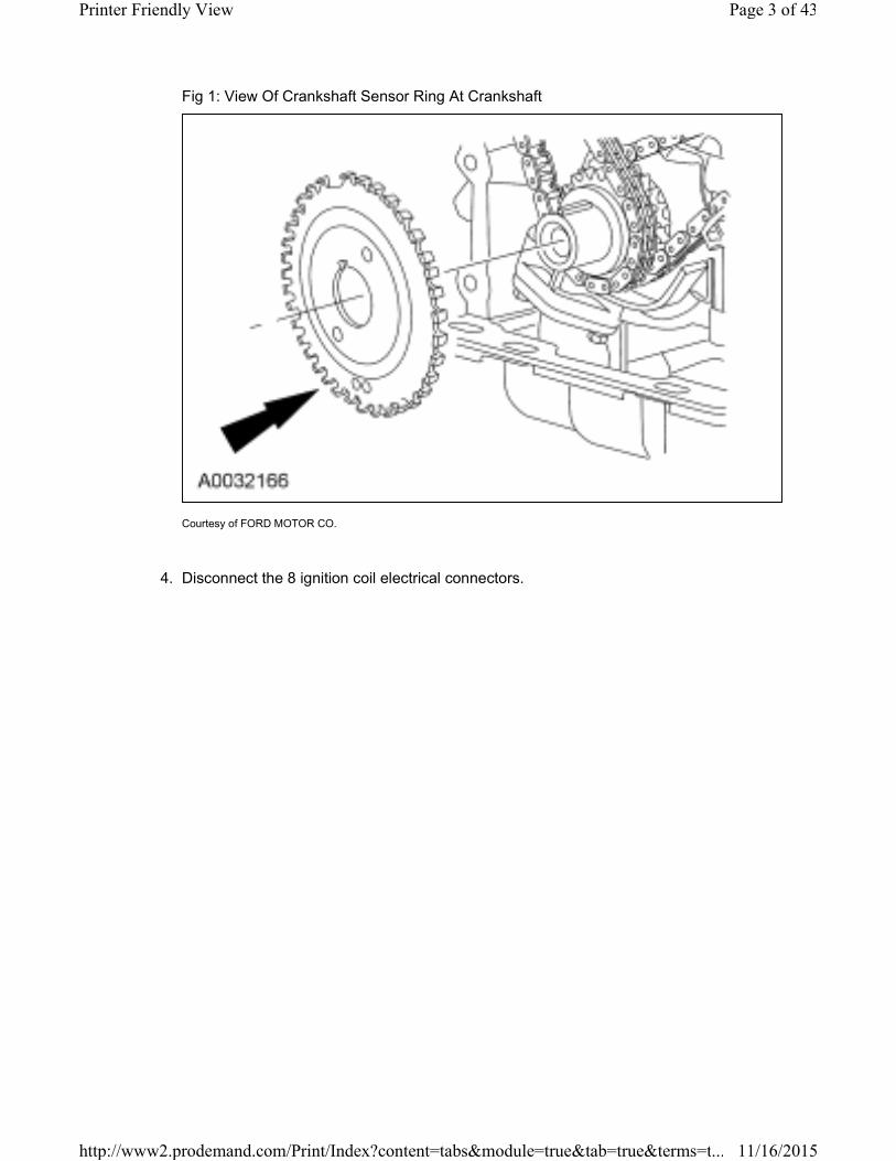
Fig 1: View Of Crankshaft Sensor Ring At Crankshaft
Courtesy of FORD MOTOR CO.
4. Disconnect the 8 ignition coil electrical connectors.
Page 3 of 43Printer Friendly View
11/16/2015http://www2.prodemand.com/Print/Index?content=tabs&module=true&tab=true&terms=t...
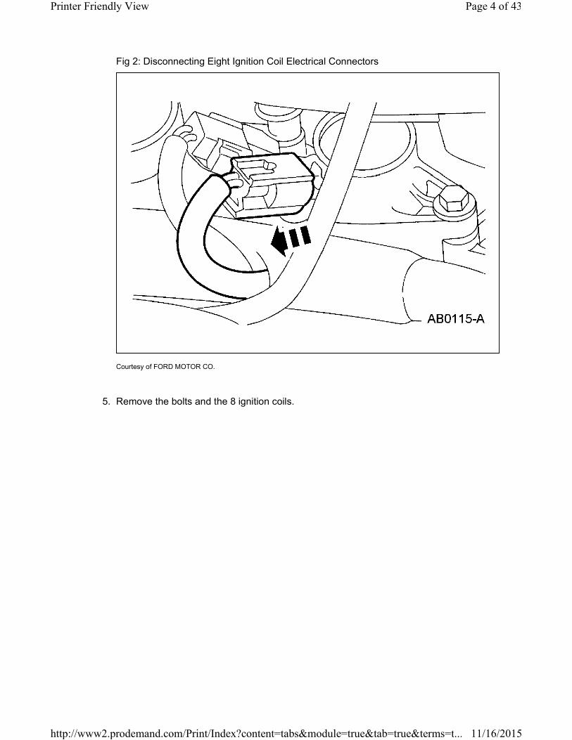
Fig 2: Disconnecting Eight Ignition Coil Electrical Connectors
Courtesy of FORD MOTOR CO.
5. Remove the bolts and the 8 ignition coils.
Page 4 of 43Printer Friendly View
11/16/2015http://www2.prodemand.com/Print/Index?content=tabs&module=true&tab=true&terms=t...

Fig 3: Removing Ignition Coils Bolts
Courtesy of FORD MOTOR CO.
NOTE: Use compressed air to remove any foreign material from the spark
plug wells before removing the spark plugs.
Page 5 of 43Printer Friendly View
11/16/2015http://www2.prodemand.com/Print/Index?content=tabs&module=true&tab=true&terms=t...
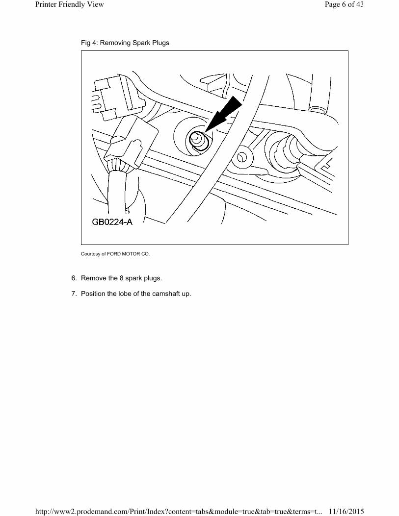
Fig 4: Removing Spark Plugs
Courtesy of FORD MOTOR CO.
6. Remove the 8 spark plugs.
7. Position the lobe of the camshaft up.
Page 6 of 43Printer Friendly View
11/16/2015http://www2.prodemand.com/Print/Index?content=tabs&module=true&tab=true&terms=t...
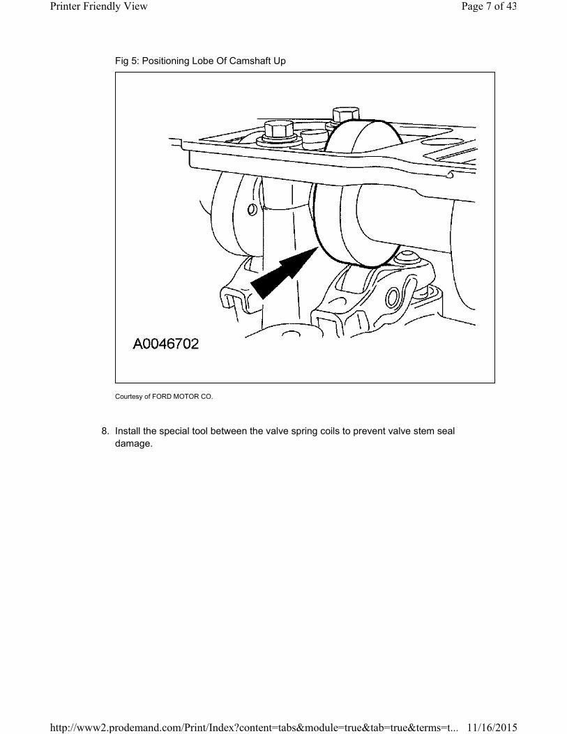
Fig 5: Positioning Lobe Of Camshaft Up
Courtesy of FORD MOTOR CO.
8. Install the special tool between the valve spring coils to prevent valve stem seal
damage.
Page 7 of 43Printer Friendly View
11/16/2015http://www2.prodemand.com/Print/Index?content=tabs&module=true&tab=true&terms=t...

Fig 6: Installing Special Tool Between Valve Spring Coils
Courtesy of FORD MOTOR CO.
NOTE: The roller followers are positional. Mark the followers for installation
in their original locations.
Page 8 of 43Printer Friendly View
11/16/2015http://www2.prodemand.com/Print/Index?content=tabs&module=true&tab=true&terms=t...
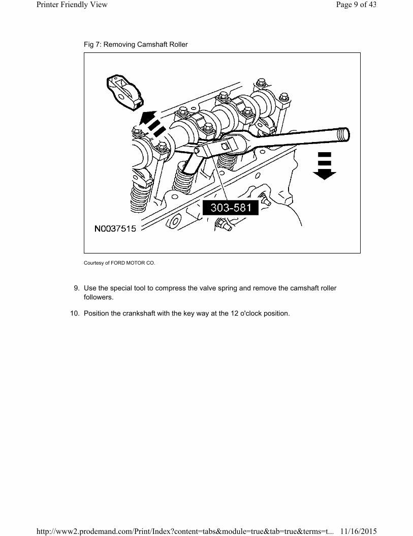
Fig 7: Removing Camshaft Roller
Courtesy of FORD MOTOR CO.
9. Use the special tool to compress the valve spring and remove the camshaft roller
followers.
10. Position the crankshaft with the key way at the 12 o'clock position.
Page 9 of 43Printer Friendly View
11/16/2015http://www2.prodemand.com/Print/Index?content=tabs&module=true&tab=true&terms=t...
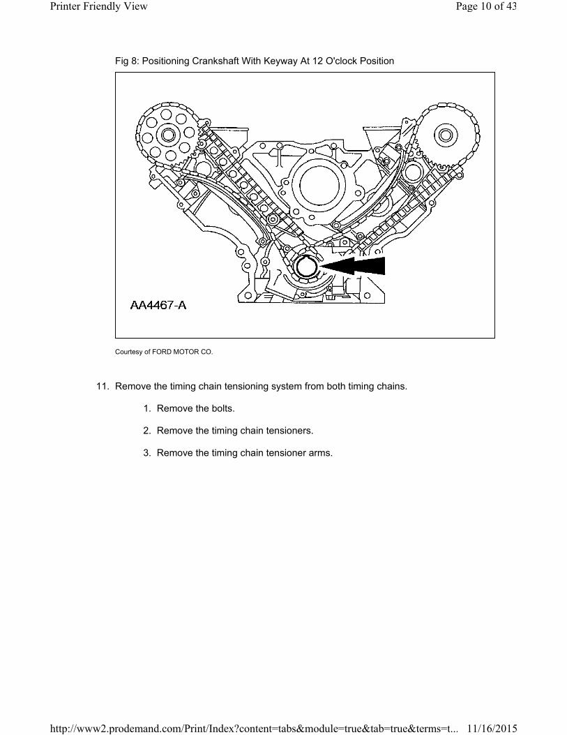
Fig 8: Positioning Crankshaft With Keyway At 12 O'clock Position
Courtesy of FORD MOTOR CO.
11. Remove the timing chain tensioning system from both timing chains.
1. Remove the bolts.
2. Remove the timing chain tensioners.
3. Remove the timing chain tensioner arms.
Page 10 of 43Printer Friendly View
11/16/2015http://www2.prodemand.com/Print/Index?content=tabs&module=true&tab=true&terms=t...

Fig 9: Identifying Timing Chain Tensioning System
Courtesy of FORD MOTOR CO.
12. Remove the LH and RH timing chains and the crankshaft sprocket.
1. Remove the RH timing chain from the camshaft sprocket.
2. Remove the RH timing chain from the crankshaft sprocket.
3. Repeat for the LH timing chain and crankshaft sprocket.
Page 11 of 43Printer Friendly View
11/16/2015http://www2.prodemand.com/Print/Index?content=tabs&module=true&tab=true&terms=t...
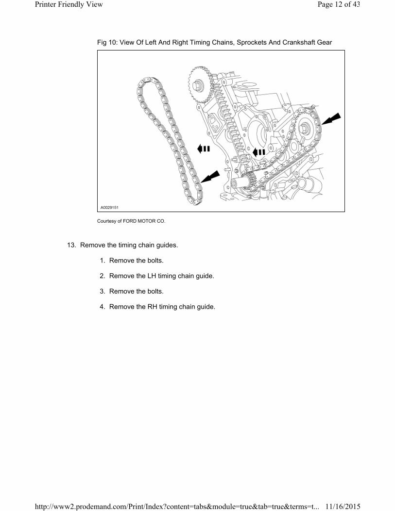
Fig 10: View Of Left And Right Timing Chains, Sprockets And Crankshaft Gear
Courtesy of FORD MOTOR CO.
13. Remove the timing chain guides.
1. Remove the bolts.
2. Remove the LH timing chain guide.
3. Remove the bolts.
4. Remove the RH timing chain guide.
Page 12 of 43Printer Friendly View
11/16/2015http://www2.prodemand.com/Print/Index?content=tabs&module=true&tab=true&terms=t...
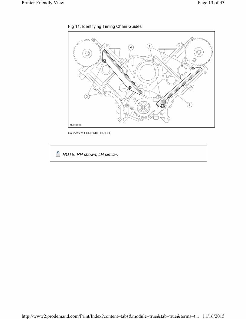
Fig 11: Identifying Timing Chain Guides
Courtesy of FORD MOTOR CO.
NOTE: RH shown, LH similar.
Page 13 of 43Printer Friendly View
11/16/2015http://www2.prodemand.com/Print/Index?content=tabs&module=true&tab=true&terms=t...
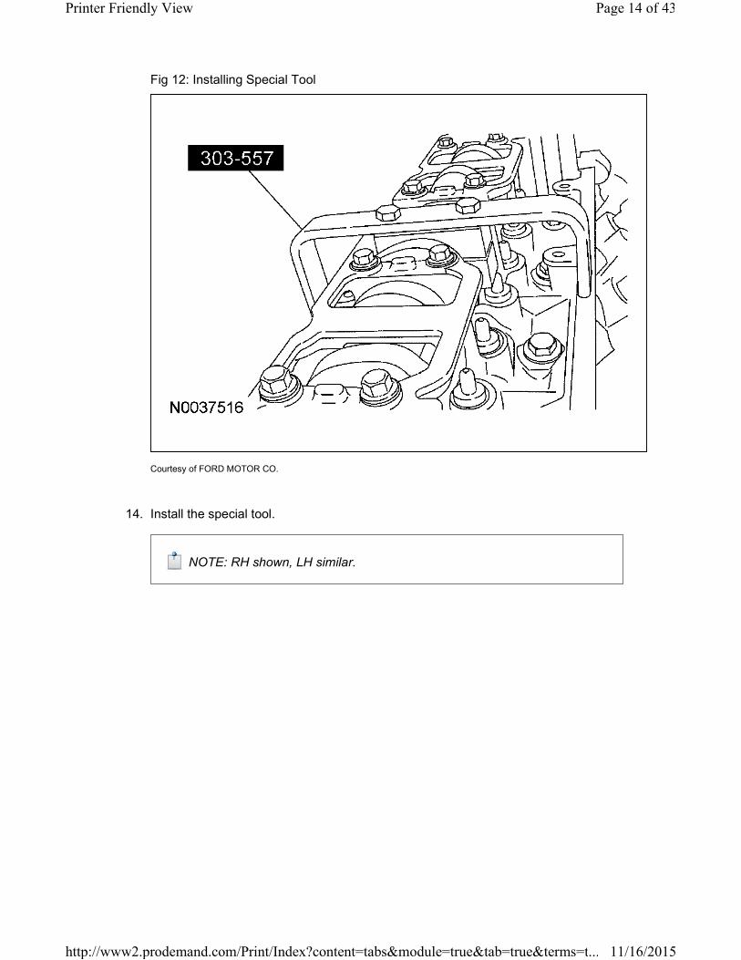
Fig 12: Installing Special Tool
Courtesy of FORD MOTOR CO.
14. Install the special tool.
NOTE: RH shown, LH similar.
Page 14 of 43Printer Friendly View
11/16/2015http://www2.prodemand.com/Print/Index?content=tabs&module=true&tab=true&terms=t...

Fig 13: Removing Camshaft Gear Bolt
Courtesy of FORD MOTOR CO.
15. Remove the bolt and the camshaft gear.
IN-VEHICLE REPAIR > TIMING DRIVE COMPONENTS > INSTALLATION
Engines with ratcheting timing chain tensioners
CAUTION: Timing chain procedure must be followed exactly or damage to
valves and pistons will result.
CAUTION: Do not compress the ratchet assembly. This will damage the
ratchet assembly.
NOTE: LH shown, RH similar.
Page 15 of 43Printer Friendly View
11/16/2015http://www2.prodemand.com/Print/Index?content=tabs&module=true&tab=true&terms=t...
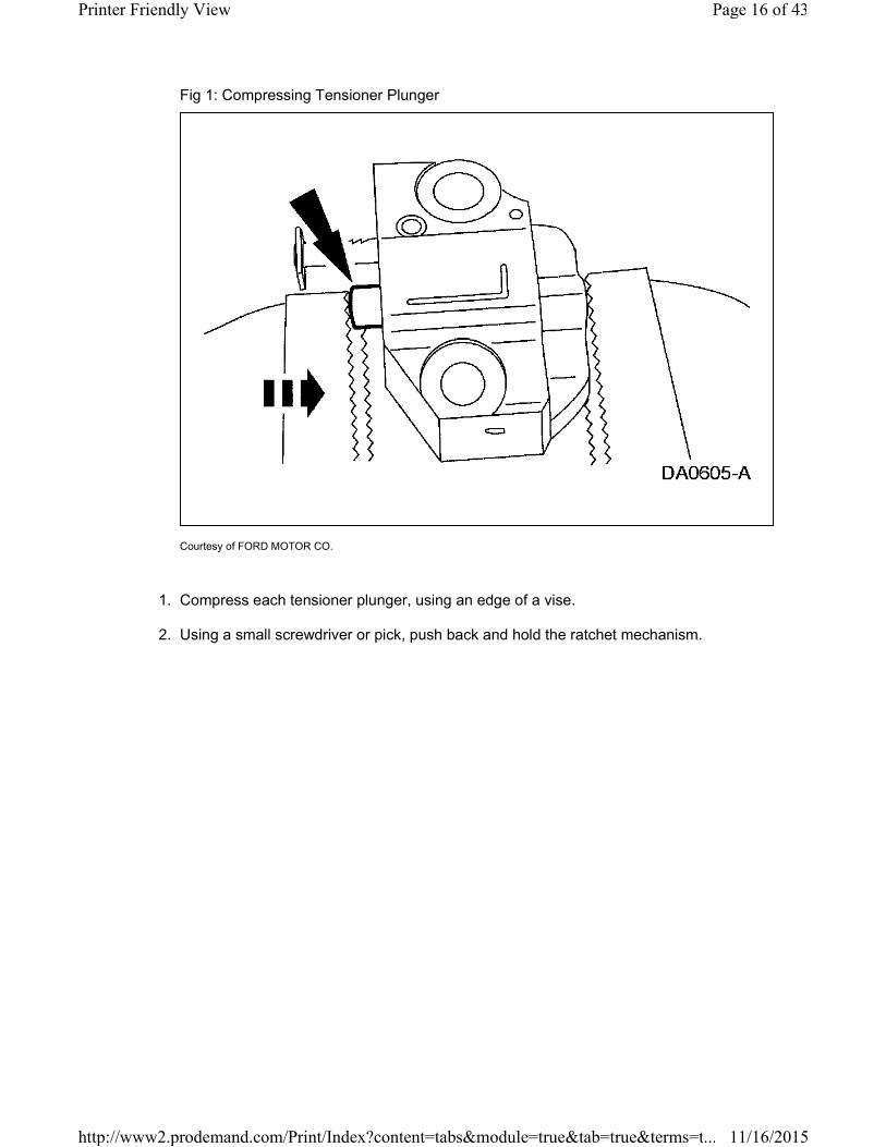
Fig 1: Compressing Tensioner Plunger
Courtesy of FORD MOTOR CO.
1. Compress each tensioner plunger, using an edge of a vise.
2. Using a small screwdriver or pick, push back and hold the ratchet mechanism.
Page 16 of 43Printer Friendly View
11/16/2015http://www2.prodemand.com/Print/Index?content=tabs&module=true&tab=true&terms=t...

Fig 2: Holding Ratchet Mechanism
Courtesy of FORD MOTOR CO.
3. While holding the ratchet mechanism, push the ratchet arm back into the tensioner
housing.
Page 17 of 43Printer Friendly View
11/16/2015http://www2.prodemand.com/Print/Index?content=tabs&module=true&tab=true&terms=t...
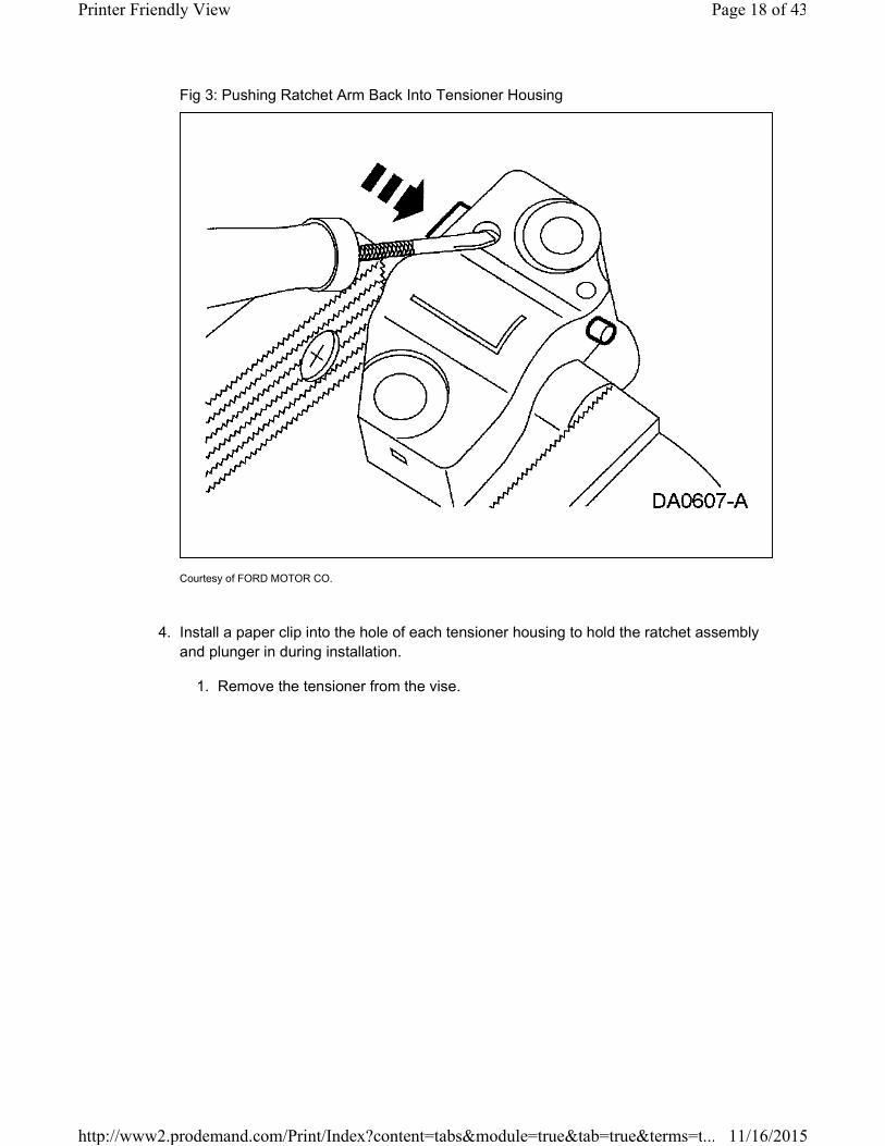
Fig 3: Pushing Ratchet Arm Back Into Tensioner Housing
Courtesy of FORD MOTOR CO.
4. Install a paper clip into the hole of each tensioner housing to hold the ratchet assembly
and plunger in during installation.
1. Remove the tensioner from the vise.
Page 18 of 43Printer Friendly View
11/16/2015http://www2.prodemand.com/Print/Index?content=tabs&module=true&tab=true&terms=t...

Fig 4: Installing Paper Clip Into Hole Of Tensioner Housing
Courtesy of FORD MOTOR CO.
Engines with non-ratcheting timing chain tensioners
CAUTION: If one or both tensioner mounting bolts are loosened or
removed, the tensioner-sealing bead must be inspected for seal integrity. Any
cracks, tears, cuts or separation from the tensioner body or permanent
compression of the seal bead, will require replacement of the tensioner.
5. Inspect the RH and LH timing chain tensioners.
1. Install new tensioners as necessary.
CAUTION: The timing chain procedure must be followed exactly or
damage to valves and pistons will result.
NOTE: LH shown, RH similar.
Page 19 of 43Printer Friendly View
11/16/2015http://www2.prodemand.com/Print/Index?content=tabs&module=true&tab=true&terms=t...
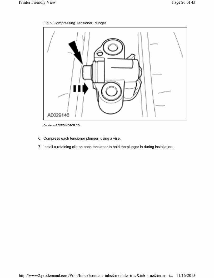
Fig 5: Compressing Tensioner Plunger
Courtesy of FORD MOTOR CO.
6. Compress each tensioner plunger, using a vise.
7. Install a retaining clip on each tensioner to hold the plunger in during installation.
Page 20 of 43Printer Friendly View
11/16/2015http://www2.prodemand.com/Print/Index?content=tabs&module=true&tab=true&terms=t...
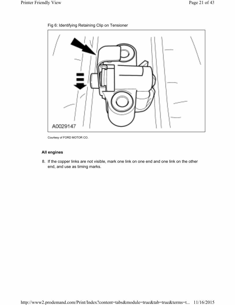
Fig 6: Identifying Retaining Clip on Tensioner
Courtesy of FORD MOTOR CO.
All engines
8. If the copper links are not visible, mark one link on one end and one link on the other
end, and use as timing marks.
Page 21 of 43Printer Friendly View
11/16/2015http://www2.prodemand.com/Print/Index?content=tabs&module=true&tab=true&terms=t...
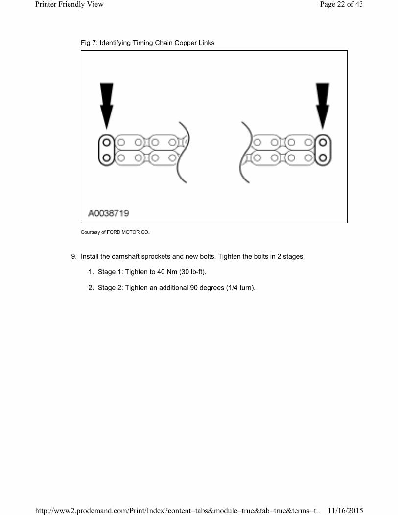
Fig 7: Identifying Timing Chain Copper Links
Courtesy of FORD MOTOR CO.
9. Install the camshaft sprockets and new bolts. Tighten the bolts in 2 stages.
1. Stage 1: Tighten to 40 Nm (30 lb-ft).
2. Stage 2: Tighten an additional 90 degrees (1/4 turn).
Page 22 of 43Printer Friendly View
11/16/2015http://www2.prodemand.com/Print/Index?content=tabs&module=true&tab=true&terms=t...
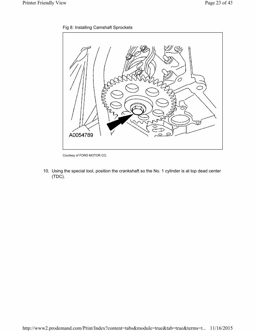
Fig 8: Installing Camshaft Sprockets
Courtesy of FORD MOTOR CO.
10. Using the special tool, position the crankshaft so the No. 1 cylinder is at top dead center
(TDC).
Page 23 of 43Printer Friendly View
11/16/2015http://www2.prodemand.com/Print/Index?content=tabs&module=true&tab=true&terms=t...
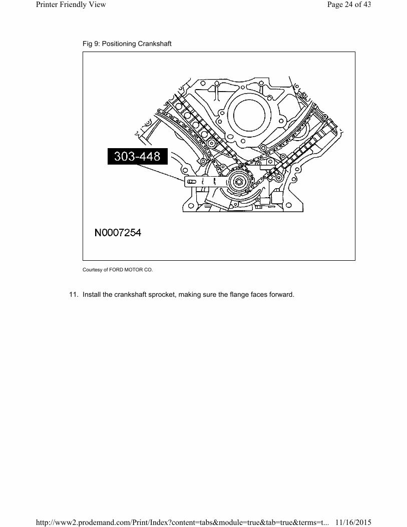
Fig 9: Positioning Crankshaft
Courtesy of FORD MOTOR CO.
11. Install the crankshaft sprocket, making sure the flange faces forward.
Page 24 of 43Printer Friendly View
11/16/2015http://www2.prodemand.com/Print/Index?content=tabs&module=true&tab=true&terms=t...
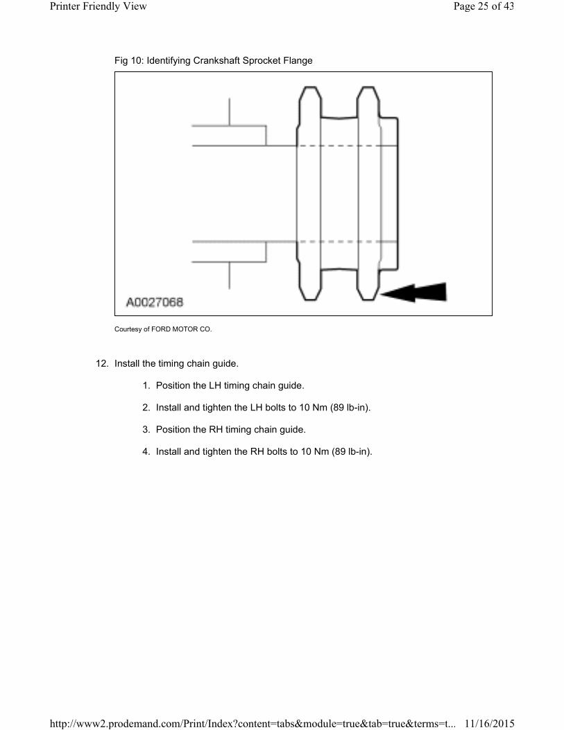
Fig 10: Identifying Crankshaft Sprocket Flange
Courtesy of FORD MOTOR CO.
12. Install the timing chain guide.
1. Position the LH timing chain guide.
2. Install and tighten the LH bolts to 10 Nm (89 lb-in).
3. Position the RH timing chain guide.
4. Install and tighten the RH bolts to 10 Nm (89 lb-in).
Page 25 of 43Printer Friendly View
11/16/2015http://www2.prodemand.com/Print/Index?content=tabs&module=true&tab=true&terms=t...
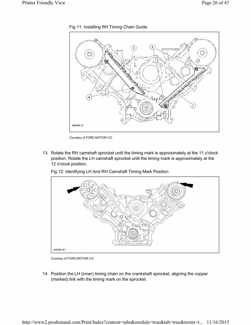
Fig 11: Installing RH Timing Chain Guide
Courtesy of FORD MOTOR CO.
13. Rotate the RH camshaft sprocket until the timing mark is approximately at the 11 o'clock
position. Rotate the LH camshaft sprocket until the timing mark is approximately at the
12 o'clock position.
Fig 12: Identifying LH And RH Camshaft Timing Mark Position
Courtesy of FORD MOTOR CO.
14. Position the LH (inner) timing chain on the crankshaft sprocket, aligning the copper
(marked) link with the timing mark on the sprocket.
Page 26 of 43Printer Friendly View
11/16/2015http://www2.prodemand.com/Print/Index?content=tabs&module=true&tab=true&terms=t...

Fig 13: Aligning Copper (Marked) Link With Timing Mark On Crankshaft Sprocket
Courtesy of FORD MOTOR CO.
15. Install the LH timing chain on the sprocket, aligning the copper (marked) link with the
timing marks on the sprocket.
Fig 14: Aligning Copper (Marked) Link With Timing Mark On Camshaft Sprocket
Courtesy of FORD MOTOR CO.
Page 27 of 43Printer Friendly View
11/16/2015http://www2.prodemand.com/Print/Index?content=tabs&module=true&tab=true&terms=t...
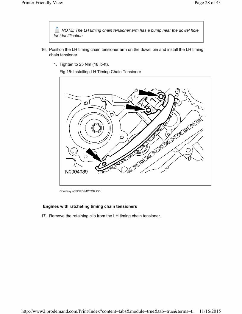
NOTE: The LH timing chain tensioner arm has a bump near the dowel hole
for identification.
16. Position the LH timing chain tensioner arm on the dowel pin and install the LH timing
chain tensioner.
1. Tighten to 25 Nm (18 lb-ft).
Fig 15: Installing LH Timing Chain Tensioner
Courtesy of FORD MOTOR CO.
Engines with ratcheting timing chain tensioners
17. Remove the retaining clip from the LH timing chain tensioner.
Page 28 of 43Printer Friendly View
11/16/2015http://www2.prodemand.com/Print/Index?content=tabs&module=true&tab=true&terms=t...
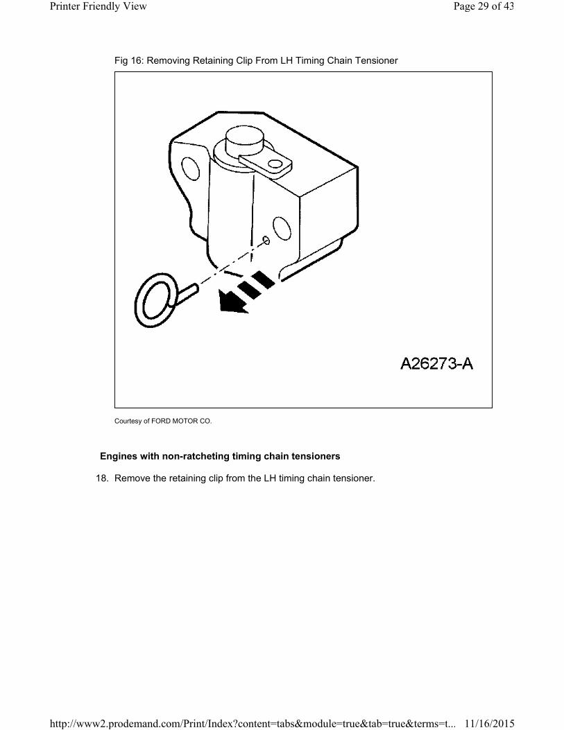
Fig 16: Removing Retaining Clip From LH Timing Chain Tensioner
Courtesy of FORD MOTOR CO.
Engines with non-ratcheting timing chain tensioners
18. Remove the retaining clip from the LH timing chain tensioner.
Page 29 of 43Printer Friendly View
11/16/2015http://www2.prodemand.com/Print/Index?content=tabs&module=true&tab=true&terms=t...
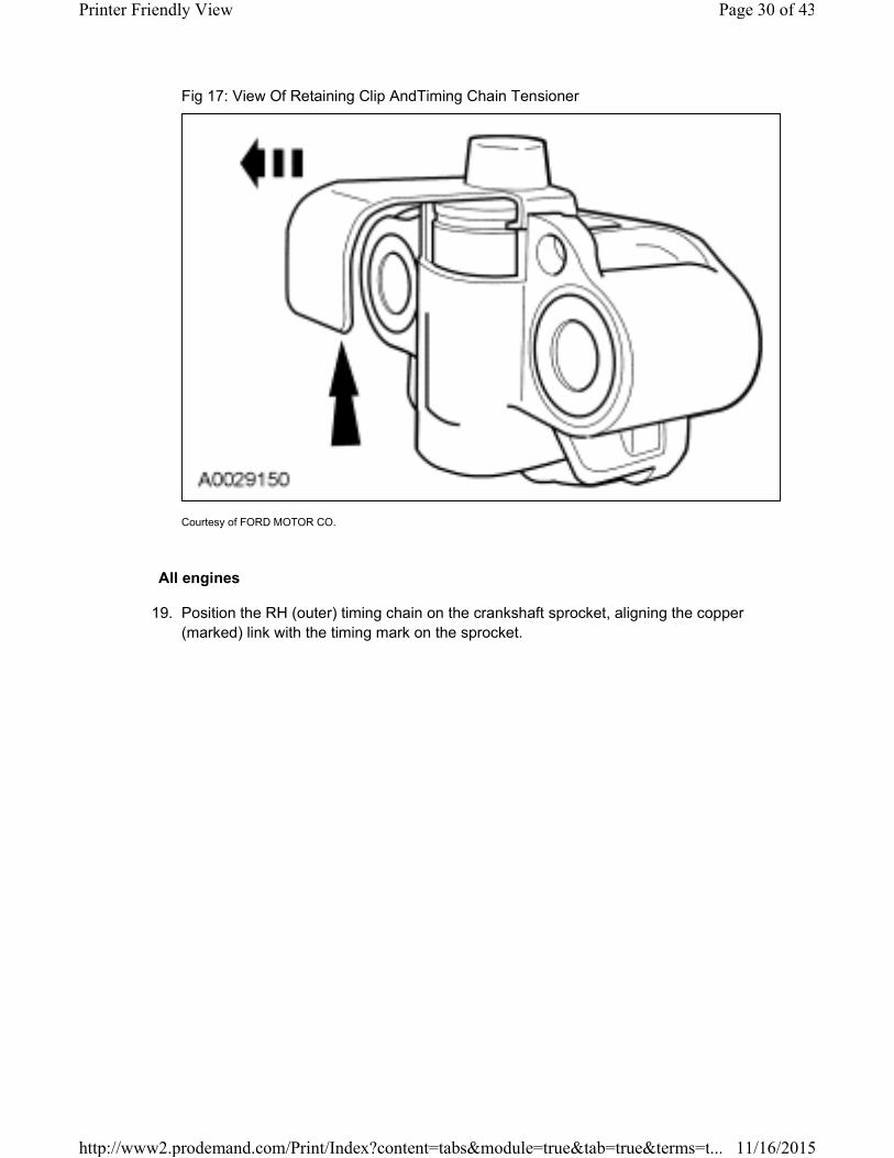
Fig 17: View Of Retaining Clip AndTiming Chain Tensioner
Courtesy of FORD MOTOR CO.
All engines
19. Position the RH (outer) timing chain on the crankshaft sprocket, aligning the copper
(marked) link with the timing mark on the sprocket.
Page 30 of 43Printer Friendly View
11/16/2015http://www2.prodemand.com/Print/Index?content=tabs&module=true&tab=true&terms=t...
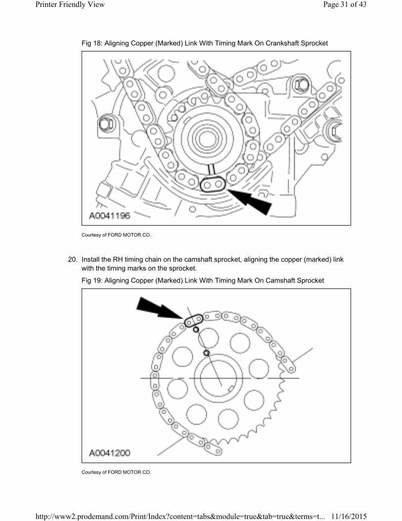
Fig 18: Aligning Copper (Marked) Link With Timing Mark On Crankshaft Sprocket
Courtesy of FORD MOTOR CO.
20. Install the RH timing chain on the camshaft sprocket, aligning the copper (marked) link
with the timing marks on the sprocket.
Fig 19: Aligning Copper (Marked) Link With Timing Mark On Camshaft Sprocket
Courtesy of FORD MOTOR CO.
Page 31 of 43Printer Friendly View
11/16/2015http://www2.prodemand.com/Print/Index?content=tabs&module=true&tab=true&terms=t...
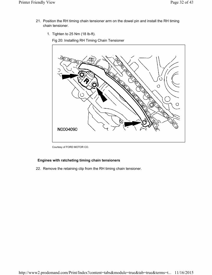
21. Position the RH timing chain tensioner arm on the dowel pin and install the RH timing
chain tensioner.
1. Tighten to 25 Nm (18 lb-ft).
Fig 20: Installing RH Timing Chain Tensioner
Courtesy of FORD MOTOR CO.
Engines with ratcheting timing chain tensioners
22. Remove the retaining clip from the RH timing chain tensioner.
Page 32 of 43Printer Friendly View
11/16/2015http://www2.prodemand.com/Print/Index?content=tabs&module=true&tab=true&terms=t...

Fig 21: Removing Retaining Clip From RH Timing Chain Tensioner
Courtesy of FORD MOTOR CO.
Engines with non-ratcheting timing chain tensioners
23. Remove the retaining clip from the RH timing chain tensioner.
Page 33 of 43Printer Friendly View
11/16/2015http://www2.prodemand.com/Print/Index?content=tabs&module=true&tab=true&terms=t...
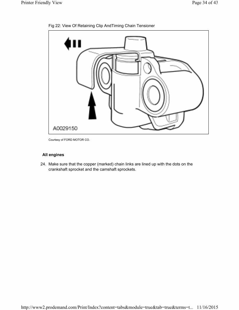
Fig 22: View Of Retaining Clip AndTiming Chain Tensioner
Courtesy of FORD MOTOR CO.
All engines
24. Make sure that the copper (marked) chain links are lined up with the dots on the
crankshaft sprocket and the camshaft sprockets.
Page 34 of 43Printer Friendly View
11/16/2015http://www2.prodemand.com/Print/Index?content=tabs&module=true&tab=true&terms=t...
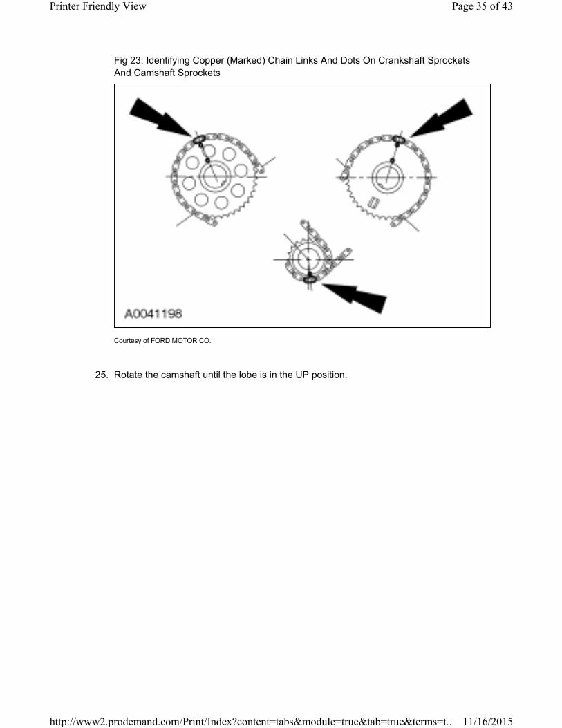
Fig 23: Identifying Copper (Marked) Chain Links And Dots On Crankshaft Sprockets
And Camshaft Sprockets
Courtesy of FORD MOTOR CO.
25. Rotate the camshaft until the lobe is in the UP position.
Page 35 of 43Printer Friendly View
11/16/2015http://www2.prodemand.com/Print/Index?content=tabs&module=true&tab=true&terms=t...
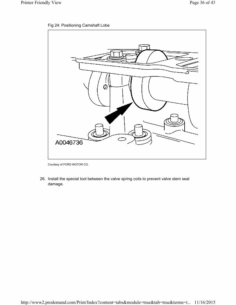
Fig 24: Positioning Camshaft Lobe
Courtesy of FORD MOTOR CO.
26. Install the special tool between the valve spring coils to prevent valve stem seal
damage.
Page 36 of 43Printer Friendly View
11/16/2015http://www2.prodemand.com/Print/Index?content=tabs&module=true&tab=true&terms=t...
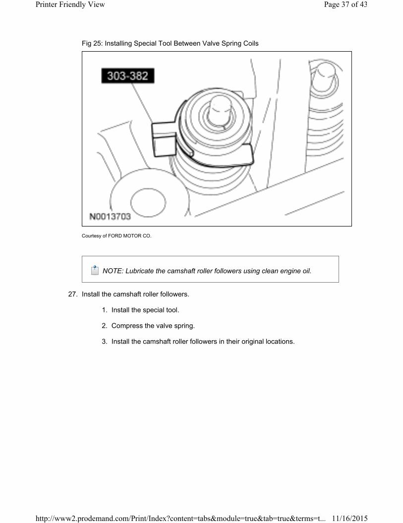
Fig 25: Installing Special Tool Between Valve Spring Coils
Courtesy of FORD MOTOR CO.
NOTE: Lubricate the camshaft roller followers using clean engine oil.
27. Install the camshaft roller followers.
1. Install the special tool.
2. Compress the valve spring.
3. Install the camshaft roller followers in their original locations.
Page 37 of 43Printer Friendly View
11/16/2015http://www2.prodemand.com/Print/Index?content=tabs&module=true&tab=true&terms=t...
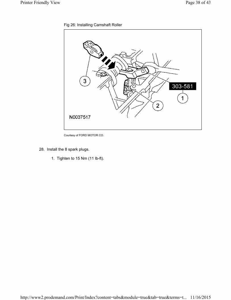
Fig 26: Installing Camshaft Roller
Courtesy of FORD MOTOR CO.
28. Install the 8 spark plugs.
1. Tighten to 15 Nm (11 lb-ft).
Page 38 of 43Printer Friendly View
11/16/2015http://www2.prodemand.com/Print/Index?content=tabs&module=true&tab=true&terms=t...
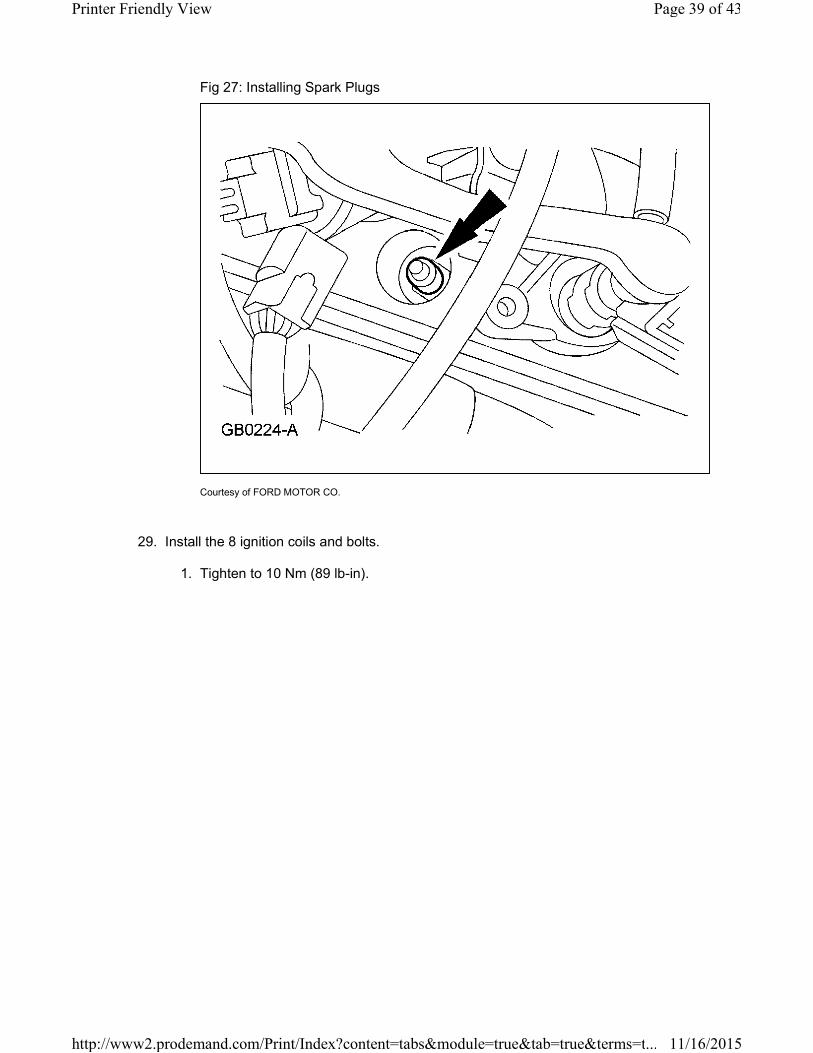
Fig 27: Installing Spark Plugs
Courtesy of FORD MOTOR CO.
29. Install the 8 ignition coils and bolts.
1. Tighten to 10 Nm (89 lb-in).
Page 39 of 43Printer Friendly View
11/16/2015http://www2.prodemand.com/Print/Index?content=tabs&module=true&tab=true&terms=t...
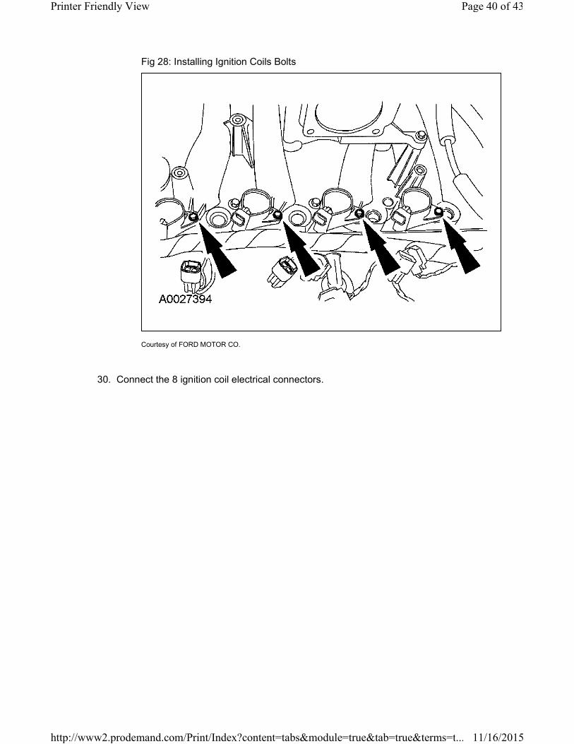
Fig 28: Installing Ignition Coils Bolts
Courtesy of FORD MOTOR CO.
30. Connect the 8 ignition coil electrical connectors.
Page 40 of 43Printer Friendly View
11/16/2015http://www2.prodemand.com/Print/Index?content=tabs&module=true&tab=true&terms=t...
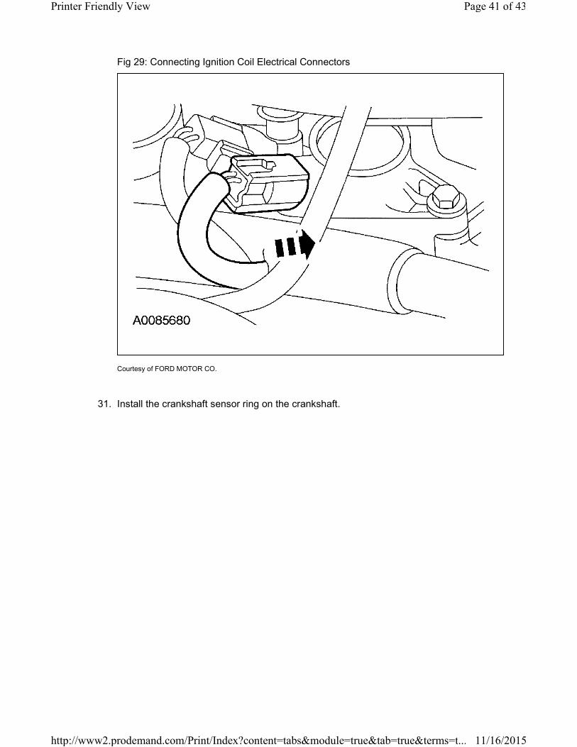
Fig 29: Connecting Ignition Coil Electrical Connectors
Courtesy of FORD MOTOR CO.
31. Install the crankshaft sensor ring on the crankshaft.
Page 41 of 43Printer Friendly View
11/16/2015http://www2.prodemand.com/Print/Index?content=tabs&module=true&tab=true&terms=t...
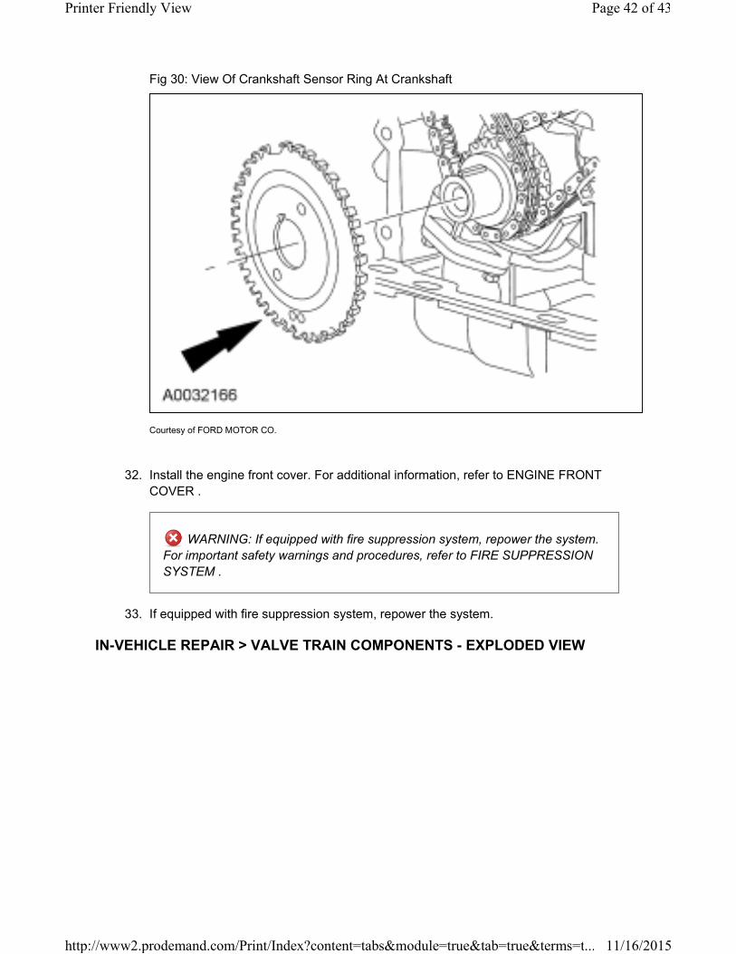
Fig 30: View Of Crankshaft Sensor Ring At Crankshaft
Courtesy of FORD MOTOR CO.
32. Install the engine front cover. For additional information, refer to ENGINE FRONT
COVER .
WARNING: If equipped with fire suppression system, repower the system.
For important safety warnings and procedures, refer to FIRE SUPPRESSION
SYSTEM .
33. If equipped with fire suppression system, repower the system.
IN-VEHICLE REPAIR > VALVE TRAIN COMPONENTS - EXPLODED VIEW
Page 42 of 43Printer Friendly View
11/16/2015http://www2.prodemand.com/Print/Index?content=tabs&module=true&tab=true&terms=t...
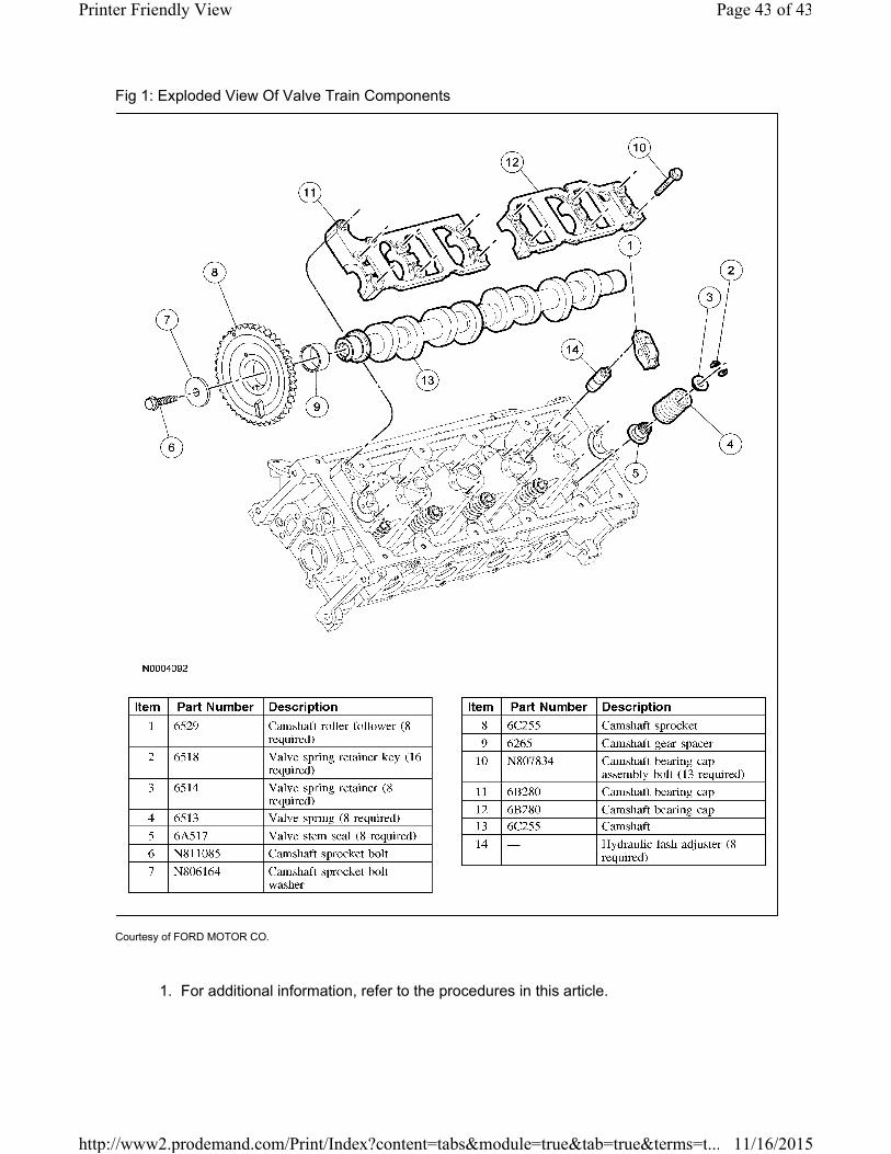
Fig 1: Exploded View Of Valve Train Components
Courtesy of FORD MOTOR CO.
1. For additional information, refer to the procedures in this article.
Page 43 of 43Printer Friendly View
11/16/2015http://www2.prodemand.com/Print/Index?content=tabs&module=true&tab=true&terms=t...


![TIMING CHAIN REMOVAL/INSTALLATION [L3 WITH TC]ww2.justanswer.com/uploads/SU/supermechanic/2013-04-28_114805... · 28/04/2013 · TIMING CHAIN REMOVAL/INSTALLATION [L3 WITH TC] ...](https://static.fdocuments.in/doc/165x107/5aab026c7f8b9a9c2e8b609f/timing-chain-removalinstallation-l3-with-tcww2-chain-removalinstallation-l3.jpg)