Service Manual - Daikin · Please read the warranty card for details. • When requesting no charge...
33
Service Manual Condensing Unit LRMEQ5-20AY1(E) Booster Unit LCBKQ3AV1(E) SiBE811111
Transcript of Service Manual - Daikin · Please read the warranty card for details. • When requesting no charge...
Service Manual
Condensing UnitLRMEQ5-20AY1(E)
Booster UnitLCBKQ3AV1(E)
SiBE811111
Table of Contents SiBE811111
1
Table of Contents1. Safety Precautions ..................................................................................22. Specifications (when the Condensing Unit is Connected to
Booster Units) .........................................................................................82.1 Condensing Unit - LRMEQ5-20AY1(E) ....................................................82.2 Booster Unit - LCBKQ3AV1(E).................................................................92.3 Operating Range of Booster Unit and Condensing Unit ........................10
3. Piping Connection Diagram ..................................................................114. Cooling Capacity Characteristics ..........................................................12
4.1 Booster Unit Capacity Characteristics....................................................124.2 Correction Method for Capacity Characteristics by Piping Length .........134.3 Condensing Unit Capacity Characteristics .............................................144.4 Precautions when Selecting a Thermal Expansion Valve ......................18
5. External Wiring Diagram .......................................................................196. Inspection & Refrigerant Charging Methods .........................................207. Test Operation Method .........................................................................218. Service Diagnosis .................................................................................23
8.1 Checking Error Codes (Condensing Unit) ..............................................238.2 Checking Error Codes (Booster Unit).....................................................248.3 Error Codes (Condensing Unit) ..............................................................258.4 Service Diagnosis...................................................................................258.5 Others, Diagnosis Details.......................................................................268.6 Diagnosis of Condensing Unit Droop Factors ........................................27
9. Reference Data .....................................................................................289.1 Protection Parts List (Condensing Unit) .................................................289.2 Protection Parts List (Booster Unit) ........................................................309.3 Sensor Characteristics ...........................................................................31
Subject models: LRMEQ5-20AY1(E)LCBKQ3AV1(E)
(∗Freezer models: Booster units cannot be connected to LRLEQ5-20AY1)
SiBE811111 Safety Precautions
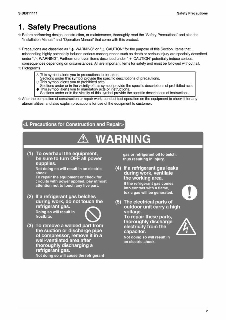
1. Safety PrecautionsBefore performing design, construction, or maintenance, thoroughly read the "Safety Precautions" and also the "Installation Manual" and "Operation Manual" that come with this product.
Precautions are classified as " WARNING" or " CAUTION" for the purpose of this Section. Items that mishandling highly potentially induces serious consequences such as death or serious injury are specially described under " WARNING". Furthermore, even items described under " CAUTION" potentially induce serious consequences depending on circumstances. All are important items for safety and must be followed without fail.Pictograms
After the completion of construction or repair work, conduct test operation on the equipment to check it for any abnormalities, and also explain precautions for use of the equipment to customer.
∆ This symbol alerts you to precautions to be taken.Sections under this symbol provide the specific descriptions of precautions.
k This symbol alerts you to prohibited acts.Sections under or in the vicinity of this symbol provide the specific descriptions of prohibited acts.
h This symbol alerts you to mandatory acts or instructions.Sections under or in the vicinity of this symbol provide the specific descriptions of instructions.
WARNING<I. Precautions for Construction and Repair>
Not doing so will result in an electric shock.To repair the equipment or check for circuits with power applied, pay utmost attention not to touch any live part.
(1) To overhaul the equipment, be sure to turn OFF all power supplies.
(2) If a refrigerant gas belches during work, do not touch the refrigerant gas.Doing so will result in frostbite.
(3) To remove a welded part from the suction or discharge pipe of compressor, remove it in a well-ventilated area after thoroughly discharging a refrigerant gas.Not doing so will cause the refrigerant
gas or refrigerant oil to belch, thus resulting in injury.
(4) If a refrigerant gas leaks during work, ventilate the working area.If the refrigerant gas comes into contact with a flame, toxic gas will be generated.
(5) The electrical parts of outdoor unit carry a high voltage.To repair these parts, thoroughly discharge electricity from the capacitor.Not doing so will result in an electric shock.
2
Safety Precautions SiBE811111
CAUTION
WARNING
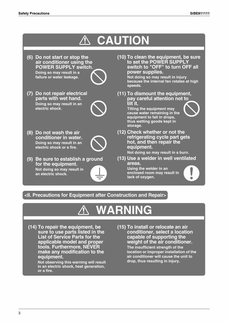
(6) Do not start or stop the air conditioner using the POWER SUPPLY switch.Doing so may result in a failure or water leakage.
(7) Do not repair electrical parts with wet hand.Doing so may result in an electric shock.
(8) Do not wash the air conditioner in water.Doing so may result in an electric shock or a fire.
(9) Be sure to establish a ground for the equipment.Not doing so may result in an electric shock.
(10) To clean the equipment, be sure to set the POWER SUPPLY switch to "OFF" to turn OFF all power supplies.Not doing so may result in injury because the internal fan rotates at high speeds.
(11) To dismount the equipment, pay careful attention not to tilt it.Tilting the equipment may cause water remaining in the equipment to fall in drops, thus wetting goods kept in storage.
(12) Check whether or not the refrigerating cycle part gets hot, and then repair the equipment.Not doing so may result in a burn.
(13) Use a welder in well ventilated areas.Using the welder in an enclosed room may result in lack of oxygen.
<II. Precautions for Equipment after Construction and Repair>
(14) To repair the equipment, be sure to use parts listed in the List of Service Parts for the applicable model and proper tools. Furthermore, NEVER make any modification to the equipment.Not observing this warning will result in an electric shock, heat generation, or a fire.
(15) To install or relocate an air conditioner, select a location capable of supporting the weight of the air conditioner.The insufficient strength of the location or improper installation of the air conditioner will cause the unit to drop, thus resulting in injury.
3
SiBE811111 Safety Precautions
WARNING
CAUTION
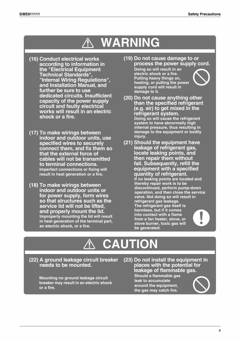
(16) Conduct electrical works according to information in the "Electrical Equipment Technical Standards", "Internal Wiring Regulations", and Installation Manual, and further be sure to use dedicated circuits. Insufficient capacity of the power supply circuit and faulty electrical works will result in an electric shock or a fire.
(17) To make wirings between indoor and outdoor units, use specified wires to securely connect them, and fix them so that the external force of cables will not be transmitted to terminal connections.Imperfect connections or fixing will result in heat generation or a fire.
(18) To make wirings between indoor and outdoor units or for power supply, form wires so that structures such as the service lid will not be lifted, and properly mount the lid.Improperly mounting the lid will result in heat generation of the terminal part, an electric shock, or a fire.
(19) Do not cause damage to or process the power supply cord.Doing so will result in an electric shock or a fire. Putting heavy things on, heating, or pulling the power supply cord will result in damage to it.
(20) Do not cause anything other than the specified refrigerant (e.g. air) to get mixed in the refrigerant system.Doing so will cause the refrigerant system to have abnormally high internal pressure, thus resulting in damage to the equipment or bodily injury.
(21) Should the equipment have leakage of refrigerant gas, locate leaking points, and then repair them without fail. Subsequently, refill the equipment with a specified quantity of refrigerant.
(22) A ground leakage circuit breaker needs to be mounted.
Mounting no ground leakage circuit breaker may result in an electric shock or a fire.
(23) Do not install the equipment in places with the potential for leakage of flammable gas.Should a flammable gas leak to accumulate around the equipment, the gas may catch fire.
If no leaking points are located and thereby repair work is to be discontinued, perform pump-down operation, and then close the service valve. Not doing so will result in refrigerant gas leakage. The refrigerant gas itself is harmless, but if it comes into contact with a flame from a fan heater, stove, or stove burner, toxic gas will be generated.
4
Safety Precautions SiBE811111
WARNING
CAUTION
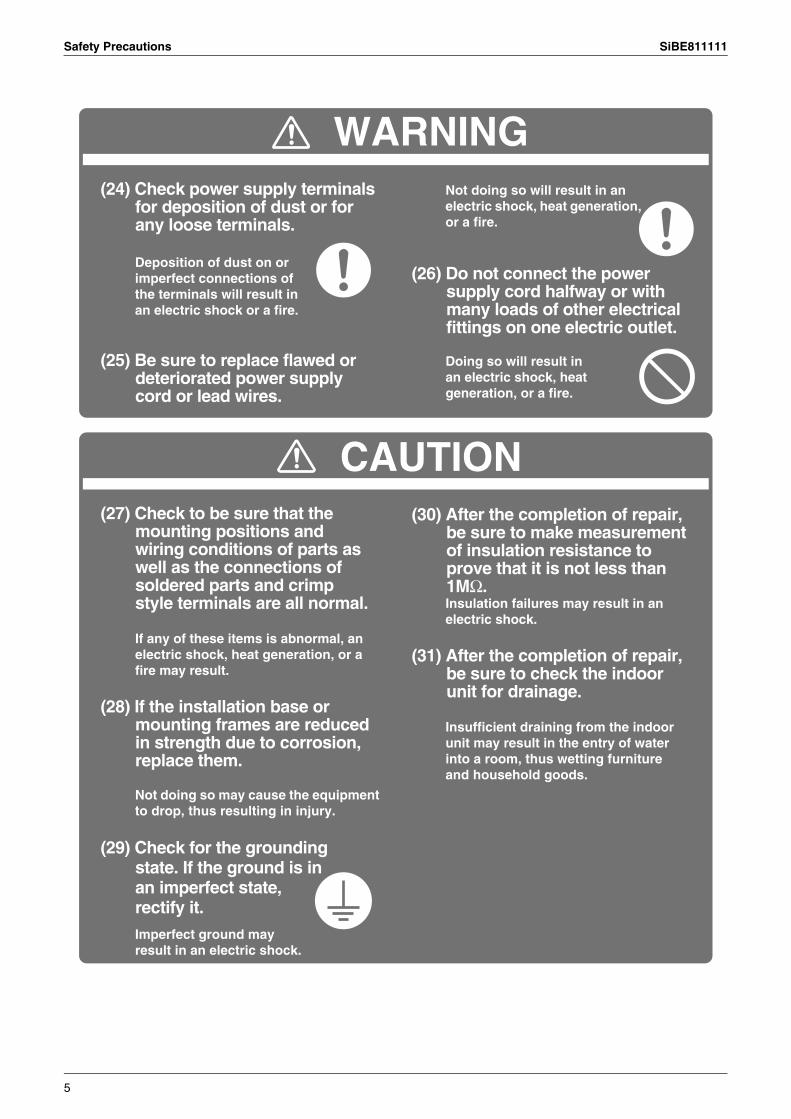
(24) Check power supply terminals for deposition of dust or for any loose terminals.
Deposition of dust on or imperfect connections of the terminals will result in an electric shock or a fire.
(25) Be sure to replace flawed or deteriorated power supply cord or lead wires.
Doing so will result in an electric shock, heat generation, or a fire.
(26) Do not connect the power supply cord halfway or with many loads of other electrical fittings on one electric outlet.
Not doing so will result in an electric shock, heat generation, or a fire.
(27) Check to be sure that the mounting positions and wiring conditions of parts as well as the connections of soldered parts and crimp style terminals are all normal.
If any of these items is abnormal, an electric shock, heat generation, or a fire may result.
(28) If the installation base or mounting frames are reduced in strength due to corrosion, replace them.
(29) Check for the grounding state. If the ground is in an imperfect state, rectify it.
Not doing so may cause the equipment to drop, thus resulting in injury.
Imperfect ground may result in an electric shock.
(31) After the completion of repair, be sure to check the indoor unit for drainage.
Insulation failures may result in an electric shock.
Insufficient draining from the indoor unit may result in the entry of water into a room, thus wetting furniture and household goods.
(30) After the completion of repair, be sure to make measurement of insulation resistance to prove that it is not less than 1MΩ.
5
SiBE811111 Safety Precautions
About the Product Warranty
Secondary disasters caused by a product abnormality such as those to refrigerated products and sales assurances are not subject to the warranty. When there is a risk of secondary disasters, regularly perform temperature management and install a warning system or reserve equipment after consulting with the dealer where the product was purchased. Also acquire damage insurance in advance.
• A warranty card is included with this product.The necessary information on the warranty card is completed by the dealer where the product was purchased and handed over. After verifying the information written on the warranty card, the persons who manage the refrigerator should store it carefully in a safe place.
Warranty period: 1 year from installation datePlease read the warranty card for details.• When requesting no charge repairs during the warranty period, first contact the dealer or the Daikin contact center
and always present the warranty card when the product is repaired.If the warranty card is not presented, a service fee may be charged even during the no charge warranty period, so store the warranty card carefully in a safe place.
However, for the warranty corresponding to the content listed below, the product will be repaired for a service fee even during the no charge warranty period.
• Accidents in usage outside the usage specificationsRefer to the usage specifications for each model series.
• For the below problems in selection, installation, construction, or other problems, "Ex." indicates concrete examples.
1. Model selection problems• When making a selection inappropriate for the storage application
Ex: Cooling goods that are not the storage temperature• When selecting a load that is too large or too small for the cooling capacity• For problems from the selection error of electronic expansion valve or solenoid valve at refrigeration side.
Ex: Defective cooling because the electronic expansion valve capacity is too small
2. Installation problems (installation and installation environment)• When not installed in a level and stable location
Ex: Unit is not secured• When the installed atmosphere differs from normal atmospheric conditions
Ex: Salt spray atmosphere, oil mist atmosphere, near kitchen exhaustOther corrosive gas/adhesive mist atmospheres
• For exhaust heat problems, exhaust heat remaining from poor ventilationEx: Exhaust air is sucked back into the equipment
• When there is no solenoid valve at refrigeration side• When there is an installation defect in the electronic expansion valve at refrigeration side
Ex: Feeler bulb is disconnected from the piping• When the refrigerant piping size is not specified• When drainage water cannot be smoothly discharged from the refrigeration unit
Ex: The drainage water pipe slope does not reach 6° or higherEx: Not insulated or the heater is not installed (for the freezer stage)
• When the drain pipe has no trap installed or is inappropriate in the refrigeration unitEx: Water column not 200 mm or higher
• When vacuum drying in the refrigerant piping system is insufficientEx: Clogging from fine moisture crystals
• When the air tightness in the refrigerant piping system is insufficientEx: Refrigerant gas leakage
• When foreign objects contaminate the inside of the refrigerant piping systemEx: Clogging in fine sections of the system
1 Secondary warranty
2 No charge warranty period & subject
3 Situations that do not correspond to the no charge warranty (outside warranty scope)
6
Safety Precautions SiBE811111
• When field improvement construction has a negative effectEx: When used outside the usage temperature range because of field improvements
• When an accident occurs because of mishandling during installationEx: Outer panel looseness/vibration and pipes breaking/bending
• When the product is alteredEx: The pressure switch is short circuited
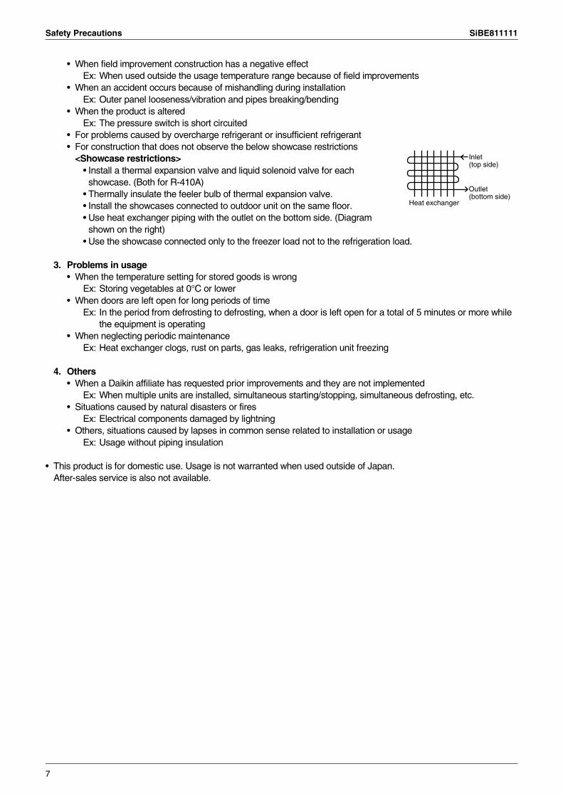
• For problems caused by overcharge refrigerant or insufficient refrigerant• For construction that does not observe the below showcase restrictions
<Showcase restrictions>• Install a thermal expansion valve and liquid solenoid valve for each
showcase. (Both for R-410A)• Thermally insulate the feeler bulb of thermal expansion valve.• Install the showcases connected to outdoor unit on the same floor.• Use heat exchanger piping with the outlet on the bottom side. (Diagram
shown on the right)• Use the showcase connected only to the freezer load not to the refrigeration load.
3. Problems in usage• When the temperature setting for stored goods is wrong
Ex: Storing vegetables at 0°C or lower• When doors are left open for long periods of time
Ex: In the period from defrosting to defrosting, when a door is left open for a total of 5 minutes or more while the equipment is operating
• When neglecting periodic maintenanceEx: Heat exchanger clogs, rust on parts, gas leaks, refrigeration unit freezing
4. Others• When a Daikin affiliate has requested prior improvements and they are not implemented
Ex: When multiple units are installed, simultaneous starting/stopping, simultaneous defrosting, etc.• Situations caused by natural disasters or fires
Ex: Electrical components damaged by lightning• Others, situations caused by lapses in common sense related to installation or usage
Ex: Usage without piping insulation
• This product is for domestic use. Usage is not warranted when used outside of Japan.After-sales service is also not available.
Heat exchanger
Inlet(top side)
Outlet(bottom side)
7
SiBE811111 Specifications (when the Condensing Unit is Connected to Booster Units)
2. Specifications (when the Condensing Unit is Connected to Booster Units)
For PCB micro-computer software versions below, a software update is required.• When a software update is required.
Condensing unit: ver. 52 (EB09058(D))Booster unit: ver. 34 (EC08008(B) or EC08009(B))
• When a software update is not required.Condensing unit: ver. 80 or higher (EB09060(D or after) or EB09061(D or after))Booster unit: ver. 38 or higher (EC09096(C or after) or EC09097(C or after))
After updating the software, always note the micro-computer software version on PCB.Condensing unit: ver. 80, Booster unit: ver. 38
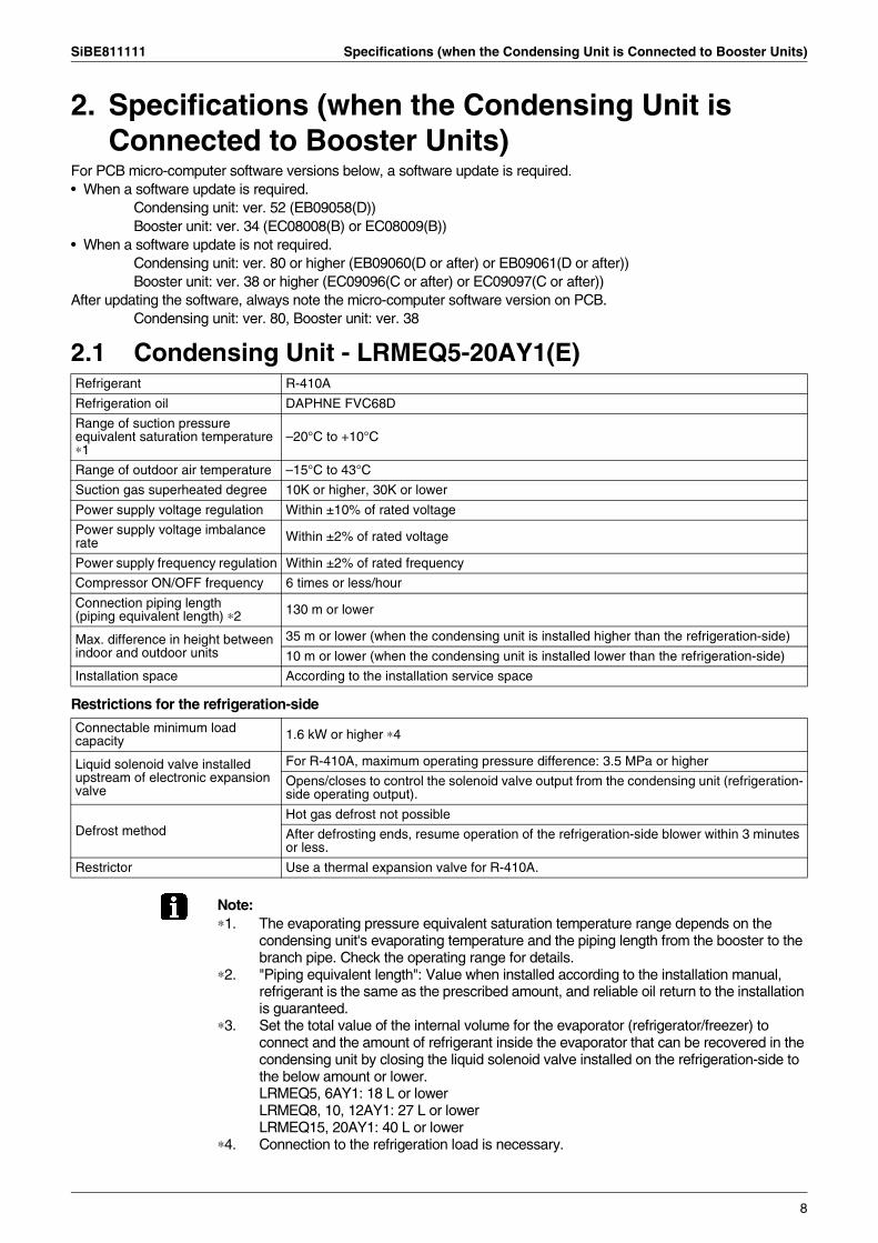
2.1 Condensing Unit - LRMEQ5-20AY1(E)
Restrictions for the refrigeration-side
Note:∗1. The evaporating pressure equivalent saturation temperature range depends on the
condensing unit's evaporating temperature and the piping length from the booster to the branch pipe. Check the operating range for details.
∗2. "Piping equivalent length": Value when installed according to the installation manual, refrigerant is the same as the prescribed amount, and reliable oil return to the installation is guaranteed.
∗3. Set the total value of the internal volume for the evaporator (refrigerator/freezer) to connect and the amount of refrigerant inside the evaporator that can be recovered in the condensing unit by closing the liquid solenoid valve installed on the refrigeration-side to the below amount or lower.LRMEQ5, 6AY1: 18 L or lowerLRMEQ8, 10, 12AY1: 27 L or lowerLRMEQ15, 20AY1: 40 L or lower
∗4. Connection to the refrigeration load is necessary.
Refrigerant R-410A
Refrigeration oil DAPHNE FVC68D
Range of suction pressure equivalent saturation temperature ∗1
–20°C to +10°C
Range of outdoor air temperature –15°C to 43°C
Suction gas superheated degree 10K or higher, 30K or lower
Power supply voltage regulation Within ±10% of rated voltage
Power supply voltage imbalance rate Within ±2% of rated voltage
Power supply frequency regulation Within ±2% of rated frequency
Compressor ON/OFF frequency 6 times or less/hour
Connection piping length(piping equivalent length) ∗2 130 m or lower
Max. difference in height between indoor and outdoor units
35 m or lower (when the condensing unit is installed higher than the refrigeration-side)
10 m or lower (when the condensing unit is installed lower than the refrigeration-side)
Installation space According to the installation service space
Connectable minimum load capacity 1.6 kW or higher ∗4
Liquid solenoid valve installed upstream of electronic expansion valve
For R-410A, maximum operating pressure difference: 3.5 MPa or higher
Opens/closes to control the solenoid valve output from the condensing unit (refrigeration-side operating output).
Defrost methodHot gas defrost not possible
After defrosting ends, resume operation of the refrigeration-side blower within 3 minutes or less.
Restrictor Use a thermal expansion valve for R-410A.
8
Specifications (when the Condensing Unit is Connected to Booster Units) SiBE811111
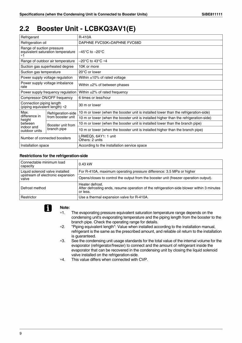
2.2 Booster Unit - LCBKQ3AV1(E)
Restrictions for the refrigeration-side
Note:∗1. The evaporating pressure equivalent saturation temperature range depends on the
condensing unit's evaporating temperature and the piping length from the booster to the branch pipe. Check the operating range for details.
∗2. "Piping equivalent length": Value when installed according to the installation manual, refrigerant is the same as the prescribed amount, and reliable oil return to the installation is guaranteed.
∗3. See the condensing unit usage standards for the total value of the internal volume for the evaporator (refrigerator/freezer) to connect and the amount of refrigerant inside the evaporator that can be recovered in the condensing unit by closing the liquid solenoid valve installed on the refrigeration-side.
∗4. This value differs when connected with CVP.
Refrigerant R-410A
Refrigeration oil DAPHNE FVC50K+DAPHNE FVC68D
Range of suction pressure equivalent saturation temperature ∗1
–45°C to –20°C
Range of outdoor air temperature –20°C to 43°C ∗4
Suction gas superheated degree 10K or more
Suction gas temperature 20°C or lower
Power supply voltage regulation Within ±10% of rated voltage
Power supply voltage imbalance rate Within ±2% of between phases
Power supply frequency regulation Within ±2% of rated frequency
Compressor ON/OFF frequency 6 times or less/hour
Connection piping length(piping equivalent length) ∗2 30 m or lower
Max. difference in height between indoor and outdoor units
Refrigeration-side from booster unit
10 m or lower (when the booster unit is installed lower than the refrigeration-side)
10 m or lower (when the booster unit is installed higher than the refrigeration-side)
Booster unit from branch pipe
10 m or lower (when the booster unit is installed lower than the branch pipe)
10 m or lower (when the booster unit is installed higher than the branch pipe)
Number of connected boosters LRMEQ5, 6AY1: 1 unitOthers: 2 units
Installation space According to the installation service space
Connectable minimum load capacity 0.43 kW
Liquid solenoid valve installed upstream of electronic expansion valve
For R-410A, maximum operating pressure difference: 3.5 MPa or higher
Opens/closes to control the output from the booster unit (freezer operation output).
Defrost methodHeater defrost.After defrosting ends, resume operation of the refrigeration-side blower within 3 minutes or less.
Restrictor Use a thermal expansion valve for R-410A.
9
SiBE811111 Specifications (when the Condensing Unit is Connected to Booster Units)
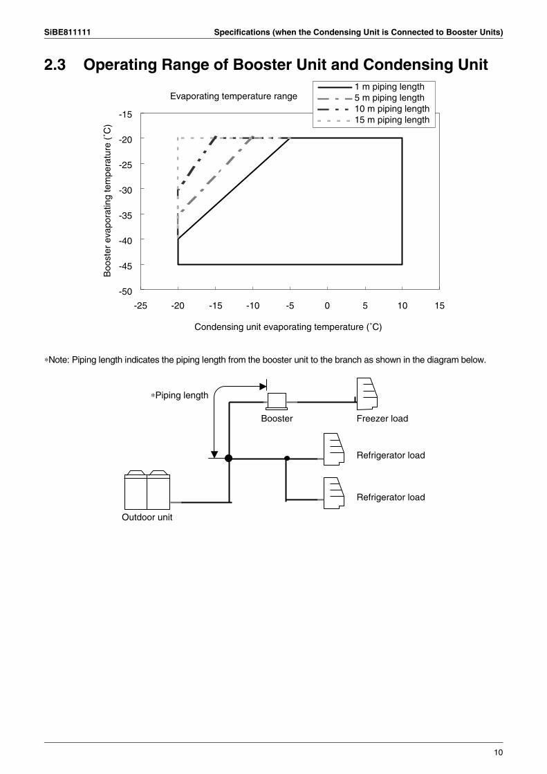
2.3 Operating Range of Booster Unit and Condensing Unit
∗Note: Piping length indicates the piping length from the booster unit to the branch as shown in the diagram below.
Evaporating temperature range
-25 -20 -15 -10 -5 0 5 10 15
Boo
ster
eva
pora
ting
tem
pera
ture
(˚C
)-15
-20
-25
-30
-35
-40
-45
-50
1 m piping length5 m piping length10 m piping length15 m piping length
Condensing unit evaporating temperature (˚C)
Booster Freezer load
Refrigerator load
Refrigerator load
Outdoor unit
∗Piping length
10
Piping Connection Diagram SiBE811111
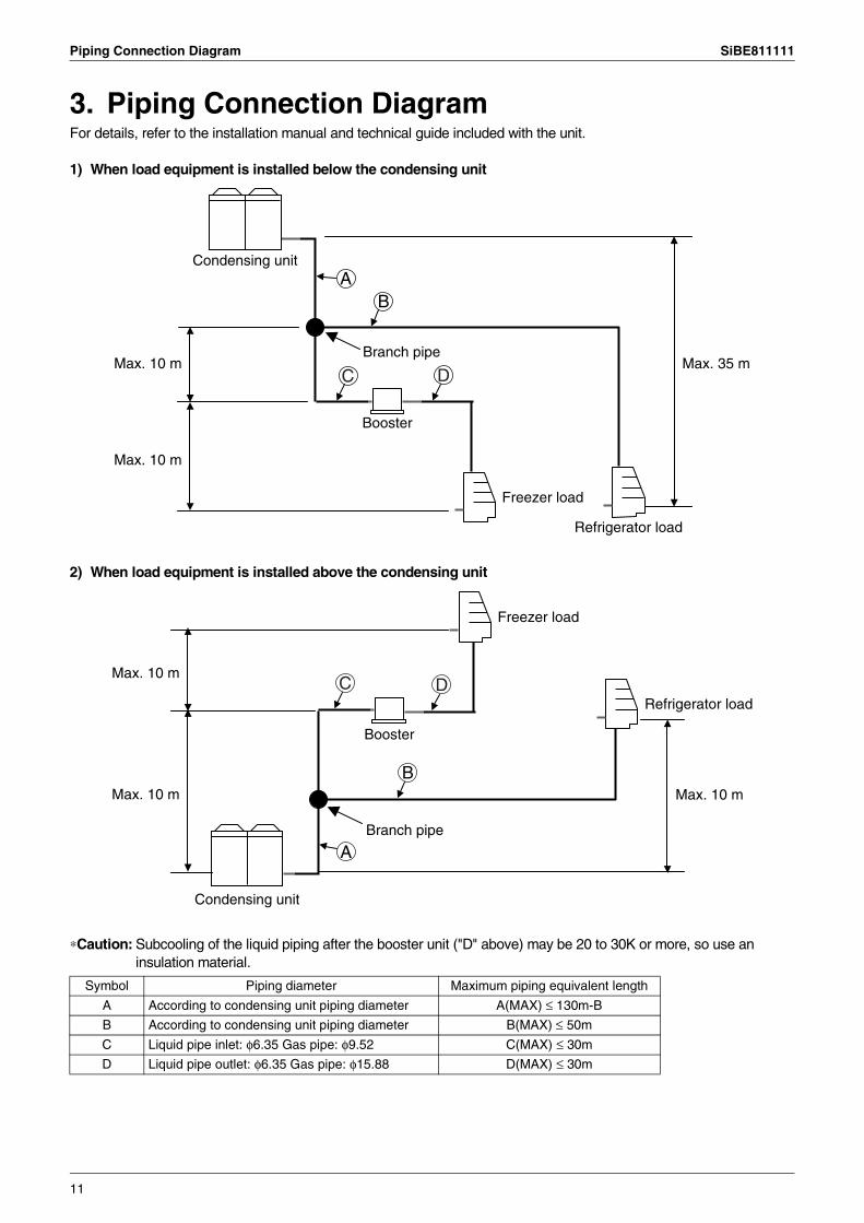
3. Piping Connection DiagramFor details, refer to the installation manual and technical guide included with the unit.
1) When load equipment is installed below the condensing unit
2) When load equipment is installed above the condensing unit
∗Caution: Subcooling of the liquid piping after the booster unit ("D" above) may be 20 to 30K or more, so use an insulation material.
Symbol Piping diameter Maximum piping equivalent length
A According to condensing unit piping diameter A(MAX) ≤ 130m-B
B According to condensing unit piping diameter B(MAX) ≤ 50m
C Liquid pipe inlet: φ6.35 Gas pipe: φ9.52 C(MAX) ≤ 30m
D Liquid pipe outlet: φ6.35 Gas pipe: φ15.88 D(MAX) ≤ 30m
Condensing unit
B
Max. 35 m
Max. 10 m
Max. 10 mBranch pipe
Booster
Freezer load
Refrigerator load
C D
A
A
BMax. 10 m
Max. 10 m
Max. 10 m
Freezer load
Booster
Branch pipe
Refrigerator load
Condensing unit
C D
11
SiBE811111 Cooling Capacity Characteristics
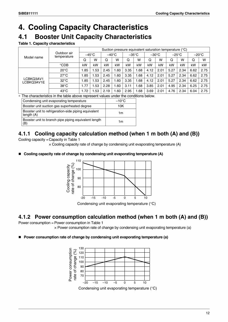
4. Cooling Capacity Characteristics4.1 Booster Unit Capacity CharacteristicsTable 1. Capacity characteristics
∗ The characteristics in the table above represent values under the conditions below.
4.1.1 Cooling capacity calculation method (when 1 m both (A) and (B))Cooling capacity =Capacity in Table 1
× Cooling capacity rate of change by condensing unit evaporating temperature (A)
Cooling capacity rate of change by condensing unit evaporating temperature (A)
4.1.2 Power consumption calculation method (when 1 m both (A) and (B))Power consumption = Power consumption in Table 1
× Power consumption rate of change by condensing unit evaporating temperature (a)
Power consumption rate of change by condensing unit evaporating temperature (a)
Model nameOutdoor air temperature
Suction pressure equivalent saturation temperature (°C)
–45°C –40°C –35°C –30°C –25°C –20°C
Q W Q W Q W Q W Q W Q W
°CDB kW kW kW kW kW kW kW kW kW kW kW kW
LCBKQ3AV1LCBKQ3AV1E
20°C 1.85 1.53 2.45 1.60 3.35 1.68 4.12 2.01 5.27 2.34 6.62 2.75
27°C 1.85 1.53 2.45 1.60 3.35 1.68 4.12 2.01 5.27 2.34 6.62 2.75
32°C 1.85 1.53 2.45 1.60 3.35 1.68 4.12 2.01 5.27 2.34 6.62 2.75
38°C 1.77 1.53 2.28 1.60 3.11 1.68 3.85 2.01 4.95 2.34 6.25 2.75
43°C 1.72 1.53 2.19 1.60 2.95 1.68 3.69 2.01 4.76 2.34 6.04 2.75
Condensing unit evaporating temperature –10°C
Booster unit suction gas superheated degree 10K
Booster unit to refrigeration-side piping equivalent length (A) 1m
Booster unit to branch pipe piping equivalent length (B) 1m
110
100
90
80
-20 -15 -10 10-5 50
Condensing unit evaporating temperature (°C)
Coo
ling
capa
city
ra
te o
f cha
nge
(%)
–20 –15 –10 10–5 50
130
120
110
100
90
8070
Pow
er c
onsu
mpt
ion
rate
of c
hang
e (%
)
Condensing unit evaporating temperature (°C)
12
Cooling Capacity Characteristics SiBE811111
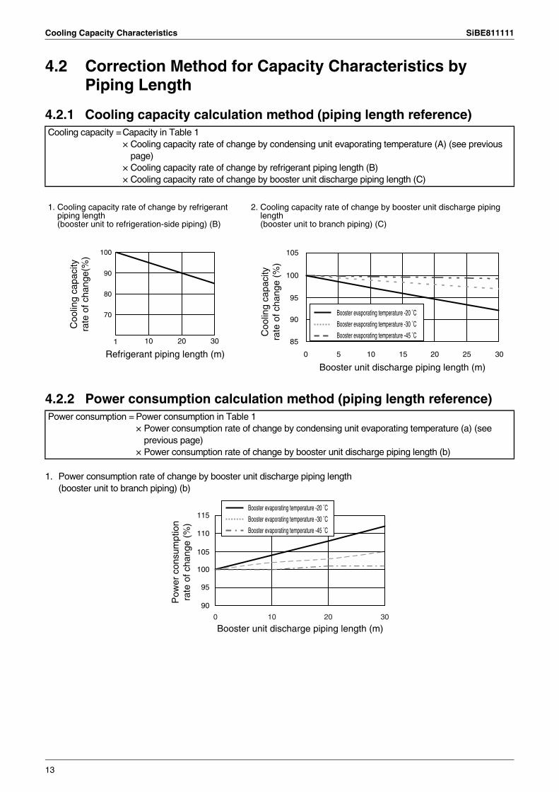
4.2 Correction Method for Capacity Characteristics by Piping Length
4.2.1 Cooling capacity calculation method (piping length reference)
4.2.2 Power consumption calculation method (piping length reference)
1. Power consumption rate of change by booster unit discharge piping length(booster unit to branch piping) (b)
Cooling capacity =Capacity in Table 1× Cooling capacity rate of change by condensing unit evaporating temperature (A) (see previous
page)× Cooling capacity rate of change by refrigerant piping length (B)× Cooling capacity rate of change by booster unit discharge piping length (C)
1. Cooling capacity rate of change by refrigerant piping length(booster unit to refrigeration-side piping) (B)
2. Cooling capacity rate of change by booster unit discharge piping length(booster unit to branch piping) (C)
Power consumption = Power consumption in Table 1× Power consumption rate of change by condensing unit evaporating temperature (a) (see
previous page)× Power consumption rate of change by booster unit discharge piping length (b)
100
90
80
70
10 20 301
Refrigerant piping length (m)
Coo
ling
capa
city
ra
te o
f cha
nge(
%)
Booster unit discharge piping length (m)
105
100
95
90
85
0 5 10 15 20 25 30
Booster evaporating temperature -20 ˚C
Booster evaporating temperature -30 ˚C
Booster evaporating temperature -45 ˚CCoo
ling
capa
city
ra
te o
f cha
nge
(%)
Booster unit discharge piping length (m)
115
110
105
100
95
90
0 10 20 30
Pow
er c
onsu
mpt
ion
rate
of c
hang
e (%
)
Booster evaporating temperature -20 ˚C
Booster evaporating temperature -30 ˚C
Booster evaporating temperature -45 ˚C
13
SiBE811111 Cooling Capacity Characteristics
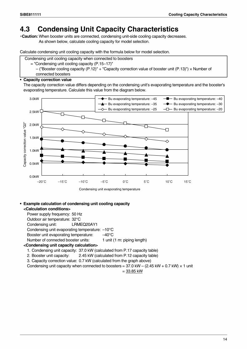
4.3 Condensing Unit Capacity Characteristics∗Caution: When booster units are connected, condensing unit-side cooling capacity decreases.
As shown below, calculate cooling capacity for model selection.
Calculate condensing unit cooling capacity with the formula below for model selection.
• Capacity correction valueThe capacity correction value differs depending on the condensing unit's evaporating temperature and the booster's evaporating temperature. Calculate this value from the diagram below.
• Example calculation of condensing unit cooling capacity<Calculation conditions>
Power supply frequency: 50 HzOutdoor air temperature: 32°CCondensing unit: LRMEQ20AY1Condensing unit evaporating temperature: –10°CBooster unit evaporating temperature: –40°CNumber of connected booster units: 1 unit (1 m: piping length)
<Condensing unit capacity calculation>1. Condensing unit capacity: 37.0 kW (calculated from P.17 capacity table)2. Booster unit capacity: 2.45 kW (calculated from P.12 capacity table)3. Capacity correction value: 0.7 kW (calculated from the graph above)Condensing unit capacity when connected to boosters = 37.0 kW – (2.45 kW + 0.7 kW) × 1 unit
= 33.85 kW
Condensing unit cooling capacity when connected to boosters= "Condensing unit cooling capacity (P.15~17)"
– ("Booster cooling capacity (P.12)" + "Capacity correction value of booster unit (P.13)") × Number of connected boosters
Cap
acity
cor
rect
ion
valu
e "Q
2"
Condensing unit evaporating temperature
3.0kW
2.5kW
2.0kW
1.5kW
1.0kW
0.5kW
0.0kW
Bu evaporating temperature: –45
Bu evaporating temperature: –35
Bu evaporating temperature: –25
Bu evaporating temperature: –40
Bu evaporating temperature: –30
Bu evaporating temperature: –20
–20˚C –15˚C –10˚C –5˚C 0˚C 5˚C 10˚C 15˚C
14
Cooling Capacity Characteristics SiBE811111
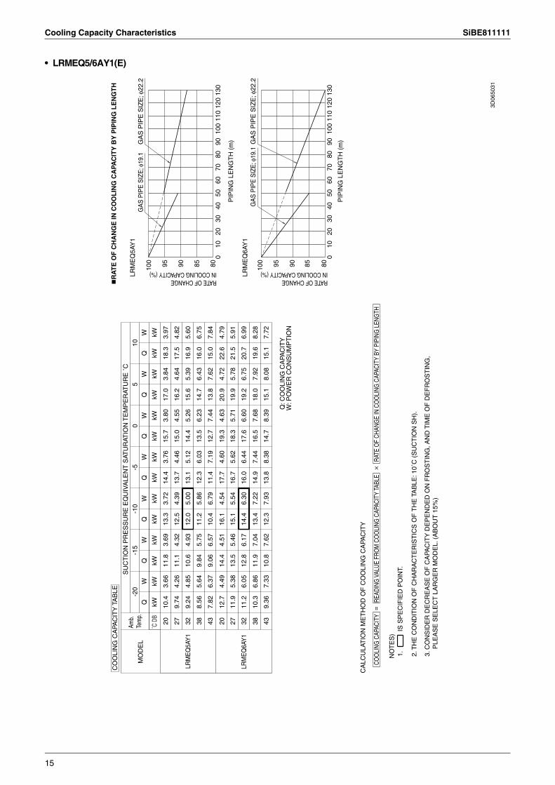
• LRMEQ5/6AY1(E)
3D06
5031
COO
LING
CAP
ACIT
YRA
TE O
F CH
ANG
E IN
CO
OLI
NG C
APAC
ITY
BY P
IPIN
G L
ENG
THRE
ADIN
G V
ALUE
FRO
M C
OO
LING
CAP
ACIT
Y TA
BLE
=
CA
LCU
LAT
ION
ME
TH
OD
OF
CO
OLI
NG
CA
PAC
ITY
050
110
100
4010
7013
012
060
2080
9030
80859095100
LRM
EQ
6AY
1
011
010
040
5013
010
7060
120
8020
9030
7.72
15.1
8.08
15.1
8.39
14.7
8.38
13.8
7.93
12.3
7.62
10.8
7.33
9.36
43
80
8.28
19.6
7.92
18.0
7.68
16.5
7.44
14.9
7.22
13.4
7.04
11.9
6.86
10.3
38
6.99
20.7
6.75
19.2
6.60
17.6
6.44
16.0
6.30
14.4
6.17
12.8
6.05
11.2
32LR
ME
Q6A
Y1
85
5.91
21.5
5.78
19.9
5.71
18.3
5.62
16.7
5.54
15.1
5.46
13.5
5.38
11.9
27
4.79
22.6
4.72
20.9
4.63
19.3
4.60
17.7
4.54
16.1
4.51
14.4
4.49
12.7
20
90
7.84
15.0
7.62
13.8
7.44
12.7
7.19
11.4
6.79
10.4
6.57
9.06
6.37
7.82
43
6.75
16.0
6.43
14.7
6.23
13.5
6.03
12.3
5.86
11.2
5.75
9.84
5.64
8.56
38
5.60
16.9
5.39
15.6
5.26
14.4
5.12
13.1
5.00
12.0
4.93
10.6
4.85
9.24
32
95
LRM
EQ
5AY
1
4.82
17.5
4.64
16.2
4.55
15.0
4.46
13.7
4.39
12.5
4.32
11.1
4.26
9.74
27
3.97
18.3
3.84
17.0
3.80
15.7
3.76
14.4
3.72
13.3
3.69
11.8
3.66
10.4
20
100
kWkW
kWkW
kWkW
kWkW
kWkW
kWkW
kWkW
WW
WW
WW
WQ
LRM
EQ
5AY
1M
OD
EL
0-5
5-1
5-1
010
-20
CO
OLI
NG
CA
PAC
ITY
TA
BLE
Amb.
Te
mp.
˚C D
B
SU
CT
ION
PR
ES
SU
RE
EQ
UIV
ALE
NT
SAT
UR
ATIO
N T
EM
PE
RAT
UR
E ˚
C
Q: C
OO
LIN
G C
APA
CIT
YW
: PO
WE
R C
ON
SU
MP
TIO
N
NO
TE
S)
1.
IS
SP
EC
IFIE
D P
OIN
T.
2. T
HE
CO
ND
ITIO
N O
F C
HA
RA
CT
ER
IST
ICS
OF
TH
E T
AB
LE: 1
0˚C
(S
UC
TIO
N S
H).
3. C
ON
SID
ER
DE
CR
EA
SE
OF
CA
PAC
ITY
DE
PE
ND
ED
ON
FR
OS
TIN
G, A
ND
TIM
E O
F D
EF
RO
ST
ING
, P
LEA
SE
SE
LEC
T L
AR
GE
R M
OD
EL.
(A
BO
UT
15%
)
RA
TE
OF
CH
AN
GE
IN C
OO
LIN
G C
APA
CIT
Y B
Y P
IPIN
G L
EN
GT
H
RATE OF CHANGE IN COOLING CAPACITY (%)
RATE OF CHANGE IN COOLING CAPACITY (%)
GA
S P
IPE
SIZ
E; φ
19.1
GA
S P
IPE
SIZ
E; φ
22.2
GA
S P
IPE
SIZ
E; φ
19.1
GA
S P
IPE
SIZ
E; φ
22.2
PIP
ING
LE
NG
TH
(m
)
PIP
ING
LE
NG
TH
(m
)
×
15
SiBE811111 Cooling Capacity Characteristics
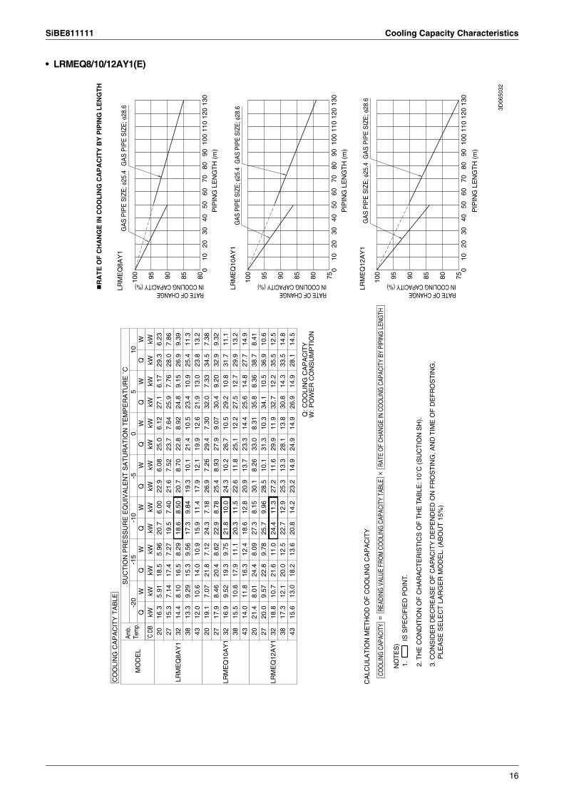
• LRMEQ8/10/12AY1(E)
3D06
5032
PIP
ING
LE
NG
TH
(m
)
010
040
110
5010
7013
060
120
8020
9030
7580859095
COO
LING
CAP
ACIT
YRA
TE O
F CH
ANG
E IN
CO
OLI
NG C
APAC
ITY
BY P
IPIN
G L
ENG
THRE
ADIN
G V
ALUE
FRO
M C
OO
LING
CAP
ACIT
Y TA
BLE
=10
0
CA
LCU
LAT
ION
ME
TH
OD
OF
CO
OLI
NG
CA
PA
CIT
YLR
ME
Q12
AY
1
PIP
ING
LE
NG
TH
(m
)
010
050
4011
070
1013
012
060
2080
3090
7580859095
14.5
28.1
14.9
26.9
14.9
24.9
14.9
23.2
14.2
20.8
13.6
18.2
13.0
15.6
43
100
14.8
33.5
14.3
30.8
13.8
28.1
13.3
25.3
12.9
22.7
12.5
20.0
12.1
17.3
3812
.535
.512
.232
.711
.929
.911
.627
.211
.324
.411
.021
.610
.718
.832
LRM
EQ
12A
Y1
LRM
EQ
10A
Y1
10.6
36.9
10.5
34.1
10.3
31.3
10.1
28.5
9.96
25.7
9.78
22.8
9.57
20.0
278.
4138
.78.
3635
.88.
3133
.08.
2630
.18.
1527
.38.
0924
.48.
0121
.420
14.9
27.7
14.8
25.6
14.4
23.3
13.7
20.9
12.8
18.6
12.4
16.3
11.8
14.0
43
PIP
ING
LE
NG
TH
(m
)
13.2
29.9
12.7
27.5
12.2
25.1
11.8
22.6
11.5
20.3
11.1
17.9
10.8
15.5
38
050
110
100
4070
130
1060
120
8020
9030
11.1
31.7
10.8
29.2
10.5
26.7
10.2
24.3
10.0
21.8
9.75
19.3
9.52
16.9
32LR
ME
Q10
AY
1
80
9.32
32.9
9.20
30.4
9.07
27.9
8.93
25.4
8.78
22.9
8.62
20.4
8.46
17.9
277.
3834
.57.
3332
.07.
3029
.47.
2626
.97.
1824
.37.
1221
.87.
0719
.120
85
13.2
23.8
13.0
21.9
12.6
19.9
12.1
17.9
11.4
15.9
10.9
14.0
10.6
12.0
4311
.325
.410
.923
.410
.521
.410
.119
.39.
8417
.39.
5615
.39.
2913
.338
90
9.39
26.9
9.15
24.8
8.92
22.8
8.70
20.7
8.50
18.6
8.29
16.5
8.10
14.4
32LR
ME
Q8A
Y1
7.86
28.0
7.76
25.9
7.64
23.7
7.52
21.6
7.40
19.5
7.27
17.4
7.14
15.3
276.
2329
.36.
1727
.16.
1225
.06.
0822
.96.
0020
.75.
9618
.55.
9116
.320
95kW
kWkW
kWkW
kWkW
kWkW
kWkW
kWkW
kWW
WW
WW
WW
Q10
0M
OD
EL
05
-20
-5-1
010
-15
SU
CT
ION
PR
ES
SU
RE
EQ
UIV
ALE
NT
SA
TU
RA
TIO
N T
EM
PE
RA
TU
RE
˚C
LRM
EQ
8AY
1C
OO
LIN
G C
AP
AC
ITY
TA
BLE
Amb.
Te
mp.
˚C D
B
Q: C
OO
LIN
G C
AP
AC
ITY
W: P
OW
ER
CO
NS
UM
PT
ION
RA
TE
OF
CH
AN
GE
IN C
OO
LIN
G C
AP
AC
ITY
BY
PIP
ING
LE
NG
TH
RATE OF CHANGE IN COOLING CAPACITY (%)
RATE OF CHANGE IN COOLING CAPACITY (%)
RATE OF CHANGE IN COOLING CAPACITY (%)
GA
S P
IPE
SIZ
E; φ
25.4
GA
S P
IPE
SIZ
E; φ
28.6
GA
S P
IPE
SIZ
E; φ
25.4
GA
S P
IPE
SIZ
E; φ
28.6
GAS
PIP
E SI
ZE; φ
25.4
GAS
PIP
E SI
ZE; φ
28.6
×
NO
TE
S)
1.
IS
SP
EC
IFIE
D P
OIN
T.
2. T
HE
CO
ND
ITIO
N O
F C
HA
RA
CT
ER
IST
ICS
OF
TH
E T
AB
LE: 1
0˚C
(S
UC
TIO
N S
H).
3. C
ON
SID
ER
DE
CR
EA
SE
OF
CA
PAC
ITY
DE
PE
ND
ED
ON
FR
OS
TIN
G, A
ND
TIM
E O
F D
EF
RO
ST
ING
, P
LEA
SE
SE
LEC
T L
AR
GE
R M
OD
EL.
(A
BO
UT
15%
)
16

Cooling Capacity Characteristics SiBE811111
• LRMEQ15/20AY1(E)
=
PIP
ING
LE
NG
TH
(m
)
010
040
5011
070
1013
012
060
2080
9030
7580859095100
LRM
EQ
20AY
1
PIP
ING
LE
NG
TH
(m
)
011
050
4010
013
010
7060
120
2080
3090
19.1
38.1
20.3
38.1
21.4
37.1
21.4
34.5
20.9
31.5
19.9
27.5
19.1
23.5
43
80
21.4
50.2
21.0
47.0
20.2
42.8
19.6
38.5
18.9
34.3
18.4
30.2
17.5
26.0
38
18.5
54.4
17.9
50.0
17.5
45.7
17.0
41.3
16.6
37.0
16.2
32.7
15.8
28.4
32LR
ME
Q20
AY1
85
15.7
56.5
15.4
52.1
15.1
47.7
14.9
43.3
14.6
38.9
14.4
34.5
13.9
30.1
27
12.5
59.3
12.3
54.8
12.2
50.3
12.2
45.8
12.0
41.4
11.9
36.9
11.6
32.3
20
90
20.4
38.8
21.4
38.0
20.9
34.5
19.9
31.0
18.8
27.4
17.9
23.9
17.1
20.5
43
19.3
44.5
18.5
40.8
17.8
37.2
17.2
33.5
16.6
29.9
16.1
26.3
15.6
22.7
38
16.2
47.2
15.7
43.4
15.3
39.7
14.9
35.9
14.5
32.2
14.1
28.5
13.8
24.7
32
95
LRM
EQ
15AY
1
13.6
49.1
13.4
45.3
13.2
41.4
13.0
37.6
12.7
33.9
12.5
30.0
12.3
26.2
27
10.9
51.4
10.7
47.6
10.6
43.7
10.5
39.8
10.4
36.0
10.3
32.0
10.2
28.1
20
100
kWkW
kWkW
kWkW
kWkW
kWkW
kWkW
kWkW
GAS
PIP
E SI
ZE; φ
34.9
GAS
PIP
E SI
ZE; φ
31.8
GAS
PIP
E SI
ZE; φ
34.9
GAS
PIP
E SI
ZE; φ
31.8
WW
WW
WW
WQ
LRM
EQ
15AY
1M
OD
EL
50
10-1
5-1
0-2
0-5
CO
OLI
NG
CA
PAC
ITY
TA
BLE
RA
TE
OF
CH
AN
GE
IN C
OO
LIN
G C
APA
CIT
Y B
Y P
IPIN
G L
EN
GT
H
3D06
5033
Amb.
Te
mp.
SU
CT
ION
PR
ES
SU
RE
EQ
UIV
ALE
NT
SAT
UR
ATIO
N T
EM
PE
RAT
UR
E ˚
C
˚C D
B
Q: C
OO
LIN
G C
APA
CIT
YW
: PO
WE
R C
ON
SU
MP
TIO
N
RATE OF CHANGE IN COOLING CAPACITY (%)
RATE OF CHANGE IN COOLING CAPACITY (%)
COO
LING
CAP
ACIT
YRA
TE O
F CH
ANG
E IN
CO
OLI
NG C
APAC
ITY
BY P
IPIN
G L
ENG
THRE
ADIN
G V
ALUE
FRO
M C
OO
LING
CAP
ACIT
Y TA
BLE
CA
LCU
LAT
ION
ME
TH
OD
OF
CO
OLI
NG
CA
PAC
ITY
NO
TE
S)
1.
IS
SP
EC
IFIE
D P
OIN
T.
2. T
HE
CO
ND
ITIO
N O
F C
HA
RA
CT
ER
IST
ICS
OF
TH
E T
AB
LE: 1
0˚C
(S
UC
TIO
N S
H).
3. C
ON
SID
ER
DE
CR
EA
SE
OF
CA
PAC
ITY
DE
PE
ND
ED
ON
FR
OS
TIN
G, A
ND
TIM
E O
F D
EF
RO
ST
ING
, P
LEA
SE
SE
LEC
T L
AR
GE
R M
OD
EL.
(A
BO
UT
15%
)
×
17
SiBE811111 Cooling Capacity Characteristics
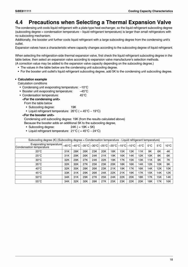
4.4 Precautions when Selecting a Thermal Expansion ValveThe condensing unit cools liquid refrigerant with a plate type heat exchanger, so the liquid refrigerant subcooling degree (subcooling degree = condensation temperature – liquid refrigerant temperature) is larger than small refrigerators with no subcooling mechanism.Additionally, the booster unit further cools liquid refrigerant with a large subcooling degree from the condensing unit's outlet.Expansion valves have a characteristic where capacity changes according to the subcooling degree of liquid refrigerant.
When selecting the refrigeration-side thermal expansion valve, first check the liquid refrigerant subcooling degree in the table below, then select an expansion valve according to expansion valve manufacturer's selection methods.(A correction value may be added to the expansion valve capacity depending on the subcooling degree.)
• The values in the table below are the condensing unit subcooling degree.• For the booster unit outlet's liquid refrigerant subcooling degree, add 5K to the condensing unit subcooling degree.
• Calculation exampleCalculation conditions
• Condensing unit evaporating temperature: –10°C• Booster unit evaporating temperature: –45°C• Condensation temperature: 45°C
<For the condensing unit>From the table below
• Subcooling degree: 19K• Liquid refrigerant temperature: 26°C ( = 45°C – 19°C)
<For the booster unit>Condensing unit subcooling degree: 19K (from the results calculated above)Because the booster adds an additional 5K to the subcooling degree,
• Subcooling degree: 24K ( = 19K + 5K)• Liquid refrigerant temperature: 21°C ( = 45°C – 24°C)
Subcooling degree (K) (Subcooling degree = Condensation temperature - Liquid refrigerant temperature)
Evaporating temperatureCondensation temperature –45°C –40°C –35°C –30°C –25°C –20°C –15°C –10°C –5°C 0°C 5°C 10°C
20°C 31K 28K 26K 23K 20K 18K 15K 13K 11K 9K 6K 4K
25°C 31K 29K 26K 24K 21K 19K 16K 14K 12K 10K 8K 6K
30°C 32K 29K 27K 24K 22K 19K 17K 15K 13K 11K 9K 7K
35°C 32K 30K 27K 25K 23K 20K 18K 16K 14K 12K 10K 9K
40°C 32K 30K 28K 26K 23K 21K 19K 17K 16K 14K 12K 10K
45°C 33K 31K 29K 26K 24K 22K 21K 19K 17K 15K 14K 12K
50°C 34K 31K 29K 27K 25K 24K 22K 20K 18K 17K 15K 14K
55°C 34K 32K 30K 28K 27K 25K 23K 22K 20K 18K 17K 16K
18
External Wiring Diagram SiBE811111
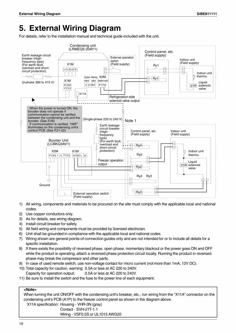
5. External Wiring DiagramFor details, refer to the installation manual and technical guide included with the unit.
1) All wiring, components and materials to be procured on the site must comply with the applicable local and national codes.
2) Use copper conductors only.3) As for details, see wiring diagram.4) Install circuit breaker for safety.5) All field wiring and components must be provided by licensed electrician.6) Unit shall be grounded in compliance with the applicable local and national codes.7) Wiring shown are general points-of-connection guides only and are not intended for or to include all details for a
specific installation.8) If there exists the possibility of reversed phase, open phase, momentary blackout or the power goes ON and OFF
while the product is operating, attach a reversed phase protection circuit locally. Running the product in reversed phase may break the compressor and other parts.
9) In case of used remote switch, use non-voltage contact for micro current (not more than 1mA, 12V DC).10) Total capacity for caution, warning: 0.5A or less at AC 220 to 240V.
Capacity for operation output: 0.5A or less at AC 220 to 240V.11) Be sure to install the switch and the fuse to the power line of each equipment.
<Note>When turning the unit ON/OFF with the condensing unit's breaker, etc., run wiring from the "X11A" connector on the condensing unit's PCB (A1P) to the freezer control panel as shown in the diagram above.
X11A specification: Housing - VHR-3N (gray) Contact - SVH-21T-1.1Wiring - VSF0.5S or UL1015 AWG20
Ry1
Ry1
21R
21R
X1M
X2MX1M
X11A
L3
C C1W1 P2F2
In-Out
N
T2F2 1 2 L N
X1M
Earth leakage circuit breaker (High-frequency type)(For earth fault, overload and short-circuit protection)
(3-phase 380 to 415 V)
Condensing unit (LRMEQ5-20AY1)
External operation switch(Field supply)
L1 L2
Caution output
Warning output Operation output
P1F1
Control panel, etc. (Field supply)
Indoor unit (Field supply)
Indoor unit thermo.
Liquid solenoid valve
Refrigeration-side solenoid valve output
When the power is turned ON, the booster does not operate if communication cannot be verified between the condensing unit and the booster. (See P.26)If communication is verified, "H6P"
illuminates on the condensing unit's control PCB. (See P.21-22)
Booster Unit (LCBKQ3AV1)
X2MF1 T1 S1 S2
External operation switch (Field supply)
Freezer operation output
Earth leakage circuit breaker (High-frequency type)(For earth fault, overload and short-circuit protection)
Control panel, etc. (Field supply)
Ry4
Indoor unit (Field supply)
Liquid solenoid valve
Indoor unit thermo.
Ry3
Ry3
Ry2
Ry2
Ry4
Ground
(Single-phase 220 to 240 V) Note 1
19
SiBE811111 Inspection & Refrigerant Charging Methods
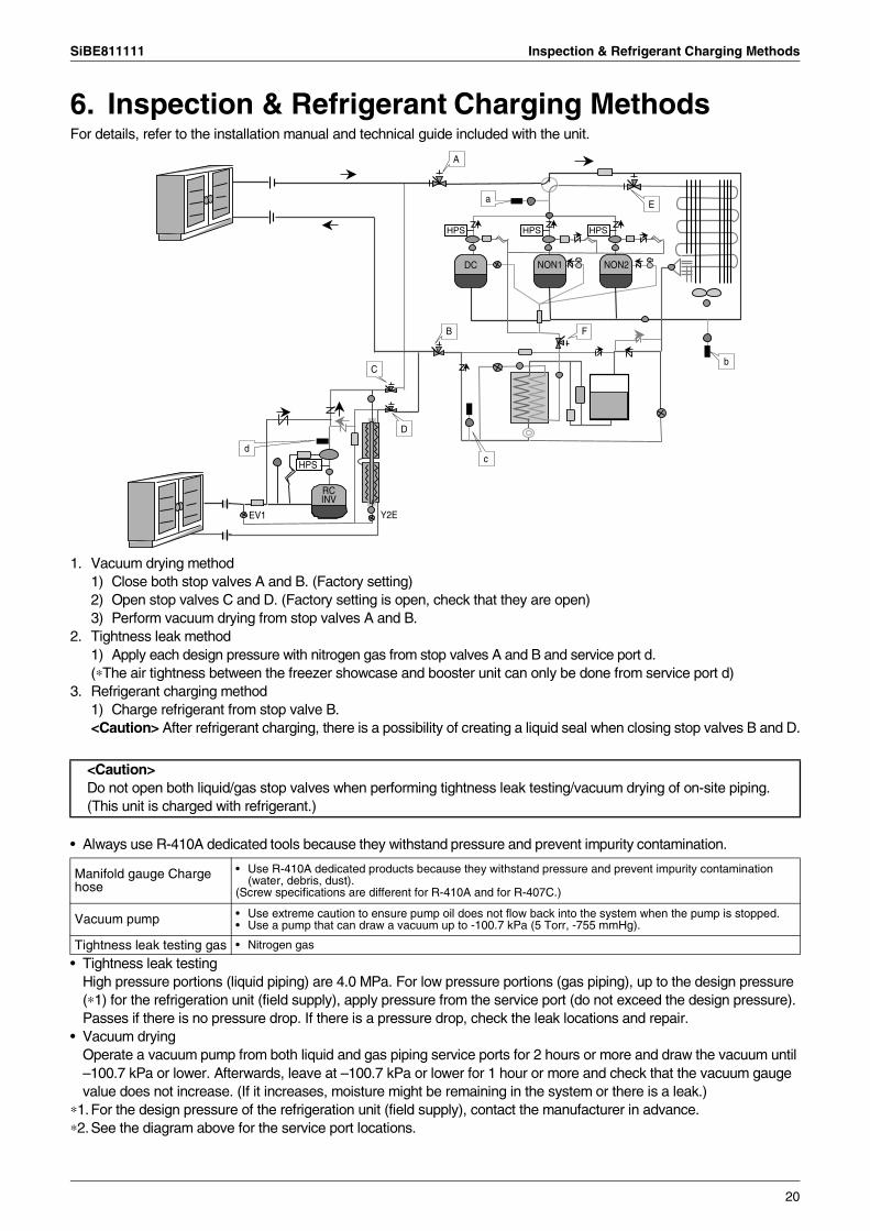
6. Inspection & Refrigerant Charging MethodsFor details, refer to the installation manual and technical guide included with the unit.
1. Vacuum drying method1) Close both stop valves A and B. (Factory setting)2) Open stop valves C and D. (Factory setting is open, check that they are open)3) Perform vacuum drying from stop valves A and B.
2. Tightness leak method1) Apply each design pressure with nitrogen gas from stop valves A and B and service port d.(∗The air tightness between the freezer showcase and booster unit can only be done from service port d)
3. Refrigerant charging method1) Charge refrigerant from stop valve B.<Caution> After refrigerant charging, there is a possibility of creating a liquid seal when closing stop valves B and D.
• Always use R-410A dedicated tools because they withstand pressure and prevent impurity contamination.
• Tightness leak testingHigh pressure portions (liquid piping) are 4.0 MPa. For low pressure portions (gas piping), up to the design pressure (∗1) for the refrigeration unit (field supply), apply pressure from the service port (do not exceed the design pressure). Passes if there is no pressure drop. If there is a pressure drop, check the leak locations and repair.
• Vacuum dryingOperate a vacuum pump from both liquid and gas piping service ports for 2 hours or more and draw the vacuum until –100.7 kPa or lower. Afterwards, leave at –100.7 kPa or lower for 1 hour or more and check that the vacuum gauge value does not increase. (If it increases, moisture might be remaining in the system or there is a leak.)
∗1.For the design pressure of the refrigeration unit (field supply), contact the manufacturer in advance.∗2.See the diagram above for the service port locations.
A
a E
b
FB
C
d
HPS
D
c
RCINV
EV1 Y2E
HPS HPS HPS
DC NON1 NON2
<Caution>Do not open both liquid/gas stop valves when performing tightness leak testing/vacuum drying of on-site piping. (This unit is charged with refrigerant.)
Manifold gauge Charge hose
• Use R-410A dedicated products because they withstand pressure and prevent impurity contamination (water, debris, dust).
(Screw specifications are different for R-410A and for R-407C.)
Vacuum pump • Use extreme caution to ensure pump oil does not flow back into the system when the pump is stopped.• Use a pump that can draw a vacuum up to -100.7 kPa (5 Torr, -755 mmHg).
Tightness leak testing gas • Nitrogen gas
20
Test Operation Method SiBE811111
7. Test Operation MethodFor details, refer to the installation manual and technical guide included with the unit.
• Verification before turning ON the power supply1. Check that the target evaporating temperature for the condensing unit and booster units is set.2. Set the condensing unit gas-side stop valve/liquid-side stop valve to "Full Open".3. Check that the system is wired according to the external wiring diagram.
• Freezer operation input • Refrigeration-side operating output• Freezer operation output • Booster unit - condensing unit communication line
4. Check that the piping covers/El. compo. box covers for the condensing unit, booster units, and refrigeration units are shut, then turn ON the power supply.
5. When the system has been changed from the initial test operation, such as a change in the number of connected booster units, press and hold the BS button BS5 for 5 seconds. It is not necessary to press this button for the initial test operation.
• Condensing unit operation6. Turn "ON" the condensing unit operation switch.7. Check the seal state with the condensing unit sight glass.8. If the system lacks refrigerant, check if the specified amount of refrigerant is in the system, add more if insufficient.9. Check that the load-side (refrigerator) liquid solenoid valve control is being used with "Refrigeration-side operating
output" from the condensing unit.10.Check that compression operates when the condensing unit suction pressure is a low pressure ON value or
higher.11.Check that compression stops when the condensing unit suction pressure is a low pressure OFF value or lower.
• Booster unit operation12.Check that 4 on the condensing unit DS2 is switched to the OFF side.13.Turn "ON" the booster unit operation switch.14.Check that the load-side (freezer) liquid solenoid valve control is being used with "Freezer operation output" from
the booster unit.15.Check that the booster unit operates the compressor if the refrigeration-side thermo. is ON and the booster suction
pressure is a low pressure ON value or higher.
• Final verification16.Check that the target evaporating temperature for both the condensing unit and booster units is set without errors.17.Check that the condensing unit "H3P, H6P" LEDs are ON.18.Check if the low pressure saturation temperature becomes the target evaporating temperature for both the
condensing unit and booster units.19.Check that the booster unit suction pipe temperature is 20°C or lower and that suction superheated degree is 10K
or more.20.Check that suction pipe SH of the condensing unit refrigeration-side outlet's main pipe (piping after merging with
refrigeration-side equipment) is 10K or higher and 30K or lower.
• Precautions21.With the booster unit running, do not turn OFF the condensing unit operation switch and do not turn OFF the
power supply.(This can damage the compressor.)
21

SiBE811111 Test Operation Method
∗1 Refrigeration-side liquid solenoid valve control specification1. Condition where the refrigeration-side liquid solenoid valve
opensRefrigeration-side liquid solenoid valve output: ONRefrigeration thermo.: ON
2. Condition where the refrigeration-side liquid solenoid valve closes
Refrigeration-side liquid solenoid valve output: OFFRefrigeration thermo.: OFF
∗2 Refrigeration-side liquid solenoid valve control specification1. Condition where the refrigeration-side liquid
solenoid valve opensFreezer operation output: ONRefrigeration thermo.: ON
2. Condition where the refrigeration-side liquid solenoid valve closes
Freezer operation output: OFFRefrigeration thermo.: OFF
&
&
&
&
Booster
Outdoor unit
Freezer load
Refrigerator load
Refrigerator load
Inspection door (right)(Upper-right section of el. compo. box)
BS1
MODE
BS2
SET
BS3
RETURN
BS4 BS5
RESET
LED display
Suction pipe SH on the refrigeration-side is within the range below before the branch 10 ≤ suction pipe SH ≤ 30K
El. compo. box lid
Check that H3P and H6P are ON
Lift up the tab to open the cover
Inspection door cover (right)
DIP switches (DS1, DS2)
BS button(BS1 through BS5)
LED(H1P to H7P)
H1P H2P H3P H4P H5P H6P H7P
:OFF :ON :Blinking
22
Service Diagnosis SiBE811111
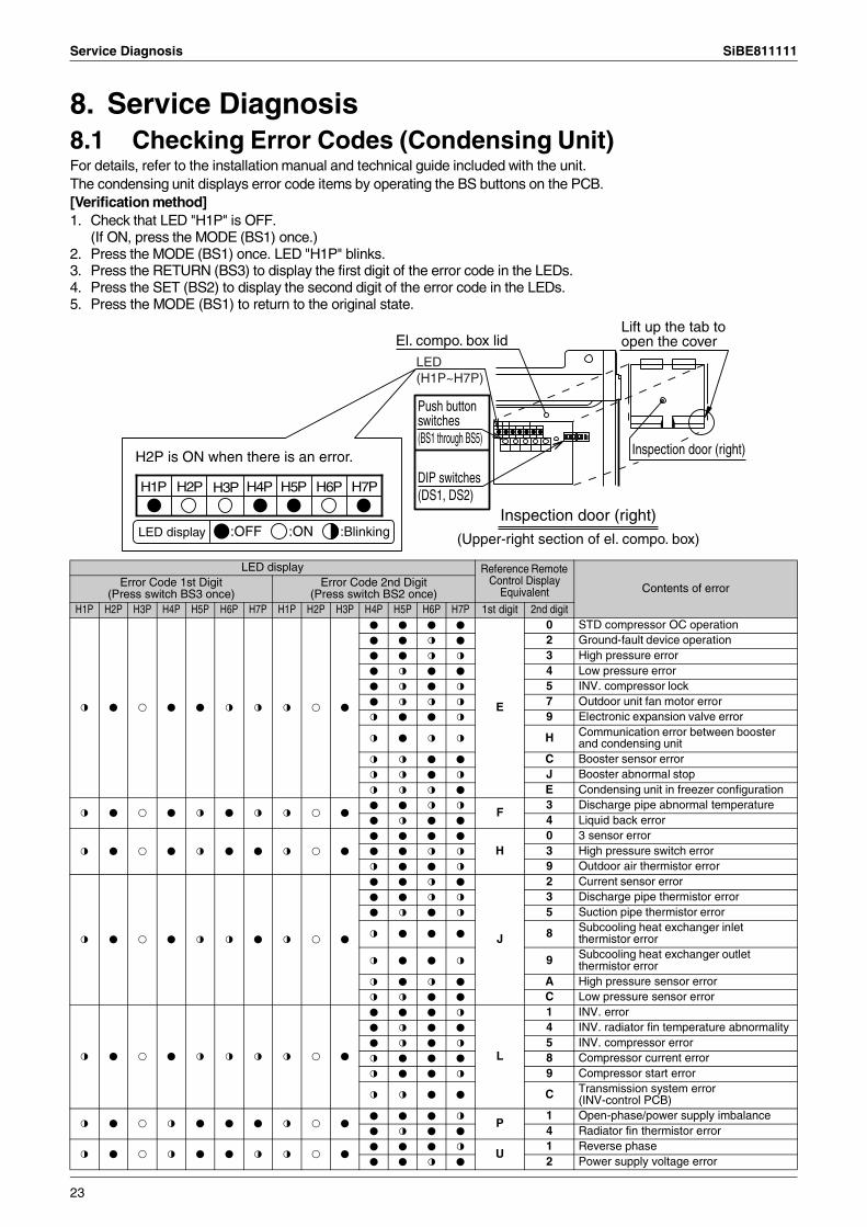
8. Service Diagnosis8.1 Checking Error Codes (Condensing Unit)For details, refer to the installation manual and technical guide included with the unit.The condensing unit displays error code items by operating the BS buttons on the PCB.[Verification method]1. Check that LED "H1P" is OFF.
(If ON, press the MODE (BS1) once.)2. Press the MODE (BS1) once. LED "H1P" blinks.3. Press the RETURN (BS3) to display the first digit of the error code in the LEDs.4. Press the SET (BS2) to display the second digit of the error code in the LEDs.5. Press the MODE (BS1) to return to the original state.
H2P is ON when there is an error. Inspection door (right)
Inspection door (right)
(Upper-right section of el. compo. box)
El. compo. box lid
LED display
Lift up the tab to open the cover
Push button switches(BS1 through BS5)
DIP switches (DS1, DS2)
H1P H2P H3P H4P H5P H6P H7P
:OFF :ON :Blinking
LED (H1P~H7P)
LED display Reference Remote Control Display
Equivalent Contents of errorError Code 1st Digit (Press switch BS3 once)
Error Code 2nd Digit(Press switch BS2 once)
H1P H2P H3P H4P H5P H6P H7P H1P H2P H3P H4P H5P H6P H7P 1st digit 2nd digit
l h k h h l l l k h
h h h h
E
0 STD compressor OC operationh h l h 2 Ground-fault device operationh h l l 3 High pressure errorh l h h 4 Low pressure errorh l h l 5 INV. compressor lockh l l l 7 Outdoor unit fan motor errorl h h l 9 Electronic expansion valve error
l h l l H Communication error between booster and condensing unit
l l h h C Booster sensor errorl l h l J Booster abnormal stopl l l h E Condensing unit in freezer configuration
l h k h l h l l k hh h l l
F3 Discharge pipe abnormal temperature
h l h h 4 Liquid back error
l h k h l h h l k h
h h h h
H0 3 sensor error
h h l l 3 High pressure switch errorl h h l 9 Outdoor air thermistor error
l h k h l l h l k h
h h l h
J
2 Current sensor errorh h l l 3 Discharge pipe thermistor errorh l h l 5 Suction pipe thermistor error
l h h h 8 Subcooling heat exchanger inlet thermistor error
l h h l 9 Subcooling heat exchanger outlet thermistor error
l h l h A High pressure sensor errorl l h h C Low pressure sensor error
l h k h l l l l k h
h h h l
L
1 INV. errorh l h h 4 INV. radiator fin temperature abnormalityh l h l 5 INV. compressor errorl h h h 8 Compressor current errorl h h l 9 Compressor start error
l l h h C Transmission system error(INV-control PCB)
l h k l h h h l k hh h h l
P1 Open-phase/power supply imbalance
h l h h 4 Radiator fin thermistor error
l h k l h h l l k hh h h l
U1 Reverse phase
h h l h 2 Power supply voltage error
23
SiBE811111 Service Diagnosis
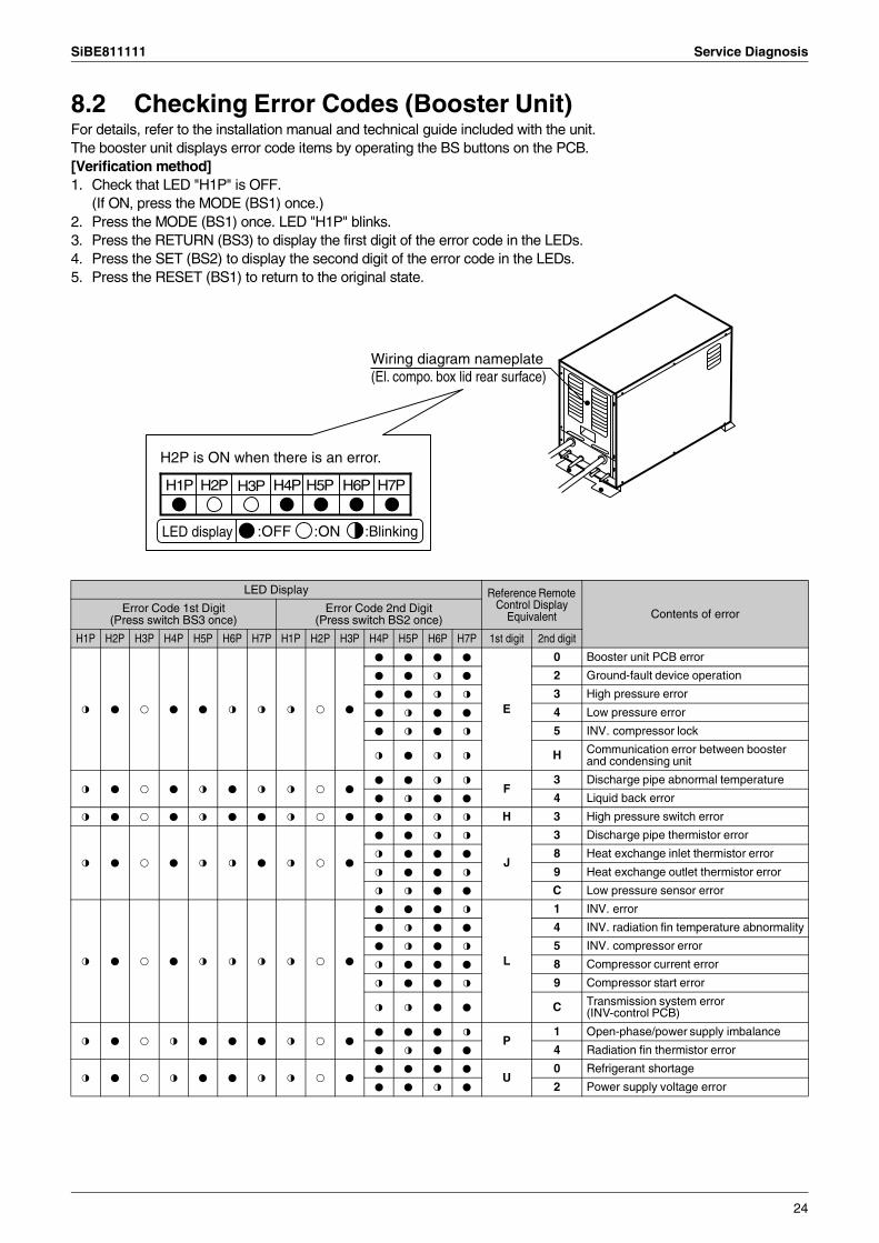
8.2 Checking Error Codes (Booster Unit)For details, refer to the installation manual and technical guide included with the unit.The booster unit displays error code items by operating the BS buttons on the PCB.[Verification method]1. Check that LED "H1P" is OFF.
(If ON, press the MODE (BS1) once.)2. Press the MODE (BS1) once. LED "H1P" blinks.3. Press the RETURN (BS3) to display the first digit of the error code in the LEDs.4. Press the SET (BS2) to display the second digit of the error code in the LEDs.5. Press the RESET (BS1) to return to the original state.
H2P is ON when there is an error.
LED display
Wiring diagram nameplate (El. compo. box lid rear surface)
H1P H2P H3P H4P H5P H6P H7P
:OFF :ON :Blinking
LED Display Reference Remote Control Display
Equivalent Contents of errorError Code 1st Digit(Press switch BS3 once)
Error Code 2nd Digit(Press switch BS2 once)
H1P H2P H3P H4P H5P H6P H7P H1P H2P H3P H4P H5P H6P H7P 1st digit 2nd digit
l h k h h l l l k h
h h h h
E
0 Booster unit PCB error
h h l h 2 Ground-fault device operation
h h l l 3 High pressure error
h l h h 4 Low pressure error
h l h l 5 INV. compressor lock
l h l l H Communication error between booster and condensing unit
l h k h l h l l k hh h l l
F3 Discharge pipe abnormal temperature
h l h h 4 Liquid back error
l h k h l h h l k h h h l l H 3 High pressure switch error
l h k h l l h l k h
h h l l
J
3 Discharge pipe thermistor error
l h h h 8 Heat exchange inlet thermistor error
l h h l 9 Heat exchange outlet thermistor error
l l h h C Low pressure sensor error
l h k h l l l l k h
h h h l
L
1 INV. error
h l h h 4 INV. radiation fin temperature abnormality
h l h l 5 INV. compressor error
l h h h 8 Compressor current error
l h h l 9 Compressor start error
l l h h C Transmission system error(INV-control PCB)
l h k l h h h l k hh h h l
P1 Open-phase/power supply imbalance
h l h h 4 Radiation fin thermistor error
l h k l h h l l k hh h h h
U0 Refrigerant shortage
h h l h 2 Power supply voltage error
24
Service Diagnosis SiBE811111
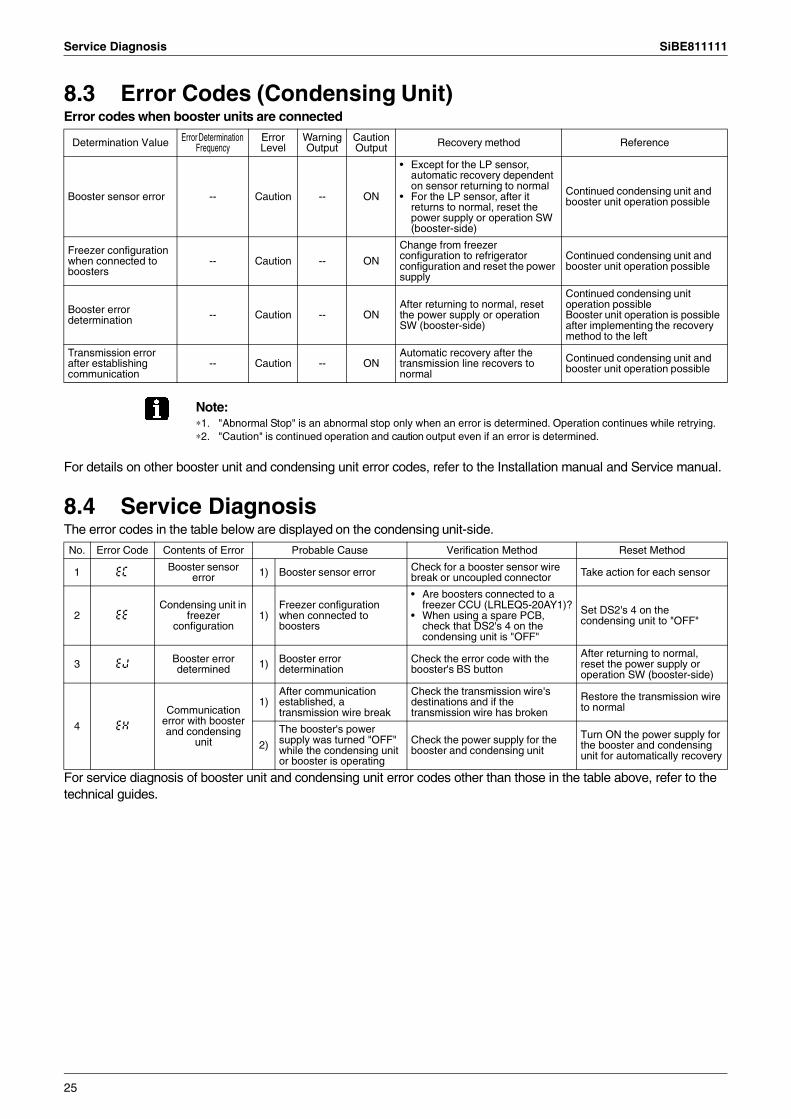
8.3 Error Codes (Condensing Unit)Error codes when booster units are connected
Note:∗1. "Abnormal Stop" is an abnormal stop only when an error is determined. Operation continues while retrying.∗2. "Caution" is continued operation and caution output even if an error is determined.
For details on other booster unit and condensing unit error codes, refer to the Installation manual and Service manual.
8.4 Service DiagnosisThe error codes in the table below are displayed on the condensing unit-side.
For service diagnosis of booster unit and condensing unit error codes other than those in the table above, refer to the technical guides.
Determination Value Error Determination Frequency
Error Level
Warning Output
Caution Output Recovery method Reference
Booster sensor error -- Caution -- ON
• Except for the LP sensor, automatic recovery dependent on sensor returning to normal
• For the LP sensor, after it returns to normal, reset the power supply or operation SW (booster-side)
Continued condensing unit and booster unit operation possible
Freezer configuration when connected to boosters
-- Caution -- ON
Change from freezer configuration to refrigerator configuration and reset the power supply
Continued condensing unit and booster unit operation possible
Booster error determination -- Caution -- ON
After returning to normal, reset the power supply or operation SW (booster-side)
Continued condensing unit operation possibleBooster unit operation is possible after implementing the recovery method to the left
Transmission error after establishing communication
-- Caution -- ONAutomatic recovery after the transmission line recovers to normal
Continued condensing unit and booster unit operation possible
No. Error Code Contents of Error Probable Cause Verification Method Reset Method
1 EC Booster sensor error 1) Booster sensor error Check for a booster sensor wire
break or uncoupled connector Take action for each sensor
2 EECondensing unit in
freezer configuration
1)Freezer configuration when connected to boosters
• Are boosters connected to a freezer CCU (LRLEQ5-20AY1)?
• When using a spare PCB, check that DS2's 4 on the condensing unit is "OFF"
Set DS2's 4 on the condensing unit to "OFF"
3 EJ Booster error determined 1) Booster error
determinationCheck the error code with the booster's BS button
After returning to normal, reset the power supply or operation SW (booster-side)
4 EH
Communication error with booster and condensing
unit
1)After communication established, a transmission wire break
Check the transmission wire's destinations and if the transmission wire has broken
Restore the transmission wire to normal
2)
The booster's power supply was turned "OFF" while the condensing unit or booster is operating
Check the power supply for the booster and condensing unit
Turn ON the power supply for the booster and condensing unit for automatically recovery
25
SiBE811111 Service Diagnosis
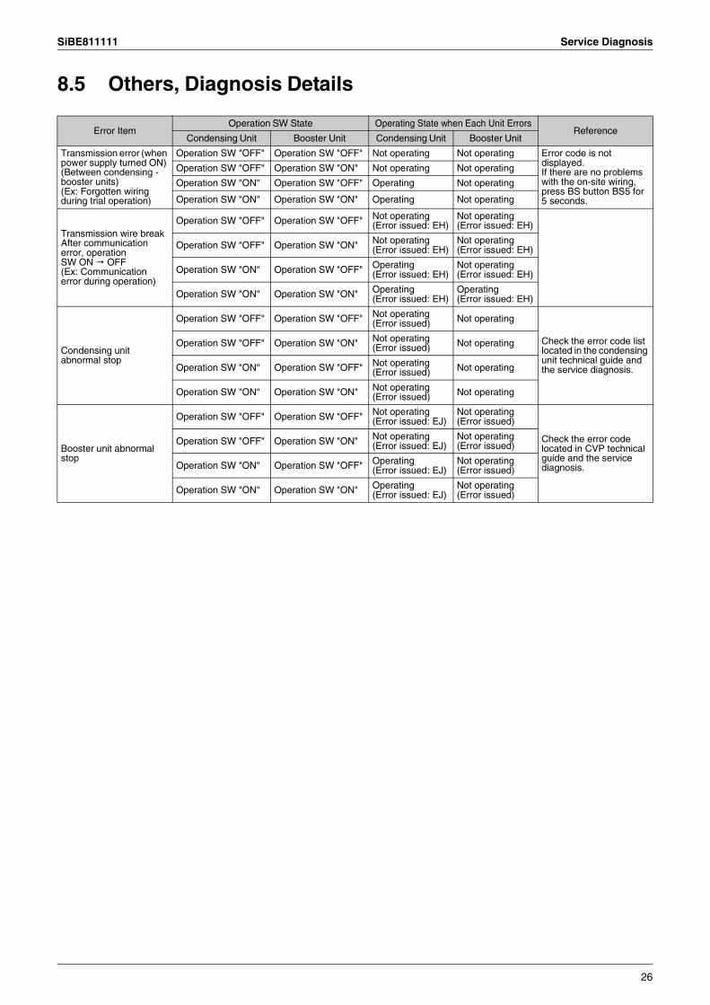
8.5 Others, Diagnosis Details
Error ItemOperation SW State Operating State when Each Unit Errors
ReferenceCondensing Unit Booster Unit Condensing Unit Booster Unit
Transmission error (when power supply turned ON) (Between condensing - booster units)(Ex: Forgotten wiring during trial operation)
Operation SW "OFF" Operation SW "OFF" Not operating Not operating Error code is not displayed.If there are no problems with the on-site wiring, press BS button BS5 for 5 seconds.
Operation SW "OFF" Operation SW "ON" Not operating Not operating
Operation SW "ON" Operation SW "OFF" Operating Not operating
Operation SW "ON" Operation SW "ON" Operating Not operating
Transmission wire break After communication error, operationSW ON OFF(Ex: Communication error during operation)
Operation SW "OFF" Operation SW "OFF" Not operating(Error issued: EH)
Not operating (Error issued: EH)
Operation SW "OFF" Operation SW "ON" Not operating(Error issued: EH)
Not operating (Error issued: EH)
Operation SW "ON" Operation SW "OFF" Operating(Error issued: EH)
Not operating (Error issued: EH)
Operation SW "ON" Operation SW "ON" Operating(Error issued: EH)
Operating(Error issued: EH)
Condensing unit abnormal stop
Operation SW "OFF" Operation SW "OFF" Not operating (Error issued) Not operating
Check the error code list located in the condensing unit technical guide and the service diagnosis.
Operation SW "OFF" Operation SW "ON" Not operating (Error issued) Not operating
Operation SW "ON" Operation SW "OFF" Not operating (Error issued) Not operating
Operation SW "ON" Operation SW "ON" Not operating (Error issued) Not operating
Booster unit abnormal stop
Operation SW "OFF" Operation SW "OFF" Not operating (Error issued: EJ)
Not operating (Error issued)
Check the error code located in CVP technical guide and the service diagnosis.
Operation SW "OFF" Operation SW "ON" Not operating (Error issued: EJ)
Not operating (Error issued)
Operation SW "ON" Operation SW "OFF" Operating(Error issued: EJ)
Not operating (Error issued)
Operation SW "ON" Operation SW "ON" Operating(Error issued: EJ)
Not operating (Error issued)
26
Service Diagnosis SiBE811111
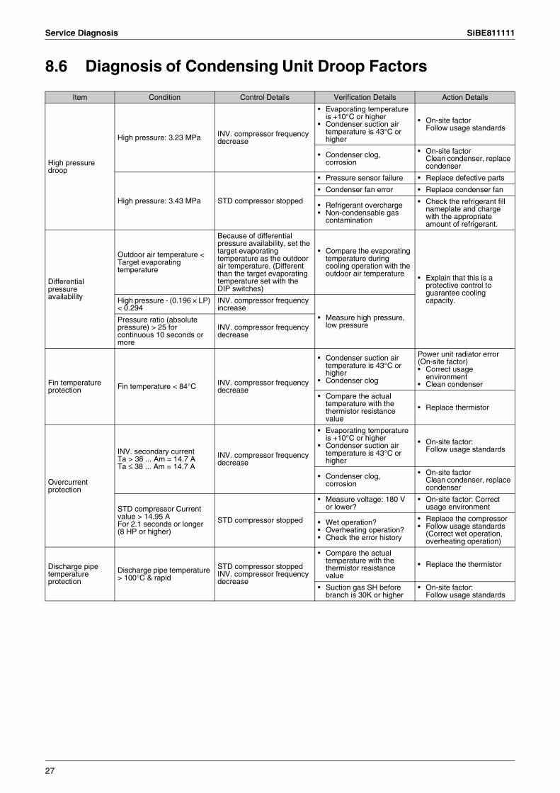
8.6 Diagnosis of Condensing Unit Droop Factors
Item Condition Control Details Verification Details Action Details
High pressure droop
High pressure: 3.23 MPa INV. compressor frequency decrease
• Evaporating temperature is +10°C or higher
• Condenser suction air temperature is 43°C or higher
• On-site factorFollow usage standards
• Condenser clog, corrosion
• On-site factorClean condenser, replace condenser
High pressure: 3.43 MPa STD compressor stopped
• Pressure sensor failure • Replace defective parts
• Condenser fan error • Replace condenser fan
• Refrigerant overcharge• Non-condensable gas
contamination
• Check the refrigerant fill nameplate and charge with the appropriate amount of refrigerant.
Differential pressure availability
Outdoor air temperature < Target evaporating temperature
Because of differential pressure availability, set the target evaporating temperature as the outdoor air temperature. (Different than the target evaporating temperature set with the DIP switches)
• Compare the evaporating temperature during cooling operation with the outdoor air temperature • Explain that this is a
protective control to guarantee cooling capacity.High pressure - (0.196 × LP)
< 0.294INV. compressor frequency increase
• Measure high pressure, low pressure
Pressure ratio (absolute pressure) > 25 for continuous 10 seconds or more
INV. compressor frequency decrease
Fin temperature protection Fin temperature < 84°C INV. compressor frequency
decrease
• Condenser suction air temperature is 43°C or higher
• Condenser clog
Power unit radiator error(On-site factor)• Correct usage
environment• Clean condenser
• Compare the actual temperature with the thermistor resistance value
• Replace thermistor
Overcurrent protection
INV. secondary current Ta > 38 ... Am = 14.7 A Ta ≤ 38 ... Am = 14.7 A
INV. compressor frequency decrease
• Evaporating temperature is +10°C or higher
• Condenser suction air temperature is 43°C or higher
• On-site factor:Follow usage standards
• Condenser clog, corrosion
• On-site factorClean condenser, replace condenser
STD compressor Current value > 14.95 AFor 2.1 seconds or longer (8 HP or higher)
STD compressor stopped
• Measure voltage: 180 V or lower?
• On-site factor: Correct usage environment
• Wet operation?• Overheating operation?• Check the error history
• Replace the compressor• Follow usage standards
(Correct wet operation, overheating operation)
Discharge pipe temperature protection
Discharge pipe temperature > 100°C & rapid
STD compressor stoppedINV. compressor frequency decrease
• Compare the actual temperature with the thermistor resistance value
• Replace the thermistor
• Suction gas SH before branch is 30K or higher
• On-site factor:Follow usage standards
27
SiBE811111 Reference Data
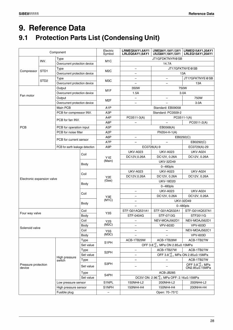
9. Reference Data9.1 Protection Parts List (Condensing Unit)
Component Electric Symbol
LRMEQ5AY1,6AY1 LRLEQ5AY1,6AY1
LRMEQ8AY1,10AY1,12AY1 LRLEQ8AY1,10AY1,12AY1
LRMEQ15AY1,20AY1 LRLEQ15AY1,20AY1
Compressor
INV.Type
M1CJT1GFDKTNYR@SB
Overcurrent protection device 14.7A
STD1Type
M2C– JT17GFKTNYE@SB
Overcurrent protection device – 13A
STD2Type
M3C– – JT17GFKTNYE@SB
Overcurrent protection device – – 13A
Fan motor
OutputM1F
350W 750W
Overcurrent protection device 1.5A 3.0A
OutputM2F
– – 750W
Overcurrent protection device – – 3.0A
PCB
Main PCB A1P Standard: EB09058
PCB for compressor INV. A3P Standard: PC0509-2
PCB for fan INV.A4P PC0511-3(A) PC0511-1(A)
A8P – – PC0511-2(A)
PCB for operation input A5P EB0568(A)
PCB for noise filter A2P FN354-H-1(A)
PCB for current sensorA6P – EB0292(C)
A7P – – EB0292(C)
PCB for earth leakage detection A9P EC0726(A)-9 EC0729(A)-29
Electronic expansion valve
CoilY1E
(Main)
UKV-A023 UKV-A023 UKV-A024
DC12V,0.26A DC12V, 0.26A DC12V, 0.26A
BodyUKV-32D49
0~480pls
CoilY2E
(Gas)
UKV-A023 UKV-A023 UKV-A024
DC12V,0.26A DC12V, 0.26A DC12V, 0.26A
BodyUKV-18D20
0~480pls
CoilY3E
(M1C)
– UKV-A023 UKV-A024
– DC12V, 0.26A DC12V, 0.26A
Body– UKV-32D49
– 0~480pls
Four way valveCoil
Y3SSTF-G01AQ531A1 STF-G01AQ532A1 STF-G01AQ537A1
Body STF-0404G STF-0713G STF2011G
Solenoid valve
Coil Y2S(M2C)
– NEV-MOAJ562D1 NEV-MOAJ562D1
Body – VPV-603D VPV-603D
Coil Y5S(M3C)
– – NEV-MOAJ562C1
Body – – VPV-603D
Pressure protection device
High pressure switch
TypeS1PH
ACB-1TB29W ACB-1TB28W ACB-1TB27W
Set value OFF 3.8 MPa ON 2.85±0.15MPa
TypeS2PH
– ACB-1TB27W ACB-1TB27W
Set value – OFF 3.8 MPa ON 2.85±0.15MPa
TypeS3PH
– – ACB-1TB27W
Set value – – OFF 3.8 MPaON2.85±0.15MPa
TypeS4PH
ACB-JB285
Set value DC5V ON: 2.96 MPa OFF: 2.16±0.15MPa
Low pressure sensor S1NPL 150NH4-L2 200NH4-L2 200NH4-L2
High pressure sensor S1NPH 150NH4-H4 150NH4-H4 200NH4-H4
Fusible plug – Open: 70~75°C
+0–0.1
+0–0.1
+0–0.1
+0- 0.1
28
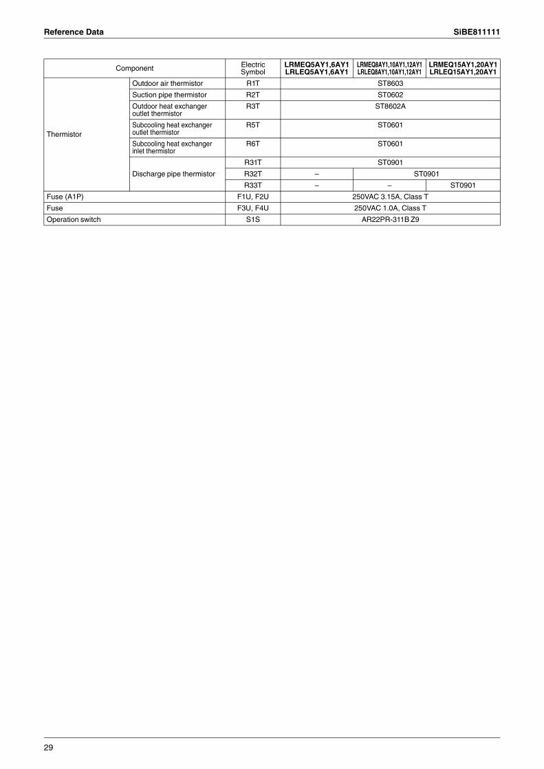
Reference Data SiBE811111
Thermistor
Outdoor air thermistor R1T ST8603
Suction pipe thermistor R2T ST0602
Outdoor heat exchanger outlet thermistor
R3T ST8602A
Subcooling heat exchanger outlet thermistor
R5T ST0601
Subcooling heat exchanger inlet thermistor
R6T ST0601
Discharge pipe thermistor
R31T ST0901
R32T – ST0901
R33T – – ST0901
Fuse (A1P) F1U, F2U 250VAC 3.15A, Class T
Fuse F3U, F4U 250VAC 1.0A, Class T
Operation switch S1S AR22PR-311B Z9
Component Electric Symbol
LRMEQ5AY1,6AY1 LRLEQ5AY1,6AY1
LRMEQ8AY1,10AY1,12AY1 LRLEQ8AY1,10AY1,12AY1
LRMEQ15AY1,20AY1 LRLEQ15AY1,20AY1
29
SiBE811111 Reference Data
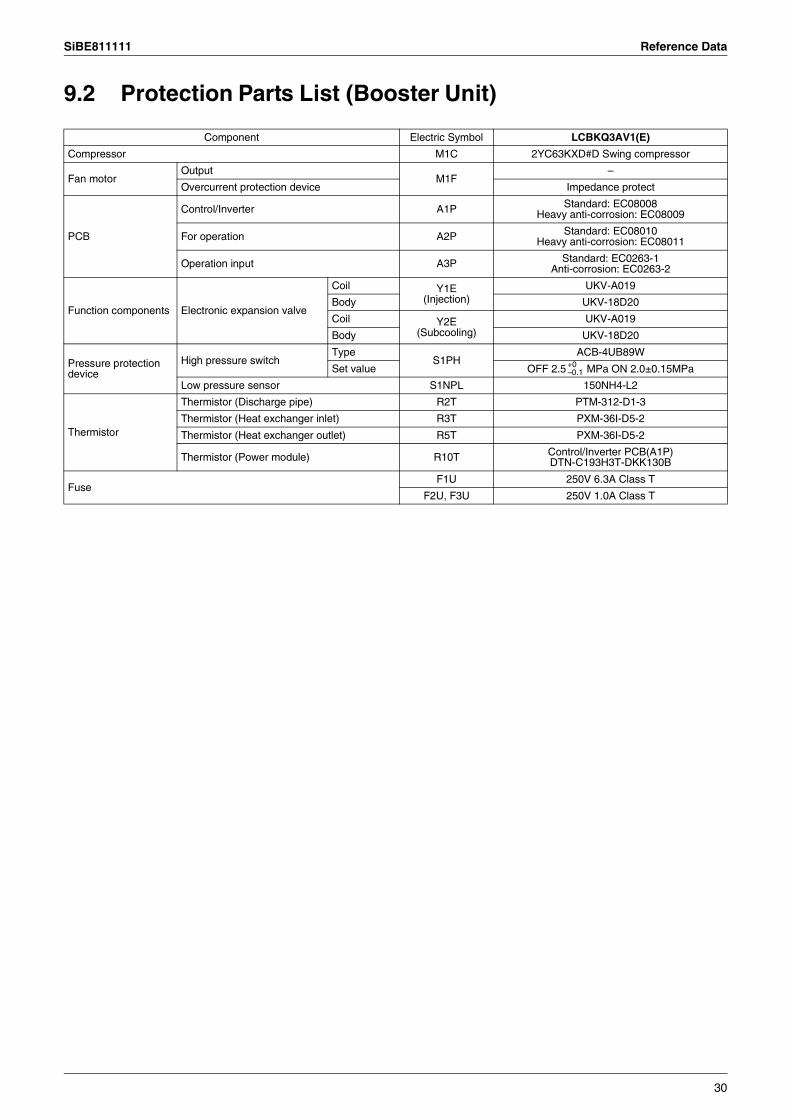
9.2 Protection Parts List (Booster Unit)
Component Electric Symbol LCBKQ3AV1(E)
Compressor M1C 2YC63KXD#D Swing compressor
Fan motorOutput
M1F–
Overcurrent protection device Impedance protect
PCB
Control/Inverter A1P Standard: EC08008Heavy anti-corrosion: EC08009
For operation A2P Standard: EC08010Heavy anti-corrosion: EC08011
Operation input A3P Standard: EC0263-1Anti-corrosion: EC0263-2
Function components Electronic expansion valve
Coil Y1E(Injection)
UKV-A019
Body UKV-18D20
Coil Y2E(Subcooling)
UKV-A019
Body UKV-18D20
Pressure protection device
High pressure switchType
S1PHACB-4UB89W
Set value OFF 2.5 MPa ON 2.0±0.15MPa
Low pressure sensor S1NPL 150NH4-L2
Thermistor
Thermistor (Discharge pipe) R2T PTM-312-D1-3
Thermistor (Heat exchanger inlet) R3T PXM-36I-D5-2
Thermistor (Heat exchanger outlet) R5T PXM-36I-D5-2
Thermistor (Power module) R10T Control/Inverter PCB(A1P)DTN-C193H3T-DKK130B
FuseF1U 250V 6.3A Class T
F2U, F3U 250V 1.0A Class T
+0–0.1
30
Reference Data SiBE811111
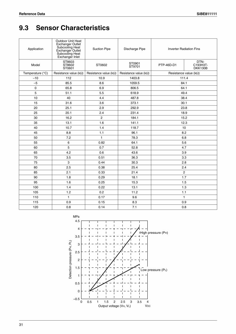
9.3 Sensor Characteristics
Application
Outdoor Unit Heat Exchanger Outlet Subcooling Heat Exchanger Outlet Subcooling Heat Exchanger Inlet
Suction Pipe Discharge Pipe Inverter Radiation Fins
ModelST8603ST8602ST0601
ST0602 ST0901ST9701 PTP-46D-D1
DTN-C193H3T-DKK130B
Temperature (°C) Resistance value (kΩ) Resistance value (kΩ) Resistance value (kΩ) Resistance value (kΩ)
–10 112 10.9 1403.8 111.4
–5 85.5 8.6 1059.5 84.1
0 65.8 6.9 806.5 64.1
5 51.1 5.5 618.9 49.4
10 40 4.4 487.8 38.4
15 31.6 3.6 373.1 30.1
20 25.1 2.9 292.9 23.8
25 20.1 2.4 231.4 18.9
30 16.2 2 184.1 15.2
35 13.1 1.6 141.1 12.3
40 10.7 1.4 118.7 10
45 8.8 1.1 96.1 8.2
50 7.2 1 78.3 6.8
55 6 0.82 64.1 5.6
60 5 0.7 52.8 4.7
65 4.2 0.6 43.6 3.9
70 3.5 0.51 36.3 3.3
75 3 0.44 30.3 2.8
80 2.5 0.38 25.4 2.4
85 2.1 0.33 21.4 2
90 1.8 0.29 18.1 1.7
95 1.6 0.25 15.3 1.5
100 1.4 0.22 13.1 1.3
105 1.2 0.2 11.2 1.1
110 1 0.17 9.6 1
115 0.9 0.15 8.3 0.9
120 0.8 0.14 7.1 0.8
4.5MPa
4
3.5
3
2.5
2
1.5
1
0.5
0
–0.50 1 2 3 4
Det
ectio
n pr
essu
re (
PH, P
L)
Low pressure (PL)
High pressure (PH)
Output voltage (VH, VL) VDC
0.5 1.5 2.5 3.5
31
Head Office:Umeda Center Bldg., 2-4-12, Nakazaki-Nishi,Kita-ku, Osaka, 530-8323 Japan
Tokyo Office:JR Shinagawa East Bldg., 2-18-1, Konan,Minato-ku, Tokyo, 108-0075 Japan
http://www.daikin.com/global_ac/
All rights reservedc
Warning Daikin products are manufactured for export to numerous countries throughout the world. Prior to purchase, please confirm with your local authorised importer, distributor and/or retailer whether this product conforms to the applicable standards, and is suitable for use, in the region where the product will be used. This statement does not purport to exclude, restrict or modify the application of any local legislation.
Ask a qualified installer or contractor to install this product. Do not try to install the product yourself. Improper installation can result in water or refrigerant leakage, electrical shock, fire or explosion.
Use only those parts and accessories supplied or specified by Daikin. Ask a qualified installer or contractor to install those parts and accessories. Use of unauthorised parts and accessories or improper installation of parts and accessories can result in water or refrigerant leakage, electrical shock, fire or explosion.
Read the User's Manual carefully before using this product. The User's Manual provides important safety instructions and warnings. Be sure to follow these instructions and warnings.
If you have any enquiries, please contact your local importer, distributor and/or retailer.
Cautions on product corrosion1. Air conditioners should not be installed in areas where corrosive gases, such as acid gas or alkaline gas, are produced.2. If the outdoor unit is to be installed close to the sea shore, direct exposure to the sea breeze should be avoided. If you need to install
the outdoor unit close to the sea shore, contact your local distributor.
Organization:DAIKIN INDUSTRIES, LTD.AIR CONDITIONING MANUFACTURING DIVISION
Scope of Registration:THE DESIGN/DEVELOPMENT AND MANUFACTURE OF COMMERCIAL AIR CONDITIONING, HEATING, COOLING, REFRIGERATING EQUIPMENT, COMMERCIAL HEATING EQUIPMENT, RESIDENTIAL AIR CONDITIONING EQUIPMENT, HEAT RECLAIM VENTILATION, AIR CLEANING EQUIPMENT, MARINE TYPE CONTAINER REFRIGERATION UNITS, COMPRESSORS AND VALVES.
Organization:DAIKIN INDUSTRIES(THAILAND) LTD.
Scope of Registration:THE DESIGN/DEVELOPMENTAND MANUFACTURE OF AIR CONDITIONERS AND THE COMPONENTS INCLUDING COMPRESSORS USED FOR THEM
All of the Daikin Group’s business facilities and subsidiaries in Japan are certified under the ISO 14001 international standard for environment management.
JMI-0107 JQA-1452
Dealer
Specifications, designs and other content appearing in this brochure are current as of June 2011 but subject to change without notice.SiBE811111Printed in Japan 06/2011 AK