
Service Manual - Avery Dennison · 6 Service Manual –LOKRPINT II Classification: Avery Dennison -...
50
Classification: Avery Dennison - Public Service Manual Avery Dennison LOKPRINT I and II 28 MARCH 2017 Version 1.0 © 2017 Avery Dennison Corp. All rights reserved 028028
Transcript of Service Manual - Avery Dennison · 6 Service Manual –LOKRPINT II Classification: Avery Dennison -...
Classification: Avery Dennison - Public
Service Manual Avery Dennison LOKPRINT I and II
28 MARCH 2017
Version 1.0 © 2017 Avery Dennison Corp. All rights reserved
028028
Classification: Avery Dennison - Public
WARNING This device complies with Part 15 of the FCC Rules. Operation is subject to the following two conditions: 1) this device may not cause harmful interference, and 2) this device must accept any interference that may cause undesired operations. This Class A digital apparatus meets all requirements of the Canadian Interference Causing Equipment Regulations. Cet appareil numerique de la classe A respecte toutes les exigences du Reglement sur le material broilleur du Canada

Service Manual - LOKPRINT II 3
Classification: Avery Dennison - Public
Table of Contents
1.0 OPERATION DESCRIPTION 4
1.1 LOKPRINT 1 4
1.2 LOKPRINT 2 5
2.0 CIRCUIT DESCRIPTION 8
3.0 TROUBLESHOOTING GUIDE 14
4.0 WEB PRESENCE / OVEN OUT SENSOR 18
5.0 CHROMALOX PROGRAMMING PROCEDURE 18
5.1 Chromalox 1604 Series 18
5.2 Chromalox 6040 Series 25
6.0 LOKPRINT II CALIBRATION PROCEDURE 27
7.0 FUJI PXZ4 MONITOR PROGRAMMING 33
8.0 FUJI PXZ4 TO PXR4 CONVERSION 38
9.0 LOKPRINT I FUJI CONTROLLER PROGRAMMING 42
10.0 LKP I FUJI MONITOR PROGRAMMING 48
4 Service Manual – LOKRPINT II
Classification: Avery Dennison - Public
1.0 Operation Description
1.1 LOKPRINT 1
Overview
The LOKPRINT I is a thermal sublimation system for creating durable single-sided labels. When used with the proper material and thermal sublimation ink, the LOKPRINT I raises the temperature of the material to the sublimation temperature of the ink, which causes the ink to be absorbed into the fibers of the material, creating a very durable label.
The LOKPRINT I consists of a heated platen with a material transport system that brings the material in contact with the platen when the printer is running and lifts the material off the platen when the printer stops.
The platen temperature is set to slightly above the sublimation temperature to ensure that the material reaches the proper temperature before it reaches the end of the platen. There are 2 platen configurations, standard and extended.
Temperature Control and Monitoring
The temperature control system consists of 2 Fuji temperature controllers, a set of cartridge heaters embedded in the platen, and 2 thermocouples mounted on the platen.
The left Fuji temperature controller regulates the temperature of the platen as measured by one of the thermocouples mounted on the platen. The controller brings the platen temperature to the set point and hold it within an acceptable tolerance during printing. See Appendix F for programming instructions.
The right Fuji temperature controller monitors the temperature of the platen and will prevent the printer from running if the temperature is not correct. It will also stop the printer if the platen temperature drops below the set point while printing.
Arms Down Sensor
The LOKPRINT 1 arm mechanism uses a C-sensor to detect when the material rests against the platen. A flag normally blocks the sensor. When the arms are down, a hole in the sensor unblocks the sensor to tell the printer that the arms are in the correct position. The output of the sensor passes through the Stock Break Detection switch.
The Arms Down Sensor can be checked by measuring the voltage at either terminal of the Stock Break Detection switch when it is closed (see below). When the arms are up, the voltage should be greater than 2.5V. When the arms are down, the voltage should be less than 1V.
Stock Break Detection
The LOKPRINT I uses the same tensioning system as the LOKPRINT II. The stripper mechanism at the input of the LOKPRINT I has a dancer arm that is normally held in a horizontal position by the web tension. If the web tension is lost, the dancer arm will drop, pulling the input end of the material out of the oven. See the section Adjusting the Web Tensioner below for instructions for adjusting the tensioner.
Error Indications
Service Manual - LOKPRINT II 5
Classification: Avery Dennison - Public
The LOKPRINT I will generate a Software 259 error if the temperature measured by the Fuji monitor falls below the set point. Software 260 error is caused by the Web Tensioner, Arms Down Sensor or the SS Finisher if one is attached.
Other Software errors may occur along with these errors. If other software errors occur without either a Software 259 or Software 260, try restarting the printer. If the error continues to occur, call Avery Dennison service.
1.2 LOKPRINT 2
Overview
The LOKPRINT II is a thermal sublimation system for creating durable two sided care labels. When used with the proper material and thermal sublimation ink, the LOKPRINT II raises the temperature of the material to the sublimation temperature of the ink, which causes the ink to be absorbed into the fibers of the material, creating a very durable label.
The LOKPRINT II consists of a stock transport mechanism and a movable oven. When the printer is not running, the oven is in the rearward position so it is not covering the material. When the printer is started, the oven moves forward so that the material is within the oven when the printer is running. When the printer stops, the oven moves back to the rearward position.
The oven temperature is set so that the material reaches the sublimation temperature just as it exits the oven. The actual oven temperature is higher than the sublimation temperature because the heating element is air. As the material moves through the air in the oven, it absorbs heat. Material temperature setting is critical to good output. Too cold and sublimation will not occur resulting in labels that are not durable. Too hot and the fibers of the material begin to soften resulting in a stiff or warped label. In the worst case, the material can melt and pull apart in the oven.
When the printer starts and stops, the oven extends over the material to cause the material to heat. The oven and stock movement are carefully timed so that all the material will reach the proper temperature. Thus all labels are usable and none need to be sorted out and discarded.
Oven
The oven contains four infrared bulbs that heat the air of the oven. These bulbs are encased by an insulation material that helps maintain the temperature of the oven. The oven moves in and out to engage the material and start sublimation.
The oven movement is driven by a stepper motor that is actually run by the printer itself. A stepper motor moves the oven into place and extends a spring. This spring will retract the oven if power is lost.
An Oven Out sensor properly positions the oven. This C sensor detects a hole in an arm attached to the oven. The hole unblocks the sensor when the oven is in the correct position and the printer stops the oven in the correct position. The sensor can be adjusted for proper oven position.
Temperature Control
The temperature control system controls the set of four infrared bulbs using an infrared temperature measuring device (referred to as the IR Sensor), an SCR power controller, and a pyrometer.
6 Service Manual – LOKRPINT II
Classification: Avery Dennison - Public
The pyrometer, manufactured by Chromalox, s referred to as the Chromalox controller. The pyrometer reads the web temperature from the infrared detector and sends a signal to the SCR power controller to vary the intensity of the infrared bulbs in the oven. The pyrometer is a sophisticated Proportional-Integral-Differential (PID) controller that is tuned to the dynamic operation of the oven to maintain a constant web temperature.
A second pyrometer with a separate infrared detector measures the temperature of the web as it moves through the oven. This pyrometer, manufactured by Fuji, is referred to as the Fuji controller. This pyrometer monitors the web temperature and will shut down the system if the web falls below the sublimation temperature. This shutdown prevents the production of labels that are not fully sublimated. Improperly calibrated oven or some other problem can cause issues with web temperature.
When the LOKPRINT II is first turned on, the oven must be allowed to reach and stabilize on the correct operating temperature. A time-delay relay prevents the printer from starting until 8 minutes after the oven reaches the proper temperature. A light on top of the LOKPRINT II indicates that the unit is stable.
Mechanical constraints in the design of the LOKPRINT II means that the infrared temperature measurement units do not actually measure the web temperature as it exits the oven. They actually measure the web temperature near the midpoint of the oven. For this reason, a calibration procedure ensures that the measured temperature results in the proper exit temperature. Therefore recalibrate the unit when the material (type, color, or width) or print speed changes.
The Chromalox requires two set points. When the printer has stopped and the oven disengaged from the material, the Chromalox no longer measures the web temperature. Instead, it measures the temperature of the oven ceiling. This measurement location means that the Chromalox requires a separate set point to make the oven a different temperature. The oven movement activates a switch that chooses between the two set points.
Web Control
For proper sublimation of both sides of the material, the web touches nothing as it travels through the oven. A stripper mechanism supports the web before it goes into the oven and a set of feed rollers support the material as it exits the oven. These feed rollers hold the proper tension on the material to keep it suspended in the oven but not stretching too hard.
Safety Features - Cover
Several safety features protect the operator and the oven itself. First, a Plexiglas cover protects the web path. Two guard switches prevent the printer from starting unless the cover is closed.
The cover protects the operator from the hot air in the oven. The cover itself prevents airflow in the room from changing the dynamic operation of the oven temperature control. As part of this function, a metal bar engages the slot in the front of the oven as it comes out to prevent airflow.
Safety Feature - Stock Break Detection
A Web Presence sensor detects a broken web or other tracking issues just before the feed rollers. This sensor is normally blocked by the material. If it becomes unblocked, the printer will stop and the oven will retract. If the operator tries to start the printer with the sensor unblocked, the printer will not start.
Service Manual - LOKPRINT II 7
Classification: Avery Dennison - Public
If the stock breaks while it is in the oven, it could fall onto the hot infrared bulbs in the oven. The hot bulbs will melt and burn the material which will deposit on the bulbs. Cleaning the bulbs requires the oven to be disassembled and cleaned - a difficult and lengthy procedure.
Two mechanisms help prevent broken material from touching the bulbs. First, the feed rollers will continue to drive after a break occurs which pulls the exit end of the material out of the oven. The stripper mechanism at the input of the LOKPRINT II has a dancer arm that is normally held in a horizontal position by the web tension. If the web tension is lost, the dancer arm will drop, pulling the input end of the material out of the oven.
Adjusting the Web Tensioner
The web tensioner uses a microswitch on the back of the stripper that is activated by a cam on the dancer arm. Adjust the cam and switch as follows:
Connect the wires on the microswitch to the common (COM) and normally closed (NC) terminals.
Thread the material through the system and manually tension the material so it is tight. The dancer arm should be horizontal.
Adjust the cam so that the switch actuator is in the cam cutout when the dancer arm is in the proper position for normal printing. If the dancer arm drops, the switch will close.
Remove the material from the system and manually move the dancer arm up and down. You should hear the switch click when the actuator moves from the cutout to the cam face. You can verify this with a meter by removing the wires from the switch and measuring the resistance between the COM and NC terminals of the switch. There should be continuity when the dancer is up (switch actuator in the cam cutout) and no continuity when the dancer is down (switch actuator on the cam face).
The printer will not run if 1) the dancer arm is not in the normal horizontal run position, and 2) the arm drops while the printer is running.
Error Indication
For the 676 printer, all errors are reported as a CHECK STACKER error. See the Troubleshooting Guide for help in determining the source of the error.
The SNAP printers will report either a Software 259 or Software 260 error, or both.
Software 259 error indicates a problem with the guard switches or temperature. See the section Guard Switches, Temperature Stabilization, and Temperature Alarms below for more details.
Software 260 errors indicate a problem with the oven out sensor, the web presence sensor or the tensioner. See the section Web Presence and Oven Position Sensors below for more details.
Other errors (Software 261 through 267) indicate internal problems in the firmware. Restart the printer to continue printing. If the error continues to occur, report the issue to Avery Dennison Service.
8 Service Manual – LOKRPINT II
Classification: Avery Dennison - Public
2.0 Circuit Description
This section describes the electrical circuitry of the LOKPRINT II. See the electrical schematic in the LOKPRINT II User Manual.
AC Wiring
The LOKPRINT II is available configured for either 115VAC or 230VAC. The two units have internal differences in the parts and wiring. It is not possible to convert the LOKPRINT II in the field.
The power cord supplied with the unit will safely supply the power required to operate the LOKPRINT II. If the power cord needs replacing, obtain the replacement cord from the manufacturer.
The main power switch is a combination power switch and circuit breaker. This provides protection in case of a failure in the unit and must not be removed or defeated. Replace only with an authorized replacement part.
Temperature Control
The temperature control system consists of the Chromalox controller (U1, 561138), the IR Sensor (TC1,561147), the SCR power controller (561191 for 110VAC, 561192 for 230VAC)), and the Infrared bulbs (4 pieces of 561120).
Tthe SCR power controller and the wiring of the bulbs differ between 115VAC and 230VAC units. The LOKPRINT II is wired for either 115VAC or 230VAC from the factory and cannot be converted in the field.
The Chromalox controller is programmed for proper dynamic operation of the unit and calibrated for the material and print speed being used. See subsequent chapters for programming and calibration instructions.
The IR sensor mounts on a bracket underneath the oven and moves with the oven. The sensor looks through a hole in the bottom of the oven. When the oven is back, it measures the temperature of the oven ceiling. When the oven is forward, it measures the temperature of the web.
The oven must be maintained at a higher temperature than the sublimation temperature so that the web as it is moving through the oven absorbs the correct amount of heat to reach the sublimation temperature as it exits the oven. Therefore, the Chromalox controller must maintain the oven at a higher temperature in the back position than in the forward position.
CAUTION Operation of the LOKPRINT II with incorrect mains voltage will result
in erroneous operation and possible damage to the unit.
Service Manual - LOKPRINT II 9
Classification: Avery Dennison - Public
An Oven Position Switch (05990661) is mounted so that the oven moving forward activates it. This oven mechanical motion changes the selected set point of the Chromalox controller so that it maintains the oven at the correct temperature when the oven is back and engaged.
As mentioned above, the IR sensor measures the temperature at about the midpoint of the oven. The calibration procedure is contained in subsequent chapters.
A thermostat (TH1, 05990957) is mounted in the oven in case the Temperature Control System should fail. If the oven exceeds the thermostat’s set temperature, the thermostat will open, turning the bulbs off. The thermostat is self-resetting; when the oven cools off, the thermostat will close, turning the bulbs back on.
Temperature Monitoring
The Temperature Monitoring System consists of the Fuji controller (U2, 561166) and an IR Sensor (TC2, 561110). This system shuts down the LOKPRINT II if the web temperature drops below the desired sublimation temperature. The output of the Fuji controller (the green wire in the schematic) is connected to the Ready light. This effectively resets the time delay relay (990979), which turns off the Ready light and either stops the printer or keeps the printer from starting. See the section on Temperature Stabilization for details.
Two Fuji controllers are in the LOKPRINT II. Early units used the Fuji PXZ-4 controller, and newer units use the FUJI PXR-4 controller. While both perform the same function, there are several differences.
1. The PXZ-4 has a single line display that shows both the Present Value (PV) and Set Value (SV). A push button (PV/SV) on the front of the unit switches between the two values, and an LED (SV) to show which value is being displayed. The PXR-4 has a 2 line display, with the top line showing the PV and the bottom line showing the SV.
2. The two units are programmed differently. 3. The PXZ-4 uses an external relay, while the PXR-4 has relay contacts built in.
LOKPRINT II units using the PXZ-4 have an additional relay.
A conversion kit (05560023) replaces the PXZ-4 controller with the new PXR-4 controller.
Guard Switches, Temperature Stabilization and Temperature Alarms
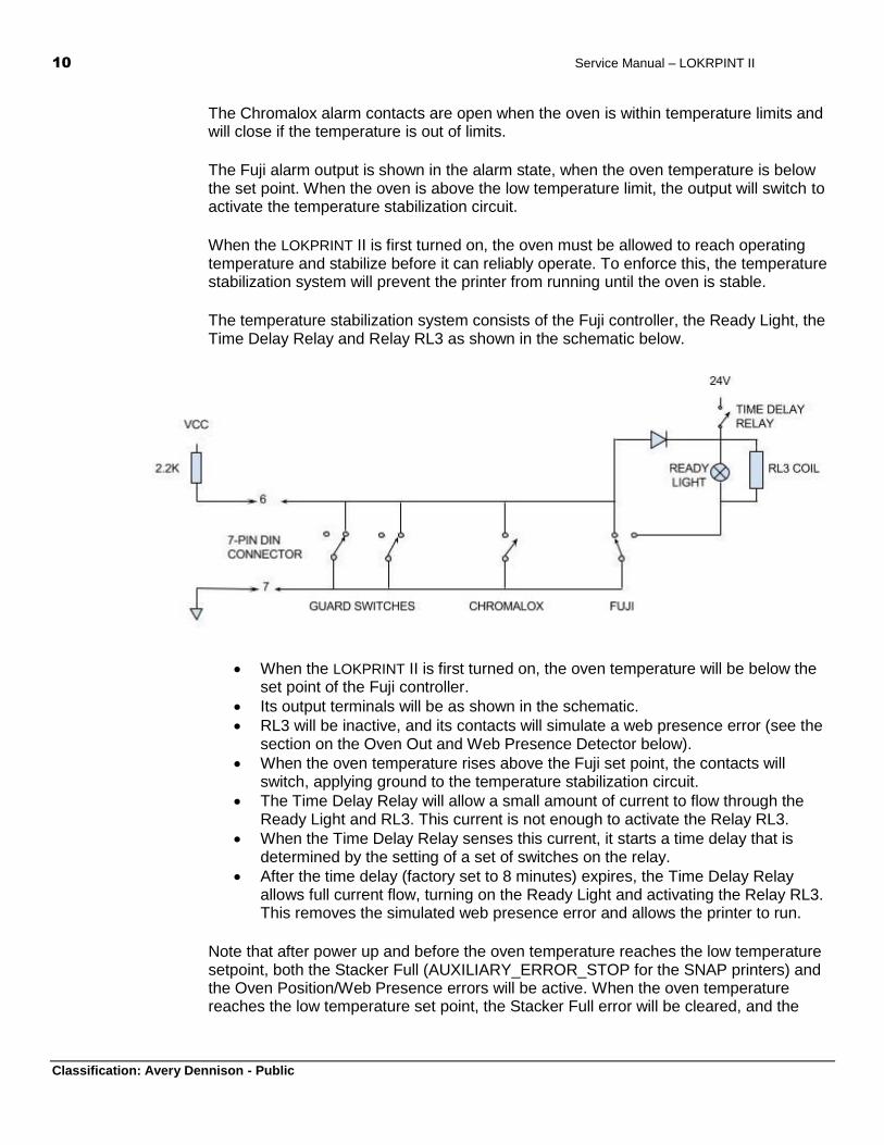
The circuit shown below implements the oven cover guards, temperature stabilization, and temperature alarms. When operating normally, all the switches are open, so the signal to the printer is pulled up to Vcc. This signal is connected to the Stacker Full signal on the 676 and to the AUXILIARY_ERROR_STOP signal on the AMB for the SNAP700.
The guard switches are connected as normally closed, so that when the cover is closed, the switches are open.
10 Service Manual – LOKRPINT II
Classification: Avery Dennison - Public
The Chromalox alarm contacts are open when the oven is within temperature limits and will close if the temperature is out of limits.
The Fuji alarm output is shown in the alarm state, when the oven temperature is below the set point. When the oven is above the low temperature limit, the output will switch to activate the temperature stabilization circuit.
When the LOKPRINT II is first turned on, the oven must be allowed to reach operating temperature and stabilize before it can reliably operate. To enforce this, the temperature stabilization system will prevent the printer from running until the oven is stable.
The temperature stabilization system consists of the Fuji controller, the Ready Light, the Time Delay Relay and Relay RL3 as shown in the schematic below.
When the LOKPRINT II is first turned on, the oven temperature will be below the set point of the Fuji controller.
Its output terminals will be as shown in the schematic.
RL3 will be inactive, and its contacts will simulate a web presence error (see the section on the Oven Out and Web Presence Detector below).
When the oven temperature rises above the Fuji set point, the contacts will switch, applying ground to the temperature stabilization circuit.
The Time Delay Relay will allow a small amount of current to flow through the Ready Light and RL3. This current is not enough to activate the Relay RL3.
When the Time Delay Relay senses this current, it starts a time delay that is determined by the setting of a set of switches on the relay.
After the time delay (factory set to 8 minutes) expires, the Time Delay Relay allows full current flow, turning on the Ready Light and activating the Relay RL3. This removes the simulated web presence error and allows the printer to run.
Note that after power up and before the oven temperature reaches the low temperature setpoint, both the Stacker Full (AUXILIARY_ERROR_STOP for the SNAP printers) and the Oven Position/Web Presence errors will be active. When the oven temperature reaches the low temperature set point, the Stacker Full error will be cleared, and the
Service Manual - LOKPRINT II 11
Classification: Avery Dennison - Public
Oven Position/Web Presence error will be active until the 8 minute time delay is complete.
If the oven temperature falls below the low temperature limit set on the Fuji controller, the contacts will switch back, signaling the printer to stop, and resetting the time delay relay. When the temperature risea above the low temperature limit, the time delay relay will hold off the printer for another 8 minutes to ensure the oven is again stabilized.
Error conditions regarding the oven temperature and cover are communicated to the printer though the 7-pin micro DIN Plug, pins 6 and 7.
In the original design, the 7-pin DIN plug connected directly to the 676 printer TCB. For the 676, pin 7 is connected to ground and pin 6 is the Stacker Full signal. When pin 6 is connected to pin 7, the printer will stop and display the CHECK STACKER error.
With the SNAP printer, the 7-pin DIN plug is connected to a mating connector in the 05621120 Harness, SNAP/ LOKPRINT Interface. This in turn connects to the SNAP printer internal harness (05621113 Harness, SNAP Output for LOKPRINT), which connects the error signal to the 62110 Auxiliary Motor Board connector J8 pins 6 (error) and 7 (ground).
Web Presence and Oven Position Sensors
The Web Presence Sensor is a C-sensor that is located just before the feed drive. It detects if the web is present. The printer will not run if the web is not present, and the printer will stop if the sensor detects the web is not present while the printer is running (e.g. if the web breaks or tracks off).
The Oven Position sensor sets the forward operating point of the oven. It is a C-sensor located inside the LOKPRINT II case, behind the oven. An arm attached to the oven blocks the sensor when the oven is back. A hole in the arm unblocks the sensor when it moves forward to the operating position. The sensor can make adjustments to the operating position.
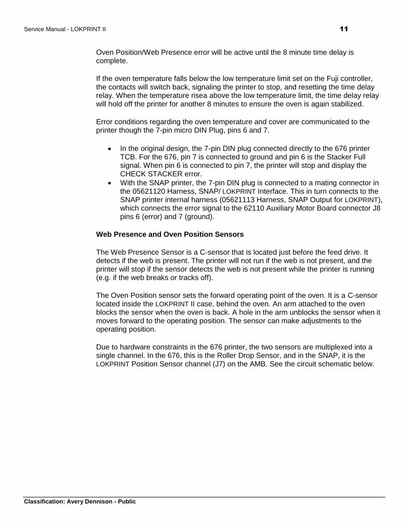
Due to hardware constraints in the 676 printer, the two sensors are multiplexed into a single channel. In the 676, this is the Roller Drop Sensor, and in the SNAP, it is the LOKPRINT Position Sensor channel (J7) on the AMB. See the circuit schematic below.
12 Service Manual – LOKRPINT II
Classification: Avery Dennison - Public
In addition to these sensors, the signal passes through the microswitch on the web tensioning device dancer (labeled DANCER in the schematic above) that is attached to the printer. This mechanism also detects the web presence with a dancer arm that is normally held in a horizontal position by the web. When it is in the horizontal position, a cam inactivates the microswitch, which is in series with the sensor signal. Since the NC contacts of the switch are used, that allows the sensor signal to pass through to the printer.
If the web loses tension, such as a web breakage, the switch activates, which blocks the signal from passing through to the printer. The printer will not run or will stop if running.
The sensor signal also passes through the contacts of RL3 in the LOKPRINT II. The sensor signal will be blocked from the printer if the Temperature Stability System is not active (see the description in the section Guard Switches, Temperature Stabilization, and Temperature Alarms above).
The sensor is read by an analog channel in the printer. The various combinations of web presence and oven out will result in unique voltages being passed through to the printer. See Appendix B for instructions for testing this circuit.
Feed
The LOKPRINT II feed motor (05221113) is powered through the 7-pin DIN plug. Pins 1 and 2 of the 7-pin DIN are connected directly to 24V from the printer and connect to one leg of the feed motor.
The other leg of the feed motor is connected through Rheostat (05561125) back to pins 2 and 3 of the 7 pin DIN connector. These in turn connect to a driver in the printer which switches those pins to ground when the printer is running. The Rheostat is adjusted so that the web remains taut but the feed roller does slip against the fabric
Service Manual - LOKPRINT II 13
Classification: Avery Dennison - Public
In addition, those pins of the 7-pin DIN connector also drive relay RL1, which connects 24V to the output 7-pin DIN connector on the output side of the LOKPRINT II. That is where the SS Finisher attaches.
24V Power Supply
Because the printer cannot supply enough 24V power to run the LOKPRINT II and the SS Finisher, a separate 24V supply is included in the LOKPRINT II. This power supply is on whenever the LOKPRINT II is on. It powers the Temperature Stabilization System, the ventilation fans, and the 7-pin DIN connector on the output side of the LOKPRINT II (see the Feed description, above).
How the Printer Detects When the LOKPRINT II is Connected
The printer automatically detects when the LOKPRINT II is connected. For the 676, this is controlled by the resistor and capacitor attached to pin 10 of the 15 pin D-shell connector (see the lower left of the LOKPRINT II schematic). This circuit is connected to a port on the TCB in the printer. A similar circuit with only a resistor to ground is connected to the same port in the LOKPRINT I.
During initialization, the 676 printer firmware drives this port line low. This causes the capacitor to discharge through the resistor. The printer then removes the low signal, and the capacitor starts to charge through a pull-up resistor on the TCB and the resistor in the LOKPRINT II. After a period of time, the printer reads the port line. In the LOKPRINT I, the resistor holds the line low, while on the LOKPRINT II, the capacitor charges to a higher voltage. If neither a LOKPRINT I nor LOKPRINT II is attached, the port’s internal pull-up brings the port line to 5V. The printer firmware uses the voltage reading on the port to determine what is attached.
For the SNAP printer, detecting what peripheral are attached is done using button memory devices in the interface cable. The firmware reads a special code from the device to determine what is attached. The resistor/capacitor circuit is not used.
14 Service Manual – LOKRPINT II
Classification: Avery Dennison - Public
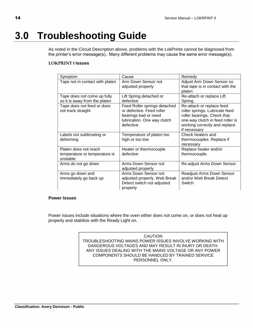
3.0 Troubleshooting Guide
As noted in the Circuit Description above, problems with the LokPrints cannot be diagnosed from the printer’s error message(s).. Many different problems may cause the same error message(s).
LOKPRINT I Issues
Power Issues
Power issues include situations where the oven either does not come on, or does not heat up properly and stabilize with the Ready Light on.
Symptom Cause Remedy
Tape not in contact with platen Arm Down Sensor not adjusted properly
Adjust Arm Down Sensor so that tape is in contact with the platen
Tape does not come up fully so it is away from the platen
Lift Spring detached or defective
Re-attach or replace Lift Spring
Tape does not feed or does not track straight
Feed Roller springs detached or defective. Feed roller bearings bad or need lubrication. One way clutch defective
Re-attach or replace feed roller springs. Lubricate feed roller bearings. Check that one-way clutch in feed roller is working correctly and replace if necessary
Labels not sublimating or deforming
Temperature of platen too high or too low
Check heaters and thermocouples. Replace if necessary
Platen does not reach temperature or temperature is unstable
Heater or thermocouple defective
Replace heater and/or thermocouple.
Arms do not go down Arms Down Sensor not adjusted properly
Re-adjust Arms Down Sensor
Arms go down and immediately go back up
Arms Down Sensor not adjusted properly. Web Break Detect switch not adjusted properly
Readjust Arms Down Sensor and/or Web Break Detect Switch
CAUTION TROUBLESHOOTING MAINS POWER ISSUES INVOLVE WORKING WITH
DANGEROUS VOLTAGES AND MAY RESULT IN INURY OR DEATH. ANY ISSUES DEALING WITH THE MAINS VOLTAGE OR ANY POWER
COMPONENTS SHOULD BE HANDLED BY TRAINED SERVICE PERSONNEL ONLY.
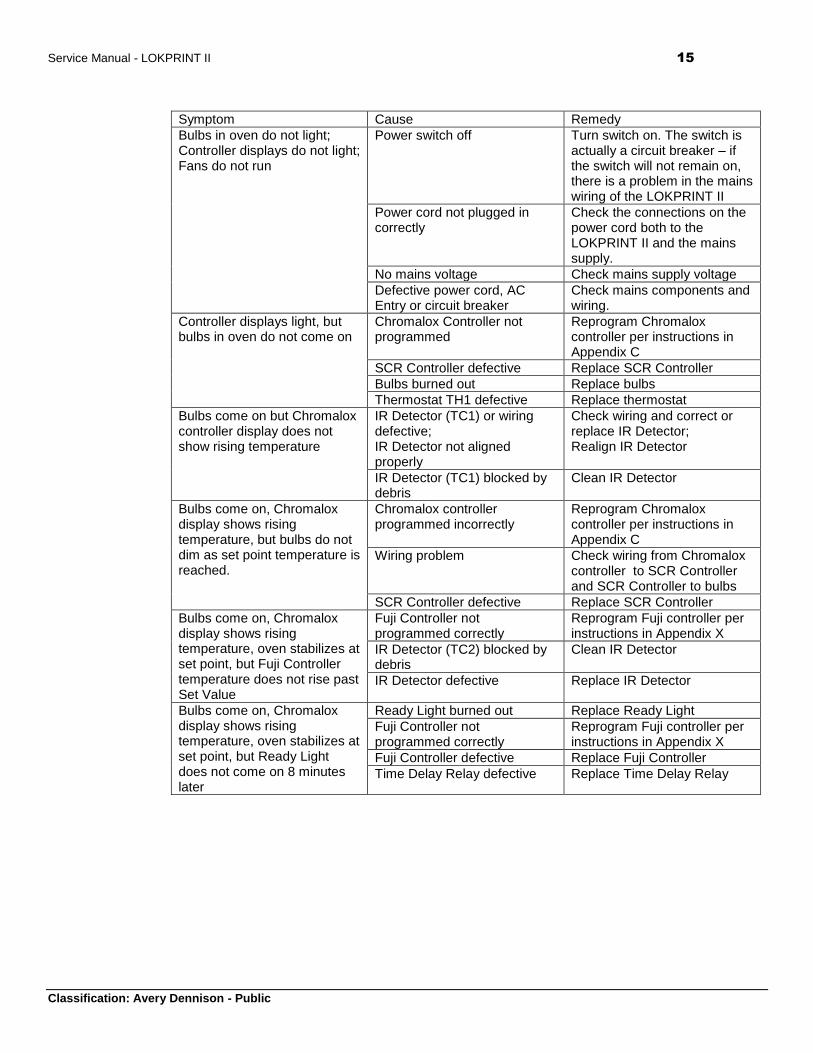
Service Manual - LOKPRINT II 15
Classification: Avery Dennison - Public
Symptom Cause Remedy
Bulbs in oven do not light; Controller displays do not light; Fans do not run
Power switch off Turn switch on. The switch is actually a circuit breaker – if the switch will not remain on, there is a problem in the mains wiring of the LOKPRINT II
Power cord not plugged in correctly
Check the connections on the power cord both to the LOKPRINT II and the mains supply.
No mains voltage Check mains supply voltage
Defective power cord, AC Entry or circuit breaker
Check mains components and wiring.
Controller displays light, but bulbs in oven do not come on
Chromalox Controller not programmed
Reprogram Chromalox controller per instructions in Appendix C
SCR Controller defective Replace SCR Controller
Bulbs burned out Replace bulbs
Thermostat TH1 defective Replace thermostat
Bulbs come on but Chromalox controller display does not show rising temperature
IR Detector (TC1) or wiring defective; IR Detector not aligned properly
Check wiring and correct or replace IR Detector; Realign IR Detector
IR Detector (TC1) blocked by debris
Clean IR Detector
Bulbs come on, Chromalox display shows rising temperature, but bulbs do not dim as set point temperature is reached.
Chromalox controller programmed incorrectly
Reprogram Chromalox controller per instructions in Appendix C
Wiring problem Check wiring from Chromalox controller to SCR Controller and SCR Controller to bulbs
SCR Controller defective Replace SCR Controller
Bulbs come on, Chromalox display shows rising temperature, oven stabilizes at set point, but Fuji Controller temperature does not rise past Set Value
Fuji Controller not programmed correctly
Reprogram Fuji controller per instructions in Appendix X
IR Detector (TC2) blocked by debris
Clean IR Detector
IR Detector defective Replace IR Detector
Bulbs come on, Chromalox display shows rising temperature, oven stabilizes at set point, but Ready Light does not come on 8 minutes later
Ready Light burned out Replace Ready Light
Fuji Controller not programmed correctly
Reprogram Fuji controller per instructions in Appendix X
Fuji Controller defective Replace Fuji Controller
Time Delay Relay defective Replace Time Delay Relay
16 Service Manual – LOKRPINT II
Classification: Avery Dennison - Public
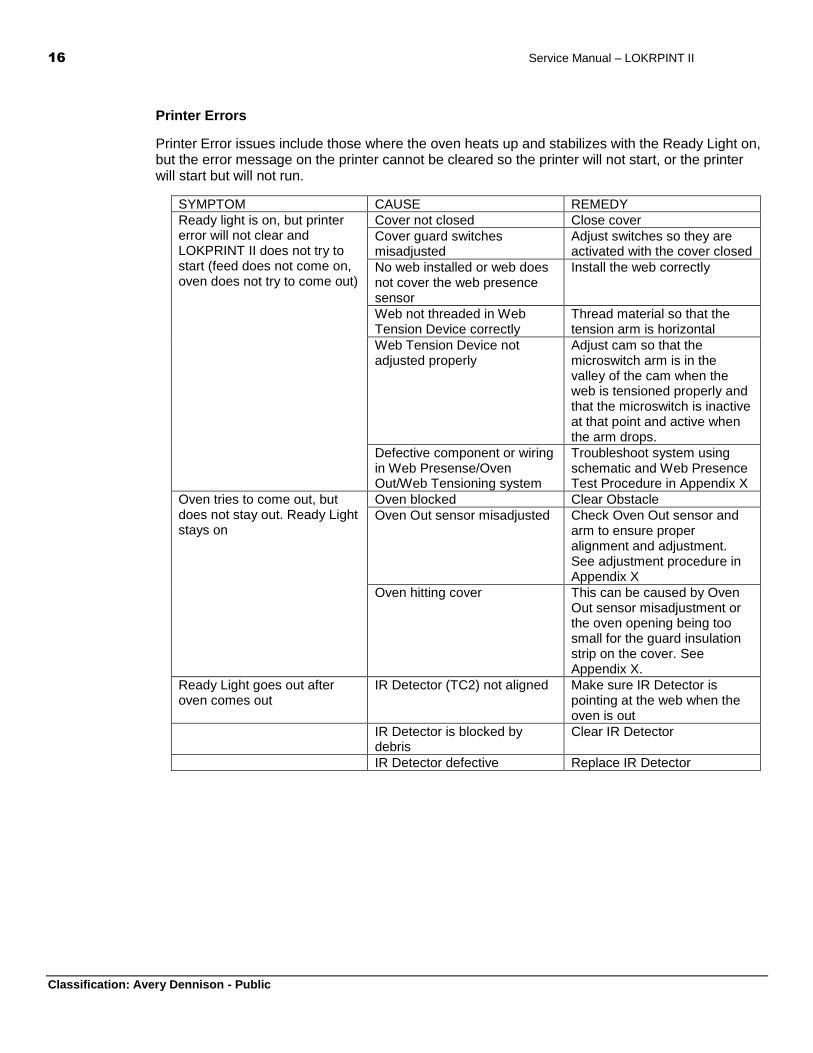
Printer Errors
Printer Error issues include those where the oven heats up and stabilizes with the Ready Light on, but the error message on the printer cannot be cleared so the printer will not start, or the printer will start but will not run.
SYMPTOM CAUSE REMEDY
Ready light is on, but printer error will not clear and LOKPRINT II does not try to start (feed does not come on, oven does not try to come out)
Cover not closed Close cover
Cover guard switches misadjusted
Adjust switches so they are activated with the cover closed
No web installed or web does not cover the web presence sensor
Install the web correctly
Web not threaded in Web Tension Device correctly
Thread material so that the tension arm is horizontal
Web Tension Device not adjusted properly
Adjust cam so that the microswitch arm is in the valley of the cam when the web is tensioned properly and that the microswitch is inactive at that point and active when the arm drops.
Defective component or wiring in Web Presense/Oven Out/Web Tensioning system
Troubleshoot system using schematic and Web Presence Test Procedure in Appendix X
Oven tries to come out, but does not stay out. Ready Light stays on
Oven blocked Clear Obstacle
Oven Out sensor misadjusted Check Oven Out sensor and arm to ensure proper alignment and adjustment. See adjustment procedure in Appendix X
Oven hitting cover This can be caused by Oven Out sensor misadjustment or the oven opening being too small for the guard insulation strip on the cover. See Appendix X.
Ready Light goes out after oven comes out
IR Detector (TC2) not aligned Make sure IR Detector is pointing at the web when the oven is out
IR Detector is blocked by debris
Clear IR Detector
IR Detector defective Replace IR Detector
Service Manual - LOKPRINT II 17
Classification: Avery Dennison - Public
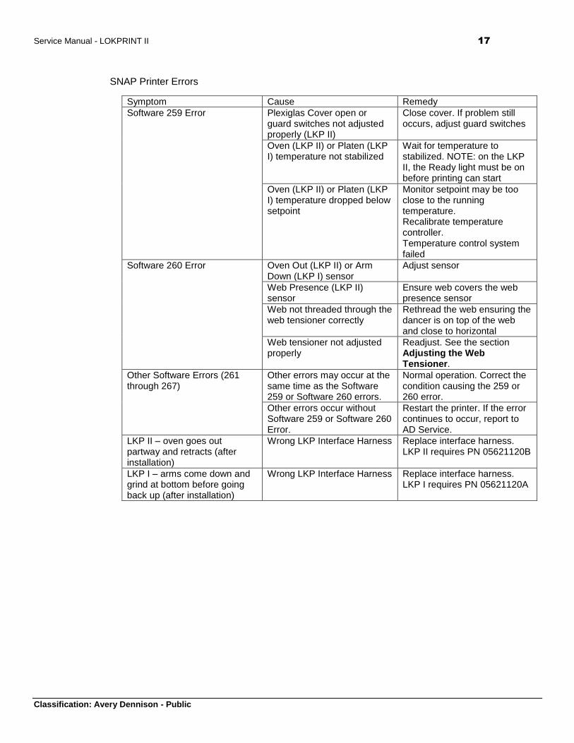
SNAP Printer Errors
Symptom Cause Remedy
Software 259 Error Plexiglas Cover open or guard switches not adjusted properly (LKP II)
Close cover. If problem still occurs, adjust guard switches
Oven (LKP II) or Platen (LKP I) temperature not stabilized
Wait for temperature to stabilized. NOTE: on the LKP II, the Ready light must be on before printing can start
Oven (LKP II) or Platen (LKP I) temperature dropped below setpoint
Monitor setpoint may be too close to the running temperature. Recalibrate temperature controller. Temperature control system failed
Software 260 Error Oven Out (LKP II) or Arm Down (LKP I) sensor
Adjust sensor
Web Presence (LKP II) sensor
Ensure web covers the web presence sensor
Web not threaded through the web tensioner correctly
Rethread the web ensuring the dancer is on top of the web and close to horizontal
Web tensioner not adjusted properly
Readjust. See the section Adjusting the Web Tensioner.
Other Software Errors (261 through 267)
Other errors may occur at the same time as the Software 259 or Software 260 errors.
Normal operation. Correct the condition causing the 259 or 260 error.
Other errors occur without Software 259 or Software 260 Error.
Restart the printer. If the error continues to occur, report to AD Service.
LKP II – oven goes out partway and retracts (after installation)
Wrong LKP Interface Harness Replace interface harness. LKP II requires PN 05621120B
LKP I – arms come down and grind at bottom before going back up (after installation)
Wrong LKP Interface Harness Replace interface harness. LKP I requires PN 05621120A
18 Service Manual – LOKRPINT II
Classification: Avery Dennison - Public
4.0 Web Presence / Oven Out Sensor
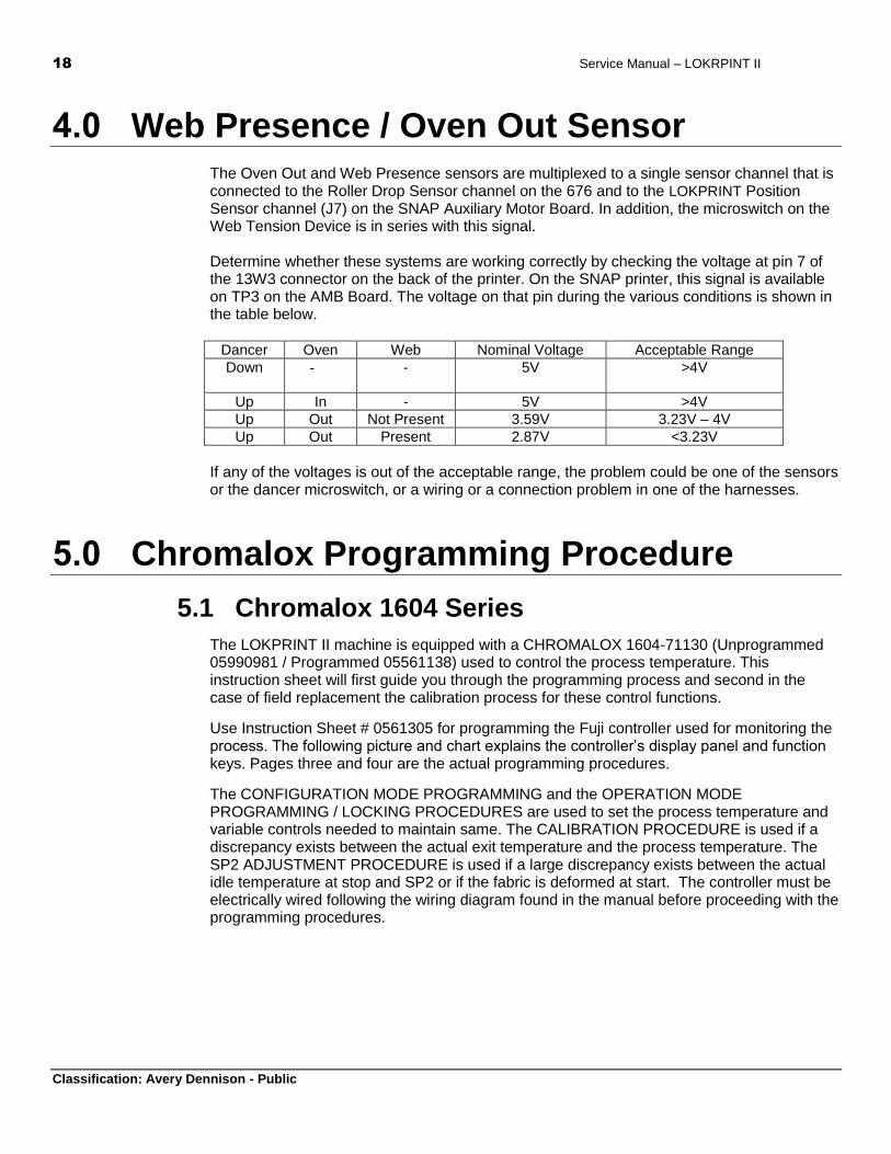
The Oven Out and Web Presence sensors are multiplexed to a single sensor channel that is connected to the Roller Drop Sensor channel on the 676 and to the LOKPRINT Position Sensor channel (J7) on the SNAP Auxiliary Motor Board. In addition, the microswitch on the Web Tension Device is in series with this signal. Determine whether these systems are working correctly by checking the voltage at pin 7 of the 13W3 connector on the back of the printer. On the SNAP printer, this signal is available on TP3 on the AMB Board. The voltage on that pin during the various conditions is shown in the table below.
Dancer Oven Web Nominal Voltage Acceptable Range
Down - - 5V >4V
Up In - 5V >4V
Up Out Not Present 3.59V 3.23V – 4V
Up Out Present 2.87V <3.23V
If any of the voltages is out of the acceptable range, the problem could be one of the sensors or the dancer microswitch, or a wiring or a connection problem in one of the harnesses.
5.0 Chromalox Programming Procedure
5.1 Chromalox 1604 Series
The LOKPRINT II machine is equipped with a CHROMALOX 1604-71130 (Unprogrammed 05990981 / Programmed 05561138) used to control the process temperature. This instruction sheet will first guide you through the programming process and second in the case of field replacement the calibration process for these control functions.
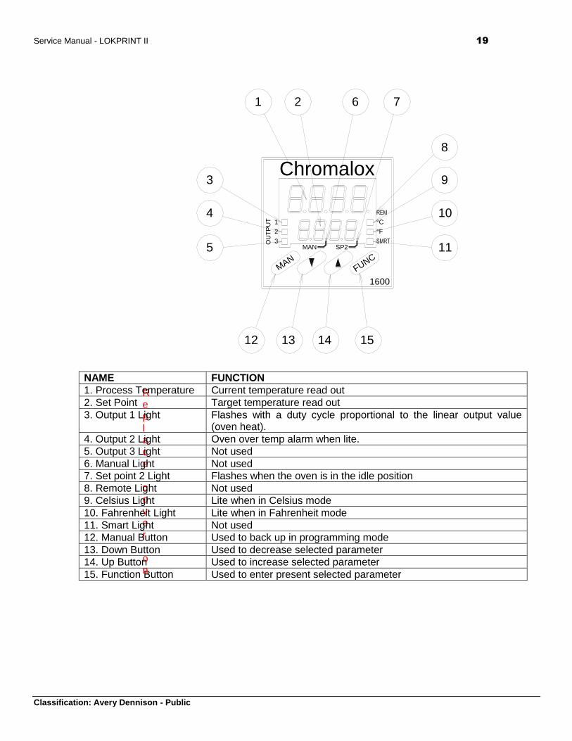
Use Instruction Sheet # 0561305 for programming the Fuji controller used for monitoring the process. The following picture and chart explains the controller’s display panel and function keys. Pages three and four are the actual programming procedures.
The CONFIGURATION MODE PROGRAMMING and the OPERATION MODE PROGRAMMING / LOCKING PROCEDURES are used to set the process temperature and variable controls needed to maintain same. The CALIBRATION PROCEDURE is used if a discrepancy exists between the actual exit temperature and the process temperature. The SP2 ADJUSTMENT PROCEDURE is used if a large discrepancy exists between the actual idle temperature at stop and SP2 or if the fabric is deformed at start. The controller must be electrically wired following the wiring diagram found in the manual before proceeding with the programming procedures.
Service Manual - LOKPRINT II 19
Classification: Avery Dennison - Public
Chromalox
1600
OU
TP
UT 1
2
3
°F
°C
MANFUNC
MAN SP2
1 2
3
4
5
12 13 14 15
9
11
10
8
6 7
Replace cover on
NAME FUNCTION
1. Process Temperature Current temperature read out
2. Set Point Target temperature read out
3. Output 1 Light Flashes with a duty cycle proportional to the linear output value (oven heat).
4. Output 2 Light Oven over temp alarm when lite.
5. Output 3 Light Not used
6. Manual Light Not used
7. Set point 2 Light Flashes when the oven is in the idle position
8. Remote Light Not used
9. Celsius Light Lite when in Celsius mode
10. Fahrenheit Light Lite when in Fahrenheit mode
11. Smart Light Not used
12. Manual Button Used to back up in programming mode
13. Down Button Used to decrease selected parameter
14. Up Button Used to increase selected parameter
15. Function Button Used to enter present selected parameter
20 Service Manual – LOKRPINT II
Classification: Avery Dennison - Public
CONFIGURATION MODE PROGRAMMING PROCEDURE: Use this procedure in conjunction with the OPERATION MODE PROGRAMING / LOCKING PROCEDURE to set the process temperature and variable controls needed to maintain same.
1. Depress the concealed configuration switch with a small ball driver and power the machine on to display COnF.
2. Press the FUNC button to display X SEr1.
3. Press the UP / DOWN button(s) until OFF SEr1 is displayed.
4. Press the FUNC button to display X P1.
5. Press the UP / DOWN button(s) until 21 P1 is displayed.
6. Press the FUNC button to display X P3.
7. Press the UP / DOWN button(s) until 0 P3 is displayed.
8. Press the FUNC button to display X P4.
9. Press the UP / DOWN button(s) until 1830 P4 is displayed (holding the UP or DOWN button down will cause the next significant digit to increment or decrement after each 10 count).
10. Press the FUNC button to display X P5.
11. Press the UP / DOWN button(s) until rEU P5 is displayed.
12. Press the FUNC button to display X P6.
13. Press the UP / DOWN button(s) until 4-20 P6 is displayed.
14. Press the FUNC button to display X P9.
15. Press the UP / DOWN button(s) until AL1.P P9 is displayed.
16. Press the FUNC button to display X P10.
17. Press the UP / DOWN button(s) until H.A. P10 is displayed.
18. Press the FUNC button to display X P11.
19. Press the UP / DOWN button(s) until nonE P11 is displayed.
20. Press the FUNC button to display X P16.
21. Press the UP / DOWN button(s) until 0 P16 is displayed.
22. Press the FUNC button to display X P17.
23. Press the UP / DOWN button(s) until 0 P17 is displayed.
24. Press the FUNC button to display -.-.-.-. -.-.-.-..
25. Press the UP / DOWN button(s) until 262 -.-.-.-. is displayed.
26. Press the FUNC button to display X P18.
27. Press the UP / DOWN button(s) until norL P18 is displayed.
Service Manual - LOKPRINT II 21
Classification: Avery Dennison - Public
28. Press the FUNC button to display X P19.
29. Press the UP / DOWN button(s) until norL P19 is displayed.
30. Press the FUNC button to display X P24.
31. Press the UP / DOWN button(s) until dir P24 is displayed.
32. Press the FUNC button to display X P25.
33. Press the UP / DOWN button(s) until OFF P25 is displayed.
34. Press the FUNC button to display X P28.
35. Press the FUNC button to display X P30.
36. Press the UP / DOWN button(s) until 0 P30 is displayed.
37. Press the FUNC button to display X P34.
38. Press the Up / Down button(s) until OFF P34 is displayed.
39. Press the FUNC button to display X P36.
40. Press the UP / DOWN button(s) until En.30 P36 is displayed.
41. Press the FUNC button to display X P37.
42. Press the UP / DOWN button(s) until 0 P37 is displayed.
43. Press the FUNC button to display X P39.
44. Press the UP / DOWN button(s) until nOFL P39 is displayed.
45. Press the FUNC button to display X P41.
46. Press the UP / DOWN button(s) until P.I.d. P41 is displayed.
47. Press the FUNC button to display X P42.
48. Press the UP / DOWN button(s) until 10.0 P42 is displayed.
49. Press the FUNC button to display X P43.
50. Press the UP / DOWN button(s) until Fn.SP P43 is displayed.
51. Press the FUNC button to display X P44.
52. Press the UP / DOWN button(s) until 0 P44 is displayed.
53. Press the FUNC button to display COnF.
54. Power the machine off and depress the concealed configuration switch with a small ball driver.
55. End of procedure, proceed directly to OPERATION MODE PROGRAMMING / LOCKING PROCEDURE.
22 Service Manual – LOKRPINT II
Classification: Avery Dennison - Public
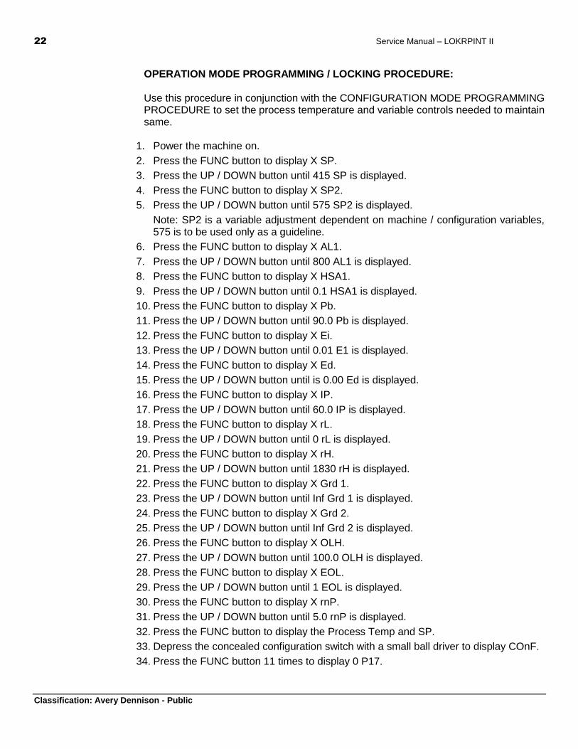
OPERATION MODE PROGRAMMING / LOCKING PROCEDURE: Use this procedure in conjunction with the CONFIGURATION MODE PROGRAMMING PROCEDURE to set the process temperature and variable controls needed to maintain same.
1. Power the machine on.
2. Press the FUNC button to display X SP.
3. Press the UP / DOWN button until 415 SP is displayed.
4. Press the FUNC button to display X SP2.
5. Press the UP / DOWN button until 575 SP2 is displayed.
Note: SP2 is a variable adjustment dependent on machine / configuration variables, 575 is to be used only as a guideline.
6. Press the FUNC button to display X AL1.
7. Press the UP / DOWN button until 800 AL1 is displayed.
8. Press the FUNC button to display X HSA1.
9. Press the UP / DOWN button until 0.1 HSA1 is displayed.
10. Press the FUNC button to display X Pb.
11. Press the UP / DOWN button until 90.0 Pb is displayed.
12. Press the FUNC button to display X Ei.
13. Press the UP / DOWN button until 0.01 E1 is displayed.
14. Press the FUNC button to display X Ed.
15. Press the UP / DOWN button until is 0.00 Ed is displayed.
16. Press the FUNC button to display X IP.
17. Press the UP / DOWN button until 60.0 IP is displayed.
18. Press the FUNC button to display X rL.
19. Press the UP / DOWN button until 0 rL is displayed.
20. Press the FUNC button to display X rH.
21. Press the UP / DOWN button until 1830 rH is displayed.
22. Press the FUNC button to display X Grd 1.
23. Press the UP / DOWN button until Inf Grd 1 is displayed.
24. Press the FUNC button to display X Grd 2.
25. Press the UP / DOWN button until Inf Grd 2 is displayed.
26. Press the FUNC button to display X OLH.
27. Press the UP / DOWN button until 100.0 OLH is displayed.
28. Press the FUNC button to display X EOL.
29. Press the UP / DOWN button until 1 EOL is displayed.
30. Press the FUNC button to display X rnP.
31. Press the UP / DOWN button until 5.0 rnP is displayed.
32. Press the FUNC button to display the Process Temp and SP.
33. Depress the concealed configuration switch with a small ball driver to display COnF.
34. Press the FUNC button 11 times to display 0 P17.

Service Manual - LOKPRINT II 23
Classification: Avery Dennison - Public
35. Press the UP button to display 1 P17.
36. Press the FUNC button to display -.-.-.-. -.-.-.-.
37. Depress the concealed configuration switch with a small ball driver.
38. In the case of a first time programming create and apply a label to the controller with the “PN 561138” printed on it.
39. End of procedure.
Once both the Configuration and Operation Mode Programming / Locking Procedures are complete the machine should be powered on long enough to allow it to stabilize at the idle temperature (SP2).
Run the machine long enough to stabilize at SP, measure and record the exit temperature of the web just before the feed rollers with a hand held non contact thermal measuring device. It is possible that the exit temperature is off enough to cause the monitor (Fuji) or the controller (Chromalox) to shut down the system because of an under or over temperature condition. If so proceed directly to the Calibration Procedure.
If the actual exit temperature equals the target exit temperature of 400 degrees Fahrenheit stop the machine and allow it to re-stabilize at SP2.
Restart the machine and confirm that an under temperature (with or without the Fuji stopping the printer) or over temperature (fabric is deformed / melted) condition does not exist. If either condition exists process to the SP2 ADJUSTMENT PROCEDURE.
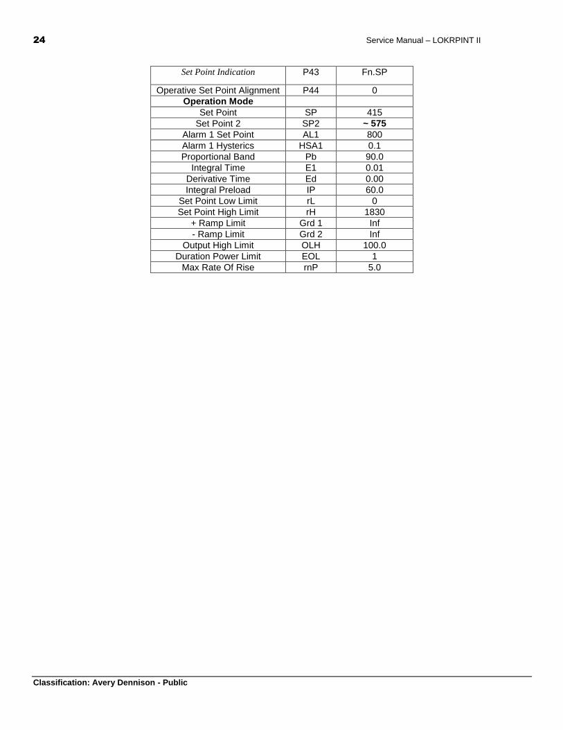
PROCESS CONTROL PROGRAMMING CHART
Perimeter Symbol Setting
Configuration Mode
Serial Interface Protocol Ser1 OFF
Input Type P1 21
Initial Scale Value P3 0
Full Scale Value P4 1830
Output 1 Function P5 rEU
Output 1 Type P6 4 – 20
Output 2 Function P9 AL1.P
Alarm 1 Operating Mode P10 H.A.
Output 3 Function P11 nonE
Threshold of Soft Start P16 0
Security Code P17 1 (after programming)
Output 1 Control Action P18 norL
Output 1 Control Display P19 norL
Alarm 1 Action P24 dir
Alarm 1 Inhibit Function P25 OFF
Offset P28 X
Smart Function P30 0
Manual Function P34 OFF
Timeout Selection P36 En.30
Output Safety Value P37 0
Digital Filter P39 nOFL
Control Action Type P41 P.I.d.
Anti-Reset-Wind-Up P42 10.0
24 Service Manual – LOKRPINT II
Classification: Avery Dennison - Public
Set Point Indication P43 Fn.SP
Operative Set Point Alignment P44 0
Operation Mode
Set Point SP 415
Set Point 2 SP2 ~ 575
Alarm 1 Set Point AL1 800
Alarm 1 Hysterics HSA1 0.1
Proportional Band Pb 90.0
Integral Time E1 0.01
Derivative Time Ed 0.00
Integral Preload IP 60.0
Set Point Low Limit rL 0
Set Point High Limit rH 1830
+ Ramp Limit Grd 1 Inf
- Ramp Limit Grd 2 Inf
Output High Limit OLH 100.0
Duration Power Limit EOL 1
Max Rate Of Rise rnP 5.0
Service Manual - LOKPRINT II 25
Classification: Avery Dennison - Public
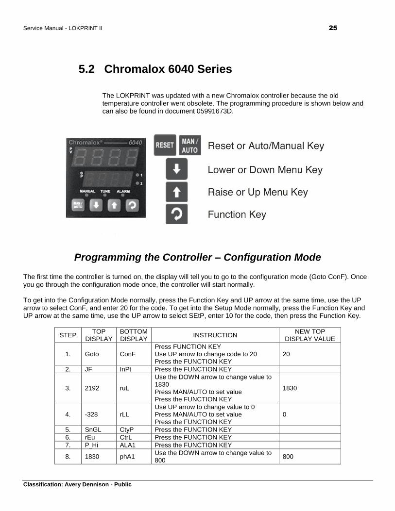
5.2 Chromalox 6040 Series
The LOKPRINT was updated with a new Chromalox controller because the old temperature controller went obsolete. The programming procedure is shown below and can also be found in document 05991673D.
Programming the Controller – Configuration Mode The first time the controller is turned on, the display will tell you to go to the configuration mode (Goto ConF). Once you go through the configuration mode once, the controller will start normally. To get into the Configuration Mode normally, press the Function Key and UP arrow at the same time, use the UP arrow to select ConF, and enter 20 for the code. To get into the Setup Mode normally, press the Function Key and UP arrow at the same time, use the UP arrow to select SEtP, enter 10 for the code, then press the Function Key.
STEP TOP
DISPLAY BOTTOM DISPLAY
INSTRUCTION NEW TOP
DISPLAY VALUE
1. Goto ConF Press FUNCTION KEY Use UP arrow to change code to 20 Press the FUNCTION KEY
20
2. JF InPt Press the FUNCTION KEY
3. 2192 ruL
Use the DOWN arrow to change value to 1830 Press MAN/AUTO to set value Press the FUNCTION KEY
1830
4. -328 rLL Use UP arrow to change value to 0 Press MAN/AUTO to set value Press the FUNCTION KEY
0
5. SnGL CtyP Press the FUNCTION KEY
6. rEu CtrL Press the FUNCTION KEY
7. P_Hi ALA1 Press the FUNCTION KEY
8. 1830 phA1 Use the DOWN arrow to change value to 800
800
26 Service Manual – LOKRPINT II
Classification: Avery Dennison - Public
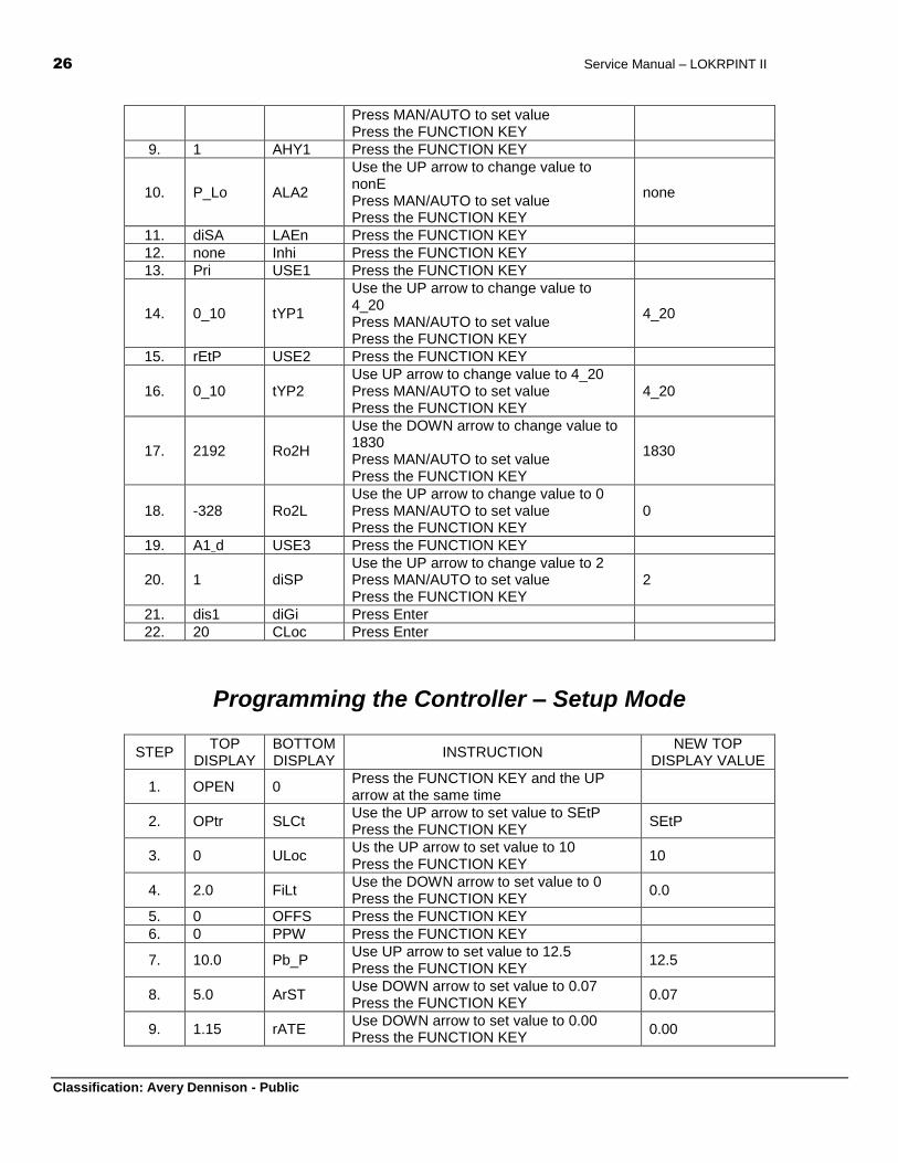
Press MAN/AUTO to set value Press the FUNCTION KEY
9. 1 AHY1 Press the FUNCTION KEY
10. P_Lo ALA2
Use the UP arrow to change value to nonE Press MAN/AUTO to set value Press the FUNCTION KEY
none
11. diSA LAEn Press the FUNCTION KEY
12. none Inhi Press the FUNCTION KEY
13. Pri USE1 Press the FUNCTION KEY
14. 0_10 tYP1
Use the UP arrow to change value to 4_20 Press MAN/AUTO to set value Press the FUNCTION KEY
4_20
15. rEtP USE2 Press the FUNCTION KEY
16. 0_10 tYP2 Use UP arrow to change value to 4_20 Press MAN/AUTO to set value Press the FUNCTION KEY
4_20
17. 2192 Ro2H
Use the DOWN arrow to change value to 1830 Press MAN/AUTO to set value Press the FUNCTION KEY
1830
18. -328 Ro2L Use the UP arrow to change value to 0 Press MAN/AUTO to set value Press the FUNCTION KEY
0
19. A1_d USE3 Press the FUNCTION KEY
20. 1 diSP Use the UP arrow to change value to 2 Press MAN/AUTO to set value Press the FUNCTION KEY
2
21. dis1 diGi Press Enter
22. 20 CLoc Press Enter
Programming the Controller – Setup Mode
STEP TOP
DISPLAY BOTTOM DISPLAY
INSTRUCTION NEW TOP
DISPLAY VALUE
1. OPEN 0 Press the FUNCTION KEY and the UP arrow at the same time
2. OPtr SLCt Use the UP arrow to set value to SEtP Press the FUNCTION KEY
SEtP
3. 0 ULoc Us the UP arrow to set value to 10 Press the FUNCTION KEY
10
4. 2.0 FiLt Use the DOWN arrow to set value to 0 Press the FUNCTION KEY
0.0
5. 0 OFFS Press the FUNCTION KEY
6. 0 PPW Press the FUNCTION KEY
7. 10.0 Pb_P Use UP arrow to set value to 12.5 Press the FUNCTION KEY
12.5
8. 5.0 ArST Use DOWN arrow to set value to 0.07 Press the FUNCTION KEY
0.07
9. 1.15 rATE Use DOWN arrow to set value to 0.00 Press the FUNCTION KEY
0.00
Service Manual - LOKPRINT II 27
Classification: Avery Dennison - Public
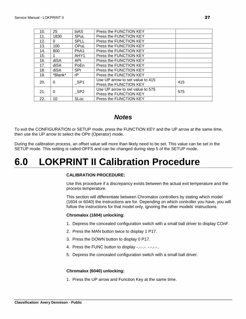
10. 25 biAS Press the FUNCTION KEY
11. 1830 SPuL Press the FUNCTION KEY
12. 0 SPLL Press the FUNCTION KEY
13. 100 OPuL Press the FUNCTION KEY
14. 800 PhA1 Press the FUNCTION KEY
15. 1 AHY1 Press the FUNCTION KEY
16. diSA APt Press the FUNCTION KEY
17. diSA PoEn Press the FUNCTION KEY
18. diSA SPr Press the FUNCTION KEY
19. *Blank* rP Press the FUNCTION KEY
20. 0 _SP1 Use UP arrow to set value to 415 Press the FUNCTION KEY
415
21. 0 _SP2 Use UP arrow to set value to 575 Press the FUNCTION KEY
575
22. 10 SLoc Press the FUNCTION KEY
Notes To exit the CONFIGURATION or SETUP mode, press the FUNCTION KEY and the UP arrow at the same time, then use the UP arrow to select the OPtr (Operator) mode.
During the calibration process, an offset value will more than likely need to be set. This value can be set in the SETUP mode. This setting is called OFFS and can be changed during step 5 of the SETUP mode.
6.0 LOKPRINT II Calibration Procedure
CALIBRATION PROCEDURE:
Use this procedure if a discrepancy exists between the actual exit temperature and the process temperature.
This section will differentiate between Chromalox controllers by stating which model (1604 or 6040) the instructions are for. Depending on which controller you have, you will follow the instructions for that model only, ignoring the other models’ instructions.
Chromalox (1604) unlocking:
1. Depress the concealed configuration switch with a small ball driver to display COnF.
2. Press the MAN button twice to display 1 P17.
3. Press the DOWN button to display 0 P17.
4. Press the FUNC button to display -.-.-.-. -.-.-.-..
5. Depress the concealed configuration switch with a small ball driver.
Chromalox (6040) unlocking:
1. Press the UP arrow and Function Key at the same time.
28 Service Manual – LOKRPINT II
Classification: Avery Dennison - Public
2. Press the UP arrow to select CONF or SEtP mode, depending on which setting you’d like to change. See the tables in section 5.1 to find which settings are where.
3. Press the Function Key.
4. Use the UP arrow to enter 10 for the Setup menu or 20 for the Configuration menu.
5. Press the Function Key.
Chromalox (1604) raising over temperature alarm:
1. Press the FUNC button three times to display 800 AL1.
2. Press the UP / DOWN button until 1000 AL1 is displayed.
3. Press the FUNC button to display 0.1 HSA1.
Chromalox (6040) raising over temperature alarm:
1. Press the UP arrow and Function Key at the same time.
2. Press the UP arrow to select CONF mode, press the Function Key.
3. Use the UP arrow to enter 20, press the Function Key.
4. Press the Function Key 6 times until phA1 is shown.
5. Change value to 1000, press MAN/AUTO to set value, press Function Key.
6. Press the UP arrow and Function Key at the same time to exit menu.
Fuji unlocking:
1. Press the SEL button nine times to display LoC.
2. Press the DATA button to display 1.
3. Press the ones UP button to cause the 1 to flash.
4. Press the DOWN button to display 000.
5. Press the ENTER button to display LoC.
Fuji turning digital filtering off:
1. Press and hold the SEL button to display P-n1.
2. Press the SEL button twice to display P-dF.
3. Press the DATA button to display 5.0.
4. Press the tens UP button to cause the 5 to flash.
5. Press the DOWN button five times to display 00.0.
Service Manual - LOKPRINT II 29
Classification: Avery Dennison - Public
6. Press the ENTER button to display P-SL.
Fuji lowering the under temperature alarm:
1. Press the PV/SV button to light the SV LED.
2. Press the one hundreds UP button to cause the 4 to flash.
3. Press the DOWN button four times to display 000.
4. Press the ENTER button to display 00.
Chromalox (1604) calibration:
1. Allow the machine to stabilize at the idle temperature (SP2). Run the machine until it stabilizes at SP (415), measure and record the exit temperature. If the actual exit temperature is lower than 400 your will need to make the Chromalox P28 a more negative number, if the actual exit temperature is higher than 400 make P28 a more positive number.
2. Depress the concealed configuration switch with a small ball driver to display COnF.
3. Press the MAN button to display -.-.-.-. -.-.-.-..
4. Press the UP / DOWN button until 262 -.-.-.-. is displayed.
5. Press the FUNC button to display norL P18.
6. Press the FUNC button four times to display X P28.
7. Adjust P28 as needed by pressing the UP / DOWN button followed by the FUNC button to enter the new offset (refer to step 24).
8. Depress the concealed configuration switch with a small ball driver and allow it to stabilize at the idle temperature (SP2). Run the machine until it stabilizes at SP (415), measure and record the exit temperature.
9. Repeat steps 25 – 30 until the stabilized exit temperature equals 400.
Chromalox (6040) calibration:
1. Allow the machine to stabilize at the idle temperature (SP2). Run the machine until it stabilizes at SP (415), measure and record the exit temperature. If the actual exit temperature is lower than 400 your will need to make the Chromalox OFFS a more negative number, if the actual exit temperature is higher than 400 make OFFS a more positive number.
2. Press the UP arrow and Function Key at the same time.
3. Press the UP arrow to select SEtP mode.
4. Press the Function Key.
5. Use the UP arrow to enter 10, press the Function Key.
6. Press the Function Key once to get to the OFFS value.
30 Service Manual – LOKRPINT II
Classification: Avery Dennison - Public
7. Adjust OFFS as needed by pressing the UP / DOWN button followed by the FUNC button to enter the new offset value.
8. Press the Function Key and Up arrow at the same time to exit the menu and allow the LOKPRINT to stabilize at the idle temperature (SP2). Run the machine until it stabilizes at SP (415), measure and record the exit temperature.
9. Repeat steps 25 – 30 until the stabilized exit temperature equals 400.
Fuji recalibration:
1. While running stabilized at SP (415) confirm that the Fuji PV is 415, if not it must be recalibrated.
2. Press and hold the SEL button until P-n1 is displayed.
3. Press the SEL button six times to display PUOF.
4. Press the DATA button to display X. Change and enter X according to the offset needed to cause the PV to be 415 while running. Once the change has been entered press the PV/SV button twice to display the PV.
5. Repeat step 35 until the Fuji’s PV is 415 while running stabilized at 415.
Fuji resetting the under temperature alarm:
1. Press the PV/SV button to light the SV LED.
2. Press the UP / DOWN buttons until 400 is displayed.
3. Press the ENTER button to enter 400 as the set value.
Fuji turning digital filtering back on:
1. Press and hold the SEL button to display P-n1.
2. Press the SEL button twice to display P-dF.
3. Press the DATA button to display 0.0.
4. Press the tens UP button six times to display 05.0.
5. Press the ENTER button to display P-SL.
Fuji relocking:
1. Press and hold the SEL button to display P.
2. Press the SEL button eight times to display LoC.
3. Press the DATA button to display 0.
4. Press the ones UP button twice to display 001.
5. Press the ENTER button to display LoC.
Service Manual - LOKPRINT II 31
Classification: Avery Dennison - Public
Chromalox (1604) resetting over temperature alarm:
1. Press the FUNC button three times to display 1000 AL1.
2. Press the UP / DOWN buttons until 800 is displayed.
3. Press the FUNC button to display 0.1 HSA1.
Chromalox (6040) raising over temperature alarm:
1. Press the UP arrow and Function Key at the same time.
2. Press the UP arrow to select CONF mode, press the Function Key.
3. Use the UP arrow to enter 20, press the Function Key.
4. Press the Function Key 6 times until phA1 is shown.
5. Change value to 800, press MAN/AUTO to set value, press Function Key.
6. Press the UP arrow and Function Key at the same time to exit menu.
Chromalox (1604) relocking:
1. Depress the concealed configuration switch with a small ball driver to display COnF.
2. Press the MAN button twice to display 0 P17.
3. Press the UP button to display 1 P17.
4. Press the FUNC button to display -.-.-.-. -.-.-.-..
5. Depress the concealed configuration switch with a small ball driver.
6. End of procedure move to SP2 Adjustment Procedure.
SP2 ADJUSTMENT PROCEDURE:
Use this procedure if the process temperature dips (with or without an under temperature stop) or if an over temperature (fabric is deformed / melted) condition occurs at start up.
1. To determine if SP2 is too high or too low restart the machine after allowing it to stabilize at SP2 and take notice if the fabric at the oven exit is deformed or if the process temperature (top readout on the Chromalox) dips (with or without an under temperature stop) during the transition phase from SP2 to SP.
Changing SP2 (Chromalox 1604):
1. Press the FUNC button twice to display X SP2.
2. Press the UP / DOWN button until SP2 equals 5 degrees higher or lower than its present value based on the results of step 1 (step 6 in the case of a repeat adjustment).
3. Press the FUNC button to display X AL1.
32 Service Manual – LOKRPINT II
Classification: Avery Dennison - Public
4. Press the MAN button 3 times to return to the Process Temp / SP screen.
5. Again while stabilized at SP2 restart the machine and take notice if the fabric at the oven exit is deformed or if the process temperature dips (with or without an under temperature stop) during the transition phase from SP2 to SP.
6. If either condition exists in step 6 repeat steps 2 – 6, if not proceed to step 8.
7. End of procedure.
Changing SP2 (Chromalox 6040):
1. Press the Function Key twice to get to the SP2 value.
2. Press the UP / DOWN button until SP2 equals 5 degrees higher or lower than its present value based on the results of step 1 (step 6 in the case of a repeat adjustment).
3. Press the Function Key to exit the menu.
4. Again while stabilized at SP2 restart the machine and take notice if the fabric at the oven exit is deformed or if the process temperature dips (with or without an under temperature stop) during the transition phase from SP2 to SP.
5. If either condition exists in step 4 repeat steps 1 – 4, if not proceed to step 6.
6. End of procedure.
Service Manual - LOKPRINT II 33
Classification: Avery Dennison - Public
7.0 Fuji PXZ4 Monitor Programming
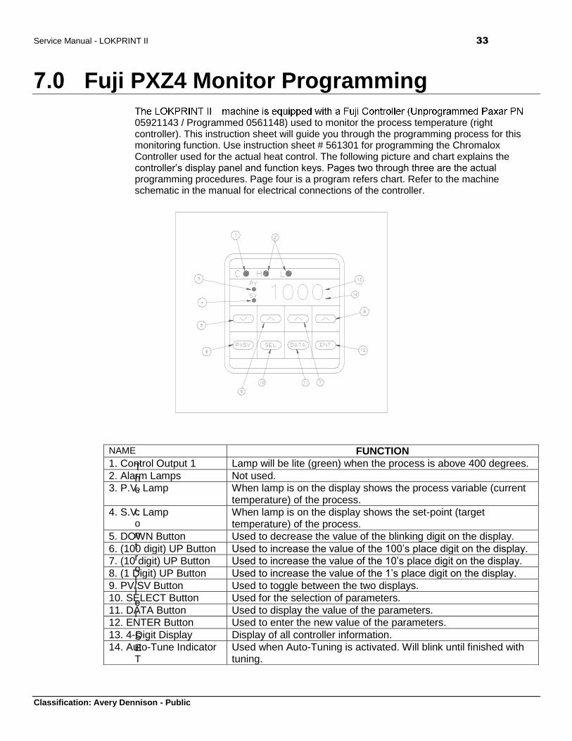
05921143 / Programmed 0561148) used to monitor the process temperature (right controller). This instruction sheet will guide you through the programming process for this monitoring function. Use instruction sheet # 561301 for programming the Chromalox Controller used for the actual heat control. The following picture and chart explains the controller’s display panel and function keys. Pages two through three are the actual programming procedures. Page four is a program refers chart. Refer to the machine schematic in the manual for electrical connections of the controller.
The controller SET
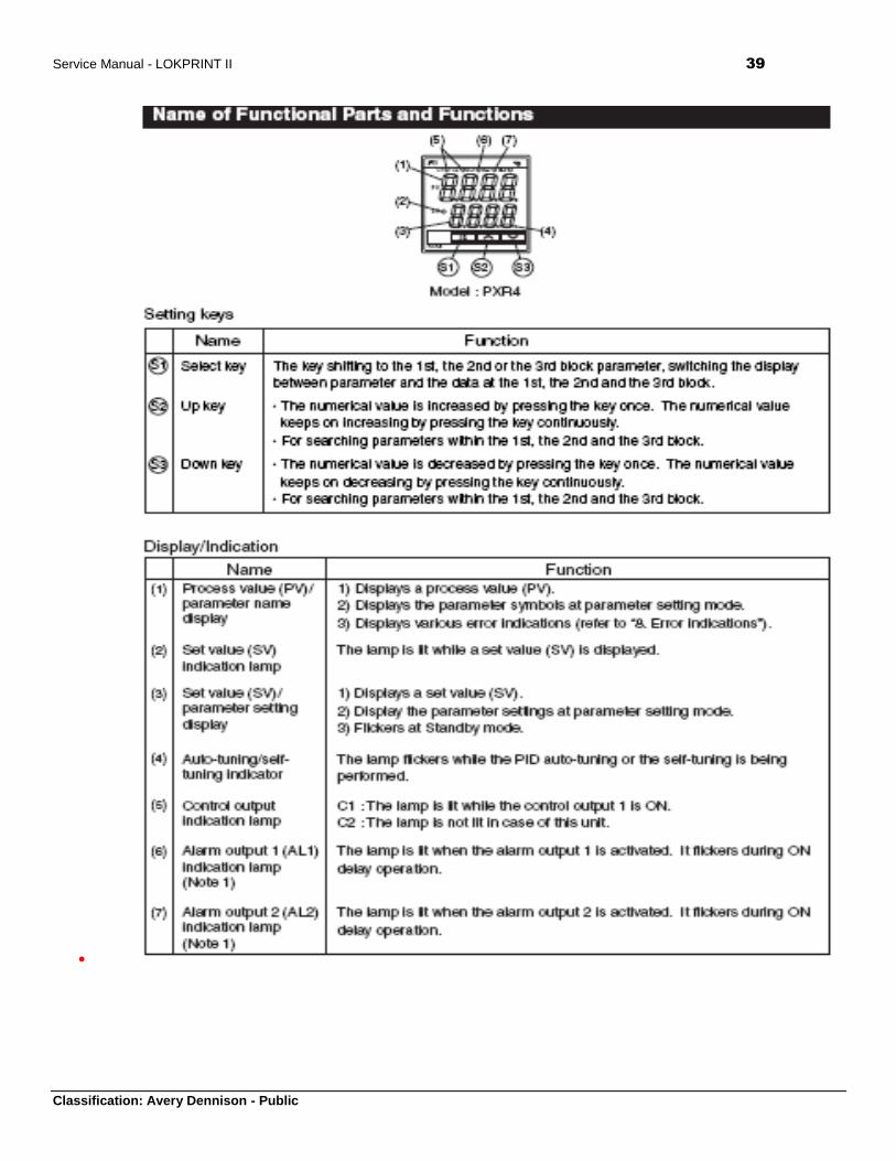
NAME FUNCTION
1. Control Output 1 Lamp will be lite (green) when the process is above 400 degrees.
2. Alarm Lamps Not used.
3. P.V. Lamp When lamp is on the display shows the process variable (current temperature) of the process.
4. S.V. Lamp When lamp is on the display shows the set-point (target temperature) of the process.
5. DOWN Button Used to decrease the value of the blinking digit on the display.
6. (100 digit) UP Button Used to increase the value of the 100’s place digit on the display.
7. (10 digit) UP Button Used to increase the value of the 10’s place digit on the display.
8. (1 Digit) UP Button Used to increase the value of the 1’s place digit on the display.
9. PV/SV Button Used to toggle between the two displays.
10. SELECT Button Used for the selection of parameters.
11. DATA Button Used to display the value of the parameters.
12. ENTER Button Used to enter the new value of the parameters.
13. 4-Digit Display Display of all controller information.
14. Auto-Tune Indicator Used when Auto-Tuning is activated. Will blink until finished with tuning.
34 Service Manual – LOKRPINT II
Classification: Avery Dennison - Public
POINT PROGRAMMING PROCEDURE:
1. Power on to display the PV.
2. Press the PV/SV button to activate the SV light.
3. Press the appropriate UP button or the DOWN button to increment or decrement each digit value until you have the desired low limit alarm (400) displayed.
4. Press the ENTER button.
5. Press the PV/SV button.
PROGRAMMING PROCEDURE:
1. Power on to display the PV.
2. Set the set point (lower limit alarm) using the above SETPOINT PROGRAMMING PROCEDURE.
3. Press the SEL button to display P.
4. Press the DATA button to display the data for P.
5. Press the appropriate UP button or the DOWN button to increment or decrement each digit value until 00.0 is displayed.
6. Press the ENTER button to display I.
7. Press the DATA button to display the data for I.
8. Press the appropriate UP button or the DOWN button to increment or decrement each digit value until 000 is displayed.
9. Press the ENTER button to display D.
10. Press the DATA button to display the data for D.
11. Press the appropriate UP button or the DOWN button to increment or decrement each digit value until 00.0 is displayed.
12. Press the ENTER button to display 7C.
13. Press the DATA button to display the data for 7C.
14. Press the appropriate UP button or the DOWN button to increment or decrement each digit value until 001 is displayed.
15. Press the ENTER button to display HYS.
16. Press the DATA button to display the data for HYS.
17. Press the appropriate UP button or the DOWN button to increment or decrement each digit value until 000 is displayed.
18. Press the ENTER button to display A7.
19. Press the DATA button to display the data for A7.
Service Manual - LOKPRINT II 35
Classification: Avery Dennison - Public
20. Press the appropriate UP button or the DOWN button to increment or decrement each digit value until 000 is displayed.
21. Press the ENTER button to display BAL.
22. Press the DATA button to display the data for BAL.
23. Press the appropriate UP button or the DOWN button to increment or decrement each digit value until 00.0 is displayed.
24. Press the ENTER button to display AR.
25. Press the DATA button to display the data for AR.
26. Press the appropriate UP button or the DOWN button to increment or decrement each digit value until 968 is displayed.
27. Press the ENTER button to display LOC.
28. Press the DATA button to display the data for LOC.
29. Press the appropriate UP button or the DOWN button to increment or decrement each digit value until 000 is displayed.
30. Press the ENTER button to display LOC.
31. Press and hold the SEL button to display P-N1.
32. Press the DATA button to display the data for P-N1.
33. Press the appropriate UP button or the DOWN button to increment or decrement each digit value until 002 is displayed.
34. Press the ENTER button to display P-N2.
35. Press the DATA button to display the data for P-N2.
36. Press the appropriate UP button or the DOWN button to increment or decrement each digit value until 002 is displayed.
37. Press the ENTER button to display P-DF.
38. Press the DATA button to display the data for P-DF.
39. Press the appropriate UP button or the DOWN button to increment or decrement each digit value until 05.0 is displayed.
40. Press the ENTER button to display P-SL.
41. Press the DATA button to display the data for P-SL.
42. Press the appropriate UP button or the DOWN button to increment or decrement each digit value until 000 is displayed.
43. Press the ENTER button to display P-SU.
44. Press the DATA button to display the data for P-SU.
45. Press the appropriate UP button or the DOWN button to increment or decrement each digit value until 1830 is displayed.
36 Service Manual – LOKRPINT II
Classification: Avery Dennison - Public
46. Press the ENTER button to display P-DP.
47. Press the DATA button to display the data for P-DP.
48. Press the appropriate UP button or the DOWN button to increment or decrement each digit value until 000 is displayed.
49. Press the ENTER button to display PUOF.
50. Press the DATA button to display the data for PUOF.
DO NOT CHANGE THE DATA OF PUOF AT THIS TIME, REFER TO THE CALIBRATION SECTION OF THIS INSTUCTION AND FUJI RECALIBRAITON IN THE CALIBRATION PROCEDURE SECTION OF INSTRUCTION SHEET 561301.
51. Press the ENTER button to display SUOF.
52. Press the DATA button to display the data for SUOF.
53. Press the appropriate UP button or the DOWN button to increment or decrement each digit value until 000 is displayed.
54. Press the ENTER button to display P-F.
55. Press the DATA button to display the data for P-F.
56. Press the appropriate UP button or the DOWN button to increment or decrement each digit value until OF is displayed.
57. Press the ENTER button to display FUSY.
58. Press the DATA button to display the data for FUSY.
59. Press the appropriate UP button or the DOWN button to increment or decrement each digit value until OFF is displayed.
60. Press the ENTER button to display DSP1.
61. Press the DATA button to display the data for DSP1.
62. Press the appropriate UP button or the DOWN button to increment or decrement each digit value until 049 is displayed.
63. Press the ENTER button to display DSP2.
64. Press the DATA button to display the data for DSP2.
65. Press the appropriate UP button or the DOWN button to increment or decrement each digit value until 253 is displayed.
66. Press the ENTER button to display DSP3.
67. Press the DATA button to display the data for DSP3.
68. Press the appropriate UP button or the DOWN button to increment or decrement each digit value until 248 is displayed.
69. Press the ENTER button to display DSP4.
70. Press the DATA button to display the data for DSP4.
Service Manual - LOKPRINT II 37
Classification: Avery Dennison - Public
71. Press the appropriate UP button or the DOWN button to increment or decrement each digit value until 255 is displayed.
72. Press the ENTER button to display DSP5.
73. Press the DATA button to display the data for DSP5.
74. Press the appropriate UP button or the DOWN button to increment or decrement each digit value until 131 is displayed.
75. Press the ENTER button to display DSP6.
76. Press the DATA button to display the data for DSP6.
77. Press the appropriate UP button or the DOWN button to increment or decrement each digit value until 139 is displayed.
78. Press the ENTER button to display DSP7.
79. Press the DATA button to display the data for DSP7.
80. Press the appropriate UP button or the DOWN button to increment or decrement each digit value until 125 is displayed.
81. Press the ENTER button to display DSP7.
82. Lock the Fuji by change LOC from a 0 to a 1.
83. Create and apply a label to the controller with “PN 561148” printed on it.
84. End of procedure.
CALIBRATION PROCEDURE:
1. Once the Fuji controller has been programmed and mounted in a machine THAT HAS A KNOWN CALIBRATED Chromolax controller allow the process to stabilize at SP while running fabric. REFER TO CALIBRATION PROCEDURE SECTION OF INSTRUCTION SHEET 561301.
2. If there is a difference between the Chromolax and the Fuji PVs first record the difference including the polarity then unlock the Fuji by changing it’s LOC value from a 1 to a 0.
3. Press and hold the SEL button for three seconds to display P-N1.
4. Press the SELECT button six times to display PUOF.
5. Press the DATA button to display the data for PUOF.
6. Change this number in the correct direction by the difference recorded in step number 2.
7. Press the ENTER button.
8. Press the PV/SV button twice to display the PV.
9. Confirm both controllers’ PV are equal while running stable at SP, if not repeat steps number 2 to 8.
10. Relock the FUJI by changing LOC back to a 1 from a 0.
38 Service Manual – LOKRPINT II
Classification: Avery Dennison - Public
11. Press the PV/SV button twice to display the PV.
12. End of Procedure.
REFER TO FUJI RECALIBRAITON IN THE CALIBRATION PROCEDURE SECTION OF INSTRUCTION SHEET 561301
8.0 Fuji PXZ4 to PXR4 Conversion
FUJI CONTROLLER PXZ-4 TO PXR-4 CONVERSION
PROGRAMMING SUPPLEMENT FOR
LOKPRINT I CONTROLLER 221303 Rev 2 or higher
LOKPRINT I MONITOR 221302 Rev 2 or higher
LOKPRINT II MONITOR 561305 Rev 1 or higher
The Fuji PXZ-4 series controllers (921142 and 921143) used in Avery Dennison LOKPRINTs has been replaced with Fuji PXR-4 series controllers. This supplemental instruction sheet will guide you through programming the device and provide the program settings for the LOKPRINT I Control (921143), Monitor (921142), and the LOKPRINT II Monitor (921142).
Note: The controller must be electrically wired following the wiring diagram found in the manual before proceeding with the programming procedures. The wiring is the same between the PXZ-4 and PXR-4 controller with exception of omitting the relay in the case of monitoring in both the LOKPRINT I & II. See attached schematics for changes / pinouts.
Use of the front panel to program device (reference the Name of Functional Parts and Functions on the next page):
Press and hold the SEL button 1 sec to get to 1st Block Parameters.
Press and hold the SEL button 2 sec to get to 2nd Block Parameters.
Press and hold the SEL button 3 sec to get to 3rd Block Parameters.
Press the UP or DOWN buttons to move up or down the menus.
Press the SEL button to select a variable, once selected the variable will flash.
Press the UP or DOWN buttons to change the value. Press the SEL button to enter the value or after three seconds of front panel inactivity the value is automatically stored in memory.
Service Manual - LOKPRINT II 39
Classification: Avery Dennison - Public
40 Service Manual – LOKRPINT II
Classification: Avery Dennison - Public
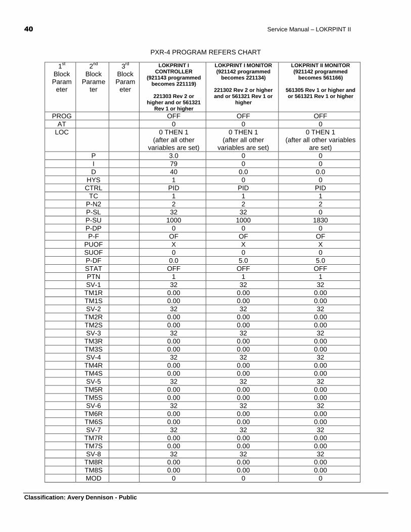
PXR-4 PROGRAM REFERS CHART
1st
Block Param
eter
2nd
Block
Parameter
3rd
Block Param
eter
LOKPRINT I CONTROLLER
(921143 programmed becomes 221119)
221303 Rev 2 or
higher and or 561321 Rev 1 or higher
LOKPRINT I MONITOR (921142 programmed
becomes 221134)
221302 Rev 2 or higher and or 561321 Rev 1 or
higher
LOKPRINT II MONITOR (921142 programmed
becomes 561166)
561305 Rev 1 or higher and or 561321 Rev 1 or higher
PROG OFF OFF OFF
AT 0 0 0
LOC 0 THEN 1 (after all other
variables are set)
0 THEN 1 (after all other
variables are set)
0 THEN 1 (after all other variables
are set)
P 3.0 0 0
I 79 0 0
D 40 0.0 0.0
HYS 1 0 0
CTRL PID PID PID
TC 1 1 1
P-N2 2 2 2
P-SL 32 32 0
P-SU 1000 1000 1830
P-DP 0 0 0
P-F OF OF OF
PUOF X X X
SUOF 0 0 0
P-DF 0.0 5.0 5.0
STAT OFF OFF OFF
PTN 1 1 1
SV-1 32 32 32
TM1R 0.00 0.00 0.00
TM1S 0.00 0.00 0.00
SV-2 32 32 32
TM2R 0.00 0.00 0.00
TM2S 0.00 0.00 0.00
SV-3 32 32 32
TM3R 0.00 0.00 0.00
TM3S 0.00 0.00 0.00
SV-4 32 32 32
TM4R 0.00 0.00 0.00
TM4S 0.00 0.00 0.00
SV-5 32 32 32
TM5R 0.00 0.00 0.00
TM5S 0.00 0.00 0.00
SV-6 32 32 32
TM6R 0.00 0.00 0.00
TM6S 0.00 0.00 0.00
SV-7 32 32 32
TM7R 0.00 0.00 0.00
TM7S 0.00 0.00 0.00
SV-8 32 32 32
TM8R 0.00 0.00 0.00
TM8S 0.00 0.00 0.00
MOD 0 0 0

Service Manual - LOKPRINT II 41
Classification: Avery Dennison - Public
P-N1 0 2 2
SV-L 32 32 32
SV-H 1000 1000 1000
DSP1 245 245 245
DSP2 255 255 255
DSP3 224 224 224
DSP4 45 45 45
DSP5 192 192 192
DSP6 1 1 1
DSP7 0 0 0
DSP8 0 0 0
DSP9 128 128 128
DSP10
255 255 255
DSP11
255 255 255
DSP12
255 255 255
DSP13
127 127 127

42 Service Manual – LOKRPINT II
Classification: Avery Dennison - Public
9.0 LOKPRINT I Fuji Controller Programming The LOKPRINT machine is equipped with a Fuji Controller (Paxar PN 921143) used to control the process temperature (left controller). This instruction sheet will guide you through the PROGRAMMING PROCEDURE, SET POINT PROGRAMMING, and CALIBRATION PROCEDURE for the controlling function. Use instruction sheet # 221302 for programming the Fuji Controller used to monitor the process temperature. The following picture and chart explains the controller’s display panel and function keys. Refer to the machine schematic 221195 in the manual for electrical connections of the controller.
NAME FUNCTION
1. Control Output 1 Lamp will be lite (green) when the heaters are on.
2. Alarm Lamps Not used.
3. P.V. Lamp When lamp is on the display shows the process variable (current temperature) of the process.
4. S.V. Lamp When lamp is on the display shows the set-point (target temperature) of the process.
5. DOWN Button Used to decrease the value of the blinking digit on the display.
6. (100 digit) UP Button Used to increase the value of the 100’s place digit on the display.
7. (10 digit) UP Button Used to increase the value of the 10’s place digit on the display.
8. (1 Digit) UP Button Used to increase the value of the 1’s place digit on the display.
9. PV/SV Button Used to toggle between the two displays.
10. SELECT Button Used for the selection of parameters.
11. DATA Button Used to display the value of the parameters.
12. ENTER Button Used to enter the new value of the parameters.
13. 4-Digit Display Display of all controller information.
14. Auto-Tune Indicator Used when Auto-Tuning is activated. Will blink until finished with tuning.
Service Manual - LOKPRINT II 43
Classification: Avery Dennison - Public
The controller must be electrically wired following the wiring diagram found in the manual before proceeding with the programming procedures. The PROGRAMMING PROCEDURE, SETPOINT PROGRAMMING PROCEDURE, and the CALIBRATION PROCEDURE are used to set the process temperature and variable controls needed to maintain same.
PROGRAMMING PROCEDURE:
Use this procedure in conjunction with the SETPOINT PROGRAMMING PROCEDURE to set the process temperature and variable controls needed to maintain same.
1. Power on.
2. Set the set point (process temperature) using the below SETPOINT PROGRAMMING PROCEDURE.
3. Press the SEL button to display P.
4. Press the DATA button to display the data for P.
5. Press the appropriate UP button or the DOWN button to increment or decrement each digit value until 3.0 is displayed.
6. Press the ENTER button.
7. Press the DATA button to display the data for I.
8. Press the appropriate UP button or the DOWN button to increment or decrement each digit value until 79 is displayed.
9. Press the ENTER button.
10. Press the DATA button to display the data for D.
11. Press the appropriate UP button or the DOWN button to increment or decrement each digit value until 40.0 is displayed.
12. Press the ENTER button.
13. Press the DATA button to display the data for 7C.
14. Press the appropriate UP button or the DOWN button to increment or decrement each digit value until 1 is displayed.
15. Press the ENTER button.
16. Press the DATA button to display the data for HYS.
17. Press the appropriate UP button or the DOWN button to increment or decrement each digit value until 1 is displayed.
18. Press the ENTER button.
19. Press the DATA button to display the data for A7.
20. Press the appropriate UP button or the DOWN button to increment or decrement each digit value until 0 is displayed.
21. Press the ENTER button.
22. Press the DATA button to display the data for BAL.
23. Press the appropriate UP button or the DOWN button to increment or decrement each digit value until 20.0 is displayed.
24. Press the ENTER button.
44 Service Manual – LOKRPINT II
Classification: Avery Dennison - Public
25. Press the DATA button to display the data for AR.
26. Press the appropriate UP button or the DOWN button to increment or decrement each digit value until 5 is displayed.
27. Press the ENTER button.
28. Press and hold the SEL button for three seconds to display P-N1.
29. Press the DATA button to display the data for P-N1.
30. Press the appropriate UP button or the DOWN button to increment or decrement each digit value until 0 is displayed.
31. Press the ENTER button.
32. Press the DATA button to display the data for P-N2.
33. Press the appropriate UP button or the DOWN button to increment or decrement each digit value until 2 is displayed.
34. Press the ENTER button.
35. Press the DATA button to display the data for P-DF.
36. Press the appropriate UP button or the DOWN button to increment or decrement each digit value until 0.0 is displayed.
37. Press the ENTER button.
38. Press the DATA button to display the data for P-SL.
39. Press the appropriate UP button or the DOWN button to increment or decrement each digit value until 32 is displayed.
40. Press the ENTER button.
41. Press the DATA button to display the data for P-SU.
42. Press the appropriate UP button or the DOWN button to increment or decrement each digit value until 1000 is displayed.
43. Press the ENTER button.
44. Press the DATA button to display the data for P-DP.
45. Press the appropriate UP button or the DOWN button to increment or decrement each digit value until 0 is displayed.
46. Press the ENTER button.
47. Press the DATA button to display the data for PUOF.
48. Press the appropriate UP button or the DOWN button to increment or decrement each digit value until 0 is displayed.
49. Press the ENTER button.
50. Press the DATA button to display the data for SUOF.
51. Press the appropriate UP button or the DOWN button to increment or decrement each digit value until 0 is displayed.
52. Press the ENTER button.
53. Press the DATA button to display the data for P-F.

Service Manual - LOKPRINT II 45
Classification: Avery Dennison - Public
54. Press the appropriate UP button or the DOWN button to increment or decrement each digit value until oF is displayed.
55. Press the ENTER button.
56. Press the DATA button to display the data for FUSY.
57. Press the appropriate UP button or the DOWN button to increment or decrement each digit value until ON is displayed.
58. Press the ENTER button.
59. Press the DATA button to display the data for DSP1.
60. Press the appropriate UP button or the DOWN button to increment or decrement each digit value until 49 is displayed.
61. Press the ENTER button.
62. Press the DATA button to display the data for DSP2.
63. Press the appropriate UP button or the DOWN button to increment or decrement each digit value until 253 is displayed.
64. Press the ENTER button.
65. Press the DATA button to display the data for DSP3.
66. Press the appropriate UP button or the DOWN button to increment or decrement each digit value until 248 is displayed.
67. Press the ENTER button.
68. Press the DATA button to display the data for DSP4.
69. Press the appropriate UP button or the DOWN button to increment or decrement each digit value until 255 is displayed.
70. Press the ENTER button.
71. Press the DATA button to display the data for DSP5.
72. Press the appropriate UP button or the DOWN button to increment or decrement each digit value until 131 is displayed.
73. Press the ENTER button.
74. Press the DATA button to display the data for DSP6.
75. Press the appropriate UP button or the DOWN button to increment or decrement each digit value until 139 is displayed.
76. Press the ENTER button.
77. Press the DATA button to display the data for DSP7.
78. Press the appropriate UP button or the DOWN button to increment or decrement each digit value until 125 is displayed.
79. Press the ENTER button.
80. Press and hold the SEL button for three seconds to display P.
81. Press the SEL button eight times to display LOC.
82. Press the DATA button to display the LOC data.
46 Service Manual – LOKRPINT II
Classification: Avery Dennison - Public
83. Press the appropriate UP button or the DOWN button to increment or decrement each digit value until 001 is displayed.
84. Press the ENTER button.
85. Press the PV/SV button twice to display the PV.
86. Create and apply a label to the controller with the “PN 221119” printed on it.
87. End of Procedure.
SETPOINT PROGRAMMING PROCEDURE:
Use this procedure to set the desired set value temperature (SV).
1. Power on.
2. Press the PV/SV button to activate the SV light.
3. Press the appropriate UP button or the DOWN button to increment or decrement each digit value until you have the desired process temperature (415) displayed.
4. Press the ENTER button.
5. Press the PV/SV button.
CALIBRATION PROCEDURE:
Use this procedure if a discrepancy exists between the actual anvil temperature and the process temperature (PV).
1. Power on.
2. Set the set point (process temperature) using the above SETPOINT PROGRAMMING PROCEDURE.
3. Allow the process to arrive at SV temperature and stabilize.
4. measure and record the actual anvil temperature on the center top.
5. If there is a difference between the actual measured temperature and the SV first record the difference including the polarity then unlock the controller used to control the process temperature (left controller) by changing it’s LOC from a 1 back to a 0.
6. Press and hold the SEL button for three seconds to display P-N1.
7. Press the SELECT button six times to display PUOF.
8. Press the DATA button to display the data for PUOF.
9. Change this number by the difference recorded in step number 5 (if the actual temperature is high increase PUOF, if the actual temperature is low decrease PUOF).
10. Press the ENTER button.
11. Press the PV/SV button twice to display the PV.
12. Allow the process to arrive at SV temperature and stabilize.
13. Confirm the actual anvil temperature and the PV are equal, if not repeat steps 4 to 13.
14. Relock the controller by changing LOC from a 0 to a 1.
15. End of procedure.

Service Manual - LOKPRINT II 47
Classification: Avery Dennison - Public
PROCESS CONTROL PROGRAM REFERS CHART
P 3.0 P-SU 1000
I 79 P-DP 0
D 40 PUOF 0
7C 1 SUOF 0
HYS 1 P-F Of
A7 0 FUSY ON
BAL 20 DSP1 49
AR 5 DSP2 253
LOC 1 DSP3 248
P-N1 0 DSP4 255
P-N2 2 DSP5 131
P-DF 0.0 DSP6 139
P-SL 32 DSP7 125
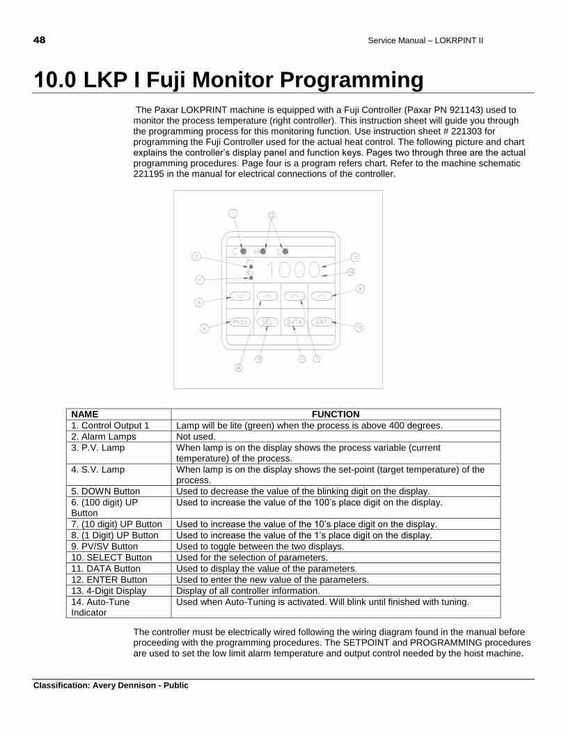
48 Service Manual – LOKRPINT II
Classification: Avery Dennison - Public
10.0 LKP I Fuji Monitor Programming The Paxar LOKPRINT machine is equipped with a Fuji Controller (Paxar PN 921143) used to monitor the process temperature (right controller). This instruction sheet will guide you through the programming process for this monitoring function. Use instruction sheet # 221303 for programming the Fuji Controller used for the actual heat control. The following picture and chart explains the controller’s display panel and function keys. Pages two through three are the actual programming procedures. Page four is a program refers chart. Refer to the machine schematic 221195 in the manual for electrical connections of the controller.
NAME FUNCTION
1. Control Output 1 Lamp will be lite (green) when the process is above 400 degrees.
2. Alarm Lamps Not used.
3. P.V. Lamp When lamp is on the display shows the process variable (current temperature) of the process.
4. S.V. Lamp When lamp is on the display shows the set-point (target temperature) of the process.
5. DOWN Button Used to decrease the value of the blinking digit on the display.
6. (100 digit) UP Button
Used to increase the value of the 100’s place digit on the display.
7. (10 digit) UP Button Used to increase the value of the 10’s place digit on the display.
8. (1 Digit) UP Button Used to increase the value of the 1’s place digit on the display.
9. PV/SV Button Used to toggle between the two displays.
10. SELECT Button Used for the selection of parameters.
11. DATA Button Used to display the value of the parameters.
12. ENTER Button Used to enter the new value of the parameters.
13. 4-Digit Display Display of all controller information.
14. Auto-Tune Indicator
Used when Auto-Tuning is activated. Will blink until finished with tuning.
The controller must be electrically wired following the wiring diagram found in the manual before proceeding with the programming procedures. The SETPOINT and PROGRAMMING procedures are used to set the low limit alarm temperature and output control needed by the hoist machine.
Service Manual - LOKPRINT II 49
Classification: Avery Dennison - Public
SETPOINT PROGRAMMING PROCEDURE:
1. Power on.
2. Press the PV/SV button to activate the SV light.
3. Press the appropriate UP button or the DOWN button to increment or decrement each digit value until you have the desired low limit alarm (400) displayed.
4. Press the ENTER button.
5. Press the PV/SV button.
PROGRAMMING PROCEDURE:
1. Power on.
2. Set the set point (lower limit alarm) using the above SETPOINT PROGRAMMING PROCEDURE.
3. Press the SEL button to display P.
4. Press the DATA button to display the data for P.
5. Press the appropriate UP button or the DOWN button to increment or decrement each digit value until 0.0 is displayed.
6. Press the ENTER button.
7. Press the DATA button to display the data for I.
8. Press the appropriate UP button or the DOWN button to increment or decrement each digit value until 0 is displayed.
9. Press the ENTER button.
10. Press the DATA button to display the data for D.
11. Press the appropriate UP button or the DOWN button to increment or decrement each digit value until 0.0 is displayed.
12. Press the ENTER button.
13. Press the DATA button to display the data for 7C.
14. Press the appropriate UP button or the DOWN button to increment or decrement each digit value until 1 is displayed.
15. Press the ENTER button.
16. Press the DATA button to display the data for HYS.
17. Press the appropriate UP button or the DOWN button to increment or decrement each digit value until 0 is displayed.
18. Press the ENTER button.
19. Press the DATA button to display the data for A7.
20. Press the appropriate UP button or the DOWN button to increment or decrement each digit value until 0 is displayed.
21. Press the ENTER button.
Avery Dennison 170 Monarch Lane Miamisburg, OH 45342 1-800-543-6650 (In the U.S.A.) 1-800-387-4740 (In Canada) www.averydennison.com
028028