Service Manual · 9.3 Maintenance Method for Normal Malfunction..... 35. Service Manual Table of...
51
Model: GEH09AA-K6DNA1E/I GEH12AA-K6DNA1E/I GEH18AA-K6DNA1E/I Service Manual Change for life GREE ELECTRIC APPLIANCES, INC. OF ZHUHAI
Transcript of Service Manual · 9.3 Maintenance Method for Normal Malfunction..... 35. Service Manual Table of...
Model: GEH09AA-K6DNA1E/IGEH12AA-K6DNA1E/IGEH18AA-K6DNA1E/I (Refrigerant R32)
Service Manual
Change for life
GREE ELECTRIC APPLIANCES, INC. OF ZHUHAI
Service Manual
Table of Contents
Table of Contents
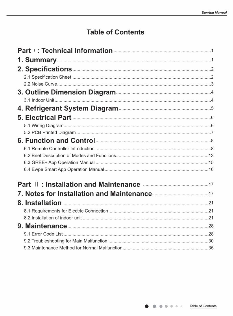
Part Ⅰ : Technical Information ............................................................................1
1. Summary ........................................................................................................................1
2. Specifications ............................................................................................................2
2.1 Specification Sheet .............................................................................................................22.2 Noise Curve ........................................................................................................................3
3. Outline Dimension Diagram ..........................................................................4
3.1 Indoor Unit ..........................................................................................................................4
4. Refrigerant System Diagram ........................................................................5
5. Electrical Part.............................................................................................................6
5.1 Wiring Diagram ...................................................................................................................65.2 PCB Printed Diagram .........................................................................................................7
6. Function and Control ..........................................................................................86.1 Remote Controller Introduction .........................................................................................86.2 Brief Description of Modes and Functions ........................................................................136.3 GREE+ App Operation Manual ........................................................................................156.4 Ewpe Smart App Operation Manual .................................................................................16
Part Ⅱ : Installation and Maintenance ...................................................17
7. Notes for Installation and Maintenance ............................................17
8. Installation ..................................................................................................................21
8.1 Requirements for Electric Connection ..............................................................................218.2 Installation of indoor unit ..................................................................................................21
9. Maintenance ..............................................................................................................28
9.1 Error Code List .................................................................................................................289.2 Troubleshooting for Main Malfunction ..............................................................................309.3 Maintenance Method for Normal Malfunction ...................................................................35

Service Manual
Table of Contents Table of Contents
10. Exploded View and Parts List ..................................................................37
10.1 Indoor Unit ........................................................................................................................37
11. Removal Procedure ...........................................................................................39
11.1 Removal Procedure of Indoor Unit ...................................................................................39
Appendix: ............................................................................................................................43
Appendix 1: Reference Sheet of Celsius and Fahrenheit ........................................................43Appendix 2: Configuration of Connection Pipe .........................................................................43Appendix 3: Pipe Expanding Method .......................................................................................44Appendix 4: List of Resistance for Temperature Sensor ..........................................................45

1Technical Information
Service Manual
1. Summary
Part Ⅰ : Technical Information
Indoor Unit
GEH09AA-K6DNA1E/IGEH12AA-K6DNA1E/IGEH18AA-K6DNA1E/I
Remote Controller
YAA1FB8(WiFi)
32
6
WiFi

2 Technical Information
Service Manual
2. Specifications2.1 Specification Sheet
ModelConsole
GEH09AA-K6DNA1E/I GEH12AA-K6DNA1E/I GEH18AA-K6DNA1E/IProduct Code CV010N02100 CV010N02200 CV010N02300Rated Voltage V~ 220-240 220-240 220-240Rated Frequency Hz 50 50 50Phases 1 1 1Cooling Capacity W 2700 3500 5200Heating Capacity W 2800 3750 5330Air Flow Volume (SH/H/M/L) m3/h 500/430/410/370/330/280/250 600/520/480/440/400/360/280 700/650/580/520/460/410/320Dehumidifying Volume L/h 0.8 1.2 3.8Fan Type Centrifugal Centrifugal CentrifugalFan Diameter-height mm Φ370X80 Φ370X80 Φ370X80Fan Motor Speed(SH/H/HM/M/LM/L/SL) (Cool)
rpm 650/560/530/480/430/370/320 750/650/600/550/500/450/350 840/800/720/650/580 /530/410810/770/690/620/550 /500/380
Fan Motor Speed(SH/H/HM/M/LM/L/SL) (Heat)
rpm 650/560/530/480/430 /370/320 750/650/600/550/500/450/350 930/840/760/690/620 /570/480850/800/720/650/580 /530/470
Fan Motor Power Output W 30 30 30Fan motor running current A 0.15 0.15 0.15Evaporator Material Aluminum Fin-copper Tube Aluminum Fin-copper Tube Aluminum Fin-copper TubeEvaporator Pipe Diameter mm Φ7 Φ7 Φ7Evaporator Number of Rows 2 2 2Evaporator Fin Pitch mm 1.3 1.3 1.3Evaporator Length(L) X Height(H) X Width(W)
mm511X25.4X400
511X25.4X400 511X25.4X400
Motor Model MP24EB/MP24AE MP24EB/MP24AE MP24EB/MP24AEOverload Protector 1.5/1.5 1.5/1.5 1.5/1.5Motor Full Load Amp(FLA) A 3.15 3.15 3.15Sound Pressure Level(SH/H/HM/M/LM/L/SL)
dB(A) 40/36/34/32/30/26/23 42/40/38/36/34/31/25 47/45/42/40/37/35/31
Sound Power Level(SH/H/HM/M/LM/L/SL)
dB(A) 52/48/46/44/42/38/34 52/50/48/46/44/41/35 57/55/52/50/47/45/41
Outline Dimension (WXHXD) mm 700X600X215 700X600X215 700X600X215Package Carton Dimension (LXWXH)
mm 785X682X280 785X682X280 785X682X280
Package Dimension (LXWXH) mm 788X697X283 788X697X283 788X697X283Net Weight kg 15.5 15.5 15.5Gross Weight kg 18.5 18.5 18.5Liquid pipe mm Φ6 Φ6 Φ6Gas Pipe(to indoor unit) mm Φ9.52 Φ9.52 Φ12
The above data is subject to change without notice. Please refer to the nameplate of the unit.
3Technical Information
Service Manual
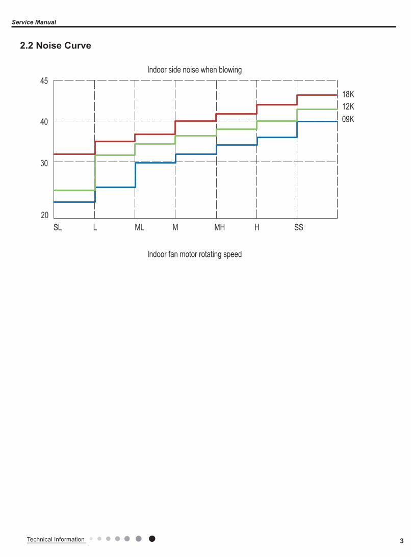
2.2 Noise Curve
20
30
40
45Indoor side noise when blowing
Indoor fan motor rotating speed
SSHMHMMLLSL
09K12K18K
4 Technical Information
Service Manual
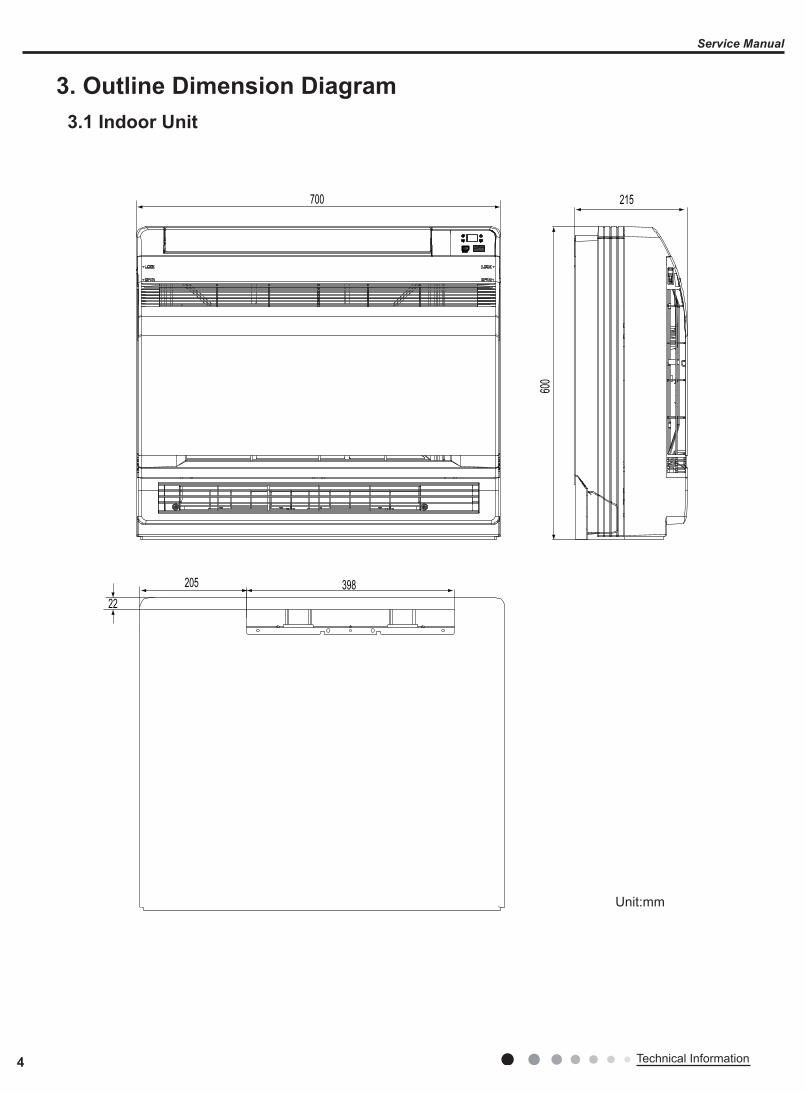
3. Outline Dimension Diagram3.1 Indoor Unit
700 215
600
39820522
Unit:mm
5Technical Information
Service Manual
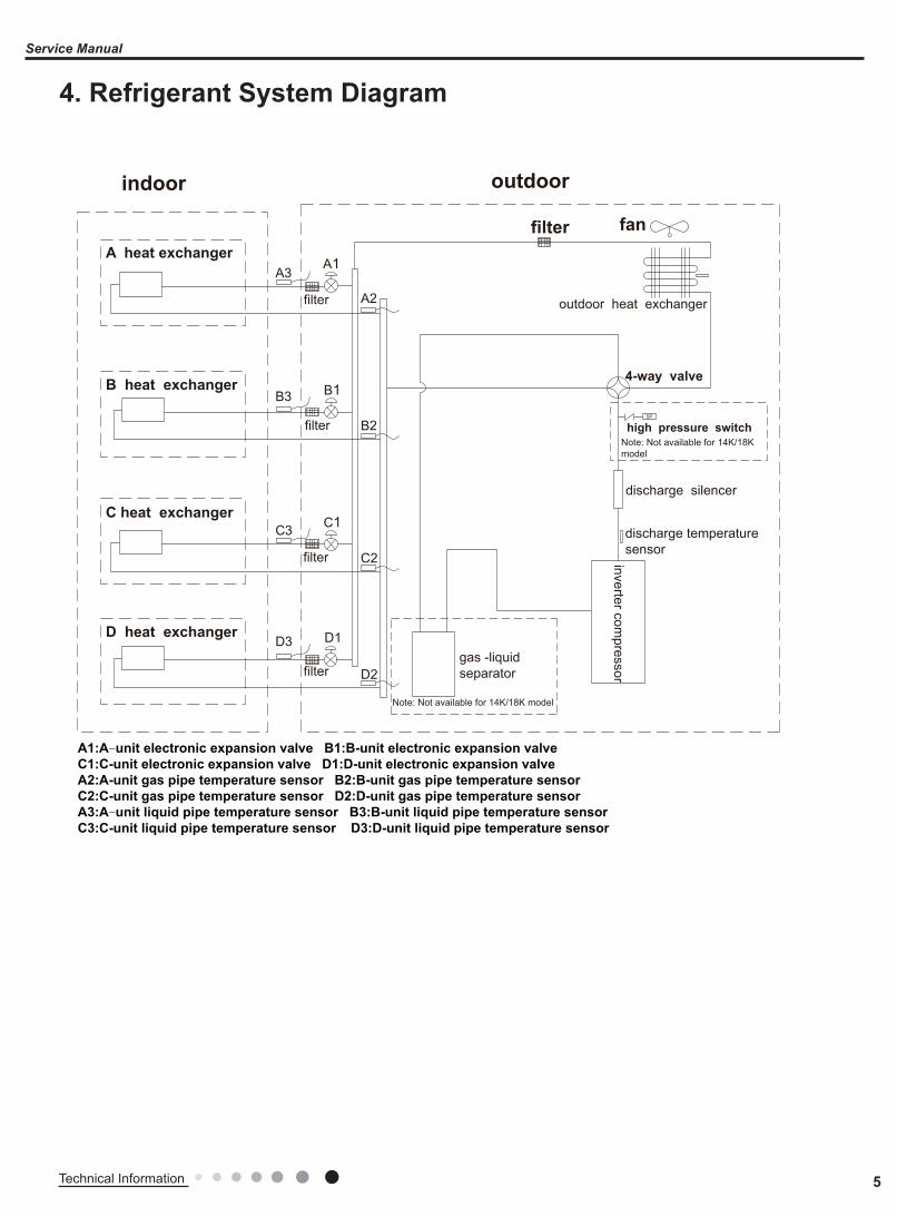
4. Refrigerant System Diagram
outdoorindoor
D1
C1
B1
A1
filterA heat exchanger
gas -liquid separator
inverter compressor
discharge silencer
discharge temperature sensor
SP
4-way valve
outdoor heat exchanger
fan
high pressure switch
B heat exchanger
C heat exchanger
D heat exchanger
filter
filter
filter
filter
Note: Not available for 14K/18K model
C2
C3
D3
D2
B3
B2
A2
A3
A1:A-unit electronic expansion valve B1:B-unit electronic expansion valveC1:C-unit electronic expansion valve D1:D-unit electronic expansion valveA2:A-unit gas pipe temperature sensor B2:B-unit gas pipe temperature sensorC2:C-unit gas pipe temperature sensor D2:D-unit gas pipe temperature sensorA3:A-unit liquid pipe temperature sensor B3:B-unit liquid pipe temperature sensorC3:C-unit liquid pipe temperature sensor D3:D-unit liquid pipe temperature sensor
Note: Not available for 14K/18K model
6 Technical Information
Service Manual
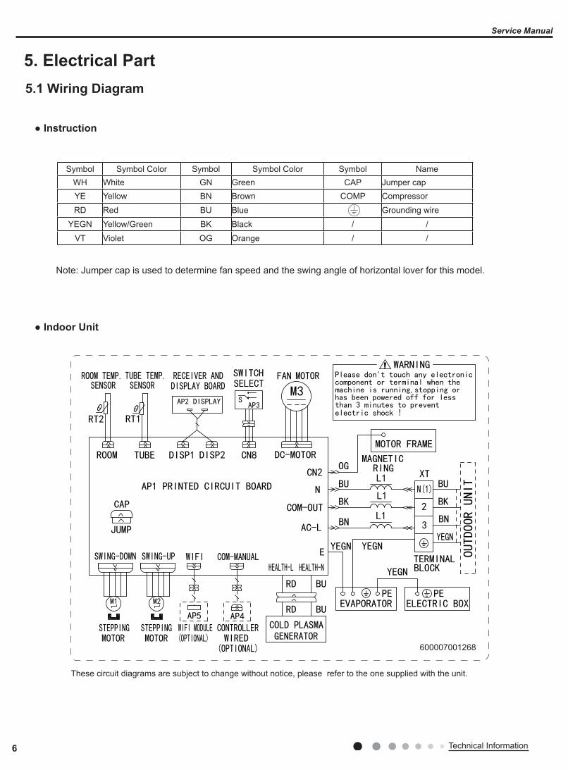
5. Electrical Part5.1 Wiring Diagram
● Indoor Unit
● Instruction
Symbol Symbol Color Symbol Symbol Color Symbol NameWH White GN Green CAP Jumper capYE Yellow BN Brown COMP Compressor
RD Red BU Blue Grounding wire
YEGN Yellow/Green BK Black / /
VT Violet OG Orange / /
Note: Jumper cap is used to determine fan speed and the swing angle of horizontal lover for this model.
600007001268
These circuit diagrams are subject to change without notice, please refer to the one supplied with the unit.
7Technical Information
Service Manual
1234567
8 9 10 11 12 13 14
15
16
17
18
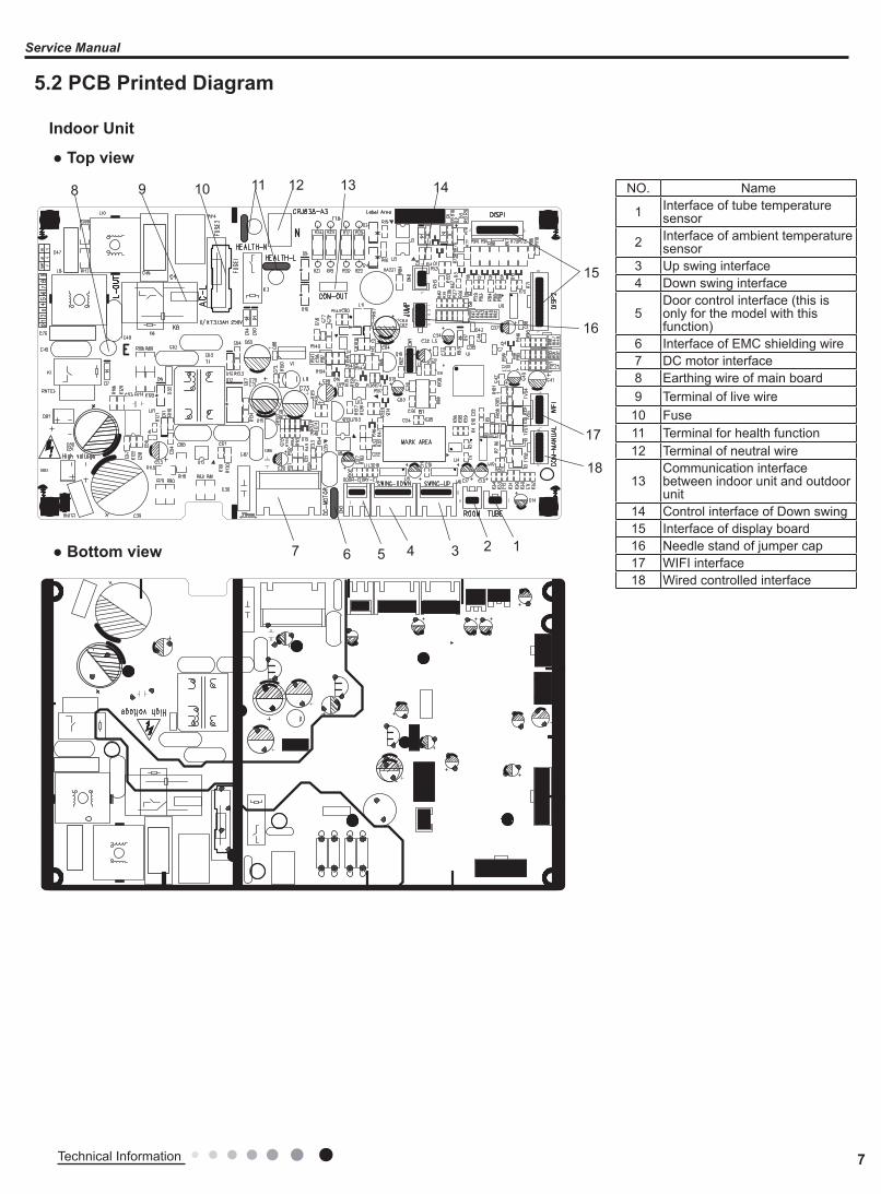
5.2 PCB Printed Diagram
Indoor Unit
● Top view
● Bottom view
NO. Name
1 Interface of tube temperature sensor
2 Interface of ambient temperature sensor
3 Up swing interface 4 Down swing interface
5Door control interface (this is only for the model with this function)
6 Interface of EMC shielding wire 7 DC motor interface 8 Earthing wire of main board 9 Terminal of live wire
10 Fuse11 Terminal for health function12 Terminal of neutral wire
13Communication interface between indoor unit and outdoor unit
14 Control interface of Down swing 15 Interface of display board 16 Needle stand of jumper cap17 WIFI interface 18 Wired controlled interface
8 Technical Information
Service Manual
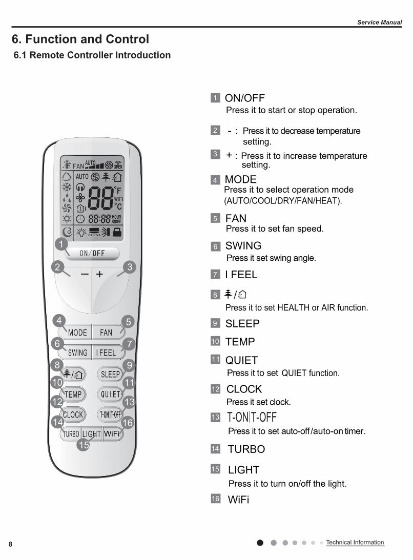
6. Function and Control6.1 Remote Controller Introduction
T-ON T-OFF
1
7
Press it to set HEALTH or AIR function.8
I FEEL
/
4
3
2
5
6
11
13
12
16
10
14
9
15
Press it to start or stop operation.ON/OFF
MODE
+
-
Press it to select operation mode(AUTO/COOL/DRY/FAN/HEAT).
: Press it to increase temperature setting.
: Press it to decrease temperature setting.
FAN
Press it set swing angle.
QUIET
SWING
CLOCK
WiFi
TEMP
TURBO
SLEEP
LIGHT
Press it to set fan speed.
Press it to set
Press it to set auto-off /auto-on timer.
Press it set clock.
3
15
54
14
7
1312
98
1110
2
1
6
Press it to turn on/off the light.
QUIET function.
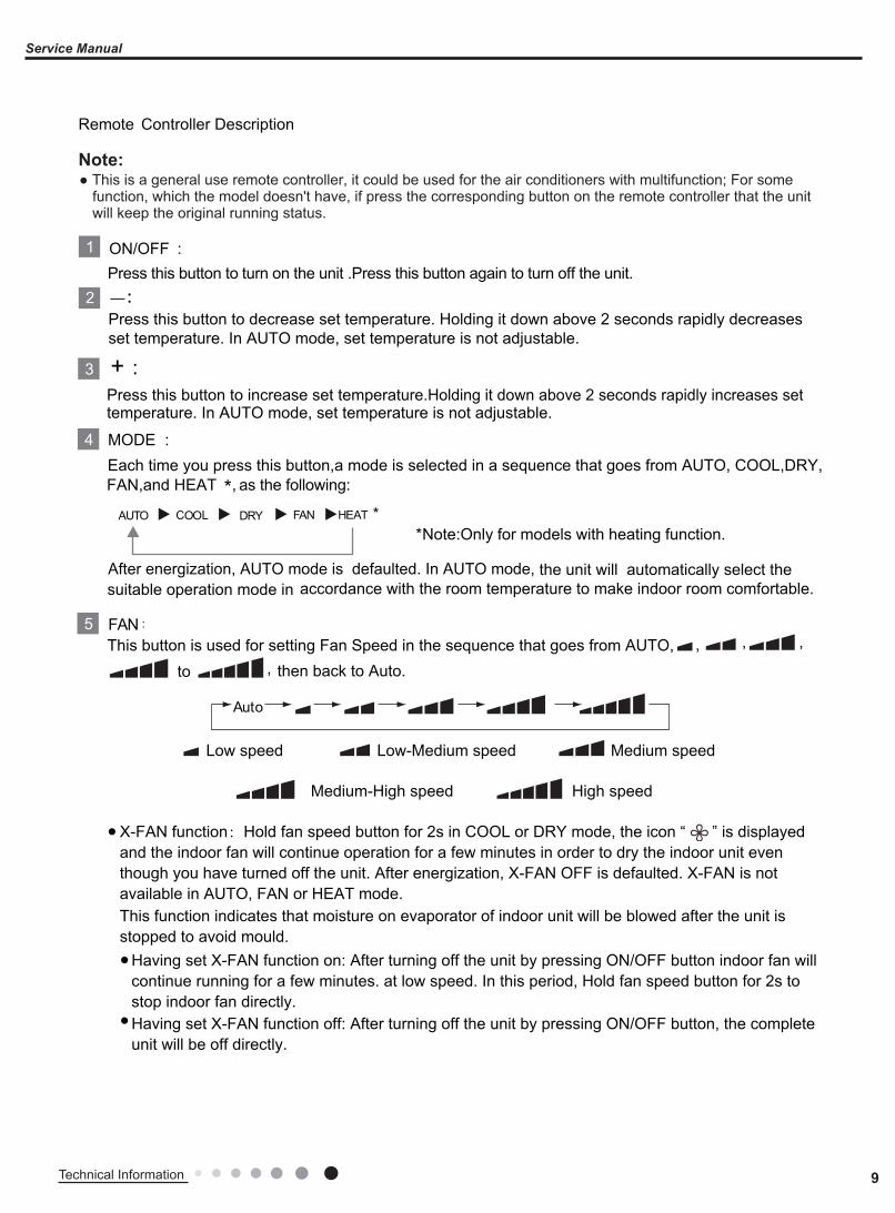
Remote Controller Description
16WiFi
9Technical Information
Service Manual
This function indicates that moisture on evaporator of indoor unit will be blowed after the unit is stopped to avoid mould.
X-FAN function:Hold fan speed button for 2s in COOL or DRY mode, the icon “ ” is displayed and the indoor fan will continue operation for a few minutes in order to dry the indoor unit even though you have turned off the unit. After energization, X-FAN OFF is defaulted. X-FAN is not available in AUTO, FAN or HEAT mode.
●
Having set X-FAN function on: After turning off the unit by pressing ON/OFF button indoor fan will continue running for a few minutes. at low speed. In this period, Hold fan speed button for 2s to stop indoor fan directly.
●
Having set X-FAN function off: After turning off the unit by pressing ON/OFF button, the complete unit will be off directly.
●
Remote Controller Description
ON/OFF :
MODE :
+ :
AUTO COOL DRY FAN HEAT **Note:Only for models with heating function.
After energization, AUTO mode is defaulted. In AUTO mode,
the unit will automatically select the suitable operation mode in accordance with the room temperature to make indoor room comfortable.
This button is used for setting Fan Speed in the sequence that goes from AUTO, ,FAN :
1
4
3
2
5
Press this button to turn on the unit .Press this button again to turn off the unit.
Press this button to decrease set temperature. Holding it down above 2 seconds rapidly decreases set temperature. In AUTO mode, set temperature is not adjustable.
Press this button to increase set temperature.Holding it down above 2 seconds rapidly increases set
Auto
Medium speedLow-Medium speedLow speed
High speedMedium-High speed
Each time you press this button,a mode is selected in a sequence that goes from AUTO, COOL,DRY, *, as the following:
to then back to Auto.,, ,
temperature. In AUTO mode, set temperature is not adjustable.
FAN,and HEAT
Note:● This is a general use remote controller, it could be used for the air conditioners with multifunction; For some
function, which the model doesn't have, if press the corresponding button on the remote controller that the unitwill keep the original running status.
10 Technical Information
Service Manual
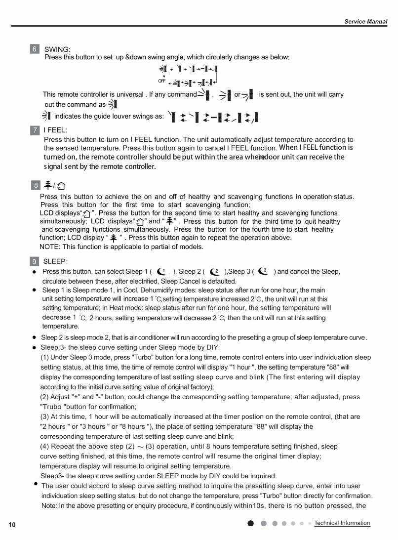
6Press this button to set up &down swing angle, which circularly changes as below:
OFF
This remote controller is universal . If any command , or is sent out, the unit will carry
indicates the guide louver swings as:
Press this button to turn on I FEEL function. The unit automatically adjust temperature according tothe sensed temperature. Press this button again to cancel I FEEL function.
I FEEL:
SWING:
7
out the command as
SLEEP:9Press this button, can select Sleep 1 ( ), Sleep 2 ( ),Sleep 3 ( ) and cancel the Sleep,circulate between these, after electrified, Sleep Cancel is defaulted.Sleep 1 is Sleep mode 1, in Cool, Dehumidify modes: sleep status after run for one hour, the mainunit setting temperature will increase 1
Sleep 3- the sleep curve setting under Sleep mode by DIY:(1) Under Sleep 3 mode, press "Turbo" button for a long time, remote control enters into user individuation sleepsetting status, at this time, the time of remote control will display "1 hour ", the setting temperature "88" will
(2) Adjust "+" and "-" button, could change the corresponding setting temperature, after adjusted, press"Trubo "button for confirmation;(3) At this time, 1 hour will be automatically increased at the timer postion on the remote control, (that are
(4) Repeat the above step (2) (3) operation, until 8 hours temperature setting finished, sleep curve setting finished, at this time, the remote control will resume the original timer display;
display the corresponding temperature of last setting sleep curve and blink (The first entering will displayaccording to the initial curve setting value of original factory);
"2 hours " or "3 hours " or "8 hours "), the place of setting temperature "88" will display the corresponding temperature of last setting sleep curve and blink;
temperature display will resume to original setting temperature.Sleep3- the sleep curve setting under SLEEP mode by DIY could be inquired:The user could accord to sleep curve setting method to inquire the presetting sleep curve, enter into user individuation sleep setting status, but do not change the temperature, press "Turbo" button directly for confirmation.Note: In the above presetting or enquiry procedure, if continuously within10s, there is no button pressed, the
,setting temperature increased 2 , the unit will run at thissetting temperature; In Heat mode: sleep status after run for one hour, the setting temperature willdecrease 1 , 2 hours, setting temperature will decrease 2 , then the unit will run at this settingtemperature.Sleep 2 is sleep mode 2, that is air conditioner will run according to the presetting a group of sleep temperature curve.
Press this button to achieve the on and off of healthy and scavenging functions in operation status.Press this button for the first time to start scavenging function;LCD displays“ ”. Press the button for the second time to start healthy and scavenging functions simultaneously; LCD displays“ ” and “ ” . Press this button for the third time to quit healthy and scavenging functions simultaneously. Press the button for the fourth time to start healthy
function; LCD display “ ” . Press this button again to repeat the operation above.NOTE: This function is applicable to partial of models.
/8
When I FEEL function is turned on, the remote controller should be put within the area where indoor unit can receive the
.rellortnoc etomer eht yb tnes langis
11Technical Information
Service Manual
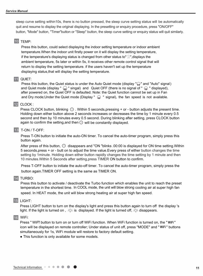
Press this button, could select displaying the indoor setting temperature or indoor ambienttemperature.When the indoor unit firstly power on it will display the setting temperature,if the temperature's displaying status is changed from other status to" ",displays theambient temperature, 5s later or within 5s, it receives other remote control signal that will return to display the setting temperature. if the users haven't set up the temperature displaying status,that will display the setting temperature.
10 TEMP:
● This function is only available for some models.
" " eht ,no denrut si noitcnuf iFiW nehW .noitcnuf iFiW ffo nrut ro no nrut ot nottub " iFiW " sserP WiFiicon will be displayed on remote controller; Under status of unit off, press "MODE" and " " buttons simultaneously for 1s, WiFi module will restore to factory default setting.
WiFi
CLOCK :
Press T-ON button to initiate the auto-ON timer. To cancel the auto-timer program, simply press thisbutton again.After press of this button, disappears and "ON "blinks .00:00 is displayed for ON time setting.Within
12
13
Press T-OFF button to initiate the auto-off timer. To cancel the auto-timer program, simply press the
Press CLOCK button, blinking . Within 5 seconds,pressing + or - button adjusts the present time.Holding down either button above 2 seconds increases or decreases the time by 1 minute every 0.5 second and then by 10 minutes every 0.5 second. During blinking after setting, press CLOCK buttonagain to confirm the setting,and then
LIGHT:15Press LIGHT button to turn on the display's light and press this button again to turn off the display 's light. If the light is turned on , is displayed. If the light is turned off, disappears.
TURBO:14
WiFi:16
Press this button to activate / deactivate the Turbo function which enables the unit to reach the presettemperature in the shortest time. In COOL mode, the unit will blow strong
QUIET:11Press this button, the Quiet status is under the Auto Quiet mode (display and "Auto"" " signal)and Quiet mode (display " " singal) and Quiet OFF (there is no signal of " " displayed),after powered on, the Quiet OFF is defaulted. Note: the Quiet function cannot be set up in Fan and Dry mode;Under the Quiet mode (Display " " signal), the fan speed is not available.
will be constantly displayed.
T-ON / T-OFF:
5 seconds,press + or - butt on to adjust the time value.Every press of either button changes the timesetting by 1minute. Holding down either button rapidly changes the time setting by 1 minute and then 10 minutes.Within 5 Seconds after setting,press TIMER ON button to confirm.
cooling air at super high fan speed. In HEAT mode, the unit will blow strong heating air at super high fan speed.
button again.TIMER OFF setting is the same as TIMER ON.
sleep curve setting within10s, there is no button pressed, the sleep curve setting status will be automaticallyquit and resume to display the original displaying. In the presetting or enquiry procedure, press "ON/OFF"button, "Mode" button, "Timer"button or "Sleep" button, the sleep curve setting or enquiry status will quit similarly.
12 Technical Information
Service Manual
●
●
●●●
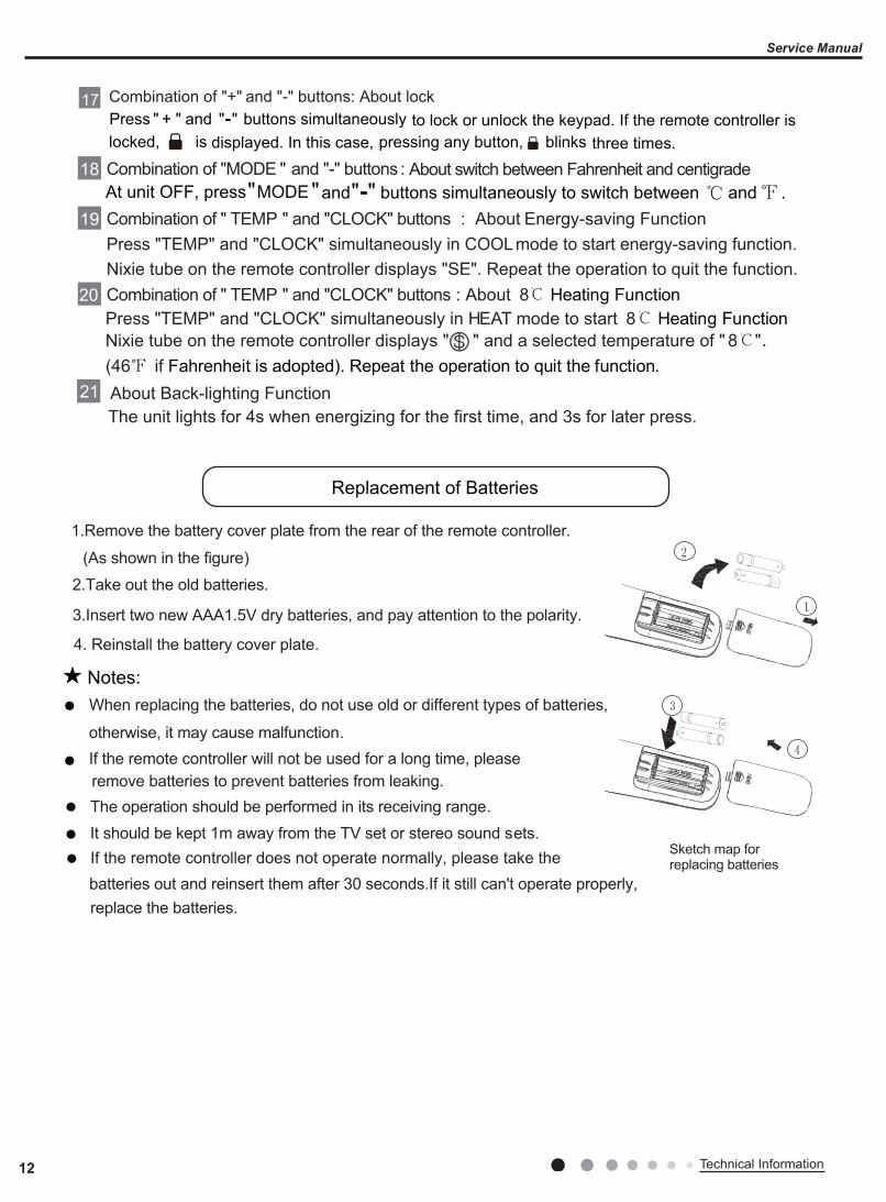
1.Remove the battery cover plate from the rear of the remote controller.
(As shown in the figure)2.Take out the old batteries.
3.Insert two new AAA1.5V dry batteries, and pay attention to the polarity.
4. Reinstall the battery cover plate.
When replacing the batteries, do not use old or different types of batteries,
If the remote controller will not be used for a long time, please otherwise, it may cause malfunction.
remove batteries to prevent batteries from leaking. The operation should be performed in its receiving range.It should be kept 1m away from the TV set or stereo sound sets.If the remote controller does not operate normally, please take the batteries out and reinsert them after 30 seconds.If it still can't operate properly,
Notes:
replace the batteries.
Sketch map for replacing batteries
At unit OFF, press "MODE"and " - " buttons simultaneously to switch between and .
About Back-lighting Function21
Combination of "MODE " and "-" buttons :18 About switch between Fahrenheit and centigrade
Press "TEMP" and "CLOCK" simultaneously in COOL mode to start energy-saving function.Nixie tube on the remote controller displays "SE". Repeat the operation to quit the function.
Combination of " TEMP " and "CLOCK" buttons : About Energy-saving Function19
Press "TEMP" and "CLOCK" simultaneously in HEAT mode to start
The unit lights for 4s when energizing for the first time, and 3s for later press.
8℃ Heating Function.Nixie tube on the remote controller displays " " and a selected temperature of " 8℃"
(46 if Fahrenheit is adopted). Repeat the operation to quit the function.
Combination of " TEMP " and "CLOCK" buttons : About 8℃ Heating Function20
Replacement of Batteries
Press " + " and "-" buttons simultaneously to lock or unlock the keypad. If the remote controller is displayed. In this case, pressing any button, blinks three times.
Combination of "+" and "-" buttons: About lock17
locked, is
13Technical Information
Service Manual
6.2 Brief Description of Modes and Functions1. Cooling mode(1) Under this mode, the fan and the up swing will operate at setting status. The temperature setting range is 16~30ºC.(2) The unit is stopped because of malfunction of outdoor unit or protection. The indoor unit keeps original operation status and theerror code is displayed.(3) Indoor unit is stopped due to mode shock.2. Drying mode(1) Under this mode, the fan operates at low speed and the swing operates at setting status. The temperature setting range is16~30ºC.(2) The unit is stopped because of malfunction of outdoor unit or protection. The indoor unit keeps original operation status and theerror code is displayed.3. Heating mode(1) Under this mode, the temperature setting range is 16~30ºC.(2) Working condition and process for heatingWhen the unit is turned on under heating mode, the indoor unit turns to cold air prevention status. When the unit is turned off and theindoor unit has been started up before, the indoor unit blows the residual heat.(3) Protection function: When the compressor is stopped due to malfunction under heating mode, the indoor unit blows theresidual heat.(4) Blow residual heatWhen the unit stops operation as it reaches the temperature point, indoor unit will continue to run for 60s. The fan speed cant beswitched during blowing residual heat period. The upper horizontal louver will turn to the defaulted position in cooling. When the unitoperates under heating mode or auto heating mode, compressor will be turned on and the corresponding electric expansion valve ismore than 65 and the unit stops operation during the operation status of indoor unit. The upper horizontal louver will turn to thedefaulted position in heating mode. The indoor unit operates at low speed for 10s and then the unit stops operation.(5) Defrosting, oil-returningAs it received the signal of defrosting and oil-returning from outdoor unit, the upper horizontal louver will turn to the minimum angle incooling. 10s later, the in door fan stop operation. During defrosting and oil-returning process and they are quitted within 5mins, allmalfunctions for indoor tube temperature sensor wont be detected.4. Working process for AUTO mode (Mode judgment will be performed every 30s)Under AUTO mode, standard cooling Tpreset=25ºC (77ºF), standard heating Tpreset=20ºC (68ºF), and standard fan Tpreset= 25ºC(77ºF).(1) When Tamb≥26ºC (79ºF), the unit operation in cooling mode;(2) Heating pump unit: When Tamb≤19ºC (66ºF), the unit operates in heating mode;(3) Cooling only unit: Tamb≤19ºC (66ºF), the unit operates in fanmode;(4) When 19ºC<Tindoor amb.<26ºC, if it turns to auto mode as the unit is turned on for the first time the unit will operates at auto fanmode. If it switch to auto mode from other modes, the unit will keep previous operation mode (when it turns to dry mode, the unitoperates at auto fan mode).(5) Protection functionProtection function is the same as that in cooling or heating mode.5. Fan modeUnder fan mode, only indoor fan and swing operates. When it operates at auto fan speed, it will operate according to auto fan speedcondition in cooling.6. Mode shockIf the mode shock is 1 which is received by indoor unit from outdoor unit, the loads of indoor unit (indoor unit, auxiliary heating,swing)stop operation and the error code is displayed. The mode sent to outdoor unit is still remote control receiving mode. The unit will beturned off during mode shock.If timer ON is reached, and the mode shock is 1 which is received by indoor unit from outdoor unit, the loads of indoor unit (indoor unit,auxiliary heating, swing) stop operation and the error code is displayed. The mode sent to outdoor unit is still remote control receiving mode.7. Other control7.1 BuzzerUpon energization or availably operating the unit or remote controller, the buzzer will give out a beep.7.2 Auto buttonIf this button is pressed, the unit will operate in AUTO mode and indoor fan will operate at auto speed; meanwhile, the swing motoroperates. Press this button again to turn off the unit.7.3 8 ºC heating functionUnder heating mode, press TEMP+CLOCK buttons simultaneously. Under this mode, “cold air prevention protection” will be shielded.

14 Technical Information
Service Manual
7.4 I FEEL functionWhen I FEEL command is received, the controller will operate according to the ambient temperature sent by the remote controller (Fordefrosting and cold blow prevention, the unit operates according to the ambient temperature sensed by the air conditioner). The remote controller will send ambient temperature data to the controller every 10min. When the data has not been received after 11mins,the unit will operate according to the temperature sensed by the air conditioner. If I FEEL function is not selected, the ambienttemperature will be that sensed by the air conditioner. I FEEL function will not to be memorized.7.5 Timer functionGeneral timer and clock timer functions are compatible by equipping remote controller with different functions.(1)General TimerTimer ON can be set at unit OFF. If selected ON time is reached, the unit will start to operate according to previous setting status. Time setting range is 0.5-24hr in 30-minute increments.Timer OFF can be set at unit ON. If selected OFF time is reached, the unit will stop operation. Time setting range is 0.5-24hr in30-minute increments.(2)Clock Timer Timer ON If timer ON is set during operation of the unit, the unit will continue to operate. If timer ON is set at unit OFF, upon ON time reaches the unit will start to operate according to previous setting status. Timer OFF If timer OFF is set at unit OFF, the system will keep standby status. If timer OFF is set at unit ON, upon OFF time reaches the unit will stop operation. Timer Change Although timer has been set, the unit still can be turned on/off by pressing ON/OFF button of remote controller. You can also set the timer once again, and then the unit will operate according to the last setting. If timer ON and timer OFF are set at the same time during operation of the unit, the unit will keep operating at current status till OFF time reaches. If timer ON and timer OFF are set at the same time at unit OFF, the unit will keep stop till ON time reaches. In the future’s every day, the system will operate according to presetting mode till OFF.7.6 Sleep functionThis mode is only valid in cooling and heating modes. The unit will select proper sleep curve to operate according to different settemperature.7.7 Compulsory defrosting functionWhen the unit is turned on in heating by remote controller and the set temperature is 16oC, press “+,-,+,-,+,-”continuously within 5s, the indoor unit turns to compulsory defrosting setting and it will send compulsory defrosting mode to outdoor unit.When indoor unit received the compulsory defrosting signal from outdoor unit, the indoor unit will quit from the compulsory defrostingsetting and it will cancel to send compulsory defrosting mode to outdoor unit.7.8 Refrigerant recovery functionTurn to Freon recovery mode: After the unit is energized for 5min, and the unit is turned on at 16ºC under cooling mode, press lightbutton on remote controller for 3 times successively within 3s to turn to Freon recovery mode. Fo is displayed and it will send Freonrecovery mode to outdoor unit.Quit from Freon recovery mode:After it turns to Freon mode, if it receives any signal from remote controller or it turns to Freonrecovery mode for 25 mins, it will quit from Freon recovery mode.Turn to the action for Freon recovery mode: indoor unit will be turned on in cooling mode. The fan speed is super-high fan speed andthe set temperature is 16oC. The horizontal louver will turn to the minimum operation angle.Quit the action for Freon recovery mode: The indoor fan operates at the previous set status by remote controller.7.9 Pilot run functionWhen the set temperature is 30oC under cooling mode, press “+,-,+,-,+,-”continuously within 3s, the indoor unit turns to pilot run setting mode and it will send pilot run mode to outdoor unit.Pilot run mode: it operates under cooling mode and “dd” is displayed.Quit the pilot run mode and indoor unit cancels “dd” display. If it receives “wrong wire connection of malfunction of expansion valve”from outdoor unit, “dn” will be displayed.
15Installation and Maintenance
Service Manual
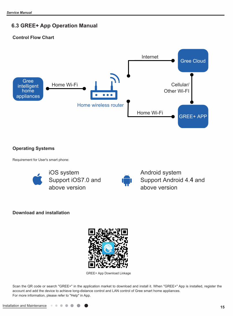
6.3 GREE+ App Operation Manual
Control Flow Chart
Download and installation
Operating Systems
Requirement for User's smart phone:
Scan the QR code or search "GREE+" in the application market to download and install it. When "GREE+" App is installed, register the account and add the device to achieve long-distance control and LAN control of Gree smart home appliances. For more information, please refer to "Help" in App.
Internet
Cellular/Other Wi-FI
Home Wi-FiHome wireless router
Home Wi-FiGree
Gree Cloud
GREE+ APP
intelligenthome
appliances
iOS systemSupport iOS7.0 and above version
Android systemSupport Android 4.4 and above version
GREE+ App Download Linkage

16 Installation and Maintenance
Service Manual
Control Flow Chart
Download and installation
Operating Systems
Requirement for User's smart phone:
Scan the QR code or search "Ewpe Smart" in the application market to download and install it. When "Ewpe Smart" App is installed, register the account and add the device to achieve long-distance control and LAN control of smart home appliances. For more information, please refer to "Help" in App.
6.4 Ewpe Smart App Operation Manual
iOS systemSupport iOS7.0 and above version
Android systemSupport Android 4.4 and above version
App Download Linkage
Internet
Cellular/Other Wi-FI
Home Wi-FiHome wireless router
Home Wi-Fi
Cloud
APP
intelligenthome
appliances

17Installation and Maintenance
Service Manual
1. Select the installation location according to the require-ment of this manual.(See the requirements in installation part)2. Handle unit transportation with care; the unit should not be carried by only one person if it is more than 20kg.3. When installing the indoor unit and outdoor unit, a suffi-cient fixing bolt must be installed; make sure the installation support is firm.4. Ware safety belt if the height of working is above 2m.5. Use equipped components or appointed components dur-ing installation.6. Make sure no foreign objects are left in the unit after fin-ishing installation.
Electrical Safety Precautions:
7. Notes for Installation and Maintenance
Safety Precautions: Important!Please read the safety precautions carefully before installation and maintenance.The following contents are very important for installation and maintenance.
Please follow the instructions below.
●The installation or maintenance must accord with the instructions.●Comply with all national electrical codes and local electrical codes.●Pay attention to the warnings and cautions in this manual.●All installation and maintenance shall be performed by distributor or qualified person.●All electric work must be performed by a licensed technician according to local regulations and the instructions given in this manual.●Be caution during installation and maintenance. Prohibit incorrect operation to prevent electric shock, casualty and other accidents.
1. Cut off the power supply of air conditioner before checking and maintenance.2. The air condition must apply specialized circuit and prohibit share the same circuit with other appliances.3. The air conditioner should be installed in suitable location and ensure the power plug is touchable.4. Make sure each wiring terminal is connected firmly during installation and maintenance.5. Have the unit adequately grounded. The grounding wire cant be used for other purposes.6. Must apply protective accessories such as protective boards, cable-cross loop and wire clip.7. The live wire, neutral wire and grounding wire of power supply must be corresponding to the live wire, neutral wire and grounding wire of the air conditioner. 8. The power cord and power connection wires cant be pressed by hard objects.9. If power cord or connection wire is broken, it must be replaced by a qualified person.
1. Avoid contact between refrigerant and fire as it generates poisonous gas; Prohibit prolong the connection pipe by welding.2. Apply specified refrigerant only. Never have it mixed with any other refrigerant. Never have air remain in the refrigerant line as it may lead to rupture or other hazards.3. Make sure no refrigerant gas is leaking out when installation is completed.4. If there is refrigerant leakage, please take sufficient measure to minimize the density of refrigerant.5. Never touch the refrigerant piping or compressor without wearing glove to avoid scald or frostbite.
Warnings
Refrigerant Safety Precautions:
Improper installation may lead to fire hazard, explosion, electric shock or injury.
Installation Safety Precautions:
Part Ⅱ : Installation and Maintenance
10. If the power cord or connection wire is not long enough, please get the specialized power cord or connection wire from the manufacture or distributor. Prohibit prolong the wire by yourself.11. For the air conditioner without plug, an air switch must be installed in the circuit. The air switch should be all-pole parting and the contact parting distance should be more than 3mm.12. Make sure all wires and pipes are connected properly and the valves are opened before energizing.13. Check if there is electric leakage on the unit body. If yes, please eliminate the electric leakage.14. Replace the fuse with a new one of the same specification if it is burnt down; dont replace it with a cooper wire or conducting wire.15. If the unit is to be installed in a humid place, the circuit breaker must be installed.
18 Installation and Maintenance
Service Manual
Safety Precautions for Installing and Relocating the Unit:
WarningsTo ensure safety, please be mindful of the following precautions.
1. When installing or relocating the unit, be sure to keep the refrigerant circuit free from air or substances other than the specified refrigerant.Any presence of air or other foreign substance in the refrigerant circuit will cause system pressure rise or compressor rupture, resulting in injury.2.When installing or moving this unit, do not charge the refrigerant which is not comply with that on the nameplate or unqualified refrigerant.Otherwise, it may cause abnormal operation, wrong action, mechanical malfunction or even series safety accident.3.When refrigerant needs to be recovered during relocating or repairing the unit, be sure that the unit is running in cooling mode.Then, fully close the valve at high pressure side (liquid valve).About 30-40 seconds later, fully close the valve at low pressure side (gas valve), immediately stop the unit and disconnect power. Please note that the time for refrigerant recovery should not exceed 1 minute. If refrigerant recovery takes too much time, air may be sucked in and cause pressure rise or compressor rupture, resulting in injury. 4.During refrigerant recovery, make sure that liquid valve and gas valve are fully closed and power is disconnected before detaching the connection pipe. If compressor starts running when stop valve is open and connection pipe is not yet connected, air will be sucked in and cause pressure rise or compressor rupture, resulting in injury.5.When installing the unit, make sure that connection pipe is securely connected before the compressor starts running.If compressor starts running when stop valve is open and connection pipe is not yet connected, air will be sucked in and cause pressure rise or compressor rupture, resulting in injury.6.Prohibit installing the unit at the place where there may be leaked corrosive gas or flammable gas.If there leaked gas around the unit, it may cause explosion and other accidents.7.Do not use extension cords for electrical connections. If the electric wire is not long enough, please contact a local service center authorized and ask for a proper electric wire.Poor connections may lead to electric shock or fire.8.Use the specified types of wires for electrical connections between the indoor and outdoor units. Firmly clamp the wires so that their terminals receive no external stresses.Electric wires with insufficient capacity, wrong wire connections and insecure wire terminals may cause electric shock or fire.
Safety Precautions for Refrigerant●To realize the function of the air conditioner unit, a special refrigerant circulates in the system. The used refrigerant is the fluoride R32,which is specially cleaned. The refrigerant is flammable and inodorous. Furthermore, it can leads to explosion under certain conditions. But the flammability of the refrigerant is very low. It can be ignited only by fire.●Compared to common refrigerants, R32 is a nonpolluting refrigerant with no harm to the ozonosphere. The influence upon the greenhouse effect is also lower. R32 has got very good thermodynamic features which lead to a really high energy efficiency. The units therefore need a less filling.
WARNING:●Do not use means to accelerate the defrosting process or to clean, other than those recommended by the manufacture.Should repair be necessary,contact your nearest authorized Service Centre. Any repairs carried out by unqualified personnel may be dangerous. The appliance shall be stored in a room without continuously operating ignition sources. (for example:open flames , an operating gas appliance or an operating electric heater.)●Do not pierce or burn.●Appliance shall be installed, operated and stored in a room with a floor area larger than 4m (or 6m ).●Appliance filled with flammable gas R32. For repairs, strictly follow manufacturers instructions only.Be aware that refrigrants not contain odour.●Read specialists manual.

19Installation and Maintenance
Service Manual
Safety Operation of Flammable RefrigerantQualification requirement for installation and maintenance man●All the work men who are engaging in the refrigeration system should bear the valid certification awarded by the authoritative organization and the qualification for dealing with the refrigeration system recognized by this industry. If it needs other technician to maintain and repair the appliance, they should be supervised by the person who bears the qualification for using the flammable refrigerant.●It can only be repaired by the method suggested by the equipments manufacturer.
Installation notes●The air conditioner is not allowed to use in a room that has running fire (such as fire source,working coal gas ware, operating heater).●It is not allowed to drill hole or burn the connection pipe.●The air conditioner must be installed in a room that is larger than the minimum room area.The minimum room area is shown on the nameplate or following table a.●Leak test is a must after installation.
table a - Minimum room area(m2)
Maintenance notes●Check whether the maintenance area or the room area meet the requirement of the nameplate.— Its only allowed to be operated in the rooms that meet the requirement of the nameplate.●Check whether the maintenance area is well-ventilated.— The continuous ventilation status should be kept during the operation process.●Check whether there is fire source or potential fire source in the maintenance area.— The naked flame is prohibited in the maintenance area; and the “no smoking” warning board should be hanged.●Check whether the appliance mark is in good condition.— Replace the vague or damaged warning mark.
Welding●If you should cut or weld the refrigerant system pipes in the process of maintaining, please follow the steps as below:a. Shut down the unit and cut power supplyb. Eliminate the refrigerantc. Vacuumingd. Clean it with N2 gase. Cutting or weldingf. Carry back to the service spot for welding●Make sure that there isnt any naked flame near the outlet of the vacuum pump and its well-ventilated.●The refrigerant should be recycled into the specialized storage tank.
Filling the refrigerant●Use the refrigerant filling appliances specialized for R32. Make sure that different kinds of refrigerant wont contaminate with each other.●The refrigerant tank should be kept upright at the time of filling refrigerant.●Stick the label on the system after filling is finished (or havent finished).●Dont overfilling.●After filling is finished, please do the leakage detection before test running; another time of leak detection should be done when its removed.
Safety instructions for transportation and storage●Please use the flammable gas detector to check before unload and open the container.●No fire source and smoking.●According to the local rules and laws.

20 Installation and Maintenance
Service Manual
Main Tools for Installation and Maintenance
1. Level meter, measuring tape
4. Electroprobe
7. Electronic leakage detector
10. Pipe pliers, pipe cutter
2. Screw driver
5. Universal meter
8. Vacuum pump
11. Pipe expander, pipe bender
3. Impact drill, drill head, electric drill
6. Torque wrench, open-end wrench, inner hexagon spanner
9. Pressure meter
12. Soldering appliance, refrigerant container
21Installation and Maintenance
Service Manual
8. Installation
1. Safety Precaution(1) Must follow the electric safety regulations when installing the unit.(2) If the supply cord is damaged, it must be replaced by the manufacturer or its service agent or a similarly qualified person in order to (avoid a hazard.(3) According to the local safety regulations, use qualified power supply circuit and air switch.(4) A air switch having a contact separation of at least 3mm in all poles should be fixed in fixed wiring.(5) The appliance shall be installed in accordance with national wiring regulation.(6) The air switch must have the functions of magnetic tripping and heat tripping in order to prevent short circuit or overload. Please install the air switch with suitable capacity according to the sheet below.(7) Make sure the power supply matches with the requirement of air conditioner.Unstable power supply or incorrect wiring may result in electric shock, fire hazard or malfunction. Please install proper power supply cables before using the air conditioner.(8) Properly connect the live wire, neutral wire and grounding wire of power socket.(9) Be sure to cut off the power supply before proceeding any work related to electric safety.(10) Do not put through the power before finishing installation.
2. Grounding Requirement(1) The air conditioner is first class electric appliance. It must be properly grounded with specialized grounding device by a professional. Please make sure it is always grounded effectively, otherwise it may cause electric shock.(2) The yellow-green wire in air conditioner is grounding wire, which can't be used for other purposes.(3) The grounding resistance should comply with national electric safety regulations.
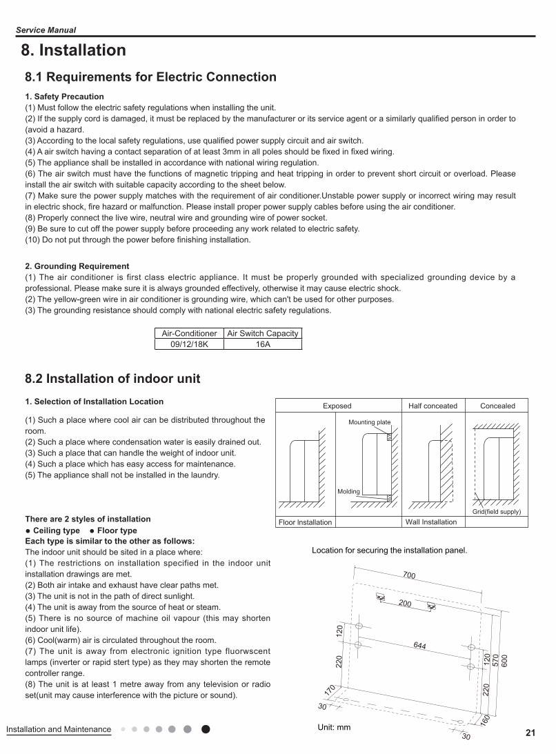
1. Selection of Installation Location
There are 2 styles of installation● Ceiling type ● Floor typeEach type is similar to the other as follows:The indoor unit should be sited in a place where:(1) The restrictions on installation specified in the indoor unit installation drawings are met.(2) Both air intake and exhaust have clear paths met.(3) The unit is not in the path of direct sunlight.(4) The unit is away from the source of heat or steam.(5) There is no source of machine oil vapour (this may shorten indoor unit life).(6) Cool(warm) air is circulated throughout the room.(7) The unit is away from electronic ignition type fluorwscent lamps (inverter or rapid stert type) as they may shorten the remote controller range.(8) The unit is at least 1 metre away from any television or radio set(unit may cause interference with the picture or sound).
(1) Such a place where cool air can be distributed throughout the room.(2) Such a place where condensation water is easily drained out.(3) Such a place that can handle the weight of indoor unit.(4) Such a place which has easy access for maintenance.(5) The appliance shall not be installed in the laundry.
8.1 Requirements for Electric Connection
8.2 Installation of indoor unit
Air-Conditioner Air Switch Capacity09/12/18K 16A
Exposed
Floor lnstallation Wall Installation
Molding
Mounting plate
Half conceated Concealed
Grid(field supply)
Location for securing the installation panel.
Unit: mm 160
30
570
700
120
220
170
30
644
120
220
600
200
22 Installation and Maintenance
Service Manual
45
45 45 4560
75
75
75
75
45
Left back piping
gnipip mottob thgiRgnipip mottob tfeL
Wall
Right back piping Left/right piping
Cautions for installation where air conditioner troubleis liable tooccur.Where there is toomuch of oil area.Where it is acid base area.Where there is irregular electrical supply.
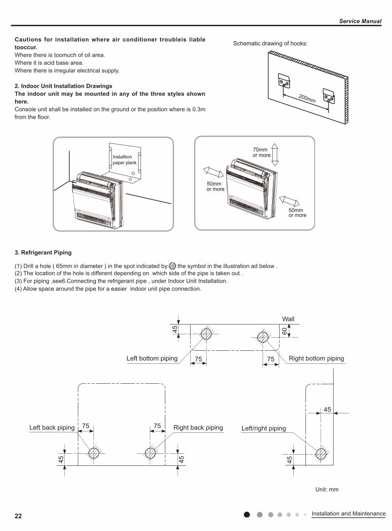
2. Indoor Unit Installation DrawingsThe indoor unit may be mounted in any of the three styles shown here.Console unit shall be installed on the ground or the position where is 0.3m from the floor.
Schematic drawing of hooks:
200mm
50mmor more
70mmor more
50mmor more
Installtionpaper plank
3. Refrigerant Piping
(1) Drill a hole ( 65mm in diameter ) in the spot indicated by the symbol in the illustration ad below .(2) The location of the hole is different depending on which side of the pipe is taken out .(3) For piping ,see6.Connecting the refrigerant pipe , under Indoor Unit Installation.(4) Allow space around the pipe for a easier indoor unit pipe connection.
Unit: mm
23Installation and Maintenance
Service Manual
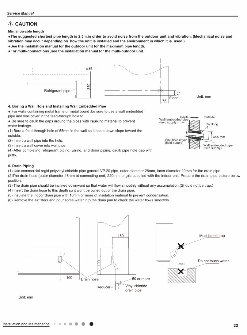
Min.allowable length●The suggested shortest pipe length is 2.5m,in order to avoid noise from the outdoor unit and vibration. (Mechanical noise and vibration may occur depending on how the unit is installed and the environment in which it is used.)●See the installation manual for the outdoor unit for the maximum pipe length.●For multi-connections ,see the installation manual for the multi-outdoor unit.
Unit: mm
4. Boring a Wall Hole and Installing Wall Embedded Pipe● For walls containing metal frame or metal board ,be sure to use a wall embeddedpipe and wall cover in the feed-through hole to● Be sure to caulk the gaps around the pipes with caulking material to preventwater leakage.(1) Bore a feed-through hole of 55mm in the wall so it has a down slope toward theoutside.(2) Insert a wall pipe into the hole.(3) Insert a wall cover into wall pipe .(4) After completing refrigerant piping, wiring, and drain piping, caulk pipe hole gap with putty.
5. Drain Piping(1) Use commercial regid polyvinyl chloride pipe general VP 20 pipe, outer diameter 26mm, inner diameter 20mm for the drain pipe.(2)The drain hose (outer diameter 18mm at connecting end, 220mm long)is supplied with the indoor unit. Prepare the drain pipe picture below position.(3) The drain pipe should be inclined downward so that water will flow smoothly without any accumulation.(Should not be trap.)(4) Insert the drain hose to this depth so it wont be pulled out of the drain pipe.(5) Insulate the indoor drain pipe with 10mm or more of insulation material to prevent condensation.(6) Remove the air filters and pour some water into the drain pan to check the water flows smoothly.
Inside Outside
CaulkingWall embedded pipe (field supply)
Wall hole cover(field supply)
Wall embedded pipe (field supply)
Φ55 mm
100 Drain hose
100
150
Vinyl chloridedrain pipe
50 or more
Reducer
Must be no trap
Do not touch water
350
wall
Refrigerant pipe
45
75Floor
Unit: mm
CAUTION
24 Installation and Maintenance
Service Manual
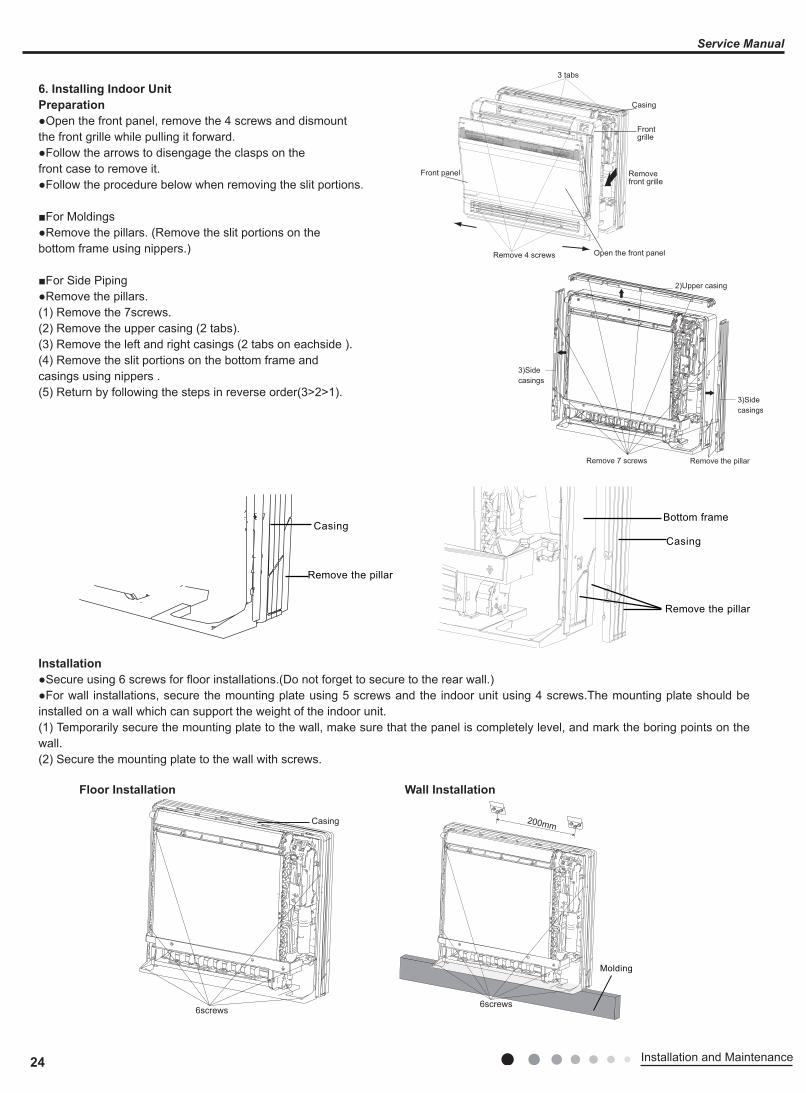
6. Installing Indoor UnitPreparation●Open the front panel, remove the 4 screws and dismountthe front grille while pulling it forward.●Follow the arrows to disengage the clasps on thefront case to remove it.●Follow the procedure below when removing the slit portions.
■For Moldings●Remove the pillars. (Remove the slit portions on thebottom frame using nippers.)
■For Side Piping●Remove the pillars.(1) Remove the 7screws.(2) Remove the upper casing (2 tabs).(3) Remove the left and right casings (2 tabs on eachside ).(4) Remove the slit portions on the bottom frame andcasings using nippers .(5) Return by following the steps in reverse order(3>2>1).
Installation●Secure using 6 screws for floor installations.(Do not forget to secure to the rear wall.)●For wall installations, secure the mounting plate using 5 screws and the indoor unit using 4 screws.The mounting plate should be installed on a wall which can support the weight of the indoor unit.(1) Temporarily secure the mounting plate to the wall, make sure that the panel is completely level, and mark the boring points on the wall.(2) Secure the mounting plate to the wall with screws.
Front panel
Open the front panel
Removefront grille
Casing
Frontgrille
Remove 4 screws
3 tabs
3)Sidecasings
2)Upper casing
3)Sidecasings
Remove the pillarRemove 7 screws
Casing
Remove the pillar
Casing
Remove the pillar
Bottom frame
6screws
Casing
6screws
Molding
200mm
Floor Installation Wall Installation
25Installation and Maintenance
Service Manual
(3) Once refrigerant piping and drain piping connections are complete, fill in the gap of the through hole with putty. A gap can lead to condensation on the refrigerant pipe, and drain pipe, and the entry of insects into the pipes.(4) Attach the front panel and front grille in their original positions once all connections are complete.
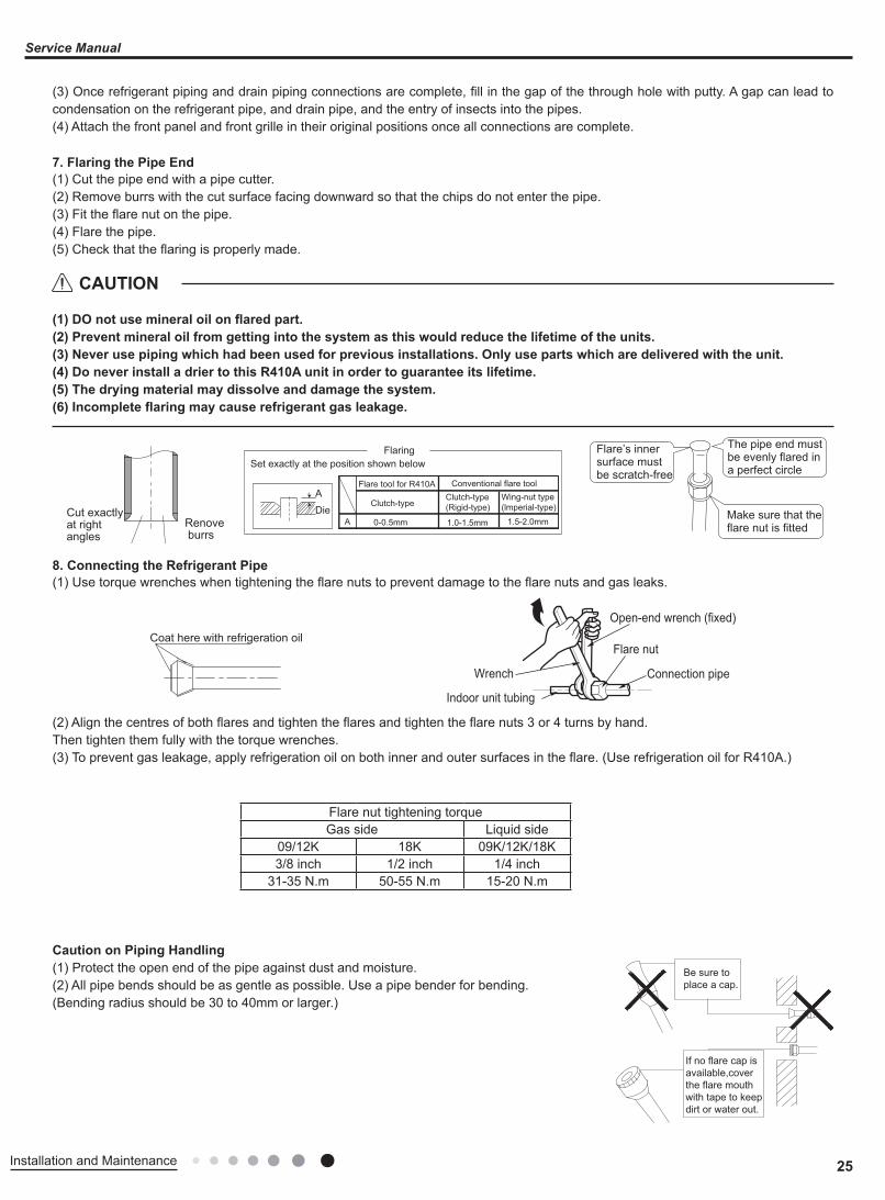
7. Flaring the Pipe End(1) Cut the pipe end with a pipe cutter.(2) Remove burrs with the cut surface facing downward so that the chips do not enter the pipe.(3) Fit the flare nut on the pipe.(4) Flare the pipe.(5) Check that the flaring is properly made.
(1) DO not use mineral oil on flared part.(2) Prevent mineral oil from getting into the system as this would reduce the lifetime of the units.(3) Never use piping which had been used for previous installations. Only use parts which are delivered with the unit.(4) Do never install a drier to this R410A unit in order to guarantee its lifetime.(5) The drying material may dissolve and damage the system.(6) Incomplete flaring may cause refrigerant gas leakage.
8. Connecting the Refrigerant Pipe(1) Use torque wrenches when tightening the flare nuts to prevent damage to the flare nuts and gas leaks.
(2) Align the centres of both flares and tighten the flares and tighten the flare nuts 3 or 4 turns by hand.Then tighten them fully with the torque wrenches.(3) To prevent gas leakage, apply refrigeration oil on both inner and outer surfaces in the flare. (Use refrigeration oil for R410A.)
Caution on Piping Handling(1) Protect the open end of the pipe against dust and moisture.(2) All pipe bends should be as gentle as possible. Use a pipe bender for bending.(Bending radius should be 30 to 40mm or larger.)
Make sure that theflare nut is fitted
The pipe end mustbe evenly flared in a perfect circle
Flare’s inner surface mustbe scratch-free
Cut exactlyat rightangles
Renoveburrs
FlaringSet exactly at the position shown below
A
DieA 0-0.5mm 1.0-1.5mm 1.5-2.0mm
Flare tool for R410A
Clutch-typeClutch-type(Rigid-type)
Wing-nut type(lmperial-type)
Conventional flare tool
Wrench
Indoor unit tubing
Open-end wrench (fixed)
Connection pipe
Flare nutCoat here with refrigeration oil
Be sure toplace a cap.
If no flare cap isavailable,cover the flare mouth with tape to keepdirt or water out.
Flare nut tightening torqueGas side Liquid side
09/12K 18K 09K/12K/18K3/8 inch 1/2 inch 1/4 inch
31-35 N.m 50-55 N.m 15-20 N.m
CAUTION
26 Installation and Maintenance
Service Manual
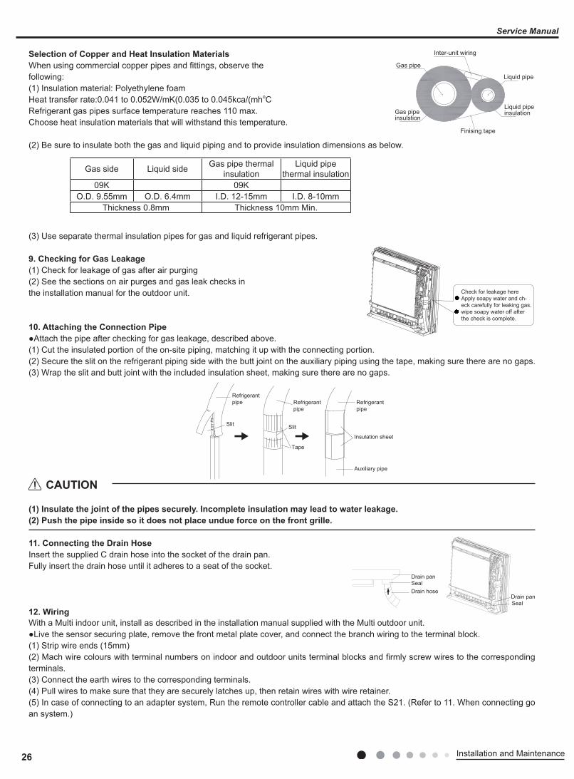
Selection of Copper and Heat Insulation MaterialsWhen using commercial copper pipes and fittings, observe thefollowing:(1) Insulation material: Polyethylene foamHeat transfer rate:0.041 to 0.052W/mK(0.035 to 0.045kca/(mhoCRefrigerant gas pipes surface temperature reaches 110 max.Choose heat insulation materials that will withstand this temperature.
(2) Be sure to insulate both the gas and liquid piping and to provide insulation dimensions as below.
(3) Use separate thermal insulation pipes for gas and liquid refrigerant pipes.
9. Checking for Gas Leakage(1) Check for leakage of gas after air purging(2) See the sections on air purges and gas leak checks inthe installation manual for the outdoor unit.
10. Attaching the Connection Pipe●Attach the pipe after checking for gas leakage, described above.(1) Cut the insulated portion of the on-site piping, matching it up with the connecting portion.(2) Secure the slit on the refrigerant piping side with the butt joint on the auxiliary piping using the tape, making sure there are no gaps.(3) Wrap the slit and butt joint with the included insulation sheet, making sure there are no gaps.
(1) Insulate the joint of the pipes securely. Incomplete insulation may lead to water leakage.(2) Push the pipe inside so it does not place undue force on the front grille.
11. Connecting the Drain HoseInsert the supplied C drain hose into the socket of the drain pan.Fully insert the drain hose until it adheres to a seat of the socket.
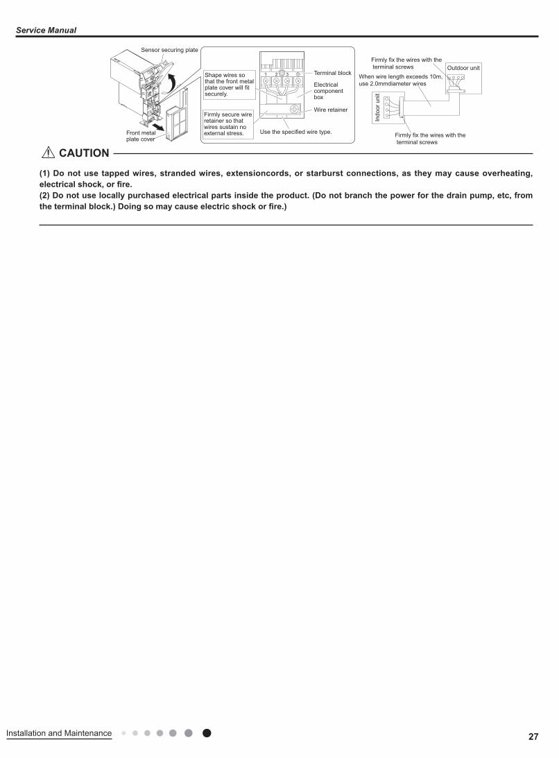
12. WiringWith a Multi indoor unit, install as described in the installation manual supplied with the Multi outdoor unit.●Live the sensor securing plate, remove the front metal plate cover, and connect the branch wiring to the terminal block.(1) Strip wire ends (15mm)(2) Mach wire colours with terminal numbers on indoor and outdoor units terminal blocks and firmly screw wires to the corresponding terminals.(3) Connect the earth wires to the corresponding terminals.(4) Pull wires to make sure that they are securely latches up, then retain wires with wire retainer.(5) In case of connecting to an adapter system, Run the remote controller cable and attach the S21. (Refer to 11. When connecting go an system.)
Gas pipe
Gas pipeinsulstion
Finising tape
Inter-unit wiring
Liquid pipe
Liquid pipeinsulation
Gas side Liquid side Gas pipe thermal insulation
Liquid pipethermal insulation
09K 09KO.D. 9.55mm O.D. 6.4mm I.D. 12-15mm I.D. 8-10mm
Thickness 0.8mm Thickness 10mm Min.
Check for leakage hereApply soapy water and ch-eck carefully for leaking gas.wipe soapy water off afterthe check is complete.
Refrigerantpipe Refrigerant
pipeRefrigerantpipe
Slit Slit
Tape
Auxiliary pipe
Insulation sheet
Drain panSeal
Drain panSealDrain hose
CAUTION
27Installation and Maintenance
Service Manual
(1) Do not use tapped wires, stranded wires, extensioncords, or starburst connections, as they may cause overheating, electrical shock, or fire.(2) Do not use locally purchased electrical parts inside the product. (Do not branch the power for the drain pump, etc, from the terminal block.) Doing so may cause electric shock or fire.)
Outdoor unit
Indo
or u
nit
Firmly fix the wires with the terminal screws
Firmly fix the wires with the terminal screws
When wire length exceeds 10m,use 2.0mmdiameter wires
1 2 3 Terminal block
Electrical componentbox
Wire retainer
Use the specified wire type.
Shape wires so that the front metal plate cover will fit securely.
Firmly secure wire retainer so that wires sustain no external stress.Front metal
plate cover
Sensor securing plate
CAUTION
28 Installation and Maintenance
Service Manual
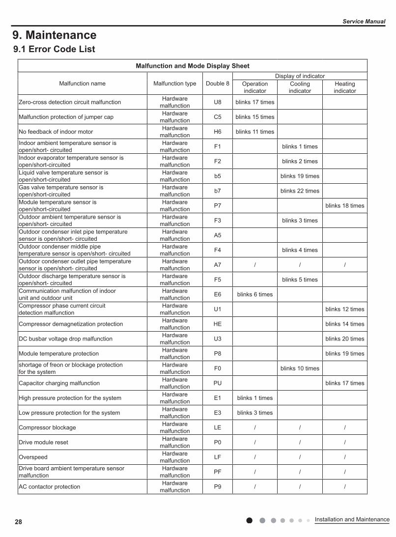
9. Maintenance9.1 Error Code List
Malfunction and Mode Display Sheet
Malfunction name Malfunction type Double 8Display of indicator
Operation indicator
Cooling indicator
Heating indicator
Zero-cross detection circuit malfunction Hardware malfunction U8 blinks 17 times
Malfunction protection of jumper cap Hardware malfunction C5 blinks 15 times
No feedback of indoor motor Hardware malfunction H6 blinks 11 times
Indoor ambient temperature sensor is open/short- circuited
Hardware malfunction F1 blinks 1 times
Indoor evaporator temperature sensor is open/short-circuited
Hardware malfunction F2 blinks 2 times
Liquid valve temperature sensor is open/short-circuited
Hardware malfunction b5 blinks 19 times
Gas valve temperature sensor is open/short-circuited
Hardware malfunction b7 blinks 22 times
Module temperature sensor is open/short-circuited
Hardware malfunction P7 blinks 18 times
Outdoor ambient temperature sensor is open/short- circuited
Hardware malfunction F3 blinks 3 times
Outdoor condenser inlet pipe temperature sensor is open/short- circuited
Hardware malfunction A5
Outdoor condenser middle pipe temperature sensor is open/short- circuited
Hardware malfunction F4 blinks 4 times
Outdoor condenser outlet pipe temperature sensor is open/short- circuited
Hardware malfunction A7 / / /
Outdoor discharge temperature sensor is open/short- circuited
Hardware malfunction F5 blinks 5 times
Communication malfunction of indoor unit and outdoor unit
Hardware malfunction E6 blinks 6 times
Compressor phase current circuit detection malfunction
Hardware malfunction U1 blinks 12 times
Compressor demagnetization protection Hardware malfunction HE blinks 14 times
DC busbar voltage drop malfunction Hardware malfunction U3 blinks 20 times
Module temperature protection Hardware malfunction P8 blinks 19 times
shortage of freon or blockage protection for the system
Hardware malfunction F0 blinks 10 times
Capacitor charging malfunction Hardware malfunction PU blinks 17 times
High pressure protection for the system Hardware malfunction E1 blinks 1 times
Low pressure protection for the system Hardware malfunction E3 blinks 3 times
Compressor blockage Hardware malfunction LE / / /
Drive module reset Hardware malfunction P0 / / /
Overspeed Hardware malfunction LF / / /
Drive board ambient temperature sensor malfunction
Hardware malfunction PF / / /
AC contactor protection Hardware malfunction P9 / / /
29Installation and Maintenance
Service Manual
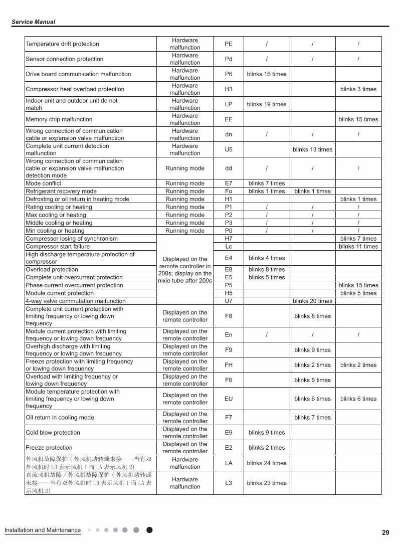
Malfunction and Mode Display Sheet
Malfunction name Malfunction type Double 8Display of indicator
Operation indicator
Cooling indicator
Heating indicator
Zero-cross detection circuit malfunction Hardware malfunction U8 blinks 17 times
Malfunction protection of jumper cap Hardware malfunction C5 blinks 15 times
No feedback of indoor motor Hardware malfunction H6 blinks 11 times
Indoor ambient temperature sensor is open/short- circuited
Hardware malfunction F1 blinks 1 times
Indoor evaporator temperature sensor is open/short-circuited
Hardware malfunction F2 blinks 2 times
Liquid valve temperature sensor is open/short-circuited
Hardware malfunction b5 blinks 19 times
Gas valve temperature sensor is open/short-circuited
Hardware malfunction b7 blinks 22 times
Module temperature sensor is open/short-circuited
Hardware malfunction P7 blinks 18 times
Outdoor ambient temperature sensor is open/short- circuited
Hardware malfunction F3 blinks 3 times
Outdoor condenser inlet pipe temperature sensor is open/short- circuited
Hardware malfunction A5
Outdoor condenser middle pipe temperature sensor is open/short- circuited
Hardware malfunction F4 blinks 4 times
Outdoor condenser outlet pipe temperature sensor is open/short- circuited
Hardware malfunction A7 / / /
Outdoor discharge temperature sensor is open/short- circuited
Hardware malfunction F5 blinks 5 times
Communication malfunction of indoor unit and outdoor unit
Hardware malfunction E6 blinks 6 times
Compressor phase current circuit detection malfunction
Hardware malfunction U1 blinks 12 times
Compressor demagnetization protection Hardware malfunction HE blinks 14 times
DC busbar voltage drop malfunction Hardware malfunction U3 blinks 20 times
Module temperature protection Hardware malfunction P8 blinks 19 times
shortage of freon or blockage protection for the system
Hardware malfunction F0 blinks 10 times
Capacitor charging malfunction Hardware malfunction PU blinks 17 times
High pressure protection for the system Hardware malfunction E1 blinks 1 times
Low pressure protection for the system Hardware malfunction E3 blinks 3 times
Compressor blockage Hardware malfunction LE / / /
Drive module reset Hardware malfunction P0 / / /
Overspeed Hardware malfunction LF / / /
Drive board ambient temperature sensor malfunction
Hardware malfunction PF / / /
AC contactor protection Hardware malfunction P9 / / /
Temperature drift protection Hardware malfunction PE / / /
Sensor connection protection Hardware malfunction Pd / / /
Drive board communication malfunction Hardware malfunction P6 blinks 16 times
Compressor heat overload protection Hardware malfunction H3 blinks 3 times
Indoor unit and outdoor unit do not match
Hardware malfunction LP blinks 19 times
Memory chip malfunction Hardware malfunction EE blinks 15 times
Wrong connection of communication cable or expansion valve malfunction
Hardware malfunction dn / / /
Complete unit current detection malfunction
Hardware malfunction U5 blinks 13 times
Wrong connection of communication cable or expansion valve malfunction detection mode
Running mode dd / / /
Mode conflict Running mode E7 blinks 7 timesRefrigerant recovery mode Running mode Fo blinks 1 times blinks 1 timesDefrosting or oil return in heating mode Running mode H1 blinks 1 timesRating cooling or heating Running mode P1 / / /Max cooling or heating Running mode P2 / / /Middle cooling or heating Running mode P3 / / /Min cooling or heating Running mode P0 / / /Compressor losing of synchronism
Displayed on the remote controller in 200s; display on the nixie tube after 200s
H7 blinks 7 timesCompressor start failure Lc blinks 11 timesHigh discharge temperature protection of compressor E4 blinks 4 times
Overload protection E8 blinks 8 timesComplete unit overcurrent protection E5 blinks 5 timesPhase current overcurrent protection P5 blinks 15 timesModule current protection H5 blinks 5 times4-way valve commutation malfunction U7 blinks 20 timesComplete unit current protection with limiting frequency or lowing down frequency
Displayed on the remote controller F8 blinks 8 times
Module current protection with limiting frequency or lowing down frequency
Displayed on the remote controller En / / /
Overhigh discharge with limiting frequency or lowing down frequency
Displayed on the remote controller F9 blinks 9 times
Freeze protection with limiting frequency or lowing down frequency
Displayed on the remote controller FH blinks 2 times blinks 2 times
Overload with limiting frequency or lowing down frequency
Displayed on the remote controller F6 blinks 6 times
Module temperature protection with limiting frequency or lowing down frequency
Displayed on the remote controller EU blinks 6 times blinks 6 times
Oil return in cooling mode Displayed on the remote controller F7 blinks 7 times
Cold blow protection Displayed on the remote controller E9 blinks 9 times
Freeze protection Displayed on the remote controller E2 blinks 2 times
外风机故障保护 (外风机堵转或未接——当有双
外风机时 L3 表示风机 1而 LA 表示风机 2)
Hardware malfunction LA blinks 24 times
直流风机故障 /外风机故障保护 (外风机堵转或
未接——当有双外风机时 L3 表示风机 1而 LA 表
示风机 2)
Hardware malfunction L3 blinks 23 times
30 Installation and Maintenance
Service Manual
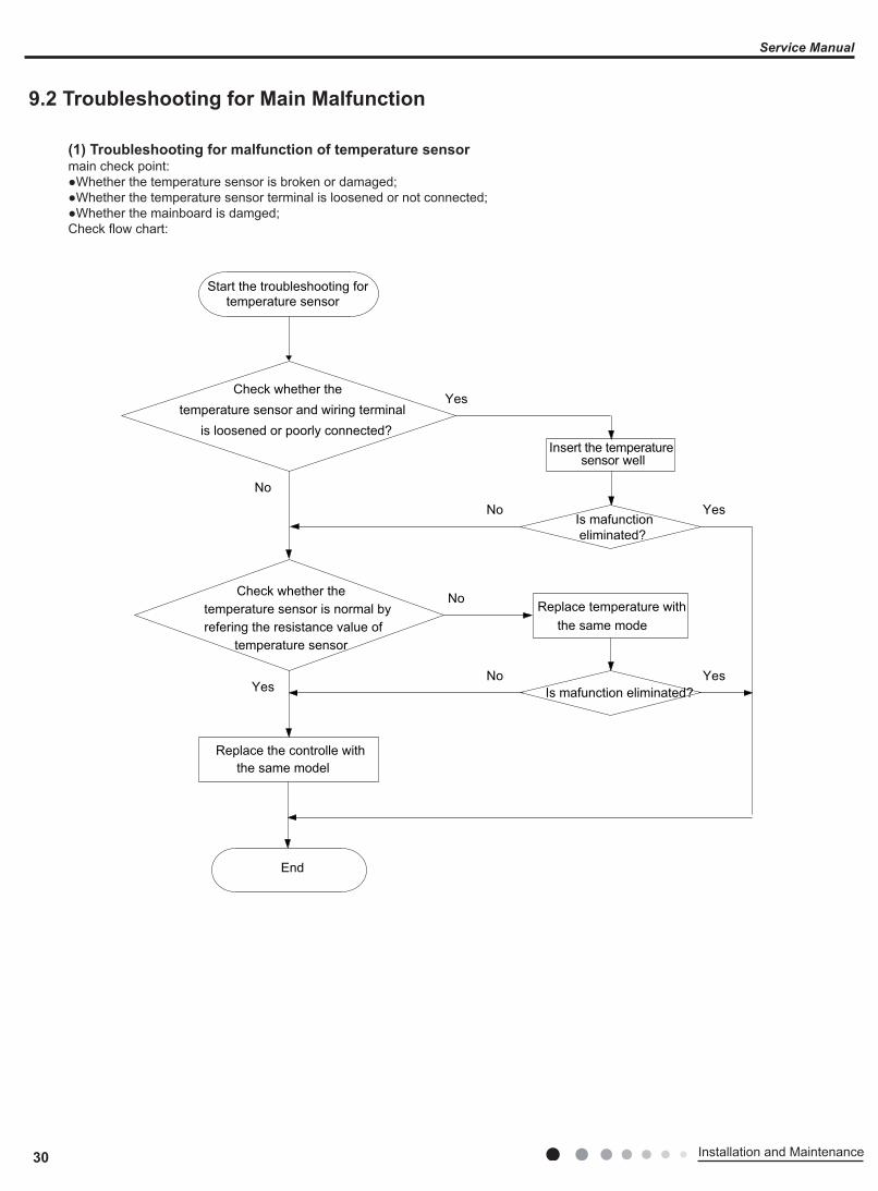
9.2 Troubleshooting for Main Malfunction
(1) Troubleshooting for malfunction of temperature sensormain check point:●Whether the temperature sensor is broken or damaged;●Whether the temperature sensor terminal is loosened or not connected;●Whether the mainboard is damged;Check flow chart:
Start the troubleshooting fortemperature sensor
Check whether the temperature sensor and wiring terminal is loosened or poorly connected?
Insert the temperaturesensor well
Is mafunction eliminated?
Is mafunction eliminated?
Replace temperature withthe same mode
Check whether thetemperature sensor is normal by refering the resistance value of
temperature sensor
Replace the controlle withthe same model
End
No
No
No
No
YesYes
Yes
Yes
31Installation and Maintenance
Service Manual
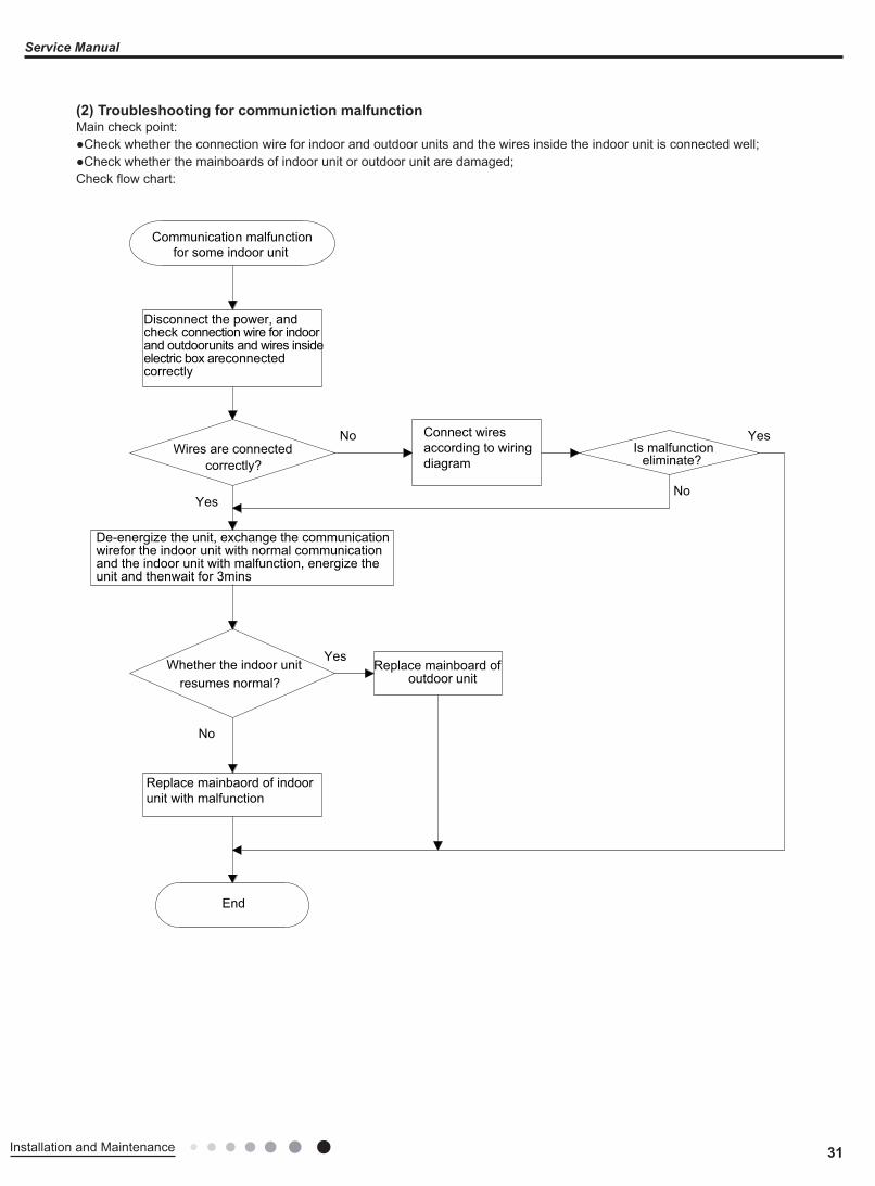
(2) Troubleshooting for communiction malfunctionMain check point:●Check whether the connection wire for indoor and outdoor units and the wires inside the indoor unit is connected well;●Check whether the mainboards of indoor unit or outdoor unit are damaged;Check flow chart:
Replace mainboard ofoutdoor unit
Wires are connectedcorrectly?
Is malfunctioneliminate?
Communication malfunctionfor some indoor unit
End
No
No
No
Yes
Yes
Yes
Whether the indoor unitresumes normal?
Disconnect the power, and check connection wire for indoor and outdoorunits and wires inside electric box areconnected correctly
De-energize the unit, exchange the communication wirefor the indoor unit with normal communication and the indoor unit with malfunction, energize the unit and thenwait for 3mins
Replace mainbaord of indoor unit with malfunction
Connect wires according to wiring diagram

32 Installation and Maintenance
Service Manual
Is malfunction eliminated?
Is malfunction eliminated?
Is malfunction eliminated?
Is malfunction eliminated?
Replace connection wires
Wires are connected correctly?
Wires are connected correctly?
Whether connectionwires are damaged?
Whether there'spower input?
Replace mainboard ofoutdoor unit
Communication isresumed ?
End
All indoor units alarms communication malfunction
Check whether the neutral wirefor mainboard of outdoor unit haspower input
Connect wire connectly according to wiring diagram
Connect wire connectly according to wiring diagram
Disconnect the power, and check whether theconnection wires between mainboard of outdoorunit and filter palte are connected correctly byreferring to wiring diagram
Disconnect the power, and check connection wire for indoor and outdoorunits and wires inside electric box areconnected correctly
Replace filter plate ofoutdoor unit
Replace filter plate of outdoor unit
No
No
No
Yes
Yes
No
No
Yes
No
No
No
Yes
No
Yes
Yes
Yes
Yes
Yes
33Installation and Maintenance
Service Manual
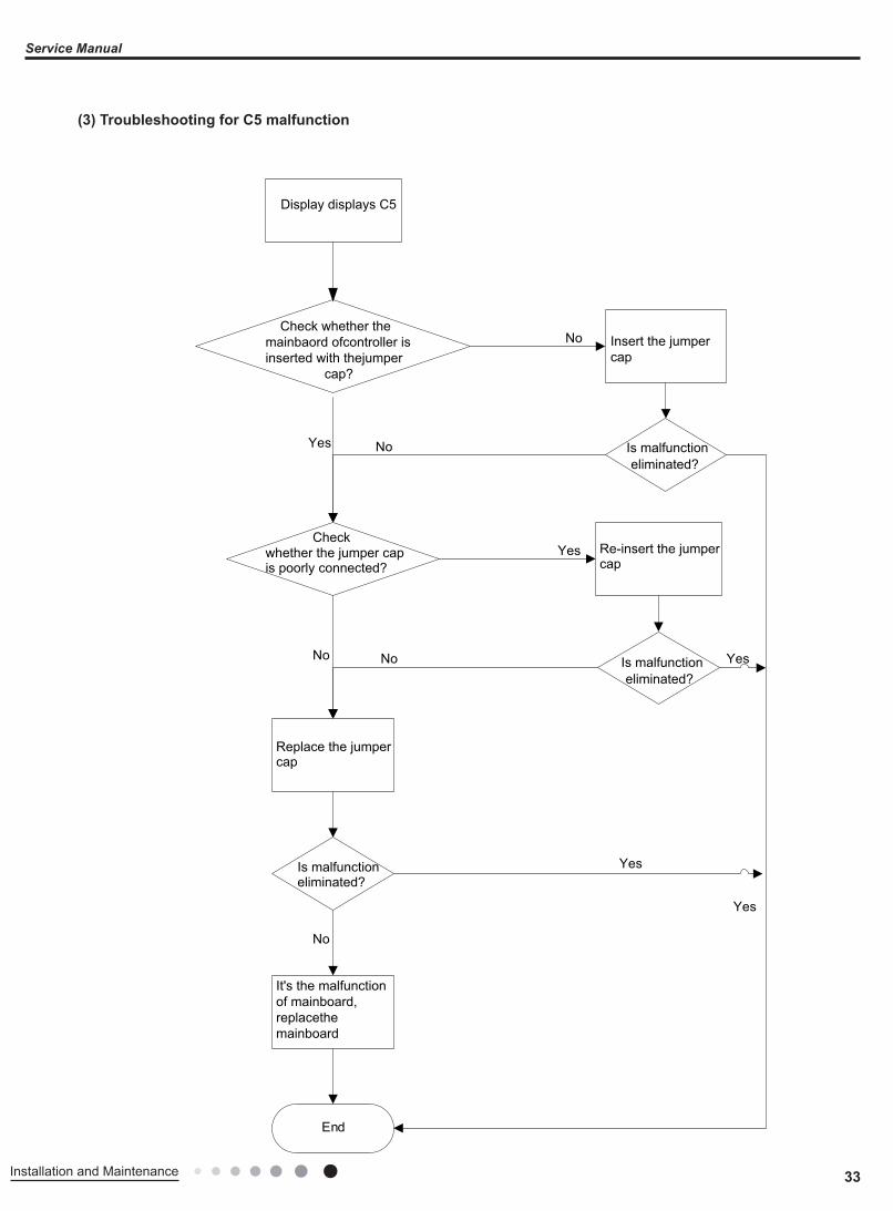
(3) Troubleshooting for C5 malfunction
No
Yes
No
Yes
End
Yes
No
No Yes
No
Yes
Display displays C5
whether the jumper cap is poorly connected?
Insert the jumper cap
Is malfunction eliminated?
Re-insert the jumpercap
Is malfunction eliminated?
Replace the jumpercap
Is malfunction eliminated?
Check whether the mainbaord ofcontroller is inserted with thejumper cap?
It's the malfunction of mainboard, replacethe mainboard
Check

34 Installation and Maintenance
Service Manual
(4) Troubleshooting for H6 malfunction
Insert the motor terminal tightly
Is mafunctioneliminated?
Is mafunctioneliminated?
Is mafunctioneliminated?
Re-assemble bladeand motor correctly
Whethermotor can be started
up
Replace motor
Replace controller
End
No
No
No
No
NoNo
No
Yes Yes
Yes
Yes
Yes
YesYes
Yes
Yes
Yes
Energize the unit and turn on the unit. Afterthe horizontal louver opens for 1 min, measurewhether the input DC voltage VDC (red wire) of motor is300s, whether the DC voltageVCC (white wire0 is 15V and whether the outputVSP (yellow wire) is more than 1.1V. The earthingwire is black wire;
Whether the voltageon motor feedbackterminal (blue wire)is more than 1.1V
Pull bladewith hand to seewhetherit can rotatesmoothly
Check whether theterminal of DC motor isconnected tightly
Start the troubleshootingfor H6 malfunction

35Installation and Maintenance
Service Manual
Possible Causes Discriminating Method (Air conditioner Status) Troubleshooting Set temperature is improper Observe the set temperature on remote controller Adjust the set temperatureRotation speed of the IDU fan motor is set too low Small wind blow Set the fan speed at high or medium
Filter of indoor unit is blocked Check the filter to see it's blocked Clean the filter
Installation position for indoor unit and outdoor unit is improper
Check whether the installation postion is proper according to installation requirement for air conditioner
Adjust the installation position, and install the rainproof and sunproof for outdoor unit
Refrigerant is leaking
Discharged air temperature during cooling is higher than normal discharged wind temperature; Discharged air temperature during heating is lower than normal discharged wind temperature; Unit's pressure is much lower than regulated range
Find out the leakage causes and deal with it. Add refrigerant.
Malfunction of 4-way valve Blow cold wind during heating Replace the 4-way valve
Malfunction of capillary
Discharged air temperature during cooling is higher than normal discharged wind temperature; Discharged air temperature during heating is lower than normal discharged wind temperature; Unit't pressure is much lower than regulated range. If refrigerant isn’t leaking, part of capillary is blocked
Replace the capillary
Flow volume of valve is insufficient
The pressure of valves is much lower than that stated in the specification Open the valve completely
Malfunction of horizontal louver Horizontal louver can’t swing Refer to point 3 of maintenance method for details
Malfunction of the IDU fan motor The IDU fan motor can’t operate Refer to troubleshooting for H6 for maintenance method in details
Malfunction of the ODU fan motor The ODU fan motor can't operate Refer to point 4 of maintenance method for details
Malfunction of compressor Compressor can't operate Refer to point 5 of maintenance method for details
9.3 Maintenance Method for Normal Malfunction1. Air Conditioner Can't be Started Up
2. Poor Cooling (Heating) for Air Conditioner
3. Horizontal Louver Can't Swing
Possible Causes Discriminating Method (Air conditioner Status) Troubleshooting
No power supply, or poor connection for power plug
After energization, operation indicator isn’t bright and the buzzer can't give out sound
Confirm whether it's due to power failure. If yes, wait for power recovery. If not, check power supply circuit and make sure the power plug is connected well.
Wrong wire connection between indoor unit and outdoor unit, or poor connection for wiring terminals
Under normal power supply circumstances, operation indicator isn't bright after energization
Check the circuit according to circuit diagram and connect wires correctly. Make sure all wiring terminals are connected firmly
Electric leakage for air conditionerAfter energization, room circuit breaker trips off at once
Make sure the air conditioner is grounded reliablyMake sure wires of air conditioner is connected correctlyCheck the wiring inside air conditioner. Check whether the insulation layer of power cord is damaged; if yes, place the power cord.
Model selection for air switch is improper After energization, air switch trips off Select proper air switch
Malfunction of remote controller After energization, operation indicator is bright, while no display on remote controller or buttons have no action.
Replace batteries for remote controllerRepair or replace remote controller
Possible Causes Discriminating Method (Air conditioner Status) Troubleshooting
Wrong wire connection, or poor connection
Check the wiring status according to circuit diagram
Connect wires according to wiring diagram to make sure all wiring terminals are connected firmly
Stepping motor is damaged Stepping motor can't operate Repair or replace stepping motor
Main board is damaged Others are all normal, while horizontal louver can't operate Replace the main board with the same model

36 Installation and Maintenance
Service Manual
7. Abnormal Sound and Vibration
Possible causes Discriminating method (air conditioner status) Troubleshooting When turn on or turn off the unit, the panel and other parts will expand and there's abnormal sound
There's the sound of "PAPA" Normal phenomenon. Abnormal sound will disappear after a few minutes.
When turn on or turn off the unit, there's abnormal sound due to flow of refrigerant inside air conditioner
Water-running sound can be heard Normal phenomenon. Abnormal sound will disappear after a few minutes.
Foreign objects inside the indoor unit or there're parts touching together inside the indoor unit
There's abnormal sound fro indoor unitRemove foreign objects. Adjust all parts' position of indoor unit, tighten screws and stick damping plaster between connected parts
Foreign objects inside the outdoor unit or there're parts touching together inside the outdoor unit
There's abnormal sound fro outdoor unitRemove foreign objects. Adjust all parts' position of outdoor unit, tighten screws and stick damping plaster between connected parts
Short circuit inside the magnetic coil
During heating, the way valve has abnormal electromagnetic sound Replace magnetic coil
Abnormal shake of compressor Outdoor unit gives out abnormal sound Adjust the support foot mat of compressor, tighten the bolts
Abnormal sound inside the compressor Abnormal sound inside the compressor
If add too much refrigerant during maintenance, please reduce refrigerant properly. Replace compressor for other circumstances.
6. Air Conditioner is Leaking Possible causes Discriminating method (air conditioner status) Troubleshooting
Drain pipe is blocked Water leaking from indoor unit Eliminate the foreign objects inside the drain pipe
Drain pipe is broken Water leaking from drain pipe Replace drain pipe
Wrapping is not tight Water leaking from the pipe connection place of indoor unit Wrap it again and bundle it tightly
5. Compressor Can't Operate
Possible causes Discriminating method (air conditioner status) Troubleshooting
Wrong wire connection, or poor connection
Check the wiring status according to circuit diagram
Connect wires according to wiring diagram to make sure all wiring terminals are connected firmly
Capacity of compressor is damaged
Measure the capacity of fan capacitor with an universal meter and find that the capacity is out of the deviation range indicated on the nameplate of fan capacitor.
Replace the compressor capacitor
Power voltage is a little low or high
Use universal meter to measure the power supply voltage. The voltage is a little high or low Suggest to equip with voltage regulator
Coil of compressor is burnt out Use universal meter to measure the resistance between compressor terminals and it's 0 Repair or replace compressor
Cylinder of compressor is blocked Compressor can't operate Repair or replace compressor
4. ODU Fan Motor Can't OperatePossible causes Discriminating method (air conditioner status) Troubleshooting
Wrong wire connection, or poor connection
Check the wiring status according to circuit diagram
Connect wires according to wiring diagram to make sure all wiring terminals are connected firmly
Capacity of the ODU fan motor is damaged
Measure the capacity of fan capacitor with an universal meter and find that the capacity is out of the deviation range indicated on the nameplate of fan capacitor.
Replace the capacity of fan
Power voltage is a little low or high
Use universal meter to measure the power supply voltage. The voltage is a little high or low Suggest to equip with voltage regulator
Motor of outdoor unit is damagedWhen unit is on, cooling/heating performance is bad and ODU compressor generates a lot of noise and heat.
Change compressor oil and refrigerant. If no better, replace the compressor with a new one

37Installation and Maintenance
Service Manual
10. Exploded View and Parts List10.1 Indoor Unit
1
2
3
4
78
14
13
12
18
20
109
222324
25
19
5
26
2827
6
11
17
21
15 16
The component is only for reference;please refer to the actual product.
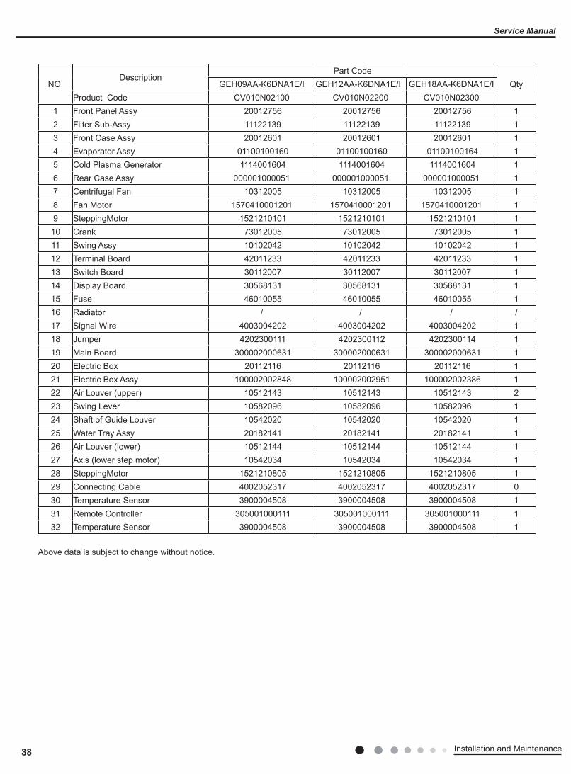
38 Installation and Maintenance
Service Manual
NO.Description
Part CodeQtyGEH09AA-K6DNA1E/I GEH12AA-K6DNA1E/I GEH18AA-K6DNA1E/I
Product Code CV010N02100 CV010N02200 CV010N023001 Front Panel Assy 20012756 20012756 20012756 12 Filter Sub-Assy 11122139 11122139 11122139 13 Front Case Assy 20012601 20012601 20012601 14 Evaporator Assy 01100100160 01100100160 01100100164 15 Cold Plasma Generator 1114001604 1114001604 1114001604 16 Rear Case Assy 000001000051 000001000051 000001000051 17 Centrifugal Fan 10312005 10312005 10312005 18 Fan Motor 1570410001201 1570410001201 1570410001201 19 SteppingMotor 1521210101 1521210101 1521210101 1
10 Crank 73012005 73012005 73012005 111 Swing Assy 10102042 10102042 10102042 112 Terminal Board 42011233 42011233 42011233 113 Switch Board 30112007 30112007 30112007 114 Display Board 30568131 30568131 30568131 115 Fuse 46010055 46010055 46010055 116 Radiator / / / /17 Signal Wire 4003004202 4003004202 4003004202 118 Jumper 4202300111 4202300112 4202300114 119 Main Board 300002000631 300002000631 300002000631 120 Electric Box 20112116 20112116 20112116 121 Electric Box Assy 100002002848 100002002951 100002002386 122 Air Louver (upper) 10512143 10512143 10512143 223 Swing Lever 10582096 10582096 10582096 124 Shaft of Guide Louver 10542020 10542020 10542020 125 Water Tray Assy 20182141 20182141 20182141 126 Air Louver (lower) 10512144 10512144 10512144 127 Axis (lower step motor) 10542034 10542034 10542034 128 SteppingMotor 1521210805 1521210805 1521210805 129 Connecting Cable 4002052317 4002052317 4002052317 030 Temperature Sensor 3900004508 3900004508 3900004508 131 Remote Controller 305001000111 305001000111 305001000111 132 Temperature Sensor 3900004508 3900004508 3900004508 1
Above data is subject to change without notice.
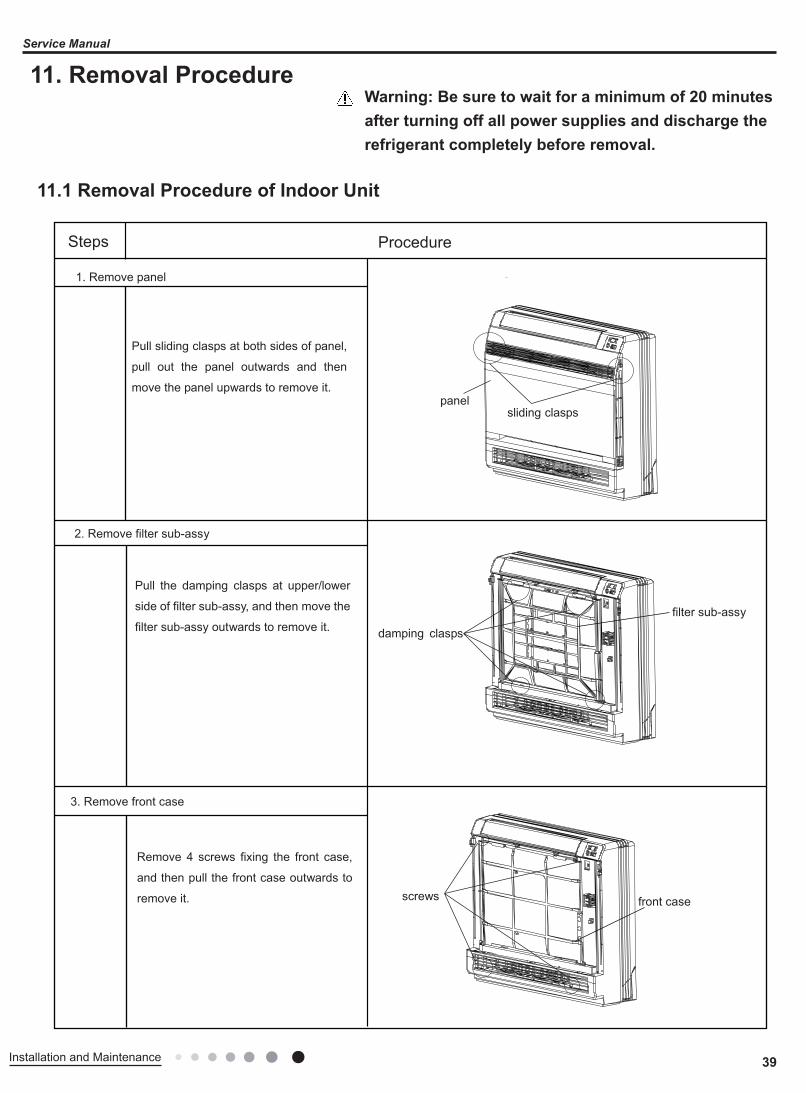
39Installation and Maintenance
Service Manual
11. Removal Procedure
11.1 Removal Procedure of Indoor Unit
Warning: Be sure to wait for a minimum of 20 minutes after turning off all power supplies and discharge the refrigerant completely before removal.
Steps Procedure
1. Remove panel
Pull sliding clasps at both sides of panel,
pull out the panel outwards and then
move the panel upwards to remove it.
2. Remove filter sub-assy
Pull the damping clasps at upper/lower
side of filter sub-assy, and then move the
filter sub-assy outwards to remove it.
3. Remove front case
Remove 4 screws fixing the front case,
and then pull the front case outwards to
remove it.
panel sliding clasps
damping clasps
filter sub-assy
screws front case
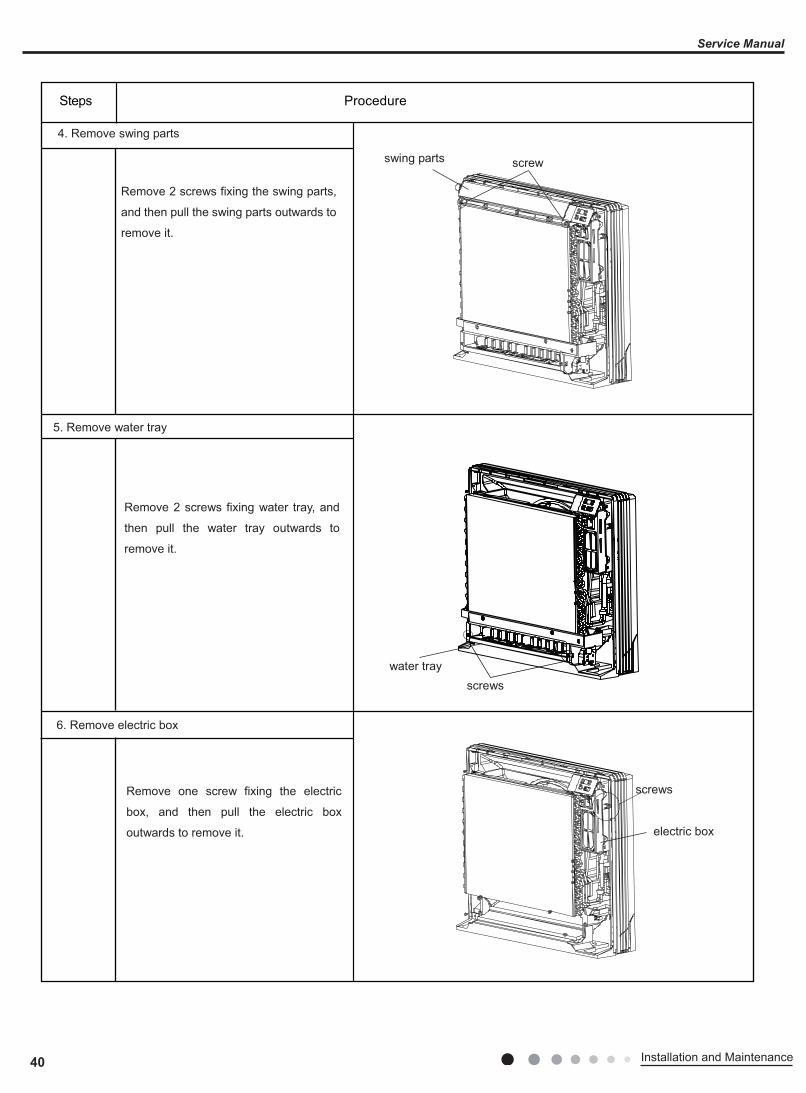
40 Installation and Maintenance
Service Manual
4. Remove swing parts
Remove 2 screws fixing the swing parts,
and then pull the swing parts outwards to
remove it.
5. Remove water tray
Remove 2 screws fixing water tray, and
then pull the water tray outwards to
remove it.
6. Remove electric box
Remove one screw fixing the electric
box, and then pull the electric box
outwards to remove it.
swing parts screw
water trayscrews
screws
electric box
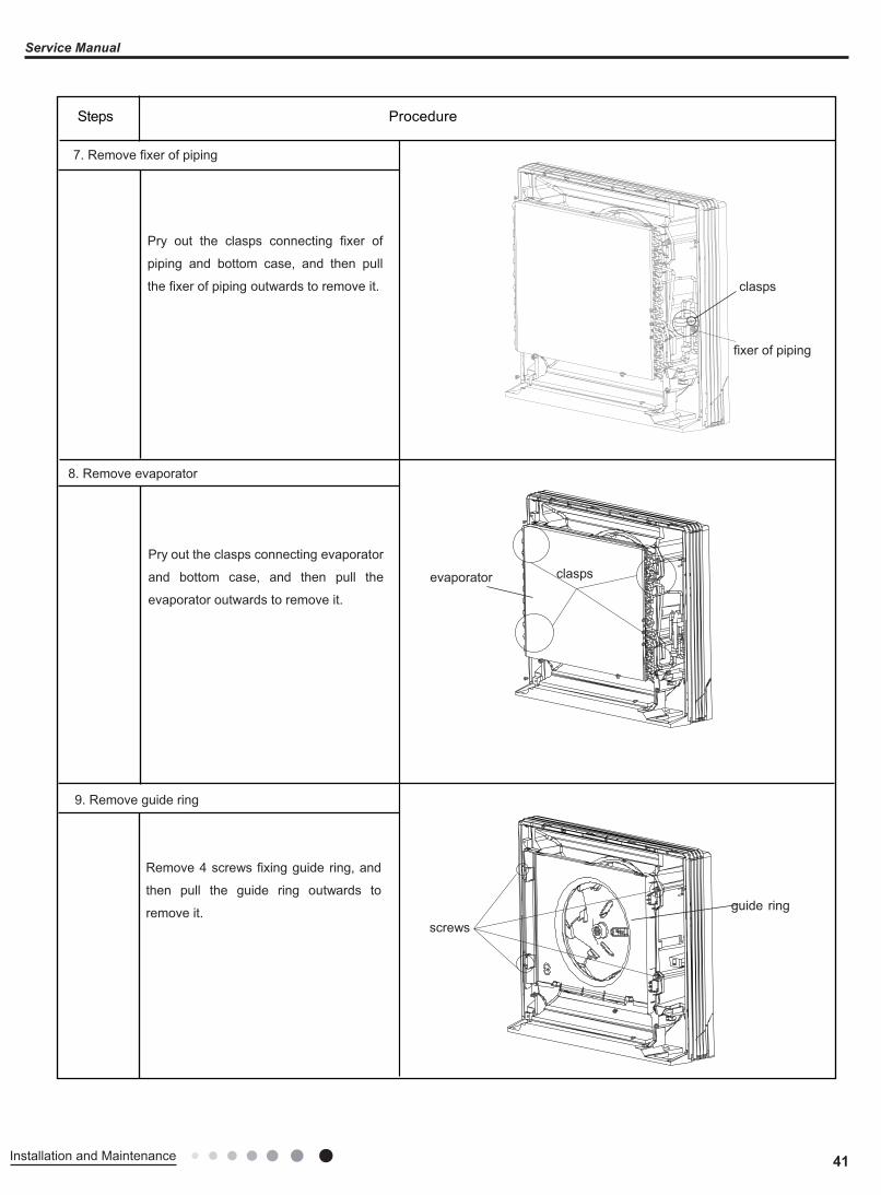
41Installation and Maintenance
Service Manual
7. Remove fixer of piping
Pry out the clasps connecting fixer of
piping and bottom case, and then pull
the fixer of piping outwards to remove it.
8. Remove evaporator
Pry out the clasps connecting evaporator
and bottom case, and then pull the
evaporator outwards to remove it.
9. Remove guide ring
Remove 4 screws fixing guide ring, and
then pull the guide ring outwards to
remove it. screws
guide ring
evaporator clasps
clasps
fixer of piping
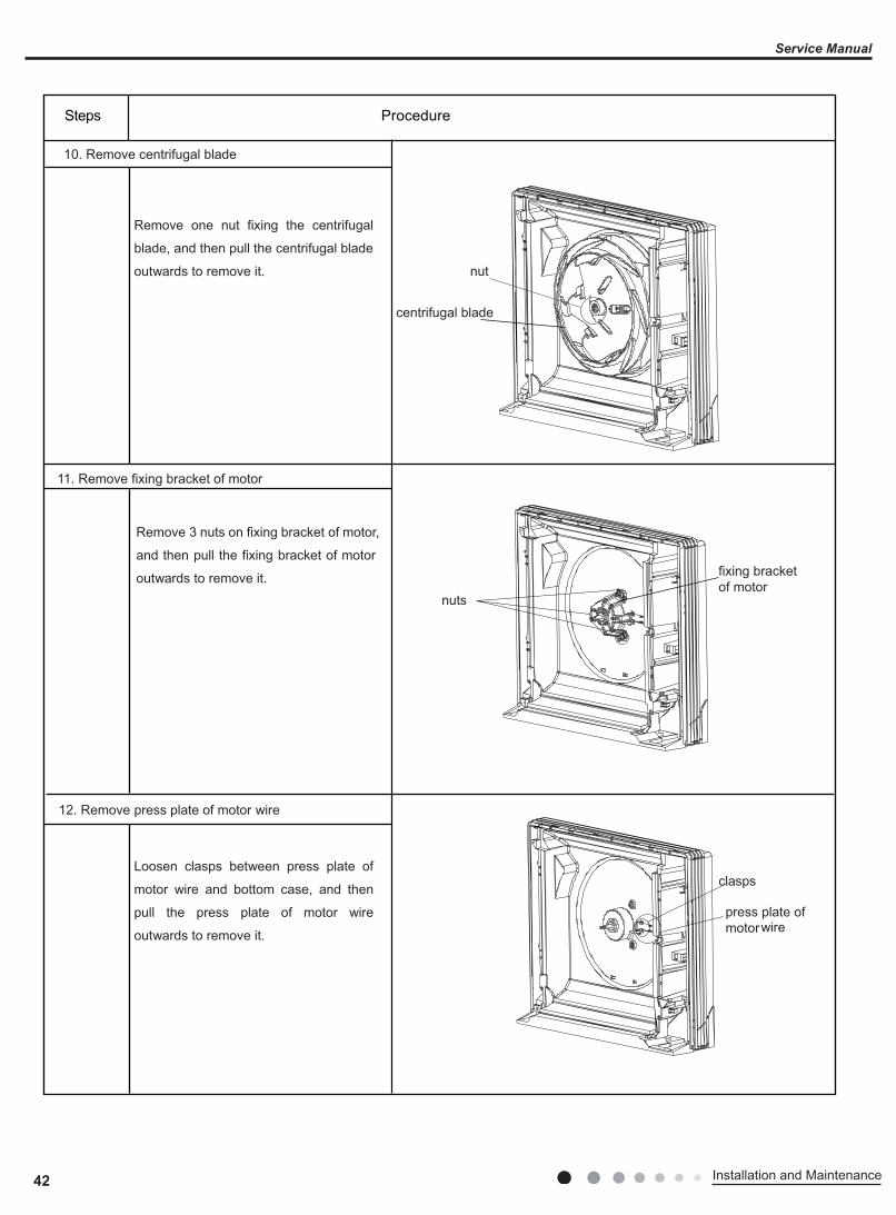
42 Installation and Maintenance
Service Manual
10. Remove centrifugal blade
Remove one nut fixing the centrifugal
blade, and then pull the centrifugal blade
outwards to remove it.
11. Remove fixing bracket of motor
Remove 3 nuts on fixing bracket of motor,
and then pull the fixing bracket of motor
outwards to remove it.
12. Remove press plate of motor wire
Loosen clasps between press plate of
motor wire and bottom case, and then
pull the press plate of motor wire
outwards to remove it.
clasps
press plate of motorwire
nuts
fixing bracket of motor
centrifugal blade
nut
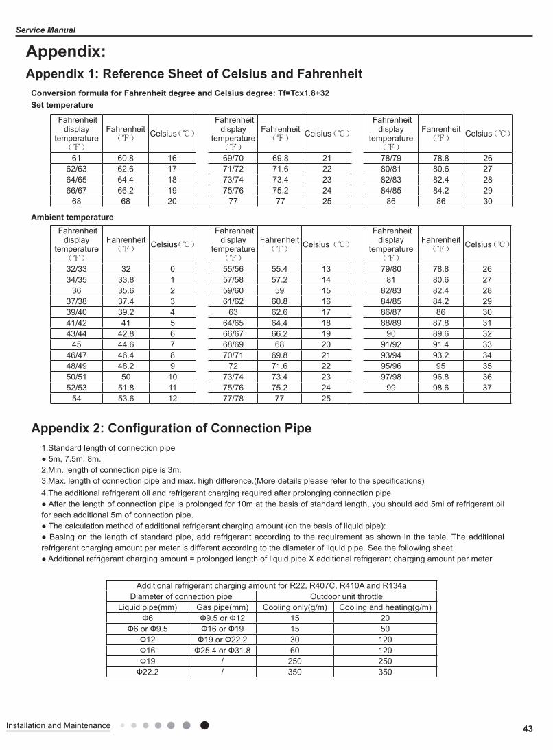
43Installation and Maintenance
Service Manual
Appendix:
1.Standard length of connection pipe● 5m, 7.5m, 8m.2.Min. length of connection pipe is 3m.3.Max. length of connection pipe and max. high difference.(More details please refer to the specifications)4.The additional refrigerant oil and refrigerant charging required after prolonging connection pipe● After the length of connection pipe is prolonged for 10m at the basis of standard length, you should add 5ml of refrigerant oil for each additional 5m of connection pipe.● The calculation method of additional refrigerant charging amount (on the basis of liquid pipe):● Basing on the length of standard pipe, add refrigerant according to the requirement as shown in the table. The additional refrigerant charging amount per meter is different according to the diameter of liquid pipe. See the following sheet.● Additional refrigerant charging amount = prolonged length of liquid pipe X additional refrigerant charging amount per meter
Appendix 1: Reference Sheet of Celsius and Fahrenheit
Appendix 2: Configuration of Connection Pipe
Set temperatureConversion formula for Fahrenheit degree and Celsius degree: Tf=Tcx1.8+32
Ambient temperature Fahrenheit
display temperature
(℉)
Fahrenheit(℉)
Celsius(℃)
Fahrenheit display
temperature(℉)
Fahrenheit(℉)
Celsius(℃)
Fahrenheit display
temperature(℉)
Fahrenheit(℉)
Celsius(℃)
32/33 32 0 55/56 55.4 13 79/80 78.8 2634/35 33.8 1 57/58 57.2 14 81 80.6 27
36 35.6 2 59/60 59 15 82/83 82.4 2837/38 37.4 3 61/62 60.8 16 84/85 84.2 2939/40 39.2 4 63 62.6 17 86/87 86 3041/42 41 5 64/65 64.4 18 88/89 87.8 3143/44 42.8 6 66/67 66.2 19 90 89.6 32
45 44.6 7 68/69 68 20 91/92 91.4 3346/47 46.4 8 70/71 69.8 21 93/94 93.2 3448/49 48.2 9 72 71.6 22 95/96 95 3550/51 50 10 73/74 73.4 23 97/98 96.8 3652/53 51.8 11 75/76 75.2 24 99 98.6 37
54 53.6 12 77/78 77 25
Fahrenheit display
temperature(℉)
Fahrenheit(℉)
Celsius(℃)
Fahrenheit display
temperature(℉)
Fahrenheit(℉)
Celsius(℃)
Fahrenheit display
temperature(℉)
Fahrenheit(℉)
Celsius(℃)
61 60.8 16 69/70 69.8 21 78/79 78.8 2662/63 62.6 17 71/72 71.6 22 80/81 80.6 2764/65 64.4 18 73/74 73.4 23 82/83 82.4 2866/67 66.2 19 75/76 75.2 24 84/85 84.2 29
68 68 20 77 77 25 86 86 30
Additional refrigerant charging amount for R22, R407C, R410A and R134aDiameter of connection pipe Outdoor unit throttle
Liquid pipe(mm) Gas pipe(mm) Cooling only(g/m) Cooling and heating(g/m)Ф6 Ф9.5 or Ф12 15 20
Ф6 or Ф9.5 Ф16 or Ф19 15 50Ф12 Ф19 or Ф22.2 30 120Ф16 Ф25.4 or Ф31.8 60 120Ф19 / 250 250
Ф22.2 / 350 350
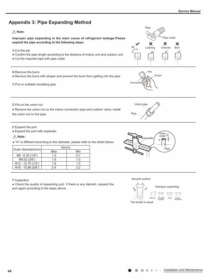
44 Installation and Maintenance
Service Manual
F:Inspection● Check the quality of expanding port. If there is any blemish, expand the port again according to the steps above.
The length is equal
Improper expanding
leaning damagedsurface
crack uneventhickness
Smooth surface
Downwards
Pipe
Shaper
Union pipe
Pipe
Expander
Hardmold
Pipe
Pipe
Pipe cutter
Leaning Uneven Burr
Improper pipe expanding is the main cause of refrigerant leakage.Please expand the pipe according to the following steps:
A:Cut the pip● Confirm the pipe length according to the distance of indoor unit and outdoor unit.● Cut the required pipe with pipe cutter.
B:Remove the burrs● Remove the burrs with shaper and prevent the burrs from getting into the pipe.
C:Put on suitable insulating pipe
D:Put on the union nut● Remove the union nut on the indoor connection pipe and outdoor valve; installthe union nut on the pipe.
E:Expand the port● Expand the port with expander.
● "A" is different according to the diameter, please refer to the sheet below:
Outer diameter(mm) A(mm)Max Min
Ф6 - 6.35 (1/4") 1.3 0.7Ф9.52 (3/8”) 1.6 1.0
Ф12 - 12.70 (1/2”) 1.8 1.0Ф16 - 15.88 (5/8”) 2.4 2.2
Appendix 3: Pipe Expanding Method
Note:
Note:
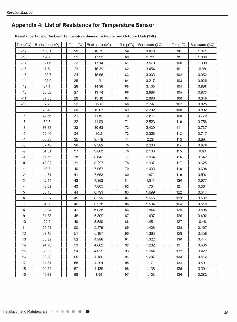
45Installation and Maintenance
Service Manual
Temp(oC) Resistance(kΩ) Temp(oC) Resistance(kΩ) Temp(oC) Resistance(kΩ) Temp(oC) Resistance(kΩ)
-19 138.1 20 18.75 59 3.848 98 1.071
-18 128.6 21 17.93 60 3.711 99 1.039
-17 121.6 22 17.14 61 3.579 100 1.009
-16 115 23 16.39 62 3.454 101 0.98
-15 108.7 24 15.68 63 3.333 102 0.952
-14 102.9 25 15 64 3.217 103 0.925
-13 97.4 26 14.36 65 3.105 104 0.898
-12 92.22 27 13.74 66 2.998 105 0.873
-11 87.35 28 13.16 67 2.896 106 0.848
-10 82.75 29 12.6 68 2.797 107 0.825
-9 78.43 30 12.07 69 2.702 108 0.802
-8 74.35 31 11.57 70 2.611 109 0.779
-7 70.5 32 11.09 71 2.523 110 0.758
-6 66.88 33 10.63 72 2.439 111 0.737
-5 63.46 34 10.2 73 2.358 112 0.717
-4 60.23 35 9.779 74 2.28 113 0.697
-3 57.18 36 9.382 75 2.206 114 0.678
-2 54.31 37 9.003 76 2.133 115 0.66
-1 51.59 38 8.642 77 2.064 116 0.642
0 49.02 39 8.297 78 1.997 117 0.625
1 46.6 40 7.967 79 1.933 118 0.608
2 44.31 41 7.653 80 1.871 119 0.592
3 42.14 42 7.352 81 1.811 120 0.577
4 40.09 43 7.065 82 1.754 121 0.561
5 38.15 44 6.791 83 1.699 122 0.547
6 36.32 45 6.529 84 1.645 123 0.532
7 34.58 46 6.278 85 1.594 124 0.519
8 32.94 47 6.038 86 1.544 125 0.505
9 31.38 48 5.809 87 1.497 126 0.492
10 29.9 49 5.589 88 1.451 127 0.48
11 28.51 50 5.379 89 1.408 128 0.467
12 27.18 51 5.197 90 1.363 129 0.456
13 25.92 52 4.986 91 1.322 130 0.444
14 24.73 53 4.802 92 1.282 131 0.433
15 23.6 54 4.625 93 1.244 132 0.422
16 22.53 55 4.456 94 1.207 133 0.412
17 21.51 56 4.294 95 1.171 134 0.401
18 20.54 57 4.139 96 1.136 135 0.391
19 19.63 58 3.99 97 1.103 136 0.382
Appendix 4: List of Resistance for Temperature Sensor
Resistance Table of Ambient Temperature Sensor for Indoor and Outdoor Units(15K)
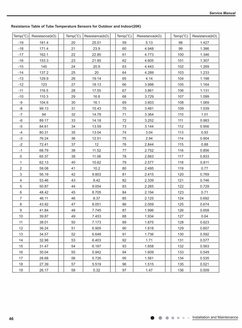
46 Installation and Maintenance
Service Manual
Temp(oC) Resistance(kΩ) Temp(oC) Resistance(kΩ) Temp(oC) Resistance(kΩ) Temp(oC) Resistance(kΩ)
-19 181.4 20 25.01 59 5.13 98 1.427
-18 171.4 21 23.9 60 4.948 99 1.386
-17 162.1 22 22.85 61 4.773 100 1.346
-16 153.3 23 21.85 62 4.605 101 1.307
-15 145 24 20.9 63 4.443 102 1.269
-14 137.2 25 20 64 4.289 103 1.233
-13 129.9 26 19.14 65 4.14 104 1.198
-12 123 27 18.13 66 3.998 105 1.164
-11 116.5 28 17.55 67 3.861 106 1.131
-10 110.3 29 16.8 68 3.729 107 1.099
-9 104.6 30 16.1 69 3.603 108 1.069
-8 99.13 31 15.43 70 3.481 109 1.039
-7 94 32 14.79 71 3.364 110 1.01
-6 89.17 33 14.18 72 3.252 111 0.983
-5 84.61 34 13.59 73 3.144 112 0.956
-4 80.31 35 13.04 74 3.04 113 0.93
-3 76.24 36 12.51 75 2.94 114 0.904
-2 72.41 37 12 76 2.844 115 0.88
-1 68.79 38 11.52 77 2.752 116 0.856
0 65.37 39 11.06 78 2.663 117 0.833
1 62.13 40 10.62 79 2.577 118 0.811
2 59.08 41 10.2 80 2.495 119 0.77
3 56.19 42 9.803 81 2.415 120 0.769
4 53.46 43 9.42 82 2.339 121 0.746
5 50.87 44 9.054 83 2.265 122 0.729
6 48.42 45 8.705 84 2.194 123 0.71
7 46.11 46 8.37 85 2.125 124 0.692
8 43.92 47 8.051 86 2.059 125 0.674
9 41.84 48 7.745 87 1.996 126 0.658
10 39.87 49 7.453 88 1.934 127 0.64
11 38.01 50 7.173 89 1.875 128 0.623
12 36.24 51 6.905 90 1.818 129 0.607
13 34.57 52 6.648 91 1.736 130 0.592
14 32.98 53 6.403 92 1.71 131 0.577
15 31.47 54 6.167 93 1.658 132 0.563
16 30.04 55 5.942 94 1.609 133 0.549
17 28.68 56 5.726 95 1.561 134 0.535
18 27.39 57 5.519 96 1.515 135 0.521
19 26.17 58 5.32 97 1.47 136 0.509
Resistance Table of Tube Temperature Sensors for Outdoor and Indoor(20K)

47Installation and Maintenance
Service Manual
Temp(oC) Resistance(kΩ) Temp(oC) Resistance(kΩ) Temp(oC) Resistance(kΩ) Temp(oC) Resistance(kΩ)
-29 853.5 10 98 49 18.34 88 4.75
-28 799.8 11 93.42 50 17.65 89 4.61
-27 750 12 89.07 51 16.99 90 4.47
-26 703.8 13 84.95 52 16.36 91 4.33
-25 660.8 14 81.05 53 15.75 92 4.20
-24 620.8 15 77.35 54 15.17 93 4.08
-23 580.6 16 73.83 55 14.62 94 3.96
-22 548.9 17 70.5 56 14.09 95 3.84
-21 516.6 18 67.34 57 13.58 96 3.73
-20 486.5 19 64.33 58 13.09 97 3.62
-19 458.3 20 61.48 59 12.62 98 3.51
-18 432 21 58.77 60 12.17 99 3.41
-17 407.4 22 56.19 61 11.74 100 3.32
-16 384.5 23 53.74 62 11.32 101 3.22
-15 362.9 24 51.41 63 10.93 102 3.13
-14 342.8 25 49.19 64 10.54 103 3.04
-13 323.9 26 47.08 65 10.18 104 2.96
-12 306.2 27 45.07 66 9.83 105 2.87
-11 289.6 28 43.16 67 9.49 106 2.79
-10 274 29 41.34 68 9.17 107 2.72
-9 259.3 30 39.61 69 8.85 108 2.64
-8 245.6 31 37.96 70 8.56 109 2.57
-7 232.6 32 36.38 71 8.27 110 2.50
-6 220.5 33 34.88 72 7.99 111 2.43
-5 209 34 33.45 73 7.73 112 2.37
-4 198.3 35 32.09 74 7.47 113 2.30
-3 199.1 36 30.79 75 7.22 114 2.24
-2 178.5 37 29.54 76 7.00 115 2.18
-1 169.5 38 28.36 77 6.76 116 2.12
0 161 39 27.23 78 6.54 117 2.07
1 153 40 26.15 79 6.33 118 2.02
2 145.4 41 25.11 80 6.13 119 1.96
3 138.3 42 24.13 81 5.93 120 1.91
4 131.5 43 23.19 82 5.75 121 1.86
5 125.1 44 22.29 83 5.57 122 1.82
6 119.1 45 21.43 84 5.39 123 1.77
7 113.4 46 20.6 85 5.22 124 1.73
8 108 47 19.81 86 5.06 125 1.68
9 102.8 48 19.06 87 4.90 126 1.64
Resistance Table of Discharge Temperature Sensor for Outdoor(50K)
JF00303247
GREE ELECTRIC APPLIANCES, INC. OF ZHUHAIAdd: West Jinji Rd, Qianshan, Zhuhai,Guangdong, China, 519070Tel: (+86-756) 8522218 Fax: (+86-756) 8669426E-mail: [email protected] www.gree.com
HONG KONG GREE ELECTRIC APPLIANCES SALES LIMITEDAdd: Unit 2612,26/F.,Miramar Tower 132 Nathan Road,TST,Kowloon,HK Tel: (852) 31658898 Fax: (852) 31651029
For product improvement, specifications and appearance in this manual are subject to change without prior notice.