Service Manual - HOSHIZAKI1. Air-Cooled Models (MAJ) Model Shown: KM-350MAJ Water Supply Inlet...
60
Models KM-350MAJ, MWJ KM-520MAJ, MWJ, MRJ KM-660MAJ, MWJ, MRJ Modular Crescent Cuber Service Manual Number: 73230 Issued: 10-29-2018 Revised: 2-27-2020 hoshizakiamerica.com
Transcript of Service Manual - HOSHIZAKI1. Air-Cooled Models (MAJ) Model Shown: KM-350MAJ Water Supply Inlet...

ModelsKM-350MAJ, MWJKM-520MAJ, MWJ, MRJKM-660MAJ, MWJ, MRJ
Modular Crescent Cuber
Service Manual
Number: 73230Issued: 10-29-2018Revised: 2-27-2020
hoshizakiamerica.com

2
WARNINGOnly qualified service technicians should install and service the appliance. To obtain the name and phone number of your local Hoshizaki Certified Service Representative, visit www.hoshizaki.com. No service should be undertaken until the technician has thoroughly read this Service Manual. Failure to service and maintain the appliance in accordance with this manual will adversely affect safety, performance, component life, and warranty coverage. Proper installation is the responsibility of the installer. Product failure or property damage due to improper installation is not covered under warranty.
Hoshizaki provides this manual primarily to assist qualified service technicians in the service of the appliance.
Should the reader have any questions or concerns which have not been satisfactorily addressed, please call, send an e-mail message, or write to the Hoshizaki Technical Support Department for assistance.
Phone: 1-800-233-1940; (770) 487-2331Fax: 1-800-843-1056; (770) 487-3360
E-mail: [email protected]
618 Highway 74 SouthPeachtree City, GA 30269Attn: Hoshizaki Technical Support Department
Web Site: www.hoshizaki.com
NOTE: To expedite assistance, all correspondence/communication MUST include the following information:
• Model Number
• Serial Number
• Complete and detailed explanation of the problem.

3
CONTENTSImportant Safety Information ................................................................................................. 5I. Construction and Water/Refrigeration Circuit Diagram ....................................................... 7
A. Construction .................................................................................................................. 71. Air-Cooled Models (MAJ) ......................................................................................... 72. Water-Cooled Models (MWJ) ................................................................................... 83. Remote Models (MRJ) ............................................................................................. 9
B. Water/Refrigeration Circuit Diagram ............................................................................ 101. Air-Cooled Models (MAJ) ....................................................................................... 102. Water-Cooled Models (MWJ) ..................................................................................113. Remote Models (MRJ) ........................................................................................... 12
II. Sequence of Operation and Service Diagnosis ............................................................... 13A. Sequence of Operation Flow Chart ............................................................................. 13
1. Operation Flow Chart ............................................................................................ 132. Shutdown Flow Chart ............................................................................................ 14
B. Service Diagnosis ....................................................................................................... 15C. Control Board Check ................................................................................................... 21D. Bin Control Check and Adjustment .............................................................................. 22E. Float Switch Check and Cleaning ............................................................................... 26F. Thermistor Check ......................................................................................................... 28G. Control Switch ............................................................................................................. 28H. Mode Switch ............................................................................................................... 28I. Diagnostic Tables .......................................................................................................... 29J. Freeze-Up Check List .................................................................................................. 33
III. Controls and Adjustments ............................................................................................... 34A. Control Board Layout .................................................................................................. 35B. LED Lights and Audible Alarm Safeties ....................................................................... 36C. Settings and Adjustments ............................................................................................ 37
1. Default Dip Switch Settings .................................................................................... 372. Harvest Time (S4 dip switch 1 & 2)........................................................................ 383. Pump-Out Time/Harvest Time During Pump-Out (S4 dip switch 3 & 4) ................. 384. Pump-Out Frequency Control (S4 dip switch 5) ..................................................... 395. Harvest Pump Time (Harvest Assist) (S4 dip switch 6) ......................................... 396. Harvest Pump Time (Harvest Assist (S4 dip switch 7) .......................................... 407. Factory Use (S4 dip switch 8)................................................................................. 408. Freeze Timer (S4 dip switch 9 & 10) ...................................................................... 409. Pump-Out Pump Motor Direction (S5 dip switch 1) ............................................... 4110. Refill Counter (S5 dip switch 2 and 3) .................................................................. 4111. Minimum Harvest Time (S5 dip switch 4) ............................................................. 4112. Anti-Slush (S5 dip switch 5) ................................................................................. 42
IMPORTANTThis manual should be read carefully before the appliance is serviced. Read the warnings and guidelines contained in this manual carefully as they provide essential information for the continued safe use, service, and maintenance of the appliance. Retain this manual for any further reference that may be necessary.

4
IV. Refrigeration Circuit and Component Service Information.............................................. 43A. Refrigeration Circuit Service Information .................................................................... 43B. Component Service Information .................................................................................. 46C. Water Regulating Valve Adjustment (water-cooled model) .......................................... 47
V. Maintenance .................................................................................................................... 48VI. Preparing the Appliance for Periods of Non-Use ............................................................ 49VII. Disposal ......................................................................................................................... 51VIII. Technical Information .................................................................................................... 52
A. Specification and Performance Data Sheets ............................................................... 521. KM-350MAJ ........................................................................................................... 522. KM-350MWJ .......................................................................................................... 533. KM-520MAJ ........................................................................................................... 544. KM-520MWJ .......................................................................................................... 555. KM-520MRJ with URC-5F ..................................................................................... 566. KM-660MAJ ........................................................................................................... 577. KM-660MWJ .......................................................................................................... 588. KM-660MRJ with URC-5F ..................................................................................... 59
B. Wiring Diagram ........................................................................................................... 60

5
Important Safety InformationThroughout this manual, notices appear to bring your attention to situations which could result in death, serious injury, damage to the appliance, or damage to property.
WARNING Indicates a hazardous situation which could result in death or serious injury.
NOTICE Indicates a situation which could result in damage to the appliance or property.
IMPORTANT Indicates important information about the use and care of the appliance.
WARNINGThe appliance should be destined only to the use for which it has been expressly conceived. Any other use should be considered improper and therefore dangerous. The manufacturer cannot be held responsible for injury or damage resulting from improper, incorrect, and unreasonable use. Failure to service and maintain the appliance in accordance with this manual will adversely affect safety, performance, component life, and warranty coverage and may result in costly water damage.To reduce the risk of death, electric shock, serious injury, or fire, follow basic precautions including the following:
• Only qualified service technicians should install and service this appliance.
• The appliance must be installed in accordance with applicable national, state, and local codes and regulations.
• Electrical connection must be hard-wired and must meet national, state, and local electrical code requirements. Failure to meet these code requirements could result in death, electric shock, serious injury, fire, or severe damage to equipment.
• The icemaker requires an independent power supply of proper capacity. See the nameplate for electrical specifications. Failure to use an independent power supply of proper capacity can result in a tripped breaker, blown fuses, damage to existing wiring, or component failure. This could lead to heat generation or fire.
• THE ICEMAKER MUST BE GROUNDED. Failure to properly ground the icemaker could result in death or serious injury.
• Move the control switch to the "OFF" position and turn off the power supply before servicing. Lockout/Tagout to prevent the power supply from being turned back on inadvertently.
• To reduce the risk of electric shock, do not touch the control switch with damp hands.
• Do not make any alterations to the unit. Alterations could result in electric shock, injury, fire, or damage to the unit.
• The appliance is not intended for use by persons (including children) with reduced physical, sensory, or mental capabilities, or lack of experience and knowledge, unless they have been given supervision or instruction concerning use of the appliance by a person responsible for their safety.

6
WARNING, continued• Children should be properly supervised around this appliance.
• Do not climb, stand, or hang on the appliance or allow children or animals to do so. Serious injury could occur or the appliance could be damaged.
• Do not use combustible spray or place volatile or flammable substances near the appliance. They might catch fire.
• Keep the area around the appliance clean. Dirt, dust, or insects in the appliance could cause harm to individuals or damage to the appliance.
Additional Warning for Remote Models
• THE REMOTE CONDENSER UNIT MUST BE GROUNDED. The power supply and ground connection to the remote condenser unit are supplied from the icemaker. Failure to properly ground the remote condenser unit could result in death or serious injury.
• Move the icemaker control switch to the "OFF" position and turn off the power supply to the icemaker before servicing the remote condenser unit. Lockout/Tagout to prevent the power supply from being turned back on inadvertently.
NOTICE• Follow the instructions in this manual carefully to reduce the risk of costly water
damage.
• In areas where water damage is a concern, install in a contained area with a floor drain.
• Install the appliance in a location that stays above freezing. Normal operating ambient temperature must be within 45°F to 100°F (7°C to 38°C).
• Do not leave the icemaker on during extended periods of non-use, extended absences, or in sub-freezing temperatures. To properly prepare the icemaker for these occasions, follow the instructions in "VI. Preparing the Appliance for Periods of Non-Use."
• Do not place objects on top of the appliance.
• The dispenser unit/ice storage bin is for ice use only. Do not store anything else in the dispenser unit/ice storage bin.

7
I. Construction and Water/Refrigeration Circuit Diagram
A. Construction
1. Air-Cooled Models (MAJ)
Model Shown: KM-350MAJ
Water Supply Inlet
Condenser
Drier
Control Box
Spray Tubes
Control Switch
Water Pump
Float Switch
Compressor
Thermostatic Expansion Valve Fan Motor
Hot Gas Valve
Cleaning Valve
Bin ControlSensor
Inlet Water ValveHigh-Pressure Switch
Liquid Line Valve
Evaporator
Stainer
Mode Switch
Drain Valve

8
2. Water-Cooled Models (MWJ)
Water Supply Inlet
Condenser
Drier
Control Box
Spray Tubes
Control Switch
Water Pump
Float Switch
Compressor
Thermostatic Expansion Valve
Water Regulating Valve
Hot Gas Valve
Cleaning Valve
Model Shown: KM-520MWJ
Inlet Water Valve
Liquid Line Valve
High-Pressure Switch
Bin Control Sensor
Evaporator Stainer
Mode Switch
Drain Valve

9
3. Remote Models (MRJ)
Receiver Tank
Water Supply Inlet
Drier
Spray Tubes
Control Switch
Water Pump
Float Switch
Compressor
Thermostatic Expansion Valve
Hot Gas Valve
Liquid Line Valve
Cleaning Valve
Model Shown: KM-660MRJ
Inlet Water Valve
Crankcase Heater
Stainer
High-Pressure Switch
Evaporator
Bin ControlSensor
Control BoxMode Switch
Drain Valve

10
B. Water/Refrigeration Circuit Diagram
1. Air-Cooled Models (MAJ)
Wat
er S
uppl
y
Flo
at S
witc
h
Dra
in
The
rmos
tatic
Exp
ansi
on V
alve
Com
pres
sor
Hot
Gas
V
alve
Hig
h-P
ress
ure
Sw
itch
Str
aine
r
Fan
Drie
r
Con
dens
er
Eva
pora
tor
Dis
char
ge L
ine
Suc
tion
Line
Wat
er P
ump
The
rmis
tor
Spr
ay T
ubes
Inle
t Wat
er V
alve
Wat
er T
ank
Ref
riger
atio
n C
ircui
t
Wat
er C
ircui
t
Hea
t E
xcha
nger
Liqu
id L
ine
Val
ve
Cle
anin
g V
alve
Dra
in V
alve

11
2. Water-Cooled Models (MWJ)
Wat
er S
uppl
y
Flo
at S
witc
h
Dra
in
The
rmos
tatic
Exp
ansi
on V
alve
Com
pres
sor
Hot
Gas
V
alve
Hig
h-P
ress
ure
Sw
itch
Str
aine
r
Drie
r
Con
dens
erE
vapo
rato
r
Dis
char
ge L
ine
Suc
tion
Line
Wat
er P
ump
The
rmis
tor
Spr
ay T
ubes
Inle
t Wat
er V
alve
Wat
er T
ank
Ref
riger
atio
n C
ircui
t
Wat
er C
ircui
t
Hea
t E
xcha
nger
Liqu
id L
ine
Val
ve
Wat
er R
egul
atin
g V
alve
Cle
anin
g V
alve
Dra
in V
alve

12
3. Remote Models (MRJ)
Wat
er S
uppl
y
Flo
at S
witc
h
Dra
in
Com
pres
sor
Hot
Gas
V
alve
Hig
h-P
ress
ure
Sw
itch
Str
aine
r
Fan
Drie
r
Rem
ote
Con
dens
er
Eva
pora
tor
Dis
char
ge L
ine
Suc
tion
Line
Wat
er P
umpT
herm
isto
r
Spr
ay T
ubes
Inle
t Wat
er V
alve
Wat
er T
ank
Ref
riger
atio
n C
ircui
t
Wat
er C
ircui
t
Liqu
id L
ine
Val
ve
Rec
eive
r
Hea
dmas
ter
(C.P
.R.)
The
rmos
tatic
Exp
ansi
on
Val
ve
Hea
t E
xcha
nger
Cle
anin
g V
alve
Dra
in V
alve

13
II. Sequence of Operation and Service Diagnosis
A. Sequence of Operation Flow Chart
1. Operation Flow Chart
FS
che
ck
1 to
3-m
in. h
arve
st ti
mer
in
cont
rol (
S4
dip
switc
h 1
& 2
)
Leg
end
: B
C–b
in c
ontr
olC
om
p–c
ompr
esso
rD
V–d
rain
val
veF
M–f
an m
otor
FM
R–f
an m
otor
-rem
ote
FS
–floa
t sw
itch
HG
V–h
ot g
as v
alve
LLV
–liq
uid
line
valv
eP
M–p
ump
mot
orW
V–i
nlet
wat
er v
alve
Co
mp
on
ents
En
erg
ized
wh
en t
he
Co
ntr
ol S
wit
ch is
in t
he
"PU
MP
" P
osi
tio
nW
hen
the
cont
rol s
witc
h is
in th
e "P
UM
P"
posi
tion
pow
er is
sup
plie
d to
the
pum
p m
otor
. Wat
er ta
nk c
onte
nts
then
flow
s ov
er th
e ou
tsid
e of
the
evap
orat
or p
late
ass
embl
y. N
ote:
Wat
er ta
nk c
onte
nts
does
not
flow
in-b
etw
een
the
evap
orat
or p
late
s.
Op
erat
ion
Flo
w C
har
t
1. 1
-Min
ute
Fi
ll C
ycle
Cyc
le
Ste
ps
2. H
arve
st C
ycle
• W
V ti
me:
6 m
in. o
r th
e le
ngth
of h
arve
st m
inus
50
sec.
(S
4 di
p sw
itch
7), w
hich
ever
is s
hort
er. D
o no
t adj
ust S
4 di
p sw
itch
7 ou
t of t
he fa
ctor
y po
sitio
n.•
Max
. har
vest
tim
e: 2
0 m
in.
The
rmis
tor
in c
ontr
ol
3. F
reez
e C
ycle
• M
in. f
reez
e tim
e: 5
min
.•
Max
. fre
eze
time:
free
ze ti
mer
set
ting
(S4
dip
switc
h 9
& 1
0).
FS
in c
ontr
ol
4. P
um
p-O
ut
Cyc
le•
Fact
ory
set f
or e
very
10t
h cy
cle
(S
4 di
p sw
itch
5)•
Pum
p m
otor
sto
ps fo
r 2
sec.
, the
n en
ergi
zes
for
10/2
0 se
c.
(S4
dip
switc
h 3
& 4
)
WV
ene
rgiz
ed
FS
ope
n
Co
mp
ene
rgiz
edF
MR
ene
rgiz
edH
GV
ene
rgiz
edW
V e
nerg
ized
The
rmis
tor
tem
pera
ture
rea
ches
48
°F (
9°C
) (3
.9 k
Ω o
r le
ss).
H
arve
st ti
mer
sta
rts.
FS
ope
n
Co
mp
ene
rgiz
edF
M e
nerg
ized
FM
R e
nerg
ized
PM
ene
rgiz
edL
LV e
nerg
ized
HG
V d
e-en
ergi
zed
FS
clo
sed
Co
mp
ene
rgiz
edD
V e
nerg
ized
FM
R e
nerg
ized
HG
V e
nerg
ized
PM
de-
ener
gize
s fo
r 2
sec.
,
th
en e
nerg
izes
for
10/2
0 se
c.F
M d
e-en
ergi
zed
LLV
de-
ener
gize
d
FS
che
ckS
tart
up
If F
S is
ope
n, C
omp
stop
s an
d cy
cle
retu
rns
to
1-M
in. fi
ll.
5-m
in.
min
imum
fr
eeze
tim
er in
co
ntro
l
FS
clo
sed
FS
ope
ns o
r fr
eeze
tim
er te
rmin
ates
50 s
ec.
PM
ene
rgiz
edW
V d
e-en
ergi
zedH
arve
st P
um
p
Tim
er
An
ti-S
lush
The
rmis
tor
tem
pera
ture
reac
hes
36°F
(2.
2°C
)(5
.8 k
Ω).
PM
de-
ener
gize
d fo
r10
sec
.
Co
mp
on
ents
En
erg
ized
wh
en t
he
Co
ntr
ol S
wit
ch is
in t
he
"ON
" o
r "P
UM
P"
po
siti
on
an
d t
he
Mo
de
Sw
itch
is
in t
he
"CL
EA
N"
Po
siti
on
• W
hen
the
cont
rol s
witc
h is
in th
e "O
N"
posi
tion
and
the
mod
e sw
itch
is in
the
"CLE
AN
" po
sitio
n po
wer
is s
uppl
ied
to th
e co
ntro
l boa
rd K
9 co
nnec
tor.
The
con
trol
boa
rd
then
initi
ates
a c
lean
/san
itize
pro
gram
. See
the
mai
nten
ance
labe
l on
the
top
cove
r or
the
inst
ruct
ion
man
ual f
or d
etai
ls.
• W
hen
the
cont
rol s
witc
h is
in th
e "P
UM
P"
posi
tion
and
the
mod
e sw
itch
is in
the
"CLE
AN
" po
sitio
n, o
nly
the
pum
p m
otor
ene
rgiz
es a
nd c
ircul
ates
wat
er ta
nk c
onte
nts
over
out
side
of e
vapo
rato
r pl
ate
asse
mbl
y as
the
cont
rol b
oard
pow
er s
uppl
y ha
s be
en d
isco
nnec
ted.
The
Cle
an/S
aniti
ze p
rogr
am c
anno
t ini
tiate
in th
is s
cena
rio.

14
2. Shutdown Flow Chart
Sh
utd
ow
n F
low
Ch
art
1. B
in F
ull
Sh
utd
ow
n D
elay
:•
Fill
Cyc
le–1
5 se
c. a
fter
activ
atio
n.•
Har
vest
Cyc
le–A
t the
end
of t
he h
arve
st c
ycle
, or
up
to
15 s
ec. i
nto
the
free
ze c
ycle
if
act
ivat
ed a
t the
end
of t
he h
arve
st c
ycle
. •
Free
ze C
ycle
– 1
5 se
c. a
fter
activ
atio
n if
activ
ated
at l
east
1
5 se
c. b
efor
e th
e 5-
min
. sho
rt c
ycle
p
rote
ctio
n tim
er te
rmin
ates
.
O
ther
wis
e, a
t the
end
of t
he n
ext h
arve
st
cyc
le.
Sh
utd
ow
n
and
Res
tart
BC
Ope
ratio
n
BC
ope
n (B
C s
enso
r en
gage
d)
C
B Y
ello
w "
BC
OP
EN
/CLO
SE
D"
LED
on
BC
Con
trol
ler
Gre
en "
LED
1" L
ED
off
BC
ope
n (B
C s
enso
r en
gage
d)
C
B Y
ello
w"B
C O
PE
N/C
LOS
ED
"
LE
D c
ontin
ues
BC
Con
trol
ler
Gre
en "
LED
1" L
ED
off
All
com
pone
nts
de-e
nerg
ized
.
2. Ic
emak
er O
ff
All
com
pone
nts
de-e
nerg
ized
.
3. Ic
e L
evel
Lo
wer
ed Ic
emak
er s
tart
s at
"
1. 1
-Min
ute
Fill
Cyc
le."
BC
clo
sed
(BC
sen
sor
dise
ngag
ed)
B
C C
ontr
olle
r G
reen
"LE
D1"
LE
D o
n
CB
Yel
low
"B
C O
PE
N/C
LOS
ED
" LE
D o
ff
To 1
. 1-M
inu
te F
ill C
ycle
Leg
end
:B
C–b
in c
ontr
olC
B–c
ontr
ol b
oard

15
B. Service Diagnosis
WARNING• The appliance should be diagnosed and repaired only by qualified service
personnel to reduce the risk of death, electric shock, serious injury, or fire.
• Risk of electric shock. Control switch in "OFF" position does not de-energize all loads Use extreme caution and exercise safe electrical practices.
• Moving parts (e.g., fan blade) can crush and cut. Keep hands clear.
• Before servicing the appliance, move the control switch to the "OFF" position and turn off the power supply.
• CHOKING HAZARD: Ensure all components, fasteners, and thumbscrews are securely in place after the appliance is serviced. Make sure that none have fallen into the dispenser unit/ice storage bin.
• Make sure all food zones in the appliance and dispenser unit/ice storage bin are clean after service.
The diagnostic procedure is a sequence check that allows you to diagnose the electrical system and components. Before proceeding, check for correct installation, proper voltage per nameplate, and adequate water supply. Check CB using the steps in "II.C. Control Board Check." Check dip switch settings to assure that S4 dip switches and S5 dip switches 1 through 5 are in the factory default position. S4 dip switch 1, 2, 3, 4, and 5 are cleaning adjustments and the settings are flexible. For factory default settings, see "III.C.1. Default Dip Switch Settings."
Note: • When checking high voltage (115VAC), always choose a white (W) neutral wire to establish a good neutral connection.
• When checking voltage from the CB K1 connector (10 pin connector), pull CB K1 connector out slightly to allow room for multimeter test leads contact.
1) Turn off the power supply, then access the control box. Move the control switch to the "OFF" position. Clear ice from BC sensing area.
2) Check that the 115VAC 10A fuse is good.

16
1. Sequence and Component Diagnosis3) Power On: Turn on the power supply, then move the control switch to the "ON"
position and the mode switch to the "ICE" position. A 5-sec. delay occurs. CB red "POWER OK" LED turns on. If CB yellow "BC OPEN" LED is on (indicating a full bin), move ice away from BC sensing area.
Note: • CB red "POWER OK" LED remains on unless the 10.5VAC power supply is interrupted (K2 connector).
• Check CB using the steps in "II.C. Control Board Check" or BC using steps in "II.D. Bin Control Check and Adjustment."
a) Power On Diagnosis: If CB red "POWER OK" LED is off, confirm 10A fuse is good. Check for 115VAC at control switch #2 (BK) to neutral (W) then at control switch #1 (P) to neutral (W). If 115VAC is present on #2 (BK) and not on #1 (P), replace control switch. If 115VAC is present on control switch #1 (P), check for 115VAC at HPS (P) to neutral (W) then HPS (BK) to neutral (W). If 115VAC is present at HPS (P) and not at HPS (BK), HPS is open. See HPS Diagnosis below. If 115VAC is present at HPS (BK), check for 10.5VAC at CB K2 #1 red wire to CB K2 #2 red wire. If 10.5VAC is not present, check that the cleaning valve is closed and the interlock switch is closed. Next, check CT continuity. If open, replace CT.
b) HPS Diagnosis: Check that the condenser coil is not clogged or restricted. Let refrigeration circuit pressures equalize. If HPS does not reset and pressures are equalized, replace HPS. If pressures are not equalized, reclaim refrigerant and diagnose refrigeration circuit restriction. Check that there are no restrictions in the refrigeration circuit. Harvest Cycle: HGV, strainer, or check valve. Freeze Cycle: FM, FMR, TXV, WRV, HM, LLV, strainer, check valve, drier, and damaged line set or fitting.
Confirm that the location meets installation requirements:
• The appliance is not intended for outdoor use. Normal operating ambient temperature should be within 45°F to 100°F (7°C to 38°C).
• Allow 6" (15 cm) clearance at rear, sides, and top for proper air circulation and ease of maintenance and/or service should they be required.
• The appliance should not be located in a corrosive environment.
4) 1-Min. Fill Cycle – LED 4 is on. WV energizes. After 1 min., CB checks for a closed FS. If FS is closed, the harvest cycle begins. If harvest cycle begins (Comp, HGV, FMR energized), continue to step 5a. If FS is open, WV remains energized until FS closes (low water safety protection during initial start up and at the end of each harvest). Diagnosis: Check that water enters the water tank. If not, check that the water supply line shut-off valve is open and screens or external filters are clear. Check for 115VAC at CB K1 #6 (O) to neutral (W). If 115VAC is not present, replace CB. If 115VAC is present, and WV does not energize, check for 115VAC at WV. If 115VAC is present, check coil continuity. If open, replace WV. If the water tank fills, but the appliance fails to start harvest (Comp energized), check for open FS. See "II.E. Float Switch Check and Cleaning." If FS is closed and CB fails to start the harvest cycle after 1 min., replace CB.

17
5a) Initial Harvest Cycle – LEDs 1, 4, and 2 are on. WV continues. Comp, FMR, and HGV energize. CB monitors the warming of the evaporator via the thermistor located on the suction line. When the thermistor reaches 48°F (9°C), CB reads 3.9 kΩ from the thermistor and turns harvest termination over to the harvest timer (S4 dip switch 1 & 2 and S5 dip switch 4). WV are energized during harvest for a maximum of 6 min. or the length of harvest minus HPT setting (S4 dip switch 6), whichever is shorter. See step 5b below.
a) Comp Diagnosis: Check that evaporator is warming. If not, confirm that Comp energizes. If not, check for 115VAC at CB K1 #9 (Y) to neutral (W). If 115VAC is not present, check for 115VAC at CB K1 #10 (BK) to neutral (W). If 115VAC is present at #10 (BK) and not at #9 (Y), replace CB. If 115VAC is present, check for 115VAC at mode switch #2 (Y) to neutral and mode switch #1 (V) to neutral. If 115VAC is present at #2 (Y) and not at #1 (V), confirm mode switch is in "ICE" position. If in "ICE" position, check mode switch continuity. If open, replace mode switch. If 115VAC is present at mode switch #1 (V), check for 115VAC at CR solenoid. If 115V AC is present, confirm contacts are closed. If not, replace CR. If CR contacts are closed, check Comp external overload, Comp start and run capacitors, Comp start relay, and Comp motor winding.
b) HGV Diagnosis: If Comp is energized and evaporator is not warming, check that HGV energizes and opens. Check for 115VAC at CB K1 #2 (P) to neutral (W). If 115VAC is not present, check for 115VAC at CB K1 #1 (V). If 115VAC is not present, check wiring for loose connection from CB 10 pin connector pin #1 (V) to mode switch. If 115VAC is present on #1 (V) and not at #2 (P), replace CB. If 115VAC is present at #2 (P), check for 115VAC at HGV coil and check HGV coil continuity. Replace as needed. Note: LED is off when HGV is energized and on when LLV/FM are energized.
c) LLV Diagnosis: Confirm that LLV is de-energized and closed (not bypassing). If energized, replace CB. If de-energized and bypassing, replace LLV.
d) WRV Diagnosis: Confirm WRV is not leaking by. If WRV is leaking by, confirm HGV is open and LLV is closed. Next, check for proper refrigerant pressures. If refrigerant pressures are correct, adjust or replace WRV. See "IV.C. Water Regulating Valve Adjustment (water-cooled models).".
5b) Harvest Pump Time (Harvest Assist) – LEDs 1 and 3 are on. When the thermistor reaches 48°F (9°C), CB reads 3.9 kΩ from the thermistor and turns harvest termination over to the harvest timer (S4 dip switch 1 & 2 and S5 dip switch 4). When WV de-energizes, LED 4 turns off and LED 3 turns on. PM energizes. Comp, FMR, and HGV continue. Diagnosis: Place a thermometer on the suction line next to the thermistor. Has it warmed to 48°F (9°C) or warmer? Confirm thermistor status. See "II.F. Thermistor Check." If the thermistor reading is in proper range, dip switch 7 is on, and PM does not energize before harvest terminates, replace CB. If WV continues, check for 115VAC at CB K1 #6 (O). If 115VAC is present, and LED 4 is off, replace CB. If LED 3 is on and PM is not energized, check for 115VAC at CB K1 #4 (R). If 115VAC is not present, replace CB. If 115VAC is present and PM is not energized, check PM capacitor and motor winding continuity.

18
5c) Initial Harvest Cycle Termination Diagnosis: When the thermistor reaches 48°F (9°C), CB reads 3.9 kΩ from the thermistor and turns harvest termination over to the harvest timer (S4 dip switch 1 & 2 and S5 dip switch 4). Check discharge line temperature. For a thermistor check, see "II.F. Thermistor Check." If 1-min. fill cycle starts after harvest timer terminates, check that FS is clean and operating properly, see "II.E. Float Switch Check and Cleaning." If FS is closed, CB proceeds to the next cycle. If not, replace CB.Note: The minimum total time allowed by CB for a complete harvest cycle is based onS5 dip switch 4. Maximum harvest time allowed is 20 min.
NOTICE! S4 dip switch 7 must remain on. Otherwise, PM will not energize during the last seconds of harvest.
6) Freeze Cycle – LED 1, 2, and 3 are on. Comp, FMR, and PM continue. FM and LLV energize. HGV de-energizes. Appliance is held in freeze by a 5-min. short cycle protection timer. After 5-min. short cycle protection timer terminates and FS opens, freeze cycle terminates. Note: PM power supply continues from CB K1 #4 (R) in harvest and in freeze. Anti-Slush: When anti-slush is enabled (S5 dip switch 5 "ON"), PM de-energizes when thermistor reaches 36°F (2.2°C) (5.8 kΩ) for 10 sec. then, energizes for the remainder of the freeze cycle.
a) Freeze Cycle Diagnosis: Confirm Comp, FMR, and PM continue. Confirm that FM and LLV energize. Confirm WRV opens. Next, confirm HGV de-energizes. During the first 5 min. of freeze, confirm evaporator is cooling. If not, confirm WV de-energized (not leaking by), HGV de-energized (not bypassing), LLV and FM energize, TXV and HM operate correctly, WRV opens, Comp is efficient, and refrigerant charge is correct. See "VIII.A. Specification and Performance Data Sheets."
b) Comp and FMR Diagnosis: If Comp and FMR de-energize once freeze begins, check that appliance has not shut off on HPS (CB "POWER OK" LED off). If so, check "3)b) HPS Diagnosis" above. If CB "POWER OK" LED is on, check for 115VAC at CB K1 #9 (Y) to neutral (W). If 115VAC is not present and LED 1 is on, replace CB. If 115VAC is present, check for 115VAC at CR coil. If 115VAC is present, check CR coil and contact continuity. Replace as needed. If CR is okay, check Comp start relay and start and run capacitors. Next, check Comp motor winding continuity. If Comp is energized but evaporator is not cooling, check for an inefficient Comp. See "VIII.A. Specification and Performance Data Sheets." If Comp is energized but FMR is not, check for 115VAC at the FMR junction box. If 115VAC is not present, check icemaker wiring connections. If 115VAC is present, check for voltage at condenser unit. If 115VAC is not present, check field wiring connections. If 115VAC is present, check FMR capacitor, motor winding, and fan blade for binding.
c) WV and HGV Diagnosis: If WV is energized, check for 115VAC at CB K1 #6 (O) to neutral (W). If 115VAC is present after PM energizes in harvest cycle, replace CB. If 115VAC is not present, replace WV (bypassing). If HGV did not de-energize at the end of harvest, check for 115VAC at CB K1 #2 (P) to neutral (W). If 115VAC is present and LED 2 is on, replace CB. If 115VAC is not present, replace HGV (bypassing).

19
d) PM Diagnosis: Confirm water is flowing over evaporator from PM and not WV. If PM de-energizes once freeze begins, check for 115VAC at CB K1 #4 (R) to neutral (W). If 115VAC is not present, replace CB. If 115VAC is present and PM is de-energized, check PM capacitor and motor winding continuity.
e) FM and LLV Diagnosis: If FM or LLV does not energize, check for 115VAC at CB K1 #3 (BK) to neutral (W). If 115VAC is not present and LED 2 is on, check for 115VAC at CB K1 #1 (V). If 115VAC is present at #1 (V) and not at #3 (BK), replace CB. If 115VAC is present and LED 2 is on: For FM, check capacitor, motor winding, and blade for binding. For LLV, check coil voltage and continuity. Note: LED 2 is on for LLV/FM and off for HGV.
f) Refrigerant Pressures, HM, and TXV Diagnosis: If evaporator is still not cooling, check refrigerant pressures. See "VIII.A. Specification and Performance Data Sheets." Next, check HM operation. If refrigeration pressures are above HM setpoint and HM is bypassing, replace HM. Check TXV for proper operation. Remove TXV bulb and hold it in your hand, refrigerant low-side pressure should rise, place TXV bulb in ice water, refrigerant low-side pressure should drop. A 10 to 15 pound pressure swing between warm and cold conditions indicate a good TXV. If a 10 to 15 pound swing is not present, replace TXV.
g) WRV Diagnosis: WRV is factory set and generally no adjustment is required. If WRV fails to open in freeze, check for proper refrigerant pressures. See "VIII.A. Specification and Performance Data Sheets." If refrigerant pressures are correct and WRV does not open, adjust or replace as needed. See "IV.C. Water Regulating Valve Adjustment (water-cooled models)."
h) Freeze Termination Diagnosis: After 5 min. in freeze, disconnect CB K5 FS connector. 15 sec. later appliance should switch out of the freeze cycle (15 second delay after FS opens before terminating the freeze cycle). If appliance remains in freeze longer than 15 sec. after FS removed, replace CB. If appliance switches with FS removed but would previously not switch out of freeze with FS connected (long freeze - 3 beep alarm), see "II.E. Float Switch Check and Cleaning."
Note: Normal freeze cycle will last 20 to 40 min. depending on model and conditions. Cycle times and pressures should follow performance data provided in this manual. See "VIII.A. Specification and Performance Data Sheets."
i) Short Freeze Cycle Diagnosis: Confirm water tank fills and overflows during 1 min. fill and harvest cycles. If not, check water supply filters, shut-off valve, WV screen. If water tank empties before 5 min. timer terminates and freeze cycle is short, check that DV is not leaking by (water flowing down the drain). If DV is leaking by, remove and clean DV, replace if necessary. If water tank is full, see "II.E. Float Switch Check and Cleaning." for erratic operating FS.

20
7) Pump-Out Cycle – LEDs 1, 3, and 5 are on (10/20 second pump-out). Timing of the first pump-out is determined by S4 dip switch 5. See the table below.
Control Board Settings
S4 Dip Switch SettingPump-Out Frequency Control Board
No. 5
OFF Every 10 cycles After 11th freeze cycle
ON Every cycle After 2nd freeze cycle
Comp and FMR continue, HGV energizes. Note: If S4 dip switch 3 & 4 are set to 3 off and 4 on, LED 4 turns on and WV energizes. NOTICE! S5 dip switch 1 must not be adjusted. This is the pump-out circulation selection and allows DV to energize in pump-out. FM and LLV de-energize. PM stops for 2 sec., then PM and DV energize for 10/20 sec. depending on pump-out timer (S4 dip switch 3 & 4) setting. When the pump-out timer terminates, pump-out is complete. The pump-out frequency control (S4 dip switch 5) is factory set, and generally no adjustment is required. However, the pump-out frequency control can be set to have a pump-out occur every 10 cycles or every cycle. For details, see "III.C.4. Pump-Out Frequency Control (S4 dip switch 5)."
Pump-Out Diagnosis: In the freeze cycle before pump-out (see table above), after 5 min. of freeze disconnect CB black K5 connector (FS connector). Check that PM stops and re-starts. Next, check that PM and DV energized (water flowing down the drain through DV). If PM does not stop and re-start, check that CB LEDs 1, 3, and 5 are on. If not, replace CB. If LEDs 1, 3, and 5 are on and PM does not energize, check for 115VAC at CB K1 #4 (R) to neutral (W). If 115VAC is not present, replace CB. If not, check PM motor windings and impeller for binding. If energized, make sure DV energized. If not, check for 115VAC at CB K1 #5 (W/BU). If 115VAC is not present and LED 5 is on, replace CB. If 115VAC is present, check DV solenoid continuity. Replace as needed. If DV is energized and open, check that the drain line is not clogged.
Confirm FM and LLV de-energize. If FM or LLV are energized with LEDs 1, 3, and 5 on, replace CB.
8) Normal Harvest Cycle – Same as the initial harvest cycle. Return to step 5a) above. Note: Appliance continues to cycle until BC is satisfied or power is switched off.
The appliance always restarts at the 1-min. fill cycle.
2. Shutdown Diagnosis
1) See "II.D.1. Bin Control Check."
Legend: BC–bin control; CB–control board; Comp–compressor; CR–compressor relay; CT–control transformer; DV–drain valve; FM–fan motor; FMR–fan motor remote; FS–float switch; HGV–hot gas valve; HM–headmaster (C.P.R.); HPS–high-pressure switch; LLV–liquid line valve; PM–pump motor; TXV–thermostatic expansion valve; WRV–water regulating Valve; WV–inlet water valve

21
C. Control Board CheckBefore replacing CB that does not show a visible defect and that you suspect is bad, always conduct the following check procedure. This procedure will help you verify your diagnosis.
Alarm Reset: If CB is in alarm (beeping), press the "ALARM RESET" button on CB while CB is beeping. WARNING! Risk of electric shock. Care should be taken not to touch live terminals. Once reset, the icemaker starts at the 1-minute fill cycle. For audible alarm information, see "III.B. LED Lights and Audible Alarm Safeties."
1) Check the dip switch settings to assure that S4 dip switch 3, 4, 7, 8, 9, 10 and S5 dip switch 1 through 5 are in the factory default position. S4 dip switch 1, 2, 5, and 6 are cleaning adjustments and the settings are flexible. For factory default settings, see "III.C.1. Default Dip Switch Settings."
2) Move the control switch to the "ON" position and the mode switch to the "ICE" position. If the red CB "POWER OK" LED is on, control voltage is good, continue to step 3. If CB "POWER OK" LED is off, check CT secondary circuit. CT output is 10.5VAC at 115VAC primary input. If the secondary circuit has proper voltage and the red LED is off, replace CB.
If the secondary circuit does not have proper voltage, check CT primary circuit. Check for 115VAC at CB K1 connector pin #10 (BK) to neutral (W) for 115VAC. Always choose a white (W) neutral wire to establish a good neutral connection when checking voltages. For additional checks, see "II.I.1. No Ice Production."
3) The "OUTPUT TEST" button provides a relay sequence test. Make sure the control switch is in the "ON" position and the mode switch is in the "ICE" position, then press the "OUTPUT TEST" button. For the correct lighting sequence, see the table below. Note that the order of the LEDs from the outer edge of the control board is 1, 4, 5, 3, 2. Components (e.g., compressor) cycle during the test.
Following the test, the icemaker begins operation at the 1-minute fill cycle. If the LEDs do not light as described above, replace CB.
4) To verify voltage output from CB to the components, slide the CB K1 connector out far enough to allow multimeter lead contact. With the icemaker in the cycle to be tested, check output voltage from the corresponding pin on CB K1 connector to a neutral (W wire). If output voltage is not found and the appropriate LED is on, replace CB.
5) Check CB control connectors K3, K4, and K5 for correct VDC per table below.
Legend: CB–control board; CT–control transformer
K3 Thermistor
Pin # VDC
#1 to #2 5VDC
#1 to #3 5VDC
#2 to #3 0VDC
C ALP
X1
X4
X3
X2
BC O
PEN
BC C
LOSE
D
12345678910
ON
1 2 3 4 5
ON
S4
1
S3
ALARM RESET OUTPUT TEST
K7
K6
K3K4
K5K1
K2
S5
POW
ER
OK
LED
2LE
D 3
LED
4LE
D 1
P/N
2A3
792-
01
BLAC
KRE
DW
HITE
10
9
8
7
6
5
4
3
2
1
S2
13
32
21
32
13
2
CB
Float Switch
K5 Float Switch
Pin # VDC
#1 to #2 1.2VDC
#1 to #3 2VDC
#2 to #3 1.2VDC
Thermistor
K4 Bin Control
Bin Empty (closed)
Pin # VDC
#1 to #2 1VDC
#1 to #3 5VDC
#2 to #3 5VDC
Bin Control

22
D. Bin Control Check and Adjustment
WARNING• All parts are factory-adjusted. Improper adjustments may adversely affect safety,
performance, component life, and warranty coverage.
• In Hoshizaki DB and DM dispenser applications, the bin control controller setting must be adjusted to 2. For Coca-Cola Freestyle® Dispenser and other dispenser applications, the bin control controller setting must be adjusted to 3. Increasing the ice level on any dispenser application could lead to icemaker movement, water leakage, or ice overflow.
• Be sure control switch is in "OFF" position and components (fan blade) have stopped moving before attempting to remove or replace the ultra sonic bin control sensor.
NOTICE• Do not block the bin control lens with top kits or the icemaker will not operate
properly.
• Failure to properly adjust the bin control setting could result in water leakage, ice backup, and icemaker damage.
1. Bin Control CheckBefore replacing BC sensor and BC controller that does not show a visible defect and that you suspect is bad, always conduct the following check procedure. This procedure will help you verify your diagnosis.
The bin control is factory set for use on Hoshizaki America standard ice storage bins.If mounted on a dispenser application or if a change to the ice level in an ice storage bin application is desired, see "II.D.2. Bin Control Adjustment."
1) Remove the front panel. Move the control switch to the "OFF" position, then remove right side panel, and base cover. See Fig. 1.
2) Clear ice away from BC sensor and confirm that the BC sensor lens is clean.
3) Place the mode switch in the "ICE" position, then move the control switch to the "ON" position. See Fig. 2.
Fig. 1 Fig. 2Base Cover
Mode SwitchControl Switch

23
Fig. 3Bin Control Lens
4) BC controller green "LED 1" LED turns on and CB yellow "BC OPEN/CLOSED" LED is off.
a) Bin Empty Diagnosis: If fill cycle does not start, confirm BC controller green "LED 1" LED is on. If not, with BC wire harness connected to CB K4 connector, check for 5VDC at CB K4 pin #3 (W) to CB K4 pin #2 (BK). If 5VDC is not present, replace CB. If 5VDC is present, check that the BC wire harness is connected to the BC controller. If the BC controller green "LED 1" LED is off, replace BC sensor and BC controller. If BC controller green "LED 1" LED is on and icemaker does not start, check for 1VDC at CB K4 pin #1 (R) to CB K4 pin #2 (BK). If 1VDC is present, replace CB. If 4VDC is present, confirm no object is obstructing BC sensor lens. If no obstruction, replace BC sensor and BC controller.
Cycle at Bin Control Activation
Shutdown
Fill Cycle 15 sec. after activation.
Harvest Cycle If engaged 15 sec. or longer, at the end of harvest cycle.
Freeze Cycle 15 sec. after activation if activated at least 15 sec. before the 5-min. short cycle protection timer terminates. Otherwise, at the end of the next harvest cycle.
Ice Level in Bin Control Board "BC OPEN/CLOSED" LED
Bin Control Controller Green "LED 1" LED
Empty OFF ON
Full ON OFF
C ALP
X1
X4
X3
X2
BC O
PEN
BC C
LOSE
D
12345678910
ON
1 2 3 4 5
ON
S4
1
S3
ALARM RESET OUTPUT TEST
K7
K6
K3K4
K5K1
K2
S5
POW
ER
OK
LED
2LE
D 3
LED
4LE
D 1
P/N
2A3
792-
01
BLAC
KRE
DW
HITE
10
9
8
7
6
5
4
3
2
1
S2
13
32
21
32
13
2
CB
Bin Control
Control Board K4 Bin Control Connector
Bin Empty (closed)
Pin # Wire Color VDC
#1 to #2 R to BK 1VDC
#1 to #3 R to W 5VDC
#2 to #3 BK to W 5VDC
5) As water begins to fill the water tank (1-min. fill), place an object 5" to 7" (127 to 178 mm) away from the BC sensor lens. See Fig. 3. 15-sec. delay timer starts. 15-sec. delay timer terminates, BC controller green "LED 1" LED turns off and CB "BC OPEN/CLOSED" LED turns on, and the icemaker shuts down. Remove the object from the BC sensor lens. 30-sec. delay timer starts. 30-sec. delay timer terminates, CB "BC OPEN/CLOSED" LED turns off, BC controller green "LED 1" LED turns on, and the icemaker restarts. Note: In some cases, removing the BC sensor provides better access when troubleshooting.

24
a) Bin Full Diagnosis: Place an object 5" to 7" (127 to 178 mm) away from the BC sensor lens. If shut down cycle does not start, confirm BC controller green "LED 1" LED turns off. If not, check for 4VDC at CB K4 pin #1 (R) to CB K4 pin #2 (BK). If 1VDC is present, confirm object placement. If object placement is correct, replace BC sensor and BC controller. If BC controller green "LED 1" LED turns off and CB yellow "BC OPEN/CLOSED" LED does not turn on and 4VDC is present at CB K4 pin #1 (R) to CB K4 pin #2 (BK), replace CB. If CB yellow "BC OPEN/CLOSED" LED turns on and shut down cycle does not start, see "II.B.1.4) 1-min. Fill Cycle."
Control Board K4 Bin Control Connector
Bin Full (open)
Pin # Wire Color VDC
#1 to #2 R to BK 4VDC
#1 to #3 R to W 1VDC
#2 to #3 BK to W 5VDC
C ALP
X1
X4
X3
X2
BC O
PEN
BC C
LOSE
D
12345678910
ON
1 2 3 4 5
ON
S4
1
S3
ALARM RESET OUTPUT TEST
K7
K6
K3K4
K5K1
K2
S5
POW
ER
OK
LED
2LE
D 3
LED
4LE
D 1
P/N
2A3
792-
01
BLAC
KRE
DW
HITE
10
9
8
7
6
5
4
3
2
1
S2
13
32
21
32
13
2
CB
Bin Control
6) Once the icemaker restarts, move the control switch to the "OFF" position, then turn off the power supply.
7) Replace the base cover and right side panel in their correct positions.
8) Move the control switch to the "ON" position. Replace the front panel in its correct position, then turn on the power supply to start the automatic icemaking process.
Legend: BC–bin control; CB–control board; CT–control transformer

25
Model Shown: KM-660MAJ with B-300SF
Bin Control Lens
Setting #1 Setting #2Setting #3 Setting #4Setting #5
Fig. 4
Bin Control Controller
Factory Default for Standard Ice Storage Bins
Recommended Setting for Hoshizaki DB or DM Dispenser
Recommended Setting for Coca-Cola Freestyle® Dispenser and Non-Hoshizaki Dispensers
2. Bin Control Adjustment
WARNING• All parts are factory-adjusted. Improper adjustments may adversely affect safety,
performance, component life, and warranty coverage.
• In Hoshizaki DB and DM dispenser applications, the bin control controller setting must be adjusted to 2. For Coca-Cola Freestyle® Dispenser and non-Hoshizaki dispenser applications, the bin control controller setting must be adjusted to 3. Increasing the ice level on any dispenser application could lead to icemaker movement, water leakage, or ice overflow.
NOTICE• Do not block the bin control lens with top kits or the icemaker will not operate
properly.
• Failure to properly adjust the bin control setting could result in water leakage, ice backup, and icemaker damage.
The bin control is factory set to 1 for use on Hoshizaki America standard ice storage bins. See the table below for adjustments to ice level. WARNING! Do not adjust outside of these settings.
1) If not already removed, remove the front, top, and right side panels.
2) Confirm bin control controller setting for proper application. See the table below for settings. See Fig. 4 for ice level reference.
Application Bin Control Ice Level SettingsBin Control Controller Setting
Ice Detection Distance From Bin Control Lens
Default: Standard Ice Storage Bins 1 254 mm (10")Hoshizaki DB and DM Dispensers 2 305 mm (12")Coca-Cola Freestyle® Dispenser and Non-Hoshizki Dispensers
3 406 mm (16")
Optional Settings 4 508 mm (20")5 610 mm (24")

26
E. Float Switch Check and CleaningFS is used to determine that there is sufficient water in the water tank after the 1-min. fill cycle and after each harvest cycle. FS is also used to determine that the appropriate volume of water has been converted into ice before switching out of the freeze cycle. No adjustment is required.
1. Float Switch CheckTo check FS, follow the steps below.
1) Turn off the power supply.
2) Remove the front panel, then move the control switch to the "OFF" position.
3) Drain the water tank. Remove the base cover, then disconnect the water tank end of the pump tubing to drain the water tank. See Fig. 5. After the water tank has drained, reconnect the pump tubing.
4) Remove the top and right side panels.
5) Disconnect the FS connector from CB K5 connector.
6) Check for continuity across FS leads. With the water tank empty, FS should be open. If open, continue to step 7. If closed, follow the steps in "II.E.2. Float Switch Cleaning." After cleaning FS, check it again. Replace if necessary.
7) Reconnect FS connector to CB K5 connector, then replace the right side and top panels and the base cover in their correct positions.
8) Move the control switch to the "ICE" position. Replace the front panel in its correct position, then turn on the power supply. After 1 min., the 1-min. fill cycle should end and the initial harvest cycle should begin. If the initial harvest cycle begins, FS is good and the check is complete. If the initial harvest cycle does not begin, continue to step 9.
9) Turn off the power supply.
10) Remove the front panel. Move the control switch to the "OFF" position.
11) Remove the top and right side panels.
12) Disconnect FS connector from CB K5 connector.
13) Check for continuity across FS leads. With the water tank full, FS should be closed. If FS is closed and the icemaker will not switch from the 1-min. fill cycle to the initial harvest cycle, replace CB. If FS is open, confirm that the water tank is full. If the water tank is not full, check the water supply, water filters, and inlet water valve. If the water tank is full, follow the steps in "II.E.2. Float Switch Cleaning." After cleaning FS, check it again. Replace if necessary.
14) Replace cube guide and base cover (if applicable) in their correct positions.
15) Replace the right side and top panels in their correct positions.
16) Move the control switch to the "ICE" position, then replace the front panel in its correct position. Turn on the power supply to start the automatic icemaking process.
Legend: CB–control board; FS–float switch
Fig. 5
Disconnect This End of Pump Tubing to Drain Water Tank
Base Cover

27
2. Float Switch CleaningDepending on local water conditions, scale may build up on FS. Scale on the switch can cause the float to stick. In this case, FS should be cleaned.
1) Turn off the power supply.
2) Remove the front panel, then move the control switch to the "OFF" position.
3) Remove the base cover, disconnect the water tank end of the pump tubing to drain the water tank. See Fig. 5. After the water tank has drained, reconnect the pump tubing.
4) Remove the cube guide, then pull the tab on the float switch bracket to release the float switch assembly from the water tank.
5) Remove the spring retainer clip from the float switch rod, then remove the float. Be careful not to bend the spring retainer clip excessively when removing it. See Fig. 6.
6) Wipe down the float switch bracket assembly, stem, and float with a mixture of 1 part Hoshizaki "Scale Away" and 25 parts warm water. Rinse the parts thoroughly with clean water. WARNING! Do not remove the lock nut on the float switch assembly. This is factory sealed and must not be removed.
7) Reassemble the float switch assembly and replace it in its correct position.
8) Move the control switch to the "ICE" position.
9) Replace the base cover, cube guide, and front panel in their correct positions.
10) Turn on the power supply to start the automatic icemaking process.
Legend: CB–control board; FS–float switch
Fig. 6
Float
Spring Retainer Clip
Float Switch Stem
Water Sealed Connections
Float
Spring Retainer Clip
Water Sealed Connections
Float SwitchBracket Assembly
Float Switch Tab
Float SwitchBracket Assembly
Float Switch Tab
Float Switch Stem

28
F. Thermistor CheckTo check thermistor resistance, follow the steps below.
1) Turn off the power supply.
2) Remove the front panel. Move the control switch to the "OFF" position, then remove the top and right side panels.
3) Remove the thermistor from the refrigerant tubing.
4) Immerse the thermistor sensor portion in a glass containing ice and water for 2 or 3 min.
5) Disconnect the thermistor connector from CB K3 connector and check the resistance between thermistor leads. Normal range is 4.7 to 6.2 kΩ. If outside the normal range, replace the thermistor. See "IV.B. Component Service Information." If within the normal range, continue to the next step.
6) Replace the thermistor in its correct position. See "IV.B. Component Service Information."
7) Reconnect the thermistor connector to CB K3 connector.
8) Replace the right side and top panels in their correct positions.
9) Move the control switch to the "ICE" position.
10) Replace the front panel in its correct position.
11) Turn on the power supply.
12) Once the harvest cycle starts (Comp energizes), begin timing the harvest cycle.
13) The harvest timer and harvest cycle should terminate within 2 to 5 min. If the harvest cycle does not terminate within 2 to 5 min., replace CB.
Legend: CB–control board; Comp–compressor
G. Control SwitchThe control switch has two positions: "ON for power on, "PUMP" to energize the pump motor and circulate the water in the water tank.
H. Mode SwitchThe mode switch has two positions: "ICE" for icemaking cycle, "CLEAN" for initiating the cleaning and sanitizing program.

29
I. Diagnostic Tables
1. No Ice Production
No Ice Production - Possible Cause
1. Power Supply a) Off, blown fuse, or tripped breaker.
b) Not within specifications.
2. Fuse (Control Box) a) Blown.
3. Control Switch a) In "OFF" or "PUMP" position.
b) Defective.
4. High-Pressure Switch a) Dirty condenser.
b) Fan motor not operating.
c) Refrigerant overcharged.
d) Bad contacts.
e) Refrigerant lines or components plugged.
5. Control Transformer (115VAC/10.5VAC)
a) Coil winding open or shorted.
6. Control BoardSee "II.C. Control Board Check"
a) In alarm.
b) CB yellow "BC OPEN/CLOSED" LED on (bin full)(open).
c) Defective.
7. Bin ControlSee "II.D.1. Bin Control Check"
a) Tripped with bin filled with ice.
b) Sensor lens dirty.
c) Defective.
8. Mode Switch a) In "CLEAN" position.
b) Defective.
9. Water Supply a) Water supply off or improper water pressure.
b) External water filters clogged.
10. Inlet Water Valve a) Screen or orifice clogged.
b) Coil winding open.
c) Water valve open in freeze cycle.
11. Float SwitchSee "II.E. Float Switch Check and Cleaning"
a) Float does not move freely.
b) Defective.
12. Compressor a) Compressor relay/magnetic contactor contacts bad or coil winding open.
b) Start capacitor or run capacitor defective (single phase).
c) Internal protector open.
d) Start relay contacts bad or coil winding open (single phase).
e) Compressor defective.
13. Hot Gas Valve a) Closed in harvest cycle.
b) Open in freeze cycle.
14. ThermistorSee "II.F. Thermistor Check"
a) Loose, disconnected, or defective.
15. Pump Motor a) Motor winding open.
b) Bearing worn out or locked rotor.
c) Defective capacitor.
d) Mechanical seal worn out.

30
No Ice Production - Possible Cause
16. Thermostatic Expansion Valve a) Bulb loose.
b) Operating erratically.
17. Liquid Line Valve a) Closed in freeze cycle.
b) Open in harvest cycle.
18. Fan Motor a) Motor winding open.
b) Bearing worn out or locked rotor.
c) Defective capacitor.
19. Water System a) Water leaks causing short freeze time.
2. Freeze-UpDefrost and clean the icemaker prior to diagnosing freeze-up. Fill out a freeze-up checklist. See "II.J. Freeze Up Check List," the Hoshizaki America Technician's Pocket Guide, or contact your local distributor for a copy of the freeze-up checklist.
Freeze-Up - Possible Cause
Harvest Cycle
1. Evaporator a) Scaled up.
b) Damaged.
2. Cube Guides a) Out of position.
b) Damaged.
3. Spray Tubes and/or Spray Guides
a) Dirty.
b) Out of position.
4. Water Supply a) Low water pressure.
b) External water filters clogged.
c) Insufficient water line size.Minimum 1/4" Nominal ID (6 mm Nominal OD in the EU) copper water tubing or equivalent.
5. Inlet Water Valve a) Screen or orifice clogged.
b) Defective.
6. Float SwitchSee "II.E. Float Switch Check and Cleaning"
a) Dirty, sticking.
b) Defective.
7. Refrigerant Charge a) Low.
8. Control BoardSee "III.C. Settings and Adjustments" and "II.C. Control Board Check"
a) Harvest timer (S4 dip switch 1 & 2) set too short.
b) Harvest pump timer (S4 dip switch 7) not in factory default position.
c) Defective.
9. Bin ControlSee "II.D.1. Bin Control Check"
a) Defective.
10. ThermistorSee "II.F. Thermistor Check"
a) Loose, disconnected, or defective.
11. Thermostatic Expansion Valve a) Defective.
12. Hot Gas Valve a) Defective.
13. Liquid Line Valve a) Defective.

31
Freeze-Up - Possible Cause
Freeze Cycle
1. Evaporator a) Scaled up.
b) Damaged.
2. Spray Tubes and/or Spray Guides
a) Dirty.
b) Out of position.
3. Refrigerant Charge a) Low.
4. Control BoardSee "II.C. Control Board Check"
a) Freeze timer (S4 dip switch 9 & 10) set incorrectly.
b) Defective.
5. Inlet Water Valve a) Leaking by.
6. Float SwitchSee "II.E. Float Switch Check and Cleaning"
a) Float does not move freely.
b) Defective.
7. Pump Motor a) RPM too slow.
b) Impeller damaged.
8. Thermostatic Expansion Valve a) Bulb loose or defective.
9. Liquid Line Valve a) Restricted.
10. Headmaster (C.P.R.) (remote models)
a) Not bypassing.
3. Low Ice Production
Low Ice Production - Possible Cause
Long Harvest Cycle
1. Evaporator a) Scaled up.
2. Spray Tubes and/or Spray Guides
a) Dirty.
b) Out of position.
3. Refrigerant Charge a) Low.
4. Water Supply a) Low water pressure.
b) External water filters clogged.
c) Insufficient water line size.Minimum 1/4" Nominal ID (6 mm Nominal OD in the EU) water tubing or equivalent.
d) Too cold.
5. Control BoardSee "II.C. Control Board Check"
a) Thermistor connection loose (K3).
b) Defective.
6. ThermistorSee "II.F. Thermistor Check"
a) Loose, disconnected, or defective.
7. Hot Gas Valve a) Erratic or closed.
8. Inlet Water Valve a) Screen or orifice clogged.
9. Compressor a) Inefficient or off.
10. Liquid Line Valve a) Erratic or open.
11. Thermostatic Expansion Valve a) Defective.

32
Low Ice Production - Possible Cause
Long Freeze Cycle
1. Evaporator a) Scaled up, dirty.
2. Float SwitchSee "II.E. Float Switch Check and Cleaning"
a) Scaled up, dirty.
b) Float sticking.
c) Defective switch.
3. Inlet Water Valve a) Leaking by.
4. Hot Gas Valve a) Erratic or open.
5. Condenser a) Clogged.
6. Control BoardSee "II.C. Control Board Check"
a) Float switch connection loose (K5).
b) Defective.
7. Refrigerant Charge a) Low.
8. Thermostatic Expansion Valve a) Bulb loose.
b) Defective.
9. Compressor a) Inefficient or off.
10. Pump Motor a) RPM too slow.
11. Liquid Line Valve a) Erratic or restricted.
12. Headmaster (C.P.R.) (remote models)
a) Not bypassing.
13. Splash Guard a) Out of place.
b) Missing or damaged.

33
J. Freeze-Up Check List
1
Freeze-Up Check ListPlease Complete When Diagnosing a Freeze-Up, Refrigerant Leak, or Low Charge
Technical Support Fax #: 770-487-3360Make Copies And Use As Needed
Model #___________________________ Serial # ______________________Install Date__________Freeze-Up Date___________
List model and manufacture of bin or dispenser__________________________.
Date appliance was last cleaned:__________.
Freeze-Up DefrostYES NO[ ] [ ] 1) After defrosting, was the appliance leak
checked?[ ] [ ] 2) Were any leaks found?
If so where?_____________________. [ ] [ ] 3) Was any refrigerant added to the unit?
If so, how much?_________________.
Set Up[ ] [ ] 4) Is the appliance stand alone?[ ] [ ] 5) Is water line independent? [ ] [ ] 6) Is water line correct size? If not________”.
3/8" Nominal ID Copper Water Tubing or Equivalent.
7) What is water pressure?___________. Water Temperature_________.
[ ] [ ] 8) Does appliance have any water filtration? If yes please list the following: Filter brand___________________.Model________________. Filter pressure gauge reading during the fill cycle___________. Date filter was last replaced?__________________________. GPM or LPM flow rate of filter system?__________________.
9) Ambient temperature at appliance? ______________.
At remote condenser (if applicable)?________.
Appliance Status[ ] [ ] 10) Is the appliance and/or float switch dirty?
11) List the S4 (1-10) and S5 (1-5) DIP switch settings.
S4: 1___2___3___4___5___6___7___8___9___10____ S5: 1_____2_____3_____4_____5______[ ] [ ] 12) Is DIP switch number 7 ON (harvest pump
time (harvest assist) all models[ ] [ ] 13) Is the cube guide positioned correctly?[ ] [ ] 14) Are the evaporator separators positioned
properly?[ ] [ ] 15) Is the thermistor properly mounted, tight, and
insulated? [ ] [ ] 16) Is the TXV bulb properly mounted, tight, and
insulated?[ ] [ ] 17) Are splash guards in place?
Appliance Sequence of Operation
FillYES NO[ ] [ ] 18) Does the water tank fill and overflow?
60-90 sec. Note: Larger models may take up to 120 seconds to overflow when empty.
[ ] [ ] 19) If NO in step 18, is water flow 5GPM for larger?
Harvest[ ] [ ] 20) Is the hot gas valve opening?[ ] [ ] 21) Is harvest pump time (harvest assist) utilized (S4
dip switch 7)?[ ] [ ] 22) Is hot gas valve opening in harvest?[ ] [ ] 23) Does water valve close completely when
de -energized?24) What was length of harvest?___________.
Freeze[ ] [ ] 25) Is pump motor energized in freeze cycle except
during 10-sec. anti-slush. If activated (S5 dip switch 5 on)?
26) Water-cooled condenser outlet temperature 5-min. into freeze? ______________°F.
27) What was length of freeze?____________.[ ] [ ] 28) Is the cube size consistent from inlet to outlet of
evaporator?[ ] [ ] 29) Is ice still dropping when next freeze cycle starts?
30) What is the ice drop weight?___________.31) What is head pressure?
Freeze_________Harvest_______. (Freeze pressure should be taken 5 minutes into the freeze cycle).
32) What is suction pressure? Freeze______Harvest_______. (Freeze pressure should be taken 5 minutes into the freeze cycle).
[ ] [ ] 33) When activating bin control, did appliance shutdown within 15 seconds in the first 5 minutes of freeze cycle?
Note: Make copies of this form and use it when diagnosing a freeze up condition. Submit a completed copy of the checklist along with the freeze-up labor claim form.

34
III. Controls and Adjustments• A Hoshizaki exclusive control board is employed in KM series appliances.
• All models are pretested and factory adjusted.
• For a control board check procedure, see "II.D. Control Board Check."
NOTICE• Fragile, handle very carefully.
• The control board contains integrated circuits, which are susceptible to failure due to static discharge. It is especially important to touch the metal part of the icemaker when handling or replacing the control board.
• Do not touch the electronic devices on the control board or the back of the control board.
• Do not change wiring and connections. Do not misconnect K3 WHITE, K4 RED, and K5 BLACK, because the same connector is used for the thermistor, bin control, and float switch.
• Do not short out power supply to test for voltage.
• Always replace the whole control board assembly if it goes bad.

35
A. Control Board Layout
1. Control Board
Control Board
Control BoardPart Number 2A8242-02
• K4 (red) Connector (5VDC) Bin Control
• K1 Connector
Pins #1 through #10 #1 Hot Gas Valve (#2) and Fan Motor/Liquid Line Valve (#3) Power Supply #2 Hot Gas Valve #3 Fan Motor Liquid Line Valve #4 Pump Motor #5 Drain Valve #6 Inlet Water Valve #7, 8 Open #9 Compressor Relay, Pin #1 Power Supply (Hot Gas Valve (#2) and Fan Motor/Liquid Line Valve (#3)) #10 Component Power Supply
• Bin Control Switch BC OPEN/CLOSED LED (yellow)
• LED 2 (X2 Relay)LED 2 on: K1 Connector Pin #3
• LED 3 (X3 Relay) LED 3 on: K1 Connector Pin #4
• LED 4 (X4 Relay) K1 Connector Pin #6
• LED 1 (X1 Relay)K1 Connector Pin #9
• K2 Connector Control Transformer (10.5VAC)
• S5 Dip Switch
• "ALARM RESET" Button
• S4 Dip Switch • "OUTPUT TEST" Button(used to test relays on control board)
• K3 (white) Connector (5VDC)Thermistor (harvest control and high temperature safety)
• K5 (black) Connector (2VDC)Float Switch
• Part Number• Alarm Buzzer
• Relay LEDs (4) (indicate which relays are energized and which K1 connector pins are energized
• POWER OK LED (red) (lights when 10.5VAC is supplied to K2 connector)
• Ext. Harvest LED (yellow)
• K9 (white) (Cleaning and Sanitizing Circuit)
• LED 5 (X5 Relay) LED 5 on: K1 Connector Pin #5
2A8242-02

36
B. LED Lights and Audible Alarm SafetiesBeep occurs and red CB "POWER OK" LED turns on when control switch is moved to "ICE" position.
SequenceGreen LEDs 1 through 5 turn on and sequence from initial startup as listed in the table below. Order of green LEDs from the outer edge of control board is 1, 4, 5, 3, 2.
Sequence Step LEDEnergized
ComponentsTime LEDs are On Min. Max.
1-Minute Fill Cycle 4 WVHarvest Cycle 1, 4 Comp, FMR, HGV, WV 1 minute 20 minutesHarvest Pump Time (harvest assist)
1, 3 Comp, FMR, HGV, PM 0 seconds 50 seconds
Freeze Cycle 1, 2, 3 Comp, FM/FMR, PM, LLV 5 minutes freeze timersetting
Anti-Slush Control 1, 2 Comp, FM/FMR, LLV PM off 10 sec. whenthermistor at 36°F (2°C)
Pump-Out Cycle 1, 4*, 5, 3 Comp, FMR, HGV, PM, WV*, DV 10 seconds 20 seconds*pump-out timer setting
AlarmsType Alarm Notes
1 Beep
High Evaporator Temp. (temperature > 127°F) (53°C)
Check for harvest problem (stuck HGV or relay), hot water entering unit, stuck HM, or shorted thermistor.
2 Beep
Harvest Backup Timer (harvest > 20 min. for two cycles in a row)
Check thermistor (open), HGV not opening, TXV or LLV leaking by, low charge, inefficient Comp, or WRV leaking by.
3 Beep
Freeze Timer (freeze > freeze timer setting for two cycles in a row)
Check FS stuck closed (up), WV leaking by, HGV leaking by, PM not pumping, TXV defective, LLV not opening, low charge, HM not bypassing, or inefficient Comp.
To reset above safeties, press "ALARM RESET" button with power supply on.6 Low Voltage
(92Vac±5% or less)Red LED turns off if voltage protection operates. Control voltage safeties automatically reset when voltage is corrected.7 High Voltage
(147Vac±5% or more)
Legend: Comp–compressor; DV–drain valve; FM–fan motor; FMR–fan motor remote; FS–float switch; HGV–hot gas valve; HM–headmaster (C.P.R.); LLV–liquid line valve; PM–pump motor; TXV–thermostatic expansion valve; WRV–water regulating valve; WV–inlet water valve

37
C. Settings and Adjustments
NOTICEDip switches are factory set. Failure to maintain factory settings may adversely affect performance and warranty coverage. For more information, contact your Hoshizaki Service Center.
1. Default Dip Switch SettingsThe dip switches are factory-adjusted to the following positions:
S4 Dip Switch No. 1 2 3 4 5 6 7 8 9 10
KM-350MAJ, KM-350MWJ OFF OFF OFF ON ON OFF ON OFF ON ON
KM-520MAJ, KM-520MWJ, KM-520MRJ OFF OFF OFF OFF OFF OFF ON OFF ON ON
KM-660MAJ, KM-660MWJ, KM-660MRJ OFF OFF OFF OFF OFF OFF ON OFF ON ON
S5 Dip Switch (Do Not Adjust)
Dip Switch No. 1 2 3 4 5
All Models OFF OFF OFF OFF ON
Freeze Timer (9 & 10)
Pump-Out Frequency Control (5)
Pump-Out Time/Harvest Time During Pump-Out (3 & 4)
Harvest Time (1 & 2)
Factory Use (8)
Harvest Pump Time (Harvest Assist (7) (Do Not Adjust)
12
34
56
78
910
ON
S4 Dip Switch
12
34
5
ON
S5 Dip Switch (Do Not Adjust)
Refill Counter (2 and 3)
Float Switch Selector (1)
Minimum Harvest Time (4)
Anti-Slush (5)
Harvest Pump Time (Harvest Assist) (6) (Do Not Adjust)
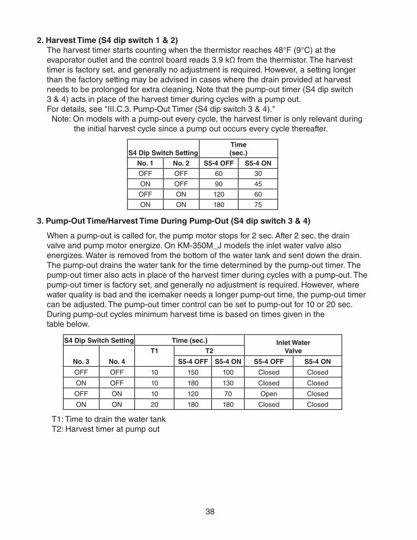
38
2. Harvest Time (S4 dip switch 1 & 2)The harvest timer starts counting when the thermistor reaches 48°F (9°C) at the evaporator outlet and the control board reads 3.9 kΩ from the thermistor. The harvest timer is factory set, and generally no adjustment is required. However, a setting longer than the factory setting may be advised in cases where the drain provided at harvest needs to be prolonged for extra cleaning. Note that the pump-out timer (S4 dip switch 3 & 4) acts in place of the harvest timer during cycles with a pump out. For details, see "III.C.3. Pump-Out Timer (S4 dip switch 3 & 4)."
Note: On models with a pump-out every cycle, the harvest timer is only relevant during the initial harvest cycle since a pump out occurs every cycle thereafter.
S4 Dip Switch SettingTime (sec.)
No. 1 No. 2 S5-4 OFF S5-4 ON
OFF OFF 60 30
ON OFF 90 45
OFF ON 120 60
ON ON 180 75
3. Pump-Out Time/Harvest Time During Pump-Out (S4 dip switch 3 & 4)
When a pump-out is called for, the pump motor stops for 2 sec. After 2 sec. the drainvalve and pump motor energize. On KM-350M_J models the inlet water valve also energizes. Water is removed from the bottom of the water tank and sent down the drain. The pump-out drains the water tank for the time determined by the pump-out timer. The pump-out timer also acts in place of the harvest timer during cycles with a pump-out. The pump-out timer is factory set, and generally no adjustment is required. However, where water quality is bad and the icemaker needs a longer pump-out time, the pump-out timer can be adjusted. The pump-out timer control can be set to pump-out for 10 or 20 sec. During pump-out cycles minimum harvest time is based on times given in thetable below.
S4 Dip Switch Setting Time (sec.) Inlet Water Valve
No. 3 No. 4
T1 T2
S5-4 OFF S5-4 ON S5-4 OFF S5-4 ON
OFF OFF 10 150 100 Closed Closed
ON OFF 10 180 130 Closed Closed
OFF ON 10 120 70 Open Closed
ON ON 20 180 180 Closed Closed
T1: Time to drain the water tankT2: Harvest timer at pump out

39
4. Pump-Out Frequency Control (S4 dip switch 5)The pump-out frequency control is factory set to drain the water tank every 10 cycles.Generally no adjustment is required. However, where water quality is bad and theicemaker needs a pump-out more often, the pump-out frequency can be adjusted. Thepump-out frequency control can be set to have a pump-out occur every cycle, or every10 cycles.
The first pump-out is dependent on S4 dip switch 5. See the table below.
S4 Dip Switch SettingPump-Out Frequency 1st Pump-Out
No. 5
OFF Every 10 cycles After 11th freeze cycle
ON Every cycle After 2nd freeze cycle
5. Harvest Pump Time (Harvest Assist) (S4 dip switch 6)
NOTICEFactory set for proper operation. Do not adjust. Adjustment outside of the factory default setting may result in damage to the appliance.
Harvest pump time (harvest assist) is only active when S4 dip switch 7 is in the "ON" position. In the factory default position, the harvest pump time (harvest assist) starts with 50 sec. left to go in harvest cycle (S4 dip switch 6) and after the thermistor reaches 48°F (9°C) at the evaporator outlet and the control board reads 3.9 kΩ from the thermistor. The harvest pump time (harvest assist) is factory set, and no adjustment is required.
S4 Dip Switch SettingHarvest Pump Time
(Harvest Assist)
No. 6 S5-4 OFF S5-4 ON
OFF 50 sec. 25 sec.
ON 25 sec. 15 sec.

40
6. Harvest Pump Time (Harvest Assist (S4 dip switch 7)
NOTICEFactory set for proper operation. Do not adjust. Adjustment outside of the factory default setting may result in damage to the appliance.
Depending on S4 dip switch 7 setting, the pump motor either stays off or is energized during the last seconds of the harvest cycle. When the pump motor is energized (S4 dip switch 7 on), water circulates over the evaporator. The harvest water valve is open during harvest for a maximum of 6 minutes or the length of harvest minus the harvest pump time value(S4 dip switch 6), whichever is shorter.
When S4 dip switch 7 is in the on position and harvest begins, 50 sec. before harvest termination, LED 4 turns off, inlet water valve Next, LED 3 turns on and control board K1 connector pin #4 (R) energizes, energizing the pump motor for the last seconds of harvest. Harvest pump time adjusted by S4 dip switch 1 & 2 and S5 dip switch 4 settings. Contact Technical Support before adjusted these settings.
S4 Dip Switch Setting Harvest Pump Time (sec.)
(Harvest Assist)No. 7
OFF 0
ON 50
7. Factory Use (S4 dip switch 8)Factory set for proper operation. Do not adjust. This must be left in the factory default position.
8. Freeze Timer (S4 dip switch 9 & 10)
NOTICEAdjust to proper specification, or the icemaker may not operate correctly.
The freeze timer setting determines the maximum allowed freeze time to prevent possible freeze-up issues. Upon termination of the freeze timer, the control board initiates the harvest cycle or pump-out cycle. After 2 consecutive freeze timer terminations, the control board shuts down the icemaker. In this case, see "II.I.3. Low Ice Production" for possible solutions. The freeze timer is factory set and no adjustment is required. Before changing this setting, contact Hoshizaki Technical Support at 1-800-233-1940 for recommendations.
S4 Dip Switch Setting Time (min.)No. 9 No. 10
OFF OFF 60
OFF ON 50
ON OFF 70
ON ON 75

41
9. Pump-Out Pump Motor Direction (S5 dip switch 1)
NOTICEDo not adjust. This must be left in the factory default position or the icemaker will not operate correctly.
The pump-out pump motor direction setting determines pump motor rotation during pump-out. On models with a drain valve pump motor rotation doesn't change at pump-out. Pump motor rotates in forward direction and drain valve is energized for pump-out. On models with a check valve, pump motor rotation reverses at pump-out. Pump motor rotates in reverse direction and opens check valve for pump-out.
S5 Dip Switch Setting
Pump-Out ComponentsNo. 1
OFF Pump Motor Forward Rotation and Drain Valve
ON Pump Motor Reverse Rotation and Check Valve
10. Refill Counter (S5 dip switch 2 and 3)
NOTICEDo not adjust. These must be left in the factory default position or the icemaker will not operate correctly.
S5 Dip Switch Setting Refill CounterNo. 2 No. 3
OFF OFF 0
OFF ON 1 refill
ON OFF 9 refills
ON ON 10 refills
11. Minimum Harvest Time (S5 dip switch 4)
NOTICEFactory set for proper operation. Do not adjust. Adjustment outside the factory default setting may result in damage to the appliance.
S5 Dip Switch Setting Minimum Harvest TimerNo. 4
OFF 120 sec.
ON 70 sec.

42
12. Anti-Slush (S5 dip switch 5)This dip switch setting provides anti-slush control during the freeze cycle. When the evaporator temperature reaches 36°F (2.2°C) the control board reads a 5.8 kΩ signal from the thermistor and de-energizes the water pump for 10 sec. to melt the ice slush and prevent the ice slush from blocking the water supply tubing, causing irregular freeze patterns.
NOTICEFactory set for proper operation. Do not adjust. Adjustment outside the factory default setting may result in damage to the appliance.
S5 Dip Switch Setting
Anti-SlushNo. 5
OFF Disabled
ON Enabled

43
IV. Refrigeration Circuit and Component Service Information
WARNING• This appliance should be diagnosed and repaired only by qualified service
personnel to reduce the risk of death, electric shock, serious injury, or fire.
• Move the control switch to the "OFF" position and turn off the power supply. Place the disconnect in the "OFF" position. Lockout/Tagout to prevent the power supply from being turned back on inadvertently.
• CHOKING HAZARD: Ensure all components, fasteners, and thumbscrews are securely in place after the icemaker is serviced. Make sure that none have fallen into the dispenser unit/ice storage bin.
• Make sure all food zones in the icemaker and dispenser unit/ice storage bin are clean after service.
A. Refrigeration Circuit Service Information
WARNING• Repairs requiring the refrigeration circuit to be opened must be performed by
properly trained and EPA-certified service personnel.
• Use an electronic leak detector or soap bubbles to check for leaks. Add a trace of refrigerant to the system (if using an electronic leak detector), and then raise the pressure using nitrogen gas (140 PSIG). Do not use R-404A as a mixture with pressurized air for leak testing.
NOTICE• Always recover the refrigerant and store it in an approved container. Do not
discharge the refrigerant into the atmosphere.
• Do not leave the system open for longer than 15 min. when replacing or servicing parts. The Polyol Ester (POE) oils used in R-404A applications can absorb moisture quickly. Therefore it is important to prevent moisture from entering the system when replacing or servicing parts.
• Always install a new drier every time the sealed refrigeration system is opened. Do not replace the drier until after all other repair or replacement has been made. Install the new drier with the arrow on the drier in the direction of the refrigerant flow.
• When brazing, protect the drier by using a wet cloth to prevent the drier from overheating. Do not allow the drier to exceed 250°F (121°C).
1. Refrigerant RecoveryThe icemaker is provided with refrigerant access valves. Using proper refrigerant practices, recover the refrigerant. Store the refrigerant in an approved container. Do not discharge the refrigerant into the atmosphere.

44
2. Brazing
WARNING• R-404A itself is not flammable at atmospheric pressure and temperatures up to
176°F (80°C).
• R-404A itself is not explosive or poisonous. However, when exposed to high temperatures (open flames), R-404A can be decomposed to form hydrofluoric acid and carbonyl fluoride both of which are hazardous.
• Do not use silver alloy or copper alloy containing arsenic.
1) Braze all fittings while purging with nitrogen gas flowing at a pressure of 3 to 4 PSIG.Note: Because the pipes in the evaporator case are specially coated to resist corrosion,
it is important to make connections outside the evaporator case when possible. If it is necessary to braze inside the evaporator case, use sandpaper to remove the coating from the brazing connections before unbrazing the components.
NOTICE• Always install a new drier every time the sealed refrigeration system is opened.
• Do not replace the drier until after all other repair or replacement has been made. Install the new drier with the arrow on the drier in the direction of the refrigerant flow.
• When brazing, protect the drier by using a wet cloth to prevent the drier from overheating. Do not allow the drier to exceed 250°F (121°C).
2) Use an electronic leak detector or soap bubbles to check for leaks. Add a trace of refrigerant to the system (if using an electronic leak detector), and then raise the pressure using nitrogen gas (140 PSIG). Do not use R-404A as a mixture with pressurized air for leak testing.
3. Evacuation and Recharge (R-404A)
1) Attach a vacuum pump to the system. Be sure to connect the charging hoses to both high and low-side refrigerant access valves.
IMPORTANTThe vacuum level and vacuum pump may be the same as those for current refrigerants. However, the rubber hose and gauge manifold to be used for evacuation and refrigerant charge should be exclusively for POE oils.
2) Turn on the vacuum pump. Open the gauge manifold valves. Never allow the oil in the vacuum pump to flow backwards.
3) Allow the vacuum pump to pull down to a 29.9" Hg vacuum. Evacuating period depends on pump capacity.
4) Close the low-side valve and high-side valve on the gauge manifold.

45
5) Disconnect the gauge manifold hose from the vacuum pump and attach it to a refrigerant service cylinder. Remember to loosen the connection and purge the air from the hose. For the required refrigerant charge, see the rating label inside the icemaker. Hoshizaki recommends only virgin refrigerant or reclaimed refrigerant which meets ARI Standard 700 (latest edition) be used.
6) A liquid charge is required when charging an R-404A system (to prevent fractionation). Place the service cylinder on the scales; if the service cylinder is not equipped with a dip tube, invert the service cylinder, then place it on the scales. Open the high-side valve on the gauge manifold.
7) Allow the system to charge with liquid until the proper charge weight is met.
8) If necessary, add any remaining charge to the system through the low-side. NOTICE! To prevent compressor damage, use a throttling valve or liquid dispensing device to add the remaining liquid charge through the low-side refrigerant access valve with the icemaker running.
9) Close the high and low-side gauge manifold valves, then disconnect the gauge manifold hoses.
10) Cap the refrigerant access valves to prevent a possible leak.

46
B. Component Service Information
NOTICEWhen replacing a component listed below, see the notes to help ensure proper operation.
Component Notes
Compressor 1 phase: Install a new start capacitor, run capacitor, and start relay.
Thermostatic Expansion Valves
• Attach the thermostatic expansion valve bulb to the suction line in the same location as the previous bulb.
• The bulb should be between the 10 and 2 o'clock positions on the tube.
• Secure the bulb with the clamp and holder, then insulate it.
Hot Gas ValvesLiquid Line Valves
• Replace the strainer if applicable.
• Use copper tube of the same diameter and length when replacing valve lines.
Fan Motors Install a new capacitor.
Pump Motor Install a new capacitor.
Thermistor • Attach the new thermistor to the suction line in the same location as the previous thermistor.
• The thermistor should be at the 12 o'clock position on the tube.
• Smoothly fill the recessed area of the thermistor holder with high thermal conductive type sealant. Hoshizaki America part number 4A0683-01 (Silicone Heat Sink Compound 10-8108 manufactured by GC Electronics), KE-4560 RTV (manufactured by ShinEtsu Silicones), or equivalent are recommended.
• Secure the thermistor with the holder, then insulate it.
• Be very careful to prevent damage to the leads.

47
C. Water Regulating Valve Adjustment (water-cooled model)The water regulating valve is factory set, and generally no adjustment is required. However, when necessary, adjust the water regulator using the following procedure.
1) Prepare a thermometer to check the condenser drain temperature. Attach a pressure gauge to the high-side line of the system.
2) 5 min. after a freeze cycle starts, confirm that the thermometer reads 104°F to 115°F (40°C to 46°C). If it does not, rotate the adjustment screw by using a flat blade screwdriver until the temperature is in the proper range. See Fig. 7. Next, check that the reference pressure is in the range indicated in the Head Pressure table in the Performance Data section. If it is not in the proper range, verify the refrigerant charge.
3) Check that the condenser drain temperature is stable.
Fig. 7
Adjustment Screw
CW – HigherCCW – Lower
Top View

48
V. Maintenance
The maintenance schedule below is a guideline. More frequent maintenance may berequired depending on water quality, the appliance's environment, and local sanitationregulations
WARNING• Only qualified service technicians should service the appliance.
• To reduce the risk of electric shock, do not touch the control switch or service switch with damp hands
• Before servicing: Move the control switch to the "OFF" position and turn off the power supply. Place the disconnect in the "OFF" position. Lockout/Tagout to prevent the power supply from being turned back on inadvertently.
• CHOKING HAZARD: Ensure all components, fasteners, and thumbscrews are securely in place after any maintenance is done to the icemaker. Make sure that none have fallen into the dispenser unit/ice storage bin.
Maintenance ScheduleFrequency Area Task
Daily Scoop Clean the ice scoop using a neutral cleaner. Rinse thoroughly after cleaning.
Bi-Weekly Air Filters Inspect. Wash with warm water and neutral cleaner if dirty.Monthly External Water
FiltersCheck for proper pressure and change if necessary.
Icemaker Exterior Wipe down with a clean, soft cloth. Use a damp cloth containing a neutral cleaner to wipe off oil or dirt build up. Clean any chlorine staining (rust colored spots) using a non-abrasive cleanser.
Underside of Icemaker and Top Kits; Bin Door and Snout
Wipe down with a clean cloth and warm water.
Yearly Icemaker and Dispenser Unit/Ice Storage Bin Liner
Clean and sanitize per the cleaning and sanitizing instructions provided in the instruction manual or maintenance label on the icemaker.
Water Supply Inlet Close the icemaker water supply line shut-off valve and drain the water system. Clean the water supply inlet screen.
Condenser Inspect. Clean if necessary by using a brush or vacuum cleaner. More frequent cleaning may be required depending on location.
Water Hoses Inspect the water hoses and clean/replace if necessary.

49
VI. Preparing the Appliance for Periods of Non-Use
NOTICE• When storing the appliance for an extended time or in sub-freezing temperatures,
follow the instructions below to prevent damage.
• To prevent damage to the water pump, do not operate the appliance with the control switch in the "WASH" position when the water tank is empty.
When the appliance is not used for two or three days under normal conditions, it is sufficient to move the control switch to the "OFF" position. When storing the appliance for an extended time or in sub-freezing temperatures, follow the instructions below.
1. Remove the water from the icemaker water line:
1) Turn off the power supply, then remove the front panel.
2) Close the icemaker water supply line shut-off valve and open the icemaker water supply line drain valve.
3) Allow the line to drain by gravity.
4) Attach a compressed air or carbon dioxide supply to the icemaker water supply line drain valve.
5) Make sure at least 3 min. have elapsed since you turned off the power supply. Make sure the control switch is in the "ICE" position. Replace the front panel in its correct position, then turn on the power supply.
6) Blow the icemaker water supply line out using the compressed air or carbon dioxide supply.
7) Close the icemaker water supply line drain valve.
2. Remove the water from the water tank:
1) Turn off the power supply, then remove the front panel.
2) Move the control switch to the "OFF" position.
3) Drain the water tank. Remove the base cover, then disconnect one end of the pump tubing to drain the water tank. See Fig. 8. After the water tank has drained, reconnect the pump tubing.
4) Replace the base cover (if applicable) and front panel in their correct positions.
5) Remove all ice from the dispensing unit/ice storage bin. Clean the storage bin liner using a neutral cleaner. Rinse thoroughly after cleaning.
Fig. 8
Disconnect This End of Pump Tubing to Drain Water Tank
Base Cover

50
3. On water-cooled model, remove the water from the water-cooled condenser:
1) Make sure the power supply is off, then remove the front panel and right side panel.
2) Close the condenser water supply line shut-off valve. If connected to a closed loop system, also close the condenser return line shut-off valve.
3) Open the condenser water supply line drain valve. If connected to a closed loop system, also open the condenser return line drain valve.
4) Attach a compressed air or carbon dioxide supply to the condenser water supply line drain valve.
5) Open the water regulating valve by using a screwdriver to pry up on the spring retainer underneath the spring. While holding the valve open, blow out the condenser using the compressed air or carbon dioxide supply until water stops coming out.
6) Close the drain valve(s).
7) Replace the right side panel and front panel in their correct positions.

51
VII. DisposalThe appliance contains refrigerant and must be disposed of in accordance with applicable national, state, and local codes and regulations. Refrigerant must be recovered by properly certified service personnel.

52
VIII. Technical InformationWe reserve the right to make changes in specifications and design without prior notice.
A. Specification and Performance Data SheetsPressure data is recorded at 5 min. into freezing cycle. The data not in bold should be used for reference only.
1. KM-350MAJ
Specification SheetAC SUPPLY VOLTAGE 115/60/1AMPERAGE 9.05 A (5 Min. Freeze AT 104°F / WT 80°F)MINIMUM CIRCUIT AMPACITY 15 AMAXIMUM FUSE SIZE 15 AELECTRIC & WATER CONSUMPTION 90/70°F 70/50°F ELECTRIC W (kWH/100 lbs.) 890 (5.42) 810 (3.99) WATER gal./24HR (gal./100 lbs.) 57 (14.5) 136 (27.8)ICE PRODUCTION PER CYCLE 10.5 lbs. (4.8 kg) 480 pcs.BIN CONTROL SYSTEM Ultra-Sonic SensorREFRIGERANT CHARGE R404A, 1 lb. 3.4 oz. (550g)
Performance Data Sheet
70/21 489 222 461 209 437 19880/27 468 212 424 192 407 18590/32 461 209 393 178 372 169
lbs./day kg./day 100/38 461 209 388 176 353 16070/2180/2790/32
watts 100/3870/21 136 0.52 113 0.43 103 0.3980/27 119 0.45 82 0.31 85 0.3290/32 113 0.43 57 0.22 54 0.20
gal./day m3/day 100/38 87 0.33 56 0.21 51 0.1970/2180/2790/32
min. 100/3870/2180/2790/32
min. 100/3870/21 233 16.4 249 17.5 278 19.680/27 245 17.2 270 19.0 304 21.490/32 249 17.5 287 20.2 320 22.5
PSIG kg/cm2G 100/38 257 18.1 295 20.7 350 24.670/21 58 4.1 59 4.1 60 4.280/27 58 4.1 59 4.2 60 4.290/32 59 4.1 60 4.2 61 4.3
PSIG kg/cm2G 100/38 59 4.1 60 4.2 62 4.4
5,700 BTU/h [AT 90ºF (32ºC) / WT 70ºF (21ºC)]TOTAL HEAT OF REJECTION FROM COMPRESSOR 1,000 BTU/h [AT 90ºF (32ºC) / WT 70ºF (21ºC)]
2.82.32.02.0
293131313.1
31343737
2.02.0
33363840
2.42.7
9319531010
WATER TEMP. (ºF/ºC)50/10 70/21 90/32
810828833852
833864890905
888
HARVEST CYCLE TIME
HEAD PRESSURE
SUCTION PRESSURE
TOTAL HEAT OF REJECTION FROM CONDENSER
APPROXIMATE ICE PRODUCTION PER 24 HR.
AMBIENT TEMP. (ºF/ºC)
APPROXIMATE ELECTRIC CONSUMPTION
APPROXIMATE WATER CONSUMPTION PER 24 HR.
FREEZING CYCLE TIME
2.92.82.4
ENG.F-011.1.0205

53
2. KM-350MWJ
Specification SheetAC SUPPLY VOLTAGE 115/60/1AMPERAGE 7.5 A ( 5 Min. Freeze AT 104°F / WT 80°F)MINIMUM CIRCUIT AMPACITY 15 AMAXIMUM FUSE SIZE 15 AELECTRIC & WATER CONSUMPTION 90/70°F 70/50°F ELECTRIC W (kWH/100 lbs.) 780 (4.90) 770 (4.47) WATER gal./24HR (gal./100 lbs.) 59 (15.5) 96 (23.2) WATER COOLED CONDENSER 415 (109) 139 (34)gal./24HR (gal./100 lbs.)ICE PRODUCTION PER CYCLE 10.5 lbs. (4.8 kg) 480pcs.BIN CONTROL SYSTEM Ultra-Sonic SensorREFRIGERANT CHARGE R404A, 0 lb. 11.6 oz. (330g)
Performance Data Sheet
70/21 414 188 405 184 390 17780/27 407 185 393 178 376 17190/32 405 184 383 174 366 166
lbs./day kg./day 100/38 401 182 379 172 351 15970/2180/2790/32
watts 100/3870/21 236 0.89 306 1.16 416 1.5780/27 289 1.09 398 1.51 516 1.9590/32 306 1.16 475 1.80 592 2.24
gal./day m3/day 100/38 417 1.58 502 1.90 699 2.6570/2180/2790/32
min. 100/3870/2180/2790/32
min. 100/3870/21 228 16.0 228 16.0 233 16.480/27 228 16.0 228 16.0 235 16.590/32 228 16.0 228 16.0 234 16.5
PSIG kg/cm2G 100/38 231 16.2 229 16.1 240 16.970/21 59 4.1 59 4.2 59 4.280/27 59 4.2 60 4.2 60 4.290/32 59 4.2 60 4.2 60 4.2
PSIG kg/cm2G 100/38 59 4.2 60 4.2 60 4.2
6,600 BTU/h [AT 90ºF (32ºC) / WT 70ºF (21ºC)]TOTAL HEAT OF REJECTION FROM COMPRESSOR 900 BTU/h [AT 90ºF (32ºC) / WT 70ºF (21ºC)]WATER FLOW FOR CONDENSER 27 gal./h [AT 100ºF (38ºC) / WT 90ºF (32ºC)]
2.1 2.0HEAD PRESSURE
SUCTION PRESSURE
TOTAL HEAT OF REJECTION FROM CONDENSER
2.4
HARVEST CYCLE TIME 2.8 2.6 2.52.7 2.4 2.32.6 2.2 2.1
APPROXIMATE WATER CONSUMPTION PER 24 HR.
FREEZING CYCLE TIME 34 35 3635 36 3735 37 38
APPROXIMATE ELECTRIC CONSUMPTION
770 773 774772 777 776773 780 780
APPROXIMATE ICE PRODUCTION PER 24 HR.
AMBIENT TEMP. (ºF/ºC)
WATER TEMP. (ºF/ºC)50/10 70/21 90/32
38
780 780
35 37
772
ENG.F-011.1.0205

54
3. KM-520MAJ
Specification SheetAC SUPPLY VOLTAGE 115/60/1AMPERAGE 10.6 A ( 5 Min. Freeze AT 104°F / WT 80°F)MINIMUM CIRCUIT AMPACITY 20 AMAXIMUM FUSE SIZE 20 AELECTRIC & WATER CONSUMPTION 90/70°F 70/50°F ELECTRIC W (kWH/100 lbs.) 940 (4.68) 840 (3.64) WATER gal./24HR (gal./100 lbs.) 71 (14.7) 180 (32.4)ICE PRODUCTION PER CYCLE 10.3 lbs. (4.7 kg) 480pcs.BIN CONTROL SYSTEM Ultra-Sonic SensorREFRIGERANT CHARGE R404A, 1 lb. 10.8 oz. (760g)
Performance Data Sheet
70/21 556 252 534 242 497 22680/27 539 245 505 229 465 21190/32 534 242 480 218 441 200
lbs./day kg./day 100/38 524 238 471 214 405 18470/2180/2790/32
watts 100/3870/21 180 0.68 148 0.56 133 0.5080/27 156 0.59 106 0.40 107 0.4190/32 148 0.56 71 0.27 65 0.25
gal./day m3/day 100/38 112 0.42 69 0.26 59 0.2370/2180/2790/32
min. 100/3870/2180/2790/32
min. 100/3870/21 200 14.1 218 15.4 248 17.480/27 214 15.1 243 17.1 275 19.390/32 218 15.4 263 18.5 295 20.7
PSIG kg/cm2G 100/38 226 15.9 270 19.0 324 22.870/21 46 3.2 49 3.4 52 3.680/27 48 3.4 52 3.7 55 3.990/32 49 3.4 55 3.9 58 4.1
PSIG kg/cm2G 100/38 49 3.5 56 3.9 61 4.3
6,600 BTU/h [AT 90ºF (32ºC) / WT 70ºF (21ºC)]TOTAL HEAT OF REJECTION FROM COMPRESSOR 1,100 BTU/h [AT 90ºF (32ºC) / WT 70ºF (21ºC)]
944 970
26 30 35
867
90/32APPROXIMATE ICE PRODUCTION PER 24 HR.
AMBIENT TEMP. (ºF/ºC)
WATER TEMP. (ºF/ºC)50/10 70/21
APPROXIMATE ELECTRIC CONSUMPTION
840 869 891862 908 919869 940 956
APPROXIMATE WATER CONSUMPTION PER 24 HR.
FREEZING CYCLE TIME 24 25 2825 27 3125 29 32
HARVEST CYCLE TIME 3.4 3.0 2.93.1 2.4 2.63.0 2.0 2.0
2.0 2.0HEAD PRESSURE
SUCTION PRESSURE
TOTAL HEAT OF REJECTION FROM CONDENSER
2.6
ENG.F-011.1.0205

55
4. KM-520MWJ
Specification SheetAC SUPPLY VOLTAGE 115/60/1AMPERAGE 8.45 A ( 5 Min. Freeze AT 104°F / WT 80°F)MINIMUM CIRCUIT AMPACITY 20 AMAXIMUM FUSE SIZE 20 AELECTRIC & WATER CONSUMPTION 90/70°F 70/50°F ELECTRIC W (kWH/100 lbs.) 860 (4.65) 880 (4.45) WATER gal./24HR (gal./100 lbs.) 66 (14.8) 114 (24.1) WATER COOLED CONDENSER 333 (75) 149 (31)gal./24HR (gal./100 lbs.)ICE PRODUCTION PER CYCLE 10.7 lbs. (4.8 kg) 480pcs.BIN CONTROL SYSTEM Ultra-Sonic SensorREFRIGERANT CHARGE R404A, 0 lb. 12.7 oz. (360g)
Performance Data Sheet
70/21 474 215 465 211 451 20480/27 467 212 454 206 438 19990/32 465 211 444 201 428 194
lbs./day kg./day 100/38 462 209 440 200 414 18870/2180/2790/32
watts 100/3870/21 263 1.00 303 1.15 376 1.4280/27 294 1.11 355 1.34 438 1.6690/32 303 1.15 399 1.51 479 1.81
gal./day m3/day 100/38 371 1.40 418 1.58 552 2.0970/2180/2790/32
min. 100/3870/2180/2790/32
min. 100/3870/21 284 20.0 284 19.9 282 19.880/27 284 20.0 283 19.9 280 19.790/32 284 19.9 283 19.9 280 19.7
PSIG kg/cm2G 100/38 283 19.9 282 19.9 278 19.570/21 54 3.8 54 3.8 55 3.980/27 54 3.8 55 3.8 56 3.990/32 54 3.8 55 3.9 56 3.9
PSIG kg/cm2G 100/38 55 3.8 55 3.9 57 4.0
6,300 BTU/h [AT 90ºF (32ºC) / WT 70ºF (21ºC)]TOTAL HEAT OF REJECTION FROM COMPRESSOR 2,100 BTU/h [AT 90ºF (32ºC) / WT 70ºF (21ºC)]WATER FLOW FOR CONDENSER 20 gal./h [AT 100ºF (38ºC) / WT 90ºF (32ºC)]
2.0 2.0HEAD PRESSURE
SUCTION PRESSURE
TOTAL HEAT OF REJECTION FROM CONDENSER
2.5
HARVEST CYCLE TIME 3.1 2.8 2.72.9 2.4 2.52.8 2.0 2.0
APPROXIMATE WATER CONSUMPTION PER 24 HR.
FREEZING CYCLE TIME 30 30 3130 31 3230 32 33
APPROXIMATE ELECTRIC CONSUMPTION
880 874 864876 866 856874 860 850
APPROXIMATE ICE PRODUCTION PER 24 HR.
AMBIENT TEMP. (ºF/ºC)
WATER TEMP. (ºF/ºC)50/10 70/21 90/32
33
858 840
30 32
872
ENG.F-011.1.0205

56
5. KM-520MRJ with URC-5FAC SUPPLY VOLTAGE 115/60/1AMPERAGE 12.05 A ( 5 Min. Freeze AT 104°F / WT 80°F)MINIMUM CIRCUIT AMPACITY 20 AMAXIMUM FUSE SIZE 20 AELECTRIC & WATER CONSUMPTION 90/70°F 70/50°F ELECTRIC W (kWH/100 lbs.) 990 (4.80) 920 (4.05) WATER gal./24HR (gal./100 lbs.) 67 (13.6) 173 (31.6)ICE PRODUCTION PER CYCLE 10.6 lbs. (4.8 kg) 480pcs.BIN CONTROL SYSTEM Ultra-Sonic SensorREFRIGERANT CHARGE TOTAL R404A, 4 lb. 2.7 oz. (1890g)
ICEMAKER, 2 lb. 4.7 oz. (1040g)CONDENSER, 1 lb. 14 oz. (850g)
Performance Data Sheet
70/21 547 248 532 241 507 23080/27 535 243 512 232 484 22090/32 532 241 495 225 468 212
lbs./day kg./day 100/38 525 238 489 222 444 20170/2180/2790/32
watts 100/3870/21 173 0.65 142 0.54 129 0.4980/27 149 0.57 101 0.38 105 0.4090/32 142 0.54 67 0.25 64 0.24
gal./day m3/day 100/38 108 0.41 66 0.25 60 0.2370/2180/2790/32
min. 100/3870/2180/2790/32
min. 100/3870/21 207 14.6 223 15.6 249 17.580/27 219 15.4 243 17.1 272 19.190/32 223 15.6 260 18.3 289 20.3
PSIG kg/cm2G 100/38 230 16.1 267 18.8 315 22.170/21 50 3.5 50 3.5 53 3.780/27 50 3.5 51 3.6 55 3.990/32 50 3.5 51 3.6 55 3.8
PSIG kg/cm2G 100/38 52 3.6 52 3.6 58 4.1
6,200 BTU/h [AT 90ºF (32ºC) / WT 70ºF (21ºC)]TOTAL HEAT OF REJECTION FROM COMPRESSOR 1,000 BTU/h [AT 90ºF (32ºC) / WT 70ºF (21ºC)]CONDENSER VOLUME 43 CU. IN. URC-5F
34
APPROXIMATE ELECTRIC CONSUMPTION
920 941 963936 968 986
APPROXIMATE ICE PRODUCTION PER 24 HR.
AMBIENT TEMP. (ºF/ºC)
WATER TEMP. (ºF/ºC)50/10 70/21 90/32
941 990 1011943 995 1030
APPROXIMATE WATER CONSUMPTION PER 24 HR.
FREEZING CYCLE TIME 25 26 2826 28 3026 29 3226 30
HARVEST CYCLE TIME 3.4 3.0 2.93.1 2.5 2.63.0 2.0 2.0
TOTAL HEAT OF REJECTION FROM CONDENSER
2.6 2.0 2.0HEAD PRESSURE
SUCTION PRESSURE
ENG.F-011.1.0205

57
6. KM-660MAJ
Specification SheetAC SUPPLY VOLTAGE 115/60/1AMPERAGE 15.2 A ( 5 Min. Freeze AT 104°F / WT 80°F)MINIMUM CIRCUIT AMPACITY 20 AMAXIMUM FUSE SIZE 20 AELECTRIC & WATER CONSUMPTION 90/70°F 70/50°F ELECTRIC W (kWH/100 lbs.) 1320 (5.12) 1200 (4.34) WATER gal./24HR (gal./100 lbs.) 91 (14.8) 204 (30.6)ICE PRODUCTION PER CYCLE 10.7 lbs. (4.8 kg) 480pcs.BIN CONTROL SYSTEM Ultra-Sonic SensorREFRIGERANT CHARGE R404A, 1 lb. 9.8 oz. (730g)
Performance Data Sheet
70/21 665 301 650 295 627 28580/27 654 297 632 287 607 27590/32 650 295 617 280 591 268
lbs./day kg./day 100/38 645 292 611 277 569 25870/2180/2790/32
watts 100/3870/21 204 0.77 171 0.65 157 0.5980/27 178 0.68 127 0.48 131 0.5090/32 171 0.65 91 0.35 87 0.33
gal./day m3/day 100/38 134 0.51 90 0.34 84 0.3270/2180/2790/32
min. 100/3870/2180/2790/32
min. 100/3870/21 212 14.9 232 16.3 264 18.580/27 227 16.0 257 18.1 292 20.690/32 232 16.3 279 19.6 313 22.0
PSIG kg/cm2G 100/38 240 16.9 287 20.2 345 24.370/21 37 2.6 39 2.8 46 3.280/27 39 2.7 42 3.0 51 3.690/32 39 2.8 45 3.2 53 3.7
PSIG kg/cm2G 100/38 42 2.9 47 3.3 60 4.2
8,000 BTU/h [AT 90ºF (32ºC) / WT 70ºF (21ºC)]TOTAL HEAT OF REJECTION FROM COMPRESSOR 1,500 BTU/h [AT 90ºF (32ºC) / WT 70ºF (21ºC)]
APPROXIMATE ELECTRIC CONSUMPTION
1200 1235 12781227 1281 1321
APPROXIMATE ICE PRODUCTION PER 24 HR.
AMBIENT TEMP. (ºF/ºC)
WATER TEMP. (ºF/ºC)50/10 70/21 90/32
1235 1320 13621242 1330 1400
APPROXIMATE WATER CONSUMPTION PER 24 HR.
FREEZING CYCLE TIME 20 21 2321 22 2421 24 2521 24 27
HARVEST CYCLE TIME 3.4 3.0 2.83.1 2.43.0 2.0 2.0
2.5
TOTAL HEAT OF REJECTION FROM CONDENSER
2.5 2.0 2.0HEAD PRESSURE
SUCTION PRESSURE
ENG.F-011.1.0205

58
7. KM-660MWJ
DATA PENDING

59
8. KM-660MRJ with URC-5F
Specification SheetAC SUPPLY VOLTAGE 115/60/1AMPERAGE 16.1 A ( 5 Min. Freeze AT 104°F / WT 80°F)MINIMUM CIRCUIT AMPACITY 20 AMAXIMUM FUSE SIZE 20 AELECTRIC & WATER CONSUMPTION 90/70°F 70/50°F ELECTRIC W (kWH/100 lbs.) 1400 (5.60) 1270 (4.72) WATER gal./24HR (gal./100 lbs.) 88 (14.7) 213 (32.9)ICE PRODUCTION PER CYCLE 10.4 lbs. (4.7 kg) 480pcs.BIN CONTROL SYSTEM Ultra-Sonic SensorREFRIGERANT CHARGE TOTAL R404A, 4 lb. 2.7 oz. (1890g)
ICEMAKER, 2 lb. 4.7 oz. (1040g)CONDENSER, 1 lb. 14 oz. (850g)
Performance Data Sheet
70/21 646 293 633 287 612 27780/27 636 289 616 279 592 26990/32 633 287 602 273 578 262
lbs./day kg./day 100/38 628 285 596 270 557 25370/2180/2790/32
watts 100/3870/21 213 0.80 176 0.67 162 0.6180/27 185 0.70 128 0.49 134 0.5190/32 176 0.67 88 0.33 85 0.32
gal./day m3/day 100/38 136 0.52 87 0.33 82 0.3170/2180/2790/32
min. 100/3870/2180/2790/32
min. 100/3870/21 215 15.1 232 16.3 260 18.380/27 228 16.0 254 17.9 285 20.090/32 232 16.3 273 19.2 303 21.3
PSIG kg/cm2G 100/38 239 16.8 280 19.7 330 23.270/21 40 2.8 41 2.9 44 3.180/27 41 2.9 43 3.1 46 3.290/32 41 2.9 45 3.2 48 3.3
PSIG kg/cm2G 100/38 42 3.0 46 3.2 50 3.5
8,100 BTU/h [AT 90ºF (32ºC) / WT 70ºF (21ºC)]TOTAL HEAT OF REJECTION FROM COMPRESSOR 1,500 BTU/h [AT 90ºF (32ºC) / WT 70ºF (21ºC)]CONDENSER VOLUME 43 CU. IN. URC-5F
26
APPROXIMATE ICE PRODUCTION PER 24 HR.
AMBIENT TEMP. (ºF/ºC)
WATER TEMP. (ºF/ºC)50/10 70/21 90/32
APPROXIMATE ELECTRIC CONSUMPTION
1270 1308 13591299 1358 14091308 1400 14521318 1412 1500
APPROXIMATE WATER CONSUMPTION PER 24 HR.
FREEZING CYCLE TIME 20 21 2220 22 2421 23 2521 24
HARVEST CYCLE TIME 3.5 3.0 2.93.1 2.5 2.63.0 2.0 2.0
TOTAL HEAT OF REJECTION FROM CONDENSER
2.6 2.0 2.0HEAD PRESSURE
SUCTION PRESSURE
ENG.F-011.1.0205

60
B. Wiring Diagram
1. KM-350M_J, KM-520M_J, KM-660M_J
115/
60/1
AB
BR
.C
OM
PO
NE
NT
NA
ME
X10
CR
AN
KC
AS
E H
EA
TER
RE
LAY
S4
DIP
SW
ITC
H S
ETT
ING
SM
OD
EL
12
34
56
78
910
KM
-350
M_J
OFF
ON
ON
OFF
ON
OFF
ON
K
M-5
20M
_JO
FFO
FFK
M-6
60M
_J
S5
DIP
SW
ITC
H S
ETT
ING
SM
OD
EL
12
34
5K
M-3
50M
_JO
FFO
NK
M-5
20M
_JK
M-6
20M
_J CA
PA
CIT
OR
TA
BLE
MO
DE
LS
TAR
T C
AP
.R
UN
CA
P.
KM
-350
M_J
243-
292M
FD35
MFD
KM
-520
M_J
243-
292M
FD35
MFD
KM
-660
M_J
243-
292M
FD40
MFD
(BK
)
R
MO
DE
SW
ITC
H
O
3 C
LEA
N
5
4 IC
E1
ICE2
6 C
LEA
N
CO
MP
10.5
VA
CC
ON
TRO
LTR
AN
SFO
RM
ER
115V
AC
(R)
K2K1
678910
INLE
TW
ATE
RV
ALV
E HI-P
RE
SS
. SW
ITC
H
P
P
12345 321
(R)
BK
FUS
E10
A
W
VP
BK
R
O
BK
NG
ND
R
W
P
(Y)
LIQ
.LI
NE
VA
LVE
BK
(R) W
CA
P.
FAN
(BK
)FIE
LDW
IRIN
G (W)
(BK
)
(BK
) W
W
WH
ITE
WH
ITE
V
O
R
BK
BR
CA
P.
5MFD
BR
FAN(B
K) (W
)
BK
BK
AIR
-CO
OLE
D M
OD
EL
CO
MC
OM
VV
W
FIE
LDW
IRIN
GW
W
W
V
L
P
BK
P
BK
CR
AN
KC
AS
EH
EA
TER
RE
MO
TE M
OD
EL
BK
46 1
0
W
WW
52 1S
R
C
BK
CO
MP
RE
SS
OR
RE
LAY
RR
WOW
W W
STA
RT
CA
P.
(SE
E T
AB
LE)
STA
RT
RE
LAY
RU
NC
AP
.(S
EE
TAB
LE)
GY
R
R RR
R
75
312
46
8
X10
GY
GY
GY
GY
V
V V
ON
13
PU
MP
2 O
FF
CO
NTR
OL
SW
ITC
H W
WW
BK
(BR
)(B
R)
W/B
U
R
W/R
W/B
UV
GY"S"
"R"
V
BK
BK
BK
BK
W(B
R)
PU
MP
GN
D(B
K)
(GR
)
(R)
CA
P.
5.5M
FD
W
(DB
U)
R
R
V
P
P
P
P
BLA
CK
RE
D
WH
ITE
(R)
BK
(BK
)
R(O)
(O)
1 2 3
FLO
AT
SW
ITC
H
THE
RM
ISTO
R
321321
K5
K3
CO
NTR
OL
BO
AR
D K4
ULT
RA
SO
NIC
BIN
CO
NTR
OL
BIN
CO
NTR
OL
SE
NS
OR
21
321
W
W(B
K)
(BK
)
K10
1K
103
R
WIR
E C
OLO
R C
OD
EB
K
BLA
CK
BR
B
RO
WN
DB
U
DA
RK
BLU
EG
R
GR
EE
NG
Y
GR
AY
LBU
LI
GH
T B
LUE
O
OR
AN
GE
P
PIN
KR
R
ED
V
VIO
LET
W
WH
ITE
Y
YE
LLO
WW
/BK
WH
ITE
/BLA
CK
W/B
R W
HIT
E/B
RO
WN
W/B
U W
HIT
E/B
LUE
W/O
W
HIT
E/O
RA
NG
EW
/R
WH
ITE
/RE
D
BK
BK
BK
W
HO
TG
AS
VA
LVE
WA
TER
DR
AIN
VA
LVE
WA
TER
BY
PA
SS
VA
LVE
R
V
V
R
GY
W/B
U
W
1 2B
LAC
KK
9V
RR R
RY
YY
W/R
W/R
W/R
W/R
BK
W
W/R
BK
BK
BK
R
O
"C"R
W
RY
(R)
(Y)
R
P
BK
RR
R R
R
WV
BK
Y
Y
(R)
(R)
5VD
C
2VD
C
5VD
C
115V
AC
10.5
VA
C
5VD
C
BIN
CO
NTR
OLL
ER
(BK
)*
* H
igh-
Pre
ssur
e S
witc
h
Wat
er-C
oole
d M
odel
Air
and
Rem
ote
Mod
els
Cut
-out
384±
22 P
SIG
412±
22 P
SIG
Cut
-in
284±
22 P
SIG
327±
22 P
SIG
00