Service Instructions - MICO...MICO, Inc. (2) Form No. 81-466-002 Revised 2019-11-25 FIGURE 1 FIGURE...
8
Form No. 81-466-002 Revised 2021-01-18 (1) MICO, Inc. TANDEM MODULATING VALVE (spool design) Service Instructions TABLE 1 (Specifications) Complete Unit Model Number Valve Assembly Number Repair Kit Number Brake Pressure Setting Complete Unit Model Number Valve Assembly Number Repair Kit Number Brake Pressure Setting bar (PSI) bar (PSI) 03-466-201 (BF) 03-466-202 (HO) 03-466-203 (BF) 03-466-204 (HO) 03-466-206 (HO) 03-466-208 (HO) 03-466-210 (HO) 03-466-212 (HO) 03-466-216 (HO) 06-466-195 (HO) 06-466-200 (HO) 06-466-201 (HO) 06-466-202 (HO) 06-466-204 (HO) 06-466-206 (HO) 06-466-207 (HO) 06-466-208 (HO) 06-466-209 (HO) 06-466-210 (HO) 06-466-213 (HO) 06-466-214 (HO) 06-466-216 (HO) 06-466-218 (HO) 06-466-220 (HO) 06-466-222 (HO) 06-466-227 (HO) 06-466-228 (HO) 06-466-229 (HO) 06-466-230 (HO) 06-466-231 (HO) 06-466-232 (HO) 06-466-233 (HO) 06-466-234 (HO) 06-466-235 (HO) 06-466-236 (HO) 06-466-237 (HO) 06-466-238 (HO) 06-466-239 (HO) 06-466-240 (HO) 06-466-241 (HO) 06-466-244 (HO) 06-466-245 (HO) 06-466-246 (HO) 06-466-248 (HO) 06-466-250 (HO) 06-466-252 (HO) 06-466-253 (HO) 06-466-258 (HO) 06-466-259 (HO) 06-466-260 (HO) 06-466-262 (HO) 06-466-263 (HO) 06-466-264 (HO) 06-466-266 (HO) 06-466-268 (HO) 20-100-798 20-100-555 20-100-843 20-100-587 20-100-583 20-100-667 n/a 20-100-808 20-100-833 20-100-537 20-100-580 20-100-574 20-100-536 20-100-792 20-100-522 20-100-522 20-100-574 20-100-723 20-100-537 20-100-806 20-100-663 20-100-554 20-100-537 20-100-522 20-100-522 20-100-840 20-100-613 20-100-839 20-100-511 20-100-806 20-100-583 20-100-849 20-100-593 20-100-839 20-100-595 20-100-522 20-100-609 20-100-663 20-100-613 20-100-790 20-100-628 20-100-895 20-100-688 20-100-676 20-100-678 n/a 20-100-806 20-100-722 20-200-023 20-100-723 20-100-724 20-100-806 20-100-725 20-100-726 20-100-725 06-400-257 06-400-152 06-400-257 06-400-152 06-400-152 06-400-152 06-400-152 06-400-152 06-400-152 06-400-152 06-400-152 06-400-152 06-400-152 06-400-152 06-400-152 06-400-152 06-400-152 06-400-152 06-400-152 06-400-152 06-400-152 06-400-152 06-400-152 06-400-152 06-400-152 06-400-152 06-400-152 06-400-152 06-400-152 06-400-152 06-400-152 06-400-152 06-400-152 06-400-152 06-400-152 06-400-152 06-400-152 06-400-152 06-400-152 06-400-152 06-400-152 06-400-152 06-400-152 06-400-152 06-400-152 06-400-152 06-400-152 06-400-152 06-400-152 06-400-152 06-400-152 06-400-152 06-400-152 06-400-152 06-400-152 144.8 ± 4.8 (2100 ± 70) 27.6 ± 3.5 (400 ± 50) 158.6 ± 4.8 (2300 ± 70) 137.9 ± 6.9 (2000 ± 100) 44.8 ± 3.5 (650 ± 50) 103.4 ± 5.2 (1500 ± 75) 43.1 ± 1.7 (625 ± 25) 131.0 ± 6.9 (1900 ± 100) 62.1 ± 5.2 (900 ± 75) 69.0 ± 5.2 (1000 ± 75) 82.7 ± 5.2 (1200 ± 75) 137.9 ± 6.9 (2000 ± 100) 151.7 ± 6.9 (2200 ± 100) 112.0 ± 3.5 (1625 ± 50) 103.4 ± 5.2 (1500 ± 75) 103.4 ± 5.2 (1500 ± 75) 137.9 ± 6.9 (2000 ± 100) 103.4 ± 5.2 (1500 ± 75) 69.0 ± 5.2 (1000 ± 75) 34.5 ± 3.5 (500 ± 75) 89.6 ± 5.2 (1300 ± 75) 41.4 ± 5.2 (600 ± 75) 69.0 ± 5.2 (1000 ± 75) 103.4 ± 5.2 (1500 ± 75) 103.4 ± 5.2 (1500 ± 75) 158.6 ± 6.9 (2300 ± 100) 53.4 ± 3.5 (775 ± 50) 120.7 ± 6.9 (1750 ± 100) 41.4 ± 5.2 (600 ± 75) 34.5 ± 3.5 (500 ± 50) 44.8 ± 3.5 (650 ± 50) 69.0 ± 3.5 (1000 ± 50) 27.6 ± 3.5 (400 ± 50) 120.7 ± 6.9 (1750 ± 100) 124.1 ± 6.9 (1750 ± 100) 103.4 ± 5.2 (1500 ± 75) 55.2 ± 5.2 (800 ± 75) 89.6 ± 5.2 (1300 ± 75) 53.4 ± 3.5 (775 ± 50) 44.8 ± 3.5 (650 ± 50) 48.3 ± 3.5 (700 ± 50) 48.3 ± 3.5 (700 ± 50) 103.4 ± 5.2 (1500 ± 75) 44.8 ± 2.4 (650 ± 35) 124.1 ± 6.9 (1800 ± 100) 69.0 ± 3.5 (1000 ± 50) 34.5 ± 3.5 (500 ± 50) 151.7 ± 6.9 (2200 ± 100) 55.2 ± 3.5 (800 ± 50) 103.4 ± 5.2 (1500 ± 75) 137.9 ± 6.9 (2000 ± 100) 34.5 ± 3.5 (500 ± 50) 69.0 ± 5.2 (1000 ± 75) 41.4 ± 5.2 (600 ± 75) 69.0 ± 5.2 (1000 ± 75) 06-466-270 (HO) 06-466-276 (HO) 06-466-280 (HO) 06-466-282 (HO) 06-466-284 (HO) 06-466-285 (HO) 06-466-286 (HO) 06-466-287 (HO) 06-466-288 (HO) 06-466-290 (HO) 06-466-292 (HO) 06-466-295 (HO) 06-466-296 (HO) 06-466-297 (HO) 06-466-298 (HO) 06-466-299 (HO) 06-466-301 (HO) 06-466-303 (HO) 06-466-315 (HO) 06-466-316 (HO) 06-466-354 (HO) 06-466-358 (HO) 06-466-387 (HO) 06-466-395 (HO) 06-466-409 (HO) 06-466-425 (HO) 06-466-429 (HO) 06-466-430 (HO) 06-466-447 (HO) 06-466-473 (HO) 06-466-488 (HO) 06-466-536 (HO) 06-466-559 (HO) 06-466-583 (HO) 06-466-597 (HO) 06-466-601 (HO) 06-466-614 (HO) 06-466-916 (HO) 06-466-919 (HO) 06-466-939 (HO) 20-100-749 (HO) 20-100-801 (HO) 20-100-808 (HO) 20-100-833 (HO) 20-100-930 (HO) 20-100-952 (HO) 4071010660 (HO) 4071010670 (HO) 20-100-728 20-200-277 20-100-789 20-100-522 20-100-574 20-100-522 20-100-541 20-100-887 20-100-522 20-100-574 20-100-537 20-100-806 20-100-522 20-100-805 n/a 20-100-782 20-100-790 20-200-011 20-200-082 20-200-023 20-100-849 20-200-277 20-100-536 20-200-252 20-100-895 20-100-593 20-100-574 20-100-725 20-100-900 20-200-096 20-100-964 20-200-132 20-100-613 20-200-173 20-200-276 20-200-012 20-200-309 20-100-535 20-100-900 n/a n/a n/a n/a n/a n/a n/a 4071010682 4071010672 06-400-152 06-400-152 06-400-152 06-400-152 06-400-152 06-400-152 06-400-152 06-400-152 06-400-152 06-400-152 06-400-152 06-400-152 06-400-152 06-400-152 06-400-152 06-400-152 06-400-152 06-400-152 06-400-152 06-400-152 06-400-152 06-400-152 06-400-152 06-400-152 06-400-152 06-400-152 06-400-152 06-400-152 06-400-152 06-400-152 06-400-152 06-400-152 06-400-152 06-400-152 06-400-152 06-400-152 06-400-152 06-400-152 06-400-152 06-400-152 06-400-152 06-400-152 06-400-152 06-400-152 06-400-152 06-400-152 06-400-152 06-400-152 53.4 ± 3.5 (775 ± 50 37.9 ± 3.5 (550 ± 50) 34.5 ± 2.1 (500 ± 30) 103.4 ± 5.2 (1500 ± 75) 137.9 ± 6.9 (2000 ± 100) 103.4 ± 5.2 (1500 ± 75) 51.7 ± 5.2 (750 ± 75) 103.4 ± 5.2 (1500 ± 75) 103.4 ± 5.2 (1500 ± 75) 137.9 ± 6.9 (2000 ± 100) 69.0 ± 5.2 (1000 ± 75) 34.5 ± 3.5 (500 ± 50) 103.4 ± 5.2 (1500 ± 75) 158.6 ± 6.9 (2300 ± 100) 158.6 ± 6.9 (2300 ± 100) 51.7 ± 5.2 (750 ± 75) 44.8 ± 3.5 (650 ± 50) 34.5 ± 3.5 (500 ± 50) 26.2 ± 1.7 (380 ± 25) 55.2 ± 3.5 (800 ± 50) 69.0 ± 3.5 (1000 ± 50) 37.9 ± 3.5 (550 ± 50) 151.7 ± 6.9 (2200 ± 100) 151.7 ± 6.9 (2200 ± 100) 48.3 ± 3.5 (700 ± 50) 27.6 ± 3.5 (400 ± 50) 137.9 ± 6.9 (2000 ± 100) 69.0 ± 5.2 (1000 ± 75) 59.0 ± 2.0 (855 ± 30) 117.2 ± 3.5 (1700 ± 50) 82.7 ± 5.2 (1200 ± 75) 27.6 ± 1.7 (400 ± 25) 53.4 ± 3.5 (775 ± 50) 65.5 ± 3.5 (950 ± 50) 103.4 ± 5.2 (1500 ± 75) 103.4 ± 5.2 (1500 ± 75) 137.9 ± 6.9 (2000 ± 100) 120.7 ± 6.9 (1750 ± 100) 59.0 ± 2.1 (855 ± 30) 37.9 ± 3.5 (550 ± 50) 91.4 ± 3.5 (1325 ± 50) 179.3 ± 6.9 (2600 ± 100) 131.0 ± 6.9 (1900 ± 100) 62.1 ± 5.2 (900 ± 75) 65.5 ± 3.5 (950 ± 50) 82.7 ± 5.2 (1200 ± 75) 155.1 ± 6.9 (2250 ± 100) 103.4 ± 6.9 (1500 ± 100) HO = Mineral Base Hydraulic Oil BF = Brake Fluid NOTE: If your product number is not listed, please contact MICO, Inc. for information.
Transcript of Service Instructions - MICO...MICO, Inc. (2) Form No. 81-466-002 Revised 2019-11-25 FIGURE 1 FIGURE...

Form No. 81-466-002 Revised 2021-01-18 (1) MICO, Inc.
TANDEMMODULATING VALVE
(spool design)
Service Instructions
TABLE 1 (Specifications)
Complete Unit Model
Number
Valve Assembly Number
Repair Kit
Number
Brake Pressure Setting
Complete Unit Model
Number
Valve Assembly Number
Repair Kit
Number
Brake Pressure Setting
bar (PSI) bar (PSI)03-466-201 (BF)03-466-202 (HO)03-466-203 (BF)03-466-204 (HO)03-466-206 (HO)03-466-208 (HO)03-466-210 (HO)03-466-212 (HO)03-466-216 (HO)06-466-195 (HO)06-466-200 (HO)06-466-201 (HO)06-466-202 (HO)06-466-204 (HO)06-466-206 (HO)06-466-207 (HO)06-466-208 (HO)06-466-209 (HO)06-466-210 (HO)06-466-213 (HO)06-466-214 (HO)06-466-216 (HO)06-466-218 (HO)06-466-220 (HO)06-466-222 (HO)06-466-227 (HO)06-466-228 (HO)06-466-229 (HO)06-466-230 (HO)06-466-231 (HO)06-466-232 (HO)06-466-233 (HO)06-466-234 (HO)06-466-235 (HO)06-466-236 (HO)06-466-237 (HO)06-466-238 (HO)06-466-239 (HO)06-466-240 (HO)06-466-241 (HO)06-466-244 (HO) 06-466-245 (HO) 06-466-246 (HO)06-466-248 (HO)06-466-250 (HO)06-466-252 (HO)06-466-253 (HO)06-466-258 (HO)06-466-259 (HO)06-466-260 (HO)06-466-262 (HO)06-466-263 (HO)06-466-264 (HO)06-466-266 (HO)06-466-268 (HO)
20-100-79820-100-55520-100-84320-100-58720-100-58320-100-667
n/a20-100-80820-100-83320-100-53720-100-58020-100-57420-100-53620-100-79220-100-52220-100-52220-100-57420-100-72320-100-53720-100-80620-100-66320-100-55420-100-53720-100-52220-100-52220-100-84020-100-61320-100-83920-100-51120-100-80620-100-58320-100-84920-100-59320-100-83920-100-59520-100-52220-100-60920-100-66320-100-61320-100-79020-100-62820-100-89520-100-68820-100-67620-100-678
n/a20-100-80620-100-72220-200-02320-100-72320-100-72420-100-80620-100-72520-100-72620-100-725
06-400-25706-400-15206-400-25706-400-15206-400-15206-400-15206-400-15206-400-15206-400-15206-400-15206-400-15206-400-15206-400-15206-400-15206-400-15206-400-15206-400-15206-400-15206-400-15206-400-15206-400-15206-400-15206-400-15206-400-15206-400-15206-400-15206-400-15206-400-15206-400-15206-400-15206-400-15206-400-15206-400-15206-400-15206-400-15206-400-15206-400-15206-400-15206-400-15206-400-15206-400-15206-400-15206-400-15206-400-15206-400-15206-400-15206-400-15206-400-15206-400-15206-400-15206-400-15206-400-15206-400-15206-400-15206-400-152
144.8 ± 4.8 (2100 ± 70) 27.6 ± 3.5 (400 ± 50) 158.6 ± 4.8 (2300 ± 70) 137.9 ± 6.9 (2000 ± 100) 44.8 ± 3.5 (650 ± 50) 103.4 ± 5.2 (1500 ± 75) 43.1 ± 1.7 (625 ± 25) 131.0 ± 6.9 (1900 ± 100) 62.1 ± 5.2 (900 ± 75) 69.0 ± 5.2 (1000 ± 75) 82.7 ± 5.2 (1200 ± 75) 137.9 ± 6.9 (2000 ± 100) 151.7 ± 6.9 (2200 ± 100) 112.0 ± 3.5 (1625 ± 50) 103.4 ± 5.2 (1500 ± 75) 103.4 ± 5.2 (1500 ± 75) 137.9 ± 6.9 (2000 ± 100) 103.4 ± 5.2 (1500 ± 75) 69.0 ± 5.2 (1000 ± 75) 34.5 ± 3.5 (500 ± 75) 89.6 ± 5.2 (1300 ± 75) 41.4 ± 5.2 (600 ± 75) 69.0 ± 5.2 (1000 ± 75) 103.4 ± 5.2 (1500 ± 75) 103.4 ± 5.2 (1500 ± 75) 158.6 ± 6.9 (2300 ± 100) 53.4 ± 3.5 (775 ± 50) 120.7 ± 6.9 (1750 ± 100) 41.4 ± 5.2 (600 ± 75) 34.5 ± 3.5 (500 ± 50) 44.8 ± 3.5 (650 ± 50) 69.0 ± 3.5 (1000 ± 50) 27.6 ± 3.5 (400 ± 50) 120.7 ± 6.9 (1750 ± 100) 124.1 ± 6.9 (1750 ± 100) 103.4 ± 5.2 (1500 ± 75) 55.2 ± 5.2 (800 ± 75) 89.6 ± 5.2 (1300 ± 75) 53.4 ± 3.5 (775 ± 50) 44.8 ± 3.5 (650 ± 50) 48.3 ± 3.5 (700 ± 50) 48.3 ± 3.5 (700 ± 50) 103.4 ± 5.2 (1500 ± 75) 44.8 ± 2.4 (650 ± 35) 124.1 ± 6.9 (1800 ± 100) 69.0 ± 3.5 (1000 ± 50) 34.5 ± 3.5 (500 ± 50) 151.7 ± 6.9 (2200 ± 100) 55.2 ± 3.5 (800 ± 50) 103.4 ± 5.2 (1500 ± 75) 137.9 ± 6.9 (2000 ± 100) 34.5 ± 3.5 (500 ± 50) 69.0 ± 5.2 (1000 ± 75) 41.4 ± 5.2 (600 ± 75) 69.0 ± 5.2 (1000 ± 75)
06-466-270 (HO)06-466-276 (HO)06-466-280 (HO)06-466-282 (HO)06-466-284 (HO)06-466-285 (HO)06-466-286 (HO)06-466-287 (HO)06-466-288 (HO)06-466-290 (HO)06-466-292 (HO)06-466-295 (HO)06-466-296 (HO)06-466-297 (HO)06-466-298 (HO)06-466-299 (HO)06-466-301 (HO)06-466-303 (HO)06-466-315 (HO)06-466-316 (HO)06-466-354 (HO)06-466-358 (HO)06-466-387 (HO)06-466-395 (HO)06-466-409 (HO)06-466-425 (HO)06-466-429 (HO)06-466-430 (HO)06-466-447 (HO)06-466-473 (HO)06-466-488 (HO)06-466-536 (HO)06-466-559 (HO)06-466-583 (HO)06-466-597 (HO)06-466-601 (HO)06-466-614 (HO)06-466-916 (HO)06-466-919 (HO)06-466-939 (HO)20-100-749 (HO)20-100-801 (HO)20-100-808 (HO)20-100-833 (HO)20-100-930 (HO)20-100-952 (HO)4071010660 (HO)4071010670 (HO)
20-100-72820-200-27720-100-78920-100-52220-100-57420-100-52220-100-54120-100-88720-100-52220-100-57420-100-53720-100-80620-100-52220-100-805
n/a20-100-78220-100-79020-200-01120-200-08220-200-02320-100-84920-200-27720-100-53620-200-25220-100-89520-100-59320-100-57420-100-72520-100-90020-200-09620-100-96420-200-13220-100-61320-200-17320-200-27620-200-01220-200-30920-100-53520-100-900
n/an/an/an/an/an/an/a
40710106824071010672
06-400-15206-400-15206-400-15206-400-15206-400-15206-400-15206-400-15206-400-15206-400-15206-400-15206-400-15206-400-15206-400-15206-400-15206-400-15206-400-15206-400-15206-400-15206-400-15206-400-15206-400-15206-400-15206-400-15206-400-15206-400-15206-400-15206-400-15206-400-15206-400-15206-400-15206-400-15206-400-15206-400-15206-400-15206-400-15206-400-15206-400-15206-400-15206-400-15206-400-15206-400-15206-400-15206-400-15206-400-15206-400-15206-400-15206-400-15206-400-152
53.4 ± 3.5 (775 ± 50 37.9 ± 3.5 (550 ± 50) 34.5 ± 2.1 (500 ± 30) 103.4 ± 5.2 (1500 ± 75) 137.9 ± 6.9 (2000 ± 100) 103.4 ± 5.2 (1500 ± 75) 51.7 ± 5.2 (750 ± 75) 103.4 ± 5.2 (1500 ± 75) 103.4 ± 5.2 (1500 ± 75) 137.9 ± 6.9 (2000 ± 100) 69.0 ± 5.2 (1000 ± 75) 34.5 ± 3.5 (500 ± 50) 103.4 ± 5.2 (1500 ± 75) 158.6 ± 6.9 (2300 ± 100) 158.6 ± 6.9 (2300 ± 100) 51.7 ± 5.2 (750 ± 75) 44.8 ± 3.5 (650 ± 50) 34.5 ± 3.5 (500 ± 50) 26.2 ± 1.7 (380 ± 25) 55.2 ± 3.5 (800 ± 50) 69.0 ± 3.5 (1000 ± 50) 37.9 ± 3.5 (550 ± 50) 151.7 ± 6.9 (2200 ± 100) 151.7 ± 6.9 (2200 ± 100) 48.3 ± 3.5 (700 ± 50) 27.6 ± 3.5 (400 ± 50) 137.9 ± 6.9 (2000 ± 100) 69.0 ± 5.2 (1000 ± 75) 59.0 ± 2.0 (855 ± 30) 117.2 ± 3.5 (1700 ± 50) 82.7 ± 5.2 (1200 ± 75) 27.6 ± 1.7 (400 ± 25) 53.4 ± 3.5 (775 ± 50) 65.5 ± 3.5 (950 ± 50) 103.4 ± 5.2 (1500 ± 75) 103.4 ± 5.2 (1500 ± 75) 137.9 ± 6.9 (2000 ± 100) 120.7 ± 6.9 (1750 ± 100) 59.0 ± 2.1 (855 ± 30) 37.9 ± 3.5 (550 ± 50) 91.4 ± 3.5 (1325 ± 50) 179.3 ± 6.9 (2600 ± 100) 131.0 ± 6.9 (1900 ± 100) 62.1 ± 5.2 (900 ± 75) 65.5 ± 3.5 (950 ± 50) 82.7 ± 5.2 (1200 ± 75) 155.1 ± 6.9 (2250 ± 100) 103.4 ± 6.9 (1500 ± 100)
HO = Mineral Base Hydraulic Oil BF = Brake FluidNOTE: If your product number is not listed, please contact MICO, Inc. for information.
MICO, Inc. (2) Form No. 81-466-002 Revised 2021-01-18
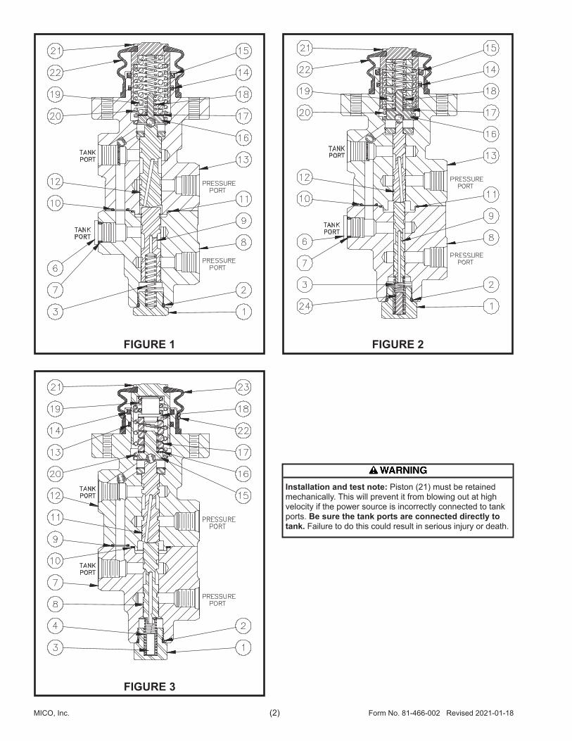
FIGURE 1 FIGURE 2
FIGURE 3
Installation and test note: Piston (21) must be retained mechanically. This will prevent it from blowing out at high velocity if the power source is incorrectly connected to tank ports. Be sure the tank ports are connected directly to tank. Failure to do this could result in serious injury or death.

Form No. 81-466-002 Revised 2021-01-18 (3) MICO, Inc.
DISASSEMBLY(Refer to Figures 1 and 4)
1. Remove boot (22) from piston (21) and housing (13). Not all models use boot (22). 2. Remove piston (21), springs (18, 19 & 20), shim(s) (17), and retainer assembly (16) from housing (13). Not all models use spring (18). NOTE: Be aware of the number of shim(s) being removed from housing. 3. Carefully remove cup (15) and seal (14) from housing (13) bore. NOTE: Be careful not to scratch or mar housing bore. 4. Remove end plug (1) and spring (3) from housing (8). Remove o-ring (2) from end plug (1). 5. Remove plug (6) from housing (8). Remove o-ring (7) from plug (6). Not all models use plug (6) and o-ring (7). 6. Separate housings (8 & 13) by removing cap screws (4) and washers (5). Remove o-rings (10 & 11) from housings (8 & 13). 7. Carefully remove spools (9 & 12) from housings (8 & 13). NOTE: Be careful not to damage spools or housing bores.
ASSEMBLY(Refer to Figures 1 and 4)LUBRICATE ALL RUBBER COMPONENTS FROM REPAIR KIT WITH CLEAN TYPE FLUID USED IN THE SYSTEM. 1. Clean all parts thoroughly before assembling. 2. Install new o-rings (10 & 11) in proper o-ring pockets on housings (8 & 13). 3. Lubricate spool (12) with clean system fluid and carefully slide into bottom end of housing (13) bore.
MODELS:03-466-20203-466-20603-466-21003-466-21606-466-19506-466-21006-466-21306-466-21606-466-21806-466-22806-466-23006-466-23106-466-23206-466-23406-466-23806-466-240
06-466-24106-466-24406-466-24506-466-24806-466-25306-466-25906-466-26306-466-26406-466-26606-466-26806-466-27006-466-28006-466-28606-466-29206-466-29506-466-29906-466-301
06-466-30306-466-31506-466-31606-466-40906-466-42506-466-43006-466-44706-466-53606-466-55906-466-80606-466-91906-466-93920-100-83320-100-930
NOTEHousings (8 & 13) and spools (9 & 12) are manufactured as matched sets. These sets (housing & spool) must not be intermixed with other parts.
Do not intermix spools and housings. Spool (9) and housing (8) are a matched set as are spool (12) and housing (13).
Note direction of spool (12). NOTE: Spool must slide freely into bore. If either part is damaged, a new valve assembly may be required. 4. Reassemble housings (8 & 13) using cap screws (4) and washers (5). Use Loctite 242 on cap screws and torque 29.8-33.9 N·m (22-25 lb·ft). NOTE: Make sure housings line up correctly and o-rings (10 & 11) remain in the pockets during assembly. 5. Install new o-ring (7) on plug (6) and install plug (6) in housing (8). Torque plug (6) 27.1-32.5 N·m (20-24 lb·ft). Not all models use plug (6) and o-ring (7). 6. Lubricate spool (9) with clean system fluid and carefully slide into housing (8) bore. Note direction of spool (9). NOTE: Spool must slide freely into bore. If either part is damaged, a new valve assembly may be required. 7. Install new o-ring (2) on end plug (1). 8. Install spring (3) and end plug (1) into housing (8). Torque end plug 47.5-54.2 N·m (35-40 lb·ft). 9. Carefully install new cup (15) and new seal (14) into housing (13) bore. Note direction and order of
cup and seal. NOTE: Be careful not to scratch or mar housing bore.10. Assemble springs (18, 19, & 20), shim(s) (17) and retainer assembly (16) in piston (21). Not all models use spring (18).11. Carefully install piston (21) assembly into housing (13) bore.12. Install new boot (22) on housing (13) and piston (21). Not all models use boot (22).13. When reinstalling pedal actuated valve use new hex cap screws (23), 5/16-18UNC SAE grade 8. Torque cap screws 24.4-29.8 N·m (18-22 lb·ft). NOTE: Not all repair kits include cap screws (23).
NOTEAfter service, the valve must develop the pressure indicated in the specifications, TABLE 1. Shim(s) (17) are used to obtain the correct pressure setting. Contact MICO if brake pressure setting is not able to be obtained.
● Items included in Repair Kit Not all models use these parts
FIGURE 4

MICO, Inc. (4) Form No. 81-466-002 Revised 2021-01-18
DISASSEMBLY(Refer to Figures 2 and 5)
1. Remove boot (22) from piston (21) and housing (13). Not all models use boot (22). 2. Remove piston (21), springs (18, 19 & 20), shim(s) (17), and retainer assembly (16) from housing (13). Not all models use spring (18). NOTE: Be aware of the number of shim(s) being removed from housing. 3. Carefully remove cup (15) and seal (14) from housing (13) bore. NOTE: Be careful not to scratch or mar housing bore. 4. Remove end plug (1) and spring (3) from housing (8). Remove o-ring (2) from end plug (1). 5. Remove plug (6) from housing (8). Remove o-ring (7) from plug (6). Not all models use plug (6) and o-ring (7). 6. Separate housings (8 & 13) by removing cap screws (4) and washers (5). Remove o-rings (10 & 11) from housings (8 & 13). 7. Carefully remove spools (9 & 12) from housings (8 & 13). NOTE: Be careful not to damage spools or housing bores.
ASSEMBLY(Refer to Figures 2 and 5)LUBRICATE ALL RUBBER COMPONENTS FROM REPAIR KIT WITH CLEAN TYPE FLUID USED IN THE SYSTEM. 1. Clean all parts thoroughly before assembling. 2. Install new o-rings (10 & 11) in proper o-ring pockets on housings (8 & 13). 3. Lubricate spool (12) with clean system fluid and carefully slide into bottom end of housing (13) bore.
MODELS:03-466-20103-466-20303-466-20403-466-20803-466-21206-466-20006-466-20106-466-20206-466-20406-466-20606-466-20706-466-20806-466-20906-466-21406-466-22006-466-22206-466-22706-466-229
06-466-23306-466-23506-466-23606-466-23706-466-23906-466-24606-466-25006-466-25206-466-25806-466-26006-466-26206-466-28206-466-28406-466-28506-466-28706-466-28806-466-29006-466-29606-466-297
06-466-29806-466-35406-466-38706-466-39506-466-42906-466-47306-466-48806-466-58306-466-60106-466-61406-466-91606-466-91420-100-74920-100-80120-100-80820-100-95240710106604071010670
NOTEHousings (8 & 13) and spools (9 & 12) are manufactured as matched sets. These sets (housing & spool) must not be intermixed with other parts.
Do not intermix spools & housings. Spool (9) and housing (8) are a matched set as are spool (12) and housing (13).
Note direction of spool (12). NOTE: Spool must slide freely into bore. If either part is damaged, a new valve assembly may be required. 4. Reassemble housings (8 & 13) using cap screws (4) and washers (5). Use Loctite 242 on cap screws and torque 29.8-33.9 N·m (22-25 lb·ft). NOTE: Make sure housings line up correctly and o-rings (10 & 11) remain in the pockets during assembly. 5. Install new o-ring (7) on plug (6) and install plug (6) in housing (8). Torque plug (6) 27.1-32.5 N·m (20-24 lb·ft). Not all models use plug (6) and o-ring (7). 6. Lubricate spool (9) with clean system fluid and carefully slide into housing (8) bore. Note direction of spool (9). NOTE: Spool must slide freely into bore. If either part is damaged, a new valve assembly may be required. 7. Install new o-ring (2) on end plug (1). 8. Install spring (3) and end plug (1) into housing (8). Torque end plug 47.5-54.2 N·m (35-40 lb·ft). 9. Carefully install new cup (15) and new seal (14) into housing (13)
bore. Note direction and order of cup and seal. NOTE: Be careful not to scratch or mar housing bore.10. Assemble springs (18, 19, & 20), shim(s) (17) and retainer assembly (16) in piston (21). Not all models use spring (18).11. Carefully install piston (21) assembly into housing (13) bore.12. Install new boot (22) on housing (13) and piston (21). Not all models use boot (22).13. When reinstalling pedal actuated valve use new hex cap screws (23), 5/16-18UNC SAE grade 8. Torque cap screws 24.4-29.8 N·m (18-22 lb·ft). NOTE: Not all repair kits include cap screws (23).
● Items included in Repair Kit Not all models use these parts
FIGURE 5
NOTEAfter service, the valve must develop the pressure indicated in the specifications, TABLE 1. Shim(s) (17) are used to obtain the correct pressure setting. Contact MICO if brake pressure setting is not able to be obtained.

Form No. 81-466-002 Revised 2021-01-18 (5) MICO, Inc.
DISASSEMBLY(Refer to Figures 3 and 6)
1. Remove boot (23) from piston (21) and housing (12). Not all models use boot (22). 2. Remove piston (21), springs (19 & 20), retainer (18), spring (17), shim(s) (16) and retainer assembly (15) from housing (12). NOTE: Be aware of the number of shim(s) being removed from housing. 3. Carefully remove cup (14) and seal (13) from housing (12) bore. NOTE: Be careful not to scratch or mar housing bore. 4. Remove end plug (1), retainer (3), and spring (4) from housing (7). Remove o-ring (2) from end plug (1). 5. Separate housings (7 & 12) by removing cap screws (5) and washers (6). Remove o-rings (9 & 10) from housings (7 & 12). 6. arefully remove spools (8 & 11) from housings (7 & 12). NOTE: Be careful not to damage spools or housing bores.
ASSEMBLY(Refer to Figures 2 and 5)LUBRICATE ALL RUBBER COMPONENTS FROM REPAIR KIT WITH CLEAN TYPE FLUID USED IN THE SYSTEM. 1. Clean all parts thoroughly before assembling. 2. Install new o-rings (9 & 10) in proper o-ring pockets on housings (7 & 12). 3. Lubricate spool (11) with clean system fluid and carefully slide into bottom end of housing (12) bore. Note direction of spool (11). NOTE: Spool must slide freely into bore. If either part is damaged, a new valve assembly may be required. 4. Reassemble housings (7 & 12) using cap screws (5) and washers (6). Use Loctite 242 on cap screws and torque 29.8-33.9 N·m (22-25 lb·ft). NOTE: Make sure housings line up correctly and o-rings (9 & 10) remain in the pockets during assembly.
MODEL:20-100-749
NOTEHousings (7 & 12) and spools (8 & 11) are manufactured as matched sets. These sets (housing & spool) must not be intermixed with other parts.
Do not intermix spools & housings. Spool (9) and housing (8) are a matched set as are spool (12) and housing (13).
5. Lubricate spool (8) with clean system fluid and carefully slide into housing (7) bore. Note direction of spool (8). NOTE: Spool must slide freely into bore. If either part is damaged, a new valve assembly may be required. 6. Install new o-ring (2) on end plug (1). 7. Install spring (4), retainer (3), and end plug (1) into housing (7). Torque end plug 47.5-54.2 N·m (35-40 lb·ft). 8. Carefully install new cup (14) and new seal (13) into housing (12) bore. Note direction and order of cup and seal. NOTE: Be careful not to scratch or mar housing bore. 9. Assemble springs (19 & 20), retainer (18), spring (17), shim(s) (16) and retainer assembly (15) in piston (21).
10 Carefully install piston (21) assembly into housing (12) bore. 11 Install new boot (23) on housing (12) and piston (21). Install retaining ring (22) on boot (23).
● Items included in Repair Kit
FIGURE 6
NOTEAfter service, the valve must develop the pressure indicated in the specifications, TABLE 1. Shim(s) (17) are used to obtain the correct pressure setting. Contact MICO if brake pressure setting is not able to be obtained.

MICO, Inc. (6) Form No. 81-466-002 Revised 2021-01-18
Brake lines should be bled very carefully as soon as the valve is installed in the machine. Air in the system will not allow the brakes to release properly and may severely damage them. 1. Start engine and allow accumulator to reach full charge. Shut down engine, then slowly apply and release brakes, waiting one minute between applications until brakes will not apply. Repeat this step three times. 2. Operate engine to maintain accumulator pressure within working limits throughout the bleeding procedure. 3. Open bleeder screw at wheel closest to brake valve and apply brakes cautiously until all air is bled out of line. Then close bleeder screw. Repeat this step at each
wheel, moving to the next farthest wheel from the brake valve each time, as follows: a. Left front b. Right front c. Right rear d. Left rear 4. Release brake pressure for at least one (1) minute. 5. Apply brakes, holding pedal down 10 seconds; then re lease pressure for one (1) minute. Repeat this step two more times. 6. Repeat step 3. 7. Check for system leaks and be sure of proper brake operation.
BLEEDING
BRAKES SLOW TO APPLY 1. No or improper gas charge in accumulator 1. Check gas charge 2. Brakes not properly adjusted 2. Adjust brakes 3. Inoperative brakes 3. Check brakes 4. Hydraulic lines or fittings leaking 4. Check for leaks and repair 5. Inoperative automatic adjuster 5. Check adjuster operation 6. Damaged hydraulic brake lines 6. Check lines for dents that re- strict flow of oil
INSUFFICIENT BRAKES 1. No oil or low oil level in tank 1. Check oil level in tank 2. Brakes not properly adjusted 2. Check brake adjustment 3. Oil or grease on brake lining 3. Clean or install new linings 4. Brake line damaged 4. Check lines and replace 5. Inoperative automatic adjusters 5. Check operation of adjusters 6. No or improper gas charge in accumulator 6. Check gas charge 7. Inoperative brakes 7. Check brakes
8. Brake valve inoperative 8. Replace valve 9. Inoperative system relief valve 9. Check pressure in pressure line to valve 10. Worn pump 10. Check pressure in pressure line to valve
EXCESSIVE BRAKING 1. Inoperative brakes 1. Check brakes 2. Inoperative brake valve 2. Replace brake valve
BRAKES WILL NOT RELEASE COMPLETELY 1. Brakes not properly adjusted 1. Adjust brakes 2. Inoperative brakes 2. Check brakes 3. Pedal angle out of adjustment 3. Adjust pedal angle 4. Inoperative wheel cylinders 4. Replace wheel cylinders 5. Inoperative automatic adjuster 5. Check operation of adjusters 6. Air in brakes (when automatic adjusters used Goodrich Hi-torque Brakes only) 6. Bleed brakes
7. Pressure on return line too high 7. Reduce pressure 8. Inoperative brake valve 8. Replace brake valve
NO BRAKES 1. No oil in hydraulic system 1. Check oil level in tank 2. Broken or damaged brake line 2. Check lines for breaks or damaged condition 3. Brakes not properly adjusted 3. Adjust brakes 4. Inoperative system relief valve 4. Check pressure in pressure line to valve 5. Worn pump 5. Check pressure in pressure line to valve 6. Inoperative automatic adjuster 6. Check brake line pressure 7. Inoperative or worn brakes 7. Check brakes 8. Inoperative brake valve 8. Replace brake valve
PEDAL KICKBACK WHEN BRAKES ARE APPLIED 1. Air in brakes 1. Bleed brakes
SERVICE CHECKS FOR 466 SERIES POWER BRAKE VALVES
SERVICE DIAGNOSIS(Refer to Figures 1, 2, 4, and 5)
BRAKES WILL NOT RELEASE COMPLETELY 1. Piston (21) binding 2. Pedal angle out of adjustment 3. Spring (3) broken
BRAKES WILL NOT RELEASE 1. Binding spools (9 & 12) 2. Piston (21) binding
NO BRAKES 1. Piston (21) binding 2. Broken spring (19)
OUTLET PRESSURE TOO HIGH (EXCESSIVE BRAKING) 1. Too many shims (17) installed in valve.
EXCESSIVE ACCUMULATOR LEAKAGE WHEN BRAKES ARE APPLIED 1. Damaged spools (9 & 12) 2. Damaged housings (8 & 13)
EXCESSIVE ACCUMULATOR LEAKAGE WHEN BRAKES ARE NOT BEING USED 1. Damaged spools (9 & 12) 2. Damaged housings (8 & 13)
INSUFFICIENT BRAKES 1. Broken spring (19) 2. Pedal travel is inhibited
SERVICE DIAGNOSIS(Refer to Figures 3 and 6)
BRAKES WILL NOT RELEASE COMPLETELY 1. Piston (21) binding 2. Pedal angle out of adjustment 3. Spring (4) broken
BRAKES WILL NOT RELEASE 1. Binding spools (8 & 11) 2. Piston (21) binding
NO BRAKES 1. Piston (21) binding 2. Broken spring (17)
OUTLET PRESSURE TOO HIGH(EXCESSIVE BRAKING) 1. Too many shims (16) installed in valve.
EXCESSIVE ACCUMULATOR LEAKAGE WHEN BRAKES ARE APPLIED 1. Damaged spools (8 & 11) 2. Damaged housings (7 & 12)
EXCESSIVE ACCUMULATOR LEAKAGE WHEN BRAKES ARE NOT BEING USED 1. Damaged spools (8 & 11) 2. Damaged housings (7 & 12)
INSUFFICIENT BRAKES 1. Broken spring (17) 2. Pedal travel is inhibited

Form No. 81-466-002 Revised 2021-01-18 (7) MICO, Inc.

This document is intended to provide general information about MICO Products. MICO, Inc. has attempted to present accurate information about MICO Products in its catalogs, brochures, and other printed materials. MICO, Inc. is not responsible for errors, inaccuracies, or inconsistencies that may exist in any catalog, brochure, or other printed materials or any damages arising from or related to reliance on information in them. Materials and specifications for MICO Products set forth in catalogs, brochures, and other printed materials are subject to change without notice or obligation. Refer to www.mico.com for the most recent versions of our literature. If you have any questions concerning MICO Products, please contact MICO, Inc. All MICO Products and service are sold and provided subject to the MICO Warranty at www.mico.com in effect on the date of sale or supply.
MICO is a trademark and registered trademark of MICO, Inc. MICO is registered in the U.S. Patent and Trademark Office as well as in Australia, Canada, Indonesia, Japan, Peoples Republic of China, South Korea, and the European Community.
MICO, Inc. 1911 Lee Boulevard / North Mankato, MN U.S.A. 56003-2507 Tel: +1 507 625 6426 Fax: +1 507 625 3212
Form No. 81-466-002 Revised 2021-01-18 www.mico.com