SERVICE INSTRUCTIONS - Suaudeau.eu INSTRUCTIONS for Mamiya M645 M6451000S G~neral Speci fi cat ions...
81
• ami SERVICE INSTRUCTIONS for Mamiya M645 M6451000S Speci fi ca t ions ..... . ..• . ... . ....... . .. 1 Page T ro ub 1 e S hoo t i n g • . . . . • . . . • • . • . • . • . • •. •• •.• •• •• 5 Re p a i r Ma nua l . . . . . . . . . . . . . . . . . . . . . . . . . . . . • . . , 1 3 Spec ial Too l Li st and Spec ia l M eas u ri ng Inst rumen t .. . .... . ........ 81 Pages 2, 6, 14, 80 and 82 are blank M *· TOKYO , JAPAN S .l. 78-10 - M64 5
Transcript of SERVICE INSTRUCTIONS - Suaudeau.eu INSTRUCTIONS for Mamiya M645 M6451000S G~neral Speci fi cat ions...

• ami
SERVICE INSTRUCTIONS
for
Mamiya M645 M6451000S
G~neral Speci fi ca t ions ..... . ..• . ... . ....... . .. 1 Page
T ro ub 1 e S hoo t i n g • . . . . • . . . • • . • . • . • . • •. •• • . • •• • • 5
Re p a i r Ma n ua l . . . . . . . . . . . . . . . . . . . . . . . . . . . . • . . , 1 3 Spec i a l Too l Li st and
Spec ia l Meas uri ng Ins t rumen t .. . .... . ........ 81
Pages 2, 6, 14, 80 and 82 are blank
M *· CAM9!!!~xg TOKYO , JAPAN S.l. 78-10 - M64 5
General Specifications for
Mamiya M645
- 1-
General Spec i ficat i on for Mami ya M645
Camera body
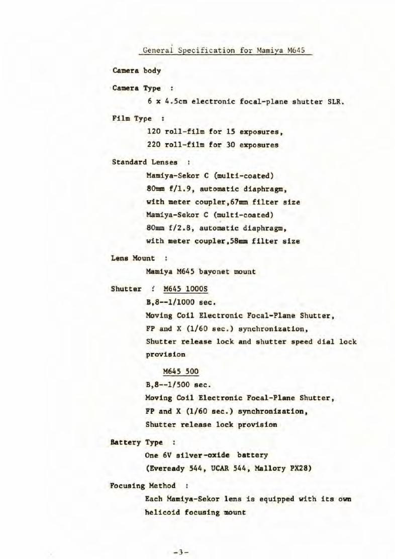
Camera Type
6 x 4.5cm electronic focal -pl ane shutter SLR.
Film Type
120 roll-film for 15 exposures,
220 r oll- film for 30 exposures
Standard Lenses
Mamiya-Sekor C (multi-coated)
80mm f/1.9, automatic diaphragm,
with meter coupler, 67mm filter size
Mamiya-Sekor C (multi- coated)
80mm f/2.8, automatic diaphragm,
with meter coupler,5811111 filter size
Lens Mount
Mamiya M645 bayonet mount
Shutter : M645 lOOOS
B,8--1/1000 sec.
Moving Coil Electronic Focal- Plane Shutter,
FP and X (l/60 sec.) synchronization,
Shutter release lock and shutter speed dial lock
provision
M645 500
B,8-- 1/500 sec.
Moving Coil Electronic Focal-Plane Shutter,
FP and X (l/60 sec.) synchronization,
Shutter release lock provision
Battery Type
One 6V silver-oxide battery
(Eveready 544, UCAR 544, Mallory PX28)
Focusing Method
Each Mamiya-Sekor lens is equipped with its own
helicoid focusing mount
- 3-
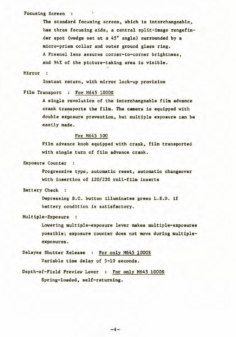
Focusing 5creen
Mirror
The standard focusing screen, which is interchangeable,
has three focusing aids, a central split-image r engefin
der spot (wedge set at a 45° angle) surrounded by a
micro-prism collar and outer ground glass ring.
A Fresnel lens assures corner-to-corner brightness ,
and 94% of the picture-taking area is visible.
Instant return, with mirror lock-up provision
Film Transport For M645 10005
A single revolution of the interchangeable film advance
crank tra~sports the film. The camera is equipped with
double exRosure prevention, but multiple exposure can be
easily made.
For M645 500
Film advance knob equipped with cra~k , film transported
with single turn of film advance crank,
Exposure Counter
Progressive type, automatic reset, automatic changeover
with insertion of 120/220 roll-film i nserts
Battery Check
Depressing B.C. button illuminates green L.E.D. if
battery condit i on is satisfactory.
Multiple-Exposure :
Lowering multiple-exposure lever makes multiple-exposures
possible; exposure counter does not move during multiple
exposures.
Delayes Shutter Release For only M645 lOOOS
Variable time delay of 5-10 seconds.
Depth-of-Field Preview Lever Fo·r only M645 10005
5pring-loaded, self-returning.
-4-

Trouble Shooting for
Mamiya M645
-5-
c A
'• l
2
3
1 4
2 5
3 6
7
3
8
{ J..,I
2
l
' \
B
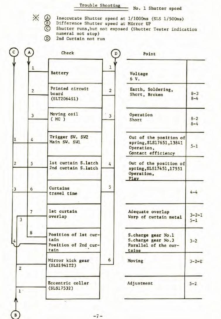
Trouble Shooting No. 1 Shutter speed
Inaccurate Shutter speed at l/lOOOms (SLS l/SOOms) Difference Shutter speed at Mirror UP
® Shu tter runs ,but not exposed (Shutter Tester indication numeral no t stop) 2nd Curtain not run
Check D Point
' 1
Rattery Voltage 6 V.
Printed circuit 2 board (SLT2064Sl)
Earth, Soldering, 8-3 Short, Broken 8-4
Moving coil 3 ( MC )
Operation 8-2 Short 8-4
Trigger SW. SW2 Main sw. sm.
Out of the position of spri ng,SLS17651,13841
5-1 Operation, Contact efficiency
lst curtain S.latch 4 2nd curtain S.latch
Out of the posi tion of spri ng , SLS17451 ,1 7551 Operat i on , Pl Av
Curtains 5 travel time 4-4
lst curtain overlap
Adequate over lap 3- 2-I Warp of curtain metal 5-1
Position of lst cur- S.charge gear No .1 tain S.charge gear No.3 3-2 Position of 2nd cur-- Parallel of the cur-tain
.. tains
Mirror kick gear 6 Moving 3-2,...E (SLS1941T2)
Eccentric col lar Adjustment 5-2 (SLS17532)
-7-
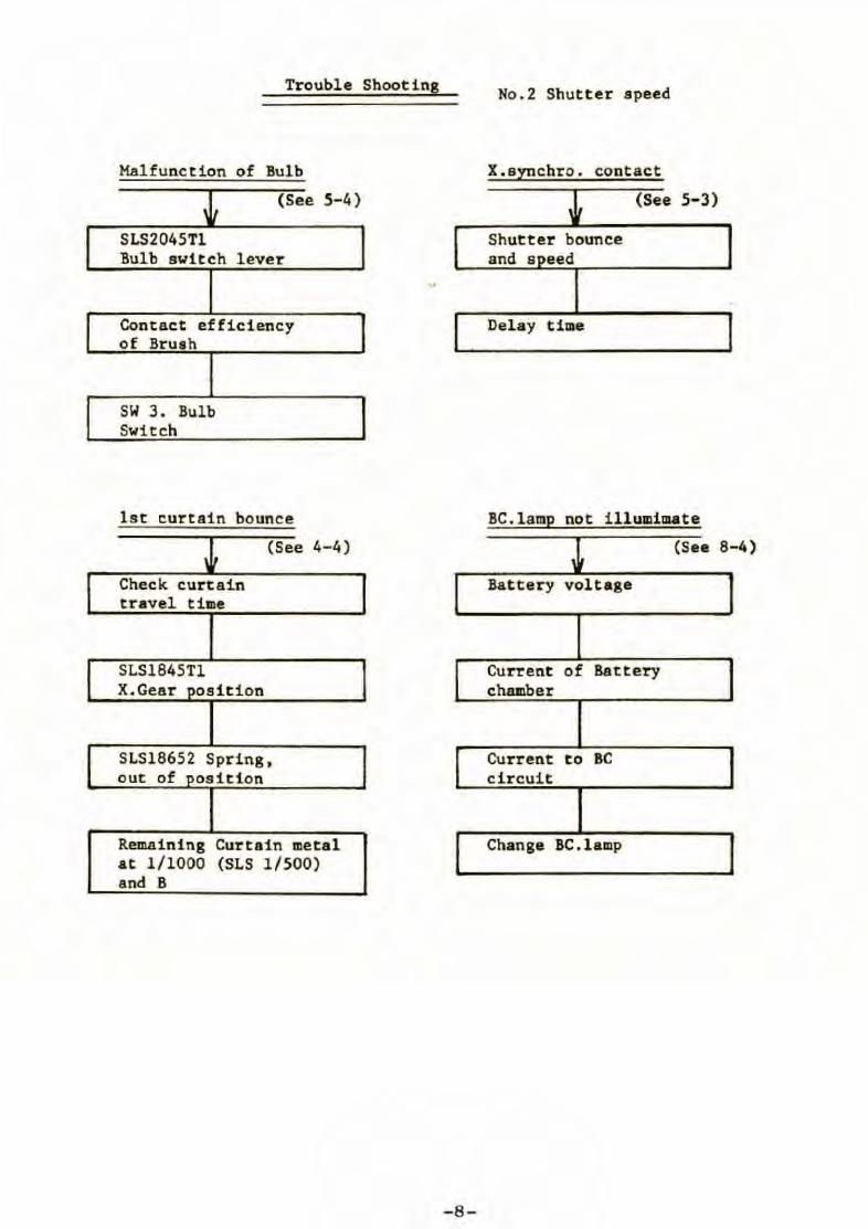
Trouble Shooting
Malfunction of Bulb
~ (See 5-4)
SLS2045Tl Bulb switch lever
Contact ef f ici ency of Bruah
SW 3. Bulb Switch
l st curtain bounce
~ (See 4-4)
Check cur tain travel time
SLS1845Tl X.Gear pos ition
SLS18652 Spring , out of posit i on
Remaining Curta in met al at 1/1000 (SLS 1/500) and B
- 8-
No.2 Shutter speed
X.synchro. contact
(See 5- 3)
Shutter bounce and s eed
Del ay time
BC. lamp not i llumi mate
(See 8
Bat tery voltage
Current of Battery chamber
Cur rent to BC circuit
Change BC. l amp
-4 )
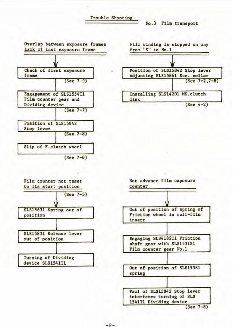
Trouble Shooting
Overlap betveen exposure frames Lack of l ast exposure frame
1 I
Check of first exposure frame
(See 7-9)
Engagement of SLS1554Tl Film counter ge.ar and Dividing device
{See 7- 7)
Pos ition of SLS15842 Stop lever
(See 7-8)
Sl ip of F. clutch wheel
(See 7-6)
Film counter not rese t to its start position
(See 7-5)
1 ,
SLS15631 Spr ing out of position
SLS1583l Release lever out of position
Turning of Dividing device SLS1541Tl
-9-
No.3 Film transport
Film windi ng is stopped on way from "S" to No . 1
, , Position of SLS15842 Stop lever Adjustins SLS15861 Ecc . collar
(See 7- 2,7- 8)
Installing SLS14201 MS.clut ch disk
(See 4-2)
Not advance film exposure counter
, , Out of position of spring of Friction wheel in roll - film insert
Engaging SLS4182Tl Friction shaft gear with SLS1531Sl Film counter gear No.l
Out of pos ition of SLS15381 spring
Pawl of SLS15842 Stop lever i nterferes t urning of SLS 1541Tl Dividing device
(See 7- 8)
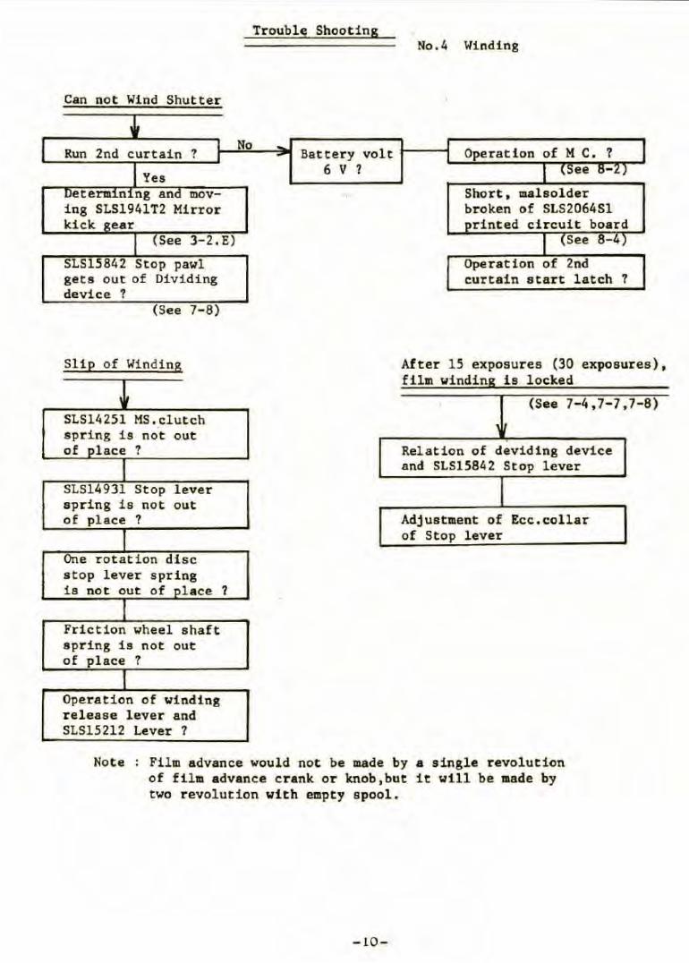
Can not Wind Shutter
Run 2nd curtain ?
See 3-2 . E)
SLS15842 Stop pawl geta out of Dividing device ?
(See 7-8)
Slip of Winding
~ SLS14251 MS . clutch apri ng is not out of pl ace ?
1 SLS14931 Stop lever s pring is not out of place 1
1 One rotation dise stop lever spring is not out of olace
1 Fri ction wheel shaft spr ing ia not out of place ?
1 Operation of vinding r elease l ever and SLS15212 Lever ?
?
No
Troubls Shooting
Batter y volt · 6 V ?
No.4 Winding
0 eration of M C. ?
Short, malsolder broken of SLS2064Sl rinted circuit board
See 8-4
Oper ation of 2nd curtain star t latch ?
After 15 exposures (30 exposures) , film winding i s locked
(See 7-4 , 7- 7,7-8) 1
Rel ation of devid i ng device and SLS15842 Stop lever
Adjustment of Ecc.col lar of Stop lever
Note Film advance would not be made by a single revolution of film advance c r ank or knob , but it v t l l be made by two revolut ion with empty s pool.
-10 -
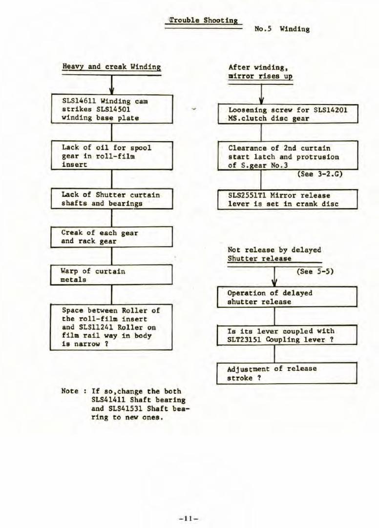
'\l'rouble Shooting
Heavy and creak Winding
' SLS146ll Winding cam strikes SLS14501 winding base plate
Lack of oil for spool gear in roll-film inserc
Laek of Shutter curtain shafts and bearinge
Creak of each gear and rack gear
Warp of curtain metals
Space between Roller of the roll-film insert and SLS11241 Roller on fil m rail way in body is narrow ?
Note If so,change the both SLS41411 Shaft bearing and SLS41531 Shaft bearing to new ones.
- 11-
No.5 Winding
After w1nd1ng, mirror rises up
Loosening screw for MS.eluteh dise gear
SLS14201
Clearance of 2nd curtain start latch and protrusion of S.izear No.3
(See 3-2.G)
SLS2551Tl Mirror rel eaee lever i s set in crank dise
Not release by delayed Shutter release
(See 5-5) ' ,
Operation of delayed shutter release
Is its lever coupled with SLT23151 Coupling lever ?
Adjustment of release stroke ?
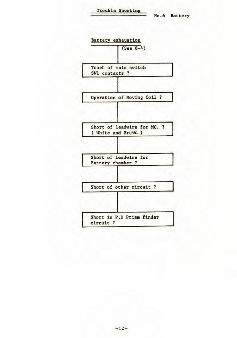
Trouble Shootins No .6 Battery
Battery exhaustion
(See 8-4 )
Touch of main switch SWl contacts ?
Operation of Hoving Coil ?
Short of leadwire for HC. ? ( White and Brown )
Short of leadwire for Battery chamber 1
Short of ot her circuit ?
Shor t in P. D Prism f indel' circuit ?
-lZ-

Repair., Manual for
Mamiya M645 Camera Body
-13 -
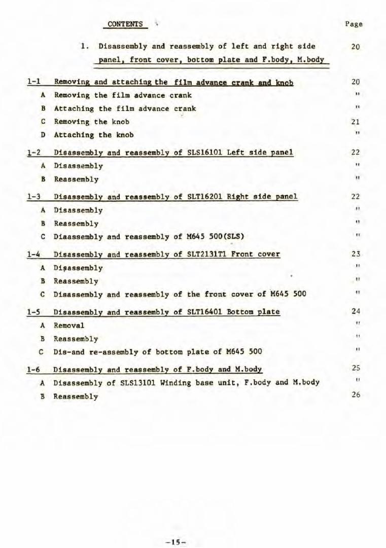
CONTENTS . . Page
1. Di sassembly and reassembly of left and right side 20
panel, front cover, bottom plate and F.body, M.body
1-1 Removing and attaching the film advance crank and knob
A Removing the film advance crank
B Attaching the film advance crank
C Removing the knob
D Attaching the knob
,
1- 2 Di sassembly and reassembly of SLS16101 Left side panel
A Disassembly
B Reassembl y
1-3 Disassembly a~d reassembly of SLT16201 Right aide panel
A Disassembly
B Reassembly
C Diaassembly and reassembly of M645 500(SLS)
1-4 Di sassembly and reassembly of SLT2131Tl Front cover
A Di~assembly
B Reassembly
C Disassembly and reassembly of the front cover of M645 500
1-5 Disassembly and reassembly of SLT16401 Bottom plate
A Removal
B Reassembl y
C Dis-and re-assembly of bottom plate of M645 500
1-6 Disassembly and reassembly of F. body and M.body
A Disassembly of SLS13101 Wi nding base unit, F .body and M.body
B Reass embly
- 15-
20
" "
21
"
22
"
" 22
" " "
23
" " "
24
"
" "
2S
" 26
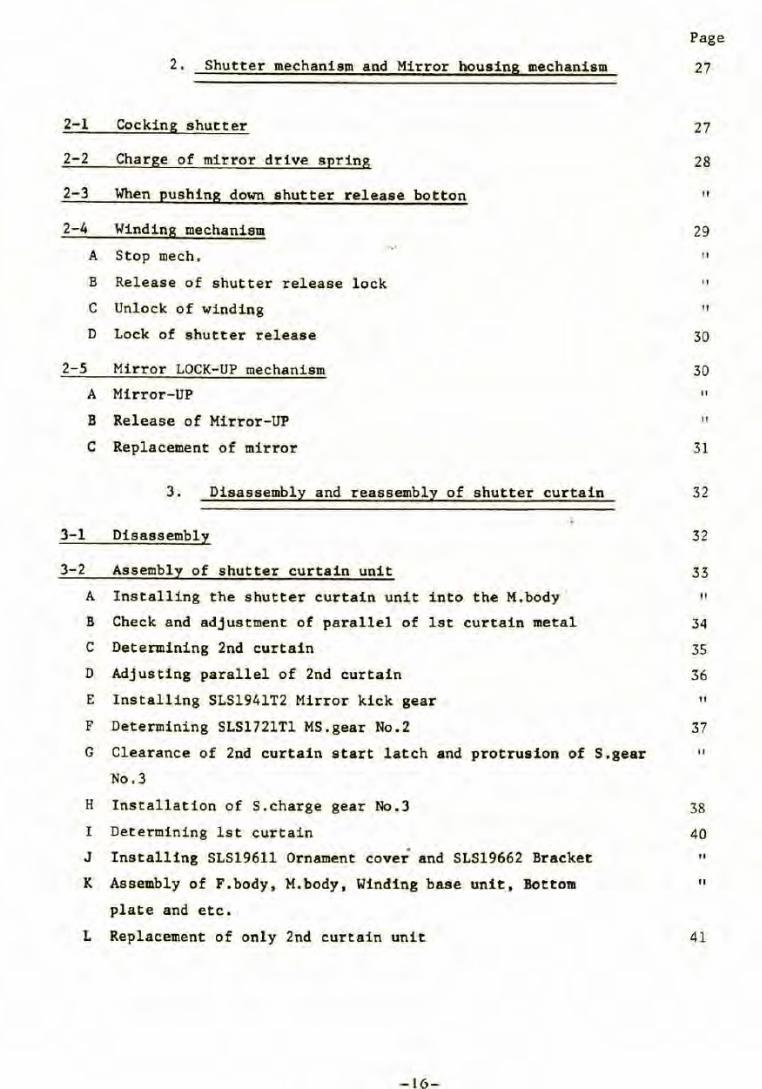
2. Shutter mechanism and Mirror bousins mechanism
2-1 Cocking shutter
2- 2 Charge of mirror drive spring
2-3 When pushing down shutter release botton
2-4 Winding mechanism
A Stop mech. , .
B Release of shutter release lock
c Unlock of winding
D Lock of shutter release
2-5 Mirror LOCK-UP mechanism
A Mirror-UP
B Release of Mirror-UP
c Replacement of mirror
3. Disassembly and reassembly of shutter curtain
3-1 Disassembly
3-2 Assembly of shutter curtain unit
A Installing the shutter curtain unit into the M.body ·
B Check and adjustment of parallel of lst curtain metal
C Determining 2nd curtain
D Adjusting parallel of 2nd curtain
E Ins t alling SLS1941T2 Mirror kick gear
F Determining SLS1721Tl MS.gear No.2
G Clearance of 2nd curtain start latch and protrusion of S.gear
No.3
H Installation of S.charge gear No.3
I Determining ls t curtain
J Installing SLS19611 Ornament cover and SLS19662 Bracket
K Assembly of F.body, M. body, Winding base unit, l!ottom
plate and etc.
L Replacement of only 2nd curtain unit
- 16-
Page
27
27
28
Il
29 Il
Il
" 30
30 Il
" 31
32
32
33
" 34
35
36
" 37 Il
38
40
" "
41
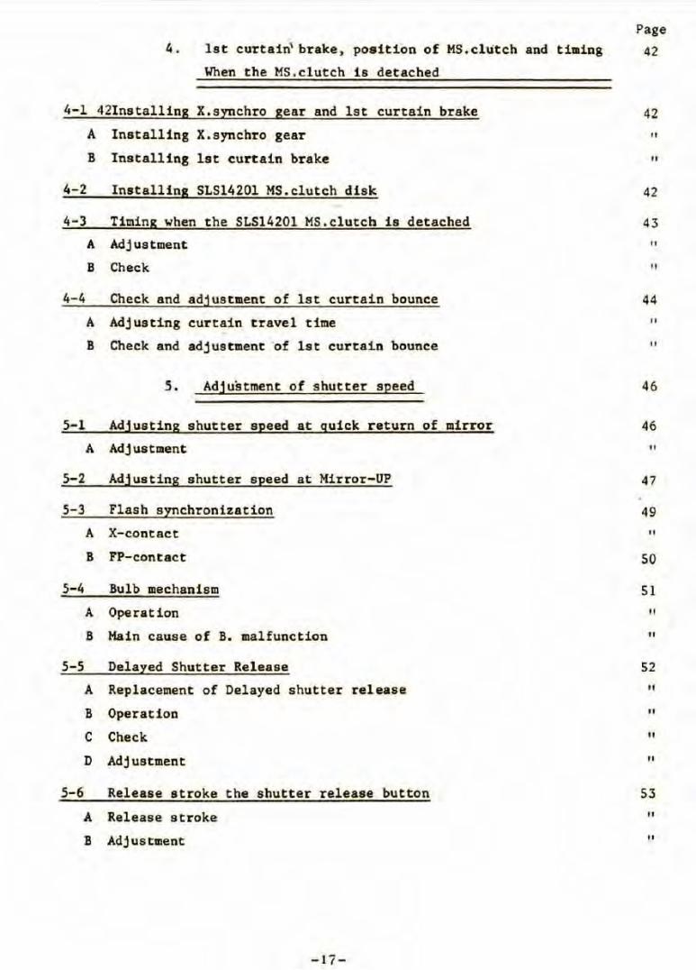
4. lst curtain\ brake, position of MS.cllitch and ti1Ding
When the MS.clutch is detached
4-1 42Installing X.sI!!chro gear and lst curtain brake
A Installing X.synchro gear
B Installing lst curtain brake
4-2 Installing SLS14201 MS.clutch disk
4-3 Timing when the SLS14201 MS.clutch is detached
A Adjustment
B Check
4-4 Check and adjustment of lst curtain bounce
A Adjusting curtain travel time
B Check and adjustment ·of lst curtain bounce
5. Adjustment of shutter speed
5-1 Adjusting shutter speed at quick return of mirror
A Adjustment
5-2 Adjusting shutter speed at Mirror-UP
5-3 Flash synchronization
A X-contact
B FP-contact
5-4 Bulb mechanism
A Operation
B Hain cause of B. malfunction
5-5 Delayed Shutter Release
A Replacement of Delayed shutter release
B Operation
C Check
D Adj ustment
5-6 Release stroke the shutter release button
A Release stroke
B Adjustment
-lï-
Page
42
42 Il
Il
42
43
Il
" 44
Il
Il
46
46 11
47
49 11
50
51 Il
11
52
" Il
" "
53 Il
Il
6. Body flange back ' and Finder infinity
6-1 Body flange back and flat of bayonet face
A Check
B Adjustment
6-2 Mirror angle 45° degress
A Check
B Adjustment
6-3 Adjusting infinity(oo) of Finder focus
A Check
B Adjusting infinity
7. Film transport mechani8111
7-1 Film transport
7-2 From start mark to the first exposure
7-3 Exposure counter No.2 ••.•
7-4 After 15 exposures for 120,30 exposures for 220
7-5 Reset to starting position "S"
7-6 Multiple-Exposure mechanism
7-7 De termine SLS1554Tl Film counter gear
A De termine SLS156ll Stopper
B De termine SLS1541Tl Dividing device
7- 8 Position of SLS15842 Stop lever
A New SLS15842 Stop lever
B Old type stop lever
7-9 Check and Adjustment of the first exposure frame position
on film
A Check the first exposure frame position
B Adjustment
-18-
Page
54
54 Il
55
56 Il
Il
57 Il
Il
58
59
60
Il
61
62
63
64 Il
Il
65 Il
Il
67
" Il
8-1
8- 2
8-3
8-4
8. Moving Coil mode, Electronic circuit and parts
Electronic circuit
A Tho exposure time control capacitor Cl discharges
B lleginning of charge te Cl capac i tor
c Determining exposure time
D Charge to capacitor C2
Replacement of the llOVing coil"
A Check by Tester
B Replacement of the 11ovi ng coll
Replacement SLT2064Sl Printed circuit
A Adjusting the variable resistor as shown in Pig . 92
Check electroni~ circuit by Tester
A Circuit
B Parts
C Hain cause for battery exhaus tion
- 19 -
Page
68
68
" " Il
Il
72 Il
75 Il
76 Il
77
79
1. Disassembly and reassembly of left and right side
panel, front cover, bottom plate and F.body, H.body
1-1 Removing and attaching the f ilm advance cr ank and knob
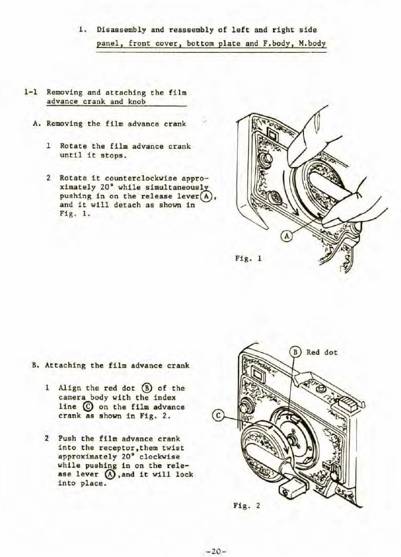
A. Removing the film advance crank
1 Rotate the film advance crank until it stops .
2 Rotate it counterclockwise approximately 20° while simultaneous~ pushing in on the release lever~, and it will de tach as shoWll in / Fig. 1.
B. Attaching the film advance crank
1 Align the red dot @ of the camera body with the index line © on the film advance crank as shown in Fig. 2.
2 Push the film advance crank in to the receptor,them twist approxi mately 20° clockwise while pushing in on the release lever @,and i t will lock into place.
Fig. 1
Fig . 2
-20-
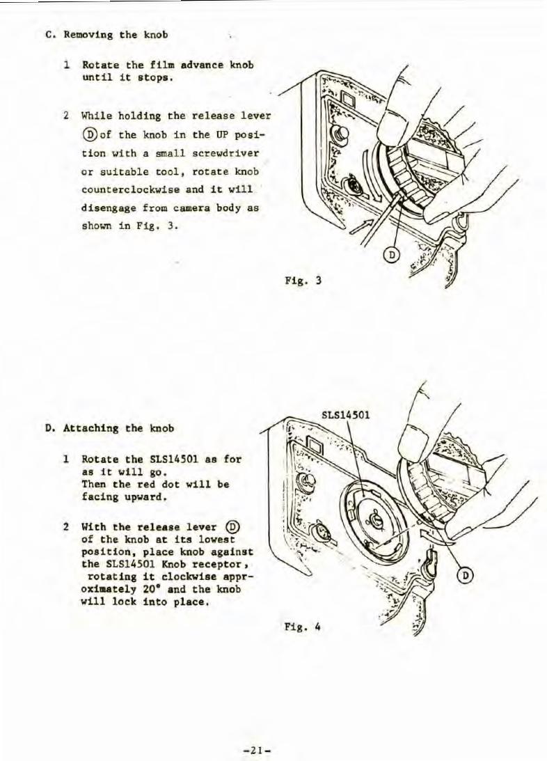
c. Removing the knob
1 Rotate t he film advance knob until it stops.
2 Whil e holding the release lever
@of the knob in the UP posi
tion \lith a small screwdriver
or suitable tool , rot ate knob
counterclockwise and it vill
disengage from camera body as
shovn in Fig. 3 .
D. Attaching the knob
l Rotate the SLS14501 as for as 1t wil l go. Then the red dot will be facing upvard.
2 With the release lever @ of t he knob at its lowest position, place knob against the SLS14501 Knob receptor, rotating it clockwiae appr
oxiaately 20• and the lcnob will lock into place.
- 21 -
Fig. 3
Fig. 4
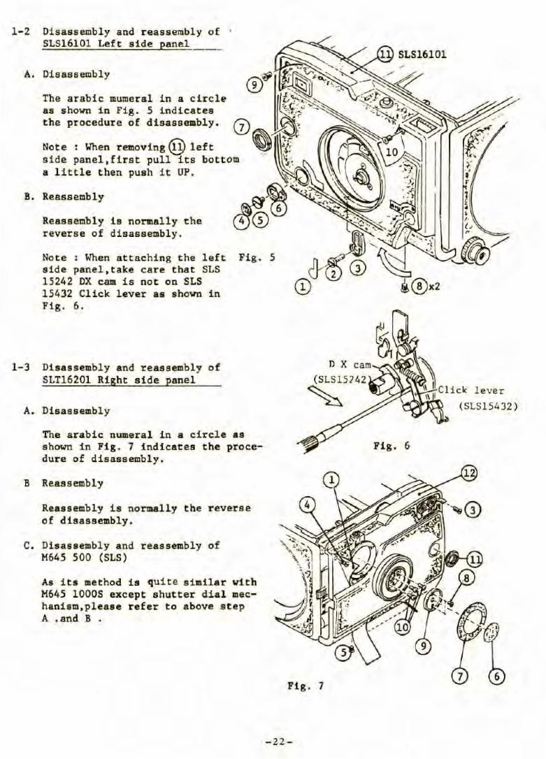
1-2 Disassembly and reassembly of • SLS16101 Left side pan1ü
A. Disassembly
The arabic mumeral in a c ircle as shown in Fi g. 5 indicates the procedure of disassembly.
B. Reassembly
Reassembly is normally the reverse of disassembly.
Note : 'When attaching the left side panel,take care that SLS 15242 DX cam is not on SLS 15432 Click lever as shown in Fig. 6.
Fig. 5
1-3 Disassembly and reassembly of SLT16201 Right side panel
A. Disassembly
The arabic numeral in a circle as shown in Fig. 7 indicates the procedure of disassembly.
B Reassembly
Reassembly is normally the reverse of disassembly.
C. Disassembly and reassembly of M645 500 (SLS)
As its method is quite similar vith M645 10005 except shutter dial mechanism, please refer to above step A .and B •
n X (SLS15242
~
Fig. 7
- 22 -
Fig. 6
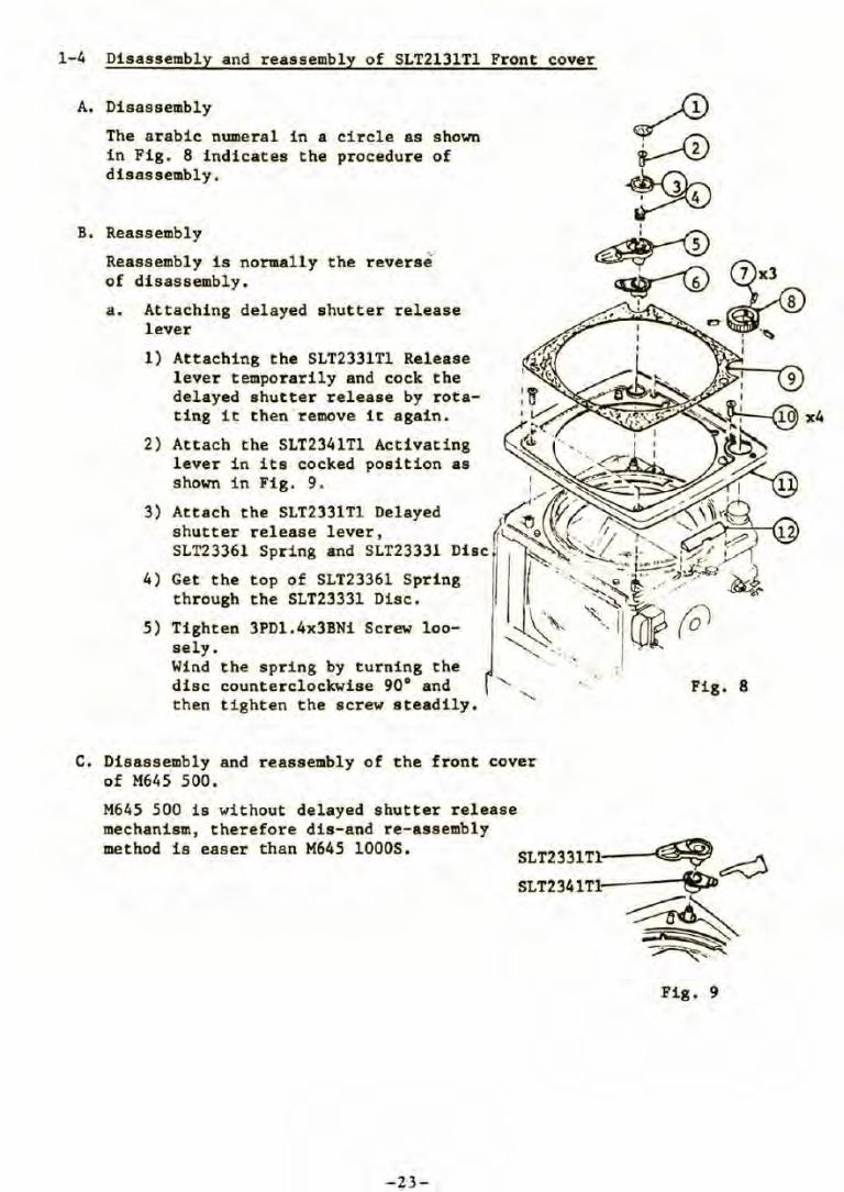
1-4 Disassembly and reassembly of SLT2131Tl Front cover
A. Disassembly
The arabic numeral in a circle as shown in Fig. 8 indicates the procedure of disassembly.
B. Reassembly
Reassembly is norm.ally the of disassembly.
,. reverse
a. Attaching delayed shutter release lever
1) Attaching the SLT2331Tl Release lever temporarily and cock the delayed shutter release by rotating it then remove it again.
2) Attach the SLT2341Tl Activating lever in its cocked position as shown in Fig. 9.
3) Attach the SLT2331Tl Delayed shutter release lever, SLT23361 Spring and SLT23331
4) Get the through
5) Tighten 3PDl.4x3BNi Screw loosely. Wind the spring by turning the dise counterclockwise 90° and then tighten the screw steadily.
C. Disassembly and reassembly of the front cover of M645 500.
Fig. 8
M645 500 is without delayed shutter release mechanism, therefore dis-and re-assembly method is easer than M645 lOOOS. SLT2331Tl---~--,«'h..~
SLT2341Tl: ~
~ ~~
Fig . 9
-23-
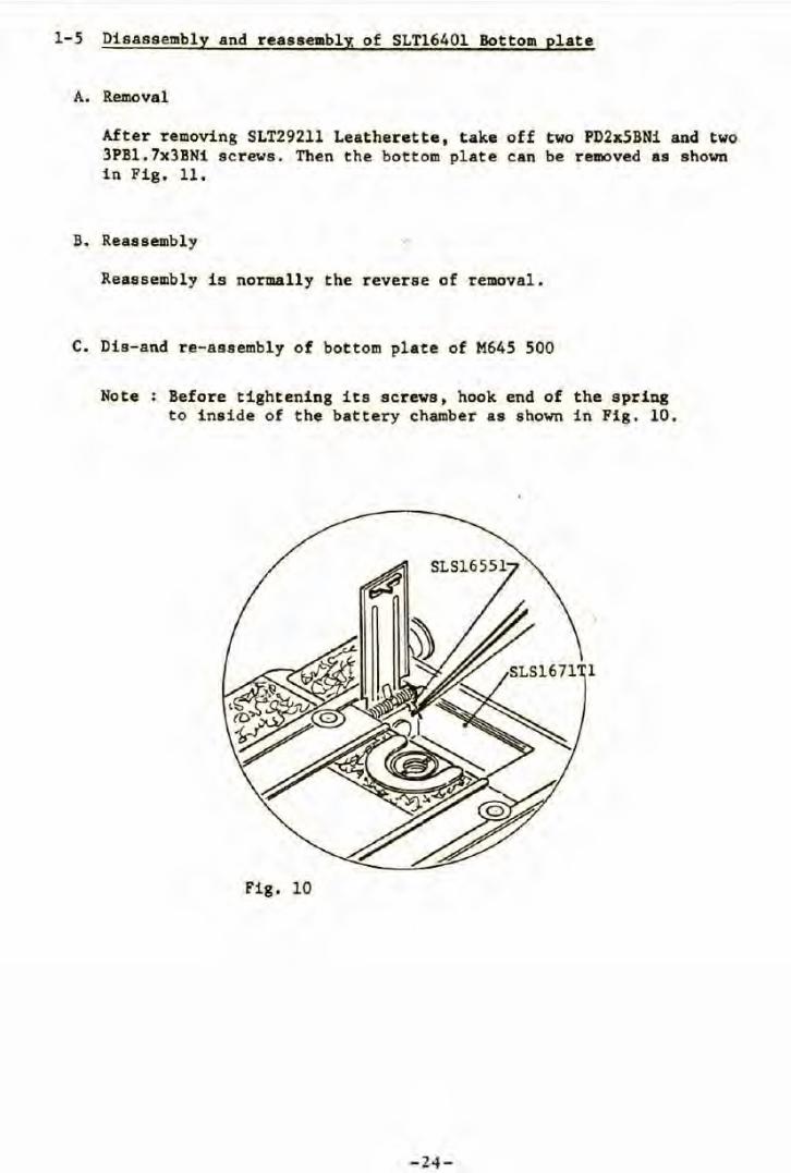
1-5 Disassembly and reassemblz of SLT1640l Bottom plate
A. Removal
After removing SLT292ll Leatherette, take off two PD2x5BNi and two 3PBl.7x3BNi screvs. Then the bottom plate can be removed as shown in Fig, ll,
B. Reassembly
Reassembly is normally the reverse of removal.
C. Dis-and re-assembly of bottom plate of M645 500
Note : Before tightening its screws, hook end of the spri~g to inside of the battery chamber as shown in Fig. 10.
Fig. 10
-24-
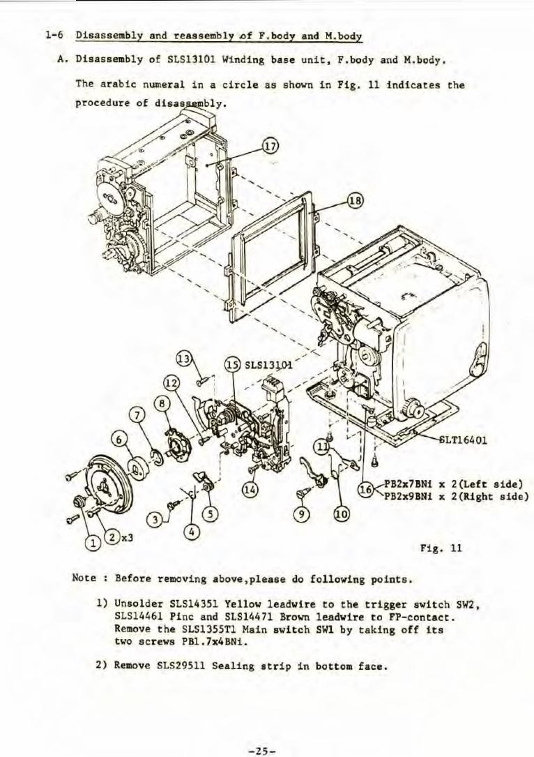
1-6 Disassembly and reassembly Df F.body and M.body
A. Disassembly of SLS13101 Winding base unit, F.body and M.body.
The arabic numeral in a circle as shown in Fig. 11 indicates the
procedure of
' '
PB2x7BNi x 2(Left aide) PB2x9BN1 x 2{Right side)
Fig. 11
Note : Before removing above,please do following points.
1) Unsolder SLS14351 Yellow leadwire to the trigger switch SW2, SLS14461 Pinc and SLS14471 Brown leadwire to PP-contact. Remove the SLS1355Tl Main switch SWl by taking off its two screws PBl. 7x4BNi.
2) Remove SLS29511 Sealing atrip in bottoa face.
-25-
B. Reassembly '
Reassembly is normally the reverse of disaasembly.
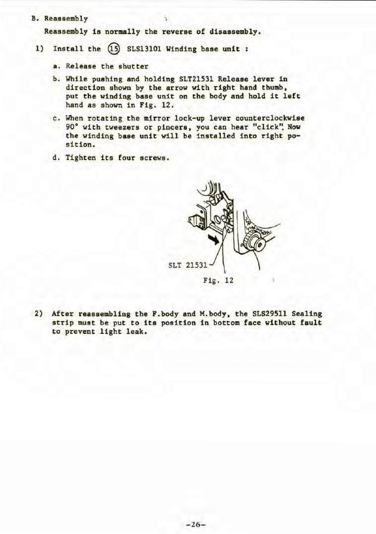
1) Install the @ SLS13101 Winding base unit :
a . Release the shutter
b. While pushing and holding SLT21531 Release lever in direction shown by the arrow with right hand thumb. put the winding base unit on the body and hold it lef t hand as shown in Fig. 12.
c. When rotating the mirror lock-up lever counterclockwise 90° with tweezers or pincera. you can hear "click'~ Now the winding base unit will be installed into right position.
d . Tighten its four screws.
SLT
Fig. 12
2) After reassembling the F.body and M. body. the SLS29511 Sealing strip must be put to its position in bottom face without fault to prevent light leak.
- 26-
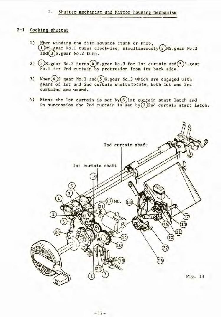
2. Shutter mechanism and Mirror housing mechanism
2-1 Cocking shutter
1) ,.J:Ltien winding the film advance crank or knob, \.!)M~ear No.l turns c l ockwise, s imultaneousl y(Î)MS.gear No.2
and\2.)S.gea r No.2 turn.
2) (î}s.gear No.2 turns~S.g~a r No.3 for J s t c urtain nnd~S.gear No.l fo r 2nd curtain by protrusion from its back side.
3) WhenG;)s.gear No.l and(I)s.gear No.3 which are engaged with gears of lst and 2nd curtain shaftsrotate, both lst and 2nd curtains are wound.
4) First the lst curtain is set by~lst c~ain start latch and in succession the 2nd curtain is set by\2.)2nd curtain start latch.
2nd curtaln shaf c
lst curtain shnft
- 27 -
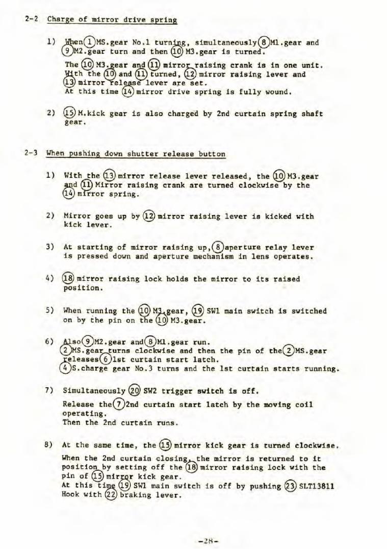
2-2 Charge of mirror drive spring
l) )llien(I)Ms.gear No.l turn~g, simultaneously~Ml.gear and ~M2.gear turn and thenQg>Ml.gear is turned.
The Qgl M3,.:-!ear and@mirrohraising crank is in one unit. ):l:S._th the ~and @ turned, Q3J mirror raising lever and ~mirror rel~e lever a~e set. At this time ~mirror drive spring is fully wound.
2) @M. kick gear is also charged by 2nd curtain spring shaft gear.
2-3 When pushing down shutter release button
1)
2)
3)
Wi th the @mirror release lever released, the @M3. gear ~d (Û) Mirror raising crank are turned clockwise by the ~ m'rr'ror spring.
Mirror goes up by @mirror raising lever is kicked with kick lever.
At starting of mirror raising up,{!)aperture relay lever is pressed down and aperture mechanism in lens operates.
4) @mirror raising lock holds the mirror to its raised position.
5) When running the@M)-.__gear, @sw1 on by the pi n on theQg}M3.gear.
main switch is switched
6) ~so~M2.gear and~Ml.gear run. ~S.gea~urns clockwise and then the pin of the(â)Ms.gear ~leases~lst curtain start latch. ~S.charge gear No.3 turns and the lst curtain starts running.
7) Simultaneously@ SW2 trigger switch is off.
Release the{Z)2nd curtain start latch by the moving coil operating. Then the 2nd curtain runs.
8) At the same time, the@mirror kick ge.ar is turned clockwise.
When the 2nd curtain closing the mirror is returned to it po.sition by setting off the~ mirror raising lock with the pin of@mirN kick gear. At this ti~ QJJ SWl main switch is off by pushing @stT13811 Hook with~braking lever.
-28-
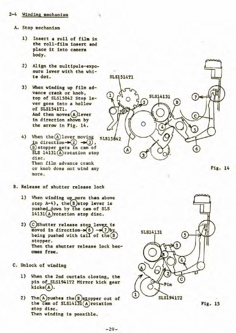
2-4 Winding mechanism
A. Stop mechanism
1) Insert a roll of fila in the roll-film insert and place it into camera body .
2) Align the multipule-exposure lever with the white dot.
3) When winding up film advance c rank or knob,
4)
top of SLS15842 Stop lever goes into a hollow of SLS1541Tl. And then movea~lever in direction shown by the arrow in Fig . 14.
When the@lever moving .J...n direction~ ~, ~stopper .,s._ets in cam of SLS 1413l~rotation s top dise. Then film advance crank or knob does not wi nd any more.
B. Releaae of shutter releaae l ock
l) When winding u~re than above s tep A-4), t he\!}stop lever is puahed down by the cam of SLS 1413l~rotation stop dise.
2) (S}shutter releaae~to lev~is moved in directio 6 ~~ being pushed with tai of t he \!} s topper . Then t he shutter release lock bec-oraes free.
C. Unlock of winding
l) When the 2nd curtain closing, the pin o~LS1941T2 Mirror kick gear kicks~.
2) The~puahes the6iJ~pper out of the cam of SLS14iji~rotation stop dise . Then winding is possible .
-29-
Fig. 14
SLS14131
Fig. 15
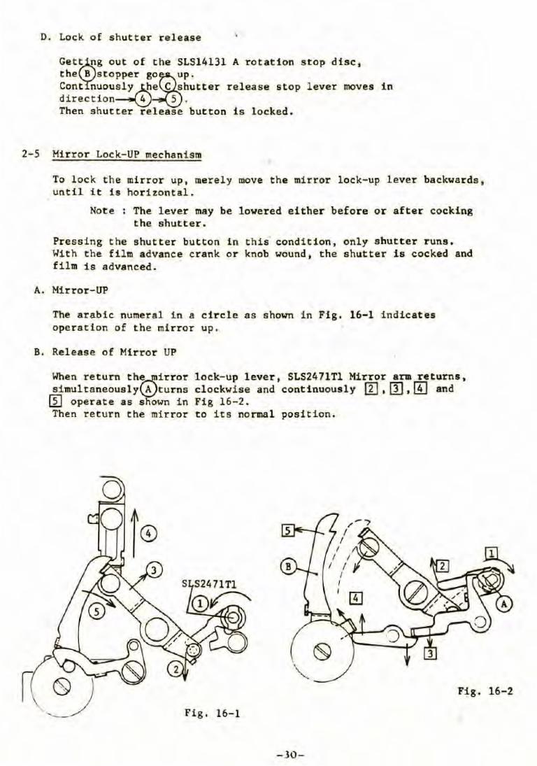
D. Lock of shutter release
Get~ng out of the SLS14131 A rotation stop dise, the B stopper go~p. Cont nuously~e C shutter release stop lever moves in direction~ 5 . Then shutter release button is locked .
2-5 Hirror Lock-UP mechanism
To lock the mirror up, merely move the mirror lock-up lever backwards, until it is horizontal.
Note : The lever may be lowered either before or after cocking the shutter.
Pressing the shutter button in this condition, only s hutter runs. With the film advance crank or knob wound, the shutter is cocked and film is advanced.
A. Hirror-UP
The arabic numeral in a circle as sholll\ in Fig . 16-1 indicates operation of the mirror up.
B. Release of Hirror UP
When return th~irror lock-up lever, SLS2471Tl Hirror ara returns, simultaneouslyl.t)turns clockwise and continuously m. m' [!] and
[il operat e as shown in Fig 16-2. Then return the mirror to its nonnal position .
Fig . 16-2
Fig. 16- 1
-30-

C. Replacement of mirror
1) Removal
Remove SLS24151 Retaining spring by taking off two PB1.4xl.8BN1 screws as refering to the parts catalog page 4. Then the mirror can be removed.
2) Attaching
Attach the mirror carefully, not to put your fingerprints and scratches on it . After that check mirror angle 45° by refering to 6-2.
-31-
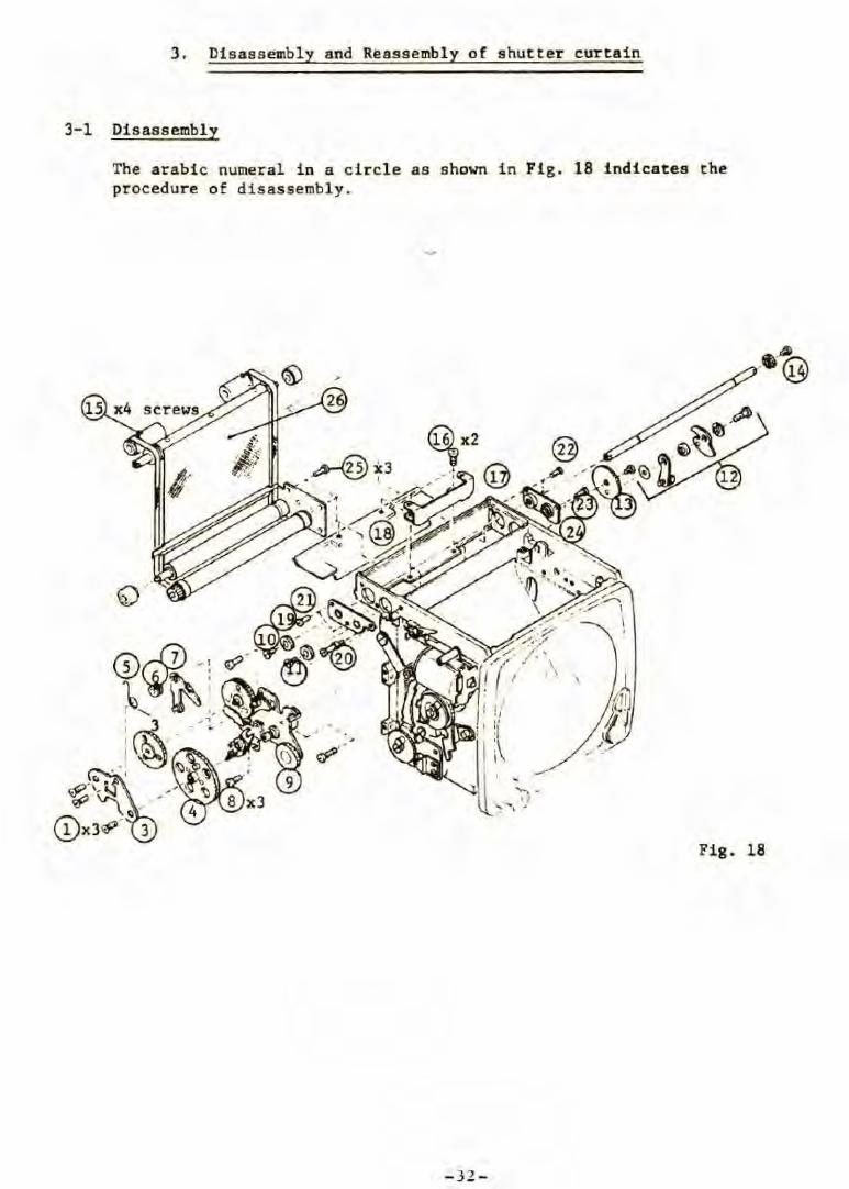
3. Di sass embly and Reassembly of shutter curta in
3-1 Disassembly
The arabic numeral in a cir cle as shown in Fig. 18 indicates the procedure of di sassembly.
~·
Fig . 18
- 32-
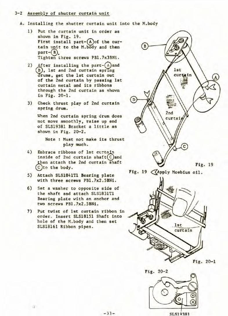
3-2 Assembly of s hutter curtain unit
A. Installing the shutter curtain unit i nto the M. body
1) Put the curtain unit in order as shown i n Fig. 19. First install part-~of the curta in unit to the M.body and then part-@, Tighten three sc rews PBl.7x3BNi .
2) Aft er install ing t he part-rAland (8) , lst and 2nd curtain sp~g 'è(rums, get the lat curtain out of the 2nd curtain by passing lst cur tain metal and its ribbons through t he 2nd curtain as shown in Fig . 20-1.
3) Check thrust play of 2nd curtain spring drum.
4)
5)
When 2nd curtain spr i ng drum does not move smoothly, raise up end of SLS19381 Bracket a little as shown in Fig. 20-2 .
No t e : Must not make its thrust play much.
Embrace ribbons of lst c~~t~ i nside of 2nd cur tain shaf t\S)and ~en at tach t he 2nd curtain shaft \S)to the body.
Attach SLS1841Tl Bearing plate with three s crews PBl.7x2 . 5BNi .
6) Set a washer to opposite s i de of the shaft and attach SLS1831Tl Beari ng plate with an anchor and t wo screws PBl.7x2.5 BNi .
7) Put twist o f lst curtain r ibbon in order . lnsert SLS18151 Shaft into hole of the M.body and then set SLS18161 Ribbon pipes.
,.
- 33 -
Fig. 19
Fig. 20-2
SLS19381
Fi g. 19
oi l.
Fig. 20-1
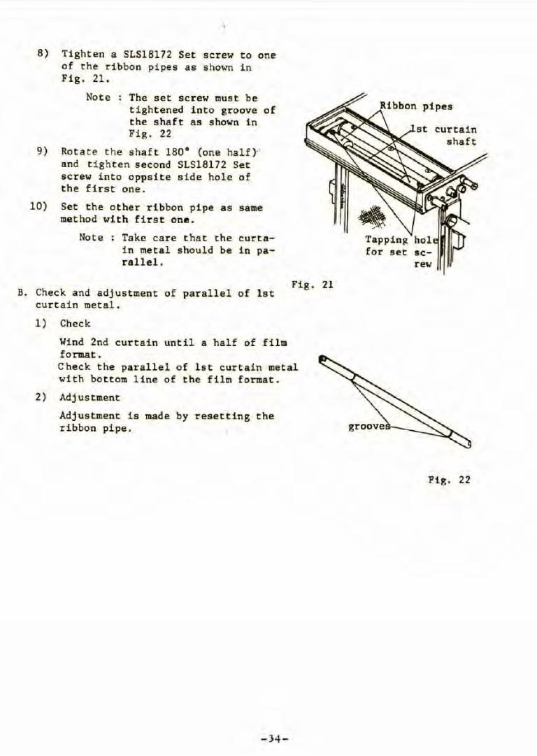
8) Tighten a SLS18172 Set screw to one of the ribbon pipes as shown in Fig. 21.
Note : The set screw must be tightened into groove of the shaft as shown in Fig. 22
9) Rotate the shaft 180° (one half) · and tighten second SLS18172 Set screw into oppsite side hole of the first one.
10) Set the other ribbon pipe as same method with first one .
Note : Take care that the curtain metal should be in parallel.
B. Check and adjustment of parallel of lst curtain metal.
1) Check
Wind 2nd curtain until a half of film format.
Fig. 21
Check the parallel of lst curtain metal with bottom line of the film format.
2) Adjustment
Adjustment is made by resetting the ribbon pipe.
-34-
screw
curtain shaft
Fig. 22
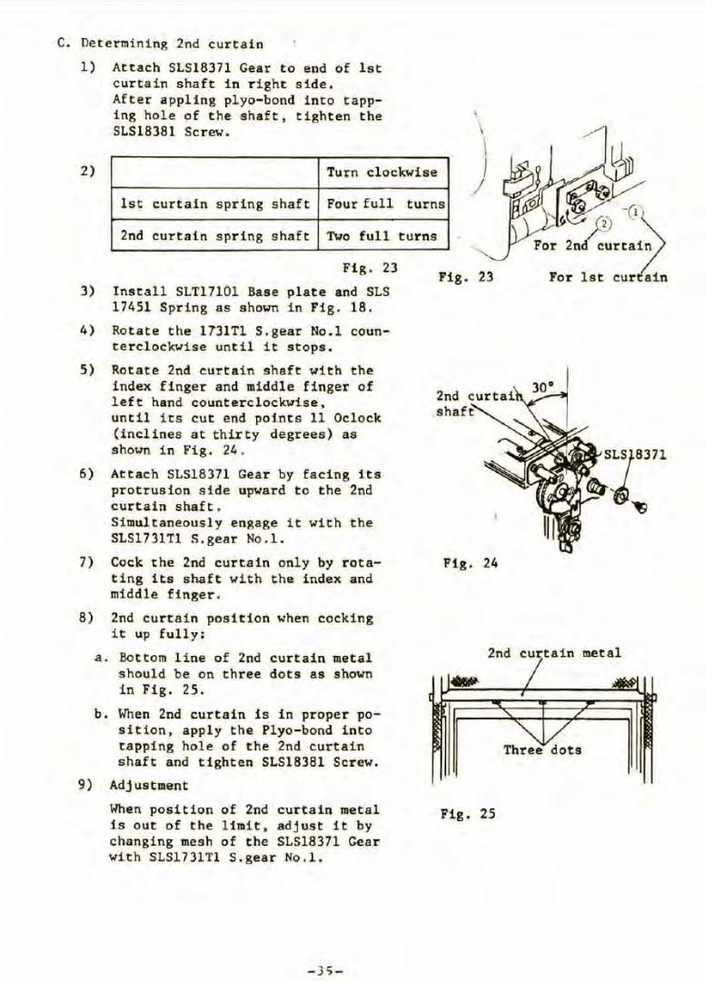
C. Det ermining 2nd curtain
1) Attach SLS18371 Gear to end of lst curtain shaft in right side.
2)
Aft er appling plyo-bond into tapping hole of t he shaft, tighten the SLS18381 Sc rew .
Turn clockwise
\
\ \ 1
/ l st curtain spring shaf t Four full turns
2nd curtain spring shaf t Two full turns
Fig. 23
3) Install SLT17101 Base plate and SLS 17451 Spring as shown in Fig. 18.
4) Rotate the 1731Tl S.gear No.l counterclockwise until it stops.
5) Rotate 2nd curtain shaft with the index f i nger and middle f inger of left hand counterclockwise , until its eut end pof.nts 11 Oclock (inclines at thirty degrees) as shown in Fig. 24.
6 ) Attach SLS18371 Gear by facing its protrusion side upward to the 2nd curtain shaft. Simultaneously engage i t with the SLS1731Tl S.gear No.l .
7) Cock the 2nd curtain only by r otating its shaft with the index and middle finger.
8) 2nd curtain position when cocking i t up fully:
a. Bottom l ine of 2nd curtain metal should be on three dots as shown in Fig. 25.
b. When 2nd curtain is in proper position, apply the Pl yo-bond into tapping hole of the 2nd curtain shaft and tighten SLS18381 Screw.
9) Adjustment
When position of 2nd curtain metal i s out of the l imit, adjust it by changing mesh of the SLS18371 Gear with SLS1731Tl S. gear No.l.
- 35-
Fig. 23
Fig. 24
2nd cur tain metal
Three dots
Fig. 25
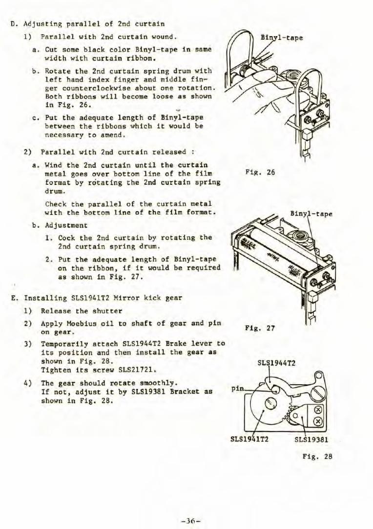
D. Adjusting paral lel of 2nd cur tain
1) Parallel with 2nd curtain wound.
a. Cut some black color Binyl- tape in same width with curtain r ibhon.
b. Rotate the 2nd curtain spring drum with left hand index finger and midd le finger counterclockwise about one rotation. Both ribbons will become l oose as shown in Fig . 26.
c. Put the adequate length of Binyl-tape between the ribbons which it would be necessary to amend.
2) Parallel with 2nd curtain released :
a. Wind t he 2nd curtain until the curtain metal goes over bottom l ine of the film forma t by rôtating the 2nd curtain spring drum.
Check the parallel of the curtain metal with the bottom line of the film format.
b . Adjustment
1. Cock the 2nd curtain by rotating the 2nd curtain spring drum.
2. Put the adequate length of Binyl-tape on the ribbon, if it would be required as shown in Fig. 27.
E. Installing SLS1941T2 Mirror kick gear
1) Release the shutter
2)
3)
4)
Apply Moebius oil to shaft of gear and pin on gear.
Temporarily attach SLS1944T2 Brake lever to its position and then install the gear as sho\o1Tl in Fig. 28. Tighten its screw SLS21721.
The gear sbould rotate SlllOOthly. If not, adj ust it by SLS19381 Bracket as shown in Fig. 28 .
-36-
Fiit. 26
-tape
Fig. 27
SLS1944T2
SLS1941T2 SLS19381
Fig. 28
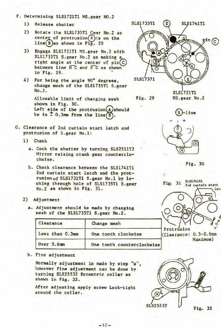
F. Determining SLS1721Tl MS.gear N0.2
1)
2)
3)
Release shutter
Rotate the SLS1735Tl GeAr No.2 as cent~of [email protected] on the line\!)as shown in Fig. 29
Enga~e SLS1721Tl MS.gear No.2 with SLS1735Tl S.gear No.2 as making a right angle at~the center of pin~ between line D C and E C as shown in Fig. 29. -
4) For being the angle 901 degrees, change mesh of the SLS1735Tl S.gear No.2.
Allowable limit of changing mesh Fig. 29 shown in Fig. 30. Left side of the protrusionG)should be in ! 0.3mm from the line~ .
G. Clearance of 2nd curtain start latch and protrusion of S.gear No.l:
l) Check
a. Cock the shutter by turning SLS2511T2 Mirror raising crank gear counterclockwise.
b. Check clearance between the SLS1741Tl 2nd curtain start latch and the protrusion of SLS1731Tl S.gear No.l by looking through hole of SLS1735Tl S.gear No.2 as shown in Fig. 31.
2) Adjustment
a. Adjustment should be made by changing mesh of the SLS1735Tl S.ge.ar No.2.
Clearance Change mesh
Less than 0.3nun One tooth clockwise
Over 0.6mm One tooth counterclockwise
b. Fine adjustment
Normally adjustment in made by step "a", however fine adjustment can be done by turning SLS25532 Eccentric collar as shown in Fig. 32.
After adjusting apply screw Lock-tight around the collar,
-37-
..,-
Fig.
SLS1721Tl MS.gear No.2
@-1tne
1 +
Fig. 3U
SLS1741Tl 31 2od c ruin •tort
lac<
0.3-0.6mm Maximum)
Fig. 32
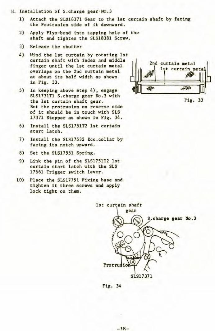
H. Installation of S.charge gear • N0.3
1) Attach the SLS18371 Gear to the lst curtain shaft by facing the Protrusion side of i t downward.
2) Apply Plyo-bond tnto tapping hole of the shaft and tighten the SLS18381 Screw.
3) Release the shutter
4)
5)
llind the lst curtain by rotating lst curtain shaft with index and middle finger until the ls t curtain metal overlaps on the 2nd curtain metal at about its half width as shown in Fig . 33.
I n keeping above step 4), engage SLS1731Tl S.charge gear No.3 with the lst curtain shaft gear. But the protrusion on reverse side of it should be in touch with SLS 17371 Stopper as shown in Fig. 34.
6) Install the SLS1751T2 lst curtain start latch.
7) Install the SLS17532 Ecc . collar by facing its notch upward.
8) Set the SLS17551 Spring.
9) Link the pin of the SLS1751T2 lst curtain s tart latch with the SLS 17661 Trigger switch lever .
10) Place the SLS17751 Fixing base and tighten it three acrews and apply lock tight on t hem.
lst curtain shaft
2nd
SLS17 371
Fig . 34
-38-
curtain 111etal 1 t curtain mecal
. ~ .,.,.
Fig . 33
gear No,3

11) Recheck
Wind the shutter slowly a.nd check as follows .
a.
b.
c.
First the lst curtain satrt lat ch should be set with sound "click".
Next the 2nd curtain start lat ch should be set.
Finally the SLS2551Tl Mirror release crank lever should be set.
curtain start latch
curtain start latch
kick lever
Fig. 35
With the SLS2511T2 Mirror raising crank counterclockwise wound, lst and 2nd curtains are cocked as well as the mirror drive spring.
When releasing the SLS2551Tl Mirror release lever and then the Mirror kick lever, the mirror drive spring and lst curtain run.
When releasing the 2nd curtain start latch, the 2nd curtain runs.
-39-
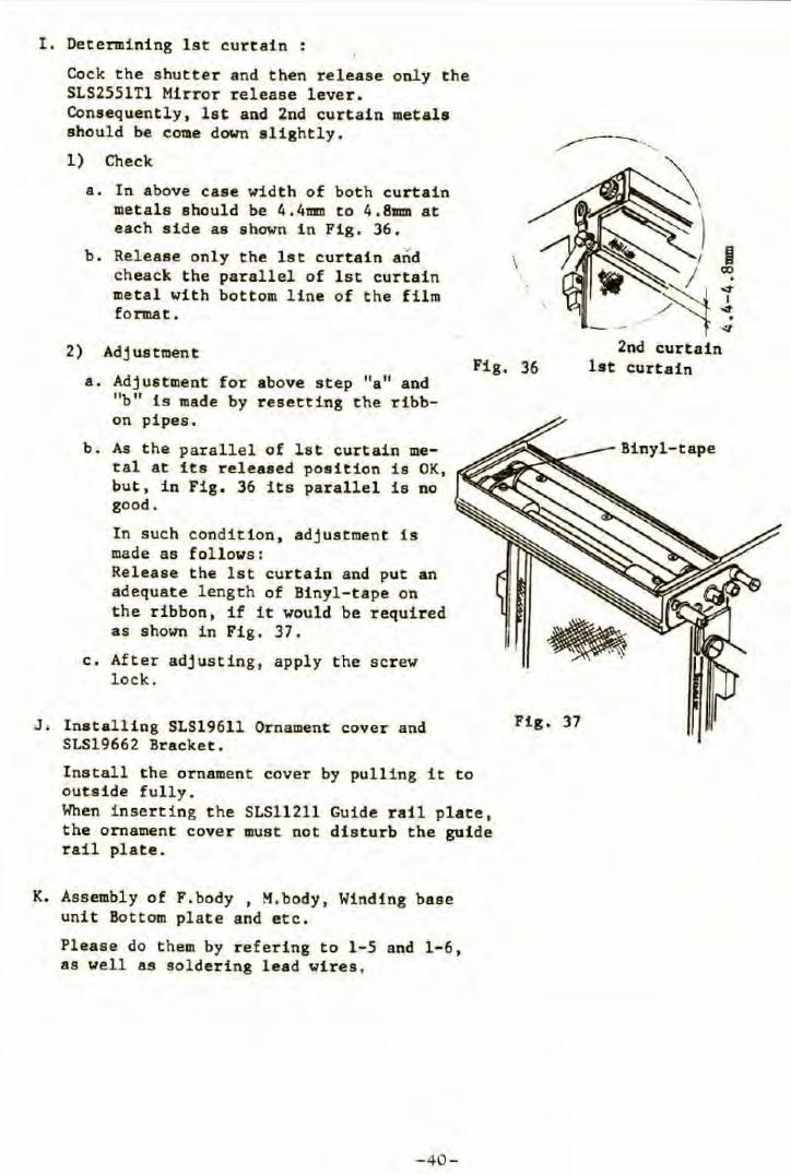
I. Determining lst curtain :
Cock the shutter and then r e l ease only the SLS2551Tl Mirror release lever. Consequently , let and 2nd curtain metals should be COiie down slightly.
1) Check
a. In above case width of both curtain metals ahould be 4.4111D to 4. 8mm at each side as shown i n Fig. 36.
b. Releaae only the ls t curtain and \ cheack the parallel of lst curtain metal with bottom line of the film format.
2) Adj uatment
a. Adjus tment for above step "a" and "b" is made by resett ing the ribbon pipes.
b. As the parallel of lst curtain metal at its released position is OK, but, in Fig. 36 its parallel is no good .
In such condition , adjustment is made as follows: Releaae t he lst curtain and put an adequate length of Binyl-tape on the ribbon, if it would be required as shown in Fig. 37 .
c. After adjusting, apply the scr ew lock.
Fig. 36
,,..,.....--....
2nd curtain lst curtain
J. lnstalling SLS19611 Ornament cover and SLS19662 Bracket .
Fig, 37
Install the ornament cover by pul l ing i t to outsi de fully. When i nser ting t he SLS11211 Guide rail plate, the ornament cave r must not disturb the guide rail plate.
K. Assembly of F.body , M.body, Wind ing base unit Bottom plate and e tc.
Please do them by refering to 1-5 and 1-6, a s well as soldering lead wires.
-40-
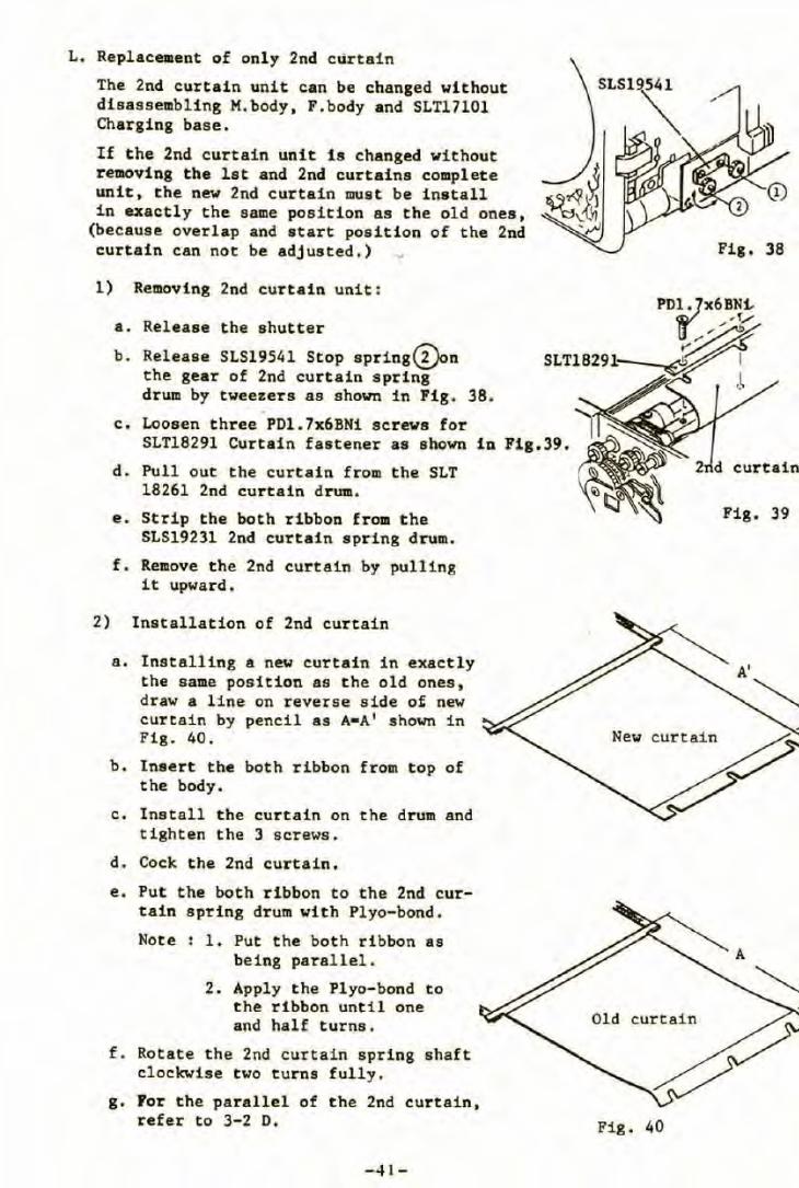
L. Replacement of only 2nd cûrtain
The 2nd curtain unit can be changed without disassembling M.body, F.body and SLT17101 Charging base.
If t he 2nd curtain unit is changed without removing the lat and 2nd curtains complete unit, the new 2nd curtain must be install in exactly the same position as the old ones,
(because overlap and start position of the 2nd curtain c·an not be adjusted.) .,
l) Removing 2nd curtain unit:
a. Release the shutter
b. Release SLS19541 Stop spring<â)on the gear of 2nd curtain spring
. c. Loosen three PD1.7x6BN1 screws for
SLT18291 Curtain f astener as shown
d. Pull out the curtain from the SLT 18261 2nd curtain drum.
e. Strip the both ribbon from t he SLS19231 2nd curtain spring drum.
f. Remove the 2nd curtain by pulling it upward.
2) Installation of 2nd curtain
a. Installing a new curtain in exactly the same position as the old ones, draw a line on reverse aide of new curtain by pencil as A•A' shown in Fig. 40.
b. lnsert the both ribbon from top of the body.
c. Install the curtain on the drum and tighten the 3 screws.
d. Cock the 2nd curtain.
e. Put the both ribbon to the 2nd curtain spring drum with Plyo-bond.
Note : 1 . Put the both ribbon as being parallel.
2. Apply the Plyo-bond to the ribbon until one and half turns.
f . Rotate the 2nd curtain spring shaft clockwise two turns fully.
g. For the parallel of the 2nd curtain , refer to 3-2 D.
-41-
Fig. 38
Fig . 39
Fig. 40
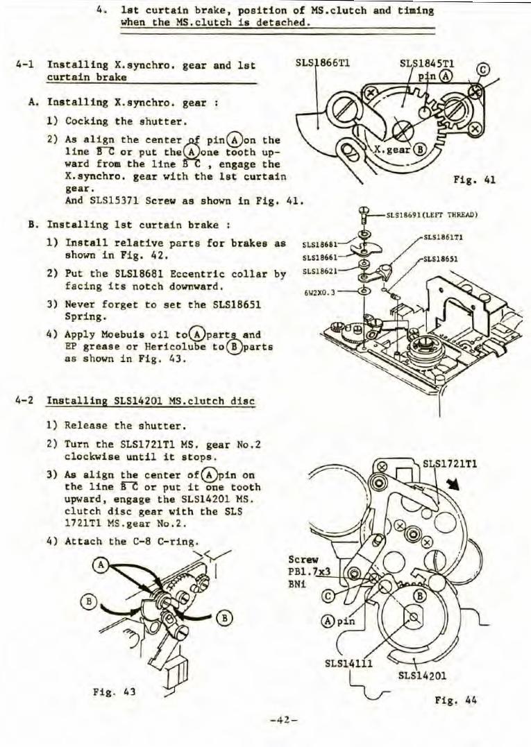
4. lat curtain brake, position of MS.clutch and timing when the HS.clutch ia detached.
4-1 Installing X.synchro. gear and let curtain brake
A. Installing X.synchro . gear :
1) Cocking the shutter.
2) As align the center~ pin~on the line 1r'C or put the A one tooth upward from the line , engage the X.synchr o . gear with t he lat curtain gear.
SLS 866Tl
And SLS15371 Serew as shown i n Fig. 41.
B. Installing lst eurtain brake :
1) Instal l relative parts for brakes as shown in Fig. 42.
2) Put the SLS18681 Eecent rie collar by facing its notch downward.
3) Never forget to set the SLS18651 Spring .
4) Apply Moebuis oil to~par~and EP grease or Hericolube to\!}l>arts as shown in Fig. 43.
4- 2 Installing SLS14201 MS.clutch dise
1) Release the shutter.
2) Turn the SLS1721Tl MS. gear No.2 eloekwise until it 1tops.
3) As align the eenter of~in on the line fi"-e or put it one tooth upward, engage the SLS14201 MS. clutch dise gear with the SLS 1721Tl MS.gear No.2.
4) Attaeh the C-8 C-ring. "<).,/ ~,
SLS1·4111
Fig. 41
~ SLS14201
Fig . 43 Fig. 44
-42-
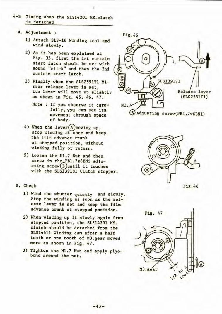
4-3 Timing when the SLS14201 MS.clut ch is detached
A. Adjustment :
1) Attach SLS-18 Winding t ool and wind alowly.
2) As it has been explained at Fig. 35, first the lst curtain s tar t latch should be set with sound "cl ick" and then the 2nd curtain start latch .
3) Finally when the SLS2551Tl Mi rror releas e lever is set, its l ever will 1110ve up s l ightly as shown i n Fig . 45. 46. 47.
Note : If you observe it care-fully, you can see its movement t hrough space of body.
4) When the lever~oving up, stop winding at once a nd keep the film advance crank at s t opped posi tion, without winding fully or return .
5) Loosen the Nl . 7 Nut and then screw in the PBl.7x6BNi adjus t ing screwrBluntil it touches with the SLSî391Sl Clutch stopper .
B. Check
1) Wind the shutter quietly and s lowly. Stop the winding as soon as the release lever is set and keep the film advance crank a t stopped position.
2) When winding up i t slowly again from stopped position, the SLS14201 MS. clut ch s hould be detached from the SLS14611 Winding cam aft e r a ha l f t ooth or one t ooth of M3 .gear moved more as shown in Fig. 47 .
3) Tighten the Nl.7 Nut and apply plyobond around the nut .
-43 -
Releas e lever (SLS255lîl)
screw(PBl.7x6BNi)
Fig.46
Fig. 4 7
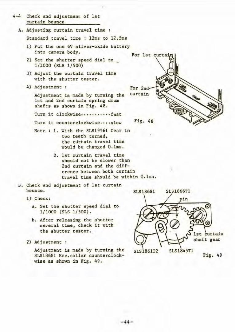
4-4 Check and adjustment of l st curtain bounce
A. Adjusting curtain travel time
Standard travel time : 12ms to 12.Sms
1) Put the one 6V silver- oxide bat tery i nto camera body.
2) Set the shutter speed dia~ to ~ 1/1000 (SLS 1/500)
3) Adjust the curtain travel time with the shutter tester.
For
4) Adjustment : For 2nd
Adjus t ment is made by turning the curtain lst and 2nd curtain spring drum shafts as shown in Fig. 48.
Turn it clockwise · ·· ···· ··· · fast
Turn it countercl ockwise····slow
Note : 1. With the S1Sl9561 Gear in two teeth turned , the cùrt ain travel time would be changed O.lms.
Fig, 48
2. lst curtain travel time should not be s l ower t han 2nd curtain and the difference between both curtain travel time should be within O. lms.
B. Check and adjustment of lst curtain bounce.
1) Check:
a. Set t he shutter speed dial to 1/1000 (S1S 1/500).
b . After releasing the shutter several time, check it with the shutter tester .
2) Adj us t ment :
Adjustment is made by turning the S1518681 Ecc.collar counterclockwi se as shown in Fig . 49 .
- 44-
SLS18681
SLS1861T2
SLS1866Tl
S1Sl845Tl Fig . 49
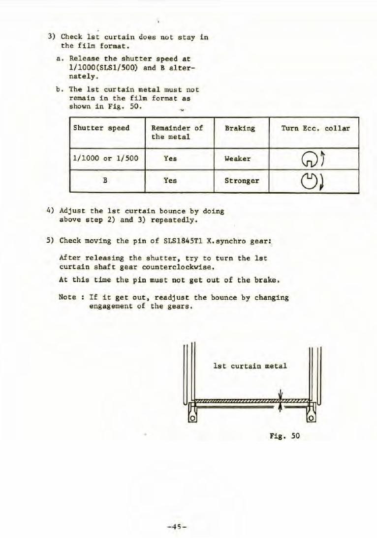
3) Check lst curtain does not stay in the film format.
a. Release the shutter speed at l/lOOO(SLSl/500) and B alternately.
b. The lst curtain metal must not remain in the film format as shown in Fig . 50.
Shutter speed Remainder of Braking Turn Ecc. collar the metal
1/1000 or 1/500 Yes
B Yes
4) Adjust the lst curtain bounce by doing above step 2) and 3) repeatedly.
Weaker
St ronger
5) Check moving the pin of SLS1845Tl X. synchro gear:,
After releas i ng the shutter, try to turn the lst curtain shaft gear counterclockwise.
At this time the pin must not get out of the brake.
Note : If it get out, readjust the bounce by changing engagement of the gears.
lst curtain metal
0
Fig. 50
-45-
Q~ c:J)
0
5-1
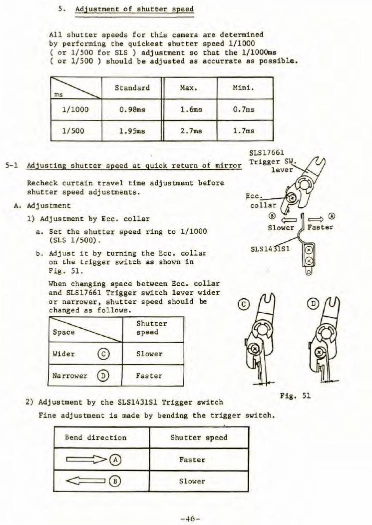
5. Adjustment of shutcer speed
All shutter speeds for this camera are determined by performing the quickest shutter speed 1/1000 ( or 1/500 for SLS ) adjustment so that the l/lOOOms ( or 1/500 ) should be adjusted as accurrate as possible .
~ Standard Max. Mini.
1/1000 0 . 98ms l.6ms 0.7ms
1/500 l.95ms 2. 7ms l.7ms
Adjusting shutter speed at quick return of mirror
SLS17661 Trigger SW.
lever
Recheck curtain travel tim.e a djuscment before shutter speed adjustments.
A. Adjustment
1) Adjustment by Ecc . collar
a . Set the shutter speed ring to 1/1000 (SLS 1/500).
b. Adjusc it by turning the Ecc . collar on the trigger switch as shown in Fig. 51.
When changing space between Ecc . collar and SLS17661 Trigger switch lever wider or narrower, shutter speed should be @ changed as follows .
Wider @ Narrower @
Shutter speed
Slower
Fas ter
2) Adjuscment by the SLS1431Sl Trigger switch
SLS14
Fine adjustment is made by bending the trigger switch .
Bend direction Shutter speed
c::==>@ Fas ter
~@ Slower
-46-
0
Fig. 51
\
3) Adjustment by changing overlap of lst curtain
a. If it is impossible to adjust by step 1) and 2), change the overlap of lst curtain metal to the 2nd curtain metal by resetting the ribbon pipes of the lst curtain as shown in Fig. 52. ,.
Note : Please refer to 3-2 to do it. But disassembly F.body and M.body is not necessary.
b . If t he overlap of lst curtain metal is changed, the shutter travel time must be adjusted before shutter speed adjustment.
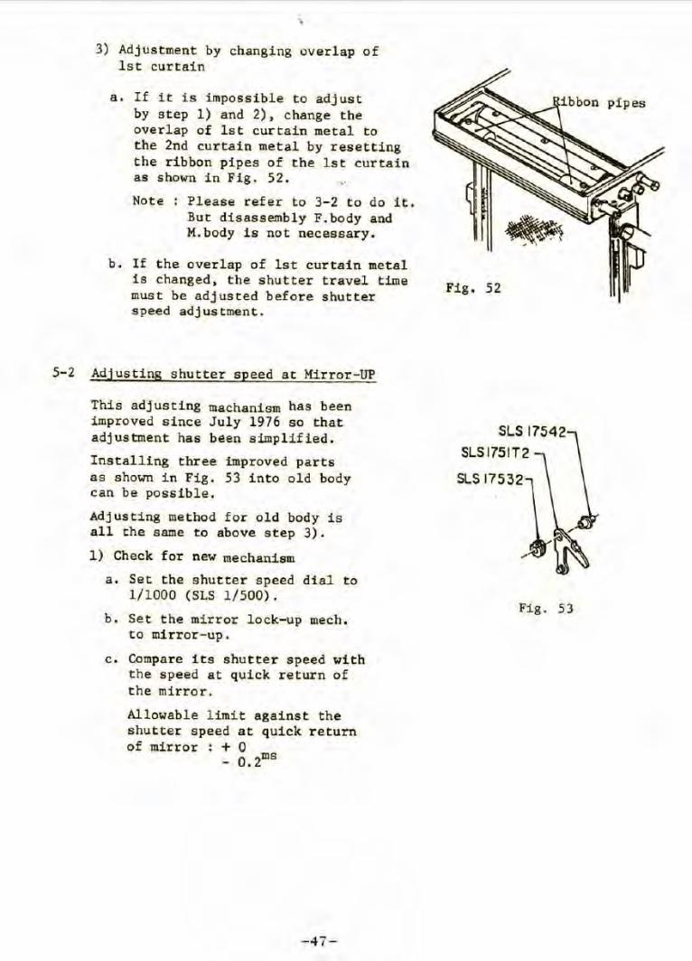
5- 2 Adjusting shutter speed at Mirror-UP
This adjusting machanism has been improved since July 1976 so that adjustment has been simplified .
Installing three improved parts as shown in Fig. 53 into old body can be possible.
Adjusting method for old body is all the same to above step 3).
1) Check for new mechanism
a. Set the shutter speed dial to 1/1000 (SLS 1/500).
b. Set the mirror lock-up mech . to mirror-up.
c. Compare its shutter speed with the speed at quick return of the mirror.
Allowable limit against the shutter speed at quick return of mirror : + 0
- 0.2ms
-47-
Fig. 52
SLS17542
SLSl751T2
SLS 17532
Fig. 53
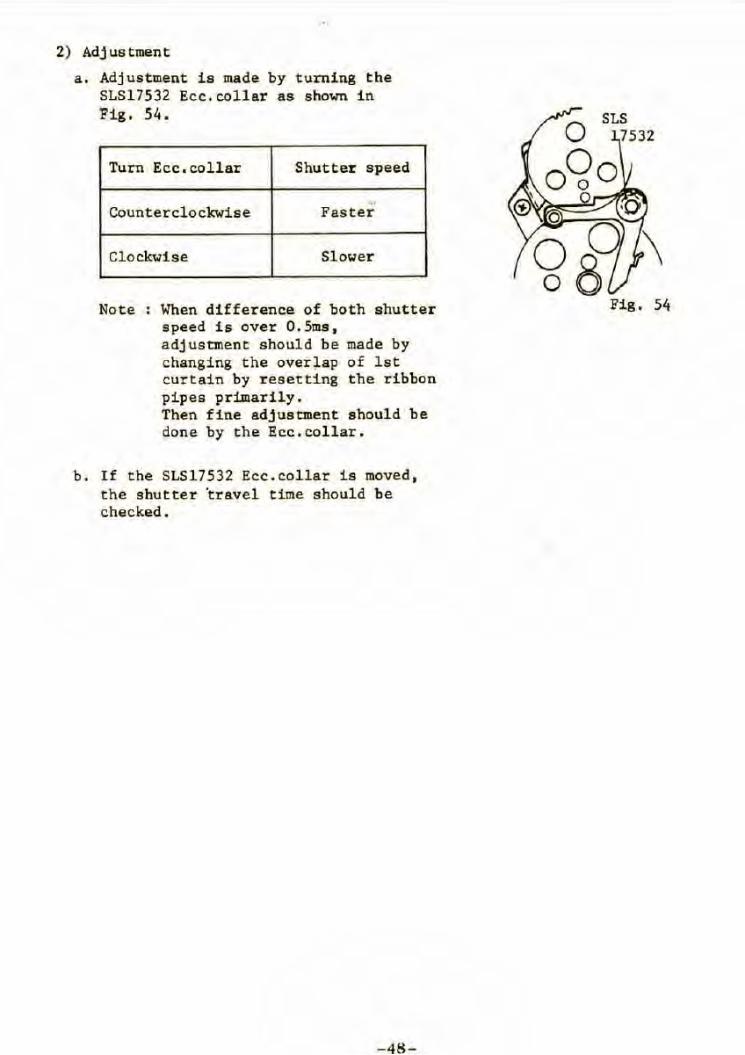
2) Adjustment
a . Adjustment i s made by turning the SLS17532 Ecc.col lar as shown in Fig . 54 .
Turn Ecc . coll ar Shutter speed
,. Counterclockwise Fas ter
Cl ockwise Slower
Note When di fference of both shutter speed is over O.Sms, adj ustment shoul d be made by changing the over1ap o f lst curtain by r esetting the ribbon pipes pr imari ly. Then fine adjus tment s hould be done by t he Ecc . collar .
b . I f the SLS 17532 Ecc . collar is moved, t he shutter 'trave l time should be checked .
- 48 -
Fig, 54
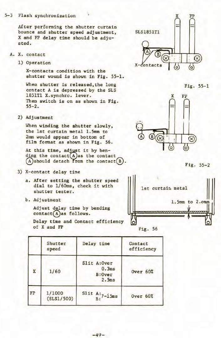
5-3 Flash synchronization
After performing the shutter curtain bounce and shutter speed adjustment, X and FP delay time should be adjusted .
A. X. contact
1) Operation
X-contacts condition with the shutter wound is shown in Fig. 55-1 .
When shutter is released,the long contact A is depressed by t he SLS 1851Tl X.synchro. lever. Then switch is on as shown in Fig . 55-2.
2) Adjustment
When winding the shutter slowly, the lst curtain metal l.5mm to 2uun would appear in bottom of film format as shown in Fig. 56.
At this time, ad~t it by ben-ding the contact A as t he contact ~should detach rom the contacte!).
3) X-contact delay time
a. After setting the shutter speed dial to l/60ms , check it with shutter tester.
b. Adj ustment
Adjust delay time by bending contact~as follows .
Delay time and Contact efficiency of X and FP
Shutter Delay time speed
Slit A:Over
X 1/60 0.3ms B:Over
2.5ms
FP 1/1000 Slit A. . (SLSl/500) 8 ;7- 15ms
-49-
X FP
SLS1851Tl
X-
Fig. 55-1
X FP
A
Fig. 55-2
lst curtain metal
1. 5mm to 2 . oram
0 0
Fig. 56
Contact efficiency
Over 60%
Over 60%
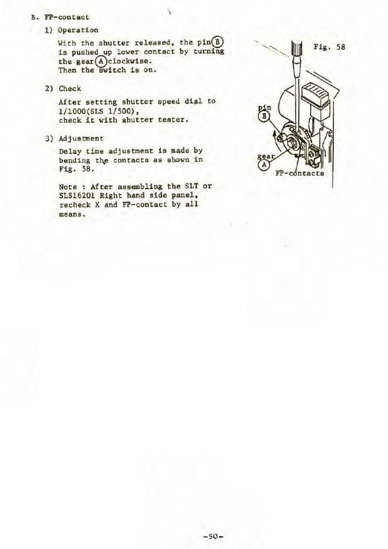
B. PP-contact
1) Operation
With the s hut ter released, t he pin~ is pushed up lower contact by turning the gear~clockwise. Then the switch is on.
2) Check
After s etting shutte r speed dial to l /lOOO(SLS 1/500), check i t with shutter tester .
3) Adjuscment
Delay time adjus tment i s made by bending t~e contacts as shown in Fig . 58 .
Not e : After assembli ng the SLT or SLS16201 Right hand s ide panel , r echeck X and FP-contact by all means.
- 50 -
.. Fig. 58
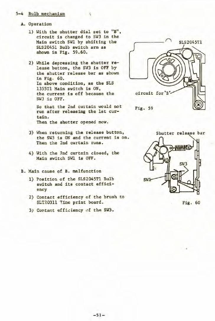
5-4 Bulb mechanism
A. Operation
1) With the shutter dial set to "B" , circuit is changed to SW3 in the Main switch SWl by shifting the SLS20451 Bulb switch arm as shown in Fig . 59 . 60.
2) Whi le depressing the shutter release button , the SW3 is OFF by the shut ter r elease bar as shown in Fig . 60. ln above condition, as the SLS 1355Tl Main switch is ON, the curr ent is off because the SW3 ic OFF.
So that the 2nd curtain would not run after r eleasing the lat curtain. Then the shutter opened now.
3) When returni ng the release button , the SW3 is ON and the current is on . Then the 2nd curtain runs.
4) With the 2nè curte.in ci osed, the Main switch SWl is OFF .
B. Main cause of B. malfunction
l) Position of the SLS2045Tl Bulb switch and its contact efficiency
2) Contact effici ency of the brush to SLT.~0311 Ti.l:lc p·r int boarc! .
3) Conta.~t effi.::iency 1)f thP. SW3 .
-5 1-
______ ri SLS2045Tl
Fig . 59
Fig . 60
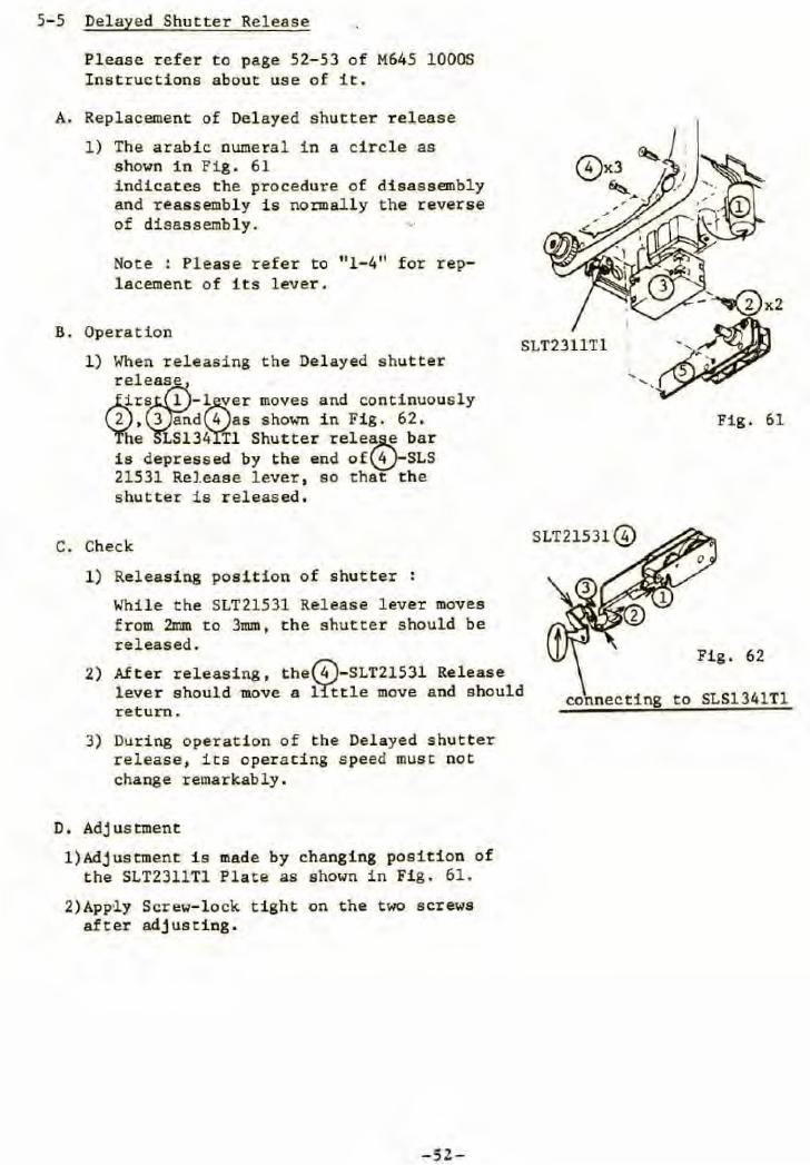
5-5 Delayed Shutter Release
Please refer to page 52-53 of M645 10005 Ins tructions about use of it.
A. Replacement of Delayed shutter release
1) The arabic numeral in a circle as shown in Fig. 61 indicates the procedure of disassembly and reassembly is normally the reverse of disassembly. •·
Note : Please refer to "l-4" for replacement of its lever.
B. Operation
l ) When releasing the Delayed shutter
rel~es i r e l -l~er moves and continuously
, 3 and 4 as shown in Fig. 62 . he LS134 Tl Shutter rele~ bar
is depressed by the end of\!!j-SLS 21531 Rel.esse lever, so that the shutter is releas ed.
C. Check
l) Releasing position of shutter :
While the SLT21531 Rel ease l ever moves from 2mm to 3mm, the shutter should be released.
2) After releasing, the~-SLT21531 Release lever should move a ~tle move and should return.
3) During operation of the Delayed shutter r elease, its operating speed must not change remarkably .
D. Adj us tment
l)Adjustment is made by changing position of the SLT2311Tl Plate as shown in Fig. 61.
2)App~y Screw-lock tight on t he t wo screws after adjusti.ng.
-52-
Fig. 61
Fig. 62
connecting to SLS1341Tl
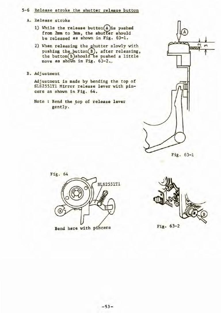
5-6 Release stroke the shutter release button
A. Release stroke
1) While the rel ease button~is pushed f r om 2mm to 3mm, the shutter should be released as shown in Fig . 63- 1 .
2) When releasing the~utter slowly with pushing the button B , after releasing, the button~should e pushed a little move as shown in Fig. 63-2 .v
B. Adjustment
Adjustment is made by bending the top of SLS2551Tl Mirror release lever with pincers as s hown in Fig. 64.
Note Bend the ,top of release lever gently.
Fig. 64
Bend here with pincer a
-53-
N M
Fig. 63-1
Fig. 63-2
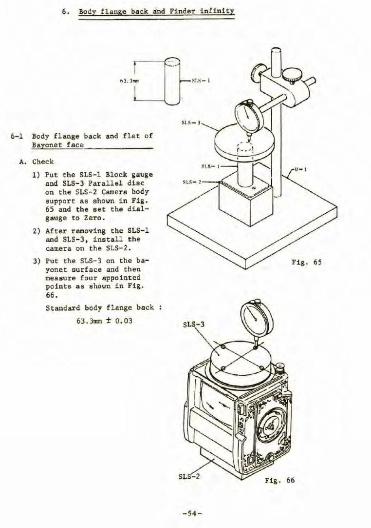
6. Body flange back a~d Pinder i nf inity
SI.~- )
6- 1 Body flange back and f lat of Bayonet face
A. Check
1) Put the SLS-1 Block gauge and SLS-3 Parallel dise SLS- 2
on the SLS-2 Camera body support as shown in Fig . 65 and the set the dial-gauge to Zero.
2) After removing the SLS-1 and SLS- 3, install the camera on t he SLS-2 .
3) Put the SLS-3 on the ba- Fig . 65 yonet surface and then measure four appointed points as shown in Fig. 66 .
Standard body flange back
63.)DUD ± 0.03 SL -3
Fig . 66
-54 -
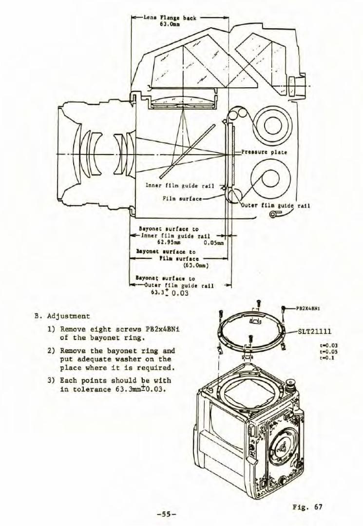
B. Adjustment
Lena Plane• back ---~ 63.0aa
" . '
lnner fl lm ~uide r• i l
1'1111 aurflce
Bayontt turract to Jnner fll11 guide rail
62.9~- o.os .... a&yonet 1urface t o
Hia turhce (6 3. °""')
layone~ eurf ace to utar f lla guide rail
+ 63. 3_ 0.03
1) Remove eight scr ews PB2x4BNi of the bayonet ring .
2) Remove the bayonet ring and put adequate washer on the place where it is r equir ed .
3) Each points should be with in tolerance 63.3mm±0.03.
-55-
uter fll• gu ide rall
~
' r -;
t -0.03 t-0 ,0S t -0 . 1
Fig. 67
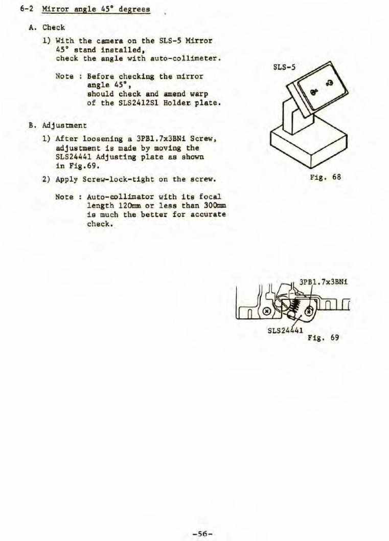
6-2 Mirror angle 45° degreee
A. Check
l ) With the camera on the SLS-5 KiTror 45° stand inetalled , check the angle with auto-collimeter.
Note : Before checking the mirror angle 45°,
B. Adjuetment
ehould check and amend warp of the SLS2412Sl Holde~ ~late.
1) Af ter looeening a 3PB1. 7x3BNi S crew, adju11tment is made by moving the SLS24441 Adjusting pl ate as shown in Fig.69 .
2) Apply Screw- lock-tight on the s crew.
Note : Auto-eollimator with its focal length 120mm or less than 300mm ie much the better for accurate check .
-56-
SLS- 5
Fig. 68
3PB1 . 7x3BNi
Fig. 69
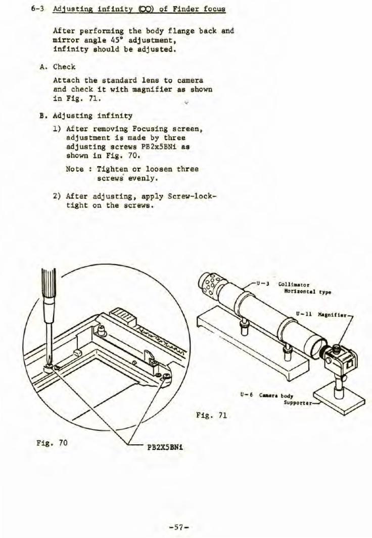
6-3 Adjusting inf inity (X)) of Finder focus
After performing the body f lange back and mirror angle 45° adj us tment , infinity ahoul d be adjusted.
A. Check
Attach the s tandard lens to and check it with magnifier in Fig. 71.
B. Adj usting infinity
camera as shown
l) After removing Focusing screen, adjustment i s made by three adjusting screws PB2x5BNi as shown in Fig . 70 .
Note : Tighten or l oosen thr ee screwâ evenly .
2) After adjusting , apply Screw-locktight on the screws.
Fig. 71
Fig. 70 PB2X5BN1
- 57 -
Colllu to r Norhontal t1p.
u - 6 c- .. bocl1 Su1port1r
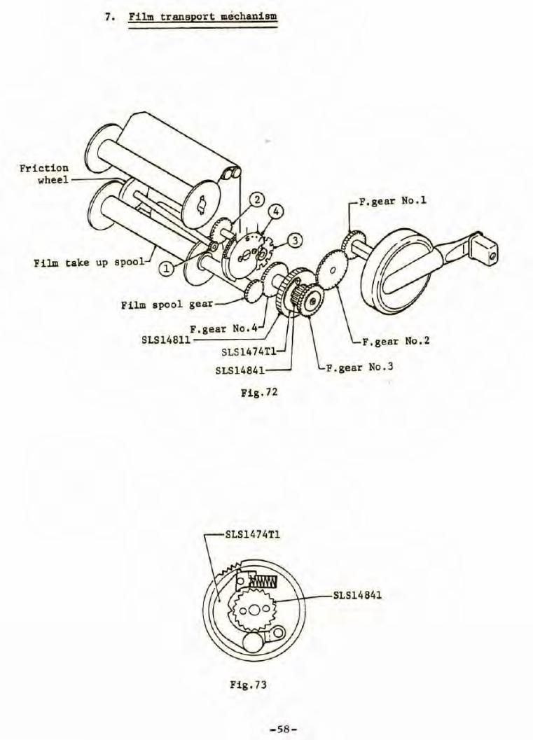
7. Film transport méchanism
Friction wheel ----::;;:;:.;;~
Film take up spool
Film
S F.gear No.4
LS14811...----J SLS1474Tl
SLS14841-~
Fig.72
SLS1474Tl
Fig. 73
- 58-
F.gear No.l
No. 2
F .gear No.3
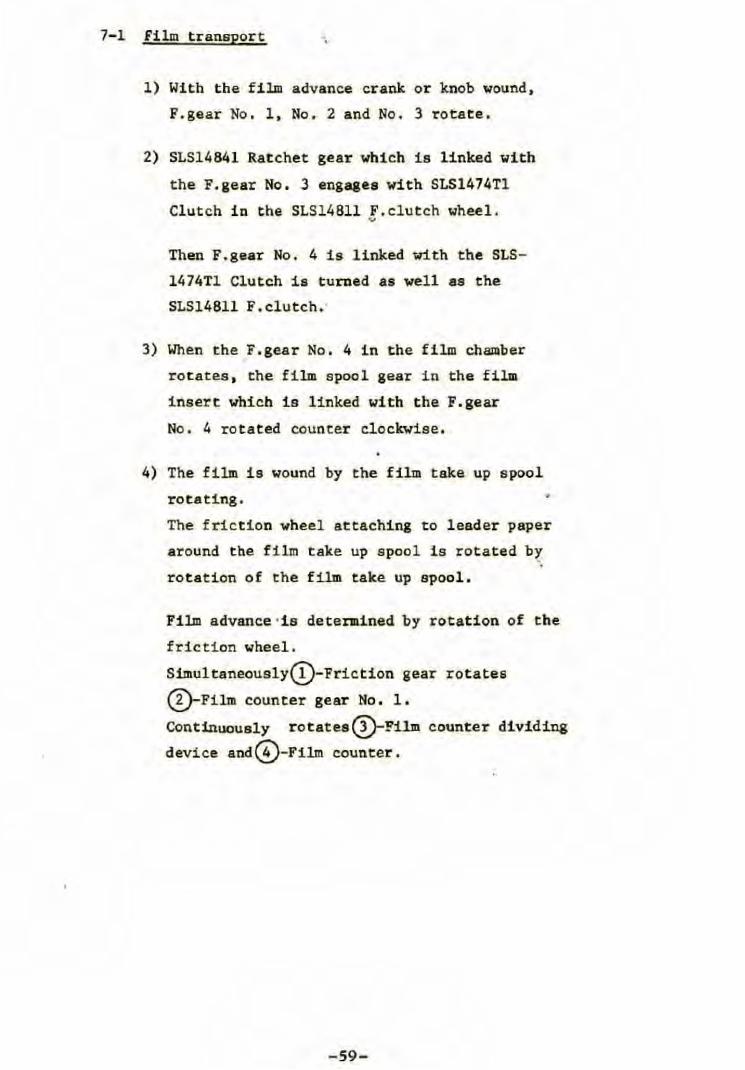
7-1 film transport
l) With the film advance cranlt or knob wound,
F.gear No . l, No. 2 and No. 3 rotate.
2) SLS14841 Ratchet gear wbicb is linked witb
the F.gear No . 3 engagea witb SLS1474Tl
Clutch in the SLS14Bll F.clutcb wheel. V
Tben F.gear No. 4 is linked with the SLS-
1474Tl Clutch is turned as well as the
SLS14811 F. clutcb.·
3) When the F.gear No. 4 in the film chamber
rotates, the film epool gear in the fila
insert which is linked with the F.gear
No. 4 rotated counter clockwise .
4) The film is wound by the film take up spool
rotating.
The fric tion wheel attaching to leader paper
around the film take up spool is rotated b~
rotation of the film take up spool.
Film advance ·is determined by rotation of the
friction wheel.
Simultaneously(!)-Friction gear rotates
~Film counter gear No . l .
Continuously rotatesQ)-Film counter dividing
device and~-Film counter.
-59-
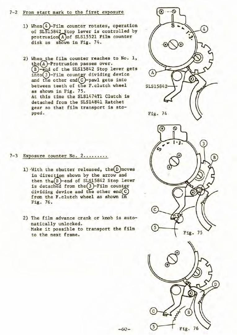
7-2 From start mark to the first exposure
1) When(t;)_Film counter rotates , operation of S~584~top l ever is controlled by protrusion~of SLS15521 Film counter disk as shown in Fig. 74.
2) When the film count er reaches to No. 1 , ~~Protrusion passes over. \!)-e~ of the SLS15842 Stop lever gets into 3 -Film count~ dividing device and t e other end C -pawl gets into between teeth of t e F. clutch wheel as shown in Fig. 75. At this time the SLS1474Tl Clutch is detached from the SLS14841 Ratchet gear so that film transport ia stopped.
7-3 Exposure counter No. 2 ... . .... .
1) ·With the s hutter released, the~oves in direc~n sbown by the arrow and then the~-end of SLW.5842 Stop l ever i s detached from the 3 Film counter dividing device and t e other end~ from the F.clutch wheel as shown in Fig. 76 .
Fig. 74
2) The film advance crank or knob is automatically unlocked . Make it possible t o transport the film 5 r----<L-
to the next frame .
-60-

7-4 After 15 exposures for 120 ,. 30 exposures for 220
1) With 120 Roll- fi l m insert :
When winding the film advance lever more after the fixed number of exposures have been taken (15), turn of t he exposure counter is stopped because the{!)- protrusion on back of SLS15521 Film counter base strikes against the SLS1571T2 Change-over lever as shown in Fig. 77-1 .
2) With 220 Rool -f ilm insert
With 220 Roll -film insert set into body, the SLS1571T2 Change-over lever is pushed up i n direclion shown by the arrow.
Therefore, after the f ixed number of exposures have been taken (30), the(Ê)-protrusion strikes against the SLS156l!'Stopper as shown in Fig: 77-2.
3) In above steps 1) and 2), the SLS1541Tl Dividing device is atopped i n position to prevent moveanent of the SLS15842 Stop lever .
Above means that t he end~of SLS15842 St op lever is on the top of the divid ing device and can not get into its groove as shown in Fig . 77-1 and 77-2 .
4 ) (Î)-Friction gear that conveys rotation cir"the friction wheel engages with~SLS-153151 Film counter gear No. 1 .
As the film is wound further ,(Ï)-Fi lm counter gear N~ l is pushed asiè(e by rotation of the 1 - Friction gear as shown in the Fig . 78 ecause~Film counter is stopped.
Therefore, they are disengaged from each others. Consequently , the film spool gear turn freely to wind film only without advancing t he exposure counter .
-61-
SLS15842 SLS1541Tl
Fig .77-1
SLS1541Tl
Fi g. 77-2
(Pushed aside)
Fig . 78
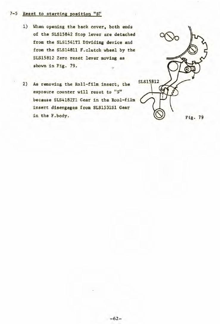
7-5 Reeet to starting position "S!'
1) When opening t he back caver, both ends
of the SLS15842 Stop lever are detached
from the SLS1541Tl Dividing device and
from the SLS14811 F. clutch wheel by the
SLS15812 Zero reset lever moving as
shown in Fig . 79. ...
2) As removing the Roll-film insert, the
exposure counter will reset to "S"
because SLS4182Xl Gear in the Rool-film
insert disengages from SLS1531Sl Gear
in the F.body.
-62-
Fig. 79
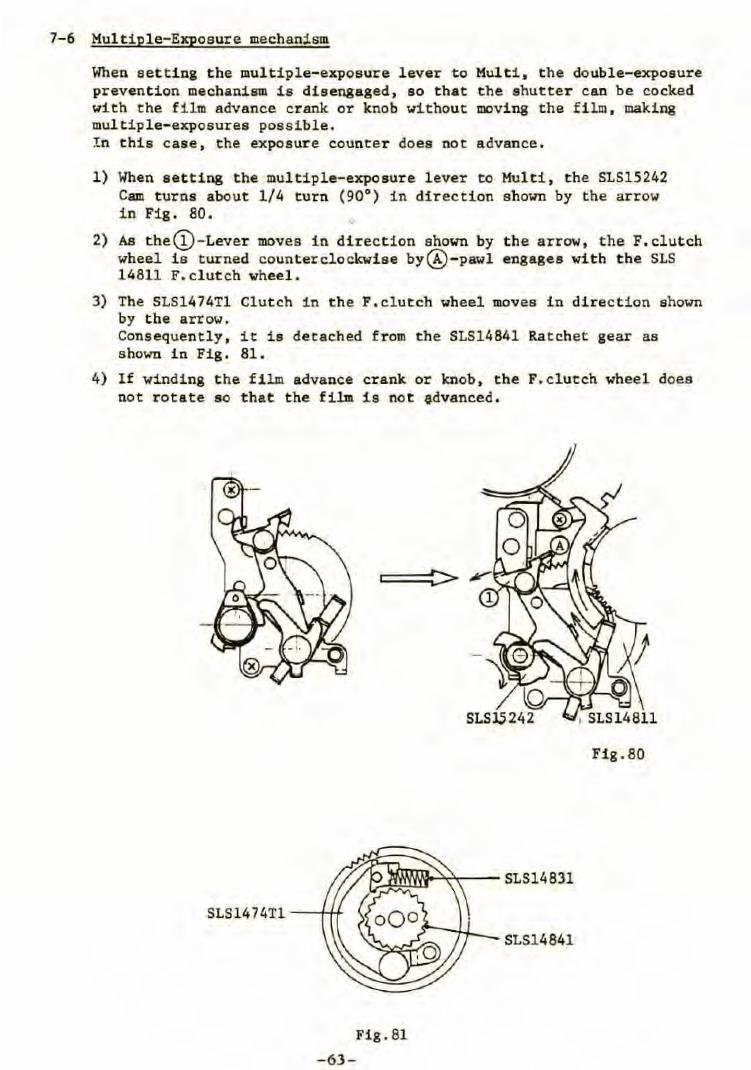
7-6 Multiple-Exposure mechanism
When eet t ing the multiple-expoeure lever to Mult i , t he double-expoeure prevention mechauism is dis engaged , 80 that t he 8hutter can be cocked with the film advance crank or knob without moving the f i lm , making multiple- eXJ>osures possible. !n this case, the exposure counter does not advance .
l) When 8ett1ng the multiple-exposure lever to Cam turne about 1/4 turn (90°) in di rection i n Fig . 80.
2) As the@-Lever moves in direction shown by wheel is turned countercloclcwi s e by@- pawl 14811 F.clutch wheel .
Multi , the SLS15242 shown by the arrow
the ar r ow, the F. clutch engagea with the SLS
3) The SLS1474Tl Clutch in t he F.clutch wheel moves in direction shown by the arrow. Consequently, it is detached from the SLS14841 Rat chet gear as shown in Fig. 81.
4) If winding t he film advance crank or knob, the F. clutch wheel does not rotate 80 that the film is not edvanced.
Fig. 81
-63 -
SLS14841
Fig.80
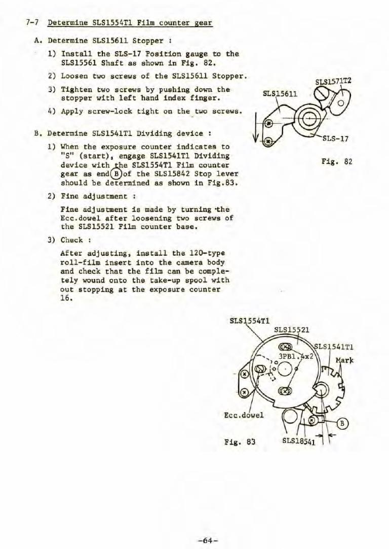
7-7 Determine SLS1554Tl Film counter gear
A. Determine SLS156ll Stopper :
1) Install the SLS-17 Posi tion gauge to t he SLS15561 Shaft as shown in Fig . 82 .
2) Loosen two screws of the SLS15611 Stopper.
3) Tighten two screws by pushing down the stopper with left band index finger.
4) Apply screw-lock tight on the, two screws.
B. Determine SLS1541Tl Dividing device :
1) When the exposure counter indicates to " S" (start) , engage SLS1541Tl Dividing device with~e SLS1554Tl Film counter gear as end\!!}of the SLS15842 Stop lever should be determined as shown in Fig . 83.
2) Fine adjustment
Fine adjustment is made by turning •the Ecc.dowel after loosening two screws of the SLS15521 Film counter base.
3) Check :
After adjusting, install the 120-type roll-film insert into the camera body and check that the film can be completely wound onto the take- up spool with out stopping at the exposure counter 16.
SLS1554Tl
Fig. 83
-64-
SLS1571T2
Fig . 82
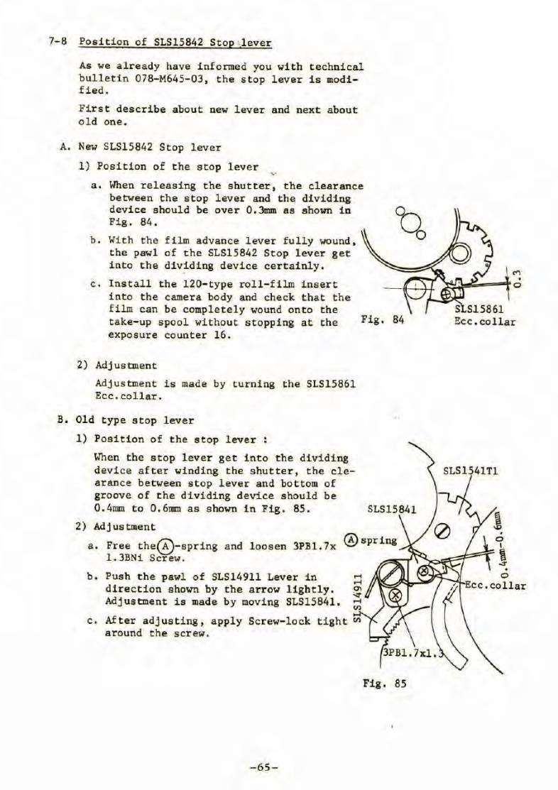
7-8 Position of SLS15842 Stop ',lever
As we already have informed you wi th technical bulletin 078-M645-03, t he stop lever is modified.
First describe about new lever and next about old one .
A. New SLS15842 Stop lever
l) Position of the stop lever ·v
a. When releasing the shutter, the clearance between the stop lever and t he dividi ng device should be over 0 . 3mm as s hown i n Fig . 84.
b . With the film advance lever full y wound , the pawl of the SLS15842 Stop lever get 1nto the div~ding device cer tai nly.
c. Install the 120- type roll- f i lm inser t into the camera body and check t hat the film can be completely wound ont o the take-up spool without stopping at the exposure counter 16.
Fig. 84
2) Adjustment
Adjustment is made by turning the SLS15861 Ecc.collar.
B. Old type stop lever
1) Position of the stop lever :
When the stop lever get into the dividing device after winding the shutter , the clearance between stop lever and bot tom of groove of the dividing device should be 0 . 4mm to 0.6mm as shown i n Fig. 85.
2) Adjustment
a. Free the~-spring and l oosen 3PB1. 7x l.3BN1 Screw.
b . Push the pawl of SLS14911 Lever in direction shown by the arrow lightly . Adjustment 1s made by moving SLS15841.
....;
....;
°' ~ ....; l'J)
c. After adjusting, apply around the screw.
.4 Screw- lock tight l'J)
-65-
Fig . 85
Ecc.collar
SLS1541Tl
3) Position of the ecc . collar
a. Check
1. Install the 120 type roll-film insert into the camera body and check that the f ilm can be completely wound on to the take-up spool without stopping at the expoaure counter 16.
2. Each film advance must be made at a single revolution of the film advance crank or inob.
b. Adjustment :
1. Adjustment ia made by turning the ecc .collar.
2. After adjusting, apply Screv-lock tight on the acrew •
•
-66-
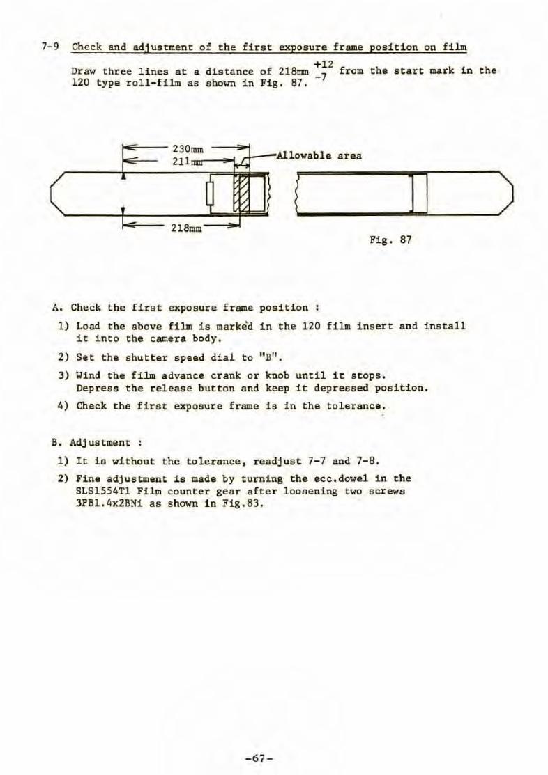
7-9 Check and adjusanent of the first exposure f rame position on film
+12 Dr aw t hree lines at a distance of 218t1111 _7 from the start mark in the 120 type roll-film as shown in Fig. 87.
230mm 211 Allowable area
i ] 1
218mm Fig. 87
A. Check the first exposure frame position :
.1) Load the above film is marke'd in the 120 film insert and install it into the camera body.
2) Set t he shutter speed dial to "B".
3) Wind the film advance crank or knob unti.1 it s tops. Depress the release button and keep it depressed position.
4) Check the first exposure frame i s in the tolerance.
B. Adjustment :
1) It is without the tolerance, readjust 7-7 and 7-8.
2) Fine adjustment is made by turning the ecc.dowel i n the SLS1554Tl Film counter gear after loosening two screws 3PBl.4x2BNi as shown in Fig.83.
- 67-
)
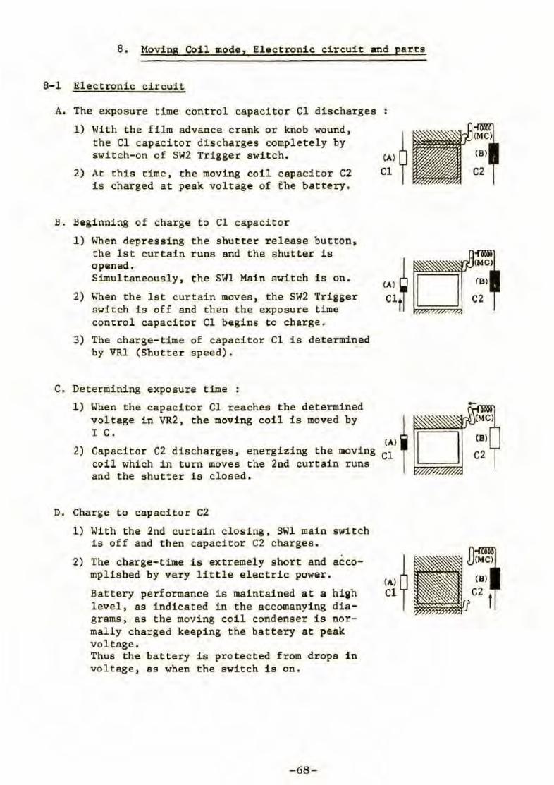
8 . Moving Coil mode, Electronic circuit and parts
8-1 Electronic circuit
A. The exposure time control capacitor Cl discharges
1) With the film advance crank or knob wound, the Cl capacitor discharges completely by switch-on of SW2 Trigger swit ch.
2) At this time , the moving coil capacitor C2 i s charged a t peak voltage of fhe battery.
B. Beginning of charge to Cl capacitor
1) When depressing the shutter r eleas e button, the l st curtain runs and the shutter is opened. Simultaneousl y, the SWl Main sv itch is on .
2) When the lst curtain moves , the SW2 Trigger switch is off and then the exposure t ime con t r ol capacitor Cl begins to charge.
3) The charge- time of capacitor Cl i s determined by VRl (Shutter speed).
C. Determining exposure time :
1 ) When the capacitor Cl reaches the determined voltage in VR2, the moving coil is moved by I C.
2) Capacitor C2 discharges , energizing the movi ng coil which in turn moves the 2nd curtain runs and the shu tter is closed.
D. Charge t o capacitor C2
1) With the 2nd curtain cl osing, SWl main swi t ch is off and t hen capacitor C2 charges.
2) The charge-time is extremely s hort and accomplished by ve ry lit tle elec tric power.
Battery performance is maintained a t a high level , as indica t ed in the accomanying diagrams, as the moving coil cond enser is normally charged keeping the battery at peak voltage. Thus t he battery is protected from drops in voltage, as when t he switch i s on.
-68 -
(A)~ Cl 1
(A ) ~ D Cl~
(A)
Cl
(A)~ Cl y
. . , C2
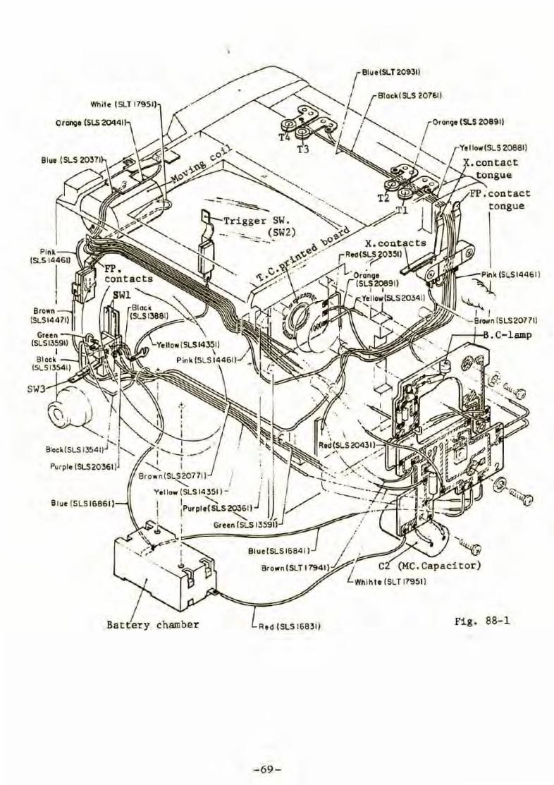
Pink (SLS 1'1461)
~ r 1
~Bt<Mn (SLS20771)
.C-lamp
SW3
Blue ISLSl6861)
BatteTy chambeT Red (SLS 16831) Fig. 88-1
- 69-
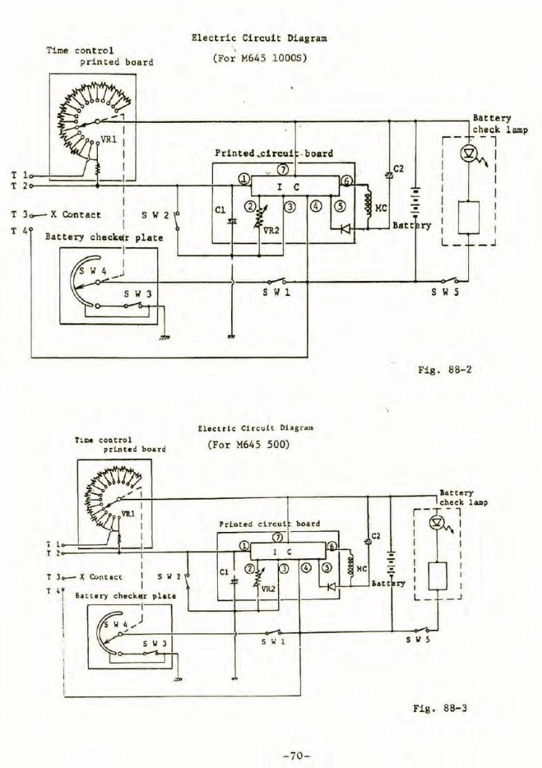
Time contro l printed board
El ectric Circuit Diagram
(For M645 10005)
'--"~_.c,..:;...~~r-~~~~~~~~~~~~"'T':'------~.,--~---~Battery check la111p
T 3o-- X Contact s w 2
T 4 Battery check•r plate
1
Tune coDtrol printe d boa'l'd
T 3- X C.C.otact s Il 2
T 40
Cl 3 ©
C2
• •
MC • 1
VR2 1...-<lt'l-l..."-_J Bat t ry 1
1
L_ ---1-----'
Elcctrlc Circult Di agram
(For M645 500)
© Q) MC
. -
s w s
Fig. 88-2
y:j.1--l.-~ l>at c ry 1
L- _J
Fig. 88- 3
-ïO-
-1 1
1
1
1
_ J
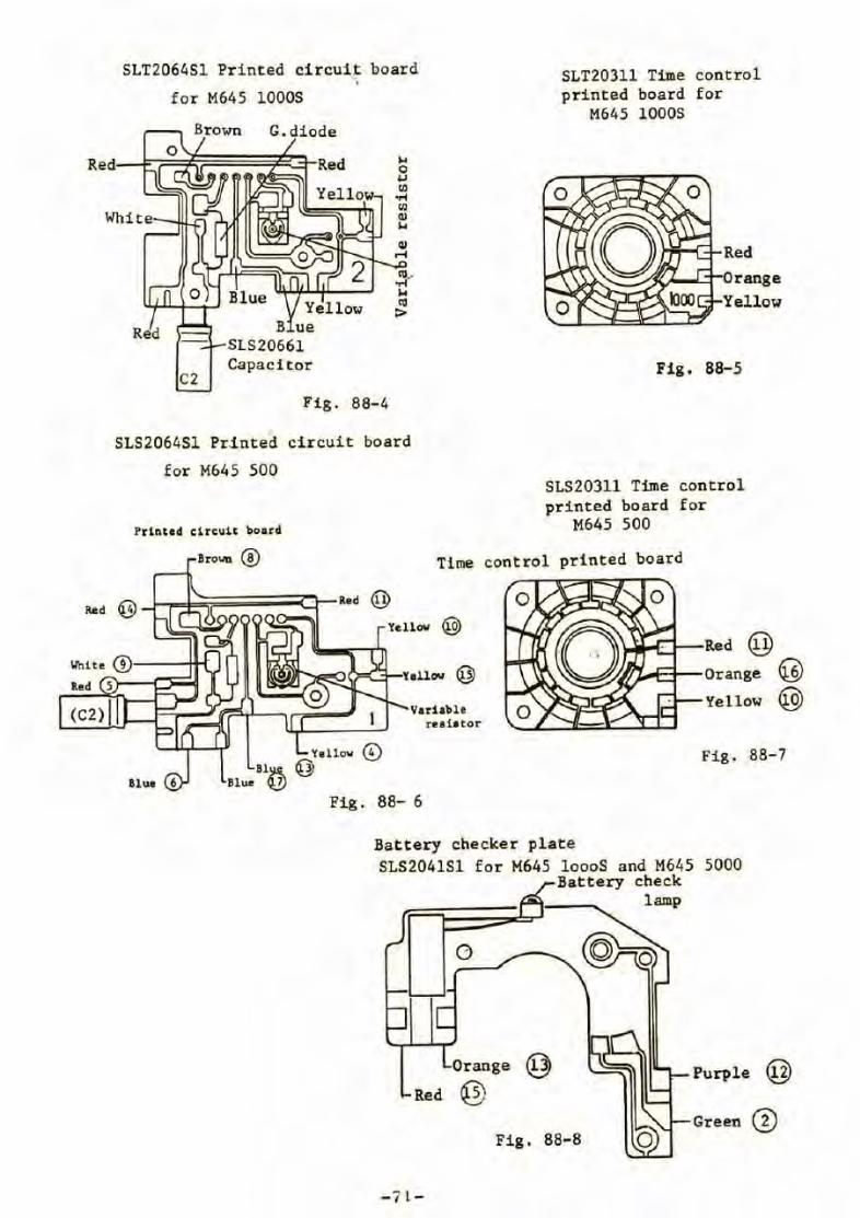
5LT206451 Pr int ed circui~ board . for M645 10005
G.diode
Red~i;~~r.;';';~;t~]Red
Red
C2 Capacitor
Fig. 88-4
515206451 Printed circuit board
for M645 500
Prlnted clrcult board
Brow @
SLT20311 Time control printed board for
M645 10005
Fig. 88- 5
SLS20311 Time control pri n ted board for
M645 500
Time cont rol prin t ed board
Variable
Red @ 1..oA- Orange @
' ·'- Yel low @ .A.....11-1
Yallov © Bl~@
Blue Q]} Fig. 88- 6
rea i a tor
Fig. 88-7
Battery checker plate SLS2041Sl for H645 loooS and M645 5000
Battery check lamp
Purple @ Or ange © Red @
Fig. 88- 8 Green@
- 7 1-
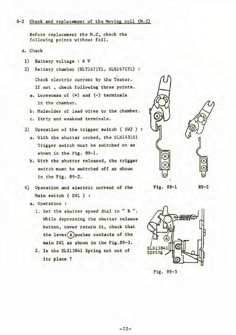
8-2 Check and replacement of the Moving coil (M. C)
Before replacement the M.C, check the following points without fail.
A. Check
1) Battery voltage : 6 V
2) Battery chamber (SLT1671Tl, SLS1671Tl)
Check electric current by the Tester.
If not , check following three points.
a. Looseness of (+) and (-) terminale
in the chamber.
b. Malsolder of lead wires to the chamber.
c. Dirty and weakend terminals.
3) Operation of the trigger switch ( SW2 )
a . With the shutter cocked , the SLS1431Sl
Trigger switch must be switched on as
shown in the Fig. 89-1.
b. With the shutter released, the trigger
switch must be switched off as shown
in the Fig. 89-2.
4) Operation and electric current of the
Main switch ( SWl ) :
a. Operation
1. Set the shutter speed dial to "B ".
While depressing the shutter release
button, never return it, check that
the lever(E)pushes contacts of the
main SWl as shown in the Fig.89-3.
2. Is the SLS13841 Spring not out of
its place 7
-72-
0
Fig. 89-1 89- 2
Fig. 89-3
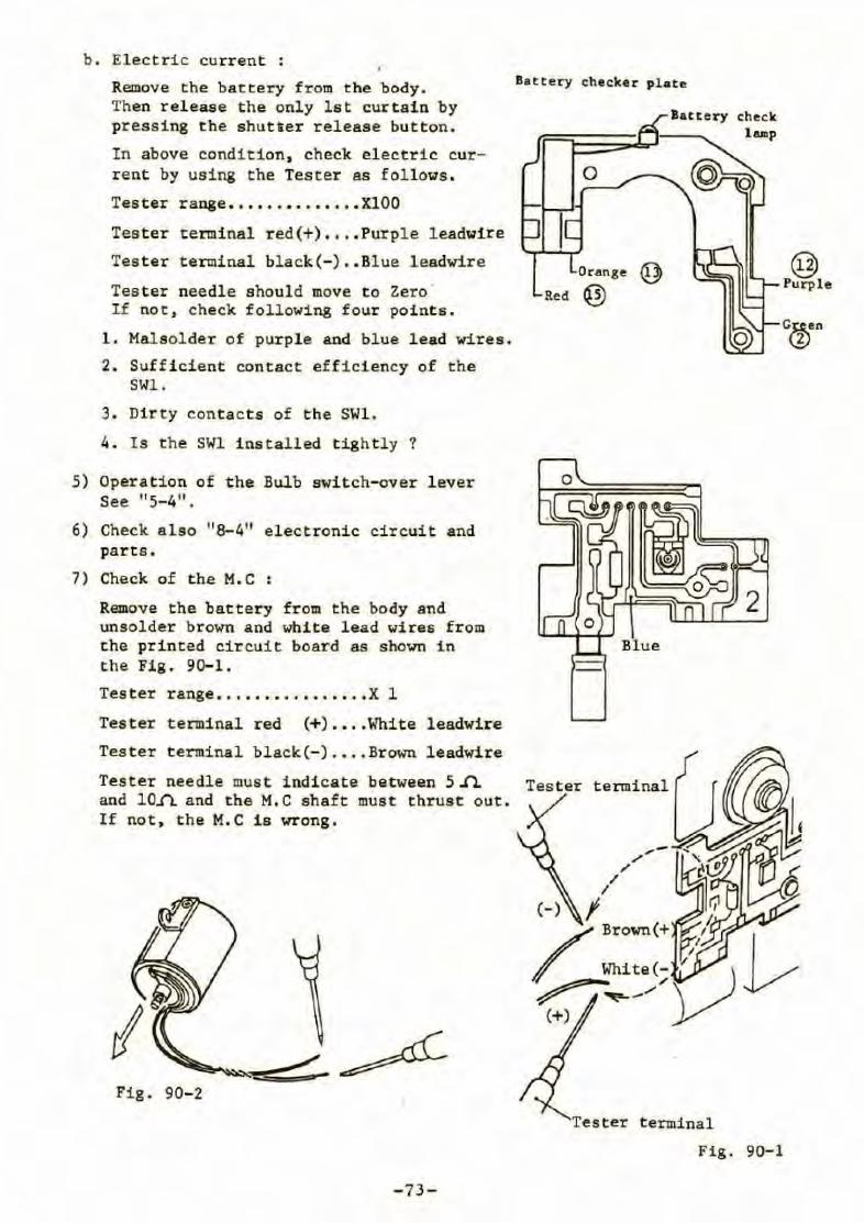
b. Electric current :
Remove the battery from the body. Then release the only lst curtain by pressing the shutaer release button .
In above condition , check electric current by using the Tester as follows .
Tester range •••• •• • •••••• • XlOO
Tester teI1I1inal red(+) • • • • Purple leadwire
Tester terminal black(-) •• Blue leadwire
Tes ter needle should move to Zero · If not, check following four poincs.
1. Malsolder of purple and blue lead wires .
2. Sufficient contact efficiency of the SWl.
3. Dirty contacts of the SWl.
4. Is the SWl installed tightly ?
5) Operation of the Bulb switch- over l ever See "5-4".
6) Check also "8-4" electronic circuit and parts .
7) Check of the M.C
Remove the battery from the body and unsolder brown and white lead wires from the printed circuit board as shown in the Fig. 90-1.
Tes t er range ............... . X l
Tester terminal red (+) • •.. White leadwire
Tester terminal black(-) .••• Br own leadwire
Battery checker plate
lattery check t ... p
0
Orange @ Red @
Tester needl e must indicate between 5 ..n. Tester terminal and 10.fL and the M.C shaft must thrust out. If not , the M. C is wrong.
Fig. 90- 2
- 73 -
terminal
Fig. 90-1
@ Purple
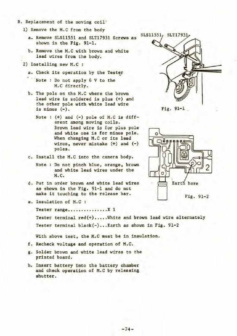
B. Replacement of the moving coil '
1) Remove the M.C from the body
a. Remove SLS11551 and SLT17931 Screws as shown in the Fig . 91- 1.
b . Remove the M.C with brown and white lead wires from the body .
2) lnstalling new M. C :
a. Check its operation by the Tester .,,
Note : Do not appl y 6 V t o the M. C directly.
b. The pole on the M. C where the br own lead wire i s soldered is plus (+) and the o ther pole with white lead wire i s minus (- ) .
Note : (+ ) and (- ) pole of M.C is differ ent among moving coils. Brown lead wire i s for plus pole and white one is for minus pole . When changing M.C or its lead wires . never mistake (+) and (-) poles.
c . lnstall the M. C into the camera body.
Not e : Do not pinch blue, orange , brown and white lead wires under the M. C.
d. Put in order brown and white lead wires as shown in the Fig . 91-1 and do not make it touching t o th e r elease bar.
e. lnsulation of M.C :
Tes ter range . ......... . . .. . X 1
Fig. 91-1 .
Eart here
Fig. 91- 2
Tester t erminal red(+) • .••. White and brown lead wire alternately
Tester terminal bl a ck (-) . • . Ear th as shown in Fig. 91- 2
With above tes t , t he M.C must be in insulation.
f. Recheck voltage and operation of M.C.
g. Sol der brown and white lead wires to the printed board.
h. lnsert battery i nt o the battery chamber and check operation of M.C by releasing shutter.
- 74 -
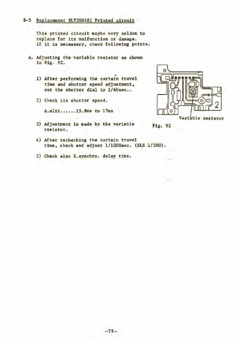
8-3 Replacement SLT2064Sl Printed circuit •
This printed circuit maybe very s eldom to r eplace for its malfunction or damage, If it is necessary , check following points.
A. Adj us t i ng the variable resistor as shown in Fig. 92 .
.... l) After performing the curtai n travel
time and shutter speed adjustment, set the shutter dial to l /60sec ••
2) Check i ts shutter speed.
A.slit . •••.• 15.Sms to 17ms
3) Adjustment is made by the variable resis tor.
4) After rechecking the curtain travel
Fig, 92
time, check and adjust l/lOOOsec . (SLS .l/500).
5) Check also X.synchro . delay t ime.
-75-
Va r iable resistor
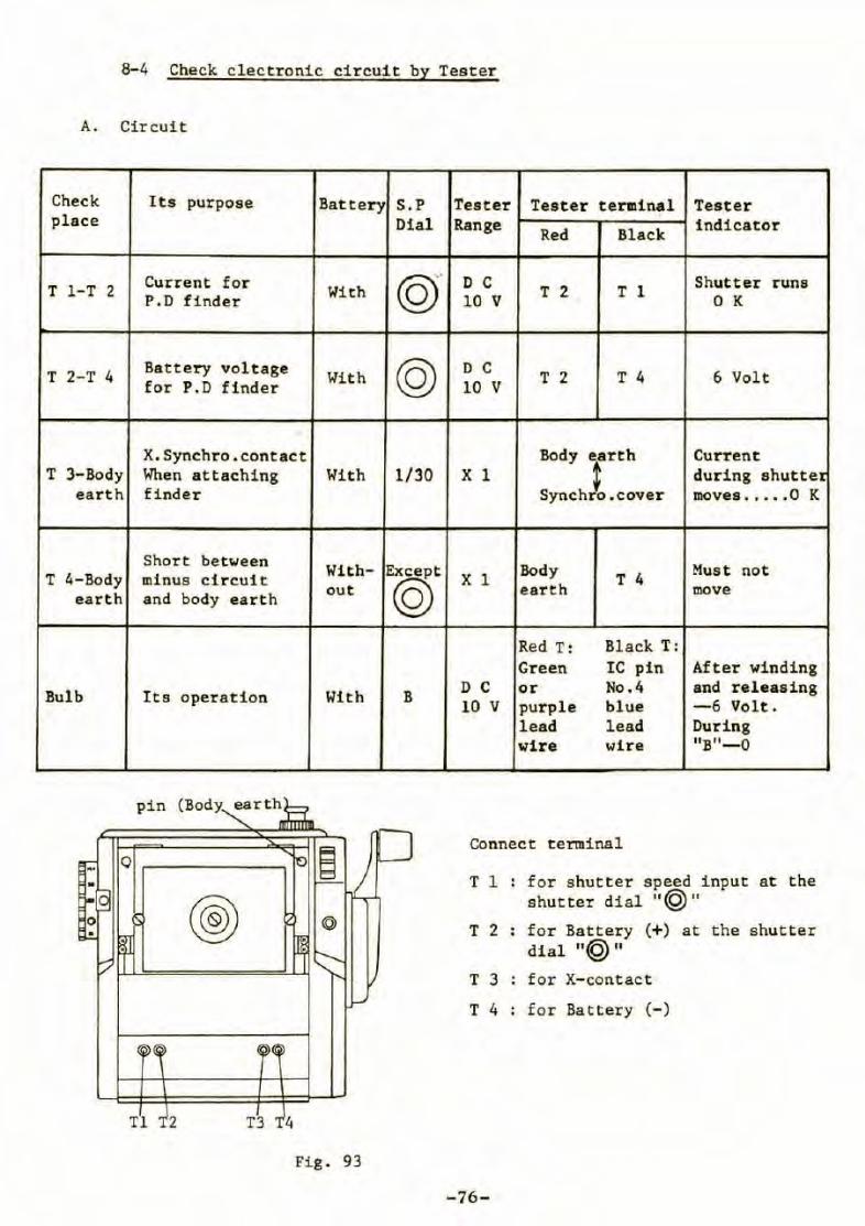
8-4 Check clectronic circuit by Tester
A. Circuit
Check Its purpose Battery S.P Tes ter Teste r termina l Tester place Dial Range
Red Black indicator
T 1-T 2 Current for With © D C T 2 T 1 Shutter runs P.D finder 10 V 0 K
T 2-T 4 Battery voltage With @ D C T 2 T 4 6 Volt for P.D finde r 10 V
'
X.Synchro . contact
:::h):~::ver Current
T 3- Body When attaching With 1/30 X l during shuttet earth finder moves .• .•. 0 K
Short between With- Except Body Mus t not T 4-Body minus circuit X l T 4
eart h and body ea rth out © earth move
Red T: Bl~ck T: Gr een IC pin After winding
Bul b Its oper ation With B D C or No . 4 and r e leasing 10 V purple blue -6 Volt .
lead le ad Du ring wire wi re "B"- 0
COnnect terminal Q
T l for shutter speed input at the
® shutter dial "@" T 2 for Battery (+) at the shutter
di al "@ " T 3 for X- contact
T 4 for Battery (- )
Tl 2 T3 4
Fi g. 93
-76-
1)
2)
3)
4)
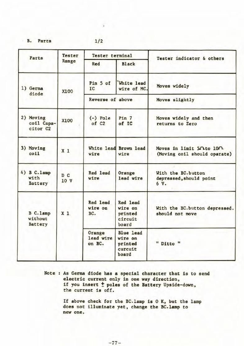
B. Parts 1/2
Partfl Tester Tes ter terminal Tester indicator & others Range Red Black
Pin 5 of ' White lead Moves widely Germa XlOO
IC wire of MC. diode
Reverse of above Hoves slightly
Hoving XlOO
(-) Pol e Pin 7 Hoves widely and then coil Capa- of C2 of IC returns to Zero citor C2
Moving X 1 White lea~ Brown lead Moves in limit SJLto l~ coil wire wire (Hoving coil should oparate)
B C.lamp D C Red lead Orange With the BC.button
with 10 V wire lead wire depressed,should point Battery 6 v.
Red lead Red lead wire on wire on With the BC.button depressed.
B C.lamp X l BC. printed should not move without circuit Battery board
Orange Blue lead lead wire wire on on BC. printed " Ditto "
curcuit board
Note As Germa diode has a special character that is to send electric current only in one way direction, if you insert ! poles of the Battery Upside-down, the current is off.
If above check for the BC.lamp is 0 K, but the lamp does not illuminate yet, change the BC.lamp to new one .
- 77-
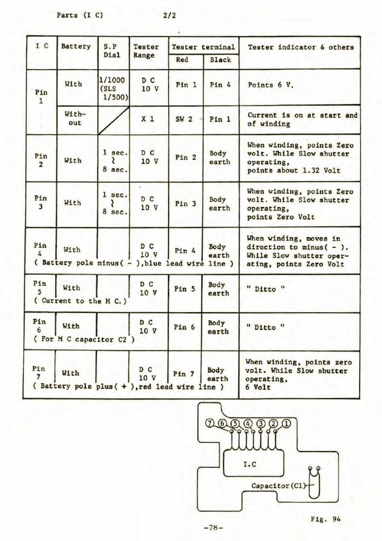
Parts ( l C) 2/2
I C Battery S.P Tester Tester terminal Di al Range Red Black
With 1/1000 D C Pin 1 Pin 4 Pin (SLS 10 V
1 1/500)
With- 1/ X 1 sw 2 Pin 1 . out
Pi n 1 sec . D C Pin 2 Body 2
With ~ 10 V earth 8 sec .
. 1 sec . Pi n With ? D C
Pin 3 Body 3 10 V ear th 8 sec.
Pin Wi t h D C Pi n 4
Body 4 10 V earth
( Battery pole minus( - ) ,blue lead w1.re line )
Pin With D C
Pin 5 Body
5 10 V earth ( Current t o the M C.)
Pin With D C Pin 6 Body 6 10 V earth
( For M C capacitor C2 )
Pin With D C Pin 7 Body
7 10 V earth ( Battery pole plus ( + ) , r ed lead vire line )
-78-
Tester i ndicator & others
Points 6 V.
Current i s on at start and of winding
When winding, points Zero volt. While Slow shut ter operating, points about 1. 32 Volt
When winding, points Zero volt . While Slow shutter operating, points Zero Volt
When winding, moves in direction to minus( - ). While Slow s hutter oper-ating, points Zero Vol t
" Ditto "
" Ditto "
When winding , point s zero volt. W'hile Slow shutter operat ing, 6 Volt
I. C
Capa<itor (Cl~ Fig. 94
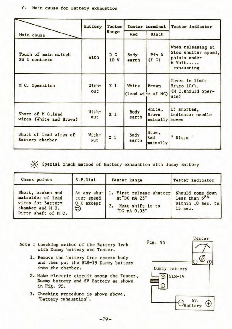
C. Main cause for Battery exhaustion
~ Battery Tester Tester terminal Tester indicator Range
Red Black
'When releasing at Touch of main switch D C Body Pin 4 Slow shutter speed,
SW 1 contacts With 10 V ear th (I C) points under 6 Volt .•••• exhausting
Moves in limit M C. Operation With- X 1. White Brown 5.1'\. t 0 l o.n..
out (lead wire of MC) (M C .should oper -ate)
With- Body White, If s horted, Short of M C ,lead X 1 Brown indicator needle wires (White and Brown) out earth mutually 1110ves
Shor t of lead wires of With- Body Blue, X l Red " Ditto " Battery chamber out earth mutually
~ Special check method of Battery exhaustion with d1J1111Dy Battery
Check points S.P.Oial Tester Range Tester 1ndicator
Short, broken and At any shu- 1. First r e l ease shutter Should come down malsolder of lead tter speed at "oc mA 25" less than ~A wires for Battery 0 K except
2 . Next shift it within 10 sec. to chamber and M C. @ to 15 sec . "oc mA o.os" Dirty shaft of Mc.
Note : Checking method of the Battery leak with Dummy battery and Tester .
Fig. 95
l. Remove the battery from camera body and then put the SLS- 19 Oummy battery into the chamber.
2 . Make electric circuit among the Tester, OWllllly battery and 6V Battery as shown in Fig. 95.
3. Checking procedure is shown above, "Battery exhaustion" .
-79-
Dummy battery
SLS-19
6V. attery +

Special T ool List and Special Measuring Instruments
for Mamiya M645
- 81 -
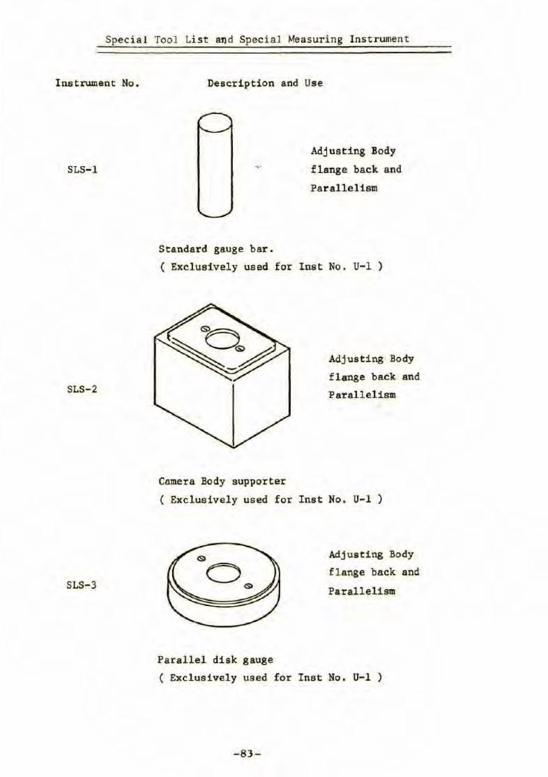
Special Tool List and Special Measuring Inst rument
Instrument No.
SLS-1
SLS-2
SLS-3
Description and Use
Standard gauge bar.
Adjusting Body
flange back and
Paralleliam
( E.xcluaively uaed for Inst No. U- 1 )
Camera Body supporter
Adjusting Body
f lange back and
Paral l elism
( Exclusively used for Inst No . U-1 )
Parallel disk gauge
Adjusting Body
flange back and
Parallelism
( Excluaively used for Inst No. U-1 )
-83-
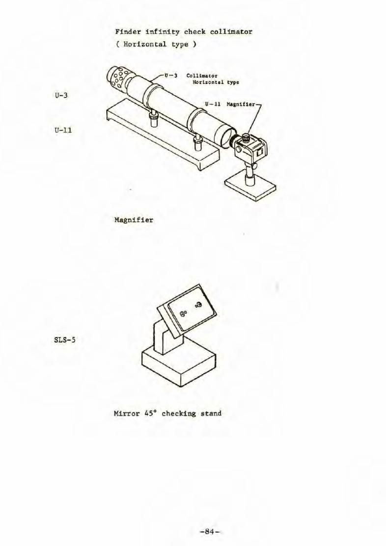
U-3
U-11
SLS-5
Finder infinity check collimator
( Horizontal type )
Magnifier
Collh1ator Horlzontd type
Mirror 45° checki ng stand
-84-
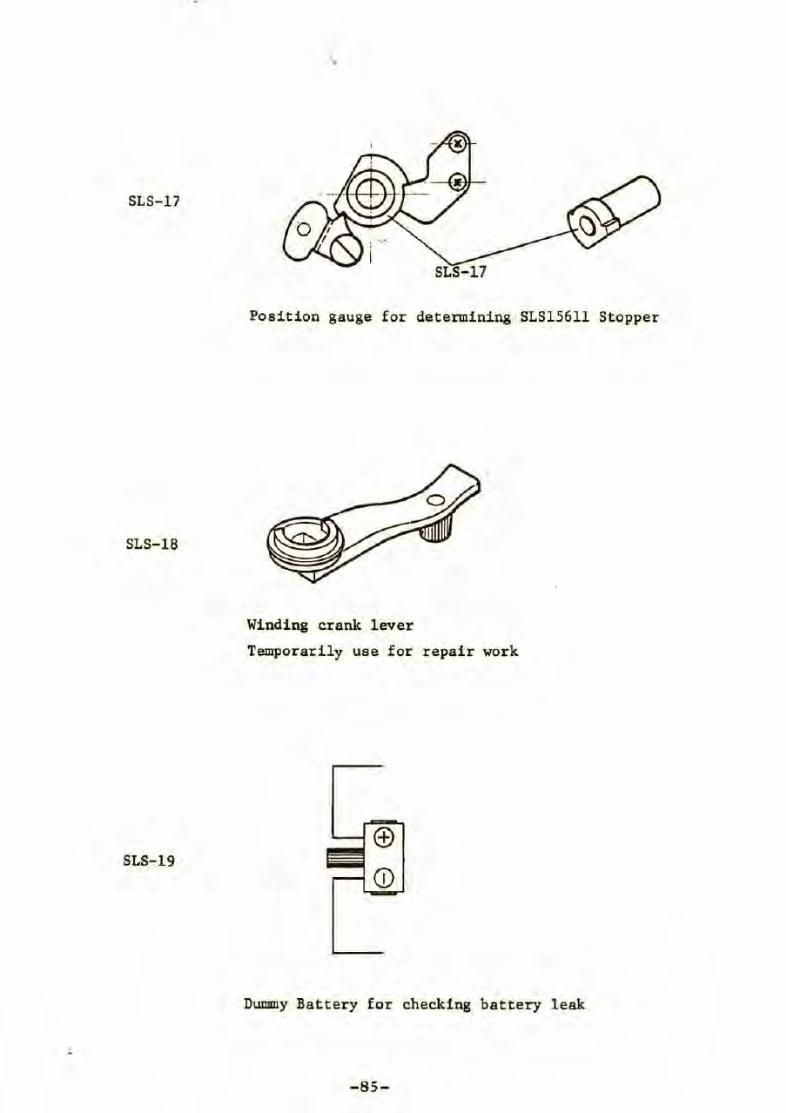
SLS-17
SLS-17
Position gauge for determining SLS15611 Stopper
SLS-18
Winding crank lever
Temporarily use for repair work
SLS-19
DU!lllly Bat tery for checking battery leak
-85-