SERVICE- INSTRUCTION AES II- Absorption...
20
SERVICE- INSTRUCTION Publications-No.: 599 47 22-58/4 replaces 599 47 11-18/1 T.D. 07/2002 English AES II- Absorption Refrigerators (only for built- in in motor caravans) COOLING 3110 RM 4185 RM 4215 RM 4235 RM 4265 RM 4275 RM 4285 RM 4365 RM 4405 RM 4505 RM 4605 RM 4705 RM 4805 RM 5215 RM 5275 RM 5405 RM 6275 RM 6295 RM 6365 RM 6405
Transcript of SERVICE- INSTRUCTION AES II- Absorption...

SERVICE- INSTRUCTION
Publications-No.:599 47 22-58/4replaces 599 47 11-18/1 T.D. 07/2002
English
AES II- Absorption Refrigerators(only for built- in in motor caravans)
COOLING3110
RM 4185RM 4215RM 4235RM 4265RM 4275RM 4285RM 4365RM 4405RM 4505RM 4605RM 4705RM 4805RM 5215RM 5275RM 5405RM 6275RM 6295RM 6365RM 6405
Table of Contents Page1.0 Model Description 3
2.0 AES II System Function 32.1 Priorities 32.2 Switchover Times / Time Delays 32.3 Low Voltage Operation 42.4 Tank Stop 42.5 Thermostat Sensor 4
3.0 Technical Descriptions 53.1 Block Diagram 53.2 Power Module Connections 63.3 Display Module 73.4 Power Module 83.5 Ignition Device 83.6 Thermocurrent Adapter 8
4.0 Installation 85.0 Troubleshooting 85.1 Diagnostics Mode 85.2 Error Analysis and Elimination 9
6.0 Wiring Diagram 117.0 Spare Parts Numbers 128.0 Service Bulletins 139.0 Operation of AESII with solar 17
charging regulators
2

1.0 Model Description
2.0 AES II System FunctionAn AES II refrigerator independently selects between the possible energy sources of 230 V, 12 V, and gas. The control electronics automatically ensure that the refrigerator is supplied fromthe energy source optimal at a given time. You can not operate the refrigerator with morethan one energy source simultaneously. You may also not manually select a certain energysource. The electronic thermostat controls the refrigerator during "ON/OFF" operation, independ-ently of the energy source.
The basic function for the AES II is: cooling under all conditions. The amount of voltageapplied each time is therefore monitored during electrical operation (230 V or 12 V). If the volta-ge falls below the relevant limit values (200 V for mains power supply voltage and 11 V for batteryoperation), gas operation is selected (see low voltage operation). For its operation, the AES IIrefrigerator requires a 12 V continuous plus supply to operate the control electronics.
Operation on a 24-V power supply is not possible.
2.1 Priorities The refrigerators selects the type of energy according to the following priorities:
1) 230V: if the voltage > 200 V
2) 12V: if the motor is running (D+ signal from the generator) and voltage > 11V
3) Gas: if 230V is not present or < 200V, or 12V voltage < 11 V
2.2. Switchover Times / Time DelaysThe following diagram displays the switchover times between the individual energy sources:
3
Refrigerator Mobil
TropicanaSuper-Iso
with AES(Automatic Energy Selector)
withInterior Light with double
Door Look
230V
Gas 12V
immediately
immediately
immediately
15 min. (compare tank stop)
approx 20sec.
I.E.
approx 20sec.
2.3 Low Voltage OperationThe so-called "low voltage gas operation" is an exception. If the electrical power supply voltagein 230-V or 12-V operation is insufficient to maintain the cooling operation, the AES switches togas operation under certain conditions. A yellow LED displays this state. The conditions for swit-ching over to gas operation are described in Section 2.2. If gas operation is selected due to lowvoltage, the refrigerator remains in gas operation for 30 minutes to avoid a continuous switchingback and forth (oscillation) between the energy sources. After 30 minutes of gas operation, theelectronics checks the applied voltage at regular intervals. If the power supply voltage againbecomes sufficient, the refrigerator again switches to 230-V or 12-V operation.
2.4 Tank Stop The AES electronics does not begin operating the refrigerator on gas until the motor has beenturned off for 15 minutes to avoid an undesired switchover to gas operation during a tanking procedure.
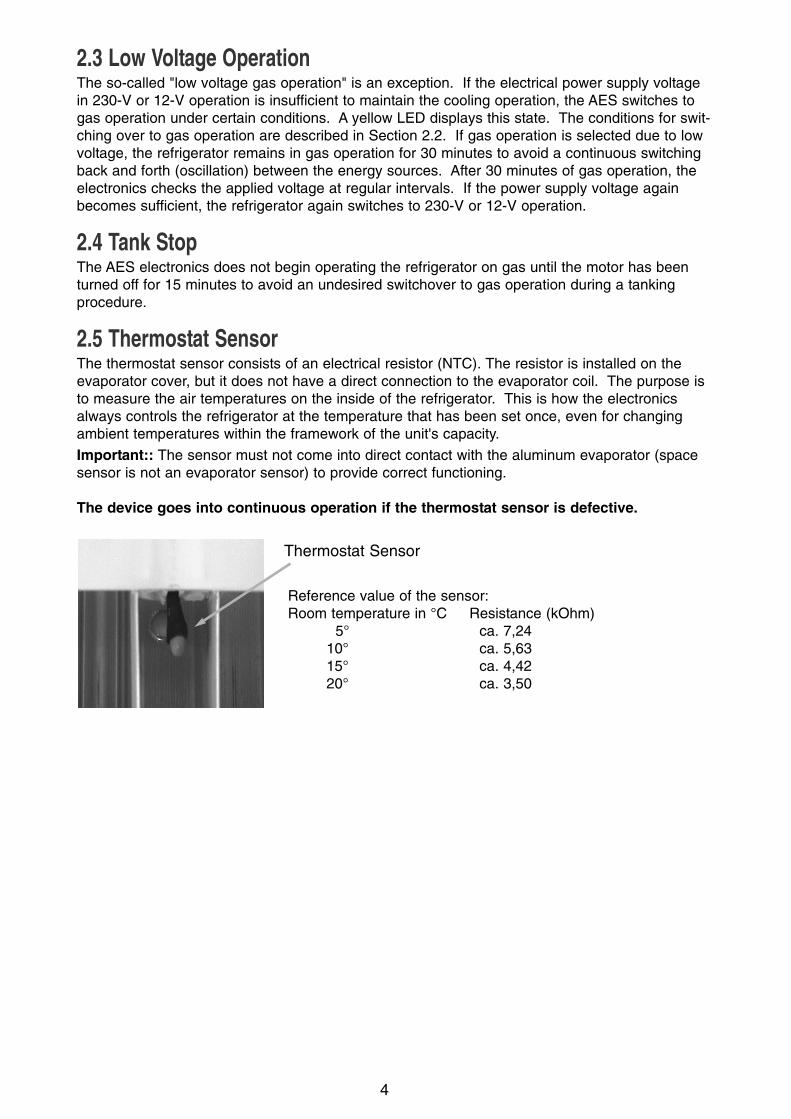
2.5 Thermostat Sensor The thermostat sensor consists of an electrical resistor (NTC). The resistor is installed on the evaporator cover, but it does not have a direct connection to the evaporator coil. The purpose isto measure the air temperatures on the inside of the refrigerator. This is how the electronicsalways controls the refrigerator at the temperature that has been set once, even for changingambient temperatures within the framework of the unit's capacity.
Important:: The sensor must not come into direct contact with the aluminum evaporator (spacesensor is not an evaporator sensor) to provide correct functioning.
The device goes into continuous operation if the thermostat sensor is defective.
4
Thermostat Sensor
Reference value of the sensor:Room temperature in °C Resistance (kOhm)
5° ca. 7,2410° ca. 5,6315° ca. 4,4220° ca. 3,50
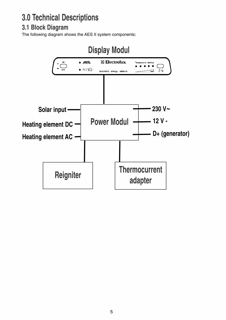
3.0 Technical Descriptions3.1 Block DiagramThe following diagram shows the AES II system components:
5
Display Modul
Power ModulSolar input 230 V~
12 V -
D+ (generator)
ReigniterThermocurrent
adapter
Heating element DC
Heating element AC

3.2 Power Module Connections
6
Connection Type Definition
P1 I/ O Connection cable display/ power module
P2 I Temperature sensor
P3 I/ O Reigniter
P4 O Lifting magnet
T1 O 12V DC lighting
T2 O 12V DC heating element
T3 I 12V DC power supply (+)
T4 I 230V AC
T5 O 230V AC heating element
T6 O 230V AC heating element
T7 I 230V AC
T8 I Ground
T9 I Generator (D+)
T10 I Solar system

3.3 Display ModuleThe display module is located on the control frontplate of the AES II refrigerator.
You must operate the power switch (A) to turn the device on.
The AES function LED (B) then lights up green, and the middle LED (E) lights up yellow to displaythe selected temperature setting.
You can use the momentary-contact pushbutton for temperature selection (D) to change the refri-gerator section temperature setting. The low voltage LED (C) lights up yellow if the refrigeratorhas selected gas operation to maintain the refrigerating capacity due to low voltage in an electri-cal supply source (230 V or 12 V).
If there is a fault during gas operation (gas couldn't be lit, gas container empty, etc.), the AESLED (B) flashes red. In this case, the device does not continue to cool. You must eliminate thegas fault and start the refrigerator again. (Use the power switch to switch the refrigerator off andon again.)
Important:: If there is a fault during gas operation and you don't notice it before the refrigeratorchanges to 230 V, for example, due to a priority change, the AES LED (B) again changes togreen until the cooling function has been established again. However, the next time it wants tochange to gas operation, the fault is displayed again, and gas operation is not started. The rea-son is that there are legal regulations that do not permit the device to carry out an automaticreset. If you have a gas fault displayed by a red flashing AES LED (B), you absolutely mustacknowledge this gas fault by using the power switch to switch the device off and on again.
7
A B
C
D
E
A Power switchB AES operation indicator GREEN: Refrigerator working
flashing RED Fault in the gas operation,refrigerator not cooling.
C Low voltage LED YELLOW Rrefrigerator in gas opertion,because the electrical power supplyvoltage is insufficient.
D Sensor for temperature settingE LEDs for displaying the selected temperature setting

3.4 Power Module The power module (A) is located on the backside ofthe refrigerator. A multicore cable connects thepower module and the display module.
There are fuses to protect both electrical heatingcartridges located in the power module. All theelectrical components for controlling the various ope-rating modes are located in this module. The module's printed circuit board has been sealed completely water tight to protect against environmental influences.
3.5 ReigniterThe reigniter is also located on the backside of the refrigerator. The power module supplies thereigniter3 with voltage. Refer to Publication Bulletin Number 599 4716-54/5 (Pages 13-14) fordetailed information about the ignition devices used.
3.6 Thermocurrent Adapter The thermocurrent adapter is located between the igni-tion fuse and the thermoelement coupling. The powermodule controls the thermocurrent adapter. The adap-ter serves to switch off gas operation during the chan-ge from gas to another operating mode by interruptingthe thermocurrent to the ignition fuse.
4.0 Installation To guarantee the orderly functioning of the AES II refrigerator, correct electricalinstallation is absolutely necessary.
The 12-V connection to the battery must be a 2-pole connection.
The connection cable must be 6 mm2 and be 10 mm2 for greater lengths.
The D+ control input must be wired from the generator to the 12-V supply termi-
nal (cable cross-section 1 or 1.5 mm2, otherwise 12-V operation is not possible).
5.0 Troubleshooting5.1 Diagnostics Mode The AES II system has a built- in diagnostics program used to test basic system functions.
The test program offers the capability to switch the refrigerator deliberately into certain operatingstates.
The following test sequences are available:
- Self-test for the display module and power module and for communication between bothcomponents
- AC operation (230 V) test
- DC operation (12 V) test
- Ignition device test
8
A

a) PreparationsThe AES II device must be connected to a 230-V supply line and a 12-V supply. You must con-nect a gas cylinder and open the gas supply to test the gas function.
b) Test execution You must proceed as follows to arrive at diagnostics operation:
1. Switch off the device
2. Press the button for the temperature setting and keep this button depressed. Use the power switch to switch the device on.
3. Keep the button for the temperature setting depressed until the AES operation LED switches tored and diagnostics operation begins.
The AES operation LED is red during diagnostics operation.
A self-test for both electronic modules is first carried out, and all the display module LEDs arecontrolled once. The left temperature LED then lights up. Diagnostics operation has selected theoriginal position.
You can select the following tests when you activate the temperature selection switch:
LED 1: All outputs are switched off, standby mode
LED 2: Mains power supply, 230-V heating cartridge is controlled
LED 3: Lifting magnet, thermocurrent adapter, and the ignition device* are controlled
LED 4: 12-V operation, 12-V heating cartridge is controlled
LED 5: Ignition device is controlled
* Important: For safety reasons, it is possible to control the lifting magnet just once. If the liftingmagnet is controlled again, you must first switch the device off and then start diagnostics operation again.
C) Terminating diagnostics operationYou can use the power switch at any time to switch the device off and terminate diagnostics ope-ration. If someone unintentionally forgets to switch off the diagnostics operation, the device swit-ches back to cooling operation after four minutes.
5.2 Error Analysis and Elimination
Errors according to priority:
Cause 1: The lifting magnet does not remain tightened for the required 20 seconds.The thermoelectric voltage is insufficient, and the ignition fuse closes.
Elimination 1: Exchange the electronic.
Cause 2: The spark plug fires even though there is a flame present (no flame recognition). The electronics switch to fault after 25 seconds.a) The connection between the spark plug and ignition cable is deficient. (Refer
to Bulletin 599 4717-69/1, Page 15.)b) The ignition device is defective. (See Bulletin 599 4716-54/5, Pages 13-14.)
Eliminaion 2: Chance the spark plug or the reigniter.
9
1. Gas Operation
Error: Fault LED flashes red

Cause 3: After the lifting magnet drops, the AES again tries to ignite and then goes to a fault after 25 seconds. Is the thermoelement on the thermocurrent adapter loose?
Elimination 3: Hand-tighten the screw connection (SW 8mm).
Cause 4: The thermoelectric voltage is not sufficient to keep the ignition fuse open. The reason is due to wear and tear and component tolerances, for example:
1. Bad thermoelement (soot formation)
2. The thermocurrent adapter's internal resistance is too high.
3. The holding current for the magnetic insert for the ignition fuse is too much.
Elimination 4: Exchange the thermocurrent adapter and the ignition fuse and/or thermoelement. (See Bulletin 599 4721-91/7, Page 16.)
Cause 5: The lifting magnet does not press the ignition fuse down deeply enough, so there is no mechanical contact in the magnetic insert
Elimination 5: To check after tightening the lifting magnet, press down on the red ignition fuse button. If the flame stops after the lifting magnet drops, the lifting magnet or the ignition fuse must be adjusted.
In the factory setting, the AESII electronics control the lighting. If there is a lighting defect, firstcheck the light. If the lighting does not function even if the light is intact, you must proceed as fol-lows:
1. Disconnect and insulate the whiteand yellow cable on the connec -ting terminal (A).
2. Connect the B and C connectionsof the connecting terminal togetherto test them.
If the lighting functions, use a 15-Ohm resistor with spare part number 295 1749-10/6 inthe connecting terminal as a connection.
10
2. Interior Light
A
B C
black black
brown white
12V-connectionTerminal block
bla
ck
wh
ite
wh
ite
red
wh
ite
Ground Ground
yello
w
AES II ELECTRONIC

6.0 Wiring Diagram
11

12
7.0 Spare Parts Numbers for the Functional PartsThermocurent adapter 295 1956-20/6
Ignition fuse 295 1157-10/2
Hexagon nut 280 1043-02/3
AESII-electronic 295 1876-10/7
3 amp AC fuse 294 3541-00/9
20 amp DC fuse 210 6389-10/5
Lifting magnet 295 1151-00/6
Temperature sensor cpl. 295 2072-00/3wih cable
Old version of the reigniter (Fa. Cramer)295 1654-10/8
New version of the reigniter (Anstoss Company)295 2368-00/5
Bulletin 599 4716-54/5, Note page 13 and 14

13
8.0 Bulletins

14

15

16
Publication-No.: 599 4721-91/7 / Service 99.02.03 B.O./K.V.

9.0 Operation of AES II with solar charging regulatorsOperation of Dometic refrigerators with AES II control and solar charging regulators.
It is currently possible to operate Dometic AES refrigerators using two types of solar charging regula-tors which are equipped with an AES output signal:
SR 240 DUO (Votronic, Grebenhain, Tel: +49-(0)-6644-7544SAC50X or SAC50E (Solar Display Controller) with matching charging regulator (MeyerSolartechnologie, 88682 Salem, Tel: +49-(0)-7553-60508
Both of these solar charging regulators, when used in conjunction with an AES II, will ensure correctoperation of an AES II refrigerator equipped with a solar charging regulator and simultaneously offerbattery discharge protection.
It is important that the connection instructions provided by the manufacturer of the solar charging regu-lator are adhered to. Please note that the solar input of the AES is a sensor input, which must be con-nected to the corresponding sensor output of the solar charging regulator. Do not connect the standard12V output (commonly referred to as on-board power supply +) as this would result in continuous 12Voperation of the refrigerator and the battery would be completely discharged in a very short time. Thesolar input of the AES has a function similar to the D+ input, which will only allow 12V operation withthe motor (generator) running, and if sufficient power is available for 12V operation.
Due to the high current flow required for 12V operation the solar unit must be able to provideat least 10-12 amperes, even when full sunlight is not available, to prevent overloading the on-board battery.
Correct operation of the refrigerator cannot be guaranteed with all other kinds of connection,particularly when solar charging regulators without AES switching outputs are used.
1. Connection diagram (separate connections for battery and on-board power supply)
17
AES has 12V level: refrigerator with 12V operationAES has 0V level: normal operation (220V, gas or 12V with motor running)
Refrigerator with AESTerminal block on top of refrigerator
Connecting diagram for AES II operationwith solar regulator and AES switching out-put. Seperate connections for battery and on-board power supply.
Solar charging regulator
on-
boar
d ba
ttery
terminal boxon-board power supply
on-board power supply
18
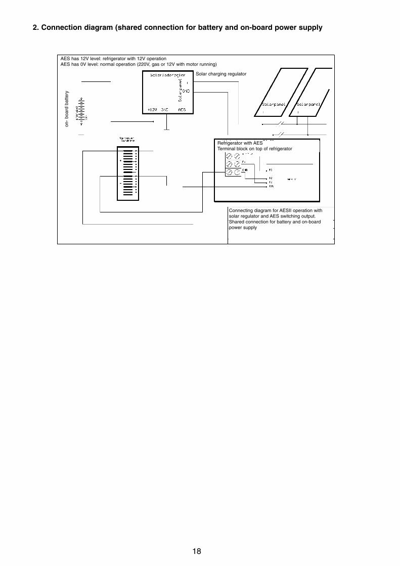
2. Connection diagram (shared connection for battery and on-board power supply
on-
boar
d ba
ttery
Solar charging regulator
AES has 12V level: refrigerator with 12V operationAES has 0V level: normal operation (220V, gas or 12V with motor running)
Refrigerator with AESTerminal block on top of refrigerator
Connecting diagram for AESII operation withsolar regulator and AES switching output.Shared connection for battery and on-boardpower supply

19
©D
omet
ic G
mbH
-
200
2 -
S
ubje
ct t
o ch
ange
with
out
notic
e -
P
rinte
d in
Ger
man
yDometic GmbH
Technisches Büro / Service DokumentationIn der Steinwiese 16
D-57074 Siegen
Tel.: +49-(0) 271 / 692-0Fax.: +49-(0) 271 / 692 - 300
www.dometic.de/caravanwww.dometic.com