
Service Guide - IBMpublib.boulder.ibm.com/systems/hardware_docs/pdf/232725.pdfviii Service Guide...
350
7013 J Series Service Guide
Transcript of Service Guide - IBMpublib.boulder.ibm.com/systems/hardware_docs/pdf/232725.pdfviii Service Guide...

7013 J Series
Service Guide

Third Edition (April 1997)
This edition notice applies to the 7013 J Series Service Guide. This edition obsoletes all previous editions.
The following paragraph does not apply to the United Kingdom or any country where suchprovisions are inconsistent with local law: THIS PUBLICATION IS PRINTED “AS IS” WITHOUTWARRANTY OF ANY KIND, EITHER EXPRESS OR IMPLIED, INCLUDING, BUT NOT LIMITED TO, THEIMPLIED WARRANTIES OF MERCHANTABILITY OR FITNESS FOR A PARTICULAR PURPOSE. Somestates do not allow disclaimer of express or implied warranties in certain transactions; therefore, thisstatement may not apply to you.
This publication could include technical inaccuracies or typographical errors. Changes are periodically madeto the information herein; these changes will be incorporated in new editions of the publication. Themanufacturer may make improvements and/or changes in the product(s) and/or program(s) described in thispublication at any time, without notice.
It is possible that this publication may contain reference to, or information about, products (machines andprograms), programming, or services that are not announced in your country. Such references or informationmust not be construed to mean that such products, programming, or services will be offered in your country.Any reference to a licensed program in this publication is not intended to state or imply that you can use onlythe licensed program indicated. You can use any functionally equivalent program instead.
AIX is a registered trademark of International Business Machines.
Medeco is a trademark of the Medeco Company.
Micro Channel is a trademark of International Business Machines.
SystemGuard is a trademark of International Business Machines.
Velcro is a trademark of Velcro Industries.
Copyright International Business Machines Corporation, 1994, 1997. All rights reserved.
Note to U.S. Government Users – Documentation and programs related to restricted rights – Use,duplication, or disclosure is subject to the restrictions set forth in the GSA ADP Schedule Contract.

Preface iii
Table of Contents
Communications Statements vii. . . . . . . . . . . . . . . . . . . . . . . . . . . . . . . . . . . . . . . . . . . .
Safety Notices xi. . . . . . . . . . . . . . . . . . . . . . . . . . . . . . . . . . . . . . . . . . . . . . . . . . . . . . . . . .
About This Book xiii. . . . . . . . . . . . . . . . . . . . . . . . . . . . . . . . . . . . . . . . . . . . . . . . . . . . . . . .
Chapter 1. 7013 J Series Unit Descriptions 1-1. . . . . . . . . . . . . . . . . . . . . . . . . . . . . . . The 7013 J Series Base Unit 1-1. . . . . . . . . . . . . . . . . . . . . . . . . . . . . . . . . . . . . . . . . . . . . .
Base Unit SCSI Buses 1-2. . . . . . . . . . . . . . . . . . . . . . . . . . . . . . . . . . . . . . . . . . . . . . . . . Micro Channel Adapter (MCA) Card Cage 1-3. . . . . . . . . . . . . . . . . . . . . . . . . . . . . . . . SCSI Overview 1-3. . . . . . . . . . . . . . . . . . . . . . . . . . . . . . . . . . . . . . . . . . . . . . . . . . . . . . . . SCSI Data and Power Flow 1-4. . . . . . . . . . . . . . . . . . . . . . . . . . . . . . . . . . . . . . . . . . . . .
Internal Connectors 1-5. . . . . . . . . . . . . . . . . . . . . . . . . . . . . . . . . . . . . . . . . . . . . . . . . . . . . . Base Unit Back Plane 1-5. . . . . . . . . . . . . . . . . . . . . . . . . . . . . . . . . . . . . . . . . . . . . . . . . . SCSI Device Locations 1-7. . . . . . . . . . . . . . . . . . . . . . . . . . . . . . . . . . . . . . . . . . . . . . . . . I/O Card 1-8. . . . . . . . . . . . . . . . . . . . . . . . . . . . . . . . . . . . . . . . . . . . . . . . . . . . . . . . . . . . . . System Planar 1-9. . . . . . . . . . . . . . . . . . . . . . . . . . . . . . . . . . . . . . . . . . . . . . . . . . . . . . . . MCA Planar (Base Unit) 1-10. . . . . . . . . . . . . . . . . . . . . . . . . . . . . . . . . . . . . . . . . . . . . . . . Cluster Power Control 1-11. . . . . . . . . . . . . . . . . . . . . . . . . . . . . . . . . . . . . . . . . . . . . . . . . .
Description of the Base Unit Hardware Components 1-12. . . . . . . . . . . . . . . . . . . . . . . . . . Base Unit Front 1-12. . . . . . . . . . . . . . . . . . . . . . . . . . . . . . . . . . . . . . . . . . . . . . . . . . . . . . . Base Unit Rear 1-16. . . . . . . . . . . . . . . . . . . . . . . . . . . . . . . . . . . . . . . . . . . . . . . . . . . . . . . .
Description of the 7013 J Series Expansion Unit 1-24. . . . . . . . . . . . . . . . . . . . . . . . . . . . . Expansion Unit SCSI Buses 1-26. . . . . . . . . . . . . . . . . . . . . . . . . . . . . . . . . . . . . . . . . . . . Micro Channel Adapter (MCA) Card Cage 1-27. . . . . . . . . . . . . . . . . . . . . . . . . . . . . . . . SCSI Controllers 1-28. . . . . . . . . . . . . . . . . . . . . . . . . . . . . . . . . . . . . . . . . . . . . . . . . . . . . . MCA Expansion Planar (MPe) 1-29. . . . . . . . . . . . . . . . . . . . . . . . . . . . . . . . . . . . . . . . . . . Expansion Unit Back Plane 1-30. . . . . . . . . . . . . . . . . . . . . . . . . . . . . . . . . . . . . . . . . . . . .
Description of the Expansion Unit Hardware Components 1-32. . . . . . . . . . . . . . . . . . . . . Expansion Unit Front 1-32. . . . . . . . . . . . . . . . . . . . . . . . . . . . . . . . . . . . . . . . . . . . . . . . . . . Expansion Unit Rear 1-33. . . . . . . . . . . . . . . . . . . . . . . . . . . . . . . . . . . . . . . . . . . . . . . . . . .
7013 J Series Power Flow 1-35. . . . . . . . . . . . . . . . . . . . . . . . . . . . . . . . . . . . . . . . . . . . . . . . 7013 J Series Data Flow 1-36. . . . . . . . . . . . . . . . . . . . . . . . . . . . . . . . . . . . . . . . . . . . . . . . . . Specifications 1-38. . . . . . . . . . . . . . . . . . . . . . . . . . . . . . . . . . . . . . . . . . . . . . . . . . . . . . . . . . .
Dimensions 1-38. . . . . . . . . . . . . . . . . . . . . . . . . . . . . . . . . . . . . . . . . . . . . . . . . . . . . . . . . . . Weight 1-38. . . . . . . . . . . . . . . . . . . . . . . . . . . . . . . . . . . . . . . . . . . . . . . . . . . . . . . . . . . . . . . Relative Humidity 1-38. . . . . . . . . . . . . . . . . . . . . . . . . . . . . . . . . . . . . . . . . . . . . . . . . . . . . . Environment Temperature 1-38. . . . . . . . . . . . . . . . . . . . . . . . . . . . . . . . . . . . . . . . . . . . . . Input Power 1-38. . . . . . . . . . . . . . . . . . . . . . . . . . . . . . . . . . . . . . . . . . . . . . . . . . . . . . . . . . . Power Supply Output Power 1-39. . . . . . . . . . . . . . . . . . . . . . . . . . . . . . . . . . . . . . . . . . . . Power Supply Output Load 1-39. . . . . . . . . . . . . . . . . . . . . . . . . . . . . . . . . . . . . . . . . . . . . Operating Voltage (Auto ranging) 1-39. . . . . . . . . . . . . . . . . . . . . . . . . . . . . . . . . . . . . . . . Heat Output 1-39. . . . . . . . . . . . . . . . . . . . . . . . . . . . . . . . . . . . . . . . . . . . . . . . . . . . . . . . . . Acoustic Noise 1-39. . . . . . . . . . . . . . . . . . . . . . . . . . . . . . . . . . . . . . . . . . . . . . . . . . . . . . . . Safety Standards 1-39. . . . . . . . . . . . . . . . . . . . . . . . . . . . . . . . . . . . . . . . . . . . . . . . . . . . . . ECM/EMI Standards 1-39. . . . . . . . . . . . . . . . . . . . . . . . . . . . . . . . . . . . . . . . . . . . . . . . . . .
iv Service Guide
Power Cables 1-40. . . . . . . . . . . . . . . . . . . . . . . . . . . . . . . . . . . . . . . . . . . . . . . . . . . . . . . . . . . Checking Customer Outlets 1-41. . . . . . . . . . . . . . . . . . . . . . . . . . . . . . . . . . . . . . . . . . . . . . . Service Inspection Guide 1-42. . . . . . . . . . . . . . . . . . . . . . . . . . . . . . . . . . . . . . . . . . . . . . . . . Installation Checkout 1-43. . . . . . . . . . . . . . . . . . . . . . . . . . . . . . . . . . . . . . . . . . . . . . . . . . . . .
Installation Checkout Procedure 1-43. . . . . . . . . . . . . . . . . . . . . . . . . . . . . . . . . . . . . . . . .
Chapter 2. Using SystemGuard 2-1. . . . . . . . . . . . . . . . . . . . . . . . . . . . . . . . . . . . . . . . . . Introduction 2-1. . . . . . . . . . . . . . . . . . . . . . . . . . . . . . . . . . . . . . . . . . . . . . . . . . . . . . . . . . . . . SystemGuard Power 2-2. . . . . . . . . . . . . . . . . . . . . . . . . . . . . . . . . . . . . . . . . . . . . . . . . . . . . SystemGuard Components 2-2. . . . . . . . . . . . . . . . . . . . . . . . . . . . . . . . . . . . . . . . . . . . . . . SystemGuard Bring-Up MicroProcessor Overview 2-2. . . . . . . . . . . . . . . . . . . . . . . . . . . . The Operator Panel 2-3. . . . . . . . . . . . . . . . . . . . . . . . . . . . . . . . . . . . . . . . . . . . . . . . . . . . . . SystemGuard Consoles 2-4. . . . . . . . . . . . . . . . . . . . . . . . . . . . . . . . . . . . . . . . . . . . . . . . . . Physical and Electronic Key 2-4. . . . . . . . . . . . . . . . . . . . . . . . . . . . . . . . . . . . . . . . . . . . . . . SystemGuard Phases 2-4. . . . . . . . . . . . . . . . . . . . . . . . . . . . . . . . . . . . . . . . . . . . . . . . . . . .
Stand-By Phase 2-4. . . . . . . . . . . . . . . . . . . . . . . . . . . . . . . . . . . . . . . . . . . . . . . . . . . . . . . Init Phase 2-5. . . . . . . . . . . . . . . . . . . . . . . . . . . . . . . . . . . . . . . . . . . . . . . . . . . . . . . . . . . . Maintenance Phase 2-5. . . . . . . . . . . . . . . . . . . . . . . . . . . . . . . . . . . . . . . . . . . . . . . . . . . . Boot Phase 2-5. . . . . . . . . . . . . . . . . . . . . . . . . . . . . . . . . . . . . . . . . . . . . . . . . . . . . . . . . . . Run-Time Phase 2-5. . . . . . . . . . . . . . . . . . . . . . . . . . . . . . . . . . . . . . . . . . . . . . . . . . . . . . SystemGuard Parameters and Flags 2-9. . . . . . . . . . . . . . . . . . . . . . . . . . . . . . . . . . . . . Working with SystemGuard 2-10. . . . . . . . . . . . . . . . . . . . . . . . . . . . . . . . . . . . . . . . . . . . . SystemGuard Menus 2-11. . . . . . . . . . . . . . . . . . . . . . . . . . . . . . . . . . . . . . . . . . . . . . . . . . Maintenance Menu 2-21. . . . . . . . . . . . . . . . . . . . . . . . . . . . . . . . . . . . . . . . . . . . . . . . . . . . Display Configuration 2-22. . . . . . . . . . . . . . . . . . . . . . . . . . . . . . . . . . . . . . . . . . . . . . . . . . Display BUMP Error Log 2-25. . . . . . . . . . . . . . . . . . . . . . . . . . . . . . . . . . . . . . . . . . . . . . . Enable Service Console 2-25. . . . . . . . . . . . . . . . . . . . . . . . . . . . . . . . . . . . . . . . . . . . . . . . Disable Service Console 2-25. . . . . . . . . . . . . . . . . . . . . . . . . . . . . . . . . . . . . . . . . . . . . . . Reset 2-25. . . . . . . . . . . . . . . . . . . . . . . . . . . . . . . . . . . . . . . . . . . . . . . . . . . . . . . . . . . . . . . . Power-Off 2-25. . . . . . . . . . . . . . . . . . . . . . . . . . . . . . . . . . . . . . . . . . . . . . . . . . . . . . . . . . . . System Boot 2-26. . . . . . . . . . . . . . . . . . . . . . . . . . . . . . . . . . . . . . . . . . . . . . . . . . . . . . . . . . Off-Line Tests 2-28. . . . . . . . . . . . . . . . . . . . . . . . . . . . . . . . . . . . . . . . . . . . . . . . . . . . . . . . . Set Parameters 2-32. . . . . . . . . . . . . . . . . . . . . . . . . . . . . . . . . . . . . . . . . . . . . . . . . . . . . . . Set National Language 2-38. . . . . . . . . . . . . . . . . . . . . . . . . . . . . . . . . . . . . . . . . . . . . . . . . Some Common SystemGuard Tasks 2-39. . . . . . . . . . . . . . . . . . . . . . . . . . . . . . . . . . . . . Customizing SystemGuard For Your Needs 2-58. . . . . . . . . . . . . . . . . . . . . . . . . . . . . . . Reloading the Flash EEPROM 2-60. . . . . . . . . . . . . . . . . . . . . . . . . . . . . . . . . . . . . . . . . .
Chapter 3. Maintenance Analysis Procedures (MAPs) 3-1520-1. . . . . . . . . . . . . . . . . . . . . MAP 1520: 7013 J Series Power MAP 3-1520-1. . . . . . . . . . . . . . . . . . . . . . . . . . . . . . . . . . . . . . MAP 1540: 7013 J Series System Unit - Minimum Configuration 3-1540-1. . . . . . . . . . . . . . .
Preface v
Chapter 4. Removal and Replacement Procedures 4-1. . . . . . . . . . . . . . . . . . . . . . . . Tools Needed for Service 4-2. . . . . . . . . . . . . . . . . . . . . . . . . . . . . . . . . . . . . . . . . . . . . . . . . Preliminary Operations 4-2. . . . . . . . . . . . . . . . . . . . . . . . . . . . . . . . . . . . . . . . . . . . . . . . . . . Rear Cover 4-4. . . . . . . . . . . . . . . . . . . . . . . . . . . . . . . . . . . . . . . . . . . . . . . . . . . . . . . . . . . . . Front Door 4-6. . . . . . . . . . . . . . . . . . . . . . . . . . . . . . . . . . . . . . . . . . . . . . . . . . . . . . . . . . . . . . Front Cover 4-7. . . . . . . . . . . . . . . . . . . . . . . . . . . . . . . . . . . . . . . . . . . . . . . . . . . . . . . . . . . . . Top Cover 4-10. . . . . . . . . . . . . . . . . . . . . . . . . . . . . . . . . . . . . . . . . . . . . . . . . . . . . . . . . . . . . . Side Covers 4-13. . . . . . . . . . . . . . . . . . . . . . . . . . . . . . . . . . . . . . . . . . . . . . . . . . . . . . . . . . . . . Adapters 4-15. . . . . . . . . . . . . . . . . . . . . . . . . . . . . . . . . . . . . . . . . . . . . . . . . . . . . . . . . . . . . . . . Expansion Unit Operator Panel and Power-on Light 4-23. . . . . . . . . . . . . . . . . . . . . . . . . . MCA Planar 4-24. . . . . . . . . . . . . . . . . . . . . . . . . . . . . . . . . . . . . . . . . . . . . . . . . . . . . . . . . . . . . Base Unit Operator Panel 4-26. . . . . . . . . . . . . . . . . . . . . . . . . . . . . . . . . . . . . . . . . . . . . . . . . 3.5-Inch Diskette Drive 4-28. . . . . . . . . . . . . . . . . . . . . . . . . . . . . . . . . . . . . . . . . . . . . . . . . . . Lithium Battery 4-30. . . . . . . . . . . . . . . . . . . . . . . . . . . . . . . . . . . . . . . . . . . . . . . . . . . . . . . . . . Operator Panel Bezel 4-32. . . . . . . . . . . . . . . . . . . . . . . . . . . . . . . . . . . . . . . . . . . . . . . . . . . . Media Drives 4-34. . . . . . . . . . . . . . . . . . . . . . . . . . . . . . . . . . . . . . . . . . . . . . . . . . . . . . . . . . . . Unconfiguring or Configuring a Drive 4-36. . . . . . . . . . . . . . . . . . . . . . . . . . . . . . . . . . . . . . . Media Drives (Carrier, Drive) 4-37. . . . . . . . . . . . . . . . . . . . . . . . . . . . . . . . . . . . . . . . . . . . . . Disk Drives 4-40. . . . . . . . . . . . . . . . . . . . . . . . . . . . . . . . . . . . . . . . . . . . . . . . . . . . . . . . . . . . . Disk Drives, (Carrier, 8 bit Disk Drive) 4-44. . . . . . . . . . . . . . . . . . . . . . . . . . . . . . . . . . . . . . Disk Drives (Carrier, 16 bit Disk Drive) 4-48. . . . . . . . . . . . . . . . . . . . . . . . . . . . . . . . . . . . . . Power Supply 4-51. . . . . . . . . . . . . . . . . . . . . . . . . . . . . . . . . . . . . . . . . . . . . . . . . . . . . . . . . . . Fan Screens 4-55. . . . . . . . . . . . . . . . . . . . . . . . . . . . . . . . . . . . . . . . . . . . . . . . . . . . . . . . . . . . Main Fan Module 4-56. . . . . . . . . . . . . . . . . . . . . . . . . . . . . . . . . . . . . . . . . . . . . . . . . . . . . . . . Disks Fan Module 4-58. . . . . . . . . . . . . . . . . . . . . . . . . . . . . . . . . . . . . . . . . . . . . . . . . . . . . . . . MCA Fan Module 4-60. . . . . . . . . . . . . . . . . . . . . . . . . . . . . . . . . . . . . . . . . . . . . . . . . . . . . . . . Individual Fans 4-64. . . . . . . . . . . . . . . . . . . . . . . . . . . . . . . . . . . . . . . . . . . . . . . . . . . . . . . . . . System Interface Board 4-67. . . . . . . . . . . . . . . . . . . . . . . . . . . . . . . . . . . . . . . . . . . . . . . . . . . Base Unit CPU Module 4-70. . . . . . . . . . . . . . . . . . . . . . . . . . . . . . . . . . . . . . . . . . . . . . . . . . . Base Unit I/O, CPU and Memory Cards 4-73. . . . . . . . . . . . . . . . . . . . . . . . . . . . . . . . . . . . . Memory Modules 4-78. . . . . . . . . . . . . . . . . . . . . . . . . . . . . . . . . . . . . . . . . . . . . . . . . . . . . . . . System Planar 4-80. . . . . . . . . . . . . . . . . . . . . . . . . . . . . . . . . . . . . . . . . . . . . . . . . . . . . . . . . . . Expansion Unit SCSI Interface Card 4-82. . . . . . . . . . . . . . . . . . . . . . . . . . . . . . . . . . . . . . . . Base Unit First SCSI Bus Connection 4-84. . . . . . . . . . . . . . . . . . . . . . . . . . . . . . . . . . . . . . . Base Unit Second SCSI Bus Connection 4-87. . . . . . . . . . . . . . . . . . . . . . . . . . . . . . . . . . . . Main Power Switch 4-90. . . . . . . . . . . . . . . . . . . . . . . . . . . . . . . . . . . . . . . . . . . . . . . . . . . . . . . Base Unit FXB Flex Cable 4-92. . . . . . . . . . . . . . . . . . . . . . . . . . . . . . . . . . . . . . . . . . . . . . . . FXE Flex Cable 4-95. . . . . . . . . . . . . . . . . . . . . . . . . . . . . . . . . . . . . . . . . . . . . . . . . . . . . . . . . . Top Cover Interlock Switch 4-101. . . . . . . . . . . . . . . . . . . . . . . . . . . . . . . . . . . . . . . . . . . . . . . . Back Plane 4-102. . . . . . . . . . . . . . . . . . . . . . . . . . . . . . . . . . . . . . . . . . . . . . . . . . . . . . . . . . . . . Stability Support 4-105. . . . . . . . . . . . . . . . . . . . . . . . . . . . . . . . . . . . . . . . . . . . . . . . . . . . . . . . .
vi Service Guide
Chapter 5. Parts Information 5-1. . . . . . . . . . . . . . . . . . . . . . . . . . . . . . . . . . . . . . . . . . . . . Acronyms for FRU Parts 5-1. . . . . . . . . . . . . . . . . . . . . . . . . . . . . . . . . . . . . . . . . . . . . . . .
Base Unit and Expansion Unit Front View (without covers) 5-2. . . . . . . . . . . . . . . . . . . . Base Unit Rear View (without covers) 5-4. . . . . . . . . . . . . . . . . . . . . . . . . . . . . . . . . . . . . . Base Unit CPU Module (without the cover) 5-6. . . . . . . . . . . . . . . . . . . . . . . . . . . . . . . . . . Expansion Unit Rear View (without covers) 5-8. . . . . . . . . . . . . . . . . . . . . . . . . . . . . . . . . . Base Unit Internal Cables 5-10. . . . . . . . . . . . . . . . . . . . . . . . . . . . . . . . . . . . . . . . . . . . . . . . . Expansion Unit Internal Cables 5-12. . . . . . . . . . . . . . . . . . . . . . . . . . . . . . . . . . . . . . . . . . . . Covers 5-14. . . . . . . . . . . . . . . . . . . . . . . . . . . . . . . . . . . . . . . . . . . . . . . . . . . . . . . . . . . . . . . . . Power Cables and Plugs 5-15. . . . . . . . . . . . . . . . . . . . . . . . . . . . . . . . . . . . . . . . . . . . . . . . . .
Appendix A. SystemGuard Test Groups A-1. . . . . . . . . . . . . . . . . . . . . . . . . . . . . . . . . . SystemGuard Test Groups Table A-1. . . . . . . . . . . . . . . . . . . . . . . . . . . . . . . . . . . . . . . . . . . SystemGuard Test Group Descriptions A-3. . . . . . . . . . . . . . . . . . . . . . . . . . . . . . . . . . . . .
BUMP Quick I/O Tests Group A-3. . . . . . . . . . . . . . . . . . . . . . . . . . . . . . . . . . . . . . . . . . . JTAG Test Group A-8. . . . . . . . . . . . . . . . . . . . . . . . . . . . . . . . . . . . . . . . . . . . . . . . . . . . . . Direct I/O Test Group A-8. . . . . . . . . . . . . . . . . . . . . . . . . . . . . . . . . . . . . . . . . . . . . . . . . . CPU Test Group A-11. . . . . . . . . . . . . . . . . . . . . . . . . . . . . . . . . . . . . . . . . . . . . . . . . . . . . . . DCB and Memory Test Group A-12. . . . . . . . . . . . . . . . . . . . . . . . . . . . . . . . . . . . . . . . . . . Interrupt Tests Group A-19. . . . . . . . . . . . . . . . . . . . . . . . . . . . . . . . . . . . . . . . . . . . . . . . . . CPU MultiProcessor Test Group A-20. . . . . . . . . . . . . . . . . . . . . . . . . . . . . . . . . . . . . . . . .
Appendix B. Modifying SystemGuard Parameters B-1. . . . . . . . . . . . . . . . . . . . . . . . . Default Parameter Values B-1. . . . . . . . . . . . . . . . . . . . . . . . . . . . . . . . . . . . . . . . . . . . . . . . . Changing Flags and Parameters Under AIX Service Aids B-3. . . . . . . . . . . . . . . . . . . . . Modifying the Remote Authorization Flag B-3. . . . . . . . . . . . . . . . . . . . . . . . . . . . . . . . . . . Modifying the Dial-Out Authorization Flag B-4. . . . . . . . . . . . . . . . . . . . . . . . . . . . . . . . . . . Modifying Dial-In Phone Numbers B-5. . . . . . . . . . . . . . . . . . . . . . . . . . . . . . . . . . . . . . . . . . Modifying Dial-Out Phone Numbers B-5. . . . . . . . . . . . . . . . . . . . . . . . . . . . . . . . . . . . . . . . Modifying the Electronic Mode Switch from Service Line Flag B-6. . . . . . . . . . . . . . . . . . Reloading the Flash EEPROM B-7. . . . . . . . . . . . . . . . . . . . . . . . . . . . . . . . . . . . . . . . . . . . .
Appendix C. SystemGuard Remote Operation Configuration C-1. . . . . . . . . . . . . . . Terminal Configuration C-1. . . . . . . . . . . . . . . . . . . . . . . . . . . . . . . . . . . . . . . . . . . . . . . . . . . . Flags and Parameters Settings C-2. . . . . . . . . . . . . . . . . . . . . . . . . . . . . . . . . . . . . . . . . . . . Modem Configuration Files C-4. . . . . . . . . . . . . . . . . . . . . . . . . . . . . . . . . . . . . . . . . . . . . . . . Initializing a Modem C-6. . . . . . . . . . . . . . . . . . . . . . . . . . . . . . . . . . . . . . . . . . . . . . . . . . . . . . Testing Dial-Out C-6. . . . . . . . . . . . . . . . . . . . . . . . . . . . . . . . . . . . . . . . . . . . . . . . . . . . . . . . .
Appendix D. Off Line Diagnostic Error Codes D-1. . . . . . . . . . . . . . . . . . . . . . . . . . . . . Error Logging D-26. . . . . . . . . . . . . . . . . . . . . . . . . . . . . . . . . . . . . . . . . . . . . . . . . . . . . . . . . . .
Appendix E. SRN 409-098 Cover Interlock Diagnosing E-1. . . . . . . . . . . . . . . . . . . . . Further Diagnosis E-1. . . . . . . . . . . . . . . . . . . . . . . . . . . . . . . . . . . . . . . . . . . . . . . . . . . . . . . .
Appendix F. System Power States F-1. . . . . . . . . . . . . . . . . . . . . . . . . . . . . . . . . . . . . . . . Power States F-1. . . . . . . . . . . . . . . . . . . . . . . . . . . . . . . . . . . . . . . . . . . . . . . . . . . . . . . . . . . .
Glossary: Special Terms Used in SystemGuard X-1. . . . . . . . . . . . . . . . . . . . . . . . . . .
Index X-3. . . . . . . . . . . . . . . . . . . . . . . . . . . . . . . . . . . . . . . . . . . . . . . . . . . . . . . . . . . . . . . . . .
Preface vii
Communications Statements
The following statement applies to this product. The statement for other products intendedfor use with this product appears in their accompanying manuals.
Federal Communications Commission (FCC) StatementNote: This equipment has been tested and found to comply with the limits for a Class A
digital device, pursuant to Part 15 of the FCC Rules. These limits are designed toprovide reasonable protection against harmful interference when the equipment isoperated in a commercial environment. This equipment generates, uses, and canradiate radio frequency energy and, if not installed and used in accordance with theinstruction manual, may cause harmful interference to radio communications.Operation of this equipment in a residential area is likely to cause harmfulinterference in which case the user will be required to correct the interference at hisown expense.
Properly shielded and grounded cables and connectors must be used in order to meet FCCemission limits. Neither the provider nor the manufacturer are responsible for any radio ortelevision interference caused by using other than recommended cables and connectors orby unauthorized changes or modifications to this equipment. Unauthorized changes ormodifications could void the user’s authority to operate the equipment.
This device complies with Part 15 of the FCC Rules. Operation is subject to the followingtwo conditions: (1) this device may not cause harmful interference, and (2) this device mustaccept any interference received, including interference that may cause undesiredoperation.
United Kingdom Telecommunications Safety RequirementsThis equipment is manufactured to the International Safety Standard EN60950 and as suchis approved in the UK under the General Approval Number NS/G/1234/J/100003 for indirectconnection to the public telecommunication network.
The network adapter interfaces housed within this equipment are approved separately, eachone having its own independent approval number. These interface adapters, supplied by themanufacturer, do not use or contain excessive voltages. An excessive voltage is one whichexceeds 70.7 V peak ac or 120 V dc. They interface with this equipment using Safe ExtraLow Voltages only. In order to maintain the separate (independent) approval of themanufacturer’s adapters, it is essential that other optional cards, not supplied by themanufacturer, do not use main voltages or any other excessive voltages. Seek advice from acompetent engineer before installing other adapters not supplied by the manufacturer.
International Electrotechnical Commission (IEC) StatementThis product has been designed and built to comply with IEC Standard 950.
viii Service Guide
European Union (EU) StatementThis product is in conformity with the protection requirements of EU Council Directive89/336/EEC on the approximation of the laws of the Member States relating toelectromagnetic compatibility.
Neither the provider nor the manufacturer can accept responsibility for any failure to satisfythe protection requirements resulting from a non-recommended modification of the product,including the fitting of option cards not supplied by the manufacturer.
This product has been tested and found to comply with the limits for Class A InformationTechnology Equipment according to CISPR 22 / European Standard EN 55022. The limitsfor Class A equipment were derived for commercial and industrial environments to providereasonable protection against interference with licensed communication equipment.
Attention: This is a Class A product. In a domestic environment this product may causeradio interference in which case the user may be required to take adequate measures.
Avis de conformité aux normes du ministère des Communications duCanada
Cet appareil numérique de la classe A respecte toutes les exigences du Réglement sur lematériel brouilleur du Canada.
Canadian Department of Communications compliance statementThis Class A digital apparatus meets the requirements of the CanadianInterference-Causing Equipment Regulations.
VCCI Statement
The following is a summary of the VCCI Japanese statement in the box above.
This equipment is in the Class 1 category (information equipment to be used in
commercial and/or industrial areas) and conforms to the standards set by the Vol-
untary Control Council For Interference by Data Processing Equipment and Elec-
tronic Office Machines aimed at preventing radio interference in commercial and/
or industrial areas.
Consequently, when used in a residential area or in an adjacent area thereto, radio
interference may be caused to radios and TV receivers, etc.
Read the instructions for correct handling. VCCI–1.
Preface ix
Radio Protection for GermanyDieses Gerät ist berechtigt in Übereinstimmung mit dem deutschen EMVG vom 9.Nov.92das EG-Konformitätszeichen zu führen.
Der Aussteller der Konformitätserklärung ist die IBM Germany.
Dieses Gerät erfüllt die Bedingungen der EN 55022 Klasse A. Für diese Klasse vonGeräten gilt folgende Bestimmung nach dem EMVG:
Geräte dürfen an Orten, für die sie nicht ausreichend entstört sind, nur mit besondererGenehmigung des Bundesministers für Post und Telekommunikation oder des Bundesamtesfür Post und Telekommunikation betrieben werden. Die Genehmigung wird erteilt, wennkeine elektromagnetischen Störungen zu erwarten sind.
(Auszug aus dem EMVG vom 9.Nov.92, Para.3, Abs.4)
Hinweis:
Dieses Genehmigungsverfahren ist von der Deutschen Bundespost noch nicht veröffentlichtworden.

x Service Guide
Preface xi
Safety Notices
Note: For a translation of these notices, see System Unit Safety Information.
Definitions of Safety NoticesA danger notice indicates the presence of a hazard that has the potential of causing deathor serious personal injury. Danger notices appear on the following pages:
3-1520-14-14-51
A caution notice indicates the presence of a hazard that has the potential of causingmoderate or minor personal injury. Caution notices appear on the following pages:
3-1520-14-14-30
xii Service Guide
Laser Safety InformationThe optical drive in this system unit is a laser product. The optical drive has a label thatidentifies its classification. The label, located on the drive, is shown below.
CLASS 1 LASER PRODUCTLASER KLASSE 1LUOKAN 1 LASERLAITEAPPAREIL A LASER DE CLASSE 1
TO IEC 825:1984 CENELEC EN 60 825:1991
The optical drive in this system unit is certified in the U.S. to conform to the requirements ofthe Department of Health and Human Services 21 Code of Federal Regulations (DHHS 21CFR) Subchapter J for Class 1 laser products. Elsewhere, the drive is certified to conform tothe requirements of the International Electrotechnical Commission (IEC) 825 (1st edition1984) and CENELEC EN 60 825:1991 for Class 1 laser products.
CAUTION:A class 3 laser is contained in the device. Do not attempt to operate the drive while itis disassembled. Do not attempt to open the covers of the drive as it is notserviceable and is to be replaced as a unit.
Class 1 laser products are not considered to be hazardous. The optical drive containsinternally a Class 3B gallium-arsenide laser that is nominally 30 milliwatts at 830nanometers. The design incorporates a combination of enclosures, electronics, andredundant interlocks such that there is no exposure to laser radiation above a Class 1 levelduring normal operation, user maintenance, or servicing conditions.
Preface xiii
About This Book
This book applies only to the 7013 J Series system units. For other 7013 models see 7013500 Series Installation and Service Guide.
How to Use This BookThis book is used by the service technician to repair system failures. This book assumesthat the service technician is trained on the 7013 J Series system unit.
This book contains Maintenance Analysis Procedures (MAPs) that are not common to othersystems. MAPs that are common to all systems are contained in Diagnostic Information ForMicro Channel Bus Systems.
ISO 9000ISO 9000 registered quality systems were used in the development and manufacturing ofthis product.
Related PublicationsThe Diagnostic Information For Micro Channel Bus Systems, form number SA23-2765,contains the maintenance information and procedures that are common to all systems. Theinformation and procedures in this section apply to any system unit that uses the DiagnosticPrograms.
Adapters, Devices, and Cable Information, form number SA23-2764, contains referenceinformation about adapters, devices, and cabling for the system units. This section alsocontains the removal and replacement procedures for the logic boards on the disk drivesand provides the service representative pin-out lists and cabling information to use inisolating problems with customer cabling.
System Unit Safety Information, form number SA23-2652, contains translated versions ofthe danger and caution notices.
The 7013 J Series Operator Guide, form number SA23-2724, provides information about thecontrols and features of the system unit.
The 7013 J Series Base Unit Hardware Setup Procedure, form number SA23-2723, and7013 J Series Expansion Unit Hardware Setup Procedure, form number SA23-2726 containinformation about setting up your 7013 J Series system unit.

xiv Service Guide
7013 J Series Unit Descriptions 1-1
Chapter 1. 7013 J Series Unit Descriptions
The 7013 J Series system consists of one or two units according to the configuration. Theunits that can be installed are:
• The base unit
• One optional expansion unit.
The minimum configuration consists of the base unit only.
The maximum configuration consists of the base unit and the expansion unit.
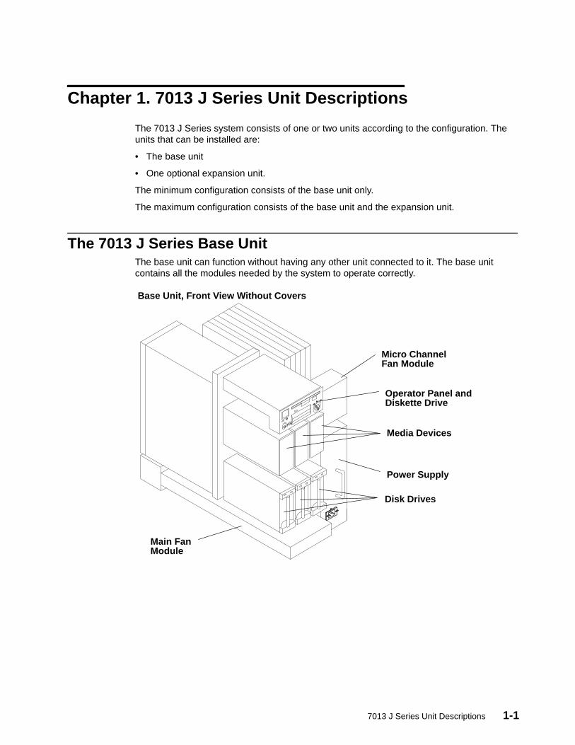
The 7013 J Series Base UnitThe base unit can function without having any other unit connected to it. The base unitcontains all the modules needed by the system to operate correctly.
Main FanModule
Disk Drives
Power Supply
Media Devices
Operator Panel andDiskette Drive
Micro ChannelFan Module
Base Unit, Front View Without Covers
1-2 Service Guide
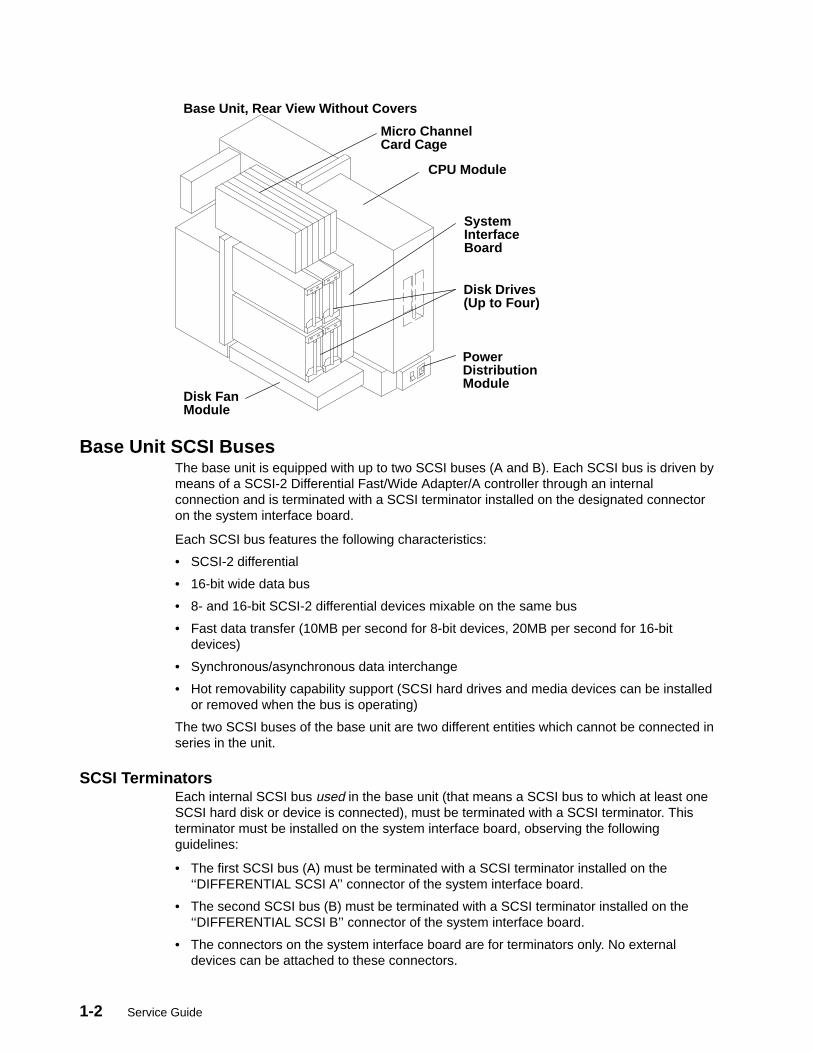
Disk Drives(Up to Four)
Micro ChannelCard Cage
SystemInterfaceBoard
CPU Module
PowerDistributionModule
Disk FanModule
Base Unit, Rear View Without Covers
Base Unit SCSI BusesThe base unit is equipped with up to two SCSI buses (A and B). Each SCSI bus is driven bymeans of a SCSI-2 Differential Fast/Wide Adapter/A controller through an internalconnection and is terminated with a SCSI terminator installed on the designated connectoron the system interface board.
Each SCSI bus features the following characteristics:
• SCSI-2 differential
• 16-bit wide data bus
• 8- and 16-bit SCSI-2 differential devices mixable on the same bus
• Fast data transfer (10MB per second for 8-bit devices, 20MB per second for 16-bitdevices)
• Synchronous/asynchronous data interchange
• Hot removability capability support (SCSI hard drives and media devices can be installedor removed when the bus is operating)
The two SCSI buses of the base unit are two different entities which cannot be connected inseries in the unit.
SCSI TerminatorsEach internal SCSI bus used in the base unit (that means a SCSI bus to which at least oneSCSI hard disk or device is connected), must be terminated with a SCSI terminator. Thisterminator must be installed on the system interface board, observing the followingguidelines:
• The first SCSI bus (A) must be terminated with a SCSI terminator installed on the‘‘DIFFERENTIAL SCSI A’’ connector of the system interface board.
• The second SCSI bus (B) must be terminated with a SCSI terminator installed on the‘‘DIFFERENTIAL SCSI B’’ connector of the system interface board.
• The connectors on the system interface board are for terminators only. No externaldevices can be attached to these connectors.

7013 J Series Unit Descriptions 1-3
Micro Channel Adapter (MCA) Card CageThe MCA card cage is a sub-assembly structure placed in the rear side of both the baseand the expansion unit. It can have up to seven Micro Channel adapters in the base unitand up to eight adapters in the expansion unit.
An MCA planar is located at the bottom of the MCA card cage. This planar is called MCAPlanar (MP) on the base unit, and MCA Expansion Planar (MPe) on the expansion units.
When an MCA slot is not occupied by an adapter, a dummy plate is installed to provideEMC shielding and to protect it from dust or debris. When a new adapter is installed in anavailable slot, the dummy plate must be removed.
On the base unit, the seven slots can be used to install:
• One required SCSI-2 Differential Fast/Wide Adapter/A controller in slot 7
• Up to six supported MCA adapters, which can be installed in any of the remaining slots.
Adapters7013 J Series systems support a variety of MCA adapters (including the SCSI-2 DifferentialFast/Wide Adapter/A controllers). For a full description of each MCA adapter, refer to theDiagnostic Information For Micro Channel Bus Systems delivered with your system.
SCSI Overview
SCSI ControllersEach SCSI controller manages one SCSI bus. For each SCSI bus used in each unit (thatmeans a SCSI bus to which at least one SCSI disk drive or device is connected), adedicated SCSI controller is required.
The SCSI controller(s) managing the SCSI bus(es) of the base unit must be installed in thebase unit.
The slots dedicated to the SCSI controllers installation in the base unit are shown in thefollowing figure (the first controller in slot 7, the second in slot 6).
Second SCSI Controller (optional)
First SCSI Controller (required)
If a second SCSI controller is required on a unit, this must be installed in slot next to the oneoccupied by the first SCSI controller.
If more than two SCSI controllers are needed in the unit, they can be installed in any freeslot.
1-4 Service Guide
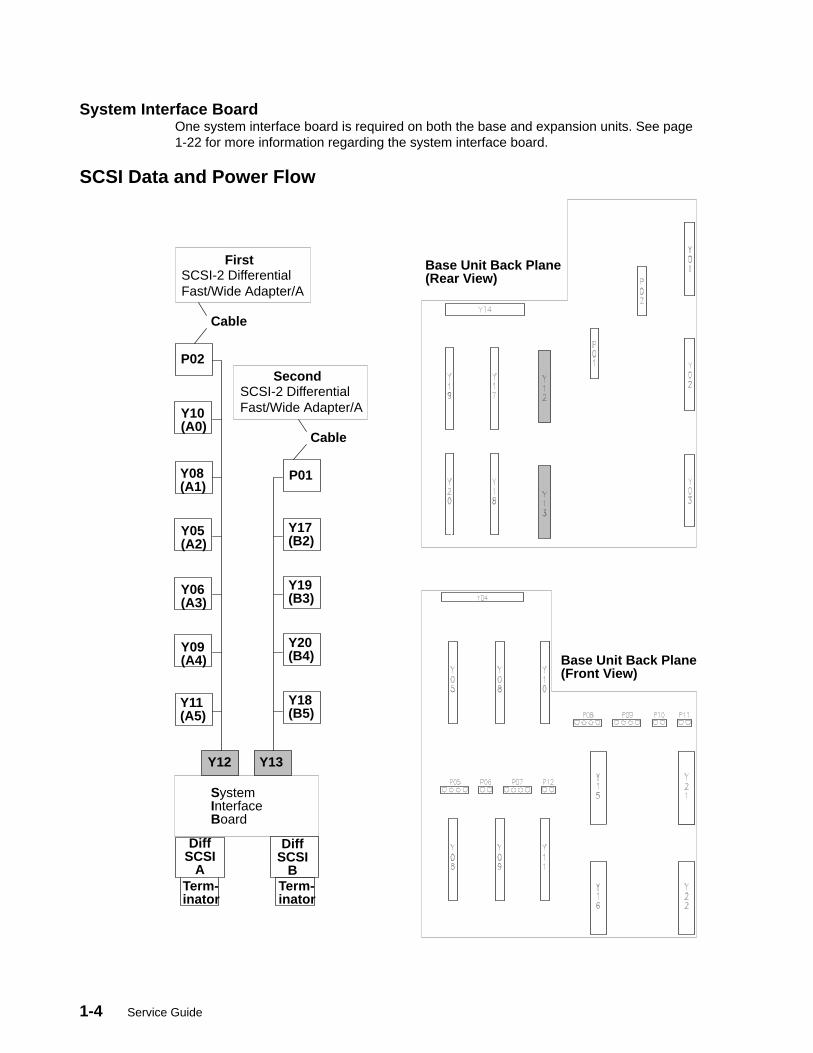
System Interface BoardOne system interface board is required on both the base and expansion units. See page1-22 for more information regarding the system interface board.
SCSI Data and Power Flow
Base Unit Back Plane(Rear View)
Base Unit Back Plane(Front View)
SystemInterfaceBoard
DiffSCSI
A
DiffSCSI
BTerm-inator
SCSI-2 DifferentialFast/Wide Adapter/A
SCSI-2 DifferentialFast/Wide Adapter/A
First
SecondP02
P01
Y10(A0)
Y17(B2)
Y08(A1)
Y19(B3)
Y05(A2)
Y20(B4)
Y06(A3)
Y18(B5)
Y09(A4)
Y13
Y11(A5)
Y12
Term-inator
Cable
Cable
7013 J Series Unit Descriptions 1-5
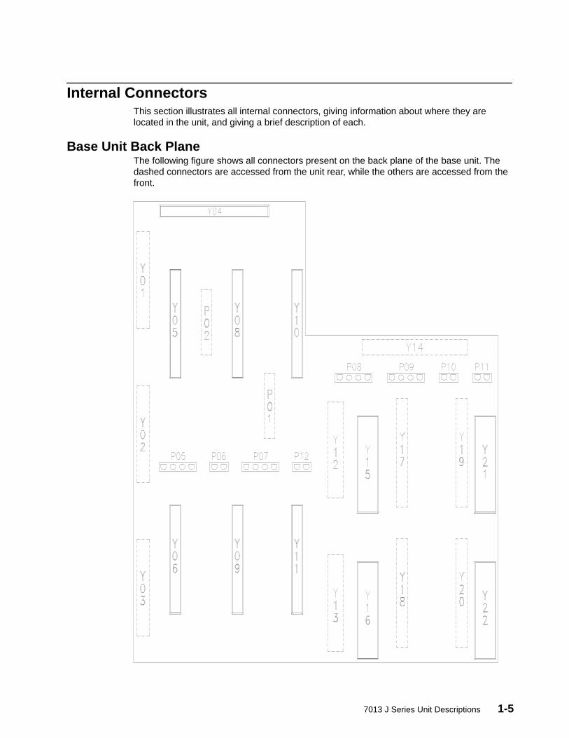
Internal ConnectorsThis section illustrates all internal connectors, giving information about where they arelocated in the unit, and giving a brief description of each.
Base Unit Back PlaneThe following figure shows all connectors present on the back plane of the base unit. Thedashed connectors are accessed from the unit rear, while the others are accessed from thefront.
1-6 Service Guide
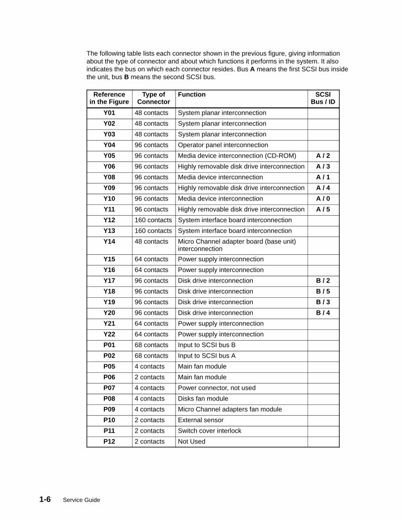
The following table lists each connector shown in the previous figure, giving informationabout the type of connector and about which functions it performs in the system. It alsoindicates the bus on which each connector resides. Bus A means the first SCSI bus insidethe unit, bus B means the second SCSI bus.
Referencein the Figure
Type ofConnector
Function SCSIBus / ID
Y01 48 contacts System planar interconnection
Y02 48 contacts System planar interconnection
Y03 48 contacts System planar interconnection
Y04 96 contacts Operator panel interconnection
Y05 96 contacts Media device interconnection (CD-ROM) A / 2
Y06 96 contacts Highly removable disk drive interconnection A / 3
Y08 96 contacts Media device interconnection A / 1
Y09 96 contacts Highly removable disk drive interconnection A / 4
Y10 96 contacts Media device interconnection A / 0
Y11 96 contacts Highly removable disk drive interconnection A / 5
Y12 160 contacts System interface board interconnection
Y13 160 contacts System interface board interconnection
Y14 48 contacts Micro Channel adapter board (base unit)interconnection
Y15 64 contacts Power supply interconnection
Y16 64 contacts Power supply interconnection
Y17 96 contacts Disk drive interconnection B / 2
Y18 96 contacts Disk drive interconnection B / 5
Y19 96 contacts Disk drive interconnection B / 3
Y20 96 contacts Disk drive interconnection B / 4
Y21 64 contacts Power supply interconnection
Y22 64 contacts Power supply interconnection
P01 68 contacts Input to SCSI bus B
P02 68 contacts Input to SCSI bus A
P05 4 contacts Main fan module
P06 2 contacts Main fan module
P07 4 contacts Power connector, not used
P08 4 contacts Disks fan module
P09 4 contacts Micro Channel adapters fan module
P10 2 contacts External sensor
P11 2 contacts Switch cover interlock
P12 2 contacts Not Used
7013 J Series Unit Descriptions 1-7
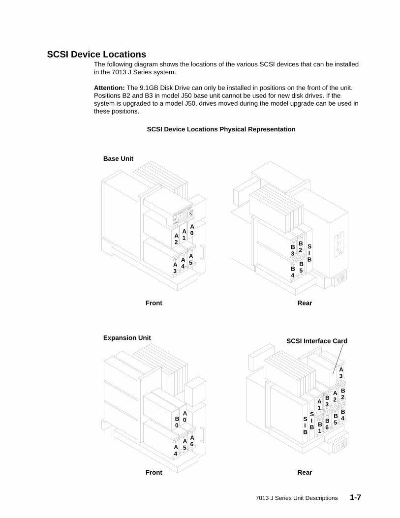
SCSI Device LocationsThe following diagram shows the locations of the various SCSI devices that can be installedin the 7013 J Series system.
Attention: The 9.1GB Disk Drive can only be installed in positions on the front of the unit.Positions B2 and B3 in model J50 base unit cannot be used for new disk drives. If thesystem is upgraded to a model J50, drives moved during the model upgrade can be used inthese positions.
A0A
1A2
A5A
4A3
B2B
3
B5B
4
SIB
B4B
5B6B
1
B2B
3
A2A
1
A3
A6A
5A4
B0
A0
SIB
SIB
SCSI Interface Card
Base Unit
Expansion Unit
Front Rear
SCSI Device Locations Physical Representation
Front Rear
1-8 Service Guide
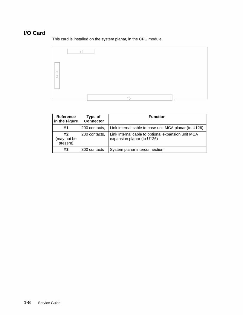
I/O CardThis card is installed on the system planar, in the CPU module.
Referencein the Figure
Type of Connector
Function
Y1 200 contacts, Link internal cable to base unit MCA planar (to U126)
Y2(may not be
present)
200 contacts, Link internal cable to optional expansion unit MCAexpansion planar (to U126)
Y3 300 contacts System planar interconnection
7013 J Series Unit Descriptions 1-9
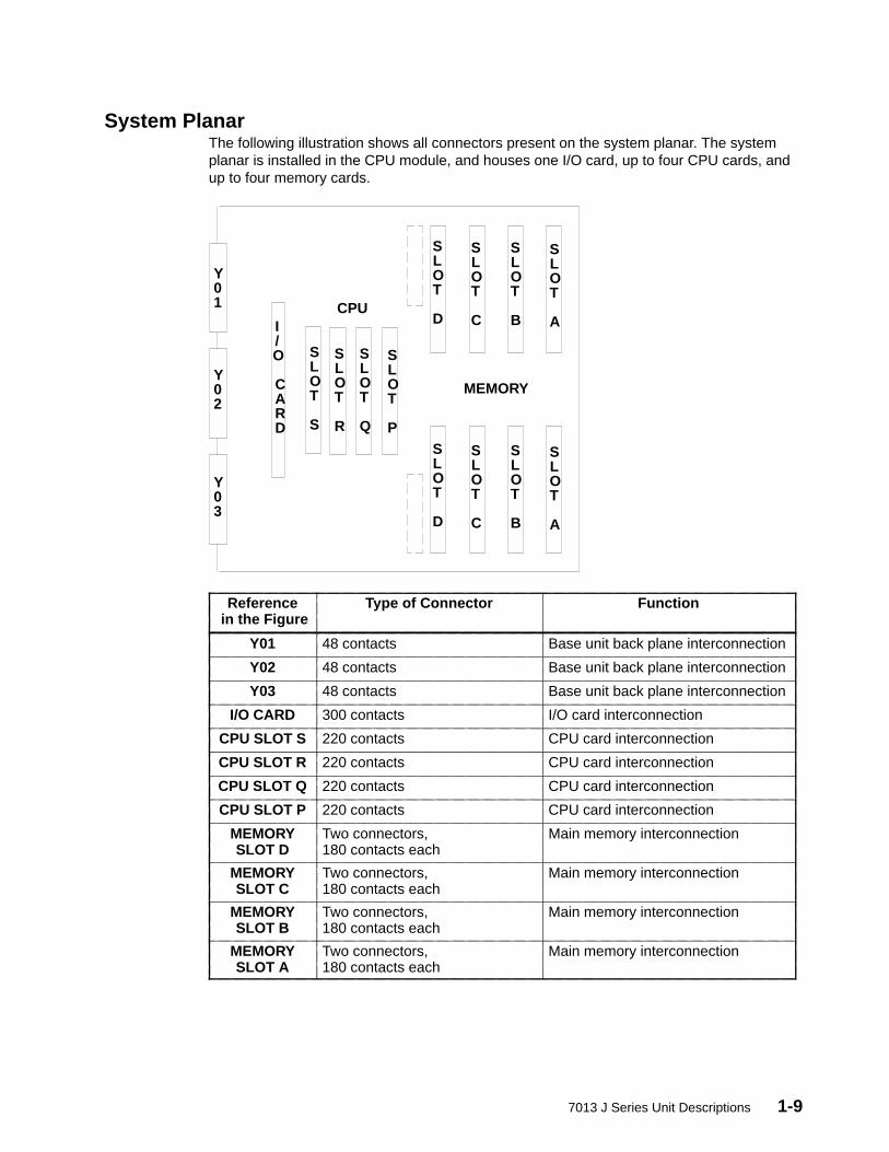
System PlanarThe following illustration shows all connectors present on the system planar. The systemplanar is installed in the CPU module, and houses one I/O card, up to four CPU cards, andup to four memory cards.
I/O CARD
SLOT
D
SLOT
C
SLOT
B
SLOT
A
SLOT
D
SLOT
C
SLOT
B
SLOT
A
SLOT
S
SLOT
R
SLOT
Q
SLOT
P
CPU
MEMORY
Y01
Y02
Y03
Reference in the Figure
Type of Connector Function
Y01 48 contacts Base unit back plane interconnection
Y02 48 contacts Base unit back plane interconnection
Y03 48 contacts Base unit back plane interconnection
I/O CARD 300 contacts I/O card interconnection
CPU SLOT S 220 contacts CPU card interconnection
CPU SLOT R 220 contacts CPU card interconnection
CPU SLOT Q 220 contacts CPU card interconnection
CPU SLOT P 220 contacts CPU card interconnection
MEMORYSLOT D
Two connectors,180 contacts each
Main memory interconnection
MEMORYSLOT C
Two connectors,180 contacts each
Main memory interconnection
MEMORYSLOT B
Two connectors,180 contacts each
Main memory interconnection
MEMORYSLOT A
Two connectors,180 contacts each
Main memory interconnection
1-10 Service Guide
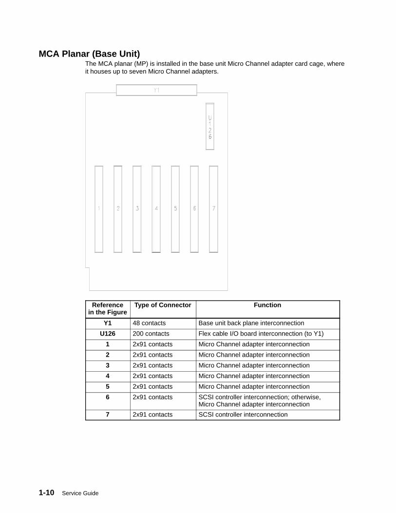
MCA Planar (Base Unit)The MCA planar (MP) is installed in the base unit Micro Channel adapter card cage, whereit houses up to seven Micro Channel adapters.
Referencein the Figure
Type of Connector Function
Y1 48 contacts Base unit back plane interconnection
U126 200 contacts Flex cable I/O board interconnection (to Y1)
1 2x91 contacts Micro Channel adapter interconnection
2 2x91 contacts Micro Channel adapter interconnection
3 2x91 contacts Micro Channel adapter interconnection
4 2x91 contacts Micro Channel adapter interconnection
5 2x91 contacts Micro Channel adapter interconnection
6 2x91 contacts SCSI controller interconnection; otherwise, Micro Channel adapter interconnection
7 2x91 contacts SCSI controller interconnection
7013 J Series Unit Descriptions 1-11
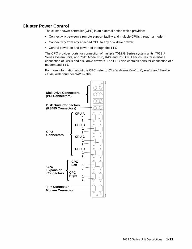
Cluster Power ControlThe cluster power controller (CPC) is an external option which provides:
• Connectivity between a remote support facility and multiple CPUs through a modem
• Connectivity from any attached CPU to any disk drive drawer
• Central power-on and power-off through the TTY.
The CPC provides ports for connection of multiple 7012 G Series system units, 7013 JSeries system units, and 7015 Model R30, R40, and R50 CPU enclosures for interfaceconnection of CPUs and disk drive drawers. The CPC also contains ports for connection of amodem and TTY.
For more information about the CPC, refer to Cluster Power Control Operator and ServiceGuide, order number SA23-2766.
Disk Drive Connectors(PCI Connectors)
Disk Drive Connectors(RS485 Connectors)
CPUConnectors
CPU D
CPU C
CPU B
CPU A1 2
1 2
1 2
1 2
CPCExpansionConnectors
CPCLeft
CPCRight
1 2
1 2
TTY ConnectorModem Connector

1-12 Service Guide
Description of the Base Unit Hardware Components
Base Unit Front
Operator Panel(See page 1-13)
MCA Fan Module(See page 1-14)
Media Devices(See page 1-14)
Power Supply(See page 1-14)
Main Fan Module(See page 1-14)
Disk Drives(See page 1-13)
Back Plane(See page 1-5)
7013 J Series Unit Descriptions 1-13
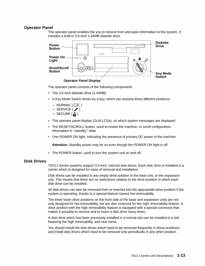
Operator PanelThe operator panel enables the you to receive from and pass information to the system. Itincludes a built-in 3.5-inch 1.44MB diskette drive.
PowerButton
Power OnLight
Reset/ScrollButton
Operator Panel Display
DisketteDrive
Key ModeSwitch
The operator panel consists of the following components:
• The 3.5-inch diskette drive (1.44MB)
• A Key Mode Switch driven by a key, which can assume three different positions:
– NORMAL ( )– SERVICE ( )– SECURE ( )
• The operator panel display (2x16 LCDs), on which system messages are displayed
• The RESET/SCROLL button, used to restart the machine, or scroll configurationinformation in ‘‘standby’’ state
• One POWER ON light, indicating the presence of primary DC power in the machine
Attention: Standby power may be on even though the POWER ON light is off.
• The POWER button, used to turn the system unit on and off.
Disk Drives7013 J Series systems support 3.5-inch, internal disk drives. Each disk drive is installed in acarrier which is designed for ease of removal and installation.
Disk drives can be installed in any empty drive position in the base unit, or the expansionunit. This means that there are no restrictions relative to the drive position in which eachdisk drive can be installed.
All disk drives can also be removed from or inserted into the appropriate drive position if thesystem is operating, thanks to a special feature named hot removability.
The three lower drive positions on the front side of the base and expansion units are notonly designed for hot removability, but are also reserved for the high removability feature. Adrive position with the high removability feature is equipped with a special connector thatmakes it possible to remove and to insert a disk drive many times.
A disk drive which has been previously installed in a normal slot can be installed in a slotfeaturing the high removability, and vice-versa.
You should install the disk drives which need to be removed frequently in these positions,and install disk drives which need to be removed only periodically in any other position.
1-14 Service Guide
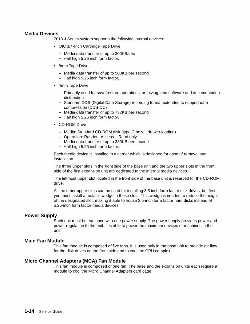
Media Devices7013 J Series system supports the following internal devices:
• QIC 1/4-Inch Cartridge Tape Drive
– Media data transfer of up to 300KB/sec– Half high 5.25 inch form factor.
• 8mm Tape Drive
– Media data transfer of up to 500KB per second– Half high 5.25 inch form factor.
• 4mm Tape Drive
– Primarily used for save/restore operations, archiving, and software and documentationdistribution
– Standard DDS (Digital Data Storage) recording format extended to support datacompression (DDS-DC)
– Media data transfer of up to 732KB per second– Half high 5.25 inch form factor.
• CD-ROM Drive
– Media: Standard CD-ROM disk (type C bezel, drawer loading)– Operation: Random Access – Read only– Media data transfer of up to 330KB per second– Half high 5.25 inch form factor.
Each media device is installed in a carrier which is designed for ease of removal andinstallation.
The three upper slots in the front side of the base unit and the two upper slots in the frontside of the first expansion unit are dedicated to the internal media devices.
The leftmost upper slot located in the front side of the base unit is reserved for the CD-ROMdrive.
All the other upper slots can be used for installing 3.5 inch form factor disk drives, but firstyou must install a metallic wedge in these slots. This wedge is needed to reduce the heightof the designated slot, making it able to house 3.5-inch form factor hard disks instead of5.25-inch form factor media devices.
Power SupplyEach unit must be equipped with one power supply. The power supply provides power andpower regulation to the unit. It is able to power the maximum devices or machines in theunit.
Main Fan ModuleThis fan module is composed of five fans. It is used only in the base unit to provide air flowfor the disk drives on the front side and to cool the CPU complex.
Micro Channel Adapters (MCA) Fan ModuleThis fan module is composed of one fan. The base and the expansion units each require amodule to cool the Micro Channel Adapters card cage.
7013 J Series Unit Descriptions 1-15
Fan ScreensEarly J30 system units are equipped with two fan screens.
One screen is installed under the main fan module in the base unit or under the expansionfan module in the expansion unit.
The shorter screen is installed under the disk drives fan module, even if the fan module isnot present.
To guarantee that your system functions adequately, when the screens become dirty, thescreens should be discarded.
1-16 Service Guide
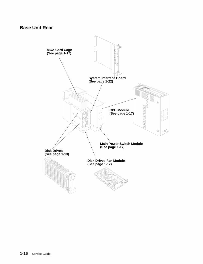
Base Unit Rear
Disk Drives(See page 1-13)
System Interface Board(See page 1-22)
CPU Module(See page 1-17)
Main Power Switch Module(See page 1-17)
Disk Drives Fan Module(See page 1-17)
MCA Card Cage(See page 1-17)
7013 J Series Unit Descriptions 1-17
Main Power Switch ModuleContains the switch for general AC power On and Off control, and the AC power cableconnector.
Micro Channel Adapters (MCA) Card Cage• The MCA card cage contains up to 6 adapters (optional) and one SCSI controller
(required)
Disk Drives Fan ModuleThis fan module, composed of two fans is installed only in units with two SCSI buses. It isused in both the base and expansion units to cool the system interface board(s) and thedisk drives placed in the left rear side.
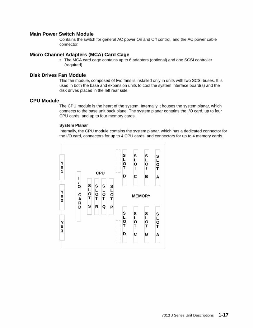
CPU ModuleThe CPU module is the heart of the system. Internally it houses the system planar, whichconnects to the base unit back plane. The system planar contains the I/O card, up to fourCPU cards, and up to four memory cards.
System PlanarInternally, the CPU module contains the system planar, which has a dedicated connector forthe I/O card, connectors for up to 4 CPU cards, and connectors for up to 4 memory cards.
I/O CARD
SLOT
D
SLOT
C
SLOT
B
SLOT
A
SLOT
D
SLOT
C
SLOT
B
SLOT
A
SLOT
S
SLOT
R
SLOT
Q
SLOT
P
CPU
MEMORY
Y01
Y02
Y03
1-18 Service Guide
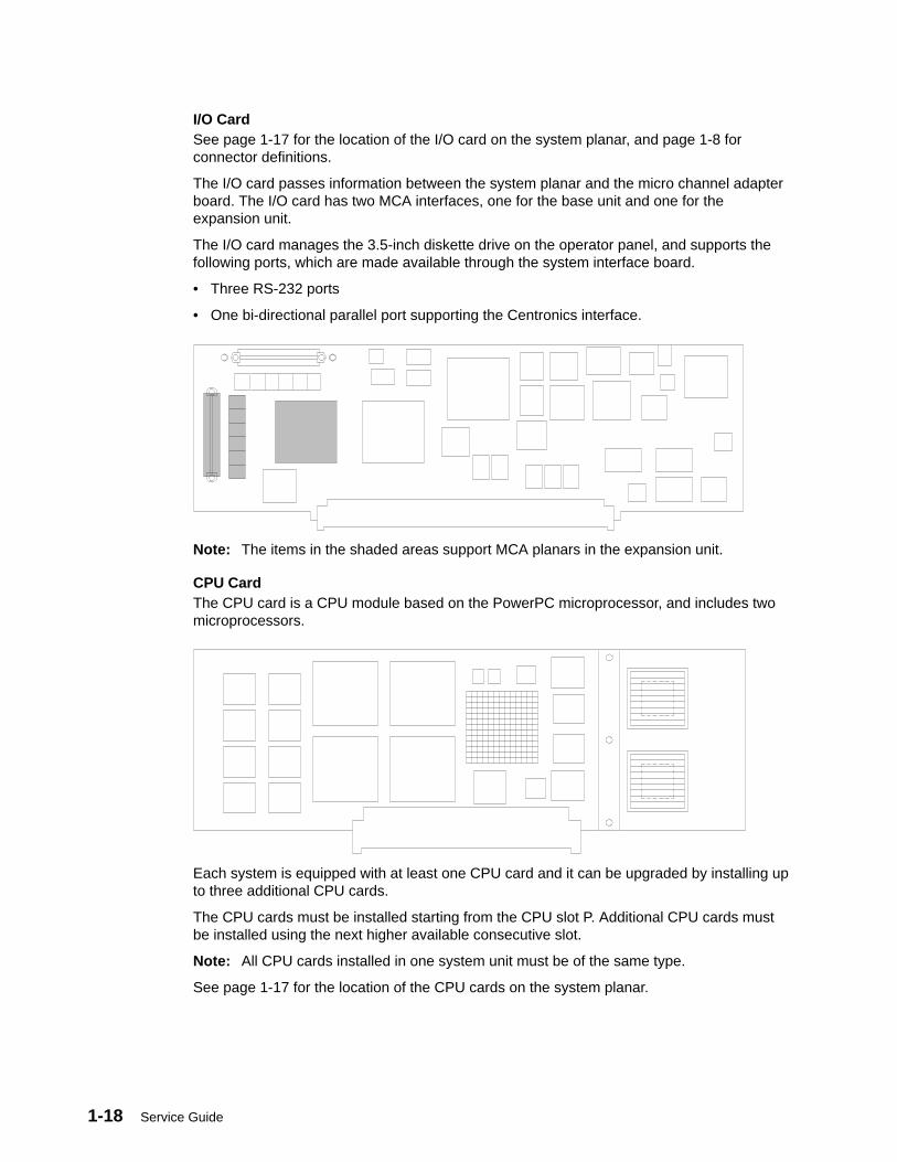
I/O CardSee page 1-17 for the location of the I/O card on the system planar, and page 1-8 forconnector definitions.
The I/O card passes information between the system planar and the micro channel adapterboard. The I/O card has two MCA interfaces, one for the base unit and one for theexpansion unit.
The I/O card manages the 3.5-inch diskette drive on the operator panel, and supports thefollowing ports, which are made available through the system interface board.
• Three RS-232 ports
• One bi-directional parallel port supporting the Centronics interface.
Note: The items in the shaded areas support MCA planars in the expansion unit.
CPU CardThe CPU card is a CPU module based on the PowerPC microprocessor, and includes twomicroprocessors.
Each system is equipped with at least one CPU card and it can be upgraded by installing upto three additional CPU cards.
The CPU cards must be installed starting from the CPU slot P. Additional CPU cards mustbe installed using the next higher available consecutive slot.
Note: All CPU cards installed in one system unit must be of the same type.
See page 1-17 for the location of the CPU cards on the system planar.
7013 J Series Unit Descriptions 1-19
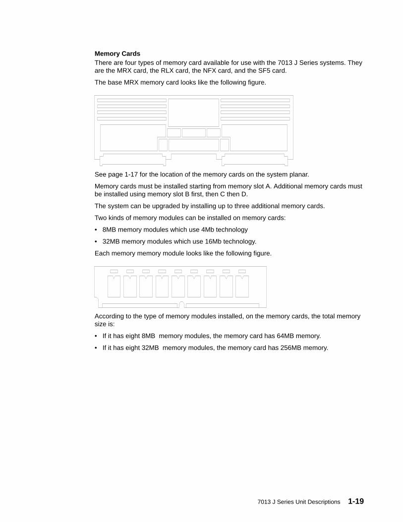
Memory CardsThere are four types of memory card available for use with the 7013 J Series systems. Theyare the MRX card, the RLX card, the NFX card, and the SF5 card.
The base MRX memory card looks like the following figure.
See page 1-17 for the location of the memory cards on the system planar.
Memory cards must be installed starting from memory slot A. Additional memory cards mustbe installed using memory slot B first, then C then D.
The system can be upgraded by installing up to three additional memory cards.
Two kinds of memory modules can be installed on memory cards:
• 8MB memory modules which use 4Mb technology
• 32MB memory modules which use 16Mb technology.
Each memory memory module looks like the following figure.
According to the type of memory modules installed, on the memory cards, the total memorysize is:
• If it has eight 8MB memory modules, the memory card has 64MB memory.
• If it has eight 32MB memory modules, the memory card has 256MB memory.
1-20 Service Guide
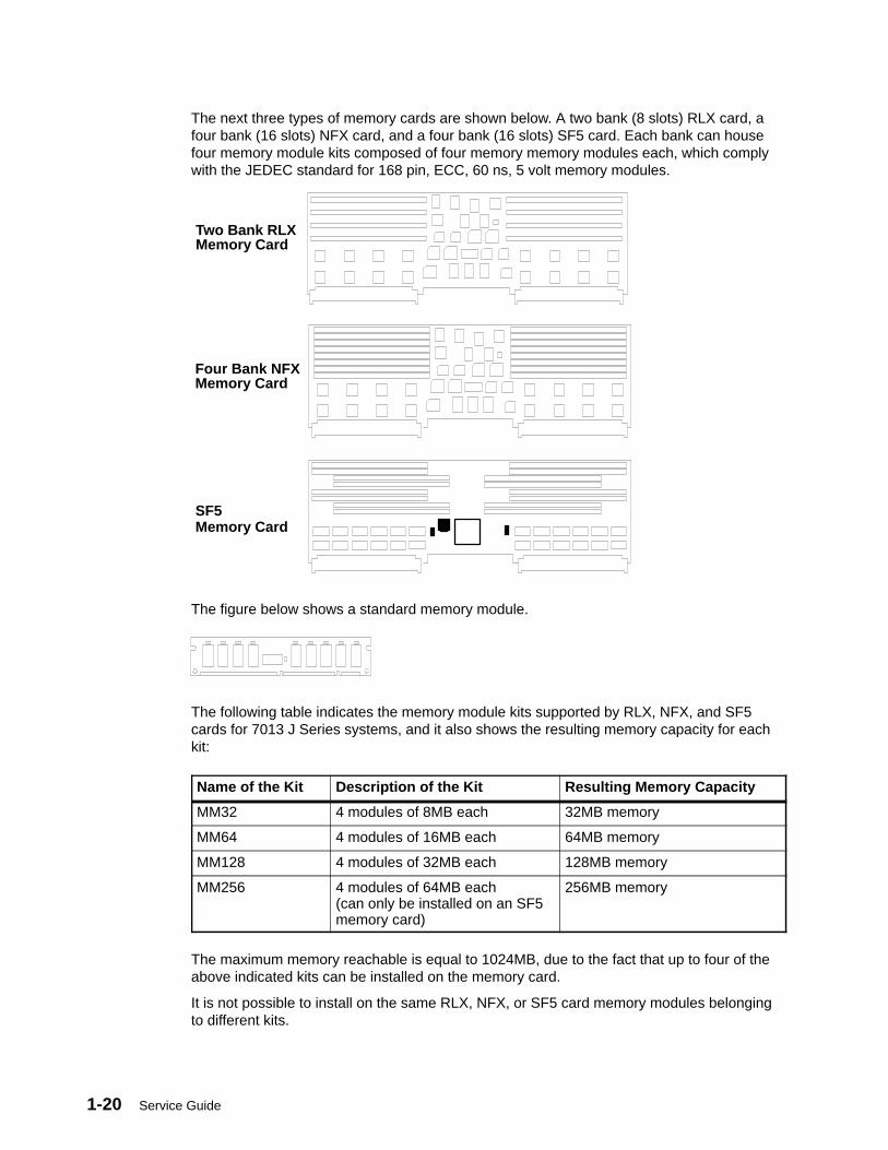
The next three types of memory cards are shown below. A two bank (8 slots) RLX card, afour bank (16 slots) NFX card, and a four bank (16 slots) SF5 card. Each bank can housefour memory module kits composed of four memory memory modules each, which complywith the JEDEC standard for 168 pin, ECC, 60 ns, 5 volt memory modules.
Two Bank RLXMemory Card
Four Bank NFXMemory Card
SF5Memory Card
The figure below shows a standard memory module.
The following table indicates the memory module kits supported by RLX, NFX, and SF5cards for 7013 J Series systems, and it also shows the resulting memory capacity for eachkit:
Name of the Kit Description of the Kit Resulting Memory Capacity
MM32 4 modules of 8MB each 32MB memory
MM64 4 modules of 16MB each 64MB memory
MM128 4 modules of 32MB each 128MB memory
MM256 4 modules of 64MB each(can only be installed on an SF5memory card)
256MB memory
The maximum memory reachable is equal to 1024MB, due to the fact that up to four of theabove indicated kits can be installed on the memory card.
It is not possible to install on the same RLX, NFX, or SF5 card memory modules belongingto different kits.
7013 J Series Unit Descriptions 1-21
According to both the size and the number of memory module kits installed on the RLX,NFX, or SF5 cards, these can be divided into the following models:
• NF64 board, based on 4M bit technology, which gives 64MB memory. It houses twoMM32 memory module kits.
• NF128 board, based on 4M bit technology, which gives 128MB memory. It houses twoMM64 memory module kits.
• NF256 board, based on 16M bit technology, which gives 256MB memory. It houses twoMM128 memory module kits.
• NF512 board, based on 16M bit technology, which gives 512MB memory. It houses fourMM128 memory module kits.
• NF1024 board, based on 16M bit technology, which gives 1024MB memory. It housesfour MM256 memory module kits.
Note: The maximum memory configuration yields a system with:
• 2048MB for J30 and J40
• 4096MB for J50.
1-22 Service Guide
System Interface BoardOne system interface board is required on both the base and expansion units. In addition, asecond system interface board is required on the expansion unit if any device is placed onthe B bus of the expansion unit. This is the only reason for the second system interfaceboard on the expansion unit, it is not involved in the power supply management.
The system interface board provides four functions:
Power Microcontroller The power microcontroller helps the BringupMicroprocessor (BUMP) to monitor each unitand its power supply, and to guarantee the unitscommunication.
Removable disks switch This function enables you to remove one ormore SCSI devices (disk drives and mediadevices) while the machine is still powered onand operational.
The system interface board controls the powerdomains for all of the internal SCSI devices. Theremovable disks switch (RDS) removes both the+5 and the +12 volts from the SCSI devicesselected by the RDS function in SMIT.
System basic lines physical interface It checks the asynchronous lines drivers andreceivers (S1, S2, S3) and is the asynchronouslines bulkhead.
The system interface board also is the bulkheadfor the parallel port. The signals come from theI/O card through the unit back plane, and reachthe dedicated connector on the system interfaceboard.
SCSI bulkhead The system interface board is a bulkhead for thefirst (A) and second (B) SCSI buses, forterminator or the second external SCSIcontroller connection (dual initiator). The signalscome from the SCSI controller through the unitback plane, and reach the dedicated connectoron the system interface board.
Attention: The back plane and system interface board EEPROMs contain the SYSID of thesystem. When one of the two components is to be replaced (for example the back plane),the SYSID information will be copied from the system interface board EEPROM into theback plane EEPROM when you start the system.
To avoid loosing this information, it is not possible to replace both components at the sametime.When both components are to be replaced, proceed as follows:
1. First substitute the system interface board and start up the system: the SYSIDinformation will be copied from back plane EEPROM to the system interface boardEEPROM.
2. Substitute the back plane and start up the system: the SYSID information will be copiedfrom the system interface board EEPROM to the back plane EEPROM.
7013 J Series Unit Descriptions 1-23
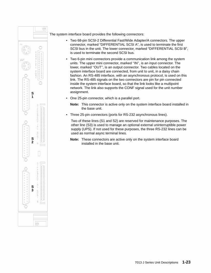
The system interface board provides the following connectors:
• Two 68-pin SCSI-2 Differential Fast/Wide Adapter/A connectors. The upperconnector, marked “DIFFERENTIAL SCSI A”, is used to terminate the firstSCSI bus in the unit. The lower connector, marked “DIFFERENTIAL SCSI B”,is used to terminate the second SCSI bus.
• Two 6-pin mini connectors provide a communication link among the systemunits. The upper mini connector, marked ‘‘IN’’, is an input connector. Thelower, marked ‘‘OUT’’, is an output connector. Two cables located on thesystem interface board are connected, from unit to unit, in a daisy chainfashion. An RS-485 interface, with an asynchronous protocol, is used on thislink. The RS-485 signals on the two connectors are pin for pin connectedinside the system interface board, so that the link looks like a multipointnetwork. The link also supports the CONF signal used for the unit numberassignment.
• One 25-pin connector, which is a parallel port.
Note: This connector is active only on the system interface board installed inthe base unit.
• Three 25-pin connectors (ports for RS-232 asynchronous lines).
Two of these lines (S1 and S2) are reserved for maintenance purposes. Theother line (S3) is used to manage an optional external uninterruptible powersupply (UPS). If not used for these purposes, the three RS-232 lines can beused as normal async terminal lines.
Note: These connectors are active only on the system interface boardinstalled in the base unit.
S1
S2
S3
1-24 Service Guide
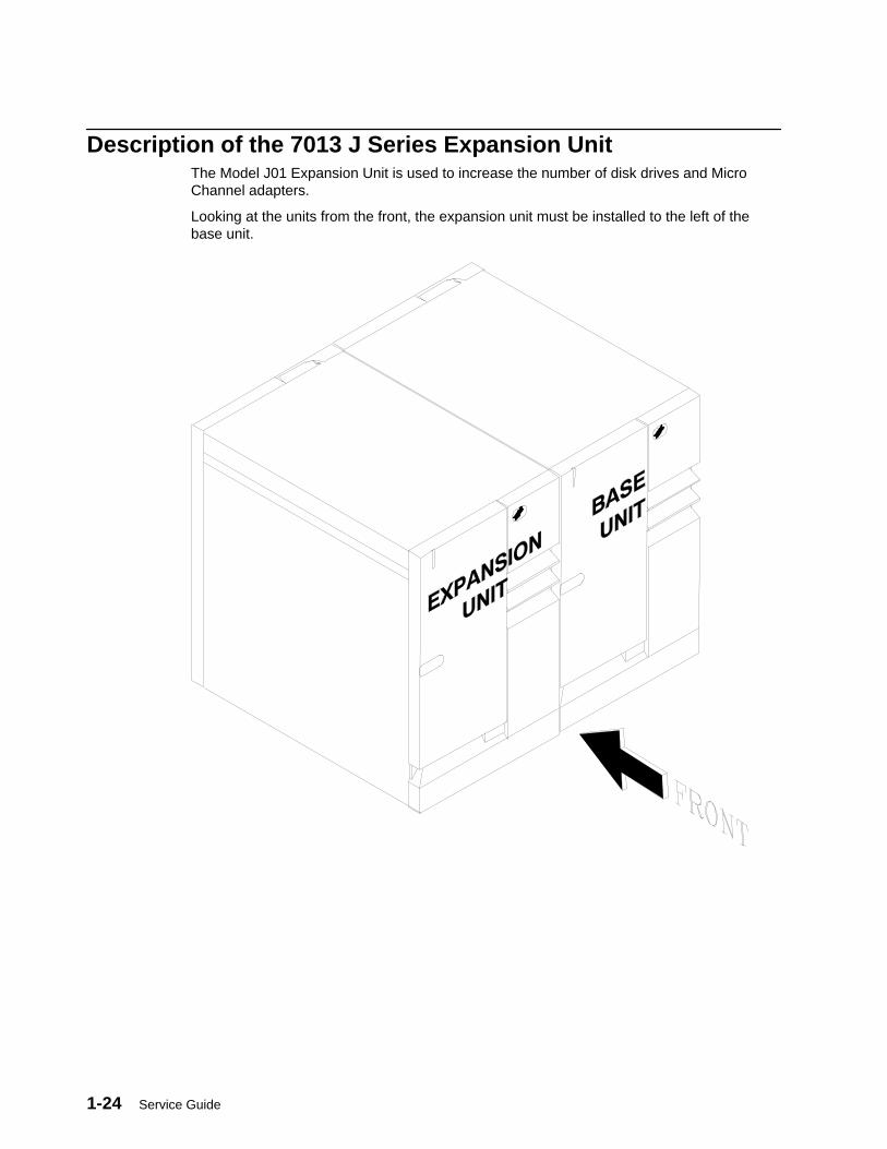
Description of the 7013 J Series Expansion UnitThe Model J01 Expansion Unit is used to increase the number of disk drives and MicroChannel adapters.
Looking at the units from the front, the expansion unit must be installed to the left of thebase unit.
7013 J Series Unit Descriptions 1-25
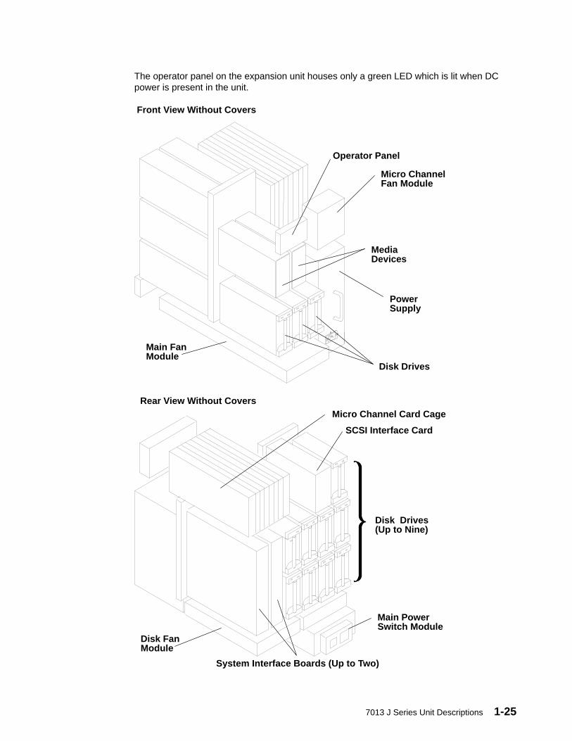
The operator panel on the expansion unit houses only a green LED which is lit when DCpower is present in the unit.
Main FanModule
Disk Drives
PowerSupply
MediaDevices
Micro ChannelFan Module
Front View Without Covers
Operator Panel
Disk Drives(Up to Nine)
Micro Channel Card Cage
System Interface Boards (Up to Two)
SCSI Interface Card
Main PowerSwitch Module
Disk FanModule
Rear View Without Covers

1-26 Service Guide
Expansion Unit SCSI BusesThe expansion unit is equipped with one or two active SCSI buses.
Each SCSI bus in the expansion unit is driven by a SCSI-2 Differential Fast/Wide Adapter/Acontroller connected to the SCSI interface card.
Each SCSI bus is terminated with SCSI terminators installed in the designated connector onthe required system interface board.
A dedicated SCSI interface board supports the SCSI input from the controller to the backplane.
The two SCSI buses of the expansion unit are two different entities which cannot beconnected in series in the unit.
If the expansion unit has more than seven SCSI devices, it needs a second systeminterface board to support the additional devices.
Location of disk drives in the Expansion UnitThe letter of each drive indicates which SCSI bus controls the drive. The number is theSCSI address of the drive.
Expansion Unit Rear View
B0 A0
A4 A5 A6
A1 B3 A2
B1 B6 B5
Expansion Unit Front View
A3
B2
B4
SCSI TerminatorsEach internal SCSI bus used in the expansion unit (that means a SCSI bus to which at leastone SCSI disk drive or media device is connected), must be terminated with a SCSIterminator. This terminator must be installed on the required system interface board,observing the following guidelines:
• The first SCSI bus (A) must be terminated with a SCSI terminator installed on the‘‘DIFFERENTIAL SCSI A’’ connector of the required system interface board.
• The second SCSI bus (B) must be terminated with a SCSI terminator installed on the‘‘DIFFERENTIAL SCSI B’’ connector of the required system interface board.
• The connectors on the system interface board are for terminators only. No externaldevices can be attached to these connectors.
7013 J Series Unit Descriptions 1-27
Micro Channel Adapter (MCA) Card CageThe MCA card cage is in the rear of the expansion unit. It can house up to eight adaptercards.
An MCA planar is located at the bottom of the MCA card cage. This planar is called theMCA Expansion Planar (MPe) on the expansion unit.
When an MCA slot is not occupied, a dummy plate must be installed for EMC shielding andto protect it from dust or debris. When an adapter is to be installed, the dummy plate mustbe removed.
On the expansion unit, the eight connectors can be used to install:
• One optional SCSI-2 Differential Fast/Wide Adapter/A controller in slot 8
• Up to seven supported MCA adapters, which can be installed in any of the remainingslots.

1-28 Service Guide
SCSI ControllersThe slots dedicated to the SCSI controllers in the expansion unit are shown in the followingfigure.
Second SCSI Controller in Slot 7 (optional)
First SCSI Controller in Slot 8 (optional)
If more than two SCSI controllers are needed in the expansion unit, these can be installed inany free slot.
If no SCSI controllers are installed in the expansion unit MCA card cage, the dedicated slotscan be used to install any other MCA adapters.
7013 J Series Unit Descriptions 1-29
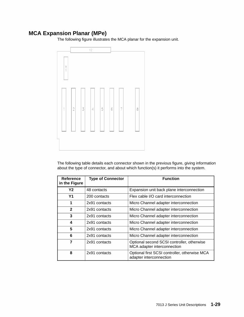
MCA Expansion Planar (MPe)The following figure illustrates the MCA planar for the expansion unit.
The following table details each connector shown in the previous figure, giving informationabout the type of connector, and about which function(s) it performs into the system.
Referencein the Figure
Type of Connector Function
Y2 48 contacts Expansion unit back plane interconnection
Y1 200 contacts Flex cable I/O card interconnection
1 2x91 contacts Micro Channel adapter interconnection
2 2x91 contacts Micro Channel adapter interconnection
3 2x91 contacts Micro Channel adapter interconnection
4 2x91 contacts Micro Channel adapter interconnection
5 2x91 contacts Micro Channel adapter interconnection
6 2x91 contacts Micro Channel adapter interconnection
7 2x91 contacts Optional second SCSI controller, otherwiseMCA adapter interconnection
8 2x91 contacts Optional first SCSI controller, otherwise MCAadapter interconnection
1-30 Service Guide
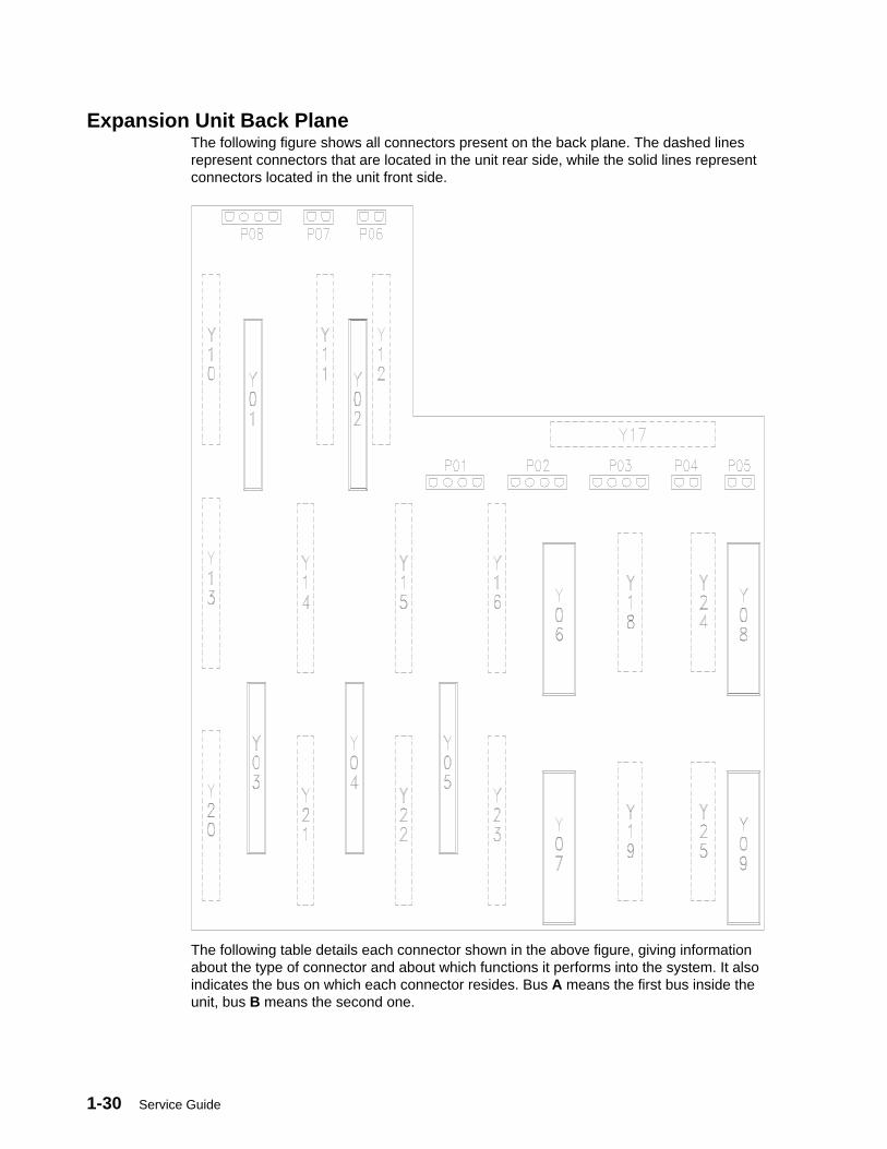
Expansion Unit Back PlaneThe following figure shows all connectors present on the back plane. The dashed linesrepresent connectors that are located in the unit rear side, while the solid lines representconnectors located in the unit front side.
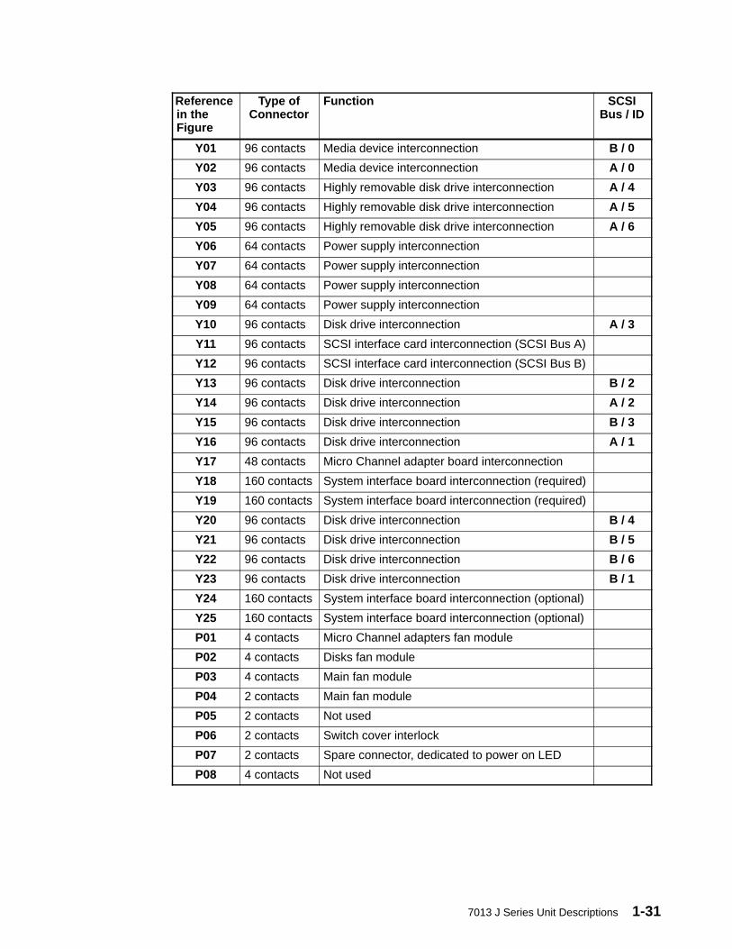
The following table details each connector shown in the above figure, giving informationabout the type of connector and about which functions it performs into the system. It alsoindicates the bus on which each connector resides. Bus A means the first bus inside theunit, bus B means the second one.
7013 J Series Unit Descriptions 1-31
Referencein theFigure
Type ofConnector
Function SCSIBus / ID
Y01 96 contacts Media device interconnection B / 0
Y02 96 contacts Media device interconnection A / 0
Y03 96 contacts Highly removable disk drive interconnection A / 4
Y04 96 contacts Highly removable disk drive interconnection A / 5
Y05 96 contacts Highly removable disk drive interconnection A / 6
Y06 64 contacts Power supply interconnection
Y07 64 contacts Power supply interconnection
Y08 64 contacts Power supply interconnection
Y09 64 contacts Power supply interconnection
Y10 96 contacts Disk drive interconnection A / 3
Y11 96 contacts SCSI interface card interconnection (SCSI Bus A)
Y12 96 contacts SCSI interface card interconnection (SCSI Bus B)
Y13 96 contacts Disk drive interconnection B / 2
Y14 96 contacts Disk drive interconnection A / 2
Y15 96 contacts Disk drive interconnection B / 3
Y16 96 contacts Disk drive interconnection A / 1
Y17 48 contacts Micro Channel adapter board interconnection
Y18 160 contacts System interface board interconnection (required)
Y19 160 contacts System interface board interconnection (required)
Y20 96 contacts Disk drive interconnection B / 4
Y21 96 contacts Disk drive interconnection B / 5
Y22 96 contacts Disk drive interconnection B / 6
Y23 96 contacts Disk drive interconnection B / 1
Y24 160 contacts System interface board interconnection (optional)
Y25 160 contacts System interface board interconnection (optional)
P01 4 contacts Micro Channel adapters fan module
P02 4 contacts Disks fan module
P03 4 contacts Main fan module
P04 2 contacts Main fan module
P05 2 contacts Not used
P06 2 contacts Switch cover interlock
P07 2 contacts Spare connector, dedicated to power on LED
P08 4 contacts Not used
1-32 Service Guide
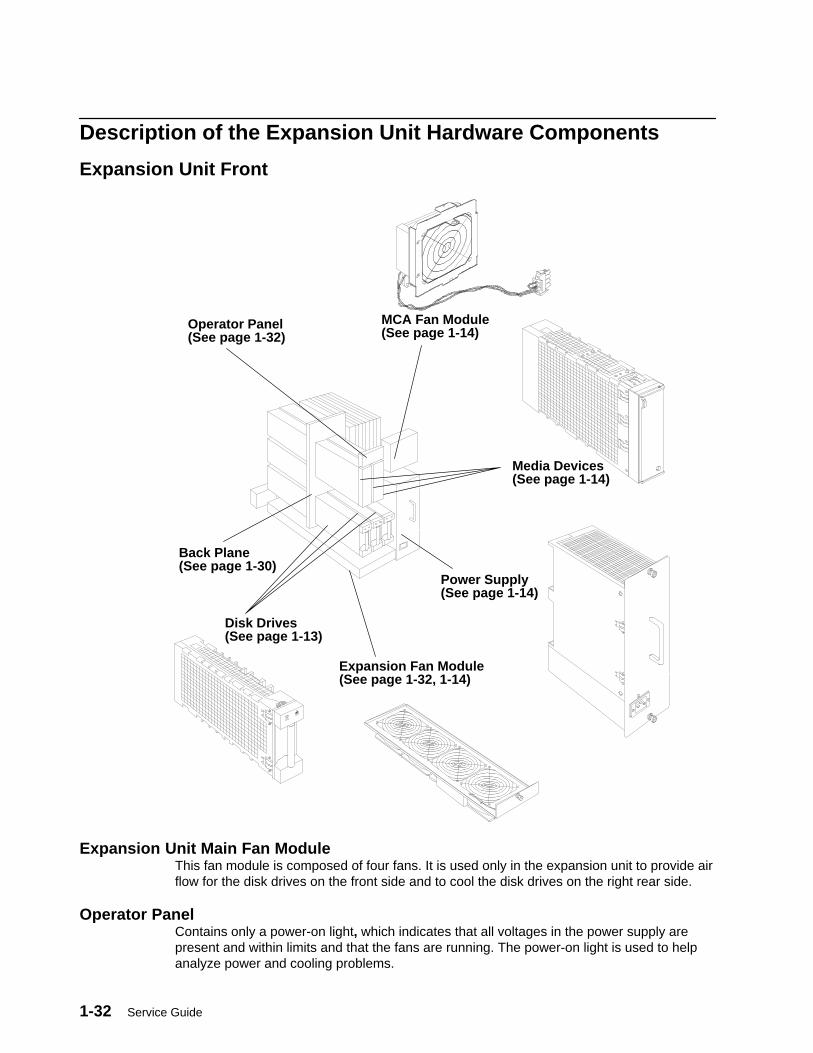
Description of the Expansion Unit Hardware Components
Expansion Unit Front
Power Supply(See page 1-14)
Media Devices(See page 1-14)
Back Plane(See page 1-30)
Disk Drives(See page 1-13)
MCA Fan Module(See page 1-14)
Expansion Fan Module(See page 1-32, 1-14)
Operator Panel(See page 1-32)
Expansion Unit Main Fan ModuleThis fan module is composed of four fans. It is used only in the expansion unit to provide airflow for the disk drives on the front side and to cool the disk drives on the right rear side.
Operator PanelContains only a power-on light, which indicates that all voltages in the power supply arepresent and within limits and that the fans are running. The power-on light is used to helpanalyze power and cooling problems.

7013 J Series Unit Descriptions 1-33
Expansion Unit Rear
Disk Drives(See page 1-13)
Main Power Switch Module(See page 1-17)
Disk Drives Fan Module(See page 1-17)
(Optional) and (Required)System Interface Boards(See pages 1-34)
SCSI Interface Card(See page 1-34)
MCA Card Cage(See page 1-34)
1-34 Service Guide
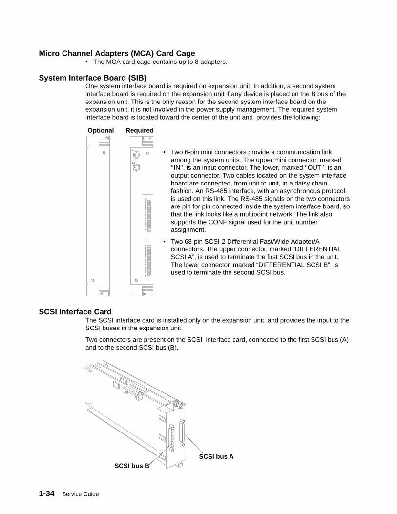
Micro Channel Adapters (MCA) Card Cage• The MCA card cage contains up to 8 adapters.
System Interface Board (SIB)One system interface board is required on expansion unit. In addition, a second systeminterface board is required on the expansion unit if any device is placed on the B bus of theexpansion unit. This is the only reason for the second system interface board on theexpansion unit, it is not involved in the power supply management. The required systeminterface board is located toward the center of the unit and provides the following:
• Two 6-pin mini connectors provide a communication linkamong the system units. The upper mini connector, marked‘‘IN’’, is an input connector. The lower, marked ‘‘OUT’’, is anoutput connector. Two cables located on the system interfaceboard are connected, from unit to unit, in a daisy chainfashion. An RS-485 interface, with an asynchronous protocol,is used on this link. The RS-485 signals on the two connectorsare pin for pin connected inside the system interface board, sothat the link looks like a multipoint network. The link alsosupports the CONF signal used for the unit numberassignment.
• Two 68-pin SCSI-2 Differential Fast/Wide Adapter/Aconnectors. The upper connector, marked “DIFFERENTIALSCSI A”, is used to terminate the first SCSI bus in the unit.The lower connector, marked “DIFFERENTIAL SCSI B”, isused to terminate the second SCSI bus.
SCSI Interface CardThe SCSI interface card is installed only on the expansion unit, and provides the input to theSCSI buses in the expansion unit.
Two connectors are present on the SCSI interface card, connected to the first SCSI bus (A)and to the second SCSI bus (B).
SCSI bus ASCSI bus B
RequiredOptional
7013 J Series Unit Descriptions 1-35
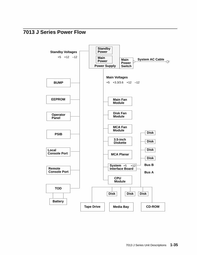
7013 J Series Power Flow
StandbyPower
MainPower Main
PowerSwitch
Standby Voltages
Power Supply
Main Voltages
System AC Cable
CPUModule
Disk
MCA Planar
SystemInterface Board
MCA FanModule
3.5-inchDiskette
Main FanModule
Disk FanModule
LocalConsole Port
TOD
OperatorPanel
PSIB
BUMP
EEPROM
Media Bay CD-ROM
Disk Disk
RemoteConsole Port
Battery
+5 +3.3/3.6 +12 –12
+5 +12 –12
+5 +12
Tape Drive
Disk
Disk
Disk
Disk
Bus A
Bus B
1-36 Service Guide
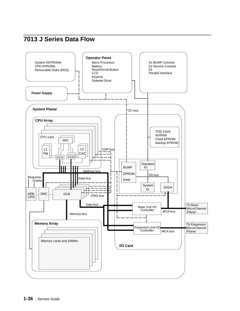
7013 J Series Data Flow
CPU card60X
L2Tag
L2CAC
Address bus
Data bus
SMC DCB
Memory bus
BUMPStandard
IO
SystemIO
MCA bus
MCA bus
Memory cards and DIMMs
System Planar
I/O Card
CPU Array
Memory ArrayExpansion Unit I/O
Controller
JTAG bus
COP bus
SSGA
I2C bus
EPROM
RAM
S2 Service ConsoleS3
S1 BUMP ConsoleMicro ProcessorBatteryReset/Scroll ButtonLCDKeylock
System EEPROMsVPD EPROMs
Operator Panel
Diskette Drive
Power Supply
CCA CCD
Base Unit I/OController
SS bus
To BaseMicroChannelPlanar
To ExpansionMicroChannelPlanar
Parallel Interface
Data bus
TOD ClockNVRAMFlash EPROMBackup EPROM
Removable Disks (RDS)
ARB(J50)
RequestsGrants

7013 J Series Unit Descriptions 1-37
1
8
23
45
6
7
1
23
45
6
7
Base Unit MCA
Expansion Unit
Card Cage
MCA Card Cage
Base MicroChannel Planar
Expansion MicroChannel Planar
Xvr
Xvr
Misc
Misc

1-38 Service Guide
Specifications
DimensionsHeight 610 mm (24.02 inches)Depth 750 mm (29.53 inches)Width 360 mm (14.17 inches)
Weight
Base UnitMinimum 67 KgMaximum 84 Kg
Expansion UnitMinimum 67 KgMaximum 92 Kg
Relative Humidity
Operating limitsRelative humidity: 20 to 80 percent, non-condensing (magnetic tapes may not work below20 percent)
Gradient: 10 percent/h
Max wet bulb temperature: +24 C degrees
Moisture content: 0.019 Kg water/Kg dry air
Non-operating limitsRelative humidity: 5 to 95 percent, non-condensing
Gradient: 30 percent/h
Max wet bulb temperature: +28 C degrees
Moisture content: 0.024 Kg water/Kg dry air
Environment Temperature
Operating limitsDry bulb temperature: +10 to +32 C degrees
Gradient: 10 C degrees/h
Non-operating limitsDry bulb temperature: +5 to +50 C degrees
Gradient: 25 C degrees/h
Input PowerInternational standard: IEC 555-2
The following values have been calculated considering the maximum power load.
Base Unit 1.2 kVA – 1.2KWExpansion Unit 0.7 kVA – 0.7KW
7013 J Series Unit Descriptions 1-39
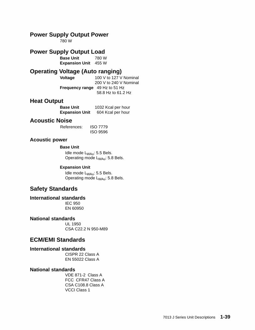
Power Supply Output Power780 W
Power Supply Output LoadBase Unit 780 WExpansion Unit 455 W
Operating Voltage (Auto ranging)Voltage 100 V to 127 V Nominal
200 V to 240 V NominalFrequency range 49 Hz to 51 Hz
58.8 Hz to 61.2 Hz
Heat OutputBase Unit 1032 Kcal per hourExpansion Unit 604 Kcal per hour
Acoustic NoiseReferences: ISO 7779
ISO 9596
Acoustic powerBase Unit
Idle mode LWAu: 5.5 Bels.Operating mode LWAu: 5.8 Bels.
Expansion UnitIdle mode LWAu: 5.5 Bels.Operating mode LWAu: 5.8 Bels.
Safety Standards
International standardsIEC 950EN 60950
National standardsUL 1950CSA C22.2 N 950-M89
ECM/EMI Standards
International standardsCISPR 22 Class AEN 55022 Class A
National standardsVDE 871-2 Class AFCC CFR47 Class ACSA C108.8 Class AVCCI Class 1
1-40 Service Guide
Power CablesTo avoid electrical shock, a power cable with a grounded attachment plug is provided. Useonly properly grounded outlets.
Power cables used in the U.S.A. and Canada are listed by Underwriter’s Laboratories (UL)and certified by the Canadian Standards Association (CSA). These power cords consist of:
• Electrical cables, Type SVT or SJT.
• Attachment plugs complying with National Electrical Manufacturers Association (NEMA)5-15P. That is:
“For 115 V operation, use a UL-listed cable set consisting of a minimum 16 AWG, TypeSVT or SJT three-conductor cord a maximum of 15 feet in length and a parallel blade,grounding type attachment plug rated at 15 A, 125 V.”
“For 230 V operation in the U.S.A. use a UL-listed cable set consisting of a minimum 16AWG, Type SVT or SJT three-conductor cable a maximum of 15 feet in length, and atandem blade, grounding type attachment plug rated at 15 A, 250 V.”
• Appliance couplers complying with International Electrotechnical Commission (IEC)Standard 320, Sheet C13.
Power cables used in other countries consist of the following:
• Electrical cables, type HD21.
• Attachment plugs approved by the appropriate testing organization for the specificcountries where they are used.
“For units set at 230 V (outside U.S.A.): use a cable set consisting of a minimum 16AWG cable and grounding type attachment plug rated 15 A, 250 V. The cable set shouldhave the appropriate safety approvals for the country in which the equipment will beinstalled and should be marked ‘HAR’.”
Refer to the Parts Information section of this publication to find the power cables that areavailable.
7013 J Series Unit Descriptions 1-41
Checking Customer OutletsNote: For a translation of the following notices, see System Unit Safety Information, Order
Number SA23-2652.
CAUTION:Do not touch the receptacle or the receptacle faceplate with anything other than yourtest probes before you have met the requirement in step 8.
1. Have the customer locate and turn off the branch circuit CB (circuit breaker). (Attach tagS229-0237, which reads “Do Not Operate.”)
Note: All measurements are made with the receptacle faceplate in its normal installedposition.
2. Some receptacles are enclosed in metal housings. On receptacles of this type, performthe following steps:
a. Check for less than 1 volt from the receptacle case to any grounded metal structure inthe building, such as a raised floor metal structure, water pipe, building steel, orsimilar structure.
b. Check for less than 1 volt from receptacle ground pin to a grounded point in thebuilding.
Note: If the receptacle case or faceplate is painted, be sure the probe tip penetrates thepaint and makes good electrical contact with the metal.
c. Check the resistance from ground pin of the receptacle to the receptacle case. Checkresistance from ground pin to building ground. The reading should be less than 1.0ohm, which indicates the presence of a continuous grounding conductor.
3. If any of the three checks made in step 2 are not correct, ask the customer to remove thepower from the branch circuit and make the wiring corrections; then check the receptacleagain.
Note: Do not use the digital multimeter to measure grounding resistance.
4. Check for infinite resistance between the ground pin of the receptacle and each of thephase pins. This is a check for a wiring short to ground or a wiring reversal.
5. Check for infinite resistance between phase pins. This is a check for a wiring short.
CAUTION:If the reading is other than infinity, do not proceed. Have the customer makenecessary wiring corrections before continuing. Do not turn on the branch circuit CBuntil all the above steps are satisfactorily completed.
6. Have the customer turn on the branch circuit CB. Measure for appropriate voltagesbetween phases. If no voltage is present on the receptacle case or grounded pin, thereceptacle is safe to touch.
7. With an appropriate meter, verify that the voltage at the outlet is correct.
8. Verify that the grounding impedance is correct by using the ECOS 1020, 1023, B7106,C7106, or an appropriately approved ground impedance tester.
Note: Do not use the 120-volt convenience outlets inside a machine to power the tester.

1-42 Service Guide
Service Inspection GuidePerform a service inspection on the system when:
• The system is inspected for a maintenance agreement.
• Service is requested and service has not recently been performed.
• An alterations and attachments review is performed.
• Changes have been made to the equipment that may affect the safe operation of theequipment.
• External devices that have their own power cable are attached.
If the inspection indicates an unacceptable safety condition, the condition must be correctedbefore the machine is serviced.
Note: The correction of any unsafe condition is the responsibility of the owner of thesystem.
Perform the following checks:
1. Check the covers for sharp edges and for damage or alterations that expose the internalparts of the system unit.
2. Check the covers for proper fit to the system unit. They should be in place and secure.
3. Gently rock the system unit from side to side to determine if it is steady.
4. Set the power switch of the system unit to Off.
5. Remove the covers.
6. Check for alterations or attachments. If there are any, check for obvious safety hazardssuch as broken wires, sharp edges, or broken insulation.
7. Check the internal cables for damage.
8. Check for dirt, water, and any other contamination within the system unit.
9. Check for dirt in fans.
10. Check the voltage label on the back of the system unit to ensure that it matches thevoltage at the outlet.
11. Check the external power cable for damage.
12. With the external power cable connected to the system unit, check for 0.1 ohm or lessresistance between the ground lug on the external power cable plug and the metalframe.
13. Install the covers.
14. Check each external device that has its own power cable:
a. For damage to the power cord.b. For the correct grounded power cable.c. With the external power cable connected to the device, check for 0.1 ohm or less
resistance between the ground lug on the external power cable plug and the metalframe of the device.
15. Check error log for recent activity.
The “Installation Checkout” that follows in new to this book. It has been taken from chapter 5 of 7012 GSeries Service Guide, order number SA23-2741

7013 J Series Unit Descriptions 1-43
Installation Checkout
Installation Checkout ProcedureThe installation checkout procedure is used to check out the system after initial installationor after a system upgrading kit is installed. NO TAGGo to Step 1.
Notes:
1. The following procedure can be followed only if the AUTOSERVICEIPL flag (thisflag can be set in the STAND BY menu) is set to 1.
2. For details about the MAP’s mentioned in this section, please refer to theCommon Diagnostic and Service Guide delivered with your system.
Step 1. Doing a Visual CheckDo the following for initial installation and after altering the system:
1. Be sure the system unit power ON/OFF button is set to Off.
2. Be sure the power switches on all of the attached devices are set to Off.
3. Visually check the system unit and attached devices for:
• All power cables are securely attached to the system unit or devices• All signal cables are connected at both ends• All power cables are plugged into the customer’s outlet• All covers are installed and the fan openings are not obstructed• All ribbons, guides, and other attachments are in place.
4. Go to Step 2.
Step 2. Checking the TTY Terminal AttributesChecking the TTY Terminal Attributes usually needs to be accomplished only during theinitial installation.
If you have trouble selecting the console display and you are using an attached terminal,check the TTY Terminal Attributes again.
When you run the diagnostic programs from an attached TTY terminal, the attributes for theterminal must be set to match the defaults of the diagnostic programs. The TTY terminalmust be attached to the S1 or S2 port on the system unit.
Are you going to run this procedure on an attached TTY terminal?
NO Go to Step 3.
YES Go to “Running the Diagnostic Programs from a TTY Terminal” in Using OnLine Diagnostics in Chapter 7 of Common Diagnostic and Service Guide,and check the terminal attributes. Return to Step 3 when you finishchecking the attributes.
1-44 Service Guide
Step 3. Loading the DiagnosticsThe diagnostics can be run from a CD ROM disk, from a locally attached disk, or from aserver if Version 4.1 (or higher) of the operating system is installed on the system.
If you are not sure whether Version 4.1 (or higher) of the operating system is installed, youcan check by setting the mode switch to the Service position and turning the system unit on.If the system stops with two or more numbers between 221 and 296 alternating in theLCD display, Version 4.1 (or higher) of the operating system is not installed.
If Version 4.1 (or higher) of the operating system is installed, the diagnostic programs shouldload from a locally attached disk or from a server.
If Version 4.1 (or higher) of the operating system is not used, the diagnostics can be loadedfrom the diskettes or from the diagnostic CD ROM disk.
The following procedure will attempt to load the diagnostics from a disk or from a server. Ifthey cannot be loaded from a disk or server, the diagnostic CD ROM disk will be used toload and run the checkout.
1. Set the mode switch to the Service position.
2. Set the power switches on all of the attached devices to On.
3. Set the power switch on the system unit to On.
4. Watch the operator panel LCD display.
If the system stops with two or more numbers between 221 and 296 alternating in theLCD display, Version 4.1 (or higher) of the operating system is not installed. Do thefollowing:
a. Insert the first diagnostic diskette in the diskette drive, or insert the diagnostic CD ROM disk into the CD ROM drive.
Note: For more information on using diagnostic diskettes, please refer to the ”ServiceHints” section in this manual.
b. When c07 displays, insert the next diskette until the diagnostics are loaded.If c31 displays, follow the displayed instructions to select the console display.
If the system stops for at least three minutes with a steady number or a flashing 888displayed in the LCD display, a problem was detected during IPL of the diagnostics.Check for loose cables or cards. If you do not find a problem, go to MAP 0020.
5. When the diagnostic programs load correctly the DIAGNOSTIC OPERATINGINSTRUCTIONS display.
Did the DIAGNOSTIC OPERATING INSTRUCTIONS display?
NO Go to MAP 0020.
YES Go to Step 4.

7013 J Series Unit Descriptions 1-45
Step 4. Checking for the Correct ResourcesUse the “Display or Change Configuration or VPD” service aid to check the resources thatare present (memory cards, SCSI devices, adapters, diskette drives, disk drives, and inputdevices).
Note: If the terminal type has not been defined, it will need to be defined before you canselect the service aids. Use the Initialize Terminal option on theFUNCTION SELECTION menu to define the terminal.
If the Dials and LPFK are attached to serial ports S1 or S2, they will not be listed bythe service aid unless they have been configured by the user. Refer to operatingsystem documentation to configure these devices.
Were all the resources listed by the service aid?
NO Check for loose cables or cards. If you do not find a problem, go to MAP0020.
YES Go to Step 5.
Step 5. Checking the HardwareIf you are running from disk, the system can be checked by running the System Exerciser orby running diagnostics.
To run the System Exerciser:
1. Select System Exerciser from the Function Selection Menu .
2. Follow the on-screen instructions.
To run diagnostics:
1. Select Advanced Diagnostics on the FUNCTION SELECTION menu.
2. Select System Verification on the DIAGNOSTIC MODE SELECTION menu.
All resources can be checked out by selecting System Checkout on the ADVANCEDDIAGNOSTIC SELECTION menu, or you can select each resource individually.
3. Check each resource.
Did all of resources check out good?
NO Record the SRN; then go to MAP 0010.
YES Go to Step 6.
1-46 Service Guide
Step 6. Completing the InstallationSome of the following steps only apply to an initial installation. These steps are provided asreminders in completing the installation or finishing a system upgrading activity.
1. If present, remove the CD-ROM diagnostic disk from the appropriate drive, and store it inthe binder with the operator guides.
2. Set the mode switch to Secure.
3. Give the keys to the customer and explain the importance of keeping the reorder tag forthe keys in a safe place.
4. File a copy of the following items in the Account Management Planning Guide, formnumber Z-ZZ9–0417:
• Cable Planning Charts• SCSI Address Record from the Installation and Service Guide• Machine History Card for each system unit and device.
5. Microcode must be installed during system installation or after the operating system isinstalled. If the system is using Version 4.1 (or higher) of the operating system, allmicrocode is preinstalled on the boot disk for all adapters and devices that were shippedwith the system.
Microcode is shipped on microcode diskettes, option diskettes and on the boot disk. Forthe operating system, runtime microcode maintenance can be selected from the SMITINSTALLATION AND MAINTENANCE MENU or from the Diagnostic Service Aid.adfutil –m (command and flag) is normally used to install microcode shipped on optiondiskettes.
If the system is using another type of operating system, that operating system shouldinclude microcode installation instructions.
If you have the X.25 Interface Co-Processor or the 5080 Attachment Adapter, themicrocode for them is normally not shipped with the operating system. The microcode forthese adapters must be installed before the adapters can be used. The 5080 AttachmentAdapter Microcode is shipped on a microcode diskette. The X.25 Interface Co-Processormicrocode is shipped on an option diskette.
6. Contact the person that is going to install the software or turn the system to the customer.
If needed, go to the operating system Installation Kit to install and configure the operatingsystem.
Using SystemGuard 2-1
Chapter 2. Using SystemGuard
This chapter introduces the SystemGuard service processor which is included in allSymmetric Multiprocessor models.
IntroductionSMP servers include a service processor, called SystemGuard, as a standard feature.
SystemGuard continually monitors the hardware as well as the operating system. If, forinstance, a CPU fails, the system detects this, reboots itself automatically and runs thebuilt-in diagnostics on the hardware. If the CPU is detected as bad during the initial programload (IPL) or reIPL, the CPU is disabled. Likewise, if memory is detected as bad during IPLor reIPL, it is disabled.
SystemGuard allows diagnostics and maintenance to be performed either locally orremotely. The SystemGuard processor makes it possible for these remote systems to bemanaged from a central location. SMP servers can even be set up to automatically call aService Center if they fail to boot successfully.
The main features of the SystemGuard are:
• Initialization process flow management
• Local as well as remote control of the system (turning power on or off, diagnostics,reconfiguration, maintenance)
• Console mirroring to make remote actions visible and controllable by the customer
• Dial-out to a support center in case of system boot failure
• Run-Time surveillance
2-2 Service Guide
SystemGuard PowerSystemGuard has its own DC power boundary. This means that even if the system power isoff (power button of the system in the off position), SystemGuard is still powered on, as longas the unit is still plugged into an outlet and the main power switch on the back of thesystem unit is on. This allows control of the system even though the system is down. Theonly way to turn off the SystemGuard power is to turn off the main power switch at the backof the system unit or unplug the power cord.
A more detailed description of the system power states can be found in “Appendix F. SystemPower States.”
SystemGuard ComponentsSystemGuard introduces new hardware and firmware components.
• a microprocessor called the Bring-Up MicroProcessor (BUMP)• a Flash EEPROM• a Backup EPROM that enables the system to boot in case of a Flash EEPROM failure.
Part of the SystemGuard firmware is stored in the BUMP EPROM; part is in the FlashEEPROM. The Backup EPROM contains a subset of the Flash EEPROM.
SystemGuard Bring-Up MicroProcessor OverviewThe SystemGuard Bring-Up MicroProcessor (BUMP) controls the system when the power isoff or the AIX operating system is stopped. SystemGuard performs the following:
• Controls the power-on (PON) tests, the power-on self tests (POST) and loading of theAIX operating system.
• Responds to local or remote BUMP console commands to set the mode or set systemparameters.
• Runs the SystemGuard programs using the STANDBY MENU or the MAINTENANCEMENU.
• Monitors the “heartbeat” from AIX, if the feature is enabled and AIX is running.
SystemGuard releases control of the system to the AIX operating system after it is loaded.If the AIX operating system stops or is shutdown, SystemGuard again controls the system.
The BUMP console (attached to S1 port) provides the normal input. The service console(attached to S2 port) provides remote service access to the BUMP. Access to both of theseconsoles is controlled by flags.
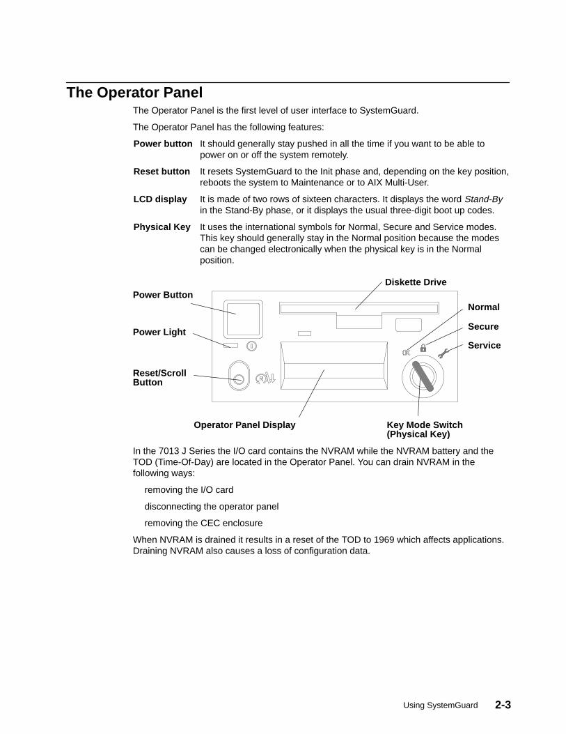
Using SystemGuard 2-3
The Operator PanelThe Operator Panel is the first level of user interface to SystemGuard.
The Operator Panel has the following features:
Power button It should generally stay pushed in all the time if you want to be able topower on or off the system remotely.
Reset button It resets SystemGuard to the Init phase and, depending on the key position,reboots the system to Maintenance or to AIX Multi-User.
LCD display It is made of two rows of sixteen characters. It displays the word Stand-Byin the Stand-By phase, or it displays the usual three-digit boot up codes.
Physical Key It uses the international symbols for Normal, Secure and Service modes.This key should generally stay in the Normal position because the modescan be changed electronically when the physical key is in the Normalposition.
Operator Panel Display
Reset/ScrollButton
Key Mode Switch(Physical Key)
Power Light
Power ButtonDiskette Drive
Normal
Secure
Service
In the 7013 J Series the I/O card contains the NVRAM while the NVRAM battery and theTOD (Time-Of-Day) are located in the Operator Panel. You can drain NVRAM in thefollowing ways:
removing the I/O card
disconnecting the operator panel
removing the CEC enclosure
When NVRAM is drained it results in a reset of the TOD to 1969 which affects applications.Draining NVRAM also causes a loss of configuration data.
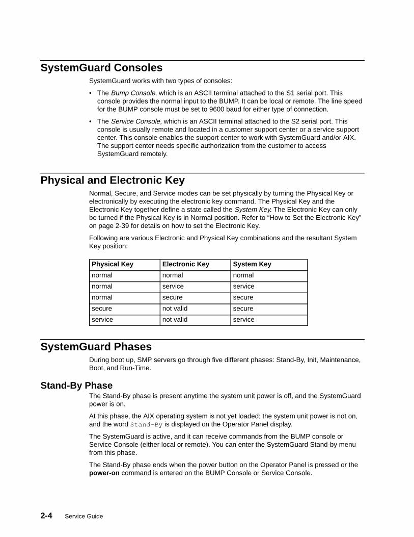
2-4 Service Guide
SystemGuard ConsolesSystemGuard works with two types of consoles:
• The Bump Console, which is an ASCII terminal attached to the S1 serial port. Thisconsole provides the normal input to the BUMP. It can be local or remote. The line speedfor the BUMP console must be set to 9600 baud for either type of connection.
• The Service Console, which is an ASCII terminal attached to the S2 serial port. Thisconsole is usually remote and located in a customer support center or a service supportcenter. This console enables the support center to work with SystemGuard and/or AIX.The support center needs specific authorization from the customer to accessSystemGuard remotely.
Physical and Electronic KeyNormal, Secure, and Service modes can be set physically by turning the Physical Key orelectronically by executing the electronic key command. The Physical Key and theElectronic Key together define a state called the System Key. The Electronic Key can onlybe turned if the Physical Key is in Normal position. Refer to “How to Set the Electronic Key”on page 2-39 for details on how to set the Electronic Key.
Following are various Electronic and Physical Key combinations and the resultant SystemKey position:
Physical Key Electronic Key System Key
normal normal normal
normal service service
normal secure secure
secure not valid secure
service not valid service
SystemGuard PhasesDuring boot up, SMP servers go through five different phases: Stand-By, Init, Maintenance,Boot, and Run-Time.
Stand-By PhaseThe Stand-By phase is present anytime the system unit power is off, and the SystemGuardpower is on.
At this phase, the AIX operating system is not yet loaded; the system unit power is not on,and the word Stand-By is displayed on the Operator Panel display.
The SystemGuard is active, and it can receive commands from the BUMP console orService Console (either local or remote). You can enter the SystemGuard Stand-by menufrom this phase.
The Stand-By phase ends when the power button on the Operator Panel is pressed or thepower-on command is entered on the BUMP Console or Service Console.

Using SystemGuard 2-5
Init PhaseInit phase is entered when the power button on the Operator Panel is pressed on or whenthe power on command is entered on the BUMP Console or Service Console.
If the System Key is in Normal mode, the BUMP runs the built-in or resident power-on(PON)-tests on the CPU module hardware, IPLs on the first available processor, runs thefunctional power on self-tests (POST) on the I/O subsystem to check the system, and finallyloads the AIX operating system.
If the System Key is in Service mode, and if several conditions are met, the system loadsthe SystemGuard MAINTENANCE MENU. These conditions are: the Autoservice IPL flagdisabled, the BUMP console enabled, and a Valid Service Contract.
If the System Key is in Secure mode, the system enters the Stall state, and the LCDdisplays the three-digit code 200. The initialization of the system stops until the Physical Keyis set to Normal or Service. The Stall state is exited, and control of the system is passed toAIX.
Maintenance PhaseThe maintenance phase is entered from the Init phase if the system key is in service mode.
If the BUMP console present flag is set, the MAINTENANCE MENU is displayed on theBUMP console, and the system waits for an operator action. The maintenance menuchoices are described on page 2-21. Various maintenance tasks can be performed from thismenu. When maintenance tasks are complete, the system can be booted, powered down, orreset.
Boot PhaseSystemGuard enters the Boot phase from either the Init phase or the Maintenance phase. Inthis phase the system is initialized and control of the system is passed to the operatingsystem. Control of the two serial ports is switched to the operating system and the Run-Timephase is entered. If a valid boot block is not found and the system key is set to Service,SystemGuard returns to the Maintenance phase.
Run-Time PhaseThis is the phase where the AIX operating system is in control of the system. The Run-Timephase is entered once the AIX operating system is loaded and takes control of the consoles.
When AIX is stopped again, for example due to a shutdown, the system goes back to theStand-By phase.

2-6 Service Guide
Phase Change (Stand-By to Init)The phase change from Stand-By to Init is called Crossing The Power boundary. This isachieved by pushing the power button on the Operator Panel or by typing the keywordpower at the Stand-By prompt (>). Note that if you type power while the power button is notpushed in, nothing happens until you press the power button. In this case, the powercommand has been taken into account by SystemGuard, and you don’t have to reenter it.The power command is the default power on command sequence, which you can changefrom the maintenance menu or AIX service aids.
SystemGuard, checks for a special downloadable diskette (if in Service mode), checks theFlash EEPROM, and then produces an output. The following is an example of what appears:
BUMP FIRMWARE – February 16, 1995 ID 07.01 – POWER_ON in EPROM # FLOPPY NOT READY! DO YOU WANT TO UPDATE FLASH FROM LINE S2[y/n]? n BUMP FIRMWARE – May 19, 1995 ID xx.xx – POWER_ON in FLASH PROM
The message FLOPPY NOT READY! means that there is no specific downloadable diskettein the diskette drive.
Note: This message is only displayed when IPLing in Service mode.
The special diskette could be:
• Code to be downloaded into Flash EEPROM
• Code to change the VPD in the EEPROMs of the SMP system
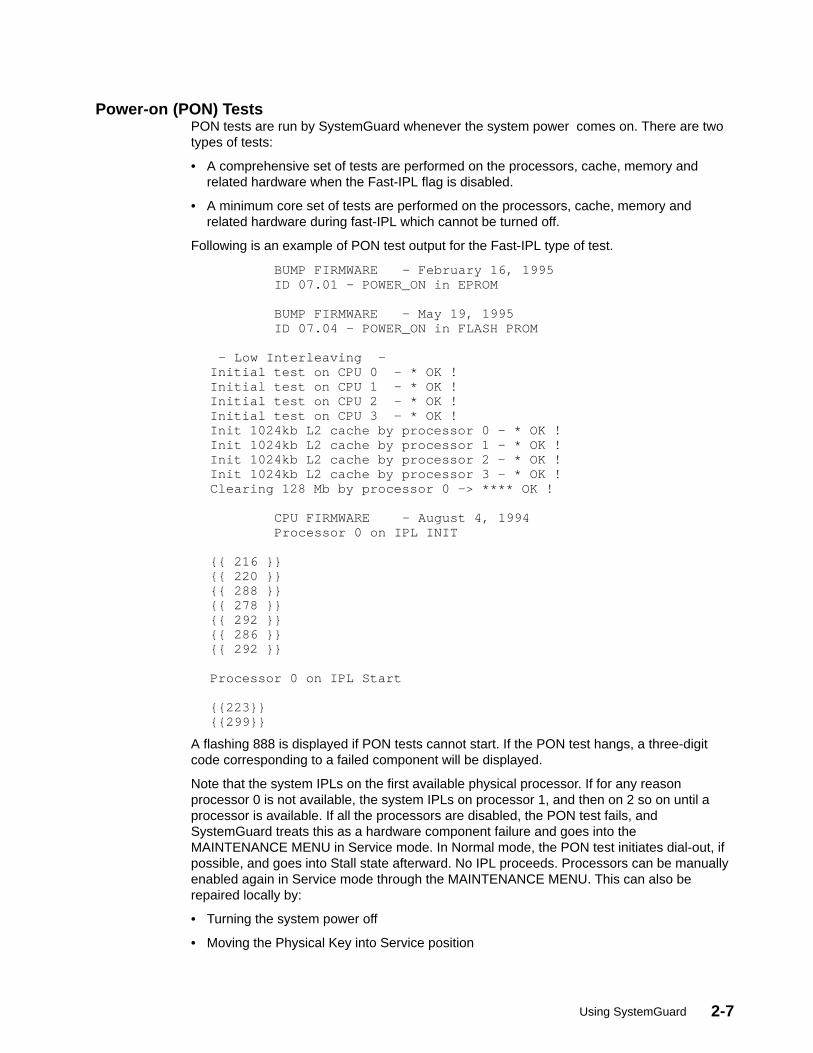
Using SystemGuard 2-7
Power-on (PON) TestsPON tests are run by SystemGuard whenever the system power comes on. There are twotypes of tests:
• A comprehensive set of tests are performed on the processors, cache, memory andrelated hardware when the Fast-IPL flag is disabled.
• A minimum core set of tests are performed on the processors, cache, memory andrelated hardware during fast-IPL which cannot be turned off.
Following is an example of PON test output for the Fast-IPL type of test.
BUMP FIRMWARE – February 16, 1995 ID 07.01 – POWER_ON in EPROM BUMP FIRMWARE – May 19, 1995 ID 07.04 – POWER_ON in FLASH PROM – Low Interleaving –Initial test on CPU 0 – * OK !Initial test on CPU 1 – * OK !Initial test on CPU 2 – * OK !Initial test on CPU 3 – * OK !Init 1024kb L2 cache by processor 0 – * OK !Init 1024kb L2 cache by processor 1 – * OK !Init 1024kb L2 cache by processor 2 – * OK !Init 1024kb L2 cache by processor 3 – * OK !Clearing 128 Mb by processor 0 –> **** OK ! CPU FIRMWARE – August 4, 1994 Processor 0 on IPL INIT {{ 216 }}{{ 220 }}{{ 288 }}{{ 278 }}{{ 292 }}{{ 286 }}{{ 292 }} Processor 0 on IPL Start {{223}}{{299}}
A flashing 888 is displayed if PON tests cannot start. If the PON test hangs, a three-digitcode corresponding to a failed component will be displayed.
Note that the system IPLs on the first available physical processor. If for any reasonprocessor 0 is not available, the system IPLs on processor 1, and then on 2 so on until aprocessor is available. If all the processors are disabled, the PON test fails, andSystemGuard treats this as a hardware component failure and goes into theMAINTENANCE MENU in Service mode. In Normal mode, the PON test initiates dial-out, ifpossible, and goes into Stall state afterward. No IPL proceeds. Processors can be manuallyenabled again in Service mode through the MAINTENANCE MENU. This can also berepaired locally by:
• Turning the system power off
• Moving the Physical Key into Service position
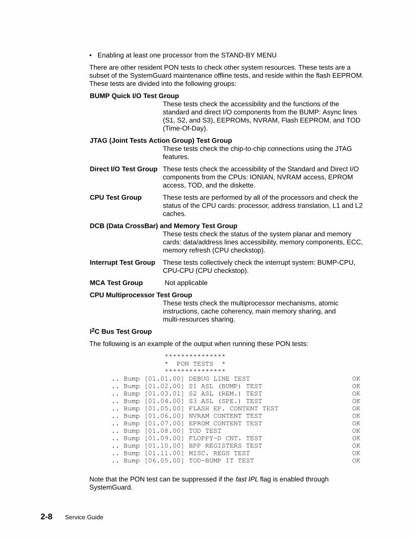
2-8 Service Guide
• Enabling at least one processor from the STAND-BY MENU
There are other resident PON tests to check other system resources. These tests are asubset of the SystemGuard maintenance offline tests, and reside within the flash EEPROM.These tests are divided into the following groups:
BUMP Quick I/O Test GroupThese tests check the accessibility and the functions of thestandard and direct I/O components from the BUMP: Async lines(S1, S2, and S3), EEPROMs, NVRAM, Flash EEPROM, and TOD(Time-Of-Day).
JTAG (Joint Tests Action Group) Test GroupThese tests check the chip-to-chip connections using the JTAGfeatures.
Direct I/O Test Group These tests check the accessibility of the Standard and Direct I/Ocomponents from the CPUs: IONIAN, NVRAM access, EPROMaccess, TOD, and the diskette.
CPU Test Group These tests are performed by all of the processors and check thestatus of the CPU cards: processor, address translation, L1 and L2caches.
DCB (Data CrossBar) and Memory Test GroupThese tests check the status of the system planar and memorycards: data/address lines accessibility, memory components, ECC,memory refresh (CPU checkstop).
Interrupt Test Group These tests collectively check the interrupt system: BUMP-CPU,CPU-CPU (CPU checkstop).
MCA Test Group Not applicable
CPU Multiprocessor Test GroupThese tests check the multiprocessor mechanisms, atomicinstructions, cache coherency, main memory sharing, andmulti-resources sharing.
I2C Bus Test Group
The following is an example of the output when running these PON tests:
*************** * PON TESTS * *************** .. Bump [01.01.00] DEBUG LINE TEST OK .. Bump [01.02.00] S1 ASL (BUMP) TEST OK .. Bump [01.03.01] S2 ASL (REM.) TEST OK .. Bump [01.04.00] S3 ASL (SPE.) TEST OK .. Bump [01.05.00] FLASH EP. CONTENT TEST OK .. Bump [01.06.00] NVRAM CONTENT TEST OK .. Bump [01.07.00] EPROM CONTENT TEST OK .. Bump [01.08.00] TOD TEST OK .. Bump [01.09.00] FLOPPY–D CNT. TEST OK .. Bump [01.10.00] BPP REGISTERS TEST OK .. Bump [01.11.00] MISC. REGS TEST OK .. Bump [06.05.00] TOD–BUMP IT TEST OK
Note that the PON test can be suppressed if the fast IPL flag is enabled throughSystemGuard.
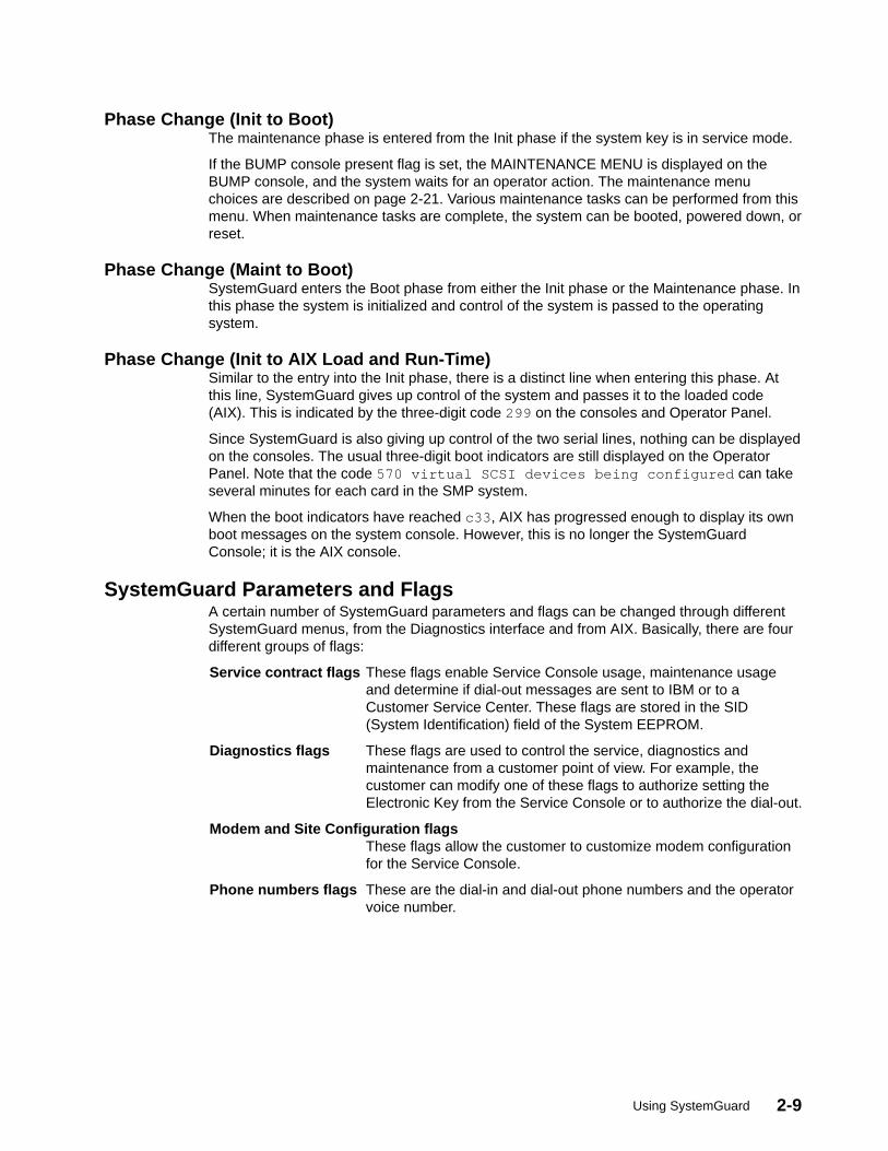
Using SystemGuard 2-9
Phase Change (Init to Boot)The maintenance phase is entered from the Init phase if the system key is in service mode.
If the BUMP console present flag is set, the MAINTENANCE MENU is displayed on theBUMP console, and the system waits for an operator action. The maintenance menuchoices are described on page 2-21. Various maintenance tasks can be performed from thismenu. When maintenance tasks are complete, the system can be booted, powered down, orreset.
Phase Change (Maint to Boot)SystemGuard enters the Boot phase from either the Init phase or the Maintenance phase. Inthis phase the system is initialized and control of the system is passed to the operatingsystem.
Phase Change (Init to AIX Load and Run-Time)Similar to the entry into the Init phase, there is a distinct line when entering this phase. Atthis line, SystemGuard gives up control of the system and passes it to the loaded code(AIX). This is indicated by the three-digit code 299 on the consoles and Operator Panel.
Since SystemGuard is also giving up control of the two serial lines, nothing can be displayedon the consoles. The usual three-digit boot indicators are still displayed on the OperatorPanel. Note that the code 570 virtual SCSI devices being configured can takeseveral minutes for each card in the SMP system.
When the boot indicators have reached c33 , AIX has progressed enough to display its ownboot messages on the system console. However, this is no longer the SystemGuardConsole; it is the AIX console.
SystemGuard Parameters and FlagsA certain number of SystemGuard parameters and flags can be changed through differentSystemGuard menus, from the Diagnostics interface and from AIX. Basically, there are fourdifferent groups of flags:
Service contract flags These flags enable Service Console usage, maintenance usageand determine if dial-out messages are sent to IBM or to aCustomer Service Center. These flags are stored in the SID(System Identification) field of the System EEPROM.
Diagnostics flags These flags are used to control the service, diagnostics andmaintenance from a customer point of view. For example, thecustomer can modify one of these flags to authorize setting theElectronic Key from the Service Console or to authorize the dial-out.
Modem and Site Configuration flagsThese flags allow the customer to customize modem configurationfor the Service Console.
Phone numbers flags These are the dial-in and dial-out phone numbers and the operatorvoice number.
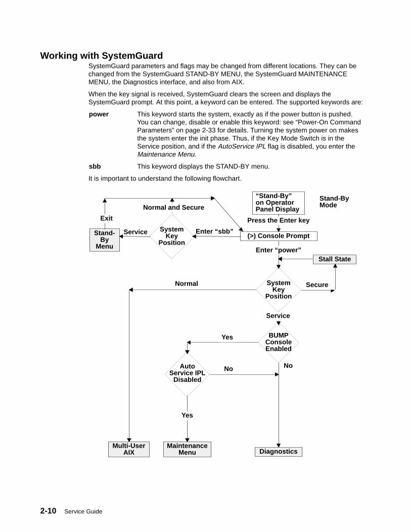
2-10 Service Guide
Working with SystemGuardSystemGuard parameters and flags may be changed from different locations. They can bechanged from the SystemGuard STAND-BY MENU, the SystemGuard MAINTENANCEMENU, the Diagnostics interface, and also from AIX.
When the key signal is received, SystemGuard clears the screen and displays theSystemGuard prompt. At this point, a keyword can be entered. The supported keywords are:
power This keyword starts the system, exactly as if the power button is pushed.You can change, disable or enable this keyword: see “Power-On CommandParameters” on page 2-33 for details. Turning the system power on makesthe system enter the init phase. Thus, if the Key Mode Switch is in theService position, and if the AutoService IPL flag is disabled, you enter theMaintenance Menu.
sbb This keyword displays the STAND-BY menu.
It is important to understand the following flowchart.
“Stand-By”on OperatorPanel Display
Stand-ByMode
Stand-By
Menu
Service SystemKey
Position
Normal and Secure
Exit
Enter “sbb”(>) Console Prompt
Enter “power”
SystemKey
Position
Service
BUMPConsoleEnabled
NoAutoService IPL
Disabled
No
Yes
Secure
Multi-UserAIX
MaintenanceMenu
Stall State
Diagnostics
Normal
Press the Enter key
Yes
Using SystemGuard 2-11
When the system is in Stand-By mode and the System Key (Physical or Electronic Key) is inService mode, the STAND-BY MENU can be accessed and SystemGuard executed.
If you turn the system unit power on from Stand-By mode with the System Key in the Normalposition, the system boots to AIX Multi-User.
If you turn the system unit power on with the System Key in the Service position, you can goto the MAINTENANCE MENU or to Diagnostics, depending on the state of three flags:SystemGuard Console Present, Autoservice IPL, and Service Contract Validity.
If you power on the system with the System Key in Secure, the system stalls.
Here is some information on the meaning of the different flags:
BUMP Console Present flagWhen the BUMP console is enabled, the LED codes and System Guardmessages are displayed on the console during the Init phase. If the BUMPconsole is not enabled, it is like a regular system; no codes and nomessages are displayed on the console during the Init phase. Only AIXmessages appear when the system starts loading AIX.
Note that if you are running the level 5 of the SystemGuard firmware, theBUMP Console is disabled by default, and if you enable it, it is disabled afterevery shutdown. If your system is in Service mode, you might go toDiagnostics instead of Maintenance due the SystemGuard Console beingdisabled by default.
If you are running level 7 or higher of the SystemGuard firmware, the BUMPConsole is enabled by default and stays enabled after a shutdown.
Autoservice IPL flagIf enabled, this flag means that you want to go to Diagnostics when bootingwith the System Key in Service mode.
Service Contract flagThis flag is preset at the factory and is not variable. The Service Contract isalways valid. This flag allows the service center to access the system anddo some maintenance. The Service Contract is set by default to anunlimited number of days (exactly 32767 days).
SystemGuard MenusSystemGuard menus are low-level menus; they make extensive use of abbreviations oracronyms. Refer to the glossary on page X-1 for a full list of these acronyms andabbreviations.
SystemGuard is menu-driven, and menu choices are usually numbered. Letters aresometimes used and can be entered in either lowercase or uppercase (SystemGuard iscase insensitive). The letter x is often used to exit the current menu and return to theprevious menu (or leave SystemGuard, if given from the main menu). Commands are onlytreated after you press the Enter key. Until you press the Enter key, you can use theBackspace key to edit a command. If you enter a command that does not match theavailable options, a beep signals that an invalid selection has been made.
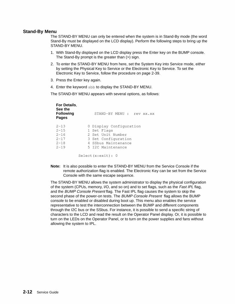
2-12 Service Guide
Stand-By MenuThe STAND-BY MENU can only be entered when the system is in Stand-By mode (the wordStand-By must be displayed on the LCD display). Perform the following steps to bring up theSTAND-BY MENU.
1. With Stand-By displayed on the LCD display press the Enter key on the BUMP console.The Stand-By prompt is the greater than (>) sign.
2. To enter the STAND-BY MENU from here, set the System Key into Service mode, eitherby setting the Physical Key to Service or the Electronic Key to Service. To set theElectronic Key to Service, follow the procedure on page 2-39.
3. Press the Enter key again.
4. Enter the keyword sbb to display the STAND-BY MENU.
The STAND-BY MENU appears with several options, as follows:
For Details ,See the Following STAND–BY MENU : rev xx.xxPages 2-13 0 Display Configuration2-15 1 Set Flags2-16 2 Set Unit Number2-17 3 Set Configuration2-18 4 SSbus Maintenance2-19 5 I2C Maintenance Select(x:exit): 0
Note: It is also possible to enter the STAND-BY MENU from the Service Console if theremote authorization flag is enabled. The Electronic Key can be set from the ServiceConsole with the same escape sequence.
The STAND-BY MENU allows the system administrator to display the physical configurationof the system (CPUs, memory, I/O, and so on) and to set flags, such as the Fast IPL flag,and the BUMP Console Present flag. The Fast IPL flag causes the system to skip thesecond phase of the power-on tests. The BUMP Console Present flag allows the BUMPconsole to be enabled or disabled during boot up. This menu also enables the servicerepresentative to test the interconnection between the BUMP and different componentsthrough the I2C bus or the SSbus. For instance, it is possible to send a specific string ofcharacters to the LCD and read the result on the Operator Panel display. Or, it is possible toturn on the LEDs on the Operator Panel, or to turn on the power supplies and fans withoutallowing the system to IPL.
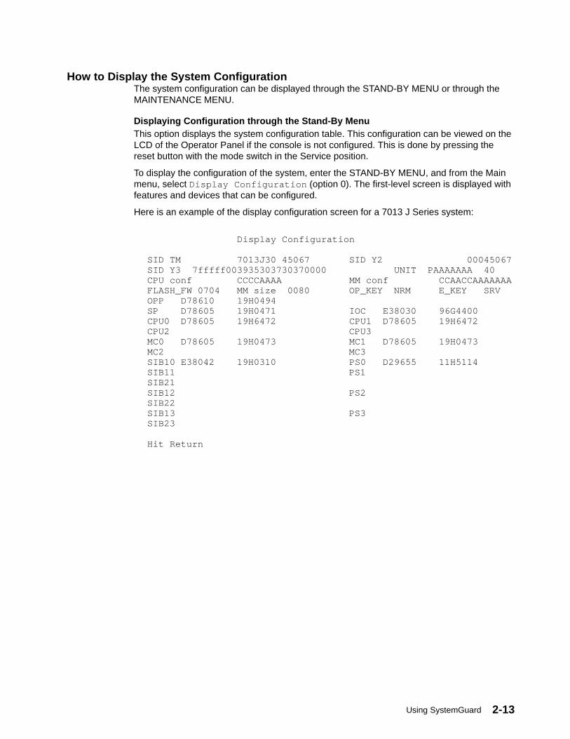
Using SystemGuard 2-13
How to Display the System ConfigurationThe system configuration can be displayed through the STAND-BY MENU or through theMAINTENANCE MENU.
Displaying Configuration through the Stand-By MenuThis option displays the system configuration table. This configuration can be viewed on theLCD of the Operator Panel if the console is not configured. This is done by pressing thereset button with the mode switch in the Service position.
To display the configuration of the system, enter the STAND-BY MENU, and from the Mainmenu, select Display Configuration (option 0). The first-level screen is displayed withfeatures and devices that can be configured.
Here is an example of the display configuration screen for a 7013 J Series system:
Display Configuration SID TM 7013J30 45067 SID Y2 00045067SID Y3 7fffff003935303730370000 UNIT PAAAAAAA 40CPU conf CCCCAAAA MM conf CCAACCAAAAAAAFLASH_FW 0704 MM size 0080 OP_KEY NRM E_KEY SRVOPP D78610 19H0494SP D78605 19H0471 IOC E38030 96G4400CPU0 D78605 19H6472 CPU1 D78605 19H6472CPU2 CPU3MC0 D78605 19H0473 MC1 D78605 19H0473MC2 MC3SIB10 E38042 19H0310 PS0 D29655 11H5114SIB11 PS1SIB21SIB12 PS2SIB22SIB13 PS3SIB23 Hit Return

2-14 Service Guide
Display Configuration
SIB14 PS04 SIB24SIB15 PS05SIB25SIB16 PS06SIB26 fc8e000000000000SIB17 PS07SIB27MP D78605 19H0464 MPe D78605 MCA 01 C fc8e000000000000 MCAe 01 C e1ff000000000000MCA 02 C f48e000000000000 MCAe 02 C 708f000000000000MCA 03 C fc8e000000000000 MCAe 03 C ec8f000000000000MCA 04 C ffde000000000000 MCAe 04 C fc8e000000000000MCA 05 C 14e0000000000000 MCAe 05 C f0ef000000000000MCA 06 C fc8e000000000000 MCAe 06 C 7f8f000000000000MCA 07 C fc8e000000000000 MCAe 07 C fc8e000000000000MCA 08 A fc8e000000000000 MCAe 08 C fc8e000000000000 Hit Return
The meanings of the configuration display fields are as follows:
• SID Y2: This is the system identification information. It is automatically updated when theback plane is changed.
• SID TM: This indicates the type of the model.
• SID Y3: This parameter gives the maintenance contract information in order to enableservice facilities.
• FLASH_FW: This is the Flash EEPROM firmware release number. The correspondingsecond column gives the memory size expressed in KB.
• CPU Conf: This gives the status information of the CPU module (present, absent,deconfigured, or temporarily deconfigured).
• MM Conf: This is the status information for the memory DIMM.
• UNIT ssssssss: This gives the unit status information. The corresponding second columndisplays the number of RDS devices present in each unit. Each unit is denoted by twohexadecimal digits (the first stands for RDS1 and the second for RDS2).
• SIBx EC: This indicates the system interface board (SIB) status information and the vitalproduct data (VPD) identifier.
• PSx EC: The power supply status and the corresponding VPD identifier information isprovided.
• SP EC+s: This parameter gives the status information and the VPD identifier of thesystem planar. The technical status information is also included.
• IOC EC+s: This parameter gives the status information and the VPD identifier of the I/Ocard (IOC).
• OP EC+s: This field gives the operator panel (OP) VPD values and the correspondingstatus information.
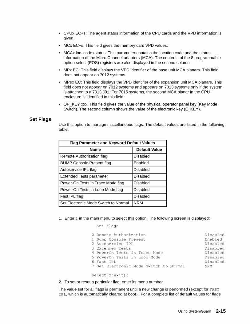
Using SystemGuard 2-15
• CPUx EC+s: The agent status information of the CPU cards and the VPD information isgiven.
• MCx EC+s: This field gives the memory card VPD values.
• MCAx loc. code+status: This parameter contains the location code and the statusinformation of the Micro Channel adapters (MCA). The contents of the 8 programmableoption select (POS) registers are also displayed in the second column.
• MPx EC: This field displays the VPD identifier of the base unit MCA planars. This fielddoes not appear on 7012 systems.
• MPex EC: This field displays the VPD identifier of the expansion unit MCA planars. Thisfield does not appear on 7012 systems and appears on 7013 systems only if the systemis attached to a 7013 J01. For 7015 systems, the second MCA planar in the CPUenclosure is identified in this field.
• OP_KEY xxx: This field gives the value of the physical operator panel key (Key ModeSwitch). The second column shows the value of the electronic key (E_KEY).
Set FlagsUse this option to manage miscellaneous flags. The default values are listed in the followingtable:
Flag Parameter and Keyword Default Values
Name Default Value
Remote Authorization flag Disabled
BUMP Console Present flag Enabled
Autoservice IPL flag Disabled
Extended Tests parameter Disabled
Power-On Tests in Trace Mode flag Disabled
Power-On Tests in Loop Mode flag Disabled
Fast IPL flag Disabled
Set Electronic Mode Switch to Normal NRM
1. Enter 1 in the main menu to select this option. The following screen is displayed:
Set Flags
0 Remote Authorization Disabled 1 Bump Console Present Enabled 2 Autoservice IPL Disabled 3 Extended Tests Disabled 4 PowerOn Tests in Trace Mode Disabled 5 PowerOn Tests in Loop Mode Disabled 6 Fast IPL Disabled 7 Set Electronic Mode Switch to Normal NRM
select(x:exit):
2. To set or reset a particular flag, enter its menu number.
The value set for all flags is permanent until a new change is performed (except for FASTIPL , which is automatically cleared at boot) . For a complete list of default values for flags

2-16 Service Guide
and parameters (set during manufacturing), see the table in “Default Parameter Values” onpage B–1 of the service guide for your system. The following flags can be managed:
• Remote Authorization: Only the local operator can enable this flag to enable remotemaintenance to be performed. Both the local and remote operators can disable it.
• BUMP Console Present: If enabled, SystemGuard displays the MAINTENANCE MENUon the BUMP console (line S1). If disabled, the MAINTENANCE MENU is not availableon the BUMP console.
• Autoservice IPL: When enabled, this flag enables an automatic IPL even if the Key ModeSwitch is in the Service position, thus avoiding the display of the MAINTENANCE MENU.
• Extended Tests: This parameter determines under what conditions extended power onself-tests are run at IPL time, after the regular power on self-tests (POSTs). If theparameter is enabled, the extended tests are run. If the parameter is disabled, theextended tests are not run.
• Power-On Tests in Trace Mode: When enabled, supports the running of POST tests intrace mode, which gives extra information about how tests are conducted. A dedicated ttyline is required, this is to be used only when directed by service support personnel.
• Power-On Tests in Loop Mode: When enabled, SystemGuard loops on the POST testsand does not IPL.
• Fast IPL: When enabled, the long POST tests are not run, shortening the INIT phase.This feature lets you start the machine quickly, when the test performance is notnecessary. This flag is not permanent. It only remains set until the next IPL, at which pointit is automatically cleared.
• Set Electronic Mode Switch to Normal: This command sets the Electronic Mode Switch tothe Normal position. Keep in mind that the Electronic Mode Switch is only taken intoaccount if the Key Mode Switch is in the Normal position. The Electronic Mode Switch isalso set to Normal each time the Key Mode Switch is moved.
Set Unit NumberUse this option to assign logical numbers to units that you add to your system.
Whenever a new unit is added, this command must be run to update the unit configurationtable.
Simply enter 2 in the main STAND-BY MENU to select this option. The process of assigninga unit number is automatic: there is no need to pick a number.
An RS-485 bus interconnects all system and expansion units, each being addressed using alogical number of 0 or 1. The base unit, where the SystemGuard and the operator panel arepresent is the master of the RS-485 bus, and is always given logical number 0. The firstexpansion unit is assigned the logical number 1.
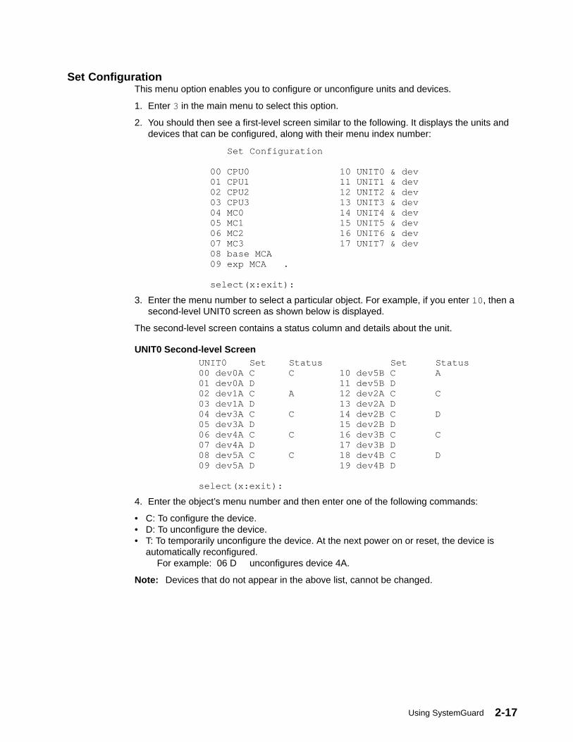
Using SystemGuard 2-17
Set ConfigurationThis menu option enables you to configure or unconfigure units and devices.
1. Enter 3 in the main menu to select this option.
2. You should then see a first-level screen similar to the following. It displays the units anddevices that can be configured, along with their menu index number:
Set Configuration
00 CPU0 10 UNIT0 & dev 01 CPU1 11 UNIT1 & dev 02 CPU2 12 UNIT2 & dev 03 CPU3 13 UNIT3 & dev 04 MC0 14 UNIT4 & dev 05 MC1 15 UNIT5 & dev 06 MC2 16 UNIT6 & dev 07 MC3 17 UNIT7 & dev 08 base MCA 09 exp MCA .
select(x:exit):
3. Enter the menu number to select a particular object. For example, if you enter 10 , then asecond-level UNIT0 screen as shown below is displayed.
The second-level screen contains a status column and details about the unit.
UNIT0 Second-level Screen UNIT0 Set Status Set Status
00 dev0A C C 10 dev5B C A 01 dev0A D 11 dev5B D 02 dev1A C A 12 dev2A C C 03 dev1A D 13 dev2A D 04 dev3A C C 14 dev2B C D 05 dev3A D 15 dev2B D 06 dev4A C C 16 dev3B C C 07 dev4A D 17 dev3B D 08 dev5A C C 18 dev4B C D 09 dev5A D 19 dev4B D
select(x:exit):
4. Enter the object’s menu number and then enter one of the following commands:
• C: To configure the device.• D: To unconfigure the device.• T: To temporarily unconfigure the device. At the next power on or reset, the device is
automatically reconfigured.For example: 06 D unconfigures device 4A.
Note: Devices that do not appear in the above list, cannot be changed.
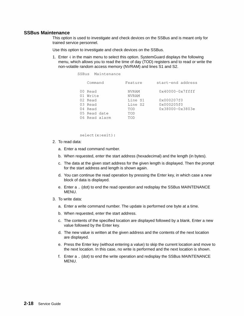
2-18 Service Guide
SSBus MaintenanceThis option is used to investigate and check devices on the SSBus and is meant only fortrained service personnel.
Use this option to investigate and check devices on the SSBus.
1. Enter 4 in the main menu to select this option. SystemGuard displays the followingmenu, which allows you to read the time of day (TOD) registers and to read or write thenon-volatile random access memory (NVRAM) and lines S1 and S2.
SSBus Maintenance
Command Feature start–end address
00 Read NVRAM 0x40000–0x7ffff 01 Write NVRAM 02 Read Line S1 0x000207f0 03 Read Line S2 0x000205f0 04 Read TOD 0x38000–0x3803e 05 Read date TOD 06 Read alarm TOD
select(x:exit):
2. To read data:
a. Enter a read command number.
b. When requested, enter the start address (hexadecimal) and the length (in bytes).
c. The data at the given start address for the given length is displayed. Then the promptfor the start address and length is shown again.
d. You can continue the read operation by pressing the Enter key, in which case a newblock of data is displayed.
e. Enter a . (dot) to end the read operation and redisplay the SSBus MAINTENANCEMENU.
3. To write data:
a. Enter a write command number. The update is performed one byte at a time.
b. When requested, enter the start address.
c. The contents of the specified location are displayed followed by a blank. Enter a newvalue followed by the Enter key.
d. The new value is written at the given address and the contents of the next locationare displayed.
e. Press the Enter key (without entering a value) to skip the current location and move tothe next location. In this case, no write is performed and the next location is shown.
f. Enter a . (dot) to end the write operation and redisplay the SSBus MAINTENANCEMENU.
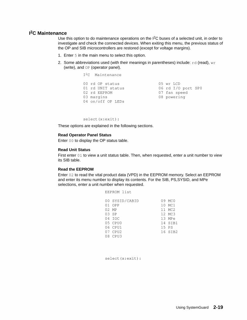
Using SystemGuard 2-19
I2C MaintenanceUse this option to do maintenance operations on the I2C buses of a selected unit, in order toinvestigate and check the connected devices. When exiting this menu, the previous status ofthe OP and SIB microcontrollers are restored (except for voltage margins).
1. Enter 5 in the main menu to select this option.
2. Some abbreviations used (with their meanings in parentheses) include: rd (read), wr(write), and OP (operator panel).
I 2C Maintenance
00 rd OP status 05 wr LCD01 rd UNIT status 06 rd I/O port SP002 rd EEPROM 07 fan speed03 margins 08 powering04 on/off OP LEDs
select(x:exit):
These options are explained in the following sections.
Read Operator Panel StatusEnter 00 to display the OP status table.
Read Unit StatusFirst enter 01 to view a unit status table. Then, when requested, enter a unit number to viewits SIB table.
Read the EEPROMEnter 02 to read the vital product data (VPD) in the EEPROM memory. Select an EEPROMand enter its menu number to display its contents. For the SIB, PS,SYSID, and MPeselections, enter a unit number when requested.
EEPROM list
00 SYSID/CABID 09 MC0 01 OPP 10 MC1 02 MP 11 MC2 03 SP 12 MC3 04 IOC 13 MPe 05 CPU0 14 SIB1 06 CPU1 15 PS 07 CPU2 16 SIB2 08 CPU3
select(x:exit):
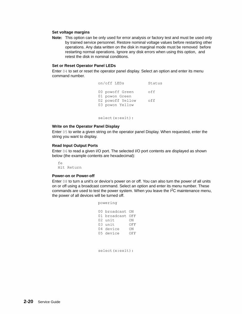
2-20 Service Guide
Set voltage marginsNote: This option can be only used for error analysis or factory test and must be used only
by trained service personnel. Restore nominal voltage values before restarting otheroperations. Any data written on the disk in marginal mode must be removed beforerestarting normal operations. Ignore any disk errors when using this option, andretest the disk in nominal conditions.
Set or Reset Operator Panel LEDsEnter 04 to set or reset the operator panel display. Select an option and enter its menucommand number.
on/off LEDs Status
00 powoff Green off 01 powon Green 02 powoff Yellow off 03 powon Yellow
select(x:exit):
Write on the Operator Panel DisplayEnter 05 to write a given string on the operator panel Display. When requested, enter thestring you want to display.
Read Input Output PortsEnter 06 to read a given I/O port. The selected I/O port contents are displayed as shownbelow (the example contents are hexadecimal):
feHit Return
Power-on or Power-offEnter 08 to turn a unit’s or device’s power on or off. You can also turn the power of all unitson or off using a broadcast command. Select an option and enter its menu number. Thesecommands are used to test the power system. When you leave the I2C maintenance menu,the power of all devices will be turned off.
powering
00 broadcast ON 01 broadcast OFF 02 unit ON 03 unit OFF 04 device ON 05 device OFF
select(x:exit):
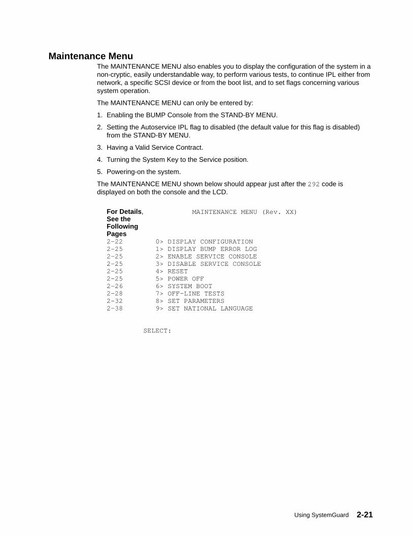
Using SystemGuard 2-21
Maintenance MenuThe MAINTENANCE MENU also enables you to display the configuration of the system in anon-cryptic, easily understandable way, to perform various tests, to continue IPL either fromnetwork, a specific SCSI device or from the boot list, and to set flags concerning varioussystem operation.
The MAINTENANCE MENU can only be entered by:
1. Enabling the BUMP Console from the STAND-BY MENU.
2. Setting the Autoservice IPL flag to disabled (the default value for this flag is disabled)from the STAND-BY MENU.
3. Having a Valid Service Contract.
4. Turning the System Key to the Service position.
5. Powering-on the system.
The MAINTENANCE MENU shown below should appear just after the 292 code isdisplayed on both the console and the LCD.
For Details , MAINTENANCE MENU (Rev. XX)See the FollowingPages2-22 0> DISPLAY CONFIGURATION2-25 1> DISPLAY BUMP ERROR LOG2-25 2> ENABLE SERVICE CONSOLE2-25 3> DISABLE SERVICE CONSOLE2-25 4> RESET2-25 5> POWER OFF2-26 6> SYSTEM BOOT2-28 7> OFF–LINE TESTS2-32 8> SET PARAMETERS2-38 9> SET NATIONAL LANGUAGE SELECT:
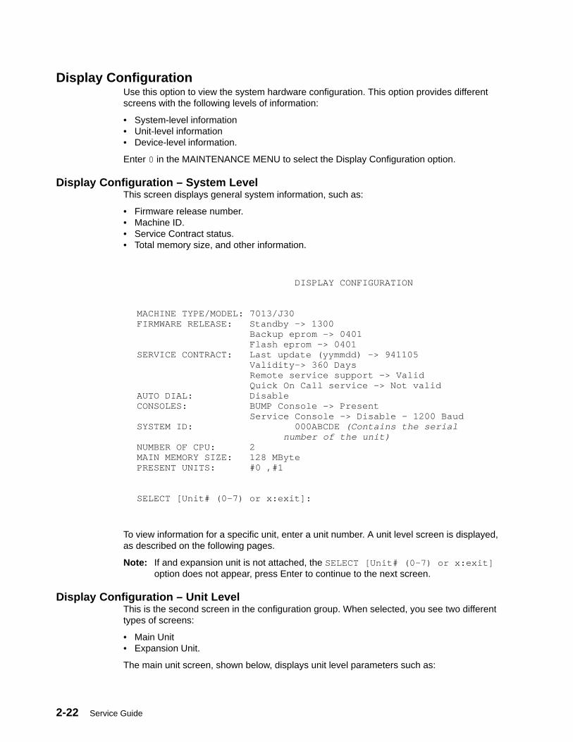
2-22 Service Guide
Display ConfigurationUse this option to view the system hardware configuration. This option provides differentscreens with the following levels of information:
• System-level information• Unit-level information• Device-level information.
Enter 0 in the MAINTENANCE MENU to select the Display Configuration option.
Display Configuration – System LevelThis screen displays general system information, such as:
• Firmware release number.• Machine ID.• Service Contract status.• Total memory size, and other information.
DISPLAY CONFIGURATION
MACHINE TYPE/MODEL: 7013/J30FIRMWARE RELEASE: Standby –> 1300 Backup eprom –> 0401 Flash eprom –> 0401SERVICE CONTRACT: Last update (yymmdd) –> 941105 Validity–> 360 Days Remote service support –> Valid Quick On Call service –> Not validAUTO DIAL: DisableCONSOLES: BUMP Console –> Present Service Console –> Disable – 1200 BaudSYSTEM ID: 000ABCDE (Contains the serial number of the unit)NUMBER OF CPU: 2MAIN MEMORY SIZE: 128 MBytePRESENT UNITS: #0 ,#1
SELECT [Unit# (0–7) or x:exit]:
To view information for a specific unit, enter a unit number. A unit level screen is displayed,as described on the following pages.
Note: If and expansion unit is not attached, the SELECT [Unit# (0–7) or x:exit]option does not appear, press Enter to continue to the next screen.
Display Configuration – Unit LevelThis is the second screen in the configuration group. When selected, you see two differenttypes of screens:
• Main Unit• Expansion Unit.
The main unit screen, shown below, displays unit level parameters such as:
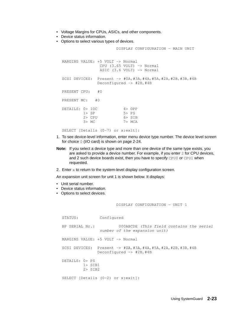
Using SystemGuard 2-23
• Voltage Margins for CPUs, ASICs, and other components.• Device status information.• Options to select various types of devices.
DISPLAY CONFIGURATION – MAIN UNIT
MARGINS VALUE: +5 VOLT –> Normal CPU (3.65 VOLT) –> Normal ASIC (3.6 VOLT) –> Normal
SCSI DEVICES: Present –> #0A,#3A,#4A,#5A,#2A,#2B,#3B,#4B Deconfigured –> #2B,#4B
PRESENT CPU: #0
PRESENT MC: #0
DETAILS: 0> IOC 4> OPP 1> SP 5> PS 2> CPU 6> SIB 3> MC 7> MCA
SELECT [Details (0–7) or x:exit]:
1. To see device-level information, enter menu device type number. The device level screenfor choice 0 (I/O card) is shown on page 2-24.
Note: If you select a device type and more than one device of the same type exists, youare asked to provide a device number. For example, if you enter 2 for CPU devices,and 2 such device boards exist, then you have to specify CPU0 or CPU1 whenrequested.
2. Enter x to return to the system-level display configuration screen.
An expansion unit screen for unit 1 is shown below. It displays:
• Unit serial number.• Device status information.• Options to select devices.
DISPLAY CONFIGURATION – UNIT 1
STATUS: Configured
BP SERIAL Nr.: 000ABCDE (This field contains the serial number of the expansion unit)
MARGINS VALUE: +5 VOLT –> Normal
SCSI DEVICES: Present –> #0A,#3A,#4A,#5A,#2A,#2B,#3B,#4B Deconfigured –> #2B,#4B
DETAILS: 0> PS 1> SIB1 2> SIB2
SELECT [Details (0–2) or x:exit]:

2-24 Service Guide
1. To see device-level information, enter the corresponding command number for thedevice. The device-level screen is displayed.
2. Enter x to return to the system-level configuration display screen.
Display Configuration – Device LevelThis screen is shown when you select one of the devices of your choice from either the MainUnit or Unit 1 screen. This option enables viewing of individual device information as shownin the following representative screen:
• Results of diagnostic tests, such as built-in or power on self-tests (PON or POST).
• Device specific vital product data (VPD) information such as:
– Engineering change level.– Device field-replaceable unit (FRU) number.– Name of the manufacturer.– Processor component definition (related to the position of the ASICs).– Unit part number.
Note: The VPD information (restricted access) is stored in the embedded EEPROM and onboard permanent memories.
DISPLAY CONFIGURATION – MAIN UNIT (IOC)BIST/POST: 0x0000
IOC VPD:*EC 002 D6*FN IOC*MN IBM97N*PC 0001020500020004000101000001*PN ABCDEFGH (Will contain the part number, depending on the system)*RL 76971323–03276971316–031 *RM 176971331–03176706743–00104010406*SN A0P0203400000000*Y0 00 00ABCDE7013/J30 (CONTAINS THE SERIAL NUMBER OF THE SYSTEM UNIT
PRESS RETURN TO EXIT:
Enter the Enter key to exit and return to the previous screen.

Using SystemGuard 2-25
Display BUMP Error LogUse this option to view the BUMP firmware error log.
1. Enter 1 in the MAINTENANCE MENU to select this option. The contents of the loggingbuffer are displayed as shown in the following screen:
DISPLAY BUMP ERROR LOG
EVENT # 1:
401401000000000000000000000000000000000000000000000000000000000000000000000000000000000000000000000000000000000000000000000000000000000000000000000000000000000000000000000000000000000000000000000000000000000000000000000000000000000000000000000000000000000000000000000000000000000000000000000000000000000000000000000000000000000000000000000000000000000000000000000000000000000000000000000000
SELECT [+:forward event or x:exit]:
2. Use the + and – keys to scroll events on the screen forward and backward, respectively.
3. Press x to exit and return to the main menu.
Enable Service ConsoleUse this command to enable remote service support on the S2 line by setting the RemoteAuthorization flag. Only the local operator can perform this command.
When this flag is enabled, remote service support is possible and all characters sent on lineS1 or line S2 are also sent on the other line.
• Enter 2 in the MAINTENANCE MENU to enable the Remote Authorization flag.
Disable Service ConsoleUse this command to prevent remote service support by disabling the Remote Authorizationflag. This can be performed as a security measure, for example.
• Enter 3 in the MAINTENANCE MENU to disable the Remote Authorization flag.
ResetThis command simulates the reset action. You can use this command instead of pressingthe Reset button on the operator panel (OP).
1. Enter 4 in the MAINTENANCE MENU.
2. Confirm your action, when requested. The system is restarted from scratch, meaning thata new initial program load (IPL) is run.
Power-OffThis command forces an immediate system power off. It is run only after the operatorconfirms the action.
1. Enter 5 in the MAINTENANCE MENU.
2. Confirm your action when requested. The system powers off immediately.
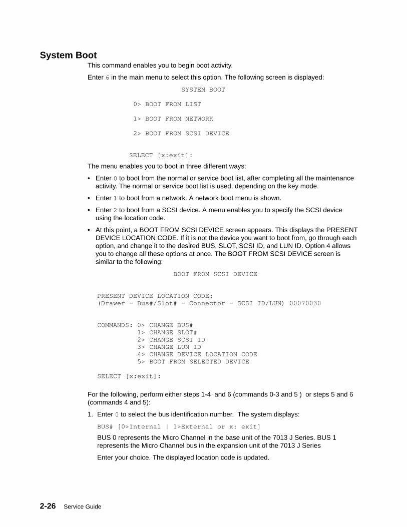
2-26 Service Guide
System BootThis command enables you to begin boot activity.
Enter 6 in the main menu to select this option. The following screen is displayed:
SYSTEM BOOT
0> BOOT FROM LIST
1> BOOT FROM NETWORK
2> BOOT FROM SCSI DEVICE
SELECT [x:exit]:
The menu enables you to boot in three different ways:
• Enter 0 to boot from the normal or service boot list, after completing all the maintenanceactivity. The normal or service boot list is used, depending on the key mode.
• Enter 1 to boot from a network. A network boot menu is shown.
• Enter 2 to boot from a SCSI device. A menu enables you to specify the SCSI deviceusing the location code.
• At this point, a BOOT FROM SCSI DEVICE screen appears. This displays the PRESENTDEVICE LOCATION CODE. If it is not the device you want to boot from, go through eachoption, and change it to the desired BUS, SLOT, SCSI ID, and LUN ID. Option 4 allowsyou to change all these options at once. The BOOT FROM SCSI DEVICE screen issimilar to the following:
BOOT FROM SCSI DEVICE
PRESENT DEVICE LOCATION CODE:(Drawer – Bus#/Slot# – Connector – SCSI ID/LUN) 00070030
COMMANDS: 0> CHANGE BUS# 1> CHANGE SLOT# 2> CHANGE SCSI ID 3> CHANGE LUN ID 4> CHANGE DEVICE LOCATION CODE 5> BOOT FROM SELECTED DEVICE
SELECT [x:exit]:
For the following, perform either steps 1-4 and 6 (commands 0-3 and 5 ) or steps 5 and 6(commands 4 and 5):
1. Enter 0 to select the bus identification number. The system displays:
BUS# [0>Internal | 1>External or x: exit]
BUS 0 represents the Micro Channel in the base unit of the 7013 J Series. BUS 1represents the Micro Channel bus in the expansion unit of the 7013 J Series
Enter your choice. The displayed location code is updated.
Using SystemGuard 2-27
2. Enter 1 to select the slot number. The system displays:
SLOT# [1–7 (Internal Bus) | 1–8 (External Bus) or x: exit]
Enter your choice. The displayed location code is updated.
Note: Bus choice is not available on 7012 systems.
3. Enter 2 to select the SCSI identification number. The system displays:
SCSI ID [0–F or x: exit]
Enter your choice. The displayed location code is updated.
4. Enter 3 to select the logical unit identification number (LUN ID). The system displays:
LUN ID [0–F (8 bit bus) | 00–1F (16 bit bus) or x: exit]
Enter your choice. The displayed location code is updated.
Another method of changing the SCSI Boot Device location code is to select 4 from theBOOT FROM SCSI DEVICE menu. This method allows you to change the SLOT #, SCSIID, and the LUN ID simultaneously. When you make this selection, the system displays:
ENTER LOCATION CODE(Drawer – Bus#/Slot# – Connector – SCSI ID/LUN):
Enter the new location code in the form AA–BB–CC–DD, where AA is the drawernumber, BB is the bus and slot number, CC is the connector, and DD is the SCSIidentifier and logical unit identifier.
Enter 5 to begin the boot. The system leaves the maintenance environment and boots fromthe specified SCSI device.

2-28 Service Guide
Off-Line TestsAttention: These menus are only to be used when directed by service support personnel.Some of the tests described require test equipment or resources not available on yoursystem.
This option under the MAINTENANCE MENU enables you to run the off-line tests in acontrolled and interactive mode.
• Enter 7 in the MAINTENANCE MENU to select the Off Line Tests option. The followingmenu is displayed.
OFF-LINE TESTS MenuThe OFF-LINE TESTS main menu, that follows, uses an empty option list by default.
OFF–LINE TESTSOPTION LIST: PROCESSOR LIST: Test parameter value
COMMANDS: A> VERBOSE B> VERBOSE++ C> HALT ON ERROR D> LOOP E> SCOPE F> PROCESSOR
0> BUILD TEST LIST 1> MODIFY/DISPLAY TEST LIST 2> DELETE TEST LIST 3> EXECUTE TEST LIST 4> ERROR REPORT INSPECTION
SELECT [x:exit]:
You can modify the option list field by entering the command corresponding to a particularoption. If you want to deselect a particular option (if you want to cancel the option afterselecting it) press the same command once again. In other words, the options are toggledby the corresponding commands. The available commands are explained as follows:
A Sets the verbose option, which displays test execution messages. Withoutthis option, only test titles and results are displayed.
B Sets the extra verbose option, which displays the verbose messages, plusdetailed test execution messages. If this option is selected, the verboseoption is redundant and is ignored.
C Sets the halt on error option, which forces test execution to stop when thefirst error is found. In this case, the error message and status are displayed.
D Sets the loop option, which continuously runs selected tests in a loop whiledisplaying the test identifier and loop step counter. To stop the tests, pressthe Break key (Ctrl-x).
E Sets the scope option, which continuously runs the first test (in the list ofselected tests) in a loop, without displaying messages. To stop the tests,press the Break key.
F Select the processor to run the tests.
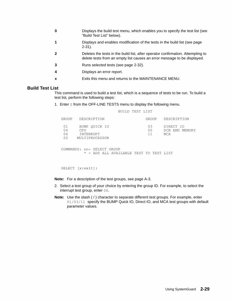
Using SystemGuard 2-29
0 Displays the build test menu, which enables you to specify the test list (see“Build Test List” below).
1 Displays and enables modification of the tests in the build list (see page2-31).
2 Deletes the tests in the build list, after operator confirmation. Attempting todelete tests from an empty list causes an error message to be displayed.
3 Runs selected tests (see page 2-32).
4 Displays an error report.
x Exits this menu and returns to the MAINTENANCE MENU.
Build Test ListThis command is used to build a test list, which is a sequence of tests to be run. To build atest list, perform the following steps:
1. Enter 0 from the OFF-LINE TESTS menu to display the following menu.
BUILD TEST LIST
GROUP DESCRIPTION GROUP DESCRIPTION
01 BUMP QUICK IO 03 DIRECT IO 04 CPU 05 DCB AND MEMORY 06 INTERRUPT 11 MCA 20 MULTIPROCESSOR
COMMANDS: nn> SELECT GROUP * > ADD ALL AVAILABLE TEST TO TEST LIST
SELECT [x:exit]:
Note: For a description of the test groups, see page A-3.
2. Select a test group of your choice by entering the group ID. For example, to select theinterrupt test group, enter 06 .
Note: Use the slash ( / ) character to separate different test groups. For example, enter01/03/11 specify the BUMP Quick IO, Direct IO, and MCA test groups with defaultparameter values.
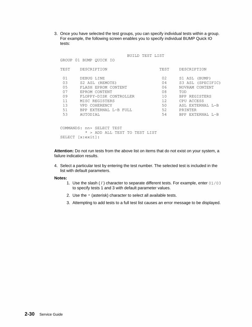
2-30 Service Guide
3. Once you have selected the test groups, you can specify individual tests within a group.For example, the following screen enables you to specify individual BUMP Quick IOtests:
BUILD TEST LISTGROUP 01 BUMP QUICK IO
TEST DESCRIPTION TEST DESCRIPTION
01 DEBUG LINE 02 S1 ASL (BUMP) 03 S2 ASL (REMOTE) 04 S3 ASL (SPECIFIC) 05 FLASH EPROM CONTENT 06 NOVRAM CONTENT 07 EPROM CONTENT 08 TOD 09 FLOPPY-DISK CONTROLLER 10 BPP REGISTERS 11 MISC REGISTERS 12 CPU ACCESS 13 VPD COHERENCY 50 ASL EXTERNAL L-B 51 BPP EXTERNAL L-B FULL 52 PRINTER 53 AUTODIAL 54 BPP EXTERNAL L-B
COMMANDS: nn> SELECT TEST * > ADD ALL TEST TO TEST LIST SELECT [x:exit]:
Attention: Do not run tests from the above list on items that do not exist on your system, afailure indication results.
4. Select a particular test by entering the test number. The selected test is included in thelist with default parameters.
Notes:1. Use the slash ( / ) character to separate different tests. For example, enter 01/03
to specify tests 1 and 3 with default parameter values.
2. Use the * (asterisk) character to select all available tests.
3. Attempting to add tests to a full test list causes an error message to be displayed.

Using SystemGuard 2-31
Modify/Display Test ListOnce the test list is built, you can use this option to view or modify it. Each test is identifiedby a number xxyy, where xx is the group number and yy is the test number.
1. Enter 2 in the OFF-LINE TESTS menu to view or modify the test list. The following menuis displayed:
MODIFY/DISPLAY TEST LIST
TEST LIST (xxyy: xx = GROUP NUMBER yy = TEST NUMBER):
0101–0102–0103–0104–0105–0106–0107–0108–0109–0110–0111–0112–0150–0151–0152
COMMANDS: xxyy> SELECT TEST
SELECT [x:exit]:
2. Select the test to be displayed or modified. For example, enter 0302 to select test 2 fromgroup 3.
3. When a test is selected for modification, the following screen enables you to:
– Display test parameters (both default and current values).– Modify parameter values (reserved for service people only).– Delete tests from the list.
TEST: 0101 (01/01) – GROUP 01 BUMP QUICK IO – TEST 01 DEBUG LINE
PARAMETER[1] = Sub test selection DEFAULT VALUE = 0x00000000 – PRESENT VALUE =0x00000000PARAMETER[2] = Processor number DEFAULT VALUE = 0x00000008 – PRESENT VALUE =0x00000008PARAMETER[3] = Part ID DEFAULT VALUE = 0xffffffff – PRESENT VALUE =0xffffffff
COMMANDS: (+: forward test –: backward test) Pn> CHANGE PARAMETER D > DELETE TEST
SELECT [x:exit]:
4. The following commands are available:
Pn value [/ Pn value...] This command is reserved for customer service representatives.
D Deletes the selected test.
+ Scrolls forward in the test parameter list.
– Scrolls backward in the test parameter list.
x Exits this menu and returns to the previous menu.
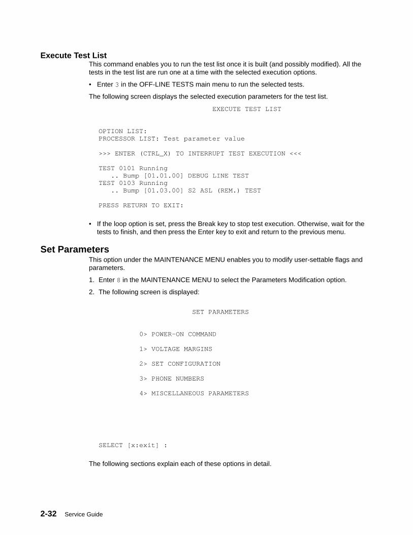
2-32 Service Guide
Execute Test ListThis command enables you to run the test list once it is built (and possibly modified). All thetests in the test list are run one at a time with the selected execution options.
• Enter 3 in the OFF-LINE TESTS main menu to run the selected tests.
The following screen displays the selected execution parameters for the test list.
EXECUTE TEST LIST
OPTION LIST: PROCESSOR LIST: Test parameter value
>>> ENTER (CTRL_X) TO INTERRUPT TEST EXECUTION <<<
TEST 0101 Running .. Bump [01.01.00] DEBUG LINE TESTTEST 0103 Running .. Bump [01.03.00] S2 ASL (REM.) TEST
PRESS RETURN TO EXIT:
• If the loop option is set, press the Break key to stop test execution. Otherwise, wait for thetests to finish, and then press the Enter key to exit and return to the previous menu.
Set ParametersThis option under the MAINTENANCE MENU enables you to modify user-settable flags andparameters.
1. Enter 8 in the MAINTENANCE MENU to select the Parameters Modification option.
2. The following screen is displayed:
SET PARAMETERS
0> POWER–ON COMMAND
1> VOLTAGE MARGINS
2> SET CONFIGURATION
3> PHONE NUMBERS
4> MISCELLANEOUS PARAMETERS
SELECT [x:exit] :
The following sections explain each of these options in detail.
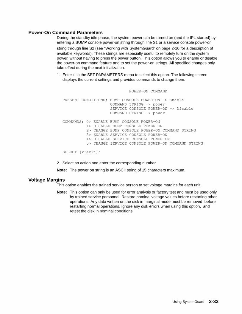
Using SystemGuard 2-33
Power-On Command ParametersDuring the standby idle phase, the system power can be turned on (and the IPL started) byentering a BUMP console power-on string through line S1 or a service console power-on
string through line S2 (see “Working with SystemGuard” on page 2-10 for a description ofavailable keywords). These strings are especially useful to remotely turn on the systempower, without having to press the power button. This option allows you to enable or disablethe power-on command feature and to set the power-on strings. All specified changes onlytake effect during the next initialization.
1. Enter 0 in the SET PARAMETERS menu to select this option. The following screendisplays the current settings and provides commands to change them.
POWER–ON COMMAND
PRESENT CONDITIONS: BUMP CONSOLE POWER–ON –> Enable COMMAND STRING –> power SERVICE CONSOLE POWER–ON –> Disable COMMAND STRING –> power
COMMANDS: 0> ENABLE BUMP CONSOLE POWER–ON 1> DISABLE BUMP CONSOLE POWER–ON 2> CHANGE BUMP CONSOLE POWER–ON COMMAND STRING 3> ENABLE SERVICE CONSOLE POWER–ON 4> DISABLE SERVICE CONSOLE POWER–ON 5> CHANGE SERVICE CONSOLE POWER–ON COMMAND STRING
SELECT [x:exit]:
2. Select an action and enter the corresponding number.
Note: The power on string is an ASCII string of 15 characters maximum.
Voltage MarginsThis option enables the trained service person to set voltage margins for each unit.
Note: This option can only be used for error analysis or factory test and must be used onlyby trained service personnel. Restore nominal voltage values before restarting otheroperations. Any data written on the disk in marginal mode must be removed beforerestarting normal operations. Ignore any disk errors when using this option, andretest the disk in nominal conditions.

2-34 Service Guide
Set ConfigurationThis command is used to configure electronic boards like I/O cards or Micro Channeladapter (MCA) devices.
1. Enter 2 in the SET PARAMETERS menu to display the SET CONFIGURATION menu asshown below:
SET CONFIGURATION
0> CPU CARD
1> MEMORY CARD
2> BASIC MCA ADAPTER
3> EXPANSION MCA ADAPTER
SELECT [x:exit]:
2. Select the card or adapter of your choice by entering the appropriate command number.A second-level screen lists available devices. For example, enter 2 to select MicroChannel adapter (MCA) devices and display a screen listing available adapters, similar tothe following:
BASIC MCA ADAPTER
0> BASIC MCA ADAPTER #0 1> BASIC MCA ADAPTER #4 2> BASIC MCA ADAPTER #5 3> BASIC MCA ADAPTER #6
SELECT [x:exit]:
3. Select the particular device which you want to configure. A third-level screen isdisplayed. For example, for adapter 0 (zero), you should see a screen similar to:
BASIC MCA ADAPTER #0
PRESENT CONDITIONS: Valid & Enable
COMMANDS: 0> BASIC MCA ADAPTER ENABLE 1> BASIC MCA ADAPTER DISABLE 2> BASIC MCA ADAPTER TEMPORARY DISABLE
SELECT [x:exit]:
4. Enter your choice in the SELECT field.
Phone NumbersThis command is used to set various service support phone numbers.
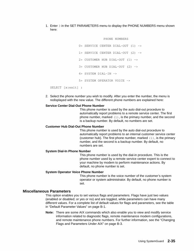
Using SystemGuard 2-35
1. Enter 3 in the SET PARAMETERS menu to display the PHONE NUMBERS menu shownhere:
PHONE NUMBERS
0> SERVICE CENTER DIAL–OUT (1) –>
1> SERVICE CENTER DIAL–OUT (2) –>
2> CUSTOMER HUB DIAL–OUT (1) –>
3> CUSTOMER HUB DIAL–OUT (2) –>
4> SYSTEM DIAL–IN –>
5> SYSTEM OPERATOR VOICE –>
SELECT [x:exit] :
2. Select the phone number you wish to modify. After you enter the number, the menu isredisplayed with the new value. The different phone numbers are explained here:
Service Center Dial-Out Phone NumberThis phone number is used by the auto dial-out procedure toautomatically report problems to a remote service center. The firstphone number, marked (1) , is the primary number, and the secondis a backup number. By default, no numbers are set.
Customer Hub Dial-Out Phone NumberThis phone number is used by the auto dial-out procedure toautomatically report problems to an internal customer service center(customer hub). The first phone number, marked (1) , is the primarynumber, and the second is a backup number. By default, nonumbers are set.
System Dial-In Phone NumberThis phone number is used by the dial-in procedure. This is thephone number used by a remote service center expert to connect toyour machine by modem to perform maintenance actions. Bydefault, no phone number is set.
System Operator Voice Phone NumberThis phone number is the voice number of the customer’s systemoperator or system administrator. By default, no phone number isset.
Miscellaneous ParametersThis option enables you to set various flags and parameters. Flags have just two values(enabled or disabled; or yes or no) and are toggled, while parameters can have manydifferent values. For a complete list of default values for flags and parameters, see the tablein “Default Parameter Values” on page B-1.
Note: There are some AIX commands which also enable you to view and modify serviceinformation related to diagnostic flags, remote maintenance modem configurations,and remote maintenance phone numbers. For further information, see the “ChangingFlags and Parameters Under AIX” on page B-3.
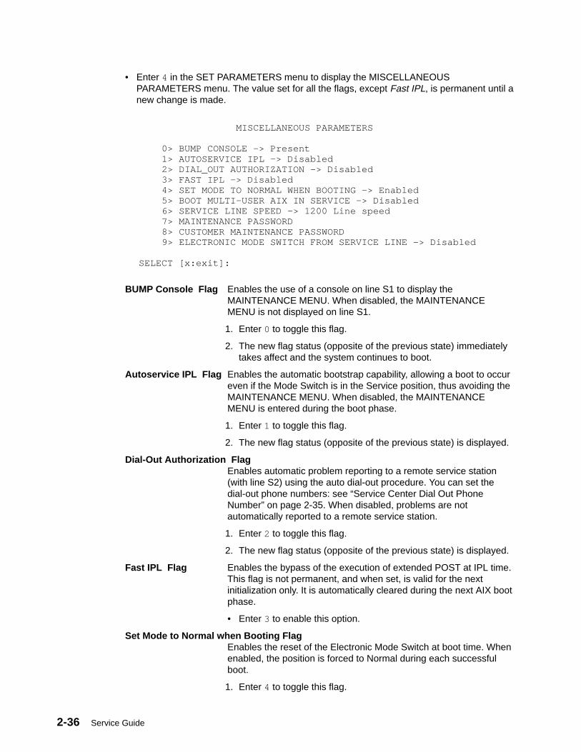
2-36 Service Guide
• Enter 4 in the SET PARAMETERS menu to display the MISCELLANEOUSPARAMETERS menu. The value set for all the flags, except Fast IPL, is permanent until anew change is made.
MISCELLANEOUS PARAMETERS
0> BUMP CONSOLE –> Present 1> AUTOSERVICE IPL –> Disabled 2> DIAL_OUT AUTHORIZATION –> Disabled 3> FAST IPL –> Disabled 4> SET MODE TO NORMAL WHEN BOOTING –> Enabled 5> BOOT MULTI–USER AIX IN SERVICE –> Disabled 6> SERVICE LINE SPEED –> 1200 Line speed 7> MAINTENANCE PASSWORD 8> CUSTOMER MAINTENANCE PASSWORD 9> ELECTRONIC MODE SWITCH FROM SERVICE LINE –> Disabled
SELECT [x:exit]:
BUMP Console Flag Enables the use of a console on line S1 to display theMAINTENANCE MENU. When disabled, the MAINTENANCEMENU is not displayed on line S1.
1. Enter 0 to toggle this flag.
2. The new flag status (opposite of the previous state) immediatelytakes affect and the system continues to boot.
Autoservice IPL Flag Enables the automatic bootstrap capability, allowing a boot to occureven if the Mode Switch is in the Service position, thus avoiding theMAINTENANCE MENU. When disabled, the MAINTENANCEMENU is entered during the boot phase.
1. Enter 1 to toggle this flag.
2. The new flag status (opposite of the previous state) is displayed.
Dial-Out Authorization FlagEnables automatic problem reporting to a remote service station(with line S2) using the auto dial-out procedure. You can set thedial-out phone numbers: see “Service Center Dial Out PhoneNumber” on page 2-35. When disabled, problems are notautomatically reported to a remote service station.
1. Enter 2 to toggle this flag.
2. The new flag status (opposite of the previous state) is displayed.
Fast IPL Flag Enables the bypass of the execution of extended POST at IPL time.This flag is not permanent, and when set, is valid for the nextinitialization only. It is automatically cleared during the next AIX bootphase.
• Enter 3 to enable this option.
Set Mode to Normal when Booting FlagEnables the reset of the Electronic Mode Switch at boot time. Whenenabled, the position is forced to Normal during each successfulboot.
1. Enter 4 to toggle this flag.
Using SystemGuard 2-37
2. The new flag status (opposite of the previous state) is displayed.
Boot Multiuser AIX In Service FlagEnables multiuser AIX boots to proceed even if the Mode Switch isin the Service position (when booting by selecting option 6 in theMAINTENANCE MENU). When the flag is enabled, the systemboots using the bootlist defined for a Normal boot (as when themode switch is set to Normal). When disabled and the mode switchis in the Service position, you cannot perform a muliti-user AIX boot.
1. Enter 5 to toggle this flag.
2. The new flag status (opposite of the previous state) is displayed.
Service Line Speed ParameterDefines the speed (baud rate) of the BUMP service line. The defaultis 1200.
1. Enter 6 to set this parameter. A menu showing possible linespeeds is displayed.
2. Select a baud rate and enter the corresponding menu number.
Maintenance PasswordThis command sets the maintenance password, which restrictsaccess to basic features. If you set this password, you should give itto service personnel when requested. By default, there is nopassword.
1. Enter 7 to set the maintenance password.
2. When requested, enter the password.
Customer Maintenance PasswordThis command sets the customer maintenance password, whichrestricts access to sensitive data such as: power on and power-offstrings; general and customer passwords; and most dial-in anddial-out phone numbers (except for the remote service center phonenumber). If you set this password, you normally should not give it toservice personnel. By default, there is no password.
1. Enter 8 to set the customer maintenance password.
2. When requested, enter the password.
Electronic Mode Switch from Service Line FlagEnables the modification of the Electronic Mode Switch through lineS2 (the remote maintenance line). When disabled, the ElectronicMode Switch can only be changed locally.
1. Enter 9 to toggle this flag.
2. The new flag status (opposite of the previous state) is displayed.
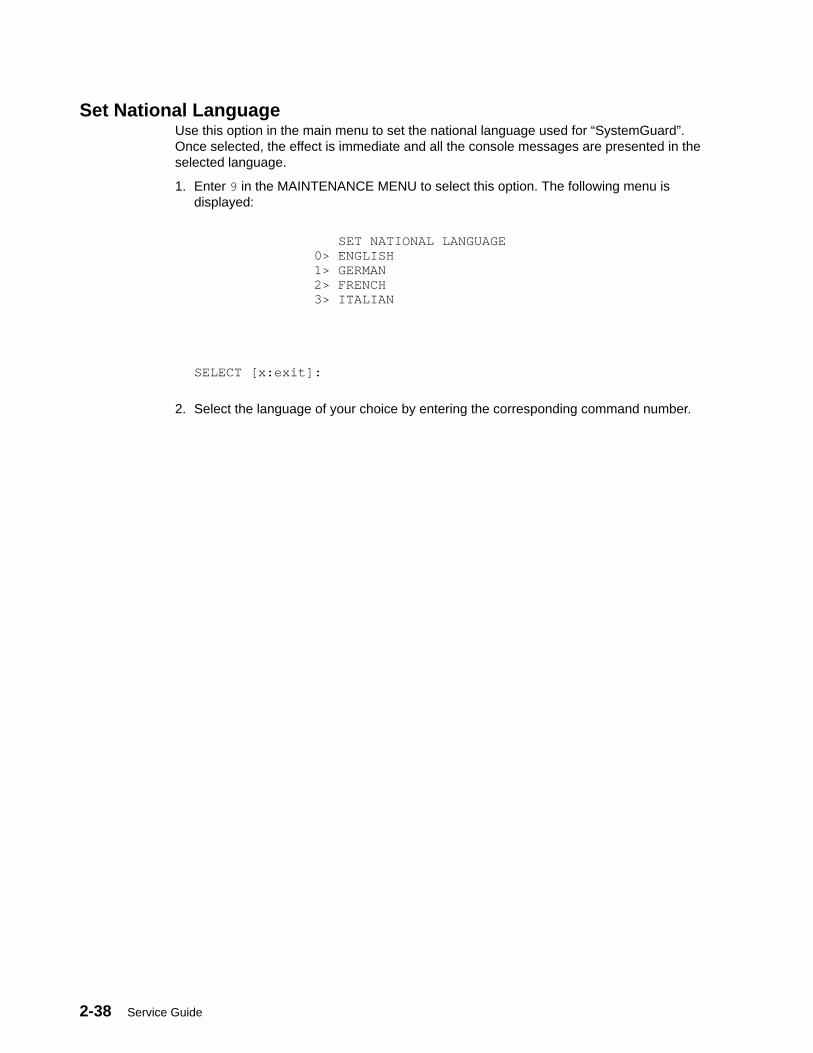
2-38 Service Guide
Set National LanguageUse this option in the main menu to set the national language used for “SystemGuard”.Once selected, the effect is immediate and all the console messages are presented in theselected language.
1. Enter 9 in the MAINTENANCE MENU to select this option. The following menu isdisplayed:
SET NATIONAL LANGUAGE 0> ENGLISH 1> GERMAN 2> FRENCH 3> ITALIAN SELECT [x:exit]:
2. Select the language of your choice by entering the corresponding command number.
Using SystemGuard 2-39
Some Common SystemGuard TasksThe following tasks are done through the STAND-BY and MAINTENANCE MENUs that arepart of SystemGuard. Note that these tasks can also be carried out from AIX diagnostics.
How to Set the Electronic KeyThe key can be set electronically, making it easier to provide remote support withoutphysically touching the machine. You can do this from the Stand-By mode or from AIX.
Setting the Electronic Key from Stand-By Mode1. Go into Stand-By mode.
2. Press the Enter key to get the prompt displayed (>).
3. Press the Enter key again. The cursor (in block mode) is then superimposed on top ofthe prompt.
4. At this point, press the Escape key and then the s key. This turns the Electronic Key toService even though the Physical Key is still in Normal position.
5. Press the Enter key again.
6. Enter the keyword, sbb (Stand-By BUMP). You should see the STAND-BY MENUappear; this is a way to check that the System Key is in Service.
7. Exit from the STAND-BY MENU.
At this step, if you want to go back to Normal, press the Enter key again; then press theESC-n key. This puts the Electronic Key to Normal position.
Setting the Electronic Key from AIX1. While AIX is running, log in as user root .
2. Type the following command to look at the current status of the Electronic Key:
keycfg –d
3. To change the key to Service, type the following command:
keycfg –c service
4. To change the key to Secure, type the following command:
keycfg –c secure
5. To change the key back to Normal, type the following command:
keycfg –c normal
Note that, each time, you can run the keycfg –d command to verify the status of the key.
Displaying Configuration through the Maintenance MenuThe system configuration can also be displayed through the MAINTENANCE MENU. Youwill find the same kind of information displayed previously, but in a different and morereadable way.
To get the system configuration from the MAINTENANCE MENU, do the following:
1. Enter the MAINTENANCE MENU.
2. Enter 0 to select DISPLAY CONFIGURATION .
The configuration display is a good picture of the SystemGuard configuration on one screen.Here is an example:
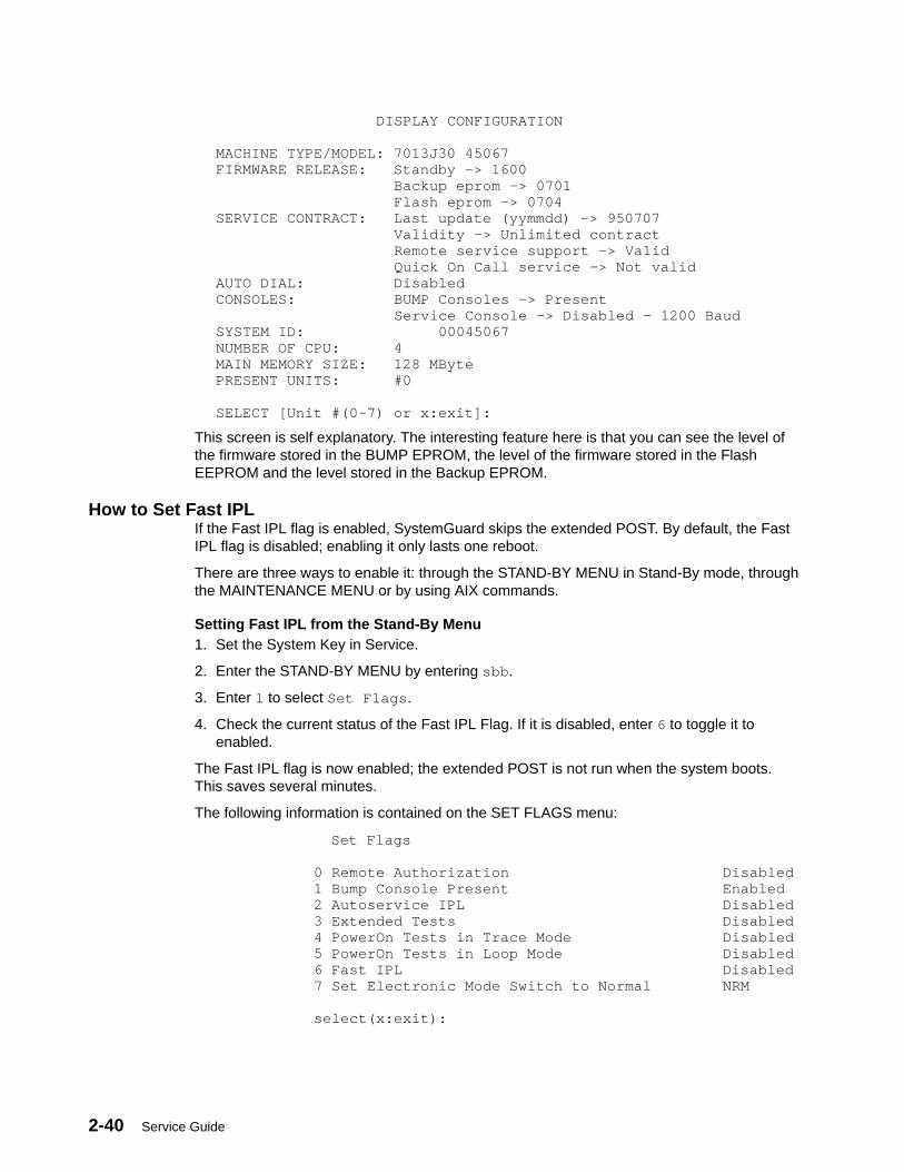
2-40 Service Guide
DISPLAY CONFIGURATION MACHINE TYPE/MODEL: 7013J30 45067FIRMWARE RELEASE: Standby –> 1600 Backup eprom –> 0701 Flash eprom –> 0704SERVICE CONTRACT: Last update (yymmdd) –> 950707 Validity –> Unlimited contract Remote service support –> Valid Quick On Call service –> Not validAUTO DIAL: DisabledCONSOLES: BUMP Consoles –> Present Service Console –> Disabled – 1200 BaudSYSTEM ID: 00045067NUMBER OF CPU: 4MAIN MEMORY SIZE: 128 MBytePRESENT UNITS: #0 SELECT [Unit #(0–7) or x:exit]:
This screen is self explanatory. The interesting feature here is that you can see the level ofthe firmware stored in the BUMP EPROM, the level of the firmware stored in the FlashEEPROM and the level stored in the Backup EPROM.
How to Set Fast IPLIf the Fast IPL flag is enabled, SystemGuard skips the extended POST. By default, the FastIPL flag is disabled; enabling it only lasts one reboot.
There are three ways to enable it: through the STAND-BY MENU in Stand-By mode, throughthe MAINTENANCE MENU or by using AIX commands.
Setting Fast IPL from the Stand-By Menu1. Set the System Key in Service.
2. Enter the STAND-BY MENU by entering sbb .
3. Enter 1 to select Set Flags .
4. Check the current status of the Fast IPL Flag. If it is disabled, enter 6 to toggle it toenabled.
The Fast IPL flag is now enabled; the extended POST is not run when the system boots.This saves several minutes.
The following information is contained on the SET FLAGS menu:
Set Flags
0 Remote Authorization Disabled 1 Bump Console Present Enabled 2 Autoservice IPL Disabled 3 Extended Tests Disabled 4 PowerOn Tests in Trace Mode Disabled 5 PowerOn Tests in Loop Mode Disabled 6 Fast IPL Disabled 7 Set Electronic Mode Switch to Normal NRM
select(x:exit):
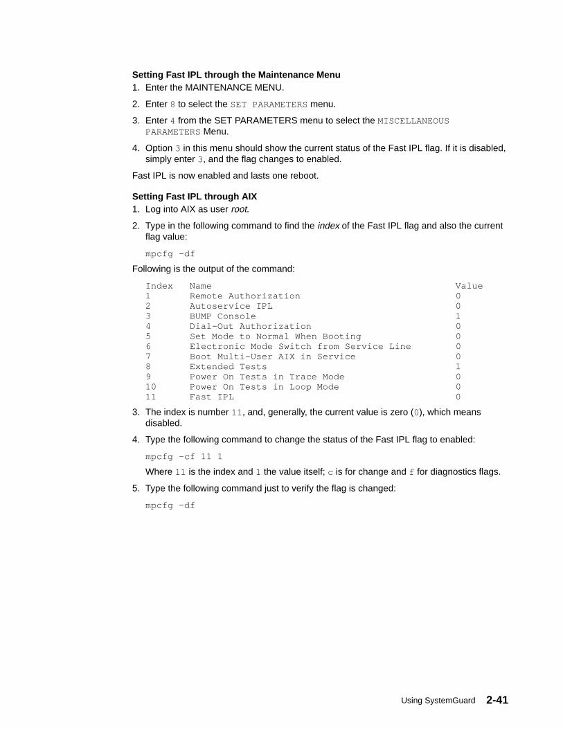
Using SystemGuard 2-41
Setting Fast IPL through the Maintenance Menu1. Enter the MAINTENANCE MENU.
2. Enter 8 to select the SET PARAMETERS menu.
3. Enter 4 from the SET PARAMETERS menu to select the MISCELLANEOUSPARAMETERS Menu.
4. Option 3 in this menu should show the current status of the Fast IPL flag. If it is disabled,simply enter 3, and the flag changes to enabled.
Fast IPL is now enabled and lasts one reboot.
Setting Fast IPL through AIX1. Log into AIX as user root.
2. Type in the following command to find the index of the Fast IPL flag and also the currentflag value:
mpcfg –df
Following is the output of the command:
Index Name Value1 Remote Authorization 02 Autoservice IPL 03 BUMP Console 14 Dial–Out Authorization 05 Set Mode to Normal When Booting 06 Electronic Mode Switch from Service Line 07 Boot Multi–User AIX in Service 08 Extended Tests 19 Power On Tests in Trace Mode 010 Power On Tests in Loop Mode 011 Fast IPL 0
3. The index is number 11 , and, generally, the current value is zero (0), which meansdisabled.
4. Type the following command to change the status of the Fast IPL flag to enabled:
mpcfg –cf 11 1
Where 11 is the index and 1 the value itself; c is for change and f for diagnostics flags.
5. Type the following command just to verify the flag is changed:
mpcfg –df
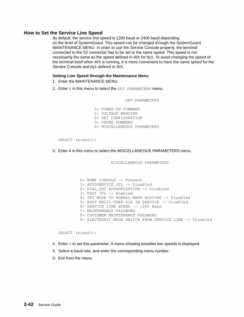
2-42 Service Guide
How to Set the Service Line SpeedBy default, the service line speed is 1200 baud or 2400 baud dependingon the level of SystemGuard. This speed can be changed through the SystemGuardMAINTENANCE MENU. In order to use the Service Console properly, the terminalconnected to the S2 connector has to be set to the same speed. This speed is notnecessarily the same as the speed defined in AIX for tty1. To avoid changing the speed ofthe terminal itself when AIX is running, it is more convenient to have the same speed for theService Console and tty1 defined in AIX.
Setting Line Speed through the Maintenance Menu1. Enter the MAINTENANCE MENU.
2. Enter 8 in this menu to select the SET PARAMETERS menu.
SET PARAMETERS 0> POWER–ON COMMAND 1> VOLTAGE MARGINS 2> SET CONFIGURATION 3> PHONE NUMBERS 4> MISCELLANEOUS PARAMETERS SELECT (x:exit):
3. Enter 4 in this menu to select the MISCELLANEOUS PARAMETERS menu.
MISCELLANEOUS PARAMETERS 0> BUMP CONSOLE –> Present 1> AUTOSERVICE IPL –> Disabled 2> DIAL_OUT AUTHORIZATION –> Disabled 3> FAST IPL –> Enabled 4> SET MODE TO NORMAL WHEN BOOTING –> Disabled 5> BOOT MULTI–USER AIX IN SERVICE –> Disabled 6> SERVICE LINE SPEED –> 1200 Baud 7> MAINTENANCE PASSWORD 8> CUSTOMER MAINTENANCE PASSWORD 9> ELECTRONIC MODE SWITCH FROM SERVICE LINE –> Disabled SELECT (x:exit):
4. Enter 6 to set this parameter. A menu showing possible line speeds is displayed.
5. Select a baud rate, and enter the corresponding menu number.
6. Exit from the menu.
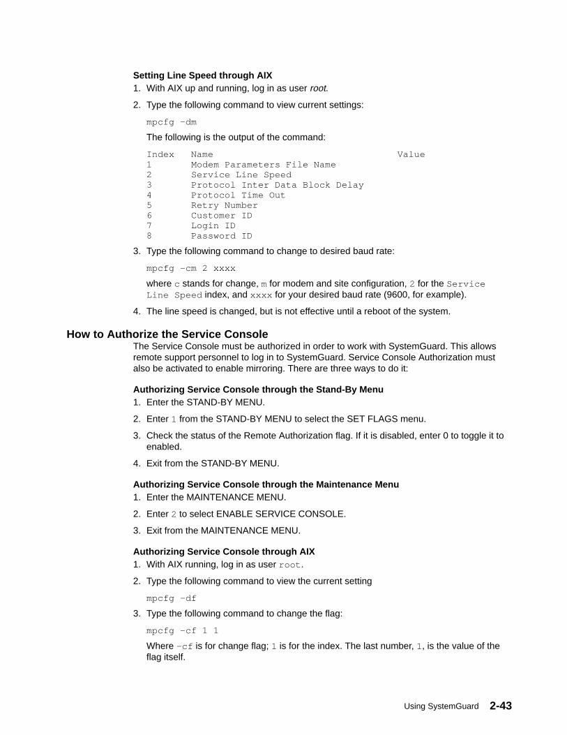
Using SystemGuard 2-43
Setting Line Speed through AIX1. With AIX up and running, log in as user root.
2. Type the following command to view current settings:
mpcfg –dm
The following is the output of the command:
Index Name Value1 Modem Parameters File Name2 Service Line Speed3 Protocol Inter Data Block Delay4 Protocol Time Out5 Retry Number6 Customer ID7 Login ID8 Password ID
3. Type the following command to change to desired baud rate:
mpcfg –cm 2 xxxx
where c stands for change, m for modem and site configuration, 2 for the ServiceLine Speed index, and xxxx for your desired baud rate (9600, for example).
4. The line speed is changed, but is not effective until a reboot of the system.
How to Authorize the Service ConsoleThe Service Console must be authorized in order to work with SystemGuard. This allowsremote support personnel to log in to SystemGuard. Service Console Authorization mustalso be activated to enable mirroring. There are three ways to do it:
Authorizing Service Console through the Stand-By Menu1. Enter the STAND-BY MENU.
2. Enter 1 from the STAND-BY MENU to select the SET FLAGS menu.
3. Check the status of the Remote Authorization flag. If it is disabled, enter 0 to toggle it toenabled.
4. Exit from the STAND-BY MENU.
Authorizing Service Console through the Maintenance Menu1. Enter the MAINTENANCE MENU.
2. Enter 2 to select ENABLE SERVICE CONSOLE.
3. Exit from the MAINTENANCE MENU.
Authorizing Service Console through AIX1. With AIX running, log in as user root .
2. Type the following command to view the current setting
mpcfg –df
3. Type the following command to change the flag:
mpcfg –cf 1 1
Where –cf is for change flag; 1 is for the index. The last number, 1, is the value of theflag itself.

2-44 Service Guide
How to Set Up Console MirroringConsole Mirroring ConceptsConsole mirroring is a way to provide the customer a view of what the person workingremotely from the Service Console is doing on the system. When mirroring is active, theService Console and the BUMP Console are logically identical, and both are tty0 (tty1 isdisabled when the mirroring starts).
Mirroring only works on the two serial ports, S1 and S2, and their respective ASCII consolesor terminal emulators. It does not work on the graphical devices. The BUMP Console can beeither local (no modem connected) or remote (through a modem connection). Remoteconsole connection must be established through dial-in (BUMP does not dial out). TheService Console is usually remote, connected through a Hayes-compatible modem on theS2 port; however a local, directly attached console at the S2 port can also be supported.
T
Modem
Customer Site
Remote Support Center
T
Modem
S1
S2System Unit
When mirroring is active, the customer on the BUMP Console and the support personnel onthe Service Console both see the same output on their screens, and either one may entercharacters. One person can even start typing and the other finish it. For example, thesupport personnel may log in as root on the Service Console, and the customer may enterthe root password on the BUMP Console. Therefore, the remote support personnel do notneed to know the root password.
Console mirroring is possible during the following SystemGuard phases: Stand-By, Init andRun-Time (AIX running).
The prerequisites for console mirroring are:
• Remote Service Support 1
• /usr/share/modems/mir_modem file present (for mirroring when AIX is up)
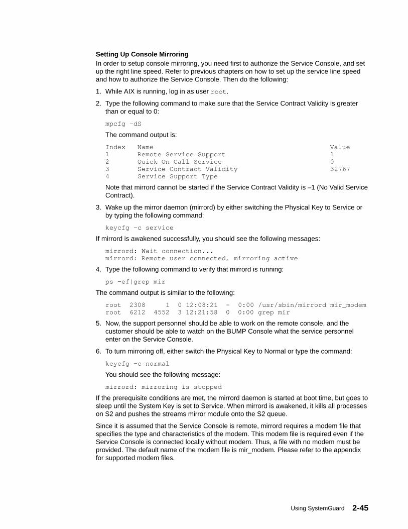
Using SystemGuard 2-45
Setting Up Console MirroringIn order to setup console mirroring, you need first to authorize the Service Console, and setup the right line speed. Refer to previous chapters on how to set up the service line speedand how to authorize the Service Console. Then do the following:
1. While AIX is running, log in as user root .
2. Type the following command to make sure that the Service Contract Validity is greaterthan or equal to 0:
mpcfg –dS
The command output is:
Index Name Value1 Remote Service Support 12 Quick On Call Service 03 Service Contract Validity 327674 Service Support Type
Note that mirrord cannot be started if the Service Contract Validity is –1 (No Valid ServiceContract).
3. Wake up the mirror daemon (mirrord) by either switching the Physical Key to Service orby typing the following command:
keycfg –c service
If mirrord is awakened successfully, you should see the following messages:
mirrord: Wait connection...mirrord: Remote user connected, mirroring active
4. Type the following command to verify that mirrord is running:
ps –ef|grep mir
The command output is similar to the following:
root 2308 1 0 12:08:21 – 0:00 /usr/sbin/mirrord mir_modemroot 6212 4552 3 12:21:58 0 0:00 grep mir
5. Now, the support personnel should be able to work on the remote console, and thecustomer should be able to watch on the BUMP Console what the service personnelenter on the Service Console.
6. To turn mirroring off, either switch the Physical Key to Normal or type the command:
keycfg –c normal
You should see the following message:
mirrord: mirroring is stopped
If the prerequisite conditions are met, the mirrord daemon is started at boot time, but goes tosleep until the System Key is set to Service. When mirrord is awakened, it kills all processeson S2 and pushes the streams mirror module onto the S2 queue.
Since it is assumed that the Service Console is remote, mirrord requires a modem file thatspecifies the type and characteristics of the modem. This modem file is required even if theService Console is connected locally without modem. Thus, a file with no modem must beprovided. The default name of the modem file is mir_modem. Please refer to the appendixfor supported modem files.
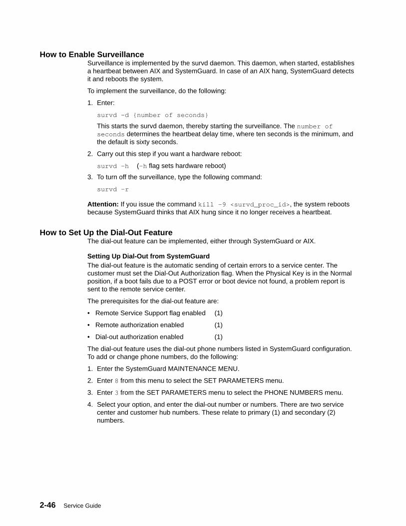
2-46 Service Guide
How to Enable SurveillanceSurveillance is implemented by the survd daemon. This daemon, when started, establishesa heartbeat between AIX and SystemGuard. In case of an AIX hang, SystemGuard detectsit and reboots the system.
To implement the surveillance, do the following:
1. Enter:
survd –d {number of seconds}
This starts the survd daemon, thereby starting the surveillance. The number ofseconds determines the heartbeat delay time, where ten seconds is the minimum, andthe default is sixty seconds.
2. Carry out this step if you want a hardware reboot:
survd –h (–h flag sets hardware reboot)
3. To turn off the surveillance, type the following command:
survd –r
Attention: If you issue the command kill –9 <survd_proc_id> , the system rebootsbecause SystemGuard thinks that AIX hung since it no longer receives a heartbeat.
How to Set Up the Dial-Out FeatureThe dial-out feature can be implemented, either through SystemGuard or AIX.
Setting Up Dial-Out from SystemGuardThe dial-out feature is the automatic sending of certain errors to a service center. Thecustomer must set the Dial-Out Authorization flag. When the Physical Key is in the Normalposition, if a boot fails due to a POST error or boot device not found, a problem report issent to the remote service center.
The prerequisites for the dial-out feature are:
• Remote Service Support flag enabled (1)
• Remote authorization enabled (1)
• Dial-out authorization enabled (1)
The dial-out feature uses the dial-out phone numbers listed in SystemGuard configuration.To add or change phone numbers, do the following:
1. Enter the SystemGuard MAINTENANCE MENU.
2. Enter 8 from this menu to select the SET PARAMETERS menu.
3. Enter 3 from the SET PARAMETERS menu to select the PHONE NUMBERS menu.
4. Select your option, and enter the dial-out number or numbers. There are two servicecenter and customer hub numbers. These relate to primary (1) and secondary (2)numbers.

Using SystemGuard 2-47
Modem ConfigurationThe modem on line S2 must be configured using an ASCII modem configuration file whichdescribes various parameters using a specific syntax. AIX uses this file directly.SystemGuard uses the same information (in condensed form) stored in non-volatile memory(NVRAM).
The modem line speed must be correctly set, either by using SystemGuard (see“Miscellaneous Parameters” on page 2-35 or the diag command. The modem configurationis used by both the dial-out and dial-in services.
The following table lists the data that SystemGuard sends to the remote support center.
Parameter Field Size Generated By
Magic Number 4 SystemGuard
Routing Metric 4 SystemGuard
Login ID 12 AIX Utility
CSS ID 4 SystemGuard
RETAIN Account Number 12 AIX Utility
General Password 16 AIX Utility
Time Stamp 8 SystemGuard
Customer System Phone 20 AIX Utility
Customer Operator Phone 20 AIX Utility
Machine Serial Number 10 SystemGuard or AIX Utility
Machine Device Type 13 SystemGuard or AIX Utility
Primary Error Code 4 SystemGuard
Destination 1 SystemGuard, HUB, or ServiceCenter
SRN LCD Code 64 SystemGuard
Text Problem Abstract 64 SystemGuard

2-48 Service Guide
How to Reboot AIX from the Remote Service ConsoleIt is possible for the remote personnel connected via the Service Console to reboot AIX fromthe remote site.
PrerequisitesThe following procedure must be carried out from the BUMP Console in order to allow AIX toboot remotely from the Service Console.
1. Get into the MAINTENANCE MENU (reboot the system with the key in Service mode).
2. Enter 8 in the MAINTENANCE MENU to select the SET PARAMETERS menu.
3. Enter 0 in the SET PARAMETERS menu to select the POWER-ON COMMAND menu.
4. Enter 3 and enable Service Console Power-On.
5. Enter 5 from the same menu, and enter the string power . This string is used forpowering-on the system from the Service Console.
6. Now reboot the system in Normal mode, and log in as user root.
7. Type the following commands:
mpcfg –cf 1 1 to enable Remote Authorization
mpcfg –cf 2 1 to enable Autoservice IPL
mpcfg –cf 6 1 to enable Electronic Mode Switch from S2
mpcfg –cf 7 1 to enable Boot Multi-User AIX in Service
mpcfg –cf 11 1 to enable Fast IPL
8. Type the following command to start console mirroring:
keycfg –c service
Now the system is set up so that the S2 port or the remote console can activate a reboot.The system can be rebooted either in AIX Multi-User or in Diagnostics to run diagnostics onthe hardware.
Rebooting to AIX Multi-User1. While AIX is running, log in as user root.
2. Type the command:
shutdown –F –t
and press Enter, to shut down the system.
You can use the –F flag for a fast shutdown and/or a –t flag for a shutdown at a particulartime.
3. Once the system has shut down press Enter, you should see the Stand-By prompt (>).
4. At this prompt, type sbb to get into the STAND-BY MENU.
5. Enter a 1 at the STAND-BY MENU to select the SET FLAGS menu.
6. Enter a 7 to select Set Electronic Mode Switch to Normal
7. Once the Electronic mode switch is set to Normal, exit out of the STAND-BY MENU untilyou have your prompt (>).
8. Type power at this prompt; the system should reboot.
9. You should get the AIX login prompt in about ten minutes.

Using SystemGuard 2-49
Rebooting to Single-User and then to Multi-UserThis allows the remote support personnel connected to the system via a modem to the S2port to shut down and reboot the system in Diagnostics mode for hardware diagnosticspurposes. After running diagnostics, the remote personnel can reboot the system in AIXMulti-User without having a need to physically touch the machine.
1. While AIX is running, type the command:
shutdown
and press Enter, to shut down the system.
2. Once the system is shutdown press Enter, you see the Stand-By mode prompt (>).Remember, at this point the Electronic switch is in Service mode. Leave it in Servicemode.
3. At the Stand-By prompt, type the power on keyword for S2 that we had set earlier(power in our example).
4. The system reboots in Diagnostics. From here, diagnostic tasks can be run.
5. Once completed, activate single-user boot from the Diagnostic’s main menu.
6. You are prompted for a password; enter the root password.
7. Type the following command to reboot in AIX Multi-User:
init 2
8. After about ten minutes, the system should have rebooted and loaded AIX.
9. If S2 was configured as a tty from AIX as well, an AIX login screen appears on thisremote Service Console.
How to Boot from a SCSI DeviceThe SMP server can be booted in Service mode from a desired SCSI device, either from theMAINTENANCE MENU or through the bootlist.
Booting from an SCSI Device through the Maintenance MenuWhen the system is booted with the system key in Service position, it either boots in theMAINTENANCE MENU, in Diagnostics or from a SCSI device, depending upon the variousflag settings.
Note: To be able to boot from an SCSI device other than the boot disk such as a tapedrive, the flag BOOT MULTI-USER AIX IN SERVICE must be disabled. This can beset through the MAINTENANCE MENU. To check or change this flag, do thefollowing:
1. Enter the MAINTENANCE MENU; refer to the MAINTENANCE MENU section on page2-21 for details.
2. From the MAINTENANCE MENU, enter 8 to select the SET PARAMETERS menu.
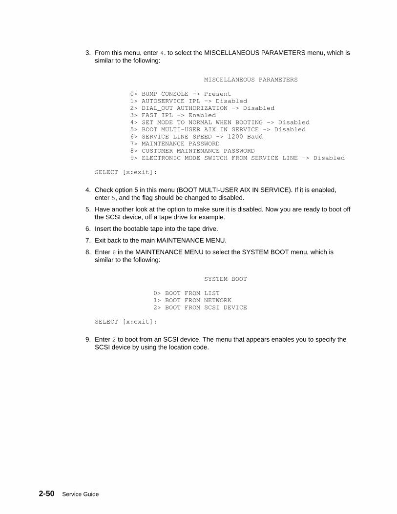
2-50 Service Guide
3. From this menu, enter 4. to select the MISCELLANEOUS PARAMETERS menu, which issimilar to the following:
MISCELLANEOUS PARAMETERS 0> BUMP CONSOLE –> Present 1> AUTOSERVICE IPL –> Disabled 2> DIAL_OUT AUTHORIZATION –> Disabled 3> FAST IPL –> Enabled 4> SET MODE TO NORMAL WHEN BOOTING –> Disabled 5> BOOT MULTI–USER AIX IN SERVICE –> Disabled 6> SERVICE LINE SPEED –> 1200 Baud 7> MAINTENANCE PASSWORD 8> CUSTOMER MAINTENANCE PASSWORD 9> ELECTRONIC MODE SWITCH FROM SERVICE LINE –> Disabled SELECT [x:exit]:
4. Check option 5 in this menu (BOOT MULTI-USER AIX IN SERVICE). If it is enabled,enter 5, and the flag should be changed to disabled.
5. Have another look at the option to make sure it is disabled. Now you are ready to boot offthe SCSI device, off a tape drive for example.
6. Insert the bootable tape into the tape drive.
7. Exit back to the main MAINTENANCE MENU.
8. Enter 6 in the MAINTENANCE MENU to select the SYSTEM BOOT menu, which issimilar to the following:
SYSTEM BOOT 0> BOOT FROM LIST 1> BOOT FROM NETWORK 2> BOOT FROM SCSI DEVICE SELECT [x:exit]:
9. Enter 2 to boot from an SCSI device. The menu that appears enables you to specify theSCSI device by using the location code.

Using SystemGuard 2-51
10.At this point, a BOOT FROM SCSI DEVICE screen appears. This displays the PRESENTDEVICE LOCATION CODE. If it is not the device you want to boot from, go through eachoption and change it to the desired BUS, SLOT, SCSI ID, and LUN ID. Option 4 allowsyou to change all these options at once. The BOOT FROM SCSI DEVICE screen issimilar to the following:
BOOT FROM SCSI DEVICE PRESENT DEVICE LOCATION CODE:(Drawer – Bus#/Slot# – Connector – SCSI ID/LUN) 000600600 COMMANDS: 0> CHANGE BUS# 1> CHANGE SLOT# 2> CHANGE SCSI ID 3> CHANGE LUN ID 4> CHANGE DEVICE LOCATION CODE 5> BOOT FROM SELECTED DEVICE SELECT [x:exit]: 5
See page 2-26 for descriptions of these fields.
11.Enter 5 to begin the boot. The system leaves the maintenance environment and bootsfrom the specified SCSI device.
Booting from an SCSI Device through the BootlistThe system can be booted from an SCSI device, such as a tape drive, without going throughthe MAINTENANCE MENU. In this case, it uses the bootlist to determine the boot devicewhile in Service mode. The bootlist can be updated through Service Aids in Diagnostics.
Following are the prerequisites for booting from an SCSI device (a tape drive for example) inService mode:
• The Autoservice IPL flag must be enabled.
• The Service mode bootlist must be updated (this can be done in AIX Diagnostics byselecting Service Aids and Display/Alter Bootlist).
• A supported SCSI device, such as a tape drive.
• A bootable SCSI media, such as a bootable tape (install or mksysb).
To boot off this SCSI device, do the following:
1. Switch the System Key to Service.
2. Insert the bootable media in the SCSI device.
3. Turn on the system power.
The system then boots up from this SCSI device. If the boot up is not successful, verify thatthe tape is bootable, or clean the media device.

2-52 Service Guide
How to Boot from the NetworkThe system can be booted from the network through the MAINTENANCE MENU. Networkboot allows a system to be reinstalled via the network and also allows various maintenancetasks to be carried out on the local machine. Use the following procedure to boot from thenetwork:
1. Enter the MAINTENANCE MENU.
2. From the MAINTENANCE MENU, enter 8 to select the SYSTEM BOOT menu, which issimilar to the following:
SYSTEM BOOT 0> BOOT FROM LIST 1> BOOT FROM NETWORK 2> BOOT FROM SCSI DEVICE SELECT [x:exit]: 1
3. From the SYSTEM BOOT menu, enter 1 to select BOOT FROM NETWORK, which issimilar to the following:
MAIN MENU 1. Select BOOT (Startup) Device2. Select Language for these Menus3. Send Test Transmission (PING)4. Exit Main Menu and Start System (BOOT) Type the number for your selection, then press ”ENTER”(Use the ”Backspace” key to correct errors)
4. From the NETWORK BOOT MAIN MENU, enter a 1 to select the Select BOOT (Startup)Device option.

Using SystemGuard 2-53
5. The SELECT BOOT (STARTUP) DEVICE menu appears, which is similar to thefollowing:
SELECT BOOT (STARTUP) DEVICE Select the device to BOOT (Startup) this machine. WARNING: If you are using Token–Ring, selection of anincorrect data rate can result in total disruption of theToken–Ring network.”==>” Shows the selected BOOT (startup) device ==> 1. Use Default Boot (Startup) Device 2. Token–Ring: Slot 3, 4 Mb data rate 3. Token–Ring: Slot 3, 16 Mb data rate 4. Ethernet: Slot 4, 15–pin connectorPage 1 of 2 88. Next Page of Select BOOT (Startup) Device Menu99. Return to Main Menu Type the number for your selection, then press ”ENTER”(Use the ”Backspace” key to correct errors)
6. Select the device to boot from. For example, choose 3 to boot from Token-Ring: slot 3,16 Mb data rate. A screen similar to the following appears:
SET OR CHANGE NETWORK ADDRESSES Select an address to changeCurrently selected BOOT (startup) device is: Token–Ring: Slot 2, 16 Mb data rateHardware address ................................ 10005AC97CF1 1. Client address 009.003.001.027 (address of this machine)2. BOOTP server address 009.003.001.008 (address of the remote machine you boot from)3. Gateway address 000.000.000.000 (Optional, required if gateway used) 97. Return to Select BOOT (Startup) Device Menu (SAVES addresses)99. Return to Main Menu (SAVES addresses) Type the number for your selection, then press ”ENTER”(Use the ”Backspace” key to correct errors)
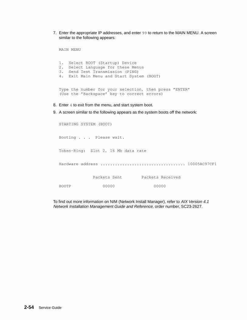
2-54 Service Guide
7. Enter the appropriate IP addresses, and enter 99 to return to the MAIN MENU. A screensimilar to the following appears:
MAIN MENU 1. Select BOOT (Startup) Device2. Select Language for these Menus3. Send Test Transmission (PING)4. Exit Main Menu and Start System (BOOT)
Type the number for your selection, then press ”ENTER”(Use the ”Backspace” key to correct errors)
8. Enter 4 to exit from the menu, and start system boot.
9. A screen similar to the following appears as the system boots off the network:
STARTING SYSTEM (BOOT) Booting . . . Please wait.
Token–Ring: Slot 2, 16 Mb data rate Hardware address ................................... 10005AC97CF1 Packets Sent Packets Received BOOTP 00000 00000
To find out more information on NIM (Network Install Manager), refer to AIX Version 4.1Network Installation Management Guide and Reference, order number, SC23-2627.
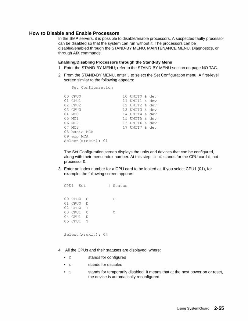
Using SystemGuard 2-55
How to Disable and Enable ProcessorsIn the SMP servers, it is possible to disable/enable processors. A suspected faulty processorcan be disabled so that the system can run without it. The processors can bedisabled/enabled through the STAND-BY MENU, MAINTENANCE MENU, Diagnostics, orthrough AIX commands.
Enabling/Disabling Processors through the Stand-By Menu1. Enter the STAND-BY MENU; refer to the STAND-BY MENU section on page NO TAG.
2. From the STAND-BY MENU, enter 3 to select the Set Configuration menu. A first-levelscreen similar to the following appears:
Set Configuration 00 CPU0 10 UNIT0 & dev01 CPU1 11 UNIT1 & dev02 CPU2 12 UNIT2 & dev03 CPU3 13 UNIT3 & dev04 MC0 14 UNIT4 & dev05 MC1 15 UNIT5 & dev06 MC2 16 UNIT6 & dev07 MC3 17 UNIT7 & dev08 basic MCA 09 exp MCASelect(x:exit): 01
The Set Configuration screen displays the units and devices that can be configured,along with their menu index number. At this step, CPU0 stands for the CPU card 0, notprocessor 0.
3. Enter an index number for a CPU card to be looked at. If you select CPU1 (01), forexample, the following screen appears:
CPU1 Set | Status 00 CPU0 C C01 CPU0 D02 CPU0 T03 CPU1 C C04 CPU1 D05 CPU1 T Select(x:exit): 04
4. All the CPUs and their statuses are displayed, where:
• C stands for configured
• D stands for disabled
• T stands for temporarily disabled. It means that at the next power on or reset,the device is automatically reconfigured.
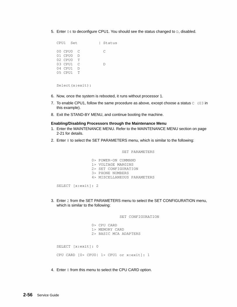
2-56 Service Guide
5. Enter 04 to deconfigure CPU1. You should see the status changed to D, disabled.
CPU1 Set | Status 00 CPU0 C C01 CPU0 D02 CPU0 T03 CPU1 C D04 CPU1 D05 CPU1 T Select(x:exit):
6. Now, once the system is rebooted, it runs without processor 1.
7. To enable CPU1, follow the same procedure as above, except choose a status C (03 inthis example).
8. Exit the STAND-BY MENU, and continue booting the machine.
Enabling/Disabling Processors through the Maintenance Menu1. Enter the MAINTENANCE MENU. Refer to the MAINTENANCE MENU section on page
2-21 for details.
2. Enter 8 to select the SET PARAMETERS menu, which is similar to the following:
SET PARAMETERS 0> POWER–ON COMMAND 1> VOLTAGE MARGINS 2> SET CONFIGURATION 3> PHONE NUMBERS 4> MISCELLANEOUS PARAMETERS SELECT [x:exit]: 2
3. Enter 2 from the SET PARAMETERS menu to select the SET CONFIGURATION menu,which is similar to the following:
SET CONFIGURATION 0> CPU CARD 1> MEMORY CARD 2> BASIC MCA ADAPTERS SELECT [x:exit]: 0 CPU CARD [0> CPU0| 1> CPU1 or x:exit]: 1
4. Enter 0 from this menu to select the CPU CARD option.
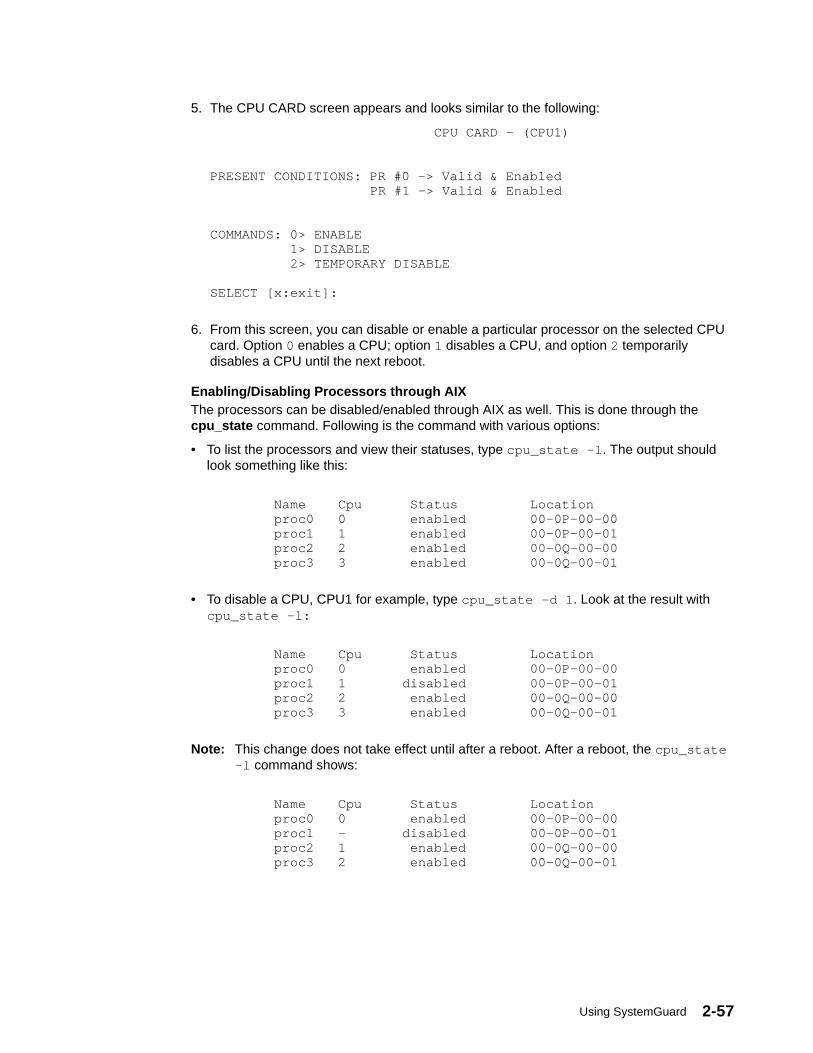
Using SystemGuard 2-57
5. The CPU CARD screen appears and looks similar to the following:
CPU CARD – (CPU1) PRESENT CONDITIONS: PR #0 –> Valid & Enabled PR #1 –> Valid & Enabled COMMANDS: 0> ENABLE 1> DISABLE 2> TEMPORARY DISABLE SELECT [x:exit]:
6. From this screen, you can disable or enable a particular processor on the selected CPUcard. Option 0 enables a CPU; option 1 disables a CPU, and option 2 temporarilydisables a CPU until the next reboot.
Enabling/Disabling Processors through AIXThe processors can be disabled/enabled through AIX as well. This is done through thecpu_state command. Following is the command with various options:
• To list the processors and view their statuses, type cpu_state –l . The output shouldlook something like this:
Name Cpu Status Location proc0 0 enabled 00–0P–00–00 proc1 1 enabled 00–0P–00–01 proc2 2 enabled 00–0Q–00–00 proc3 3 enabled 00–0Q–00–01
• To disable a CPU, CPU1 for example, type cpu_state –d 1 . Look at the result withcpu_state –l:
Name Cpu Status Location proc0 0 enabled 00–0P–00–00 proc1 1 disabled 00–0P–00–01 proc2 2 enabled 00–0Q–00–00 proc3 3 enabled 00–0Q–00–01
Note: This change does not take effect until after a reboot. After a reboot, the cpu_state–l command shows:
Name Cpu Status Location proc0 0 enabled 00–0P–00–00 proc1 – disabled 00–0P–00–01 proc2 1 enabled 00–0Q–00–00 proc3 2 enabled 00–0Q–00–01

2-58 Service Guide
Customizing SystemGuard For Your NeedsSystemGuard is controlled by several flags. The flags consist of Contract Flags, OperationalFlags, Remote Maintenance Flags, and Test Flags.
Remote Service FlagThis flag is disabled at the factory and must be enabled for remote service
Operational FlagsThe Operational Flags are the BUMP Console flag, the AutoService IPL flag, and Set Modeto Normal When Booting flag, which are enabled at the factory, however, they can becustomized for your needs.
The BUMP Console flag enables the SystemGuard Console attached to Serial Port 1. Ifenabled, the console attached to Serial Port 1 is shared with the operating system. It isrecommended that this flag always be enabled if a console is attached to Serial Port 1. Thisflag can be set from the Set Flags menu, MISCELLANEOUS PARAMETERS menu, or theService Aids.
The AutoService IPL flag instructs SystemGuard to bypass the MAINTENANCE MENUwhen the system is booted in Service Mode. This enables the system to be booted quickerwhen installing the operating system and when loading the diagnostics. It is recommendedthat this flag always be enabled unless there is a need to use the MAINTENANCE MENU.This flag can be set from the Set Flags menu, MISCELLANEOUS PARAMETERS menu, orthe Service Aids.
The Set Mode to Normal When Booting flag instructs SystemGuard to reset the ElectronicKey to Normal when booting. It is recommended that this flag always be enabled. This flagcan be set from the MISCELLANEOUS PARAMETERS menu or the Service Aids.
Test FlagsThe Test Flags are the Boot Multiuser AIX in Service flag, Fast IPL flag, Extended Tests flag,PowerOn Tests in Loop Mode flag, and PowerOn Tests in Trace Mode flag. They aredisabled at the factory. They are used during testing and do not need to be customized.
Remote Maintenance FlagsThe Remote Maintenance Flags are the Remote Authorization flag, Dial-Out Authorizationflag, and Electronic Mode Switch from Service Line flag. They are disabled at the factory,however, they can be customized for your needs.
The Remote Authorization flag enables the SystemGuard Console to use Serial Port 2 for aRemote Console and to report problems to a remote site. If enabled, Serial Port 2 is sharedwith the operating system. The setting of this flag depends if you are using remotemaintenance or not. This flag can be set from the Set Flags menu, MISCELLANEOUSPARAMETERS menu, or the Service Aids.
The Dial-Out Authorization flag enables the SystemGuard Console to report problems thatprevent the system from booting to be reported to a remote site via Serial Port 2. The settingof this flag depends if you are using remote maintenance or not and if you want problemsthat prevent the system from booting to be reported to a remote site. This flag can be setfrom the Set Flags menu, MISCELLANEOUS PARAMETERS menu, or the Service Aids. Ifthis flag is enabled, a Service Center Dial-Out phone number must be set.
The Electronic Mode Switch from Service Line flag enables the Electronic Mode Switch tobe controlled from the Service Console. The setting of this flag depends if you want theElectronic Mode Switch to be controlled from the Service Line or not. This flag can be setfrom the MISCELLANEOUS PARAMETERS menu or the Service Aids.
Using SystemGuard 2-59
Phone NumbersIf remote maintenance is used, SystemGuard requires several phone numbers to beentered. Additional information is provided in “Phone Numbers” on page 2-34.
Service Line Speed ParametersIf remote maintenance is used, SystemGuard requires that the line speed be configured.The default is 1200 baud. The speed can be set by MISCELLANEOUS PARAMETERSmenu or the Service Aids.
Modem ParametersIf remote maintenance is used, SystemGuard may require that the Modem Parameters filebe updated. This file can be set by the Service Aids.
PasswordsPasswords are used to protect access to SystemGuard. The passwords are theMaintenance Password and the Customer Maintenance Password. No passwords are set atthe factory. However, they can be customized for your needs. The Maintenance Passwordrestricts access to basic features of the MAINTENANCE MENU. If you set the password youshould provide it to your service personnel when requested. The Customer MaintenancePassword restricts access to sensitive customer data. If you set the password you normallyshould not provide it to your service personnel. The passwords can be set from theMISCELLANEOUS PARAMETERS menu.
2-60 Service Guide
Reloading the Flash EEPROMFollow this procedure to load a new version of SystemGuard into the flash EEPROM. Onlysystem administrators should perform this procedure.
PrerequisitesTo install a new version of the EEPROM firmware, you need either a firmware diskettecontaining a binary firmware image, or a file containing the firmware.
You can also update the firmware using a file containing a new firmware version.
Updating the Flash EEPROM (using a firmware diskette)If the system is not yet powered on, simply insert the firmware diskette in the drive, place theMode Switch in the Service position, and then power on the system. The firmware diskette isidentified by a special header which distinguishes it from diskettes containing other data.The existing firmware recognizes the special header and automatically loads the newfirmware version.
If AIX is already up and running (the run-time phase), reloading the firmware requires moresteps, because you first have to shut down the system, then reboot the machine asdescribed in the preceding paragraph.
Updating the Flash EEPROM (using a file)An administrator with root authority can use the AIX diag command to update the EEPROMfirmware using a file. Because this procedure reboots the machine after the update, the rootuser who performs this procedure should be the only logged user. If the system is not yetpowered on, power on the system, and log in as the root user without letting other users login. Then follow the steps to use when the system is up and running.
If AIX is already up and running (the run-time phase), perform the following steps:
1. Make sure that no other users are logged in to the system (log them out if necessary).
2. Make sure that you have root authority (use the su command if necessary).
3. Enter the diag command or load diagnostics when the Key Mode switch is in theService position.
4. Select Service Aids.
5. Select the BUMP Service Aids option.
6. Select the Flash Eprom Download option.
7. Enter the full path name for the file containing the new flash EEPROM image. The imagefile installed with the operating system is located in the /usr/lpp/devices.base directory.
8. The system is automatically rebooted.
3-1520-1Maintenance Analysis Procedures (MAPs)
Chapter 3. Maintenance Analysis Procedures (MAPs)
MAP 1520: 7013 J Series Power MAPNote: This is not a start of call MAP. Use this Power MAP only if you have been directed
here from a MAP step in the Diagnostic Information For Micro Channel BusSystems.
This procedure is used to locate power problems in 7013 J Series. If a problem is detected,this procedure helps you to isolate the problem to the failing unit, which can be replacedwith a field-replaceable unit (FRU).
Note: If you need more detailed information about the Power/Keylock Status Register(PKSR) bit definitions when using this map, see Error Logging, on page D-26. Adetailed description of the system power states can be found in “Appendix F. SystemPower States.”
Observe the following safety notice during service procedures.
Note: For a translation of these notices, see System Unit Safety Information.
DANGERAn electrical outlet that is not correctly wired could place hazardous voltageon metal parts of the system or the products that attach to the system. It isthe responsibility of the customer to ensure that the outlet is correctly wiredand grounded to prevent an electrical shock.
Before installing or removing signal cables, ensure that the unit main switch isset to off or the power cable is unplugged for the system unit and all attacheddevices are unplugged.
When adding or removing any additional external devices to or from the system,ensure that the power cables for those devices are unplugged before the signalcables are connected. If possible, disconnect all power cables from the existingsystem before you add a device.
Use one hand, when possible, to connect or disconnect signal cables to preventa possible shock from touching two surfaces with different electrical potentials.
During an electrical storm, do not connect cables for display stations, printers,telephones, or station protectors for communication lines.
CAUTION:This product is equipped with a 3-wire power cable and plug for the user’s safety.Use this power cable in conjunction with a properly grounded electrical outlet toavoid electrical shock.

3-1520-2 Service Guide
Power Supply StatusIn 7013 J Series models, if the system detects a power supply failure on the base unit orMCA expansion unit, it turns the power off and displays service-request number (SRN)409-Axy , where xy is the hexadecimal value of the power status register and gives someinformation on the power fault, as described in this MAP.
If the power fault condition occurs on the disk expansion unit, while the system is running,the system may detect the fault and log the error; however, if a reboot is launched, thesystem will recognize the power fault and display 409-Axy SRN.
Line two of the operator panel display identifies the unit that contains the error. Units arenumbered as:
0 Base System unit
1 Expansion unit
Step 1You may be directed to this MAP for several reasons:
1. SRN 409-Axy appears on the operator panel display: a power fault has been detectedon some unit and the entire system has been powered off.
Go to Step 10.
2. The power button has been pressed (set to on), but the power does not stay on; noinformation remains displayed on the operator panel display.
Go to step 2.
3. SRN 409-098 appears on the operator panel display. This SRN indicates that the unittop cover is not correctly closed or that the top cover switch is defective. Check if the topcover is correctly closed and, if it is not, close it properly, following the proceduredescribed earlier in this guide; otherwise, call your service support person for assistance.
Step 2(from Step 1)
1. Set the power button on the system unit to Off.
2. Set the system unit main switch to Off.
3. Set the key mode switch to the Service position.
4. Set the system unit main switch to On.
Is anything (even a blinking cursor) displayed in the operator panel display?
NO Go to Step 3
YES Go to Step 8
3-1520-3Maintenance Analysis Procedures (MAPs)
Step 3(from Step 2)
Is the operator panel display illuminated?
NO Go to Step 4
YES Go to Step 7
Step 4(from Step 3)
1. Follow the removal procedure under “Rear Cover” on page 4-4 in 7013 J Series ServiceGuide.
2. Check the LED on the System Interface Board. If the LED is on, it means that the powersupply unit supplies the Stand-By voltages.
Is the System Interface Board LED on?
NO Go to Step 5
YES Go to Step 7
Step 5(from Step 4)
1. Set the system unit main switch to Off.
2. Be sure that the external power cable to the system unit has continuity.
3. Be sure that the external power cable is plugged into both the system unit and the poweroutlet.
4. Be sure that the power outlet has been wired correctly with the correct voltage.
5. Check if the power cable is correctly connected to the Power Supply. Follow the removalprocedure under “Front Cover” on page 4-7 in 7013 J Series Service Guide.
Did you find a problem?
NO Go to Step 6.
YES Correct the problem. Go to “Map 0410: Repair Checkout” in the DiagnosticInformation For Micro Channel Bus Systems
3-1520-4 Service Guide
Step 6(from Step 5)
Note: Either the Power Supply module (90 % failure probability) or the Back Plane (10 %failure probability) is defective.
1. Set the system unit main switch to Off.
2. Replace the power supply. Refer to “Power Supply” on page 4-50 in 7013 J SeriesService Guide.
3. Set the system unit main switch to On.
Has the symptom changed?
NO Reinstall the original Power Supply.
Repeat Step 6, exchanging the back plane. Refer to “Back Plane” on page4-95 in 7013 J Series Service Guide.
If you exchanged both Power Supply and Back Plane, call your servicesupport person for assistance.
YES Go to “Map 0410: Repair Checkout” in the Diagnostic Information For MicroChannel Bus Systems.
Step 7(from Steps 3 and 4)
Note: Either the operator panel (99 % failure probability) or the back plane (1 % failureprobability) unit is defective.
1. Set the power button on the system unit to Off.
2. Set the system unit main switch to Off.
3. Exchange the operator panel. Refer to “Operator Panel” on page 4-26 in 7013 J SeriesService Guide.
4. Set the key mode switch to the Service position.
5. Set the system unit main switch on the system unit to On.
Has the symptom changed?
NO Reinstall the original operator panel.
Repeat Step 7, exchanging the back plane. Refer to “Back Plane” on page4-95 in 7013 J Series Service Guide.
If you exchanged both operator panel and back plane, call your servicesupport person for assistance.
YES Go to “Map 0410: Repair Checkout” in the Diagnostic Information For MicroChannel Bus Systems.
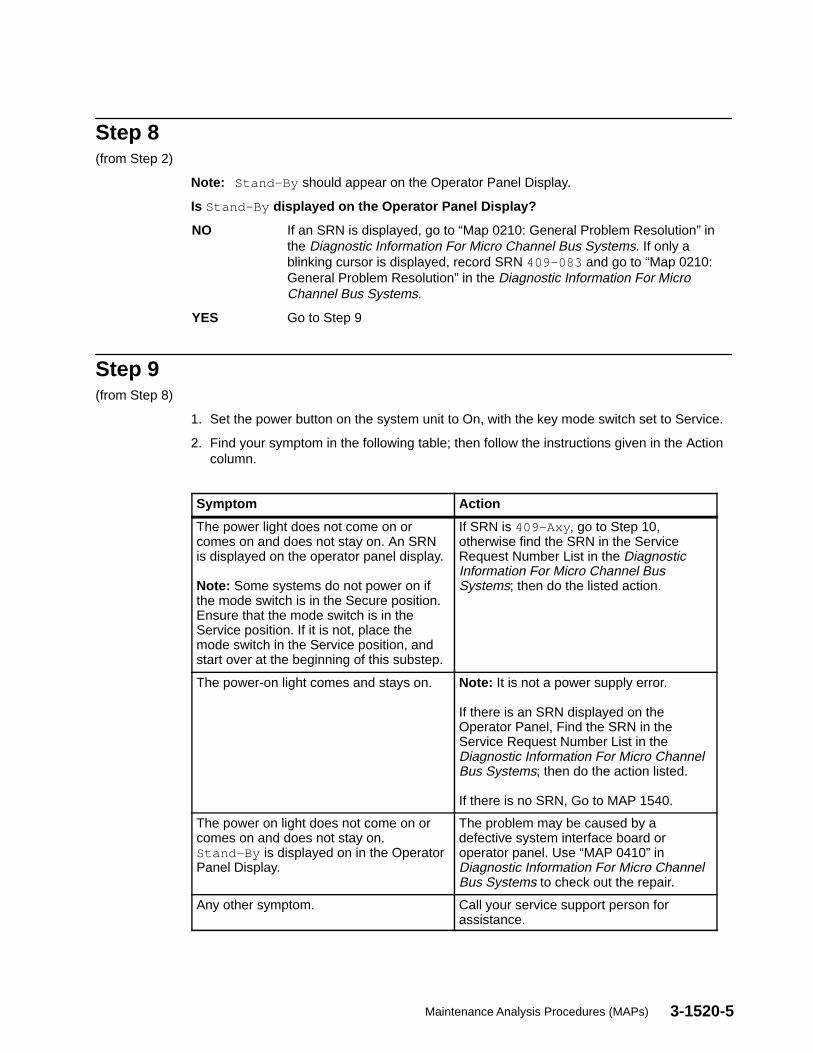
3-1520-5Maintenance Analysis Procedures (MAPs)
Step 8(from Step 2)
Note: Stand-By should appear on the Operator Panel Display.
Is Stand-By displayed on the Operator Panel Display?
NO If an SRN is displayed, go to “Map 0210: General Problem Resolution” inthe Diagnostic Information For Micro Channel Bus Systems. If only ablinking cursor is displayed, record SRN 409-083 and go to “Map 0210:General Problem Resolution” in the Diagnostic Information For MicroChannel Bus Systems.
YES Go to Step 9
Step 9(from Step 8)
1. Set the power button on the system unit to On, with the key mode switch set to Service.
2. Find your symptom in the following table; then follow the instructions given in the Actioncolumn.
Symptom Action
The power light does not come on orcomes on and does not stay on. An SRNis displayed on the operator panel display.
Note: Some systems do not power on ifthe mode switch is in the Secure position.Ensure that the mode switch is in theService position. If it is not, place themode switch in the Service position, andstart over at the beginning of this substep.
If SRN is 409-Axy , go to Step 10,otherwise find the SRN in the ServiceRequest Number List in the DiagnosticInformation For Micro Channel BusSystems; then do the listed action.
The power-on light comes and stays on. Note: It is not a power supply error.
If there is an SRN displayed on theOperator Panel, Find the SRN in theService Request Number List in theDiagnostic Information For Micro ChannelBus Systems; then do the action listed.
If there is no SRN, Go to MAP 1540.
The power on light does not come on orcomes on and does not stay on.Stand-By is displayed on in the OperatorPanel Display.
The problem may be caused by adefective system interface board oroperator panel. Use “MAP 0410” inDiagnostic Information For Micro ChannelBus Systems to check out the repair.
Any other symptom. Call your service support person forassistance.
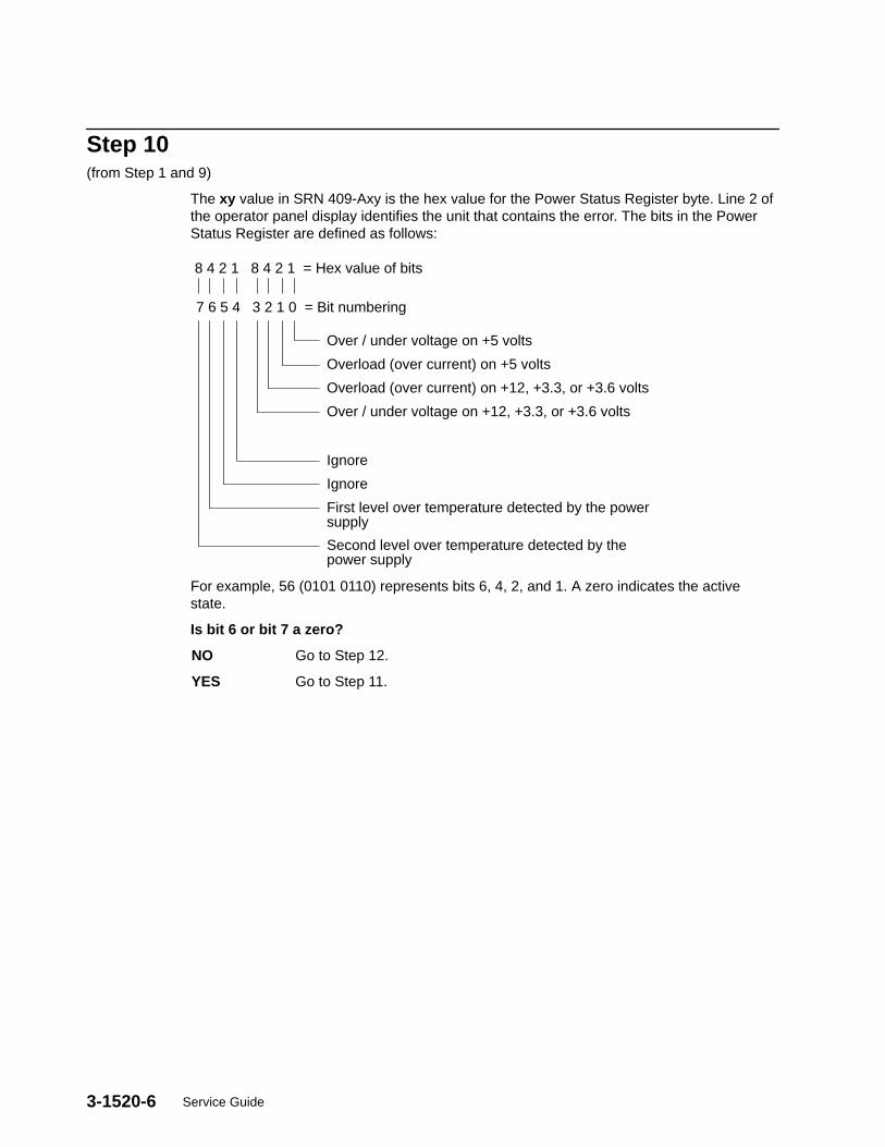
3-1520-6 Service Guide
Step 10(from Step 1 and 9)
The xy value in SRN 409-Axy is the hex value for the Power Status Register byte. Line 2 ofthe operator panel display identifies the unit that contains the error. The bits in the PowerStatus Register are defined as follows:
8 4 2 1 8 4 2 1 = Hex value of bits
7 6 5 4 3 2 1 0 = Bit numbering
Over / under voltage on +5 volts
Overload (over current) on +5 volts
Overload (over current) on +12, +3.3, or +3.6 volts
Over / under voltage on +12, +3.3, or +3.6 volts
Ignore
Ignore
First level over temperature detected by the powersupply
Second level over temperature detected by thepower supply
For example, 56 (0101 0110) represents bits 6, 4, 2, and 1. A zero indicates the activestate.
Is bit 6 or bit 7 a zero?
NO Go to Step 12.
YES Go to Step 11.
3-1520-7Maintenance Analysis Procedures (MAPs)
Step 11(from Step 10)
An over temperature problem can be caused by an environmental problem (seeSpecifications on page 1-41 in 7013 J Series Service Guide), blocked air ducts, or a cloggedair filter. Check each of these items.
Did you find the problem?
NO Go to Step 12.
YES Repair the problem. Go to “Map 0410: Repair Checkout” in the DiagnosticInformation For Micro Channel Bus Systems.
Step 12(from Steps 10 and 11)
Is bit 1 or bit 2 a zero?
NO Replace the power supply.
If the symptom did not change, reinstall the original power supply. Call yourservice support person for assistance.
Go to “Map 0410: Repair Checkout” in the Diagnostic Information For MicroChannel Bus Systems.
YES Go to “MAP 1540: 7013 J Series System Unit – Minimum Configuration” onpage 3-1540-1.

3-1520-8 Service Guide
3-1540-1Maintenance Analysis Procedures (MAPs)
MAP 1540: 7013 J Series System Unit - Minimum ConfigurationNote: This is not a start of call MAP. You should use this MAP only if you have been
directed here from a MAP step in the Diagnostic Information For Micro Channel BusSystems.
Purpose of this MAPThis MAP is used to locate defective FRUs not found by normal diagnostics. For thisprocedure, diagnostics are run on a minimum-configured system. If a failure is detected onthe minimum-configured system, the remaining FRUs are exchanged one at a time until thefailing one is identified. If a failure is not detected, FRUs are added back until the failureoccurs. The failure is then isolated to the failing FRU.
The MAP steps on the following pages instruct you to reduce the system to one or more ofthe following configurations:
Notes:
Install the memory cards in a right-to-left sequence beginning with slot A, and thencontinuing with slots B, C, and D. Memory cards must be installed with no emptyslots between installed memory cards.
Install the CPU cards in a right-to-left sequence beginning with slot P, and thencontinuing with slots Q, R, and S. CPU cards must be installed with no empty slotsbetween installed CPU cards.
– Back Plane, system planar (SP), MCA planar (MP), I/O card (IOC), FXB/FXE flexcable, system interface board (SIB), operator panel, one CPU card (CPU), onememory card (MC), and power supply (PS).
If no failure is detected, the maintenance menu is displayed. Any other responsemeans one of the remaining FRUs is failing.
– Back Plane, system planar (SP), MCA planar (MP), I/O card (IOC), FXB/FXE flexcable, system interface board (SIB), operator panel, one CPU card (CPU), onememory card (MC), power supply (PS), CD-ROM drive, SCSI adapter, and a systemconsole attached to the S1 port.
If no failure is detected, the Diagnostic Operating Instructions frame is displayed whenthe diagnostics are loaded, and the system console is selected. Any other responsemeans one of the remaining FRUs is failing.

3-1540-2 Service Guide
Step 1(from Steps 3, 6, 7, 9, 10, 11)
1. Ensure that the diagnostics and the operating system are shut down.
2. Turn the key mode switch to the Service Position.
3. Sometimes an SRN or Error Code will be logged in the BUMP Error Log. Beforeproceeding, check the BUMP Error Log for any SRNs or Error Codes. This is done asfollows:
a. Power off.
b. Enable the BUMP Console Flag and disable the Autoservice IPL flag. This is done asfollows:
– Press Enter.
– Type sbb and press Enter.
– Select Set Flags .
Note: Ensure BUMP console is enabled and Autoservice is disabled.
– Exit the Standby menu.
c. Power on.
d. When the Maintenance Menu appears, display the Bump Error Log.
e. If an SRN is logged, record it and any location codes. Location Codes are separatedby a blank. Perform the listed action. An SRN will be preceded by 888 103.
f. If no SRN is logged, check for an Error Code. If an Error Code is logged, record itand any location code. Location codes are separated by a blank. Perform the listedaction. Look up the Error Code for possible FRUs.
g. If nothing is logged, proceed to the next substep.
4. Set the power button on the system unit to Off.
5. Set the main power switch on the system unit to Off.
6. Set the main power switch on the system unit to On.
7. Set the power button on the system unit to On.
8. Insert the diagnostic CD-ROM disc into the CD-ROM drive.
9. Find the symptom in the following table that best matches the symptom on your system,and then perform the associated task.

3-1540-3Maintenance Analysis Procedures (MAPs)
Note: Before verifying any condition indicated in the following steps of this MAP (forexample, a certain code displayed on the operator panel display), be sure that thesystem activity has stopped on that condition (same condition for more than 3minutes except for 165 , which may display up to ten minutes with no activity on theBUMP console).
Information inoperator paneldisplay
Other conditions Do this:
Blank Diagnostic Operating Screen is displayed. Go to Step 10.
Blank Maintenance Menu is displayed. Select System Boot ,then Boot From List . Wait for one of the othersymptoms in this table tooccur.
888 flashing With same SRN or a Crash Code Go to Step 2.
888 flashing With new SRN Record the SRN. Look upthe SRN in the SRN Tableand do the listed action.
260 Main Menu is Displayed Select Exit Main Menuand Start System(Boot) then press En-ter.When the StartingSystem Boot menu dis-plays, press Enter.Note: Repeat this pro-cedure each time theseconditions occur.
269 flashing Go to Step 20.
269 solid Go to Step 19.
c31 Instructions to select the system consoleare displayed on the screen.
Follow the instructions onthe screen. Wait for oneof the other symptoms inthis table to occur.
325 or less Digits are on solid for more than 3 minutes,except for 165 which may display up to tenminutes with no activity on the BUMP con-sole, and the Power light is on.
Go to Step 2.
326 or greater Digits are on solid for more than 3 minutes,the Power light is on, and the diagnosticCD is loaded.
Go to Step 7.
Any symptom not listed above. Go to Step 2.
3-1540-4 Service Guide
Step 2(from Step 1)
1. Set the power button on the system unit to Off.
2. Set the main power switch on the back of the system unit to Off.
3. Record the slot numbers of the adapters. Label and record the location of any cablesattached to the adapters. Remove all the MCA adapters.
4. Record the slot numbers of the memory cards (MC), and then remove all the memorycards (MC), except the one in slot A.
5. Record the slot numbers of the CPU cards (CPU) and then remove all the CPU cards(CPU), except the one in slot P.
6. Set the main power switch on the back of the system unit to On.
7. Set the power button on the system unit to On.
8. Wait for one of the following conditions to occur:
• The Maintenance Menu is displayed.
• The same three digit number is displayed in the operator panel display for longer thanthree minutes except for 165 , which may display up to ten minutes with no activity onthe BUMP console
• The number 888 is flashing in the operator panel display.
Is the maintenance menu displayed?
NO Go to Step 3.
YES If a CPU or memory card was removed, go to Step 4. Otherwise, power offthe system, unplug the power cable and do the following actions:
• Install the SCSI adapter.
• Connect the SCSI cable from the SCSI adapter to the SCSI connectorlocated above the disk drive.
• Go to Step 7, substep 5.
3-1540-5Maintenance Analysis Procedures (MAPs)
Step 3(from Step 2)
One of the FRUs remaining in the system unit is defective.
To test each FRU, exchange the FRUs that have not already been exchanged in thefollowing order:
1. I/O card (IOC)
2. CPU card (CPU)
3. Memory card (MC)
4. System planar (SP)
5. MCA planar (MP)
6. Power supply (PS)
7. FXB/FXE flex cable
8. System interface board (SIB)
9. Operator panel
10.Back plane
The system is working correctly if the maintenance menu is displayed. If this occurs, the lastpart you exchanged is defective.
1. Set the power button on the system unit to Off.
2. Exchange one of the FRUs in the list.
3. Set the power button on the system unit to On.
4. Wait for one of the following conditions to occur:
• The Maintenance Menu is displayed.
• The same three digit number is displayed in the operator panel display for longer thanthree minutes except for 165 , which may display up to ten minutes with no activity onthe BUMP console
• The number 888 is flashing in the operator panel display.
Is the maintenance menu displayed?
NO Reinstall the original part.
Repeat Step 3 until the defective FRU is identified or all the FRUs havebeen exchanged.
If the symptom did not change and all the FRUs have been exchanged, callyour service support person for assistance.
If the symptom has changed, check for loose cards, cables, and obviousproblems. If you do not find a problem, return to Step 1 in this MAP andfollow the instructions for the new symptom.
YES The last FRU you exchanged is the defective one. Reinstall all the FRUsyou have exchanged, except the last one and power on the system. Go to“Map 0410: Repair Checkout” in the Diagnostic Information For MicroChannel Bus Systems.

3-1540-6 Service Guide
Step 4(from Step 2)
No failure was detected with this configuration.
1. Set the power button on the system unit to Off.
2. Set the main power switch on the system unit to Off.
3. Starting with the CPU cards, install one additional CPU card (CPU) or memory card(MC) (if any).
4. Set the main power switch on the system unit to On.
5. Set the power button on the system unit to On.
6. Wait for one of the following conditions to occur:
• The Maintenance Menu is displayed.
• The same three digit number is displayed in the operator panel display for longer thanthree minutes except for 165 , which may display up to ten minutes with no activity onthe BUMP console.
• The number 888 is flashing in the operator panel display.
Is the maintenance menu displayed?
NO Go to Step 5.
YES Repeat Step 4 until all CPU cards (CPU) and all memory cards (MC) areinstalled and tested.
After all CPU cards (CPU) and all memory cards (MC) are installed andtested, set the power button on the system unit to Off and the main powerswitch to Off. Do the following actions.
• Install the SCSI adapter.
• Connect the signal cable from the adapter to P02 on the back panel.
• Install the terminator on the connector DIFF. SCSI A on the systeminterface board (SIB).
• Go to Step 7, substep 5.
3-1540-7Maintenance Analysis Procedures (MAPs)
Step 5(from Step 4)
The failure may be caused by the last CPU card (CPU) or memory card (MC) installed. Toisolate the failing card, do the following:
1. Set the power button on the system unit to Off.
2. Set the main power switch on the system unit to Off.
3. Exchange the last card installed (CPU or memory).
4. Set the main power switch on the system unit to On.
5. Set the power button on the system unit to On.
6. Wait for one of the following conditions to occur:
• The Maintenance Menu is displayed.
• The same three digit number is displayed in the operator panel display for longer thanthree minutes except for 165 , which may display up to ten minutes with no activity onthe BUMP console.
• The number 888 is flashing in the operator panel display.
Does the system stop with the maintenance menu displayed?
NO Go to Step 6.
YES Go to “Map 0410: Repair Checkout” in the Diagnostic Information For MicroChannel Bus Systems.
3-1540-8 Service Guide
Step 6(from Step 5)
One of the FRUs remaining in the system unit is defective.
To test each FRU, exchange the FRUs in the following order:
• System planar (SP)• I/O card (IOC)• CPU cards (CPU)• Memory cards (MC)• MCA planar (MP)• FXB/FXE flex cable
1. Set the power button on the system unit to Off.
2. Set the main power switch on the system unit to Off.
3. Exchange one of the FRUs in the list.
4. Set the main power switch on the system unit to On.
5. Set the power button on the system unit to On.
6. Wait for one of the following conditions to occur:
• The Maintenance Menu is displayed.
• The same three digit number is displayed in the operator panel display for longer thanthree minutes except for 165 , which may display up to ten minutes with no activity onthe BUMP console.
• The number 888 is flashing in the operator panel display.
Is the maintenance menu displayed?
NO Reinstall the original FRU.
Repeat Step 6 until the defective FRU is identified or all the FRUs havebeen exchanged.
If the symptom did not change and all the FRUs have been exchanged, callyour service support person for assistance.
If the symptom has changed, check for loose cards, cables, and obviousproblems. If you do not find a problem, return to Step 1 in this MAP, andfollow the instructions for the new symptom.
YES Go to “Map 0410: Repair Checkout” in the Diagnostic Information For MicroChannel Bus Systems.
3-1540-9Maintenance Analysis Procedures (MAPs)
Step 7(from Steps 1, 2, and 4)
1. Set the power button on the system unit to Off.
2. Set the main power switch on the back of the system unit to Off.
3. Record the slot numbers of the adapters. Label and record the location of any cablesattached to the adapters.
4. Remove all the MCA adapters except the SCSI adapter attached to the CD-ROM drive.
5. Remove all SCSI devices except the CD-ROM drive that is attached to the SCSI adapterthat you left in the system.
6. Set the main power switch on the back of the system unit to On.
7. Set the power button on the system unit to On.
8. If the Maintenance Menu is displayed, select System Boot , then Boot From List .
9. If the system stops with a 260 displayed, and the Main Menu is displayed, Select ExitMain Menu and Start System (Boot) and press Enter. When the “StartingSystem Boot” menu displays, press Enter. Repeat this procedure each time theseconditions occur.
10.Wait for one of the following conditions to occur:
• The system stops with c31 displayed in the operator panel display.• The same three digit number is displayed in the operator panel display for longer than
three minutes except for 165 , which may display up to ten minutes with no activity onthe BUMP console.
• The number 888 is flashing in the operator panel display.
Is c31 displayed in the operator panel display ?
NO One of the FRUs remaining in the system unit is defective.
In the following order, exchange the FRUs that have not been exchanged:
1. SCSI adapter2. CD-ROM drive3. SCSI cable4. I/O card (IOC)5. MCA planar (MP)6. FXB/FXE flex cable7. System planar (SP)8. System interface board (SIB)9. Back plane10.CPU cards (CPU) (one at a time)11.Memory cards (MC) (one at a time)12.Power supply (PS)
Repeat Step 7 until the defective FRU is identified or all the FRUs havebeen exchanged.
If the symptom did not change and all the FRUs have been exchanged callyour service support person for assistance.
If the symptom has changed check for loose cards, cables, and obviousproblems. If you do not find a problem return to Step 1 in this MAP andfollow the instructions for the new symptom.
YES Go to Step 8.

3-1540-10 Service Guide
Step 8(from Steps 7 and 17)
The system is working correctly with this configuration. One of the adapters or devices thatyou removed is probably defective.
1. Set the power button on the system unit to Off.
2. Set the main power switch on the back of the system unit to Off.
3. Install one adapter, and connect any cables and devices that were attached to it.
4. Set the main power switch on the back of the system unit to On.
5. Set the power button on the system unit to On.
6. Insert the diagnostic CD-ROM disc into the CD-ROM drive.
7. If the Maintenance Menu is displayed, select System Boot , then Boot From List .
8. If the system stops with a 260 displayed, and the Main Menu is displayed, Select ExitMain Menu and Start System (Boot) and press Enter. When the “StartingSystem Boot” menu displays, press Enter. Repeat this procedure each time theseconditions occur.
9. Wait for one of the following conditions to occur:
• The system stops with c31 displayed in the operator panel display.• The same three digit number is displayed in the operator panel display for longer than
three minutes except for 165 , which may display up to ten minutes with no activity onthe BUMP console.
• The number 888 is flashing in the operator panel display.
Is c31 displayed in the operator panel display ?
NO Go to Step 9.
YES Repeat Step 8 until all of the adapters are installed.
Go to “Map 0410: Repair Checkout” in the Diagnostic Information For MicroChannel Bus Systems.
3-1540-11Maintenance Analysis Procedures (MAPs)
Step 9(from Step 8)
1. Set the power button on the system unit to Off.
2. Set the main power switch on the back of the system unit to Off.
3. Starting with the last installed adapter, disconnect one attached device and cable.
4. Set the main power switch on the back of the system unit to On.
5. Set the power button on the system unit to On.
6. If the Maintenance Menu is displayed, select System Boot , then Boot From List .
7. If the system stops with a 260 displayed, and the Main Menu is displayed, Select ExitMain Menu and Start System (Boot) and press Enter. When the “StartingSystem Boot” menu displays, press Enter. Repeat this procedure each time theseconditions occur.
8. Wait for one of the following conditions to occur:
• The system stops with c31 displayed in the operator panel display.• The same three digit number is displayed in the operator panel display for longer than
three minutes except for 165 , which may display up to ten minutes with no activity onthe BUMP console.
• The number 888 is flashing in the operator panel display.
Is c31 displayed in the operator panel display ?
NO Repeat Step 9 until the defective device or cable is identified or all thedevices and cables have been disconnected.
If all the devices and cables have been removed then, one of the FRUsremaining in the system unit is defective.
To test each FRU, exchange the FRUs in the following order:
1. Adapter (last one installed)2. I/O card (IOC)3. MCA planar (MP)4. FXB/FXE flex cable5. System interface board (SIB)6. Power supply (PS)
If the symptom did not change and all the FRUs have been exchanged, callyour service support person for assistance.
If the symptom has changed, check for loose cards, cables, and obviousproblems. If you do not find a problem, return to Step 1 in this MAP, andfollow the instructions for the new symptom.
YES The last device or cable you disconnected is defective.
Exchange the defective device or cable.
Go to “Map 0410: Repair Checkout” in the Diagnostic Information For MicroChannel Bus Systems.
3-1540-12 Service Guide
Step 10(from Step 1)
1. Set the power button on the system unit to Off.
2. Set the main power switch on the system unit to Off.
3. Record the slot numbers of the adapters. Label and record the location of any cablesattached to the adapters. Remove all the MCA adapters except the one that is attachedto the CD-ROM drive that you will IPL from and the one that your console is attached to.
Note: If a system console is connected to the to the system unit, do not disconnect it.
If a display attached to a display adapter will be the system console, do notdisconnect the keyboard.
4. Set the main power switch on the system unit to On.
5. Set the power button on the system unit to On.
6. If the Maintenance Menu is displayed, select System Boot , then Boot From List .
7. If the system stops with a 260 displayed, and the Main Menu is displayed, Select ExitMain Menu and Start System (Boot) and press Enter. When the “StartingSystem Boot” menu displays, press Enter. Repeat this procedure each time theseconditions occur.
8. Wait for one of the following conditions to occur:
• The system stops with c31 displayed in the operator panel display.• The system stops with a flashing or solid 269 displayed in the operator panel
display.• The same three digit number is displayed in the operator panel display for longer than
three minutes except for 165 , which may display up to ten minutes with no activity onthe BUMP console.
• The number 888 is flashing in the operator panel display.
Is c31 displayed in the operator panel display ?
NO The symptom has changed. Check for loose cards, cables, and obviousproblems. If you do not find a problem, return to Step 1 in this MAP, andfollow the instructions for the new symptom.
YES Go to Step 11.
3-1540-13Maintenance Analysis Procedures (MAPs)
Step 11(from Step 10)
1. Follow the instructions on the display to select your console.
2. When the Diagnostics Operating Instructions display, press the Enter key.
3. If the terminal type has not been defined or you are IPLing from CD-ROM, you must usethe Initialize Terminal option on the FUNCTION SELECTION menu to initialize the AIXoperating system environment before you can continue with the diagnostics. This is aseparate and different operation than selecting the console display.
4. Select Advanced Diagnostics Routines.
5. When the DIAGNOSTIC MODE SELECTION menu displays, select System Verification.
6. Run the diagnostics for each of the adapters and devices on the test list.
Did you get an SRN?
NO One of the adapters or devices you removed is causing the problem. Installthe adapters and devices one at a time to determine the failing adapter ordevice. Test the system after each adapter or device is installed. Go to“Map 0410: Repair Checkout” in the Diagnostic Information For MicroChannel Bus Systems.
YES Go to Step 12.
Step 12(from Step 11)
Look at the FRU part numbers associated with the SRN.
Have you exchanged all the FRUs that correspond to the failing function codes?
NO Exchange the FRU with the highest failure percentage that has not beenchanged.
Repeat this procedure until all the FRUs associated with the SRN havebeen replaced or diagnostics run with no trouble found. Run the diagnosticsafter each FRU is exchanged.
If the diagnostics run without error, go to “Map 0410: Repair Checkout” inthe Diagnostic Information For Micro Channel Bus Systems.
YES One of the FRUs remaining in the system unit is defective.
In the following order, exchange the FRUs that have not been exchanged:
1. I/O card (IOC)2. MCA planar (MP)3. FXB/FXE flex cable4. System planar (SP)5. System interface board (SIB)
Test the FRU by running the failing test.
If the symptom did not change and all the FRUs have been exchanged callyour service support person for assistance.
If the symptom has changed check for loose cards, cables, and obviousproblems. If you do not find a problem return to Step 1 in this MAP andfollow the instructions for the new symptom.

3-1540-14 Service Guide
Step 13(from Step 19, 20, 21, 22)
1. Set the power button on the system unit to Off.
2. Set the main power switch on the system unit to Off.
3. Record the location of all the internal SCSI devices attached to the SCSI bus you areattempting to IPL from.
4. If there are any external SCSI devices attached to the SIB bus you are attempting to IPLfrom, then unplug the cable and insert a terminator.
5. Remove all SCSI devices except the CD-ROM drive.
6. Set the main power switch on the system unit to On.
7. Set the power button on the system unit to On.
8. If the Maintenance Menu is displayed, select System Boot , then Boot From List .
9. If the system stops with a 260 displayed, and the Main Menu is displayed, Select ExitMain Menu and Start System (Boot) and press Enter. When the “StartingSystem Boot” menu displays, press Enter. Repeat this procedure each time theseconditions occur.
10.Wait for one of the following conditions to occur:
• The system stops with a flashing or solid 269 displayed in the operator paneldisplay.
• The system stops with c31 displayed in the operator panel display.
Is c31 displayed in the operator panel display ?
NO One of the FRUs remaining in the system unit is defective. Go to Step 14.
YES Go to Step 18.

3-1540-15Maintenance Analysis Procedures (MAPs)
Step 14(from Step 13)
This problem can be caused by:
– the CD-ROM pulling the bus down or opening the PTC.
– a defective SCSI adapter
– a defective terminator
– a defective SIB
– a defective cable
If AIX is installed, the CD-ROM Drive can be eliminated by removing it, installing the diskthat contains AIX, and trying to boot diagnostics from disk.
Is AIX installed?
NO One of the FRUs remaining in the system unit is defective. Go to Step 16.
YES Go to Step 15.
Step 15(from Step 14)
1. Set the power button on the system unit to Off.
2. Set the main power switch on the system unit to Off.
3. Remove the CD-ROM drive.
4. Install the disk required to boot diagnostics. This is normally hdisk0.
5. Set the main power switch on the system unit to On.
6. Set the power button on the system unit to On.
7. If the Maintenance Menu is displayed, select System Boot , then Boot From List .
8. If the system stops with a 260 displayed, and the Main Menu is displayed, Select ExitMain Menu and Start System (Boot) and press Enter. When the “StartingSystem Boot” menu displays, press Enter. Repeat this procedure each time theseconditions occur.
9. Wait for one of the following conditions to occur:
• The system stops with a flashing or solid 269 displayed in the operator panel display.• The system stops with c31 displayed in the operator panel display.• The Diagnostic Operating Instructions display.
Is c31 displayed in the operator panel display or are the Diagnostic OperatingInstructions displayed ?
NO One of the FRUs remaining in the system unit is defective. Go to Step 16.
YES Replace the CD-ROM Drive. Go to “Map 0410: Repair Checkout” in theDiagnostic Information For Micro Channel Bus Systems.
3-1540-16 Service Guide
Step 16(from Steps 14 and 15)
In the following order, exchange the FRUs that have not been exchanged:
1. SCSI adapter
2. CD-ROM drive (if still in the system).
3. System interface board (SIB)
4. SCSI cable
Test each FRU by trying to load diagnostics from CD-ROM if installed ordisk.
Were you able to identify the failing FRU?
NO One of the FRUs remaining in the system unit is defective. Go to Step 17.
YES Replace the failing FRU. Go to “Map 0410: Repair Checkout” in theDiagnostic Information For Micro Channel Bus Systems.

3-1540-17Maintenance Analysis Procedures (MAPs)
Step 17(from Step 16)
1. Set the power button on the system unit to Off.
2. Set the main power switch on the system unit to Off.
3. Record the slot numbers of the adapters. Label and record the location of any cablesattached to the adapters.
Remove all the adapters from the MCA box except the SCSI.
4. Remove all devices except the CD-ROM drive (if the CD-ROM drive is not installed,install it).
5. Set the main power switch on the system unit to On.
6. Set the power button on the system unit to On.
7. Insert the diagnostic CD-ROM into the CD-ROM drive.
8. If the Maintenance Menu is displayed, select System Boot , then Boot From List .
9. If the system stops with a 260 displayed, and the Main Menu is displayed, Select ExitMain Menu and Start System (Boot) and press Enter. When the “StartingSystem Boot” menu displays, press Enter. Repeat this procedure each time theseconditions occur.
10.Wait for one of the following conditions to occur:
• The system stops with a flashing or solid 269 displayed in the operator paneldisplay.
• The system stops with c31 displayed in the operator panel display.
Is c31 displayed in the operator panel display ?
NO One of the FRUs remaining in the system unit is defective.
In the following order, exchange the FRUs that have not been exchanged:
1. I/O card (IOC)2. MCA planar (MP)3. FXB/FXE flex cable4. System planar (SP)5. System interface board (SIB)
Repeat Step 17 until the defective FRU is identified or all the FRUs havebeen exchanged.
If the symptom did not change and all the FRUs have been exchanged callyour service support person for assistance.
If the symptom has changed check for loose cards, cables, and obviousproblems. If you do not find a problem return to Step 1 in this MAP andfollow the instructions for the new symptom.
YES Go to Step 8.

3-1540-18 Service Guide
Step 18(from Step 13)
The system is working correctly with this configuration. One of the devices that youremoved is probably defective.
1. Set the power button on the system unit to Off.
2. Set the main power switch on the system unit to Off.
3. Install a device.
4. Set the main power switch on the system unit to On.
5. Set the power button on the system unit to On.
6. If the Maintenance Menu is displayed, select System Boot , then Boot From List .
7. If the system stops with a 260 displayed, and the Main Menu is displayed, Select ExitMain Menu and Start System (Boot) and press Enter. When the “StartingSystem Boot” menu displays, press Enter. Repeat this procedure each time theseconditions occur.
8. Wait for one of the following conditions to occur:
• The system stops with a flashing or solid 269 displayed in the operator paneldisplay.
• The system stops with c31 displayed in the operator panel display.
Is c31 displayed in the operator panel display ?
NO The last device inserted is defective.
Exchange the defective device or cable.
Go to “Map 0410: Repair Checkout” in the Diagnostic Information For MicroChannel Bus Systems.
YES Repeat Step 18 until all of the devices are installed.
3-1540-19Maintenance Analysis Procedures (MAPs)
Step 19(from Step 1)
This problem can be caused by:
– a SCSI device pulling the bus down or opening the PTC.
– a defective SCSI adapter
– a defective terminator
– a defective system interface board (SIB)
– a defective cable
The most likely problem is the SCSI adapter or a device pulling the bus down or opening thePTC. Always allow the system to cool for 5 minutes between power cycles so that the PTCcan reset.
1. Set the power button on the system unit to Off.
2. Set the main power switch on the system unit to Off.
3. Remove all SCSI Adapters except the one you are trying to boot from.
4. Set the main power switch on the system unit to On.
5. Set the power button on the system unit to On.
6. If the Maintenance Menu is displayed, select System Boot, then Boot From List .
7. Wait for one of the following conditions to occur:
• The system stops with a flashing or solid 269 displayed in the operator paneldisplay.
• The DIAGNOSTIC OPERATING INSTRUCTIONS screen is displayed.
8. If the system stops with a c31 in the operator panel display, follow the instructions on thedisplay to select your console.
Is a flashing or solid 269 displayed in the operator panel display?
NO If the DIAGNOSTIC OPERATING INSTRUCTIONS screen is displayed, thesystem is working correctly. It means that one of the SCSI adapters youremoved was defective.
Reinstall the SCSI adapters one by one until you find the defective one.
Go to “Map 0410: Repair Checkout” in the Diagnostic Information For MicroChannel Bus Systems.
If you have a different symptom go to Step 1 and follow the procedure forthe new symptom.
YES Go to Step 13.
3-1540-20 Service Guide
Step 20(from Step 1)
A message should be displayed with the flashing 269. Find the message in the table and do the listedaction.
Message Displayed Perform the Listed Action(s)
269 - NO BOOTABLE Go to Step 21.
269 - NO DEVICE Go to Step 13.
269 - NO DEV TYPE Go to Step 22.
Step 21(from Step 20)
In the following order, exchange the FRUs that have not been exchanged.
1. SCSI adapter
2. I/O Planar
3. I/O Card
4. Flex Cable
After each exchange try loading diagnostics from the CD–ROM to determine if the FRUfixed the problem.
Were you able to identify the failing FRU?
NO Go to Step 13.
YES Replace the failing FRU. Go to “Map 0410: Repair Checkout” in theDiagnostic Information For Micro Channel Bus Systems..
Step 22(from Step 20)
In the following order, exchange the FRUs that have not been exchanged.
1. CD–ROM drive
After each exchange try loading diagnostics from the CD–ROM to determine if the FRUfixed the problem.
Were you able to identify the failing FRU?
NO Go to Step 13.
YES Replace the failing FRU. Go to “Map 0410: Repair Checkout” in theDiagnostic Information For Micro Channel Bus Systems..
Removal and Replacement Procedures 4-1
Chapter 4. Removal and Replacement Procedures
This chapter describes the removal and replacement procedures for a service person toremove and replace all the field-replaceable units (FRUs) used on this product.
Notes:
1. Unless otherwise noted, the procedures described in the following pages areapplicable to both the base and expansion units.
2. After you replace any FRU, you should test it. Refer to the Diagnostic InformationFor Micro Channel Bus Systems for any detailed information.
3. For information about attaching a J Series expansion unit to a J Series base unit,see the 7013 J Series Operator Guide.
4. For a translation of the following notices, see System Unit Safety Information.
DANGERAn electrical outlet that is not correctly wired could place hazardous voltageon metal parts of the system or the devices that attach to the system. It is theresponsibility of the customer to ensure that the outlet is correctly wired andgrounded to prevent an electrical shock.
Before installing or removing signal cables, ensure that the power cables for thesystem unit and all attached devices are unplugged.
When adding or removing any additional devices to or from the system, ensurethat the power cables for those devices are unplugged before the signal cablesare connected. If possible, disconnect all power cables from the existing systembefore you add a device.
Use one hand, when possible, to connect or disconnect signal cables to preventa possible shock from touching two surfaces with different electrical potentials.
During an electrical storm, do not connect cables for display stations, printers,telephones, or station protectors for communications lines .
CAUTION:This product is equipped with a three-wire power cable and plug for the user’ssafety. Use this power cable in conjunction with a properly grounded electrical outletto avoid electrical shock.
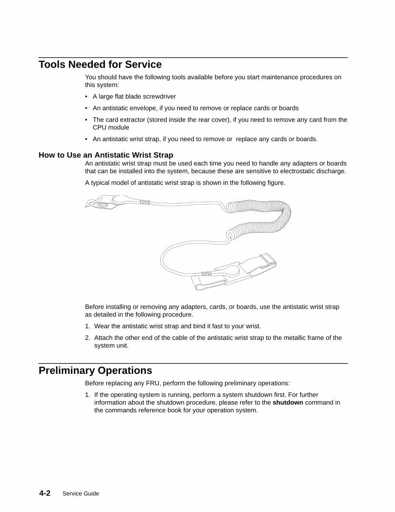
Service Guide4-2
Tools Needed for ServiceYou should have the following tools available before you start maintenance procedures onthis system:
• A large flat blade screwdriver
• An antistatic envelope, if you need to remove or replace cards or boards
• The card extractor (stored inside the rear cover), if you need to remove any card from theCPU module
• An antistatic wrist strap, if you need to remove or replace any cards or boards.
How to Use an Antistatic Wrist StrapAn antistatic wrist strap must be used each time you need to handle any adapters or boardsthat can be installed into the system, because these are sensitive to electrostatic discharge.
A typical model of antistatic wrist strap is shown in the following figure.
Before installing or removing any adapters, cards, or boards, use the antistatic wrist strapas detailed in the following procedure.
1. Wear the antistatic wrist strap and bind it fast to your wrist.
2. Attach the other end of the cable of the antistatic wrist strap to the metallic frame of thesystem unit.
Preliminary OperationsBefore replacing any FRU, perform the following preliminary operations:
1. If the operating system is running, perform a system shutdown first. For furtherinformation about the shutdown procedure, please refer to the shutdown command inthe commands reference book for your operation system.
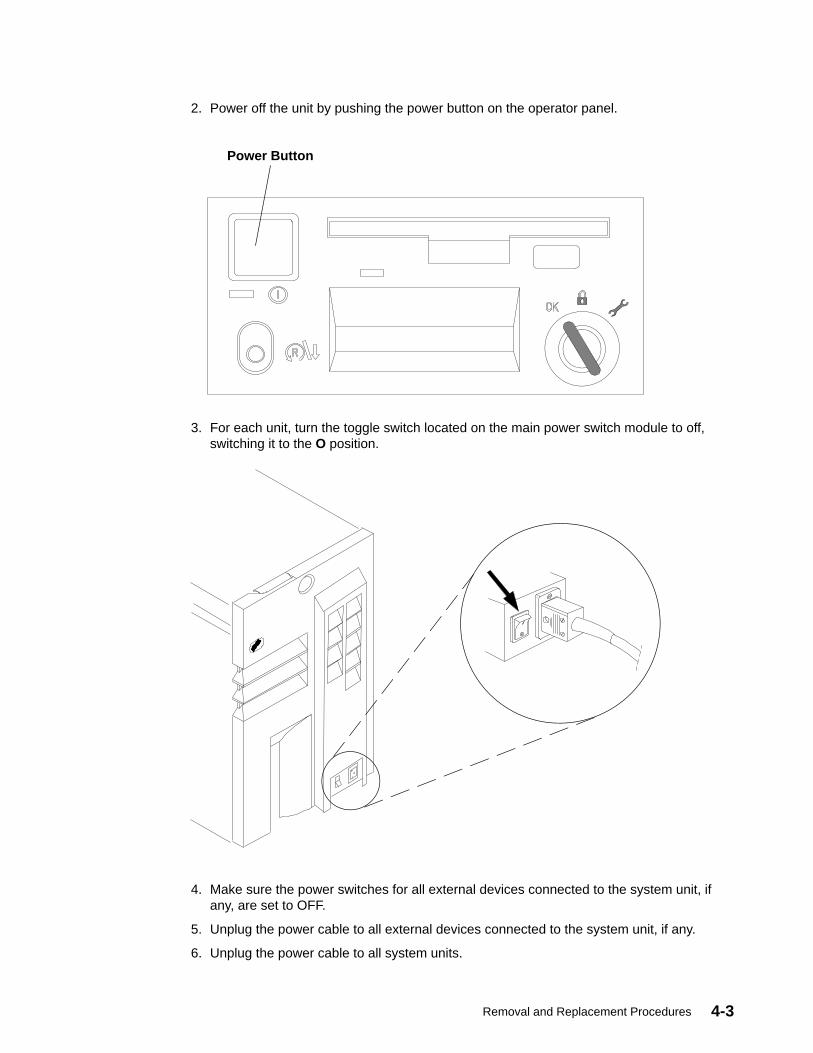
Removal and Replacement Procedures 4-3
2. Power off the unit by pushing the power button on the operator panel.
Power Button
3. For each unit, turn the toggle switch located on the main power switch module to off,switching it to the O position.
4. Make sure the power switches for all external devices connected to the system unit, ifany, are set to OFF.
5. Unplug the power cable to all external devices connected to the system unit, if any.
6. Unplug the power cable to all system units.

Service Guide4-4
Rear CoverAttention: Do not operate the system unit for a long time with the covers removed.Operating with the covers on ensures adequate cooling of the components. Remove thecovers only when required by the removal and replacement procedures illustrated in thisguide.
Removal1. Do the steps detailed in “Preliminary Operations” on page 4-2.
2. Turn the rear cover key clockwise to unlock the rear cover. The rear cover key is thesame as the one used on the operator panel.
3. With a firm grip on the cover, tilt it towards you and pull it upward as shown to remove itfrom the unit.
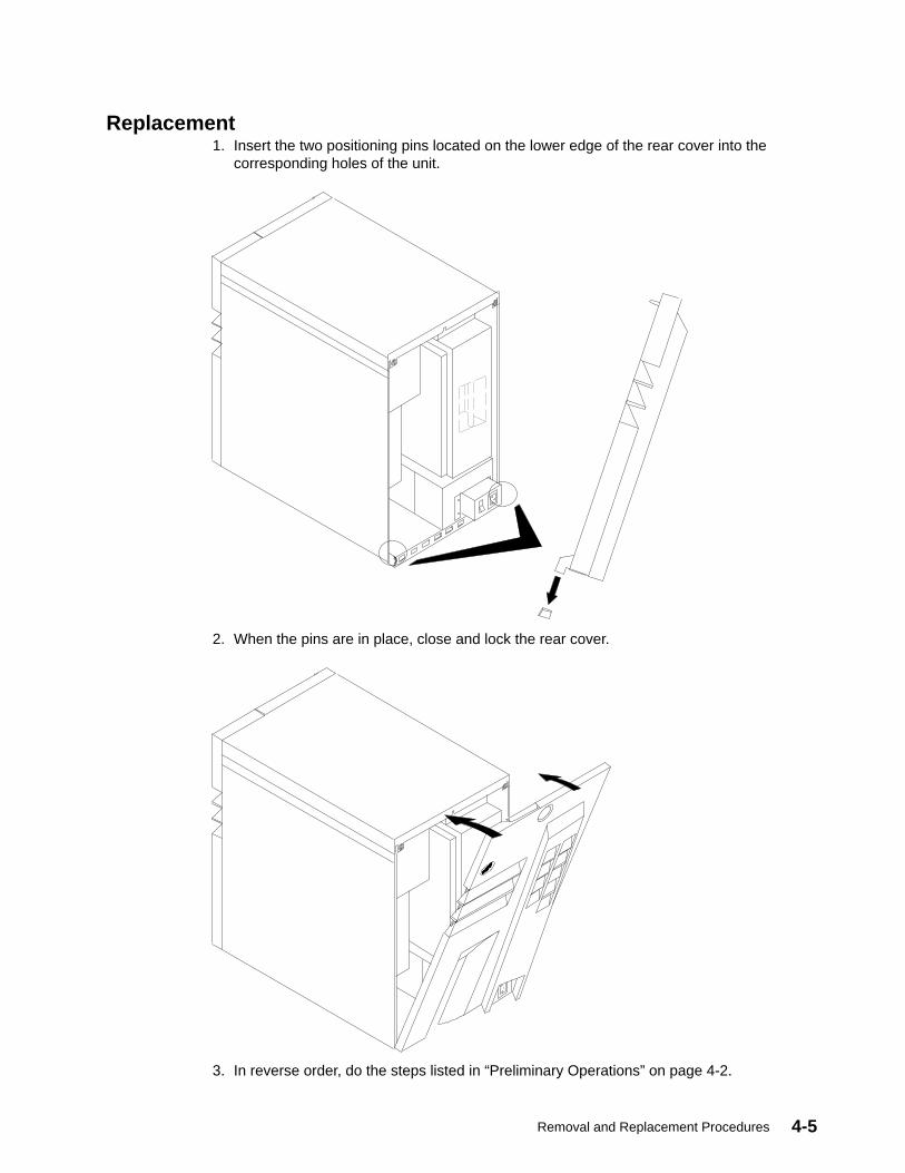
Removal and Replacement Procedures 4-5
Replacement1. Insert the two positioning pins located on the lower edge of the rear cover into the
corresponding holes of the unit.
2. When the pins are in place, close and lock the rear cover.
3. In reverse order, do the steps listed in “Preliminary Operations” on page 4-2.
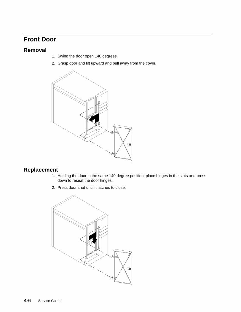
Service Guide4-6
Front Door
Removal1. Swing the door open 140 degrees.
2. Grasp door and lift upward and pull away from the cover.
Replacement1. Holding the door in the same 140 degree position, place hinges in the slots and press
down to reseat the door hinges.
2. Press door shut until it latches to close.
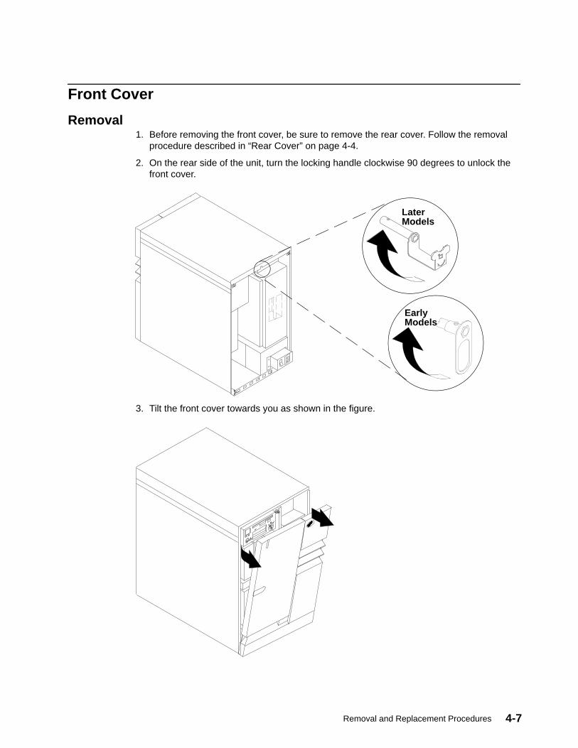
Removal and Replacement Procedures 4-7
Front Cover
Removal1. Before removing the front cover, be sure to remove the rear cover. Follow the removal
procedure described in “Rear Cover” on page 4-4.
2. On the rear side of the unit, turn the locking handle clockwise 90 degrees to unlock thefront cover.
LaterModels
EarlyModels
3. Tilt the front cover towards you as shown in the figure.
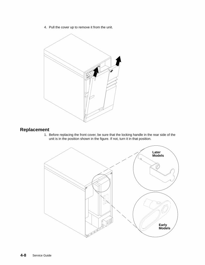
Service Guide4-8
4. Pull the cover up to remove it from the unit.
Replacement1. Before replacing the front cover, be sure that the locking handle in the rear side of the
unit is in the position shown in the figure. If not, turn it in that position.
LaterModels
EarlyModels
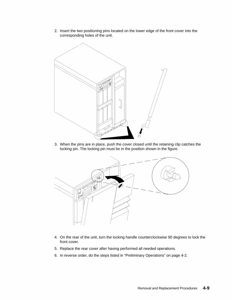
Removal and Replacement Procedures 4-9
2. Insert the two positioning pins located on the lower edge of the front cover into thecorresponding holes of the unit.
3. When the pins are in place, push the cover closed until the retaining clip catches thelocking pin. The locking pin must be in the position shown in the figure.
4. On the rear of the unit, turn the locking handle counterclockwise 90 degrees to lock thefront cover.
5. Replace the rear cover after having performed all needed operations.
6. In reverse order, do the steps listed in “Preliminary Operations” on page 4-2.
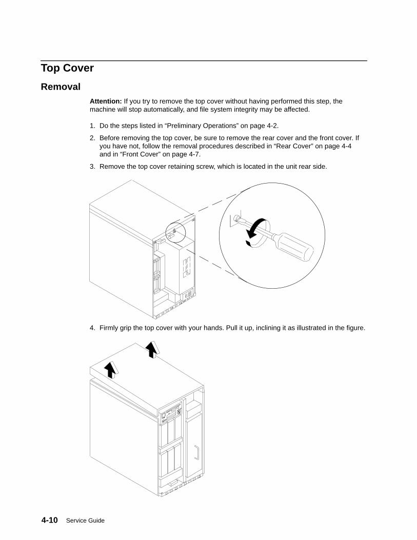
Service Guide4-10
Top Cover
RemovalAttention: If you try to remove the top cover without having performed this step, themachine will stop automatically, and file system integrity may be affected.
1. Do the steps listed in “Preliminary Operations” on page 4-2.
2. Before removing the top cover, be sure to remove the rear cover and the front cover. Ifyou have not, follow the removal procedures described in “Rear Cover” on page 4-4and in “Front Cover” on page 4-7.
3. Remove the top cover retaining screw, which is located in the unit rear side.
4. Firmly grip the top cover with your hands. Pull it up, inclining it as illustrated in the figure.
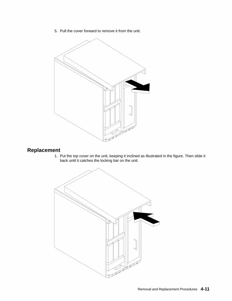
Removal and Replacement Procedures 4-11
5. Pull the cover forward to remove it from the unit.
Replacement1. Put the top cover on the unit, keeping it inclined as illustrated in the figure. Then slide it
back until it catches the locking bar on the unit.
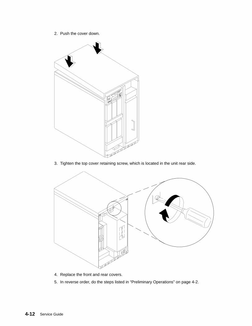
Service Guide4-12
2. Push the cover down.
3. Tighten the top cover retaining screw, which is located in the unit rear side.
4. Replace the front and rear covers.
5. In reverse order, do the steps listed in “Preliminary Operations” on page 4-2.

Removal and Replacement Procedures 4-13
Side Covers
RemovalThe following steps apply to each side cover:
1. Remove the rear cover, the front cover, and the top cover of the unit following theprocedures described respectively on pages 4-4, 4-7, and 4-10.
2. Unscrew the retaining screws indicated in the figure.
3. With a firm grip on the cover, tilt it towards you as shown.
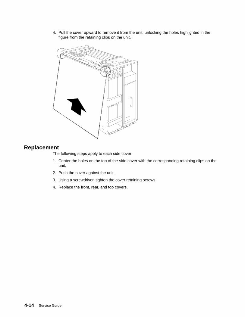
Service Guide4-14
4. Pull the cover upward to remove it from the unit, unlocking the holes highlighted in thefigure from the retaining clips on the unit.
ReplacementThe following steps apply to each side cover:
1. Center the holes on the top of the side cover with the corresponding retaining clips on theunit.
2. Push the cover against the unit.
3. Using a screwdriver, tighten the cover retaining screws.
4. Replace the front, rear, and top covers.

Removal and Replacement Procedures 4-15
Adapters
Removal1. Do the steps detailed in “Preliminary Operations” on page 4-2.
2. To access the MCA card cage, remove the rear, front, and top covers of the unitfollowing the procedures described respectively on pages 4-4, 4-7, and 4-10.
3. Record the location and type of the adapter. Disconnect any cables from the adapter. Ifyou are removing more than one adapter at a time, record which cable attaches to eachadapter.
4. Loosen the retaining screw shown in the figure.
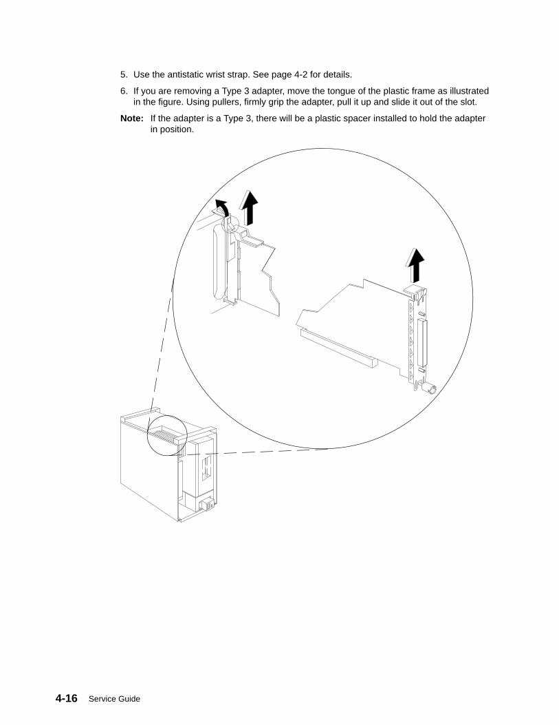
Service Guide4-16
5. Use the antistatic wrist strap. See page 4-2 for details.
6. If you are removing a Type 3 adapter, move the tongue of the plastic frame as illustratedin the figure. Using pullers, firmly grip the adapter, pull it up and slide it out of the slot.
Note: If the adapter is a Type 3, there will be a plastic spacer installed to hold the adapterin position.
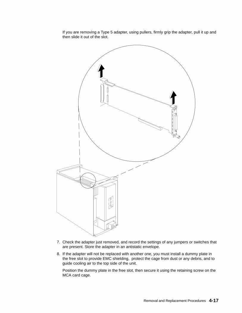
Removal and Replacement Procedures 4-17
If you are removing a Type 5 adapter, using pullers, firmly grip the adapter, pull it up andthen slide it out of the slot.
7. Check the adapter just removed, and record the settings of any jumpers or switches thatare present. Store the adapter in an antistatic envelope.
8. If the adapter will not be replaced with another one, you must install a dummy plate inthe free slot to provide EMC shielding, protect the cage from dust or any debris, and toguide cooling air to the top side of the unit.
Position the dummy plate in the free slot, then secure it using the retaining screw on theMCA card cage.

Service Guide4-18
ReplacementAttention: It is strongly recommended that you keep the adapter in the antistatic envelopeuntil you are ready to insert it in the required MCA card cage slot. This will protect it againstelectrostatic discharge. Be careful in handling the adapter: use the adapter pullers and donot touch the adapter components.
1. If you are replacing an existing adapter, set the jumpers or switches on the replacementadapter to match the settings you recorded from the adapter previously removed.Continue with step 3 of this procedure.
If you are installing the adapter for the first time, that means this adapter does notreplace another one. Set the jumpers or switches according to your configurationrequirements. Continue with next step.
2. Remove the dummy plate that covers the designated slot:
a. Loosen the retaining screw on the MCA card cage. Then slide the dummy plate out ofthe slot as indicated in the figure. Store this dummy plate for possible future use.
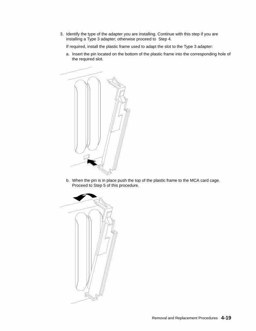
Removal and Replacement Procedures 4-19
3. Identify the type of the adapter you are installing. Continue with this step if you areinstalling a Type 3 adapter; otherwise proceed to Step 4.
If required, install the plastic frame used to adapt the slot to the Type 3 adapter:
a. Insert the pin located on the bottom of the plastic frame into the corresponding hole ofthe required slot.
b. When the pin is in place push the top of the plastic frame to the MCA card cage.Proceed to Step 5 of this procedure.
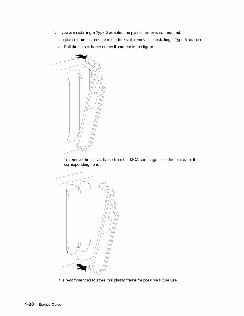
Service Guide4-20
4. If you are installing a Type 5 adapter, the plastic frame is not required.
If a plastic frame is present in the free slot, remove it if installing a Type 5 adapter.
a. Pull the plastic frame out as illustrated in the figure.
b. To remove the plastic frame from the MCA card cage, slide the pin out of thecorresponding hole.
It is recommended to store this plastic frame for possible future use.
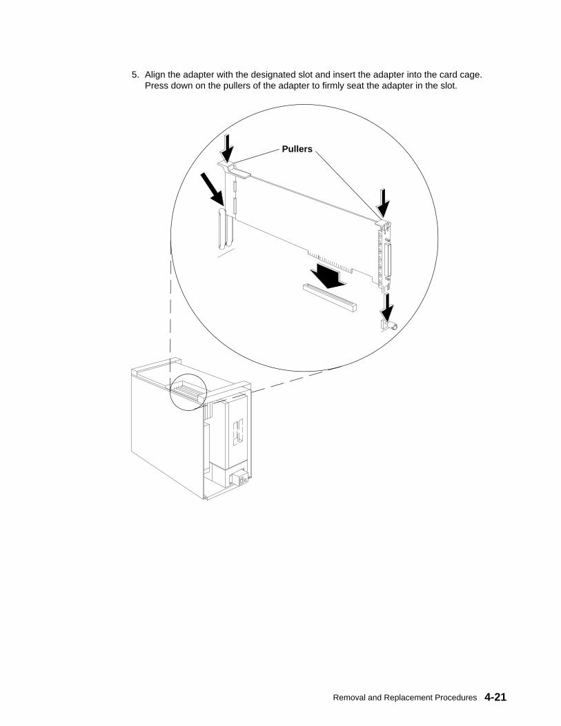
Removal and Replacement Procedures 4-21
5. Align the adapter with the designated slot and insert the adapter into the card cage.Press down on the pullers of the adapter to firmly seat the adapter in the slot.
Pullers

Service Guide4-22
6. Tighten the retaining screw on the MCA card cage to secure the adapter in the slot.
7. Connect any connector cables to the adapter just installed.
8. Replace the top, front, and rear covers.
9. In reverse, do order the steps listed in “Preliminary Operations” on page 4-2.

Removal and Replacement Procedures 4-23
Expansion Unit Operator Panel and Power-on Light
Removal1. Do the steps detailed in “Preliminary Operations” on page 4-2.
2. To access the expansion unit operator panel and power-on light, remove the rear, front.and top covers of the unit following the procedures described, respectively, on pages4-4, 4-7, and 4-10.
3. Loosen the screws that secure the operator panel to the top of the expansion unitchassis.
4. Pull the operator panel out until you can access the rear of the panel, and loosen thescrews that secure the bezel to the operator panel.
5. Disconnect both ends of the power-on light cable and remove from the operator panel.
Replacement1. Connect both ends of the power-on light cable to the appropriate connectors in the
operator panel.
2. Tighten the screws holding the bezel to the operator panel.
3. Hold the operator panel in position and tighten the screws that secure the operator panelto the top of the expansion unit chassis.
4. Replace the top, front, and rear covers.
5. In reverse order, do the steps listed in “Preliminary Operations” on page 4-2.
ToP07
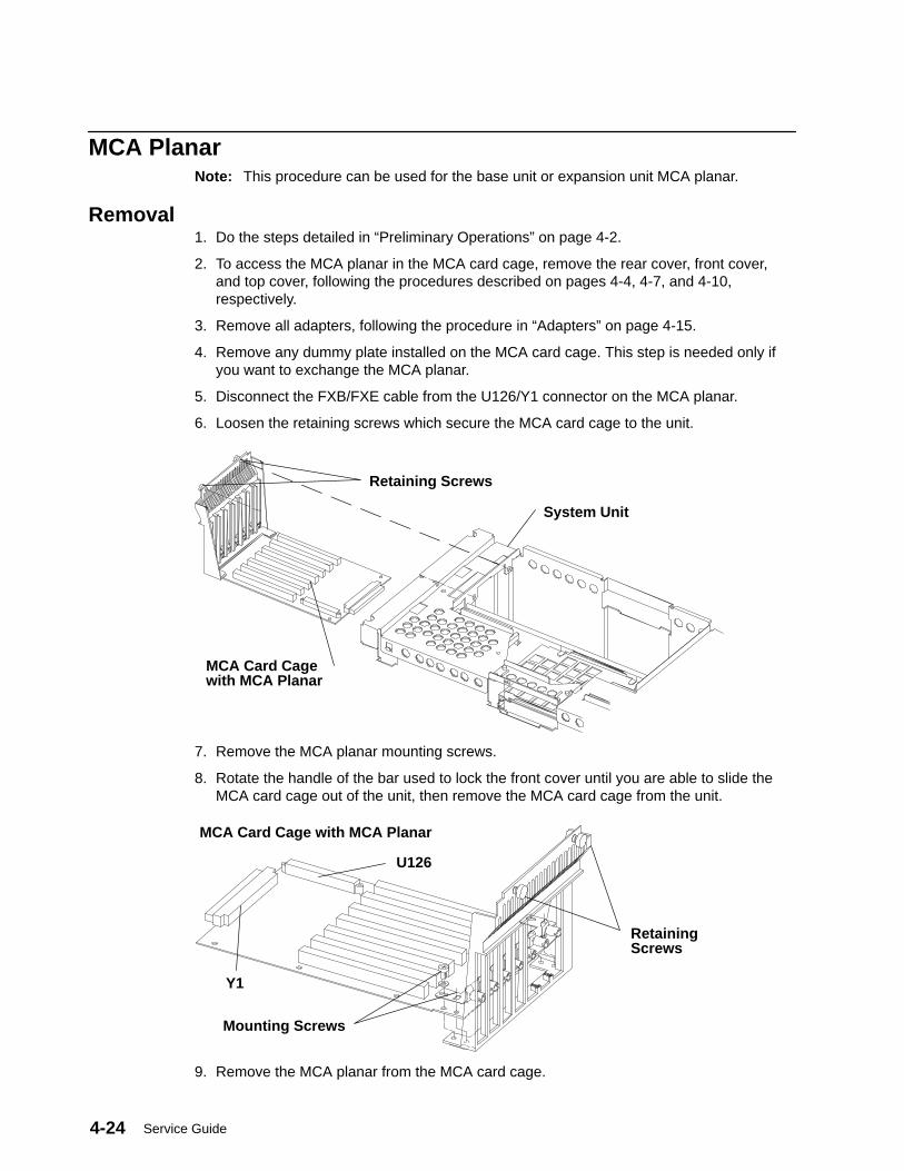
Service Guide4-24
MCA PlanarNote: This procedure can be used for the base unit or expansion unit MCA planar.
Removal1. Do the steps detailed in “Preliminary Operations” on page 4-2.
2. To access the MCA planar in the MCA card cage, remove the rear cover, front cover,and top cover, following the procedures described on pages 4-4, 4-7, and 4-10,respectively.
3. Remove all adapters, following the procedure in “Adapters” on page 4-15.
4. Remove any dummy plate installed on the MCA card cage. This step is needed only ifyou want to exchange the MCA planar.
5. Disconnect the FXB/FXE cable from the U126/Y1 connector on the MCA planar.
6. Loosen the retaining screws which secure the MCA card cage to the unit.
Retaining Screws
MCA Card Cagewith MCA Planar
System Unit
7. Remove the MCA planar mounting screws.
8. Rotate the handle of the bar used to lock the front cover until you are able to slide theMCA card cage out of the unit, then remove the MCA card cage from the unit.
Mounting Screws
RetainingScrews
MCA Card Cage with MCA Planar
Y1
U126
9. Remove the MCA planar from the MCA card cage.

Removal and Replacement Procedures 4-25
Replacement1. Position the MCA planar into the MCA card cage.
2. Secure the MCA planar to the MCA card cage tightening the mounting screws.
3. Replace the MCA card cage into the unit, then rotate the handle of the bar used to lockthe front cover.
4. Replace the retaining screws which secure the MCA card cage to the unit.
5. Reconnect the FXB/FXE cable to the U126/Y1 connector on the MCA planar.
6. Replace any dummy plate that was removed from the MCA card cage.
7. Replace all adapters removed from the MCA card cage, following the procedure in“Adapters” on page 4-15.
8. Replace the top, front, and rear covers after having performed all needed operations.
9. In reverse order do the steps listed in “Preliminary Operations” on page 4-2.
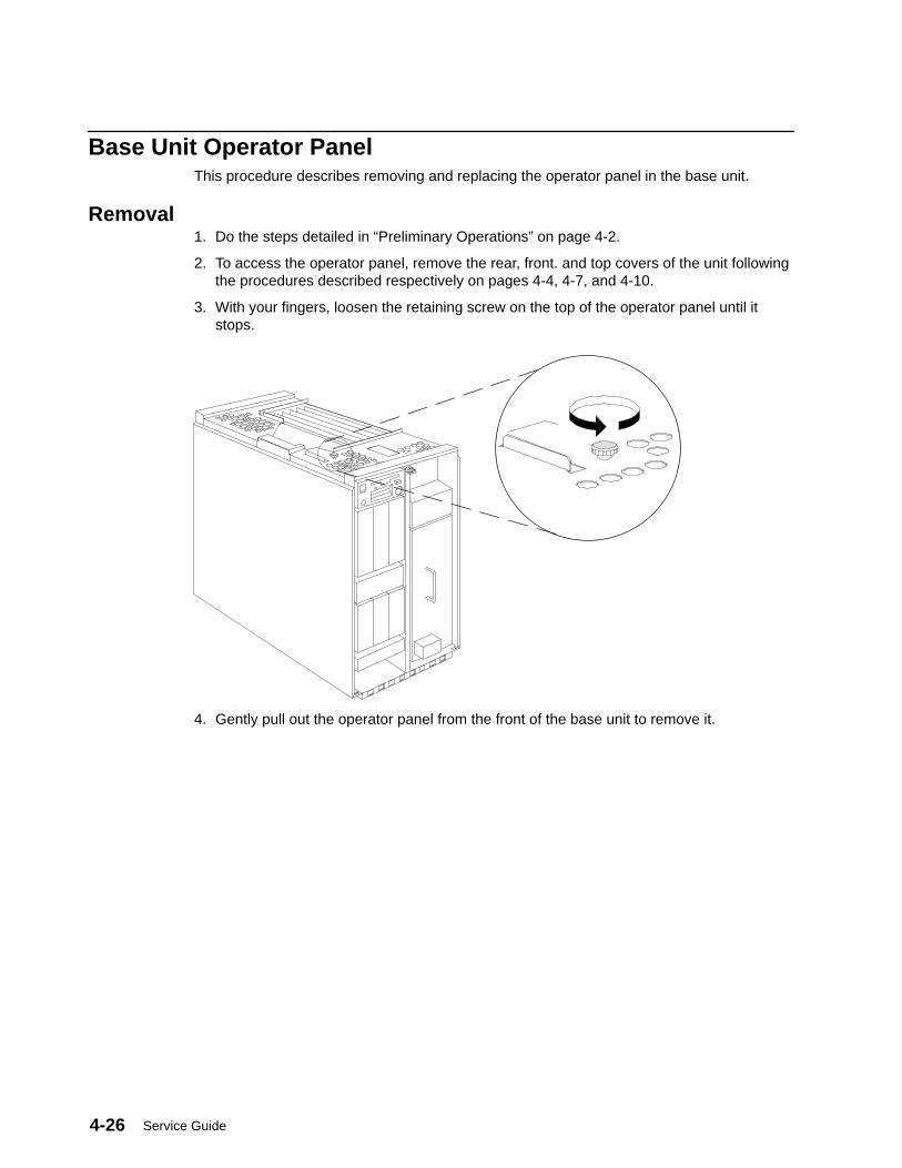
Service Guide4-26
Base Unit Operator PanelThis procedure describes removing and replacing the operator panel in the base unit.
Removal1. Do the steps detailed in “Preliminary Operations” on page 4-2.
2. To access the operator panel, remove the rear, front. and top covers of the unit followingthe procedures described respectively on pages 4-4, 4-7, and 4-10.
3. With your fingers, loosen the retaining screw on the top of the operator panel until itstops.
4. Gently pull out the operator panel from the front of the base unit to remove it.
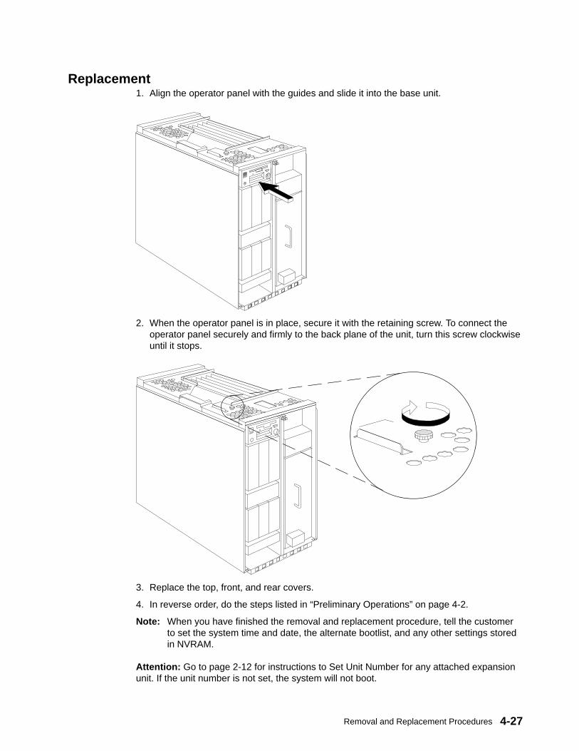
Removal and Replacement Procedures 4-27
Replacement1. Align the operator panel with the guides and slide it into the base unit.
2. When the operator panel is in place, secure it with the retaining screw. To connect theoperator panel securely and firmly to the back plane of the unit, turn this screw clockwiseuntil it stops.
3. Replace the top, front, and rear covers.
4. In reverse order, do the steps listed in “Preliminary Operations” on page 4-2.
Note: When you have finished the removal and replacement procedure, tell the customerto set the system time and date, the alternate bootlist, and any other settings storedin NVRAM.
Attention: Go to page 2-12 for instructions to Set Unit Number for any attached expansionunit. If the unit number is not set, the system will not boot.
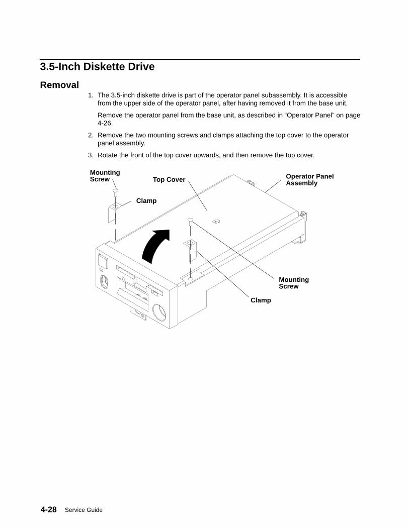
Service Guide4-28
3.5-Inch Diskette Drive
Removal1. The 3.5-inch diskette drive is part of the operator panel subassembly. It is accessible
from the upper side of the operator panel, after having removed it from the base unit.
Remove the operator panel from the base unit, as described in “Operator Panel” on page4-26.
2. Remove the two mounting screws and clamps attaching the top cover to the operatorpanel assembly.
3. Rotate the front of the top cover upwards, and then remove the top cover.
Operator PanelAssembly
MountingScrew Top Cover
MountingScrew
Clamp
Clamp

Removal and Replacement Procedures 4-29
4. Disconnect the 3.5-inch diskette drive connector.
5. For later models, remove the two mounting screws attaching the diskette drive to theoperator panel assembly, then remove the diskette drive from the operator panelassembly.
6. From the bottom of the diskette drive, remove the four mounting screws attaching thediskette drive to the diskette drive support.
Diskette Drive
Diskette DriveSupport
Diskette DriveConnector
Diskette Drive SupportMounting Screws
Later Models
7. For earlier models, remove the two mounting screws attaching the bezel to the bottom ofthe operator panel assembly, and then remove the bezel.
8. For earlier models, remove the two mounting screws attaching the diskette drive to thebottom of the operator panel assembly.
9. Remove the diskette drive from the operator panel assembly.
Diskette Drive Connector
Mounting ScrewAttachingDiskette Drive
Mounting ScrewAttaching Bezel
Mounting Screw AttachingDiskette Drive
Mounting ScrewAttaching Bezel
Power Connector
Data Connector
Power Connector
Earlier Models
ReplacementReplace in the reverse order of the removal procedure.
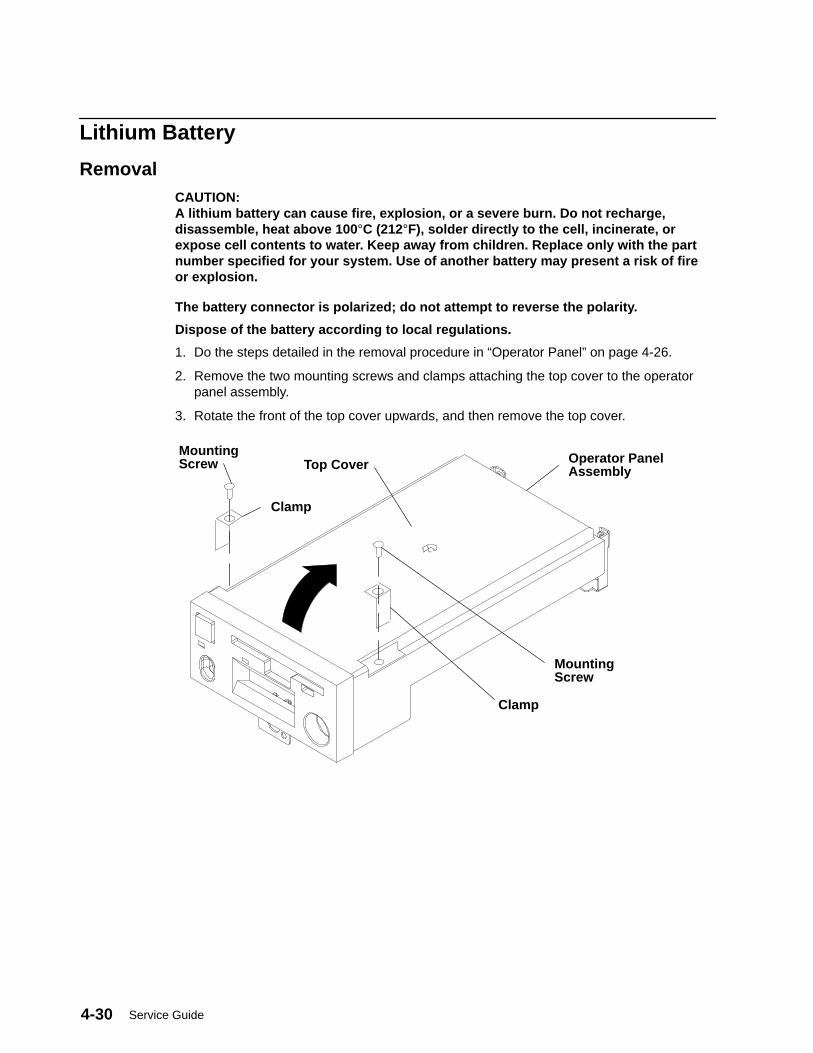
Service Guide4-30
Lithium Battery
RemovalCAUTION:A lithium battery can cause fire, explosion, or a severe burn. Do not recharge,disassemble, heat above 100 °C (212°F), solder directly to the cell, incinerate, orexpose cell contents to water. Keep away from children. Replace only with the partnumber specified for your system. Use of another battery may present a risk of fireor explosion.
The battery connector is polarized; do not attempt to reverse the polarity.
Dispose of the battery according to local regulations.
1. Do the steps detailed in the removal procedure in “Operator Panel” on page 4-26.
2. Remove the two mounting screws and clamps attaching the top cover to the operatorpanel assembly.
3. Rotate the front of the top cover upwards, and then remove the top cover.
Operator PanelAssembly
MountingScrew Top Cover
MountingScrew
Clamp
Clamp
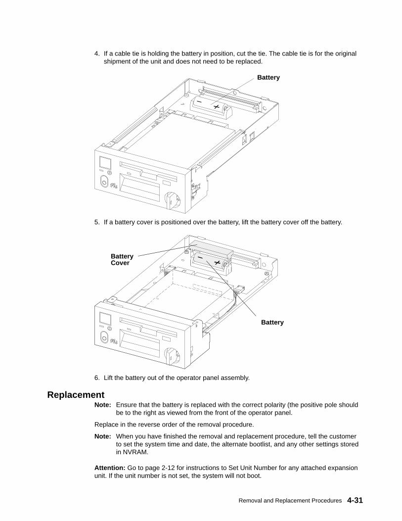
Removal and Replacement Procedures 4-31
4. If a cable tie is holding the battery in position, cut the tie. The cable tie is for the originalshipment of the unit and does not need to be replaced.
Battery
5. If a battery cover is positioned over the battery, lift the battery cover off the battery.
Battery
BatteryCover
6. Lift the battery out of the operator panel assembly.
ReplacementNote: Ensure that the battery is replaced with the correct polarity (the positive pole should
be to the right as viewed from the front of the operator panel.
Replace in the reverse order of the removal procedure.
Note: When you have finished the removal and replacement procedure, tell the customerto set the system time and date, the alternate bootlist, and any other settings storedin NVRAM.
Attention: Go to page 2-12 for instructions to Set Unit Number for any attached expansionunit. If the unit number is not set, the system will not boot.
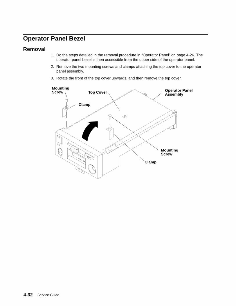
Service Guide4-32
Operator Panel Bezel
Removal1. Do the steps detailed in the removal procedure in “Operator Panel” on page 4-26. The
operator panel bezel is then accessible from the upper side of the operator panel.
2. Remove the two mounting screws and clamps attaching the top cover to the operatorpanel assembly.
3. Rotate the front of the top cover upwards, and then remove the top cover.
Operator PanelAssembly
MountingScrew Top Cover
MountingScrew
Clamp
Clamp
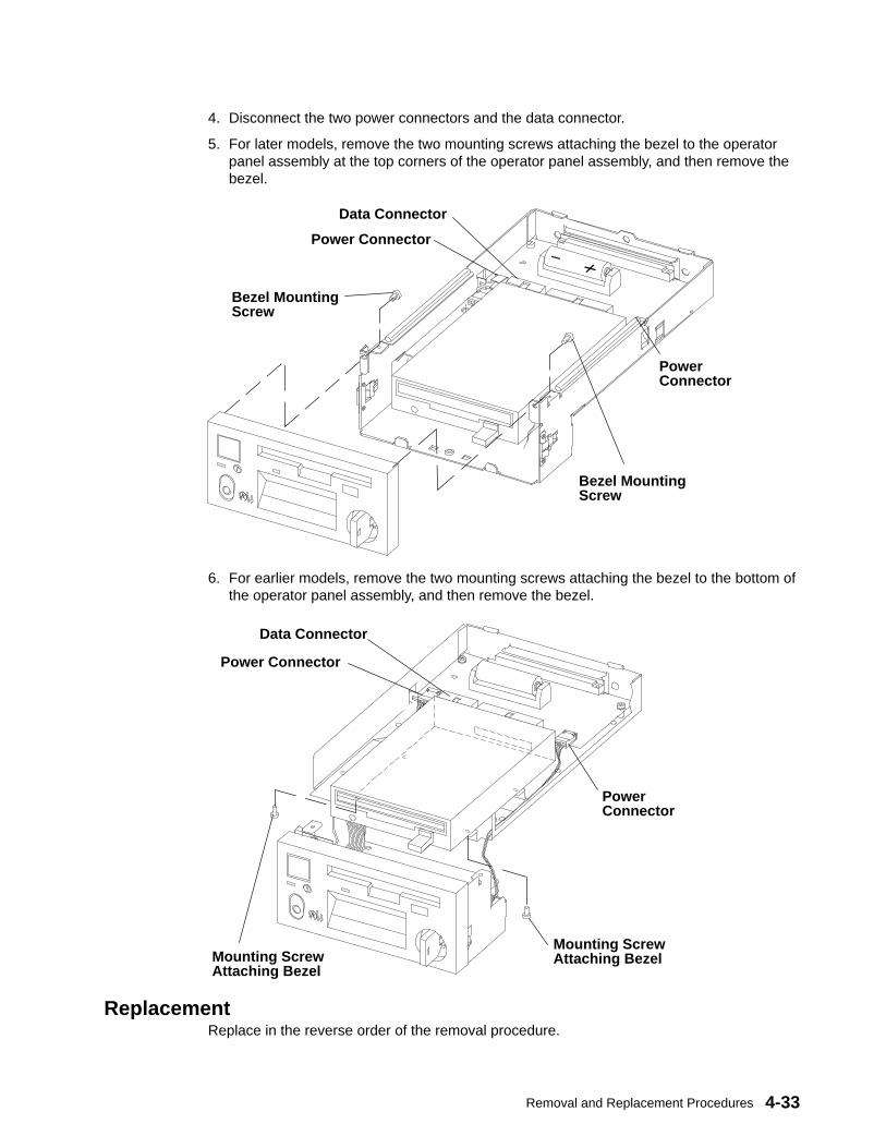
Removal and Replacement Procedures 4-33
4. Disconnect the two power connectors and the data connector.
5. For later models, remove the two mounting screws attaching the bezel to the operatorpanel assembly at the top corners of the operator panel assembly, and then remove thebezel.
Bezel MountingScrew
Bezel MountingScrew
Power Connector
Data Connector
PowerConnector
6. For earlier models, remove the two mounting screws attaching the bezel to the bottom ofthe operator panel assembly, and then remove the bezel.
Mounting ScrewAttaching Bezel
Mounting ScrewAttaching Bezel
Power Connector
Data Connector
PowerConnector
ReplacementReplace in the reverse order of the removal procedure.
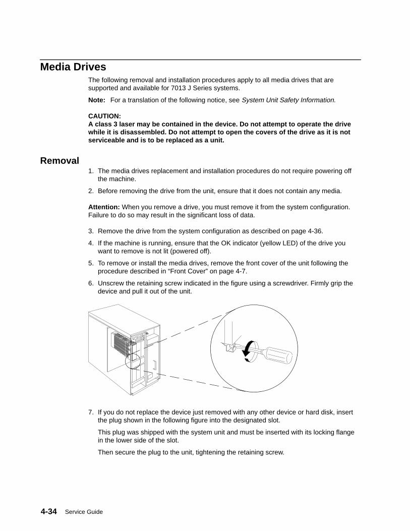
Service Guide4-34
Media DrivesThe following removal and installation procedures apply to all media drives that aresupported and available for 7013 J Series systems.
Note: For a translation of the following notice, see System Unit Safety Information.
CAUTION:A class 3 laser may be contained in the device. Do not attempt to operate the drivewhile it is disassembled. Do not attempt to open the covers of the drive as it is notserviceable and is to be replaced as a unit.
Removal1. The media drives replacement and installation procedures do not require powering off
the machine.
2. Before removing the drive from the unit, ensure that it does not contain any media.
Attention: When you remove a drive, you must remove it from the system configuration.Failure to do so may result in the significant loss of data.
3. Remove the drive from the system configuration as described on page 4-36.
4. If the machine is running, ensure that the OK indicator (yellow LED) of the drive youwant to remove is not lit (powered off).
5. To remove or install the media drives, remove the front cover of the unit following theprocedure described in “Front Cover” on page 4-7.
6. Unscrew the retaining screw indicated in the figure using a screwdriver. Firmly grip thedevice and pull it out of the unit.
7. If you do not replace the device just removed with any other device or hard disk, insertthe plug shown in the following figure into the designated slot.
This plug was shipped with the system unit and must be inserted with its locking flangein the lower side of the slot.
Then secure the plug to the unit, tightening the retaining screw.
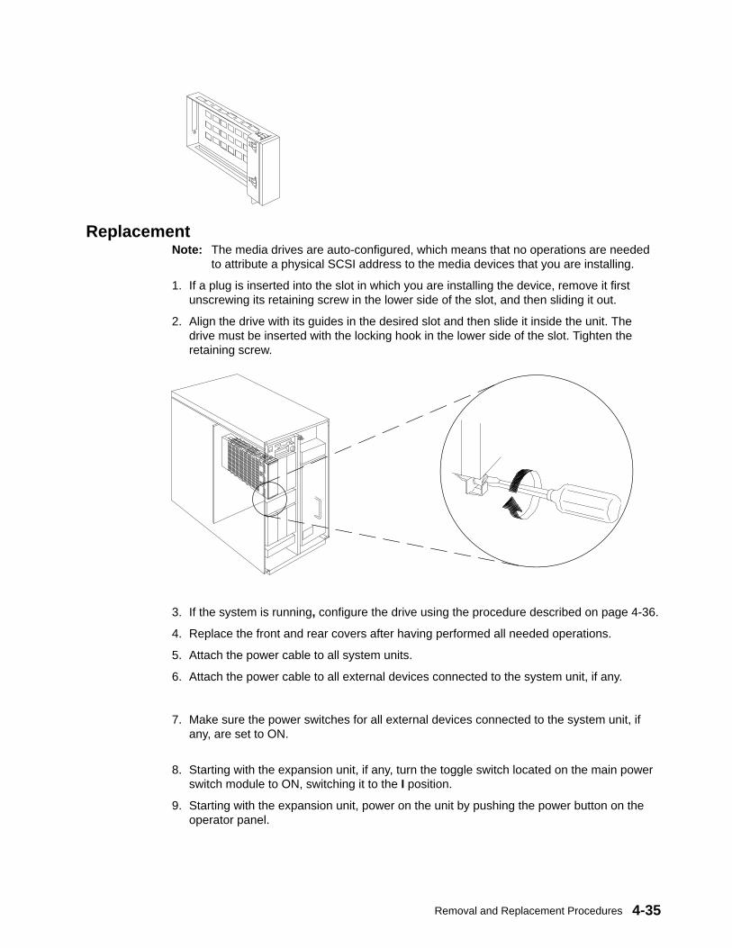
Removal and Replacement Procedures 4-35
ReplacementNote: The media drives are auto-configured, which means that no operations are needed
to attribute a physical SCSI address to the media devices that you are installing.
1. If a plug is inserted into the slot in which you are installing the device, remove it firstunscrewing its retaining screw in the lower side of the slot, and then sliding it out.
2. Align the drive with its guides in the desired slot and then slide it inside the unit. Thedrive must be inserted with the locking hook in the lower side of the slot. Tighten theretaining screw.
3. If the system is running, configure the drive using the procedure described on page 4-36.
4. Replace the front and rear covers after having performed all needed operations.
5. Attach the power cable to all system units.
6. Attach the power cable to all external devices connected to the system unit, if any.
7. Make sure the power switches for all external devices connected to the system unit, ifany, are set to ON.
8. Starting with the expansion unit, if any, turn the toggle switch located on the main powerswitch module to ON, switching it to the I position.
9. Starting with the expansion unit, power on the unit by pushing the power button on theoperator panel.
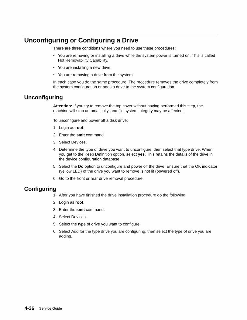
Service Guide4-36
Unconfiguring or Configuring a DriveThere are three conditions where you need to use these procedures:
• You are removing or installing a drive while the system power is turned on. This is calledHot Removability Capability.
• You are installing a new drive.
• You are removing a drive from the system.
In each case you do the same procedure. The procedure removes the drive completely fromthe system configuration or adds a drive to the system configuration.
UnconfiguringAttention: If you try to remove the top cover without having performed this step, themachine will stop automatically, and file system integrity may be affected.
To unconfigure and power off a disk drive:
1. Login as root .
2. Enter the smit command.
3. Select Devices.
4. Determine the type of drive you want to unconfigure; then select that type drive. Whenyou get to the Keep Definition option, select yes . This retains the details of the drive inthe device configuration database.
5. Select the Do option to unconfigure and power off the drive. Ensure that the OK indicator(yellow LED) of the drive you want to remove is not lit (powered off).
6. Go to the front or rear drive removal procedure.
Configuring1. After you have finished the drive installation procedure do the following:
2. Login as root .
3. Enter the smit command.
4. Select Devices.
5. Select the type of drive you want to configure.
6. Select Add for the type drive you are configuring, then select the type of drive you areadding.
Removal and Replacement Procedures 4-37
Media Drives (Carrier, Drive)Notes:
1. The following procedures apply to any type of media drive supported by thesystem. For each media drive, refer to Adapters, Devices, and Cable Information,order number SA23-2764, for details regarding the jumper settings for the specificdrive in your carrier.
2. If your drive is different from the drawing, carefully note the positions of the cableand jumpers during the removal steps for reference during the replacement steps.
Carrier and Drive
Removal1. Remove the media drive from the unit, as described in “Media Drives” on page 4-34.
2. Cut the warranty label.
3. Loosen the carrier mounting screws used to hold the device in the carrier.
4. Remove the carrier cover.
5. Disconnect any cable connected to any connector on the device.
6. Lift the device out of the carrier.
Replacement1. Position the device on the bottom support of the carrier.
2. Connect any cable to the dedicated connector on the device.
3. Install the carrier cover. Then secure the device and the carrier tightening theappropriate carrier mounting screws with a torque of 1 Newton/Meter ± 0.1Newton/Meter.
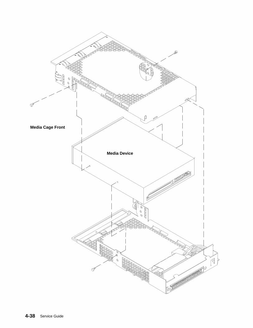
Service Guide4-38
Media Cage Front
Media Device
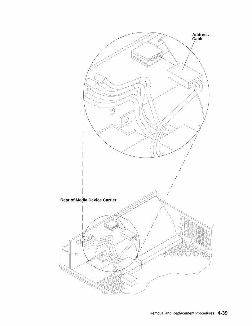
Removal and Replacement Procedures 4-39
Rear of Media Device Carrier
AddressCable

Service Guide4-40
Disk DrivesNotes:
1. Use caution when handling all disk drives. Drives are more likely to be damagedduring installation and service. Bumping or handling drives roughly causes latentfailures. Do not stack drives and always use appropriate ESD practices. A drop ofas little as 1/4-inch can cause latent failures. Because drives can take 30 secondsto spin down, allow at least a 30 second delay after switching a drive off beforeremoving it from the system unit.
2. It is not necessary to power down the system to remove or install the disk drives.
3. The procedures for removal and replacement of the disk drives described in thefollowing pages are applicable to each disk drive removed from or installed ineither the base unit or the expansion unit, both in the front and in the rear side.The two figures related respectively to the removal of the disk drive from the unit,and to the replacement of the disk drive in the unit, show the base unit front side,but these must be considered in any case.
Attention: The 9.1GB Disk Drive can only be installed in positions on the front of the unit.Positions B2 and B3 in model J50 base unit cannot be used for new disk drives. If thesystem is upgraded to a model J50, drives moved during the model upgrade can be used inthese positions.
Removal1. If the system is running, unconfigure the disk drive you are removing by following the
“Unconfigure” procedure on page 4-36.
2. If the system is running and you are removing:
a. a disk drive subject to the high removability feature (lower front), go to step 3.
b. a disk drive from the rear of the unit, go to step 7.
c. a disk drive from the upper front of the unit, go to step 11.

Removal and Replacement Procedures 4-41
Lower Front Disk DrivesNote: If High Security is installed (installed on all systems at the factory), the front cover
must be removed before a disk drive can be removed. See “Front Cover” on page4-7.
3. Open the front door of the unit.
4. Be sure the yellow indicator on the drive you are removing is off (powered off); firmly gripthe handle of the disk drive you are removing and pull the disk drive out of the unit.
5. If you are not replacing the disk drive that you just removed, close the door that wasopened in step 3 of this procedure.
6. If you are replacing the disk drive, go to page 4-42
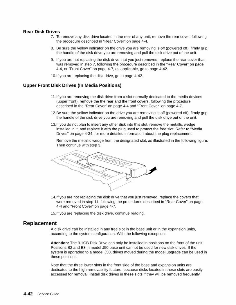
Service Guide4-42
Rear Disk Drives7. To remove any disk drive located in the rear of any unit, remove the rear cover, following
the procedure described in “Rear Cover” on page 4-4.
8. Be sure the yellow indicator on the drive you are removing is off (powered off); firmly gripthe handle of the disk drive you are removing and pull the disk drive out of the unit.
9. If you are not replacing the disk drive that you just removed, replace the rear cover thatwas removed in step 7, following the procedure described in the “Rear Cover” on page4-4, or “Front Cover” on page 4-7, as applicable, go to page 4-42.
10.If you are replacing the disk drive, go to page 4-42.
Upper Front Disk Drives (In Media Positions)
11. If you are removing the disk drive from a slot normally dedicated to the media devices(upper front), remove the the rear and the front covers, following the proceduredescribed in the “Rear Cover” on page 4-4 and “Front Cover” on page 4-7.
12.Be sure the yellow indicator on the drive you are removing is off (powered off); firmly gripthe handle of the disk drive you are removing and pull the disk drive out of the unit.
13.If you do not plan to insert any other disk into this slot, remove the metallic wedgeinstalled in it, and replace it with the plug used to protect the free slot. Refer to “MediaDrives” on page 4-34, for more detailed information about the plug replacement.
Remove the metallic wedge from the designated slot, as illustrated in the following figure.Then continue with step 3.
14.If you are not replacing the disk drive that you just removed, replace the covers thatwere removed in step 11, following the procedures described in “Rear Cover” on page4-4 and “Front Cover” on page 4-7.
15.If you are replacing the disk drive, continue reading.
ReplacementA disk drive can be installed in any free slot in the base unit or in the expansion units,according to the system configuration. With the following exception:
Attention: The 9.1GB Disk Drive can only be installed in positions on the front of the unit.Positions B2 and B3 in model J50 base unit cannot be used for new disk drives. If thesystem is upgraded to a model J50, drives moved during the model upgrade can be used inthese positions.
Note that the three lower slots in the front side of the base and expansion units arededicated to the high removability feature, because disks located in these slots are easilyaccessed for removal. Install disk drives in these slots if they will be removed frequently.
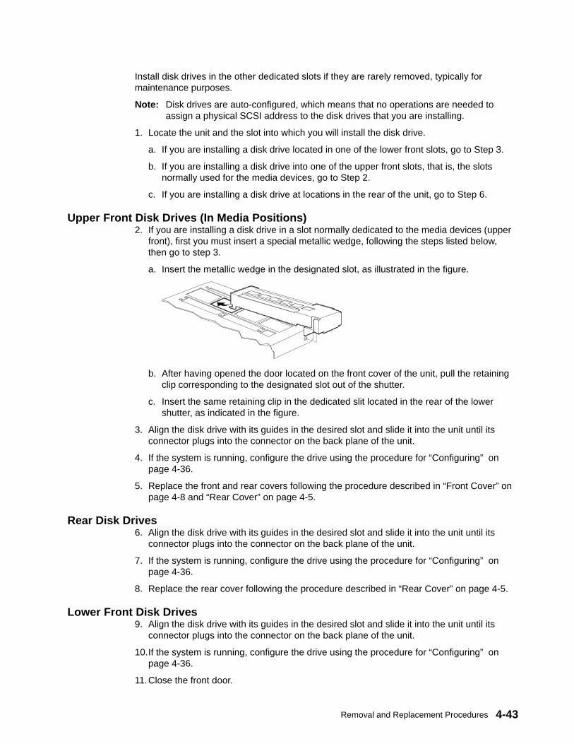
Removal and Replacement Procedures 4-43
Install disk drives in the other dedicated slots if they are rarely removed, typically formaintenance purposes.
Note: Disk drives are auto-configured, which means that no operations are needed toassign a physical SCSI address to the disk drives that you are installing.
1. Locate the unit and the slot into which you will install the disk drive.
a. If you are installing a disk drive located in one of the lower front slots, go to Step 3.
b. If you are installing a disk drive into one of the upper front slots, that is, the slotsnormally used for the media devices, go to Step 2.
c. If you are installing a disk drive at locations in the rear of the unit, go to Step 6.
Upper Front Disk Drives (In Media Positions)2. If you are installing a disk drive in a slot normally dedicated to the media devices (upper
front), first you must insert a special metallic wedge, following the steps listed below,then go to step 3.
a. Insert the metallic wedge in the designated slot, as illustrated in the figure.
b. After having opened the door located on the front cover of the unit, pull the retainingclip corresponding to the designated slot out of the shutter.
c. Insert the same retaining clip in the dedicated slit located in the rear of the lowershutter, as indicated in the figure.
3. Align the disk drive with its guides in the desired slot and slide it into the unit until itsconnector plugs into the connector on the back plane of the unit.
4. If the system is running, configure the drive using the procedure for “Configuring” onpage 4-36.
5. Replace the front and rear covers following the procedure described in “Front Cover” onpage 4-8 and “Rear Cover” on page 4-5.
Rear Disk Drives6. Align the disk drive with its guides in the desired slot and slide it into the unit until its
connector plugs into the connector on the back plane of the unit.
7. If the system is running, configure the drive using the procedure for “Configuring” onpage 4-36.
8. Replace the rear cover following the procedure described in “Rear Cover” on page 4-5.
Lower Front Disk Drives9. Align the disk drive with its guides in the desired slot and slide it into the unit until its
connector plugs into the connector on the back plane of the unit.
10.If the system is running, configure the drive using the procedure for “Configuring” onpage 4-36.
11.Close the front door.
Service Guide4-44
Disk Drives, (Carrier, 8 bit Disk Drive)Note: The following procedures apply to 8 bit disk drives supported by the system. If the
drive is not a 1GB type 0662 or a 2GB type 0664, carefully note the positions of thecable and jumpers during the removal steps for reference during the replacementsteps.
Carrier and Disk Drive
Removal1. Remove the disk drive from the unit, as described in the removal procedure in “Disk
Drives” on page 4-40.
2. Cut the warranty label.
3. Loosen the mounting screws used to secure the carrier cover, using a screwdriver.
4. Remove the carrier cover.
5. Disconnect all cables connected to the disk drive, both on the front and on the rear.
6. Loosen the mounting screws holding the carrier guide.
7. Pull the guide out of the carrier.
8. Loosen the mounting screws holding the disk drive in the carrier, using a screwdriver.
9. Lift the disk drive out of the carrier.
Installation1. Connect all cables to the corresponding connectors at the front of the disk drive, as
shown on page 4-45.
2. Position the disk drive on the bottom support of the carrier. Tighten the screws to securethe disk drive to the carrier.
3. Place the carrier guide in position, then secure it with the mounting screws.
4. Connect the 68 pin flex cable to the drive first, with the blue edge to the center of thecarrier. Connect other end to converter card.
5. Connect both ends of the DC power cable.
6. Install the carrier cover. Tighten the appropriate mounting screws to secure the disk driveto the carrier cover.
7. Replace the carrier unit to the system, as described in the replacement procedure in“Disk Drives” on page 4-40.

Removal and Replacement Procedures 4-45
540MB, 1.0GB, 2.0GB SCSI-2 SE 8 bit Disk Drives
SCSI IDCable
LED Cable
LED Cable to DiskDrive
SeeDetailA
Front ofCarrier
See Detail B on page 4-47 for bracket removal

Service Guide4-46
Power Cable
SCSI CableGreen LED Cable
Note Orientation ofSCSI CableConnector
Detail A

Removal and Replacement Procedures 4-47
Bracket RemovalIf you are replacing a disk drive that is attached to the carrier with a bracket, you need tomove the bracket from the old drive to the new drive.
Bracket
Top Of Drive
Bottom Of Drive
Detail B
Service Guide4-48
Disk Drives (Carrier, 16 bit Disk Drive)Note: The following procedures apply to 16 bit disk drives supported by the system. If the
drive is not a 1.1GB, 2.2GB, 4.5GB, 2.0GB, or 9.1GB disk drive, carefully note thepositions of the cable and jumpers during the removal steps for reference during thereplacement steps.
Attention: The 9.1GB Disk Drive can only be installed in positions on the front of the unit.
Carrier and Disk Drive
Removal1. Remove the disk drive from the unit, as described in the removal procedure in “Disk
Drives” on page 4-40.
2. Cut the warranty label.
3. Loosen the mounting screws used to secure the carrier cover, using a screwdriver.
4. Remove the carrier cover.
5. Disconnect all cables connected to the disk drive, both on the front and on the rear.
6. Loosen the mounting screws holding the guide on the carrier.
7. Pull the guide out of the carrier.
8. Loosen the mounting screws holding the disk drive in the carrier, using a screwdriver.
9. Lift the disk drive out of the carrier.
Installation1. Connect all cables to the corresponding connectors at the front of the disk drive, as
shown on page 4-49 and 4-50.
2. Position the disk drive on the bottom support of the carrier. Tighten the screws to securethe disk drive to the carrier.
3. Place the guide of the carrier in position, then secure it with the mounting screws.
4. Connect the 68 pin flex cable to the drive first, with the blue edge to the center of thecarrier. Connect other end to converter card.
5. Connect both ends of the DC power cable.
6. Install the carrier cover. Then secure the disk drive and the carrier tightening theappropriate mounting screws.
7. Replace the carrier unit to the system, as described in the replacement procedure in“Disk Drives” on page 4-40.
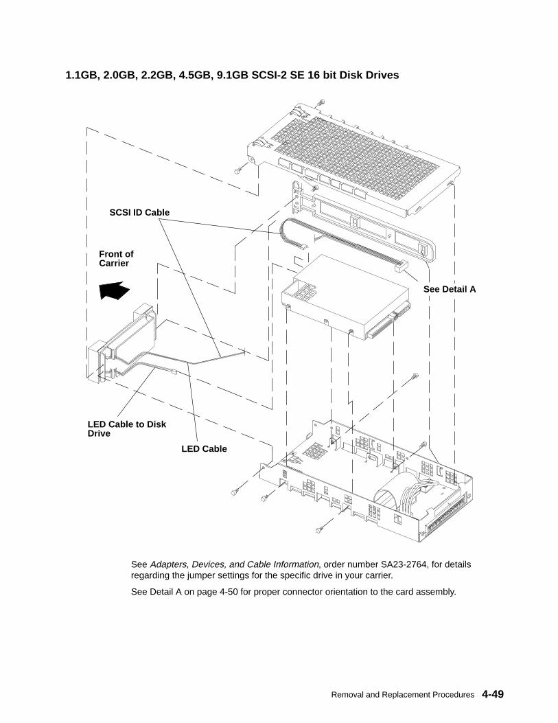
Removal and Replacement Procedures 4-49
1.1GB, 2.0GB, 2.2GB, 4.5GB, 9.1GB SCSI-2 SE 16 bit Disk Drives
SCSI ID Cable
LED Cable
LED Cable to DiskDrive
Front ofCarrier
See Detail A
See Adapters, Devices, and Cable Information, order number SA23-2764, for detailsregarding the jumper settings for the specific drive in your carrier.
See Detail A on page 4-50 for proper connector orientation to the card assembly.
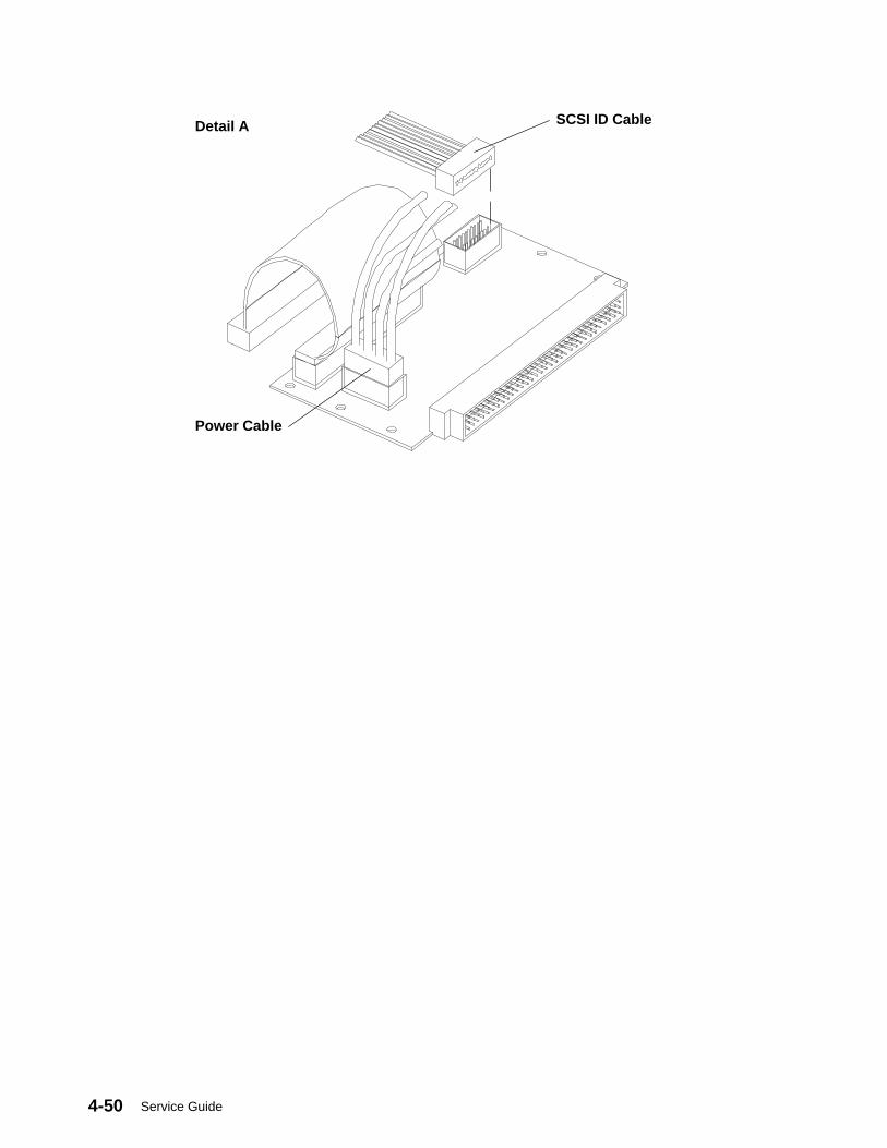
Service Guide4-50
SCSI ID Cable
Power Cable
Detail A
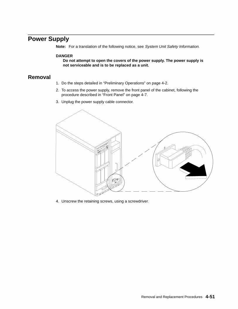
Removal and Replacement Procedures 4-51
Power SupplyNote: For a translation of the following notice, see System Unit Safety Information.
DANGERDo not attempt to open the covers of the power supply. The power supply isnot serviceable and is to be replaced as a unit.
Removal1. Do the steps detailed in “Preliminary Operations” on page 4-2.
2. To access the power supply, remove the front panel of the cabinet, following theprocedure described in “Front Panel” on page 4-7.
3. Unplug the power supply cable connector.
4. Unscrew the retaining screws, using a screwdriver.
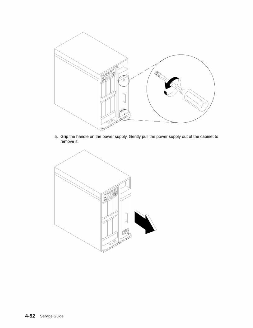
Service Guide4-52
5. Grip the handle on the power supply. Gently pull the power supply out of the cabinet toremove it.
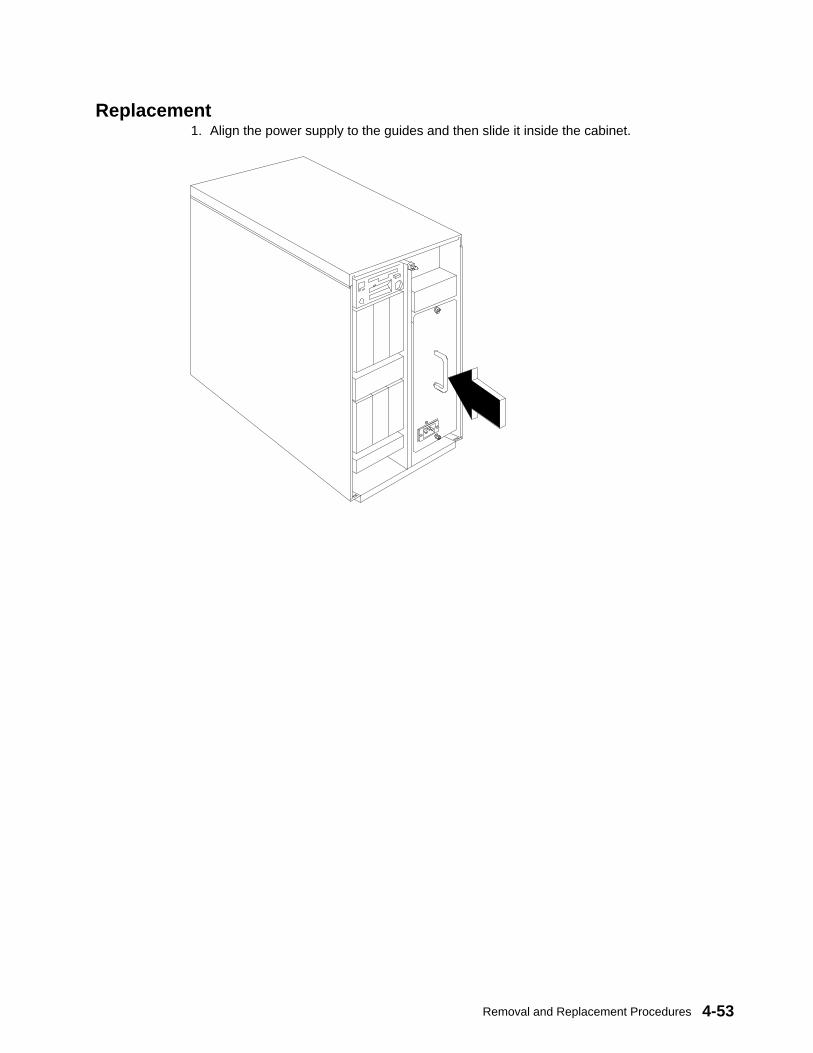
Removal and Replacement Procedures 4-53
Replacement1. Align the power supply to the guides and then slide it inside the cabinet.
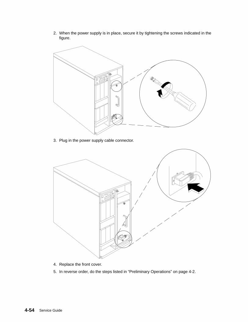
Service Guide4-54
2. When the power supply is in place, secure it by tightening the screws indicated in thefigure.
3. Plug in the power supply cable connector.
4. Replace the front cover.
5. In reverse order, do the steps listed in “Preliminary Operations” on page 4-2.
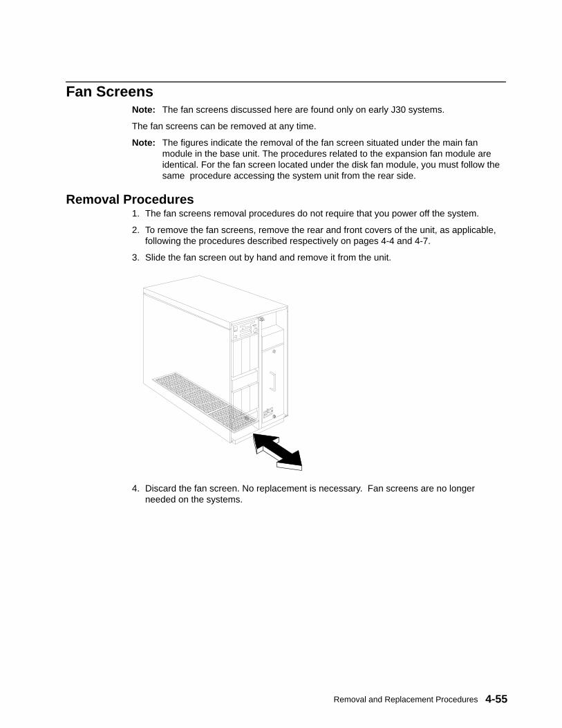
Removal and Replacement Procedures 4-55
Fan ScreensNote: The fan screens discussed here are found only on early J30 systems.
The fan screens can be removed at any time.
Note: The figures indicate the removal of the fan screen situated under the main fanmodule in the base unit. The procedures related to the expansion fan module areidentical. For the fan screen located under the disk fan module, you must follow thesame procedure accessing the system unit from the rear side.
Removal Procedures1. The fan screens removal procedures do not require that you power off the system.
2. To remove the fan screens, remove the rear and front covers of the unit, as applicable,following the procedures described respectively on pages 4-4 and 4-7.
3. Slide the fan screen out by hand and remove it from the unit.
4. Discard the fan screen. No replacement is necessary. Fan screens are no longerneeded on the systems.
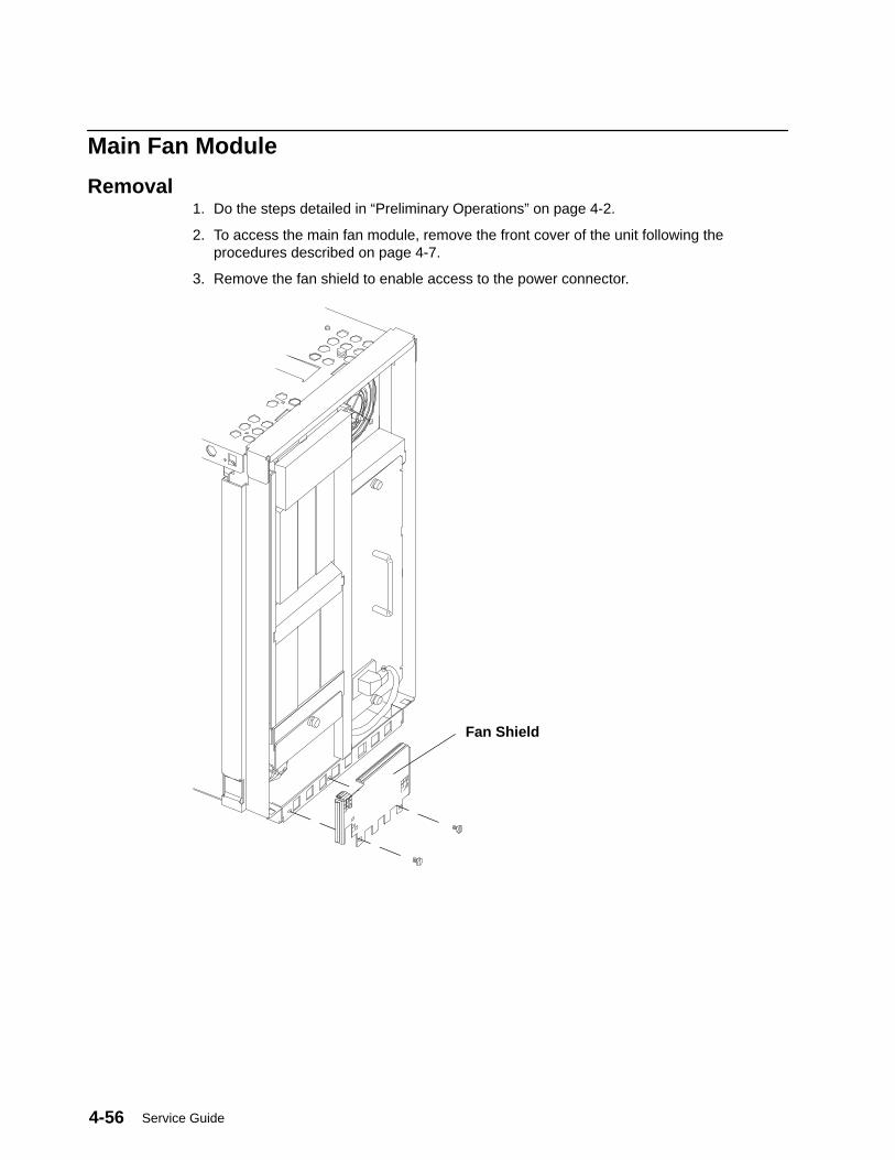
Service Guide4-56
Main Fan Module
Removal1. Do the steps detailed in “Preliminary Operations” on page 4-2.
2. To access the main fan module, remove the front cover of the unit following theprocedures described on page 4-7.
3. Remove the fan shield to enable access to the power connector.
Fan Shield

Removal and Replacement Procedures 4-57
Attention: If, for any reason, the machine was still running, it stops automatically when youdisconnect the fan power connector, and file system integrity may be affected.
4. Disconnect the fan power connector, by pressing and pulling the connector to unplug it.
5. Loosen the retaining screw, then pull the fan module out of the unit.
6. To exchange an individual fan, see “Individual Fan” on page 4-64.
ReplacementDo in reverse order the steps listed in “Removal”.
Note: If the fan power connector is not properly connected, and you try to start the system,it will not run.
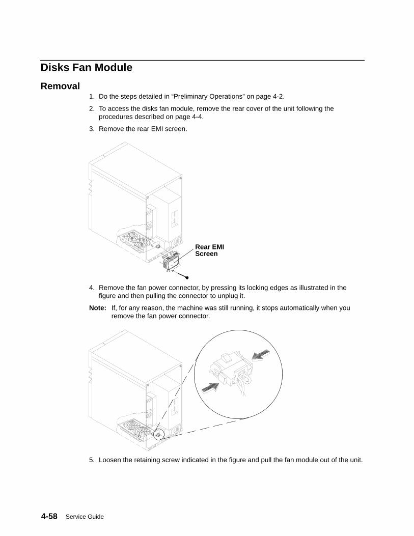
Service Guide4-58
Disks Fan Module
Removal1. Do the steps detailed in “Preliminary Operations” on page 4-2.
2. To access the disks fan module, remove the rear cover of the unit following theprocedures described on page 4-4.
3. Remove the rear EMI screen.
Rear EMIScreen
4. Remove the fan power connector, by pressing its locking edges as illustrated in thefigure and then pulling the connector to unplug it.
Note: If, for any reason, the machine was still running, it stops automatically when youremove the fan power connector.
5. Loosen the retaining screw indicated in the figure and pull the fan module out of the unit.

Removal and Replacement Procedures 4-59
ReplacementDo in reverse order the steps listed in “Removal”.
Note: If you do not connect the fan power connector properly, and then you try to start themachine, it will not run.
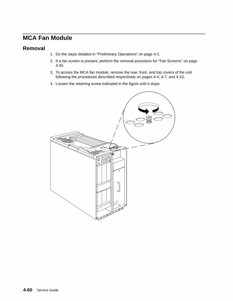
Service Guide4-60
MCA Fan Module
Removal1. Do the steps detailed in “Preliminary Operations” on page 4-2.
2. If a fan screen is present, perform the removal procedure for “Fan Screens” on page4-55.
3. To access the MCA fan module, remove the rear, front, and top covers of the unitfollowing the procedures described respectively on pages 4-4, 4-7, and 4-10.
4. Loosen the retaining screw indicated in the figure until it stops.
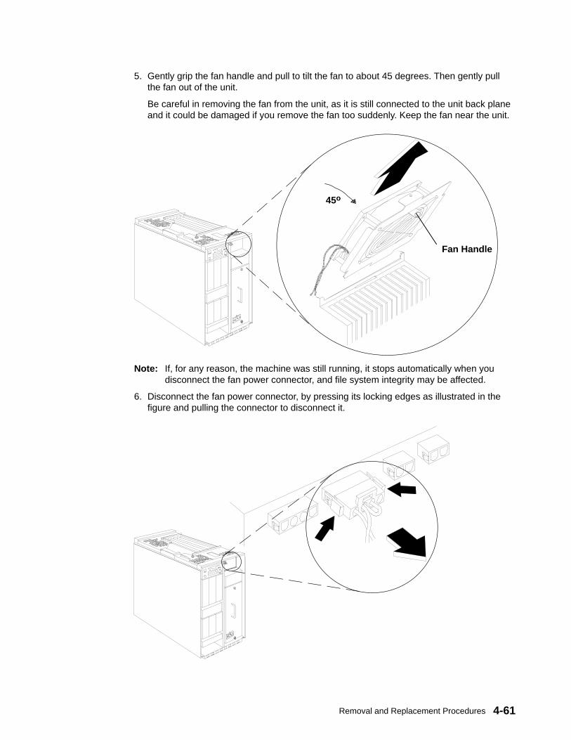
Removal and Replacement Procedures 4-61
5. Gently grip the fan handle and pull to tilt the fan to about 45 degrees. Then gently pullthe fan out of the unit.
Be careful in removing the fan from the unit, as it is still connected to the unit back planeand it could be damaged if you remove the fan too suddenly. Keep the fan near the unit.
Fan Handle
45o
Note: If, for any reason, the machine was still running, it stops automatically when youdisconnect the fan power connector, and file system integrity may be affected.
6. Disconnect the fan power connector, by pressing its locking edges as illustrated in thefigure and pulling the connector to disconnect it.
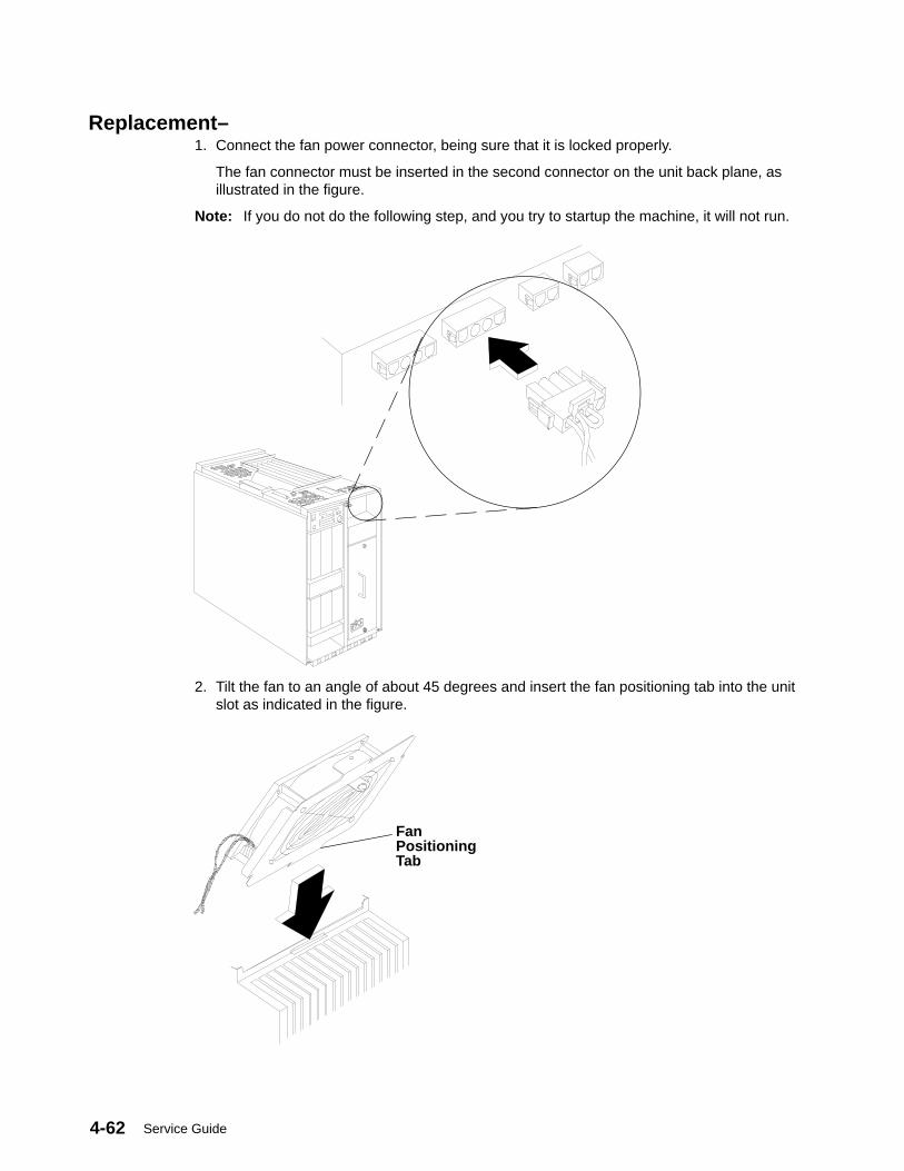
Service Guide4-62
Replacement–1. Connect the fan power connector, being sure that it is locked properly.
The fan connector must be inserted in the second connector on the unit back plane, asillustrated in the figure.
Note: If you do not do the following step, and you try to startup the machine, it will not run.
2. Tilt the fan to an angle of about 45 degrees and insert the fan positioning tab into the unitslot as indicated in the figure.
FanPositioningTab
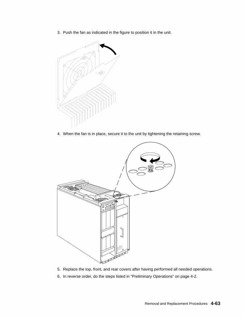
Removal and Replacement Procedures 4-63
3. Push the fan as indicated in the figure to position it in the unit.
4. When the fan is in place, secure it to the unit by tightening the retaining screw.
5. Replace the top, front, and rear covers after having performed all needed operations.
6. In reverse order, do the steps listed in “Preliminary Operations” on page 4-2.

Service Guide4-64
Individual FansNote: The procedures detailed below apply to all fans mounted on the following fan
modules:
• Base unit main fan module• Expansion unit main fan module• Disks fan module.
Removal1. Do the steps detailed in “Preliminary Operations” on page 4-2.
2. Remove the defective fan module from the unit, as described either in “Main FanModule” on page 4-56 or in “Disks Fan Module” on page 4-58, as applicable.
3. Identify the defective fan, performing the following steps.
a. After you have completely removed the designated fan module from the unit, plug thefan module power connector into the corresponding connector in the unit.
b. Power on the system
c. Check the fan module to determine fan which is not running.
d. Shut down and power down the system again.
e. Unplug the fan module power connector.
4. Cut the four rubber fasteners used to lock the defective fan to the module.
5. Disconnect the power cable for the defective fan.
6. Loosen the retaining screws from the defective fan.
7. Remove the defective fan from the module.
Replacement1. Insert four new rubber fasteners into the corresponding holes on the fan module.
2. Position the new fan, and insert the four rubber fasteners installed in the previous stepinto the corresponding holes on the new fan.
3. Connect the power cable for the new fan.
4. Secure the new fan to the fan module by tightening its retaining screws.
5. Replace the fan module in the unit, as described either in “Main Fan Module” on page4-56 or in “Disks Fan Module” on page 4-58, as applicable.
6. In reverse order, do the steps listed in “Preliminary Operations” on page 4-2.
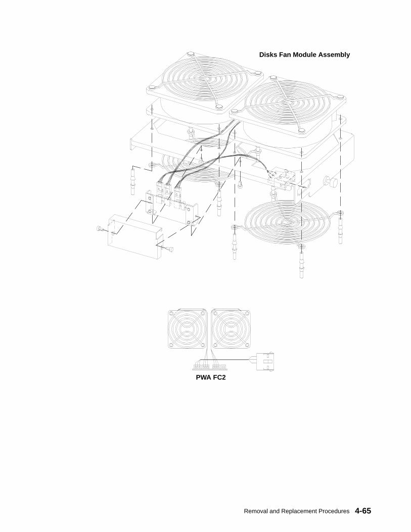
Removal and Replacement Procedures 4-65
Disks Fan Module Assembly
PWA FC2

Service Guide4-66
Base Unit Fan Module Assembly
PWA FC5
High Speed FansAir Flow
Medium Speed Fans
Expansion Unit Fan Module Assembly
PWA FC5
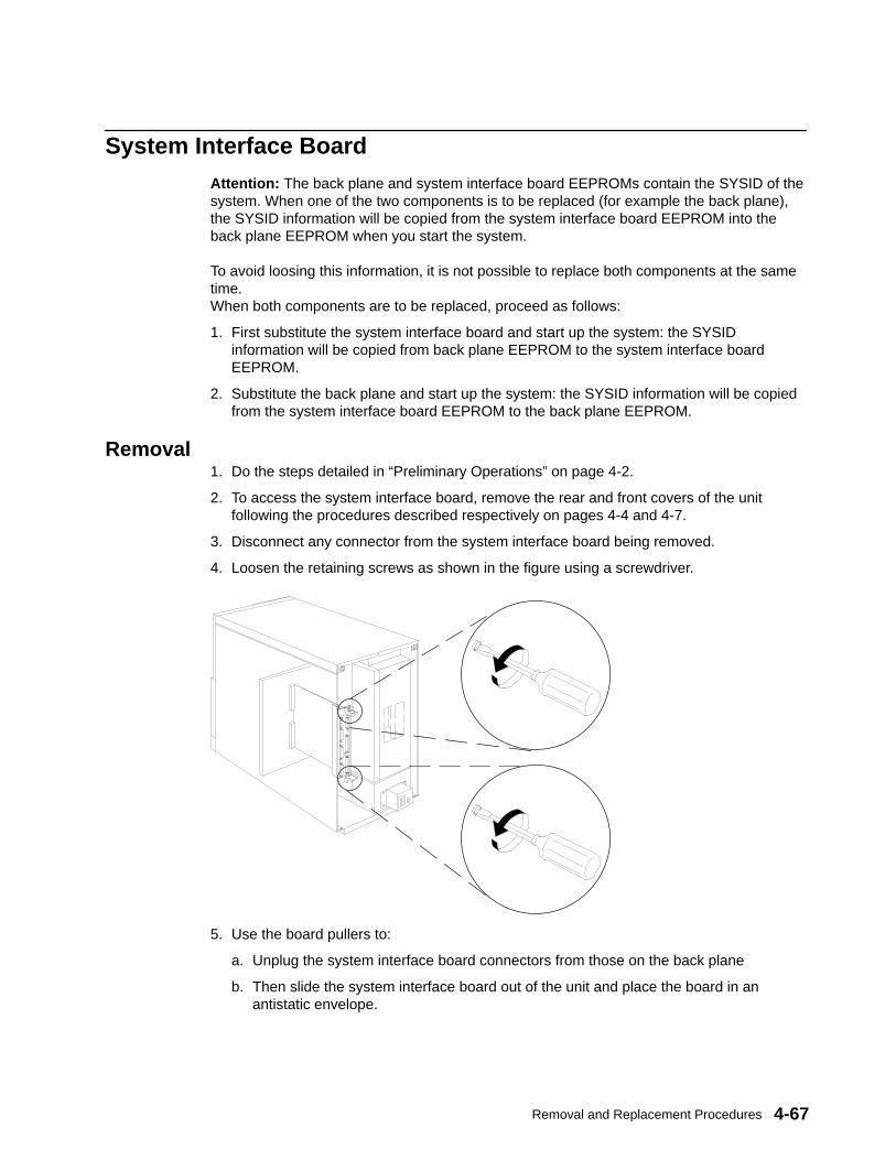
Removal and Replacement Procedures 4-67
System Interface BoardAttention: The back plane and system interface board EEPROMs contain the SYSID of thesystem. When one of the two components is to be replaced (for example the back plane),the SYSID information will be copied from the system interface board EEPROM into theback plane EEPROM when you start the system.
To avoid loosing this information, it is not possible to replace both components at the sametime.When both components are to be replaced, proceed as follows:
1. First substitute the system interface board and start up the system: the SYSIDinformation will be copied from back plane EEPROM to the system interface boardEEPROM.
2. Substitute the back plane and start up the system: the SYSID information will be copiedfrom the system interface board EEPROM to the back plane EEPROM.
Removal1. Do the steps detailed in “Preliminary Operations” on page 4-2.
2. To access the system interface board, remove the rear and front covers of the unitfollowing the procedures described respectively on pages 4-4 and 4-7.
3. Disconnect any connector from the system interface board being removed.
4. Loosen the retaining screws as shown in the figure using a screwdriver.
5. Use the board pullers to:
a. Unplug the system interface board connectors from those on the back plane
b. Then slide the system interface board out of the unit and place the board in anantistatic envelope.
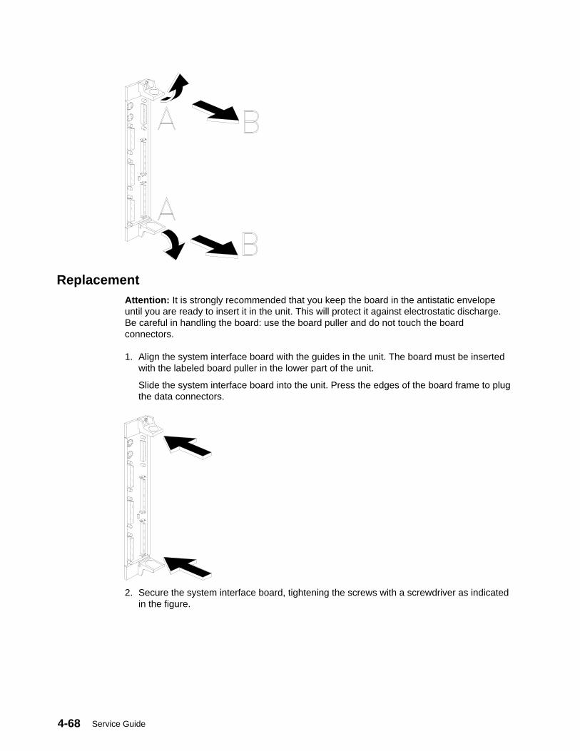
Service Guide4-68
ReplacementAttention: It is strongly recommended that you keep the board in the antistatic envelopeuntil you are ready to insert it in the unit. This will protect it against electrostatic discharge.Be careful in handling the board: use the board puller and do not touch the boardconnectors.
1. Align the system interface board with the guides in the unit. The board must be insertedwith the labeled board puller in the lower part of the unit.
Slide the system interface board into the unit. Press the edges of the board frame to plugthe data connectors.
2. Secure the system interface board, tightening the screws with a screwdriver as indicatedin the figure.
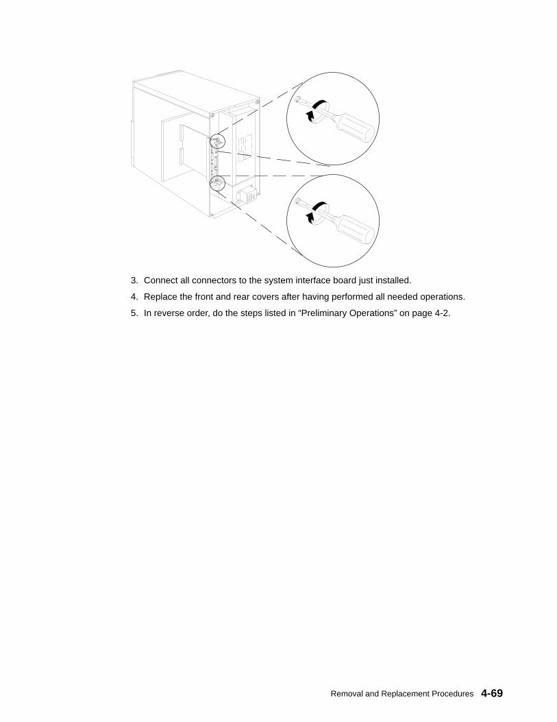
Removal and Replacement Procedures 4-69
3. Connect all connectors to the system interface board just installed.
4. Replace the front and rear covers after having performed all needed operations.
5. In reverse order, do the steps listed in “Preliminary Operations” on page 4-2.

Service Guide4-70
Base Unit CPU ModuleThis procedure describes removing and replacing the CPU Module in the base unit.
Removal1. Do the steps detailed in “Preliminary Operations” on page 4-2.
2. To access the CPU module, remove the rear cover from the unit, following theprocedures described on page 4-4.
1. Loosen the retaining screws shown in the figure using a screwdriver.
Base Unit, Rear
2. Using the CPU module puller as indicated in the following figure, unlock the CPU modulefrom the base unit.
Base Unit, Rear
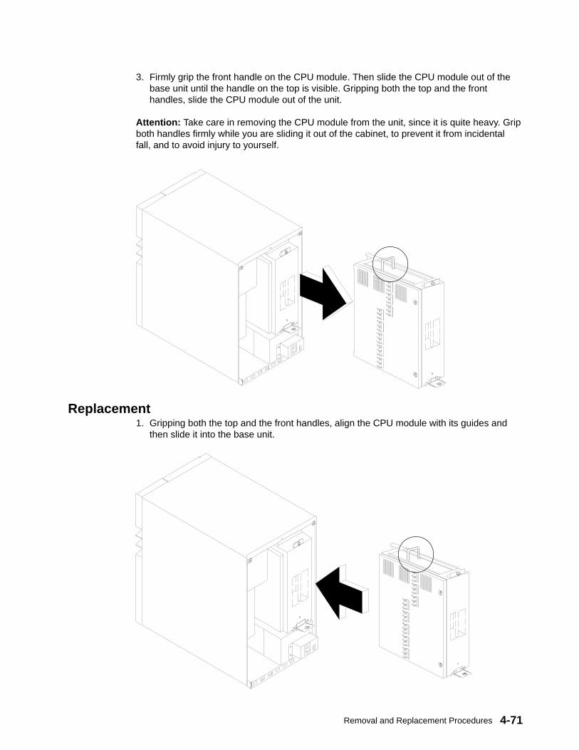
Removal and Replacement Procedures 4-71
3. Firmly grip the front handle on the CPU module. Then slide the CPU module out of thebase unit until the handle on the top is visible. Gripping both the top and the fronthandles, slide the CPU module out of the unit.
Attention: Take care in removing the CPU module from the unit, since it is quite heavy. Gripboth handles firmly while you are sliding it out of the cabinet, to prevent it from incidentalfall, and to avoid injury to yourself.
Replacement1. Gripping both the top and the front handles, align the CPU module with its guides and
then slide it into the base unit.
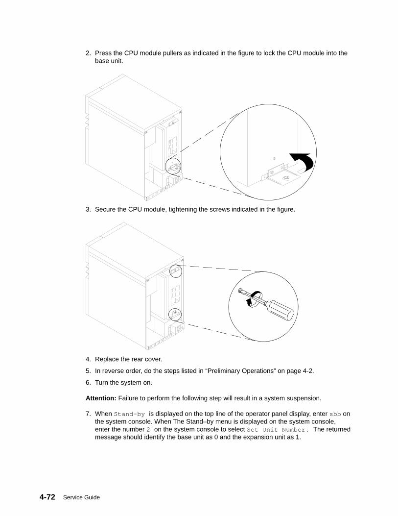
Service Guide4-72
2. Press the CPU module pullers as indicated in the figure to lock the CPU module into thebase unit.
3. Secure the CPU module, tightening the screws indicated in the figure.
4. Replace the rear cover.
5. In reverse order, do the steps listed in “Preliminary Operations” on page 4-2.
6. Turn the system on.
Attention: Failure to perform the following step will result in a system suspension.
7. When Stand–by is displayed on the top line of the operator panel display, enter sbb onthe system console. When The Stand–by menu is displayed on the system console,enter the number 2 on the system console to select Set Unit Number. The returnedmessage should identify the base unit as 0 and the expansion unit as 1.

Removal and Replacement Procedures 4-73
Base Unit I/O, CPU and Memory CardsThis procedure describes removing and replacing the I/O, CPU and Memory cards in theCPU module once it is removed from the base unit.
Note: It is strongly recommended that only experienced people remove the I/O, CPU, andmemory cards from the CPU module.
Removal1. Do the steps detailed in “Preliminary Operations” on page 4-2.
2. Remove the CPU module from the base unit, following the procedure described on page4-70.
3. Position the CPU module as illustrated in the following figure. Loosen the two retainingscrews used to lock the cover.
J50 Retaining Screws
4. Pull the CPU module cover up, inclining it as illustrated in the figure (A). Then pull thecover out of the CPU box (B).
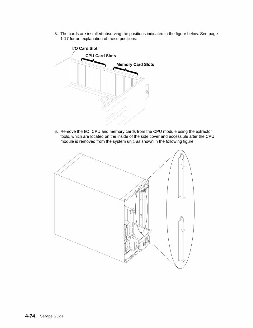
Service Guide4-74
5. The cards are installed observing the positions indicated in the figure below. See page1-17 for an explanation of these positions.
Memory Card Slots
CPU Card Slots
I/O Card Slot
6. Remove the I/O, CPU and memory cards from the CPU module using the extractortools, which are located on the inside of the side cover and accessible after the CPUmodule is removed from the system unit, as shown in the following figure.
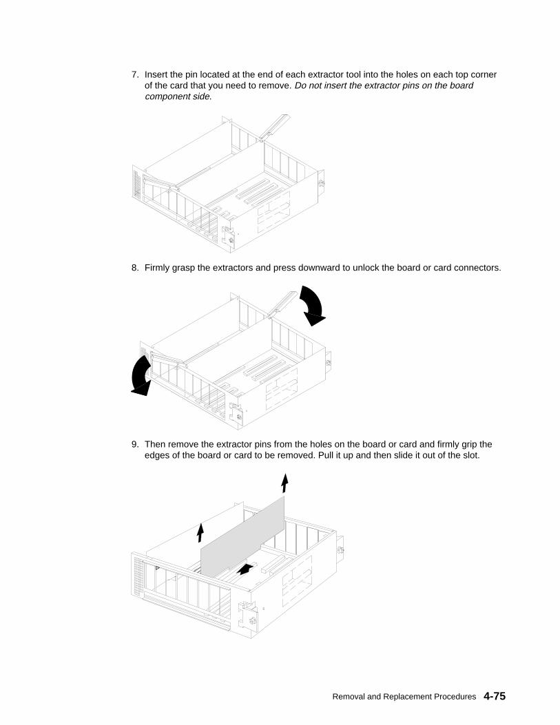
Removal and Replacement Procedures 4-75
7. Insert the pin located at the end of each extractor tool into the holes on each top cornerof the card that you need to remove. Do not insert the extractor pins on the boardcomponent side.
8. Firmly grasp the extractors and press downward to unlock the board or card connectors.
9. Then remove the extractor pins from the holes on the board or card and firmly grip theedges of the board or card to be removed. Pull it up and then slide it out of the slot.
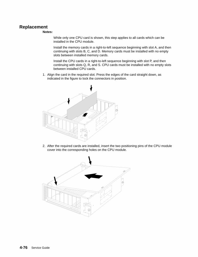
Service Guide4-76
ReplacementNotes:
While only one CPU card is shown, this step applies to all cards which can beinstalled in the CPU module.
Install the memory cards in a right-to-left sequence beginning with slot A, and thencontinuing with slots B, C, and D. Memory cards must be installed with no emptyslots between installed memory cards.
Install the CPU cards in a right-to-left sequence beginning with slot P, and thencontinuing with slots Q, R, and S. CPU cards must be installed with no empty slotsbetween installed CPU cards.
1. Align the card in the required slot. Press the edges of the card straight down, asindicated in the figure to lock the connectors in position.
2. After the required cards are installed, insert the two positioning pins of the CPU modulecover into the corresponding holes on the CPU module.

Removal and Replacement Procedures 4-77
3. Push the cover down.
4. Secure the cover, tightening the retaining screws indicated in the figure.
J50 Retaining Screws
Attention: Before inserting the CPU module into the base unit, and before re-starting thesystem, make sure you have securely closed the cover of the CPU module.
5. Replace the CPU module in the base unit, following the procedure described on page4-71.
6. In reverse order, do the steps listed in “Preliminary Operations” on page 4-2.
7. Turn the system on.
Attention: Failure to perform the following step will result in a system suspension.
8. When Stand–by is displayed on the top line of the operator panel display, enter sbb onthe system console. When The Stand–by menu is displayed on the system console,enter the number 2 on the system console to select Set Unit Number. The returnedmessage should identify the base unit as 0 and the expansion unit as 1.

Service Guide4-78
Memory ModulesThis procedure describes removing and replacing memory modules from memory cards inthe CPU module once it is removed from the base unit.
Note: There are four types of memory cards as shown below
Removal1. Do the steps detailed in “Preliminary Operations” on page 4-2.
2. Remove the CPU module from the base unit, following the procedure described on page4-70.
3. Remove the appropriate memory card from the CPU module, as described in “I/O, CPUand Memory Cards” on page 4-73.
Memory card memory module positions vary and are numbered as follows:
Base MRX Memory Card1...4
Bank 0
Bank 0
Bank 1
Bank 15...8
Bank 0
Bank 0
Bank 1
Bank 1
1...4
5...8
Two Bank RLX Memory Card
Bank 0
Bank 0
Bank 1
Bank 1
Bank 0
Bank 0
Bank 1
Bank 1
1...8
9...16
Four Bank NFX Memory Card
Bank 0
Bank 0Bank 3
Bank 3Bank 1Bank 2Bank 1Bank 2
Bank 0
Bank 0Bank 3
Bank 3Bank 1Bank 2Bank 1Bank 2

Removal and Replacement Procedures 4-79
SF5 Memory Card1...8
9...16Bank 0
Bank 0Bank 3
Bank 3Bank 1Bank 2Bank 1Bank 2
Bank 0
Bank 0Bank 3
Bank 3Bank 1Bank 2Bank 1Bank 2
4. Press the release lever on the connector to unseat the memory module.
5. Grip the edges of the memory module and firmly pull it out of the memory card.
Replacement1. Place the memory module on the appropriate connector on the memory card; then firmly
press the memory module into this connector.
Release Lever
2. In reverse order, do the steps listed in “Removal” on page 4-78.

Service Guide4-80
System PlanarThis procedure describes removing and replacing the system planar in the CPU moduleonce it is removed from the base unit.
Removal1. Do the steps detailed in “Preliminary Operations” on page 4-2.
2. Remove the CPU module from the base unit, following the procedure described on page4-70.
3. Remove all cards installed on the system planar, as described in “I/O, CPU and MemoryCards” on page 4-73.
4. Remove the stiffener bar of the system planar unscrewing the retaining screws shown inthe figure.
5. Unscrew the retaining screws used to secure the system planar to the CPU module, asshown in the figure.
6. Pull the system planar out of the CPU module.
CPU Module
SystemPlanar
StiffenerBar
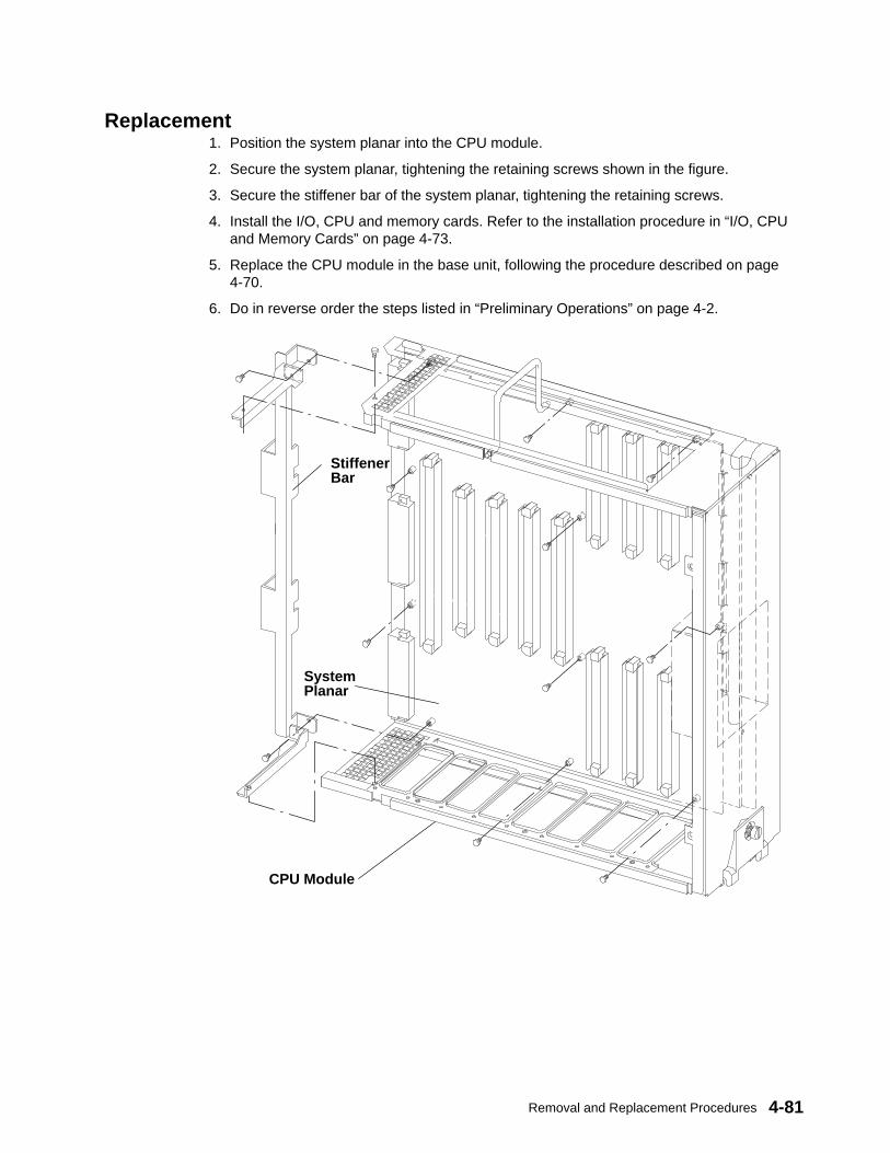
Removal and Replacement Procedures 4-81
Replacement1. Position the system planar into the CPU module.
2. Secure the system planar, tightening the retaining screws shown in the figure.
3. Secure the stiffener bar of the system planar, tightening the retaining screws.
4. Install the I/O, CPU and memory cards. Refer to the installation procedure in “I/O, CPUand Memory Cards” on page 4-73.
5. Replace the CPU module in the base unit, following the procedure described on page4-70.
6. Do in reverse order the steps listed in “Preliminary Operations” on page 4-2.
CPU Module
SystemPlanar
StiffenerBar
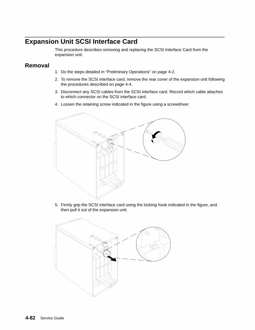
Service Guide4-82
Expansion Unit SCSI Interface CardThis procedure describes removing and replacing the SCSI Interface Card from theexpansion unit.
Removal1. Do the steps detailed in “Preliminary Operations” on page 4-2.
2. To remove the SCSI interface card, remove the rear cover of the expansion unit followingthe procedures described on page 4-4.
3. Disconnect any SCSI cables from the SCSI interface card. Record which cable attachesto which connector on the SCSI interface card.
4. Loosen the retaining screw indicated in the figure using a screwdriver.
5. Firmly grip the SCSI interface card using the locking hook indicated in the figure, andthen pull it out of the expansion unit.
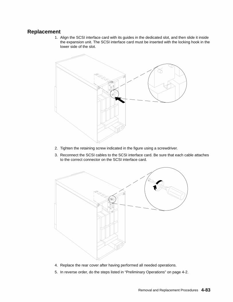
Removal and Replacement Procedures 4-83
Replacement1. Align the SCSI interface card with its guides in the dedicated slot, and then slide it inside
the expansion unit. The SCSI interface card must be inserted with the locking hook in thelower side of the slot.
2. Tighten the retaining screw indicated in the figure using a screwdriver.
3. Reconnect the SCSI cables to the SCSI interface card. Be sure that each cable attachesto the correct connector on the SCSI interface card.
4. Replace the rear cover after having performed all needed operations.
5. In reverse order, do the steps listed in “Preliminary Operations” on page 4-2.

Service Guide4-84
Base Unit First SCSI Bus Connection
Disconnection1. Do the steps detailed in “Preliminary Operations” on page 4-2.
2. Remove the rear, front, and top covers of the unit following the procedures describedrespectively on pages 4-4, 4-7, and 4-10.
3. Remove the CPU module from the base unit, following the procedure in “CPU Module”on page 4-70.
4. Ensure that each SCSI controller is installed in the correct position in the MCA cardcage. For detailed information, see “SCSI Controllers” on page 1-28.
5. Disconnect the SCSI cable from the first SCSI-2 differential fast/wide controller installedin the base unit MCA card cage.
6. Disconnect the other end of the SCSI cable from the P02 connector on the base unitback plane. Also, disconnect the ground cable from the back plane, as shown in sectionC of the diagram on page 4-84.
7. Pry the SCSI cable retainer from the top of the unit.
8. Remove the SCSI cable, taking it out of the cable fasteners located at the top of the unit,and sliding it out of the unit.
ConnectionTo activate the first SCSI bus in the base unit using the SCSI cable, part number 19H0398.
1. Connect the ribbon connector of the SCSI cable to the first SCSI-2 differential fast/widecontroller installed in the base unit MCA card cage. Using a screwdriver, secure thisconnector by tightening the designated screws. (See section A of the diagram on page4-84).
2. Route the SCSI cable the same as the one just removed, securing it to the unit using thecable fasteners located on the top of the unit. (See section B of the diagram on page4-84).
3. Replace the SCSI cable retainer to the top of the unit.
4. Connect the other end of the SCSI cable to the connector marked P02 on the base unitback plane, and do the ground connection, as shown in section C of the diagram onpage 4-84. Be sure that the SCSI cable route does not interfere with the FXE cableconnection on the back plane.
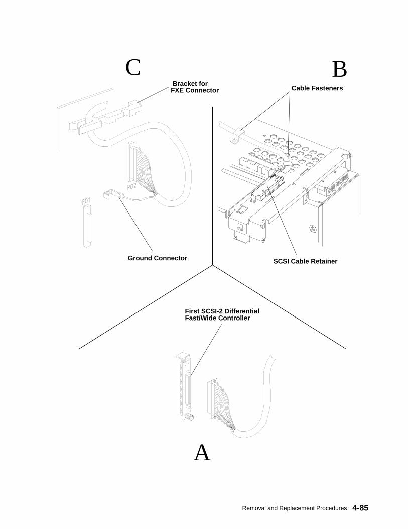
Removal and Replacement Procedures 4-85
B
A
C Bracket forFXE Connector
First SCSI-2 DifferentialFast/Wide Controller
Ground Connector
Cable Fasteners
SCSI Cable Retainer
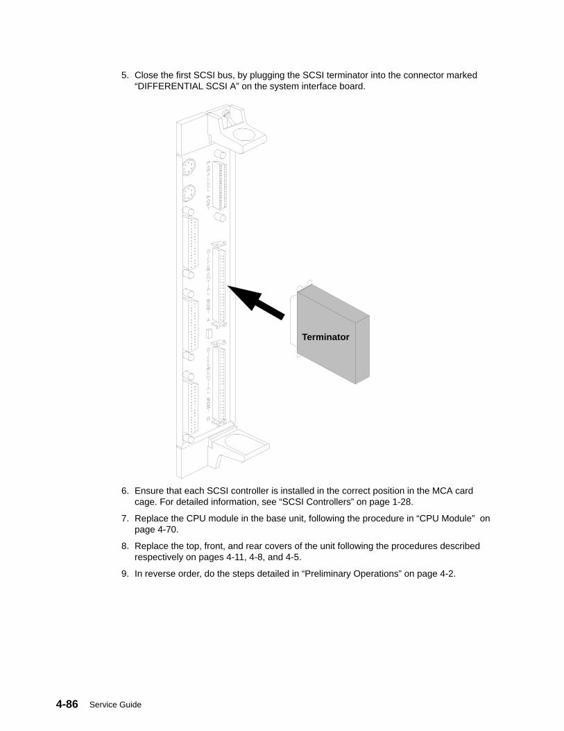
Service Guide4-86
5. Close the first SCSI bus, by plugging the SCSI terminator into the connector marked“DIFFERENTIAL SCSI A” on the system interface board.
Terminator
6. Ensure that each SCSI controller is installed in the correct position in the MCA cardcage. For detailed information, see “SCSI Controllers” on page 1-28.
7. Replace the CPU module in the base unit, following the procedure in “CPU Module” onpage 4-70.
8. Replace the top, front, and rear covers of the unit following the procedures describedrespectively on pages 4-11, 4-8, and 4-5.
9. In reverse order, do the steps detailed in “Preliminary Operations” on page 4-2.
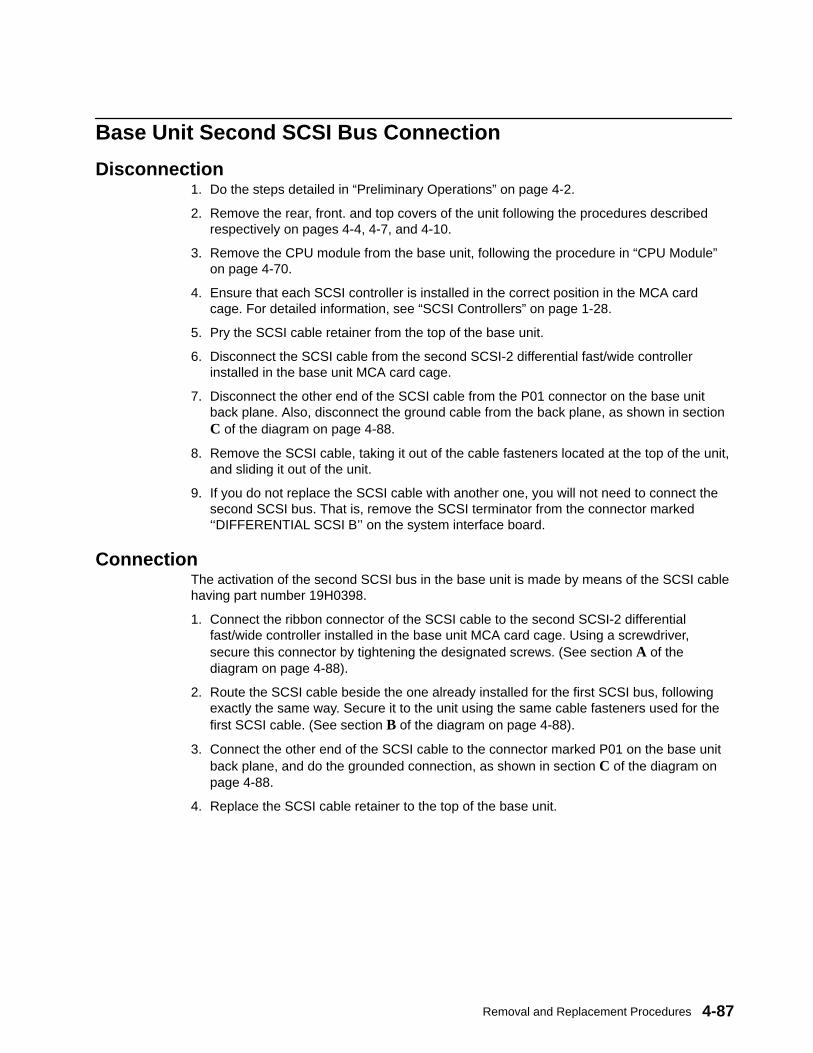
Removal and Replacement Procedures 4-87
Base Unit Second SCSI Bus Connection
Disconnection1. Do the steps detailed in “Preliminary Operations” on page 4-2.
2. Remove the rear, front. and top covers of the unit following the procedures describedrespectively on pages 4-4, 4-7, and 4-10.
3. Remove the CPU module from the base unit, following the procedure in “CPU Module”on page 4-70.
4. Ensure that each SCSI controller is installed in the correct position in the MCA cardcage. For detailed information, see “SCSI Controllers” on page 1-28.
5. Pry the SCSI cable retainer from the top of the base unit.
6. Disconnect the SCSI cable from the second SCSI-2 differential fast/wide controllerinstalled in the base unit MCA card cage.
7. Disconnect the other end of the SCSI cable from the P01 connector on the base unitback plane. Also, disconnect the ground cable from the back plane, as shown in sectionC of the diagram on page 4-88.
8. Remove the SCSI cable, taking it out of the cable fasteners located at the top of the unit,and sliding it out of the unit.
9. If you do not replace the SCSI cable with another one, you will not need to connect thesecond SCSI bus. That is, remove the SCSI terminator from the connector marked‘‘DIFFERENTIAL SCSI B’’ on the system interface board.
ConnectionThe activation of the second SCSI bus in the base unit is made by means of the SCSI cablehaving part number 19H0398.
1. Connect the ribbon connector of the SCSI cable to the second SCSI-2 differentialfast/wide controller installed in the base unit MCA card cage. Using a screwdriver,secure this connector by tightening the designated screws. (See section A of thediagram on page 4-88).
2. Route the SCSI cable beside the one already installed for the first SCSI bus, followingexactly the same way. Secure it to the unit using the same cable fasteners used for thefirst SCSI cable. (See section B of the diagram on page 4-88).
3. Connect the other end of the SCSI cable to the connector marked P01 on the base unitback plane, and do the grounded connection, as shown in section C of the diagram onpage 4-88.
4. Replace the SCSI cable retainer to the top of the base unit.
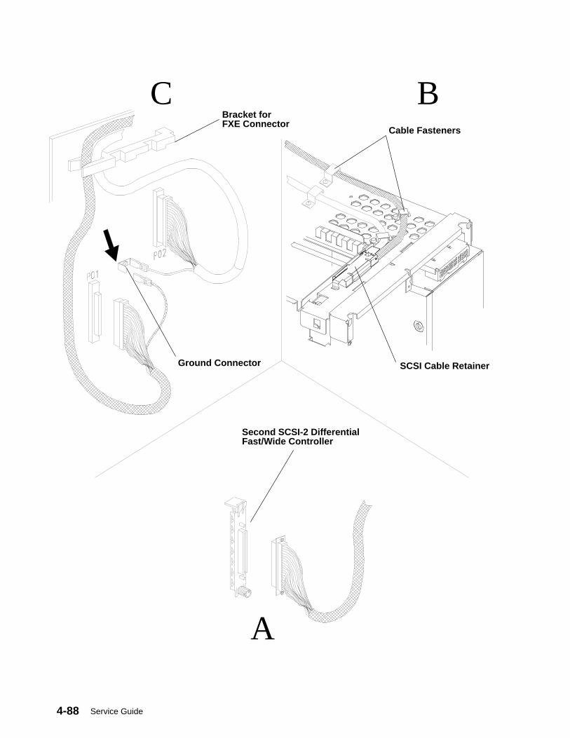
Service Guide4-88
B
A
CBracket forFXE Connector
Second SCSI-2 DifferentialFast/Wide Controller
Cable Fasteners
Ground Connector SCSI Cable Retainer
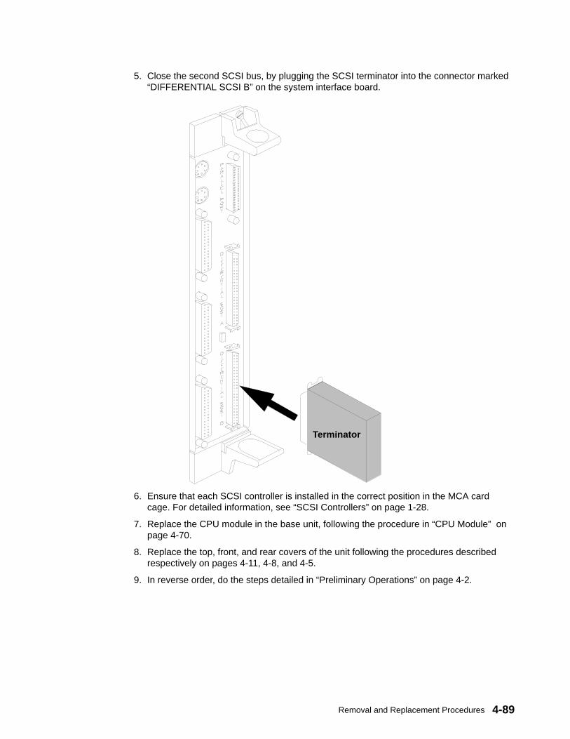
Removal and Replacement Procedures 4-89
5. Close the second SCSI bus, by plugging the SCSI terminator into the connector marked“DIFFERENTIAL SCSI B” on the system interface board.
Terminator
6. Ensure that each SCSI controller is installed in the correct position in the MCA cardcage. For detailed information, see “SCSI Controllers” on page 1-28.
7. Replace the CPU module in the base unit, following the procedure in “CPU Module” onpage 4-70.
8. Replace the top, front, and rear covers of the unit following the procedures describedrespectively on pages 4-11, 4-8, and 4-5.
9. In reverse order, do the steps detailed in “Preliminary Operations” on page 4-2.
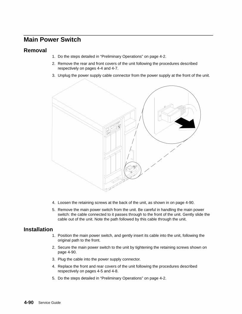
Service Guide4-90
Main Power Switch
Removal1. Do the steps detailed in “Preliminary Operations” on page 4-2.
2. Remove the rear and front covers of the unit following the procedures describedrespectively on pages 4-4 and 4-7.
3. Unplug the power supply cable connector from the power supply at the front of the unit.
4. Loosen the retaining screws at the back of the unit, as shown in on page 4-90.
5. Remove the main power switch from the unit. Be careful in handling the main powerswitch: the cable connected to it passes through to the front of the unit. Gently slide thecable out of the unit. Note the path followed by this cable through the unit.
Installation1. Position the main power switch, and gently insert its cable into the unit, following the
original path to the front.
2. Secure the main power switch to the unit by tightening the retaining screws shown onpage 4-90.
3. Plug the cable into the power supply connector.
4. Replace the front and rear covers of the unit following the procedures describedrespectively on pages 4-5 and 4-8.
5. Do the steps detailed in “Preliminary Operations” on page 4-2.
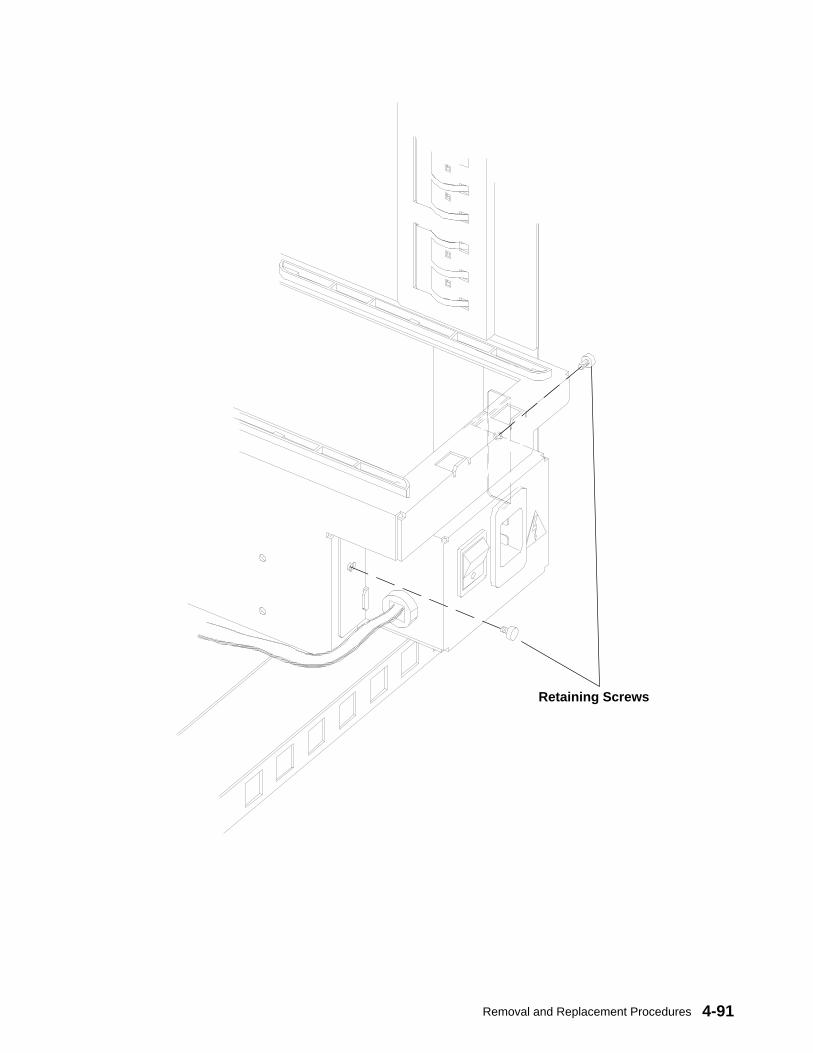
Removal and Replacement Procedures 4-91
Retaining Screws
Service Guide4-92
Base Unit FXB Flex CableThis procedure describes how to remove and replace the FXB flex cable located inside thebase unit.
Removal1. Do the steps detailed in “Preliminary Operations” on page 4-2.
2. To access the FXB flex cable, remove the rear, front, and top covers of the base unitfollowing the procedures described respectively on pages 4-4, 4-7, and 4-10.
3. Pull the CPU module out about six inches, following the procedures described on page4-70.
4. Disconnect the FXB cable MICROPAX connector from the connector marked U126/Y1on the PMA board in the base unit MCA card cage.
5. Loosen the retaining screw locking the connector of the FXB cable to the base unit backplane mechanical support.
6. Slide the connector of the FXB cable in the appropriate direction, then remove it from theunit.
Note: The diagram on page 4-93 shows the location of the FXB cable connector in thebase unit
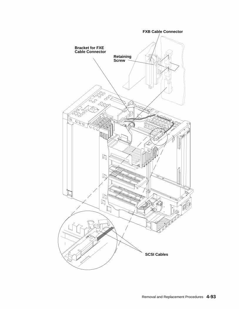
Removal and Replacement Procedures 4-93
FXB Cable Connector
RetainingScrew
Bracket for FXECable Connector
SCSI Cables

Service Guide4-94
Replacement1. Insert the connector of the FXB cable into the vertical mechanical support located in the
rear of the back plane.
2. Slide the connector of the FXB cable, then secure it to the back plane connector supportby tightening the retaining screw.
3. Connect the FXB cable MICROPAX connector to the connector marked U126/Y1 on thePMA board in the base unit MCA card cage.
4. Adjust the slack from the SCSI cables that are routed over the top of the base unit. Thiswill make replacement of the CPU module easier.
5. Replace the CPU module, reverse the procedure found on page 4-70.
6. Replace the top, front, and rear covers following the procedures described respectivelyon pages 4-10, 4-7, and 4-4.
7. In reverse order, do the steps listed in “Preliminary Operations” on page 4-2.
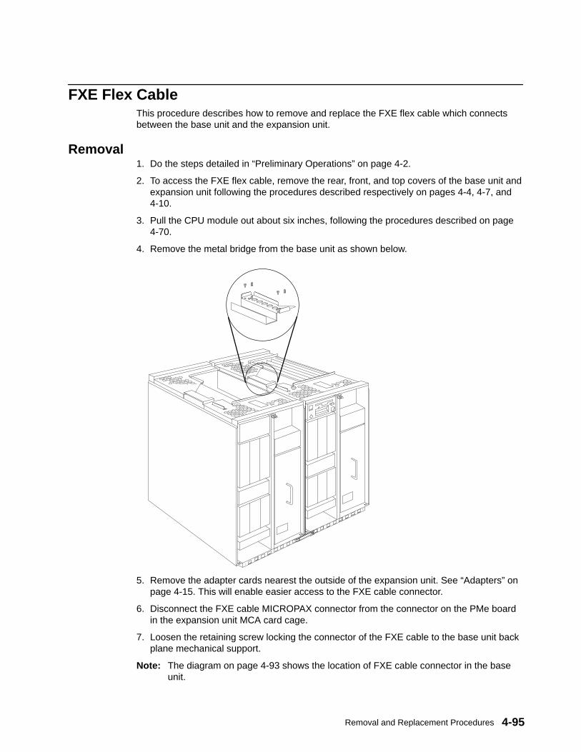
Removal and Replacement Procedures 4-95
FXE Flex CableThis procedure describes how to remove and replace the FXE flex cable which connectsbetween the base unit and the expansion unit.
Removal1. Do the steps detailed in “Preliminary Operations” on page 4-2.
2. To access the FXE flex cable, remove the rear, front, and top covers of the base unit andexpansion unit following the procedures described respectively on pages 4-4, 4-7, and4-10.
3. Pull the CPU module out about six inches, following the procedures described on page4-70.
4. Remove the metal bridge from the base unit as shown below.
5. Remove the adapter cards nearest the outside of the expansion unit. See “Adapters” onpage 4-15. This will enable easier access to the FXE cable connector.
6. Disconnect the FXE cable MICROPAX connector from the connector on the PMe boardin the expansion unit MCA card cage.
7. Loosen the retaining screw locking the connector of the FXE cable to the base unit backplane mechanical support.
Note: The diagram on page 4-93 shows the location of FXE cable connector in the baseunit.

Service Guide4-96
8. Slide the connector of the FXE cable as shown and remove it through the slit highlightedwith a circle below.
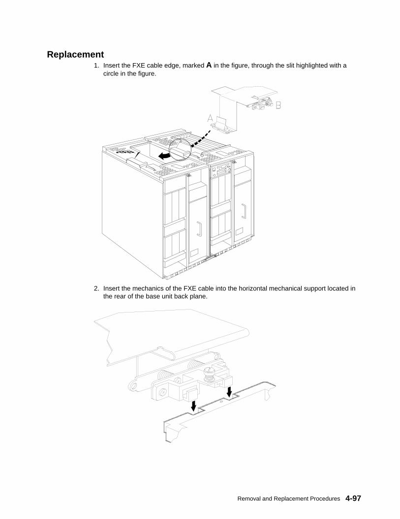
Removal and Replacement Procedures 4-97
Replacement1. Insert the FXE cable edge, marked A in the figure, through the slit highlighted with a
circle in the figure.
2. Insert the mechanics of the FXE cable into the horizontal mechanical support located inthe rear of the base unit back plane.
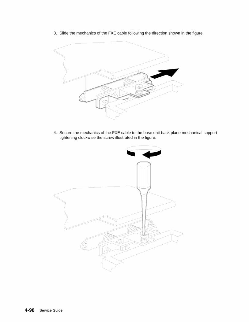
Service Guide4-98
3. Slide the mechanics of the FXE cable following the direction shown in the figure.
4. Secure the mechanics of the FXE cable to the base unit back plane mechanical supporttightening clockwise the screw illustrated in the figure.
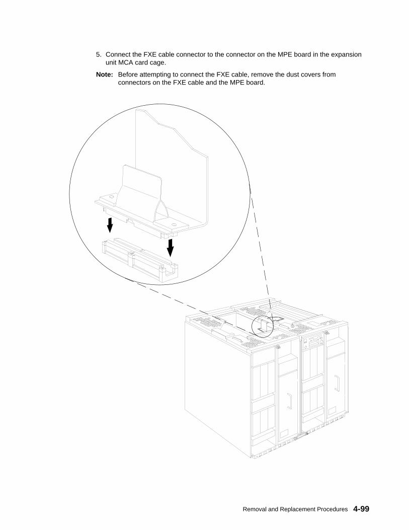
Removal and Replacement Procedures 4-99
5. Connect the FXE cable connector to the connector on the MPE board in the expansionunit MCA card cage.
Note: Before attempting to connect the FXE cable, remove the dust covers fromconnectors on the FXE cable and the MPE board.
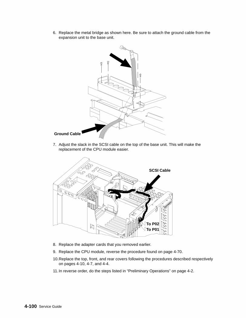
Service Guide4-100
6. Replace the metal bridge as shown here. Be sure to attach the ground cable from theexpansion unit to the base unit.
Ground Cable
7. Adjust the slack in the SCSI cable on the top of the base unit. This will make thereplacement of the CPU module easier.
To P02To P01
SCSI Cable
8. Replace the adapter cards that you removed earlier.
9. Replace the CPU module, reverse the procedure found on page 4-70.
10.Replace the top, front, and rear covers following the procedures described respectivelyon pages 4-10, 4-7, and 4-4.
11. In reverse order, do the steps listed in “Preliminary Operations” on page 4-2.
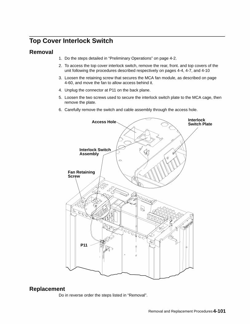
Removal and Replacement Procedures 4-101
Top Cover Interlock Switch
Removal1. Do the steps detailed in “Preliminary Operations” on page 4-2.
2. To access the top cover interlock switch, remove the rear, front. and top covers of theunit following the procedures described respectively on pages 4-4, 4-7, and 4-10
3. Loosen the retaining screw that secures the MCA fan module, as described on page4-60, and move the fan to allow access behind it.
4. Unplug the connector at P11 on the back plane.
5. Loosen the two screws used to secure the interlock switch plate to the MCA cage, thenremove the plate.
6. Carefully remove the switch and cable assembly through the access hole.
Interlock SwitchAssembly
InterlockSwitch Plate
P11
Access Hole
Fan RetainingScrew
ReplacementDo in reverse order the steps listed in “Removal”.
Service Guide4-102
Back PlaneAttention: After the back plane is installed and the system is powered–up, the system ID isdown-loaded to the back plane from a backup source within the system. This ID becomespermanent on the back plane and cannot be altered without special tools. Therefore, theback plane cannot be transferred to another system. It must be returned to the plant ofmanufacture as a new defective.
Attention: The back plane and system interface board EEPROMs contain the SYSID of thesystem. When one of the two components is to be replaced (for example the back plane),the SYSID information will be copied from operator panel EEPROMs into the back planeEEPROMs when you start the system.
To avoid loosing this information, it is not possible to replace both components at the sametime.When both components are to be replaced, proceed as follows:
1. First substitute the system interface board and start up the system: the SYSIDinformation will be copied from back plane EEPROM to the system interface boardEEPROM.
2. Substitute the back plane and start up the system: the SYSID information will be copiedfrom the system interface board EEPROM to the back plane EEPROM.
Removal1. Do the steps detailed in “Preliminary Operations” on page 4–2.
2. Remove the rear, front, and top covers of the cabinet following the procedures describedrespectively on pages 4–4, 4–7 and 4–10.
3. Remove both the left and the right side covers, as shown on page 4–13.
4. Remove the operator panel, as shown on page 4–26.
5. Remove any internal media device, as shown on page 4–34.
6. Remove any internal disk drive located in the front of the unit, as shown on page 4–39.
7. Remove the power supply, as shown on page 4–50.
8. To access the unit from the front, disconnect any internal cable connected to the front orrear side of the back plane.
9. Remove the CPU module, as shown on page 4–67.
10.Remove the bar used to lock the front cover to the unit, unscrewing the retaining screw,as shown on page 4-103, and sliding it out of the unit from the front.
This step is needed only if you decide to remove the back plane sliding it out of the topside of the unit.
11.Remove the MCA card cage, following the procedure described on page 4–24.
12.Remove any internal disk drive located in the rear of the unit, as shown on page 4–39.
13.Remove the system interface board, as shown on page 4–65.
14.Remove the support bar of the system interface board, unscrewing the designatedscrews as shown on page 4-103.
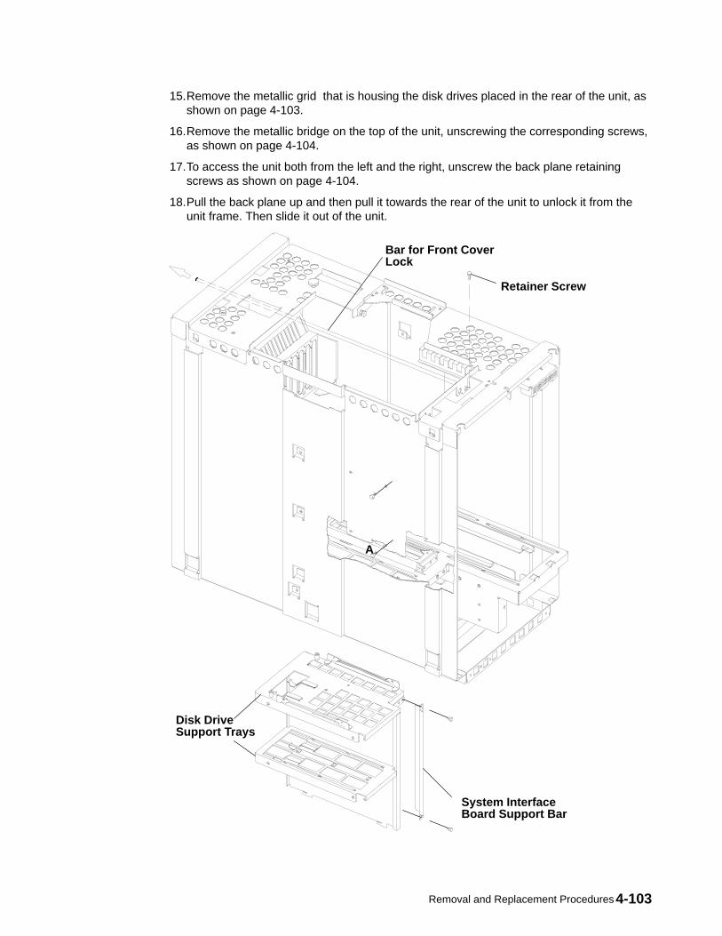
Removal and Replacement Procedures 4-103
15.Remove the metallic grid that is housing the disk drives placed in the rear of the unit, asshown on page 4-103.
16.Remove the metallic bridge on the top of the unit, unscrewing the corresponding screws,as shown on page 4-104.
17.To access the unit both from the left and the right, unscrew the back plane retainingscrews as shown on page 4-104.
18.Pull the back plane up and then pull it towards the rear of the unit to unlock it from theunit frame. Then slide it out of the unit.
Bar for Front CoverLock
System InterfaceBoard Support Bar
Disk DriveSupport Trays
A
Retainer Screw

Service Guide4-104
RetainingScrews
Back Plane
Metal Bridge
Replacement1. To replace the back plane, follow the removal procedure on page 4-102 in the reverse
order.
2. If the maintenance contract is signed and still valid, after having replaced the new backplane remember to reset the appropriate flags to enable the maintenance features.
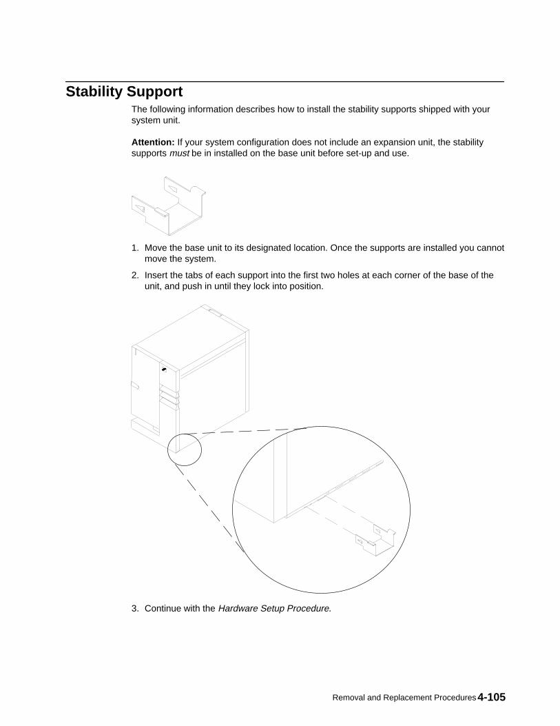
Removal and Replacement Procedures 4-105
Stability SupportThe following information describes how to install the stability supports shipped with yoursystem unit.
Attention: If your system configuration does not include an expansion unit, the stabilitysupports must be in installed on the base unit before set-up and use.
1. Move the base unit to its designated location. Once the supports are installed you cannotmove the system.
2. Insert the tabs of each support into the first two holes at each corner of the base of theunit, and push in until they lock into position.
3. Continue with the Hardware Setup Procedure.

Service Guide4-106

Parts Information 5-1
Chapter 5. Parts Information
Acronyms for FRU PartsOccasionally, an acronym is displayed with an SRN or Error Code on the LCD display toidentify a failing FRU. The listing below defines the FRUs associated with the acronymsdisplayed.
Acronym Associated FRU
C1D 601 processor card
C4D 604 processor card
X4D 604E processor card
MR2 MR2 memory card
MR4 MR4 memory card
MRE MRE memory card
NFX NFX memory card
SFX SFX memory card
MPB System planar (J30, J40)
NMB System planar (J50)
SIF X System interface board
PMA 7 Slot Micro Channel adapter planar, base
PME 8 Slot Micro Channel adapter planar, expansion
IOD I/O card
BIO I/O card
OPP Operator panel
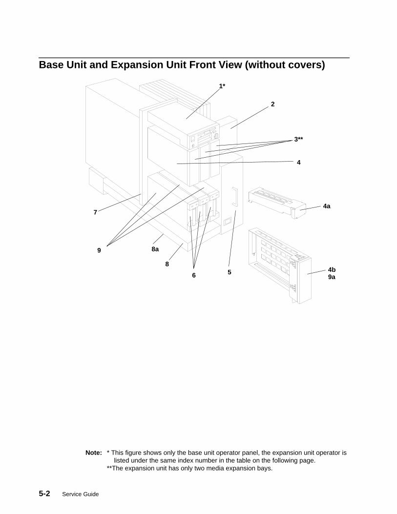
5-2 Service Guide
Base Unit and Expansion Unit Front View (without covers)
1*
2
3**
4
56
8
9
4a
4b9a
8a
7
Note: * This figure shows only the base unit operator panel, the expansion unit operator is listed under the same index number in the table on the following page.**The expansion unit has only two media expansion bays.
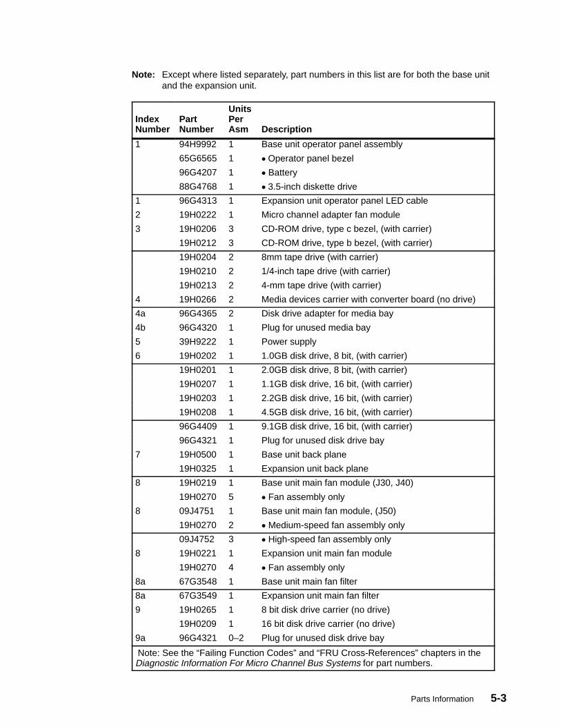
Parts Information 5-3
Note: Except where listed separately, part numbers in this list are for both the base unitand the expansion unit.
IndexNumber
PartNumber
UnitsPerAsm Description
1 94H9992 1 Base unit operator panel assembly
65G6565 1 � Operator panel bezel
96G4207 1 � Battery
88G4768 1 � 3.5-inch diskette drive
1 96G4313 1 Expansion unit operator panel LED cable
2 19H0222 1 Micro channel adapter fan module
3 19H0206 3 CD-ROM drive, type c bezel, (with carrier)
19H0212 3 CD-ROM drive, type b bezel, (with carrier)
19H0204 2 8mm tape drive (with carrier)
19H0210 2 1/4-inch tape drive (with carrier)
19H0213 2 4-mm tape drive (with carrier)
4 19H0266 2 Media devices carrier with converter board (no drive)
4a 96G4365 2 Disk drive adapter for media bay
4b 96G4320 1 Plug for unused media bay
5 39H9222 1 Power supply
6 19H0202 1 1.0GB disk drive, 8 bit, (with carrier)
19H0201 1 2.0GB disk drive, 8 bit, (with carrier)
19H0207 1 1.1GB disk drive, 16 bit, (with carrier)
19H0203 1 2.2GB disk drive, 16 bit, (with carrier)
19H0208 1 4.5GB disk drive, 16 bit, (with carrier)
96G4409 1 9.1GB disk drive, 16 bit, (with carrier)
96G4321 1 Plug for unused disk drive bay
7 19H0500 1 Base unit back plane
19H0325 1 Expansion unit back plane
8 19H0219 1 Base unit main fan module (J30, J40)
19H0270 5 � Fan assembly only
8 09J4751 1 Base unit main fan module, (J50)
19H0270 2 � Medium-speed fan assembly only
09J4752 3 � High-speed fan assembly only
8 19H0221 1 Expansion unit main fan module
19H0270 4 � Fan assembly only
8a 67G3548 1 Base unit main fan filter
8a 67G3549 1 Expansion unit main fan filter
9 19H0265 1 8 bit disk drive carrier (no drive)
19H0209 1 16 bit disk drive carrier (no drive)
9a 96G4321 0–2 Plug for unused disk drive bay
Note: See the “Failing Function Codes” and “FRU Cross-References” chapters in theDiagnostic Information For Micro Channel Bus Systems for part numbers.

5-4 Service Guide
Base Unit Rear View (without covers)
1
2
3
4
56
7
6a
5a
8
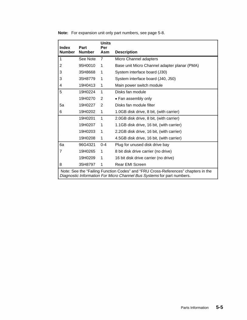
Parts Information 5-5
Note: For expansion unit only part numbers, see page 5-8.
IndexNumber
PartNumber
UnitsPerAsm Description
1 See Note 7 Micro Channel adapters
2 95H0010 1 Base unit Micro Channel adapter planar (PMA)
3 35H8668 1 System interface board (J30)
3 35H8779 1 System interface board (J40, J50)
4 19H0413 1 Main power switch module
5 19H0224 1 Disks fan module
19H0270 2 � Fan assembly only
5a 19H0227 2 Disks fan module filter
6 19H0202 1 1.0GB disk drive, 8 bit, (with carrier)
19H0201 1 2.0GB disk drive, 8 bit, (with carrier)
19H0207 1 1.1GB disk drive, 16 bit, (with carrier)
19H0203 1 2.2GB disk drive, 16 bit, (with carrier)
19H0208 1 4.5GB disk drive, 16 bit, (with carrier)
6a 96G4321 0-4 Plug for unused disk drive bay
7 19H0265 1 8 bit disk drive carrier (no drive)
19H0209 1 16 bit disk drive carrier (no drive)
8 35H8797 1 Rear EMI Screen
Note: See the “Failing Function Codes” and “FRU Cross-References” chapters in theDiagnostic Information For Micro Channel Bus Systems for part numbers.
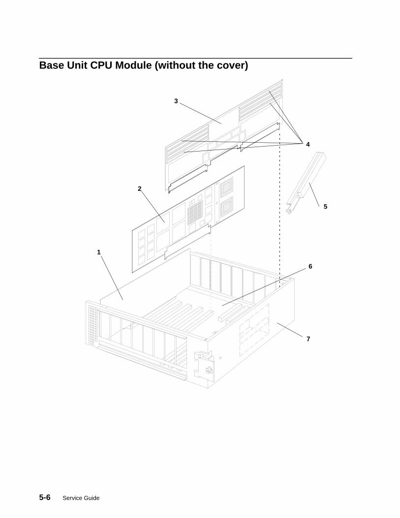
5-6 Service Guide
Base Unit CPU Module (without the cover)
1
2
3
4
5
6
7

Parts Information 5-7
IndexNumber
PartNumber
UnitsPerAsm Description
1 35H8780 1 I/O Card (J30, J40)
09J4760 1 I/O Card (J50)
2 35H8748 1-4 CPU card, type C1D 601 processor (J30)
09J4712 1-4 CPU card, type C4D 604 processor (J40)
93H6274 1-4 CPU card, type X4D 604E processor (J50)
3 19H0283 1-4 MR2 memory card (64 base) without memory modules
09J4779 1-4 MR4 memory card (256 base) without memory modules
93H4357 1-4 SF5 Memory card, base without memory modules
4 19H0240 8 Memory module, 8MB (MR2)
19H0271 8 Memory module, 32MB (MR4)
19H0287 4-16 Memory module, 8MB (NFX, RLX, or SF5)
19H0288 4-16 Memory module, 16MB (NFX, RLX, or SF5)
19H0289 4-16 Memory module, 32MB (NFX, RLX, or SF5)
35H8751 4-16 Memory module, 64MB (SF5)
5 96G4195 2 Card removal tool
6 19H0242 1 System planar MPB (J30)
35H8778 1 System planar MPB (J40)
19H0035 1 System planar NMB (J50)
7 19H0148 1 CPU module enclosure with cover (J30, J40)
67G3897 1 CPU module enclosure with cover (J50)
Note: The 7013 J Series systems can contain 601 based CPU cards, or 604 based CPUcards. CPU cards of different types cannot be mixed in the same system unit. Ensureany replacement processor card is compatible with the card that was removed.
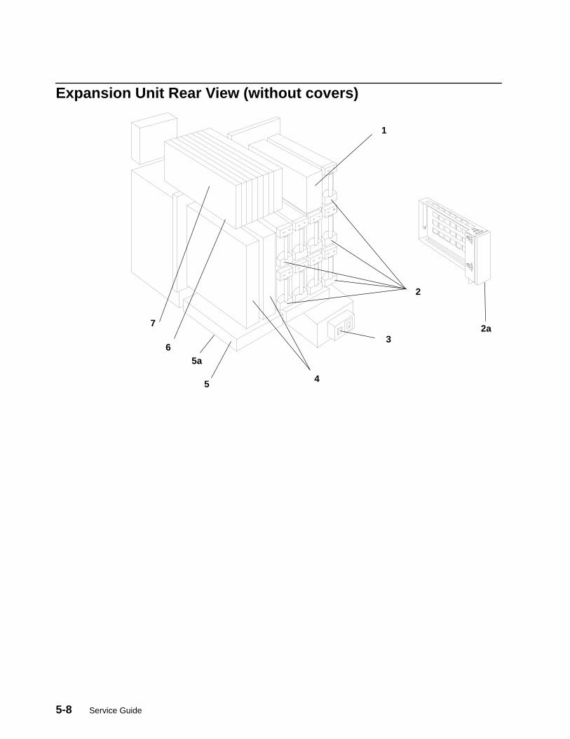
5-8 Service Guide
Expansion Unit Rear View (without covers)
1
2
3
4
5a6
7
5
2a
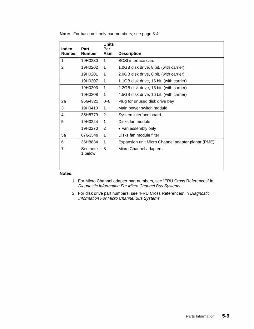
Parts Information 5-9
Note: For base unit only part numbers, see page 5-4.
IndexNumber
PartNumber
UnitsPerAsm Description
1 19H0230 1 SCSI interface card
2 19H0202 1 1.0GB disk drive, 8 bit, (with carrier)
19H0201 1 2.0GB disk drive, 8 bit, (with carrier)
19H0207 1 1.1GB disk drive, 16 bit, (with carrier)
19H0203 1 2.2GB disk drive, 16 bit, (with carrier)
19H0208 1 4.5GB disk drive, 16 bit, (with carrier)
2a 96G4321 0–8 Plug for unused disk drive bay
3 19H0413 1 Main power switch module
4 35H8779 2 System interface board
5 19H0224 1 Disks fan module
19H0270 2 � Fan assembly only
5a 67G3549 1 Disks fan module filter
6 35H8834 1 Expansion unit Micro Channel adapter planar (PME)
7 See note1 below
8 Micro Channel adapters
Notes:
1. For Micro Channel adapter part numbers, see “FRU Cross References” inDiagnostic Information For Micro Channel Bus Systems.
2. For disk drive part numbers, see “FRU Cross References” in DiagnosticInformation For Micro Channel Bus Systems.
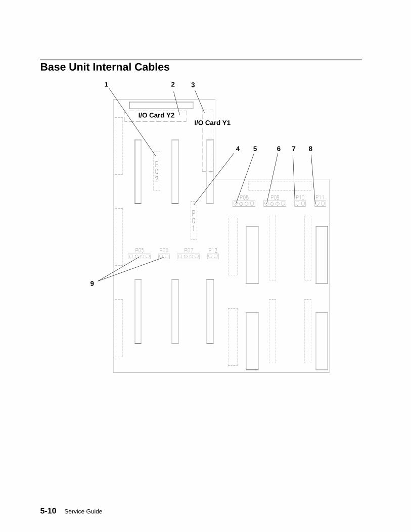
5-10 Service Guide
Base Unit Internal Cables
I/O Card Y2
1 2 3
4 5 6 7 8
9
I/O Card Y1

Parts Information 5-11
Note: For expansion unit part numbers, see page 5-12.
IndexNumber
PartNumber
UnitsPerAsm Description
1 19H0398 1 SCSI bus A input cable (P02, MCA slot 7)
2 19H0232 1 Expansion unit micro channel bus cable (FXE)
3 19H0231 1 Base unit micro channel bus cable (FXB)
4 19H0398 1 SCSI bus B input cable (P01, MCA slot 6)
5 67G3591 1 Disks fan module cable (P08)
6 96G4064 1 Micro channel adapter fan module cable (P09)
7 19H0365 1 Thermal sensor cable (P10)
8 67G3588 1 Top cover interlock switch cable (P11)
9 67G3592 1 Base unit fan cable (P05 and P06)
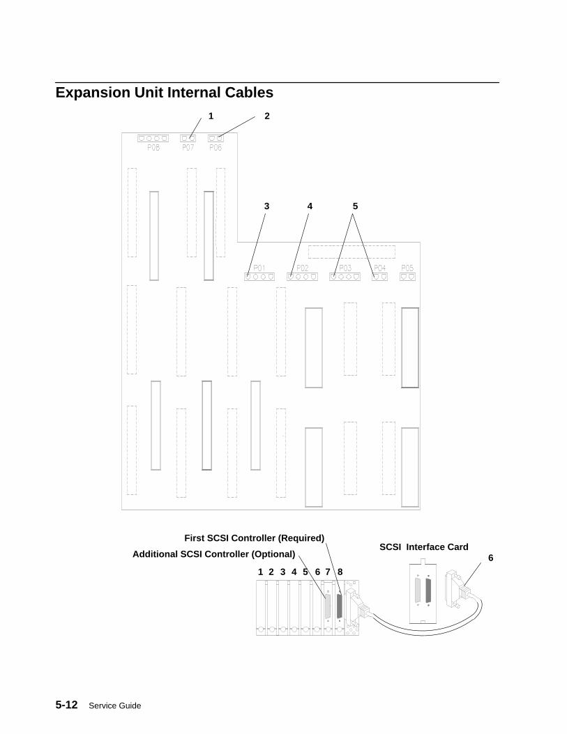
5-12 Service Guide
Expansion Unit Internal Cables1 2
3 4 5
85 6 71 2 3 4
Additional SCSI Controller (Optional)
First SCSI Controller (Required)SCSI Interface Card
6
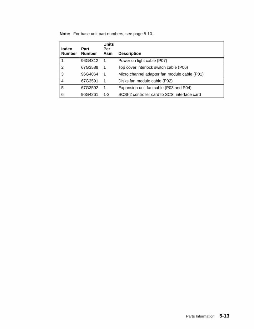
Parts Information 5-13
Note: For base unit part numbers, see page 5-10.
IndexNumber
PartNumber
UnitsPerAsm Description
1 96G4312 1 Power on light cable (P07)
2 67G3588 1 Top cover interlock switch cable (P06)
3 96G4064 1 Micro channel adapter fan module cable (P01)
4 67G3591 1 Disks fan module cable (P02)
5 67G3592 1 Expansion unit fan cable (P03 and P04)
6 96G4261 1-2 SCSI-2 controller card to SCSI interface card

5-14 Service Guide
Covers
2, 2a1
3
4
5
IndexNumber
PartNumber
UnitsPerAsm Description
1 8184701 1 Rear cover
2 19H0205 1 Replacement lockset (operator panel and rear cover)
2a 35H8650 1 Top cover interlock switch (inside the unit)
3 19H0439 1 Top cover
4 39H8919 1 Front cover (Includes front door)
5 67G3581 2 Side cover

Parts Information 5-15
Power Cables and Plugs
1 2 3 4
5 67
8 9
Index PartNumber
Country
1 14F1548 Bahamas, Barbados, Bolivia, Brazil, Canada, Costa Rica,Dominican Republic, El Salvador, Ecuador, Guatemala, Guyana,Haiti, Honduras, Jamaica, Japan, Netherlands Antilles, Panama,Peru, Philippines, Taiwan, Thailand, Trinidad, Tobago, U.S.A.(except Chicago), Venezuela
2 6427171 U.S.A. (Including Chicago)
2 6427168 Bahamas, Barbados, Bermuda, Bolivia, Brazil, Canada, CaymanIslands, Colombia, Costa Rica, Dominican Republic, Ecuador, ElSalvador, Guatemala, Guyana, Haiti, Honduras, Jamaica, Japan,Korea (South), Mexico, Netherlands Antilles, Nicaragua, Panama,Peru, Philippines, Puerto Rico, Saudi Arabia, Suriname, Trinidad,Taiwan, Venezuela
3 14F1559 Argentina, Australia, New Zealand,
4 14F1554 Abu Dhabi, Austria, Belgium, Bulgaria, Botswana, Denmark, Egypt,Finland, France, Germany, Greece, Iceland, Indonesia, Korea(South), Lebanon, Liechtenstein, Luxembourg, Macau, Netherlands,Norway, Portugal, Saudi Arabia, Spain, Sudan, Sweden,Switzerland, Turkey, Yugoslavia
5 14F1557 Bangladesh, Burma, Pakistan, South Africa, Sri Lanka
6 11H5086 Bahrain, Bermuda, Brunei, Channel Islands, Cyprus, Ghana, HongKong, India, Iraq, Ireland, Jordan, Kenya, Kuwait, Malawi, Malaysia,Nigeria, Oman, People’s Republic of China, Qatar, Sierra Leone,Singapore, Tanzania, Uganda, United Arab Emirates (Dubai), UnitedKingdom, Zambia
7 14F1560 Chile, Ethiopia, Italy
8 14F1561 Israel
9 14F1559 Paraguay, Colombia, Uruguay

5-16 Service Guide
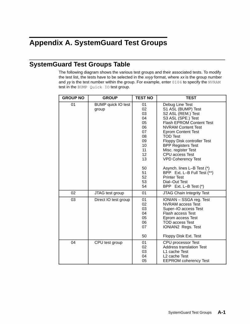
SystemGuard Test Groups A-1
Appendix A. SystemGuard Test Groups
SystemGuard Test Groups TableThe following diagram shows the various test groups and their associated tests. To modifythe test list, the tests have to be selected in the xxyy format, where xx is the group numberand yy is the test number within the group. For example, enter 0106 to specify the NVRAMtest in the BUMP Quick IO test group.
GROUP NO GROUP TEST NO TEST
01 BUMP quick IO testgroup
01020304050607080910111213
5051525354
Debug Line TestS1 ASL (BUMP) TestS2 ASL (REM.) Test S3 ASL (SPE.) TestFlash EPROM Content TestNVRAM Content TestEprom Content TestTOD TestFloppy Disk controller TestBPP Registers TestMisc. register TestCPU access TestVPD Coherency Test
Asynch. lines L–B Test (*)BPP Ext. L–B Full Test (**)Printer TestDial–Out TestBPP Ext. L–B Test (*)
02 JTAG test group 01 JTAG Chain Integrity Test
03 Direct IO test group 01020304050607
50
IONIAN – SSGA reg. TestNVRAM access TestSuper–IO access TestFlash access TestEprom access TestTOD access TestIONIAN2 Regs. Test
Floppy Disk Ext. Test
04 CPU test group 0102030405
CPU processor TestAddress translation TestL1 cache TestL2 cache TestEEPROM coherency Test
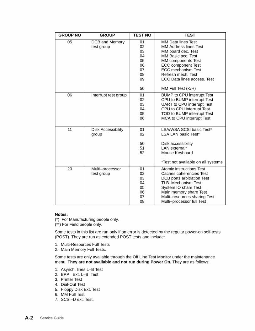
Service GuideA-2
GROUP NO TESTTEST NOGROUP
05 DCB and Memorytest group
010203040506070809
50
MM Data lines TestMM Address lines TestMM board dec. TestMM Basic acc. TestMM components TestECC component TestECC mechanism TestRefresh mech. TestECC Data lines access. Test
MM Full Test (K/H)
06 Interrupt test group 010203040506
BUMP to CPU interrupt TestCPU to BUMP interrupt TestUART to CPU interrupt TestCPU to CPU interrupt TestTOD to BUMP interrupt TestMCA to CPU interrupt Test
11 Disk Accessibilitygroup
0102
505152
LSA/WSA SCSI basic Test*LSA LAN basic Test*
Disk accessibilityLAN external*Mouse Keyboard
*Test not available on all systems
20 Multi–processortest group
0102030405060708
Atomic instructions TestCaches coherencies TestDCB ports arbitration TestTLB Mechanism TestSystem IO share TestMain memory share TestMulti–resources sharing TestMulti–processor full Test
Notes: (*) For Manufacturing people only.(**) For Field people only.
Some tests in this list are run only if an error is detected by the regular power-on self-tests(POST). They are run as extended POST tests and include:
1. Multi-Resources Full Tests2. Main Memory Full Tests.
Some tests are only available through the Off Line Test Monitor under the maintenancemenu. They are not available and not run during Power On. They are as follows:
1. Asynch. lines L–B Test2. BPP Ext. L–B Test3. Printer Test4. Dial-Out Test5. Floppy Disk Ext. Test6. MM Full Test7. SCSI–D ext. Test.
SystemGuard Test Groups A-3
SystemGuard Test Group DescriptionsThe following is a description of the different test groups and the tests available under them.All of these tests are performed automatically at Power On with default parameters. Theycan also be performed selectively (selection of test group/subtest/parameter) with userconfigured parameters, under the control of the Off Line Test monitor. This is available asone of the options in the Maintenance Menu under SystemGuard.
BUMP Quick I/O Tests GroupThese tests are performed by the BUMP and are launched at Power-On under the control ofOff Line Test monitor, under the Maintenance Menu. These tests check the accessibility and,the functions of the standard and direct I/O components from the BUMP. This group containsthe following list of tests.
Debug Asynchronous Line TestThis test checks the BUMP availability and access to the Flash EPROM. It consists of thefollowing sub-test.
Minimum Core Test This test is performed at Power On. A specific text on the Debugconsole is printed. The operator is required to check the result.
Service GuideA-4
BUMP, Remote, and Special Asynchronous Lines TestThese tests are meant to check the Asynchronous lines of the Standard I/O and theAsynchronous Lines controller in the Super I/O. These tests contain sub-tests, which aredescribed as follows. Each sub-test saves and restores the line parameters. When an erroris detected, it is reported to the operator with a suitable error message.
Internal Registers Test This test is performed at Power On and does Read / Write operationof approved values, in the Asynchronous lines register of the SuperI/O. The following registers are checked:
1. LCR2. SCR3. DLL4. DLM5. IER6. MCR.
Buffers Exchange TestThis test sends two ASCII characters in the following fourconfigurations and checks the received characters. This test is ininternal loop back mode and is performed at Power On. Thefollowing eight configurations are used:
1. 38400 bds 8 bits 2 stop Even parity2. 19200 bds 8 bits 2 stop Even parity3. 9600 bds 8 bits 2 stop Even parity4. 4800 bds 8 bits 2 stop Even parity5. 1200 bds 8 bits 2 stop Even parity6. 300 bds 8 bits 2 stop Even parity7. 150 bds 8 bits 2 stop Even parity8. 75 bds 8 bits 2 stop Even parity.
Junction Signals Test This test is also conducted in internal loop back mode and isperformed at Power On. The following loop backs are used:
1. RTS –> CTS2. DTR –> DSR3. OUT1 –> R14. OUT2 –> DCD.
Flash EPROM TestThis test checks the content of the Flash EPROM. It contains one sub-test:
Check-Sum Test In this test Flash EPROM is divided into different areas and AreaCRC is calculated. Then the Registered CRC is read and comparedwith the calculated CRC.
SystemGuard Test Groups A-5
NVRAM TestThis test checks the accessibility of NVRAM bytes. It contains the following sub-tests:
NVRAM Data Lines Access TestThis test saves the first NVRAM byte. Then a read / write operationis done word by word. It restores the first NVRAM byte.
NVRAM Address Lines Access TestThis test reads, writes and compares 2 NVRAM addresses. TheNVRAM addresses involved in this test are saved before testingand restored after testing.
Stack Area Read / Write TestThis test is for all stack area bytes. It saves the byte, conductsread/write operation and compares the written word with the readword. Then it restores the byte.
Permanent Data Areas TestThis test is performed for all permanent data areas with anassociated check sum. Data area check sum is calculated and iscompared with the registered check sum.
EPROM TestThis test is meant to check the EPROM contents. It contains the following sub-tests.
Check-Sum Test During this test, EPROM is divided in to different areas and CRC isfound for each area. Then this calculated CRC is compared with theregistered CRC.
TOD TestThis test checks the access to the Time Of Day chip and it s functionalities. All values aresaved and restored. It contains the following sub-tests:
MSR register test This test checks the PS and RS bits of the MSR registers by theway of write/read operations.
Internal RAM Test In this test MSR register is initialized and RAM content checking isdone by the way of write / read operations.
Wake-up Mechanism TestThis test includes “Seconds” register reading, wake-up mechanismactivation, MSR reading.
Floppy Disk Controller TestThis test checks the accessibility to the Super I/O chip and the Floppy Disk Controllerembedded in the Super I/O chip. It contains the following sub-test.
DOR Register TestThis test writes, reads and compares a 1 among the 0 bits in the DOR register.
BPP Controller TestThis test checks the accessibility to the Super I/O chip and the Bi-directional Parallel Portembedded in the Super I/O chip. These tests don’t access the hardware part related to BPP.It contains the following sub-tests:
Addressing Register TestThis test writes, reads and compares different values in DTR andCTR registers. It saves and restores the CTR register value.
Service GuideA-6
DTR Register Test This test writes, reads and compares a 1 among 0 bits in DTRregisters.
CTR Register Test This test writes, reads and compares a 1 among 0 bits in CTRregisters. It saves and restores the CTR register value.
Miscellaneous Registers TestThis test checks accessibility to the MC68230 chip and its internal registers. It is made up oftwo sub-tests which don’t access the hardware parts connected to MC68230. All thechecked registers are saved and restored.
Data Lines Test This test writes, reads and compares a 1 among 0 bits in the PGCRregister.
DTR Register Test In this test following registers are checked, by write, read, andcompare operations:
0. PGCR1. PSRR2. PADDR3. PBDDR4. PCDDR5. PACR6. PBCR.
CPU accessibility TestThis test checks the minimum dialog that must be available between the BUMP and theCPUs.
The BUMP puts a code in NVRAM. The launched CPU must modify this code in a specificway. The BUMP checks that this code has been correctly modified.
Asynchronous lines access testThis test needs an external plug on the asynchronous lines connector; this plug loops thetransmit line to the receive line and the same junction signals to the other ones. A set ofcharacters is sent on the transmit line and must be read on the receive line. This is also truefor the junction signals.
BPP lines access testThis test needs an external plug on the bidirectional parallel port (BPP) connector; this plugallows visualization of the output pins of the BPP part on LEDs. The test program switcheson and off these LEDs.
Printer testThis test needs to connect a printer on the BPP port. The test writes a text on this printer.The control is made by the operator by verifying the printed text.
VPD Coherency Test
This test checks the coherency of VPD data, that are stored in the configuration table.

SystemGuard Test Groups A-7
Entry Parameters
Parameters Name Definition Possible Values Default Value
Parameter 1 Sub test # Subtest Number 0 or 1 0 = All tests linked
Parameter 2 Proc # Processor Number 8 8 = BUMP
Check–Sum TestIt checks the CRC value for all present VPDs; It checks the CRC value according to theconfiguration and it checks the coherency of the configuration.
Asynchr. lines External Loopback Test (ASL EXT.L-B TEST)
Note: This test can only be performed by Field or Manufacturing people.
This test needs an external wrap plug on the asynchronous lines connector. This wrap plugis used to emulate the far-end async port. This plug loops the transmit line to the receiveline, causing a test signal to loop through the plug from the transmit line to the receive lineand back. In addition, it also loops the junction signals of the “response” category to thecorresponding “request” signals from the async port under test (RTS to CTS and DTR toDSR). A set of characters is sent on the transmit line and must be read on the receive line.This is also true for the junction signals.
Entry Parameters
Parameters Name Definition Possible Values Default Value
Parameter 1 Sub test # Subtest Number 0 to 2 0 = All tests linked
Parameter 2 Proc # Processor Number 8 8 = BUMP
Parameter 3 Line # Line number 1, 2, 3 0
Buffers Exchange TestThis test sends two ASCII characters in the following configuration and checks the receivedcharacters. This test is in external loop back mode and is not performed at Power On.Following configuration is used:
• 9600 bds 8 bits 2 stop No parity
Junction Signals TestThis test is also performed in external loop back mode and is not performed at Power On.Following loop backs are used:
• RTS –> CTS• | –> DCD
• DTR –> DSR• | –> DCD

Service GuideA-8
BPP External LoopBack Test (BPP EXT L–B TEST )Note: This test can only be performed by Field or Manufacturing people.
This test checks the accessibility of the Super–IO chip. It saves and restores used registers.This test is not performed at power on.
Entry Parameters
Parameters Name Definition Possible Values Default Value
Parameter 1 Sub test # Subtest Number 0 or 1 0 = All tests linked
Parameter 2 Proc # Processor Number 8 8 = BUMP
JTAG Test GroupThese tests check the chip to chip connections using the JTAG features. These tests are runautomatically by the BUMP.
The following three tests are available under this group:
Nodes Detection TestThis test detects all the connections between the chips. These detected nodes can bestored on a Floppy diskette and loaded to NVRAM under the Maintenance menu, as soon asa JTAG test is to be performed.
This test uses the JTAG capabilities to read or set the pins of the chips. This test builds anode which is made up of set of pins which are linked, or pins which are not linked to anode but directly linked to Vcc or GND (pull-up or pull-down). The nodes are stored in the“nodes” file.
Fast TestThis test processes all the nodes of the “nodes” file, in order to check the integrity of thelinks between the chips. This test checks if an error is present but doesn’t localize the errors.When an error is detected, the test stops and the error is reported.
Diagnosis TestThis test checks all the nodes of the “nodes” file, looking for any differences between what isread via JTAG and what has been memorized in the “nodes” file. If an error is detected, it isstored in the “faults” file. This test is slow but it localizes the problems.
When JTAG tests are selected under the Off Line Test Control, the JTAG Test Monitor menuis displayed. This menu performs the following main functions,
• Test Execution: Execution of the preceding tests in Normal or Trace mode (step by step).
• Display Nodes files / Faults Files: It is possible to view the entire nodes file / faults file.
• Display Configuration File: To view the hardware specific information (like the input pins,Tri-stated pins, number of boards, etc).
More information about JTAG tests is awaited.
Direct I/O Test GroupThese tests are performed by all processors at Power-On and are under control of the OffLine Test monitor. These tests check the accessibility of the Standard and Direct I/Ocomponents from the CPUs. The following tests are available under this group.

SystemGuard Test Groups A-9
IONIAN-SSGA Registers TestThis test is performed by all the processors and it checks the accessibility from theprocessor to the IONIAN and SSGA chips. Following hardware parts are checked:
1. DCB ASIC2. IONIAN ASIC3. SSGA ASIC.
The following sub-tests are included under the IONIAN-SSGA Registers Test:
IONIAN Registers Test This test operates on the DSC register, CONFIG register,Personalization register, Bus_Status register. Specific values arewritten and read. Values are saved and restored in all theoperations.
SSGA POS Register TestThis test tries to read specific values from each of the POSregisters. For POS 2 and POS 3 write operation is also conducted.
SSGA Interrupt Register TestThis test writes and reads specific values from each of the interruptregisters. The values are then compared. Values are saved andrestored in all the operations. The following registers are operatedupon:
1. XVIR (BUC #0) register2. XVIR (BUC #1) register3. DSIER register4. MFRR register5. BUID register6. APR register.
Initial Values Test This test checks the initial values of the IONIAN and SSGA ASICs.It is only run at PON time.
NVRAM Access and SSBus Access TestThis test is performed by all the processors and is meant to check the accessibility of the SSBus from the processor, using NVRAM. This test doesn’t check the NVRAM memory cells.Memory cells are checked by the BUMP directly. The following hardware parts are checkedby this test:
1. DCB ASIC2. IONIAN ASIC3. SSGA ASIC4. SS-Bus5. NVRAM Decoding, addressing and reading.
This test has the following sub-tests. All the areas which are accessed, are saved at thebeginning and restored at the end.
NVRAM Data Lines Access TestThis test writes and reads four specific words in the working area.Written values are compared with the read values.
Walking 1 Address TestThis test is used to find the address lines which are at level 0;address lines which are stuck to other address or data lines.
Walking 0 Address TestThis test detects the address lines which are cut.

Service GuideA-10
Super I/O and UART Access TestThis test checks the accessibility of the Super I/O chip from the processors. They don’tcheck the functional aspects of the Super I/O chip (this is done by the BUMP directly). Thefollowing sub-tests are available under this test:
Super I/O UART 1 Access TestSpecific values are written and read in the data register scratchSCR. The read values are compared with the written values.
Super I/O UART 2 Access TestSpecific values are written and read in the data register scratchSCR. The read values are compared with the written values.
16550 UART Access TestThis test writes and reads specific values. These operations aredone on SCR register. Comparison is also done. The read valuesare compared with the written values.
Floppy disk Controller Access TestThe data register scratch DOR, is written with specific values. Readand compare operations are conducted. The read values arecompared with the written values.
Bidirectional Parallel Port Access TestThis test writes and reads specific values. These operations aredone on DTR register. Comparison is done. The read values arecompared with the written values.
Flash EPROM Access TestThis test calculates the checksum of the different parts of the Flash EPROM and comparesthe obtained result to the registered result.
EPROM Access TestThis test calculates the checksum of the different parts of the EPROM and compares theobtained result to the registered result.
TOD Access TestThis test is conducted to check the accessibility of the TOD chip from the processors. It hastwo sub-tests. All the registers which are used during the operation are saved in thebeginning and are restored at the end.
Embedded RAM Test Specific values are written, read and compared in this test.
TOD Registers Test This test operates on SEC_COMP_RAM register. It writes andreads specific values. Values are compared and if a mismatch isdetected, an error message is generated.
ION-2 REGS TESTThis test is performed by all the processors and it checks the accessibility from theprocessor to the IONIAN2 and DMA slave chips. Following hardware parts are checked.
• DCB ASIC• IONIAN 2 ASIC.
Initial Values TestThis test checks the initial values of the IONIAN and SSGA ASICs. It is only run at PONtime.
SystemGuard Test Groups A-11
SSGA Interrupt Registers TestThis test writes and reads specific values from each of the interrupt registers. The valuesare then compared. Values are saved and restored in all the operations.
Floppy Disk Access TestThis test needs a formatted diskette in the diskette drive (the diskette content is erased bythe test). The test writes and reads several sectors on the diskette.
CPU Test GroupThese tests are performed by all of the processors at Power-On under the control of Off LineTest Monitor. These tests check the status of the CPU cards. The following tests areavailable under this group.
CPU Processor TestsThis test checks the main instructions of the CPU:
• Integer Logical Instructions
• Integer Arithmetic Instructions
• Floating Point Arithmetic Instructions (Single precision).
ADD. TRANSL. TESTThis test checks all the address translation mechanisms available on the machine. This testis performed by the CPU:
• Block Address Translation
• Segmented Address Translation.
Level 1 (primary cache) TestThis test checks the validity of the primary cache, embedded in the processor. This test isperformed automatically at each Power On by the processor internally. The test results areautomatically put in HID0 register. It contains the following sub-test.
HID0.31 Value Test This test saves the HID0 content, validates the machine check stopand cache parity check stop bits. Reads the HID0 contents andrestores the saved value.
Level 2 (secondary cache) TestThis test checks the validity of the secondary cache and enables the checking of thefollowing hardware parts:
1. CCA2 ASICs (partially)2. CCD2 ASICs (partially)3. Secondary cache components.
It contains the following three subtests which are destructive, that is values used are notrestored and they are lost:
Level 2 Cache Accessibility TestThis test checks cache accessibility. First, it calculates the availablememory address. It then validates Level 2 cache and writes 2 MBin memory and in cache. Then it reads the second MB from cacheand first MB from the memory.
Level 2 Cache Data TestThis test checks the validity of the static memory RAMs forming the
Service GuideA-12
Level 2 cache. It calculates the memory address available and thenvalidates the Level 2 cache before writing 1 MB. Then a readoperation is done in word mode and values are compared. Then aread is done in burst mode and comparison is done.
TAG Data Test This test checks the availability of the TAG chips of the L2 cachememory.
Walking 1 TAG Test This test verifies data integrity.
Walking 0 TAG Test This test verifies data integrity.
Mini-Addressing TAG TestThis test checks L2 cache addresses.
EEPROM Compatibility TestThis test is done primarily to check the compatibility of the EEPROM contents (VPD code)with the actual status of the machine. This results in checking of the information coherency.This test contains the following sub-test:
EEPROM Compatibility TestDuring this test, BUMP reads the CPU card VPD and puts theinformation in the parameter area. The processor then reads thePVR register and compares the parameter values with the PVRregister values.
The 2 values are available in the temporary test result area, inNVRAM.
DCB and Memory Test GroupAll of these tests except the Memory Components Test, in this group are performed by all ofthe processors. The tests are launched at Power-On and under the control of the Off LineTest Monitor. This test group checks the status of the System Planar and Memory cards.The following tests are available in this group.
Data Lines Accessibility TestThis test checks the accessibility for all the data lines to the memory, through DCB ASICs.The following hardware parts are checked by running this test:
1. DCB ASICs2. SMC ASIC (partially)3. Connection of data lines between CPU cards and System Planar ASICs4. Connection of data lines between System Planar ASICs and memory chips.
This test consists of four sub-tests. Words manipulated / used are not restored at the end ofthe test. This test applies to one of the four memory cards. The following is a description ofthe sub-tests.
Work Area Test This sub-test is used to find a working area which is safe enough toperform other sub-tests. It first calculates the memory location and0s are written on the first long word and verified. Then 1s are writtenand verified. If the verification is OK, the sub-test is ended and thenext sub-test is started.
Walking 1 Data Test This test basically identifies if any data lines are stuck at level 0 orto any other data line. This test writes “1s among 0s” pattern on thecache line. Then it is read and compared.

SystemGuard Test Groups A-13
Walking 0 Data Test This test isolates the open lines among the data lines. It writes “0samong 1s” pattern on the cache line. Then it is read and compared.
Transfer Modes On DCB TestThis sub-test is used to check the transfer of 1 to 8 bytes to thememory. Initially the working area is written with 0s (blanked). Thena byte is written and placed in the 8 possible locations of the longword. This is read and compared with the written word for possibleerrors.
Address Lines Accessibility TestThis test checks all the address lines access to the main memory, through the SMC ASIC.The following hardware parts are checked by running this test:
1. SMC ASIC2. Connection of address lines between CPU cards and System Planar ASICs3. Connection of address lines between System Planar ASICs and memory chips.
This test consists of three sub-tests. Words manipulated / used are not restored at the endof the test. This test applies to one of the four memory cards. In case of errors, suitable errormessages are displayed on the console. The following is a description of the sub-tests.
Work Area Test This subtest is used to find the working area safe enough to performthe other tests. It first calculates the memory location and 0s arewritten on the first long word and verified. Then 1s are written andverified. If the verification is OK, the sub-test is ended and the nextsub-test is started.
When the test is run automatically during Power On, the nextsub-test is started, only if the results of this verification is OK.
Walking 1 Address TestThis test basically identifies if any address lines are stuck at level 0or to any other address/data lines. This test writes two defined setof patterns and the same is read and verified. If it is OK, the processis repeated with the “1” bit shifted to the end of the working area.Then the patterns are interchanged and written. If there is anymismatch between the written word and the read word, suitableerror message is displayed.
Walking 0 Address TestThis test isolates the open lines among the address lines. It writestwo defined set of patterns and the same is read and verified. If it isOK, the process is repeated with the “0” bit shifted to the beginningof the working area. Then the patterns are interchanged andwritten. If there is any mismatch between the written word and theread word, suitable error message is displayed.
Memory Boards Decoding Test (MM BOARDS DEC TEST)This test is performed by all the processors and checks the high order address line to themain memory, through the DCB ASICs. The following hardware parts are checked byrunning this test:
1. SMC ASIC (partially)2. Connection of high order address lines between CPU cards and System Planar ASICs3. Connection of high order address lines between System Planar ASICs and memory
chips.
Service GuideA-14
This test consists of two sub-tests. Words manipulated / used are not restored at the end ofthe test. This test is applied to all the memory cards which are present. In case of errors,suitable error messages are displayed on the console. The following is a description of thesub-tests.
Work Area Test This test calculates the memory address available on each board.Then the first memory card is accessed and read-write-compareoperation is done for a memory location. If the comparison is OK,then the test proceeds to check the next board. Otherwise a fatalerror message is displayed on the console.
Main Memory Cards Accessibility TestThis test checks whether the high order memory address lines areopen, stuck to level 0, or shorted to any other data line. This is donein two phases:
First, in Write phase, different patterns are written on the fourmemory cards. This is verified to check the accessibility of theboards.
In the Read phase, the values are read and the interferencebetween the boards is checked (if the value written for the firstboard, appears when the second board is accessed).
If there are any errors in the preceding operations, they are displayed with suitable errormessages on the console.
SystemGuard Test Groups A-15
Basic Main Memory TestThis test is performed by all the processors and it checks the capability to access the mainmemory in all kinds of data formats. This test applies to one main memory location and thewords used during the test are not restored.
This test partially checks the DCB ASICs. It consists of the 10 sub-tests that follow. If anerror is detected in any of these tests, a suitable error message is displayed on the console.
Byte Write Checking A byte is written and verified. If there is mismatch between the readvalue and the written value, an error message is generated.
Aligned Half Word Write CheckingThis test writes a half word and checks for the possible errors in theread value.
Unaligned Half Word Write Checking This test writes a half word and checks the corrected value againstthe read value.
Aligned Word Write CheckingIt writes a full word and checks it against the read value. An errormessage is generated if a mismatch is detected between the readvalue and the written value.
Unaligned Word Write CheckingThis test writes an unaligned word and verifies it against thecorrected value.
Aligned Double Word Write CheckingThis test checks the access by writing an aligned double word anddoes a read verification. If the verification fails, a console errormessage appears.
Unaligned Double Word Write CheckingThis test writes an unaligned double word and verifies it against thecorrected value.
Multiple Individual Store CheckingAccess to the 1MB address is checked through writing. Acomparison is made between written value and the read value.
Addressing tests in Work Mode CheckingAccess to the 1MB address is checked through writing. Acomparison is made between written value and the read value.
Aligned Multiple Store CheckingIn this test multiple words are written and read back. If theverification fails, an Aligned Multiple store error is displayed.
Unaligned Multiple Store CheckingThis test writes multiple words and checks for misalignmentinterrupt. Error message is displayed if it is not set.
Service GuideA-16
Main Memory Components TestThis test is performed by all the processors to check all the main memory locations. Fromthe hardware point of view, this test checks the memory chips mounted on the main memorycards. This test can be launched in two modes, as follows:
1. Bit Map Elaboration Mode: This is at Power On and performed with execution modeparameter set to 0.
2. Localization Mode: This is possible in the maintenance menu, under the control ofOff Line Test Monitor. It is performed on a selected area with the execution modeparameter set to 1.
This test has two sub-tests, as follows:
Address in to Address Memory TestThis test is done in two phases.
In the Write phase, the first address to be written is calculated andthe BAT is initialized. Then the last address to be written in the 1MBblock, is found and the writing loop is begun. This loop writes theaddress of the location as the data in to the memory location, andafter each write operation the address is incremented. This loopcontinues until the working address is equal to the end address. If itis equal, Read and Compare phase begins.
In the Read and Compare phase, the first address to be read andcompared is found and BATs initialization is done. Then the lastaddress to read and compare in the 1MB block is calculated. Now,the Read and Compare loop is begun where each memory locationis read and compared with the theoretical value. In case of noerrors, the loop ends when all the locations have been verified. If anerror is detected, a console message giving the details of the erroris displayed.
Complemented Address in to Address Memory TestThis test is conducted in the same manner as the previous testexcept that, the location address is complemented and written.
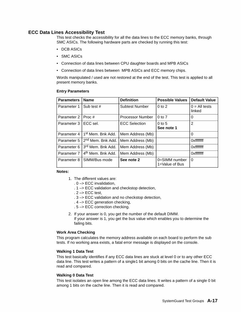
SystemGuard Test Groups A-17
ECC Data Lines Accessibility TestThis test checks the accessibility for all the data lines to the ECC memory banks, throughSMC ASICs. The following hardware parts are checked by running this test:
• DCB ASICs
• SMC ASICs
• Connection of data lines between CPU daughter boards and MPB ASICs
• Connection of data lines between MPB ASICs and ECC memory chips.
Words manipulated / used are not restored at the end of the test. This test is applied to allpresent memory banks.
Entry Parameters
Parameters Name Definition Possible Values Default Value
Parameter 1 Sub test # Subtest Number 0 to 2 0 = All testslinked
Parameter 2 Proc # Processor Number 0 to 7 0
Parameter 3 ECC sel. ECC Selection 0 to 5 See note 1
2
Parameter 4 1st Mem. Bnk Add. Mem Address (Mb) 0
Parameter 5 2nd Mem. Bnk Add. Mem Address (Mb) 0xffffffff
Parameter 6 3rd Mem. Bnk Add. Mem Address (Mb) 0xffffffff
Parameter 7 4th Mem. Bnk Add. Mem Address (Mb) 0xffffffff
Parameter 8 SIMM/Bus mode See note 2 0=SIMM number1=Value of Bus
0
Notes:
1. The different values are:. 0 –> ECC invalidation,. 1 –> ECC validation and checkstop detection,. 2 –> ECC test,. 3 –> ECC validation and no checkstop detection,. 4 –> ECC generation checking,. 5 –> ECC correction checking.
2. If your answer is 0, you get the number of the default DIMM.If your answer is 1, you get the bus value which enables you to determine thefailing bits.
Work Area CheckingThis program calculates the memory address available on each board to perform the subtests. If no working area exists, a fatal error message is displayed on the console.
Walking 1 Data TestThis test basically identifies if any ECC data lines are stuck at level 0 or to any other ECCdata line. This test writes a pattern of a single1 bit among 0 bits on the cache line. Then it isread and compared.
Walking 0 Data TestThis test isolates an open line among the ECC data lines. It writes a pattern of a single 0 bitamong 1 bits on the cache line. Then it is read and compared.
Service GuideA-18
ECC Memory Component TestThis test is identical to the main memory components test but it is applied to the ECCmemory components.
Error Correction Mechanism TestThis test checks the hardware mechanisms enabling the detection of and the correction ofsingle bit errors when working with the main memory. It also detects double errors.
Memory Refresh Mechanism TestThis test is performed by all the processors. It checks the mechanism embedded in the SMCASIC enabling it to refresh the main memory. This test checks the SMC ASIC hardwarepartially. This test contains the following sub-test.
Refresh Mechanism TestIn this test, the memory address is calculated first. Then twocomplementary patterns are written in the work area. Then a readand compare operation is done. If an error is detected, a Memoryread error is displayed. The refresh mechanism is checked in thefollowing manner.
A read operation is done on another location (other than the onepreviously read) until the delay time is over. Then the previouslocation is once again read, to verify the presence of the same data(this is possible, only if the chip is refreshed periodically).
Main Memory full TestThis test performs the most complete test on the main memory, using the Knaizuk-Hartmannalgorithm.
This test is very long (about 20 minutes) when the memory capacity to be checked is large(2GB). So, it is performed only as an extended test or under the OFF line test monitorcontrol.

SystemGuard Test Groups A-19
Interrupt Tests GroupThese tests are performed by the BUMP as well as the processors. They are launched atPower On and under control of Off Line Test Monitor. They collectively check the interruptsystem. The following tests are available under this group.
BUMP To CPU Interrupt TestThis test is performed jointly by the BUMP and the processor. It contains one sub-test whichchecks the capability of the BUMP to generate an interrupt request to one CPU. The errorscan be either detected by the BUMP or by the processor. They are suitably displayed on theconsole. This test also checks the following hardware parts:
1. Processor Interrupt Capability2. Interrupt Management of SSGA3. Control Logic PLD.
CPU To BUMP Interrupt TestThis test is performed jointly by the BUMP and the processor. It contains one sub-test whichchecks the capability of the processor to generate an interrupt request to BUMP. The errorscan be either detected by the BUMP or by the processor. They are suitably displayed on theconsole. This test also checks the following hardware parts:
1. BUMP Interrupt Capability2. Interrupt Management of SSGA3. Control Logic PLD.
UART To CPU Interrupt TestThis test is performed by the processor. It has a sub-test which checks the capability of theSuper-I/O Async line to generate an interrupt request to the CPU. The following hardwareparts are checked by the test:
1. Processor Interrupt Capability2. SSGA Interrupt Management3. PLD Control Logic4. Super-I/O Interrupt Mechanism.
Whenever an error is detected by the processor, an error message giving the details of theerror is displayed.
CPU To CPU Interrupt TestThis test checks the capability for a CPU to interrupt another CPU. The two CPUs of thesame card are used (the capability for a CPU to interrupt a CPU located an another CPUcard is not used in this test).
TOD To BUMP Interrupt TestThis test is launched and performed by the BUMP. It has one sub-test to check the interruptgenerating mechanism of the TOD chip.
This test checks the BUMP and TOD hardware during the process. TOD internal registersare not modified during the test. This test displays error messages during the test if an erroris detected.
Service GuideA-20
CPU MultiProcessor Test GroupThese tests are launched at Power-On and are also available under the control of the OffLine Tests monitor. These tests check the multi-processor mechanisms, atomic instructions,cache coherency, main memory sharing, and multi-resources sharing.
The following tests are available under this group.
Atomic Instructions TestThis test checks the mechanisms enabling the protection of the content of the memory incase of use of some specific instructions, called “atomic instructions”.
Cache Coherency TestThis test is performed by two processors on the same CPU card. It checks the capability of aCPU card to manage all the hardware systems, maintaining the coherency between all thecaches. This test checks the following hardware parts:
1. CPU processors (partially)2. CCA2 ASICs3. CCD ASICs4. L2 cache.
This test is made of 9 sub-tests, which are launched on two processors, Processor 0 andProcessor 1. Processor 1 is often used to verify the operation started by Processor 0. Thesetwo processors concurrently access the same memory area, with various access modesenabled. The following is a brief description of the various sub-tests. Suitable errormessages are generated by each test, whenever an error is detected.
Concurrent Coherent Write Access-Copy BackIn this test, both the processors are enabled in Global Copy Backmode. The snoop mechanism is activated to ensure cachecoherency. Processor 0, writes a half word in memory (actually,data is in Processor 0 cache). Then Processor 1 writes another halfword in memory (actually, data is in Processor 1 cache). WhenProcessor 1 is writing, Processor 0 cache updates memory. WhenProcessor 0 tries to read the full word, Processor 1 cache is erased.
Concurrent Not Coherent Write Access-Copy BackThis test puts both the processors in Local Copy Back Mode. Eachprocessor does a write-read operation.
The global snoop mechanism is not enabled in this test and thecaches are not coherent. So when Processor 0 is reading memory,Processor 1 cache is not erased.
Concurrent Coherent Write Access-DCBST from Line OwnerThis test verifies the DCBST(update memory) instruction from theProcessor 0. Processor 0 is set to Global Write Through mode andcaching is enabled. The odd processor is uncached withoutcoherency.
Concurrent Coherent Write Access-DCBF from Line OwnerIn this test, Processor 0 is enabled for Write through and Memorycoherency parameters. Processor 0 issues a DCBF (Data CacheBlock Flush) instruction. Processor 1 cache is inhibited and memorycoherency is absent.
Concurrent Coherent Write Access-DCBI from Line OwnerThis test verifies the DCBI (Data Cache Block Invalidate)
SystemGuard Test Groups A-21
instruction. This is issued by Processor 0 which is set to GlobalCopy Back mode. Caching is inhibited for Processor 1.
Paradox Detection: DCBST not from Line OwnerHere, Processor 1 is set to Local Copy Back mode. Memorycoherency is enabled for Processor 0. This test verifies theincoherency introduced by the Local Copy Back. Execution ofDCBST by Processor 1 is not verified.
Paradox Detection: DCBF not from Line OwnerThis test enables the Processor 0 for memory coherency. Processor1 is set to Local Copy Back mode. The DCBF instruction is run fromProcessor 1 and verified.
Paradox Detection: DCBI not from Line OwnerIn this test, the DCBI instruction is run by Processor 1 when it isuncached. The even processor is set to Global Loop Back mode.
Paradox Detection: DCBT not from Line OwnerIn this test, Processor 0 is made to verify the result of the DCBT(Data Cache Block Touch) instruction on the Processor 1 cache.
The odd processor cache is inhibited without coherency. Processor0 is set to Global Copy Back mode, with memory coherencyenabled.
DCB Ports Arbitration TestThis test checks the different data flows through the DCB asics.
TLB Mechanism TestThis test is performed by two processors on the same CPU card. It contains one sub-testcalled “TLB Invalidate in Multiprocessor environment Test”. This test checks the TLBmechanism. The following hardware parts are also checked by this test:
1. Processors (partially)2. CCA2 ASICs3. CCD ASICs.
System I/O Sharing TestThis test is performed by all the processors. It contains one sub-test which checks thecapability of all the processors to simultaneously access the same Standard I/O resources.Here, it checks the Flash EPROM and NVRAM. It also checks the following hardware parts:
1. DCBs ASICs2. IONIAN ASICs3. SSGA ASIC.
The test is launched by the BUMP and performed by all the configured processors. TheBUMP manages the test and reports the global test results.
Service GuideA-22
Main Memory Sharing TestThis test is launched by the BUMP and performed by all configured processors. It has asub-test to check the capability of all the processors to access the main memory. Thefollowing hardware parts are checked during the process:
1. DCB ASICs2. IONIAN ASICs3. SSGA ASIC4. SMC ASIC.
BUMP displays the overall test results.
Multi Resource Sharing TestBUMP launches and manages the test results. All configured processors perform this test. Ithas one sub-test, which checks the capability of all the processors to access the followingI/O resources simultaneously:
1. Main Memory2. NVRAM3. Async Lines.
The following hardware parts are checked during the process.
1. DCB ASICs2. IONIAN ASICs3. SSGA ASIC4. SMC ASIC.
Multi Resources Full TestThis test is the hardest test performed by the machine. To be fully efficient, it must be:
• launched on three processors at least (one of them is used as a de-synchronizeprocessor).
• performed during thirty seconds at least. Its main characteristic is to perform randomaccesses into main memory, with a very high implication of L1 and L2 caches.

Modifying SystemGuard Parameters B-1
Appendix B. Modifying SystemGuard Parameters
Many SystemGuard parameters can be modified in several ways. Some can be modifiedusing the SystemGuard Stand-By menu, others using the SystemGuard Maintenance menu,and others using the AIX diag or mpcfg commands or Diagnostic Service Aids. When youwant to modify SystemGuard parameters, the method to use depends on the machine bootphase (stand-by, init, run-time). This chapter explains how to change some of the moreimportant flags and parameters depending on the current machine state. For a complete listof default values for flags and parameters, see the table in “Default Parameter Values” onpage B-1.
The Mode Switch must be in the Service position to use the SystemGuard menus. If themachine is in the stand-by phase, you must press the Enter key to get the SystemGuardprompt, and then enter the keyword sbb to display the stand-by menu. If you enter thepower-on keyword (power ), or if you turn the power on manually, the machine enters the initphase and displays the maintenance menu if the AutoService IPL flag is disabled. TheAutoService IPL flag is normally enabled. If the AutoService IPL flag is enabled, then theflag must be disabled before the maintenance menu can be entered. The AutoService IPLflag can be disabled when the system is in stand-by phase by pressing the Enter key andthen entering the keyword sbb to display the Stand-by Menu. Select the Set Flags option.The AutoService IPL flag can now be disabled. The AutoService IPL flag can also bedisabled using the Service Aids.
When changing parameters under the AIX operating system, the Diagnostic Service Aidsare recommended because its menu interface is better suited to interactive use. The mpcfgcommand requires the use of command line flags and is better suited for shell scripts. Thecommand requires root authority. Also, the Service Aids require root authority if entered withthe diag command. They display or change flag values using 0 (zero) for disabled and 1(one) for enabled. The explanations that follow refer to the Diagnostic Service Aids.
Default Parameter ValuesThe flags, parameters and keywords used by SystemGuard programs are stored innon-volatile memory (NVRAM). They are given default values before leaving the factory, asshown in the table on the following page.
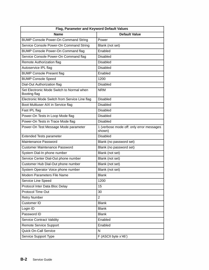
B-2 Service Guide
Flag, Parameter and Keyword Default Values
Name Default Value
BUMP Console Power-On Command String Power
Service Console Power-On Command String Blank (not set)
BUMP Console Power-On Command flag Enabled
Service Console Power-On Command flag Disabled
Remote Authorization flag Disabled
Autoservice IPL flag Disabled
BUMP Console Present flag Enabled
BUMP Console Speed 1200
Dial-Out Authorization flag Disabled
Set Electronic Mode Switch to Normal whenBooting flag
NRM
Electronic Mode Switch from Service Line flag Disabled
Boot Multiuser AIX in Service flag Disabled
Fast IPL flag Disabled
Power-On Tests in Loop Mode flag Disabled
Power-On Tests in Trace Mode flag Disabled
Power-On Test Message Mode parameter 1 (verbose mode off: only error messagesshown)
Extended Tests parameter Disabled
Maintenance Password Blank (no password set)
Customer Maintenance Password Blank (no password set)
System Dial-In phone number Blank (not set)
Service Center Dial-Out phone number Blank (not set)
Customer Hub Dial-Out phone number Blank (not set)
System Operator Voice phone number Blank (not set)
Modem Parameters File Name Blank
Service Line Speed 1200
Protocol Inter Data Bloc Delay 15
Protocol Time Out 30
Retry Number 2
Customer ID Blank
Login ID Blank
Password ID Blank
Service Contract Validity Enabled
Remote Service Support Enabled
Quick On-Call Service N
Service Support Type F (ASCII byte x’46’)
Modifying SystemGuard Parameters B-3
Changing Flags and Parameters Under AIX Service AidsThe Service Aids are recommended to change the flags. The Service Aids can be enteredusing the diag command or by booting diagnostics in service mode. They display or changeflag values using 0 (zero) for disabled and 1 (one) for enabled. The explanations that followrefer to the Service Aids.
Modifying Diagnostic FlagsUse this procedure to modify diagnostic flags such as the Remote Authorization flag or theAutoservice IPL flag. Starting from the Service Aids Selection menu:
1. Select the BUMP Service Aids option.
2. Select the Display or Change Flags and Configuration option.
3. Select the Change Diagnostic Flags option to display a menu of diagnostic flags.
4. Select a flag and enter its new value.
Modifying the Modem and Site ConfigurationUse this procedure to modify modem and site configuration parameters such as the modemconfiguration file name or the service line speed. Starting from the Service Aids Selectionmenu:
1. Select the BUMP Service Aids option.
2. Select the Display or Change Flags and Configuration option.
3. Select the Change Modem and Site Configuration option to display a menu.
4. Select a flag and enter its new value.
Saving or Restoring Flags and Configuration InformationUse this procedure to save or to restore the configuration using a file. Starting from theService Aids Selection menu:
1. Select the BUMP Service Aids option.
2. Select the Save or Restore Flags and Configuration option.
3. Select either the Save or the Restore option.
Modifying the Remote Authorization FlagThis flag can be changed under SystemGuard using the stand-by or maintenance menus, orunder AIX using the diag command.
SystemGuard Stand-by MenuStarting from the main stand-by menu:
1. Enter 1 (one) to set flags.
2. Enter 0 (zero) to change the Remote Authorization flag.

B-4 Service Guide
SystemGuard Maintenance MenuStarting from the main maintenance menu:
• Enter 2 to enable the flag.
OR
• Enter 3 to disable the flag.
AIX Diag CommandStarting from the Service Aids Selection menu:
1. Select the BUMP Service Aids option.
2. Select the Display or Change Flags and Configuration option.
3. Select the Change Diagnostic Flags option.
4. Select the Remote Authorization option.
5. Supply a new flag value (0 or 1).
Modifying the Dial-Out Authorization FlagThis flag can be changed under SystemGuard using the maintenance menu, or under AIXusing the diag command.
SystemGuard Maintenance MenuStarting from the main maintenance menu:
1. Enter 8 to set parameters.
2. Enter 4 for miscellaneous parameters.
3. Enter 2 to change the Dial-Out Authorization flag.
AIX Diag CommandStarting from the Service Aids Selection menu:
1. Select the BUMP Service Aids option.
2. Select the Display or Change Flags and Configuration option.
3. Select the Change Diagnostic Flags option.
4. Select the Dial-Out Authorization option.
5. Supply a new flag value (0 or 1).
Modifying SystemGuard Parameters B-5
Modifying Dial-In Phone NumbersThese parameters can be changed under SystemGuard using the maintenance menu, orunder AIX using the diag command.
SystemGuard Maintenance MenuStarting from the main maintenance menu:
1. Enter 8 to set parameters.
2. Enter 3 for phone numbers.
3. Enter 4 for the dial-in phone number.
4. Supply a new phone number.
AIX Diag CommandStarting from the Service Aids Selection menu:
1. Select the BUMP Service Aids option.
2. Select the Display or Change Flags and Configuration option.
3. Select the Change Remote Support Phone Numbers option.
4. Select the System Dial-In option.
5. Supply a new phone number.
Modifying Dial-Out Phone NumbersThese parameters can be changed under SystemGuard using the maintenance menu, orunder AIX using the diag command.
SystemGuard Maintenance MenuStarting from the main maintenance menu:
1. Enter 8 to set parameters.
2. Enter 3 for phone numbers.
3. Select the dial-out phone number to modify (service center or customer hub).
4. Supply a new phone number.
AIX Diag CommandStarting from the Service Aids Selection menu:
1. Select the BUMP Service Aids option.
2. Select the Display or Change Flags and Configuration option.
3. Select the Change Remote Support Phone Numbers option.
4. Select the Service Center Dial-Out or Customer Hub Dial-Out option.
5. Supply a new phone number.
B-6 Service Guide
Modifying the Electronic Mode Switch from Service Line FlagThis flag can be changed under SystemGuard using the maintenance menu, or under AIXusing the diag command.
SystemGuard Maintenance MenuStarting from the main maintenance menu:
1. Enter 8 to set parameters.
2. Enter 4 for miscellaneous parameters.
3. Enter 9 to change the Electronic Mode Switch from Service Line flag.
AIX Diag CommandStarting from the Service Aids Selection menu:
1. Select the BUMP Service Aids option.
2. Select the Display or Change Flags and Configuration option.
3. Select the Change Diagnostic Flags option.
4. Select the Electronic Mode Switch from Service Line option.
5. Supply a new flag value (0 or 1).

Modifying SystemGuard Parameters B-7
Reloading the Flash EEPROMFollow this procedure to load a new version of SystemGuard into the flash EEPROM. Onlysystem administrators should perform this procedure.
PrerequisitesTo install a new version of the EEPROM firmware, you need either a firmware diskettecontaining a binary firmware image, or a file containing the firmware. The operating systemand some operating system updates come with firmware diskettes. Using a diskette isquicker than using a file.
You can also update the firmware using a file containing a new firmware version. Althoughthis method takes longer because you have to reboot the system, it is useful in certaincases. For example, you may not have a diskette, or you may electronically receive a morerecent firmware version from customer service personnel.
Updating the Flash EEPROM (using a firmware diskette)If the system is not yet powered on, simply insert the firmware diskette in the drive, place theMode Switch in the Service position, and then power on the system. The firmware diskette isidentified by a special header which distinguishes it from diskettes containing other data.The existing firmware recognizes the special header and automatically loads the newfirmware version.
If AIX is already up and running (the run-time phase), reloading the firmware requires moresteps, because you first have to shut down the system, then reboot the machine asdescribed in the preceding paragraph.
Updating the Flash EEPROM (using a file)An administrator with root authority can use the AIX diag command to update the EEPROMfirmware using a file. Because this procedure reboots the machine after the update, the rootuser who performs this procedure should be the only logged user. If the system is not yetpowered on, power on the system, and log in as the root user without letting other users login. Then follow the steps to use when the system is up and running.
If AIX is already up and running (the run-time phase), perform the following steps:
1. Make sure that no other users are logged in to the system (log them out if necessary).
2. Make sure that you have root authority (use the su command if necessary).
3. Enter the diag command.
4. Select Service Aids.
5. Select the BUMP Service Aids option.
6. Select the Flash Eprom Download option.
7. Enter the full path name for the file containing the new flash EEPROM.
8. The system is automatically rebooted

B-8 Service Guide
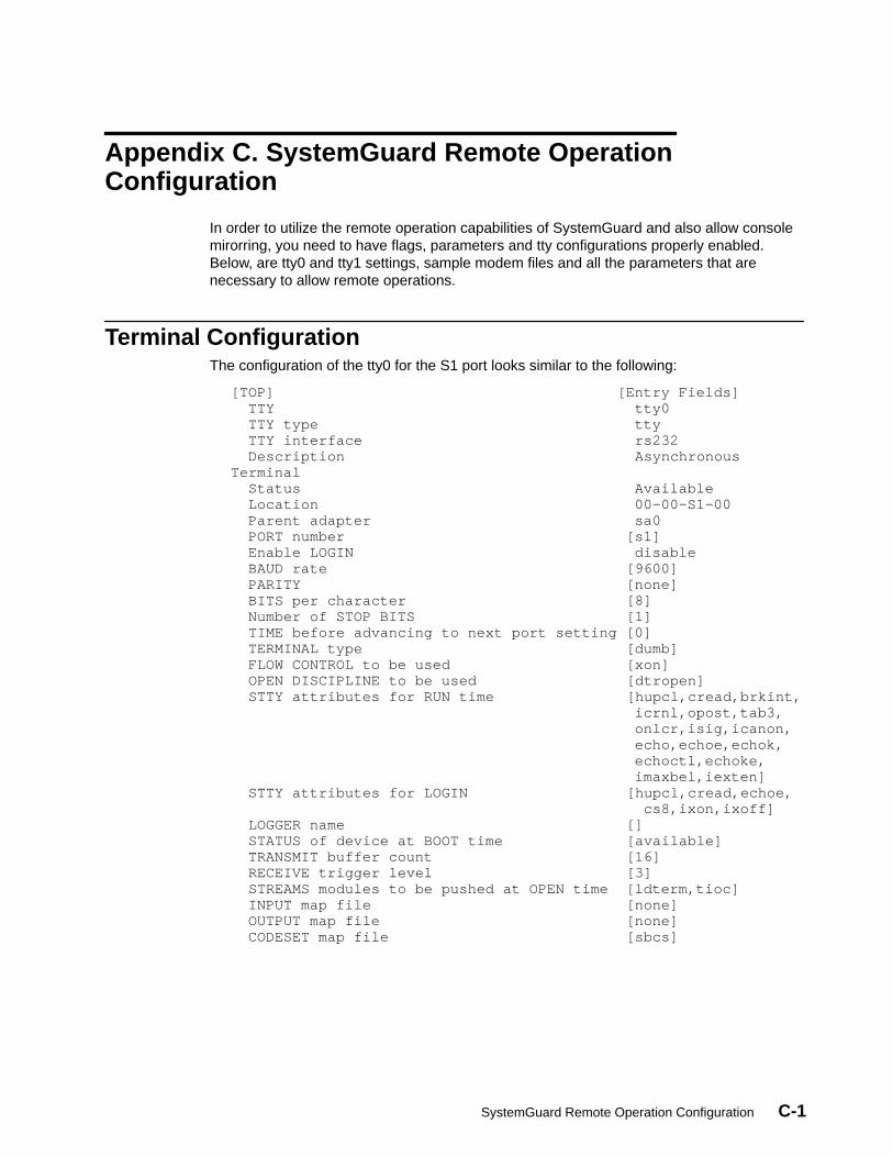
SystemGuard Remote Operation Configuration C-1
Appendix C. SystemGuard Remote OperationConfiguration
In order to utilize the remote operation capabilities of SystemGuard and also allow consolemirorring, you need to have flags, parameters and tty configurations properly enabled.Below, are tty0 and tty1 settings, sample modem files and all the parameters that arenecessary to allow remote operations.
Terminal ConfigurationThe configuration of the tty0 for the S1 port looks similar to the following:
[TOP] [Entry Fields] TTY tty0 TTY type tty TTY interface rs232 Description AsynchronousTerminal Status Available Location 00–00–S1–00 Parent adapter sa0 PORT number [s1] Enable LOGIN disable BAUD rate [9600] PARITY [none] BITS per character [8] Number of STOP BITS [1] TIME before advancing to next port setting [0] TERMINAL type [dumb] FLOW CONTROL to be used [xon] OPEN DISCIPLINE to be used [dtropen] STTY attributes for RUN time [hupcl,cread,brkint, icrnl,opost,tab3, onlcr,isig,icanon, echo,echoe,echok, echoctl,echoke, imaxbel,iexten] STTY attributes for LOGIN [hupcl,cread,echoe, cs8,ixon,ixoff] LOGGER name [] STATUS of device at BOOT time [available] TRANSMIT buffer count [16] RECEIVE trigger level [3] STREAMS modules to be pushed at OPEN time [ldterm,tioc] INPUT map file [none] OUTPUT map file [none] CODESET map file [sbcs]

C-2 Service Guide
The configuration of the tty1 for the S2 port looks similar to the following:
[TOP] [Entry Fields] TTY tty1 TTY type tty TTY interface rs232 Description AsynchronousTerminal Status Available Location 00–00–S2–00 Parent adapter sa1 PORT number [s2] Enable LOGIN disable BAUD rate [9600] PARITY [none] BITS per character [8] Number of STOP BITS [1] TIME before advancing to next port setting [0] TERMINAL type [dumb] FLOW CONTROL to be used [rts] OPEN DISCIPLINE to be used [dtropen] STTY attributes for RUN time [hupcl,cread,brkint, icrnl,opost,tab3, onlcr,isig,icanon, echo,echoe,echok, echoctl,echoke, imaxbel,iexten] STTY attributes for LOGIN[hupcl,cread,echoe,cs8, ixon,ixoff] LOGGER name [] STATUS of device at BOOT time [available] TRANSMIT buffer count [16] RECEIVE trigger level [3] STREAMS modules to be pushed at OPEN time [ldterm,tioc] INPUT map file [none] OUTPUT map file [none] CODESET map file [sbcs]
Flags and Parameters SettingsThese are the minimum SystemGuard parameters/flags settings required for remotesupport. These parameters can be displayed and changed through AIX with the mpcfgcommand.
• Modem configuration:
mpcfg –dm Index Name Value 1 Modem Parameters File Name /usr/share/modems/78512 Service Line Speed 96003 Protocol Inter Data Block Delay 54 Protocol Time Out 605 Retry Number 26 Customer ID7 Login ID8 Password ID
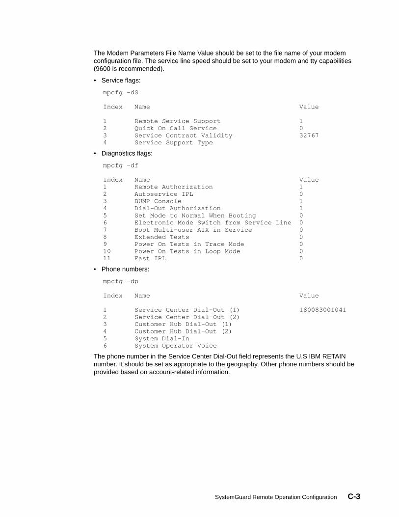
SystemGuard Remote Operation Configuration C-3
The Modem Parameters File Name Value should be set to the file name of your modemconfiguration file. The service line speed should be set to your modem and tty capabilities(9600 is recommended).
• Service flags:
mpcfg –dS Index Name Value 1 Remote Service Support 12 Quick On Call Service 03 Service Contract Validity 327674 Service Support Type
• Diagnostics flags:
mpcfg –df Index Name Value1 Remote Authorization 12 Autoservice IPL 03 BUMP Console 14 Dial–Out Authorization 15 Set Mode to Normal When Booting 06 Electronic Mode Switch from Service Line 07 Boot Multi–user AIX in Service 08 Extended Tests 09 Power On Tests in Trace Mode 010 Power On Tests in Loop Mode 011 Fast IPL 0
• Phone numbers:
mpcfg –dp Index Name Value 1 Service Center Dial–Out (1) 1800830010412 Service Center Dial–Out (2)3 Customer Hub Dial–Out (1)4 Customer Hub Dial–Out (2)5 System Dial–In6 System Operator Voice
The phone number in the Service Center Dial-Out field represents the U.S IBM RETAINnumber. It should be set as appropriate to the geography. Other phone numbers should beprovided based on account-related information.
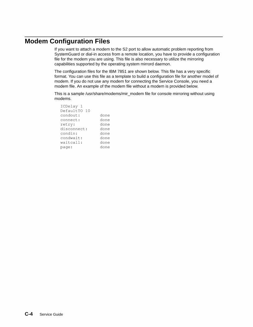
C-4 Service Guide
Modem Configuration FilesIf you want to attach a modem to the S2 port to allow automatic problem reporting fromSystemGuard or dial-in access from a remote location, you have to provide a configurationfile for the modem you are using. This file is also necessary to utilize the mirroringcapabilities supported by the operating system mirrord daemon.
The configuration files for the IBM 7851 are shown below. This file has a very specificformat. You can use this file as a template to build a configuration file for another model ofmodem. If you do not use any modem for connecting the Service Console, you need amodem file. An example of the modem file without a modem is provided below.
This is a sample /usr/share/modems/mir_modem file for console mirroring without usingmodems.
ICDelay 1DefaultTO 10condout: doneconnect: doneretry: donedisconnect: donecondin: donecondwait: donewaitcall: donepage: done
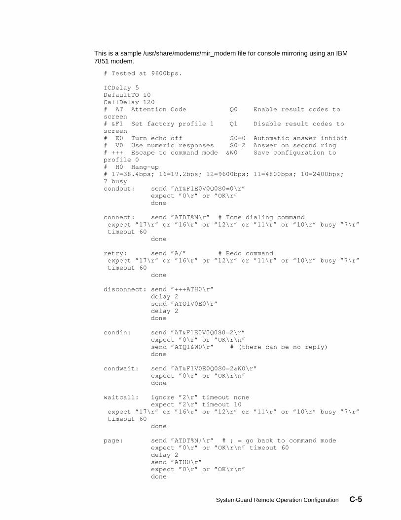
SystemGuard Remote Operation Configuration C-5
This is a sample /usr/share/modems/mir_modem file for console mirroring using an IBM7851 modem.
# Tested at 9600bps. ICDelay 5DefaultTO 10CallDelay 120# AT Attention Code Q0 Enable result codes toscreen# &F1 Set factory profile 1 Q1 Disable result codes toscreen# E0 Turn echo off S0=0 Automatic answer inhibit# V0 Use numeric responses S0=2 Answer on second ring# +++ Escape to command mode &W0 Save configuration toprofile 0# H0 Hang–up# 17=38.4bps; 16=19.2bps; 12=9600bps; 11=4800bps; 10=2400bps;7=busycondout: send ”AT&F1E0V0Q0S0=0\r” expect ”0\r” or ”OK\r”
done connect: send ”ATDT%N\r” # Tone dialing command expect ”17\r” or ”16\r” or ”12\r” or ”11\r” or ”10\r” busy ”7\r” timeout 60 done retry: send ”A/” # Redo command expect ”17\r” or ”16\r” or ”12\r” or ”11\r” or ”10\r” busy ”7\r” timeout 60 done disconnect: send ”+++ATH0\r” delay 2 send ”ATQ1V0E0\r” delay 2
done condin: send ”AT&F1E0V0Q0S0=2\r” expect ”0\r” or ”OK\r\n” send ”ATQ1&W0\r” # (there can be no reply)
done condwait: send ”AT&F1V0E0Q0S0=2&W0\r” expect ”0\r” or ”OK\r\n” done waitcall: ignore ”2\r” timeout none expect ”2\r” timeout 10 expect ”17\r” or ”16\r” or ”12\r” or ”11\r” or ”10\r” busy ”7\r” timeout 60 done page: send ”ATDT%N;\r” # ; = go back to command mode expect ”0\r” or ”OK\r\n” timeout 60 delay 2 send ”ATH0\r” expect ”0\r” or ”OK\r\n” done

C-6 Service Guide
Initializing a ModemOnce flags, parameters and configurations have been enabled, the modem can be initializedto accept incoming calls. This can be done in the following manner:
• Place the System Key to Normal.
• Issue a ps –ef|grep mirrord command.
• Obtain mirrord process ID.
• Issue a kill –9 <mirrord pid> .
• Issue /usr/sbin/mirrord modemfilename .
• Place the System Key into the Service position.
This initiates the mirrord process. The disconnect and condin parameters are read from theappropriate modem file, and the modem is initialized for dial-in activity. After the mirrorddaemon is activated, the System Key should be placed in the Normal position.
Testing Dial-OutDial-out or automatic problem reporting can be tested from the SystemGuard MaintenanceMenu using the Offline Test for Dial-out. Successful connection and transmission of dataresults in an OK completion.
During the test, the modem configuration file is read, the modem initialized properly, anddata transmitted. Comparing the modem configuration file to line activity shows disconnect,condout, connect, transmit of data, disconnect and condin. Thus the modem is initialized fordial-out, data is transmitted, and the modem is initialized to allow dial-in.

Off Line Diagnostic Error Codes D-1
Appendix D. Off Line Diagnostic Error Codes
Note: The Failure Percent value is calculated on a system model base. As some FailingFunction Codes are system model specific but are associated the the same ErrorNumber, it may happen that the sum of the Failure Percent values in one single boxexceeds 100.
ErrorNumber Source
FailingFunction
Codes
FailurePercent
(%)
Description
401-000 K C59 100 Description S1 asynchronous line internal registers error.Action: Use MAP 0210.
401-001 K C59 100 Description: S1 asynchronous line buffer exchange error.Action: Use MAP 0210.
401-002 K C59 100 Description: S1 asynchronous line junction signal error (initialtest).Action: Use MAP 0210.
401-003 K C59 100 Description: S1 asynchronous line junction signal error (DTR toDSR link).Action: Use MAP 0210.
401-004 K C59 100 Description: S1 asynchronous line junction signal error (RTS toCTS link).Action: Use MAP 0210.
401-005 K C59 100 Description: S1 asynchronous line junction signal error (OUT2 toDCD link).Action: Use MAP 0210.
401-006 K C59 100 Description: S1 asynchronous line junction signal error (OUT1 toRI link).Action: Use MAP 0210.
401-007 K C59 100 Description: S1 asynchronous line buffer exchange error. Externalloop-back mode.Action: Use MAP 0210.
401-008 K C59 100 Description: S1 asynchronous line junction signal error (RTS toCTS link). External loop-back mode.Action: Use MAP 0210.
401-009 K C59 100 Description: S1 asynchronous line junction signal error (DTR toDSR link). External loop-back mode.Action: Use MAP 0210.
401-010 K C59 100 Description: S1 asynchronous line speed error. Externalloop-back mode.Action: Use MAP 0210.
401-020 K C59 100 Description: S2 asynchronous line internal registers error.Action: Use MAP 0210.
401-021 K C59 100 Description: S2 asynchronous line buffer exchange error.Action: Use MAP 0210.
401-022 K C59 100 Description: S2 asynchronous line junction signal error (initialtest).Action: Use MAP 0210.
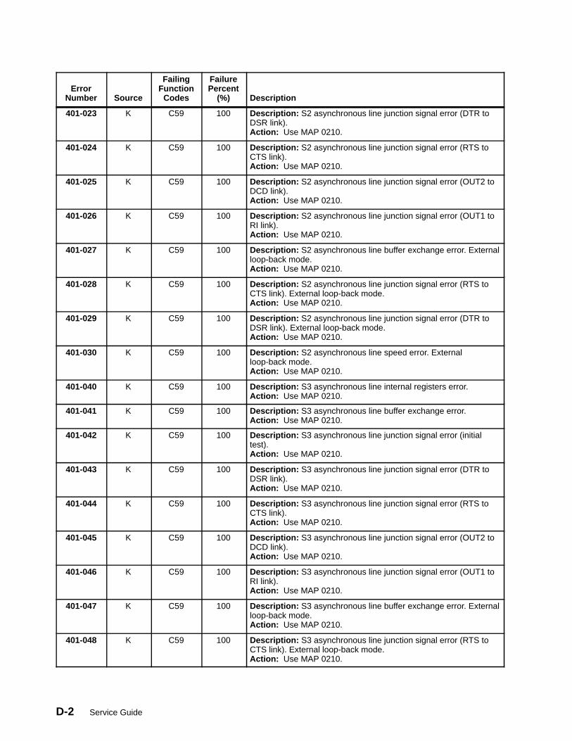
Service GuideD-2
ErrorNumber Source
FailingFunction
Codes
FailurePercent
(%)
Description
401-023 K C59 100 Description: S2 asynchronous line junction signal error (DTR toDSR link).Action: Use MAP 0210.
401-024 K C59 100 Description: S2 asynchronous line junction signal error (RTS toCTS link).Action: Use MAP 0210.
401-025 K C59 100 Description: S2 asynchronous line junction signal error (OUT2 toDCD link).Action: Use MAP 0210.
401-026 K C59 100 Description: S2 asynchronous line junction signal error (OUT1 toRI link).Action: Use MAP 0210.
401-027 K C59 100 Description: S2 asynchronous line buffer exchange error. Externalloop-back mode.Action: Use MAP 0210.
401-028 K C59 100 Description: S2 asynchronous line junction signal error (RTS toCTS link). External loop-back mode.Action: Use MAP 0210.
401-029 K C59 100 Description: S2 asynchronous line junction signal error (DTR toDSR link). External loop-back mode.Action: Use MAP 0210.
401-030 K C59 100 Description: S2 asynchronous line speed error. Externalloop-back mode.Action: Use MAP 0210.
401-040 K C59 100 Description: S3 asynchronous line internal registers error.Action: Use MAP 0210.
401-041 K C59 100 Description: S3 asynchronous line buffer exchange error.Action: Use MAP 0210.
401-042 K C59 100 Description: S3 asynchronous line junction signal error (initialtest).Action: Use MAP 0210.
401-043 K C59 100 Description: S3 asynchronous line junction signal error (DTR toDSR link).Action: Use MAP 0210.
401-044 K C59 100 Description: S3 asynchronous line junction signal error (RTS toCTS link).Action: Use MAP 0210.
401-045 K C59 100 Description: S3 asynchronous line junction signal error (OUT2 toDCD link).Action: Use MAP 0210.
401-046 K C59 100 Description: S3 asynchronous line junction signal error (OUT1 toRI link).Action: Use MAP 0210.
401-047 K C59 100 Description: S3 asynchronous line buffer exchange error. Externalloop-back mode.Action: Use MAP 0210.
401-048 K C59 100 Description: S3 asynchronous line junction signal error (RTS toCTS link). External loop-back mode.Action: Use MAP 0210.

Off Line Diagnostic Error Codes D-3
ErrorNumber Source
FailingFunction
Codes
FailurePercent
(%)
Description
401-049 K C59 100 Description: S3 asynchronous line junction signal error (DTR toDSR link). External loop-back mode.Action: Use MAP 0210.
401-050 K C59 100 Description: S3 asynchronous line speed error. Externalloop-back mode.Action: Use MAP 0210.
401-060 K C59 100 Description: Flash EPROM standard area checksum error.Action: Use MAP 0210.
401-061 K C59 100 Description: Flash EPROM IPL area checksum error.Action: Use MAP 0210.
401-070 K C59 100 Description: NVRAM error 1.Action: Use MAP 0210.
401-071 K C59 100 Description: NVRAM error 2.Action: Use MAP 0210.
401-080 K C59 100 Description: EPROM standard area checksum error.Action: Use MAP 0210.
401-081 K C59 100 Description: EPROM IPL area checksum error.Action: Use MAP 0210.
401-090 K C59 100 Description: TOD MSR register error.Action: Use MAP 0210.
401-091 K C59 100 Description: TOD internal RAM error.Action: Use MAP 0210.
401-092 K C59 100 Description: TOD wake-up mechanism error.Action: Use MAP 0210.
401-100 K C59 100 Description: Floppy disk controller DOR register error.Action: Use MAP 0210.
401-100 K C59 100 Description: Floppy disk controller DOR register error.Action: Use MAP 0210.
401-110 K C59 100 Description: BPP address register error.Action: Use MAP 0210.
401-111 K C59 100 Description: BPP DTR register error.Action: Use MAP 0210.
401-112 K C59 100 Description: BPP CTR register error.Action: Use MAP 0210.
401-120 K C59 100 Description: Miscellaneous PGCR register error.Action: Use MAP 0210.
401-121 K C59 100 Description: Miscellaneous DTR register error.Action: Use MAP 0210.
401-130 K C59C61C63
502525
Description: CPU accessibility.Checkstop error.Action: Use MAP 0210.
401-131 K C59C61C63
502525
Description: CPU accessibility.Single error.Action: Use MAP 0210.
401-132 K C59C61C63
502525
Description: CPU accessibility.CPU not started.Action: Use MAP 0210.
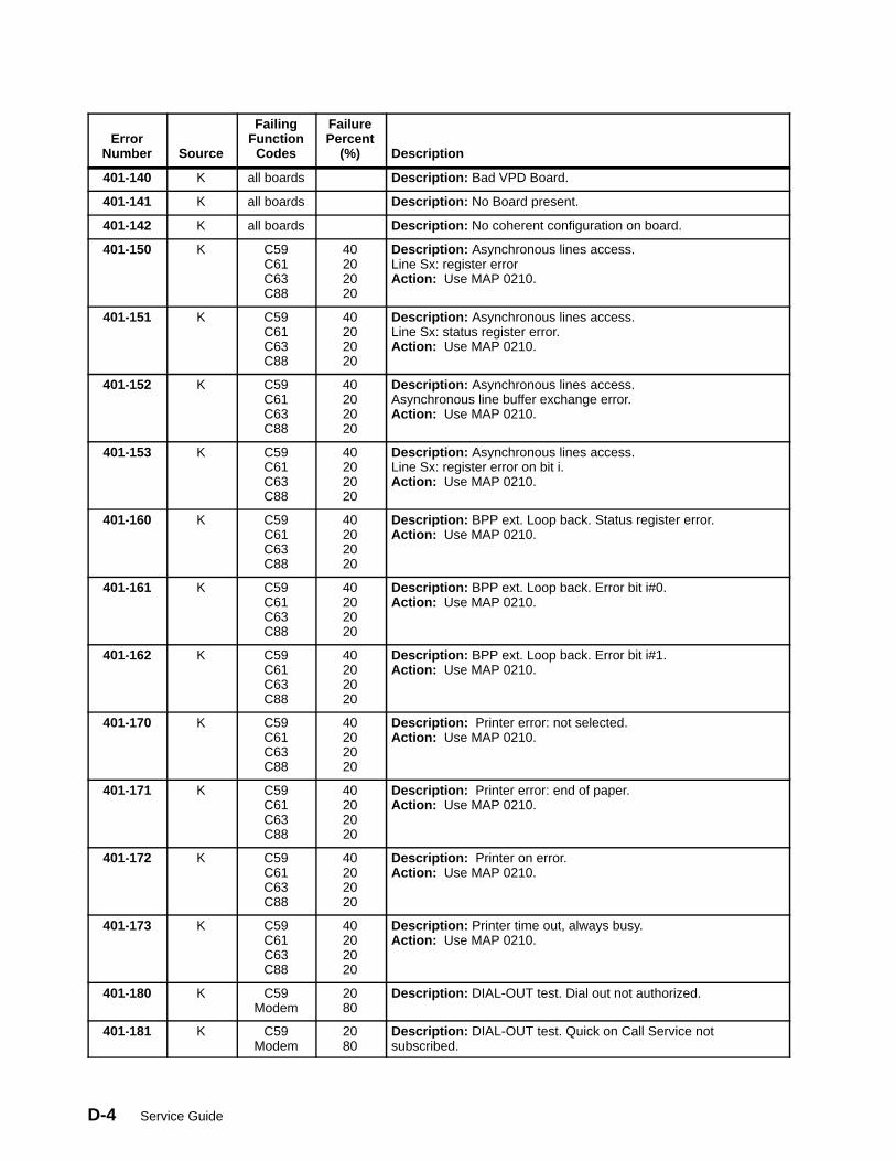
Service GuideD-4
ErrorNumber Source
FailingFunction
Codes
FailurePercent
(%)
Description
401-140 K all boards Description: Bad VPD Board.
401-141 K all boards Description: No Board present.
401-142 K all boards Description: No coherent configuration on board.
401-150 K C59C61C63C88
40202020
Description: Asynchronous lines access.Line Sx: register errorAction: Use MAP 0210.
401-151 K C59C61C63C88
40202020
Description: Asynchronous lines access.Line Sx: status register error.Action: Use MAP 0210.
401-152 K C59C61C63C88
40202020
Description: Asynchronous lines access.Asynchronous line buffer exchange error.Action: Use MAP 0210.
401-153 K C59C61C63C88
40202020
Description: Asynchronous lines access.Line Sx: register error on bit i.Action: Use MAP 0210.
401-160 K C59C61C63C88
40202020
Description: BPP ext. Loop back. Status register error.Action: Use MAP 0210.
401-161 K C59C61C63C88
40202020
Description: BPP ext. Loop back. Error bit i#0.Action: Use MAP 0210.
401-162 K C59C61C63C88
40202020
Description: BPP ext. Loop back. Error bit i#1.Action: Use MAP 0210.
401-170 K C59C61C63C88
40202020
Description: Printer error: not selected.Action: Use MAP 0210.
401-171 K C59C61C63C88
40202020
Description: Printer error: end of paper.Action: Use MAP 0210.
401-172 K C59C61C63C88
40202020
Description: Printer on error.Action: Use MAP 0210.
401-173 K C59C61C63C88
40202020
Description: Printer time out, always busy.Action: Use MAP 0210.
401-180 K C59Modem
2080
Description: DIAL-OUT test. Dial out not authorized.
401-181 K C59Modem
2080
Description: DIAL-OUT test. Quick on Call Service notsubscribed.
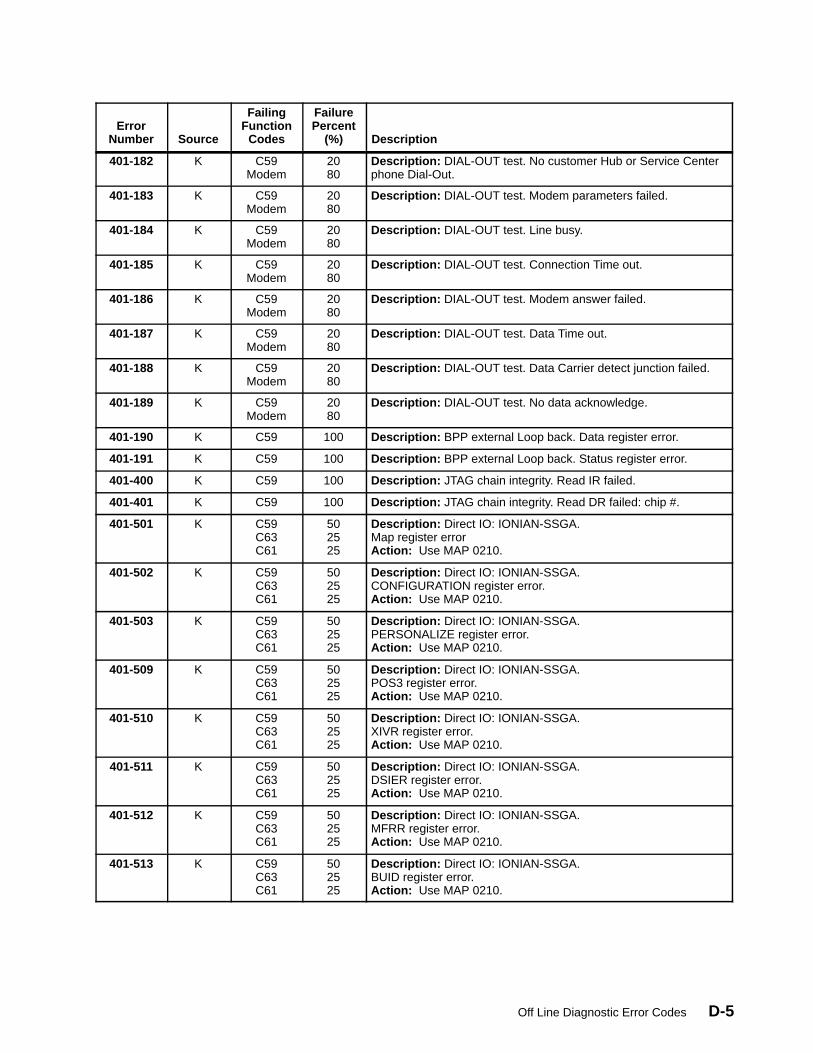
Off Line Diagnostic Error Codes D-5
ErrorNumber
Description
FailurePercent
(%)
FailingFunction
CodesSource
401-182 K C59Modem
2080
Description: DIAL-OUT test. No customer Hub or Service Centerphone Dial-Out.
401-183 K C59Modem
2080
Description: DIAL-OUT test. Modem parameters failed.
401-184 K C59Modem
2080
Description: DIAL-OUT test. Line busy.
401-185 K C59Modem
2080
Description: DIAL-OUT test. Connection Time out.
401-186 K C59Modem
2080
Description: DIAL-OUT test. Modem answer failed.
401-187 K C59Modem
2080
Description: DIAL-OUT test. Data Time out.
401-188 K C59Modem
2080
Description: DIAL-OUT test. Data Carrier detect junction failed.
401-189 K C59Modem
2080
Description: DIAL-OUT test. No data acknowledge.
401-190 K C59 100 Description: BPP external Loop back. Data register error.
401-191 K C59 100 Description: BPP external Loop back. Status register error.
401-400 K C59 100 Description: JTAG chain integrity. Read IR failed.
401-401 K C59 100 Description: JTAG chain integrity. Read DR failed: chip #.
401-501 K C59C63C61
502525
Description: Direct IO: IONIAN-SSGA.Map register errorAction: Use MAP 0210.
401-502 K C59C63C61
502525
Description: Direct IO: IONIAN-SSGA.CONFIGURATION register error.Action: Use MAP 0210.
401-503 K C59C63C61
502525
Description: Direct IO: IONIAN-SSGA.PERSONALIZE register error.Action: Use MAP 0210.
401-509 K C59C63C61
502525
Description: Direct IO: IONIAN-SSGA.POS3 register error.Action: Use MAP 0210.
401-510 K C59C63C61
502525
Description: Direct IO: IONIAN-SSGA.XIVR register error.Action: Use MAP 0210.
401-511 K C59C63C61
502525
Description: Direct IO: IONIAN-SSGA.DSIER register error.Action: Use MAP 0210.
401-512 K C59C63C61
502525
Description: Direct IO: IONIAN-SSGA.MFRR register error.Action: Use MAP 0210.
401-513 K C59C63C61
502525
Description: Direct IO: IONIAN-SSGA.BUID register error.Action: Use MAP 0210.
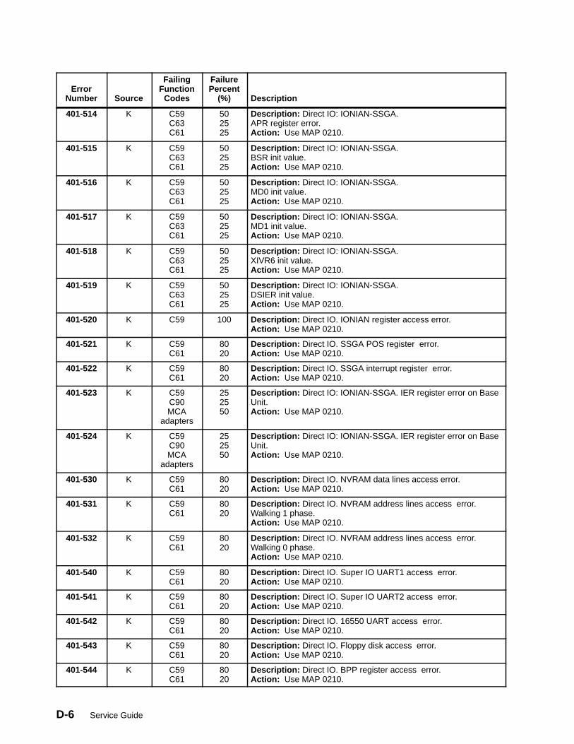
Service GuideD-6
ErrorNumber Source
FailingFunction
Codes
FailurePercent
(%)
Description
401-514 K C59C63C61
502525
Description: Direct IO: IONIAN-SSGA.APR register error.Action: Use MAP 0210.
401-515 K C59C63C61
502525
Description: Direct IO: IONIAN-SSGA.BSR init value.Action: Use MAP 0210.
401-516 K C59C63C61
502525
Description: Direct IO: IONIAN-SSGA.MD0 init value.Action: Use MAP 0210.
401-517 K C59C63C61
502525
Description: Direct IO: IONIAN-SSGA.MD1 init value.Action: Use MAP 0210.
401-518 K C59C63C61
502525
Description: Direct IO: IONIAN-SSGA.XIVR6 init value.Action: Use MAP 0210.
401-519 K C59C63C61
502525
Description: Direct IO: IONIAN-SSGA.DSIER init value.Action: Use MAP 0210.
401-520 K C59 100 Description: Direct IO. IONIAN register access error.Action: Use MAP 0210.
401-521 K C59C61
8020
Description: Direct IO. SSGA POS register error.Action: Use MAP 0210.
401-522 K C59C61
8020
Description: Direct IO. SSGA interrupt register error.Action: Use MAP 0210.
401-523 K C59C90MCA
adapters
252550
Description: Direct IO: IONIAN-SSGA. IER register error on BaseUnit.Action: Use MAP 0210.
401-524 K C59C90MCA
adapters
252550
Description: Direct IO: IONIAN-SSGA. IER register error on BaseUnit.Action: Use MAP 0210.
401-530 K C59C61
8020
Description: Direct IO. NVRAM data lines access error.Action: Use MAP 0210.
401-531 K C59C61
8020
Description: Direct IO. NVRAM address lines access error.Walking 1 phase.Action: Use MAP 0210.
401-532 K C59C61
8020
Description: Direct IO. NVRAM address lines access error.Walking 0 phase.Action: Use MAP 0210.
401-540 K C59C61
8020
Description: Direct IO. Super IO UART1 access error.Action: Use MAP 0210.
401-541 K C59C61
8020
Description: Direct IO. Super IO UART2 access error.Action: Use MAP 0210.
401-542 K C59C61
8020
Description: Direct IO. 16550 UART access error.Action: Use MAP 0210.
401-543 K C59C61
8020
Description: Direct IO. Floppy disk access error.Action: Use MAP 0210.
401-544 K C59C61
8020
Description: Direct IO. BPP register access error.Action: Use MAP 0210.

Off Line Diagnostic Error Codes D-7
ErrorNumber
Description
FailurePercent
(%)
FailingFunction
CodesSource
401-550 K C59C61C90C91
8020
Description: Direct IO. Flash Eprom access error.Action: Use MAP 0210.
401-560 K C59C61
8020
Description: Direct IO. Eprom access error.Action: Use MAP 0210.
401-570 K C59C61
8020
Description: Direct IO. TOD imbedded RAM access error.Action: Use MAP 0210.
401-571 K C59C61
8020
Description: Direct IO. TOD registers access error.Action: Use MAP 0210.
401-58A K C59C90MCA
adapters
252550
Description: Direct IO: IONIAN2. IER register error on ExpansionUnit.Action: Use MAP 0210.
401-58B K C59C90MCA
adapters
252550
Description: Direct IO: IONIAN2. IER register error on ExpansionUnit.Action: Use MAP 0210.
401-580 K C59C63C61
502525
Description: Direct IO: IONIAN2.TCE register error.Action: Use MAP 0210.
401-581 K C59C63C61
502525
Description: Direct IO: IONIAN2.MAP register error.Action: Use MAP 0210.
401-582 K C59C63C61
502525
Description: Direct IO: IONIAN2.CONFIGURATION register error.Action: Use MAP 0210.
401-583 K C59C63C61
502525
Description: Direct IO: IONIAN2.PERSONALIZE register error.Action: Use MAP 0210.
401-584 K C59C63C61
502525
Description: Direct IO: IONIAN2.DSC register error.Action: Use MAP 0210.
401-585 K C59C63C61
502525
Description: Direct IO: IONIAN2.CSR register error.Action: Use MAP 0210.
401-586 K C59C63C61
502525
Description: Direct IO: IONIAN2.BSR init value.Action: Use MAP 0210.
401-587 K C59C63C61
502525
Description: Direct IO: IONIAN2.MD0 init value.Action: Use MAP 0210.
401-588 K C59C63C61
502525
Description: Direct IO: IONIAN2.MD1 init value.Action: Use MAP 0210.
401-589 K C59C63C61
502525
Description: Direct IO: IONIAN2.Not present.Action: Use MAP 0210.
401-590 K C59C63C61
502525
Description: Diskette drive access.Error on lock command.Action: Use MAP 0210.

Service GuideD-8
ErrorNumber Source
FailingFunction
Codes
FailurePercent
(%)
Description
401-591 K C59C63C61
502525
Description: Diskette drive access.Error on sense interrupt command.Action: Use MAP 0210.
401-592 K C59C63C61
502525
Description: Diskette drive access.Error on write command.Action: Use MAP 0210.
401-593 K C59C63C61
502525
Description: Diskette drive access.Error on read command.Action: Use MAP 0210.
401-594 K C59C63C61
502525
Description: Diskette drive access.Buffer exchange error.Action: Use MAP 0210.
401-595 K C59C63C61
502525
Description: Diskette drive access.Time-out error.Action: Use MAP 0210.
401-800 K LSAC59C90C61C63
4020201010
Description: Channel reset and POS.POS3 register error.Action: Use MAP 0210.
401-801 K LSAC59C90C61C63
4020201010
Description: Channel reset and POS.POS4 register error.Action: Use MAP 0210.
401-802 K LSAC59C90C61C63
4020201010
Description: Channel reset and POS.POS2 register error.Action: Use MAP 0210.
401-803 K LSAC59C90C61C63
4020201010
Description: Channel reset and POS.NCR SCRATCH A register error.Action: Use MAP 0210.
401-804 K LSAC59C90C61C63
4020201010
Description: Channel reset and POS.SCSI Bus control lines error.Action: Use MAP 0210.
401-805 K LSAC59C90C61C63
4020201010
Description: Channel reset and POS.Missing ACK signal error.Action: Use MAP 0210.
401-806 K LSAC59C90C61C63
4020201010
Description: Channel reset and POS.Pending ACK signal error.Action: Use MAP 0210.
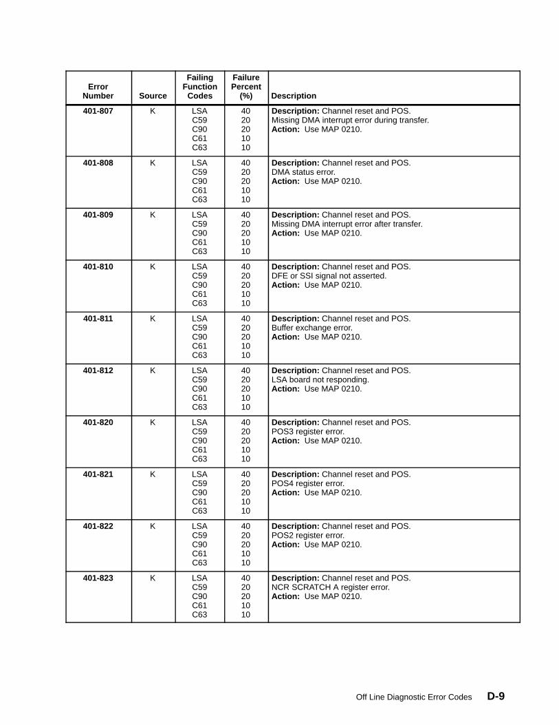
Off Line Diagnostic Error Codes D-9
ErrorNumber
Description
FailurePercent
(%)
FailingFunction
CodesSource
401-807 K LSAC59C90C61C63
4020201010
Description: Channel reset and POS.Missing DMA interrupt error during transfer.Action: Use MAP 0210.
401-808 K LSAC59C90C61C63
4020201010
Description: Channel reset and POS.DMA status error.Action: Use MAP 0210.
401-809 K LSAC59C90C61C63
4020201010
Description: Channel reset and POS.Missing DMA interrupt error after transfer.Action: Use MAP 0210.
401-810 K LSAC59C90C61C63
4020201010
Description: Channel reset and POS.DFE or SSI signal not asserted.Action: Use MAP 0210.
401-811 K LSAC59C90C61C63
4020201010
Description: Channel reset and POS.Buffer exchange error.Action: Use MAP 0210.
401-812 K LSAC59C90C61C63
4020201010
Description: Channel reset and POS.LSA board not responding.Action: Use MAP 0210.
401-820 K LSAC59C90C61C63
4020201010
Description: Channel reset and POS.POS3 register error.Action: Use MAP 0210.
401-821 K LSAC59C90C61C63
4020201010
Description: Channel reset and POS.POS4 register error.Action: Use MAP 0210.
401-822 K LSAC59C90C61C63
4020201010
Description: Channel reset and POS.POS2 register error.Action: Use MAP 0210.
401-823 K LSAC59C90C61C63
4020201010
Description: Channel reset and POS.NCR SCRATCH A register error.Action: Use MAP 0210.

Service GuideD-10
ErrorNumber
Description
FailurePercent
(%)
FailingFunction
CodesSource
401-824 K LSAC59C90C61C63
4020201010
Description: Channel reset and POS.SCSI Bus control lines error.Action: Use MAP 0210.
401-825 K LSAC59C90C61C63
4020201010
Description: Channel reset and POS.Missing ACK signal error.Action: Use MAP 0210.
401-826 K LSAC59C90C61C63
4020201010
Description: Channel reset and POS.Pending ACK signal error.Action: Use MAP 0210.
401-827 K LSAC59C90C61C63
4020201010
Description: Channel reset and POS.Missing DMA interrupt error during transfer.Action: Use MAP 0210.
401-828 K LSAC59C90C61C63
4020201010
Description: Channel reset and POS.DMA status error.Action: Use MAP 0210.
401-829 K LSAC59C90C61C63
4020201010
Description: Channel reset and POS.Missing DMA interrupt after transfer.Action: Use MAP 0210.
401-830 K LSAC59C90C61C63
4020201010
Description: Channel reset and POS.DFE or SSI signal not asserted.Action: Use MAP 0210.
401-831 K LSAC59C90C61C63
4020201010
Description: Channel reset and POS.Buffer exchange error.Action: Use MAP 0210.
401-832 K LSAC59C90C61C63
4020201010
Description: Channel reset and POS.LSA board not responding.Action: Use MAP 0210.
401-840 K LSAC59C90C61C63
4020201010
Description: Channel reset and POS.POS3 register error.Action: Use MAP 0210.
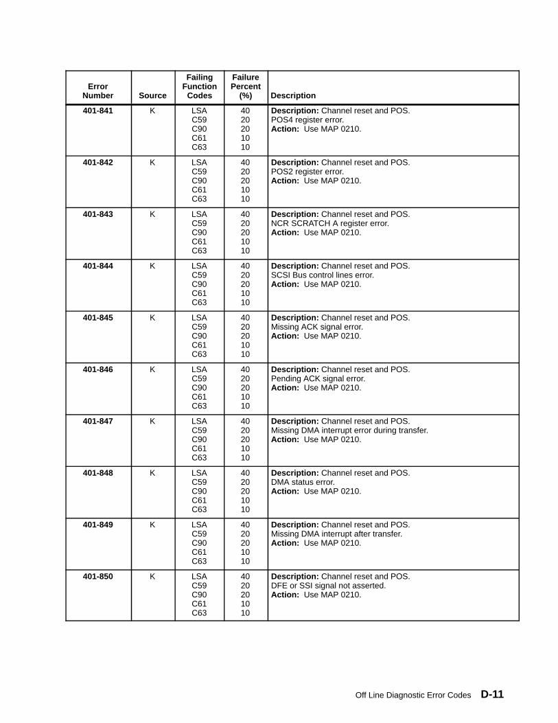
Off Line Diagnostic Error Codes D-11
ErrorNumber
Description
FailurePercent
(%)
FailingFunction
CodesSource
401-841 K LSAC59C90C61C63
4020201010
Description: Channel reset and POS.POS4 register error.Action: Use MAP 0210.
401-842 K LSAC59C90C61C63
4020201010
Description: Channel reset and POS.POS2 register error.Action: Use MAP 0210.
401-843 K LSAC59C90C61C63
4020201010
Description: Channel reset and POS.NCR SCRATCH A register error.Action: Use MAP 0210.
401-844 K LSAC59C90C61C63
4020201010
Description: Channel reset and POS.SCSI Bus control lines error.Action: Use MAP 0210.
401-845 K LSAC59C90C61C63
4020201010
Description: Channel reset and POS.Missing ACK signal error.Action: Use MAP 0210.
401-846 K LSAC59C90C61C63
4020201010
Description: Channel reset and POS.Pending ACK signal error.Action: Use MAP 0210.
401-847 K LSAC59C90C61C63
4020201010
Description: Channel reset and POS.Missing DMA interrupt error during transfer.Action: Use MAP 0210.
401-848 K LSAC59C90C61C63
4020201010
Description: Channel reset and POS.DMA status error.Action: Use MAP 0210.
401-849 K LSAC59C90C61C63
4020201010
Description: Channel reset and POS.Missing DMA interrupt after transfer.Action: Use MAP 0210.
401-850 K LSAC59C90C61C63
4020201010
Description: Channel reset and POS.DFE or SSI signal not asserted.Action: Use MAP 0210.

Service GuideD-12
ErrorNumber
Description
FailurePercent
(%)
FailingFunction
CodesSource
401-851 K LSAC59C90C61C63
4020201010
Description: Channel reset and POS.Buffer exchange error.Action: Use MAP 0210.
401-852 K LSAC59C90C61C63
4020201010
Description: Channel reset and POS.LSA board not responding.Action: Use MAP 0210.
402-000 K C63 100 Description: CPU processor error.Action: Use MAP 0210.
402-010 K C63 100 Description: Main memory addressing mechanism error.Action: Use MAP 0210.
402-011 K C63 100 Description: Main memory addressing mechanism.BAT translation error.Action: Use MAP 0210.
402-012 K C63 100 Description: Main memory addressing mechanism.Swap context PTE1 error.Action: Use MAP 0210.
402-013 K C63 100 Description: Main memory addressing mechanism.Swap context PTE2 error.Action: Use MAP 0210.
402-020 K C63 100 Description: Level 1 cache. HID0.31 value error.Action: Use MAP 0210.
402-030 K C63 100 Description: Level 2 cache. Accessibility test error.Action: Use MAP 0210.
402-031 K C63 100 Description: Level 2 cache. Data test error Action: Use MAP 0210.
402-032 K C63 100 Description: Level 2 cache. TAG test error.Action: Use MAP 0210.
402-033 K C63 100 Description: Level 2 cache. Interrupt error.Action: Use MAP 0210.
402-040 K C62C63C65
100100100
Description: EEprom compatibility error.Action: Use MAP 0210.
402-100 K C63C61
5050
Description: Atomic instructions error.Memory reservation by slave processor lack. Action: Use MAP 0210.
402-101 K C63C61
5050
Description: Atomic instructions error.Memory reservation by master processor lack.Action: Use MAP 0210.
402-102 K C63C61
5050
Description: Atomic instructions error.Comparison error.Action: Use MAP 0210.
402-103 K C62C63C65
100100100
Description: Atomic instructions error. Swap mechanism notavailable.Action: Use MAP 0210.
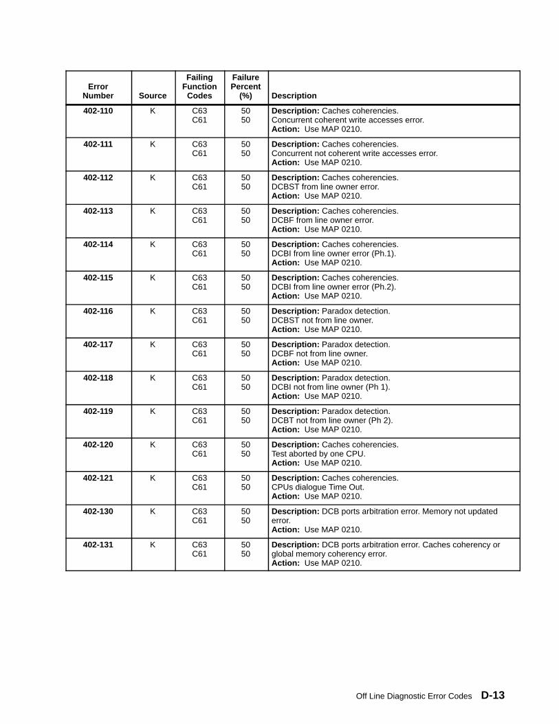
Off Line Diagnostic Error Codes D-13
ErrorNumber Source
FailingFunction
Codes
FailurePercent
(%)
Description
402-110 K C63C61
5050
Description: Caches coherencies.Concurrent coherent write accesses error.Action: Use MAP 0210.
402-111 K C63C61
5050
Description: Caches coherencies.Concurrent not coherent write accesses error.Action: Use MAP 0210.
402-112 K C63C61
5050
Description: Caches coherencies.DCBST from line owner error.Action: Use MAP 0210.
402-113 K C63C61
5050
Description: Caches coherencies.DCBF from line owner error.Action: Use MAP 0210.
402-114 K C63C61
5050
Description: Caches coherencies.DCBI from line owner error (Ph.1).Action: Use MAP 0210.
402-115 K C63C61
5050
Description: Caches coherencies.DCBI from line owner error (Ph.2).Action: Use MAP 0210.
402-116 K C63C61
5050
Description: Paradox detection.DCBST not from line owner.Action: Use MAP 0210.
402-117 K C63C61
5050
Description: Paradox detection.DCBF not from line owner.Action: Use MAP 0210.
402-118 K C63C61
5050
Description: Paradox detection.DCBI not from line owner (Ph 1).Action: Use MAP 0210.
402-119 K C63C61
5050
Description: Paradox detection.DCBT not from line owner (Ph 2).Action: Use MAP 0210.
402-120 K C63C61
5050
Description: Caches coherencies.Test aborted by one CPU.Action: Use MAP 0210.
402-121 K C63C61
5050
Description: Caches coherencies.CPUs dialogue Time Out.Action: Use MAP 0210.
402-130 K C63C61
5050
Description: DCB ports arbitration error. Memory not updatederror.Action: Use MAP 0210.
402-131 K C63C61
5050
Description: DCB ports arbitration error. Caches coherency orglobal memory coherency error.Action: Use MAP 0210.
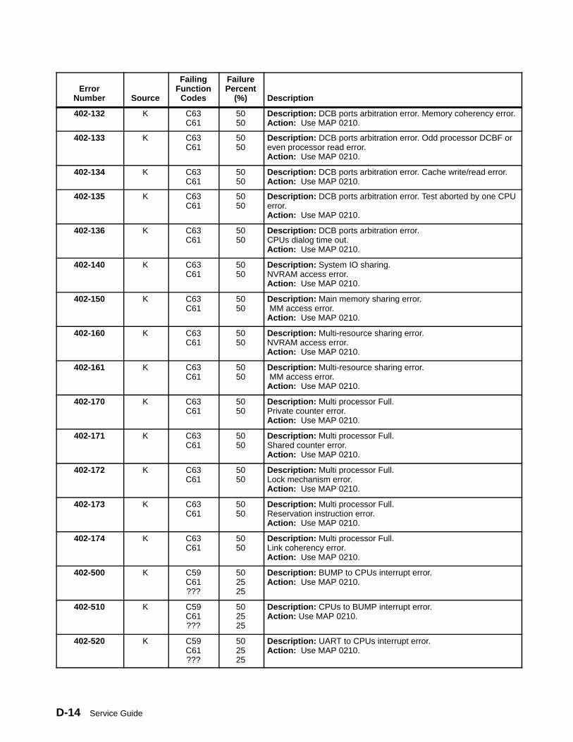
Service GuideD-14
ErrorNumber Source
FailingFunction
Codes
FailurePercent
(%)
Description
402-132 K C63C61
5050
Description: DCB ports arbitration error. Memory coherency error.Action: Use MAP 0210.
402-133 K C63C61
5050
Description: DCB ports arbitration error. Odd processor DCBF oreven processor read error.Action: Use MAP 0210.
402-134 K C63C61
5050
Description: DCB ports arbitration error. Cache write/read error.Action: Use MAP 0210.
402-135 K C63C61
5050
Description: DCB ports arbitration error. Test aborted by one CPUerror.Action: Use MAP 0210.
402-136 K C63C61
5050
Description: DCB ports arbitration error.CPUs dialog time out.Action: Use MAP 0210.
402-140 K C63C61
5050
Description: System IO sharing.NVRAM access error.Action: Use MAP 0210.
402-150 K C63C61
5050
Description: Main memory sharing error. MM access error.Action: Use MAP 0210.
402-160 K C63C61
5050
Description: Multi-resource sharing error.NVRAM access error.Action: Use MAP 0210.
402-161 K C63C61
5050
Description: Multi-resource sharing error. MM access error.Action: Use MAP 0210.
402-170 K C63C61
5050
Description: Multi processor Full.Private counter error.Action: Use MAP 0210.
402-171 K C63C61
5050
Description: Multi processor Full.Shared counter error.Action: Use MAP 0210.
402-172 K C63C61
5050
Description: Multi processor Full.Lock mechanism error.Action: Use MAP 0210.
402-173 K C63C61
5050
Description: Multi processor Full.Reservation instruction error.Action: Use MAP 0210.
402-174 K C63C61
5050
Description: Multi processor Full.Link coherency error.Action: Use MAP 0210.
402-500 K C59C61???
502525
Description: BUMP to CPUs interrupt error.Action: Use MAP 0210.
402-510 K C59C61???
502525
Description: CPUs to BUMP interrupt error.Action: Use MAP 0210.
402-520 K C59C61???
502525
Description: UART to CPUs interrupt error.Action: Use MAP 0210.
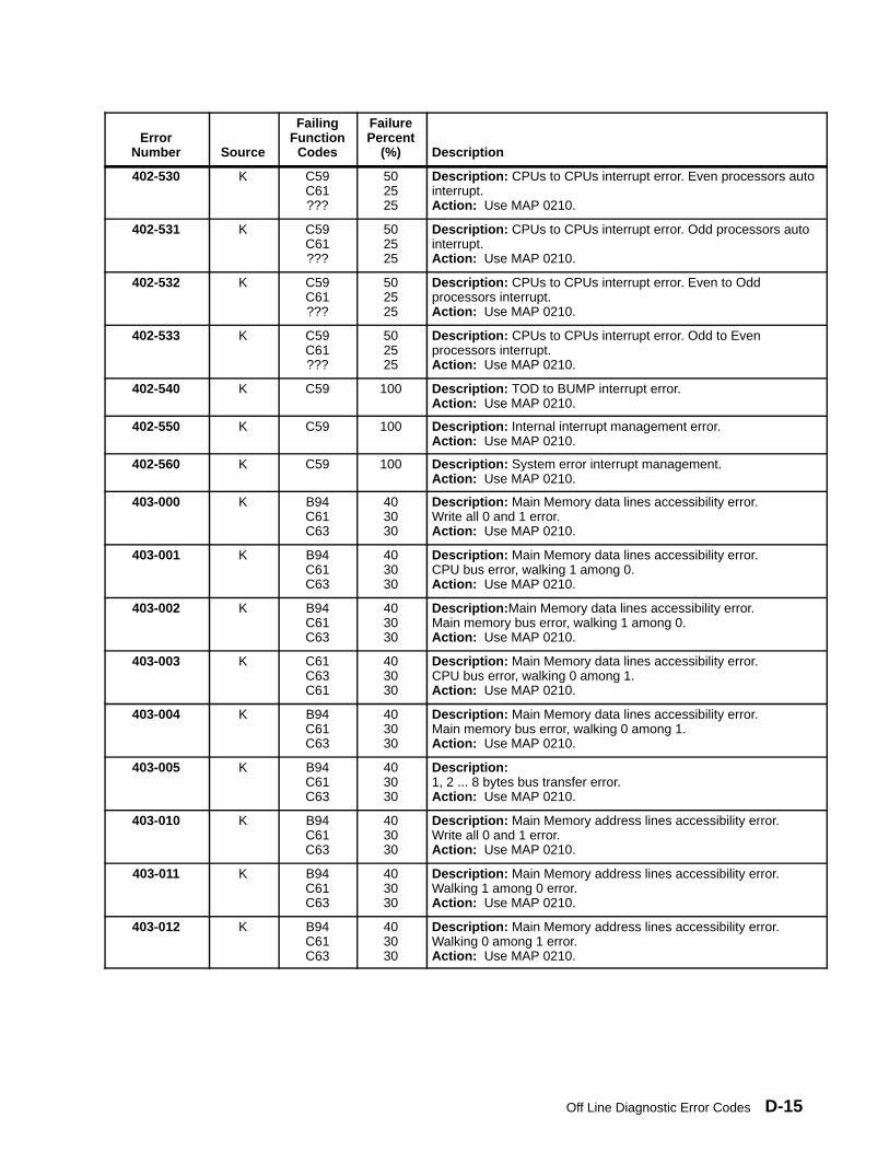
Off Line Diagnostic Error Codes D-15
ErrorNumber Source
FailingFunction
Codes
FailurePercent
(%)
Description
402-530 K C59C61???
502525
Description: CPUs to CPUs interrupt error. Even processors autointerrupt.Action: Use MAP 0210.
402-531 K C59C61???
502525
Description: CPUs to CPUs interrupt error. Odd processors autointerrupt.Action: Use MAP 0210.
402-532 K C59C61???
502525
Description: CPUs to CPUs interrupt error. Even to Oddprocessors interrupt.Action: Use MAP 0210.
402-533 K C59C61???
502525
Description: CPUs to CPUs interrupt error. Odd to Evenprocessors interrupt.Action: Use MAP 0210.
402-540 K C59 100 Description: TOD to BUMP interrupt error.Action: Use MAP 0210.
402-550 K C59 100 Description: Internal interrupt management error.Action: Use MAP 0210.
402-560 K C59 100 Description: System error interrupt management.Action: Use MAP 0210.
403-000 K B94C61C63
403030
Description: Main Memory data lines accessibility error.Write all 0 and 1 error.Action: Use MAP 0210.
403-001 K B94C61C63
403030
Description: Main Memory data lines accessibility error.CPU bus error, walking 1 among 0.Action: Use MAP 0210.
403-002 K B94C61C63
403030
Description: Main Memory data lines accessibility error.Main memory bus error, walking 1 among 0.Action: Use MAP 0210.
403-003 K C61C63C61
403030
Description: Main Memory data lines accessibility error.CPU bus error, walking 0 among 1.Action: Use MAP 0210.
403-004 K B94C61C63
403030
Description: Main Memory data lines accessibility error.Main memory bus error, walking 0 among 1.Action: Use MAP 0210.
403-005 K B94C61C63
403030
Description: 1, 2 ... 8 bytes bus transfer error.Action: Use MAP 0210.
403-010 K B94C61C63
403030
Description: Main Memory address lines accessibility error.Write all 0 and 1 error.Action: Use MAP 0210.
403-011 K B94C61C63
403030
Description: Main Memory address lines accessibility error.Walking 1 among 0 error.Action: Use MAP 0210.
403-012 K B94C61C63
403030
Description: Main Memory address lines accessibility error.Walking 0 among 1 error.Action: Use MAP 0210.
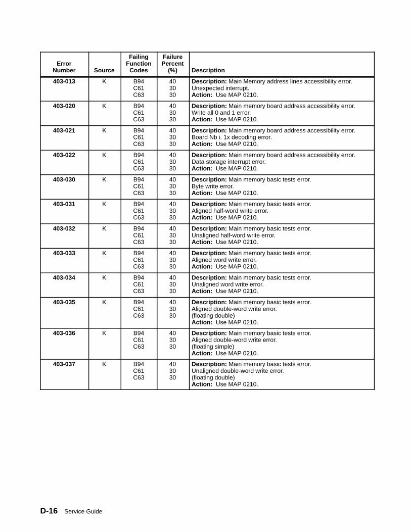
Service GuideD-16
ErrorNumber Source
FailingFunction
Codes
FailurePercent
(%)
Description
403-013 K B94C61C63
403030
Description: Main Memory address lines accessibility error.Unexpected interrupt.Action: Use MAP 0210.
403-020 K B94C61C63
403030
Description: Main memory board address accessibility error.Write all 0 and 1 error.Action: Use MAP 0210.
403-021 K B94C61C63
403030
Description: Main memory board address accessibility error.Board Nb i. 1x decoding error.Action: Use MAP 0210.
403-022 K B94C61C63
403030
Description: Main memory board address accessibility error.Data storage interrupt error.Action: Use MAP 0210.
403-030 K B94C61C63
403030
Description: Main memory basic tests error.Byte write error.Action: Use MAP 0210.
403-031 K B94C61C63
403030
Description: Main memory basic tests error.Aligned half-word write error.Action: Use MAP 0210.
403-032 K B94C61C63
403030
Description: Main memory basic tests error.Unaligned half-word write error.Action: Use MAP 0210.
403-033 K B94C61C63
403030
Description: Main memory basic tests error.Aligned word write error.Action: Use MAP 0210.
403-034 K B94C61C63
403030
Description: Main memory basic tests error.Unaligned word write error.Action: Use MAP 0210.
403-035 K B94C61C63
403030
Description: Main memory basic tests error.Aligned double-word write error.(floating double)Action: Use MAP 0210.
403-036 K B94C61C63
403030
Description: Main memory basic tests error.Aligned double-word write error.(floating simple)Action: Use MAP 0210.
403-037 K B94C61C63
403030
Description: Main memory basic tests error.Unaligned double-word write error.(floating double)Action: Use MAP 0210.
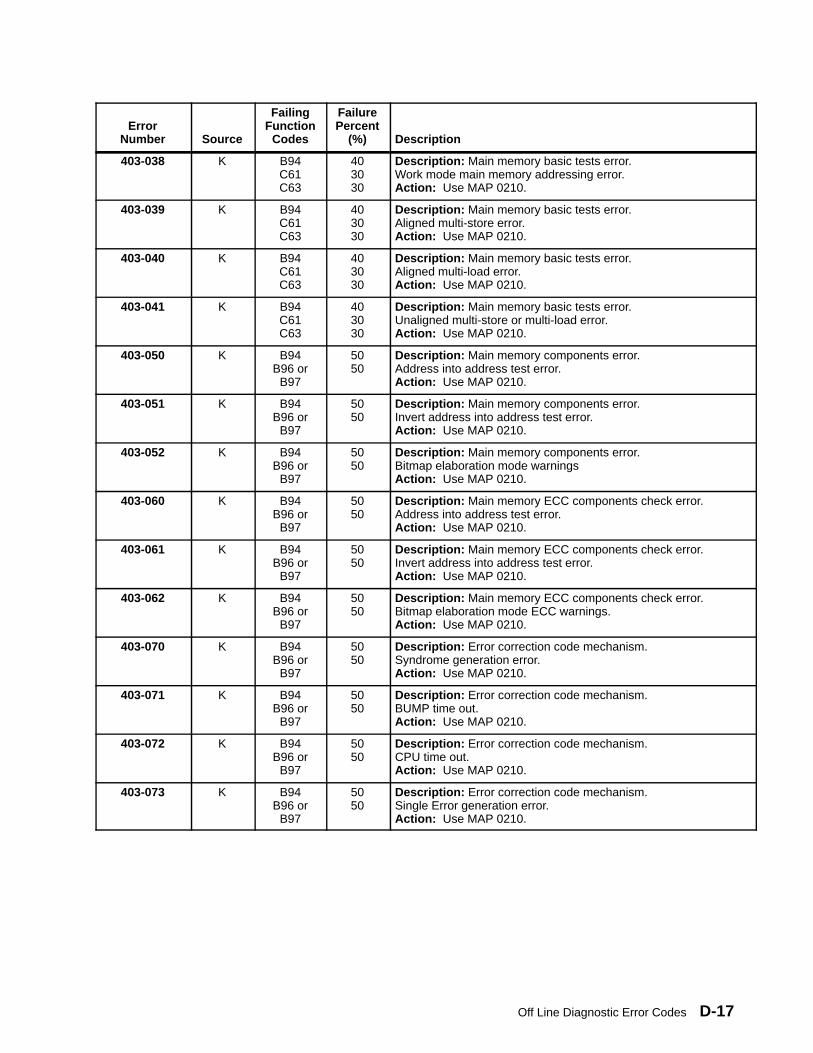
Off Line Diagnostic Error Codes D-17
ErrorNumber Source
FailingFunction
Codes
FailurePercent
(%)
Description
403-038 K B94C61C63
403030
Description: Main memory basic tests error.Work mode main memory addressing error.Action: Use MAP 0210.
403-039 K B94C61C63
403030
Description: Main memory basic tests error.Aligned multi-store error.Action: Use MAP 0210.
403-040 K B94C61C63
403030
Description: Main memory basic tests error.Aligned multi-load error.Action: Use MAP 0210.
403-041 K B94C61C63
403030
Description: Main memory basic tests error.Unaligned multi-store or multi-load error.Action: Use MAP 0210.
403-050 K B94B96 or
B97
5050
Description: Main memory components error.Address into address test error.Action: Use MAP 0210.
403-051 K B94B96 or
B97
5050
Description: Main memory components error.Invert address into address test error.Action: Use MAP 0210.
403-052 K B94B96 or
B97
5050
Description: Main memory components error.Bitmap elaboration mode warningsAction: Use MAP 0210.
403-060 K B94B96 or
B97
5050
Description: Main memory ECC components check error.Address into address test error.Action: Use MAP 0210.
403-061 K B94B96 or
B97
5050
Description: Main memory ECC components check error.Invert address into address test error.Action: Use MAP 0210.
403-062 K B94B96 or
B97
5050
Description: Main memory ECC components check error.Bitmap elaboration mode ECC warnings.Action: Use MAP 0210.
403-070 K B94B96 or
B97
5050
Description: Error correction code mechanism.Syndrome generation error.Action: Use MAP 0210.
403-071 K B94B96 or
B97
5050
Description: Error correction code mechanism.BUMP time out.Action: Use MAP 0210.
403-072 K B94B96 or
B97
5050
Description: Error correction code mechanism.CPU time out.Action: Use MAP 0210.
403-073 K B94B96 or
B97
5050
Description: Error correction code mechanism.Single Error generation error.Action: Use MAP 0210.
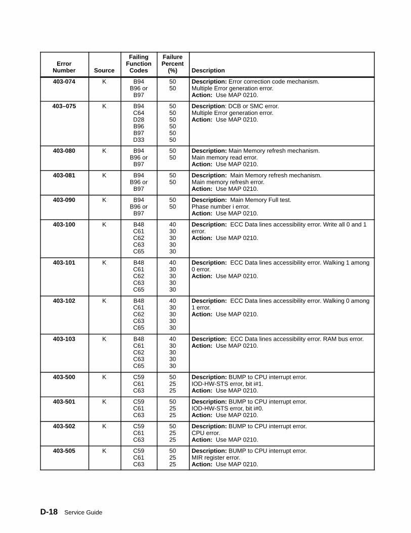
Service GuideD-18
ErrorNumber Source
FailingFunction
Codes
FailurePercent
(%)
Description
403-074 K B94B96 or
B97
5050
Description: Error correction code mechanism.Multiple Error generation error.Action: Use MAP 0210.
403–075 K B94C64D28B96B97D33
505050505050
Description : DCB or SMC error.Multiple Error generation error.Action: Use MAP 0210.
403-080 K B94B96 or
B97
5050
Description: Main Memory refresh mechanism.Main memory read error.Action: Use MAP 0210.
403-081 K B94B96 or
B97
5050
Description: Main Memory refresh mechanism.Main memory refresh error.Action: Use MAP 0210.
403-090 K B94B96 or
B97
5050
Description: Main Memory Full test.Phase number i error.Action: Use MAP 0210.
403-100 K B48C61C62C63C65
4030303030
Description: ECC Data lines accessibility error. Write all 0 and 1error.Action: Use MAP 0210.
403-101 K B48C61C62C63C65
4030303030
Description: ECC Data lines accessibility error. Walking 1 among0 error.Action: Use MAP 0210.
403-102 K B48C61C62C63C65
4030303030
Description: ECC Data lines accessibility error. Walking 0 among1 error.Action: Use MAP 0210.
403-103 K B48C61C62C63C65
4030303030
Description: ECC Data lines accessibility error. RAM bus error.Action: Use MAP 0210.
403-500 K C59C61C63
502525
Description: BUMP to CPU interrupt error.IOD-HW-STS error, bit i#1.Action: Use MAP 0210.
403-501 K C59C61C63
502525
Description: BUMP to CPU interrupt error.IOD-HW-STS error, bit i#0.Action: Use MAP 0210.
403-502 K C59C61C63
502525
Description: BUMP to CPU interrupt error.CPU error.Action: Use MAP 0210.
403-505 K C59C61C63
502525
Description: BUMP to CPU interrupt error.MIR register error.Action: Use MAP 0210.
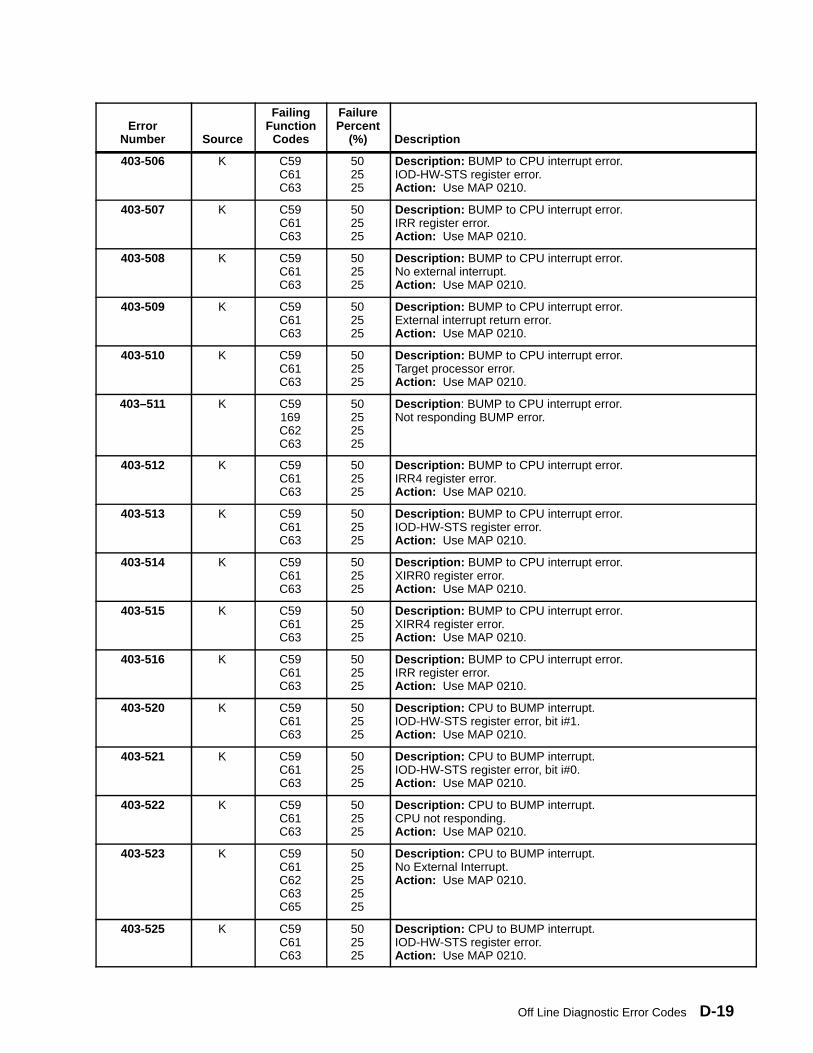
Off Line Diagnostic Error Codes D-19
ErrorNumber
Description
FailurePercent
(%)
FailingFunction
CodesSource
403-506 K C59C61C63
502525
Description: BUMP to CPU interrupt error.IOD-HW-STS register error.Action: Use MAP 0210.
403-507 K C59C61C63
502525
Description: BUMP to CPU interrupt error.IRR register error.Action: Use MAP 0210.
403-508 K C59C61C63
502525
Description: BUMP to CPU interrupt error.No external interrupt.Action: Use MAP 0210.
403-509 K C59C61C63
502525
Description: BUMP to CPU interrupt error.External interrupt return error.Action: Use MAP 0210.
403-510 K C59C61C63
502525
Description: BUMP to CPU interrupt error.Target processor error.Action: Use MAP 0210.
403–511 K C59169C62C63
50252525
Description : BUMP to CPU interrupt error.Not responding BUMP error.
403-512 K C59C61C63
502525
Description: BUMP to CPU interrupt error.IRR4 register error.Action: Use MAP 0210.
403-513 K C59C61C63
502525
Description: BUMP to CPU interrupt error.IOD-HW-STS register error.Action: Use MAP 0210.
403-514 K C59C61C63
502525
Description: BUMP to CPU interrupt error.XIRR0 register error.Action: Use MAP 0210.
403-515 K C59C61C63
502525
Description: BUMP to CPU interrupt error.XIRR4 register error.Action: Use MAP 0210.
403-516 K C59C61C63
502525
Description: BUMP to CPU interrupt error.IRR register error.Action: Use MAP 0210.
403-520 K C59C61C63
502525
Description: CPU to BUMP interrupt.IOD-HW-STS register error, bit i#1.Action: Use MAP 0210.
403-521 K C59C61C63
502525
Description: CPU to BUMP interrupt.IOD-HW-STS register error, bit i#0.Action: Use MAP 0210.
403-522 K C59C61C63
502525
Description: CPU to BUMP interrupt.CPU not responding.Action: Use MAP 0210.
403-523 K C59C61C62C63C65
5025252525
Description: CPU to BUMP interrupt.No External Interrupt.Action: Use MAP 0210.
403-525 K C59C61C63
502525
Description: CPU to BUMP interrupt.IOD-HW-STS register error.Action: Use MAP 0210.
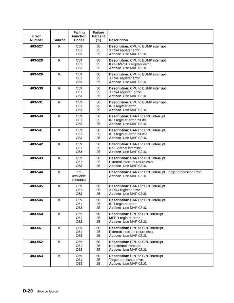
Service GuideD-20
ErrorNumber
Description
FailurePercent
(%)
FailingFunction
CodesSource
403-527 K C59C61C63
502525
Description: CPU to BUMP interrupt.XIRR4 register error.Action: Use MAP 0210.
403-528 K C59C61C63
502525
Description: CPU to BUMP interrupt.IOD-HW-STS register error.Action: Use MAP 0210.
403-529 K C59C61C63
502525
Description: CPU to BUMP interrupt.XIRR0 register error.Action: Use MAP 0210.
403-530 K C59C61C63
502525
Description: CPU to BUMP interrupt.XIRR4 register error.Action: Use MAP 0210.
403-531 K C59C61C63
502525
Description: CPU to BUMP interrupt.IRR register error.Action: Use MAP 0210.
403-540 K C59C61C63
502525
Description: UART to CPU interrupt.IRR register error, bit i#1.Action: Use MAP 0210.
403-541 K C59C61C63
502525
Description: UART to CPU interrupt.IRR register error, bit i#0.Action: Use MAP 0210.
403-542 K C59C61C63
502525
Description: UART to CPU interrupt.No External interrupt.Action: Use MAP 0210.
403-543 K C59C61C63
502525
Description: UART to CPU interrupt.External interrupt return error.Action: Use MAP 0210.
403-544 K notavailableresource
Description: UART to CPU interrupt. Target processor error.Action: Use MAP 0210.
403-545 K C59C61C63
502525
Description: UART to CPU interrupt.XIRR4 register error.Action: Use MAP 0210.
403-546 K C59C61C63
502525
Description: UART to CPU interrupt.IRR register error.Action: Use MAP 0210.
403-550 K C59C61C63
502525
Description: CPU to CPU interrupt.MFRR register error.Action: Use MAP 0210.
403-551 K C59C61C63
502525
Description: CPU to CPU interrupt.External interrupt return error.Action: Use MAP 0210.
403-552 K C59C61C63
502525
Description: CPU to CPU interrupt.No external interrupt.Action: Use MAP 0210.
403-553 K C59C61C63
502525
Description: CPU to CPU interrupt.Target processor error.Action: Use MAP 0210.

Off Line Diagnostic Error Codes D-21
ErrorNumber
Description
FailurePercent
(%)
FailingFunction
CodesSource
403-555 K C59C61C63
502525
Description: CPU to CPU interrupt.XIRR register error.Action: Use MAP 0210.
403-560 K C59C61C63
502525
Description: TOD to BUMP interrupt.Unexpected interrupt error.Action: Use MAP 0210.
403-561 K C59C61C63
502525
Description: TOD to BUMP interrupt.No trap interrupt.Action: Use MAP 0210.
403-563 K C59C61C62C63C65
5025252525
Description: TOD to BUMP interrupt.MSR register error. BUMP interrupt management.Action: Use MAP 0210.
403-565 K Description: MCA to CPU interrupt.All slots plugged with MCA boards.Action: Use MAP 0210.
403-566 K 909 100 Description: MCA to CPU interrupt. LSA board not responding.No interrupt on a PIO STORE with buid # on slot #.Action: Use MAP 0210.
403-567 K 909 100 Description: MCA to CPU interrupt. LSA board not responding.No interrupt on a PIO STORE with buid # on slot #.Action: Use MAP 0210.
404-000 K C63C61
8020
Description: Atomic instructions error.Action: Use MAP 0210.
404-002 K C88 100 Description: EPROM Checksum values error.
404-010 K C63C61
8020
Description: Caches coherencies.Concurrent coherent write accesses error.Action: Use MAP 0210.
404-011 K C63C61
8020
Description: Caches coherencies.Concurrent not coherent write accesses error.Action: Use MAP 0210.
404-012 K C63C61
8020
Description: Caches coherencies.DCBST from line owner error.Action: Use MAP 0210.
404-013 K C63C61
8020
Description: Caches coherencies.DCBF from line owner error.Action: Use MAP 0210.
404-014 K C63C61
8020
Description: Caches coherencies.DCBI from line owner error.Action: Use MAP 0210.
404-015 K C63C61
8020
Description: Caches coherencies.Concurrent not coherent write accesses error.Action: Use MAP 0210.
404-016 K C63C61
8020
Description: Caches coherencies.DCBST not from line owner error.Action: Use MAP 0210.
404-017 K C63C61
8020
Description: Caches coherencies.DCBF not from line owner error.Action: Use MAP 0210.
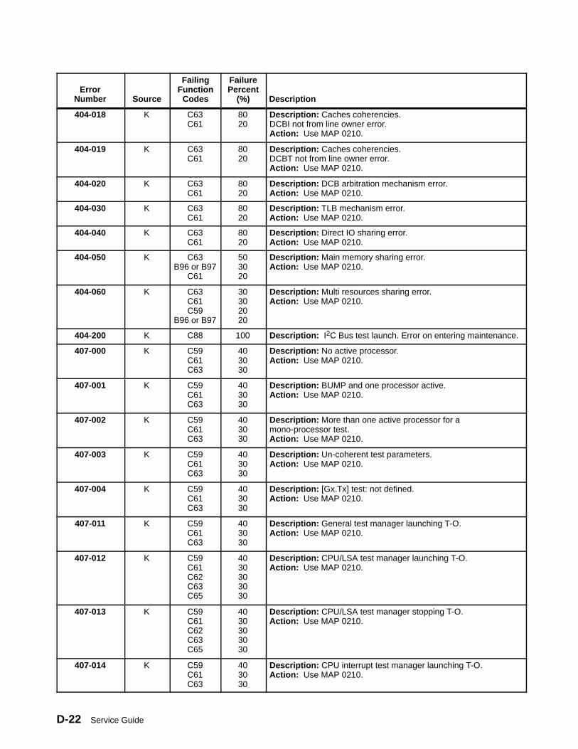
Service GuideD-22
ErrorNumber
Description
FailurePercent
(%)
FailingFunction
CodesSource
404-018 K C63C61
8020
Description: Caches coherencies.DCBI not from line owner error.Action: Use MAP 0210.
404-019 K C63C61
8020
Description: Caches coherencies.DCBT not from line owner error.Action: Use MAP 0210.
404-020 K C63C61
8020
Description: DCB arbitration mechanism error.Action: Use MAP 0210.
404-030 K C63C61
8020
Description: TLB mechanism error.Action: Use MAP 0210.
404-040 K C63C61
8020
Description: Direct IO sharing error.Action: Use MAP 0210.
404-050 K C63B96 or B97
C61
503020
Description: Main memory sharing error.Action: Use MAP 0210.
404-060 K C63C61C59
B96 or B97
30302020
Description: Multi resources sharing error.Action: Use MAP 0210.
404-200 K C88 100 Description: I2C Bus test launch. Error on entering maintenance.
407-000 K C59C61C63
403030
Description: No active processor.Action: Use MAP 0210.
407-001 K C59C61C63
403030
Description: BUMP and one processor active.Action: Use MAP 0210.
407-002 K C59C61C63
403030
Description: More than one active processor for amono-processor test.Action: Use MAP 0210.
407-003 K C59C61C63
403030
Description: Un-coherent test parameters.Action: Use MAP 0210.
407-004 K C59C61C63
403030
Description: [Gx.Tx] test: not defined.Action: Use MAP 0210.
407-011 K C59C61C63
403030
Description: General test manager launching T-O.Action: Use MAP 0210.
407-012 K C59C61C62C63C65
4030303030
Description: CPU/LSA test manager launching T-O.Action: Use MAP 0210.
407-013 K C59C61C62C63C65
4030303030
Description: CPU/LSA test manager stopping T-O.Action: Use MAP 0210.
407-014 K C59C61C63
403030
Description: CPU interrupt test manager launching T-O.Action: Use MAP 0210.
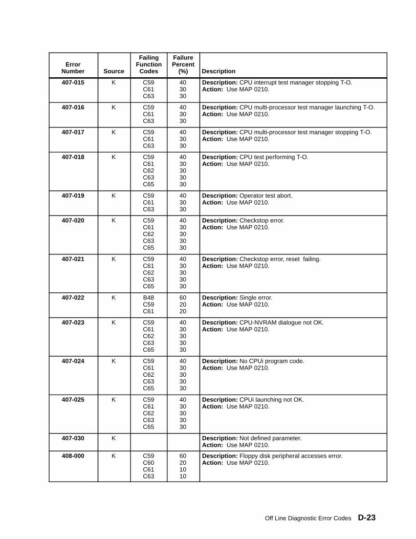
Off Line Diagnostic Error Codes D-23
ErrorNumber
Description
FailurePercent
(%)
FailingFunction
CodesSource
407-015 K C59C61C63
403030
Description: CPU interrupt test manager stopping T-O. Action: Use MAP 0210.
407-016 K C59C61C63
403030
Description: CPU multi-processor test manager launching T-O. Action: Use MAP 0210.
407-017 K C59C61C63
403030
Description: CPU multi-processor test manager stopping T-O.Action: Use MAP 0210.
407-018 K C59C61C62C63C65
4030303030
Description: CPU test performing T-O.Action: Use MAP 0210.
407-019 K C59C61C63
403030
Description: Operator test abort.Action: Use MAP 0210.
407-020 K C59C61C62C63C65
4030303030
Description: Checkstop error.Action: Use MAP 0210.
407-021 K C59C61C62C63C65
4030303030
Description: Checkstop error, reset failing.Action: Use MAP 0210.
407-022 K B48C59C61
602020
Description: Single error.Action: Use MAP 0210.
407-023 K C59C61C62C63C65
4030303030
Description: CPU-NVRAM dialogue not OK.Action: Use MAP 0210.
407-024 K C59C61C62C63C65
4030303030
Description: No CPUi program code.Action: Use MAP 0210.
407-025 K C59C61C62C63C65
4030303030
Description: CPUi launching not OK.Action: Use MAP 0210.
407-030 K Description: Not defined parameter.Action: Use MAP 0210.
408-000 K C59C60C61C63
60201010
Description: Floppy disk peripheral accesses error.Action: Use MAP 0210.

Service GuideD-24
ErrorNumber
Description
FailurePercent
(%)
FailingFunction
CodesSource
408-060 K B94B96 or
B97
5050
Description: Main memory Knaizuk-Hartmann test error.Action: Use MAP 0210.
408-080 K C63C61
9010
Description: Multi resources full test error.Action: Use MAP 0210.
409-000 K ??? 100 Description: Planar vital part FATAL ERROR.Action: Use MAP 0210.
409-008 K B94 or C64or D28
100 Description: No 2MB available in MM. All memory banks FATALERROR.Action: Use MAP 0210.
409–050 K None None Description : This is not an error. This code indicates a change inconfiguration, that NV-RAM has been reset, etc. No parts shouldbe replaced for this code.
409–051 K None None Description : This is not an error. This code indicates a change inconfiguration, that NV-RAM has been reset, etc. No parts shouldbe replaced for this code.
409–052 T1 x K Firmware 100 Description : –12 stand–by VOLT error. x is the unit number.
409–052 T2 x K Firmware 100 Description : +12 stand–by VOLT error. x is the unit number.
409–053 T1 x K Firmware 100 Description : 485RX protocol error (lengths). x is the unit number.
409–053 T2 x K Firmware 100 Description : 485RX protocol error (time–out). x is the unit number.
409–053 T3 x K Firmware 100 Description : 485RX protocol error (checksum error). x is the unitnumber.
409–054 T1 K Firmware 100 Description : Marginature error (ASIC VOLT).
409–054 T2 K Firmware 100 Description : Marginature error (CPU VOLT).
409–054 T3 x K Firmware 100 Description : Marginature error (+5 VOLT). x is the unit number.
409–055 T1 K Firmware 100 Description : VPD command error (read VPD).
409–055 T2 K Firmware 100 Description : VPD command error (writeVPD).
409–056 K Firmware 100 Description : Marginature command error.
409–057 K Firmware 100 Description : Checksum logging not valid.
409–058 K Firmware 100 Description : Environment over temperature.
409–059 T1 K Firmware 100 Description : I2C bus error (wrong interrupt frame).
409–059 T2 x K Firmware 100 Description : I2C bus error ( unknown SIB interrupt). x is the unitnumber.
409–059 T3 x K Firmware 100 Description : I2C bus error ( unknown interrupt source). x is theunit number.
409–059 T4 x K Firmware 100 Description : I2C bus error ( unknown operator panel interrupt).x is the unit number.
409-080 K C59C60
C88 or C89
333333
Description: BUMP access to OPP or OPP access to SIF failed.Action: Use MAP 0210.
409-081 K C59C88 or C89
5050
Description: BUMP access to SIF failed.Action: Use MAP 0210.
409-082 K C59C60
8020
Description: Operator panel cannot access the BUMP.Action: Use MAP 0210.Note: This problem can be caused by an incorrectly installed CEC.
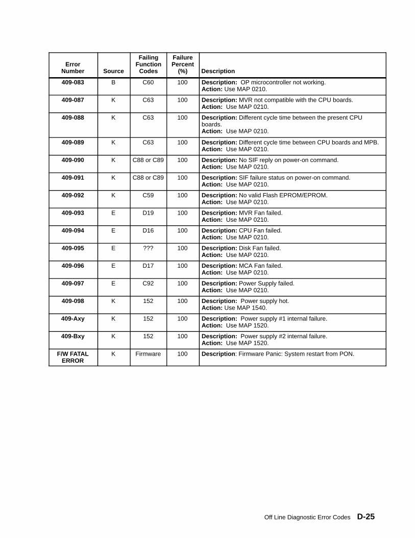
Off Line Diagnostic Error Codes D-25
ErrorNumber
Description
FailurePercent
(%)
FailingFunction
CodesSource
409-083 B C60 100 Description: OP microcontroller not working.Action: Use MAP 0210.
409-087 K C63 100 Description: MVR not compatible with the CPU boards.Action: Use MAP 0210.
409-088 K C63 100 Description: Different cycle time between the present CPUboards.Action: Use MAP 0210.
409-089 K C63 100 Description: Different cycle time between CPU boards and MPB.Action: Use MAP 0210.
409-090 K C88 or C89 100 Description: No SIF reply on power-on command.Action: Use MAP 0210.
409-091 K C88 or C89 100 Description: SIF failure status on power-on command.Action: Use MAP 0210.
409-092 K C59 100 Description: No valid Flash EPROM/EPROM.Action: Use MAP 0210.
409-093 E D19 100 Description: MVR Fan failed.Action: Use MAP 0210.
409-094 E D16 100 Description: CPU Fan failed.Action: Use MAP 0210.
409-095 E ??? 100 Description: Disk Fan failed.Action: Use MAP 0210.
409-096 E D17 100 Description: MCA Fan failed.Action: Use MAP 0210.
409-097 E C92 100 Description: Power Supply failed.Action: Use MAP 0210.
409-098 K 152 100 Description: Power supply hot.Action: Use MAP 1540.
409-Axy K 152 100 Description: Power supply #1 internal failure.Action: Use MAP 1520.
409-Bxy K 152 100 Description: Power supply #2 internal failure.Action: Use MAP 1520.
F/W FATALERROR
K Firmware 100 Description : Firmware Panic: System restart from PON.
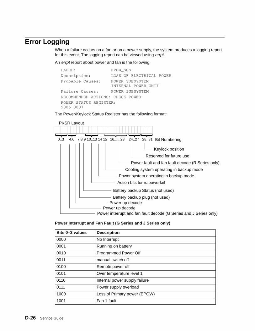
Service GuideD-26
Error LoggingWhen a failure occurs on a fan or on a power supply, the system produces a logging reportfor this event. The logging report can be viewed using errpt.
An errpt report about power and fan is the following:
LABEL: EPOW_SUS
Description: LOSS OF ELECTRICAL POWER
Probable Causes: POWER SUBSYSTEM INTERNAL POWER UNIT
Failure Causes: POWER SUBSYSTEM
RECOMMENDED ACTIONS: CHECK POWER
POWER STATUS REGISTER:9005 0007
The Power/Keylock Status Register has the following format:
PKSR Layout
0..3 4.6 7 8 9 10..13 14 15 16......23 24..27 28..31
Keylock position
Reserved for future use
Power fault and fan fault decode (R Series only)
Action bits for rc.powerfail
Battery backup Status (not used)
Battery backup plug (not used)
Power interrupt and fan fault decode (G Series and J Series only)
Cooling system operating in backup mode
Power system operating in backup mode
Power up decodePower up decode
Bit Numbering
Power Interrupt and Fan Fault (G Series and J Series only)
Bits 0–3 values Description
0000 No Interrupt
0001 Running on battery
0010 Programmed Power Off
0011 manual switch off
0100 Remote power off
0101 Over temperature level 1
0110 Internal power supply failure
0111 Power supply overload
1000 Loss of Primary power (EPOW)
1001 Fan 1 fault
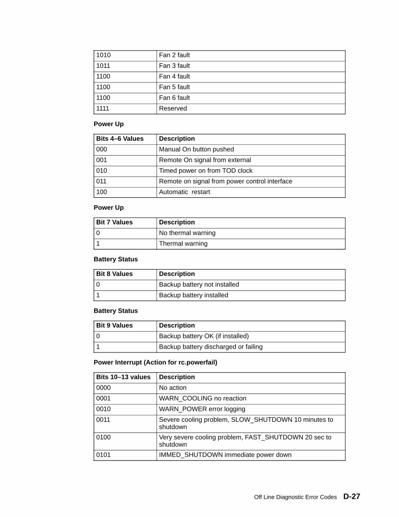
Off Line Diagnostic Error Codes D-27
1010 Fan 2 fault
1011 Fan 3 fault
1100 Fan 4 fault
1100 Fan 5 fault
1100 Fan 6 fault
1111 Reserved
Power Up
Bits 4–6 Values Description
000 Manual On button pushed
001 Remote On signal from external
010 Timed power on from TOD clock
011 Remote on signal from power control interface
100 Automatic restart
Power Up
Bit 7 Values Description
0 No thermal warning
1 Thermal warning
Battery Status
Bit 8 Values Description
0 Backup battery not installed
1 Backup battery installed
Battery Status
Bit 9 Values Description
0 Backup battery OK (if installed)
1 Backup battery discharged or failing
Power Interrupt (Action for rc.powerfail)
Bits 10–13 values Description
0000 No action
0001 WARN_COOLING no reaction
0010 WARN_POWER error logging
0011 Severe cooling problem, SLOW_SHUTDOWN 10 minutes toshutdown
0100 Very severe cooling problem, FAST_SHUTDOWN 20 sec toshutdown
0101 IMMED_SHUTDOWN immediate power down
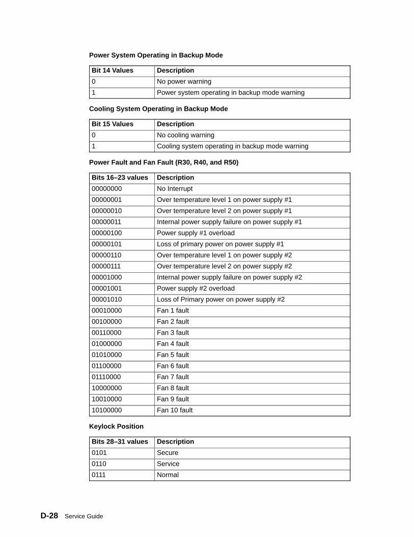
Service GuideD-28
Power System Operating in Backup Mode
Bit 14 Values Description
0 No power warning
1 Power system operating in backup mode warning
Cooling System Operating in Backup Mode
Bit 15 Values Description
0 No cooling warning
1 Cooling system operating in backup mode warning
Power Fault and Fan Fault (R30, R40, and R50)
Bits 16–23 values Description
00000000 No Interrupt
00000001 Over temperature level 1 on power supply #1
00000010 Over temperature level 2 on power supply #1
00000011 Internal power supply failure on power supply #1
00000100 Power supply #1 overload
00000101 Loss of primary power on power supply #1
00000110 Over temperature level 1 on power supply #2
00000111 Over temperature level 2 on power supply #2
00001000 Internal power supply failure on power supply #2
00001001 Power supply #2 overload
00001010 Loss of Primary power on power supply #2
00010000 Fan 1 fault
00100000 Fan 2 fault
00110000 Fan 3 fault
01000000 Fan 4 fault
01010000 Fan 5 fault
01100000 Fan 6 fault
01110000 Fan 7 fault
10000000 Fan 8 fault
10010000 Fan 9 fault
10100000 Fan 10 fault
Keylock Position
Bits 28–31 values Description
0101 Secure
0110 Service
0111 Normal
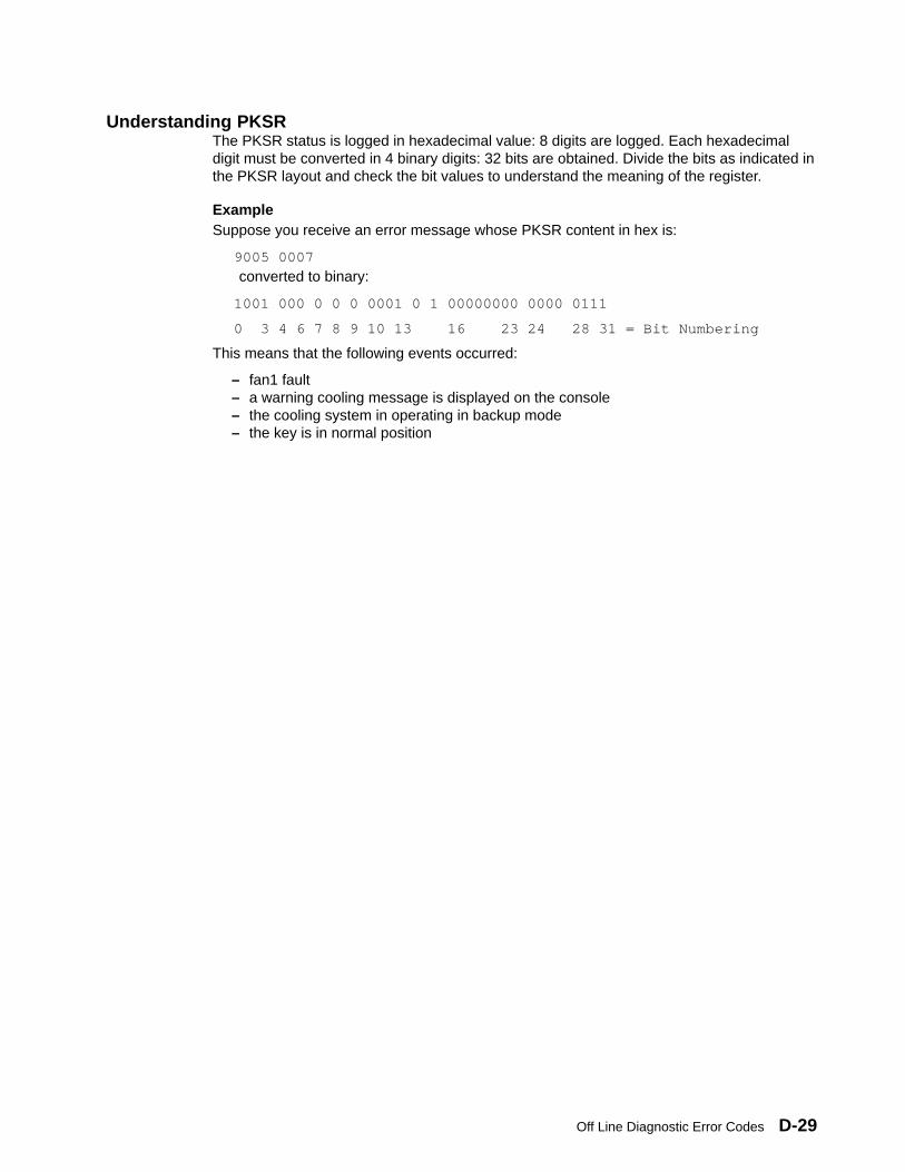
Off Line Diagnostic Error Codes D-29
Understanding PKSRThe PKSR status is logged in hexadecimal value: 8 digits are logged. Each hexadecimaldigit must be converted in 4 binary digits: 32 bits are obtained. Divide the bits as indicated inthe PKSR layout and check the bit values to understand the meaning of the register.
ExampleSuppose you receive an error message whose PKSR content in hex is:
9005 0007
converted to binary:
1001 000 0 0 0 0001 0 1 00000000 0000 0111
0 3 4 6 7 8 9 10 13 16 23 24 28 31 = Bit Numbering
This means that the following events occurred:
– fan1 fault– a warning cooling message is displayed on the console– the cooling system in operating in backup mode– the key is in normal position

Service GuideD-30
Power/Keylock Status Register Bit Definitions E-1
Appendix E. SRN 409-098 Cover Interlock Diagnosing
Because the cover interlock circuitry is routed through several boards and cables in thesystem unit, if an SRN 409-098 is received by the service representative, the followingprocedures should be performed to further diagnose the problem.
The primary purpose of the cover interlock switch is to sense when the top cover has beenlifted with main power turned on, and if this occurs the system logic turns main power off.The logic also shuts off the main power if the CPU module is not fully seated.
If the cover is opened with the main power turned on, the main power is turned off and 888103 409 098 appears on the operator panel display. If the system is already in standbymode (main power off), there may be no obvious indication on the operator panel display butthe system power will not come on.
The only way to return power to the system once the cover interlock switch has caused themain power to be turned off is to close the top cover (making sure that the cover interlockswitch is closed), then turn the system power off using the main power switch on the rear ofthe system unit, wait several seconds, and then using the main power switch on the rear ofthe system unit turn the main power on.
Further DiagnosisIf you are diagnosing a problem that causes SRN 409–098, do the following checks tofurther diagnose the problem:
Attention: Before doing the following checks, observe safety notices in the “Removal andReplacement Procedures” chapter of this book.
• Check the interlock switch. The switch may be located at the rear or the front of thesystem unit depending on when your system unit was assembled. Check the cover forcorrect fit and correct actuation of the switch. If the switch is actuating correctly, you canverify that it is functioning correctly by replacing it.
• Check the continuity of the switch through the backplane to verify the backplane:
– Remove the power supply and the CPU module. These parts must be removed toprevent false readings.

Service GuideE-2
– The interlock switch is connected to the backplane through connector P11. You cansee this with the power supply removed.
Note: In the figure below, connectors shown with dotted lines are on the rear side of theback plane, however the pins for these connectors are accessible from the front sideof the back plane.
Base Unit Back Plane(Front View)
LeftPin
RightPin
32313029
ZBD
etc.
Y01
16
87
ABCDE
etc.
Y12
6
etc.
32
3031
ZBDFetc.
Y16
The left pin of connector P11 connects to the system interface board connector Y12 pinC08. Check for continuity between these pins.
The left pin of connector P11 also connects to the power supply connector Y16 pinZ32. Check for continuity between these pins.
The right pin of connector P11 connects to the system planar board connector Y01 pinZ32. Check for continuity between these pins.
If you don’t have continuity at the points listed above, replace the backplane.Otherwise, continue below.
Check the system planar board, system interface board, power supply and backplanefor loose connections or damage. If you do not find a problem, replace the parts in theorder listed.
System Power States F-1
Appendix F. System Power States
The state of the system is dependant on the condition of four variable conditions that effecthow the system IPLs or shuts down. The four conditions are:
• the position of the Power-on button
This button has two positions. It can be pressed in to the On position (position for turningthe power on), or it can be in the out or Off position.
• the position of the system key (physical key mode or electronic key mode)
The system key represents the condition (Normal, Secure, or Service) that the system isset to by the physical key mode switch or the electronic key mode switch.
• the was_shutdown status
The system keeps a record when it has been shutdown using the shutdown –Fcommand since the last IPL.
• the power_fault status
The system keeps a record when it receives a power fault condition since the last IPL.
Power StatesThe state of the system depends on how the variables were set either when the power wasapplied to the system, or when the power was removed.
MAIN_STANDBYThis is the initial state of the system when power is first applied (by plugging a 7012 GSeries into an electrical outlet, or by setting the main power switch of the 7013 J Series tothe On position for example). When in this state, the BUMP console displays STANDBY,unless the console is set to display the operator panel display error messages.
The Power-on button and the BUMP console Enter key are polled by the systemcontinuously for a change in status. The system remains in this state until one of thefollowing occurs:
• If the Power-on button is initially detected to be in the On position, and thewas_shutdown status is false, the system goes to the WAIT_POWER_ON state.
• If the Power-on button is pressed and changes from the Off position to the On position,the system goes to the WAIT_POWER_ON state.
• If the Power-on button is pressed and changes from the On position to the Off position,the system sets the was_shutdown status to false.
• If the BUMP console Enter button is pressed, the system goes to the SBB_GATEWAYstate.
SBB_GATEWAYIn this state the > character is displayed on the BUMP console and the cursor is located twospaces to the right of the > prompt (> _).
• If the command sbb is entered on the BUMP console, and the system key is in theService position, the system goes to the SBB_MENU state.
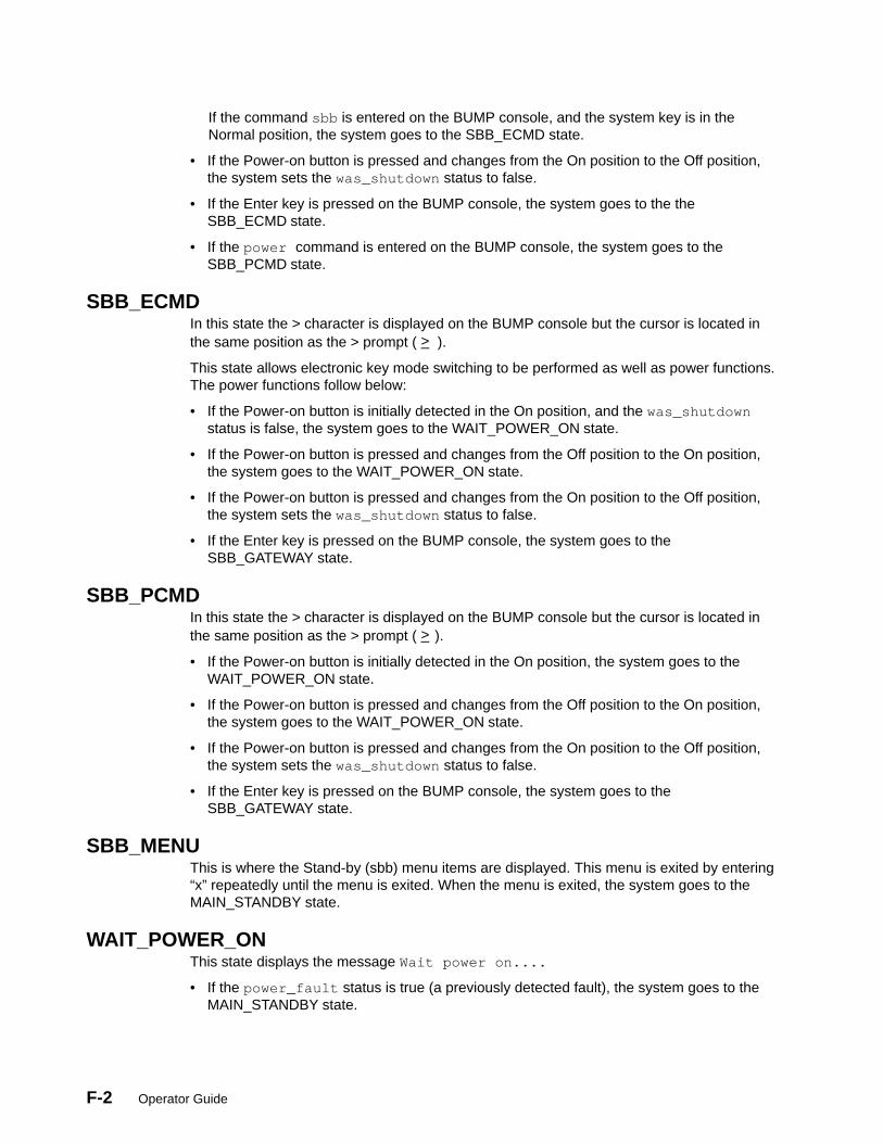
F-2 Operator Guide
If the command sbb is entered on the BUMP console, and the system key is in theNormal position, the system goes to the SBB_ECMD state.
• If the Power-on button is pressed and changes from the On position to the Off position,the system sets the was_shutdown status to false.
• If the Enter key is pressed on the BUMP console, the system goes to the theSBB_ECMD state.
• If the power command is entered on the BUMP console, the system goes to theSBB_PCMD state.
SBB_ECMDIn this state the > character is displayed on the BUMP console but the cursor is located inthe same position as the > prompt ( >_ ).
This state allows electronic key mode switching to be performed as well as power functions.The power functions follow below:
• If the Power-on button is initially detected in the On position, and the was_shutdownstatus is false, the system goes to the WAIT_POWER_ON state.
• If the Power-on button is pressed and changes from the Off position to the On position,the system goes to the WAIT_POWER_ON state.
• If the Power-on button is pressed and changes from the On position to the Off position,the system sets the was_shutdown status to false.
• If the Enter key is pressed on the BUMP console, the system goes to theSBB_GATEWAY state.
SBB_PCMDIn this state the > character is displayed on the BUMP console but the cursor is located inthe same position as the > prompt ( >_ ).
• If the Power-on button is initially detected in the On position, the system goes to theWAIT_POWER_ON state.
• If the Power-on button is pressed and changes from the Off position to the On position,the system goes to the WAIT_POWER_ON state.
• If the Power-on button is pressed and changes from the On position to the Off position,the system sets the was_shutdown status to false.
• If the Enter key is pressed on the BUMP console, the system goes to theSBB_GATEWAY state.
SBB_MENUThis is where the Stand-by (sbb) menu items are displayed. This menu is exited by entering“x” repeatedly until the menu is exited. When the menu is exited, the system goes to theMAIN_STANDBY state.
WAIT_POWER_ONThis state displays the message Wait power on....
• If the power_fault status is true (a previously detected fault), the system goes to theMAIN_STANDBY state.
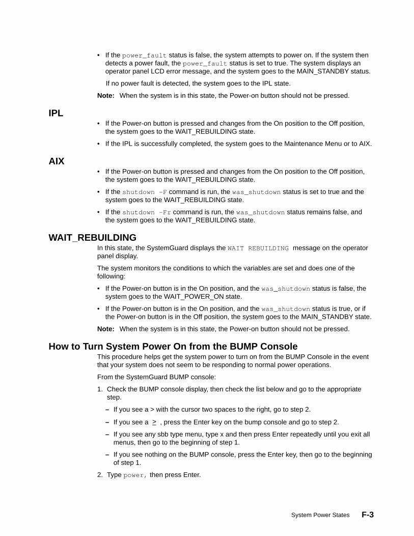
System Power States F-3
• If the power_fault status is false, the system attempts to power on. If the system thendetects a power fault, the power_fault status is set to true. The system displays anoperator panel LCD error message, and the system goes to the MAIN_STANDBY status.
If no power fault is detected, the system goes to the IPL state.
Note: When the system is in this state, the Power-on button should not be pressed.
IPL• If the Power-on button is pressed and changes from the On position to the Off position,
the system goes to the WAIT_REBUILDING state.
• If the IPL is successfully completed, the system goes to the Maintenance Menu or to AIX.
AIX• If the Power-on button is pressed and changes from the On position to the Off position,
the system goes to the WAIT_REBUILDING state.
• If the shutdown –F command is run, the was_shutdown status is set to true and thesystem goes to the WAIT_REBUILDING state.
• If the shutdown –Fr command is run, the was_shutdown status remains false, andthe system goes to the WAIT_REBUILDING state.
WAIT_REBUILDINGIn this state, the SystemGuard displays the WAIT REBUILDING message on the operatorpanel display.
The system monitors the conditions to which the variables are set and does one of thefollowing:
• If the Power-on button is in the On position, and the was_shutdown status is false, thesystem goes to the WAIT_POWER_ON state.
• If the Power-on button is in the On position, and the was_shutdown status is true, or ifthe Power-on button is in the Off position, the system goes to the MAIN_STANDBY state.
Note: When the system is in this state, the Power-on button should not be pressed.
How to Turn System Power On from the BUMP ConsoleThis procedure helps get the system power to turn on from the BUMP Console in the eventthat your system does not seem to be responding to normal power operations.
From the SystemGuard BUMP console:
1. Check the BUMP console display, then check the list below and go to the appropriatestep.
– If you see a > with the cursor two spaces to the right, go to step 2.
– If you see a >_ , press the Enter key on the bump console and go to step 2.
– If you see any sbb type menu, type x and then press Enter repeatedly until you exit allmenus, then go to the beginning of step 1.
– If you see nothing on the BUMP console, press the Enter key, then go to the beginningof step 1.
2. Type power, then press Enter.

F-4 Operator Guide
If the system power does not turn on, the Power-on button may be in the off position. Goto the system unit and press the Power-on button (only press the button once),
If the system power still does not turn on there may be an earlier fault condition. Removemain power from the system unit, wait 30 seconds, and restore main power.
The system should IPL if the Power-on button is in the On position. If the button is not inthe On position, wait until standby is displayed on the LCD then press the Power-onbutton one more time.
How to Turn System Power On Using the Power-on ButtonThis procedure helps to get the system power to turn on using the Power-on button in theevent that your system does not seem to be responding to normal power operations.
From the SystemGuard BUMP console:
1. Check the BUMP console display, then check the list below and go to the appropriatestep.
– If you see a > with the cursor two spaces to the right, press Enter on the BUMPconsole, go to the beginning of step 1.
– If you see a >_ , go to step 2.
– If you see any sbb type menu, type x and then press Enter repeatedly until until youexit all menus, then go to step 1.
– If you see nothing on the BUMP console, go to step 2.
2. Press the Power-on button to the On position (pushed in).
If the system power does not turn on, the Power-on button may have been in the onposition already, wait five seconds and press the Power-on button again.
If the system power still does not turn on there may be an earlier fault condition. Removemain power from the system unit, wait 30 seconds, and restore main power.
The system should IPL if the Power-on button is in the On position. If the button is not inthe On position, wait until standby is displayed on the LCD then press the Power-onbutton one more time.

Glossary X-1
Glossary: Special Terms Used in SystemGuard
BP (back plane) . A panel located in the systemunit and used to interconnect boards and devices.
BIST (built in self-test) . Tests performed duringthe standby phase of the IPL process. The BISTphase comes ahead of the POST phase.
BUMP (bring-up microprocessor). Amicroprocessor which monitors the system,especially during the various IPL phases beforeAIX is loaded.
C1D card . See CPU card.
CPU card . A card containing the central processorunit (CPU). CPUn is used to designate the nth CPUcard. For example, CPU2 designates the secondCPU card.
CPU (central processor unit) . A primaryprocessor for general calculations.
DIMM (dual in-line memory module). Seememory module.
Electronic Mode Switch (also known as E_KEY).A flag which enables the Key Mode Switch to bechanged without actually moving the physical key.
EEPROM (electronically erasableprogrammable read-only memory) . A type ofnon-volatile memory used to store firmwaremaintenance programs (like SSF) or bootprograms.
FEPROM (flash electronically erasableprogrammable read-only memory) . A type ofnon-volatile memory used to store firmwaremaintenance programs (like SystemGuard) or IPLprograms.
E_KEY. See Electronic Mode Switch.
ELM. See I/O planar
FFC (failing function code).
FRU (field replaceable unit).
I2C (inter integrated circuit) . Special circuits usedto connect devices to a high-speed bus called theI2C bus.
IOD. See I/O card.
I/O: Input /Output .
I/O card . A card which handles system I/O anddirectly connects to the system planar.
IPL (initial program load) . The first phase of thesystem program loading.
JTAG (join test action group).
LCD (liquid crystal display) . A low power displayscreen. There is a small LCD screen on theoperator panel.
MCA (Micro Channel adapter) . An adapter for themicro channel bus.
MCA Planar. A card with connectors for MicroChannel adapter cards.
Memory Module. A card containing one (SIMM) ortwo (DIMM) rows of memory chips.
MPE. A type of memory card.
MR2. A memory card with 8 8MB memorymodules.
MR4. A memory card with 8 32MB memorymodules.
MVR (multivoltage regulator) . A power supplyunit which regulates several voltage levels forvarious system parts (disks, CPUs, memory chips).
NFx. A type of memory card.
NVRAM (non volatile random access memory).
MP. The MCA planar located in the base unit.
MPB. See System planar.
MPe. The MCA planar located in the expansionunit.
PMA. See MP.
PME. See MPe.
POS (programmable option select). POSregisters are used to specify MCA board options.
POST (power-on self-test) . Tests performedduring the initial phase of the program loadprocess. The BIST phase comes ahead of thePOST phase.
RDS (removable disk status) . The statusinformation for a removable disk drive (a disk drive
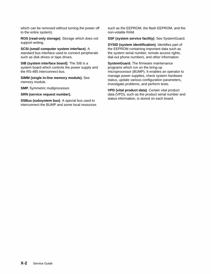
X-2 Service Guide
which can be removed without turning the power offto the entire system).
ROS (read-only storage) . Storage which does notsupport writing.
SCSI (small computer system interface) . Astandard bus interface used to connect peripheralssuch as disk drives or tape drives.
SIB (system interface board) . The SIB is asystem board which controls the power supply andthe RS-485 interconnect bus.
SIMM (single in-line memory module). Seememory module.
SMP. Symmetric multiprocessor.
SRN (service request number).
SSBus (subsystem bus) . A special bus used tointerconnect the BUMP and some local resources
such as the EEPROM, the flash EEPROM, and thenon-volatile RAM.
SSF (system service facility) . See SystemGuard.
SYSID (system identification) . Identifies part ofthe EEPROM containing important data such asthe system serial number, remote access rights,dial-out phone numbers, and other information.
SystemGuard. The firmware maintenanceprograms which run on the bring-upmicroprocessor (BUMP). It enables an operator tomanage power supplies, check system hardwarestatus, update various configuration parameters,investigate problems, and perform tests.
VPD (vital product data) . Certain vital productdata (VPD), such as the product serial number andstatus information, is stored on each board.

Index X-3
Index
AAutoserviceIPL Flag, 2-36
Bback plane
base unit, 1-5expansion unit, 1-30
base unitback plane, 1-5description, 1-1SCSI bus, 1-2SCSI controllers, 1-3SCSI terminators, 1-2
Boot Multiuser AIX in Service Flag, 2-37
BUMP Console Flag, 2-36
CC1D board. See CPU card
card cage, Micro Channel adapter, 1-3
circuit breaker (CB), 1-41
cluster power control (CPC), 1-11
configure a disk drive, 4-36
cover interlock diagnosing, E-1
CPC (cluster power control), 1-11
Customer Maintenance Password, 2-37
customer outlet, checking, 1-41
Ddata flow, 1-36
diagnosing cover interlock, E-1
Dial–Out Authorization Flag, 2-36
digital multimeter, 1-41
disk driveconfigure, 4-36location in expansion unit, 1-26unconfigure, 4-36
EElectronic Mode Switch from Service Line Flag,
2-37
error codes, off line diagnostics, D-1
error logging, PKSR register, D-26
expansion unitback plane, 1-30description, 1-24Micro Channel card cage, 1-27SCSI buses, 1-26SCSI controllers, 1-28SCSI terminators, 1-26
FFastIPL Flag, 2-36
flash EEPROM, reloading, B-7
Gground impedance, 1-41
Hhardware components
CPU module, 1-17CPU card, 1-18I/O card, 1-18memory cards, 1-19system planar, 1-17
disk drives, 1-13disk drives fan module, 1-17
fan filter, 1-15diskette drive, 1-13, 1-32main fan module
base unit, 1-14expansion unit, 1-32fan filter, 1-15
MCA card cage, 1-34MCA fan module, 1-14media devices, 1-14
1/4-inch cartridge streamer drive, 1-144mm tape drive, 1-14

X-4 Service Guide
8mm tape drive, 1-14CD-ROM drive, 1-14
Micro Channel adapters card cage, 1-34operator panel, 1-13, 1-32power supply, 1-14SCSI interface card, 1-34system interface board, 1-4, 1-22, 1-34
II/O card, 1-8
inspection, service guide, 1-42
installation checkout procedure, 1-43
interlock switch, top cover, 4-101
internal connectorsback plane
base unit, 1-5expansion unit, 1-30
I/O card, 1-8MCA planar
base unit, 1-10expansion unit, 1-29
system planar, 1-9
IOD board. See I/O card
MMaintenance Password, 2-37
MCA planarbase unit, 1-10expansion unit, 1-29
Micro Channel adapter, card cage, 1-3
model R00 rack, cluster power control (CPC), 1-11
modifying SystemGuard parameters, B-1
MP. See MCA planar; MCA planar (base unit)
MPB boardSee also system planarsee system planar, 4-80
MPe. See MCA planar; MCA planar (expansionunit)
multi processor board, see system planar, 4-80
Ooff line diagnostics, error codes, D-1
operator panel, 2-3
Ppart information
base unit internal cables, 5-10covers, 5-14CPU module, 5-6expansion unit internal cables, 5-12expansion unit rear view, 5-8front view, 5-2power cable and plug, 5-15rear view, 5-4
phase pin, 1-41
PMA. See MCA planar (base unit)
PME board. See MCA planar (expansion unit)
power cable, characteristic, 1-40
power cables, 1-40
power flow, 1-35
power statesAIX, F-3IPL, F-3MAIN_STANDBY, F-1SBB_ECMD, F-2SBB_GATEWAY, F-1SBB_MENU, F-2SBB_PCMD, F-2WAIT_POWER_ON, F-2WAIT_REBUILDING, F-3
power states, system, F-1
power-on from BUMP console, F-3
power-on using the power-on button, F-4
Rreference information, power cables, 1-40
removable disks switch, 1-22
removal and installation proceduresCPU card, 4-73I/O card, 4-73main power switch, 4-90memory cards, 4-73
removal and Replacement procedure, systemplanar, 4-80
removal and replacement procedures, 4-13.5-inch diskette drive, 4-28back plane, 4-102CPU module, 4-70disk drives, 4-40
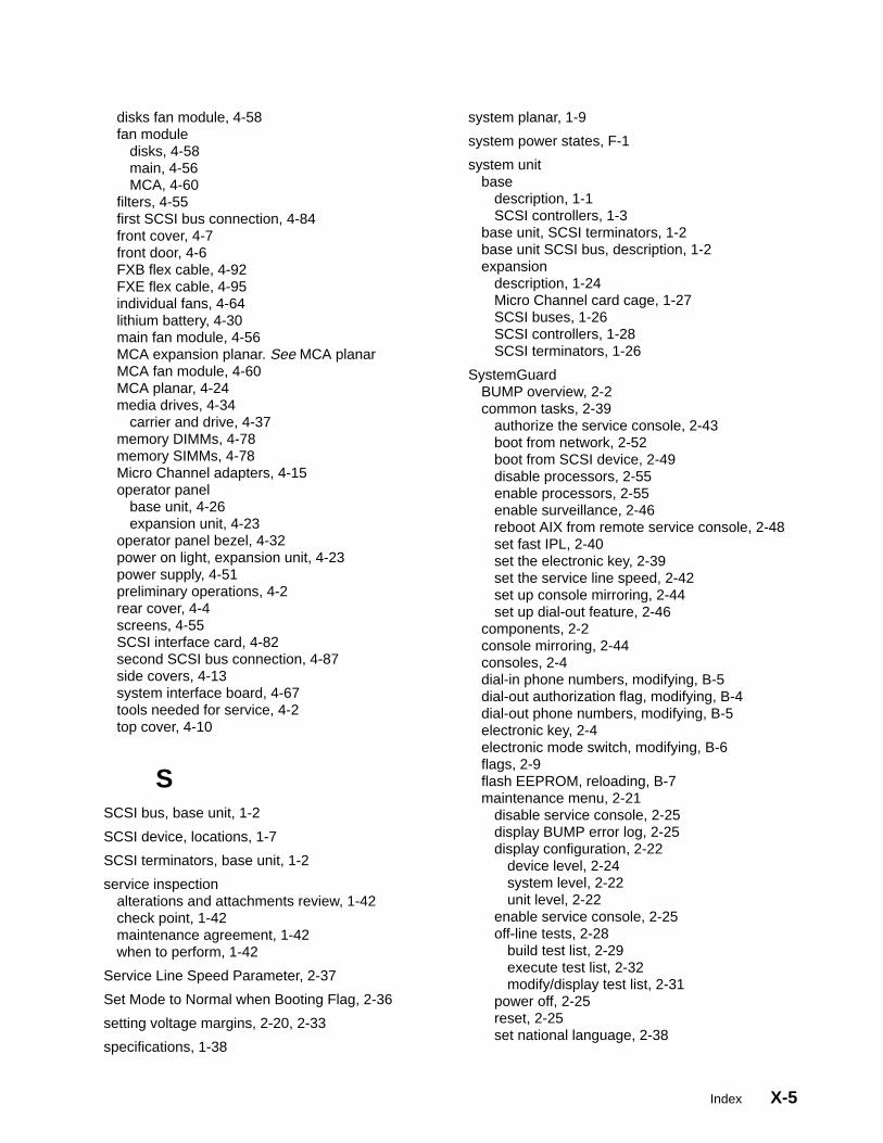
Index X-5
disks fan module, 4-58fan module
disks, 4-58main, 4-56MCA, 4-60
filters, 4-55first SCSI bus connection, 4-84front cover, 4-7front door, 4-6FXB flex cable, 4-92FXE flex cable, 4-95individual fans, 4-64lithium battery, 4-30main fan module, 4-56MCA expansion planar. See MCA planarMCA fan module, 4-60MCA planar, 4-24media drives, 4-34
carrier and drive, 4-37memory DIMMs, 4-78memory SIMMs, 4-78Micro Channel adapters, 4-15operator panel
base unit, 4-26expansion unit, 4-23
operator panel bezel, 4-32power on light, expansion unit, 4-23power supply, 4-51preliminary operations, 4-2rear cover, 4-4screens, 4-55SCSI interface card, 4-82second SCSI bus connection, 4-87side covers, 4-13system interface board, 4-67tools needed for service, 4-2top cover, 4-10
SSCSI bus, base unit, 1-2
SCSI device, locations, 1-7
SCSI terminators, base unit, 1-2
service inspectionalterations and attachments review, 1-42check point, 1-42maintenance agreement, 1-42when to perform, 1-42
Service Line Speed Parameter, 2-37
Set Mode to Normal when Booting Flag, 2-36
setting voltage margins, 2-20, 2-33
specifications, 1-38
system planar, 1-9
system power states, F-1
system unitbase
description, 1-1SCSI controllers, 1-3
base unit, SCSI terminators, 1-2base unit SCSI bus, description, 1-2expansion
description, 1-24Micro Channel card cage, 1-27SCSI buses, 1-26SCSI controllers, 1-28SCSI terminators, 1-26
SystemGuardBUMP overview, 2-2common tasks, 2-39
authorize the service console, 2-43boot from network, 2-52boot from SCSI device, 2-49disable processors, 2-55enable processors, 2-55enable surveillance, 2-46reboot AIX from remote service console, 2-48set fast IPL, 2-40set the electronic key, 2-39set the service line speed, 2-42set up console mirroring, 2-44set up dial-out feature, 2-46
components, 2-2console mirroring, 2-44consoles, 2-4dial-in phone numbers, modifying, B-5dial-out authorization flag, modifying, B-4dial-out phone numbers, modifying, B-5electronic key, 2-4electronic mode switch, modifying, B-6flags, 2-9flash EEPROM, reloading, B-7maintenance menu, 2-21
disable service console, 2-25display BUMP error log, 2-25display configuration, 2-22
device level, 2-24system level, 2-22unit level, 2-22
enable service console, 2-25off-line tests, 2-28
build test list, 2-29execute test list, 2-32modify/display test list, 2-31
power off, 2-25reset, 2-25set national language, 2-38

X-6 Service Guide
set parameters, 2-32phone numbers, 2-34power-on command parameters, 2-33set configuration, 2-34voltage margins, 2-33
system boot, 2-26menus, 2-11
maintenance menu, 2-21stand-by menu, 2-12
modem configuration, 2-47modifying service support parameters, B-1parameters, 2-9phases, 2-4
boot, 2-5init, 2-5init to AIX load and run-time, 2-9init to Boot, 2-9Maint to Boot, 2-9maintenance, 2-5run-time, 2-5stand-by, 2-4stand-by to init, 2-6
physical key, 2-4power, 2-2remote authorization flag, modifying, B-3remote operation configuration, C-1service support parameters
changing flags and parameters, B-3default values, B-1
stand-by menu, 2-12display configuration, 2-13I2C maintenance, 2-19set configuration, 2-17set flags, 2-15set unit number, 2-16SSbus maintenance, 2-18
test groups, A-1descriptions, A-3
using, 2-1working with, 2-10
SystemGuard parameters, modifying, B-1
Ttop cover, interlock switch, 4-101
Uunconfigure a disk drive, 4-36
Vvoltage margins, setting, 2-20, 2-33


Printed in the U.S.A.
SA23-2725-02
93H
6490