Service Guide - skf.com · Oil Refill Inlet Mist Outlet 1½NPT(f) Mist Pressure Gauge ... Failure...
14
Service Guide 31151-D 32301-D 31152-D 32302-D 31154-D 32304-D 31159-D 32309-D M-Series Oil Mist Generators Alemite, LLC 167 Roweland Drive, Johnson City, Tennessee 37601 www.alemite.com Copyright © 2012 by Alemite, LLC This document contains confidential information that is the property of Alemite, LLC and is not to be copied, used, or disclosed to others without express written permission. 671015 SER 31151-D Revision (6-12) Description These models of the M-Series Oil Mist Generators include: 3-Gallon (usable) powder coated reservoir Oil Level Sightglass w/ Thermometer Air Regulator and Filter Air Heater w/ Temperature Controller Mist Pressure Gauge Oil Heater w/ High Temperature Limit Switch Hi-Lo Level and Refill Warning Switches Hi-Lo Mist Pressure Switches Stack Light (audible and visible) Automatic Oil Refill (pump not included) Model Numbers provide voltage and nozzle identifi- cation: 1st digit = reservoir capacity 2nd, 3rd, & 4th digit = supply voltage 5th digit = Mist Nozzle Size 1 = 1 cfm (nominal) 2 = 2.3 cfm (nominal) 4 = 4.3 cfm (nominal) 9 = 9.7 cfm (nominal) Example: 31154-D = 3 gallon, 115V, 4.3 cfm MODEL NOZZLE OUTPUT(NOMINAL) CURRENT (NOMINAL) Amp VOLTAGE (NOMINAL) Vac cfm l/m 31151-D 1.0 28 5 120 31152-D 2.3 65 31154-D 4.3 122 31159-D 9.7 275 10 32301-D 1.0 28 3 240 32302-D 2.3 65 32304-D 4.3 122 32309-D 9.7 275 5 Figure 1 M-Series Oil Mist Generator (-D Models) Table 1 Model Identification Chart Oil Mist Lubrication System A “system” consists of a Mist Generator, mist distribu- tion (header) piping, and mist “reclassifier” fittings (to convert the oil mist into a usable state at the point of lubrication). Attention to the recommended installation practices (see pages 7 through 9) will insure the desired lubrication results. Manual Oil Refill Loader Fitting Control Box 1/4 NPT (f ) Air Inlet 1/4 NPT (f ) Moisture Separator Water Drain Drain Plug Air Heater Air Filter High Oil Temp Switch Air Regulator With Gauge Clean Out Door Automatic Oil Refill Inlet Mist Outlet 1½NPT(f ) Mist Pressure Gauge Relief Valve Alarm Stack Power-In Air Temperature Controller Sound Red Amber Green
Transcript of Service Guide - skf.com · Oil Refill Inlet Mist Outlet 1½NPT(f) Mist Pressure Gauge ... Failure...

Service Guide31151-D 32301-D31152-D 32302-D31154-D 32304-D31159-D 32309-D
M-Series Oil Mist Generators
Alemite, LLC 167 Roweland Drive, Johnson City, Tennessee 37601
www.alemite.comCopyright © 2012 by Alemite, LLC
This document contains confi dential information that is the property of Alemite, LLCand is not to be copied, used, or disclosed to others without express written permission.671015
SER 31151-DRevision (6-12)
DescriptionThese models of the M-Series Oil Mist Generators include: 3-Gallon (usable) powder coated reservoir Oil Level Sightglass w/ Thermometer Air Regulator and Filter Air Heater w/ Temperature Controller Mist Pressure Gauge Oil Heater w/ High Temperature Limit Switch Hi-Lo Level and Refi ll Warning Switches Hi-Lo Mist Pressure Switches Stack Light (audible and visible) Automatic Oil Refi ll (pump not included)Model Numbers provide voltage and nozzle identifi - cation: 1st digit = reservoir capacity 2nd, 3rd, & 4th digit = supply voltage 5th digit = Mist Nozzle Size 1 = 1 cfm (nominal) 2 = 2.3 cfm (nominal) 4 = 4.3 cfm (nominal) 9 = 9.7 cfm (nominal)Example: 31154-D = 3 gallon, 115V, 4.3 cfm
MODEL NOZZLE OUTPUT(NOMINAL) CURRENT (NOMINAL)
AmpVOLTAGE (NOMINAL)
Vaccfm l/m
31151-D 1.0 28
5120
31152-D 2.3 65
31154-D 4.3 122
31159-D 9.7 275 10
32301-D 1.0 28
3 240
32302-D 2.3 65
32304-D 4.3 122
32309-D 9.7 275 5
Figure 1 M-Series Oil Mist Generator (-D Models)
Table 1 Model Identifi cation Chart
Oil Mist Lubrication SystemA “system” consists of a Mist Generator, mist distribu-tion (header) piping, and mist “reclassifi er” fi ttings (to convert the oil mist into a usable state at the point of lubrication). Attention to the recommended installation practices (see pages 7 through 9) will insure the desired lubrication results.
Manual Oil Refill Loader Fitting
ControlBox
1/4 NPT (f )Air Inlet1/4 NPT (f )
MoistureSeparator Water
Drain
DrainPlug
AirHeater
AirFilter
High OilTemp Switch
Air RegulatorWith Gauge
Clean OutDoor
AutomaticOil Refill Inlet
MistOutlet1½NPT(f )
Mist PressureGauge
ReliefValve
AlarmStack
Power-In
AirTemperature
Controller
Sound
Red
Amber
Green

SER 31151-D M-Series Oil Mist Generators
Revision (6-12) Alemite LLC2
Figure 2 M-Series Oil Mist Generator (-D models) - exploded view
23
1
65
4 7
8
91029
28
26
271112
13
14
16
20
19
17
22 23
30
3132
24 25
15a
15b
18
21
SER 31151-DM-Series Oil Mist Generators
Revision (6-12)Alemite LLC 3
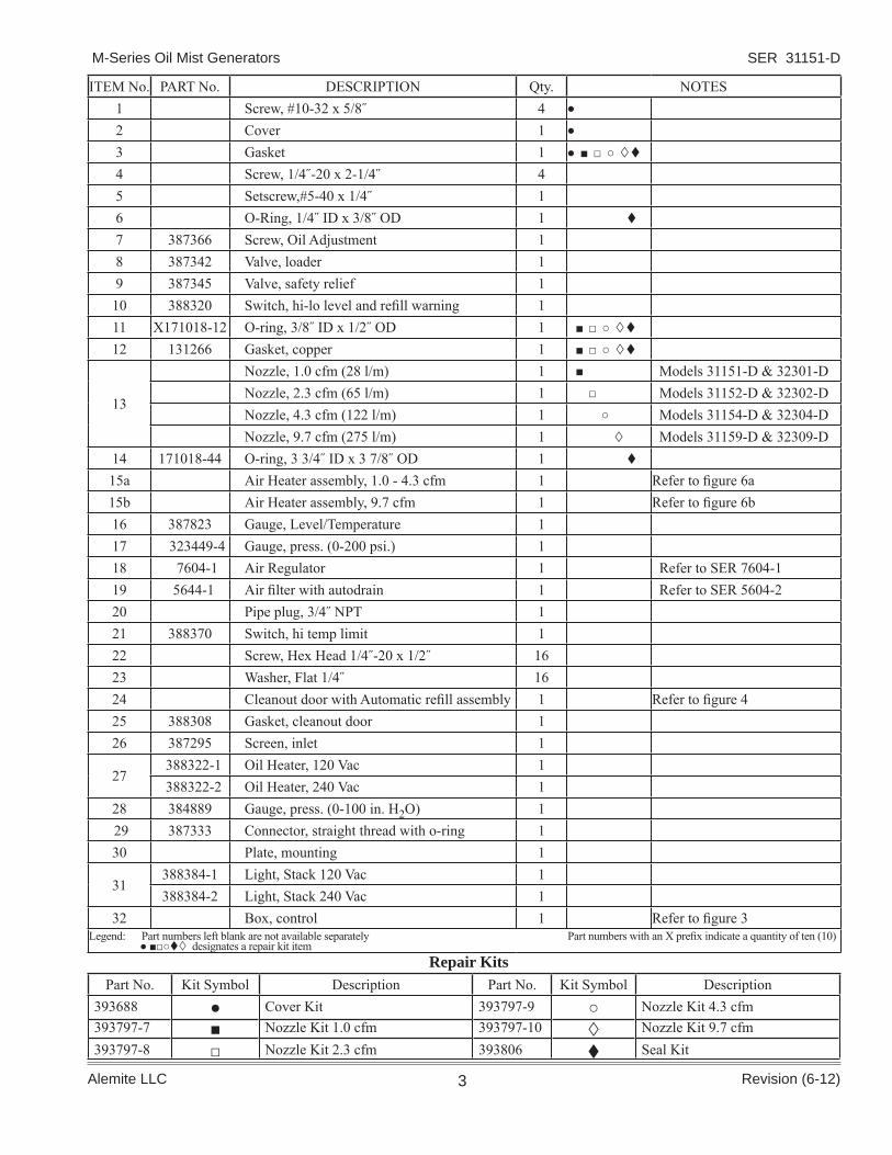
ITEM No. PART No. DESCRIPTION Qty. NOTES1 Screw, #10-32 x 5/8˝ 4 ●
2 Cover 1 ●
3 Gasket 1 ● ■ □ ○
4 Screw, 1/4˝-20 x 2-1/4˝ 45 Setscrew,#5-40 x 1/4˝ 16 O-Ring, 1/4˝ ID x 3/8˝ OD 1
7 387366 Screw, Oil Adjustment 18 387342 Valve, loader 19 387345 Valve, safety relief 110 388320 Switch, hi-lo level and refi ll warning 111 X171018-12 O-ring, 3/8˝ ID x 1/2˝ OD 1 ■ □ ○
12 131266 Gasket, copper 1 ■ □ ○
13
Nozzle, 1.0 cfm (28 l/m) 1 ■ Models 31151-D & 32301-DNozzle, 2.3 cfm (65 l/m) 1 □ Models 31152-D & 32302-DNozzle, 4.3 cfm (122 l/m) 1 ○ Models 31154-D & 32304-DNozzle, 9.7 cfm (275 l/m) 1 Models 31159-D & 32309-D
14 171018-44 O-ring, 3 3/4˝ ID x 3 7/8˝ OD 1
15a Air Heater assembly, 1.0 - 4.3 cfm 1 Refer to fi gure 6a15b Air Heater assembly, 9.7 cfm 1 Refer to fi gure 6b16 387823 Gauge, Level/Temperature 117 323449-4 Gauge, press. (0-200 psi.) 118 7604-1 Air Regulator 1 Refer to SER 7604-119 5644-1 Air fi lter with autodrain 1 Refer to SER 5604-220 Pipe plug, 3/4˝ NPT 121 388370 Switch, hi temp limit 122 Screw, Hex Head 1/4˝-20 x 1/2˝ 1623 Washer, Flat 1/4˝ 1624 Cleanout door with Automatic refi ll assembly 1 Refer to fi gure 425 388308 Gasket, cleanout door 126 387295 Screen, inlet 1
27 388322-1 Oil Heater, 120 Vac 1 388322-2 Oil Heater, 240 Vac 1
28 384889 Gauge, press. (0-100 in. H2O) 1 29 387333 Connector, straight thread with o-ring 130 Plate, mounting 1
31388384-1 Light, Stack 120 Vac 1388384-2 Light, Stack 240 Vac 1
32 Box, control 1 Refer to fi gure 3Legend: Part numbers left blank are not available separately Part numbers with an X prefi x indicate a quantity of ten (10) ● ■□○ designates a repair kit item
Part No. Kit Symbol Description Part No. Kit Symbol Description393688 ● Cover Kit 393797-9 ○ Nozzle Kit 4.3 cfm393797-7 ■ Nozzle Kit 1.0 cfm 393797-10 Nozzle Kit 9.7 cfm393797-8 □ Nozzle Kit 2.3 cfm 393806 Seal Kit
Repair Kits

SER 31151-D M-Series Oil Mist Generators
Revision (6-12) Alemite LLC4
ITEM No. PART No. DESCRIPTION Qty.
39 388315 Switch 140 338512-A Check Valve 1
41 387449 Solenoid Valve, 240 Vac 1 387449-1 Solenoid Valve, 120 Vac 1
42 338208 Filter Assembly (Refer to fi gure 5) 1
ITEM No. PART No. DESCRIPTION Qty.
33 388337 Switch, mist high pressure, 50˝-55˝ H2O 134 388336 Switch, mist low pressure, 10˝-15˝ H2O 135 388346 Relay, Programmable 136 393798-2 Fuse, 5x20mm 10A 137 393798-7 Fuse, 5x20mm 1A 138 388406 Controller, Air Temperature 1
Figure 3 Control Box Assembly - exploded view
Figure 4 Automatic Refi ll Assembly - exploded view
Figure 5 388208 Filter Assembly - exploded view
34
36
35
38
41
42
43
39
40
ITEM No. PART No. DESCRIPTION Qty.
43 332964 Element, strainer (40 microns) 1
33
37
Float must be able to lift vertically as shown. Switch is open when fl oat is up.

SER 31151-DM-Series Oil Mist Generators
Revision (6-12)Alemite LLC 5
44 47
4845
46
ITEM No.
PART No. DESCRIPTION Qty.
44 388407 Thermocouple, J Type 145 388366 Cord (1/2-20 UNF Lumburg connector) 1
46 388367-1 Air Heater 120 Vac 1 388367-2 Air Heater 240 Vac 1
ITEM No. PART No. DESCRIPTION Qty.
47 388407 Thermocouple, J Type 1
48 388368-1 Air Heater 120 Vac 1 388368-2 Air Heater 240 Vac 1
Figure 6a Air Heater Assembly, 1.0-4.3 cfm Figure 6b Air Heater Assembly, 9.7 cfm

SER 31151-D M-Series Oil Mist Generators
Revision (6-12) Alemite LLC6
Specifi cationsElectrical Ratings: Voltage: See Table 1. Phase: 1 ph. Frequency: 60 Hz. Dimensions: 47˝(119.4 cm) H x 26˝(66 cm) W x 11˝(28 cm) D Reservoir: Useful Oil Capacity: 3 gallons (11.4 liters) Material: Carbon Steel Finish: Powder Coated (color RAL7016)Air Supply: Pressure (min/max): 35/150 psi (2.5/10.5 kg/cm2) Inlet Port Size1/4 NPT (f) Air Filter Media: 40 microns Air Heater For Units with 1.0 - 4.3 cfm Capacity Air Flow Rate: 7 CFM max. Power: 200 Watts Voltage: 120 Vac or 240 Vac Air Inlet: 1/8 NPT(f) Air Outlet: 1/4 NPT(f)Air Heater For Units with 9.7 cfm Capacity Air Flow Rate: 65 CFM max. Power: 500 Watts Voltage: 120 Vac or 240 Vac Air Inlet: 1/2 NPT(f) Air Outlet: 1/2 NPT(f)Safety Relief Valve Pressure: 10 psi (0.7 Bar)Oil Mist Generation Capacity: See Table 1Oil Mist Outlet Port: 1 1/2 NPT (f)Oil Heater: Power: 165 Watts Watt Density: 10 Watt/in2 max. Voltage: 120 Vac or 240 Vac Temperature Control: Integrated Thermostat Thermostat Setting: 105°F (41°C)(non-adjustable)High Oil Temperature Switch: Setting: 140°F (60°C)(non-adjustable) Switch Type: SPDT Process Port Size: ½ NPT Hi-Lo Level and Refi ll Warning Float Switches: Voltage Rating: 120/240Vac Power: 50VA max. Switch type: Top mounted, (3x) SPST Process Port Size: ⅛ NPTMist Pressure Switches Electrical Rating: 15A, 125/250 Vac High Pressure Setting: 50˝-55˝ H2O Low Pressure Setting: 10˝-15˝ H2OStack Light: Voltage: 120 Vac or 240 Vac Audible Module: 80 DB intermittent Visible Modules: Red: fl ashing Amber: fl ashing Green: continous
Figure 7 Mounting hole pattern
General Safety• Read all instructions carefully and thoroughly
before operating, maintaining or servicing the unit.
• Be sure that electrical power supply conforms to the power requirement of the unit. Refer to “Specifi cations”.
• Do not exceed pressure rating of system compo-nents.
• Do not make system components adjustments that are not recommended in this service sheet. When in doubt, consult Alemite service representatives or personal familiar with instrumentation.
• Electrical service must be performed by an elec-trician or personnel familiar with instrumentation.
• Shut off electrical power and air supply to the unit before doing service on the unit.
• Protect air lines from damage or puncture, making certain that connections are secure.
Air Inlet1/4 NPT (f)
Use 1/2” Bolts
26”(66 cm)
24”(61 cm)
28”(71.1 cm)
30”(76.2 cm)
47”(119.4 cm)
10”(25.4 cm)
SER 31151-DM-Series Oil Mist Generators
Revision (6-12)Alemite LLC 7
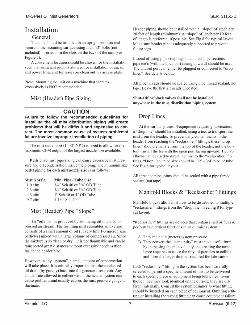
CAUTIONFailure to follow the recommended guidelines for installing the oil mist distribution piping will create problems that will be diffi cult and expensive to cor-rect. The most common cause of system problems/failure involve improper installation of piping.
The mist outlet port (1-1/2˝ NPT) is sized to allow for the maximum CFM output of the largest nozzle size available.
Restrictive mist pipe sizing can cause excessive mist pres-sure and oil condensation inside the piping. The minimum size outlet piping for each mist nozzle size is as follows:
Mist Nozzle Min. Pipe / Tube Size 1.0 cfm 3/4˝ Sch 40 or 3/4˝ OD Tube 2.3 cfm 3/4˝ Sch 40 or 3/4˝ OD Tube 4.3 cfm 1˝ Sch 40 or 1˝ OD Tube 9.7 cfm 1-1/4˝ Sch 40
Mist (Header) Pipe “Slope”
The “oil mist” is produced by atomizing oil into a com-pressed air stream. The resulting mist resembles smoke and consists of a small amount of oil (in very tiny 1-3 micron size particles) mixed with a large volume of compressed air. Since the mixture is so “lean or dry”, it is not fl ammable and can be transported great distances without excessive condensation inside the header pipe.
However, in any “system”, a small amount of condensation will take place. It is critically important that the condensed oil drain (by gravity) back into the generator reservoir. Any condensate allowed to collect within the header system can cause problems and usually causes the mist pressure gauge to fl uctuate.
Header piping should be installed with a “slope” of 1inch per 20 feet of length (minimum). A “slope” of 1inch per 10 feet of length is preferred, if possible. See Fig 8 for typical layout. Make sure header pipe is adequately supported to prevent future sags.
Instead of using pipe couplings to connect pipe sections, pipe tee’s (with the open port facing upward) should be used. The unused port can either be plugged or connected to “drop lines”. See details below.
All pipe threads should be sealed using pipe thread sealant, not tape. Leave the fi rst 2 threads uncoated.
Shut-Off or block valves shall not be installedanywhere in the mist distribution piping system.
Drop Lines
At the various pieces of equipment requiring lubrication, a “drop line” should be installed, using a tee, to transport the mist from the header. To prevent any contaminants in the header from reaching the “reclassifi er” fi ttings, these “drop lines” should emanate from the top of the header, not the bot-tom. Install the tee with the open port facing upward. Two 90o elbows can be used to direct the mist to the “reclassifi er” fi t-tings. “Drop line” pipe size should be 1/2˝ - 3/4˝ pipe or tube. See Fig 8 for typical layout.
All threaded pipe joints should be sealed with a pipe thread sealant (not tape).
Manifold Blocks & “Reclassifi er” Fittings
Manifold blocks allow mist fl ow to be distributed to multiple “reclassifi er” fi ttings from the “drop line”. See Fig 8 for typi-cal layout.
“Reclassifi er” fi ttings are devices that contain small orifi ces & perform two critical functions in an oil mist system:
A. They maintain (meter) system pressure B. They convert the “lean or dry” mist into a useful form
by increasing the mist velocity and creating the turbu-lence required to cause the tiny oil particles to collide and form the larger droplets required for lubrication.
Each “reclassifi er” fi tting in the system has been carefully selected to permit a specifi c amount of mist to be delivered to each specifi c piece of equipment being lubricated. Even though they may look identical on the outside, they are dif-ferent internally. Consult the system designer as what fi tting should be installed on each piece of equipment. Omitting a fi t-ting or installing the wrong fi tting can cause equipment failure.
Installation General
The unit should be installed in an upright position and secure to the mounting surface using four 1/2˝ bolts (not included) inserted thru the slots on the back of the unit (see Figure 7).
A convenient location should be chosen for the installation such that suffi cient room is allowed for installation of air, oil, and power lines and for reservoir clean out via access plate.
Note: Mounting the unit on a machine that vibratesexcessively is NOT recommended.
Mist (Header) Pipe Sizing

SER 31151-D M-Series Oil Mist Generators
Revision (6-12) Alemite LLC8
Vents and Drain
Successful lubrication of a ball or roller bearing in an enclosed housing requires a continuous fl ow of mist into and out of the housing. The mist fl ow cannot be “dead-headed”. For this reason, both a vent and a drain must be provided. The vent will assure continuous fl ow, while the drain will remove any nonconsumed oil that condenses in the bearing housing. See Fig 9 for typical methods of providing both vent and drain with one connection.
BearingHousing
Ventto
Atmosphere
BearingHousing
Sightglass
Snap Valve
Figure 8 Typical Installation
Figure 9 Vent & Drain
Air SupplyClean, dry, regulated compressed air is required to operate an oil mist generator. Instrument-quality air is required.
A fi lter with automatic water drain (19) and a pressure regulator (18) are included with this oil mist generator.
The end-user should install an air shut-off valve prior to the fi lter (19) to isolate the generator when maintenance operations are performed. An air solenoid valve (not supplied) can be installed upstream of the shut-off valve if synchronization with machinery operation is desired.
All pipe threads should be sealed using pipe thread sealant, not tape. Leave the fi rst 2 threads uncoated.
Typical Installation
1 inch(2.5 cm) Pipe Slope
Distribution Header
"Drop" Line
"Drain Leg"(If req'd)
Manifold Block
Sightglass &Drain Valve
10 feet (3 m)
SER 31151-DM-Series Oil Mist Generators
Revision (6-12)Alemite LLC 9
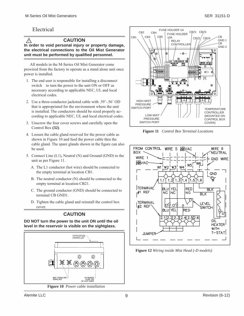
Electrical
CAUTIONIn order to void personal injury or property damage, the electrical connections to the Oil Mist Generator unit must be performed by qualifi ed personnel.
All models in the M-Series Oil Mist Generator come prewired from the factory to operate as a stand alone unit once power is installed.
1. The end user is responsible for installing a disconnect switch to turn the power to the unit ON or OFF as necessary according to applicable NEC, UL and local electrical codes.
2. Use a three-conductor jacketed cable with .39˝-.56˝ OD that is appropriated for the environment where the unit is installed. The conductors should be sized properly ac-cording to applicable NEC, UL and local electrical codes.
3. Unscrew the four cover screws and carefully open the Control Box (32).
4. Loosen the cable gland reserved for the power cable as shown in Figure 10 and feed the power cable thru the cable gland. The spare glands shown in the fi gure can also be used.
5. Connect Line (L1), Neutral (N) and Ground (GND) to the unit as per Figure 11.
A. The L1 conductor (hot wire) should be connected to the empty terminal at location CB1.
B. The neutral conductor (N) should be connected to the empty terminal at location CB21.
C. The ground conductor (GND) should be connected to terminal CB GND1.
D. Tighten the cable gland and reinstall the control box cover.
CAUTION DO NOT turn the power to the unit ON until the oil level in the reservoir is visible on the sightglass.
!
Figure 11 Control Box Terminal Locations
Figure 10 Power cable installation
Figure 12 Wiring inside Mist Head (-D models)
CB1RELAY CONTROLLER
TEMPERATURE CONTROLLER(MOUNTED ON CONTROL BOX COVER)
CB2CB3
CB4CB5
FUSE HOLDER 1AFUSE HOLDER 10A
CB21
CB22
CB23
CB24 CBGND 1CBGND 2
HIGH MISTPRESSURE
SWITCH PORT
LOW MISTPRESSURE
SWITCH PORT

SER 31151-D M-Series Oil Mist Generators
Revision (6-12) Alemite LLC10
Figure 13 Wiring Diagram (-D models)
#18 AWG600VRED
AC
LOW MIST PRESSURE SWITCH
HIGH MIST PRESSURE SWITCH
CB 21
NEUTRAL (N)BY CUSTOMER
120/240 VAC (L1)BY CUSTOMER
#18 AWG600VRED
WIRE #6
#18 AWG600V RED
#18 AWG600VRED
WIRE #4
WIRE #3
INSIDE MIST HEAD ASSY.
CB 2
BLK
CB 24
CB 22
WIRE #1
CB 23
#18 AWG600V RED
#18 AWG600VRED
AUTOMATIC REFILL ASSY.
Low OilLevel Switch
MH1.4
SEE MIST HEAD ASSY.SEE MIST HEAD ASSY.
SEE MIST HEAD ASSY.
SEE MIST HEAD ASSY.
HiGH OilLevel Switch
MH1.2
WIRE #2
TEMP CONTROL #18 AGW
RED600V
CB GND
2
INSIDE
GROUND SCREW
MIST HEAD ASSY.
YELLOW - GREEN
BLK
WHT
HIGH OIL TEMPSWITCH
L N
I1 I2 I3 I4 I5 I6 I7
Q1 Q2 Q3 Q4
I8
#18 AW G600V WHT
Oil HeaterMH 1.5
MH 1.6
WIRE #5
#18 AWG600V RED
#18 AWG600V RED
#18 AWG600V RED
BLK (9.7 cfm)OR
RED/BLK (1.0-4.3 cfm)
WHT (9.7 cfm)OR
RED/WHT (1.0-4.3 cfm)
WIRE #1
WIRE #2
WIRE #3
WIRE #6
Amb SL2
SL1
STACK LIGHT ASSY.
SL3
RED
SL4
Alarm
RED WIREJUMPER
SL0
CB 5
AUTOMATICREFILLSWITCH
DEVICE EXTERNAL TO CONTROL BOX
REFILL SOLENOID
BLK RED RED
GRNGRN
WHT WHT
GND WIRE
GND BY CUSTOMER
CB GND
1
JUMPER(VIA DIN RAIL)
#18 AWG600V RED
#18 AWG600V RED
CONTROL RELAY
Oil Refill LevelWarning Switch
MH 1.3
YEL
MH 1.1
INSIDE MIST HEAD ASSY.
CB 4
BACK OF AIRTEMPERATURECONTROLLER
#18 AWG600V WHT
HIGH AIR TEMP#18 AGW
RED600V
1
2
3
4
5
6
7
8
9
10
11
12
13
14
15
WHT
REDAIR HEATER
THERMOCOUPLE
#18 AWG600V REDJUMPERS
LOW AIR TEMP#18 AGW
RED600V
FUSE(1A)
CB 3
#18 AWG 600V RED
JUMPER
JUMPER
JUMPER
JUMPER
JUMPER
JUMPER
COM
COM
NO
NC
AIR HEATER
GREEN
S LX
MH X.X
C B XX
WIR E T E R MINAL # XXIN T HE C ONT R OL B OX
W IR E T E R MINAL # XIN T HE S T AC K LIG HT
WIR E T E R MINAL # X .XIN T HE MIS T HE AD
LE G E ND
REDBLUE
FUSE(10A)
CB 1
GRN
SER 31151-DM-Series Oil Mist Generators
Revision (6-12)Alemite LLC 11
until no tension is felt.
2. Open the air supply valve (not part of the Oil Mist Generator).
3. Turn the power ON. The red light on the Stack Light (31) should start fl ashing as no air should be fl owing and the mist pressure is below the minimum value.
4. Adjust the air pressure regulator such that the Mist Pressure Gauge (28) shows 20˝ H2O. If the system has been correctly sized and installed, the regulated air Pressure Gauge (17) should show between 25 and 40 psi depending on the generator capacity (CFM). The red light should turn off and the green light should turn on. If this is not the case, consult the trouble-shooting section.
Adjusting Oil DensityThe mist head includes an Oil Adjustment Screw (7). This screw has been adjusted at the factory to provide optimum oil density without requiring further adjustments by the user. If the screw has been removed for cleaning or o-ring replacement, it should be re-installed to the factory setting, which is one revolution out (counter-clockwise) from the lightly seated position. Deviating from the factory setting should only be done after consultation with Alemite Technical Service.
Air TemperatureWhen the mist pressure is above 10 in H2O, the air heater turns ON and the air temperature starts to rise. A digital air temperature controller is located on the upper right corner of the control box. The air temperature set point value (SV) is displayed in green to the bottom of the temperature controller screen (factory set air temperature SV is 105 °F). The current air temperature (PV) is displayed in red directly above SV. A small red light to the right of PV shows the unit of measurement (i.e. °F or °C).
OperationCAUTION
Do not operate unit without fi lling the reservoir with oil or damage may occur.
Mist OilOnly oils branded as “mist oil” should be used. Use of other oils may result in no mist generation, poor mist quality, and/or lubrication failure. Many oil blends, including common motor oils, contain anti-foaming agents which will prevent successful mist generation.
All major lubricant suppliers market “mist oil” in a variety of viscosities and in both mineral & synthetic blends. They are specifi cally formulated to atomize easily and to maximize the reclassifying at the point of lubrication. Contact your local oil supplier or Alemite for recommendations.
Only very clean oil must be added to the reservoir. For this reason, this unit has been equipped with an automatic oil refi ll located on the oil reservoir cleanout door (see Figure 1).
Filling the ReservoirIn order to automatically fi ll the reservoir, the system
should be connected to an oil refi ll pump system with a 1:1 pump ratio that provides 65 to 80 psi of oil inlet pressure. The pump must be connected the oil fi lter inlet port on the auto-matic refi ll assembly. A refi ll pump package 388415 is avail-able for this purpose. Contact your Alemite vendor for details.
The oil reservoir can also be fi lled manually through the loader fi tting located on the front face of the mist head (see Figure 1). It is designed to be used with an Alemite manual refi ll pump (P/N 388034) which includes 7 feet of hose, a 40-micron reusable fi lter element, and a loader coupler (mates with loader fi tting).
While manually fi lling the reservoir, be mindful that the actual oil level may be higher than what is visible in the sight glass. When the level is about 2 gallons as indicated on the sight glass, stop fi lling and allow some time for the level in the sight glass to stop rising, then resume fi lling until the level in the sight glass is at (or just below) the 3-gallon mark.
CAUTION Maintaining the air gap between the 3-gallon mark and the top of the tank is very important for the production of oil mist and the system’s optimal operation. If the fi nal oil level is above the 3-gallons mark, oil must be drained from the tank.
Adjusting Mist Pressure
1. Close the Air Regulator (18) by unscrewing the T-handle
SER 31151-D M-Series Oil Mist Generators
Revision (6-12) Alemite LLC12
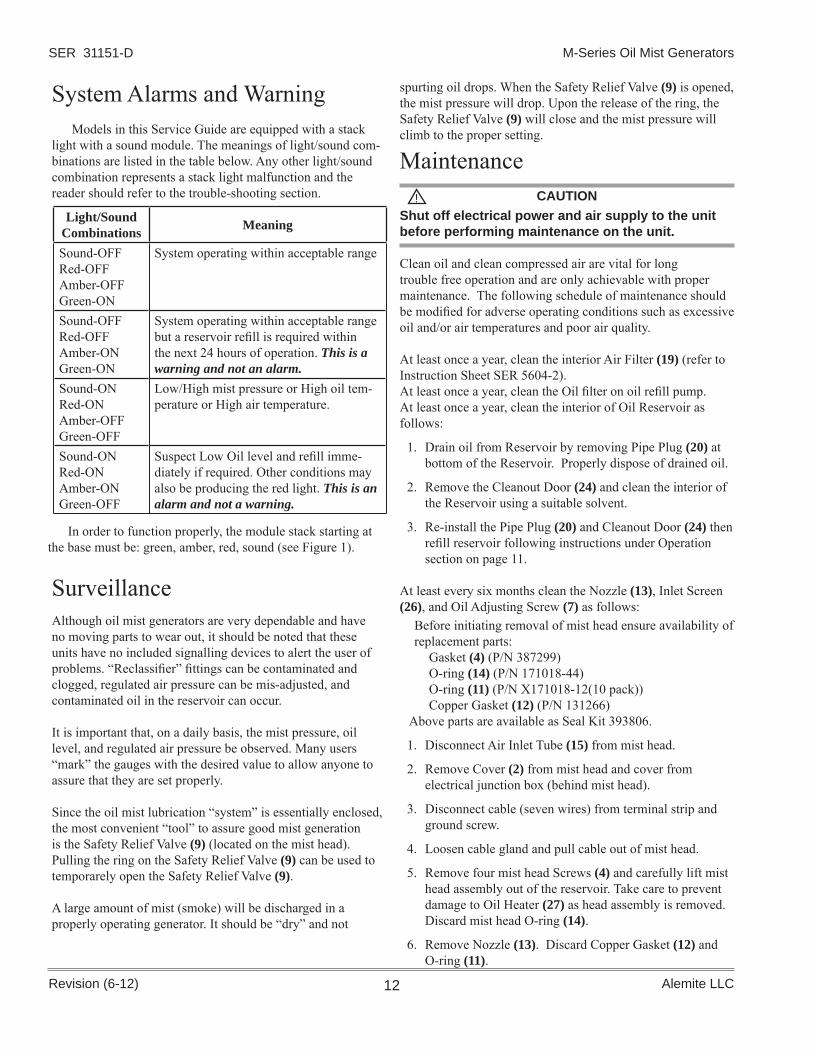
System Alarms and WarningModels in this Service Guide are equipped with a stack
light with a sound module. The meanings of light/sound com-binations are listed in the table below. Any other light/sound combination represents a stack light malfunction and the reader should refer to the trouble-shooting section.
Light/Sound Combinations Meaning
Sound-OFFRed-OFFAmber-OFFGreen-ON
System operating within acceptable range
Sound-OFFRed-OFFAmber-ONGreen-ON
System operating within acceptable range but a reservoir refi ll is required within the next 24 hours of operation. This is a warning and not an alarm.
Sound-ONRed-ONAmber-OFFGreen-OFF
Low/High mist pressure or High oil tem-perature or High air temperature.
Sound-ONRed-ONAmber-ONGreen-OFF
Suspect Low Oil level and refi ll imme-diately if required. Other conditions may also be producing the red light. This is an alarm and not a warning.
SurveillanceAlthough oil mist generators are very dependable and have no moving parts to wear out, it should be noted that these units have no included signalling devices to alert the user of problems. “Reclassifi er” fi ttings can be contaminated and clogged, regulated air pressure can be mis-adjusted, and contaminated oil in the reservoir can occur.
It is important that, on a daily basis, the mist pressure, oil level, and regulated air pressure be observed. Many users “mark” the gauges with the desired value to allow anyone to assure that they are set properly.
Since the oil mist lubrication “system” is essentially enclosed, the most convenient “tool” to assure good mist generation is the Safety Relief Valve (9) (located on the mist head). Pulling the ring on the Safety Relief Valve (9) can be used to temporarely open the Safety Relief Valve (9).
A large amount of mist (smoke) will be discharged in a properly operating generator. It should be “dry” and not
Shut off electrical power and air supply to the unit before performing maintenance on the unit.
Clean oil and clean compressed air are vital for long trouble free operation and are only achievable with proper maintenance. The following schedule of maintenance should be modifi ed for adverse operating conditions such as excessive oil and/or air temperatures and poor air quality.
At least once a year, clean the interior Air Filter (19) (refer to Instruction Sheet SER 5604-2).At least once a year, clean the Oil fi lter on oil refi ll pump.At least once a year, clean the interior of Oil Reservoir as follows:
1. Drain oil from Reservoir by removing Pipe Plug (20) at bottom of the Reservoir. Properly dispose of drained oil.
2. Remove the Cleanout Door (24) and clean the interior of the Reservoir using a suitable solvent.
3. Re-install the Pipe Plug (20) and Cleanout Door (24) then refi ll reservoir following instructions under Operation section on page 11.
At least every six months clean the Nozzle (13), Inlet Screen (26), and Oil Adjusting Screw (7) as follows:
Before initiating removal of mist head ensure availability of replacement parts:
Gasket (4) (P/N 387299) O-ring (14) (P/N 171018-44)O-ring (11) (P/N X171018-12(10 pack))Copper Gasket (12) (P/N 131266)
Above parts are available as Seal Kit 393806.
1. Disconnect Air Inlet Tube (15) from mist head.
2. Remove Cover (2) from mist head and cover from electrical junction box (behind mist head).
3. Disconnect cable (seven wires) from terminal strip and ground screw.
4. Loosen cable gland and pull cable out of mist head.
5. Remove four mist head Screws (4) and carefully lift mist head assembly out of the reservoir. Take care to prevent damage to Oil Heater (27) as head assembly is removed. Discard mist head O-ring (14).
6. Remove Nozzle (13). Discard Copper Gasket (12) and O-ring (11).
spurting oil drops. When the Safety Relief Valve (9) is opened, the mist pressure will drop. Upon the release of the ring, the Safety Relief Valve (9) will close and the mist pressure will climb to the proper setting.
MaintenanceCAUTION !
In order to function properly, the module stack starting at the base must be: green, amber, red, sound (see Figure 1).

SER 31151-DM-Series Oil Mist Generators
Revision (6-12)Alemite LLC 13
Figure 14 Mist Nozzle Assembly
VenturiHoles“O”-Ring
Crush Gasketseats here
Baffle
Threads
Oil Inlet
7. Remove Inlet Screen (26).
8. Loosen Setscrew (5) and remove Oil Adjustment Screw (7).
9. Clean the Nozzle (13) (oil inlet bore at top of nozzle and angled venturi holes just above nozzle threads as shown in fi gure 14), the Inlet Screen (26), the Oil Adjustment Screw (7), and its seat in the Mist Head using a suitable solvent.
10. Re-install the Nozzle (13) with new O-ring (11) (lubricate with oil before assembly) and Copper Gasket (12). Take care to prevent damage to O-ring (11) as it is installed on the Nozzle (13) neck and as the Nozzle (13) is installed in the mist head. The integrity of both “O”-ring (11) (which seals the vacuum to pull oil up the pick-up tube) and the Copper Gasket (12) (which seals regulated air pressure) is absolutely vital to successful mist generation. The Nozzle (13) must be tightened fi rmly to properly compress the Copper Gasket (12). Failure to do so will prevent proper mist generation.
11. Re-install the Inlet Screen (26). Do not use thread sealant.
12. Re-install Oil Adjustment Screw (7) with new O-ring (6) (lubricate with oil before assembly) by gently turning clockwise until it stops, then backing out one revolution. Tighten Setscrew (5) to lock Oil Adjustment Screw (7)
13. Before re-installing mist head assembly into reservoir bench-test as follows:
a. Obtain a clean container and fi ll with mist oil to a suffi cient level to completely cover the the oil Inlet Screen (26).
b. Make a temporary air connection to the air inlet of the mist head.
c. Immerse the oil inlet tube into the container and make sure Inlet Screen (26) is completely submerged.
d. Apply air. Within a few seconds, a signifi cant amount of mist should be generated through the holes in the baffl e at the bottom of the Nozzle (13). This will assure that the Nozzle (13) O-ring (11) is undamaged and the Copper Gasket (12) has been properly compressed.
14. Re-install mist head assembly with a new mist head O-ring (14) by reversing steps 1-5 and making sure all connections are tight.
Service1. Air Regulator 7604-1: Refer to Instruction Sheet SER 7604-12. Air Filter 5644-1: Refer to Instruction Sheet SER 5604-23. Stack Light 388384-1-2: Replacement modules are available from: C3 Controls Beaver, PA Tel: 724-775-7926 www.c3controls.com
Trouble-ShootingSpecial Note: There is a direct correlation between mist pressure and regulated air pressure. Increasing the regulated air pressure will increase the mist pressure. Mist pressure is measured in inches of water column (i.e., 20˝ H2O), while regulated air pressure is measured in PSIG. Most “systems” are designed to operate successfully at 20˝ H2O mist pressure. Operating at higher mist pressures will result in increased oil consumption.
Depending upon the system design and the number of “re-classifi er” fi ttings installed, to achieve 20˝ H2O will require a regulated air pressure of 20-45 psig. The key value is the mist pressure, not the regulated air pressure. The actual regulated air pressure to achieve 20˝ H2O should be noted and recorded. High or Low mist pressure conditions will be based upon the mist pressure reading with the regulated air pressure un-changed from what was originally recorded.
Changes Since Last PrintingInitial release

SER 31151-D M-Series Oil Mist Generators
Revision (6-12) Alemite LLC14
Condition Probable Cause RemedyHigh Mist Pressure 1. “reclassifi er” fi ttings clogged or plugged
2. Oil condensate “trapped” in distribution piping3. Regulated air supply has been mis-adjusted
1. Clean or replace “reclassifi er fi ttings”2. Remove “sags”3. Correct to recorded value
Extremely High Mist Pres-sure(Relief valve opens)
1. Failure of Crush Gasket (12) to seal Nozzle (13) to mist head2. Severe or total blockage in distribution piping
1. Remove mist head assembly from reser-voir and tighten/replace Copper Gasket (12)
2. Remove blockageFluctuating Mist Pressure Oil condensate “trapped” in distribution piping Remove “sags”Low Mist Pressure 1. Open line/valves or leaks in the distribution
piping2. Additional “reclassifi ers” installed in system
3. Mist head passages plugged4. Oil Inlet Screen (26) clogged5. Air fi lter element clogged6. Closed air supply line
1. Close valves or fi x leaks
2. Adjust regulated air pressure to achieve 20˝ H2O
3. Disassemble and clean4. Dissassemble and clean5. Replace6. Open air supply line
Lubricated Component Temperature too high
1. Distribution line obstruction2. Incorrect Oil Adjustment Screw (7) setting3. Reservoir overfi lled4. Foreign material in Inlet Screen (26)5. Foreign material in distribution vent line(s)6. Air pressure setting too low7. Foreign material in “reclassifi er” fi tting(s)8. Oil temperature too low9. Improper oil or incompatible oils10. Vacuum leaks
a. Damaged Copper Gasket (12) and/or O-Ring (11)b. Damaged Oil Adjustment Screw O-Ring (6)c. Initial tightening of Oil Pickup Tube not
suffi cient
1. Remove low spots in distribution line2. Set Oil Adjustment Screw (7)3. Drain oil until the full mark is reached
on the reservoir4. Clean or replace Inlet Screen (26)5. Clean distribution vent line(s)6. Increase air pressure7. Clean or replace “reclassifi er” fi tting(s)8. Replace Oil Heater (27) 9. Check with supplier on oils specifi c for
aerosol lubrication10.
a. Replace Copper Gasket (12) and/or O-Ring (11)
b. Replace Oil Adjustment Screw O-Ring (6)
c. Tighten Oil Pickup Tube into HeadRed light – No sound 1. Disconnected sound module
2. Incorrect module arrangement3. Defective module
1. Turn the sound module clockwise gently until it comes to a stop.
2. Ensure that starting at the base, the mod-ule arrangement is: green, amber and red with the sound module at the top.
3. Replace module.Sound – No red light 1. Disconnected red light module
2. Incorrect module arrangement3. Defective module
1. Turn the red light module clockwise gently until it comes to a stop.
2. Ensure that starting at the base, the mod-ule arrangement is: green, amber and red with the sound module at the top
3. Replace module. Sound – Light other than red
1. Incorrect module arrangement 1. Ensure that starting at the base, the mod-ule arrangement is: green, amber and red with the sound module at the top.