Service Experience - Marine...
20
Service Experience Small Bore Four-stroke Engines
Transcript of Service Experience - Marine...

Service ExperienceSmall Bore Four-stroke Engines


Contents
Introduction..................................................................................................5
Cylinder.incidents.–.L16/24.units...................................................................5
Exhaust.gas.temperature.–.L16/24................................................................6
Valve.adjustment.procedure.–.L16/24,.L21/31,.L27/38..................................7
Excessive.wear.on.valve.–.L21/31.and.L27/38...............................................7
Cavitation.–.L21/31.and.L27/38....................................................................7
Pressure.fluctuations.in.the.fuel.system.–.L21/31.and.L27/38........................8
Exhaust.gas.sensors.–.L21/31......................................................................8
Cracked.piston.–.L23/30...............................................................................9
Oval/cracked.connecting.rod.–.L23/30.and.L28/32..................................... 10
Broken.gear.wheel.–.9L27/38...................................................................... 11
Liner.and.ring.groove.wear.–.L27/38........................................................... 12
Bush.for.cam.follower.–.V28/32S................................................................ 12
Prolonged.Service.Interval.L23/30............................................................... 14
New.roller.on.valve.cam.–.L28/32H............................................................. 15
HFO.service.experience.............................................................................. 16
Leak.oil....................................................................................................... 17
Conclusion.................................................................................................. 17


5Service.Experience.–.Small.Bore.Four-stroke.Engines
Service ExperienceSmall Bore Four-stroke Engines
Introduction
For.the.small.bore.four-stroke.engines,.
considerable. know-how. is. available. in.
Denmark.within. the. four-stroke.organi-
sation.at.Holeby..The.MAN.Diesel.&.Tur-
bo. Holeby. organisation. is. the. day-to-
day.cooperation.partner.when.it.comes.
to.component.sales,.technical.support,.
GenSet.and.engine.design,.etc..
In. the. following,. we. will. report. about.
some.of. the. important. findings.regard-
ing. service. experience. of. small. bore.
four-stroke. engines.. Furthermore,. we.
describe. how. we. have. identified. and.
rectified. a. number. of. technical. prob-
lems.on. the.small.bore. four-stroke.en-
gines.in.service..
Some.engines.in.service.are.in.need.of.
updating.to.be.able.to.perform.satis-
factorily,.and.it.is.necessary.to.improve.
their.condition.in.order.to.regain.the.
trust.of.the.operators.
Cylinder incidents – L16/24 units
It. is. well-known. that. the. L16/24. en-
gine.has.experienced.cylinder.incidents.
over. the. last. years.. At. the. same. time,.
similar.engines.have.logged.50-80,000.
running.hours. in.service.and.never.ex-
perienced. such. problems.. The. inves-
tigation. of. the. incidents. revealed. that.
most. cases. were. related. to. extremely.
low. load.operation. in.combination.with.
fuel.of.poor.ignition.properties..Because.
the.fuel.fulfilled.the.standard,.even.with.
the.poor. ignition.properties,.we.had.to.
make. some. modifications.. From. the.
beginning,.the.modifications.were.con-
centrated.on.preventing.sticking.valves,.
better. charge. air. preheating,. better.
turbocharger. and. adjustment. of. valve.
stem.clearance,.see.Fig..1..
With. the. low-lift. cam,. stronger. spring.
valve,.etc.,.the.risk.of.collision.with.the.
piston. has. been. eliminated.. After. the.
introduction.of. the. low-lift. cam. (Mk.2),.
we.have.not.experienced.valve.damage.
related.to.sticking.valves.in.service..
Fig. 1: L16/24: higher safety against sticking valves, i.e. sticking valves will not cause engine breakdown
Design changes:Improved turbochargersPre-heating valveRetrofit clamp/shark fin
� New rotocap� New valve springs� New valve guides� Valve pockets in piston� Camshaft with reduced valve lift

6 Service.Experience.–.Small.Bore.Four-stroke.Engines
Unfortunately,. incorrect. valve. adjust-
ment.still. resulted. in.valve.bridges.get-
ting. out. of. place. during. operation. of.
engines.. Therefore,. we. recently. intro-
duced.a.valve.bridge.guide.to.align.the.
rocker.arm.and.valve.bridge.as.a.retro-
fit,.see.Fig..2..
For.new.engines,.the.solution.to.prevent.
the. valve. bridge. from. turning. is. a. so-
called.“shark.fin”,.see.Fig..3..
A. new. valve. clearance. procedure. has.
also. been. introduced. to. minimise. the.
possibility.of.incorrect.adjustment..This.
new.valve.adjusting.procedure. is.com-
mon. for. L16/24,. L21/31. and. L27/38,.
and. it.was. introduced.to.the.operators.
with.the.service.letter:.SL12-559/MIKA.
To. summarise,. the. Mk. 2. package.
launched.in.the.beginning.of.2012.com-
prises:
.� low-lift.cam.
.� insulation.of.the.front-end.box.top
.� improved.turbochargers
.� pre-heating.valve
.� retrofit.clamp/shark.fin
.� new.rotocap
.� new.valve.spring
.� new.valve.guide
.� valve.pocket.in.piston.
Exhaust gas temperature – L16/24
On.some.5L16/24.engines,.the.exhaust.
gas.temperature.is.too.high..Generally,.
the. temperature.was.acceptable.when.
the.engines.were.tested.at.the.shop.trial.
and.after.cleaning.of.the.turbine.side.on.
board,.but.the.time.between.necessary.
cleaning. is. unacceptably. short,. and.
many. operators. are. not. cleaning. effi-
ciently..
The.problem.has.been.solved.on.many.
engines.by.introducing.a.valve.cam.with.
a.longer.overlap..The.turbocharger.has.
proven. to. have. better. long-term. per-
formance.with.the.longer.valve.overlap.
Fig. 2: L16/24: new rocker arm and self-aligning valve bridge introduced
First version of new clamp
Cost-optimised version. Price reduced with 25%
Fig. 3: L16/24: valve arrangement, new serial solution

7Service.Experience.–.Small.Bore.Four-stroke.Engines
Our.next.step.is.to.test.different.turbo-
charger. characteristics. for. better. part.
load. performance.. This. may. include.
different. valve. timing. and. different. tur-
bochargers.. We. expect. this. will. result.
in.satisfactory.cleaning.intervals.without.
increased.exhaust.gas.temperature.Valve adjustment procedure – L16/24, L21/31, L27/38
Service. experience. has. revealed. that,.
from. time. to. time,. valve. clearance. ad-
justment.was.not.done.properly.or.with.
the. required.accuracy..This.has. largely.
been.the.case. for. the.L16/24.type.en-
gine,. but. only. to. a. very. limited. extent.
for.the.L27/38,.and.very.seldom.for.the.
L21/31.engine..
For. this. reason,. we. simplified. the. ad-
justment.procedure.and.safeguarded.a.
correct.tightening.torque.by.means.of.a.
new.special.tool,.see.Fig..4.Excessive wear on valve – L21/31 and L27/38
We. have. experienced. heavy. wear. on.
the. inlet.valve.seat. for.engines.running.
on.low-sulphur.diesel,.see.Fig..5.
This. observation. has. been.made. on. a.
very. small. number. of. engines,. but. still.
we.have.decided.to.introduce.counter-
measures.
This.kind.of.wear.has.never.been.seen.
on. HFO-running. engines. or. on. most.
common. diesels.. To. overcome. the.
problem,.we.are.currently.testing.a.new.
armouring.of.the.valve.seats.Cavitation – L21/31 and L27/38
Ever. stricter. requirements. on. exhaust.
gas. emissions. imply. that. more. ma-
rine. engines. and. power. plant. engines.
operate. on. gas. oil.. Operationally,. this.
can. have. a. negative. influence. on. the.
fuel. injection. equipment.. Marine. gas.
oil. (MGO).has.a. lower.vapour.pressure.
than.HFO,. and. the. system.pressure. is.
also.lower..This.may.lead.to.cavitation,.
and. cavitation. on. the.plunger. leads. to.
lower.capacity.of. the. fuel.pumps,.with.
a. lower. power. output. as. a. possible.
consequence.. Cavitation. of. plugs. and.
valves. in.the.pump.may.result. in. larger.
particles.blocking.the.nozzle.holes..Ero-
sion.of. the.delivery.and.constant-pres-
sure.valves.can.result.in.loss.of.residual.
pressure. in. the. high-pressure. system..
This.may.result.in.cavitation.of.the.high-
pressure. pipes. and. nozzle. parts,. see.
Fig..6.
Actions.taken.to.minimise.cavitation:
.� supply.system.pressure.increased
.� circulation.flow.increased
.� temperature.kept.as.low.as.possible.
We.have.implemented.these.actions.on.
several.plants,.and.subsequent.service.
experience. looks. promising.. However,.
we. still. need. more. running. hours. to.
close.the.topic.Pressure fluctuations in the fuel sys-tem – L21/31 and L27/38
MGO.operation.may.also. lead.to.pres-
sure. fluctuations. in. the. low-pressure.
fuel. system.. At. the. end. of. each. injec-
tion,.the.high.pressure.is.released.to.the.
suction.chamber. in. the. fuel. pump..On.
HFO,. the. viscosity. of. the. fuel. absorbs.
most.of.the.pressure.peak,.whereas.on.
MDO/MGO,.the.pressure.peak.is.trans-
mitted.to.the.fuel.piping.
This. has. been. experienced. on. marine.
engines. and. power. plant. engines.with.
low-volume. fuel. systems,. and. has.
Fig. 4: Tool for correct tightening torque (L16/24, L21/31 and L27/38)
Fig. 5: Wear on valve seat (L21/31 and L27/38)
Fig. 6: Cavitation of high-pressure pipe (L21/31 and L27/38)
8 Service.Experience.–.Small.Bore.Four-stroke.Engines
caused.damage.on.pressure.transduc-
ers. and. other. components. in. the. sys-
tem..
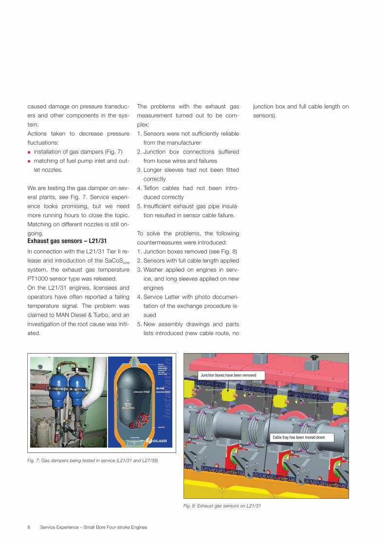
Actions. taken. to. decrease. pressure.
fluctuations:
.� installation.of.gas.dampers.(Fig..7)
.� matching.of.fuel.pump.inlet.and.out-
let.nozzles.
We.are.testing.the.gas.damper.on.sev-
eral. plants,. see. Fig.. 7.. Service. experi-
ence. looks. promising,. but. we. need.
more. running.hours. to.close. the. topic..
Matching.on.different.nozzles.is.still.on-
going.Exhaust gas sensors – L21/31
In.connection.with.the.L21/31.Tier.II.re-
lease.and.introduction.of.the.SaCoSone.
system,. the. exhaust. gas. temperature.
PT1000.sensor.type.was.released.
On. the. L21/31. engines,. licensees. and.
operators.have.often. reported.a. failing.
temperature. signal.. The. problem. was.
claimed.to.MAN.Diesel.&.Turbo,.and.an.
investigation.of.the.root.cause.was.initi-
ated.
The. problems. with. the. exhaust. gas.
measurement. turned. out. to. be. com-
plex:
1..Sensors.were.not.sufficiently. reliable.
from.the.manufacturer
2..Junction. box. connections. suffered.
from.loose.wires.and.failures
3..Longer. sleeves. had. not. been. fitted.
correctly.
4..Teflon. cables. had. not. been. intro-
duced.correctly.
5..Insufficient. exhaust. gas. pipe. insula-
tion.resulted.in.sensor.cable.failure.
To. solve. the. problems,. the. following.
countermeasures.were.introduced:
1..Junction.boxes.removed.(see.Fig..8)
2..Sensors.with.full.cable.length.applied
3..Washer. applied. on. engines. in. serv-
ice,.and.long.sleeves.applied.on.new.
engines
4..Service.Letter.with.photo.documen-
tation.of.the.exchange.procedure.is-
sued
5..New. assembly. drawings. and. parts.
lists.introduced.(new.cable.route,.no.
junction.box.and.full.cable.length.on.
sensors).
Fig. 7: Gas dampers being tested in service (L21/31 and L27/38)
Fig. 8: Exhaust gas sensors on L21/31
Junction boxes have been removed
Cable tray has been moved down

9Service.Experience.–.Small.Bore.Four-stroke.Engines
Cracked piston – L23/30
In.mid-2010,.we.received.a.report.from.
a.vessel.claiming.cracks. in. the.L23/30.
pistons.. After. further. inspections,.
cracks.were. found. in. all. pistons.on. all.
three.genset.engines.on.board..During.
the.second.half.of.2010,.the.same.type.
of.failure.was.reported.to.MAN.Diesel.&.
Turbo.(MDT). from.more.than.ten.differ-
ent.vessels.and.ship.operators..In.some.
cases,. fatigue.cracks.caused.total.pis-
ton. failure. with. consequential. damage.
to. the. engine.. The. cracks. were. found.
in.pistons.that.had.been.in.service.from.
20,000,.but.also.up.to.50,000.hours...
The.pistons.were. sent. for.material. ex-
amination,.which.revealed.that.the.pis-
tons.always.had.a.primary.initial.crack,.
and. one. or. two. typical. consequential.
cracks..
Primary.cracks.start.from.the.inner.con-
necting.bar.towards.the.piston.bottom..
Consequential.cracks. run. from.the. lat-
eral. piston. bolt. accommodation. in. cir-
cumferential.direction.to.the.piston.skirt.
or. through. the.pin.boss.. Investigations.
into. the. origin. of. the. problem. proved.
that.a.too.small.rounding.and.poor.cast-
ing.quality.of.the.surface.roughness.had.
led.to.an.excessively.high.stress.level.
All.engines.affected.were.equipped.with.
pistons. from. the. same. maker.. Nearly.
21,000. pistons. were. in. service. world-
wide.. According. to. an. agreement. be-
tween.the.licensees.involved.and.MDT,.
service.letters.were.issued.from.all.par-
ties.involved..One.general.service.letter.
from.MDT,.and.one.from.each.licensee.
to. the. specific. operator. with. pistons.
installed. from. their. engine. production..
The. service. letters. strongly. recom-
mended. to. replace. the. pistons. due. to.
the.potential.risk.of.engine.damage.and.
serious. personal. injury. for. people.who.
are.near.the.engine.
After. issuing.the.service. letters.regard-
ing. the. pistons,. we. received. reports.
from.operators.with.pistons. from.other.
licensees,. using. other. sub-suppliers,.
stating.that.they.had.also.found.cracks.
in.the.pistons..
Thorough. investigations. of. the. pis-
tons. from. the. involved.makers. are. still.
in.progress. to.eliminate.any. future. risk.
of.engine.damage.and. injury.of.people.
around. the. engines.. During. the. inves-
tigations,. all. involved. licensees. will. be.
approached/involved. to. eliminate. the.
problem. in. cooperation. before. issuing.
new. service. letters.. According. to. our.
knowledge,. there. are. around. 15,000.
high-risk. pistons. in. service. from.differ-
ent.makers..Oval/cracked connecting rod – L23/30
Fig. 9: Cracked pistons on L23/30
Initial damage Next level of damage Final level of damage

10 Service.Experience.–.Small.Bore.Four-stroke.Engines
and L28/32
In. 2011,. we. received. notice. from. op-
erators. claiming. that. their. connecting.
rods.had.an.ovality.at.the.big.end.bore.
exceeding. the. limit.of.0.08.mm..When.
the. connecting. rods. were. sent. for. re-
conditioning,.they.were.often.found.with.
cracks. in. the. serrations,. and. recondi-
tioning.was.therefore.not.possible.
After.thorough.investigation.of.connect-
ing.rods.from.various.engines,.we.found.
the. following. two. root. causes,. which.
depend.on.the.running.hours:
1..If. the. connecting. rod. is. found. with.
high.ovality.and/or.cracks.in.the.ser-
ration. the. first. time. the. connecting.
rod. is.disassembled,. then. this. is. re-
lated. to. incorrect. machining. of. the.
serration. by. the. maker. of. the. con-
necting.rod..The.geometry.of.the.ser-
rations.on.both.sides.of. the.big.end.
was. measured,. and. there. was. not.
correct.correspondence.between.the.
upper. part. and. the. lower. part.. The.
incorrect. geometry. of. the. serrations.
will.have.a.negative. influence.on.the.
ovality.and.the.occurrence.of.cracks..
The. connecting. rods. are. from. engines.
built.by.different.licensees,.but.the.con-
necting. rods.are.mainly. from.one.sub-
supplier.. The. serrations. are,. however,.
not.made.by. this. sub-supplier.. Fig.. 10..
shows. an. example. where. the. require-
ment.of.80%.contact.between.the.mat-
ing. surfaces. between. the. teeth. is. not.
fulfilled.
We. always. recommend. full. measure-
ment.and.reporting.when.a.connecting.
rod. is.disassembled.to.ensure.the.cor-
rect.quality.of.the.connecting.rod.
2...If.the.ovality.or.cracks.are.found.af-
ter. the. second.disassembly. or. later,.
this.is.related.to.failure.during.the.last.
assembly.of.the.connecting.rod..The.
failures.are.often. related. to. inappro-
priate. tightening. of. the. connecting.
rod.and/or.lubrication.of.the.serration.
before.assembly..
As. another. important. issue. related. to.
connecting. rods,.see.Fig..11,.we.have.
seen. broken. connecting. rods. causing.
serious.damage. to. the.engine.and. the.
risk.of.personal.injury..These.failures.are.
due. to. machining. errors. of. the. thread.
in. the.connecting. rod. resulting. in.a. fa-
tigue.crack.initiated.in.the.bottom.of.the.
thread.hole..
Fig. 11: L23/30 connecting rod
Fig. 10: Connecting rod serration (L23/30 and L28/32)

11Service.Experience.–.Small.Bore.Four-stroke.Engines
Broken gear wheel – 9L27/38
The.problem.with.broken.gear.wheels.is.
cracks. between. the. teeth. of. the. inter-
mediate.wheel.driven.by.the.crankshaft..
See.Fig..12.
The. conclusion. is. that. the. crankshaft.
of. a.9-cylinder. engine.has.a. small. up-
and-down. movement. during. rotation,.
thereby. pressing. the. teeth. of. the. gear.
wheels.so.close.to.each.other.that.they.
get.into.full.contact..Thus,.the.stress.in.
the.bottom.of. the. teeth.becomes.high.
and. the. resulting. fatigue.may. initiate. a.
crack..Statistics.show.that.only.9-cylin-
der.engines.with.single.bearing.alterna-
tors.are.affected.
New.two-part.gear.rings.for.installation.
on.the.crankshaft.are.in.production..The.
new. gear. rings.will. increase. the. clear-
ance,.thereby.overcoming.the.problem.
Today,. two-bearing. alternators. are. the.
standard. for. new. 8. and. 9L27/38. en-
gines. and,. thereby,. the. problem. has.
been.eliminated.
A. circular. letter. (CL001-2012). alerting.
the.operator.about. the. issue.has.been.
sent.out,. and.new.gear.wheels.will. be.
delivered.to.the.relevant.operators.
Fig. 12: Broken gear wheel from L27/38

12 Service.Experience.–.Small.Bore.Four-stroke.Engines
Liner and ring groove wear – L27/38
A.high.liner.and.ring.groove.wear.on.the.
L27/38. engine. was. a. problem. earlier,.
and.various.solutions.have.been.tested.
in. the. field.. As. a. result,. the. liner. wear.
is.now.kept.below.10.µm/1,000.hours,.
and. the. ring. groove.wear. rate. can. be.
kept.below.the.target.limit,.i.e..less.than.
5. µm/1,000. hours.. The. entire. solution.
package.consists.of:
1..Changed.cylinder.liner.support
2..Changed.piston.top.land.clearance
3..Improved.scraper.ring.groove.drain
4..Changed. compression. ring. shape.
and.material
5..Cooling. jacket.with. controlled.water.
flow
6..Low-sac.fuel.nozzle.
All. the.changes.were. tested.and. intro-
duced.in.2006,.see.Figs..13.and.14.
Nevertheless,. some. operators. were.
still.claiming.high.wear.rates.in.the.ring.
grooves,.i.e..more.than.0.25.mm.within.
12,000.hours.
Investigation. of. these. cases. showed.
that.not.all.engines.built.after.2006.were.
equipped.with.the.mentioned.package,.
which.effectively.will.cure.the.problem.Bush for cam follower – V28/32S
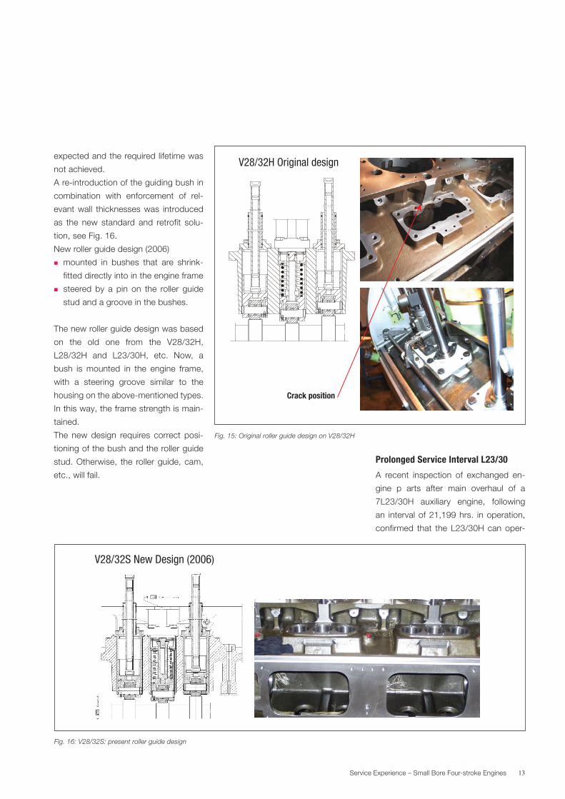
Due. to. cracks. in. the. engine. frame. in.
the.area.of.the.roller.guide’s.12-o’clock.
stud.(see.Fig..15),.as.well.as.cost-down.
considerations,. the.original. roller.guide.
design.was.simplified.and.integrated.in.
the.engine.frame.
Original.roller.guide.design:
.� mounted. in. the. roller.guide.housing,.
which.is.mounted.in.the.engine.frame
.� steered. by. a. pin. on. the. roller. guide.
stud.and.a.groove.in.the.housing.
The. original. roller. guide. design. was.
working. very. well,. but. the. frame. was.
weakened.by.the.cut-out.for.the.hous-
ing,. and. cracks. developed. around. the.
lower.cylinder.cover.stud..Especially.the.
gas.engine.version.was.affected.
Service.experience.revealed.afterwards.
that,. with. an. improved. design. of. the.
roller. guide,. the. wear. rates. of. roller.
guides.and.bushings.were.not.as.low.as.
Fig. 13: L27/38: improvement on hardware
1998 to 2002
3,000.hrs.,.
HFO.Propul-
sion
2006 →
6,200.hrs.,.
HFO.Propul-
sion
wear rate[mm 1000 h]
01998 1999
0.01
2000 2001 2002 2003 2004 2005 2006 2007 2008year
0.02
0.04
0.06
0.8
0.1
0.1220001st customer engine
2001liner worn outafter 1500 hrs
2003LTC-Ringnew piston rings 2005
free liner 2006 packagefree linerlow sack nozzle
Fig. 14: 27/38 liner wear rates
13Service.Experience.–.Small.Bore.Four-stroke.Engines
expected.and.the.required.lifetime.was.
not.achieved.
A.re-introduction.of.the.guiding.bush.in.
combination. with. enforcement. of. rel-
evant.wall. thicknesses.was. introduced.
as. the. new. standard. and. retrofit. solu-
tion,.see.Fig..16.
New.roller.guide.design.(2006)
.� mounted. in. bushes. that. are. shrink-
fitted.directly.into.in.the.engine.frame
.� steered. by. a. pin. on. the. roller. guide.
stud.and.a.groove.in.the.bushes.
The.new.roller.guide.design.was.based.
on. the. old. one. from. the. V28/32H,.
L28/32H. and. L23/30H,. etc.. Now,. a.
bush. is. mounted. in. the. engine. frame,.
with. a. steering. groove. similar. to. the.
housing.on.the.above-mentioned.types..
In.this.way,.the.frame.strength.is.main-
tained.
The. new. design. requires. correct. posi-
tioning.of.the.bush.and.the.roller.guide.
stud..Otherwise,. the. roller.guide,.cam,.
etc.,.will.fail.
Prolonged Service Interval L23/30
A. recent. inspection. of. exchanged. en-
gine. p. arts. after. main. overhaul. of. a.
7L23/30H. auxiliary. engine,. following.
an. interval.of.21,199.hrs.. in.operation,.
confirmed. that. the. L23/30H.can.oper-
V28/32H Original design
Crack position
Fig. 15: Original roller guide design on V28/32H
Fig. 16: V28/32S: present roller guide design
V28/32S New Design (2006)
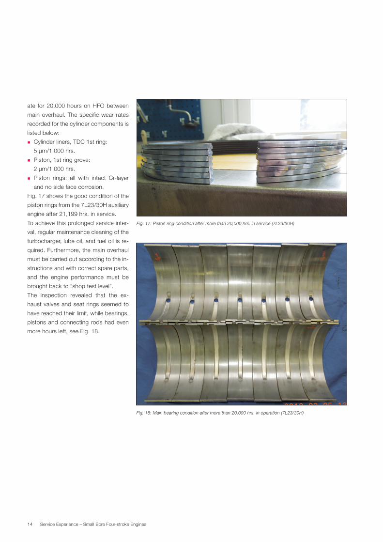
14 Service.Experience.–.Small.Bore.Four-stroke.Engines
ate. for.20,000.hours.on.HFO.between.
main.overhaul..The.specific.wear. rates.
recorded.for.the.cylinder.components.is.
listed.below:
.� Cylinder.liners,.TDC.1st.ring:..
5.µm/1,000.hrs.
.� Piston,.1st.ring.grove:..
2.µm/1,000.hrs.
.� Piston. rings:. all. with. intact. Cr-layer.
and.no.side.face.corrosion.
Fig..17.shows.the.good.condition.of.the.
piston.rings.from.the.7L23/30H.auxiliary.
engine.after.21,199.hrs..in.service.
To.achieve.this.prolonged.service.inter-
val,.regular.maintenance.cleaning.of.the.
turbocharger,.lube.oil,.and.fuel.oil.is.re-
quired..Furthermore,.the.main.overhaul.
must.be.carried.out.according.to.the.in-
structions.and.with.correct.spare.parts,.
and. the. engine. performance. must. be.
brought.back.to.“shop.test.level”.
The. inspection. revealed. that. the. ex-
haust.valves.and.seat.rings.seemed.to.
have.reached.their.limit,.while.bearings,.
pistons.and.connecting. rods.had.even.
more.hours.left,.see.Fig..18..
Fig. 18: Main bearing condition after more than 20,000 hrs. in operation (7L23/30H)
Fig. 17: Piston ring condition after more than 20,000 hrs. in service (7L23/30H)

15Service.Experience.–.Small.Bore.Four-stroke.Engines
New roller on valve cam – L28/32H
A.number.of.damaged.valve.cams.(bal-
listic. type). were. claimed. from. the. op-
erators,. and. the. root. cause. has. been.
identified. to. be. insufficient. material.
properties. and/or. an. incorrect. harden-
ing.process,.see.Fig..19..
A.solution. involving.the.release.of.“soft.
shoulder”.cams.(see.Fig..20).has.been.
introduced,.similar.to.the.ones.used.on.
newer. engine. types,. as. this. design. is.
easier.to.handle.production-wise..
The.below.production.procedure.must.
be. followed. to. obtain. the. best. soft.
shoulders:
1..Roller.is.pre-machined.
2..Roller.is.hardened.to.a.specified.hard-
ness. and,. more. importantly,. to. . a.
specified.hardening.depth
3..Roller. is.grinded.to.specified.dimen-
sions
4..Area.to.create.soft.shoulders.to.be.ma-
chined.away..This.machining.ensures.
that. hardened. material. is. removed.
and.that.the.remaining.non-hardened.
material.has.the.wanted.flexibility.
This.design.variant.will.also.mean.a.cost.
reduction.for.some.engine.producers.
Fig. 19: Camshaft pitting – L28/32 fuel cam with 5,000 operating hours
Fig. 20: L28/32 soft shoulder cam design

16 Service.Experience.–.Small.Bore.Four-stroke.Engines
HFO service experience
Sticking. fuel.pumps.have.always.been.
an.annoying.problem.for.engines.oper-
ating. on. heavy. fuel.. Lacquer. deposits.
on.the.lower.part.of.the.plunger.reduce.
the.clearance.and.can. lead. to.sticking.
of. the.plunger,.especially.after.standby.
periods.and.change.to.diesel.fuel..
High. viscosity. and. low-quality. HFO.
leads.to.a.higher.temperature.to.achieve.
the.correct.injection.viscosity..The.high-
er. temperature. increases. the. tendency.
to.lacquering.in.the.lower.drain.grooves..
Furthermore,.when.the.drain.bores.are.
filled/blocked. by. coke,. the. leak. oil. will.
be.trapped.there,.see.Figs..21.and.22.
The.L16/24.does.not.have.this.problem,.
and. it. seems. that. a. special. sealing. oil.
system. with. controlled. oil. flow. in. the.
lower. part. of. the. pump. element. mini-
mises.the.problem.
In.response.to.the.above,.investigations.
are. ongoing. to. eliminate. the. problem.
also.on.engines.larger.than.the.L16/24.
A.similar.system.for.the.other.small.four-
stroke. engine. pumps. has. been. func-
tion-tested. and. will. go. into. field. test..
Another. approach. to. lower. the. risk. of.
lacquering.is.to.keep.the.fuel.tempera-
ture. in. the. pumps. as. low. as. possible.
within.the.limits.for.viscosity.and.to.have.
a.high-circulating.fuel.flow.to.maintain.a.
sufficient.standby.temperature.
Fig. 21: L21/31 pump
From report:
Fig. 22: L21/31 pump plunger
From report:
17Service.Experience.–.Small.Bore.Four-stroke.Engines
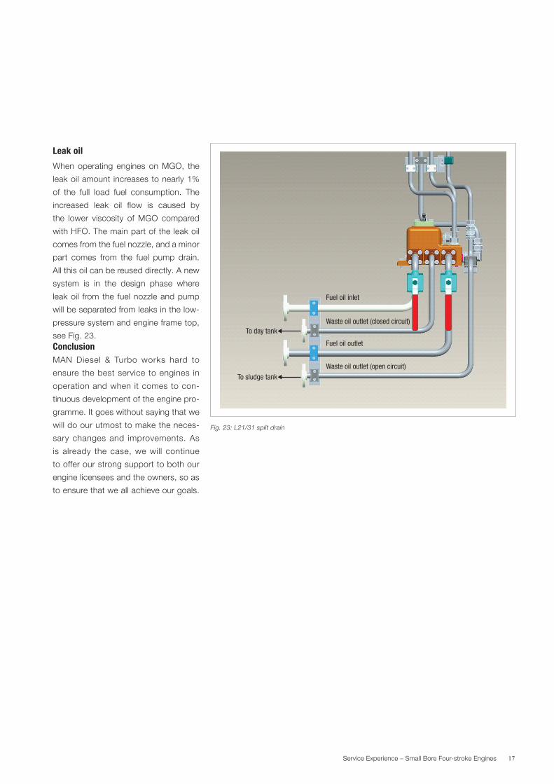
Leak oil
When. operating. engines. on.MGO,. the.
leak.oil.amount. increases.to.nearly.1%.
of. the. full. load. fuel. consumption.. The.
increased. leak. oil. flow. is. caused. by.
the. lower. viscosity. of.MGO. compared.
with.HFO..The.main.part.of.the.leak.oil.
comes.from.the.fuel.nozzle,.and.a.minor.
part. comes. from. the. fuel. pump. drain..
All.this.oil.can.be.reused.directly..A.new.
system. is. in. the. design. phase. where.
leak.oil. from.the. fuel.nozzle.and.pump.
will.be.separated.from.leaks.in.the.low-
pressure.system.and.engine.frame.top,.
see.Fig..23.ConclusionMAN. Diesel. &. Turbo. works. hard. to.
ensure. the.best.service. to.engines. in.
operation.and.when. it.comes.to.con-
tinuous.development.of.the.engine.pro-
gramme..It.goes.without.saying.that.we.
will.do.our.utmost.to.make.the.neces-
sary.changes.and. improvements..As.
is.already. the.case,.we.will. continue.
to.offer.our.strong.support.to.both.our.
engine.licensees.and.the.owners,.so.as.
to.ensure.that.we.all.achieve.our.goals.
Fuel oil inlet
To day tank
To sludge tank
Waste oil outlet (closed circuit)
Fuel oil outlet
Waste oil outlet (open circuit)
Fig. 23: L21/31 split drain


MAN Diesel & TurboTeglholmsgade.412450.Copenhagen.SV,.DenmarkPhone. +45.33.85.11.00Fax. [email protected]
MAN.Diesel.&.Turbo.–.a.member.of.the.MAN.Group
All.data.provided.in.this.document.is.non-binding..This.data.serves.informational.purposes.only.and.is.especially.not.guaranteed.in.any.way..Depending.on.the.subsequent.specific.individual.projects,.the.relevant.data.may.be.subject.to.changes.and.will.be.assessed.and.determined.individually.for.each.project..This.will.depend.on.the.particular.characteristics.of.each.individual.project,.especially..specific.site.and.operational.conditions..Copyright.©.MAN.Diesel.&.Turbo..5510-0118-00ppr.Aug.2012.Printed.in.Denmark