
Service Bulletin Bulletin No.: 16-NA-102 Date: August, 2019 · Page 6 August, 2019 Bulletin No.:...
17
Copyright 2019 General Motors LLC. All Rights Reserved. Service Bulletin Bulletin No.: 16-NA-102 Date: August, 2019 TECHNICAL Subject: Duramax Diesel Hard Start, No Start, DTCs P0087, P0088, P0191, P128E or Injection Pump Replacement Brand: Model: Model Year: VIN: Engine: Transmission: from to from to Chevrolet Express 2010 2016 Diesel (RPOs LML or LGH) Silverado 2500/3500 GMC Savana Sierra 2500/3500 Involved Region or Country North America, Israel Condition Some customers may comment on one or more of the following conditions: • Hard start • No start Some technicians may find one or more of the following DTCs set in the Engine Control Module (ECM): • P0087: Fuel Rail Low Pressure • P0088: Fuel Rail High Pressure • P0191: Fuel Rail Pressure Sensor Performance • P128E: Fuel Rail Pressure Performance ⇒ Normal SI Diagnostics may be inconclusive or lead to Fuel Injection Pump replacement. Service Procedure Fuel Injection Pump Diagnosis Procedure Complete the current SI diagnostics for any symptoms or DTCs found. If the current SI diagnostic has led to Fuel Injection Pump replacement, replace the fuel injection pump. Refer to Fuel Injection Pump Replacement in SI. Once the fuel injection pump is removed, remove the Fuel Pressure Regulator 1 and inspect for debris that can be picked up with a magnet. Note: Clean the area around Pressure Regulator 1 before removal. It is possible that road debris could find its way into the regulator port when it is removed. A small piece of dirt on Pressure Regulator 1 does not qualify for the fuel system repairs recommended in this Bulletin. 2698603
Transcript of Service Bulletin Bulletin No.: 16-NA-102 Date: August, 2019 · Page 6 August, 2019 Bulletin No.:...

Copyright 2019 General Motors LLC. All Rights Reserved.
Service BulletinBulletin No.: 16-NA-102
Date: August, 2019
TECHNICAL
Subject: Duramax Diesel Hard Start, No Start, DTCs P0087, P0088, P0191, P128E or InjectionPump Replacement
Brand: Model:Model Year: VIN: Engine: Transmission:
from to from to
ChevroletExpress
2010 2016 Diesel (RPOsLML or LGH)
Silverado2500/3500
GMCSavana
Sierra2500/3500
Involved Region or Country North America, Israel
Condition
Some customers may comment on one or more of the following conditions:• Hard start• No startSome technicians may find one or more of the following DTCs set in the Engine ControlModule (ECM):• P0087: Fuel Rail Low Pressure• P0088: Fuel Rail High Pressure• P0191: Fuel Rail Pressure Sensor Performance• P128E: Fuel Rail Pressure Performance
⇒ Normal SI Diagnostics may be inconclusive or lead to Fuel Injection Pumpreplacement.
Service ProcedureFuel Injection Pump Diagnosis Procedure
Complete the current SI diagnostics for any symptomsor DTCs found.If the current SI diagnostic has led to Fuel InjectionPump replacement, replace the fuel injection pump.Refer to Fuel Injection Pump Replacement in SI. Oncethe fuel injection pump is removed, remove the FuelPressure Regulator 1 and inspect for debris that can bepicked up with a magnet.Note: Clean the area around Pressure Regulator 1before removal. It is possible that road debris could findits way into the regulator port when it is removed. Asmall piece of dirt on Pressure Regulator 1 does notqualify for the fuel system repairs recommended in thisBulletin.
2698603

Page 2 August, 2019 Bulletin No.: 16-NA-102
Remove the Fuel Injection Pump / PressureRegulator 1 for inspection.
3541158
If Pressure Regulator 1 has no debris that can bepicked up with a magnet on the screen, continue withFuel Injection Pump replacement.
3541164
3541165
If there are only a few pieces of debris that can bepicked up with a magnet found on PressureRegulator 1, remove the Fuel Rail Pressure Sensorand/or Fuel Pressure Regulator 2 (Pressure ReliefValve) for inspection.
3541168

Bulletin No.: 16-NA-102 August, 2019 Page 3
3541159
If additional debris that can NOT be picked up with amagnet (Contamination) is found on the Fuel PressureRegulator 1, Fuel Rail Pressure Sensor, and/or FuelPressure Regulator 2 (Pressure Relief Valve), refer toPIP5370 and Contaminants-in-Fuel Diagnosis. DONOT perform the repair listed in this bulletin.
Important: If debris that can be picked up with amagnet as described above is found, complete therepairs listed below:
Service Procedure For All VansCleaning and Flushing Procedure1. Replace all the parts listed in the Parts Information
below.2. Clean and flush all fuel chassis lines, filter pipes,
and other engine mounted fuel system pipes thatare not being replaced.
3. The fuel filter housing must be cleaned with a newfuel filter installed.
4. The fuel tank and fuel sender must be cleaned andflushed.
Note: The Indirect Fuel Injector (Hydrocarbon Injector)and its fuel lines must be purged of air any time it isremoved or replaced. Failure to do so may damage theinjector. Perform the Diesel Particulate Filter (DPF)Regeneration Enable any time the indirect injector or itsfuel lines are opened/removed or replaced. This willforce regeneration as soon as conditions allow and willpurge any air from the system. Refer to DieselParticulate Filter (DPF) Regeneration Enable in SI.
Service Procedure For All P/U TrucksRemoval Procedure
Warning: The ignition must be in the off positionand all electrical loads must be turned off beforeservicing any electrical component. Failure to do somay result in personal injury or damage to thevehicle.
1871640
1. Disconnect the water in fuel sensor wiringpigtail (2) from the engine wiring harness electricalconnector.
4258780
2. Remove the fuel filter assembly (2). Refer to FuelFilter Assembly Replacement in SI.

Page 4 August, 2019 Bulletin No.: 16-NA-102
5334169
3. Remove the fuel filter bracket (5). Refer to FuelFilter Bracket Replacement in SI.
2382530
4. Disengage the fuel return line by pulling upward onthe cylindrical locking sleeve (1).
5. Remove the fuel return line (2) from the fuelinjectors (3).
6. Repeat step 5 for the remaining injectors.
7. Remove the fuel return pipe bracket bolt from leftvalve cover.
4228683
8. Disconnect the fuel return hose from the fuelfeed pipe.
9. Remove the fuel injector fuel return lineassembly (1) and discard.

Bulletin No.: 16-NA-102 August, 2019 Page 5
4228685
10. Remove the bolt (1) that secures the fuel feed pipebracket.
4228687
11. Remove the fuel line at the quick connect fitting (1).12. Remove the fuel feed pipe and discard.
2394330
13. Remove the indirect fuel injector fasteners (1, 2).14. Remove the indirect injector fitting.15. Remove and discard the indirect injector using the
CH-49736 tool.
2407046
16. Remove the two right bank fuel injection fuel feedpipe bracket fasteners (1).
17. Remove and discard the four fuel injection fuelfeed pipes (2).

Page 6 August, 2019 Bulletin No.: 16-NA-102
2370205
18. Remove the right bank fuel rail fasteners (1).19. Remove and discard the right bank fuel injection
fuel rail assembly (2).
2407097
20. Remove the two left bank fuel injection fuel feedpipe bracket fasteners (1).
21. Remove and discard the four fuel injection fuelfeed pipes (2).
2369972
22. Disconnect the fuel pressure relief valve electricalconnector (1).
2369973
23. Disconnect the fuel pressure sensor electricalconnector (1).

Bulletin No.: 16-NA-102 August, 2019 Page 7
2369984
24. Remove the fuel rail heat shield fasteners (1).
2369985
25. Remove the left bank fuel injection railfasteners (1).
26. Remove the heat shield (2).27. Remove and discard the left bank fuel injection fuel
rail assembly (3).
Caution: Label all the injector electrical connectorsbefore the connectors are removed in order to preventreconnecting to the wrong injector. Failure to properlyconnect the injectors in the correct sequence will causesevere engine damage.
2408253
28. Disconnect the fuel injector electricalconnectors (1).
2408258
29. Remove the fuel injector bracket bolts (1).

Page 8 August, 2019 Bulletin No.: 16-NA-102
4663244
30. Using one of the fuel injector brackets (2), installEN-49774 Fuel Injector Puller (1) into the bolt holein the fuel injector bracket.
31. Install a suitable wrench onto EN-49774 FuelInjector Puller and work the tool outward until thefuel injector (3) releases from its seat.
32. Remove the EN-49774 Fuel Injector Puller.
4663305
33. Remove the fuel injector bracket (1) and fuelinjector.
34. Discard the diesel fuel injector (2).35. Repeat steps 30-34 for each injector.
Injector Bore Cleaning Procedure
Warning: Wear safety glasses to avoid eyedamage.
Caution: Do not allow excessive amounts of solvent togo into the cylinder during cleaning. Failure to do somay cause engine damage upon startup.
1335621
1. Install the EN - 47909–2 Radial Brush to theEN - 47909–1 T-Handle.
2. Insert the EN-47909–2 Radial Brush into theinjector bore and rotate the EN-47909–1 T-Handleto break loose any carbon deposits from theinjector bore walls and the combustion deck hole.
3. Using compressed air, evacuate any debris fromthe injector bore.
4. Remove the EN-47909–2 Radial Brush from theEN-47909–1 T-Handle.
5. Install the EN - 47909–3 Axial Brush to theEN- 47909–1 T-Handle.
6. Insert the EN-47909–3 Axial Brush into theinjector bore and rotate the EN-47909–1 T-Handlewhile also applying a slight downward pressure toforce the brush ends into the bottom corners of theinjector bore.
7. Using compressed air, evacuate any debris fromthe injector bore.
8. Lightly dampen EN - 47909–20 Cotton Swab withTop Engine Cleaner and wipe away any depositsfrom the injector bore. Refer to Adhesives, Fluids,Lubricants, and Sealers in SI.
9. Inspect the injector bore for any deposits andrepeat brushing if necessary.
Warning: Keep hands and face clear of glow plugholes while cranking. Hot liquid or gases may beexpelled during cranking.
10. If necessary, crank the engine to expel any solventbefore starting the engine.
Bulletin No.: 16-NA-102 August, 2019 Page 9
11. Remove the glow plugs;– Refer to Glow Plug Replacement - Bank 1– Refer to Glow Plug Replacement - Bank 2
12. Disable the fuel system.13. Disconnect the Crank Shaft Position (CKP) sensor
electrical connector.14. Crank the engine to expel excessive solvent.15. Using the EN-47909–20 Cotton Swab wipe the
injector bore clean of any solvent and/or debris.16. Connect the CKP sensor electrical connector.17. Enable the fuel system.18. Install the glow plugs;
– Refer to Glow Plug Replacement - Bank 1– Refer to Glow Plug Replacement - Bank 2
Installation ProcedureCaution: Refer to Component Fastener TighteningCaution in SI..Note: It may be useful to take a photo of the FuelInjector Flow Rate value on each injector prior toinstallation.
4663364
Note: Lubricate the NEW fuel injector O-ring seals withclean engine oil.
1. Install combustion Fuel Injector Seal (1).2. Install fuel injector seal ring (2).3. Install fuel injector seal ring (3).
4663305
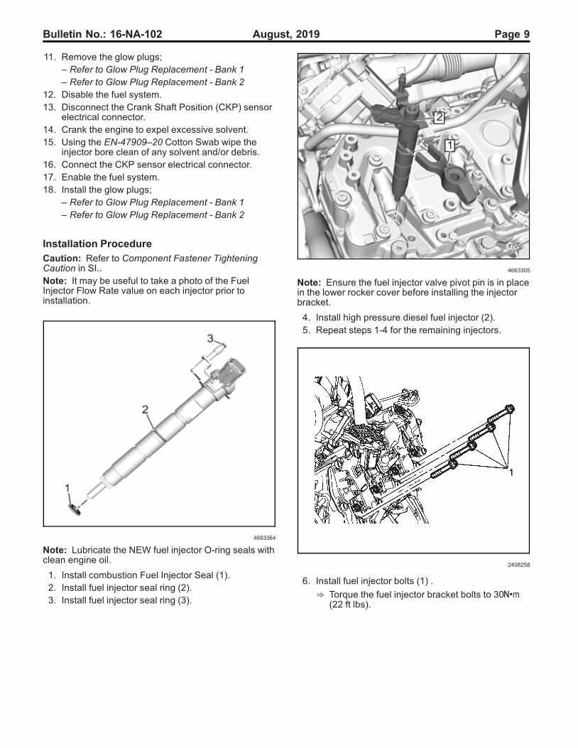
Note: Ensure the fuel injector valve pivot pin is in placein the lower rocker cover before installing the injectorbracket.
4. Install high pressure diesel fuel injector (2).5. Repeat steps 1-4 for the remaining injectors.
2408258
6. Install fuel injector bolts (1) .
⇒ Torque the fuel injector bracket bolts to 30Y(22 ft lbs).

Page 10 August, 2019 Bulletin No.: 16-NA-102
2408253
7. Connect the fuel injector electrical connectors (1).Note: It is recommended to insert the High PressureFuel Pipe, Rail to Rail under the turbocharger prior toinstalling the left fuel rail. Also, leave the line end capsin place while inserting this pipe.
2369985
8. Install the left side fuel injection fuel railassembly (3) and heat shield (2).
9. Install the left side fuel injection rail fasteners (1).
⇒ Torque the fuel injector bracket bolts to 25Y(18 ft lbs).
2369984
10. Install the left side fuel rail heat shieldfasteners (1).
⇒ Torque the fuel rail heat shield fasteners to25Y (18 ft lbs).
2369972
11. Connector the left side fuel pressure relief valveelectrical connector (1) and pressure sensorelectrical connector.
12. Ensure all lines, injectors and rail fittings are cleanand dry prior to assembly.

Bulletin No.: 16-NA-102 August, 2019 Page 11
2407097
Caution: Ensure proper torque of the fuel injectorlines. An under-torqued fuel injector line will not sealproperly and an over-torqued fuel injector line maydamage the fuel injector fitting. An improperly sealed ordamaged fuel injector line or fuel injector fitting, willcause a fuel leak.13. Install the left side fuel injection fuel feed pipes (2).
⇒ Torque the fuel injection fuel feed pipes fittingsin alternating increments to 30Y (22 ft lbs).
14. Install the left side fuel injection fuel feed pipebracket fasteners (1).
⇒ Torque the fuel injection fuel feed pipes bracketfasteners to 10Y (89 in lbs).
2370205
15. Position the right side fuel injection fuel railassembly (2) and install the fuel rail fasteners (1).
⇒ Torque the fuel rail fasteners to 25Y (18ft lbs).
16. Ensure right side lines, injectors and rail fittings areclean and dry prior to assembly.
2407046
Caution: Ensure proper torquing of the fuel injectorline. An under-torqued fuel injector line will not sealproperly and an over-torqued fuel injector line maydamage the fuel injector fitting. An improperly sealed ordamaged fuel injector line or fuel injector fitting willcause a fuel leak.17. Install the right side fuel injection fuel feed
pipes (2).
⇒ Torque the fuel injection fuel feed pipes fittingsin alternating increments to 30Y (22 ft lbs).
18. Install the right side fuel injection fuel feed pipebracket fasteners (1).
⇒ Torque the fuel injection fuel feed pipes bracketfasteners to 10Y (89 in lbs).

Page 12 August, 2019 Bulletin No.: 16-NA-102
5334311
19. Clean the fuel injection fuel feed pipes and fittingsfor all 8 cylinders and apply sealant at thefittings (1) to prevent moisture and debris fromcollecting. Refer to Adhesives, Fluids, Lubricants,and Sealers in SI.
2394333
20. Install the indirect fuel injector (2).
⇒ Torque the indirect fuel injector fittings to 45Y(33 ft lbs).
2394330
21. Install the two indirect fuel injector fasteners (1, 2).
⇒ Torque the indirect fuel injector fasteners to25Y (18 ft lbs).

Bulletin No.: 16-NA-102 August, 2019 Page 13
4228687
22. Connect the fuel feed pipe Quick ConnectFitting (1).
4228685
23. Install the fuel feed bracket bolt (1).
⇒ Torque the fuel feed bracket bolt to 25Y (18ft lbs).
2376586
24. Install the NEW fuel injector fuel return lineassembly (1).
4228683
Note: After connecting the fuel return hose to the fuelfeed pipe, lock the fuel return line by pushing thecylindrical locking sleeve towards the connection point.
25. Connect the fuel return hose (1) to the fuel feedpipe (2).

Page 14 August, 2019 Bulletin No.: 16-NA-102
2382530
26. With the cylindrical locking sleeve (1) released inthe upward position, install the fuel return line tothe fuel injector.
27. Press down on the locking sleeve (1) to secure theconnection on all the injectors.
28. Install the fuel return pipe bracket bolt to left valvecover.
5334169

Bulletin No.: 16-NA-102 August, 2019 Page 15
29. Install the fuel filter bracket. Refer to Fuel FilterBracket Replacement in SI.
4258780
30. Install the fuel filter housing assembly. Refer toFuel Filter Housing Assembly Replacement in SI.
31. Prior to installing fuel injection pump replace theFuel Feed hose on the back of the injection pump.Refer to Fuel Feed Hose Replacement in SI.
32. Install the fuel injection pump. Refer to FuelInjection Pump Replacement in SI.
Cleaning and Flushing Procedure1. Clean and flush all fuel chassis lines, filter pipes,
and other engine mounted fuel system pipes thatare not being replaced.
2. The fuel filter housing must be cleaned with a newfuel filter installed.
3. The fuel tank and fuel sender must be cleaned andflushed.
Note: The Indirect Fuel Injector (Hydrocarbon Injector)and its fuel lines must be purged of air any time it isremoved or replaced. Failure to do so may damage theinjector. Perform the Diesel Particulate Filter (DPF)Regeneration Enable any time the indirect injector or itsfuel lines are opened/removed or replaced. This willforce regeneration as soon as conditions allow and willpurge any air from the system. Refer to DieselParticulate Filter (DPF) Regeneration Enable in SI.
TIPAfter repairs, the following may help with fuel systempriming:• Prime fuel to the fuel filter housing.• Relieve air by opening the bleed screw at the filter
housing.• Pump the priming ball again until no more air
escapes and close the bleed screw.• Prime until the priming ball is hard.• There should be at least 10 psi fuel pressure on
the fuel system pressure gauge attached to thefuel system service port (Schrader valve).
• Crank the engine for up to 15 seconds.• Key off for one minute.
Repeat the above steps until the engine starts. It isnormal for the engine to start and then stall when thefuel system loses prime. Repeated priming will alleviatethis concern.
Parts Information
PartNumber Description Qty.
Silverado / Sierra (LML) Silverado /Sierra (LGH) Express / Savana (LGH)
2011 2012 2013 2014 2015 2016 2011 2012 2010 2011 2012 2013 2014 2015 2016
12664429 FILTERKIT, FUEL
1 X X X X X X X X X X X X X X
88917036 FILTER, OIL 1 X X X X X X X X X X X X X X X
97363570 GASKET, CTRINT MANIF
2 X X X X X X X X X X X X X X X
12635466 GASKET, EGRVLV (LOCR A)
2 X X X X X X X X X X X X X X X
98062923 GASKET, EGRVLV (LOCR B)
2 X X X X X X X X X X X X X X X
97223686GASKET, ENG
COOLTHERM HSG
2X X X X X X X X X X X X X X X
15126137 GASKET-EXHMANIF PIPE
1 X X X X X X X
97188685GASKET, EXH
TURBOINL PIPE
2X X X X X X X
97192618GASKET, EXH
TURBOINL PIPE
2X X X X X X X
12627897GASKET-TURBO OILFEED PIPE
1X X X X X X X

Page 16 August, 2019 Bulletin No.: 16-NA-102
12637218GASKET-TURBO OILRTN PIPE
1X X X X X X X
12639312HOSE ASM-
FUEL FEED (RHSIDE OF PUMP,
W/ BANJ)
1X X X X X X X X X X X X X X X
12639000 HOSE ASM-FUEL RTN
1 X X X X X X X X X X X X X X X
12661071INJECTOR
ASM-INDIRECT FUEL
1X X X X X X X X X X X X X X X
12656313 PIPE ASM-FUEL FEED
1 X X X X X X X X X X X X X X X
94011618SEAL, COLDSTART FUELFEED VLV(O RING)
1X X X X X X X
12625100SEAL, COLDSTART FUELFEED VLV(O RING)
1X X X X X X X X X X X X X X X
94036238SEAL, OIL LVLIND TUBE(O RING)
1X X X X X X X
94011603SEAL, THERMBYPASS PIPE
(O RING)
1X X X X X X X X X X X X X X X
12670466PIPE ASM-FUEL HIGHPRESS
1X X X X X X X X X X X X X X X
12641590 SWITCH ASM,ENG FUELVAC
1 X X X X X X X
12631851 SEAL-TURBOAIR INL ADAP
1 X X X X X X X X X X X X X X X
97224993 SENSOR ASM,FUEL TEMP
1 X X X X X X X X
12676436SENSOR ASM-
WAT INFUEL IND
1X X X X X
98065521 GASKET-EGRVLV CLR
1 X X X X X X X X
12670460PIPE ASM-FUEL HIGH
PRESS (CYL 2& 7)
2X X X X X X X X
12670468PIPE ASM-FUEL HIGH
PRESS (CYL 1& 8)
2X X X X X X X X
12670469PIPE ASM-FUEL HIGH
PRESS (CYL 3& 6)
2X X X X X X X X
12670471PIPE ASM-FUEL HIGH
PRESS (CYL 4& 5)
2X X X X X X X X
12670474PIPE ASM-FUEL HIGH
PRESS (LEFTSIDE OF PUMP)
1X X X X X X X X
12670475PIPE ASM-FUEL HIGH
PRESS (RIGHTSIDE OF PUMP)
1X X X X X X X X
12629458 SEAL-TURBOAIR INL ADAP
1 X X X X X X X X
12627913 SEAL-UPR INTMANIF
1 X X X X X X X X
12645582HOSE ASM-FUEL RTN
(LEFT RAIL TOFEED PIPE)
1X X X X X X
98065523 GASKET-EGR PIPE
1 X X X X X X
12672028
PUMP KIT-FUEL(CONTAINSFUEL PUMP,INJECTORS &
RAILS)
1
X X X X X X
98070023 GASKET-EGRVLV CLR
1 X X X X X X X X X
12672027
PUMP KIT-FUEL(CONTAINSFUEL PUMP,INJECTORS &
RAILS)
1
X X X X X X X X X
12636266 HOSE-FUEL RTN
1 X X X X X X X

Bulletin No.: 16-NA-102 August, 2019 Page 17
12641356 PIPE ASM-FUEL FEED
1 X X X X X X X
12670457PIPE ASM-FUEL HIGH
PRESS (CYL 6)
1X X X X X X X
12670463PIPE ASM-FUEL HIGH
PRESS (CYL 7)
1X X X X X X X
12670456PIPE ASM-FUEL HIGH
PRESS (CYL 8)
1X X X X X X X
12670454PIPE ASM-FUEL HIGHPRESS
1X X X X X X X
12670465PIPE ASM-FUEL HIGH
PRESS (CYL 1)
1X X X X X X X
12670460PIPE ASM-FUEL HIGH
PRESS (CYL 2)
1X X X X X X X
12670464PIPE ASM-FUEL HIGH
PRESS (CYL 3)
1X X X X X X X
12670459PIPE ASM-FUEL HIGH
PRESS (CYL 4OR 5)
2X X X X X X X
12670453PIPE ASM-FUEL HIGHPRESS
1X X X X X X X
12639101 PIPE ASM-FUEL RTN
1 X X X X X X X
26020642SEAL, P/S
PUMP RSVR(O RING)
1X X X X X X X
97368325 GASKET-CTRINT MANIF
1 X X X X X X X
Warranty InformationFor vehicles repaired under the Powertrain coverage,use the following labor operation. Reference theApplicable Warranties section of Investigate VehicleHistory (IVH) for coverage information.
LaborOperation Description Model Labor Time
4080558*
Diagnoseand Clean/Repair
CompleteFuel System
For all P/UTrucks 12.9 hrs
For all Vans 21.0 hrs
*This is a unique Labor Operation for bulletin use only.
Version 7
Modified
Released March 31, 2016Revised April 11, 2016 – Updating the Qty. column of the Parts Information table.Revised April 29, 2016 – Updating the Parts Information table.Revised October 26, 2016 – Updating the Parts Information table.Revised February 03, 2017 – Updating the Service Procedure.Revised March 2, 2017 – Updating the Service Procedure.Revised August 19, 2019 - Removed information in regard to turbocharger removal andinstallation for the p/u trucks, update the labor time for p/u trucks in the WarrantyInformation section and update the Parts Information section.
GM bulletins are intended for use by professional technicians, NOT a "do-it-yourselfer". They are written to inform thesetechnicians of conditions that may occur on some vehicles, or to provide information that could assist in the properservice of a vehicle. Properly trained technicians have the equipment, tools, safety instructions, and know-how to do ajob properly and safely. If a condition is described, DO NOT assume that the bulletin applies to your vehicle, or that yourvehicle will have that condition. See your GM dealer for information on whether your vehicle may benefit from theinformation.
WE SUPPORT VOLUNTARYTECHNICIAN
CERTIFICATION


