ServerIron Switching and Routing Guide Release 12.1 · 53-1001742-01 20 January 2010 ® ServerIron...
478
53-1001742-01 20 January 2010 ® ServerIron ADX Switch and Router Guide Supporting ServerIon TrafficWorks version 12.1.00
Transcript of ServerIron Switching and Routing Guide Release 12.1 · 53-1001742-01 20 January 2010 ® ServerIron...

53-1001742-0120 January 2010
®
ServerIron ADXSwitch and Router Guide
Supporting ServerIon TrafficWorks version 12.1.00
Copyright © 2010 Brocade Communications Systems, Inc. All Rights Reserved.
Brocade, the B-wing symbol, BigIron, DCX, Fabric OS, FastIron, IronPoint, IronShield, IronView, IronWare, JetCore, NetIron, SecureIron, ServerIron, StorageX, and TurboIron are registered trademarks, and DCFM, Extraordinary Networks, and SAN Health are trademarks of Brocade Communications Systems, Inc., in the United States and/or in other countries. All other brands, products, or service names are or may be trademarks or service marks of, and are used to identify, products or services of their respective owners.
Notice: This document is for informational purposes only and does not set forth any warranty, expressed or implied, concerning any equipment, equipment feature, or service offered or to be offered by Brocade. Brocade reserves the right to make changes to this document at any time, without notice, and assumes no responsibility for its use. This informational document describes features that may not be currently available. Contact a Brocade sales office for information on feature and product availability. Export of technical data contained in this document may require an export license from the United States government.
The authors and Brocade Communications Systems, Inc. shall have no liability or responsibility to any person or entity with respect to any loss, cost, liability, or damages arising from the information contained in this book or the computer programs that accompany it.
The product described by this document may contain “open source” software covered by the GNU General Public License or other open source license agreements. To find-out which open source software is included in Brocade products, view the licensing terms applicable to the open source software, and obtain a copy of the programming source code, please visit http://www.brocade.com/support/oscd.
Brocade Communications Systems, Incorporated
Document History
Corporate and Latin American HeadquartersBrocade Communications Systems, Inc.1745 Technology Drive San Jose, CA 95110 Tel: 1-408-333-8000 Fax: 1-408-333-8101 E-mail: [email protected]
Asia-Pacific HeadquartersBrocade Communications Systems China HK, Ltd.No. 1 Guanghua RoadChao Yang DistrictUnits 2718 and 2818Beijing 100020, ChinaTel: +8610 6588 8888Fax: +8610 6588 9999E-mail: [email protected]
European HeadquartersBrocade Communications Switzerland SàrlCentre SwissairTour B - 4ème étage29, Route de l'AéroportCase Postale 105CH-1215 Genève 15Switzerland Tel: +41 22 799 5640Fax: +41 22 799 5641E-mail: [email protected]
Asia-Pacific HeadquartersBrocade Communications Systems Co., Ltd. (Shenzhen WFOE)Citic PlazaNo. 233 Tian He Road NorthUnit 1308 – 13th FloorGuangzhou, ChinaTel: +8620 3891 2000Fax: +8620 3891 2111E-mail: [email protected]
Title Publication number Summary of changes Date
ServerIron ADX Switch and Router Guide 53-1001742-01 New document January 2010

DRAFT: BROCADE CONFIDENTIAL
Contents
About This Document
In this chapter . . . . . . . . . . . . . . . . . . . . . . . . . . . . . . . . . . . . . . . . . . . xv
Audience . . . . . . . . . . . . . . . . . . . . . . . . . . . . . . . . . . . . . . . . . . . . . . . xv
Supported hardware and software . . . . . . . . . . . . . . . . . . . . . . . . . . xv
Document conventions. . . . . . . . . . . . . . . . . . . . . . . . . . . . . . . . . . . . xvText formatting . . . . . . . . . . . . . . . . . . . . . . . . . . . . . . . . . . . . . . . xvCommand syntax conventions . . . . . . . . . . . . . . . . . . . . . . . . . . xviNotes, cautions, and danger notices . . . . . . . . . . . . . . . . . . . . . xvi
Notice to the reader . . . . . . . . . . . . . . . . . . . . . . . . . . . . . . . . . . . . . .xvii
Related publications . . . . . . . . . . . . . . . . . . . . . . . . . . . . . . . . . . . . . .xvii
Getting technical help or reporting errors . . . . . . . . . . . . . . . . . . . . .xviiWeb access . . . . . . . . . . . . . . . . . . . . . . . . . . . . . . . . . . . . . . . . xviiE-mail access . . . . . . . . . . . . . . . . . . . . . . . . . . . . . . . . . . . . . . . xviiiTelephone access . . . . . . . . . . . . . . . . . . . . . . . . . . . . . . . . . . . xviii
Chapter 1 Configuring Basic Features
In this chapter . . . . . . . . . . . . . . . . . . . . . . . . . . . . . . . . . . . . . . . . . . . . 1
Configuring basic system parameters . . . . . . . . . . . . . . . . . . . . . . . . . 1Entering system administration information . . . . . . . . . . . . . . . . 2Configuring Simple Network Management (SNMP) parameters 2Configuring SNMP version 3 traps . . . . . . . . . . . . . . . . . . . . . . . . 8Configuring an interface as the source for all Telnet packets . . 9Cancelling an outbound Telnet session . . . . . . . . . . . . . . . . . . . 10Configuring an interface as the source for all TFTP packets . . 10Specifying a Simple Network Time Protocol (SNTP) server . . . . 10Setting the system clock . . . . . . . . . . . . . . . . . . . . . . . . . . . . . . .12Configuring CLI banners . . . . . . . . . . . . . . . . . . . . . . . . . . . . . . .13Configuring terminal display . . . . . . . . . . . . . . . . . . . . . . . . . . . . 14Checking the length of terminal displays . . . . . . . . . . . . . . . . . .15
Configuring basic port parameters . . . . . . . . . . . . . . . . . . . . . . . . . .15Assigning a port name. . . . . . . . . . . . . . . . . . . . . . . . . . . . . . . . .15Speed/Duplex negotiation . . . . . . . . . . . . . . . . . . . . . . . . . . . . . 16Disabling or re-enabling a port . . . . . . . . . . . . . . . . . . . . . . . . . . 16Disabling or re-enabling flow control . . . . . . . . . . . . . . . . . . . . . 17
Configuring basic Layer 2 parameters. . . . . . . . . . . . . . . . . . . . . . . . 17Enabling or disabling the Spanning Tree Protocol (STP) . . . . . .18Changing the MAC age time . . . . . . . . . . . . . . . . . . . . . . . . . . . .19Configuring static MAC entries . . . . . . . . . . . . . . . . . . . . . . . . . .19Enabling port-based VLANs. . . . . . . . . . . . . . . . . . . . . . . . . . . . . 21
ServerIron ADX Switch and Router Guide iii53-1001742-01

DRAFT: BROCADE CONFIDENTIAL
Enabling or disabling routing protocols . . . . . . . . . . . . . . . . . . . . . . .22
Displaying and modifying system parameter default settings . . . . .22
Using the temperature sensor . . . . . . . . . . . . . . . . . . . . . . . . . . . . . .26Displaying the temperature. . . . . . . . . . . . . . . . . . . . . . . . . . . . .26Displaying temperature messages . . . . . . . . . . . . . . . . . . . . . . .26Changing temperature warning and shutdown levels . . . . . . . . 27Changing the chassis polling interval . . . . . . . . . . . . . . . . . . . . . 27
Assigning a mirror port and monitor ports . . . . . . . . . . . . . . . . . . . .28ServerIron ADX monitoring limitations . . . . . . . . . . . . . . . . . . . .28Monitoring an individual trunk port . . . . . . . . . . . . . . . . . . . . . .28Monitoring 802.3ad aggregate links . . . . . . . . . . . . . . . . . . . . .29Displaying the current mirror and monitor port configuration .30
Chapter 2 Configuring Basic Layer 3
In this chapter . . . . . . . . . . . . . . . . . . . . . . . . . . . . . . . . . . . . . . . . . . .33
Configuring basic Layer 3 overview . . . . . . . . . . . . . . . . . . . . . . . . . .33
Adding a static IP route. . . . . . . . . . . . . . . . . . . . . . . . . . . . . . . . . . . .33
Disabling Layer 2 switching . . . . . . . . . . . . . . . . . . . . . . . . . . . . . . . .34
Adding a static ARP entry . . . . . . . . . . . . . . . . . . . . . . . . . . . . . . . . . .34
Configuring RIP . . . . . . . . . . . . . . . . . . . . . . . . . . . . . . . . . . . . . . . . . .35Enabling RIP . . . . . . . . . . . . . . . . . . . . . . . . . . . . . . . . . . . . . . . . .35Enabling redistribution of IP static routes into RIP . . . . . . . . . .36Enabling redistribution . . . . . . . . . . . . . . . . . . . . . . . . . . . . . . . . 37Enabling learning of default routes . . . . . . . . . . . . . . . . . . . . . . 37Changing the route loop prevention method . . . . . . . . . . . . . . . 37
Additional features . . . . . . . . . . . . . . . . . . . . . . . . . . . . . . . . . . . . . . .38
Chapter 3 Configuring Trunk Groups and Dynamic Link Aggregation
In this chapter . . . . . . . . . . . . . . . . . . . . . . . . . . . . . . . . . . . . . . . . . . .39
Configuring trunk groups . . . . . . . . . . . . . . . . . . . . . . . . . . . . . . . . . .39Trunk group connectivity to a server. . . . . . . . . . . . . . . . . . . . . .40Trunk group rules . . . . . . . . . . . . . . . . . . . . . . . . . . . . . . . . . . . . . 41Trunk group load sharing. . . . . . . . . . . . . . . . . . . . . . . . . . . . . . .42Traffic distribution among trunk groups . . . . . . . . . . . . . . . . . . .42Configuring a trunk group . . . . . . . . . . . . . . . . . . . . . . . . . . . . . .43Additional trunking options . . . . . . . . . . . . . . . . . . . . . . . . . . . . .44Displaying trunk group configuration information . . . . . . . . . . .46
Dynamic link aggregation . . . . . . . . . . . . . . . . . . . . . . . . . . . . . . . . . .49Usage notes . . . . . . . . . . . . . . . . . . . . . . . . . . . . . . . . . . . . . . . . .49Configuration rules . . . . . . . . . . . . . . . . . . . . . . . . . . . . . . . . . . .50Enabling link aggregation . . . . . . . . . . . . . . . . . . . . . . . . . . . . . .50Link aggregation parameters . . . . . . . . . . . . . . . . . . . . . . . . . . . 51Displaying and determining the status of aggregate links . . . . 57Clearing the negotiated link aggregations . . . . . . . . . . . . . . . . .60
iv ServerIron ADX Switch and Router Guide53-1001742-01

DRAFT: BROCADE CONFIDENTIAL
Single link LACP. . . . . . . . . . . . . . . . . . . . . . . . . . . . . . . . . . . . . . . . . . 61Configuring single link LACP . . . . . . . . . . . . . . . . . . . . . . . . . . . . 61
Chapter 4 Configuring Virtual LANs (VLANs)
In this chapter . . . . . . . . . . . . . . . . . . . . . . . . . . . . . . . . . . . . . . . . . . .63
Overview . . . . . . . . . . . . . . . . . . . . . . . . . . . . . . . . . . . . . . . . . . . . . . .63Types of VLANs supported. . . . . . . . . . . . . . . . . . . . . . . . . . . . . .63Default VLAN . . . . . . . . . . . . . . . . . . . . . . . . . . . . . . . . . . . . . . . .66802.1q tagging. . . . . . . . . . . . . . . . . . . . . . . . . . . . . . . . . . . . . . .67Spanning Tree Protocol (STP) . . . . . . . . . . . . . . . . . . . . . . . . . . .68Virtual routing interfaces. . . . . . . . . . . . . . . . . . . . . . . . . . . . . . .69VLAN and virtual routing interface groups . . . . . . . . . . . . . . . . .70Dynamic, static, and excluded port membership . . . . . . . . . . .70Super aggregated VLANs. . . . . . . . . . . . . . . . . . . . . . . . . . . . . . .73Trunk group ports and VLAN membership . . . . . . . . . . . . . . . . .73Summary of VLAN configuration rules . . . . . . . . . . . . . . . . . . . .73
Routing between VLANs (Layer 3 Switches only) . . . . . . . . . . . . . . . 74Virtual routing interfaces (Layer 3 Switches only) . . . . . . . . . . . 74Bridging and routing the same protocol simultaneously on the same device (Layer 3 Switches only) . . . . . . . . . . . . . . . 74Routing between VLANs using virtual routing interfaces (Layer 3 Switches only) . . . . . . . . . . . . . . . . . . . . . . . . . . . . . . . . 74Dynamic port assignment (Layer 2 Switches and Layer 3 Switches) . . . . . . . . . . . . . . . . . . . . . . . . . . . . . . . . . . . . .75Assigning a different VLAN ID to the default VLAN . . . . . . . . . .75Assigning trunk group ports . . . . . . . . . . . . . . . . . . . . . . . . . . . . 76Configuring port-based VLANs . . . . . . . . . . . . . . . . . . . . . . . . . . 76Modifying a port-based VLAN . . . . . . . . . . . . . . . . . . . . . . . . . . .80
Configuring IP subnet VLANs . . . . . . . . . . . . . . . . . . . . . . . . . . . . . . .82Configuration example. . . . . . . . . . . . . . . . . . . . . . . . . . . . . . . . .82Configuring an IP subnet VLAN with dynamic ports . . . . . . . . .84
Configuring the same IP subnet address on multiple port-based VLANs . . . . . . . . . . . . . . . . . . . . . . . . . . . . . . . . . . . . . . . .84
Using separate ACLs on IP follower virtual routing interfaces .88
Configuring a virtual routing interface and assigning an IP address on a port-based VLAN . . . . . . . . . . . . . . . . . . . . . . . . . . .89
Configuring VLAN groups and virtual routing interface groups . . . .89Configuring a VLAN group . . . . . . . . . . . . . . . . . . . . . . . . . . . . . .90Configuring a virtual routing interface group . . . . . . . . . . . . . . . 91Displaying the VLAN group and virtual routing interface group information . . . . . . . . . . . . . . . . . . . . . . . . . . . . . . . . . . . . . . . . . .92Allocating memory for more VLANs or virtual routing interfaces . . . . . . . . . . . . . . . . . . . . . . . . . . . . . . . . . . . . . . . . . . .93
Configuring super aggregated VLANs . . . . . . . . . . . . . . . . . . . . . . . .94Configuring aggregated VLANs . . . . . . . . . . . . . . . . . . . . . . . . . .96Complete CLI examples . . . . . . . . . . . . . . . . . . . . . . . . . . . . . . . .98
Dual-mode VLAN ports . . . . . . . . . . . . . . . . . . . . . . . . . . . . . . . . . . .101
ServerIron ADX Switch and Router Guide v53-1001742-01

DRAFT: BROCADE CONFIDENTIAL
Displaying VLAN information . . . . . . . . . . . . . . . . . . . . . . . . . . . . . .104Displaying system-wide VLAN information . . . . . . . . . . . . . . . .104Displaying VLAN information for specific ports . . . . . . . . . . . .105Using show run to display VLAN information . . . . . . . . . . . . . .106
Chapter 5 Configuring Spanning Tree Protocol (STP) and IronSpanAdvanced STP Features
In this chapter . . . . . . . . . . . . . . . . . . . . . . . . . . . . . . . . . . . . . . . . . .107
STP overview . . . . . . . . . . . . . . . . . . . . . . . . . . . . . . . . . . . . . . . . . . .107
Configuring standard STP parameters. . . . . . . . . . . . . . . . . . . . . . .107STP parameters and defaults . . . . . . . . . . . . . . . . . . . . . . . . . .108Enabling or disabling the Spanning Tree Protocol (STP) . . . . .109Changing STP bridge and port parameters . . . . . . . . . . . . . . .110Displaying STP information . . . . . . . . . . . . . . . . . . . . . . . . . . . .112
Configuring IronSpan features . . . . . . . . . . . . . . . . . . . . . . . . . . . . .120Fast Port Span . . . . . . . . . . . . . . . . . . . . . . . . . . . . . . . . . . . . . .121Fast Uplink Span . . . . . . . . . . . . . . . . . . . . . . . . . . . . . . . . . . . .123802.1W Rapid Spanning Tree (RSTP) . . . . . . . . . . . . . . . . . . . .124802.1W Draft 3 . . . . . . . . . . . . . . . . . . . . . . . . . . . . . . . . . . . . .161Single Spanning Tree (SSTP) . . . . . . . . . . . . . . . . . . . . . . . . . . .165
STP per VLAN group . . . . . . . . . . . . . . . . . . . . . . . . . . . . . . . . . . . . .167
Chapter 6 Configuring VRRP and VRRP-E
In this chapter . . . . . . . . . . . . . . . . . . . . . . . . . . . . . . . . . . . . . . . . . .173
Overview . . . . . . . . . . . . . . . . . . . . . . . . . . . . . . . . . . . . . . . . . . . . . .173Overview of VRRP. . . . . . . . . . . . . . . . . . . . . . . . . . . . . . . . . . . .173Overview of VRRP-E . . . . . . . . . . . . . . . . . . . . . . . . . . . . . . . . . .178
Comparison of VRRP and VRRP-E . . . . . . . . . . . . . . . . . . . . . . . . . .181VRRP . . . . . . . . . . . . . . . . . . . . . . . . . . . . . . . . . . . . . . . . . . . . . .181VRRP-E . . . . . . . . . . . . . . . . . . . . . . . . . . . . . . . . . . . . . . . . . . . .181Architectural differences . . . . . . . . . . . . . . . . . . . . . . . . . . . . . .181
VRRP and VRRP-E parameters . . . . . . . . . . . . . . . . . . . . . . . . . . . . .182
Configuring basic VRRP parameters . . . . . . . . . . . . . . . . . . . . . . . .184Configuring the owner . . . . . . . . . . . . . . . . . . . . . . . . . . . . . . . .184Configuring a backup. . . . . . . . . . . . . . . . . . . . . . . . . . . . . . . . .185Configuration rules for VRRP. . . . . . . . . . . . . . . . . . . . . . . . . . .185
Configuring basic VRRP-E parameters. . . . . . . . . . . . . . . . . . . . . . .185Configuration rules for VRRP-E . . . . . . . . . . . . . . . . . . . . . . . . .185
Note regarding disabling VRRP or VRRP-E . . . . . . . . . . . . . . . . . . .186
Configuring additional VRRP and VRRP-E parameters . . . . . . . . . .186
Forcing a master router to abdicate to a standby router . . . . . . . .194
vi ServerIron ADX Switch and Router Guide53-1001742-01

DRAFT: BROCADE CONFIDENTIAL
Displaying VRRP and VRRP-E information. . . . . . . . . . . . . . . . . . . .195Displaying summary information . . . . . . . . . . . . . . . . . . . . . . .195Displaying detailed information . . . . . . . . . . . . . . . . . . . . . . . .196Displaying statistics . . . . . . . . . . . . . . . . . . . . . . . . . . . . . . . . . .201Clearing VRRP or VRRPE statistics . . . . . . . . . . . . . . . . . . . . . .202Displaying CPU utilization statistics . . . . . . . . . . . . . . . . . . . . .202
Configuration examples . . . . . . . . . . . . . . . . . . . . . . . . . . . . . . . . . .204VRRP example . . . . . . . . . . . . . . . . . . . . . . . . . . . . . . . . . . . . . .204VRRP-E example. . . . . . . . . . . . . . . . . . . . . . . . . . . . . . . . . . . . .205
Configuring VRRP-E for IPv6 . . . . . . . . . . . . . . . . . . . . . . . . . . . . . . .207Enabling IPv6 VRRP-E Globally . . . . . . . . . . . . . . . . . . . . . . . . .207Enabling IPv6 VRRP-E on an Interface . . . . . . . . . . . . . . . . . . .207Assigning Virtual VRRP-E Address in IPv6 Format . . . . . . . . . .207Setting Up Priority of VRRP-E Instance . . . . . . . . . . . . . . . . . . .207Setting Hello Interval on Master Router . . . . . . . . . . . . . . . . . .208Setting Backup Router Hello Interval . . . . . . . . . . . . . . . . . . . .208Setting the Dead interval. . . . . . . . . . . . . . . . . . . . . . . . . . . . . .208Enabling Advertise Backup . . . . . . . . . . . . . . . . . . . . . . . . . . . .208Disabling the IPv6 VRRP-E instance . . . . . . . . . . . . . . . . . . . . .208Tracking Port Failure . . . . . . . . . . . . . . . . . . . . . . . . . . . . . . . . .209Sample Configuration . . . . . . . . . . . . . . . . . . . . . . . . . . . . . . . .209Displaying IPv6 VRRP-E Status . . . . . . . . . . . . . . . . . . . . . . . . .209
Chapter 7 Configuring Uni-Directional Link Detection (UDLD)
In this chapter . . . . . . . . . . . . . . . . . . . . . . . . . . . . . . . . . . . . . . . . . .211
Configuration considerations . . . . . . . . . . . . . . . . . . . . . . . . . . . . . .212
Configuring UDLD . . . . . . . . . . . . . . . . . . . . . . . . . . . . . . . . . . . . . . .213Changing the Keepalive interval . . . . . . . . . . . . . . . . . . . . . . . .214Changing the Keepalive retries. . . . . . . . . . . . . . . . . . . . . . . . .214UDLD for tagged and untagged ports ports . . . . . . . . . . . . . . .214
Displaying UDLD information . . . . . . . . . . . . . . . . . . . . . . . . . . . . . .215Displaying information for all ports. . . . . . . . . . . . . . . . . . . . . .215Displaying information for a single port . . . . . . . . . . . . . . . . . .216
Clearing UDLD statistics . . . . . . . . . . . . . . . . . . . . . . . . . . . . . . . . . . 217
Chapter 8 Configuring IP
In this chapter . . . . . . . . . . . . . . . . . . . . . . . . . . . . . . . . . . . . . . . . . .219
Basic configuration . . . . . . . . . . . . . . . . . . . . . . . . . . . . . . . . . . . . . .219
Overview . . . . . . . . . . . . . . . . . . . . . . . . . . . . . . . . . . . . . . . . . . . . . .220IP interfaces . . . . . . . . . . . . . . . . . . . . . . . . . . . . . . . . . . . . . . . .220IP route exchange protocols . . . . . . . . . . . . . . . . . . . . . . . . . . .223IP interface redundancy protocols . . . . . . . . . . . . . . . . . . . . . .224Network Address Translation . . . . . . . . . . . . . . . . . . . . . . . . . .224Access Control Lists and IP access policies. . . . . . . . . . . . . . .224
ServerIron ADX Switch and Router Guide vii53-1001742-01

DRAFT: BROCADE CONFIDENTIAL
Basic IP parameters and defaults – Layer 3 Switches. . . . . . . . . .225When parameter changes take effect . . . . . . . . . . . . . . . . . . .225IP global parameters – Layer 3 Switches. . . . . . . . . . . . . . . . .226IP interface parameters – Layer 3 Switches . . . . . . . . . . . . . .228
Basic IP parameters and defaults – Layer 2 Switches. . . . . . . . . .229IP global parameters – Layer 2 Switches. . . . . . . . . . . . . . . . .229Interface IP parameters – Layer 2 Switches . . . . . . . . . . . . . .231
Configuring IP parameters – Layer 3 Switches . . . . . . . . . . . . . . . .231Configuring IP addresses. . . . . . . . . . . . . . . . . . . . . . . . . . . . . .232Configuring Domain Name Server (DNS) resolver. . . . . . . . . .234Changing the router ID. . . . . . . . . . . . . . . . . . . . . . . . . . . . . . . .239Specifying a single source interface for Telnet, TACACS/TACACS+, or RADIUS packets . . . . . . . . . . . . . . . . . . .239Configuring ARP parameters . . . . . . . . . . . . . . . . . . . . . . . . . . . 241Configuring forwarding parameters . . . . . . . . . . . . . . . . . . . . .243Disabling ICMP messages . . . . . . . . . . . . . . . . . . . . . . . . . . . . .245Disabling ICMP redirect messages . . . . . . . . . . . . . . . . . . . . . . 247Configuring static routes . . . . . . . . . . . . . . . . . . . . . . . . . . . . . . 247Configuring a default network route . . . . . . . . . . . . . . . . . . . . .256Configuring IP load sharing . . . . . . . . . . . . . . . . . . . . . . . . . . . .257Optimizing the IP forwarding cache . . . . . . . . . . . . . . . . . . . . .262Configuring IRDP . . . . . . . . . . . . . . . . . . . . . . . . . . . . . . . . . . . .262Configuring RARP. . . . . . . . . . . . . . . . . . . . . . . . . . . . . . . . . . . .264Configuring UDP broadcast and IP helper parameters . . . . . .266Configuring BootP/DHCP forwarding parameters . . . . . . . . . .269
Configuring IP parameters – Layer 2 Switches . . . . . . . . . . . . . . . .270Configuring the management IP address and specifying the default gateway . . . . . . . . . . . . . . . . . . . . . . . . . . . . . . . . . . 271Configuring Domain Name Server (DNS) resolver. . . . . . . . . .272Changing the TTL threshold . . . . . . . . . . . . . . . . . . . . . . . . . . .273Configuring DHCP assist . . . . . . . . . . . . . . . . . . . . . . . . . . . . . . 274
Displaying IP configuration information and statistics . . . . . . . . . .277Changing the network mask display to prefix format . . . . . . .277Displaying IP information – Product Name running router code . . . . . . . . . . . . . . . . . . . . . . . . . . . . . . . . . . . . . . . . .278Displaying IP information – Product Name running switch code. . . . . . . . . . . . . . . . . . . . . . . . . . . . . . . . . . . . . . . . .293
Chapter 9 Configuring RIP
In this chapter . . . . . . . . . . . . . . . . . . . . . . . . . . . . . . . . . . . . . . . . . .299
Overview . . . . . . . . . . . . . . . . . . . . . . . . . . . . . . . . . . . . . . . . . . . . . .299ICMP Host Unreachable message for undeliverable ARPs . . .299
RIP parameters and defaults . . . . . . . . . . . . . . . . . . . . . . . . . . . . . .300RIP global parameters . . . . . . . . . . . . . . . . . . . . . . . . . . . . . . . .300RIP interface parameters . . . . . . . . . . . . . . . . . . . . . . . . . . . . .301
viii ServerIron ADX Switch and Router Guide53-1001742-01

DRAFT: BROCADE CONFIDENTIAL
Configuring RIP parameters . . . . . . . . . . . . . . . . . . . . . . . . . . . . . . .301Enabling RIP . . . . . . . . . . . . . . . . . . . . . . . . . . . . . . . . . . . . . . . .301Configuring metric parameters . . . . . . . . . . . . . . . . . . . . . . . . .302Changing the administrative distance. . . . . . . . . . . . . . . . . . .303Configuring redistribution . . . . . . . . . . . . . . . . . . . . . . . . . . . . .303Configuring route learning and advertising parameters . . . . .305Changing the route loop prevention method . . . . . . . . . . . . . .307Suppressing RIP route advertisement on a VRRP or VRRPE Backup interface . . . . . . . . . . . . . . . . . . . . . . . . . . . . . .307Configuring RIP route filters . . . . . . . . . . . . . . . . . . . . . . . . . . .308Setting RIP timers . . . . . . . . . . . . . . . . . . . . . . . . . . . . . . . . . . .308
Displaying RIP filters . . . . . . . . . . . . . . . . . . . . . . . . . . . . . . . . . . . . .309
Displaying CPU utilization statistics . . . . . . . . . . . . . . . . . . . . . . . . .310
Chapter 10 Configuring OSPF
In this chapter . . . . . . . . . . . . . . . . . . . . . . . . . . . . . . . . . . . . . . . . . .313
Overview of OSPF . . . . . . . . . . . . . . . . . . . . . . . . . . . . . . . . . . . . . . .313Designated routers in multi-access networks . . . . . . . . . . . . .315Designated router election in multi-access networks . . . . . . .315OSPF RFC 1583 and 2178 compliance . . . . . . . . . . . . . . . . . .316Reduction of equivalent AS External LSAs . . . . . . . . . . . . . . . . 317Support for OSPF RFC 2328 Appendix E . . . . . . . . . . . . . . . . .319Dynamic OSPF activation and configuration . . . . . . . . . . . . . .320Dynamic OSPF memory . . . . . . . . . . . . . . . . . . . . . . . . . . . . . . .321
ServerIron ADX Switch and Router Guide ix53-1001742-01
DRAFT: BROCADE CONFIDENTIAL
Configuring OSPF . . . . . . . . . . . . . . . . . . . . . . . . . . . . . . . . . . . . . . .321Configuration rules . . . . . . . . . . . . . . . . . . . . . . . . . . . . . . . . . .321OSPF parameters . . . . . . . . . . . . . . . . . . . . . . . . . . . . . . . . . . . .321Enable OSPF on the router . . . . . . . . . . . . . . . . . . . . . . . . . . . .322Assign OSPF areas . . . . . . . . . . . . . . . . . . . . . . . . . . . . . . . . . . .323Assigning an area range (optional) . . . . . . . . . . . . . . . . . . . . . .327Assigning interfaces to an area . . . . . . . . . . . . . . . . . . . . . . . .327Modify interface defaults. . . . . . . . . . . . . . . . . . . . . . . . . . . . . .327Change the timer for OSPF authentication changes . . . . . . . .330Block flooding of outbound LSAs on specific OSPF interfaces331Assign virtual links . . . . . . . . . . . . . . . . . . . . . . . . . . . . . . . . . . .331Modify virtual link parameters . . . . . . . . . . . . . . . . . . . . . . . . .333Changing the reference bandwidth for the cost on OSPF interfaces . . . . . . . . . . . . . . . . . . . . . . . . . . . . . . . . . . . . .335Define redistribution filters . . . . . . . . . . . . . . . . . . . . . . . . . . . .336Prevent specific OSPF routes from being installed in the IP route table . . . . . . . . . . . . . . . . . . . . . . . . . . . . . . . . . . . . . . .338Modify default metric for redistribution . . . . . . . . . . . . . . . . . .342Enable route redistribution . . . . . . . . . . . . . . . . . . . . . . . . . . . .342Disable or re-enable load sharing. . . . . . . . . . . . . . . . . . . . . . .344Configure external route summarization . . . . . . . . . . . . . . . . .345Configure default route origination. . . . . . . . . . . . . . . . . . . . . .346Modify SPF Timers . . . . . . . . . . . . . . . . . . . . . . . . . . . . . . . . . . .347Modify redistribution metric type . . . . . . . . . . . . . . . . . . . . . . .348Modify administrative distance. . . . . . . . . . . . . . . . . . . . . . . . .348Configure OSPF group Link State Advertisement (LSA) pacing . . . . . . . . . . . . . . . . . . . . . . . . . . . . . . . . . . . . . . . . . . . . .349Modify OSPF traps generated . . . . . . . . . . . . . . . . . . . . . . . . . .349Modify OSPF standard compliance setting . . . . . . . . . . . . . . .350Modify exit overflow interval . . . . . . . . . . . . . . . . . . . . . . . . . . .351Specifying types of OSPF Syslog messages to log . . . . . . . . . .351
Displaying OSPF information . . . . . . . . . . . . . . . . . . . . . . . . . . . . . .351Displaying general OSPF configuration information . . . . . . . .352Displaying CPU utilization statistics . . . . . . . . . . . . . . . . . . . . .353Displaying OSPF area information . . . . . . . . . . . . . . . . . . . . . .355Displaying OSPF neighbor information . . . . . . . . . . . . . . . . . . .355Displaying OSPF interface information. . . . . . . . . . . . . . . . . . .358Displaying OSPF route information . . . . . . . . . . . . . . . . . . . . . .359Displaying OSPF external link state information . . . . . . . . . . .361Displaying OSPF link state information . . . . . . . . . . . . . . . . . .362Displaying the data in an LSA . . . . . . . . . . . . . . . . . . . . . . . . . .363Displaying OSPF virtual neighbor information . . . . . . . . . . . . .363Displaying OSPF virtual link information . . . . . . . . . . . . . . . . .363Displaying OSPF ABR and ASBR information . . . . . . . . . . . . . .363Displaying OSPF trap status . . . . . . . . . . . . . . . . . . . . . . . . . . .364
Chapter 11 Configuring IPv6 Addressing
In this chapter . . . . . . . . . . . . . . . . . . . . . . . . . . . . . . . . . . . . . . . . . .365
x ServerIron ADX Switch and Router Guide53-1001742-01
DRAFT: BROCADE CONFIDENTIAL
IPv6 Addressing Overview. . . . . . . . . . . . . . . . . . . . . . . . . . . . . . . . .365IPv6 Address Types . . . . . . . . . . . . . . . . . . . . . . . . . . . . . . . . . .366IPv6 Stateless Autoconfiguration . . . . . . . . . . . . . . . . . . . . . . .368
Configuring IPv6 on Switch Code . . . . . . . . . . . . . . . . . . . . . . . . . . .370Enabling IPv6 . . . . . . . . . . . . . . . . . . . . . . . . . . . . . . . . . . . . . . .370Configuring an IPv6 Address on a Switch. . . . . . . . . . . . . . . . .370Configuring IPv6 auto configuration . . . . . . . . . . . . . . . . . . . . . 371Configuring Reachable Time for Remote IPv6 Nodes (global) 371Configuring a Global or Site-Local IPv6 Address . . . . . . . . . . .372Configuring a Link-Local IPv6 Address . . . . . . . . . . . . . . . . . . .372Configuring a Default Gateway for IPv6 on Switch Code. . . . .372Fall Back If Default Gateway Router Fails. . . . . . . . . . . . . . . . . 374
Enabling Basic IPv6 Connectivity on Router Code . . . . . . . . . . . . .375Enabling IPv6 Routing Globally . . . . . . . . . . . . . . . . . . . . . . . . .375Enabling IPv6 on Each Router Interface. . . . . . . . . . . . . . . . . .375Configuring an IPv6 Anycast Address on an Interface. . . . . . .378
IPv6 Management. . . . . . . . . . . . . . . . . . . . . . . . . . . . . . . . . . . . . . .378IPv6 Access Control Lists. . . . . . . . . . . . . . . . . . . . . . . . . . . . . .378Secure Shell, SCP, and IPv6 . . . . . . . . . . . . . . . . . . . . . . . . . . .378IPv6 Web Management using HTTP and HTTPS . . . . . . . . . . .379Using the IPv6 copy Command . . . . . . . . . . . . . . . . . . . . . . . . .380IPv6 Ping. . . . . . . . . . . . . . . . . . . . . . . . . . . . . . . . . . . . . . . . . . .382Disabling Router Advertisement and Solicitation Messages .383
Configuring a Static IPv6 Route . . . . . . . . . . . . . . . . . . . . . . . . . . . .383
ECMP Load Sharing for IPv6. . . . . . . . . . . . . . . . . . . . . . . . . . . . . . .385Disabling or Re-Enabling ECMP Load Sharing for IPv6 . . . . . .385Changing the Maximum Number of Load Sharing Paths for IPv6386Enabling Support for Network-Based ECMP Load Sharing for IPv6386Displaying ECMP Load-Sharing Information for IPv6. . . . . . . .386
Configuring IPv6 ICMP Features . . . . . . . . . . . . . . . . . . . . . . . . . . .386Configuring ICMP Rate Limiting . . . . . . . . . . . . . . . . . . . . . . . .387Disabling or Reenabling ICMP Redirect Messages . . . . . . . . .387
Configuring IPv6 Neighbor Discovery. . . . . . . . . . . . . . . . . . . . . . . .388Configuration Notes . . . . . . . . . . . . . . . . . . . . . . . . . . . . . . . . . .388Neighbor Solicitation and Advertisement Messages. . . . . . . .389Router Advertisement and Solicitation Messages. . . . . . . . . .389Neighbor Redirect Messages . . . . . . . . . . . . . . . . . . . . . . . . . .390Setting Neighbor Solicitation Parameters for Duplicate Address Detection . . . . . . . . . . . . . . . . . . . . . . . . . . . . . . . . . . . . . . . . . .390Setting IPv6 Router Advertisement Parameters . . . . . . . . . . .391Controlling Prefixes Advertised in IPv6 Router Advertisement Messages . . . . . . . . . . . . . . . . . . . . . . . . . . . . . . . . . . . . . . . . . .392Setting Flags in IPv6 Router Advertisement Messages. . . . . .393Enabling and Disabling IPv6 Router Advertisements . . . . . . .394Configuring Reachable Time for Remote IPv6 Nodes . . . . . . .394
Configuring Static Neighbor Entries . . . . . . . . . . . . . . . . . . . . . . . .394
Limiting the Number of Hops an IPv6 Packet Can Traverse. . . . . .395
ServerIron ADX Switch and Router Guide xi53-1001742-01

DRAFT: BROCADE CONFIDENTIAL
Clearing IPv6 Information . . . . . . . . . . . . . . . . . . . . . . . . . . . . . . . . .395Clearing the IPv6 address from the Cache . . . . . . . . . . . . . . .396Clearing IPv6 Neighbor Information . . . . . . . . . . . . . . . . . . . . .396Clearing IPv6 Routes from the IPv6 Route Table . . . . . . . . . . .397Clearing IPv6 Traffic Statistics . . . . . . . . . . . . . . . . . . . . . . . . .397Clearing the Mapping for an IPv6 address. . . . . . . . . . . . . . . .397
Displaying IPv6 Information . . . . . . . . . . . . . . . . . . . . . . . . . . . . . . .397Displaying IPv6 Cache Information. . . . . . . . . . . . . . . . . . . . . .398Displaying IPv6 Interface Information . . . . . . . . . . . . . . . . . . .399Displaying IPv6 Neighbor Information . . . . . . . . . . . . . . . . . . .401Displaying the IPv6 Route Table . . . . . . . . . . . . . . . . . . . . . . . .402Displaying Local IPv6 Routers . . . . . . . . . . . . . . . . . . . . . . . . . .403Displaying IPv6 TCP Information . . . . . . . . . . . . . . . . . . . . . . . .404Displaying IPv6 Traffic Statistics . . . . . . . . . . . . . . . . . . . . . . . .408Displaying IPv4 to IPv6 Address Mapping . . . . . . . . . . . . . . . .411Displaying IPv6 to IPv4 Address Mapping . . . . . . . . . . . . . . . .412Displaying IPv6 Mapping Statistics. . . . . . . . . . . . . . . . . . . . . .412
Debugging IPv6 Configuration Issues . . . . . . . . . . . . . . . . . . . . . . .413
Chapter 12 Configuring IPv6 Dynamic Routing
In this chapter . . . . . . . . . . . . . . . . . . . . . . . . . . . . . . . . . . . . . . . . . .415
Overview . . . . . . . . . . . . . . . . . . . . . . . . . . . . . . . . . . . . . . . . . . . . . .415
Differences between OSPFv2 and OSPFv3 . . . . . . . . . . . . . . . . . . .415
Link State Advertisement Types for OSPFv3 . . . . . . . . . . . . . . . . . .416
Configuring OSPFv3 . . . . . . . . . . . . . . . . . . . . . . . . . . . . . . . . . . . . .416
Enabling OSPFv3. . . . . . . . . . . . . . . . . . . . . . . . . . . . . . . . . . . . . . . . 417Assigning OSPFv3 Areas . . . . . . . . . . . . . . . . . . . . . . . . . . . . . .418Assigning Interfaces to an Area . . . . . . . . . . . . . . . . . . . . . . . .419Configuring Virtual Links . . . . . . . . . . . . . . . . . . . . . . . . . . . . . .419Changing the Reference Bandwidth for the Cost on OSPFv3 Interfaces . . . . . . . . . . . . . . . . . . . . . . . . . . . . . . . . . . . . . . . . . .421Redistributing Routes into OSPFv3. . . . . . . . . . . . . . . . . . . . . .422Filtering OSPFv3 Routes . . . . . . . . . . . . . . . . . . . . . . . . . . . . . .426Configuring Default Route Origination . . . . . . . . . . . . . . . . . . .427Modifying Shortest Path First Timers . . . . . . . . . . . . . . . . . . . .428Modifying Administrative Distance . . . . . . . . . . . . . . . . . . . . . .429Configuring the OSPFv3 LSA Pacing Interval . . . . . . . . . . . . . .430Modifying Exit Overflow Interval . . . . . . . . . . . . . . . . . . . . . . . .430Modifying External Link State Database Limit . . . . . . . . . . . . .430Modifying OSPFv3 Interface Defaults. . . . . . . . . . . . . . . . . . . .431Disabling or Re-enabling Event Logging . . . . . . . . . . . . . . . . . .432
xii ServerIron ADX Switch and Router Guide53-1001742-01

DRAFT: BROCADE CONFIDENTIAL
Displaying OSPFv3 Information . . . . . . . . . . . . . . . . . . . . . . . . . . . .432Displaying OSPFv3 Area Information . . . . . . . . . . . . . . . . . . . .432Displaying OSPFv3 Database Information . . . . . . . . . . . . . . . .433Displaying OSPFv3 Interface Information. . . . . . . . . . . . . . . . .438Displaying OSPFv3 Memory Usage. . . . . . . . . . . . . . . . . . . . . .443Displaying OSPFv3 Neighbor Information . . . . . . . . . . . . . . . .443Displaying Routes Redistributed into OSPFv3 . . . . . . . . . . . . .446Displaying OSPFv3 Route Information . . . . . . . . . . . . . . . . . . .447Displaying OSPFv3 SPF Information . . . . . . . . . . . . . . . . . . . . .448Displaying IPv6 OSPF Virtual Link Information . . . . . . . . . . . .451Displaying OSPFv3 Virtual Neighbor Information . . . . . . . . . .452
Chapter 13 sFlow
In this Chapter . . . . . . . . . . . . . . . . . . . . . . . . . . . . . . . . . . . . . . . . . .453
Overview . . . . . . . . . . . . . . . . . . . . . . . . . . . . . . . . . . . . . . . . . . . . . .453
Configuration considerations . . . . . . . . . . . . . . . . . . . . . . . . . . . . . .453Source address . . . . . . . . . . . . . . . . . . . . . . . . . . . . . . . . . . . . .453Sampling rate . . . . . . . . . . . . . . . . . . . . . . . . . . . . . . . . . . . . . . .454
Configuring and enabling sFlow . . . . . . . . . . . . . . . . . . . . . . . . . . . .454Specifying the collector . . . . . . . . . . . . . . . . . . . . . . . . . . . . . . .454Changing the polling interval. . . . . . . . . . . . . . . . . . . . . . . . . . .455Changing the sampling rate . . . . . . . . . . . . . . . . . . . . . . . . . . .455Enabling sFlow forwarding. . . . . . . . . . . . . . . . . . . . . . . . . . . . .457Configuring sFlow on trunk ports . . . . . . . . . . . . . . . . . . . . . . .457Displaying sFlow information . . . . . . . . . . . . . . . . . . . . . . . . . .458Clearing sFlow statistics . . . . . . . . . . . . . . . . . . . . . . . . . . . . . .459
ServerIron ADX Switch and Router Guide xiii53-1001742-01

DRAFT: BROCADE CONFIDENTIAL
xiv ServerIron ADX Switch and Router Guide53-1001742-01

DRAFT: BROCADE CONFIDENTIAL
About This Document
In this chapter•Audience. . . . . . . . . . . . . . . . . . . . . . . . . . . . . . . . . . . . . . . . . . . . . . . . . . . . . . xv
•Supported hardware and software. . . . . . . . . . . . . . . . . . . . . . . . . . . . . . . . . xv
•Document conventions . . . . . . . . . . . . . . . . . . . . . . . . . . . . . . . . . . . . . . . . . . xv
•Notice to the reader . . . . . . . . . . . . . . . . . . . . . . . . . . . . . . . . . . . . . . . . . . . xvii
•Related publications . . . . . . . . . . . . . . . . . . . . . . . . . . . . . . . . . . . . . . . . . . . xvii
•Getting technical help or reporting errors . . . . . . . . . . . . . . . . . . . . . . . . . . xvii
Audience
This document is designed for system administrators with a working knowledge of Layer 2 and Layer 3 switching and routing.
If you are using a Brocade ServerIron ADX application switch, you should be familiar with the following protocols if applicable to your network – IP, RIP, OSPF, IGMP, PIM, DVMRP, and VRRP.
Supported hardware and software
Although many different software and hardware configurations are tested and supported by Brocade Communications Systems, Inc. for 12.0.00 documenting all possible configurations and scenarios is beyond the scope of this document.
Document conventions
This section describes text formatting conventions and important notice formats used in this document.
Text formattingThe narrative-text formatting conventions that are used are as follows:
ServerIron ADX Switch and Router Guide xv53-1001742-01

In this chapter
DRAFT: BROCADE CONFIDENTIAL
For readability, command names in the narrative portions of this guide are presented in bold: for example, show version.
. Command syntax conventionsCommand syntax in this manual follows these conventions:
Notes, cautions, and danger noticesThe following notices and statements are used in this manual. They are listed below in order of increasing severity of potential hazards.
NOTEA note provides a tip, guidance or advice, emphasizes important information, or provides a reference to related information.
CAUTION
A Caution statement alerts you to situations that can be potentially hazardous to you or cause damage to hardware, firmware, software, or data.
DANGER
A Danger statement indicates conditions or situations that can be potentially lethal or extremely hazardous to you. Safety labels are also attached directly to products to warn of these conditions or situations.
bold text Identifies command names
Identifies the names of user-manipulated GUI elements
Identifies keywords
Identifies text to enter at the GUI or CLI
italic text Provides emphasis
Identifies variables
Identifies document titles
code text Identifies CLI output
command and parameters
Commands and parameters are printed in bold.
[ ] Optional parameter.
variable Variables are printed in italics enclosed in angled brackets < >.
... Repeat the previous element, for example “member[;member...]”
| Choose from one of the parameters.
xvi ServerIron ADX Switch and Router Guide53-1001742-01
In this chapter
DRAFT: BROCADE CONFIDENTIAL
Notice to the reader
This document may contain references to the trademarks of the following corporations. These trademarks are the properties of their respective companies and corporations.
These references are made for informational purposes only.
Related publications
The following Brocade documents supplement the information in this guide:
• Release Notes for ServerIron Switch and Router Software TrafficWorks 12.0.00
• ServerIron ADX Graphical User Interface
• ServerIron ADX Server Load Balancing Guide
• ServerIron ADX Advanced Server Load Balancing Guide
• ServerIron ADX Global Server Load Balancing Guide
• ServerIron ADX Security Guide
• ServerIron ADX Administration Guide
• ServerIron ADX Switching and Routing Guide
• ServerIron ADX Firewall Load Balancing Guide
• ServerIron Hardware Installation Guide
• Ironware MIB Reference manual
NOTEFor the latest edition of these documents, which contain the most up-to-date information, see Product Manuals at kp.foundrynet.com.
Getting technical help or reporting errors
Brocade is committed to ensuring that your investment in our products remains cost-effective. If you need assistance, or find errors in the manuals, contact Brocade using one of the following options:
Web accessGo to kp.foundrynet.com and log in to the Knowledge Portal (KP) to obtain more information about a product, or to report documentation errors. To report errors, click on Cases > Create a New Ticket. Make sure you specify the document title in the ticket description.
Corporation Referenced Trademarks and Products
Microsoft Corporation Windows
ServerIron ADX Switch and Router Guide xvii53-1001742-01

In this chapter
DRAFT: BROCADE CONFIDENTIAL
E-mail accessSend an e-mail to [email protected]
Telephone accessUnited States: 1.800-752-8061
Europe, Middle East & Africa (Not Toll Free): +1 800-AT FIBREE (+1 800 28 34 27 33)
Asia Pacific (Not Toll Free): +1 800-AT FIBREE (+1 800 28 34 27 33)
For areas unable to access 800 numbers: +1-408-333-6061
xviii ServerIron ADX Switch and Router Guide53-1001742-01

ServerIron ADX Switch and Router Guide53-1001742-01
DRAFT: BROCADE CONFIDENTIAL
Chapter
1
Configuring Basic FeaturesIn this chapter•Configuring basic system parameters . . . . . . . . . . . . . . . . . . . . . . . . . . . . . . . 1
•Configuring basic port parameters. . . . . . . . . . . . . . . . . . . . . . . . . . . . . . . . . 15
•Configuring basic Layer 2 parameters . . . . . . . . . . . . . . . . . . . . . . . . . . . . . . 17
•Enabling or disabling routing protocols . . . . . . . . . . . . . . . . . . . . . . . . . . . . . 22
•Displaying and modifying system parameter default settings . . . . . . . . . . . 22
•Using the temperature sensor . . . . . . . . . . . . . . . . . . . . . . . . . . . . . . . . . . . . 26
•Assigning a mirror port and monitor ports. . . . . . . . . . . . . . . . . . . . . . . . . . . 28
This chapter describes how to configure basic, non-protocol features on Brocade devices using the CLI.
Brocade devices are configured at the factory with default parameters that allow you to begin using the basic features of the system immediately. However, many of the advanced features such as VLANs or routing protocols for the router must first be enabled at the system (global) level before they can be configured.
If you use the Command Line Interface (CLI) to configure system parameters, you can find these system level parameters at the Global CONFIG level of the CLI.
NOTEBefore assinging or modifying any router parameters, you must assign the IP subnet (interface) addresses for each port.
NOTEFor information about configuring IP addresses, DNS resolver, DHCP assist, and other IP-related parameters, refer to “Configuring IP” on page 219.
Configuring basic system parametersThe procedures in this section describe how to configure the following basic system parameters:
• System name, contact, and location – refer to “Entering system administration information” on page 2
• SNMP trap receiver, trap source address, and other parameters – refer to “Configuring Simple Network Management (SNMP) parameters” on page 2
• Single source address for all Telnet packets – “Configuring an interface as the source for all Telnet packets” on page 9
• Single source address for all TFTP packets – “Configuring an interface as the source for all TFTP packets” on page 10
1

Configuring basic system parameters1DRAFT: BROCADE CONFIDENTIAL
• System time using a Simple Network Time Protocol (SNTP) server or local system counter – refer to “Specifying a Simple Network Time Protocol (SNTP) server” on page 10 and “Setting the system clock” on page 12
• Banners that are displayed on users’ terminals when they enter the Privileged EXEC CLI level or access the device through Telnet – refer to “Configuring CLI banners” on page 13.
• Terminal display length – refer to “Configuring terminal display” on page 14.
Entering system administration informationYou can configure a system name, contact, and location for a Brocade Layer 2 Switch or Layer 3 Switch and save the information locally in the configuration file for future reference. This information is not required for system operation but is suggested. When you configure a system name, the name replaces the default system name in the CLI command prompt. For example, if the system is a ServerIron ADX, the system name you configure replaces “ServerIronADX” in the command prompt.
The name, contact, and location each can be up to 32 alphanumeric characters.
NOTEIf you install Layer 2 Switch code on a Layer 3 Switch, the CLI command prompt begins with “SW-” to indicate the software change. This is true even if you change the system name.
Here is an example of how to configure a Layer 2 Switch or Layer 3 Switch name, system contact, and location.
ServerIron(config)# hostname homehome(config)# snmp-server contact Suzy Sanchezhome(config)# snmp-server location Centervillehome(config)# endhome# write memory
Syntax: hostname <string>
Syntax: snmp-server contact <string>
Syntax: snmp-server location <string>
The text strings can contain blanks. The SNMP text strings do not require quotation marks when they contain blanks but the host name does.
NOTEThe chassis name command does not change the CLI prompt. Instead, the command assigns an administrative ID to the device.
Configuring Simple Network Management (SNMP) parametersUse the procedures in this section to perform the following configuration tasks:
• Specify an SNMP trap receiver.
• Specify a source address and community string for all traps sent by the device.
• Change the holddown time for SNMP traps
• Disable individual SNMP traps. (All traps are enabled by default.)
2 ServerIron ADX Switch and Router Guide53-1001742-01
Configuring basic system parameters 1DRAFT: BROCADE CONFIDENTIAL
• Disable traps for CLI access that is authenticated by a local user account, a RADIUS server, or a TACACS/TACACS+ server.
NOTETo add and modify “get” (read-only) and “set” (read-write) community strings, refer to the ServerIron ADX Security Guide.
Specifying an SNMP trap receiver
You can specify a trap receiver to ensure that all SNMP traps sent by the Brocade device go to the same SNMP trap receiver or set of receivers, typically one or more host devices on the network. When you specify the host, you also specify a community string. The Brocade device sends all the SNMP traps to the specified hosts and includes the specified community string. Administrators can therefore filter for traps from a Brocade device based on IP address or community string.
When you add a trap receiver, the software automatically encrypts the community string you associate with the receiver when the string is displayed by the CLI or Web management interface. If you want the software to show the community string in the clear, you must explicitly specify this when you add a trap receiver. In either case, the software does not encrypt the string in the SNMP traps sent to the receiver.
To specify the host to which the device sends all SNMP traps, use the following method.
To add a trap receiver and encrypt the display of the community string, enter commands such as the following.
To specify an SNMP trap receiver and change the UDP port that will be used to receive traps, enter a command such as the following.
ServerIron(config)# # snmp-server host 2.2.2.2 0 mypublic port 200ServerIron(config)# write memory
Syntax: snmp-server host <ip-addr> [0 | 1] <string> [port <value>]
The <ip-addr> parameter specifies the IP address of the trap receiver.
The 0 | 1 parameter specifies whether you want the software to encrypt the string (1) or show the string in the clear (0). The default is 0.
The <string> parameter specifies an SNMP community string configured on the Brocade device. The string can be a read-only string or a read-write string. The string is not used to authenticate access to the trap host but is instead a useful method for filtering traps on the host. For example, if you configure each of your Brocade devices that use the trap host to send a different community string, you can easily distinguish among the traps from different Brocade devices based on the community strings.
The command in the example above adds trap receiver 2.2.2.2 and configures the software to encrypt display of the community string. When you save the new community string to the startup-config file (using the write memory command), the software adds the following command to the file.
snmp-server host 2.2.2.2 1 <encrypted-string>
To add a trap receiver and configure the software to encrypt display of the community string in the CLI and Web management interface, enter commands such as the following.
ServerIron(config)# snmp-server host 2.2.2.2 0 BigIron-12ServerIron(config)# write memory
ServerIron ADX Switch and Router Guide 353-1001742-01

Configuring basic system parameters1DRAFT: BROCADE CONFIDENTIAL
The port <value> parameter allows you to specify which UDP port will be used by the trap receiver. This parameter allows you to configure several trap receivers in a system. With this parameter, IronView Network Manager Network Manager and another network management application can coexist in the same system. Brocade devices can be configured to send copies of traps to more than one network management application.
Specifying a single trap source
You can specify a single trap source to ensure that all SNMP traps sent by the Brocade device use the same source IP address. When you configure the SNMP source address, you specify the Ethernet port, POS port, loopback interface, or virtual routing interface that is the source for the traps. The Brocade device then uses the lowest-numbered IP address configured on the port or interface as the source IP address in the SNMP traps sent by the device.
Identifying a single source IP address for SNMP traps provides the following benefits:
• If your trap receiver is configured to accept traps only from specific links or IP addresses, you can use this feature to simplify configuration of the trap receiver by configuring the Brocade device to always send the traps from the same link or source address.
• If you specify a loopback interface as the single source for SNMP traps, SNMP trap receivers can receive traps regardless of the states of individual links. Thus, if a link to the trap receiver becomes unavailable but the receiver can be reached through another link, the receiver still receives the trap, and the trap still has the source IP address of the loopback interface.
To specify a port, loopback interface, or virtual routing interface whose lowest-numbered IP address the Brocade device must use as the source for all SNMP traps sent by the device, use the following CLI method.
To configure the device to send all SNMP traps from the first configured IP address on port 4/11, enter the following commands.
ServerIron(config)# snmp-server trap-source ethernet 4/11ServerIron(config)# write memory
Syntax: snmp-server trap-source loopback <num> | ethernet <portnum> | pos <portnum> | ve <num>
The <num> parameter is a loopback interface or virtual routing interface number. If you specify an Ethernet or POS port, the <portnum> is the port’s number (including the slot number, if you are configuring a Chassis device).
To specify a loopback interface as the device’s SNMP trap source, enter commands such as the following.
ServerIron(config)# int loopback 1ServerIron(config-lbif-1)# ip address 10.0.0.1/24ServerIron(config-lbif-1)# exitServerIron(config)# snmp-server trap-source loopback 1
The commands in this example configure loopback interface 1, assign IP address 10.0.0.1/24 to the loopback interface, then designate the interface as the SNMP trap source for this Layer 3 Switch. Regardless of the port the Brocade device uses to send traps to the receiver, the traps always arrive from the same source IP address.
4 ServerIron ADX Switch and Router Guide53-1001742-01

Configuring basic system parameters 1DRAFT: BROCADE CONFIDENTIAL
Setting the SNMP trap holddown time
When a Brocade device starts up, the software waits for Layer 2 convergence (STP) and Layer 3 convergence (OSPF) before beginning to send SNMP traps to external SNMP servers. Until convergence occurs, the device might not be able to reach the servers, in which case the messages are lost.
By default, a Brocade device uses a one-minute holddown time to wait for the convergence to occur before starting to send SNMP traps. After the holddown time expires, the device sends the traps, including traps such as “cold start” or “warm start” that occur before the holddown time expires.
You can change the holddown time to a value from one second to ten minutes.
To change the holddown time for SNMP traps, enter a command such as the following at the global CONFIG level of the CLI.
ServerIron(config)# snmp-server enable traps holddown-time 30
The command in this example changes the holddown time for SNMP traps to 30 seconds. The device waits 30 seconds to allow convergence in STP and OSPF before sending traps to the SNMP trap receiver.
Syntax: [no] snmp-server enable traps holddown-time <secs>
The <secs> parameter specifies the number of seconds and can be from 1 – 600 (ten minutes). The default is 60 seconds.
Disabling SNMP traps
Brocade Layer 2 Switches and Layer 3 Switches come with SNMP trap generation enabled by default for all traps. You can selectively disable one or more of the following traps.
NOTEBy default, all SNMP traps are enabled at system startup.
Layer 2 Switch trapsThe following traps are generated on the Layer 2 Switches:
• SNMP authentication keys
• Power supply failure
• Fan failure
• Cold start
• Link up
• Link down
• Bridge new root
• Bridge topology change
• Locked address violation
• Module insert (applies only to Chassis devices)
• Module remove (applies only to Chassis devices)
Layer 3 Switch trapsThe following traps are generated on the Layer 3 Switches:
ServerIron ADX Switch and Router Guide 553-1001742-01

Configuring basic system parameters1DRAFT: BROCADE CONFIDENTIAL
• SNMP authentication key
• Power supply failure
• Fan failure
• Cold start
• Link up
• Link down
• Bridge new root
• Bridge topology change
• Locked address violation
• Module insert
• Module remove
• OSPF
• VRRP
• VRRPE
ServerIron trapsRefer to the ServerIron Installation and Configuration Guide.
To stop link down occurrences from being reported, enter the following.
ServerIron(config)# no snmp-server enable traps link-down
Syntax: [no] snmp-server enable traps <trap-type>
Disabling Syslog messages and traps for CLI access
Brocade devices send Syslog messages and SNMP traps when a user logs into or out of the User EXEC or Privileged EXEC level of the CLI. The feature applies to users whose access is authenticated by an authentication-method list based on a local user account, RADIUS server, or TACACS/TACACS+ server.
NOTEThe Privileged EXEC level is sometimes called the “Enable” level, because the command for accessing this level is enable.
The feature is enabled by default.
Examples of Syslog messages for CLI accessWhen a user whose access is authenticated by a local user account, a RADIUS server, or a TACACS/TACACS+ server logs into or out of the CLI’s User EXEC or Privileged EXEC mode, the software generates a Syslog message and trap containing the following information:
• The time stamp
• The user name
• Whether the user logged in or out
• The CLI level the user logged into or out of (User EXEC or Privileged EXEC level)
6 ServerIron ADX Switch and Router Guide53-1001742-01

Configuring basic system parameters 1DRAFT: BROCADE CONFIDENTIAL
NOTEMessages for accessing the User EXEC level apply only to access through Telnet. The device does not authenticate initial access through serial connections but does authenticate serial access to the Privileged EXEC level. Messages for accessing the Privileged EXEC level apply to access through the serial connection or Telnet.
The following examples show login and logout messages for the User EXEC and Privileged EXEC levels of the CLI.
Syntax: show logging
The first message (the one on the bottom) indicates that user “dg” logged in to the CLI’s User EXEC level on October 15 at 5:38 PM and 3 seconds (Oct 15 17:38:03). The same user logged into the Privileged EXEC level four seconds later.
The user remained in the Privileged EXEC mode until 5:59 PM and 22 seconds. (The user could have used the CONFIG modes as well. Once you access the Privileged EXEC level, no further authentication is required to access the CONFIG levels.) At 6:01 PM and 11 seconds, the user ended the CLI session.
Disabling the Syslog messages and trapsLogging of CLI access is enabled by default. If you want to disable the logging, use the following method.
To disable logging of CLI access, enter the following commands.
ServerIron(config)# no logging enable user-loginServerIron(config)# write memoryServerIron(config)# endServerIron# reload
Syntax: [no] logging enable user-login
ServerIron(config)# show loggingSyslog logging: enabled (0 messages dropped, 0 flushes, 0 overruns)Buffer logging: level ACDMEINW, 12 messages loggedlevel code: A=alert C=critical D=debugging M=emergency E=error I=informational N=notification W=warningStatic Log Buffer:Dec 15 19:04:14:A:Fan 1, fan on right connector, failed
Dynamic Log Buffer (50 entries):Oct 15 18:01:11:info:dg logout from USER EXEC modeOct 15 17:59:22:info:dg logout from PRIVILEGE EXEC modeOct 15 17:38:07:info:dg login to PRIVILEGE EXEC modeOct 15 17:38:03:info:dg login to USER EXEC mode
ServerIron ADX Switch and Router Guide 753-1001742-01
Configuring basic system parameters1DRAFT: BROCADE CONFIDENTIAL
Configuring SNMP version 3 trapsServerIron ADX supports SNMP notifications in SMIv2 format. This allows notifications to be encrypted and sent to the target hosts in a secure manner.
Defining an SNMP group and specifying which view is notified of traps
In software Enterprise release 07.8.02, the SNMP group command allows configuration of a viewname for notification purpose, similar to the read and write view. The default viewname is "all", which allows access to the entire MIB.
To configure an SNMP user group, first configure SNMP v3 views using the snmp-server view command. Then enter a command such as the following.
ServerIron(config)# snmp-server group admin v3 auth read all write all notify all
Syntax: [no] snmp-server group <groupname> v1 | v2 | v3 auth | noauth | priv[access <standard-acl-id>] [read <viewstring> | write <viewstring> | notify <viewstring>]
The group <groupname> parameter defines the name of the SNMP group to be created.
The v1, v2, or v3 parameter indicates which version of SNMP to use. In most cases, you will use v3, since groups are automatically created in SNMP versions 1 and 2 from community strings.
The auth | noauth parameter determines whether or not authentication will be required to access the supported views. If auth is selected, then only authenticated packets are allowed to access the view specified for the user group. Selecting noauth means that no authentication is required to access the specified view. Selecting priv means that an authentication password will be required from the users.
The access <standard-acl-id> parameter is optional. It allows incoming SNMP packets to be filtered based on the standard ACL attached to the group.
The read <viewstring> | write <viewstring> parameter is optional. It indicates that users who belong to this group have either read or write access to the MIB.
The notify view allows administrators to restrict the scope of varbind objects that will be part of the notification. All of the varbinds need to be in the included view for the notification to be created.
The <viewstring> variable is the name of the view to which the SNMP group members have access. If no view is specified, then the group has no access to the MIB.
Defining the UDP port for SNMP v3 traps
Notifications can be configured in SMIv2 format, with or without encryption, in addition to the SMIv1 trap format.
You can define a port that receives the SNMP v3 traps by entering a command such as the following.
ServerIron(config)# snmp-server host 192.168.4.11 version v3 auth security-name port 165
Syntax: [no] snmp-server host <ip-address> version [ v1 | v2c <community-string> | v3 auth | noauth | priv <security-name>] [port <trap-UDP-port-number>]
8 ServerIron ADX Switch and Router Guide53-1001742-01

Configuring basic system parameters 1DRAFT: BROCADE CONFIDENTIAL
The <ip-address> parameter specifies the IP address of the host that will receive the trap.
For version, indicate one of the following.
For SNMP version 1, enter v1 and the name of the community string (<community-string>). This string is encrypted within the system.
For SNMP version 2c, enter v2 and the name of the community string. This string is encrypted within the system.
For SNMP version 3, enter one of the following depending on the authorization required for the host:
• v3 auth <security-name>: Allow only authenticated packets.
• v3 no auth <security-name>: Allow all packets.
• v3 priv <security-name>: A password is required
For port <trap-UDP-port-number>, specify the number of the UDP port number on the host that will receive the trap.
Configuring an interface as the source for all Telnet packetsYou can designate the lowest-numbered IP address configured an interface as the source IP address for all Telnet packets from the Layer 3 Switch. Identifying a single source IP address for Telnet packets provides the following benefits:
• If your Telnet server is configured to accept packets only from specific links or IP addresses, you can use this feature to simplify configuration of the Telnet server by configuring the Brocade device to always send the Telnet packets from the same link or source address.
• If you specify a loopback interface as the single source for Telnet packets, Telnet servers can receive the packets regardless of the states of individual links. Thus, if a link to the Telnet server becomes unavailable but the client or server can be reached through another link, the client or server still receives the packets, and the packets still have the source IP address of the loopback interface.
The software contains separate CLI commands for specifying the source interface for Telnet, TACACS/TACACS+, and RADIUS packets. You can configure a source interface for one or more of these types of packets.
To specify an interface as the source for all Telnet packets from the device, use the following CLI method. The software uses the lowest-numbered IP address configured on the interface as the source IP address for Telnet packets originated by the device.
To specify the lowest-numbered IP address configured on a virtual routing interface as the device’s source for all Telnet packets, enter commands such as the following.
ServerIron(config)# int loopback 2ServerIron(config-lbif-2)# ip address 10.0.0.2/24ServerIron(config-lbif-2)# exitServerIron(config)# ip telnet source-interface loopback 2
The commands in this example configure loopback interface 2, assign IP address 10.0.0.2/24 to the interface, then designate the interface as the source for all Telnet packets from the Layer 3 Switch.
Syntax: ip telnet source-interface atm <portnum>.<subif> | ethernet <portnum> | loopback <num> | ve <num>
ServerIron ADX Switch and Router Guide 953-1001742-01

Configuring basic system parameters1DRAFT: BROCADE CONFIDENTIAL
The following commands configure an IP interface on an Ethernet port and designate the address port as the source for all Telnet packets from the Layer 3 Switch.
ServerIron(config)# interface ethernet 1/4ServerIron(config-if-1/4)# ip address 209.157.22.110/24ServerIron(config-if-1/4)# exitServerIron(config)# ip telnet source-interface ethernet 1/4
Cancelling an outbound Telnet sessionIf you want to cancel a Telnet session from the console to a remote Telnet server (for example, if the connection is frozen), you can terminate the Telnet session by doing the following.
1. At the console, press Ctrl-^ (Ctrl-Shift-6).
2. Press the X key to terminate the Telnet session.
Pressing Ctrl-^ twice in a row causes a single Ctrl-^ character to be sent to the Telnet server. After you press Ctrl-^, pressing any key other than X or Ctrl-^ returns you to the Telnet session.
Configuring an interface as the source for all TFTP packetsYou can configure the device to use the lowest-numbered IP address configured on a loopback interface, virtual routing interface, Ethernet port as the source for all TFTP packets from the device. The software uses the lowest-numbered IP address configured on the interface as the source IP address for the packets.
For example, to specify the lowest-numbered IP address configured on a virtual routing interface as the device’s source for all TFTP packets, enter commands such as the following.
ServerIron(config)# int ve 1ServerIron(config-vif-1)# ip address 10.0.0.3/24ServerIron(config-vif-1)# exitServerIron(config)# ip tftp source-interface ve 1
The commands in this example configure virtual routing interface 1, assign IP address 10.0.0.3/24 to the interface, then designate the interface's address as the source address for all TFTP packets
Syntax: [no] ip tftp source-interface ethernet <portnum> | loopback <num> | ve <num>
The default is the lowest-numbered IP address configured on the port through which the packet is sent. The address therefore changes, by default, depending on the port.
Specifying a Simple Network Time Protocol (SNTP) serverYou can configure Layer 2 Switches and Layer 3 Switches to consult SNTP servers for the current system time and date.
NOTEBrocade Layer 2 Switches and Layer 3 Switches do not retain time and date information across power cycles. Unless you want to reconfigure the system time counter each time the system is reset, we recommend that you use the SNTP feature.
To identify an SNTP server with IP address 208.99.8.95 to act as the clock reference for a Layer 2 Switch or Layer 3 Switch, enter the following.
ServerIron(config)# sntp server 208.99.8.95
10 ServerIron ADX Switch and Router Guide53-1001742-01

Configuring basic system parameters 1DRAFT: BROCADE CONFIDENTIAL
Syntax: sntp server <ip-addr> | <hostname> [<version>]
The <version> parameter specifies the SNTP version the server is running and can be from 1 – 4. The default is 1. You can configure up to three SNTP servers by entering three separate sntp server commands.
By default, the Layer 2 Switch or Layer 3 Switch polls its SNTP server every 30 minutes (1800 seconds). To configure the Layer 2 Switch or Layer 3 Switch to poll for clock updates from a SNTP server every 15 minutes, enter the following.
ServerIron(config)# sntp poll-interval 900
Syntax: [no] sntp poll-interval <1-65535>
To display information about SNTP associations, enter the following command.
Syntax: show sntp associations
The following table describes the information displayed by the show sntp associations command.
To display information about SNTP status, enter the following command.
Syntax: show sntp status
The following table describes the information displayed by the show sntp status command.
TABLE 1 Output from the show sntp associations command
This field... Displays...
(leading character) One or both of the following:* Synchronized to this peer~ Peer is statically configured
address IP address of the peer
ref clock IP address of the peer’s reference clock
st NTP stratum level of the peer
when Amount of time since the last NTP packet was received from the peer
poll Poll interval in seconds
delay Round trip delay in milliseconds
disp Dispersion in seconds
ServerIron# show sntp associations address ref clock st when poll delay disp ~207.95.6.102 0.0.0.0 16 202 4 0.0 5.45 ~207.95.6.101 0.0.0.0 16 202 0 0.0 0.0* synced, ~ configured
ServerIron# show sntp statusClock is unsynchronized, stratum = 0, no reference clockprecision is 2**0reference time is 0 .0clock offset is 0.0 msec, root delay is 0.0 msecroot dispersion is 0.0 msec, peer dispersion is 0.0 msec
ServerIron ADX Switch and Router Guide 1153-1001742-01

Configuring basic system parameters1DRAFT: BROCADE CONFIDENTIAL
Setting the system clockIn addition to SNTP support, Brocade switches and routers also allow you to set the system time counter. The time counter setting is not retained across power cycles and is not automatically synchronized with an SNTP server. The counter merely starts the system time and date clock with the time and date you specify.
NOTEYou can synchronize the time counter with your SNTP server time by entering the sntp sync command from the Privileged EXEC level of the CLI.
NOTEUnless you identify an SNTP server for the system time and date, you will need to re-enter the time and date following each reboot.
For more details about SNTP, refer to “Specifying a Simple Network Time Protocol (SNTP) server” on page 10.
To set the system time and date to 10:15:05 on October 15, 1999, enter the following command.
ServerIron# clock set 10:15:05 10-15-99
Syntax: [no] clock set <hh:mm:ss> <mm-dd-yy> | <mm-dd-yyyy>
By default, Brocade switches and routers do not change the system time for daylight savings time. To enable daylight savings time, enter the following command.
ServerIron# clock summer-time
Syntax: clock summer-time
Although SNTP servers typically deliver the time and date in Greenwich Mean Time (GMT), you can configure the Layer 2 Switch or Layer 3 Switch to adjust the time for any one-hour offset from GMT or for one of the following U.S. time zones:
• US Pacific (default)
• Alaska
• Aleutian
TABLE 2 Output from the show sntp status command
This field... Indicates...
unsynchronized System is not synchronized to an NTP peer.
synchronized System is synchronized to an NTP peer.
stratum NTP stratum level of this system
reference clock IP Address of the peer (if any) to which the unit is synchronized
precision Precision of this system's clock (in Hz)
reference time Reference time stamp
clock offset Offset of clock to synchronized peer
root delay Total delay along the path to the root clock
root dispersion Dispersion of the root path
peer dispersion Dispersion of the synchronized peer
12 ServerIron ADX Switch and Router Guide53-1001742-01

Configuring basic system parameters 1DRAFT: BROCADE CONFIDENTIAL
• Arizona
• Central
• East-Indiana
• Eastern
• Hawaii
• Michigan
• Mountain
• Pacific
• Samoa
The default is US Pacific.
To change the time zone to Australian East Coast time (which is normally 10 hours ahead of GMT), enter the following command.
ServerIron(config)# clock timezone gmt gmt+10
Syntax: clock timezone gmt gmt | us <time-zone>
You can enter one of the following values for <time-zone>:
• US time zones (us): alaska, aleutian, arizona, central, east-indiana, eastern, hawaii, michigan, mountain, pacific, samoa.
• GMT time zones (gmt): gmt+12, gmt+11, gmt+10...gmt+01, gmt+00, gmt-01...gmt-10, gmt-11, gmt-12.
Configuring CLI bannersBrocade devices can be configured to display a greeting message on users’ terminals when they enter the Privileged EXEC CLI level or access the device through Telnet. In addition, a Brocade device can display a message on the Console when an incoming Telnet CLI session is detected.
Setting a message of the day banner
You can configure the Brocade device to display a message on a user’s terminal when he or she establishes a Telnet CLI session. For example, to display the message “Welcome to ServerIron ADX!” when a Telnet CLI session is established.
ServerIron(config)# banner motd $ (Press Return)Enter TEXT message, End with the character '$'.Welcome to ServerIron ADX!! $
A delimiting character is established on the first line of the banner motd command. You begin and end the message with this delimiting character. The delimiting character can be any character except “ (double-quotation mark) and cannot appear in the banner text. In this example, the delimiting character is $ (dollar sign). The text in between the dollar signs is the contents of the banner. The banner text can be up to 2048 characters long and can consist of multiple lines. To remove the banner, enter the no banner motd command.
Syntax: [no] banner <delimiting-character> | [motd <delimiting-character>]
ServerIron ADX Switch and Router Guide 1353-1001742-01
Configuring basic system parameters1DRAFT: BROCADE CONFIDENTIAL
NOTEThe banner <delimiting-character> command is equivalent to the banner motd <delimiting-character> command.
Setting a privileged EXEC CLI level banner
You can configure the Brocade device to display a message when a user enters the Privileged EXEC CLI level. For example:
ServerIron(config)# banner exec_mode # (Press Return)Enter TEXT message, End with the character '#'.You are entering Privileged EXEC levelDon’t foul anything up! #
As with the banner motd command, you begin and end the message with a delimiting character; in this example, the delimiting character is # (pound sign). To remove the banner, enter the no banner exec_mode command.
Syntax: [no] banner exec_mode <delimiting-character>
Displaying a message on the Console when an incoming Telnet session Is detected
You can configure the Brocade device to display a message on the Console when a user establishes a Telnet session. This message indicates where the user is connecting from and displays a configurable text message.
For example:
ServerIron(config)# banner incoming $ (Press Return)Enter TEXT message, End with the character '$'.Incoming Telnet Session!! $
When a user connects to the CLI using Telnet, the following message appears on the Console.
Telnet from 209.157.22.63Incoming Telnet Session!!
Syntax: [no] banner incoming <delimiting-character>
To remove the banner, enter the no banner incoming command.
Configuring terminal displayYou can configure and display the number of lines displayed on a terminal screen during the current CLI session.
The terminal length command allows you to determine how many lines will be displayed on the screen during the current CLI session. This command is useful when reading multiple lines of displayed information, especially those that do not fit on one screen.
To specify the maximum number of lines displayed on one page, enter a command such as the following.
ServerIron(config)# terminal length 15
Syntax: terminal length <number-of-lines>
14 ServerIron ADX Switch and Router Guide53-1001742-01

Configuring basic port parameters 1DRAFT: BROCADE CONFIDENTIAL
The <number-of-lines> parameter indicates the maximum number of lines that will be displayed on a full screen of text during the current session. If the displayed information requires more than one page, the terminal pauses. Pressing the space bar displays the next page.
The default for <number-of-lines> is 24. Entering a value of 0 prevents the terminal from pausing between multiple output pages.
Checking the length of terminal displaysThe show terminal command specifies the number of lines that will be displayed on the screen as specified by the terminal length, page display, and skip-page-display commands. It also shows if the enable skip-page-display command has been configured. The enable skip-page-display command allows you to use the skip-page-display to disable the configured page-display settings.
ServerIron(config)# show terminalLength: 24 linesPage display mode (session): enabledPage display mode (global): enabled
Configuring basic port parametersThe procedures in this section describe how to configure the following port parameters:
• Name – refer to “Assigning a port name” on page 15
• Speed and Mode (half-duplex or full-duplex) – refer to “Speed/Duplex negotiation” on page 16
• Status – refer to “Disabling or re-enabling a port” on page 16
• Flow control – refer to “Disabling or re-enabling flow control” on page 17
NOTETo modify Layer 2, Layer 3, or Layer 4 features on a port, see the appropriate section in this chapter or other chapters. For example, to modify Spanning Tree Protocol (STP) parameters for a port, refer to “Modifying STP bridge and port parameters” on page 18.
NOTETo configure trunk groups or dynamic link aggregation, refer to “Configuring Trunk Groups and Dynamic Link Aggregation” on page 39.
All Brocade ports are pre-configured with default values that allow the device to be fully operational at initial startup without any additional configuration. However, in some cases, changes to the port parameters may be necessary to adjust to attached devices or other network requirements.
Assigning a port nameA port name can be assigned to help identify interfaces on the network. You can assign a port name to physical ports, virtual routing interfaces, and loopback interfaces.
To assign a name to a port, enter the following commands.
ServerIron(config)# interface e 2/8ServerIron(config-if-2/8)# port-name Marsha Markey
Syntax: port-name <text>
ServerIron ADX Switch and Router Guide 1553-1001742-01

Configuring basic port parameters1DRAFT: BROCADE CONFIDENTIAL
The <text> parameter is an alphanumeric string. The name can be up to 64 characters long on Stackable devices and up to 255 characters long on Chassis devices, including the TurboIron/8. The name can contain blanks. You do not need to use quotation marks around the string, even when it contains blanks.
Speed/Duplex negotiationSpeed/Duplex Negotiation detects the speed (10MBps, 100Mbps, 1000Mbps) and duplex (half-duplex or full-duplex) settings of the device on the other end of the wire and subsequently adjusts to match those settings.
Each of the 10/100/1000BaseTX ports is designed to auto-sense and auto-negotiate the speed and mode of the connected device. If the attached device does not support this operation, you can manually enter the port speed.
You can configure a port to accept either full-duplex (bi-directional) or half-duplex (uni-directional) traffic. Port duplex mode and port speed are modified by the same command.
The master and slave parameters are applicable only if the speed parameter is set to 1000. The value for this parameter must correspond to the value on the link partner--for example, if the local link has a value of master, the link partner must have a value of slave.
On 1000 Gigabit, auto-negotiation determines which side of the link is master and which side is slave.
The following example configures the interface to 1000 Mbps, and designate it as the master port.
To force the port to run at 1000 Mbps, set one of the link’s ports to be the master for the link. To set a port as a Gigabit master port, enter the following command at the interface configuration level for the port.
ServerIron(config)#interface ethernet 1/5ServerIron(config-if-e10000-1/5)#speed-duplex 1000-master
The following example configures the interface to 1000 Mbps, and designate it as the slave port.
ServerIron(config)#interface ethernet 2/4ServerIron(config-if-e10000-2/4)#speed-duplex 1000-slave
Syntax: [no] speed-duplex {1000-master |1000-slave |1000-full | 100-full | 100-half | 10-full | 10-half}
• 1000-master – Forces 1000 Mbps master port, full-duplex
• 1000-slave – Forces 1000 Mbps slave port, full-duplex
• 1000-full – Forces 1000 Mbps full-duplex operation, auto master/slave
• 100-full – Forces 100 Mbps full-duplex operation
• 100-half – Forces 100 Mbps half-duplex operation
• 10-full – Forces 10 Mbps full-duplex operation
• 10-half – Forces 10 Mbps half-duplex operation
• auto – Autonegoiation
Disabling or re-enabling a portThe port can be made inactive (disable) or active (enable) by selecting the appropriate status option. The default value for a port is enabled.
16 ServerIron ADX Switch and Router Guide53-1001742-01

Configuring basic Layer 2 parameters 1DRAFT: BROCADE CONFIDENTIAL
To disable port 8 on module 1 of a Brocade Layer 3 Switch, enter the following.
ServerIron(config)# interface e 1/8ServerIron(config-if-1/8)# disable
Syntax: disable
Syntax: enable
You also can disable or re-enable a virtual routing interface. To do so, enter commands such as the following.
ServerIron(config)# interface ve v1ServerIron(config-vif-1)# disable
Syntax: disable
To re-enable a virtual routing interface, enter the enable command at the Interface configuration level. For example, to re-enable virtual routing interface v1, enter the following command.
ServerIron(config-vif-1)# enable
Syntax: enable
Disabling or re-enabling flow controlYou can configure full-duplex ports on a system to operate with or without flow control (802.3x). Flow control is enabled by default.
To disable flow control on full-duplex ports on a system, enter the following.
ServerIron(config)# no flow-control
To turn the feature back on, enter the following command.
ServerIron(config)# flow-control
Syntax: [no] flow-control
NOTEFlow-control can also be enabled or disabled per-interface using the same command within an interface configuration.
Configuring basic Layer 2 parametersThe procedures in this section describe how to configure the following Layer 2 parameters. Note that some of these parameters apply only to Brocade Layer 2 Switches, not Layer 3 Switches.
The Layer 2 parameters are as follows:
• Spanning Tree Protocol (STP) – refer to “Enabling or disabling the Spanning Tree Protocol (STP)” on page 18
• Aging time for learned MAC address entries – refer to “Changing the MAC age time” on page 19
• Static, non-aging MAC address entries – refer to “Configuring static MAC entries” on page 19
• Port-based VLANs – refer to “Enabling port-based VLANs” on page 21
ServerIron ADX Switch and Router Guide 1753-1001742-01

Configuring basic Layer 2 parameters1DRAFT: BROCADE CONFIDENTIAL
Enabling or disabling the Spanning Tree Protocol (STP)The STP (IEEE 802.1d bridge protocol) is supported on all Brocade switches and routers. STP detects and eliminates logical loops in the network. STP also ensures that the least cost path is taken when multiple paths exist between ports or VLANs. If the selected path fails, STP searches for and then establishes an alternate path to prevent or limit retransmission of data.
STP must be enabled at the system level to allow assignment of this capability on the VLAN level. On Brocade Layer 2 Switches, STP is enabled by default. On Brocade Layer 3 Switches, STP is disabled by default.
To enable STP for all ports on a Brocade Layer 2 Switch or Layer 3 Switch, enter the following command.
ServerIron(config)# spanning tree
Syntax: [no] spanning-tree
Modifying STP bridge and port parameters
You can modify the following STP Parameters:
• Bridge parameters – forward delay, maximum age, hello time, and priority
• Port parameters – priority and path cost
STP bridge parametersYou can configure the following STP parameters:
• Forward Delay – The period of time a bridge will wait (the listen and learn period) before forwarding data packets. Possible values: 4 – 30 seconds. Default is 15.
• Maximum Age – The interval a bridge will wait for receipt of a hello packet before initiating a topology change. Possible values: 6 – 40 seconds. Default is 20.
• Hello Time – The interval of time between each configuration BPDU sent by the root bridge. Possible values: 1 – 10 seconds. Default is 2.
• Priority – A parameter used to identify the root bridge in a network. The bridge with the lowest value has the highest priority and is the root. Possible values: 0 – 65,535. Default is 32,768.
STP port parametersSpanning Tree Protocol port parameters priority and path cost are preconfigured with default values. If the default parameters meet your network requirements, no other action is required.
You can configure the following STP port parameters:
• Port Priority – This parameter can be used to assign a higher (or lower) priority to a port. In the event that traffic is re-routed, this parameter gives the port forwarding preference over lower priority ports within a VLAN or on the Layer 2 Switch or Layer 3 Switch (when no VLANs are configured for the system). Ports are re-routed based on their priority. A higher numerical value means a lower priority; thus, the highest priority is 0. Possible values: 0 – 255. Default is 128.
18 ServerIron ADX Switch and Router Guide53-1001742-01

Configuring basic Layer 2 parameters 1DRAFT: BROCADE CONFIDENTIAL
• Path Cost – This parameter can be used to assign a higher or lower path cost to a port. This value can be used to bias traffic toward or away from a certain path during periods of rerouting. For example, if you wish to bias traffic away from a certain port, assign it a higher value than other ports within the VLAN or all other ports (when VLANs are not active on the Layer 2 Switch or Layer 3 Switch). Possible values are 1 – 65535. The default values are listed in Table 3.
Example
Suppose you want to enable STP on a system in which no port-based VLANs are active and change the hello-time from the default value of 2 to 8 seconds. Additionally, suppose you want to change the path and priority costs for port 5 only. To do so, enter the following commands.
ServerIron(config)# span hello-time 8 ServerIron(config)# span ethernet 5 path-cost 15 priority 64
Here is the syntax for global STP parameters.
Syntax: span [forward-delay <value>] | [hello-time <value>] | [maximum-age <time>] | [priority <value>]
Here is the syntax for STP port parameters.
Syntax: span ethernet <portnum> path-cost <value> | priority <value>
Changing the MAC age timeThis parameter sets the aging period for ports on the device, defining how long a port address remains active in the address table. This parameter value can be 0 or a number from 67 – 65535 seconds. The zero value results in no address aging. The default value for this field is 300 (seconds).
To change the aging period for MAC addresses from the default value of 300 seconds to 600 seconds, enter the following command.
ServerIron(config)# mac-age-time 600
Syntax: [no] mac-age-time <age-time>
The <age-time> can be 0 or a number from 67 – 65535.
Configuring static MAC entriesStatic MAC addresses can be assigned to Brocade Layer 2 Switches and Layer 3 Switches.
TABLE 3 Default STP port path costs
Port type Default path cost
10 Mbps 100
100 Mbps 19
Gigabit 4
10 Gigabit 2
ServerIron ADX Switch and Router Guide 1953-1001742-01

Configuring basic Layer 2 parameters1DRAFT: BROCADE CONFIDENTIAL
NOTEBrocade Layer 3 Switches also support the assignment of static IP Routes, static ARP, and static RARP entries. For details on configuring these types of static entries, see the “Configuring Static Routes” and “Creating Static ARP Entries” sections in the “Configuring IP” chapter of the Enterprise Configuration and Management Guide.
You can manually input the MAC address of a device to prevent it from being aged out of the system address table.
This option can be used to prevent traffic for a specific device, such as a server, from flooding the network with traffic when it is down. Additionally, the static MAC address entry is used to assign higher priorities to specific MAC addresses.
You can specify port priority (QoS) and VLAN membership (VLAN ID) for the MAC Address as well as specify device type of either router or host.
The default and maximum configurable MAC table sizes can differ depending on the device. To determine the default and maximum MAC table sizes for your device, display the system parameter values. Refer to “Displaying and modifying system parameter default settings” on page 22.
Also, a large number of MAC entries in the MAC table could increase CPU utilization. To alleviate the load on the CPU, use this feature with the Control Plane Security option.
Example
To add a static entry for a server with a MAC address of 1145.5563.67FF and a priority of 7 to port 2 of module 1, enter the following command.
ServerIron(config)# static-mac-address 1145.5563.67FF e 1/2 priority 7
Syntax: [no] static-mac-address <mac-addr> ethernet <portnum> [to <portnum> ethernet <portnum>] [priority <number>] [host-type | router-type | fixed-host]
The priority can be 0 – 7 (0 is lowest priority and 7 is highest priority) for Chassis devices, and either normal-priority or high-priority for Stackable devices.
The default priority is 0 or normal-priority. The default type is host-type.
The priority and type value do not reflect the Layer 2 forwarding of a packet. These values are used by some load balancing features internally.
NOTEThe location of the static-mac-address command in the CLI depends on whether you configure port-based VLANs on the device. If the device does not have more than one port-based VLAN (VLAN 1, which is the default VLAN that contains all the ports), the static-mac-address command is at the global CONFIG level of the CLI. If the device has more than one port-based VLAN, then the static-mac-address command is not available at the global CONFIG level. In this case, the command is available at the configuration level for each port-based VLAN.
Configuring static ARP entries
Brocade recommends that you configure a static ARP entry to match the static MAC entry. In fact, the software automatically creates a static MAC entry when you create a static ARP entry.
20 ServerIron ADX Switch and Router Guide53-1001742-01

Configuring basic Layer 2 parameters 1DRAFT: BROCADE CONFIDENTIAL
NOTEWhen a static MAC entry has a corresponding static ARP entry, you cannot delete the static MAC entry unless you first delete the static ARP entry.
To create a static ARP entry for a static MAC entry, enter a command such as the following.
ServerIron(config)# arp 1 192.53.4.2 aaaa.bbbb.cccc ethernet 1The arp command allows you to specify only one port number. To create a static ARP entry for a static MAC entry that is associated with multiple ports, specify the first (lowest-numbered) port associated with the static MAC entry.
Syntax: [no] arp <num> <ip-addr> <mac-addr> ethernet <portnum>
The <num> parameter specifies the entry number.
Enabling port-based VLANsPort and protocol VLANs must first be enabled at the system (global) level before they can be configured at the VLAN level. For details on configuring VLANs, refer to “Configuring Virtual LANs (VLANs)” on page 63.
When using the CLI, port and protocol-based VLANs are created by entering one of the following commands at the global CONFIG level of the CLI.
To create a port-based VLAN, enter commands such as the following.
ServerIron(config)# vlan 222 by portServerIron(config)# vlan 222 name Mktg
Syntax: vlan <num> by port
Syntax: vlan <num> name <string>
The <num> parameter specifies the VLAN ID. The valid range for VLAN IDs starts at 1 on all systems but the upper limit of the range differs depending on the device. In addition, you can change the upper limit on some devices using the vlan max-vlans... command.
The <string> parameter is the VLAN name and can be a string up to 16 characters. You can use blank spaces in the name if you enclose the name in double quotes (for example, “Product Marketing”.)
NOTEThe second command is optional and also creates the VLAN if the VLAN does not already exist. You can enter the first command after you enter the second command if you first exit to the global CONFIG level of the CLI.
Assigning IEEE 802.1q tagging to a port
When a port is tagged, it allows communication among the different VLANs to which it is assigned. A common use for this might be to place an email server that multiple groups may need access to on a tagged port, which in turn, is resident in all VLANs that need access to the server.
NOTETagging is disabled by default on individual ports.
ServerIron ADX Switch and Router Guide 2153-1001742-01

Enabling or disabling routing protocols1DRAFT: BROCADE CONFIDENTIAL
NOTETagging does not apply to the default VLAN.
For details on configuring port-based VLANs, refer to “Configuring Virtual LANs (VLANs)” on page 63.
When using the CLI, ports are defined as either tagged or untagged at the VLAN level.
Example
Suppose you want to make port 5 on module 1 a member of port-based VLAN 4, a tagged port. To do so, enter the following.
ServerIron(config)# vlan 4ServerIron(config-vlan-4)# tagged e 1/5
Syntax: tagged ethernet <portnum> [to <portnum> [ethernet <portnum>]]
Enabling or disabling routing protocolsBrocade ADX supports the following protocols:
• IP
• OSPF
• RIP
• VRRP
• VRRPE
By default, IP routing is enabled on Layer 3 Switches. All other protocols are disabled, so you must enable them to configure and use them.
To enable a protocol on a Brocade ADX, enter router at the global CONFIG level, followed by the protocol to be enabled. The following example shows how to enable OSPF.
ServerIron(config)# router ospfServerIron(config)# endServerIron# write memoryServerIron# reload
Syntax: router ospf | rip | vrrp | vrrpe
Displaying and modifying system parameter default settingsBrocade devices have default table sizes for the following parameters. The table sizes determine the maximum number of entries the tables can hold. You can adjust individual table sizes to accommodate your configuration needs for the following parameters:
• MAC address entries
• Layer 2 Port VLANs supported on a system
• Layer 3 Protocol VLANs supported on a system
• Layer 4 sessions supported
• IP cache size
22 ServerIron ADX Switch and Router Guide53-1001742-01

Displaying and modifying system parameter default settings 1DRAFT: BROCADE CONFIDENTIAL
• ARP entries
• IP routes
• IP route filters
• IP subnets per port and per device
• Static routes
The tables you can configure as well the defaults and valid ranges for each table differ depending on the Brocade device you are configuring.
NOTEIf you increase the number of subnet addresses you can configure on each port to a higher amount, you might also need to increase the total number of subnets that you can configure on the device.
To display the configurable tables and their defaults and maximum values, enter the following command at any level of the CLI.
Information for the configurable tables appears under the columns that are shown in bold type in this example.
The System Parameter fields are described in Table 4.
ServerIron# show default valuessys log buffers:50 mac age time:300 sec telnet sessions:5ip arp age:10 min bootp relay max hops:4 ip ttl:64 hopsip addr per intf:24when multicast enabled :igmp group memb.:140 sec igmp query:60 secwhen ospf enabled :ospf dead:40 sec ospf hello:10 sec ospf retrans:5 secospf transit delay:1 secSystem Parameters Default Maximum Currentip-arp 8192 65536 8192ip-static-arp 512 1024 512ip-cache 8192 32768 8192ip-filter-port 1024 1024 1024ip-filter-sys 1024 4096 1024l3-vlan 32 256 32ip-qos-session 1024 32000 1024l4-real-server 4096 16384 4096l4-virtual-server 1024 4096 1024l4-server-port 8192 32768 8192tcp-buffer 2048 16384 2048mac 16384 32768 16384ip-route 8192 16384 8192ip-static-route 256 2048 256vlan 64 4096 64spanning-tree 32 256 32mac-filter-port 32 64 32mac-filter-sys 64 128 64ip-subnet-port 32 128 32session-limit 4096 163840 4096view 8 65535 8virtual-interface 255 512 255ssl-concurrent-conn 4096 16384 4096ssl-cert-size 6144 32768 6144ssl-v2-concurrent-co 64 512 64
ServerIron ADX Switch and Router Guide 2353-1001742-01
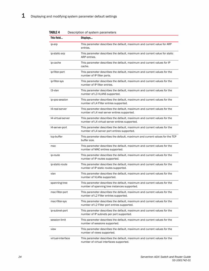
Displaying and modifying system parameter default settings1DRAFT: BROCADE CONFIDENTIAL
TABLE 4 Description of system parameters
This field... Displays...
ip-arp This parameter describes the default, maximum and current value for ARP entries.
ip-static-arp This parameter describes the default, maximum and current value for static ARP entries.
ip-cache This parameter describes the default, maximum and current values for IP cache.
ip-filter-port This parameter describes the default, maximum and current values for the number of IP filter ports.
ip-filter-sys This parameter describes the default, maximum and current values for the number of IP filter entries.
l3-vlan This parameter describes the default, maximum and current values for the number of L3 VLANS supported.
ip-qos-session This parameter describes the default, maximum and current values for the number of L4 Filter entries supported.
l4-real-server This parameter describes the default, maximum and current values for the number of L4 real server entires supported.
l4-virtual-server This parameter describes the default, maximum and current values for the number of L4 virtual server entires supported.
l4-server-port This parameter describes the default, maximum and current values for the number of L4 server port entires supported.
tcp-buffer This parameter describes the default, maximum and current values for the TCP buffer size.
mac This parameter describes the default, maximum and current values for the number of MAC entires supported.
ip-route This parameter describes the default, maximum and current values for the number of IP routes supported.
ip-static-route This parameter describes the default, maximum and current values for the number of IP static routes supported.
vlan This parameter describes the default, maximum and current values for the number of VLANs supported.
spanning-tree This parameter describes the default, maximum and current values for the number of spanning tree instances supported.
mac-filter-port This parameter describes the default, maximum and current values for the number of L2 Filter entries supported.
mac-filter-sys This parameter describes the default, maximum and current values for the number of L2 Filter port entries supported.
ip-subnet-port This parameter describes the default, maximum and current values for the number of IP subnets per port supported.
session-limit This parameter describes the default, maximum and current values for the number of sessions supported.
view This parameter describes the default, maximum and current values for the number of views supported.
virtual-interface This parameter describes the default, maximum and current values for the number of virtual interfaces supported.
24 ServerIron ADX Switch and Router Guide53-1001742-01

Displaying and modifying system parameter default settings 1DRAFT: BROCADE CONFIDENTIAL
To simplify configuration, the command parameter you enter to configure the table is used for the table name. For example, to increase the capacity of the IP route table, enter the following commands.
ServerIron(config)# system-max ip-route 120000ServerIron(config)# write memoryServerIron(config)# exitServerIron# reload
NOTEIf you accidentally enter a value that is not within the valid range of values, the CLI will display the valid range for you.
To increase the number of IP subnet interfaces you can configure on each port on a ServerIron ADX Switch from 24 to 64, then increase the total number of IP interfaces you can configure on the device from 256 to 512, enter the following commands.
Syntax: system-max ip-subnet-port <num>
The <num> parameter specifies the maximum number of subnet addresses per port and can be from 1 – 64. The default is 24.
Syntax: system-max subnet-per-system <num>
The <num> parameter specifies the maximum number of subnet addresses for the entire device and can be from 1 – 512. The default is 256.
You can increase the size of the IP route table for static routes by entering the following command.
NetIron(config)# system-max ip-static-route 8192
Syntax: system-max ip-static-route <num>
On most devices, the maximum number of static routes you can define is 4096. On devices running Service Provider software Release 09.1.02, you can have a maximum of 8192 static routes.
ssl-concurrent-comm This parameter describes the default, maximum and current values for the number of SSL concurrent connections supported.
ssl-cert-size This parameter describes the default, maximum and current values for the SSL certificate file size.
ssl-v2-concurrrent-conn
This parameter describes the default, maximum and current values for the number of SSL v2 concurrent connections supported.
TABLE 4 Description of system parameters (Continued)
This field... Displays...
ServerIron(config)# system-max ip-subnet-port 64ServerIron(config)# write memoryServerIron(config)# exitServerIron# reload
ServerIron(config)# system-max ip-subnet-port 512ServerIron(config)# write memoryServerIron(config)# exitServerIron# reload
ServerIron ADX Switch and Router Guide 2553-1001742-01

Using the temperature sensor1DRAFT: BROCADE CONFIDENTIAL
NOTEYou must reload the software for the change to take effect.
Using the temperature sensorThe temperature sensor generates a Syslog message and SNMP trap if the temperature exceeds a specified warning level or shutdown level, and can shut the module down if the temperature exceeds the safe threshold. You can use the CLI or Web management interface to display the temperature and to change the warning and shutdown temperature levels. The software reads the temperature sensor according to the chassis poll time, which is 60 seconds by default.
If the temperature equals or exceeds the shutdown temperature for five consecutive polls of the temperature by the software, the software shuts down the module to prevent damage.
You can display the temperature of the module. You also can change the warning and shutdown temperatures and the chassis poll time.
Displaying the temperatureBy default, the software polls the temperature sensor on the module every 60 seconds to get the current temperature. This poll rate is controlled by the chassis poll time, which also controls how often the software polls other system components. You can display the temperature of the module using either of the following methods.
To display the temperature of a module, enter the following command at any level of the CLI.
Syntax: show chassis
Displaying temperature messagesThe software sends a Syslog message and an SNMP trap if the temperature crosses the warning or shutdown thresholds. These messages are written to both the static and dynamic log files. The following methods describe how to view the system log files on the device. If you have configured the device to use a Syslog server or SNMP trap receiver, see the documentation for the server or receiver.
To display the system log, enter the following command at any CLI level.
ServerIron> show chassispower supply 1 not presentpower supply 2 not presentpower supply 3 okpower supply 4 not presentpower supply 1 to 4 from bottom to topfan 1 okfan 2 badfan 3 okfan 4 okCurrent temperature : 34.5 C degreesWarning level : 45 C degrees, shutdown level : 55 C degrees
26 ServerIron ADX Switch and Router Guide53-1001742-01

Using the temperature sensor 1DRAFT: BROCADE CONFIDENTIAL
Changing temperature warning and shutdown levelsThe default warning temperature is 45.0 C degrees. The default shutdown temperature is 55.0 C degrees. You can change the warning and shutdown temperatures using the following commands. The valid range for each value is 0 – 125 C degrees.
NOTEYou cannot set the warning temperature to a value higher than the shutdown temperature.
To change the temperature at which the module sends a warning, enter a command such as the following at the Privileged EXEC level of the CLI.
ServerIron# temperature warning 47
Syntax: temperature warning <value>
The <value> can be 0 – 125.
To change the shutdown temperature, enter a command such as the following at Privileged EXEC level of the CLI.
ServerIron# temperature shutdown 57
Syntax: temperature shutdown <value>
The <value> can be 0 – 125.
Changing the chassis polling intervalThe software reads the temperature sensor and polls other hardware sensors according to the value set for the chassis poll time, which is 60 seconds by default. You can change chassis poll time using the CLI.
To change the chassis poll time, enter a command such as the following at the global CONFIG level of the CLI.
ServerIron(config)# chassis poll-time 200
Syntax: chassis poll-time <value>
ServerIron# show logSyslog logging: enabled (0 messages dropped, 0 flushes, 0 overruns)Buffer logging: level ACDMEINW, 8 messages loggedlevel code: A=alert C=critical D=debugging M=emergency E=errorI=informational N=notification W=warning
Static Log Buffer:
Dynamic Log Buffer (50 entries):
at 0 days 0 hours 2 minutes 0 seconds, level alertTemperature 48.0 C degrees, warning level 45.0 C degrees, shutdown level 55.0 C degrees
at 0 days 0 hours 1 minutes 0 seconds, level alertTemperature 50.0 C degrees, warning level 45.0 C degrees, shutdown level 55.0 Cdegrees
ServerIron ADX Switch and Router Guide 2753-1001742-01

Assigning a mirror port and monitor ports1DRAFT: BROCADE CONFIDENTIAL
The <value> can be 0 – 65535.
Assigning a mirror port and monitor portsYou can monitor traffic on Brocade ports by configuring another port to “mirror” the traffic on the ports you want to monitor. By attaching a protocol analyzer to the mirror port, you can observe the traffic on the monitored ports.
Monitoring traffic on a port is a two-step process:
• Enable a port to act as the mirror port. This is the port to which you connect your protocol analyzer.
• Enable monitoring on the ports you want to monitor.
You can monitor input traffic, output traffic, or both. Any port can operate as a mirror port and you can configure more than one mirror port. You can configure the mirror ports on different modules and you can configure more than one mirror port on the same module.
Each mirror port can have its own set of monitored ports. For example, you can configure ports 1/1 and 5/1 as mirror ports, and monitor ports 1/2 – 1/8 on port 1/1 and ports 5/2 – 5/8 on port 5/1. The mirror port and monitored ports also can be on different slots.
ServerIron ADX monitoring limitationsThe following are limitations when using monitoring with a ServerIron ADX switch:
• You cannot configure more that two active mirror ports on a single interface Module.
• ServerIron ADX does not support mirroring a single port to more than one port.
Monitoring an individual trunk portBy default, when you monitor the primary port in a trunk group, aggregated traffic for all the ports in the trunk group is copied to the mirror port. You can configure the device to monitor individual ports in a trunk group. You can monitor the primary port or a secondary port individually.
NOTEIn the current release, you can use only one mirror port for each monitored trunk port.
To monitor traffic on an individual port in a trunk group, enter commands such as the following.
ServerIron(config)# mirror ethernet 2/1ServerIron(config)# trunk switch ethernet 4/1 to 4/8 ServerIron(config-trunk-4/1-4/8)# config-trunk-indServerIron(config-trunk-4/1-4/8)# monitor ethe-port-monitored 4/5 ethernet 2/1 in
Syntax: [no] config-trunk-ind
Syntax: [no] monitor ethe-port-monitored <portnum> | named-port-monitored <portname> ethernet | out | both
The config-trunk-ind command enables configuration of individual ports in the trunk group. You need to enter the config-trunk-ind command only once in a trunk group. After you enter the command, all applicable port configuration commands apply to individual ports only.
28 ServerIron ADX Switch and Router Guide53-1001742-01
Assigning a mirror port and monitor ports 1DRAFT: BROCADE CONFIDENTIAL
NOTEIf you enter no config-trunk-ind, all port configuration commands are removed from the individual ports and the configuration of the primary port is applied to all the ports. Also, once you enter the no config-trunk-ind command, the enable, disable, and monitor commands are valid only on the primary port and apply to the entire trunk group.
The monitor ethe-port-monitored command in this example enables monitoring of the inbound traffic on port 4/5:
• The ethe-port-monitored <portnum> | named-port-monitored <portname> parameter specifies the trunk port you want to monitor. Use ethe-port-monitored <portnum> to specify a port number. Use named-port-monitored <portname> to specify a trunk port name.
• The ethernet | pos <portnum> parameter specifies the port to which the traffic analyzer is attached.
• The in | out | both parameter specifies the traffic direction to be monitored.
Monitoring 802.3ad aggregate linksYou can monitor 802.3ad aggregate links, as well as individual ports within 802.3ad aggregate links.
NOTEThe terms 802.3ad aggregate link and dynamic trunk group are used interchangeably in this section and mean the same thing.
Configuration note
Consider the following:
• This feature cannot be saved to memory and will need to be reconfigured everytime the box is reloaded.
• This feature is supported on any port that can be configured with 802.3ad link aggregation.
Configuring port monitoring on 802.3ad aggregate links
By default, when you enable monitoring on the primary port of an 802.3ad aggregate link, the device copies the traffic for all the ports in the dynamic trunk group to the mirror port.
To monitor all of the ports in an 802.3ad aggregate link, enter commands such as the following on the primary port of the dynamic trunk group.
ServerIron(config)# interface e1/1ServerIron(config-if-e100-1/1)# link-aggregate monitor ethernet-port-monitored e 1/1 e 1/10 both
These commands enable monitoring of the entire dynamic trunk group and copy both incoming and outgoing traffic to port 1/10, the assigned mirror port. Note that the mirror port (in this case, port 1/10) must already be configured as a mirror port.
Syntax: link-aggregate monitor ethernet-port-monitored ethernet <monitor slot/port> <mirror slot/port> both | in | out
The <monitor slot/port> parameter specifies the port to monitor.
ServerIron ADX Switch and Router Guide 2953-1001742-01

Assigning a mirror port and monitor ports1DRAFT: BROCADE CONFIDENTIAL
The <mirror slot/port> parameter specifies the port that will receive copies of the monitored port’s traffic.
The both | in | out parameter specifies the traffic direction to monitor. There is no default.
Configuring port monitoring on an individual port in an 802.3ad aggregate link
To monitor traffic on an individual port in a dynamic trunk group, enter commands such as the following.
ServerIron(config)#interface e1/1ServerIron(config-if-e100-1/1)# link-aggregate config-ind-monitorServerIron(config-if-e100-1/1)# link-aggregate monitor ethernet-port-monitored ethernet 1/1 ethernet 1/10 in
Syntax: [no] link-aggregate config-ind-monitor
Syntax: link-aggregate monitor ethernet-port-monitored ethernet <monitor slot/port> <mirror slot/port> in | out | both
The link-aggregate config-ind-monitor command enables configuration of individual ports in the dynamic trunk group. Enter this command only once in a dynamic trunk group configuration. After you enter this command, all applicable port configuration commands apply to individual ports only.
NOTEIf you enter no link-aggregate config-ind-monitor, the device removes all monitor configuration commands from the individual ports and applies the primary port’s configuration to all the ports. Also, once you enter the no link-aggregate config-ind-monitor command, any monitor configuration command you enter thereafter applies to the entire trunk group.
The link-aggregate monitor ethernet-port-monitored ethernet command in this example enables monitoring of inbound traffic on port 1/1.
• The <monitor slot/port> parameter specifies the port to monitor.
• The <mirror slot/port> parameter specifies the port that will receive copies of the monitored port’s traffic.
• The in | out | both parameter specifies the traffic direction to monitor. There is no default.
Displaying the current mirror and monitor port configuration You can display the current port mirroring and monitoring configuration using the following CLI method.
To display the current mirroring and monitoring configuration, enter the following command at any level of the CLI.
Syntax: bb
ServerIron(config)# show monitorMirror Interface: ethernet 4/1Monitored Interfaces:
Both Input Output --------------------------------------------------- ethernet 4/3
30 ServerIron ADX Switch and Router Guide53-1001742-01

Assigning a mirror port and monitor ports 1DRAFT: BROCADE CONFIDENTIAL
This example shows the monitoring and mirroring configuration set up by the commands in the example in the previous section. Port 4/1 is the mirror interface, to which traffic on port 4/3 is copied. In this case, both directions of traffic on the monitored port are mirrored to port 4/1.
If only the incoming traffic is mirrored, the monitored interface is listed under Input. If only the outbound traffic is mirrored, the monitored interface is listed under Output.
ServerIron ADX Switch and Router Guide 3153-1001742-01

Assigning a mirror port and monitor ports1DRAFT: BROCADE CONFIDENTIAL
32 ServerIron ADX Switch and Router Guide53-1001742-01
ServerIron ADX Switch and Router Guide53-1001742-01
DRAFT: BROCADE CONFIDENTIAL
Chapter
2
Configuring Basic Layer 3In this chapter•Configuring basic Layer 3 overview . . . . . . . . . . . . . . . . . . . . . . . . . . . . . . . . 33
•Adding a static IP route . . . . . . . . . . . . . . . . . . . . . . . . . . . . . . . . . . . . . . . . . . 33
•Adding a static ARP entry . . . . . . . . . . . . . . . . . . . . . . . . . . . . . . . . . . . . . . . . 34
•Configuring RIP . . . . . . . . . . . . . . . . . . . . . . . . . . . . . . . . . . . . . . . . . . . . . . . . 35
•Additional features . . . . . . . . . . . . . . . . . . . . . . . . . . . . . . . . . . . . . . . . . . . . . 38
Configuring basic Layer 3 overviewThis chapter describes how to configure static IP and RIP in the Layer 3 software image. The Layer 2 with Layer 3 software image contains all the system-level features in the Layer 2 images, along with the following:
• Static IP routes
• RIPv1 and RIPv2
• Routing between directly connected subnets
• RIP advertisements of the directly connected subnets
The procedures in this chapter describe how to perform the following tasks:
• Add a static IP route.
• Add a static entry to the ARP table.
• Configure RIP.
Adding a static IP routeTo add a static IP route, enter a command such as the following at the global CONFIG level of the CLI.
ServerIron(config)# ip route 209.157.2.0 255.255.255.0 192.168.2.1
This commands adds a static IP route to the 209.157.2.x/24 subnet.
Syntax: [no] ip route <dest-ip-addr> <dest-mask> <next-hop-ip-addr> [<metric>]
or
Syntax: [no] ip route <dest-ip-addr>/<mask-bits> <next-hop-ip-addr> [<metric>]
33

Disabling Layer 2 switching2DRAFT: BROCADE CONFIDENTIAL
The <dest-ip-addr> is the route’s destination. The <dest-mask> is the network mask for the route’s destination IP address. Alternatively, you can specify the network mask information by entering a forward slash followed by the number of bits in the network mask. For example, you can enter 192.0.0.0 255.255.255.0 as 192.0.0.0/.24. To configure a default route, enter 0.0.0.0 for <dest-ip-addr> and 0.0.0.0 for <dest-mask> (or 0 for the <mask-bits> if you specify the address in CIDR format). Specify the IP address of the default gateway using the <next-hop-ip-addr> parameter.
The <next-hop-ip-addr> is the IP address of the next-hop router (gateway) for the route.
The <metric> parameter specifies the cost of the route and can be a number from 1 – 16. The default is 1. The metric is used by RIP. If you do not enable RIP, the metric is not used.
Disabling Layer 2 switchingThe Route Only feature allows a port to be configured in a mode that only packets meant for Layer-3 forwarding are forwarded by the system. All Layer-2 traffic arriving at the port that would have been switched is discarded. Packets destined to the switch itself are still sent to CPU for processing. Route Only can also be configured globally which applies the Route Only feature to all ports in the system.
You can apply Route Only globally as shown in the following.
ServerIron(config)# route-only
You can apply Route Only for a specific interface as shown in the following:
ServerIron(config)# interface ethernet 3ServerIron(config-if-e1000-3)# route-only
Syntax: [no] route-only
The route-only command is not supported on a VE interface.
NOTEAs a best practice, we recommend you do not put route-only on interfaces where servers are connected.
Adding a static ARP entryStatic entries are useful in cases where you want to pre-configure an entry for a device that is not connected to the ServerIron ADX, or you want to prevent a particular entry from aging out. The software removes a dynamic entry from the ARP cache if the ARP aging interval expires before the entry is refreshed. Static entries do not age out, regardless of whether the ServerIron ADX receives an ARP request from the device that has the entry’s address. The software places a static ARP entry into the ARP cache as soon as you create the entry.
To add a static ARP entry, enter a command such as the following at the global CONFIG level of the CLI.
ServerIron(config)# arp 1 209.157.22.3 aaaa.bbbb.cccc ethernet 3
This command adds a static ARP entry that maps IP address 209.157.22.3 to MAC address aaaa.bbbb.cccc. The entry is for a MAC address connected to ServerIron ADX port 3.
34 ServerIron ADX Switch and Router Guide53-1001742-01
Configuring RIP 2DRAFT: BROCADE CONFIDENTIAL
Syntax: [no] arp <num> <ip-addr> <mac-addr> ethernet <portnum>
The <num> parameter specifies the entry number. You can specify a number from 1 up to the maximum number of static entries allowed on the device. You can allocate more memory to increase this amount. To do so, enter the system-max ip-static-arp <num> command at the global CONFIG level of the CLI.
The <ip-addr> command specifies the IP address of the device that has the MAC address of the entry.
The <mac-addr> parameter specifies the MAC address of the entry.
The ethernet <portnum> command specifies the port number attached to the device that has the MAC address of the entry.
NOTEThe clear arp command clears learned ARP entries but does not remove any static ARP entries.
Configuring RIPRIP is disabled by default. If you want the ServerIron ADX to use RIP you must enable the protocol globally, then enable RIP on individual ports. When you enable RIP on a port, you also must specify the version (version 1 only, version 2 only, or version 1 compatible with version 2).
Optionally, you also can set or change the following parameters:
• Route redistribution – You can enable the software to redistribute static routes from the IP route table into RIP. Redistribution is disabled by default.
• Learning of default routes – The default is disabled.
• Loop prevention (split horizon or poison reverse) – The default is poison reverse.
Enabling RIPRIP is disabled by default. To enable it, use the following CLI method. You must enable the protocol both globally and on the ports on which you want to use RIP.
To enable RIP globally, enter the following command.
ServerIron(config)# router rip
Syntax: [no] router rip
To enable RIP on a port and specify the RIP version, enter commands such as the following.
ServerIron(config-rip-router)# interface ethernet 1ServerIron(config-if-1)# ip rip v1-only
This command changes the CLI to the configuration level for port 1and enables RIP version 1 on the interface. You must specify the version.
Syntax: interface ethernet <portnum>
Syntax: [no] ip rip v1-only | v1-compatible-v2 | v2-only
ServerIron ADX Switch and Router Guide 3553-1001742-01

Configuring RIP2DRAFT: BROCADE CONFIDENTIAL
Enabling redistribution of IP static routes into RIPBy default, the software does not redistribute the IP static routes in the route table into RIP. To configure redistribution, perform the following tasks:
• Configure redistribution filters (optional). You can configure filters to permit or deny redistribution for a route based on the route’s metric. You also can configure a filter to change the metric. You can configure up to 64 redistribution filters. The software uses the filters in ascending numerical order and immediately takes the action specified by the filter. Thus, if filter 1 denies redistribution of a given route, the software does not redistribute the route, regardless of whether a filter with a higher ID permits redistribution of that route.
NOTEThe default redistribution action is permit, even after you configure and apply a permit or deny filter. To deny redistribution of specific routes, you must configure a deny filter.
NOTEThe option to set the metric is not applicable to static routes.
• Enable redistribution.
NOTEIf you plan to configure redistribution filters, do not enable redistribution until you have configured the filters.
When you enable redistribution, all IP static routes are redistributed by default. If you want to deny certain routes from being redistributed into RIP, configure deny filters for those routes before you enable redistribution. You can configure up to 64 RIP redistribution filters. They are applied in ascending numerical order.
NOTEThe default redistribution action is still permit, even after you configure and apply redistribution filters to the port. If you want to tightly control redistribution, apply a filter to deny all routes as the last filter (filter ID 64), then apply filters with lower filter IDs to allow specific routes.
To configure a redistribution filter, enter a command such as the following.
ServerIron(config-rip-router)# deny redistribute 1 static address 207.92.0.0 255.255.0.0
This command denies redistribution of all 207.92.x.x IP static routes.
Syntax: [no] permit | deny redistribute <filter-num> static address <ip-addr> <ip-mask> [match-metric <value> | set-metric <value>]
The <filter-num> specifies the redistribution filter ID. Specify a number from 1 – 64. The software uses the filters in ascending numerical order. Thus, if filter 1 denies a route from being redistributed, the software does not redistribute that route even if a filter with a higher ID permits redistribution of the route.
The address <ip-addr> <ip-mask> parameters apply redistribution to the specified network and subnet address. Use 0 to specify “any”. For example, “207.92.0.0 255.255.0.0“ means “any 207.92.x.x subnet”. However, to specify any subnet (all subnets match the filter), enter “address 255.255.255.255 255.255.255.255”.
36 ServerIron ADX Switch and Router Guide53-1001742-01

Configuring RIP 2DRAFT: BROCADE CONFIDENTIAL
The match-metric <value> parameter applies redistribution to those routes with a specific metric value; possible values are from 1 – 15.
The set-metric <value> parameter sets the RIP metric value that will be applied to the routes imported into RIP.
NOTEThe set-metric parameter does not apply to static routes.
The following command denies redistribution of a 207.92.x.x IP static route only if the route’s metric is 5.
ServerIron(config-rip-router)# deny redistribute 2 static address 207.92.0.0 255.255.0.0 match-metric 5
The following commands deny redistribution of all routes except routes for 10.10.10.x and 20.20.20.x.
ServerIron(config-rip-router)# deny redistribute 64 static address 255.255.255.255 255.255.255.255ServerIron(config-rip-router)# permit redistribute 1 static address 10.10.10.0 255.255.255.0ServerIron(config-rip-router)# permit redistribute 2 static address 20.20.20.0 255.255.255.0
Enabling redistributionAfter you configure redistribution parameters, you need to enable redistribution.
To enable RIP redistribution, enter the following command.
ServerIron(config-rip-router)# redistribution
Syntax: [no] redistribution
Enabling learning of default routesBy default, the software does not learn RIP default routes.
To enable learning of default RIP routes, enter commands such as the following.
ServerIron(config)# interface ethernet 1ServerIron(config-if-1)# ip rip learn-default
Syntax: interface ethernet <portnum>
Syntax: [no] ip rip learn-default
Changing the route loop prevention methodRIP can use the following methods to prevent routing loops:
• Split horizon – The ServerIron ADX does not advertise a route on the same interface as the one on which the ServerIron ADX learned the route.
• Poison reverse – The ServerIron ADX assigns a cost of 16 (“infinite” or “unreachable”) to a route before advertising it on the same interface as the one on which the ServerIron ADX learned the route. This is the default.
ServerIron ADX Switch and Router Guide 3753-1001742-01

Additional features2DRAFT: BROCADE CONFIDENTIAL
NOTEThese methods are in addition to RIP’s maximum valid route cost of 15.
To enable split horizon, enter commands such as the following.
ServerIron(config)# interface ethernet 1ServerIron(config-if-1)# no ip rip poison-reverse
Syntax: [no] ip rip poison-reverse
Additional featuresFor information about the other IP configuration commands in the ServerIron ADX router image,refer to “Configuring IP” on page 219.
38 ServerIron ADX Switch and Router Guide53-1001742-01
ServerIron ADX Switch and Router Guide53-1001742-01
DRAFT: BROCADE CONFIDENTIAL
Chapter
3
Configuring Trunk Groups and Dynamic Link AggregationIn this chapter•Configuring trunk groups. . . . . . . . . . . . . . . . . . . . . . . . . . . . . . . . . . . . . . . . . 39
•Dynamic link aggregation . . . . . . . . . . . . . . . . . . . . . . . . . . . . . . . . . . . . . . . . 49
This chapter describes how to configure trunk groups and 802.3ad link aggregation.
• Trunk groups are manually-configured aggregate links containing multiple ports.
• 802.3ad link aggregation is a protocol that dynamically creates and manages trunk groups.
NOTEYou can use both types of trunking on the same device. However, you can use only one type of trunking for a given port. For example, you can configure port 1/1 as a member of a static trunk group or you can enable 802.3ad link aggregation on the port, but you cannot do both.
Configuring trunk groupsThe Trunk Group feature allows you to manually configure multiple high-speed load-sharing links between two Brocade Layer 2 Switches or Layer 3 Switches or between a Brocade Layer 2 Switch and Layer 3 Switch and a server. You can configure up to 8 ports as a trunk group, supporting transfer rates of up to 80 Gbps of bi-directional traffic.
In addition to enabling load sharing of traffic, trunk groups provide redundant, alternate paths for traffic if any of the segments fail.
Figure 1 shows an example of a configuration that uses trunk groups.
39

Configuring trunk groups3DRAFT: BROCADE CONFIDENTIAL
FIGURE 1 Trunk Group application within a Brocade ServerIron ADX
NOTEThe ports in a trunk group make a single logical link. Therefore, all the ports in a trunk group must be connected to the same device at the other end.
Trunk group connectivity to a serverTo support termination of a trunk group, the server must have either multiple network interface cards (NICs) or either a dual or quad interface card installed. The trunk server is designated as a server with multiple adapters or a single adapter with multiple ports that share the same MAC and IP address. Figure 2 shows an example of a trunk group between a server and a ServerIron ADX.
. . .GigabitBackbone
TrunkGroup
Server
ADX1SwitchingRouter
Power UsersDedicated 100 Mbps
ADX2Switch
ADX3SwitchingRouter
TrunkGroup
40 ServerIron ADX Switch and Router Guide53-1001742-01
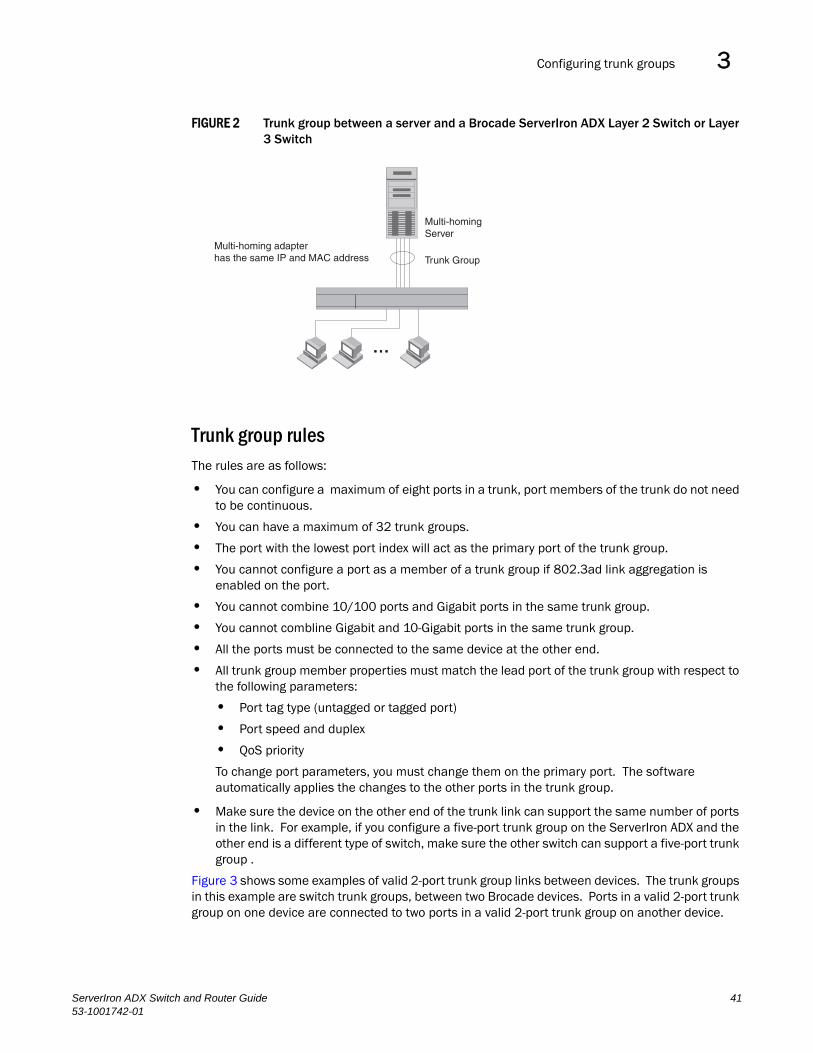
Configuring trunk groups 3DRAFT: BROCADE CONFIDENTIAL
FIGURE 2 Trunk group between a server and a Brocade ServerIron ADX Layer 2 Switch or Layer 3 Switch
Trunk group rulesThe rules are as follows:
• You can configure a maximum of eight ports in a trunk, port members of the trunk do not need to be continuous.
• You can have a maximum of 32 trunk groups.
• The port with the lowest port index will act as the primary port of the trunk group.
• You cannot configure a port as a member of a trunk group if 802.3ad link aggregation is enabled on the port.
• You cannot combine 10/100 ports and Gigabit ports in the same trunk group.
• You cannot combline Gigabit and 10-Gigabit ports in the same trunk group.
• All the ports must be connected to the same device at the other end.
• All trunk group member properties must match the lead port of the trunk group with respect to the following parameters:
• Port tag type (untagged or tagged port)
• Port speed and duplex
• QoS priority
To change port parameters, you must change them on the primary port. The software automatically applies the changes to the other ports in the trunk group.
• Make sure the device on the other end of the trunk link can support the same number of ports in the link. For example, if you configure a five-port trunk group on the ServerIron ADX and the other end is a different type of switch, make sure the other switch can support a five-port trunk group .
Figure 3 shows some examples of valid 2-port trunk group links between devices. The trunk groups in this example are switch trunk groups, between two Brocade devices. Ports in a valid 2-port trunk group on one device are connected to two ports in a valid 2-port trunk group on another device.
Multi-homing adapterhas the same IP and MAC address
Multi-homingServer
Tr unk Group......
Multi-homing adapterhas the same IP and MAC address
Multi-homingServer
Tr unk Group
ServerIron ADX Switch and Router Guide 4153-1001742-01

Configuring trunk groups3DRAFT: BROCADE CONFIDENTIAL
FIGURE 3 Examples of 2-port trunk groups
Additional trunk group rules for multi-slot trunk groups
Consider the following:
• Multi-slot trunk groups are supported only on Chassis devices.
• You can configure a multi-slot trunk group on Gigabit Ethernet Interface modules or 10 Gigabit Ethernet Interface modules.
• You can configure a maximum of eight ports in the trunk group.
• When you specify the ports in the trunk group, you must specify them in ascending numerical order, beginning with the primary port. For example, to specify a group containing ports 1/1 – 1/4 and 3/1 – 3/4, you must specify them in the order shown. You cannot specify 3/1 – 3/4 first.
• Port configuration for each trunk group is based on the configuration of the primary port. To change port parameters, you must change them on the primary port. The software automatically applies the changes to the other ports in the trunk group.
Trunk group load sharingWhen you configure a trunk group, you specify whether the trunk group is a “switch” trunk group or a “server” trunk group:
• Switch trunk group – Use this type of trunk group to load balance traffic based on destination MAC addresses.
• Server trunk group – Use this type of trunk group to load balance traffic based on source IP and destination IP addresses.
Traffic distribution among trunk groupsTraffic distribution among trunk groups is described in Table 5. Traffic distribution among trunk groups is the same for switch and router code. LACP trunks default to trunk switch behavior.
TABLE 5 Traffic distribution among trunk groups
Trunk Type Traffic Type Traffic distributed based on
Trunk Switch Pass-through Destination MAC, VLAN, EtherType, Source Module and Port ID
Trunk Switch SLB Destination MAC
Trunk Server Pass-through. Source IP, Destination IP, Source Port and Destination Port
Trunk Server SLB Source IP and Destination IP
42 ServerIron ADX Switch and Router Guide53-1001742-01

Configuring trunk groups 3DRAFT: BROCADE CONFIDENTIAL
NOTEMulticast/broadcast traffic is not load balanced. Management generated traffic is not load balanced. These traffic types select the first active port in the trunk.
Configuring a trunk group1. Disconnect the cables from those ports on both systems that will be connected by the trunk
group. Do not configure the trunk groups with the cables connected.
NOTEIf you connect the cables before configuring the trunk groups and then rebooting, the traffic on the ports can create a spanning tree loop.
2. Configure the trunk group on one of the two Layer 2 Switches or Layer 3 Switches involved in the configuration.
3. Save the configuration changes to the startup-config file.
4. Dynamically place the new trunk configuration into effect by entering the trunk deploy command at the global CONFIG level of the CLI.
5. If the device at the other end of the trunk group is another Layer 2 Switch or Layer 3 Switch, repeat Steps 2 – 4 for the other device.
6. When the trunk groups on both devices are operational, reconnect the cables to those ports that are now configured as trunk groups, starting with the first port (lead port) of each trunk group.
7. To verify the link is operational, use the show trunk command.
Example 1: Configuring the trunk groups shown in Figure 1
To configure the trunk groups shown in Figure 1, enter the following commands.
To configure the trunk group link between ServerIron ADX switch routers, enter the following commands.
NOTEThe text shown in italics in the CLI example below shows messages echoed to the screen in answer to the CLI commands entered.
ServerIronADX1(config)# trunk server e 5 to 8Trunk will be created in next trunk deploy.ServerIronADX1(config)# write memoryWrite startup-config in progress..Write startup-config done.ServerIronADX1(config)# trunk deploy
To configure the trunk group link between a ServerIron ADX and the server:ServerIronADX2(config)# trunk server e 2 to 4Trunk will be created in next trunk deploy.ServerIronADX2(config)# write memoryWrite startup-config in progress..Write startup-config done.ServerIronADX2(config)# trunk deployTrunk will be created in next trunk deploy.
ServerIron ADX Switch and Router Guide 4353-1001742-01

Configuring trunk groups3DRAFT: BROCADE CONFIDENTIAL
ServerIronADX3(config)# trunk switch ethernet 17 to 18ServerIronADX(config)# write memoryWrite startup-config in progress..Write startup-config done.ServerIronADX3(config)# trunk deploy
Example 2: Configuring a trunk group that spans multiple Gigabit Ethernet modules in a chassis device
To configure a trunk group consisting of two groups of ports, 1/1 – 1/4 on module 1 and 4/5 – 4/8 on module 4, enter the following commands.
ServerIronADX(config)# trunk server ethernet 1/1 to 1/4 ethernet 4/5 to 4/8ServerIronADX(config-trunk-1/1-4/8)# write memoryServerIronADX(config-trunk-1/1-4/8)# exitServerIronADX(config)# trunk deploy
NOTEThe trunk deploy command dynamically places trunk configuration changes into effect, without a software reload.
Syntax: [no] trunk [server | switch] ethernet | to <portnum> ethernet <portnum> to <portnum>
Syntax: trunk deploy
The server | switch parameter specifies whether the traffic is expected to be load balanced based on source IP and destination IP addresses or destination MAC addresses. This parameter affects the type of load balancing performed by the Brocade device. Refer to “Trunk group load sharing” on page 42. The default is switch. Note that this parameter is not supported on the FES X-Series.
Each ethernet parameter introduces a port group.
The <portnum> to <portnum> parameters specify a port group. After you enter this command, the first port of the first port group specified (which must be the group with the lower port numbers) becomes the primary port for the entire trunk group.
To configure a trunk group consisting of two groups of two ports each, enter commands such as the following.
ServerIronADX(config)# trunk server ethernet 1/1 to 1/2 ethernet 3/3 to 3/4ServerIronADX(config)# write memoryServerIronADX(config)# trunk deploy
FIGURE 4 4-port Trunk Group
Additional trunking optionsThe CLI contains commands for doing the following:
Device 1 Device 2
1/1
1/2
2/1
2/2
1/1
1/2
2/1
2/2
44 ServerIron ADX Switch and Router Guide53-1001742-01
Configuring trunk groups 3DRAFT: BROCADE CONFIDENTIAL
• Naming a trunk port
• Disabling or re-enabling a trunk port
• Deleting a trunk group
Naming a trunk port
To name an individual port in a trunk group, enter a command such as the following at the trunk group configuration level.
ServerIronADX(config-trunk-4/1-4/4)# port-name customer1 ethernet 4/2
Syntax: [no] port-name <text> ethernet <portnum>
The <text> parameter specifies the port name.
This command assigns the name “customer1” to port 4/2 in the trunk group consisting of ports 4/1 – 4/4.
Disabling or re-enabling a trunk port
You can disable or re-enable individual ports in a trunk group. To disable an individual port in a trunk group, enter commands such as the following at the trunk group configuration level.
ServerIronADX(config-trunk-4/1-4/4)# config-trunk-indServerIronADX(config-trunk-4/1-4/4)# disable ethernet 4/2
Syntax: [no] config-trunk-ind
Syntax: [no] disable ethernet | pos <portnum>
The config-trunk-ind command enables configuration of individual ports in the trunk group. If you do not use this command, the disable command will be valid only for the primary port in the trunk group and will disable all ports in the trunk group. You need to enter the config-trunk-ind command only once in a trunk group. After you enter the command, all applicable port configuration commands apply to individual ports only.
NOTEIf you enter no config-trunk-ind, all port configuration commands are removed from the individual ports and the configuration of the primary port is applied to all the ports. Also, once you enter the no config-trunk-ind command, the enable, disable, and monitor commands are valid only on the primary port and apply to the entire trunk group.
The disable command disables the port. The states of other ports in the trunk group are not affected.
If you have configured a name for the trunk port, you can specify the port name, as shown in the following example.
ServerIronADX(config-trunk-4/1-4/4)# config-trunk-indServerIronADX(config-trunk-4/1-4/4)# disable customer1
Syntax: disable <portname>
To enable an individual port in a trunk group, enter commands such as the following at the trunk group configuration level.
ServerIronADX(config-trunk-4/1-4/4)# config-trunk-indServerIronADX(config-trunk-4/1-4/4)# enable ethernet 4/2
ServerIron ADX Switch and Router Guide 4553-1001742-01
Configuring trunk groups3DRAFT: BROCADE CONFIDENTIAL
Syntax: enable ethernet <portnum>
Syntax: enable <portname>
Disabling or re-enabling a range or list of trunk portsTo disable a range of ports in a trunk group, enter commands such as the following.
ServerIronADX(config)# trunk switch ethernet 2/1 to 2/8ServerIronADX(config-trunk-2/1-2/8)# config-trunk-indServerIronADX(config-trunk-2/1-2/8)# disable ethernet 2/2 to 2/5
This command disables ports 2/2 – 2/5 in trunk group 2/1 – 2/8.
To disable a list of ports, enter a command such as the following.
ServerIronADX(config-trunk-2/1-2/8)# disable ethernet 2/2 ethernet 2/4 ethernet 2/7
This command disables ports 2/2, 2/4, and 2/7 in the trunk group.
You can specify a range and a list on the same command line. For example, to re-enable some trunk ports, enter a command such as the following.
ServerIronADX(config-trunk-2/1-2/8)# enable ethernet 2/2 to 2/5 ethernet 2/7
Syntax: [no] disable ethernet <portnum> [to <portnum> | ethernet <portnum>]
Syntax: [no] enable ethernet <portnum> [to <portnum> | ethernet <portnum>]
The to <portnum> parameter indicates that you are specifying a range. Specify the lower port number in the range first, then to, then the higher port number in the range.
The ethernet <portnum> parameter specifies an individual port. You can enter this parameter multiple times to specify a list, as shown in the examples above. You cannot specify Ethernet and POS ports on the same command line.
Deleting a trunk group
To delete a trunk group, use “no” in front of the command you used to create the trunk group. For example, to remove one of the trunk groups configured in the examples above, enter the following command.
ServerIronADX(config)# no trunk server ethernet 1/1 to 1/2 ethernet 3/3 to 3/4
Syntax: no trunk [switch |server] ethernet <portnum> to <portnum>
Displaying trunk group configuration informationTo display configuration information for the trunk groups configured on the Layer 3 Switch, use one of the following methods. Each method displays information for configured trunk groups and operational trunk groups. A configured trunk group is one that has been configured in the software but has not been placed into operation by a reset/reboot or using the trunk deploy command. An operational trunk group is one that has been placed into operation by a reset/reboot or using the trunk deploy command.
Enter the following command at any CLI level.
46 ServerIron ADX Switch and Router Guide53-1001742-01

Configuring trunk groups 3DRAFT: BROCADE CONFIDENTIAL
Syntax: show trunk [ethernet <portnum> to <portnum>]
The following table describes the information displayed by the show trunk command.
To display trunk group information for specific ports, enter a command such as the following.
TABLE 6 CLI trunk group information
This field... Displays...
Trunk The trunk group number. The software numbers the groups in the display to make the display easy to use.
Type The type of trunk group, which can be one of the following:• Server – The trunk group is expected to load balance the traffic based on
Source IP and Destination IP.• Switch – The trunk group is expected to load balance the traffic based on
destination MAC address.
Ports The ports in the trunk group.
Duplex The mode of the port, which can be one of the following:• None – The link on the primary trunk port is down. • Full – The primary port is running in full-duplex.• Half – The primary port is running in half-duplex.
NOTE: This field and the following fields apply only to operational trunk groups.
Speed The speed set for the port. The value can be one of the following:• None – The link on the primary trunk port is down.• 10 – The port speed is 10 Mbps. • 100 – The port speed is 100 Mbps.• IG – The port speed is 1000 Mbps.
Tag Indicates whether the ports have 802.1q VLAN tagging. The value can be Yes or No.
Priority Indicates the Quality of Service (QoS) priority of the ports. The priority can be a value from 0 – 7.
ServerIronADX(config)# show trunkConfigured trunks:Trunk Type Ports 1 Server 1/1 1/2 1/3 1/4 2/1 2/2 2/3 2/4Operational trunks:Trunk Type Ports Duplex Speed Tag Priority 1 Server 1/1 1/2 1/3 1/4 2/1 2/2 2/3 2/4 None None No level0
ServerIron ADX Switch and Router Guide 4753-1001742-01

Configuring trunk groups3DRAFT: BROCADE CONFIDENTIAL
The display is divided into sections for configured trunks and operational trunks. A configured trunk group is one that has not been activated yet.
Table 7 describes the information displayed by the show trunk command.
TABLE 7 CLI trunk group information
This field... Displays...
Trunk ID The trunk group number. The software numbers the groups in the display to make the display easy to use.
Type The type of trunk group, which can be one of the following:• Server – The trunk group is expected to load balance the traffic based on
Source IP and Destination IP.• Switch – The trunk group is expected to load balance the traffic based on
destination MAC address.
Duplex The mode of the port, which can be one of the following:• None – The link on the primary trunk port is down. • Full – The primary port is running in full-duplex.• Half – The primary port is running in half-duplex.
NOTE: This field and the following fields apply only to operational trunk groups.
ServerIronADX(config)# show trunk ethernet 1/1 to 1/8
Configured trunks:
Trunk ID: 1Type: SwitchPorts_Configured: 8Primary Port Monitored: Jointly
Ports 1/1 1/2 1/3 1/4 1/5 1/6 1/7 1/8Port Names none none none none none longna test nonePort_Status enable enable enable enable disable disable enable enableMonitor on on off on off off off offMirror Port 3/3 3/4 N/A 3/5 N/A N/A N/A N/AMonitor Dir both in N/A out N/A N/A N/A N/A
Operational trunks:
Trunk ID: 1Type: SwitchDuplex: FullSpeed: 1GTag: NoPriority: level0Active Ports: 6
Ports 1/1 1/2 1/3 1/4 1/5 1/6 1/7 1/8Link_Status active active active active down down active activeLACP_Status ready ready ready expired down down ready readyLoad Sharing Mac Address 3 2 2 2 0 0 6 1 IP 0 0 0 0 0 0 0 0 IPX 0 2 1 0 0 0 0 1 Apple Talk 1 2 0 4 0 0 0 3 Multicast 4 2 5 2 0 0 2 3
48 ServerIron ADX Switch and Router Guide53-1001742-01

Dynamic link aggregation 3DRAFT: BROCADE CONFIDENTIAL
Dynamic link aggregationThe software supports the IEEE 802.3ad standard for link aggregation. This standard describes the Link Aggregation Control Protocol (LACP), a mechanism for allowing ports on both sides of a redundant link to configure themselves into a trunk link (aggregate link), without the need for manual configuration of the ports into trunk groups.
When you enable link aggregation on a group of Brocade ports, the Brocade ports can negotiate with the ports at the remote ends of the links to establish trunk groups.
Usage notesConsider the following:
• You cannot use 802.3ad link aggregation on a port configured as a member of a static trunk group.
• When the feature dynamically adds or changes a trunk group, the show trunk command displays the trunk as both configured and active. However, the show running-config or write terminal command does not contain a trunk command defining the new or changed trunk group.
Speed The speed set for the port. The value can be one of the following:• None – The link on the primary trunk port is down.• 10 – The port speed is 10 Mbps. • 100 – The port speed is 100 Mbps.• IG – The port speed is 1000 Mbps.
Tag Indicates whether the ports have 802.1q VLAN tagging. The value can be Yes or No.
Priority Indicates the Quality of Service (QoS) priority of the ports. The priority can be a value from 0 – 7.
Active Ports The number of ports in the trunk group that are currently active.
Ports The ports in the trunk group.
Link_Status The link status or each port in the trunk group.
LACP_Status For more information about this feature, refer to the section “Displaying and determining the status of aggregate links” on page 57:• Ready - The port is functioning normally in the trunk group and is able to
transmit and receive LACP packets.• Expired - The time has expired (as determined by timeout values) and the
port has shut down because the port on the other side of the link has stopped transmitting packets.
• Down - The port’s physical link is down.
Load Sharing The number of traffic flows currently being load balanced on the trunk ports. All traffic exchanged within the flow is forwarded on the same trunk port. For information about trunk load sharing, refer to “Trunk group load sharing” on page 42.
TABLE 7 CLI trunk group information (Continued)
This field... Displays...
ServerIron ADX Switch and Router Guide 4953-1001742-01

Dynamic link aggregation3DRAFT: BROCADE CONFIDENTIAL
• If the feature places a port into a trunk group as a secondary port, all configuration information except information related to link aggregation is removed from the port. For example, if port 1/3 has an IP interface, and the link aggregation feature places port 1/3 into a trunk group consisting of ports 1/1 – 1/4, the IP interface is removed from the port.
• If you use this feature on a ServerIron ADX that is running OSPF, the feature causes these protocols to reset when a dynamic link change occurs. The reset includes ending and restarting neighbor sessions with OSPF peers, and clearing and relearning dynamic route entries and forwarding cache entries. Although the reset causes a brief interruption, the protocols automatically resume normal operation.
• You can enable link aggregation on 802.1q tagged ports (ports that belong to more than one port-based VLAN).
Configuration rulesBrocade ports follow the same configuration rules for dynamically created aggregate links as they do for statically configured trunk groups. Refer to “Trunk group rules” on page 41 and “Trunk group load sharing” on page 42.
Enabling link aggregationBy default, link aggregation is disabled on all ports. To enable link aggregation on a set of ports, enter commands such as the following at the interface configuration level of the CLI.
NOTEConfiguration commands for link aggregation differ depending on whether you are using the default link aggregation key automatically assigned by the software, or if you are assigning a different, unique key. Follow the commands below, according to the type of key you are using. For more information about keys, refer to “Key” on page 52.
Using the default key assigned by the softwareServerIronADX(config)# interface ethernet 1/1ServerIronADX(config-if-e1000-1/1)# link-aggregate activeServerIronADX(config)# interface ethernet 1/2ServerIronADX(config-if-e1000-1/2)# link-aggregate active
The commands in this example enable the active mode of link aggregation on ports 1/1 and 1/2. The ports can send and receive LACPDU messages. Note that these ports will use the default key, since one has not been explicitly configured.
Assigning a unique keyServerIronADX(config)# interface ethernet 1/1ServerIronADX(config-if-e1000-1/1)# link-aggregate configure key 10000ServerIronADX(config-if-e1000-1/1)# link-aggregate activeServerIronADX(config)# interface ethernet 1/2ServerIronADX(config-if-e1000-1/2)# link-aggregate configure key 10000ServerIronADX(config-if-e1000-1/2)# link-aggregate active
The commands in this example assign the key 10000 and enable the active mode of link aggregation on ports 1/1 and 1/2. The ports can send and receive LACPDU messages.
50 ServerIron ADX Switch and Router Guide53-1001742-01

Dynamic link aggregation 3DRAFT: BROCADE CONFIDENTIAL
NOTEAs shown in this example, when configuring a key, it is pertinent that you assign the key prior to enabling link aggregation.
The following commands enable passive link aggregation on ports 1/5 – 1/8.
ServerIronADX(config)# interface ethernet 1/5 to 1/8ServerIronADX(config-mif-1/5-1/8)# link-aggregate passive
The commands in this example enable the passive mode of link aggregation on ports 1/5 – 1/8. These ports wait for the other end of the link to contact them. After this occurs, the ports can send and receive LACPDU messages.
To disable link aggregation on a port, enter a command such as the following.
BigIron(config-if-e1000-1/8)# link-aggregate off
Syntax: [no] link-aggregate active | passive | off
Syntax: [no] link-aggregate configure [system-priority <num>] | [port-priority <num>] | [key <num>] |[type server | switch]
NOTEFor more information about keys, including details about the syntax shown above, refer to “Key” on page 52.
Link aggregation parametersYou can change the settings for the following link aggregation parameters, on an individual port basis:
• System priority
• Port priority
• Link type
• Key
System priority
The system priority specifies the Brocade device’s link aggregation priority relative to the devices at the other ends of the links on which link aggregation is enabled. A higher value indicates a lower priority. You can specify a priority from 0 – 65535. The default is 1.
NOTEIf you are connecting the Brocade device to another vendor’s device and the link aggregation feature is not working, set the system priority on the Brocade device to a lower priority (a higher priority value). In some cases, this change allows the link aggregation feature to operate successfully between the two devices.
ServerIron ADX Switch and Router Guide 5153-1001742-01

Dynamic link aggregation3DRAFT: BROCADE CONFIDENTIAL
Port priority
The port priority determines the active and standby links. When a group of ports is negotiating with a group of ports on another device to establish a trunk group, the Brocade port with the highest priority becomes the default active port. The other ports (with lower priorities) become standby ports in the trunk group. You can specify a priority from 0 – 65535. A higher value indicates a lower priority. The default is 1.
NOTEThis parameter is not supported in the current software release. The primary port in the port group becomes the default active port. The primary port is the lowest-numbered port in a valid trunk-port group.
Link type
The link type specifies load-sharing ability of the dynamic trunk. For more information on load-sharing of trunks, see “Trunk group load sharing” on page 42.
Key
Every port that is 802.3ad-enabled has a key. The key identifies the group of potential trunk ports to which the port belongs. Ports with the same key are called a key group and are eligible to be in the same trunk group.
When you enable link-aggregation on a tagged or untagged port, Brocade’s software assigns a default key to the port. The default key is 1 for al the link aggregation ports.
All ports within an aggregate link must have the same key. However, if the device has ports that are connected to two different devices, and the port groups allow the ports to form into separate aggregate links with the two devices, then each group of ports can have the same key while belonging to separate aggregate links with different devices. Figure 5 on page 53 shows an example.
52 ServerIron ADX Switch and Router Guide53-1001742-01
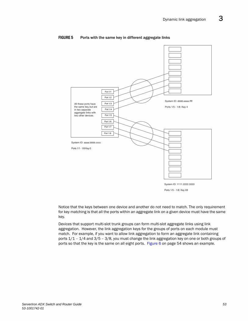
Dynamic link aggregation 3DRAFT: BROCADE CONFIDENTIAL
FIGURE 5 Ports with the same key in different aggregate links
Notice that the keys between one device and another do not need to match. The only requirement for key matching is that all the ports within an aggregate link on a given device must have the same key.
Devices that support multi-slot trunk groups can form multi-slot aggregate links using link aggregation. However, the link aggregation keys for the groups of ports on each module must match. For example, if you want to allow link aggregation to form an aggregate link containing ports 1/1 – 1/4 and 3/5 – 3/8, you must change the link aggregation key on one or both groups of ports so that the key is the same on all eight ports. Figure 6 on page 54 shows an example.
All these ports havethe same key, but arein two separateaggregate links withtwo other devices.
System ID: aaaa.bbbb.cccc
Ports 1/1 - 1/8 Key 0
System ID: 1111.2222.3333
Ports 1/5 - 1/8: Key 69
System ID: dddd.eeee.ffff
Ports 1/5 - 1/8: Key 4
Port 1/1
Port 1/2
Port 1/3
Port 1/4
Port 1/5
Port 1/6
Port 1/7
Port 1/8
ServerIron ADX Switch and Router Guide 5353-1001742-01

Dynamic link aggregation3DRAFT: BROCADE CONFIDENTIAL
FIGURE 6 Multi-slot aggregate link
The ServerIron ADX supports more than one trunk group using link aggregation. However, the link aggregation keys for each trunk group must be unique. For example, if you want to allow ink aggregation to form an aggregate link containing ports 1/1 to 1/4 and another aggregate link containing ports 1/9 to 1/12, you must change the link aggregation key on one or both groups of ports so that the key is not the same for both port groups. This example is illustrated in Figure 7.
FIGURE 7 Multiple trunk groups using link aggregation
NOTEIf there are 8 or fewer ports with the same link aggregation key and some of these ports are down, they will join the trunk created by link aggregation and will become operational once a port comes up and starts receiving LAPCDU.
NOTEIf you change the key for a port group, Brocade recommends that you use the value 10000 or higher, to avoid potential conflicts with dynamically created keys.
System ID: aaaa.bbbb.cccc
Ports 1/1 - 1/4: Key 1Ports 3/5 - 3/8: Key 1
All ports in a multi-slotaggregate link havethe same key.
Port 1/1
Port 1/2
Port 1/3
Port 1/4
Port 3/5
Port 3/6
Port 3/7
Port 3/8
Ports 1/1 - 1/4 Key 10001
Port 1/1
Port 1/2
Port 1/3
Port 1/4
Port 1/9
Port 1/10
Port 1/11
Port 1/12
Ports 1/9 - 1/12 Key 10002
54 ServerIron ADX Switch and Router Guide53-1001742-01

Dynamic link aggregation 3DRAFT: BROCADE CONFIDENTIAL
Dynamic operation of allocation keysTthe ServerIron ADX dynamically changes a port’s key based on changes to the port’s VLAN membership.
When you change a port’s VLAN membership, the device searches through existing key groups for a port with matching port properties. Specifically, it searches for a match on all three of the following properties:
• VLAN ID
• default key
• port tag type (tagged or untagged)
If it finds a match, the port (whose VLAN membership you are changing) gets the matching port’s key. If it does not find a match, the port gets a new key.
NOTEFor multi-slot trunk groups, you must manually configure the keys in the trunk groups to match. For instructions on configuring keys manually, refer to “Configuring keys for ports with link aggregation enabled” on page 57.
How Changing a Port’s VLAN Membership Affects Trunk Groups and Dynamic Keys
When you change a port’s VLAN membership, and the port is currently a member of a trunk group, the following changes occur:
• The ServerIron ADX tears down the existing trunk group.
• All ports in the trunk group get a new key.
• The new key group aggregates into a new trunk group.
When you change a port’s VLAN membership, and the port is not a member of a trunk group, the following changes occur:
• The port gets a new key depending on changes to the port’s VLAN tag type, as follows:
• Tagged to Tagged VLAN – The primary port of the trunk group gets a new key.
• Tagged to Untagged VLAN –The port gets the default key for untagged ports.
• Untagged to Tagged VLAN – If the Brocade device finds a port with matching port properties, the port gets that port’s key. If it does not find one, the port gets a new key.
• Untagged to Untagged VLAN – The port gets a new key depending on whether it’s in the default VLAN or not. If there is a trunk group associated with the key, it is not affected.
• All other ports keep their existing key.
• The new key groups try to aggregate into trunk groups.
Viewing Keys for Tagged Ports
To display link aggregation information, including the key for a specific port, enter a command such as the following at any level of the CLI.
The command in this example shows the key and other link aggregation information for port 1/1.
ServerIronADX# show link-aggregation ethernet 1/1System ID: 00e0.52a9.bb00Port [Sys P] [Port P] [ Key ] [Act][Tio][Agg][Syn][Col][Dis][Def][Exp]1/1 0 0 0 No L No No No No No No
ServerIron ADX Switch and Router Guide 5553-1001742-01

Dynamic link aggregation3DRAFT: BROCADE CONFIDENTIAL
To display link aggregation information, including the key for all ports on which link aggregation is enabled, enter the following command at any level of the CLI.
For information about the fields in this display, refer to Table 8 on page 59.
Syntax: show link-aggregation [ethernet <portnum>]
Possible values: N/A
Default value: N/A
Configuring link aggregation parameters
You can configure one or more parameters on the same command line, and you can enter the parameters in any order.
NOTEFor key configuration only, configuration commands differ depending on whether or not link aggregation is enabled on the ports. Follow the appropriate set of commands below, according to your system’s configuration.
For example, to change a port group’s key from the one assigned by the software to another value, enter commands such as the following.
NOTEUse this command sequence to change the key for ports that do not have link aggregation enabled, and for all other link aggregation parameters (i.e., system priority, port priority, and link type).
ServerIronADX(config)# interface ethernet 1/1 to 1/4ServerIronADX(config-mif-1/1-1/4)# link-aggregate configure key 10000ServerIronADX(config-mif-1/1-1/4)# interface ethernet 3/5 to 3/8ServerIronADX(config-mif-3/5-3/8)# link-aggregate configure key 10000
ServerIronADX# show link-aggSystem ID: 0004.8055.b200Long timeout: 90, default: 90Short timeout: 3, default: 3Port [Sys P] [Port P] [ Key ] [Act][Tio][Agg][Syn][Col][Dis][Def][Exp][Ope]1/1 1 1 10000 Yes S Agg Syn Col Dis Def No Dwn1/2 1 1 10000 Yes S Agg Syn Col Dis Def No Dwn2/1 1 1 10000 Yes S Agg Syn Col Dis Def No Dwn2/2 1 1 10000 Yes S Agg Syn Col Dis Def No Dwn4/1 1 1 480 Yes S Agg Syn Col Dis Def No Dwn4/2 1 1 480 Yes S Agg Syn Col Dis Def No Dwn4/3 1 1 480 Yes S Agg Syn Col Dis Def No Dwn4/4 1 1 480 Yes S Agg Syn Col Dis Def No Dwn4/17 1 1 481 Yes S Agg Syn Col Dis Def No Ope4/18 1 1 481 Yes S Agg Syn Col Dis Def No Ope4/19 1 1 481 Yes S Agg Syn Col Dis Def No Ope4/20 1 1 481 Yes S Agg Syn Col Dis Def No Ope
56 ServerIron ADX Switch and Router Guide53-1001742-01
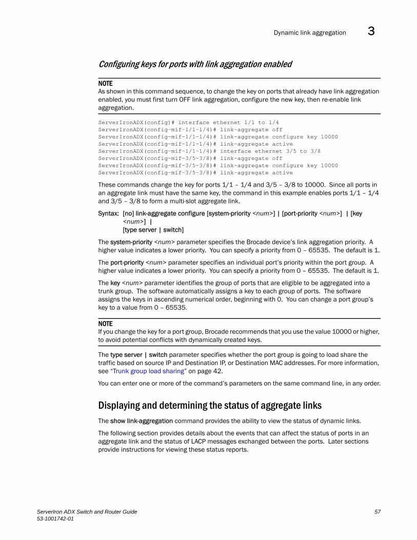
Dynamic link aggregation 3DRAFT: BROCADE CONFIDENTIAL
Configuring keys for ports with link aggregation enabled
NOTEAs shown in this command sequence, to change the key on ports that already have link aggregation enabled, you must first turn OFF link aggregation, configure the new key, then re-enable link aggregation.
ServerIronADX(config)# interface ethernet 1/1 to 1/4ServerIronADX(config-mif-1/1-1/4)# link-aggregate offServerIronADX(config-mif-1/1-1/4)# link-aggregate configure key 10000ServerIronADX(config-mif-1/1-1/4)# link-aggregate activeServerIronADX(config-mif-1/1-1/4)# interface ethernet 3/5 to 3/8ServerIronADX(config-mif-3/5-3/8)# link-aggregate offServerIronADX(config-mif-3/5-3/8)# link-aggregate configure key 10000ServerIronADX(config-mif-3/5-3/8)# link-aggregate active
These commands change the key for ports 1/1 – 1/4 and 3/5 – 3/8 to 10000. Since all ports in an aggregate link must have the same key, the command in this example enables ports 1/1 – 1/4 and 3/5 – 3/8 to form a multi-slot aggregate link.
Syntax: [no] link-aggregate configure [system-priority <num>] | [port-priority <num>] | [key <num>] |[type server | switch]
The system-priority <num> parameter specifies the Brocade device’s link aggregation priority. A higher value indicates a lower priority. You can specify a priority from 0 – 65535. The default is 1.
The port-priority <num> parameter specifies an individual port’s priority within the port group. A higher value indicates a lower priority. You can specify a priority from 0 – 65535. The default is 1.
The key <num> parameter identifies the group of ports that are eligible to be aggregated into a trunk group. The software automatically assigns a key to each group of ports. The software assigns the keys in ascending numerical order, beginning with 0. You can change a port group’s key to a value from 0 – 65535.
NOTEIf you change the key for a port group, Brocade recommends that you use the value 10000 or higher, to avoid potential conflicts with dynamically created keys.
The type server | switch parameter specifies whether the port group is going to load share the traffic based on source IP and Destination IP, or Destination MAC addresses. For more information, see “Trunk group load sharing” on page 42.
You can enter one or more of the command’s parameters on the same command line, in any order.
Displaying and determining the status of aggregate linksThe show link-aggregation command provides the ability to view the status of dynamic links.
The following section provides details about the events that can affect the status of ports in an aggregate link and the status of LACP messages exchanged between the ports. Later sections provide instructions for viewing these status reports.
ServerIron ADX Switch and Router Guide 5753-1001742-01
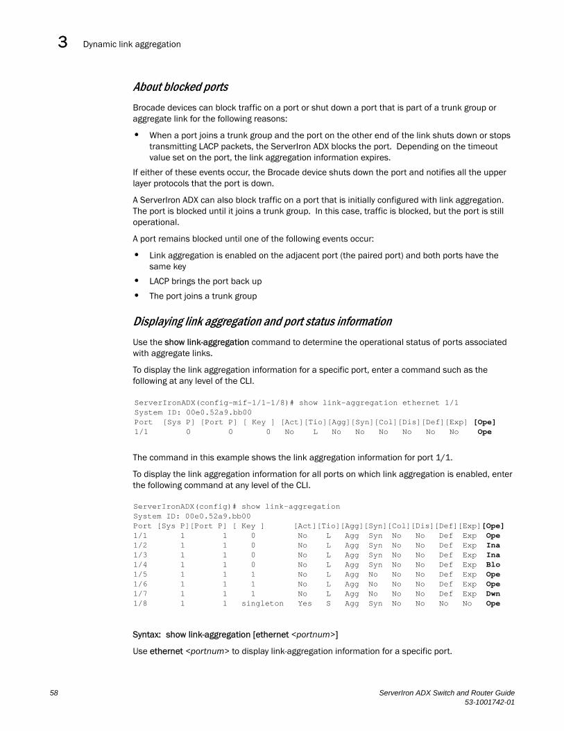
Dynamic link aggregation3DRAFT: BROCADE CONFIDENTIAL
About blocked ports
Brocade devices can block traffic on a port or shut down a port that is part of a trunk group or aggregate link for the following reasons:
• When a port joins a trunk group and the port on the other end of the link shuts down or stops transmitting LACP packets, the ServerIron ADX blocks the port. Depending on the timeout value set on the port, the link aggregation information expires.
If either of these events occur, the Brocade device shuts down the port and notifies all the upper layer protocols that the port is down.
A ServerIron ADX can also block traffic on a port that is initially configured with link aggregation. The port is blocked until it joins a trunk group. In this case, traffic is blocked, but the port is still operational.
A port remains blocked until one of the following events occur:
• Link aggregation is enabled on the adjacent port (the paired port) and both ports have the same key
• LACP brings the port back up
• The port joins a trunk group
Displaying link aggregation and port status information
Use the show link-aggregation command to determine the operational status of ports associated with aggregate links.
To display the link aggregation information for a specific port, enter a command such as the following at any level of the CLI.
The command in this example shows the link aggregation information for port 1/1.
To display the link aggregation information for all ports on which link aggregation is enabled, enter the following command at any level of the CLI.
Syntax: show link-aggregation [ethernet <portnum>]
Use ethernet <portnum> to display link-aggregation information for a specific port.
ServerIronADX(config-mif-1/1-1/8)# show link-aggregation ethernet 1/1System ID: 00e0.52a9.bb00Port [Sys P] [Port P] [ Key ] [Act][Tio][Agg][Syn][Col][Dis][Def][Exp] [Ope]1/1 0 0 0 No L No No No No No No Ope
ServerIronADX(config)# show link-aggregationSystem ID: 00e0.52a9.bb00Port [Sys P][Port P] [ Key ] [Act][Tio][Agg][Syn][Col][Dis][Def][Exp][Ope]1/1 1 1 0 No L Agg Syn No No Def Exp Ope1/2 1 1 0 No L Agg Syn No No Def Exp Ina1/3 1 1 0 No L Agg Syn No No Def Exp Ina1/4 1 1 0 No L Agg Syn No No Def Exp Blo1/5 1 1 1 No L Agg No No No Def Exp Ope1/6 1 1 1 No L Agg No No No Def Exp Ope1/7 1 1 1 No L Agg No No No Def Exp Dwn1/8 1 1 singleton Yes S Agg Syn No No No No Ope
58 ServerIron ADX Switch and Router Guide53-1001742-01

Dynamic link aggregation 3DRAFT: BROCADE CONFIDENTIAL
The show link aggregation command shows the following information.
TABLE 8 CLI display of link aggregation information
This field... Displays...
System ID Lists the base MAC address of the device. This is also the MAC address of port 1 (or 1/1).
Port Lists the port number.
Sys P Lists the system priority configured for this port.
Port P Lists the port’s link aggregation priority.
Key Lists the link aggregation key. singleton is displayed if the port is configured for single link LACP.
Act Indicates the link aggregation mode, which can be one of the following:• No – The mode is passive or link aggregation is disabled (off) on the port.
If link aggregation is enabled (and the mode is passive), the port can send and receive LACPDU messages to participate in negotiation of an aggregate link initiated by another port, but cannot search for a link aggregation port or initiate negotiation of an aggregate link.
• Yes – The mode is active. The port can send and receive LACPDU messages.
Tio Indicates the timeout value of the port. The timeout value can be one of the following: • L – Long. The trunk group has already been formed and the port is
therefore using a longer message timeout for the LACPDU messages exchanged with the remote port. Typically, these messages are used as confirmation of the health of the aggregate link.
• S – Short. The port has just started the LACPDU message exchange process with the port at the other end of the link. The S timeout value also can mean that the link aggregation information received from the remote port has expired and the ports are starting a new information exchange.
Agg Indicates the link aggregation state of the port. The state can be one of the following:• Agg – Link aggregation is enabled on the port.• No – Link aggregation is disabled on the port.
Syn Indicates the synchronization state of the port. The state can be one of the following:• No – The port is out of sync with the remote port. The port does not
understand the status of the LACPDU process and is not prepared to enter a trunk link.
• Syn – The port is in sync with the remote port. The port understands the status of the LACPDU message exchange process, and therefore knows the trunk group to which it belongs, the link aggregation state of the remote port, and so on.
Col Indicates the collection state of the port, which determines whether the port is ready to send traffic over the trunk link:• Col – The port is ready to send traffic over the trunk link.• No – The port is not ready to send traffic over the trunk link.
ServerIron ADX Switch and Router Guide 5953-1001742-01

Dynamic link aggregation3DRAFT: BROCADE CONFIDENTIAL
Displaying trunk group and LACP status information
Use the show trunk command to determine the status of LACP. Refer to “Displaying trunk group configuration information” on page 46.
Clearing the negotiated link aggregationsWhen a group of ports negotiates a trunk group configuration, the software stores the negotiated configuration in a table. You can clear the negotiated link aggregation configurations from the software. When you clear the information, the software does not remove link aggregation parameter settings you have configured. Only the configuration information negotiated using LACP is removed.
Dis Indicates the distribution state of the port, which determines whether the port is ready to receive traffic over the trunk link:• Dis – The port is ready to receive traffic over the trunk link.• No – The port is not ready to receive traffic over the trunk link.
Def Indicates whether the port is using default link aggregation values. The port uses default values if it has not received link aggregation information through LACP from the port at the remote end of the link. This field can have one of the following values:• Def – The port has not received link aggregation values from the port at
the other end of the link and is therefore using its default link aggregation LACP settings.
• No – The port has received link aggregation information from the port at the other end of the link and is using the settings negotiated with that port.
Exp Indicates whether the negotiated link aggregation settings have expired. The settings expire if the port does not receive an LACPDU message from the port at the other end of the link before the message timer expires. This field can have one of the following values:• Exp – The link aggregation settings this port negotiated with the port at
the other end of the link have expired. The port is now using its default link aggregation settings.
• No – The link aggregation values that this port negotiated with the port at the other end of the link have not expired, so the port is still using the negotiated settings.
Ope • Ope (operational) - The port is operating normally.• Ina (inactive) - The port is inactive because the port on the other side of
the link is down or has stopped transmitting LACP packets.• Blo (blocked) - The port is blocked because the adjacent port is not
configured with link aggregation or because it is not able to join a trunk group. To unblock the port and bring it to an operational state, enable link aggregation on the adjacent port and ensure that the ports have the same key.
TABLE 8 CLI display of link aggregation information (Continued)
This field... Displays...
60 ServerIron ADX Switch and Router Guide53-1001742-01

Single link LACP 3DRAFT: BROCADE CONFIDENTIAL
NOTEThe software automatically updates the link aggregation configuration based on LACPDU messages. However, clearing the link aggregation information can be useful if you are troubleshooting a configuration.
To clear the link aggregation information, enter the following command at the Privileged EXEC level of the CLI.
ServerIronADX# clear link-aggregate
Syntax: clear link-aggregate
Single link LACPA single instance of link aggregation (single link LACP) can be used to provide unidirectional link detection. Single link LACP is based on the 802.3ad LACP protocol, but allows you to form an aggregated link with only one Ethernet port. This is the preferred method for detecting unidirectional links across mult-vendor devices instead of link keep-alive (UDLD), since it is based on a standard rather than on a proprietary solution.
Configuring single link LACPTake into account the following when configuring single link LACP:
• single link LACP is supported on 1 GbE and 10 GbE ports
• single link LACP is not supported on static trunk ports
• single link LACP is not supported on ports that have the link-keepalive command (UDLD) configured.
• single link LACP is not intended for the creation of trunk groups.
To form a single link LACP, the ports on both sides of the link must have LACP enabled. You can then define a single link LACP at the interface level of the device as shown in the following.
ServerIronADX(config)# interface ethernet 1/1ServerIronADX(config-if-e1000-2/1)# link-aggregate configure singletonServerIronADX(config-if-e1000-2/1)#
Syntax: [no] link-aggregate configure singleton
If this command is configured on a port, the "key" column in the output for the show link-aggregation command displays "singleton" as described in “Displaying link aggregation and port status information” on page 58.
NOTEA key is automatically assigned to the singleton LACP port. The user is not allowed to assign a key to a port that is configured as a singleton.
ServerIron ADX Switch and Router Guide 6153-1001742-01

Single link LACP3DRAFT: BROCADE CONFIDENTIAL
62 ServerIron ADX Switch and Router Guide53-1001742-01

ServerIron ADX Switch and Router Guide53-1001742-01
DRAFT: BROCADE CONFIDENTIAL
Chapter
4
Configuring Virtual LANs (VLANs)In this chapter•Overview. . . . . . . . . . . . . . . . . . . . . . . . . . . . . . . . . . . . . . . . . . . . . . . . . . . . . . 63
•Routing between VLANs (Layer 3 Switches only) . . . . . . . . . . . . . . . . . . . . . 74
•Configuring IP subnet VLANs . . . . . . . . . . . . . . . . . . . . . . . . . . . . . . . . . . . . . 82
•Configuring the same IP subnet address on multiple port-based VLANs . . 84
•Configuring a virtual routing interface and assigning an IP address on a port-based VLAN 89
•Configuring VLAN groups and virtual routing interface groups . . . . . . . . . . 89
•Configuring super aggregated VLANs. . . . . . . . . . . . . . . . . . . . . . . . . . . . . . . 94
•Dual-mode VLAN ports . . . . . . . . . . . . . . . . . . . . . . . . . . . . . . . . . . . . . . . . . 101
•Displaying VLAN information. . . . . . . . . . . . . . . . . . . . . . . . . . . . . . . . . . . . . 104
This chapter describes how to configure Virtual LANs (VLANs) on a ServerIron ADX.
The “Overview” section provides basic information about VLAN options available on a ServerIron ADX. Following this section, other sections provide configuration procedures and examples.
To display configuration information for VLANs, refer to “Displaying VLAN information” on page 104.
OverviewThis section describes the ServerIron ADX VLAN features. Configuration procedures and examples appear in later sections of this chapter.
Types of VLANs supportedYou can configure the following types of VLANs on a ServerIron ADX.
• Layer 2 port-based VLAN– a set of physical ports that share a common, exclusive Layer 2 broadcast domain
• IP subnet VLANs – a subset of ports in a port-based VLAN that share a common, exclusive subnet broadcast domain for a specified IP subnet
When a ServerIron ADX device receives a packet on a port that is a member of a VLAN, the device forwards the packet based on the following VLAN hierarchy:
• If the port belongs to an IP subnet VLAN and the packet belongs to the corresponding IP subnet, the device forwards the packet to all the ports within that IP subnet VLAN.
63

Overview4DRAFT: BROCADE CONFIDENTIAL
• If the packet cannot be forwarded based on either of the VLAN membership types listed above, but the packet can be forwarded at Layer 2, the device forwards the packet on all the ports within the receiving port’s port-based VLAN.
Layer 2 port-based VLANs
You can configure port-based VLANs on a ServerIron ADX. A port-based VLAN is a subset of ports on a ServerIron ADX that constitutes a Layer 2 broadcast domain.
By default, all the ports on a ServerIron ADX are members of the default VLAN. Thus, all the ports on the ServerIron ADX constitute a single Layer 2 broadcast domain. You can configure multiple port-based VLANs. When you configure a port-based VLAN, the device automatically removes the ports you add to the VLAN from the default VLAN.
Figure 8 shows an example of a ServerIron ADX on which a Layer 2 port-based VLAN has been configured.
FIGURE 8 Brocade device containing user-defined Layer 2 port-based VLAN
When you add a port-based VLAN,the device removes all the ports in thenew VLAN from DEFAULT-VLAN.
User-configured port-based VLAN
DEFAULT-VLANVLAN ID = 1Layer 2 Port-based VLAN
64 ServerIron ADX Switch and Router Guide53-1001742-01
Overview 4DRAFT: BROCADE CONFIDENTIAL
A port can belong to only one port-based VLAN, unless you apply 802.1q tagging to the port. 802.1q tagging allows the port to add a four-byte tag field, which contains the VLAN ID, to each packet sent on the port. You also can configure port-based VLANs that span multiple devices by tagging the ports within the VLAN. The tag enables each device that receives the packet to determine the VLAN the packet belongs to. 802.1q tagging applies only to Layer 2 VLANs, not to Layer 3 VLANs.
Since each port-based VLAN is a separate Layer 2 broadcast domain, by default each VLAN runs a separate instance of the Spanning Tree Protocol (STP).
Layer 2 traffic is bridged within a port-based VLAN and Layer 2 broadcasts are sent to all the ports within the VLAN.
Integrated Switch Routing (ISR)
The Integrated Switch Routing (ISR) feature enables VLANs configured on ServerIron ADX Layer 3 Switches to route Layer 3 traffic from one IP subnet to another. Normally, to route traffic from one IP subnet VLAN to another, you would need to forward the traffic to an external router. The VLANs provide Layer 3 broadcast domains for these protocols but do not in themselves provide routing services for these protocols. This is true even if the source and destination IP subnets, are on the same device.
ISR eliminates the need for an external router by allowing you to route between VLANs using virtual routing interfaces (ves). A virtual routing interface is a logical port on which you can configure Layer 3 routing parameters. You configure a separate virtual routing interface on each VLAN that you want to be able to route from or to. For example, if you configure two IP subnet VLANs on a Layer 3 Switch, you can configure a virtual routing interface on each VLAN, then configure IP routing parameters for the subnets. Thus, the Layer 3 Switch forwards IP subnet broadcasts within each VLAN at Layer 2 but routes Layer 3 traffic between the VLANs using the virtual routing interfaces.
NOTEThe Layer 3 Switch uses the lowest MAC address on the device (the MAC address of port 1 or 1/1) as the MAC address for all ports within all virtual routing interfaces you configure on the device.
The routing parameters and the syntax for configuring them are the same as when you configure a physical interface for routing.
All the ports within an IP Subnet VLAN must be in the same port-based VLAN. The IP Subnet VLAN cannot have ports in multiple port-based VLANs, unless the ports in the port-based VLAN to which you add the IP Subnet VLAN are 802.1q tagged.
You can configure multiple IP Subnet VLANs within the same port-based VLAN. In addition, a port within a port-based VLAN can belong to multiple VLANs. For example, if you have a port-based VLAN that contains ports 1 – 10, you can configure port 5 as a member of more than one IP Subnet.
IP subnet VLANs
For IP, you can provide more granular broadcast control by instead creating the following types of VLAN:
• IP subnet VLAN – An IP subnet broadcast domain for a specific IP subnet.
ServerIron ADX Switch and Router Guide 6553-1001742-01

Overview4DRAFT: BROCADE CONFIDENTIAL
The ServerIron ADX routes packets between VLANs at Layer 3. To configure an IP subnet VLAN to route, you must add a virtual routing interface to the VLAN, then configure the appropriate routing parameters on the virtual routing interface.
NOTEThe Layer 3 Switch routes packets between VLANs of the same protocol. The Layer 3 Switch cannot route from one protocol to another.
Default VLANBy default, all the ports on a ServerIron ADX are in a single port-based VLAN. This VLAN is called DEFAULT-VLAN and is VLAN number 1.
Figure 9 shows an example of the default Layer 2 port-based VLAN.
FIGURE 9 Default Layer 2 port-based VLAN
When you configure a port-based VLAN, one of the configuration items you provide is the ports that are in the VLAN. When you configure the VLAN, the ServerIron ADX automatically removes the ports that you place in the VLAN from DEFAULT-VLAN. By removing the ports from the default VLAN, the ServerIron ADX ensures that each port resides in only one Layer 2 broadcast domain.
NOTEInformation for the default VLAN is available only after you define another VLAN.
DEFAULT-VLANVLAN ID = 1Layer 2 Port-based VLAN
By default, all ports belong to a singleport-based VLAN, DEFAULT-VLAN.Thus, all ports belong to a singleLayer 2 broadcast domain.
66 ServerIron ADX Switch and Router Guide53-1001742-01

Overview 4DRAFT: BROCADE CONFIDENTIAL
Some network configurations may require that a port be able to reside in two or more Layer 2 broadcast domains (port-based VLANs). In this case, you can enable a port to reside in multiple port-based VLANs by tagging the port. See the following section.
If your network requires that you use VLAN ID 1 for a user-configured VLAN, you can reassign the default VLAN to another valid VLAN ID. Refer to “Assigning a different VLAN ID to the default VLAN” on page 75.
802.1q tagging802.1q tagging is an IEEE standard that allows a networking device to add information to a Layer 2 packet in order to identify the VLAN membership of the packet. A ServerIron ADX tags a packet by adding a four-byte tag to the packet. The tag contains the tag value, which identifies the data as a tag, and also contains the VLAN ID of the VLAN from which the packet is sent.
The tag contains the following:
• The default tag value is 8100 (hexadecimal). This value comes from the 802.1q specification. You can change this tag value on a global basis on a ServerIron ADX if needed to be compatible with other vendors’ equipment.
• The VLAN ID is determined by the VLAN on which the packet is being forwarded.
Figure 10 shows the format of packets with and without the 802.1q tag. The tag format is vendor-specific. To use the tag for VLANs configured across multiple devices, make sure all the devices support the same tag format.
FIGURE 10 Packet containing an 802.1QVLAN tag
Untagged Packet Format
6 bytes
DestinationAddress
6 bytes
SourceAddress
2 bytes
TypeField
Up to 1500 bytes
Data Field4 bytes
CRC Ethernet II
IEEE 802.3
802.1q Tagged Packet Format
4 bytes
802.1qTag
Ethernet II with 802.1q tag
IEEE 802.3 with 802.1q tag
Tag Protocol Id (TPID)Octet 1 Octet 2
802.1p(3 bits)
VLAN ID (12 bits)
Octet 41 2 3 4 5 6 7 8
6 bytes
DestinationAddress
6 bytes
SourceAddress
2 bytes
LengthField
Up to 1496 bytes
Data Field4 bytes
CRC
6 bytes
DestinationAddress
6 bytes
DestinationAddress
6 bytes
SourceAddress
6 bytes
SourceAddress
4 bytes
802.1qTag
2 bytes
TypeField
2 bytes
LengthField
Up to 1500 bytes
Data Field
Up to 1496 bytes
Data Field
4 bytes
CRC
4 bytes
CRC
ServerIron ADX Switch and Router Guide 6753-1001742-01

Overview4DRAFT: BROCADE CONFIDENTIAL
NOTEYou cannot configure a port to be a member of the default port-based VLAN and another port-based VLAN at the same time. Once you add a port to a port-based VLAN, the port is no longer a member of the default VLAN. The port returns to the default VLAN only if you delete the other VLANs that contains the port.
If you configure a VLAN that spans multiple devices, you need to use tagging only if a port connecting one of the devices to the other is a member of more than one port-based VLAN. If a port connecting one device to the other is a member of only a single port-based VLAN, tagging is not required.
If you use tagging on multiple devices, each device must be configured for tagging and must use the same tag value. In addition, the implementation of tagging must be compatible on the devices. The tagging on all Brocade devices is compatible with other Brocade devices.
Figure 11 shows an example of two devices that have the same Layer 2 port-based VLANs configured across them. Notice that only one of the VLANs requires tagging.
FIGURE 11 VLANs configured across multiple devices
Spanning Tree Protocol (STP)The default state of STP depends on the device type:
• STP is disabled by default on Brocade Layer 3 Switches.
• STP is enabled by default on Brocade Layer 2 Switches.
Also by default, each port-based VLAN has a separate instance of STP. Thus, when STP is globally enabled, each port-based VLAN on the device runs a separate spanning tree.
You can enable or disable STP on the following levels:
• Globally – Affects all ports on the device.
User-configured port-based VLAN
T = 802.1Q tagged port
T T
T T
T
T
Segment 1
Segment 2
T
Segment 2Segment 1
Tagging is required for the portson Segment 1 because the portsare in multiple port-based VLANs.
Without tagging, a device receivingVLAN traffic from the other devicewould not be sure which VLAN thetraffic is for.
Tagging is not required for the portson Segment 2 because each port isin only one port-based VLAN.
68 ServerIron ADX Switch and Router Guide53-1001742-01

Overview 4DRAFT: BROCADE CONFIDENTIAL
NOTEIf you configure a port-based VLAN on the device, the VLAN has the same STP state as the default STP state on the device. Thus, on Layer 2 Switches, new VLANs have STP enabled by default. On Layer 3 Switches, new VLANs have STP disabled by default. You can enable or disable STP in each VLAN separately. In addition, you can enable or disable STP on individual ports.
• Port-based VLAN – Affects all ports within the specified port-based VLAN.
STP is a Layer 2 protocol. Thus, you cannot enable or disable STP for individual protocol VLANs or for IP subnet VLANs. The STP state of a port-based VLAN containing these other types of VLANs determines the STP state for all the Layer 2 broadcasts within the port-based VLAN. This is true even though Layer 3 protocol broadcasts are sent on Layer 2 within the VLAN.
It is possible that STP will block one or more ports in a IP subnet VLAN that uses a virtual routing interface to route to other VLANs. For IP subnet VLANs, even though some of the physical ports of the virtual routing interface are blocked, the virtual routing interface can still route so long as at least one port in the virtual routing interface’s protocol VLAN is not blocked by STP.
If you enable Single STP (SSTP) on the device, the ports in all VLANs on which STP is enabled become members of a single spanning tree. The ports in VLANs on which STP is disabled are excluded from the single spanning tree.
For more information, refer to Chapter 5, “Configuring Spanning Tree Protocol (STP) and IronSpanAdvanced STP Features”.
Virtual routing interfacesA virtual routing interface is a logical routing interface that Brocade Layer 3 Switches use to route Layer 3 protocol traffic between protocol VLANs.
Brocade devices send Layer 3 traffic at Layer 2 within a VLAN. However, Layer 3 traffic from one VLAN to another must be routed.
If you want the device to be able to send Layer 3 traffic from one VLAN to another, you must configure a virtual routing interface on each VLAN, then configure routing parameters on the virtual routing interfaces. For example, to enable a Layer 3 Switch to route IP traffic from one VLAN to another, you must configure a virtual routing interface on each VLAN, then configure the appropriate IP routing parameters on each of the virtual routing interfaces.
Figure 12 shows an example of IP subnet VLANs that use virtual routing interfaces for routing.
ServerIron ADX Switch and Router Guide 6953-1001742-01
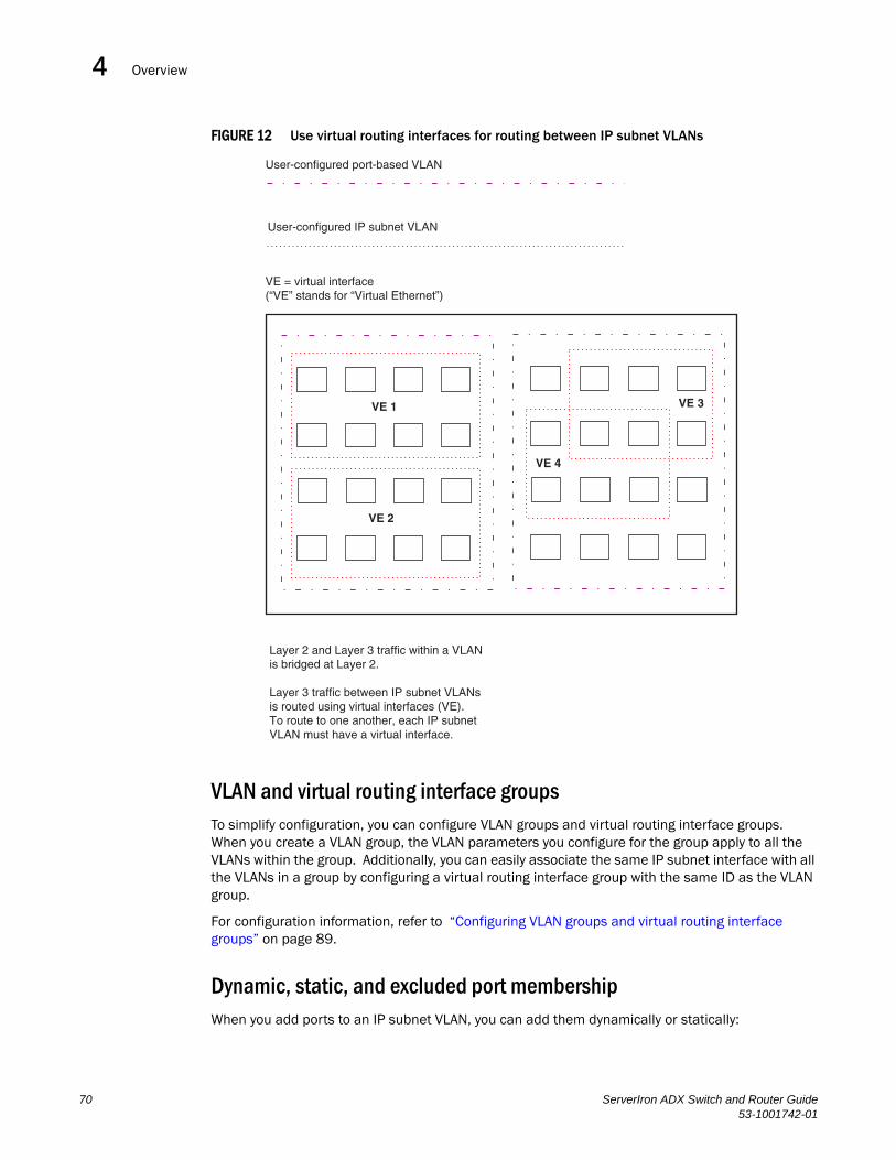
Overview4DRAFT: BROCADE CONFIDENTIAL
FIGURE 12 Use virtual routing interfaces for routing between IP subnet VLANs
VLAN and virtual routing interface groupsTo simplify configuration, you can configure VLAN groups and virtual routing interface groups. When you create a VLAN group, the VLAN parameters you configure for the group apply to all the VLANs within the group. Additionally, you can easily associate the same IP subnet interface with all the VLANs in a group by configuring a virtual routing interface group with the same ID as the VLAN group.
For configuration information, refer to “Configuring VLAN groups and virtual routing interface groups” on page 89.
Dynamic, static, and excluded port membershipWhen you add ports to an IP subnet VLAN, you can add them dynamically or statically:
User-configured port-based VLAN
User-configured IP subnet VLAN
VE = virtual interface(“VE” stands for “Virtual Ethernet”)
VE 1
VE 2
VE 3
VE 4
Layer 2 and Layer 3 traffic within a VLANis bridged at Layer 2.
Layer 3 traffic between IP subnet VLANsis routed using virtual interfaces (VE).To route to one another, each IP subnetVLAN must have a virtual interface.
70 ServerIron ADX Switch and Router Guide53-1001742-01

Overview 4DRAFT: BROCADE CONFIDENTIAL
• Dynamic ports
• Static ports
You also can explicitly exclude ports.
Dynamic ports
Dynamic ports are added to a VLAN when you create the VLAN. However, if a dynamically added port does not receive any traffic for the VLAN’s IP subnet within ten minutes, the port is removed from the VLAN. However, the port remains a candidate for port membership. Thus, if the port receives traffic for the VLAN’s IP subnet, the ServerIron ADX adds the port back to the VLAN.
After the port is added back to the VLAN, the port can remain an active member of the VLAN up to 20 minutes without receiving traffic for the VLAN’s protocol. If the port ages out, it remains a candidate for VLAN membership and is added back to the VLAN when the VLAN receives protocol traffic. At this point, the port can remain in the VLAN up to 20 minutes without receiving traffic for the VLAN’s IP subnet, and so on.
Unless you explicitly add a port statically or exclude a port, the port is a dynamic port and thus can be an active member of the VLAN, depending on the traffic it receives.
Figure 13 shows an example of a VLAN with dynamic ports. Dynamic ports not only join and leave the VLAN according to traffic, but also allow some broadcast packets of the specific protocol to “leak” through the VLAN. Refer to “Broadcast leaks” on page 72.
FIGURE 13 VLAN with dynamic ports—all ports are active when you create the VLAN
Ports in a new IP subnet VLAN that do not receive traffic for the VLAN’s protocol age out after 20 minutes and become candidate ports. Figure 14 shows what happens if a candidate port receives traffic for the VLAN’s protocol.
A = active port
C = candidate port
When you add ports dynamically,all the ports are added when you addthe VLAN.
A A A A
A A A A
ServerIron ADX Switch and Router Guide 7153-1001742-01

Overview4DRAFT: BROCADE CONFIDENTIAL
FIGURE 14 VLAN with dynamic ports—candidate ports become active again if they receive protocol traffic
Static ports
Static ports are permanent members of the IP subnet VLAN. The ports remain active members of the VLAN regardless of whether the ports receive traffic for the VLAN’s protocol. You must explicitly identify the port as a static port when you add it to the VLAN. Otherwise, the port is dynamic and is subject to aging out.
Excluded ports
If you want to prevent a port in a port-based VLAN from ever becoming a member of an IP subnet VLAN configured in the port-based VLAN, you can explicitly exclude the port. You exclude the port when you configure the IP subnet VLAN.
Excluded ports do not leak broadcast packets. Refer to “Broadcast leaks” on page 72.
Broadcast leaks
A dynamic port becomes a member of a Layer 3 protocol VLAN when traffic from the VLAN's protocol is received on the port. After this point, the port remains an active member of the protocol VLAN, unless the port does not receive traffic from the VLAN's protocol for 20 minutes. If the port does not receive traffic for the VLAN's protocol for 20 minutes, the port ages out and is no longer an active member of the VLAN.
Ports that time out remain candidates membership in the VLAN and become activeagain if they receive traffic for the VLANsIP subnet range.
When a candidate port rejoins a VLAN,the timeout for that port becomes 20 minutes.Thus, the port remains an active member ofthe VLAN even if it does not receive trafficfor 20 minutes. After that, the port becomesa candidate port again.
C C
A A A A
A A
72 ServerIron ADX Switch and Router Guide53-1001742-01

Overview 4DRAFT: BROCADE CONFIDENTIAL
To enable a host that has been silent for awhile to send and receive packets, the dynamic ports that are currently members of the Layer 3 protocol VLAN "leak" Layer 3 broadcast packets to the ports that have aged out. When a host connected to one of the aged out ports responds to a leaked broadcast, the port is added to the protocol VLAN again.
To "leak" Layer 3 broadcast traffic, an active port sends 1/8th of the Layer 3 broadcast traffic to the inactive (aged out) ports.
Static ports do not age out and do not leak broadcast packets.
Super aggregated VLANsYou can aggregate multiple VLANs within another VLAN. This feature allows you to construct Layer 2 paths and channels. This feature is particularly useful for Virtual Private Network (VPN) applications in which you need to provide a private, dedicated Ethernet connection for an individual client to transparently reach its subnet across multiple networks.
For an application example and configuration information, refer to “Configuring super aggregated VLANs” on page 94.
Trunk group ports and VLAN membershipA trunk group is a set of physical ports that are configured to act as a single physical interface. Each trunk group’s port configuration is based on the configuration of the lead port, which is the lowest numbered port in the group.
If you add a trunk group’s lead port to a VLAN, all of the ports in the trunk group become members of that VLAN.
Summary of VLAN configuration rulesA hierarchy of VLANs exists between the Layer 2 and Layer 3 protocol-based VLANs:
• Port-based VLANs are at the lowest level of the hierarchy.
• IP subnet VLANs are at the top of the hierarchy.
As a ServerIron ADX receives packets, the VLAN classification starts from the highest level VLAN first. Therefore, if an interface is configured as a member of both a port-based VLAN and an IP subnet VLAN, IP packets coming into the interface are classified as members of the IP subnet VLAN because that VLAN is higher in the VLAN hierarchy.
Multiple VLAN membership rules
The rules for multiple VLAN membership are as follows:
• A port can belong to multiple, unique, overlapping IP subnet VLANs without VLAN tagging.
• A port can belong to multiple, overlapping Layer 2 port-based VLANs only if the port is a tagged port. Packets sent out of a tagged port use an 802.1q-tagged frame.
• When both port and IP subnet VLANs are configured on a given device, all IP subnet VLANs must be strictly contained within a port-based VLAN. An IP subnet VLAN cannot include ports from multiple port-based VLANs. This rule is required to ensure that port-based VLANs remain loop-free Layer 2 broadcast domains.
• Multiple IP subnet VLANs are configurable within each port-based VLAN on the Layer 2 Switch.
ServerIron ADX Switch and Router Guide 7353-1001742-01

Routing between VLANs (Layer 3 Switches only)4DRAFT: BROCADE CONFIDENTIAL
• Removing a configured port-based VLAN from a Layer-2 or Layer 3 Switch automatically removes any protocol-based VLAN, IP subnet VLAN, AppleTalk cable VLAN, or IPX network VLAN, or any Virtual Ethernet router interfaces defined within the Port-based VLAN.
Routing between VLANs (Layer 3 Switches only)Brocade Layer 3 Switches can locally route IP between VLANs defined within a single router. All other routable protocols or protocol VLANs (for example, DecNet) must be routed by another external router capable of routing the protocol.
Virtual routing interfaces (Layer 3 Switches only)You need to configure virtual routing interfaces if an IP subnet VLAN needs to route IP packets to another port-based VLAN on the same router. A virtual routing interface can be associated with the ports in only a single port-based VLAN. Virtual router interfaces must be defined at the highest level of the VLAN hierarchy.
If you do not need to further partition the port-based VLAN by defining separate Layer 3 VLANs, you can define a single virtual routing interface at the port-based VLAN level and enable IP routing on a single virtual routing interface.
Bridging and routing the same protocol simultaneously on the same device (Layer 3 Switches only)Some configurations may require simultaneous switching and routing of the same single protocol across different sets of ports on the same router. When IP routing is enabled on a Brocade Layer 3 Switch, you can route these protocols on specific interfaces while bridging them on other interfaces. In this scenario, you can create two separate backbones for the same protocol, one bridged and one routed.
To bridge IP at the same time these protocols are being routed, you need to configure an IP subnet VLAN and not assign a virtual routing interface to the VLAN. Packets for these protocols are bridged or switched at Layer 2 across ports on the router that are included in the Layer 3 VLAN. If these VLANs are built within port-based VLANs, they can be tagged across a single set of backbone fibers to create separate Layer 2 switched and Layer 3 routed backbones for the same protocol on a single physical backbone.
Routing between VLANs using virtual routing interfaces (Layer 3 Switches only)Brocade calls the ability to route between VLANs with virtual routing interfaces Integrated Switch Routing (ISR). There are some important concepts to understand before designing an ISR backbone.
Virtual router interfaces can be defined on port-based, IP subnet VLANs.
To create any type of VLAN on a Brocade Layer 3 Switch, Layer 2 forwarding must be enabled. When Layer 2 forwarding is enabled, the Layer 3 Switch becomes a Switch on all ports for all non-routable protocols.
74 ServerIron ADX Switch and Router Guide53-1001742-01

Routing between VLANs (Layer 3 Switches only) 4DRAFT: BROCADE CONFIDENTIAL
If the router interfaces for IP are configured on physical ports, then routing occurs independent of the Spanning Tree Protocol (STP). However, if the router interfaces are defined for any type VLAN, they are virtual routing interfaces and are subject to the rules of STP.
If your backbone is consisted of virtual routing interfaces all within the same STP domain, it is a bridged backbone, not a routed one. This means that the set of backbone interfaces that are blocked by STP will be blocked for routed protocols as well. The routed protocols will be able to cross these paths only when the STP state of the link is FORWARDING. This problem is easily avoided by proper network design.
When designing an ISR network, pay attention to your use of virtual routing interfaces and the spanning-tree domain. If Layer 2 switching of your routed protocols (IP) is not required across the backbone, then the use of virtual routing interfaces can be limited to edge switch ports within each router. Full backbone routing can be achieved by configuring routing on each physical interface that connects to the backbone. Routing is independent of STP when configured on a physical interface.
If your ISR design requires that you switch IP at Layer 2 while simultaneously routing the same protocol over a single backbone, then create multiple port-based VLANs and use VLAN tagging on the backbone links to separate your Layer 2 switched and Layer 3 routed networks.
There is a separate STP domain for each port-based VLAN. Routing occurs independently across port-based VLANs or STP domains. You can define each end of each backbone link as a separate tagged port-based VLAN. Routing will occur independently across the port-based VLANs. Because each port-based VLAN’s STP domain is a single point-to-point backbone connection, you are guaranteed to never have an STP loop. STP will never block the virtual router interfaces within the tagged port-based VLAN, and you will have a fully routed backbone.
Dynamic port assignment (Layer 2 Switches and Layer 3 Switches)All switch ports are dynamically assigned to any Layer 3 VLAN on Brocade Layer 2 Switches and any non-routable VLAN on Brocade Layer 3 Switches. To maintain explicit control of the VLAN, you can explicitly exclude ports when configuring any Layer 3 VLAN on a Brocade Layer 2 Switch or any non-routable Layer 3 VLAN on a Brocade Layer 3 Switch.
If you do not want the ports to have dynamic membership, you can add them statically. This eliminates the need to explicitly exclude the ports that you do not want to participate in a particular Layer 3 VLAN.
Assigning a different VLAN ID to the default VLANWhen you enable port-based VLANs, all ports in the system are added to the default VLAN. By default, the default VLAN ID is “VLAN 1”. The default VLAN is not configurable. If you want to use the VLAN ID “VLAN 1” as a configurable VLAN, you can assign a different VLAN ID to the default VLAN.
To reassign the default VLAN to a different VLAN ID, enter the following command.
ServerIron(config)# default-vlan-id 4095
Syntax: [no] default-vlan-d <vlan-id>
You must specify a valid VLAN ID that is not already in use. For example, if you have already defined VLAN 10, do not try to use “10” as the new VLAN ID for the default VLAN. Valid VLAN IDs are numbers from 1 – 4096.
ServerIron ADX Switch and Router Guide 7553-1001742-01
Routing between VLANs (Layer 3 Switches only)4DRAFT: BROCADE CONFIDENTIAL
NOTEChanging the default VLAN name does not change the properties of the default VLAN. Changing the name allows you to use the VLAN ID “1” as a configurable VLAN.
NOTEVLAN ID 4094 is reserved for use by Single STP.
Assigning trunk group portsWhen a “lead” trunk group port is assigned to a VLAN, all other members of the trunk group are automatically added to that VLAN. A lead port is the first port of a trunk group port range; for example, “1” in 1 – 4 or “5” in 5 – 8. Refer to “Trunk group rules” on page 41 for more information.
Configuring port-based VLANsPort-based VLANs allow you to provide separate spanning tree protocol (STP) domains or broadcast domains on a port-by-port basis.
This section describes how to perform the following tasks for port-based VLANs using the CLI:
• Create a VLAN.
• Delete a VLAN.
• Modify a VLAN.
• Assign a higher priority to the VLAN.
• Change a VLAN’s priority.
• Enable or disable STP on the VLAN.
Example
Figure 15 shows a simple port-based VLAN configuration using a single Brocade Layer 2 Switch. All ports within each VLAN are untagged. One untagged port within each VLAN is used to connect the Layer 2 Switch to a Layer 3 Switch (in this example, a NetIron) for Layer 3 connectivity between the two port-based VLANs.
76 ServerIron ADX Switch and Router Guide53-1001742-01

Routing between VLANs (Layer 3 Switches only) 4DRAFT: BROCADE CONFIDENTIAL
FIGURE 15 Port-based VLANs 222 and 333
To create the two port-based VLANs shown in Figure 15, use the following method.
ServerIron(config)# vlan 222 by portServerIron(config-vlan-222)# untag e 1 to 8ServerIron(config-vlan-222)# vlan 333 by portServerIron(config-vlan-333)# untag e 9 to 16
Syntax: vlan <vlan-id> by port
Syntax: untagged ethernet <portnum> [to <portnum> | ethernet <portnum>]
Example
Figure 16 shows a more complex port-based VLAN configuration using multiple Layer 2 Switches and IEEE 802.1q VLAN tagging. The backbone link connecting the three Layer 2 Switches is tagged. One untagged port within each port-based VLAN on ServerIron-A connects each separate network wide Layer 2 broadcast domain to the router for Layer 3 forwarding between broadcast domains. The STP priority is configured to force ServerIron-A to be the root bridge for VLANs RED and BLUE. The STP priority on ServerIron-B is configured so that ServerIron-B is the root bridge for VLANs GREEN and BROWN.
ServerIron ADX
ServerIronADX
interface e 1IP Subnet 1
VLAN 222Ports 1 - 8
VLAN 333Ports 9 - 16
Ports 2 - 8IP Subnet 1
Ports 9 - 16IP Subnet 2
interface e 2IP Subnet 2
Port 1 Port 9
ServerIron ADX Switch and Router Guide 7753-1001742-01

Routing between VLANs (Layer 3 Switches only)4DRAFT: BROCADE CONFIDENTIAL
FIGURE 16 More complex port-based VLAN
To configure the Port-based VLANs on the ServerIron ADX Layer 2 Switches in Figure 16, use the following method.
Configuring ServerIron ADX-A
Enter the following commands to configure ServerIron ADX-A.
ServerIron> enableServerIron# configure terminalServerIron(config)# hostname ServerIron-AServerIron-A(config)# vlan 2 name BROWNServerIron-A(config-vlan-2)# untag ethernet 1 to 4 ethernet 17ServerIron-A(config-vlan-2)# tag ethernet 25 to 26ServerIron-A(config-vlan-2)# spanning-treeServerIron-A(config-vlan-2)# vlan 3 name GREENServerIron-A(config-vlan-3)# untag ethernet 5 to 8 ethernet 18 ServerIron-A(config-vlan-3)# tag ethernet 25 to 26ServerIron-A(config-vlan-3)# spanning-treeServerIron-A(config-vlan-3)# vlan 4 name BLUEServerIron-A(config-vlan-4)# untag ethernet 9 to 12 ethernet 19 ServerIron-A(config-vlan-4)# tag ethernet 25 to 26ServerIron-A(config-vlan-4)# spanning-treeServerIron-A(config-vlan-4)# spanning-tree priority 500ServerIron-A(config-vlan-4)# vlan 5 name REDServerIron-A(config-vlan-5)# untag ethernet 13 to 16 ethernet 20ServerIron-A(config-vlan-5)# tag ethernet 25 to 26ServerIron-A(config-vlan-5)# spanning-treeServerIron-A(config-vlan-5)# spanning-tree priority 500ServerIron-A(config-vlan-5)# endServerIron-A# write memory
Router
IP Subnet1 IP Subnet2 IP Subnet3 IP Subnet4
Port 17 Port 18 Port 19 Port 20
= STP Bloced VLAN ServerIron-A
ServerIron-B
Se
VLAN 2Port 1-4IP Sub1
VLAN 3Port 5-8IP Sub2
VLAN 4Port 9-12IP Sub3
VLAN 5Port 13-16IP Sub4
ROOT BRIDGEFOR
VLAN - BLUEVLAN - RED
ROOT BRIDGEFOR
VLAN - BROWNVLAN - GREEN
VLAN 2P 1 4
VLAN 3P t 5 8
VLAN 4P t 9 12
VLAN 5P t 13 16
VLAN 2P t 1 4
VLAN 3Port 5 8
VLAN 4P t 9 12
VLP
Router
IP Subnet1 IP Subnet2 IP Subnet3 IP Subnet4
Port 17 Port 18 Port 19 Port 20
= STP Bloced VLAN ServerIron-A
ServerIron-B
ServerIron-C
VLAN 2Port 1-4IP Sub1
VLAN 3Port 5-8IP Sub2
VLAN 4Port 9-12IP Sub3
VLAN 5Port 13-16IP Sub4
ROOT BRIDGEFOR
VLAN - BLUEVLAN - RED
ROOT BRIDGEFOR
VLAN - BROWNVLAN - GREEN
VLAN 2Port 1-4IP Sub1
VLAN 3Port 5-8IP Sub2
VLAN 4Port 9-12IP Sub3
VLAN 5Port 13-16IP Sub4
VLAN 2Port 1-4IP Sub1
VLAN 3Port 5-8IP Sub2
VLAN 4Port 9-12IP Sub3
VLAN 5Port 13-16IP Sub4
78 ServerIron ADX Switch and Router Guide53-1001742-01

Routing between VLANs (Layer 3 Switches only) 4DRAFT: BROCADE CONFIDENTIAL
Configuring ServerIron ADX-B
Enter the following commands to configure ServerIron-B.
ServerIron> enableServerIron# configure terminalServerIron(config)# hostname ServerIron-BServerIron-B(config)# vlan 2 name BROWNServerIron-B(config-vlan-2)# untag ethernet 1 to 4ServerIron-B(config-vlan-2)# tag ethernet 25 to 26ServerIron-B(config-vlan-2)# spanning-treeServerIron-B(config-vlan-2)# spanning-tree priority 500ServerIron-B(config-vlan-2)# vlan 3 name GREENServerIron-B(config-vlan-3)# untag ethernet 5 to 8ServerIron-B(config-vlan-3)# tag ethernet 25 to 26ServerIron-B(config-vlan-3)# spanning-treeServerIron-B(config-vlan-3)# spanning-tree priority 500ServerIron-B(config-vlan-3)# vlan 4 name BLUEServerIron-B(config-vlan-4)# untag ethernet 9 to 12ServerIron-B(config-vlan-4)# tag ethernet 25 to 26ServerIron-B(config-vlan-4)# vlan 5 name REDServerIron-B(config-vlan-5)# untag ethernet 13 to 16ServerIron-B(config-vlan-5)# tag ethernet 25 to 26ServerIron-B(config-vlan-5)# endServerIron-B# write memory
Configuring ServerIron ADX-C
Enter the following commands to configure ServerIron-C.
ServerIron> enServerIron# configure terminalServerIron(config)# hostname ServerIron-CServerIron-C(config)# vlan 2 name BROWNServerIron-C(config-vlan-2)# untag ethernet 1 to 4ServerIron-C(config-vlan-2)# tag ethernet 25 to 26ServerIron-C(config-vlan-2)# vlan 3 name GREENServerIron-C(config-vlan-3)# untag ethernet 5 to 8ServerIron-C(config-vlan-3)# tag ethernet 25 to 26ServerIron-C(config-vlan-3)# vlan 4 name BLUEServerIron-C(config-vlan-4)# untag ethernet 9 to 12ServerIron-C(config-vlan-4)# tag ethernet 25 to 26ServerIron-C(config-vlan-4)# vlan 5 name REDServerIron-C(config-vlan-5)# untag ethernet 13 to 16ServerIron-C(config-vlan-5)# tag ethernet 25 to 26ServerIron-C(config-vlan-5)# endServerIron-C# write memory
Syntax: vlan <vlan-id> by port
Syntax: untagged ethernet | pos <portnum> [to <portnum> | ethernet <portnum>]
Syntax: tagged ethernet | pos <portnum> [to <portnum> | ethernet <portnum>]
Syntax: [no] spanning-tree
Syntax: spanning-tree [ethernet <portnum> path-cost <value> priority <value>] forward-delay <value> hello-time <value> maximum-age <time> priority <value>
ServerIron ADX Switch and Router Guide 7953-1001742-01

Routing between VLANs (Layer 3 Switches only)4DRAFT: BROCADE CONFIDENTIAL
Modifying a port-based VLANYou can make the following modifications to a port-based VLAN:
• Add or delete a VLAN port.
• Change its priority.
• Enable or disable STP.
Removing a port-based VLAN
Suppose you want to remove VLAN 5 from the example in Figure 16. To do so, use the following procedure.
1. Access the global CONFIG level of the CLI on by entering the following commands.
ServerIron-A> enableNo password has been assigned yet...ServerIron-A# configure terminalServerIron-A(config)#
2. Enter the following command.
ServerIron-A(config)# no vlan 5ServerIron-A(config)#
3. Enter the following commands to exit the CONFIG level and save the configuration to the system-config file on flash memory.
ServerIron-A(config)#ServerIron-A(config)# endServerIron-A# write memoryServerIron-A#
4. Repeat steps 1 – 3 on ServerIron-B.
Syntax: no vlan <vlan-id> by port
Removing a port from a VLAN
Suppose you want to remove port 11 from VLAN 4 on ServerIron-A shown in Figure 16. To do so, use the following procedure.
1. Access the global CONFIG level of the CLI on ServerIron-A by entering the following command.
ServerIron-A> enableNo password has been assigned yet...ServerIron-A# configure terminalServerIron-A(config)#
2. Access the level of the CLI for configuring port-based VLAN 4 by entering the following command.
ServerIron-A(config)#ServerIron-A(config)# vlan 4ServerIron-A(config-vlan-4)#
3. Enter the following commands.
80 ServerIron ADX Switch and Router Guide53-1001742-01

Routing between VLANs (Layer 3 Switches only) 4DRAFT: BROCADE CONFIDENTIAL
ServerIron-A(config-vlan-4)#ServerIron-A(config-vlan-4)# no untag ethernet 11deleted port ethe 11 from port-vlan 4.ServerIron-A(config-vlan-4)#
4. Enter the following commands to exit the VLAN CONFIG mode and save the configuration to the system-config file on flash memory.
ServerIron-A(config-vlan-4)#ServerIron-A(config-vlan-4)# endServerIron-A# write memoryServerIron-A#
Enable spanning tree on a VLAN
The spanning tree bridge and port parameters are configurable using one CLI command set at the Global Configuration Level of each Port-based VLAN. Suppose you want to enable the IEEE 802.1d STP across VLAN 3. To do so, use the following method.
NOTEWhen port-based VLANs are not operating on the system, STP is set on a system-wide level at the global CONFIG level of the CLI.
1. Access the global CONFIG level of the CLI on ServerIron-A by entering the following commands.
ServerIron-A> enableNo password has been assigned yet...ServerIron-A# configure terminalServerIron-A(config)#
2. Access the level of the CLI for configuring port-based VLAN 3 by entering the following command.
ServerIron-A(config)#ServerIron-A(config)# vlan 3ServerIron-A(config-vlan-3)#
3. From VLAN 3’s configuration level of the CLI, enter the following command to enable STP on all tagged and untagged ports associated with VLAN 3.
ServerIron-B(config-vlan-3)#ServerIron-B(config-vlan-3)# spanning-treeServerIron-B(config-vlan-3)#
4. Enter the following commands to exit the VLAN CONFIG mode and save the configuration to the system-config file on flash memory.
ServerIron-B(config-vlan-3)#ServerIron-B(config-vlan-3)# endServerIron-B# write memoryServerIron-B#
5. Repeat steps 1 – 4.
NOTEYou do not need to configure values for the STP parameters. All parameters have default values as noted below. Additionally, all values will be globally applied to all ports on the system or on the port-based VLAN for which they are defined.
ServerIron ADX Switch and Router Guide 8153-1001742-01

Configuring IP subnet VLANs4DRAFT: BROCADE CONFIDENTIAL
To configure a specific path-cost or priority value for a given port, enter those values using the key words in the brackets [ ] shown in the syntax summary below. If you do not want to specify values for any given port, this portion of the command is not required.
Syntax: vlan <vlan-id> by port
Syntax: [no] spanning-tree
Syntax: spanning-tree [ethernet <portnum> path-cost <value> priority <value>] forward-delay <value> hello-time <value> maximum-age <time> priority <value>
Bridge STP parameters (applied to all ports within a VLAN)The parameters are as follows:
• Forward Delay – the period of time a bridge will wait (the listen and learn period) before forwarding data packets. Possible values: 4 – 30 seconds. Default is 15.
• Maximum Age – the interval a bridge will wait for receipt of a hello packet before initiating a topology change. Possible values: 6 – 40 seconds. Default is 20.
• Hello Time – the interval of time between each configuration BPDU sent by the root bridge. Possible values is 1 – 10 seconds. Default is 2.
• Priority – a parameter used to identify the root bridge in a network. The bridge with the lowest value has the highest priority and is the root. Possible values: 1 – 65,535. Default is 32,678.
Port parameters (applied to a specified port within a VLAN)The parameters are:
• Path Cost – a parameter used to assign a higher or lower path cost to a port. Possible values: 1 – 65535. Default is (1000/Port Speed) for Half-Duplex ports and is (1000/Port Speed)/2 for Full-Duplex ports.
• Priority – value determines when a port will be rerouted in relation to other ports. Possible values: 0 – 255. Default is 128.
Configuring IP subnet VLANsThis feature enables you to limit the amount of broadcast traffic end-stations, servers, and routers need to accept.
Configuration exampleSuppose you want to create three separate Layer 3 broadcast domains within a single Layer 2 STP broadcast domain:
• Three broadcast domains, one for each of three separate IP subnets
Also suppose you want a single router interface to be present within all of these separate broadcast domains, without using IEEE 802.1q VLAN tagging or any proprietary form of VLAN tagging.
Figure 17 shows this configuration.
82 ServerIron ADX Switch and Router Guide53-1001742-01

Configuring IP subnet VLANs 4DRAFT: BROCADE CONFIDENTIAL
FIGURE 17 Subnet based (Layer 3) VLANs
To configure the VLANs shown in Figure 17, use the following procedure.
1. To permanently assign ports 1 – 8 and port 25 to IP subnet VLAN 1.1.1.0, enter the following commands.
ServerIron> enNo password has been assigned yet...ServerIron# config tServerIron(config)#ServerIron(config)# ip-subnet 1.1.1.0/24 name GreenServerIron(config-ip-subnet)# no dynamicServerIron(config-ip-subnet)# static ethernet 1 to 8 ethernet 25
2. To permanently assign ports 9 – 16 and port 25 to IP subnet VLAN 1.1.2.0, enter the following commands.
ServerIron(config-ip-subnet)# ip-subnet 1.1.2.0/24 name YellowServerIron(config-ip-subnet)# no dynamicServerIron(config-ip-subnet)# static ethernet 9 to 16 ethernet 25
3. To permanently assign ports 17 – 25 to IP subnet VLAN 1.1.3.0, enter the following commands.
ServerIron(config-ip-subnet)# ip-subnet 1.1.3.0/24 name BrownServerIron(config-ip-subnet)# no dynamicServerIron(config-ip-subnet)# static ethernet 17 to 25
Syntax: ip-subnet <ip-addr> <ip-mask> [name <string>]
ServerIron ADX
ServerIron ADX
Port 25
Port 25
IP-Subnet1IP-Subnet2IP-Subnet3
Ports 1-8, 25IP-Subnet1
Ports 9 16, 25IP-Subnet 2
Ports 17-25IP-Subnet 3
ServerIron ADX Switch and Router Guide 8353-1001742-01

Configuring the same IP subnet address on multiple port-based VLANs4DRAFT: BROCADE CONFIDENTIAL
Configuring an IP subnet VLAN with dynamic portsTo configure an IP subnet VLAN with dynamic ports, the following method.
To configure port-based VLAN 10, then configure an IP subnet VLAN within the port-based VLAN with dynamic ports, enter commands such as the following.
ServerIron(config)# vlan 10 by port name IP_VLANServerIron(config-vlan-10)# untag ethernet 1/1 to 1/6added untagged port ethe 1/1 to 1/6 to port-vlan 10. ServerIron(config-vlan-10)# ip-subnet 1.1.1.0/24 name Mktg-LANServerIron(config-vlan-10)# dynamic ServerIron(config)# write memory
These commands create a port-based VLAN on chassis ports 1/1 – 1/6 named “Mktg-LAN”, configure an IP subnet VLAN within the port-based VLAN, and then add ports from the port-based VLAN dynamically.
Syntax: vlan <vlan-id> by port [name <string>]
Syntax: untagged ethernet <portnum> to <portnum>
Or
Syntax: untagged ethernet <portnum> ethernet <portnum>
NOTEUse the first untagged command for adding a range of ports. Use the second command for adding separate ports (not in a range).
Syntax: ip-subnet <ip-addr> <ip-mask> [name <string>]
Or
Syntax: ip-subnet <ip-addr>/<mask-bits> [name <string>]
Syntax: dynamic
Configuring the same IP subnet address on multiple port-based VLANs
For a Brocade device to route between port-based VLANs, you must add a virtual routing interface to each VLAN. Generally, you also configure a unique IP subnet address on each virtual routing interface. For example, if you have three port-based VLANs, you add a virtual routing interface to each VLAN, then add a separate IP subnet address to each virtual routing interface. The IP address on each of the virtual routing interfaces must be in a separate subnet. The Brocade device routes Layer 3 traffic between the subnets using the subnet addresses.
NOTEBefore using the method described in this section, refer to “Configuring VLAN groups and virtual routing interface groups” on page 89. You might be able to achieve the results you want using the methods in that section instead.
Figure 18 shows an example of this type of configuration.
84 ServerIron ADX Switch and Router Guide53-1001742-01

Configuring the same IP subnet address on multiple port-based VLANs 4DRAFT: BROCADE CONFIDENTIAL
FIGURE 18 Multiple port-based VLANs with separate protocol addresses
As shown in this example, each VLAN has a separate IP subnet address. If you need to conserve IP subnet addresses, you can configure multiple VLANs with the same IP subnet address, as shown in Figure 19.
VLAN 2
VLAN 3
VLAN 4
BigIronSwitching Router
VLAN 2VE 1-IP 10.0.0.1/24
VLAN 3VE 2-IP 10.0.1.1/24
VLAN 4VE 3-IP 10.0.2.1/24
ServerIron ADX Switch and Router Guide 8553-1001742-01
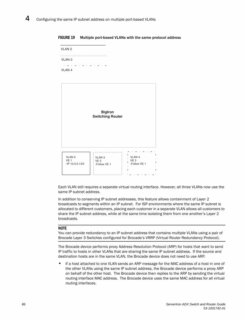
Configuring the same IP subnet address on multiple port-based VLANs4DRAFT: BROCADE CONFIDENTIAL
FIGURE 19 Multiple port-based VLANs with the same protocol address
Each VLAN still requires a separate virtual routing interface. However, all three VLANs now use the same IP subnet address.
In addition to conserving IP subnet addresses, this feature allows containment of Layer 2 broadcasts to segments within an IP subnet. For ISP environments where the same IP subnet is allocated to different customers, placing each customer in a separate VLAN allows all customers to share the IP subnet address, while at the same time isolating them from one another’s Layer 2 broadcasts.
NOTEYou can provide redundancy to an IP subnet address that contains multiple VLANs using a pair of Brocade Layer 3 Switches configured for Brocade’s VRRP (Virtual Router Redundancy Protocol).
The Brocade device performs proxy Address Resolution Protocol (ARP) for hosts that want to send IP traffic to hosts in other VLANs that are sharing the same IP subnet address. If the source and destination hosts are in the same VLAN, the Brocade device does not need to use ARP.
• If a host attached to one VLAN sends an ARP message for the MAC address of a host in one of the other VLANs using the same IP subnet address, the Brocade device performs a proxy ARP on behalf of the other host. The Brocade device then replies to the ARP by sending the virtual routing interface MAC address. The Brocade device uses the same MAC address for all virtual routing interfaces.
VLAN 2
VLAN 3
VLAN 4
BigIronSwitching Router
VLAN 2VE 1-IP 10.0.0.1/24
VLAN 3VE 2-Follow VE 1
VLAN 4VE 3-Follow VE 1
86 ServerIron ADX Switch and Router Guide53-1001742-01

Configuring the same IP subnet address on multiple port-based VLANs 4DRAFT: BROCADE CONFIDENTIAL
When the host that sent the ARP then sends a unicast packet addressed to the virtual routing interface’s MAC address, the device switches the packet on Layer 3 to the destination host on the VLAN.
NOTEIf the Brocade device’s ARP table does not contain the requested host, the Brocade device forwards the ARP request on Layer 2 to the same VLAN as the one that received the ARP request. Then the device sends an ARP for the destination to the other VLANs that are using the same IP subnet address.
• If the destination is in the same VLAN as the source, the Brocade device does not need to perform a proxy ARP.
To configure multiple VLANs to use the same IP subnet address:
• Configure each VLAN, including adding tagged or untagged ports.
• Configure a separate virtual routing interface for each VLAN, but do not add an IP subnet address to more than one of the virtual routing interfaces.
• Configure the virtual routing interfaces that do not have the IP subnet address to “follow” the virtual routing interface that does have the address.
To configure the VLANs shown in Figure 19, you could enter the following commands.
ServerIron(config)# vlan 1 by portServerIron(config-vlan-1)# untag ethernet 1/1ServerIron(config-vlan-1)# tag ethernet 1/8ServerIron(config-vlan-1)# router-interface ve 1
Syntax: ip follow ve <num>
The commands above configure port-based VLAN 1. The VLAN has one untagged port (1/1) and a tagged port (1/8). In this example, all three VLANs contain port 1/8 so the port must be tagged to allow the port to be in multiple VLANs. You can configure VLANs to share a Layer 3 protocol interface regardless of tagging. A combination of tagged and untagged ports is shown in this example to demonstrate that sharing the interface does not change other VLAN features.
Notice that each VLAN still requires a unique virtual routing interface.
The following commands configure port-based VLANs 2 and 3.
ServerIron(config-vlan-1)# vlan 2 by portServerIron(config-vlan-2)# untag ethernet 1/2ServerIron(config-vlan-2)# tag ethernet 1/8ServerIron(config-vlan-2)# router-interface ve 2ServerIron(config-vlan-2)# vlan 3 by portServerIron(config-vlan-3)# untag ethernet 1/5 to 1/6ServerIron(config-vlan-3)# tag ethernet 1/8ServerIron(config-vlan-3)# router-interface ve 3
The following commands configure an IP subnet address on virtual routing interface 1.
ServerIron(config-vlan-3)# interface ve 1ServerIron(config-vif-1)# ip address 10.0.0.1/24
The following commands configure virtual routing interfaces 2 and 3 to “follow” the IP subnet address configured on virtual routing interface 1.
ServerIron ADX Switch and Router Guide 8753-1001742-01
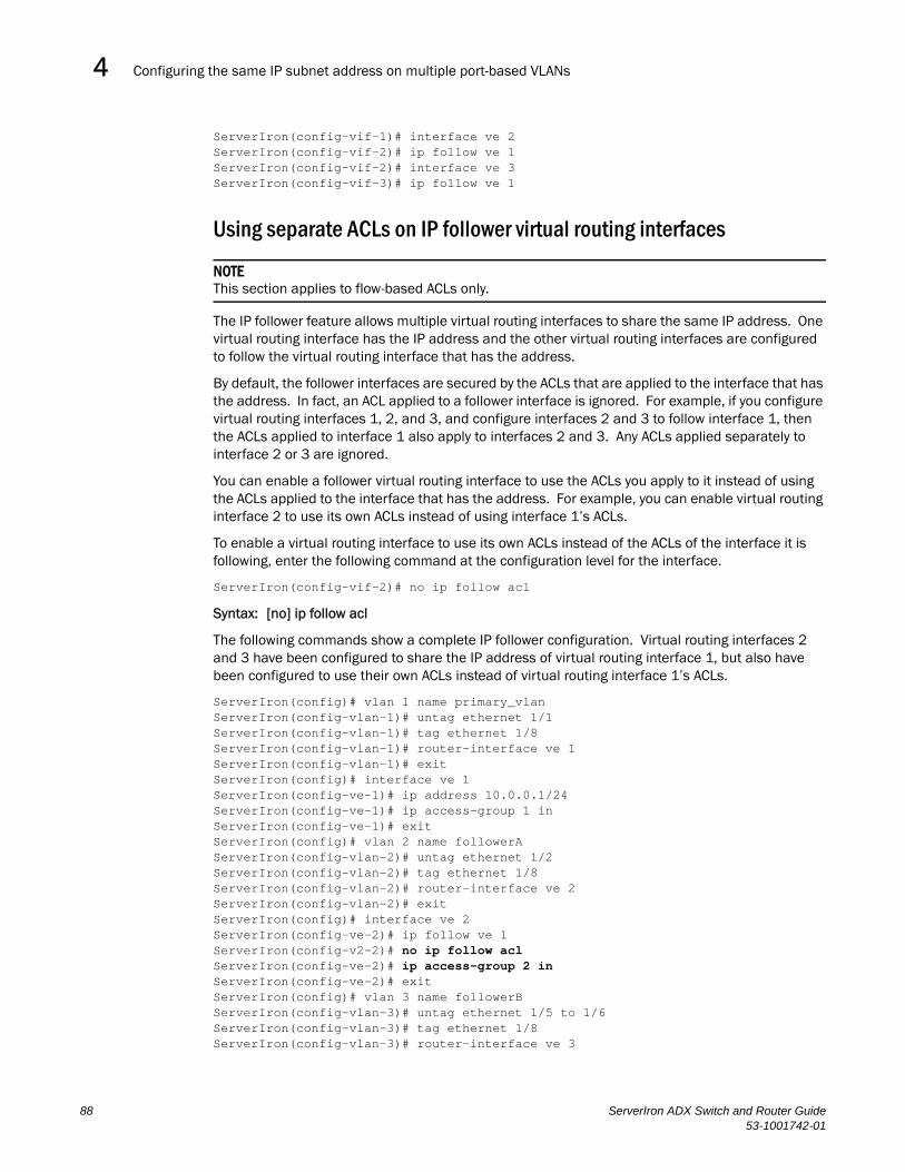
Configuring the same IP subnet address on multiple port-based VLANs4DRAFT: BROCADE CONFIDENTIAL
ServerIron(config-vif-1)# interface ve 2ServerIron(config-vif-2)# ip follow ve 1ServerIron(config-vif-2)# interface ve 3ServerIron(config-vif-3)# ip follow ve 1
Using separate ACLs on IP follower virtual routing interfaces
NOTEThis section applies to flow-based ACLs only.
The IP follower feature allows multiple virtual routing interfaces to share the same IP address. One virtual routing interface has the IP address and the other virtual routing interfaces are configured to follow the virtual routing interface that has the address.
By default, the follower interfaces are secured by the ACLs that are applied to the interface that has the address. In fact, an ACL applied to a follower interface is ignored. For example, if you configure virtual routing interfaces 1, 2, and 3, and configure interfaces 2 and 3 to follow interface 1, then the ACLs applied to interface 1 also apply to interfaces 2 and 3. Any ACLs applied separately to interface 2 or 3 are ignored.
You can enable a follower virtual routing interface to use the ACLs you apply to it instead of using the ACLs applied to the interface that has the address. For example, you can enable virtual routing interface 2 to use its own ACLs instead of using interface 1’s ACLs.
To enable a virtual routing interface to use its own ACLs instead of the ACLs of the interface it is following, enter the following command at the configuration level for the interface.
ServerIron(config-vif-2)# no ip follow acl
Syntax: [no] ip follow acl
The following commands show a complete IP follower configuration. Virtual routing interfaces 2 and 3 have been configured to share the IP address of virtual routing interface 1, but also have been configured to use their own ACLs instead of virtual routing interface 1’s ACLs.
ServerIron(config)# vlan 1 name primary_vlanServerIron(config-vlan-1)# untag ethernet 1/1ServerIron(config-vlan-1)# tag ethernet 1/8ServerIron(config-vlan-1)# router-interface ve 1ServerIron(config-vlan-1)# exitServerIron(config)# interface ve 1ServerIron(config-ve-1)# ip address 10.0.0.1/24ServerIron(config-ve-1)# ip access-group 1 inServerIron(config-ve-1)# exitServerIron(config)# vlan 2 name followerAServerIron(config-vlan-2)# untag ethernet 1/2ServerIron(config-vlan-2)# tag ethernet 1/8ServerIron(config-vlan-2)# router-interface ve 2ServerIron(config-vlan-2)# exitServerIron(config)# interface ve 2ServerIron(config-ve-2)# ip follow ve 1ServerIron(config-v2-2)# no ip follow aclServerIron(config-ve-2)# ip access-group 2 inServerIron(config-ve-2)# exitServerIron(config)# vlan 3 name followerBServerIron(config-vlan-3)# untag ethernet 1/5 to 1/6ServerIron(config-vlan-3)# tag ethernet 1/8ServerIron(config-vlan-3)# router-interface ve 3
88 ServerIron ADX Switch and Router Guide53-1001742-01
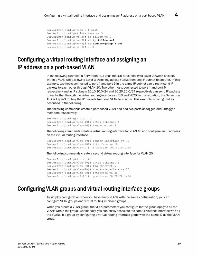
Configuring a virtual routing interface and assigning an IP address on a port-based VLAN 4DRAFT: BROCADE CONFIDENTIAL
ServerIron(config-vlan-3)# exitServerIron(config)# interface ve 3ServerIron(config-ve-3)# ip follow ve 1ServerIron(config-ve-3)# no ip follow aclServerIron(config-ve-3)# ip access-group 3 outServerIron(config-ve-3)# exit
Configuring a virtual routing interface and assigning an IP address on a port-based VLAN
In the following example, a ServerIron ADX uses the ISR functionality to Layer-2 switch packets within a VLAN while allowing Layer 3 switching across VLANs from one IP subnet to another. In this example, two hosts connected to port 4 and port 5 in the same IP subnet can directly send IP packets to each other through VLAN 10. Two other hosts connected to port 4 and port 6 respectively and in IP subnets 10.10.10.0/24 and 20.20.20.0/24 respectively can send IP packets to each other through the virtual routing interfaces VE10 and VE20. In this situation, the ServerIron ADX is Layer-3 routing the IP packets from one VLAN to another. This example is configured as described in the following.
The following commands create a port-based VLAN and add two ports as tagged and untagged members respectively.
ServerIron(config)# vlan 10ServerIron(config-vlan-10)# untag ethernet 4ServerIron(config-vlan-10)# tag ethernet 5
The following commands create a virtual routing interface for VLAN 10 and configure an IP address on the virtual routing interface.
ServerIron(config-vlan-10)# router-interface ve 10ServerIron(config-vlan-10)# interface ve 10ServerIron(config-vif-10)# ip address 10.10.10.1/24
The following commands create a second virtual routing interface for VLAN 20.
ServerIron(config)# vlan 20ServerIron(config-vlan-20)# untag ethernet 6ServerIron(config-vlan-20)# tag ethernet 5ServerIron(config-vlan-20)# router-interface ve 20ServerIron(config-vlan-20)# interface ve 20ServerIron(config-vif-20)# ip address 20.20.20.1/24
Configuring VLAN groups and virtual routing interface groupsTo simplify configuration when you have many VLANs with the same configuration, you can configure VLAN groups and virtual routing interface groups.
When you create a VLAN group, the VLAN parameters you configure for the group apply to all the VLANs within the group. Additionally, you can easily associate the same IP subnet interface with all the VLANs in a group by configuring a virtual routing interface group with the same ID as the VLAN group:
ServerIron ADX Switch and Router Guide 8953-1001742-01

Configuring VLAN groups and virtual routing interface groups4DRAFT: BROCADE CONFIDENTIAL
• The VLAN group feature allows you to create multiple port-based VLANs with identical port members. Since the member ports are shared by all the VLANs within the group, you must add the ports as tagged ports. This feature not only simplifies VLAN configuration but also allows you to have a large number of identically configured VLANs in a startup-config file on the device’s flash memory module. Normally, a startup-config file with a large number of VLANs might not fit on the flash memory module. By grouping the identically configured VLANs, you can conserve space in the startup-config file so that it fits on the flash memory module.
• The virtual routing interface group feature is useful when you want to configure the same IP subnet address on all the port-based VLANs within a VLAN group. You can configure a virtual routing interface group only after you configure a VLAN group with the same ID. The virtual routing interface group automatically applies to the VLANs in the VLAN group that has the same ID and cannot be applied to other VLAN groups or to individual VLANs.
You can create up to 32 VLAN groups and 32 virtual routing interface groups. A virtual routing interface group always applies only to the VLANs in the VLAN group with the same ID.
NOTEDepending on the size of the VLAN ID range you want to use for the VLAN group, you might need to allocate additional memory for VLANs. On Layer 3 Switches, if you allocate additional memory for VLANs, you also need to allocate the same amount of memory for virtual routing interfaces. This is true regardless of whether you use the virtual routing interface groups. To allocate additional memory, refer to “Allocating memory for more VLANs or virtual routing interfaces” on page 93.
Configuring a VLAN groupTo configure a VLAN group, use the following CLI method.
To configure a VLAN group, enter commands such as the following.
ServerIron(config)# vlan-group 1 vlan 2 to 46ServerIron(config-vlan-group-1)# tagged 1/1 to 1/2
The first command in this example begins configuration for VLAN group 1, and assigns VLANs 2 through 46 to the group. The second command adds ports 1/1 and 1/2 as tagged ports. Since all the VLANs in the group share the ports, you must add the ports as tagged ports.
Syntax: vlan-group <num> vlan <vlan-id> to <vlan-id>
Syntax: tagged ethernet | pos <portnum> [to <portnum> | ethernet <portnum>]
The <num> parameter with the vlan-group command specifies the VLAN group ID and can be from 1 – 32. The vlan <vlan-id> to <vlan-id> parameters specify a contiguous range (a range with no gaps) of individual VLAN IDs. Specify the low VLAN ID first and the high VLAN ID second. The command adds all the specified VLANs to the VLAN group.
NOTEThe maximum number of VLANs that can be assigned to a group is 64.
NOTEThe device’s memory must be configured to contain at least the number of VLANs you specify for the higher end of the range. For example, if you specify 2048 as the VLAN ID at the high end of the range, you first must increase the memory allocation for VLANs to 2048 or higher. Additionally, on Layer 3 Switches, if you allocate additional memory for VLANs, you also need to allocate the same
90 ServerIron ADX Switch and Router Guide53-1001742-01

Configuring VLAN groups and virtual routing interface groups 4DRAFT: BROCADE CONFIDENTIAL
amount of memory for virtual routing interfaces, before you configure the VLAN groups. This is true regardless of whether you use the virtual routing interface groups. The memory allocation is required because the VLAN groups and virtual routing interface groups have a one-to-one mapping. Refer to “Allocating memory for more VLANs or virtual routing interfaces” on page 93.
If a VLAN within the range you specify is already configured, the CLI does not add the group but instead displays an error message. In this case, create the group by specifying a valid contiguous range. Then add more VLANs to the group after the CLI changes to the configuration level for the group. See the following example.
You can add and remove individual VLANs or VLAN ranges from at the VLAN group configuration level. For example, if you want to add VLANs 1001 and 1002 to VLAN group 1 and remove VLANs 90 through 50, enter the following commands.
ServerIron(config-vlan-group-1)# add-vlan 1001 to 1002ServerIron(config-vlan-group-1)# remove-vlan 90 to 50
Syntax: add-vlan <vlan-id> [to <vlan-id>]
Syntax: remove-vlan <vlan-id> [to <vlan-id>]
Displaying information about VLAN groups
To display VLAN group configuration information, enter the following command.
ServerIron# show vlan-groupvlan-group 1 vlan 2 to 20 tagged ethe 1/1 to 1/2 !vlan-group 2 vlan 21 to 40 tagged ethe 1/1 to 1/2 !
Syntax: show vlan-group [<group-id>]
This example shows configuration information for two VLAN groups, group 1 and group 2.
The <group-id> specifies a VLAN group. If you do not use this parameter, the configuration information for all the configured VLAN groups is displayed.
Configuring a virtual routing interface groupA virtual routing interface group allows you to associate the same IP subnet interface with multiple port-based VLANs. For example, if you associate a virtual routing interface group with a VLAN group, all the VLANs in the group have the IP interface of the virtual routing interface group.
To configure a virtual routing interface group, use the following CLI method.
NOTEWhen you configure a virtual routing interface group, all members of the group have the same IP subnet address. This feature is useful in collocation environments where the device has many IP addresses and you want to conserve the IP address space.
To configure a virtual routing interface group, enter commands such as the following.
ServerIron ADX Switch and Router Guide 9153-1001742-01

Configuring VLAN groups and virtual routing interface groups4DRAFT: BROCADE CONFIDENTIAL
ServerIron(config)# vlan-group 1ServerIron(config-vlan-group-1)# group-router-interfaceServerIron(config-vlan-group-1)# exitServerIron(config)# interface group-ve 1ServerIron(config-vif-group-1)# ip address 10.10.10.1/24These commands enable VLAN group 1 to have a group virtual routing interface, then configure virtual routing interface group 1. The software always associates a virtual routing interface group only with the VLAN group that has the same ID. In this example, the VLAN group ID is 1, so the corresponding virtual routing interface group also must have ID 1.
Syntax: group-router-interface
Syntax: interface group-ve <num>
Syntax: [no] ip address <ip-addr> <ip-mask> [secondary]
or
Syntax: [no] ip address <ip-addr>/<mask-bits> [secondary]
The router-interface-group command enables a VLAN group to use a virtual routing interface group. Enter this command at the configuration level for the VLAN group. This command configures the VLAN group to use the virtual routing interface group that has the same ID as the VLAN group. You can enter this command when you configure the VLAN group for the first time or later, after you have added tagged ports to the VLAN and so on.
The <num> parameter in the interface group-ve <num> command specifies the ID of the VLAN group with which you want to associate this virtual routing interface group. The VLAN group must already be configured and enabled to use a virtual routing interface group. The software automatically associates the virtual routing interface group with the VLAN group that has the same ID. You can associate a virtual routing interface group only with the VLAN group that has the same ID.
NOTEIf the system max for virtual interface is set to 512, then a virtual interface(VE) with ID greater than 512 can not be created by the system. When creating group-router-interface, the ID is picked automatically to be equal to smallest VLAN ID in the vlan-group. If it happens to be greater than 512 then virtual routing interface group creation will fail.
The syntax and usage for the ip address command is the same as when you use the command at the interface level to add an IP interface.
Displaying the VLAN group and virtual routing interface group informationTo verify configuration of VLAN groups and virtual routing interface groups, display the running-config file. If you have saved the configuration to the startup-config file, you also can verify the configuration by displaying the startup-config file. The following example shows the running-config information for the VLAN group and virtual routing interface group configured in the previous examples. The information appears in the same way in the startup-config file.
ServerIron(config)# show running-config
lines not related to the VLAN group omitted...
vlan-group 1 vlan 2 to 44 add-vlan 1001 to 1002
92 ServerIron ADX Switch and Router Guide53-1001742-01

Configuring VLAN groups and virtual routing interface groups 4DRAFT: BROCADE CONFIDENTIAL
tagged ethe 1/1 to 1/2 router-interface-group
lines not related to the virtual routing interface group omitted...
interface group-ve 1 ip address 10.10.10.1 255.255.255.0
NOTEIf you have enabled display of subnet masks in CIDR notation, the IP address information is shown as follows: 10.10.10.1/24.
Allocating memory for more VLANs or virtual routing interfacesA ServerIron ADX can support up to 4095 VLANs and 4095 virtual routing interfaces.
The number of VLANs and virtual routing interfaces supported on your product depends on the device lists the default and configurable maximum numbers of VLANs and virtual routing interfaces for Layer 3 Switches and Layer 2 Switches. Unless otherwise noted, the values apply to both types of switches.
Increasing the number of VLANs you can configure
To increase the size of the VLAN table, which determines how many VLANs you can configure, use either of the following methods.
NOTEAlthough you can specify up to 4095 VLANs, you can configure only 4094 VLANs. VLAN ID 4094 is reserved for use by the Single Spanning Tree feature.
To increase the maximum number of VLANs you can configure, enter commands such as the following at the global CONFIG level of the CLI.
ServerIron(config)# system-max vlan 2048ServerIron(config)# write memoryServerIron(config)# endServerIron# reload
Syntax: system-max vlan <num>
The <num> parameter indicates the maximum number of VLANs.
Increasing the number of virtual routing interfaces you can configure
To increase the size of the virtual routing interface table, which determines how many virtual routing interfaces you can configure, the following method.
To increase the maximum number of virtual routing interfaces you can configure, enter commands such as the following at the global CONFIG level of the CLI.
ServerIron(config)# system-max virtual-interface 4095ServerIron(config)# write memoryServerIron(config)# endServerIron# reload
ServerIron ADX Switch and Router Guide 9353-1001742-01

Configuring super aggregated VLANs4DRAFT: BROCADE CONFIDENTIAL
Syntax: system-max virtual-interface <num>
The <num> parameter indicates the maximum number of virtual routing interfaces.
Configuring super aggregated VLANsYou can aggregate multiple VLANs within another VLAN. This feature allows you to construct Layer 2 paths and channels. This feature is particularly useful for Virtual Private Network (VPN) applications in which you need to provide a private, dedicated Ethernet connection for an individual client to transparently reach its subnet across multiple networks.
Conceptually, the paths and channels are similar to Asynchronous Transfer Mode (ATM) paths and channels. A path contains multiple channels, each of which is a dedicated circuit between two end points. The two devices at the end points of the channel appear to each other to be directly attached. The network that connects them is transparent to the two devices.
You can aggregate up to 4094 VLANs within another VLAN. This provides a total VLAN capacity on one Brocade device of 16,760,836 channels (4094 * 4094).
The devices connected through the channel are not visible to devices in other channels. Therefore, each client has a private link to the other side of the channel.
The feature allows point-to-point and point-to-multipoint connections.
Figure 20 shows a conceptual picture of the service that aggregated VLANs provide. Aggregated VLANs provide a path for multiple client channels. The channels do not receive traffic from other channels. Thus, each channel is a private link.
94 ServerIron ADX Switch and Router Guide53-1001742-01

Configuring super aggregated VLANs 4DRAFT: BROCADE CONFIDENTIAL
FIGURE 20 Conceptual Model of the Super Aggregated VLAN Application
Each client connected to the edge device is in its own port-based VLAN, which is like an ATM channel. All the clients’ VLANs are aggregated by the edge device into a single VLAN for connection to the core. The single VLAN that aggregates the clients’ VLANs is like an ATM path.
The device that aggregates the VLANs forwards the aggregated VLAN traffic through the core. The core can consist of multiple devices that forward the aggregated VLAN traffic. The edge device at the other end of the core separates the aggregated VLANs into the individual client VLANs before forwarding the traffic. The edge devices forward the individual client traffic to the clients. For the clients’ perspective, the channel is a direct point-to-point link.
Figure 21 shows an example application that uses aggregated VLANs. This configuration includes the client connections shown in Figure 20.
Client 1 Client 3 Client 5. . . . . .
Client 1192.168.1.69/24
Path = a single VLAN into whichclient VLANs are aggregated
Channel = a client VLAN nestedinside a Path
sub-net192.168.1.0/24
ServerIron ADX Switch and Router Guide 9553-1001742-01
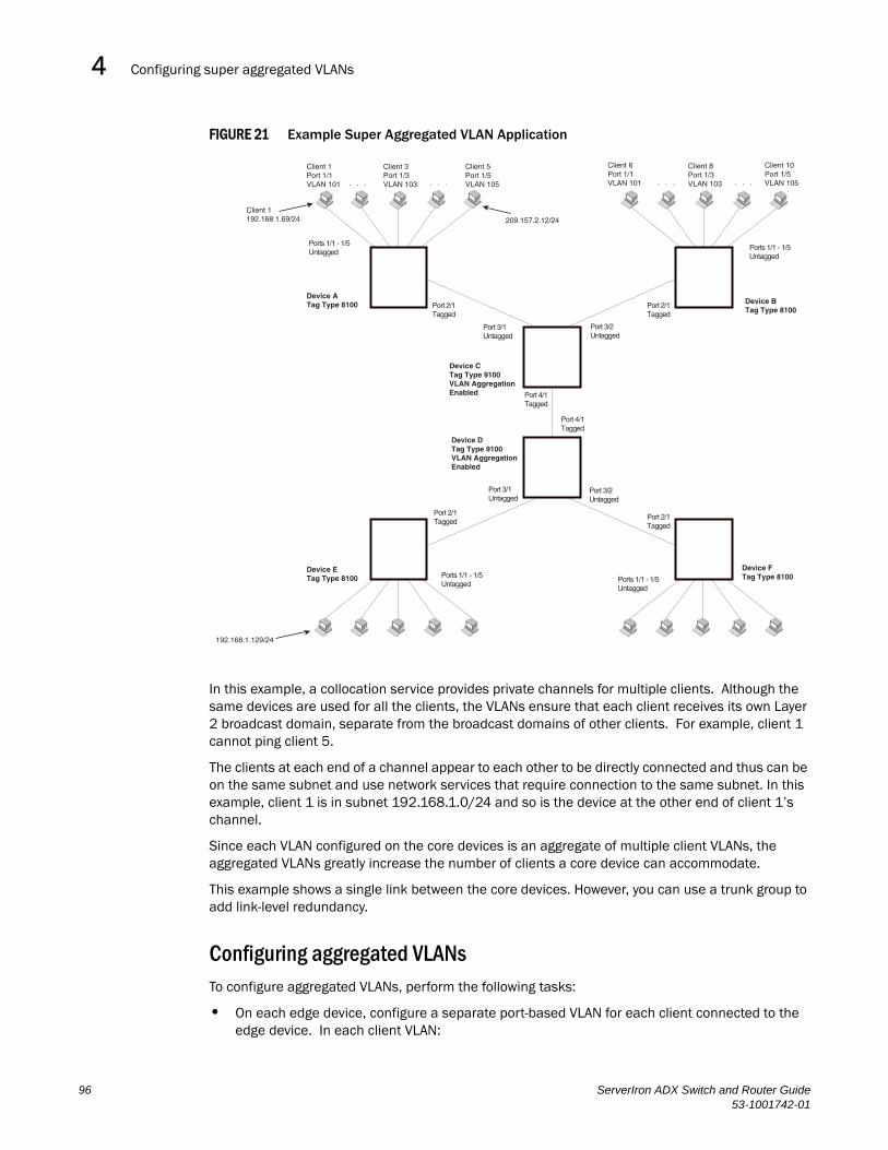
Configuring super aggregated VLANs4DRAFT: BROCADE CONFIDENTIAL
FIGURE 21 Example Super Aggregated VLAN Application
In this example, a collocation service provides private channels for multiple clients. Although the same devices are used for all the clients, the VLANs ensure that each client receives its own Layer 2 broadcast domain, separate from the broadcast domains of other clients. For example, client 1 cannot ping client 5.
The clients at each end of a channel appear to each other to be directly connected and thus can be on the same subnet and use network services that require connection to the same subnet. In this example, client 1 is in subnet 192.168.1.0/24 and so is the device at the other end of client 1’s channel.
Since each VLAN configured on the core devices is an aggregate of multiple client VLANs, the aggregated VLANs greatly increase the number of clients a core device can accommodate.
This example shows a single link between the core devices. However, you can use a trunk group to add link-level redundancy.
Configuring aggregated VLANsTo configure aggregated VLANs, perform the following tasks:
• On each edge device, configure a separate port-based VLAN for each client connected to the edge device. In each client VLAN:
Client 1Port 1/1VLAN 101
Client 3Port 1/3VLAN 103
Client 5Port 1/5VLAN 105 . . .. . .
Client 1192.168.1.69/24 209.157.2.12/24
Client 6Port 1/1VLAN 101
Client 8Port 1/3VLAN 103
Client 10Port 1/5VLAN 105 . . . . . .
Ports 1/1 - 1/5Untagged
Ports 1/1 - 1/5Untagged
Device ATag Type 8100 Port 2/1
TaggedPort 2/1Tagged
Device BTag Type 8100
Port 3/1Untagged
Port 3/2Untagged
Device CTag Type 9100VLAN AggregationEnabled Port 4/1
Tagged
Port 4/1Tagged
Device DTag Type 9100VLAN AggregationEnabled
Port 3/1Untagged
Port 3/2Untagged
Port 2/1Tagged
Port 2/1Tagged
Device ETag Type 8100
Device FTag Type 8100Ports 1/1 - 1/5
UntaggedPorts 1/1 - 1/5Untagged
192.168.1.129/24
96 ServerIron ADX Switch and Router Guide53-1001742-01

Configuring super aggregated VLANs 4DRAFT: BROCADE CONFIDENTIAL
• Add the port connected to the client as an untagged port.
• Add the port connected to the core device (the device that will aggregate the VLANs) as a tagged port. This port must be tagged because all the client VLANs share the port as an uplink to the core device.
• On each core device:
• Enable VLAN aggregation. This support allows the core device to add an additional tag to each Ethernet frame that contains a VLAN packet from the edge device. The additional tag identifies the aggregate VLAN (the path). However, the additional tag can cause the frame to be longer than the maximum supported frame size. The larger frame support allows Ethernet frames up to 1530 bytes long.
NOTEEnable the VLAN aggregation option only on the core devices.
• Configure a VLAN tag type (tag ID) that is different than the tag type used on the edge devices. If you use the default tag type (8100) on the edge devices, set the tag type on the core devices to another value, such as 9100. The tag type must be the same on all the core devices. The edge devices also must have the same tag type but the type must be different from the tag type on the core devices.
NOTEYou can enable the Spanning Tree Protocol (STP) on the edge devices or the core devices, but not both. If you enable STP on the edge devices and the core devices, STP will prevent client traffic from travelling through the core to the other side.
Configuring aggregated VLANs on an edge device
To configure the aggregated VLANs on device A in Figure 21 on page 96, enter the following commands.
ServerIron(config)# vlan 101 by portServerIron(config-vlan-101)# tagged ethernet 2/1ServerIron(config-vlan-101)# untagged ethernet 1/1ServerIron(config-vlan-101)# exitServerIron(config)# vlan 102 by portServerIron(config-vlan-102)# tagged ethernet 2/1ServerIron(config-vlan-102)# untagged ethernet 1/2ServerIron(config-vlan-102)# exitServerIron(config)# vlan 103 by portServerIron(config-vlan-103)# tagged ethernet 2/1ServerIron(config-vlan-103)# untagged ethernet 1/3ServerIron(config-vlan-103)# exitServerIron(config)# vlan 104 by portServerIron(config-vlan-104)# tagged ethernet 2/1ServerIron(config-vlan-104)# untagged ethernet 1/4ServerIron(config-vlan-104)# exitServerIron(config)# vlan 105 by portServerIron(config-vlan-105)# tagged ethernet 2/1ServerIron(config-vlan-105)# untagged ethernet 1/5ServerIron(config-vlan-105)# exitServerIron(config)# write memory
Syntax: [no] vlan <vlan-id> [by port]
Syntax: [no] tagged ethernet <portnum> [to <portnum> | ethernet <portnum>]
ServerIron ADX Switch and Router Guide 9753-1001742-01

Configuring super aggregated VLANs4DRAFT: BROCADE CONFIDENTIAL
Syntax: [no] untagged ethernet <portnum> [to <portnum> | ethernet <portnum>]
Use the tagged command to add the port that the device uses for the uplink to the core device. Use the untagged command to add the ports connected to the individual clients.
Configuring aggregated VLANs on a core device
To configure aggregated VLANs on a core device, use the following method.
To configure the aggregated VLANs on device C in Figure 21 on page 96, enter the following commands.
ServerIron(config)# tag-type 9100ServerIron(config)# aggregated-vlanServerIron(config)# vlan 101 by portServerIron(config-vlan-101)# tagged ethernet 4/1ServerIron(config-vlan-101)# untagged ethernet 3/1ServerIron(config-vlan-101)# exitServerIron(config)# vlan 102 by portServerIron(config-vlan-102)# tagged ethernet 4/1ServerIron(config-vlan-102)# untagged ethernet 3/2ServerIron(config-vlan-102)# exitServerIron(config)# write memory
Syntax: [no] tag-type <num>
Syntax: [no] aggregated-vlan
The <num> parameter specifies the tag type can be a hexadecimal value from 0 – ffff. The default is 8100.
Complete CLI examplesThe following sections show all the Aggregated VLAN configuration commands on the devices in Figure 21 on page 96.
NOTEIn these examples, the configurations of the edge devices (A, B, E, and F) are identical. The configurations of the core devices (C and D) also are identical. The aggregated VLAN configurations of the edge and core devices on one side must be symmetrical (in fact, a mirror image) to the configurations of the devices on the other side. For simplicity, the example in Figure 21 on page 96 is symmetrical in terms of the port numbers. This allows the configurations for both sides of the link to be the same. If your configuration does not use symmetrically arranged port numbers, the configurations should not be identical but must use the correct port numbers.
Commands for device AServerIronA(config)# vlan 101 by portServerIronA(config-vlan-101)# tagged ethernet 2/1ServerIronA(config-vlan-101)# untagged ethernet 1/1ServerIronA(config-vlan-101)# exitServerIronA(config)# vlan 102 by portServerIronA(config-vlan-102)# tagged ethernet 2/1ServerIronA(config-vlan-102)# untagged ethernet 1/2ServerIronA(config-vlan-102)# exitServerIronA(config)# vlan 103 by portServerIronA(config-vlan-103)# tagged ethernet 2/1
98 ServerIron ADX Switch and Router Guide53-1001742-01

Configuring super aggregated VLANs 4DRAFT: BROCADE CONFIDENTIAL
ServerIronA(config-vlan-103)# untagged ethernet 1/3ServerIronA(config-vlan-103)# exitServerIronA(config)# vlan 104 by portServerIronA(config-vlan-104)# tagged ethernet 2/1ServerIronA(config-vlan-104)# untagged ethernet 1/4ServerIronA(config-vlan-104)# exitServerIronA(config)# vlan 105 by portServerIronA(config-vlan-105)# tagged ethernet 2/1ServerIronA(config-vlan-105)# untagged ethernet 1/5ServerIronA(config-vlan-105)# exitServerIronA(config)# write memory
Commands for device B
The commands for configuring device B are identical to the commands for configuring device A. Notice that you can use the same channel VLAN numbers on each device. The devices that aggregate the VLANs into a path can distinguish between the identically named channel VLANs based on the ID of the path VLAN.
ServerIronB(config)# vlan 101 by portServerIronB(config-vlan-101)# tagged ethernet 2/1ServerIronB(config-vlan-101)# untagged ethernet 1/1ServerIronB(config-vlan-101)# exitServerIronB(config)# vlan 102 by portServerIronB(config-vlan-102)# tagged ethernet 2/1ServerIronB(config-vlan-102)# untagged ethernet 1/2ServerIronB(config-vlan-102)# exitServerIronB(config)# vlan 103 by portServerIronB(config-vlan-103)# tagged ethernet 2/1ServerIronB(config-vlan-103)# untagged ethernet 1/3ServerIronB(config-vlan-103)# exitServerIronB(config)# vlan 104 by portServerIronB(config-vlan-104)# tagged ethernet 2/1ServerIronB(config-vlan-104)# untagged ethernet 1/4ServerIronB(config-vlan-104)# exitServerIronB(config)# vlan 105 by portServerIronB(config-vlan-105)# tagged ethernet 2/1ServerIronB(config-vlan-105)# untagged ethernet 1/5ServerIronB(config-vlan-105)# exitServerIronB(config)# write memory
Commands for device C
Since device C is aggregating channel VLANs from devices A and B into a single path, you need to change the tag type and enable VLAN aggregation.
ServerIronC(config)# tag-type 9100ServerIronC(config)# aggregated-vlanServerIronC(config)# vlan 101 by portServerIronC(config-vlan-101)# tagged ethernet 4/1ServerIronC(config-vlan-101)# untagged ethernet 3/1ServerIronC(config-vlan-101)# exitServerIronC(config)# vlan 102 by portServerIronC(config-vlan-102)# tagged ethernet 4/1ServerIronC(config-vlan-102)# untagged ethernet 3/2ServerIronC(config-vlan-102)# exitServerIronC(config)# write memory
ServerIron ADX Switch and Router Guide 9953-1001742-01

Configuring super aggregated VLANs4DRAFT: BROCADE CONFIDENTIAL
Commands for device D
Device D is at the other end of path and separates the channels back into individual VLANs. The tag type must be the same as tag type configured on the other core device (Device C). In addition, VLAN aggregation also must be enabled.
ServerIronD(config)# tag-type 9100ServerIronD(config)# aggregated-vlanServerIronD(config)# vlan 101 by portServerIronD(config-vlan-101)# tagged ethernet 4/1ServerIronD(config-vlan-101)# untagged ethernet 3/1ServerIronD(config-vlan-101)# exitServerIronD(config)# vlan 102 by portServerIronD(config-vlan-102)# tagged ethernet 4/1ServerIronD(config-vlan-102)# untagged ethernet 3/2ServerIronD(config-vlan-102)# exitServerIronD(config)# write memory
Commands for device E
Since the configuration in Figure 21 on page 96 is symmetrical, the commands for configuring device E are identical to the commands for configuring device A.
ServerIronE(config)# vlan 101 by portServerIronE(config-vlan-101)# tagged ethernet 2/1ServerIronE(config-vlan-101)# untagged ethernet 1/1ServerIronE(config-vlan-101)# exitServerIronE(config)# vlan 102 by portServerIronE(config-vlan-102)# tagged ethernet 2/1ServerIronE(config-vlan-102)# untagged ethernet 1/2ServerIronE(config-vlan-102)# exitServerIronE(config)# vlan 103 by portServerIronE(config-vlan-103)# tagged ethernet 2/1ServerIronE(config-vlan-103)# untagged ethernet 1/3ServerIronE(config-vlan-103)# exitServerIronE(config)# vlan 104 by portServerIronE(config-vlan-104)# tagged ethernet 2/1ServerIronE(config-vlan-104)# untagged ethernet 1/4ServerIronE(config-vlan-104)# exitServerIronE(config)# vlan 105 by portServerIronE(config-vlan-105)# tagged ethernet 2/1ServerIronE(config-vlan-105)# untagged ethernet 1/5ServerIronE(config-vlan-105)# exitServerIronE(config)# write memory
Commands for device F
The commands for configuring device F are identical to the commands for configuring device E. In this example, since the port numbers on each side of the configuration in Figure 21 on page 96 are symmetrical, the configuration of device F is also identical to the configuration of device A and device B.
ServerIronF(config)# vlan 101 by portServerIronF(config-vlan-101)# tagged ethernet 2/1ServerIronF(config-vlan-101)# untagged ethernet 1/1ServerIronF(config-vlan-101)# exitServerIronF(config)# vlan 102 by portServerIronF(config-vlan-102)# tagged ethernet 2/1
100 ServerIron ADX Switch and Router Guide53-1001742-01

Dual-mode VLAN ports 4DRAFT: BROCADE CONFIDENTIAL
ServerIronF(config-vlan-102)# untagged ethernet 1/2ServerIronF(config-vlan-102)# exitServerIronF(config)# vlan 103 by portServerIronF(config-vlan-103)# tagged ethernet 2/1ServerIronF(config-vlan-103)# untagged ethernet 1/3ServerIronF(config-vlan-103)# exitServerIronF(config)# vlan 104 by portServerIronF(config-vlan-104)# tagged ethernet 2/1ServerIronF(config-vlan-104)# untagged ethernet 1/4ServerIronF(config-vlan-104)# exitServerIronF(config)# vlan 105 by portServerIronF(config-vlan-105)# tagged ethernet 2/1ServerIronF(config-vlan-105)# untagged ethernet 1/5ServerIronF(config-vlan-105)# exitServerIronF(config)# write memory
Dual-mode VLAN portsConfiguring a tagged port as a dual-mode port allows it to accept and transmit both tagged traffic and untagged traffic at the same time. A dual-mode port accepts and transmits frames belonging to VLANs configured for the port, as well as frames belonging to the default VLAN (that is, untagged traffic).
For example, in Figure 22, port 2/11 is a dual-mode port belonging to VLAN 20. Traffic for VLAN 20, as well as traffic for the default VLAN, flows from a hubs to this port. The dual-mode feature allows traffic for VLAN 20 and untagged traffic to go through the port at the same time.
ServerIron ADX Switch and Router Guide 10153-1001742-01
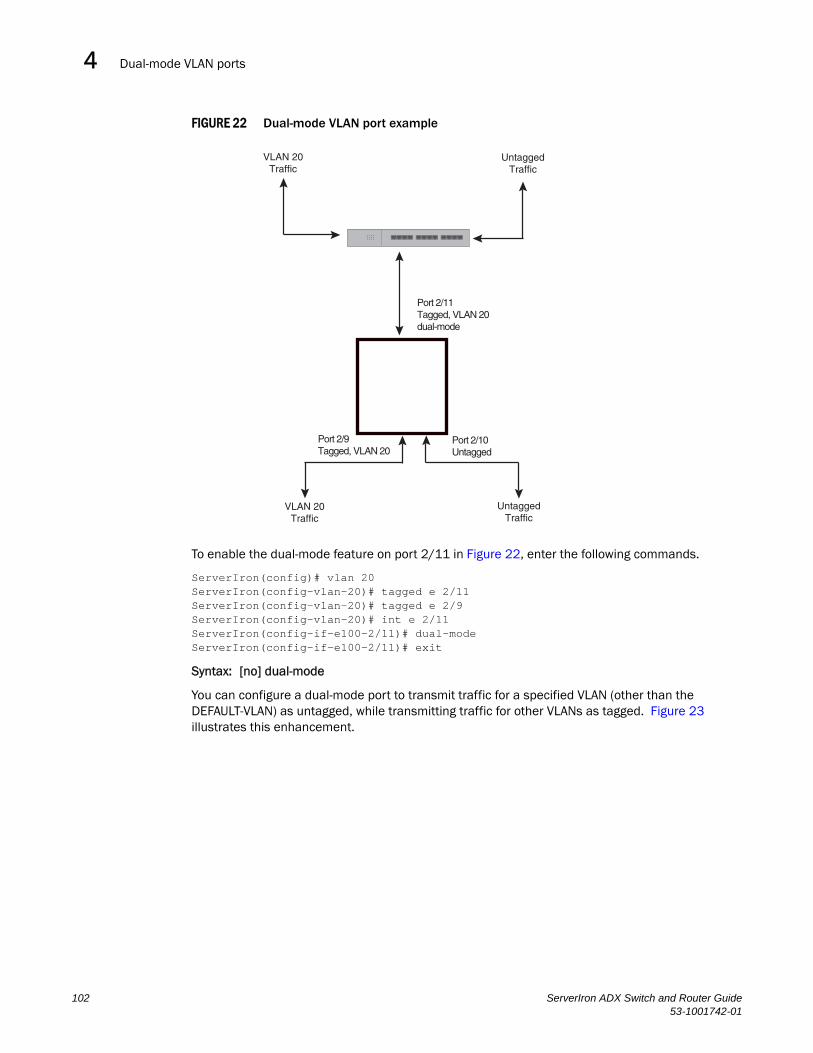
Dual-mode VLAN ports4DRAFT: BROCADE CONFIDENTIAL
FIGURE 22 Dual-mode VLAN port example
To enable the dual-mode feature on port 2/11 in Figure 22, enter the following commands.
ServerIron(config)# vlan 20ServerIron(config-vlan-20)# tagged e 2/11ServerIron(config-vlan-20)# tagged e 2/9ServerIron(config-vlan-20)# int e 2/11ServerIron(config-if-e100-2/11)# dual-modeServerIron(config-if-e100-2/11)# exit
Syntax: [no] dual-mode
You can configure a dual-mode port to transmit traffic for a specified VLAN (other than the DEFAULT-VLAN) as untagged, while transmitting traffic for other VLANs as tagged. Figure 23 illustrates this enhancement.
VLAN 20Traffic
UntaggedTraffic
Port 2/11Tagged, VLAN 20dual-mode
Port 2/9Tagged, VLAN 20
Port 2/10Untagged
VLAN 20Traffic
UntaggedTraffic
102 ServerIron ADX Switch and Router Guide53-1001742-01

Dual-mode VLAN ports 4DRAFT: BROCADE CONFIDENTIAL
FIGURE 23 Specifying a default VLAN ID for a dual-mode port
In Figure 23, tagged port 2/11 is a dual-mode port belonging to VLANs 10 and 20. The default VLAN assigned to this dual-mode port is 10. This means that the port transmits tagged traffic on VLAN 20 (and all other VLANs to which the port belongs) and transmits untagged traffic on VLAN 10.
The dual-mode feature allows tagged traffic for VLAN 20 and untagged traffic for VLAN 10 to go through port 2/11 at the same time. A dual-mode port transmits only untagged traffic on its default VLAN (that is, either VLAN 1, or a user-specified VLAN ID), and only tagged traffic on all other VLANs.
The following commands configure VLANs 10 and 20 in Figure 23. Tagged port 2/11 is added to VLANs 10 and 20, then designated a dual-mode port whose specified default VLAN is 10. In this configuration, port 2/11 transmits only untagged traffic on VLAN 10 and only tagged traffic on VLAN 20.
ServerIron(config)# vlan 10 by portServerIron(config-vlan-10)# untagged e 2/10ServerIron(config-vlan-10)# tagged e 2/11ServerIron(config-vlan-10)# exitServerIron(config)# vlan 20 by portServerIron(config-vlan-20)# tagged e 2/9ServerIron(config-vlan-20)# tagged e 2/11ServerIron(config-vlan-20)# exitServerIron(config)# int e 2/11ServerIron(config-if-e100-2/11)# dual-mode 10ServerIron(config-if-e100-2/11)# exit
Syntax: [no] dual-mode [<vlan-id>]
Notes:
• If you do not specify a <vlan-id> in the dual mode command, the port’s default VLAN is set to 1. The port transmits untagged traffic on the DEFAULT-VLAN.
• The dual-mode feature is disabled by default. Only tagged ports can be configured as dual-mode ports.
• In trunk group, either all of the ports must be dual-mode, or none of them can be.
VLAN 10Untagged
Traffic
VLAN 10Untagged
Traffic
VLAN 10Untagged
Traffic
VLAN 10Untagged
Traffic
VLAN 20TaggedTraffic
VLAN 20TaggedTraffic
Dual-mode Port 2/11Default VLAN ID 10Tagged, VLAN 20
Port 2/10Untagged, VLAN 10
Port 2/9Tagged, VLAN 20
ServerIron ADX Switch and Router Guide 10353-1001742-01

Displaying VLAN information4DRAFT: BROCADE CONFIDENTIAL
The show vlan command displays a separate row for dual-mode ports on each VLAN. For example:
Displaying VLAN informationAfter you configure the VLANs, you can verify the configuration using the following methods.
NOTEIf a VLAN name begins with “GVRP_VLAN_“, the VLAN was created by the GARP VLAN Registration Protocol (GVRP). If a VLAN name begins with “STATIC_VLAN_“, the VLAN was created by GVRP and then was converted into a statically configured VLAN.
Displaying system-wide VLAN informationUse one of the following methods to display VLAN information for all the VLANs configured on the device.
Enter the following command at any CLI level. This example shows the display for the IP subnet and IPX network VLANs configured in the examples in “Configuring an IP subnet VLAN with dynamic ports” on page 84.
ServerIron(config)# show vlanTotal PORT-VLAN entries: 3Maximum PORT-VLAN entries: 16
legend: [S=Slot]
PORT-VLAN 1, Name DEFAULT-VLAN, Priority level0, Spanning tree Off Untagged Ports: (S1) 1 2 3 4 5 6 7 8 Untagged Ports: (S2) 1 2 3 4 5 6 7 8 12 13 14 15 16 17 18 19 Untagged Ports: (S2) 20 21 22 23 24 Tagged Ports: None Uplink Ports: None DualMode Ports: NonePORT-VLAN 10, Name [None], Priority level0, Spanning tree Off Untagged Ports: (S2) 10 Tagged Ports: None Uplink Ports: None DualMode Ports: (S2) 11PORT-VLAN 20, Name [None], Priority level0, Spanning tree Off Untagged Ports: None Tagged Ports: (S2) 9 Uplink Ports: None DualMode Ports: (S2) 11
104 ServerIron ADX Switch and Router Guide53-1001742-01
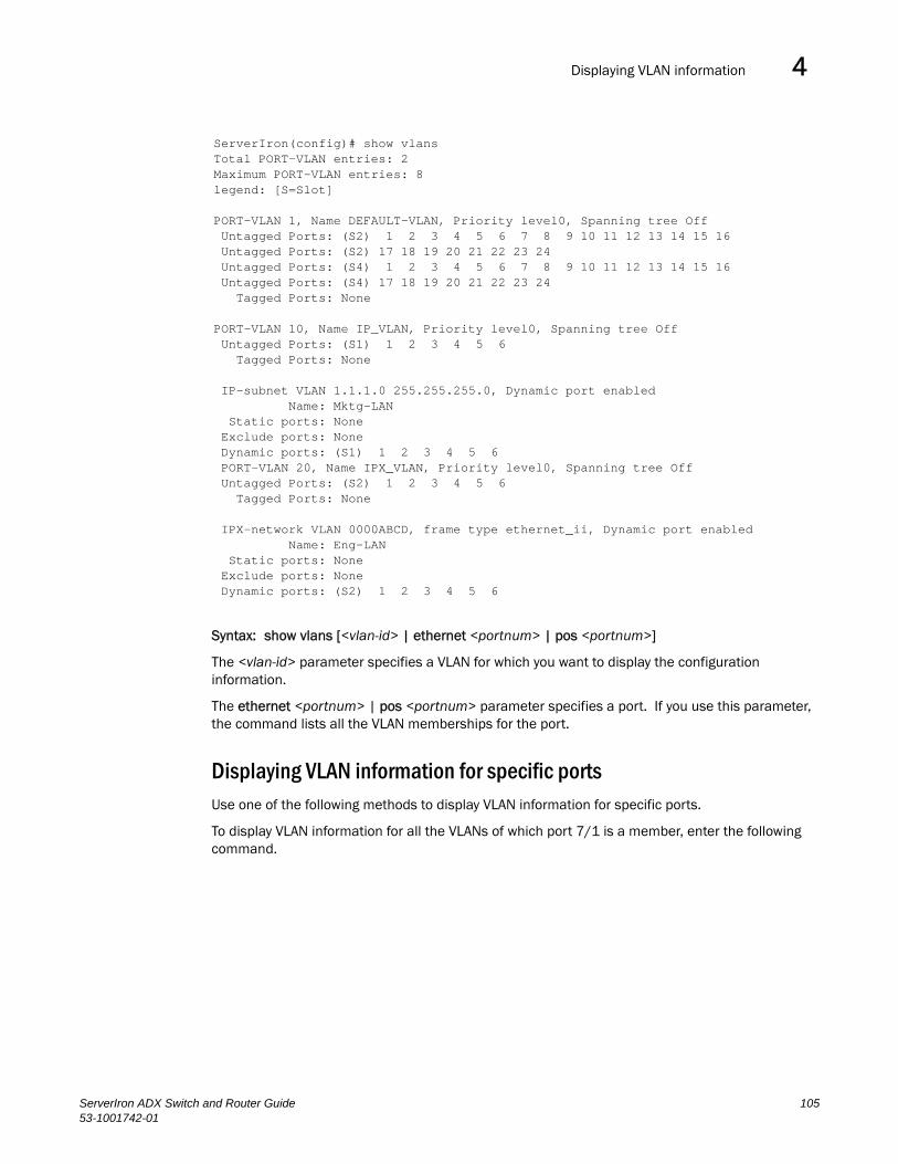
Displaying VLAN information 4DRAFT: BROCADE CONFIDENTIAL
Syntax: show vlans [<vlan-id> | ethernet <portnum> | pos <portnum>]
The <vlan-id> parameter specifies a VLAN for which you want to display the configuration information.
The ethernet <portnum> | pos <portnum> parameter specifies a port. If you use this parameter, the command lists all the VLAN memberships for the port.
Displaying VLAN information for specific portsUse one of the following methods to display VLAN information for specific ports.
To display VLAN information for all the VLANs of which port 7/1 is a member, enter the following command.
ServerIron(config)# show vlansTotal PORT-VLAN entries: 2Maximum PORT-VLAN entries: 8legend: [S=Slot]
PORT-VLAN 1, Name DEFAULT-VLAN, Priority level0, Spanning tree Off Untagged Ports: (S2) 1 2 3 4 5 6 7 8 9 10 11 12 13 14 15 16 Untagged Ports: (S2) 17 18 19 20 21 22 23 24 Untagged Ports: (S4) 1 2 3 4 5 6 7 8 9 10 11 12 13 14 15 16 Untagged Ports: (S4) 17 18 19 20 21 22 23 24 Tagged Ports: None
PORT-VLAN 10, Name IP_VLAN, Priority level0, Spanning tree Off Untagged Ports: (S1) 1 2 3 4 5 6 Tagged Ports: None
IP-subnet VLAN 1.1.1.0 255.255.255.0, Dynamic port enabled Name: Mktg-LAN Static ports: None Exclude ports: None Dynamic ports: (S1) 1 2 3 4 5 6 PORT-VLAN 20, Name IPX_VLAN, Priority level0, Spanning tree Off Untagged Ports: (S2) 1 2 3 4 5 6 Tagged Ports: None
IPX-network VLAN 0000ABCD, frame type ethernet_ii, Dynamic port enabled Name: Eng-LAN Static ports: None Exclude ports: None Dynamic ports: (S2) 1 2 3 4 5 6
ServerIron ADX Switch and Router Guide 10553-1001742-01

Displaying VLAN information4DRAFT: BROCADE CONFIDENTIAL
Syntax: show vlans [<vlan-id> | ethernet <portnum> ]
The <vlan-id> parameter specifies a VLAN for which you want to display the configuration information.
The ethernet <portnum> parameter specifies a port. If you use this parameter, the command lists all the VLAN memberships for the port.
Using show run to display VLAN information.You can use the show running-config command to display information for VLANs and VLAN groups. The show running-config command displays VLANs in the order they were configured on the device. Device running Enterprise software release 08.0.00 and later displays VLANs in numerical order (for example, VLAN 100, VLAN 200, and so on in the show running-config output.
ServerIron(config)# show vlans e 7/1Total PORT-VLAN entries: 3Maximum PORT-VLAN entries: 8
legend: [S=Slot]
PORT-VLAN 100, Name [None], Priority level0, Spanning tree Off Untagged Ports: (S7) 1 2 3 4 Tagged Ports: None
IP-subnet VLAN 207.95.11.0 255.255.255.0, Dynamic port disabled Static ports: (S7) 1 2 Exclude ports: None Dynamic ports: None
106 ServerIron ADX Switch and Router Guide53-1001742-01

ServerIron ADX Switch and Router Guide53-1001742-01
DRAFT: BROCADE CONFIDENTIAL
Chapter
5
Configuring Spanning Tree Protocol (STP) and IronSpanAdvanced STP FeaturesIn this chapter•STP overview . . . . . . . . . . . . . . . . . . . . . . . . . . . . . . . . . . . . . . . . . . . . . . . . . 107
•Configuring standard STP parameters . . . . . . . . . . . . . . . . . . . . . . . . . . . . . 107
•Configuring IronSpan features . . . . . . . . . . . . . . . . . . . . . . . . . . . . . . . . . . . 120
•STP per VLAN group. . . . . . . . . . . . . . . . . . . . . . . . . . . . . . . . . . . . . . . . . . . . 167
STP overviewThe Spanning Tree Protocol (STP) eliminates Layer 2 loops in networks, by selectively blocking some ports and allowing other ports to forward traffic, based on global (bridge) and local (port) parameters you can configure.
This chapter describes how to configure Spanning Tree Protocol (STP) parameters on Brocade Layer 3 Switches.
You can enable or disable STP on a global basis (for the entire device), a port-based VLAN basis (for the individual Layer 2 broadcast domain), or an individual port basis.
Configuration procedures are provided for the standard STP bridge and port parameters as well as Brocade IronSpan parameters.
IronSpan is a set of Layer 2 features that enable you to overcome limitations in the standard 802.1d Spanning Tree Protocol (STP). IronSpan includes the following features:
• Fast Port Span
• Fast Uplink Span
• Rapid Spanning Tree (both 802.1W Draft 3 and full 802.1W are supported)
• Single-instance STP
• STP per VLAN group
These enhancements extend the operation of standard STP. IronSpan enables you to fine tune standard STP and avoid some of its limitations:
• To configure standard STP parameters, refer to “Configuring standard STP parameters”.
Configuring standard STP parametersBrocade Layer 2 Switches and s support standard STP as described in the IEEE 802.1D specification. STP is enabled by default on Layer 2 Switches but disabled by default on Layer 3 Switches.
107

Configuring standard STP parameters5DRAFT: BROCADE CONFIDENTIAL
By default, each port-based VLAN on a Brocade device runs a separate spanning tree (a separate instance of STP). A Brocade device has one port-based VLAN (VLAN 1) by default that contains all the device’s ports. Thus, by default each Brocade device has one spanning tree. However, if you configure additional port-based VLANs on a Brocade device, then each of those VLANs on which STP is enabled and VLAN 1 all run separate spanning trees.
If you configure a port-based VLAN on the device, the VLAN has the same STP state as the default STP state on the device. Thus, on Layer 2 Switches, new VLANs have STP enabled by default. On Layer 3 Switches, new VLANs have STP disabled by default. You can enable or disable STP in each VLAN separately. In addition, you can enable or disable STP on individual ports.
STP parameters and defaultsTable 9 lists the default STP states for Brocade devices.
Table 10 lists the default STP bridge parameters. The bridge parameters affect the entire spanning tree. If you are using MSTP, the parameters affect the VLAN. If you are using SSTP, the parameters affect all VLANs that are members of the single spanning tree.
TABLE 9 Default STP States
Device Type Default STP Type Default STP State Default STP State of New VLANsa
a. When you create a port-based VLAN, the new VLAN’s STP state is the same as the default STP state on the device. The new VLAN does not inherit the STP state of the default VLAN.
Layer 2 Switch MSTPb
b. MSTP stands for “Multiple Spanning Tree Protocol”. In this type of STP, each port-based VLAN, including the default VLAN, has its own spanning tree. References in this documentation to “STP” apply to MSTP. The Single Spanning Tree Protocol (SSTP) in another type of STP. SSTP includes all VLANs on which STP is enabled in a single spanning tree. Refer to “Single Spanning Tree (SSTP)” on page 165.
Enabled Enabled
Layer 3 Switch MSTP Disabled Disabled
ServerIron MSTP Enabled Enabled
TABLE 10 Default STP bridge parameters
Parameter Description Default and valid values
Forward Delay The period of time a bridge will wait (the listen and learn period) before beginning to forward data packets.
15 secondsPossible values: 4 – 30 seconds
Maximum Age The interval a bridge will wait for a hello packet from the root bridge before initiating a topology change.
20 secondsPossible values: 6 – 40 seconds
Hello Time The interval of time between each configuration BPDU sent by the root bridge.
2 secondsPossible values: 1 – 10 seconds
Priority A parameter used to identify the root bridge in a spanning tree (instance of STP). The bridge with the lowest value has the highest priority and is the root.A higher numerical value means a lower priority; thus, the highest priority is 0.
32768Possible values: 0 – 65535
108 ServerIron ADX Switch and Router Guide53-1001742-01

Configuring standard STP parameters 5DRAFT: BROCADE CONFIDENTIAL
NOTEIf you plan to change STP bridge timers, Brocade recommends that you stay within the following ranges, from section 8.10.2 of the IEEE STP specification.
2 * (forward_delay -1) >= max_age
max_age >= 2 * (hello_time +1 )
Table 11 lists the default STP port parameters. The port parameters affect individual ports and are separately configurable on each port.
Notice that the path costs favor 100 Mbps ports.
Enabling or disabling the Spanning Tree Protocol (STP)You can enable or disable STP on the following levels:
• Globally – Affects all ports on the device.
• Port-based VLAN – Affects all ports within the specified port-based VLAN. When you enable or disable STP within a port-based VLAN, the setting overrides the global setting. Thus, you can enable STP for the ports within a port-based VLAN even when STP is globally disabled, or disable the ports within a port-based VLAN when STP is globally enabled.
• Individual port – Affects only the individual port. However, if you change the STP state of the primary port in a trunk group, the change affects all ports in the trunk group.
Enabling or disabling STP globally
Use the following methods to enable or disable STP on a device on which you have not configured port-based VLANs.
NOTEWhen you configure a VLAN, the VLAN inherits the global STP settings. However, once you begin to define a VLAN, you can no longer configure standard STP parameters globally using the CLI. From that point on, you can configure STP only within individual VLANs.
To enable STP for all ports in all VLANs on a Brocade device, enter the following command.
ServerIron(config)# spanning-tree
This command enables a separate spanning tree in each VLAN, including the default VLAN.
TABLE 11 Default STP port parameters
Parameter Description Default and valid values
Priority The preference that STP gives this port relative to other ports for forwarding traffic out of the spanning tree.A higher numerical value means a lower priority; thus, the highest priority is 8.
128Possible values: 8 – 252(configurable in increments of 4)
Path Cost The cost of using the port to reach the root bridge. When selecting among multiple links to the root bridge, STP chooses the link with the lowest path cost and blocks the other paths. Each port type has its own default STP path cost.
10 Mbps – 100100 Mbps – 19Gigabit – 410 Gigabit – 2Possible values are 0 – 65535
ServerIron ADX Switch and Router Guide 10953-1001742-01
Configuring standard STP parameters5DRAFT: BROCADE CONFIDENTIAL
Syntax: [no] spanning-tree
Enabling or disabling STP in a port-based VLAN
Use the following procedure to disable or enable STP on a device on which you have configured a port-based VLAN. Changing the STP state in a VLAN affects only that VLAN.
To enable STP for all ports in a port-based VLAN, enter commands such as the following.
ServerIron(config)# vlan 10ServerIron(config-vlan-10)# spanning-tree
Syntax: [no] spanning-tree
Enabling or disabling STP on an individual port
Use the following procedure to disable or enable STP on an individual port.
NOTEIf you change the STP state of the primary port in a trunk group, the change affects all ports in the trunk group.
To enable STP on an individual port, enter commands such as the following.
ServerIron(config)# interface 1/1ServerIron(config-if-1/1)# spanning-tree
Syntax: [no] spanning-tree
Changing STP bridge and port parametersTable 10 on page 108 and Table 11 on page 109 list the default STP parameters. If you need to change the default value for an STP parameter, use the following procedures.
Changing STP bridge parameters
To change STP bridge parameters, use either of the following methods.
NOTEIf you plan to change STP bridge timers, Brocade recommends that you stay within the following ranges, from section 8.10.2 of the IEEE STP specification.
2 * (forward_delay -1) >= max_age
max_age >= 2 * (hello_time +1 )
To change a Brocade device’s STP bridge priority to the highest value to make the device the root bridge, enter the following command.
ServerIron(config)# spanning-tree priority 0
The command in this example changes the priority on a device on which you have not configured port-based VLANs. The change applies to the default VLAN. If you have configured a port-based VLAN on the device, you can configure the parameters only at the configuration level for individual VLANs. Enter commands such as the following.
110 ServerIron ADX Switch and Router Guide53-1001742-01
Configuring standard STP parameters 5DRAFT: BROCADE CONFIDENTIAL
ServerIron(config)# vlan 20ServerIron(config-vlan-20)# spanning-tree priority 0
To make this change in the default VLAN, enter the following commands.
ServerIron(config)# vlan 1ServerIron(config-vlan-1)# spanning-tree priority 0
Syntax: [no] spanning-tree [forward-delay <value>] | [hello-time <value>] | [maximum-age <value>] | [priority <value>]
The forward-delay <value> parameter specifies the forward delay and can be a value from 4 – 30 seconds. The default is 15 seconds.
NOTEYou can configure a Brocade device for faster convergence (including a shorter forward delay) using Fast Span or Fast Uplink Span. Refer to “Configuring IronSpan features” on page 120.
The hello-time <value> parameter specifies the hello time and can be a value from 1 – 10 seconds. The default is 2 seconds.
NOTEThis parameter applies only when this device or VLAN is the root bridge for its spanning tree.
The maximum-age <value> parameter specifies the amount of time the device waits for receipt of a hello packet before initiating a topology change. You can specify from 6 – 40 seconds. The default is 20 seconds.
The priority <value> parameter specifies the priority and can be a value from 0 – 65535. A higher numerical value means a lower priority. Thus, the highest priority is 0. The default is 32768.
You can specify some or all of these parameters on the same command line. If you specify more than one parameter, you must specify them in the order shown above, from left to right.
Changing STP port parameters
To change STP port parameters, use either of the following methods.
To change the path and priority costs for a port, enter commands such as the following.
ServerIron(config)# vlan 10ServerIron(config-vlan-10)# spanning-tree ethernet 1/5 path-cost 15 priority 64
Syntax: spanning-tree ethernet path-cost <value> | priority <value> | disable | enable
The ethernet parameter specifies the interface.
The path-cost <value> parameter specifies the port’s cost as a path to the spanning tree’s root bridge. STP prefers the path with the lowest cost. You can specify a value from 0 – 65535.
The default depends on the port type:
• 10 Mbps – 100
• 100 Mbps – 19
• Gigabit – 4
• 10 Gigabit – 2
ServerIron ADX Switch and Router Guide 11153-1001742-01
Configuring standard STP parameters5DRAFT: BROCADE CONFIDENTIAL
The priority <value> parameter specifies the preference that STP gives this port relative to other ports for forwarding traffic out of the spanning tree. You can specify a value from 8 – 252, in increments of 4. If you enter a value that is not divisible by four the software rounds to the nearest value that is. The default is 128. A higher numerical value means a lower priority; thus, the highest priority is 8.
NOTEThe range in software releases earlier than 07.5.01 is 0 – 255. If you are upgrading a device that has a configuration saved under an earlier software release, and the configuration contains a value from 0 – 7 for a port’s STP priority, the software changes the priority to the default when you save the configuration while running the new release.
The disable | enable parameter disables or re-enables STP on the port. The STP state change affects only this VLAN. The port’s STP state in other VLANs is not changed.
Displaying STP informationYou can display the following STP information:
• All the global and interface STP settings
• CPU utilization statistics
• Detailed STP information for each interface
• STP state information for a port-based VLAN
• STP state information for an individual interface
Displaying STP information for an entire device
To display STP information for an entire device, enter the following command at any level of the CLI.
112 ServerIron ADX Switch and Router Guide53-1001742-01

Configuring standard STP parameters 5DRAFT: BROCADE CONFIDENTIAL
Syntax: show span [vlan <vlan-id>] | [<num>] | [detail [vlan <vlan-id> [atm <portnum> | ethernet <portnum>] | <num>]]
The vlan <vlan-id> parameter displays STP information for the specified port-based VLAN.
The <num> parameter displays only the entries after the number you specify. For example, on a device with three port-based VLANs, if you enter 1, then information for the second and third VLANs is displayed, but information for the first VLAN is not displayed. Information is displayed according to VLAN number, in ascending order. The entry number is not the same as the VLAN number. For example, if you have port-based VLANs 1, 10, and 2024, then the command output has three STP entries. To display information for VLANs 10 and 2024 only, enter show span 1.
The detail parameter and its additional optional parameters display detailed information for individual ports. Refer to “Displaying detailed STP information for each interface” on page 117.
The show span command shows the following information.
TABLE 12 CLI display of STP information
This field... Displays...
Global STP Parameters
VLAN ID The port-based VLAN that contains this spanning tree (instance of STP). VLAN 1 is the default VLAN. If you have not configured port-based VLANs on this device, all STP information is for VLAN 1.
Root ID The ID assigned by STP to the root bridge for this spanning tree.
Root Cost The cumulative cost from this bridge to the root bridge. If this device is the root bridge, then the root cost is 0.
Root Port The port on this device that connects to the root bridge. If this device is the root bridge, then the value is “Root” instead of a port number.
ServerIron# show span
VLAN 1 BPDU cam_index is 3 and the Master DMA Are(HEX)STP instance owned by VLAN 1
Global STP (IEEE 802.1D) Parameters:
VLAN Root Root Root Prio Max He- Ho- Fwd Last Chg Bridge ID ID Cost Port rity Age llo ld dly Chang cnt Address Hex sec sec sec sec sec 1 800000e0804d4a00 0 Root 8000 20 2 1 15 689 1 00e0804d4a00 Port STP Parameters:
Port Prio Path State Fwd Design Designated DesignatedNum rity Cost Trans Cost Root Bridge Hex1 80 19 FORWARDING 1 0 800000e0804d4a00 800000e0804d4a002 80 0 DISABLED 0 0 0000000000000000 00000000000000003 80 0 DISABLED 0 0 0000000000000000 00000000000000004 80 0 DISABLED 0 0 0000000000000000 00000000000000005 80 19 FORWARDING 1 0 800000e0804d4a00 800000e0804d4a006 80 19 BLOCKING 0 0 800000e0804d4a00 800000e0804d4a007 80 0 DISABLED 0 0 0000000000000000 0000000000000000 <lines for remaining ports excluded for brevity>
ServerIron ADX Switch and Router Guide 11353-1001742-01

Configuring standard STP parameters5DRAFT: BROCADE CONFIDENTIAL
Priority Hex This device or VLAN’s STP priority. The value is shown in hexadecimal format.
NOTE: If you configure this value, specify it in decimal format. Refer to “Changing STP bridge parameters” on page 110.
Max age sec The number of seconds this device or VLAN waits for a hello message from the root bridge before deciding the root has become unavailable and performing a reconvergence.
Hello sec The interval between each configuration BPDU sent by the root bridge.
Hold sec The minimum number of seconds that must elapse between transmissions of consecutive Configuration BPDUs on a port.
Fwd dly sec The number of seconds this device or VLAN waits following a topology change and consequent reconvergence.
Last Chang sec The number of seconds since the last time a topology change occurred.
Chg cnt The number of times the topology has changed since this device was reloaded.
Bridge Address The STP address of this device or VLAN.
NOTE: If this address is the same as the Root ID, then this device or VLAN is the root bridge for its spanning tree.
Port STP Parameters
Port Num The port number.
Priority Hex The port’s STP priority, in hexadecimal format.
NOTE: If you configure this value, specify it in decimal format. Refer to “Changing STP port parameters” on page 111.
Path Cost The port’s STP path cost.
State The port’s STP state. The state can be one of the following:• BLOCKING – STP has blocked Layer 2 traffic on this port to prevent a loop.
The device or VLAN can reach the root bridge using another port, whose state is FORWARDING. When a port is in this state, the port does not transmit or receive user frames, but the port does continue to receive STP BPDUs.
• DISABLED – The port is not participating in STP. This can occur when the port is disconnected or STP is disabled on the port.
• FORWARDING – STP is allowing the port to send and receive frames.• LISTENING – STP is responding to a topology change and this port is
listening for a BPDU from neighboring bridge(s) in order to determine the new topology. No user frames are transmitted or received during this state.
• LEARNING – The port has passed through the LISTENING state and will change to the BLOCKING or FORWARDING state, depending on the results of STP’s reconvergence. The port does not transmit or receive user frames during this state. However, the device can learn the MAC addresses of frames that the port receives during this state and make corresponding entries in the MAC table.
Fwd Trans The number of times STP has changed the state of this port between BLOCKING and FORWARDING.
Design Cost The cost to the root bridge as advertised by the designated bridge that is connected to this port. If the designated bridge is the root bridge itself, then the cost is 0. The identity of the designated bridge is shown in the Design Bridge field.
TABLE 12 CLI display of STP information (Continued)
This field... Displays...
114 ServerIron ADX Switch and Router Guide53-1001742-01

Configuring standard STP parameters 5DRAFT: BROCADE CONFIDENTIAL
Displaying CPU utilization statistics
You can display CPU utilization statistics for STP and the IP protocols.
To display CPU utilization statistics for STP for the previous one-second, one-minute, five-minute, and fifteen-minute intervals, enter the following command at any level of the CLI.
If the software has been running less than 15 minutes (the maximum interval for utilization statistics), the command indicates how long the software has been running. Here is an example:
To display utilization statistics for a specific number of seconds, enter a command such as the following.
Design Root The root bridge as recognized on this port. The value is the same as the root bridge ID listed in the Root ID field.
Design Bridge The designated bridge to which this port is connected. The designated bridge is the device that connects the network segment on the port to the root bridge.
TABLE 12 CLI display of STP information (Continued)
This field... Displays...
ServerIron# show process cpuProcess Name 5Sec(%) 1Min(%) 5Min(%) 15Min(%) Runtime(ms)ARP 0.01 0.03 0.09 0.22 9BGP 0.04 0.06 0.08 0.14 13GVRP 0.00 0.00 0.00 0.00 0ICMP 0.00 0.00 0.00 0.00 0IP 0.00 0.00 0.00 0.00 0OSPF 0.00 0.00 0.00 0.00 0RIP 0.00 0.00 0.00 0.00 0STP 0.00 0.03 0.04 0.07 4VRRP 0.00 0.00 0.00 0.00 0
ServerIron# show process cpuThe system has only been up for 6 seconds.Process Name 5Sec(%) 1Min(%) 5Min(%) 15Min(%) Runtime(ms)ARP 0.01 0.00 0.00 0.00 0BGP 0.00 0.00 0.00 0.00 0GVRP 0.00 0.00 0.00 0.00 0ICMP 0.01 0.00 0.00 0.00 1IP 0.00 0.00 0.00 0.00 0OSPF 0.00 0.00 0.00 0.00 0RIP 0.00 0.00 0.00 0.00 0STP 0.00 0.00 0.00 0.00 0VRRP 0.00 0.00 0.00 0.00 0
ServerIron ADX Switch and Router Guide 11553-1001742-01

Configuring standard STP parameters5DRAFT: BROCADE CONFIDENTIAL
When you specify how many seconds’ worth of statistics you want to display, the software selects the sample that most closely matches the number of seconds you specified. In this example, statistics are requested for the previous two seconds. The closest sample available is actually for the previous 1 second plus 80 milliseconds.
Syntax: show process cpu [<num>]
The <num> parameter specifies the number of seconds and can be from 1 – 900. If you use this parameter, the command lists the usage statistics only for the specified number of seconds. If you do not use this parameter, the command lists the usage statistics for the previous one-second, one-minute, five-minute, and fifteen-minute intervals.
Displaying the STP state of a port-based VLAN
When you display information for a port-based VLAN, that information includes the STP state of the VLAN. To display information for a port-based VLAN, enter a command such as the following at any level of the CLI. The STP state is shown in bold type in this example.
Syntax: show vlans [<vlan-id> | ethernet <portnum>]
The <vlan-id> parameter specifies a VLAN for which you want to display the configuration information.
ServerIron# show process cpu 2Statistics for last 1 sec and 80 msProcess Name Sec(%) Time(ms)ARP 0.00 0BGP 0.00 0GVRP 0.00 0ICMP 0.01 1IP 0.00 0OSPF 0.00 0RIP 0.00 0STP 0.01 0VRRP 0.00 0
ServerIron(config)# show vlans
Total PORT-VLAN entries: 2Maximum PORT-VLAN entries: 16
legend: [S=Slot]
PORT-VLAN 1, Name DEFAULT-VLAN, Priority level0, Spanning tree On Untagged Ports: (S3) 1 2 3 4 5 6 7 8 9 10 11 12 13 14 15 16 Untagged Ports: (S3) 17 18 19 20 21 22 23 24 Untagged Ports: (S4) 2 3 4 5 6 7 8 9 10 11 12 13 14 15 16 17 Untagged Ports: (S4) 18 19 20 21 22 23 24 Tagged Ports: None Uplink Ports: None
PORT-VLAN 2, Name greenwell, Priority level0, Spanning tree Off Untagged Ports: (S1) 1 2 3 4 5 6 7 8 Untagged Ports: (S4) 1 Tagged Ports: None Uplink Ports: None
116 ServerIron ADX Switch and Router Guide53-1001742-01

Configuring standard STP parameters 5DRAFT: BROCADE CONFIDENTIAL
The ethernet <portnum> parameter specifies a port. If you use this parameter, the command lists all the VLAN memberships for the port.
Displaying detailed STP information for each interface
To display the detailed STP information, enter the following command at any level of the CLI.
If a port is disabled, the only information shown by this command is “DISABLED”. If a port is enabled, this display shows the following information.
Syntax: show span detail [vlan <vlan-id> ethernet <portnum> | <num>]
The vlan <vlan-id> parameter specifies a VLAN.
The ethernet <portnum> parameter specifies an individual port within the VLAN (if specified).
The <num> parameter specifies the number of VLANs you want the CLI to skip before displaying detailed STP information. For example, if the device has six VLANs configured (VLAN IDs 1, 2, 3, 99, 128, and 256) and you enter the command show span detail 4, detailed STP information is displayed for VLANs 128 and 256 only.
NOTEIf the configuration includes VLAN groups, the show span detail command displays the master VLANs of each group but not the member VLANs within the groups. However, the command does indicate that the VLAN is a master VLAN. The show span detail vlan <vlan-id> command displays the information for the VLAN even if it is a member VLAN. To list all the member VLANs within a VLAN group, enter the show vlan-group [<group-id>] command.
The show span detail command shows the following information.
ServerIron# show span detail======================================================================VLAN 1 - MULTIPLE SPANNING TREE (MSTP) ACTIVE======================================================================Bridge identifier - 0x800000e0804d4a00Active global timers - Hello: 0
Port 1/1 is FORWARDING Port - Path cost: 19, Priority: 128, Root: 0x800000e052a9bb00 Designated - Bridge: 0x800000e052a9bb00, Interface: 1, Path cost: 0 Active Timers - None BPDUs - Sent: 11, Received: 0Port 1/2 is DISABLEDPort 1/3 is DISABLEDPort 1/4 is DISABLED<lines for remaining ports excluded for brevity>
ServerIron ADX Switch and Router Guide 11753-1001742-01

Configuring standard STP parameters5DRAFT: BROCADE CONFIDENTIAL
TABLE 13 CLI display of detailed STP information for ports
This field... Displays...
Active Spanning Tree protocol The VLAN that contains the listed ports and the active Spanning Tree protocol.The STP type can be one of the following:• MULTIPLE SPANNNG TREE (MSTP)• GLOBAL SINGLE SPANNING TREE (SSTP)
NOTE: If STP is disabled on a VLAN, the command displays the following message instead: “Spanning-tree of port-vlan <vlan-id> is disabled.”
Bridge identifier The STP identity of this device.
Active global timers The global STP timers that are currently active, and their current values. The following timers can be listed:• Hello – The interval between Hello packets. This timer applies only to the
root bridge.• Topology Change (TC) – The amount of time during which the topology
change flag in Hello packets will be marked, indicating a topology change. This timer applies only to the root bridge.
• Topology Change Notification (TCN) – The interval between Topology Change Notification packets sent by a non-root bridge toward the root bridge. This timer applies only to non-root bridges.
Port number and STP state The internal port number and the port’s STP state. The internal port number is one of the following:• The port’s interface number, if the port is the designated port for the LAN.• The interface number of the designated port from the received BPDU, if
the interface is not the designated port for the LAN.The state can be one of the following:• BLOCKING – STP has blocked Layer 2 traffic on this port to prevent a loop.
The device or VLAN can reach the root bridge using another port, whose state is FORWARDING. When a port is in this state, the port does not transmit or receive user frames, but the port does continue to receive STP BPDUs.
• DISABLED – The port is not participating in STP. This can occur when the port is disconnected or STP is administratively disabled on the port.
• FORWARDING – STP is allowing the port to send and receive frames.• LISTENING – STP is responding to a topology change and this port is
listening for a BPDU from neighboring bridge(s) in order to determine the new topology. No user frames are transmitted or received during this state.
• LEARNING – The port has passed through the LISTENING state and will change to the BLOCKING or FORWARDING state, depending on the results of STP’s reconvergence. The port does not transmit or receive user frames during this state. However, the device can learn the MAC addresses of frames that the port receives during this state and make corresponding entries in the MAC table.
NOTE: If the state is DISABLED, no further STP information is displayed for the port.
Port Path cost The port’s STP path cost.
Port Priority This port’s STP priority. The value is shown as a hexadecimal number.
Root The ID assigned by STP to the root bridge for this spanning tree.
Designated Bridge The MAC address of the designated bridge to which this port is connected. The designated bridge is the device that connects the network segment on the port to the root bridge.
118 ServerIron ADX Switch and Router Guide53-1001742-01

Configuring standard STP parameters 5DRAFT: BROCADE CONFIDENTIAL
Displaying detailed STP information for a single port in a specific VLANEnter a command such as the following to display STP information for an individual port in a specific VLAN.
Syntax: show span detail [vlan <vlan-id> [atm <portnum> | ethernet <portnum> | pos <portnum>] | <num>]
Displaying STP state information for an individual interface
To display STP state information for an individual port, you can use the methods in “Displaying STP information for an entire device” on page 112 or “Displaying detailed STP information for each interface”.
To display information for a specific port, enter a command such as the following at any level of the CLI.
Designated Port The port number sent from the designated bridge.
Designated Path Cost The cost to the root bridge as advertised by the designated bridge that is connected to this port. If the bridge is the root bridge itself, then the cost is 0. The identity of the designated bridge is shown in the Designated Bridge field.
Active Timers The current values for the following timers, if active:• Message age – The number of seconds this port has been waiting for a
hello message from the root bridge.• Forward delay – The number of seconds that have passed since the last
topology change and consequent reconvergence.• Hold time – The number of seconds that have elapsed since
transmission of the last Configuration BPDU.
BPDUs Sent and Received The number of BPDUs sent and received on this port since the software was reloaded.
TABLE 13 CLI display of detailed STP information for ports (Continued)
This field... Displays...
ServerIron(config)# show span detail vlan 1 ethernet 7/1Port 7/1 is FORWARDING Port - Path cost: 19, Priority: 128, Root: 0x800000e052a9bb00 Designated - Bridge: 0x800000e052a9bb00, Interface: 7, Path cost: 0 Active Timers - None BPDUs - Sent: 29, Received: 0
ServerIron ADX Switch and Router Guide 11953-1001742-01

Configuring IronSpan features5DRAFT: BROCADE CONFIDENTIAL
The STP information is shown in bold type in this example.
Syntax: show interfaces [ethernet <portnum>] | [loopback <num>] | [slot <slot-num>] | [ve <num>] | [brief]
You also can display the STP states of all ports by entering a command such as the following, which uses the brief parameter.
In this example, only one port, 3/11, is forwarding traffic toward the root bridge.
Configuring IronSpan featuresThis section describes how to configure the following features:
• Fast Port Span – refer to “Fast Port Span”
• Fast Uplink Span – refer to “Fast Uplink Span”
ServerIron(config)# show interface ethernet 3/11
FastEthernet3/11 is up, line protocol is up Hardware is FastEthernet, address is 00e0.52a9.bb49 (bia 00e0.52a9.bb49) Configured speed auto, actual 100Mbit, configured duplex fdx, actual fdx Member of L2 VLAN ID 1, port is untagged, port state is FORWARDING STP configured to ON, priority is level0, flow control enabled mirror disabled, monitor disabled Not member of any active trunks Not member of any configured trunks No port name MTU 1518 bytes, encapsulation ethernet 5 minute input rate: 352 bits/sec, 0 packets/sec, 0.00% utilization 5 minute output rate: 0 bits/sec, 0 packets/sec, 0.00% utilization 1238 packets input, 79232 bytes, 0 no buffer Received 686 broadcasts, 0 runts, 0 giants 0 input errors, 0 CRC, 0 frame, 0 ignored 529 multicast 918 packets output, 63766 bytes, 0 underruns 0 output errors, 0 collisions
ServerIron(config)# show interface brief
Port Link State Dupl Speed Trunk Tag Priori MAC Name1/1 Down None None None None No level0 00e0.52a9.bb001/2 Down None None None None No level0 00e0.52a9.bb011/3 Down None None None None No level0 00e0.52a9.bb021/4 Down None None None None No level0 00e0.52a9.bb031/5 Down None None None None No level0 00e0.52a9.bb041/6 Down None None None None No level0 00e0.52a9.bb051/7 Down None None None None No level0 00e0.52a9.bb061/8 Down None None None None No level0 00e0.52a9.bb07
.
. some rows omitted for brevity
.3/10 Down None None None None No level0 00e0.52a9.bb4a3/11 Up Forward Full 100M None No level0 00e0.52a9.bb49
120 ServerIron ADX Switch and Router Guide53-1001742-01

Configuring IronSpan features 5DRAFT: BROCADE CONFIDENTIAL
• 802.1W Rapid Spanning Tree (RSTP) – refer to “802.1W Rapid Spanning Tree (RSTP)” on page 124
• 802.1W Draft 3 RSTP – refer to “802.1W Draft 3” on page 161
• Single-instance STP – refer to “Single Spanning Tree (SSTP)” on page 165
• STP per VLAN group – refer to “STP per VLAN group” on page 167
Fast Port SpanWhen STP is running on a device, message forwarding is delayed during the spanning tree recalculation period following a topology change. The STP forward delay parameter specifies the period of time a bridge waits before forwarding data packets. The forward delay controls the listening and learning periods of STP reconvergence. You can configure the forward delay to a value from 4 – 30 seconds. The default is 15 seconds. Thus, using the standard forward delay, convergence requires 30 seconds (15 seconds for listening and an additional 15 seconds for learning) when the default value is used.
This slow convergence is undesirable and unnecessary in some circumstances. The Fast Port Span feature allows certain ports to enter the forwarding state in four seconds. Specifically, Fast Port Span allows faster convergence on ports that are attached to end stations and thus do not present the potential to cause Layer 2 forwarding loops. Because the end stations cannot cause forwarding loops, they can safely go through the STP state changes (blocking to listening to learning to forwarding) more quickly than is allowed by the standard STP convergence time. Fast Port Span performs the convergence on these ports in four seconds (two seconds for listening and two seconds for learning).
In addition, Fast Port Span enhances overall network performance in the following ways:
• Fast Port Span reduces the number of STP topology change notifications on the network. When an end station attached to a Fast Span port comes up or down, the Brocade device does not generate a topology change notification for the port. In this situation, the notification is unnecessary since a change in the state of the host does not affect the network’s topology.
• Fast Port Span eliminates unnecessary MAC cache aging that can be caused by topology change notifications. Bridging devices age out the learned MAC addresses in their MAC caches if the addresses are unrefreshed for a given period of time, sometimes called the MAC aging interval. When STP sends a topology change notification, devices that receive the notification use the value of the STP forward delay to quickly age out their MAC caches. For example, if a device’s normal MAC aging interval is 5 minutes, the aging interval changes temporarily to the value of the forward delay (for example, 15 seconds) in response to an STP topology change.
In normal STP, the accelerated cache aging occurs even when a single host goes up or down. Because Fast Port Span does not send a topology change notification when a host on a Fast Port Span port goes up or down, the unnecessary cache aging that can occur in these circumstances under normal STP is eliminated.
Fast Port Span is a system-wide parameter and is enabled by default. Thus, when you boot a device with software release 06.0.00 or later, all the ports that are attached only to end stations run Fast Port Span. For ports that are not eligible for Fast Port Span, such as ports connected to other networking devices, the device automatically uses the normal STP settings. If a port matches any of the following criteria, the port is ineligible for Fast Port Span and uses normal STP instead:
• The port is 802.1q tagged
• The port is a member of a trunk group
ServerIron ADX Switch and Router Guide 12153-1001742-01

Configuring IronSpan features5DRAFT: BROCADE CONFIDENTIAL
• The port has learned more than one active MAC address
• An STP Configuration BPDU has been received on the port, thus indicating the presence of another bridge on the port.
You also can explicitly exclude individual ports from Fast Port Span if needed. For example, if the only uplink ports for a wiring closet switch are Gigabit ports, you can exclude the ports from Fast Port Span.
Disabling and re-enabling Fast Port Span
Fast Port Span is a system-wide parameter and is enabled by default. Thus all ports that are eligible for Fast Port Span use it.
To disable Fast Port Span, enter the following commands.
ServerIron(config)# no fast port-spanServerIron(config)# write memory
Syntax: [no] fast port-span
NOTEThe fast port-span command has additional parameters that let you exclude specific ports. These parameters are shown in the following section.
To re-enable Fast Port Span, enter the following commands.
ServerIron(config)# fast port-spanServerIron(config)# write memory
Excluding specific ports from Fast Port Span
You can exclude individual ports from Fast Port Span while leaving Fast Port Span enabled globally. To exclude a port from Fast Port Span, enter commands such as the following.
ServerIron(config)# fast port-span exclude ethernet 1/1ServerIron(config)# write memory
To exclude a set of ports from Fast Port Span, enter commands such as the following.
ServerIron(config)# fast port-span exclude ethernet 1/1 ethernet 2/1 ethernet 3/2ServerIron(config)# write memory
To exclude a contiguous (unbroken) range of ports from Fast Span, enter commands such as the following.
ServerIron(config)# fast port-span exclude ethernet 1/1 to 1/24ServerIron(config)# write memory
Syntax: [no] fast port-span [exclude ethernet <portnum> [ethernet <portnum>… | to <portnum>]]
To re-enable Fast Port Span on a port, enter a command such as the following.
ServerIron(config)# no fast port-span exclude ethernet 1/1 ServerIron(config)# write memory
This command re-enables Fast Port Span on port 1/1 only and does not re-enable Fast Port Span on other excluded ports. You also can re-enable Fast Port Span on a list or range of ports using the syntax shown above this example.
To re-enable Fast Port Span on all excluded ports, disable and then re-enable Fast Port Span by entering the following commands.
122 ServerIron ADX Switch and Router Guide53-1001742-01

Configuring IronSpan features 5DRAFT: BROCADE CONFIDENTIAL
ServerIron(config)# no fast port-span ServerIron(config)# fast port-spanServerIron(config)# write memory
Disabling and then re-enabling Fast Port Span clears the exclude settings and thus enables Fast Port Span on all eligible ports. To make sure Fast Port Span remains enabled on the ports following a system reset, save the configuration changes to the startup-config file after you re-enable Fast Port Span. Otherwise, when the system resets, those ports will again be excluded from Fast Port Span.
Fast Uplink SpanThe Fast Port Span feature described in the previous section enhances STP performance for end stations. The Fast Uplink feature enhances STP performance for wiring closet switches with redundant uplinks. Using the default value for the standard STP forward delay, convergence following a transition from an active link to a redundant link can take 30 seconds (15 seconds for listening and an additional 15 seconds for learning).
You can use the Fast Uplink feature on a Brocade device deployed as a wiring closet switch to decrease the convergence time for the uplink ports to another device to just four seconds (two seconds for listening and two seconds for learning). The wiring closet switch must be a Brocade device but the device at the other end of the link can be a Brocade device or another vendor’s switch. Configuration of the Fast Uplink Span feature takes place entirely on the Brocade device.
To configure the Fast Uplink Span feature, specify a group of ports that have redundant uplinks on the wiring closet switch (Brocade device) as members of a Fast Uplink Group. If the active link becomes unavailable, the Fast Uplink Span feature transitions the forwarding to one of the other ports in four seconds. You can configure one Fast Uplink Span group on the device. All Fast Uplink Span ports are members of the same Fast Uplink Span group.
NOTETo avoid the potential for temporary bridging loops, we recommend that you use the Fast Uplink feature only for wiring closet switches (switches at the edge of the network cloud). In addition, enable the feature only on a group of ports intended for redundancy, so that at any given time only one of the ports is expected to be in the forwarding state.
NOTEWhen the wiring closet switch (Brocade device) first comes up or when STP is first enabled, the uplink ports still must go through the standard STP state transition without any acceleration. This behavior guards against temporary routing loops as the switch tries to determine the states for all the ports. Fast Uplink Span acceleration applies only when a working uplink becomes unavailable.
Fast Uplink Span rules for trunk groups
If you add a port to a Fast Uplink Span group that is a member of a trunk group, the following rules apply:
• If you add the primary port of a trunk group to the Fast Uplink Span group, all other ports in the trunk group are automatically included in the group. Similarly, if you remove the primary port in a trunk group from the Fast Uplink Span group, the other ports in the trunk group are automatically removed from the Fast Uplink Span group.
• You cannot add a subset of the ports in a trunk group to the Fast Uplink Span group. All ports in a trunk group have the same Fast Uplink Span property, as they do for other port properties.
ServerIron ADX Switch and Router Guide 12353-1001742-01

Configuring IronSpan features5DRAFT: BROCADE CONFIDENTIAL
• If the working trunk group is partially down but not completely down, no switch-over to the backup occurs. This behavior is the same as in the standard STP feature.
• If the working trunk group is completely down, a backup trunk group can go through an accelerated transition only if the following are true:
• The trunk group is included in the fast uplink group.
• All other ports except those in this trunk group are either disabled or blocked. The accelerated transition applies to all ports in this trunk group.
• When the original working trunk group comes back (partially or fully), the transition back to the original topology is accelerated if the conditions listed above are met.
Configuring a Fast Uplink port group
To configure a group of ports for Fast Uplink Span, enter the following commands.
ServerIron(config)# fast uplink-span ethernet 4/1 to 4/4ServerIron(config)# write memory
Syntax: [no] fast uplink-span [ethernet <portnum> [ethernet <portnum>… | to <portnum>]]
This example configures four ports, 4/1 – 4/4, as a Fast Uplink Span group. In this example, all four ports are connected to a wiring closet switch. Only one of the links is expected to be active at any time. The other links are redundant. For example, if the link on port 4/1 is the active link on the wiring closet switch but becomes unavailable, one of the other links takes over. Because the ports are configured in a Fast Uplink Span group, the STP convergence takes about four seconds instead of taking 30 seconds or longer using the standard STP forward delay.
If you add a port that is the primary port of a trunk group, all ports in the trunk group become members of the Fast Uplink Span group.
You can add ports to a Fast Uplink Span group by entering the fast uplink-span command additional times with additional ports. The device can have only one Fast Uplink Span group, so all the ports you identify as Fast Uplink Span ports are members of the same group.
To remove a Fast Uplink Span group or to remove individual ports from a group, use “no” in front of the appropriate fast uplink-span command. For example, to remove ports 4/3 and 4/4 from the Fast Uplink Span group configured above, enter the following commands.
ServerIron(config)# no fast uplink-span ethernet 4/3 to 4/4ServerIron(config)# write memory
If you delete a port that is the primary port of a trunk group, all ports in the trunk group are removed from the Fast Uplink Span group.
802.1W Rapid Spanning Tree (RSTP)Brocade’s earlier implementation of Rapid Spanning Tree Protocol (RSTP), which was 802.1W Draft 3, provided only a subset of the IEEE 802.1W standard; whereas the 802.1W RSTP feature provides the full standard. The implementation of the 802.1W Draft 3 is referred to as RSTP Draft 3.
RSTP Draft3 will continue to be supported on Brocade devices for backward compatibility. However, customers who are currently using RSTP Draft 3 should migrate to 802.1W.
124 ServerIron ADX Switch and Router Guide53-1001742-01

Configuring IronSpan features 5DRAFT: BROCADE CONFIDENTIAL
The 802.1W feature is supported on all s, as well as on the ServerIron ADX. It provides rapid traffic reconvergence for point-to-point links within a few milliseconds (0 – 500 milliseconds), following the failure of a bridge or bridge port. This reconvergence occurs more rapidly than the reconvergence provided by the 802.1D (Spanning Tree Protocol (STP)) or by RSTP Draft 3.
NOTEThis rapid convergence will not occur on ports connected to shared media devices, such as hubs. To take advantage of the rapid convergence provided by 802.1W, make sure to explicitly configure all point-to-point links in a topology.
The convergence provided by the standard 802.1W protocol occurs more rapidly than the convergence provided by previous spanning tree protocols because:
• Classic or legacy 802.1D STP protocol requires a newly selected Root port to go through listening and learning stages before traffic convergence can be achieved. The 802.1D traffic convergence time is calculated using the following formula:
2 x FORWARD_DELAY + BRIDGE_MAX_AGE.
If default values are used in the parameter configuration, convergence can take up to 50 seconds. (In this document STP will be referred to as 802.1D.)
• RSTP Draft 3 works only on bridges that have Alternate ports, which are the precalculated “next best root port”. (Alternate ports provide back up paths to the root bridge.) Although convergence occurs from 0 – 500 milliseconds in RSTP Draft 3, the spanning tree topology reverts to the 802.1D convergence if an Alternate port is not found.
• Convergence in 802.1w bridge is not based on any timer values. Rather, it is based on the explicit handshakes between Designated ports and their connected Root ports to achieve convergence in less than 500 milliseconds.
Bridges and bridge port roles
A bridge in an 802.1W rapid spanning tree topology is assigned as the root bridge if it has the highest priority (lowest bridge identifier) in the topology. Other bridges are referred to as non-root bridges.
Unique roles are assigned to ports on the root and non-root bridges. Role assignments are based on the following information contained in the Rapid Spanning Tree Bridge Packet Data Unit (RST BPDU):
• Root bridge ID
• Path cost value
• Transmitting bridge ID
• Designated port ID
802.1W algorithm uses this information to determine if the RST BPDU received by a port is superior to the RST BPDU that the port transmits. The two values are compared in the order as given above, starting with the Root bridge ID. The RST BPDU with a lower value is considered superior. The superiority and inferiority of the RST BPDU is used to assign a role to a port.
If the value of the received RST BPDU is the same as that of the transmitted RST BPDU, then the port ID in the RST BPDUs are compared. The RST BPDU with the lower port ID is superior. Port roles are then calculated appropriately.
The port’s role is included in the BPDU that it transmits. The BPDU transmitted by an 802.1W port is referred to as an RST BPDU, while it is operating in 802.1W mode.
ServerIron ADX Switch and Router Guide 12553-1001742-01

Configuring IronSpan features5DRAFT: BROCADE CONFIDENTIAL
Ports can have one of the following roles:
• Root – Provides the lowest cost path to the root bridge from a specific bridge
• Designated – Provides the lowest cost path to the root bridge from a LAN to which it is connected
• Alternate – Provides an alternate path to the root bridge when the root port goes down
• Backup – Provides a backup to the LAN when the Designated port goes down
• Disabled – Has no role in the topology
Assignment of port rolesAt system start-up, all 802.1W-enabled bridge ports assume a Designated role. Once start-up is complete, 802.1W algorithm calculates the superiority or inferiority of the RST BPDU that is received and transmitted on a port.
On a root bridge, each port is assigned a Designated port role, except for ports on the same bridge that are physically connected together. In these type of ports, the port that receives the superior RST BPDU becomes the Backup port, while the other port becomes the Designated port.
On non-root bridges, ports are assigned as follows:
• The port that receives the RST BPDU with the lowest path cost from the root bridge becomes the Root port.
• If two ports on the same bridge are physically connected, the port that receives the superior RST BPDU becomes the Backup port, while the other port becomes the Designated port.
• If a non-root bridge already has a Root port, then the port that receives an RST BPDU that is superior to those it can transmit becomes the Alternate port.
• If the RST BPDU that a port receives is inferior to the RST BPDUs it transmits, then the port becomes a Designated port.
• If the port is down or if 802.1W is disabled on the port, that port is given the role of Disabled port. Disabled ports have no role in the topology. However, if 802.1W is enabled on a port with a link down and the link of that port comes up, then that port assumes one of the following port roles: Root, Designated, Alternate, or Backup.
The following example (Figure 24) explains role assignments in a simple RSTP topology.
NOTEAll examples in this document assume that all ports in the illustrated topologies are point-to-point links and are homogeneous (they have the same path cost value) unless otherwise specified.
The topology in Figure 24 contains four bridges. Switch 1 is the root bridge since it has the lowest bridge priority. Switch 2 through Switch 4 are non-root bridges.
126 ServerIron ADX Switch and Router Guide53-1001742-01
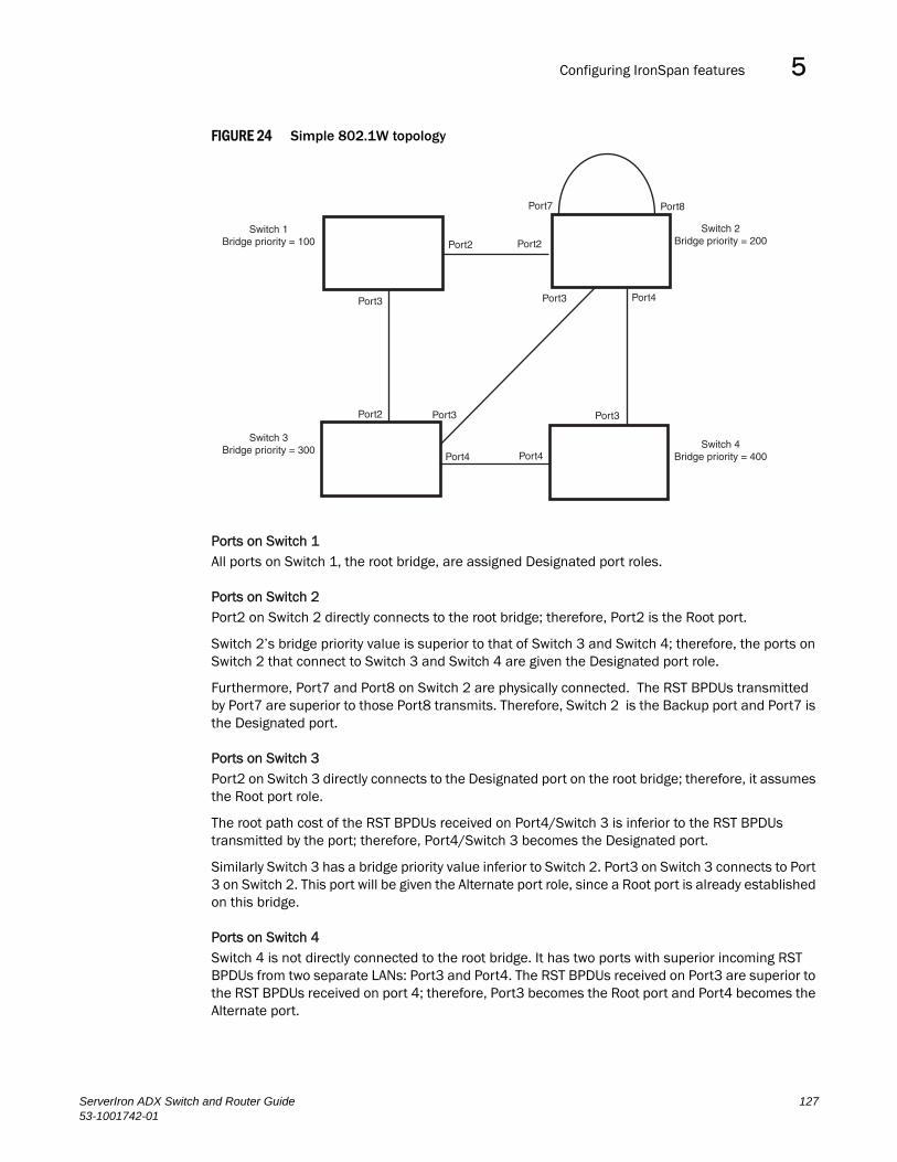
Configuring IronSpan features 5DRAFT: BROCADE CONFIDENTIAL
FIGURE 24 Simple 802.1W topology
Ports on Switch 1All ports on Switch 1, the root bridge, are assigned Designated port roles.
Ports on Switch 2Port2 on Switch 2 directly connects to the root bridge; therefore, Port2 is the Root port.
Switch 2’s bridge priority value is superior to that of Switch 3 and Switch 4; therefore, the ports on Switch 2 that connect to Switch 3 and Switch 4 are given the Designated port role.
Furthermore, Port7 and Port8 on Switch 2 are physically connected. The RST BPDUs transmitted by Port7 are superior to those Port8 transmits. Therefore, Switch 2 is the Backup port and Port7 is the Designated port.
Ports on Switch 3Port2 on Switch 3 directly connects to the Designated port on the root bridge; therefore, it assumes the Root port role.
The root path cost of the RST BPDUs received on Port4/Switch 3 is inferior to the RST BPDUs transmitted by the port; therefore, Port4/Switch 3 becomes the Designated port.
Similarly Switch 3 has a bridge priority value inferior to Switch 2. Port3 on Switch 3 connects to Port 3 on Switch 2. This port will be given the Alternate port role, since a Root port is already established on this bridge.
Ports on Switch 4Switch 4 is not directly connected to the root bridge. It has two ports with superior incoming RST BPDUs from two separate LANs: Port3 and Port4. The RST BPDUs received on Port3 are superior to the RST BPDUs received on port 4; therefore, Port3 becomes the Root port and Port4 becomes the Alternate port.
Switch 1Bridge priority = 100
Switch 2Bridge priority = 200
Switch 3Bridge priority = 300 Switch 4
Bridge priority = 400
Port2 Port2
Port2
Port3
Port3 Port3
Port3
Port4 Port4
Port4
Port7 Port8
ServerIron ADX Switch and Router Guide 12753-1001742-01

Configuring IronSpan features5DRAFT: BROCADE CONFIDENTIAL
Edge ports and edge port roles
Brocade’s implementation of 802.1W allows ports that are configured as Edge ports to be present in an 802.1W topology. (Figure 25). Edge ports are ports of a bridge that connect to workstations or computers. Edge ports do not register any incoming BPDU activities.
Edge ports assume Designated port roles. Port flapping does not cause any topology change events on Edge ports since 802.1W does not consider Edge ports in the spanning tree calculations.
FIGURE 25 Topology with edge ports
However, if any incoming RST BPDU is received from a previously configured Edge port, 802.1W automatically makes the port as a non-edge port. This is extremely important to ensure a loop free Layer 2 operation since a non-edge port is part of the active RSTP topology.
The 802.1W protocol can auto-detect an Edge port and a non-edge port. An administrator can also configure a port to be an Edge port using the CLI. It is recommended that Edge ports are configured explicitly to take advantage of the Edge port feature, instead of allowing the protocol to auto-detect them.
Point-to-point ports
To take advantage of the 802.1W features, ports on an 802.1W topology should be explicitly configured as point-to-point links using the CLI. Shared media should not be configured as point-to-point links.
Switch 1Bridge priority = 600
Switch 2Bridge priority = 1000
Switch 3Bridge priority = 2000
Port2 Port2
Port3 Port3
Port3Port2
Port5Edge Port
Port5Edge Port
128 ServerIron ADX Switch and Router Guide53-1001742-01

Configuring IronSpan features 5DRAFT: BROCADE CONFIDENTIAL
NOTEConfiguring shared media or non-point-to-point links as point-to-point links could lead to Layer 2 loops.
The topology in Figure 26 is an example of shared media that should not be configured as point-to-point links. In Figure 26, a port on a bridge communicates or is connected to at least two ports.
FIGURE 26 Example of shared media
Bridge port states
Ports roles can have one of the following states:
• Forwarding – 802.1W is allowing the port to send and receive all packets.
• Discarding – 802.1W has blocked data traffic on this port to prevent a loop. The device or VLAN can reach the root bridge using another port, whose state is forwarding. When a port is in this state, the port does not transmit or receive data frames, but the port does continue to receive RST BPDUs. This state corresponds to the listening and blocking states of 802.1D.
• Learning – 802.1W is allowing MAC entries to be added to the filtering database but does not permit forwarding of data frames. The device can learn the MAC addresses of frames that the port receives during this state and make corresponding entries in the MAC table.
• Disabled – The port is not participating in 802.1W. This can occur when the port is disconnected or 802.1W is administratively disabled on the port.
A port on a non-root bridge with the role of Root port is always in a forwarding state. If another port on that bridge assumes the Root port role, then the old Root port moves into a discarding state as it assumes another port role.
A port on a non-root bridge with a Designated role starts in the discarding state. When that port becomes elected to the Root port role, 802.1W quickly places it into a forwarding state. However, if the Designated port is an Edge port, then the port starts and stays in a forwarding state and it cannot be elected as a Root port.
A port with an Alternate or Backup role is always in a discarding state. If the port’s role changes to Designated, then the port changes into a forwarding state.
If a port on one bridge has a Designated role and that port is connected to a port on another bridge that has an Alternate or Backup role, the port with a Designated role cannot be given a Root port role until two instances of the forward delay timer expires on that port.
ServerIron ADX Switch and Router Guide 12953-1001742-01

Configuring IronSpan features5DRAFT: BROCADE CONFIDENTIAL
Edge port and non-edge port states
As soon as a port is configured as an Edge port using the CLI, it goes into a forwarding state instantly (in less than 100 msec):
When the link to a port comes up and 802.1W detects that the port is an Edge port, that port instantly goes into a forwarding state.
If 802.1W detects that port as a non-edge port, the port goes into a forwarding state within four seconds of link up or after two hello timer expires on the port.
Changes to port roles and states
To achieve convergence in a topology, a port’s role and state changes as it receives and transmits new RST BPDUs. Changes in a port’s role and state constitute a topology change. Besides the superiority and inferiority of the RST BPDU, bridge-wide and per-port state machines are used to determine a port’s role as well as a port’s state. Port state machines also determine when port role and state changes occur.
State machinesThe bridge uses the Port Role Selection state machine to determine if port role changes are required on the bridge. This state machine performs a computation when one of the following events occur:
• New information is received on any port on the bridge
• The timer expires for the current information on a port on the bridge
Each port uses the following state machines:
• Port Information – This state machine keeps track of spanning-tree information currently used by the port. It records the origin of the information and ages out any information that was derived from an incoming BPDU.
• Port Role Transition – This state machine keeps track of the current port role and transitions the port to the appropriate role when required. It moves the Root port and the Designated port into forwarding states and moves the Alternate and Backup ports into discarding states.
• Port Transmit – This state machine is responsible for BPDU transmission. It checks to ensure only the maximum number of BPDUs per hello interval are sent every second. Based on what mode it is operating in, it sends out either legacy BPDUs or RST BPDUs. In this document legacy BPDUs are also referred to as STP BPDUs.
• Port Protocol Migration – This state machine deals with compatibility with 802.1D bridges. When a legacy BPDU is detected on a port, this state machine configures the port to transmit and receive legacy BPDUs and operate in the legacy mode.
• Topology Change – This state machine detects, generates, and propagates topology change notifications. It acknowledges Topology Change Notice (TCN) messages when operating in 802.1D mode. It also flushes the MAC table when a topology change event takes place.
• Port State Transition – This state machine transitions the port to a discarding, learning, or forwarding state and performs any necessary processing associated with the state changes.
• Port Timers – This state machine is responsible for triggering any of the state machines described above, based on expiration of specific port timers.
In contrast to the 802.1D standard, the 802.1W standard does not have any bridge specific timers. All timers in the CLI are applied on a per-port basis, even though they are configured under bridge parameters.
130 ServerIron ADX Switch and Router Guide53-1001742-01
Configuring IronSpan features 5DRAFT: BROCADE CONFIDENTIAL
802.1W state machines attempt to quickly place the ports into either a forwarding or discarding state. Root ports are quickly placed in forwarding state when both of the following events occur:
• It is assigned to be the Root port.
• It receives an RST BPDU with a proposal flag from a Designated port. The proposal flag is sent by ports with a Designated role when they are ready to move into a forwarding state.
When a the role of Root port is given to another port, the old Root port is instructed to reroot. The old Root port goes into a discarding state and negotiates with its peer port for a new role and a new state. A peer port is the port on the other bridge to which the port is connected. For example, in Figure 27, Port1 of Switch 200 is the peer port of Port2 of Switch 100.
A port with a Designated role is quickly placed into a forwarding state if one of the following occurs:
• The Designated port receives an RST BPDU that contains an agreement flag from a Root port
• The Designated port is an Edge port
However, a Designated port that is attached to an Alternate port or a Backup port must wait until the forward delay timer expires twice on that port while it is still in a Designated role, before it can proceed to the forwarding state.
Backup ports are quickly placed into discarding states.
Alternate ports are quickly placed into discarding states.
A port operating in 802.1W mode may enter a learning state to allow MAC entries to be added to the filtering database; however, this state is transient and lasts only a few milliseconds, if the port is operating in 802.1W mode and if the port meets the conditions for rapid transition.
Handshake mechanisms To rapidly transition a Designated or Root port into a forwarding state, the Port Role Transition state machine uses handshake mechanisms to ensure loop free operations. It uses one type of handshake if no Root port has been assigned on a bridge, and another type if a Root port has already been assigned.
Handshake when no root port is electedIf a Root port has not been assigned on a bridge, 802.1W uses the Proposing -> Proposed -> Sync -> Synced -> Agreed handshake:
• Proposing – The Designated port on the root bridge sends an RST BPDU packet to its peer port that contains a proposal flag. The proposal flag is a signal that indicates that the Designated port is ready to put itself in a forwarding state (Figure 27). The Designated port continues to send this flag in its RST BPDU until it is placed in a forwarding state (Figure 30) or is forced to operate in 802.1D mode. (Refer to “Compatibility of 802.1W with 802.1D” on page 152)
• Proposed – When a port receives an RST BPDU with a proposal flag from the Designated port on its point-to-point link, it asserts the Proposed signal and one of the following occurs (Figure 27):
• If the RST BPDU that the port receives is superior to what it can transmit, the port assumes the role of a Root port. (Refer to the section on “Bridges and bridge port roles” on page 125.)
• If the RST BPDU that the port receives is inferior to what it can transmit, then the port is given the role of Designated port.
NOTEProposed will never be asserted if the port is connected on a shared media link.
ServerIron ADX Switch and Router Guide 13153-1001742-01

Configuring IronSpan features5DRAFT: BROCADE CONFIDENTIAL
In Figure 27, Port3/Switch 200 is elected as the Root port.
FIGURE 27 Proposing and proposed stage
• Sync – Once the Root port is elected, it sets a sync signal on all the ports on the bridge. The signal tells the ports to synchronize their roles and states (Figure 28). Ports that are non-edge ports with a role of Designated port change into a discarding state. These ports have to negotiate with their peer ports to establish their new roles and states.
Switch 100Root Bridge
Switch 200
Switch 300 Switch 400
Port2Designated portProposing
Port1Root portProposed
Port2
Port2
Port3
Port3
RST BPDUsent with a Proposalflag
132 ServerIron ADX Switch and Router Guide53-1001742-01

Configuring IronSpan features 5DRAFT: BROCADE CONFIDENTIAL
FIGURE 28 Sync stage
• Synced – Once the Designated port changes into a discarding state, it asserts a synced signal. Immediately, Alternate ports and Backup ports are synced. The Root port monitors the synced signals from all the bridge ports. Once all bridge ports asserts a synced signal, the Root port asserts its own synced signal (Figure 29).
BigIron
Switch 100Root Bridge
Port1Designated port
Port1Root portSync
Switch 200
Switch 300 Switch 400
Port2SyncDiscarding
Port3SyncDiscarding
Port2 Port3
Indicates a signal
ServerIron ADX Switch and Router Guide 13353-1001742-01
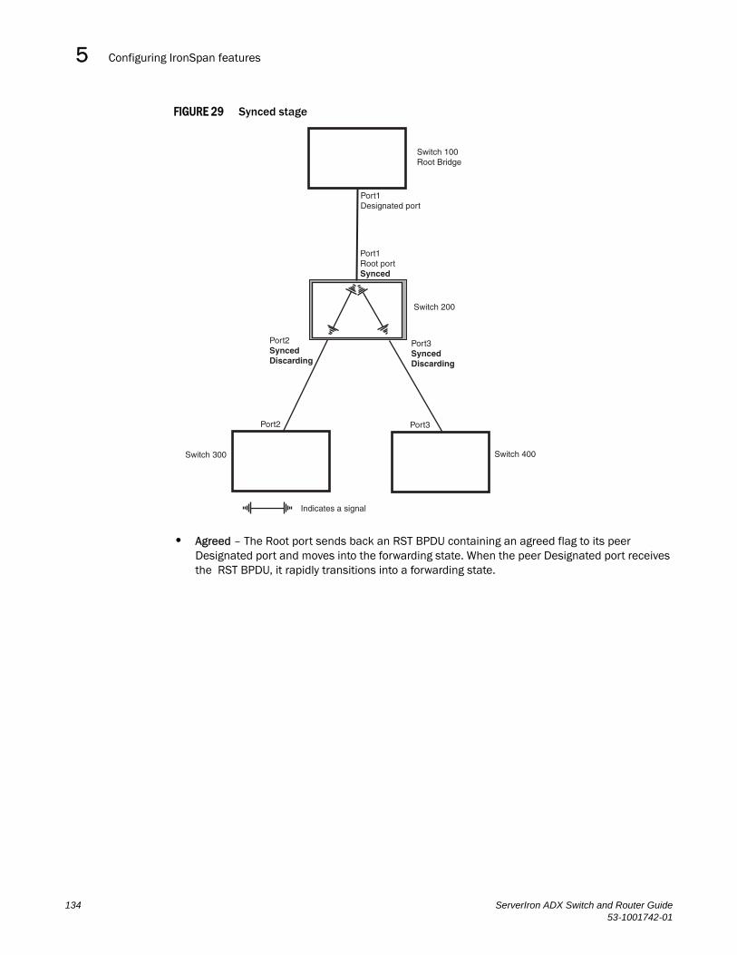
Configuring IronSpan features5DRAFT: BROCADE CONFIDENTIAL
FIGURE 29 Synced stage
• Agreed – The Root port sends back an RST BPDU containing an agreed flag to its peer Designated port and moves into the forwarding state. When the peer Designated port receives the RST BPDU, it rapidly transitions into a forwarding state.
BigIron
Switch 100Root Bridge
Switch 200
Switch 300 Switch 400
Port1Designated port
Port1Root portSynced
Port2 Port3
Indicates a signal
Port2SyncedDiscarding
Port3SyncedDiscarding
134 ServerIron ADX Switch and Router Guide53-1001742-01

Configuring IronSpan features 5DRAFT: BROCADE CONFIDENTIAL
FIGURE 30 Agree stage
At this point, the handshake mechanism is complete between Switch 100, the root bridge, and Switch 200.
Switch 200 updates the information on the Switch 200’s Designated ports (Port2 and Port3) and identifies the new root bridge. The Designated ports send RST BPDUs, containing proposal flags, to their downstream bridges, without waiting for the hello timers to expire on them. This process starts the handshake with the downstream bridges.
For example, Port2/Switch 200 sends an RST BPDU to Port2/Switch 300 that contains a proposal flag. Port2/Switch 300 asserts a proposed signal. Ports in Switch 300 then set sync signals on the ports to synchronize and negotiate their roles and states. Then the ports assert a synced signal and when the Root port in Switch 300 asserts it’s synced signal, it sends an RST BPDU to Switch 200 with an agreed flag.
This handshake is repeated between Switch 200 and Switch 400 until all Designated and Root ports are in forwarding states.
Handshake when a root port has been electedIf a non-root bridge already has a Root port, 802.1W uses a different type of handshake. For example, in Figure 31, a new root bridge is added to the topology.
BigIron
Switch 100Root Bridge
Port1Designated portForwarding
Port1Root portSyncedForwarding
RST BPDUsent with an Agreedflag
Switch 200
Switch 300 Switch 400
Indicates a signal
Port2SyncedDiscarding
Port3SyncedDiscarding
Port2 Port3
ServerIron ADX Switch and Router Guide 13553-1001742-01

Configuring IronSpan features5DRAFT: BROCADE CONFIDENTIAL
FIGURE 31 Addition of a new root bridge
The handshake that occurs between Switch 60 and Switch 100 follows the one described in the previous section (“Handshake when no root port is elected” on page 131). The former root bridge becomes a non-root bridge and establishes a Root port (Figure 32).
However, since Switch 200 already had a Root port in a forwarding state, 802.1W uses the Proposing -> Proposed -> Sync and Reroot -> Sync and Rerooted -> Rerooted and Synced -> Agreed handshake:
• Proposing and Proposed – The Designated port on the new root bridge (Port4/Switch 60) sends an RST BPDU that contains a proposing signal to Port4/Switch 200 to inform the port that it is ready to put itself in a forwarding state (Figure 32). 802.1W algorithm determines that the RST BPDU that Port4/Switch 200 received is superior to what it can generate, so Port4/Switch 200 assumes a Root port role.
Switch 100Port2
Designatedport
Switch 60
Port4Designated port
Port2
Port1
Port1Root port
Port4
Port3Port2
Switch 200
Port2 Port3
Switch 300 Switch 400
136 ServerIron ADX Switch and Router Guide53-1001742-01

Configuring IronSpan features 5DRAFT: BROCADE CONFIDENTIAL
FIGURE 32 New root bridge sending a proposal flag
• Sync and Reroot – The Root port then asserts a sync and a reroot signal on all the ports on the bridge. The signal tells the ports that a new Root port has been assigned and they are to renegotiate their new roles and states. The other ports on the bridge assert their sync and reroot signals. Information about the old Root port is discarded from all ports. Designated ports change into discarding states (Figure 33).
Switch 100Port2
Designatedport
Switch 60
Port1
Port2Root port
HandshakeCompleted
Port4Designated portProposing
Proposing
Port1Root portForwarding
RST BPDUsent with a Proposingflag
Port4Designated portProposed
Switch 200
Port2 Port3
Port2 Port3
Switch 300 Switch 400
ServerIron ADX Switch and Router Guide 13753-1001742-01

Configuring IronSpan features5DRAFT: BROCADE CONFIDENTIAL
FIGURE 33 Sync and reroot
• Sync and Rerooted – When the ports on Switch 200 have completed the reroot phase, they assert their rerooted signals and continue to assert their sync signals as they continue in their discarding states. They also continue to negotiate their roles and states with their peer ports (Figure 34).
BigIron
Switch 100
Port2Root port
Port2Designated
port
Port1
Switch 60
Port4Designated portProposing
Proposing Port1Root portSyncRerootForwarding
Port4Root portSyncRerootDiscardingPort3
SyncRerootDiscarding
Port2SyncRerootDiscarding
Switch 200
Switch 300 Switch 400
Port2 Port3
Indicates a signal
138 ServerIron ADX Switch and Router Guide53-1001742-01

Configuring IronSpan features 5DRAFT: BROCADE CONFIDENTIAL
FIGURE 34 Sync and rerooted
• Synced and Agree – When all the ports on the bridge assert their synced signals, the new Root port asserts its own synced signal and sends an RST BPDU to Port4/Switch 60 that contains an agreed flag (Figure 34). The Root port also moves into a forwarding state.
BigIron
Switch 100Port2
Designatedport
Switch 60
Port4Designated port
Port2Root port
Port1
Port1Designated portSyncRerootedDiscarding
Port4Root portSyncRerootedDiscardingPort3
SyncRerootedDiscarding
Port2SyncRerootedDiscarding
Switch 200
Proposing
Port2 Port3
Switch 300 Switch 400
Indicates an 802.1W signal controlled by the current Root port
ServerIron ADX Switch and Router Guide 13953-1001742-01
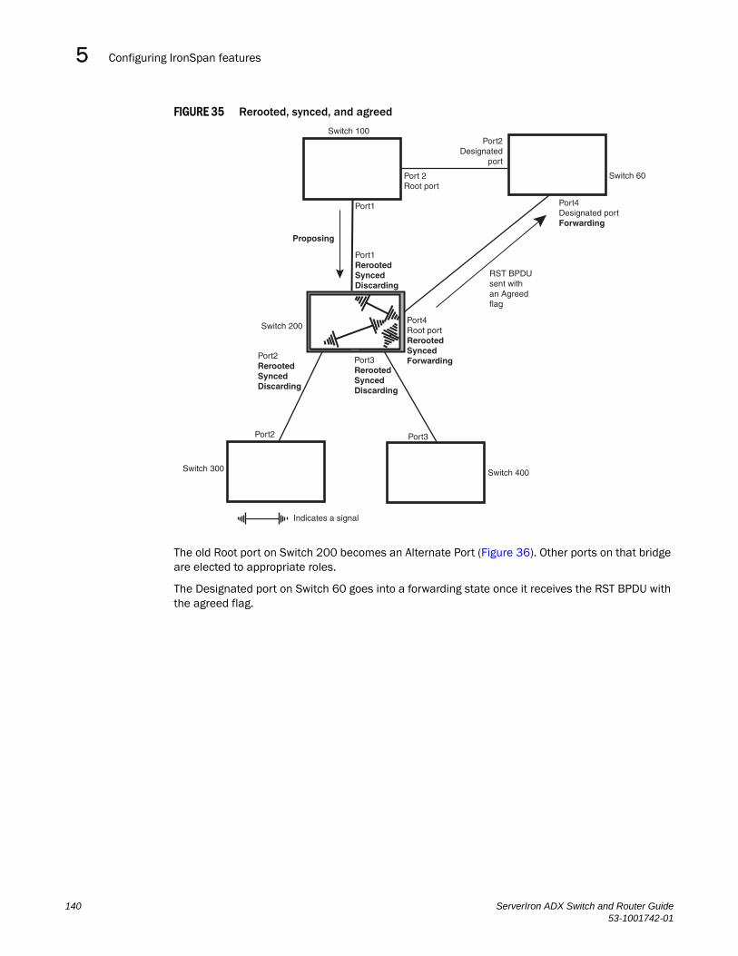
Configuring IronSpan features5DRAFT: BROCADE CONFIDENTIAL
FIGURE 35 Rerooted, synced, and agreed
The old Root port on Switch 200 becomes an Alternate Port (Figure 36). Other ports on that bridge are elected to appropriate roles.
The Designated port on Switch 60 goes into a forwarding state once it receives the RST BPDU with the agreed flag.
BigIron
Switch 100Port2
Designatedport
Switch 60
Port4Designated portForwarding
Port 2Root port
Port1
Proposing
Port1RerootedSyncedDiscarding
Port4Root portRerootedSyncedForwardingPort3
RerootedSyncedDiscarding
Port2RerootedSyncedDiscarding
Port2 Port3
Switch 300
Indicates a signal
Switch 200
Switch 400
RST BPDUsent with an Agreedflag
140 ServerIron ADX Switch and Router Guide53-1001742-01

Configuring IronSpan features 5DRAFT: BROCADE CONFIDENTIAL
FIGURE 36 Handshake completed after election of new root port
Recall that Switch 200 sent the agreed flag to Port4/Switch 60 and not to Port1/Switch 100 (the port that connects Switch 100 to Switch 200). Therefore, Port1/Switch 100 does not go into forwarding state instantly. It waits until two instances of the forward delay timer expires on the port before it goes into forwarding state.
At this point the handshake between the Switch 60 and Switch 200 is complete.
The remaining bridges (Switch 300 and Switch 400) may have to go through the reroot handshake if a new Root port needs to be assigned.
Convergence in a simple topology
The examples in this section illustrate how 802.1W convergence occurs in a simple Layer 2 topology at start-up.
NOTEThe remaining examples assume that the appropriate handshake mechanisms occur as port roles and states change.
Convergence at start upIn Figure 37, two bridges Switch 2 and Switch 3 are powered up. There are point-to-point connections between Port3/Switch 2 and Port3/Switch 3.
Switch 100Port2
Designatedport
Port2Root port
Switch 60
Port4Designated port
Port1
Proposing
Port1Alternate port
Port4Root port
Switch 200
Port2
Port2
Port3
Port3
Proposing Proposing
Switch 300 Switch 400
ServerIron ADX Switch and Router Guide 14153-1001742-01

Configuring IronSpan features5DRAFT: BROCADE CONFIDENTIAL
FIGURE 37 Convergence between two bridges
At power up, all ports on Switch 2 and Switch 3 assume Designated port roles and are at discarding states before they receive any RST BPDU.
Port3/Switch 2, with a Designated role, transmits an RST BPDU with a proposal flag to Port3/Switch 3. A ports with a Designated role sends the proposal flag in its RST BPDU when they are ready to move to a forwarding state.
Port3/Switch 3, which starts with a role of Designated port, receives the RST BPDU and finds that it is superior to what it can transmit; therefore, Port3/Switch 3 assumes a new port role, that of a Root port. Port3/Switch 3 transmits an RST BPDU with an agreed flag back to Switch 2 and immediately goes into a forwarding state.
Port3/Switch 2 receives the RST BPDU from Port3/Switch 3 and immediately goes into a forwarding state.
Now 802.1W has fully converged between the two bridges, with Port3/Switch 3 as an operational root port in forwarding state and Port3/Switch 2 as an operational Designated port in forwarding state.
Next, Switch 1 is powered up (Figure 38).
Bridge priority = 1500Switch 2
Port3Designatedport
Port3Root port
Switch 3Bridge priority = 2000
142 ServerIron ADX Switch and Router Guide53-1001742-01

Configuring IronSpan features 5DRAFT: BROCADE CONFIDENTIAL
FIGURE 38 Simple Layer 2 topology
The point-to-point connections between the three bridges are as follows:
• Port2/Switch 1 and Port2/Switch 2
• Port4/Switch 1 and Port4/Switch 3
• Port3/Switch 2 and Port3/Switch 3
Ports 3 and 5 on Switch 1 are physically connected together.
At start up, the ports on Switch 1 assume Designated port roles, which are in discarding state. They begin sending RST BPDUs with proposal flags to move into a forwarding state.
When Port4/Switch 3 receives these RST BPDUs 802.1W algorithm determines that they are better than the RST BPDUs that were previously received on Port3/Switch 3. Port4/Switch 3 is now selected as Root port. This new assignment signals Port3/Switch 3 to begin entering the discarding state and to assume an Alternate port role. As it goes through the transition, Port3/Switch 3 negotiates a new role and state with its peer port, Port3/Switch 2.
Port4/Switch 3 sends an RST BPDU with an agreed flag to Port4/Switch 1. Both ports go into forwarding states.
Port2/Switch 2 receives an RST BPDU. The 802.1W algorithm determines that these RST BPDUs that are superior to any that any port on Switch 2 can transmit; therefore, Port2/Switch 2 assumes the role of a Root port.
The new Root port then signals all ports on the bridge to start synchronization. Since none of the ports are Edge ports, they all enter the discarding state and assume the role of Designated ports. Port3/Switch 2, which previously had a Designated role with a forwarding state, starts the discarding state. They also negotiate port roles and states with their peer ports. Port3/Switch 2 also sends an RST BPU to Port3/Switch 3 with a proposal flag to request permission go into a forwarding state.
Switch 2
Switch 3
Switch 1
Port2Designated
port
Port4Designated port
Port3Designatedport
Port3Designatedport
Port5Backup port
Port3Alternateport
Port2Root port
Port4Root port
Bridge priority = 1500
Bridge priority = 2000
Bridge priority = 1000
ServerIron ADX Switch and Router Guide 14353-1001742-01

Configuring IronSpan features5DRAFT: BROCADE CONFIDENTIAL
The Port2/Switch 2 bridge also sends an RST BPDU with an agreed flag Port2/Switch 1 that Port2 is the new Root port. Both ports go into forwarding states.
Now, Port3/Switch 3 is currently in a discarding state and is negotiating a port role. It received RST BPDUs from Port3/Switch 2. The 802.1W algorithm determines that the RST BPDUs Port3/Switch 3 received are superior to those it can transmit; however, they are not superior to those that are currently being received by the current Root port (Port4). Therefore, Port3 retains the role of Alternate port.
Ports 3/Switch 1 and Port5/Switch 1 are physically connected. Port5/Switch 1 received RST BPDUs that are superior to those received on Port3/Switch 1; therefore, Port5/Switch 1 is given the Backup port role while Port3 is given the Designated port role. Port3/Switch 1, does not go directly into a forwarding state. It waits until the forward delay time expires twice on that port before it can proceed to the forwarding state.
Once convergence is achieved, the active Layer 2 forwarding path converges as shown in Figure 39.
FIGURE 39 Active Layer 2 path
Convergence after a link failure
What happens if a link in the 802.1W topology fails?
For example, Port2/Switch , which is the port that connects Switch 2 to the root bridge (Switch 1), fails. Both Switch 2 and Switch 1 notice the topology change (Figure 40).
Switch 2
Port2Root port
Port2Designated
port
Port3Designatedport
Switch 1Port5Backup port
Bridge priority = 1500 Bridge priority = 1000
Port4Designated port
Port4Root port
Port3Designatedport
Port3Alternateport
Bridge priority = 2000
Switch 3
Indicates the active Layer 2 path
144 ServerIron ADX Switch and Router Guide53-1001742-01

Configuring IronSpan features 5DRAFT: BROCADE CONFIDENTIAL
FIGURE 40 Link failure in the topology
Switch 1 sets its Port2 into a discarding state.
At the same time, Switch 2 assumes the role of a root bridge since its root port failed and it has no operational Alternate port. Port3/Switch 2, which currently has a Designated port role, sends an RST BPDU to Switch 3. The RST BPDU contains a proposal flag and a bridge ID of Switch 2 as its root bridge ID.
When Port3/Switch 3 receives the RST BPDUs, 802.1W algorithm determines that they are inferior to those that the port can transmit. Therefore, Port3/Switch 3 is given a new role, that of a Designated port. Port3/Switch 3 then sends an RST BPDU with a proposal flag to Switch 2, along with the new role information. However, the root bridge ID transmitted in the RST BPDU is still Switch 1.
When Port3/Switch 2 receives the RST BPDU, 802.1W algorithm determines that it is superior to the RST BPDU that it can transmit; therefore, Port3/Switch 2 receives a new role; that of a Root port. Port3/Switch 2 then sends an RST BPDU with an agreed flag to Port3/Switch 3. Port3/Switch 2 goes into a forwarding state.
When Port3/Switch 3 receives the RST BPDU that Port3/Switch 2 sent, Port3/Switch 3 changes into a forwarding state, which then completes the full convergence of the topology.
Convergence at link restoration
When Port2/Switch 2 is restored, both Switch 2 and Switch 1 recognize the change. Port2/Switch 1 starts assuming the role of a Designated port and sends an RST BPDU containing a proposal flag to Port2/Switch 2.
Bridge priority = 1500
Bridge priority = 2000
Bridge priority = 1000
Switch 2
Switch 3
Switch 1
Port2Port2
Port3
Port3
Port3
Port4
Port4
Port5
ServerIron ADX Switch and Router Guide 14553-1001742-01

Configuring IronSpan features5DRAFT: BROCADE CONFIDENTIAL
When Port2/Switch 2 receives the RST BPDUs, 802.1W algorithm determines that the RST BPDUs the port received are better than those received on Port3/Switch 3; therefore, Port2/Switch 2 is given the role of a Root port. All the ports on Switch 2 are informed that a new Root port has been assigned which then signals all the ports to synchronize their roles and states. Port3/Switch 2, which was the previous Root port, enters a discarding state and negotiates with other ports on the bridge to establish its new role and state, until it finally assumes the role of a Designated port.
Next, the following happens:
• Port3/Switch 2, the Designated port, sends an RST BPDU, with a proposal flag to Port3/Switch 3.
• Port2/Switch 2 also sends an RST BPDU with an agreed flag to Port2/Switch 1 and then places itself into a forwarding state.
When Port2/Switch 1 receives the RST BPDU with an agreed flag sent by Port2/Switch 2, it puts that port into a forwarding state. The topology is now fully converged.
When Port3/Switch 3 receives the RST BPDU that Port3/Switch 2 sent, 802.1W algorithm determines that these RST BPDUs are superior to those that Port3/Switch 3 can transmit. Therefore, Port3/Switch 3 is given a new role, that of an Alternate port. Port3/Switch 3 immediately enters a discarding state.
Now Port3/Switch 2 does not go into a forwarding state instantly like the Root port. It waits until the forward delay timer expires twice on that port while it is still in a Designated role, before it can proceed to the forwarding state. The wait, however, does not cause a denial of service, since the essential connectivity in the topology has already been established.
When fully restored, the topology is the same as that shown on Figure 38.
Convergence in a complex 802.1W topology
The following is an example of a complex 802.1W topology.
146 ServerIron ADX Switch and Router Guide53-1001742-01

Configuring IronSpan features 5DRAFT: BROCADE CONFIDENTIAL
FIGURE 41 Complex 802.1W topology
In Figure 41, Switch 5 is selected as the root bridge since it is the bridge with the highest priority. Lines in the figure show the point-to-point connection to the bridges in the topology.
Switch 5 sends an RST BPDU that contains a proposal flag to Port5/Switch 2. When handshakes are completed in Switch 5, Port5/Switch 2 is selected as the Root port on Switch 2. All other ports on Switch 2 are given Designated port role with discarding states.
Port5/Switch 2 then sends an RST BPDU with an agreed flag to Switch 5 to confirm that it is the new Root port and the port enters a forwarding state. Port7 and Port8 are informed of the identity of the new Root port. 802.1W algorithm selects Port7 as the Designated port while Port8 becomes the Backup port.
Port3/Switch 5 sends an RST BPDU to Port3/Switch 6 with a proposal flag. When Port3/Switch 5 receives the RST BPDU, handshake mechanisms select Port3 as the Root port of Switch 6. All other ports are given a Designated port role with discarding states. Port3/Switch 6 then sends an RST BPDU with an agreed flag to Port3/Switch 5 to confirm that it is the Root port. The Root port then goes into a forwarding state.
Now, Port4/Switch 6 receives RST BPDUs that are superior to what it can transmit; therefore, it is given the Alternate port role. The port remains in discarding state.
Port5/Switch 6 receives RST BPDUs that are inferior to what it can transmit. The port is then given a Designated port role.
Next Switch 2 sends RST BPDUs with a proposal flag to Port3/Switch 4. Port3 becomes the Root port for the bridge; all other ports are given a Designated port role with discarding states. Port3/Switch 4 sends an RST BPDU with an agreed flag to Switch 2 to confirm that it is the new Root port. The port then goes into a forwarding state.
Switch 1Bridge priority = 1000
Switch 2Bridge priority = 200
Switch 3Bridge priority = 300
Switch 4Bridge priority = 400
Switch 5Bridge priority = 60
Switch 6Bridge priority = 900
Port3 Port3
Port3 Port3
Port3
Port3
Port4 Port4
Port4
Port5 Port5
Port4
Port2
Port2
Port2 Port2
Port7
Port5
Port8
ServerIron ADX Switch and Router Guide 14753-1001742-01
Configuring IronSpan features5DRAFT: BROCADE CONFIDENTIAL
Now Port4/Switch 4 receives an RST BPDU that is superior to what it can transmit. The port is then given an Alternate port role, and remains in discarding state.
Likewise, Port5/Switch 4 receives an RST BPDU that is superior to what it can transmit. The port is also given an Alternate port role, and remains in discarding state.
Port2/Switch 2 transmits an RST BPDU with a proposal flag to Port2/Switch 1. Port2/Switch 1 becomes the Root port. All other ports on Switch 1 are given Designated port roles with discarding states.
Port2/Switch 1 sends an RST BPDU with an agreed flag to Port2/Switch 2 and Port2/Switch 1 goes into a forwarding state.
Port3/Switch 1 receives an RST BPDUs that is inferior to what it can transmit; therefore, the port retains its Designated port role and goes into forwarding state only after the forward delay timer expires twice on that port while it is still in a Designated role.
Port3/Switch 2 sends an RST BPDU to Port3/Switch 3 that contains a proposal flag. Port3/Switch 3 becomes the Root port, while all other ports on Switch 3 are given Designated port roles and go into discarding states. Port3/Switch 3 sends an RST BPDU with an agreed flag to Port3/Switch 2 and Port3/Switch 3 goes into a forwarding state.
Now, Port2/Switch 3 receives an RST BPDUs that is superior to what it can transmit so that port is given an Alternate port state.
Port4/Switch 3 receives an RST BPDU that is inferior to what it can transmit; therefore, the port retains its Designated port role.
Ports on all the bridges in the topology with Designated port roles that received RST BPDUs with agreed flags go into forwarding states instantly. However, Designated ports that did not receive RST BPDUs with agreed flags must wait until the forward delay timer expires twice on those port. Only then will these port move into forwarding states.
The entire 802.1W topology converges in less than 300 msec and the essential connectivity is established between the designated ports and their connected root ports.
After convergence is complete, Figure 42 shows the active Layer 2 path of the topology in Figure 41.
148 ServerIron ADX Switch and Router Guide53-1001742-01

Configuring IronSpan features 5DRAFT: BROCADE CONFIDENTIAL
FIGURE 42 Active Layer 2 path in complex topology
Propagation of topology change
The Topology Change state machine generates and propagates the topology change notification messages on each port. When a Root port or a Designated port goes into a forwarding state, the Topology Change state machine on those ports send a topology change notice (TCN) to all the bridges in the topology to propagate the topology change.
NOTEEdge ports, Alternate ports, or Backup ports do not need to propagate a topology change.
The TCN is sent in the RST BPDU that a port sends. Ports on other bridges in the topology then acknowledge the topology change once they receive the RST BPDU, and send the TCN to other bridges until all the bridges are informed of the topology change.
For example, Port3/Switch 2 in Figure 43, fails. Port4/Switch 3 becomes the new Root port. Port4/Switch 3 sends an RST BPDU with a TCN to Port4/Switch 4. To propagate the topology change, Port4/Switch 4 then starts a TCN timer on itself, on the bridge’s Root port, and on other ports on that bridge with a Designated role. Then Port3/Switch 4 sends RST BPDU with the TCN to Port4/Switch 2. (Note the new active Layer 2 path in Figure 43.)
Switch 1Bridge priority = 1000
Switch 2Bridge priority = 200
Switch 5Bridge priority = 60
Switch 3Bridge priority = 300
Switch 4Bridge priority = 400
Switch 6Bridge priority = 900
Port3
Port3
Port3
Port3 Port3
Port3
Port2 Port2Port2
Port2
Port4 Port4
Port4
Port4
Port5
Port5 Port5
Port7 Port8
Indicates the active Layer 2 path
ServerIron ADX Switch and Router Guide 14953-1001742-01

Configuring IronSpan features5DRAFT: BROCADE CONFIDENTIAL
FIGURE 43 Beginning of topology change notice
Switch 2 then starts the TCN timer on the Designated ports and sends RST BPDUs that contain the TCN as follows (Figure 44):
• Port5/Switch 2 sends the TCN to Port2/Switch 5
• Port4/Switch 2 sends the TCN to Port4/Switch 6
• Port2/Switch 2 sends the TCN to Port2/Switch 1
Switch 1Bridge priority = 1000
Switch 2Bridge priority = 200
Switch 5Bridge priority = 60
Switch 6Bridge priority = 900
Switch 4Bridge priority = 400
Switch 3Bridge priority = 300
Port2 Port2
Port2
Port2
Port3
Port3 Port3
Port3
Port3
Port3
Port4 Port4
Port4
Port4
Port5 Port 5
Port5
Port7 Port8
Indicates the active Layer 2 path
Indicates direction of TCN
150 ServerIron ADX Switch and Router Guide53-1001742-01

Configuring IronSpan features 5DRAFT: BROCADE CONFIDENTIAL
FIGURE 44 Sending TCN to bridges connected to Switch 2
Then FRY1, Switch 5, and Switch 6 send RST BPDUs that contain the TCN to Switch 3 and Switch 4 to complete the TCN propagation (Figure 45).
Switch 1Bridge priority = 1000
Switch 2Bridge priority = 200
Switch 5Bridge priority = 60
Switch 6Bridge priority = 900
Switch 4Bridge priority = 400
Switch 3Bridge priority = 300
Port3
Port3 Port3
Port3Port3
Port3
Port4 Port4
Port4
Port4
Port2 Port2 Port2
Port2
Port5 Port5
Port5
Indicates the active Layer 2 path
Indicates direction of TCN
Port 7 Port8
ServerIron ADX Switch and Router Guide 15153-1001742-01

Configuring IronSpan features5DRAFT: BROCADE CONFIDENTIAL
FIGURE 45 Completing the TCN propagation
Compatibility of 802.1W with 802.1D
802.1W-enabled bridges are backward compatible with IEEE 802.1D bridges. This compatibility is managed on a per-port basis by the Port Migration state machine. However, intermixing the two types of bridges in the network topology is not advisable if you want to take advantage of the rapid convergence feature.
Compatibility with 802.1D means that an 802.1W-enabled port can send BPDUs in the STP or 802.1D format when one of the following events occur:
• The port receives a legacy BPDU. A legacy BPDU is an STP BPDU or a BPDU in an 802.1D format. The port that receives the legacy BPDU automatically configures itself to behave like a legacy port. It sends and receives legacy BPDUs only.
• The entire bridge is configured to operate in an 802.1D mode when an administrator sets the
• bridge parameter to zero at the CLI, forcing all ports on the bridge to send legacy BPDUs only.
Once a port operates in the 802.1D mode, 802.1D convergence times are used and rapid convergence is not realized.
For example, in Figure 46, Switch 10 and Switch 30 receive legacy BPDUs from Switch 20. Ports on Switch 10 and Switch 30 begin sending BPDUs in STP format to allow them to operate transparently with Switch 20.
Switch 1Bridge priority = 1000
Switch 2Bridge priority = 200
Switch 5Bridge priority = 60
Switch 6Bridge priority = 900
Switch 4Bridge priority = 400
Switch 3Bridge priority = 300
Port3
Port3 Port3 Port3
Port3
Port2 Port2Port2
Port4 Port4
Port4
Port4Port3
Port2
Port5
Port5 Port5
Port7 Port8
Indicates the active Layer 2 path
Indicates direction of TCN
152 ServerIron ADX Switch and Router Guide53-1001742-01

Configuring IronSpan features 5DRAFT: BROCADE CONFIDENTIAL
FIGURE 46 802.1W bridges with an 802.1D bridge
Once Switch 20 is removed from the LAN, Switch 10 and Switch 30 receive and transmit BPDUs in the STP format to and from each other. This state will continue until the administrator enables the force-migration-check command to force the bridge to send RSTP BPDU during a migrate time period. If ports on the bridges continue to hear only STP BPDUs after this migrate time period, those ports will return to sending STP BPDUs. However, when the ports receive RST BPDUs during the migrate time period, the ports begin sending RST BPDUs. The migrate time period is non-configurable. It has a value of three seconds.
NOTEThe IEEE standards state that 802.1W bridges need to interoperate with 802.1D bridges. IEEE standards set the path cost of 802.1W bridges to be between 1 and 200,000,000; whereas path cost of 802.1D bridges are set between 1 and 65,535. In order for the two bridge types to be able to interoperate in the same topology, the administrator needs to configure the bridge path cost appropriately. Path costs for either 802.1W bridges or 802.1D bridges need to be changed; in most cases, path costs for 802.1W bridges need to be changed.
Configuring 802.1W parameters on a Brocade device
The remaining 802.1W sections explain how to configure the 802.1W protocol in a Brocade Layer 3 Switch.
s are shipped from the factory with 802.1W disabled. Use the following methods to enable or disable 802.1W. You can enable or disable 802.1W at the following levels:
• Port-based VLAN – Affects all ports within the specified port-based VLAN. When you enable or disable 802.1W within a port-based VLAN, the setting overrides the global setting. Thus, you can enable 802.1W for the ports within a port-based VLAN even when 802.1W is globally disabled, or disable the ports within a port-based VLAN when 802.1W is globally enabled.
• Individual port – Affects only the individual port. However, if you change the 802.1W state of the primary port in a trunk group, the change affects all ports in the trunk group.
Enabling or disabling 802.1W in a port-based VLAN Use the following procedure to disable or enable 802.1W on a device on which you have configured a port-based VLAN. Changing the 802.1W state in a VLAN affects only that VLAN.
To enable 802.1W for all ports in a port-based VLAN, enter commands such as the following.
ServerIron(config)# vlan 10ServerIron(config-vlan-10)# spanning-tree 802-1w
Switch 10 Switch 20 Switch 30
802.1W 802.1D 802.1W
ServerIron ADX Switch and Router Guide 15353-1001742-01

Configuring IronSpan features5DRAFT: BROCADE CONFIDENTIAL
Syntax: [no] spanning-tree 802-1w
Enabling or disabling 802.1W on a single spanning treeTo enable 802.1W for all ports of a single spanning tree, use the procedure in this section.
Enter a command such as the following.
ServerIron(config-vlan-10)# spanning-tree single 802-1w
Syntax: [no] spanning-tree single 802-1w
Disabling or enabling 802.1W on an individual portThe spanning-tree 802-1w or spanning-tree single 802-1w command must be used to initially enable 802.1W on ports. Both commands enable 802.1W on all ports that belong to the VLAN or to the single spanning tree.
Once 802.1W is enabled on a port, it can be disabled on individual ports. 802.1W that have been disabled on individual ports can then be enabled as required.
NOTEIf you change the 802.1W state of the primary port in a trunk group, the change affects all ports in that trunk group.
To disable or enable 802.1W on an individual port, enter commands such as the following.
ServerIron(config)# interface 1/1ServerIron(config-if-1/1)# no spanning-tree
Syntax: [no] spanning-tree
Changing 802.1W bridge parametersWhen you make changes to 802.1W bridge parameters, the changes are applied to individual ports on the bridge. To change 802.1W bridge parameters, use the following method.
To designate a priority for a bridge, enter a command such as the following.
ServerIron(config)# spanning-tree 802-1w priority 10
The command in this example changes the priority on a device on which you have not configured port-based VLANs. The change applies to the default VLAN. If you have configured a port-based VLAN on the device, you can configure the parameters only at the configuration level for individual VLANs. Enter commands such as the following.
ServerIron(config)# vlan 20ServerIron(config-vlan-20)# spanning-tree 802-1w priority 0
To make this change in the default VLAN, enter the following commands.
ServerIron(config)# vlan 1ServerIron(config-vlan-1)# spanning-tree 802-1w priority 0
Syntax: spanning-tree 802-1w [forward-delay <value>] | [hello-time <value>] | [max-age <time>] | [force-version <value>] | [priority <value>]
The forward-delay <value> parameter specifies how long a port waits before it forwards an RST BPDU after a topology change. This can be a value from 4 – 30 seconds. The default is 15 seconds.
The hello-time <value> parameter specifies the interval between two hello packets. This parameter can have a value from 1 – 10 seconds. The default is 2 seconds.
154 ServerIron ADX Switch and Router Guide53-1001742-01

Configuring IronSpan features 5DRAFT: BROCADE CONFIDENTIAL
The max-age <value> parameter specifies the amount of time the device waits to receive a hello packet before it initiates a topology change. You can specify a value from 6 – 40 seconds. The default is 20 seconds.
The value of max-age must be greater than the value of forward-delay to ensure that the downstream bridges do not age out faster than the upstream bridges (those bridges that are closer to the root bridge).
The force-version <value> parameter forces the bridge to send BPDUs in a specific format. You can specify one of the following values:
• 0 – The STP compatibility mode. Only STP (or legacy) BPDUs will be sent.
• 2 – The default. RST BPDUs will be sent unless a legacy bridge is detected. If a legacy bridge is detected, STP BPDUs will be sent instead.
The default is 2.
The priority <value> parameter specifies the priority of the bridge. You can enter a value from 0 – 65535. A lower numerical value means a the bridge has a higher priority. Thus, the highest priority is 0. The default is 32768.
You can specify some or all of these parameters on the same command line. If you specify more than one parameter, you must specify them in the order shown above, from left to right.
Changing port parameters The 802.1W port commands can be enabled on individual ports or on multiple ports, such as all ports that belong to a VLAN.
The 802.1W port parameters are preconfigured with default values. If the default parameters meet your network requirements, no other action is required.
You can change the following 802.1W port parameters using the following method.
ServerIron(config)# vlan 10ServerIron(config-vlan-10)# spanning-tree 802-1w ethernet 1/5 path-cost 15 priority 64
Syntax: spanning-tree 802-1w ethernet <portnum> path-cost <value> | priority <value> | [admin-edge-port] | [admin-pt2pt-mac] | [force-migration-check]
The ethernet parameter specifies the interface used.
The path-cost <value> parameter specifies the cost of the port’s path to the root bridge. 802.1W prefers the path with the lowest cost. You can specify a value from 1 – 20,000,000. Table 14 shows the recommended path cost values from the IEEE standards.
TABLE 14 Recommended path cost values of 802.1W
Link speed Recommended (default) 802.1W path cost values
Recommended 802.1W path cost range
Less than 100 kilobits per second
200,000,000 20,000,000 – 200,000,000
1 Megabit per second 20,000,000 2,000,000 – 200,000,000
10 Megabits per second 2,000,000 200,000 – 200,000,000
100 Megabits per second 200,000 20,000 – 200,000,000
1 Gigabit per second 20,000 2,000 – 200,000,000
10 Gigabits per second 2,000 200 – 20,000
ServerIron ADX Switch and Router Guide 15553-1001742-01

Configuring IronSpan features5DRAFT: BROCADE CONFIDENTIAL
The priority <value> parameter specifies the preference that 802.1W gives to this port relative to other ports for forwarding traffic out of the topology. You can specify a value from 8 – 252, in increments of 4. If you enter a value that is not divisible by four the software rounds to the nearest value that is. The default is 128. A higher numerical value means a lower priority; thus, the highest priority is 8
Set the admin-edge-port to enabled or disabled. If set to enabled, then the port becomes an edge port in the domain.
Set the admin-pt2pt-mac to enabled or disabled. If set to enabled, then a port is connected to another port through a point-to-point link. The point-to-point link increases the speed of convergence. This parameter, however, does not auto-detect whether or not the link is a physical point-to-point link.
The force-migration-check parameter forces the specified port to sent one RST BPDU. If only STP BPDUs are received in response to the sent RST BPDU, then the port will go return to sending STP BPDUs.
Example
Suppose you want to enable 802.1W on a system with no active port-based VLANs and change the hello-time from the default value of 2 to 8 seconds. Additionally, suppose you want to change the path and priority costs for port 5 only. To do so, enter the following commands.
ServerIron(config)# spanning-tree 802-1w hello-time 8 ServerIron(config)# spanning-tree 802-1w ethernet 5 path-cost 15 priority 64
Displaying information about 802-1W
To display a summary of 802-1W, use the following command.
100 Gigabits per second 200 20 – 2,000
1 Terabits per second 20 2 – 200
10 Terabits per second 2 1 – 20
TABLE 14 Recommended path cost values of 802.1W (Continued)
Link speed Recommended (default) 802.1W path cost values
Recommended 802.1W path cost range
156 ServerIron ADX Switch and Router Guide53-1001742-01

Configuring IronSpan features 5DRAFT: BROCADE CONFIDENTIAL
Syntax: show 802-1w [vlan <vlan-id>]
The vlan <vlan-id> parameter displays 802.1W information for the specified port-based VLAN.
The show 802.1w display command shows the information listed in Table 15.
TABLE 15 CLI display of 802.1W summary
This field... Displays...
VLAN ID The port-based VLAN that owns the STP instance. VLAN 1 is the default VLAN. If you have not configured port-based VLANs on this device, all 802.1W information is for VLAN 1.
Bridge IEEE 802.1W Parameters
Bridge Identifier The ID of the bridge.
Bridge Max Age The configured max age for this bridge. The default is 20.
Bridge Hello The configured hello time for this bridge.The default is 2.
Bridge FwdDly The configured forward delay time for this bridge. The default is 15.
Force-Version The configured force version value. One of the following value is displayed:• 0 – The bridge has been forced to operate in an STP compatibility mode. • 2 – The bridge has been forced to operate in an 802.1W mode. (This is
the default.)
txHoldCnt The number of BPDUs that can be transmitted per Hello Interval. The default is 3.
Root Bridge Identifier ID of the Root bridge that is associated with this bridge
Root Path Cost The cost to reach the root bridge from this bridge. If the bridge is the root bridge, then this parameter shows a value of zero.
Designated Bridge Identifier The bridge from where the root information was received.It can be from the root bridge itself, but it could also be from another bridge.
ServerIron(config)#show 802-1w --- VLAN 1 [ STP Instance owned by VLAN 1 ] ----------------------------VLAN 1 BPDU cam_index is 2 and the IGC and DMA master Are(HEX) 0 1 2 3Bridge IEEE 802.1W Parameters:Bridge Bridge Bridge Bridge Force txIdentifier MaxAge Hello FwdDly Version Holdhex sec sec sec cnt800000e080541700 20 2 15 Default 3
RootBridge RootPath DesignatedBri- Root Max Fwd HelIdentifier Cost dge Identifier Port Age Dly lohex hex sec sec sec800000e0804c9c00 200000 800000e0804c9c00 1 20 15 2
Port IEEE 802.1W Parameters: <--- Config Params -->|<-------------- Current state ----------------->Port Pri PortPath P2P Edge Role State Designa- DesignatedNum Cost Mac Port ted cost bridge1 128 200000 F F ROOT FORWARDING 0 800000e0804c9c002 128 200000 F F DESIGNATED FORWARDING 200000 800000e0805417003 128 200000 F F DESIGNATED FORWARDING 200000 800000e0805417004 128 200000 F F BACKUP DISCARDING 200000 800000e080541700
ServerIron ADX Switch and Router Guide 15753-1001742-01

Configuring IronSpan features5DRAFT: BROCADE CONFIDENTIAL
Root Port The port on which the root information was received. This is the port that is connected to the Designated Bridge.
Max Age The max age is derived from the Root port. An 802.1W-enabled bridge uses this value, along with the hello and message age parameters to compute the effective age of an RST BPDU.The message age parameter is generated by the Designated port and transmitted in the RST BPDU. RST BPDUs transmitted by a Designated port of the root bridge contains a message value of zero.Effective age is the amount of time the Root port, Alternate port, or Backup port retains the information it received from its peer Designated port. Effective age is reset every time a port receives an RST BPDU from its Designated port. If a Root port does not receive an RST BPDU from its peer Designated port for a duration more than the effective age, the Root port ages out the existing information and recomputes the topology.If the port is operating in 802.1D compatible mode, then max age functionality is the same as in 802.1D (STP).
Fwd Dly The number of seconds a non-edge Designated port waits until it can apply any of the following transitions, if the RST BPDU it receives does not have an agreed flag: • Discarding state to learning state• Learning state to forwarding stateWhen a non-edge port receives the RST BPDU it goes into forwarding state within 4 seconds or after two hello timers expire on the port. Fwd Dly is also the number of seconds that a Root port waits for an RST BPDU with a proposal flag before it applies the state transitions listed above. If the port is operating in 802.1D compatible mode, then forward delay functionality is the same as in 802.1D (STP).
Hello The hello value derived from the Root port. It is the number of seconds between two Hello packets.
Port IEEE 802.1W Parameters
Port Num The port number shown in a slot#/port# format.
Pri The configured priority of the port. The default is 128 or 0x80.
Port Path Cost The configured path cost on a link connected to this port.
P2P Mac Indicates if the point-to-point-mac parameter is configured to be a point-to-point link:• T – The link is configured as a point-to-point link. • F – The link is not configured as a point-to-point link. This is the default.
Edge port Indicates if the port is configured as an operational Edge port:• T – The port is configured as an Edge port.• F – The port is not configured as an Edge port. This is the default.
Role The current role of the port:• Root • Designated • Alternate • Backup• Disabled Refer to “Bridges and bridge port roles” on page 125 for definitions of the roles.
TABLE 15 CLI display of 802.1W summary (Continued)
This field... Displays...
158 ServerIron ADX Switch and Router Guide53-1001742-01

Configuring IronSpan features 5DRAFT: BROCADE CONFIDENTIAL
To display detailed information about 802-1W, using the following command.
Syntax: show 802-1w detail [vlan <vlan-id>]
The vlan <vlan-id> parameter displays 802.1W information for the specified port-based VLAN.
The show spanning-tree 802.1W command shows the following information.
State The port’s current 802.1W state. A port can have one of the following states:• Forwarding• Discarding • Learning • DisabledRefer to “Bridge port states” on page 129 and “Edge port and non-edge port states” on page 130.
Designated Cost The best root path cost that this port received, including the best root path cost that it can transmit.
Designated Bridge The ID of the bridge that sent the best RST BPDU that was received on this port.
This field... Displays...
VLAN ID ID of the VLAN that owns the instance of 802.1W and whether or not it is active.
Bridge ID ID of the bridge.
forceVersion the configured version of the bridge:• 0 – The bridge has been forced to operate in an STP compatible mode.• 2 – The bridge has been forced to operate in an 802.1W mode.
txHoldCount The number of BPDUs that can be transmitted per Hello Interval. The default is 3.
Port ID of the port in slot#/port# format.
TABLE 15 CLI display of 802.1W summary (Continued)
This field... Displays...
ServerIron(config)#show 802-1w detail ======================================================================VLAN 1 - MULTIPLE SPANNING TREE (MSTP - IEEE 802.1W) ACTIVE======================================================================BridgeId 800000e080541700, forceVersion 2, txHoldCount 3Port 1 - Role: ROOT - State: FORWARDING PathCost 200000, Priority 128, AdminOperEdge F, AdminPt2PtMac F DesignatedPriority - Root: 0x800000e0804c9c00, Bridge: 0x800000e080541700 ActiveTimers - rrWhile 4 rcvdInfoWhile 4 MachineStates - PIM: CURRENT, PRT: ROOT_PORT, PST: FORWARDING TCM: ACTIVE, PPM: SENDING_STP, PTX: TRANSMIT_IDLE Received - RST BPDUs 0, Config BPDUs 1017, TCN BPDUs 0
Port 2 - Role: DESIGNATED - State: FORWARDING PathCost 200000, Priority 128, AdminOperEdge F, AdminPt2PtMac F DesignatedPriority - Root: 0x800000e0804c9c00, Bridge: 0x800000e080541700 ActiveTimers - helloWhen 0 MachineStates - PIM: CURRENT, PRT: DESIGNATED_PORT, PST: FORWARDING TCM: ACTIVE, PPM: SENDING_RSTP, PTX: TRANSMIT_IDLE Received - RST BPDUs 0, Config BPDUs 0, TCN BPDUs 0
ServerIron ADX Switch and Router Guide 15953-1001742-01

Configuring IronSpan features5DRAFT: BROCADE CONFIDENTIAL
Role The current role of the port:• Root • Designated • Alternate • Backup• Disabled Refer to “Bridges and bridge port roles” on page 125 for definitions of the roles.
State The port’s current 802.1W state. A port can have one of the following states:• Forwarding• Discarding • Learning • DisabledRefer to “Bridge port states” on page 129 and “Edge port and non-edge port states” on page 130.
Path Cost The configured path cost on a link connected to this port.
Priority The configured priority of the port. The default is 128 or 0x80.
AdminOperEdge Indicates if the port is an operational Edge port. Edge ports may either be auto-detected or configured (forced) to be Edge ports using the CLI:• T – The port is and Edge port.• F – The port is not an Edge port. This is the default.
AdminP2PMac Indicates if the point-to-point-mac parameter is configured to be a point-to-point link:• T – The link is a point-to-point link• F – The link is not a point-to-point link. This is the default.
DesignatedPriority Shows the following:• Root – Shows the ID of the root bridge for this bridge.• Bridge – Shows the ID of the Designated bridge that is associated with this port.
ActiveTimers Shows what timers are currently active on this port and the number of seconds they have before they expire:• rrWhile – Recent root timer. A non-zero value means that the port has recently been a
Root port. • rcvdInfoWhile – Received information timer. Shows the time remaining before the
information held by this port expires (ages out). This timer is initialized with the effective age parameter. (Refer to “Max Age” on page 158.)
• rbWhile – Recent backup timer. A non-zero value means that the port has recently been a Backup port.
• helloWhen – Hello period timer. The value shown is the amount of time between hello messages.
• tcWhile – Topology change timer. The value shown is the interval when topology change notices can be propagated on this port.
• fdWhile – Forward delay timer. (Refer to the explanation for Fwd Dly on page 158.)• mdelayWhile – Migration delay timer. The amount of time that a bridge on the same
LAN has to synchronize its migration state with this port before another BPDU type can cause this port to change the BPDU that it transmits.
This field... Displays...
160 ServerIron ADX Switch and Router Guide53-1001742-01
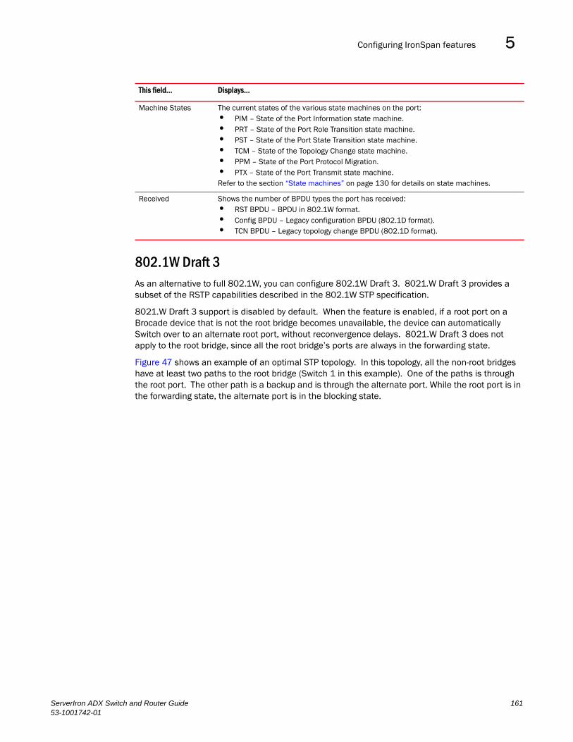
Configuring IronSpan features 5DRAFT: BROCADE CONFIDENTIAL
802.1W Draft 3As an alternative to full 802.1W, you can configure 802.1W Draft 3. 8021.W Draft 3 provides a subset of the RSTP capabilities described in the 802.1W STP specification.
8021.W Draft 3 support is disabled by default. When the feature is enabled, if a root port on a Brocade device that is not the root bridge becomes unavailable, the device can automatically Switch over to an alternate root port, without reconvergence delays. 8021.W Draft 3 does not apply to the root bridge, since all the root bridge’s ports are always in the forwarding state.
Figure 47 shows an example of an optimal STP topology. In this topology, all the non-root bridges have at least two paths to the root bridge (Switch 1 in this example). One of the paths is through the root port. The other path is a backup and is through the alternate port. While the root port is in the forwarding state, the alternate port is in the blocking state.
Machine States The current states of the various state machines on the port:• PIM – State of the Port Information state machine. • PRT – State of the Port Role Transition state machine. • PST – State of the Port State Transition state machine.• TCM – State of the Topology Change state machine. • PPM – State of the Port Protocol Migration. • PTX – State of the Port Transmit state machine. Refer to the section “State machines” on page 130 for details on state machines.
Received Shows the number of BPDU types the port has received:• RST BPDU – BPDU in 802.1W format. • Config BPDU – Legacy configuration BPDU (802.1D format). • TCN BPDU – Legacy topology change BPDU (802.1D format).
This field... Displays...
ServerIron ADX Switch and Router Guide 16153-1001742-01

Configuring IronSpan features5DRAFT: BROCADE CONFIDENTIAL
FIGURE 47 802.1W Draft 3 RSTP ready for failover
If the root port on a Switch becomes unavailable, 8021.W Draft 3 immediately fails over to the alternate port, as shown in Figure 48.
Switch 1 Switch 2
Switch 4Switch 3
Root BridgeBridge priority = 2 Bridge priority = 4
Root port = 2/2Alternate = 2/3, 2/4
Bridge priority = 8Root port = 4/4Alternate = 4/3
Bridge priority = 6Root port = 3/3Alternate = 3/4
Port 1/2FWD
Port 1/4FWD
Port 1/3FWD
Port 3/3FWD
Port 3/4BLK
Port 4/4FWD
Port 4/3BLK
Port 2/3FWD
Port 2/4FWD
Port 2/2FWD
The arrow shows the pathto the root bridge
162 ServerIron ADX Switch and Router Guide53-1001742-01

Configuring IronSpan features 5DRAFT: BROCADE CONFIDENTIAL
FIGURE 48 802.1W Draft 3 RSTP failover to alternate root port
In this example, port 3/3 on Switch 3 has become unavailable. In standard STP (802.1D), if the root port becomes unavailable, the Switch must go through the listening and learning stages on the alternate port to reconverge with the spanning tree. Thus, port 3/4 must go through the listening and learning states before entering the forwarding state and thus reconverging with the spanning tree.
8021.W Draft 3 avoids the reconvergence delay by calculating an alternate root port, and immediately failing over to the alternate port if the root port becomes unavailable. The alternate port is in the blocking state as long as the root port is in the forwarding state, but moves immediately to the active state if the root port becomes unavailable. Thus, using 8021.W Draft 3, Switch 3 immediately fails over to port 3/4, without the delays caused by the listening and learning states.
8021.W Draft 3 selects the port with the next-best cost to the root bridge. For example, on Switch 3, port 3/3 has the best cost to the root bridge and thus is selected by STP as the root port. Port 3/4 has the next-best cost to the root bridge, and thus is selected by 8021.W Draft 3 as the alternate path to the root bridge.
Once a failover occurs, the Switch no longer has an alternate root port. If the port that was an alternate port but became the root port fails, standard STP is used to reconverge with the network. You can minimize the reconvergence delay in this case by setting the forwarding delay on the root bridge to a lower value. For example, if the forwarding delay is set to 15 seconds (the default), change the forwarding delay to a value from 3 – 10 seconds.
X
The arrow shows the pathto the root bridge
Switch 1 Switch 2
Switch 4Switch 3
Port 1/2FWD
Port 2/2FWD
Port 1/4FWD
Port 2/4FWD
Port 1/3DISABLED
Root BridgeBridge priority = 2
Bridge priority = 6Root port = 3/4
Bridge priority = 8Root port = 4/4Alternate = 4/3
Bridge priority = 4Root port = 2/2Alternate = 2/3, 2/4
Port 2/3FWD
Port 4/3BLK
Port 4/4FWD
Port 3/4FWD
Port 3/3unavailable
ServerIron ADX Switch and Router Guide 16353-1001742-01

Configuring IronSpan features5DRAFT: BROCADE CONFIDENTIAL
During failover, 8021.W Draft 3 flushes the MAC addresses leaned on the unavailable root port, selects the alternate port as the new root port, and places that port in the forwarding state. If traffic is flowing in both directions on the new root port, addresses are flushed (moved) in the rest of the spanning tree automatically.
Reconvergence time
Spanning tree reconvergence using 8021.W Draft 3 can occur within one second.
After the spanning tree reconverges following the topology change, traffic also must reconverge on all the bridges attached to the spanning tree. This is true regardless of whether 8021.W Draft 3 or standard STP is used to reconverge the spanning tree.
Traffic reconvergence happens after the spanning tree reconvergence, and is achieved by flushing the Layer 2 information on the bridges.
• Following 8021.W Draft 3 reconvergence of the spanning tree, traffic reconvergence occurs in the time it takes for the bridge to detect the link changes plus the STP maximum age set on the bridge.
• If standard STP reconvergence occurs instead, traffic reconvergence takes two times the forward delay plus the maximum age.
NOTE8021.W Draft 3 does not apply when a failed root port comes back up. In this case, standard STP is used.
Configuration considerations
8021.W Draft 3 is disabled by default. To ensure optimal performance of the feature before you enable it:
• Configure the bridge priorities so that the root bridge is one that supports 8021.W Draft 3. (Use a Brocade device or third-party device that supports 8021.W Draft 3.)
• Change the forwarding delay on the root bridge to a value lower than the default 15 seconds. Brocade recommends a value from 3 – 10 seconds. The lower forwarding delay helps reduce reconvergence delays in cases where 8021.W Draft 3 is not applicable, such as when a failed root port comes back up.
• Configure the bridge priorities and root port costs so that each device has an active path to the root bridge if its root port becomes unavailable. For example, port 3/4 is connected to port 2/4 on Switch 2, which has the second most favorable bridge priority in the spanning tree.
NOTEIf reconvergence involves changing the state of a root port on a bridge that supports 802.1D STP but not 8021.W Draft 3, then reconvergence still requires the amount of time it takes for the ports on the 802.1D bridge to change state to forwarding (as needed), and receive BPDUs from the root bridge for the new topology.
Enabling 8021.W Draft 3
8021.W Draft 3 is disabled by default. The procedure for enabling the feature differs depending on whether single STP is enabled on the device.
164 ServerIron ADX Switch and Router Guide53-1001742-01

Configuring IronSpan features 5DRAFT: BROCADE CONFIDENTIAL
NOTESTP must be enabled before you can enable 8021.W Draft 3.
Enabling 8021.W Draft 3 when single STP Is not enabledTo enable 8021.W Draft 3 on a device that is not running single STP, use the following method.
By default, each port-based VLAN on the device has its own spanning tree. To enable 8021.W Draft 3 in a port-based VLAN, enter commands such as the following.
ServerIron(config)# vlan 10ServerIron(config-vlan-10)# spanning-tree rstp
Syntax: [no] spanning-tree rstp
This command enables 8021.W Draft 3. You must enter the command separately in each port-based VLAN in which you want to run 8021.W Draft 3.
NOTEThis command does not also enable STP. To enable STP, first enter the spanning-tree command without the rstp parameter. After you enable STP, enter the spanning-tree rstp command to enable 8021.W Draft 3.
To disable 8021.W Draft 3, enter the following command.
ServerIron(config-vlan-10)# no spanning-tree rstp
Enabling 8021.W Draft 3 when single STP Is enabledTo enable 8021.W Draft 3 on a device that is running single STP, enter the following command at the global CONFIG level of the CLI.
ServerIron(config)# spanning-tree single rstp
Syntax: [no] spanning-tree single rstp
This command enables 8021.W Draft 3 on the whole device.
NOTEThis command does not also enable single STP. To enable single STP, first enter the spanning-tree single command without the rstp parameter. After you enable single STP, enter the spanning-tree single rstp command to enable 8021.W Draft 3.
To disable 8021.W Draft 3 on a device that is running single STP, enter the following command.
ServerIron(config)# no spanning-tree single rstp
Single Spanning Tree (SSTP)By default, each port-based VLAN on a Brocade device runs a separate spanning tree, which you can enable or disable on an individual VLAN basis.
Alternatively, you can configure a Brocade device to run a single spanning tree across all ports and VLANs on the device. The Single STP feature (SSTP) is especially useful for connecting a Brocade device to third-party devices that run a single spanning tree in accordance with the 802.1q specification.
SSTP uses the same parameters, with the same value ranges and defaults, as the default STP support on Brocade devices. Refer to “STP parameters and defaults” on page 108.
ServerIron ADX Switch and Router Guide 16553-1001742-01

Configuring IronSpan features5DRAFT: BROCADE CONFIDENTIAL
SSTP defaults
SSTP is disabled by default. When you enable the feature, all VLANs on which STP is enabled become members of a single spanning tree. All VLANs on which STP is disabled are excluded from the single spanning tree.
• To add a VLAN to the single spanning tree, enable STP on that VLAN.
• To remove a VLAN from the single spanning tree, disable STP on that VLAN.
When you enable SSTP, all the ports that are in port-based VLANs with STP enabled become members of a single spanning tree domain. Thus, the ports share a single BPDU broadcast domain. The Brocade device places all the ports in a non-configurable VLAN, 4094, to implement the SSTP domain. However, this VLAN does not affect port membership in the port-based VLANs you have configured. Other broadcast traffic is still contained within the individual port-based VLANs. Therefore, you can use SSTP while still using your existing VLAN configurations without changing your network. In addition, SSTP does not affect 802.1q tagging. Tagged and untagged ports alike can be members of the single spanning tree domain.
NOTEWhen SSTP is enabled, the BPDUs on tagged ports go out untagged.
If you disable SSTP, all VLANs that were members of the single spanning tree run MSTP instead. In MSTP, each VLAN has its own spanning tree. VLANs that were not members of the single spanning tree were not enabled for STP. Therefore, STP remains disabled on those VLANs.
Enabling SSTP
To enable SSTP, use one of the following methods.
NOTEIf the device has only one port-based VLAN (the default VLAN), then the device is already running a single instance of STP. In this case, you do not need to enable SSTP. You need to enable SSTP only if the device contains more than one port-based VLAN and you want all the ports to be in the same STP broadcast domain.
To configure the Brocade device to run a single spanning tree, enter the following command at the global CONFIG level.
ServerIron(config)# spanning-tree single
NOTEIf the device has only one port-based VLAN, the CLI command for enabling SSTP is not listed in the CLI. The command is listed only if you have configured a port-based VLAN.
To change a global STP parameter, enter a command such as the following at the global CONFIG level.
ServerIron(config) spanning-tree single priority 2
This command changes the STP priority for all ports to 2.
To change an STP parameter for a specific port, enter commands such as the following.
ServerIron(config) spanning-tree single ethernet 1/1 priority 10
The commands shown above override the global setting for STP priority and set the priority to 10 for port 1/1.
166 ServerIron ADX Switch and Router Guide53-1001742-01

STP per VLAN group 5DRAFT: BROCADE CONFIDENTIAL
Here is the syntax for the global STP parameters.
Syntax: [no] spanning-tree single [forward-delay <value>] [hello-time <value>] | [maximum-age <time>] | [priority <value>]
Here is the syntax for the STP port parameters.
Syntax: [no] spanning-tree single [ethernet <portnum> path-cost <value> | priority <value>]
NOTEBoth commands listed above are entered at the global CONFIG level.
Displaying SSTP information
To verify that SSTP is in effect, enter the following commands at any level of the CLI.
ServerIron(config)# show span
Syntax: show span [vlan <vlan-id>] | [pvst-mode] | [<num>] | [detail [vlan <vlan-id> [atm <portnum> | ethernet <portnum> ] | <num>]]
The vlan <vlan-id> parameter displays STP information for the specified port-based VLAN.
The pvst-mode parameter displays STP information for the device’s Per VLAN Spanning Tree (PVST+) compatibility configuration.
The <num> parameter displays only the entries after the number you specify. For example, on a device with three port-based VLANs, if you enter 1, then information for the second and third VLANs is displayed, but information for the first VLAN is not displayed. Information is displayed according to VLAN number, in ascending order. The entry number is not the same as the VLAN number. For example, if you have port-based VLANs 1, 10, and 2024, then the command output has three STP entries. To display information for VLANs 10 and 2024 only, enter show span 1.
The detail parameter and its additional optional parameters display detailed information for individual ports. Refer to “Displaying detailed STP information for each interface” on page 117.
STP per VLAN groupSTP per VLAN group is an STP enhancement that provides scalability while overcoming the limitations of the following scalability alternatives:
• Standard STP – You can configure only 128 instances of standard STP on a Brocade device. It is possible to need more instances of STP than this in large configurations. Using STP per VLAN group, you can aggregate STP instances.
• Single STP – Single STP allows all the VLANs to run STP, but each VLAN runs the same instance of STP, resulting in numerous blocked ports that do not pass any Layer 2 traffic. STP per VLAN group uses all available links by load balancing traffic for different instances of STP on different ports. A port that blocks traffic for one spanning tree forwards traffic for another spanning tree.
STP per VLAN group allows you to group VLANs and apply the same STP parameter settings to all the VLANs in the group. Figure 49 shows an example of a STP per VLAN group implementation.
ServerIron ADX Switch and Router Guide 16753-1001742-01

STP per VLAN group5DRAFT: BROCADE CONFIDENTIAL
FIGURE 49 STP per VLAN group example
A master VLAN contains one or more member VLANs. Each of the member VLANs in a master VLAN runs the same instance of STP and uses the STP parameters configured for the master VLAN. In this example, the Brocade device is configured with VLANs 3, 4, 13, and 14. VLANs 3 and 4 are grouped in master VLAN 2, which is in STP group 1. VLANs 13 and 14 are grouped in master VLAN 12, which is in STP group 2. The VLANs in STP group 1 all share the same spanning tree. The VLANs in STP group 2 share a different spanning tree.
All the ports in the VLANs are tagged. The ports must be tagged so that they can be in both a member VLAN and the member's master VLAN. For example, ports 1/1 – 1/4 are in member VLAN 3 and also in master VLAN 2 (since master VLAN 2 contains member VLAN 3).
STP load balancing
Notice that the STP groups each have different STP priorities. In configurations that use the STP groups on multiple devices, you can use the STP priorities to load balance the STP traffic. By setting the STP priorities for the same STP group to different values on each device, you can cause each of the devices to be the root bridge for a different STP group. This type of configuration distributes the traffic evenly across the devices and also ensures that ports that are blocked in one STP group’s spanning tree are used by another STP group’s spanning tree for forwarding. Refer to “Configuration example for STP load sharing” on page 170 for an example using STP load sharing.
Configuring STP per VLAN group
To configure STP per VLAN group:
• Configure the member VLANs.
• Optionally, configure master VLANs to contain the member VLANs. This is useful when you have a lot of member VLANs and you do not want to individually configure STP on each one. Each of the member VLANs in a master VLAN uses the STP settings of the master VLAN.
• Configure the STP groups. Each STP group runs a separate instance of STP.
Here are the CLI commands for implementing the STP per VLAN group configuration shown in Figure 49. The following commands configure the member VLANs (3, 4, 13, and 14) and the master VLANs (2 and 12). Notice that changes to STP parameters are made in the master VLANs only, not in the member VLANs.
MemberVLAN 3
MemberVLAN 4
MemberVLAN 13
MemberVLAN 14
STP group 1Master VLAN 2Member VLAN 3Member VLAN 4STP priority 1
STP group 2Master VLAN 12Member VLAN 13Member VLAN 14STP priority 2
168 ServerIron ADX Switch and Router Guide53-1001742-01
STP per VLAN group 5DRAFT: BROCADE CONFIDENTIAL
ServerIron(config)# vlan 2ServerIron(config-vlan-2)# spanning-tree priority 1ServerIron(config-vlan-2)# tagged ethernet 1/1 ethernet to 1/4ServerIron(config-vlan-2)# vlan 3ServerIron(config-vlan-3)# tagged ethernet 1/1 ethernet to 1/4ServerIron(config-vlan-3)# vlan 4ServerIron(config-vlan-4)# tagged ethernet 1/1 ethernet to 1/4ServerIron(config-vlan-4)# vlan 12ServerIron(config-vlan-12)# spanning-tree priority 2ServerIron(config-vlan-12)# tagged ethernet 1/1 ethernet to 1/4ServerIron(config-vlan-12)# vlan 13ServerIron(config-vlan-13)# tagged ethernet 1/1 ethernet to 1/4ServerIron(config-vlan-13)# vlan 14ServerIron(config-vlan-14)# tagged ethernet 1/1 ethernet to 1/4ServerIron(config-vlan-14)# exitThe following commands configure the STP groups.
ServerIron(config)# stp-group 1ServerIron(config-stp-group-1)# master-vlan 2ServerIron(config-stp-group-1)# member-vlan 3 to 4ServerIron(config-stp-group-1)# exitServerIron(config)# stp-group 2ServerIron(config-stp-group-2)# master-vlan 12ServerIron(config-stp-group-2)# member-vlan 13 to 14
Syntax: [no] stp-group <num>
This command changes the CLI to the STP group configuration level. The following commands are valid at this level. The <num> parameter specifies the STP group ID and can be from 1 – 32.
Syntax: [no] master-vlan <num>
This command adds a master VLAN to the STP group. The master VLAN contains the STP settings for all the VLANs in the STP per VLAN group. The <num> parameter specifies the VLAN ID. An STP group can contain one master VLAN.
NOTEIf you delete the master VLAN from an STP group, the software automatically assigns the first member VLAN in the group to be the new master VLAN for the group.
Syntax: [no] member-vlan <num> [to <num>]
This command adds additional VLANs to the STP group. These VLANs also inherit the STP settings of the master VLAN in the group.
Syntax: [no] member-group <num>
This command adds a member group (a VLAN group) to the STP group. All the VLANs in the member group inherit the STP settings of the master VLAN in the group. The <num> parameter specifies the VLAN group ID.
NOTEThis command is optional and is not used in the example above. For an example of this command, refer to “Configuration example for STP load sharing”.
ServerIron ADX Switch and Router Guide 16953-1001742-01

STP per VLAN group5DRAFT: BROCADE CONFIDENTIAL
Configuration example for STP load sharing
Figure 50 shows another example of a STP per VLAN group implementation.
FIGURE 50 More complex STP per VLAN group example
In this example, each of the devices in the core is configured with a common set of master VLANs, each of which contains one or more member VLANs. Each of the member VLANs in a master VLAN runs the same instance of STP and uses the STP parameters configured for the master VLAN.
The STP group ID identifies the STP instance. All VLANs within an STP group run the same instance of STP. The master VLAN specifies the bridge STP parameters for the STP group, including the bridge priority. In this example, each of the devices in the core is configured to be the default root bridge for a different master VLAN. This configuration ensures that each link can be used for forwarding some traffic. For example, all the ports on the root bridge for master VLAN 1 are configured to forward BPDUs for master VLAN’s spanning tree. Ports on the other devices block or forward VLAN 1’s traffic based on STP convergence. All the ports on the root bridge for VLAN 2 forward VLAN 2’s traffic, and so on.
All the ports in the VLANs are tagged. The ports must be tagged so that they can be in both a member VLAN and the member's master VLAN. For example, port 1/1 – and ports 5/1, 5/2, and 5/3 are in member VLAN 2 and master VLAN 1 (since master VLAN a contains member VLAN 2).
Here are the commands for configuring the root bridge for master VLAN 1 in figure Figure 49 for STP per VLAN group. The first group of commands configures the master VLANs. Notice that the STP priority is set to a different value for each VLAN. In addition, the same VLAN has a different STP priority on each device. This provides load balancing by making each of the devices a root bridge for a different spanning tree.
Member VLANs2 - 200
Member VLANs202 - 400
Member VLANs402 - 600
Member VLANs3802 - 4000
Root bridgefor master VLAN 1
Root bridgefor master VLAN 201
Root bridgefor master VLAN 401
Root bridgefor master VLAN 3801
FWD 1
FWD 1
FWD 1
BLK 1
BLK 1
5/1
5/25/3
170 ServerIron ADX Switch and Router Guide53-1001742-01

STP per VLAN group 5DRAFT: BROCADE CONFIDENTIAL
ServerIron(config)# vlan 1ServerIron(config-vlan-1)# spanning-tree priority 1ServerIron(config-vlan-1)# tag ethernet 1/1 ethernet 5/1 to 5/3ServerIron(config-vlan-1)# vlan 201ServerIron(config-vlan-201)# spanning-tree priority 2ServerIron(config-vlan-201)# tag ethernet 1/2 ethernet 5/1 to 5/3ServerIron(config-vlan-201)# vlan 401ServerIron(config-vlan-401)# spanning-tree priority 3ServerIron(config-vlan-401)# tag ethernet 1/3 ethernet 5/1 to 5/3...ServerIron(config-vlan-3601)# vlan 3801ServerIron(config-vlan-3801)# spanning-tree priority 20ServerIron(config-vlan-3801)# tag ethernet 1/20 ethernet 5/1 to 5/3ServerIron(config-vlan-3801)# exit
The next group of commands configures VLAN groups for the member VLANs. Notice that the VLAN groups do not contain the VLAN numbers assigned to the master VLANs. Also notice that no STP parameters are configured for the groups of member VLANs. Each group of member VLANs will inherit its STP settings from its master VLAN.
Set the bridge priority for each master VLAN to the highest priority (1) on one of the devices in the STP per VLAN group configuration. By setting the bridge priority to the highest priority, you make the device the default root bridge for the spanning tree. To ensure STP load balancing, make each of the devices the default root bridge for a different master VLAN.
ServerIron(config)# vlan-group 1 vlan 2 to 20ServerIron(config-vlan-group-1)# tag ethernet 1/1 ethernet 5/1 to 5/3ServerIron(config-vlan-group-1)# vlan-group 2 vlan 202 to 212ServerIron(config-vlan-group-2)# tag ethernet 1/2 ethernet 5/1 to 5/3ServerIron(config-vlan-group-2)# vlan-group 3 vlan 402 to 412ServerIron(config-vlan-group-2)# tag ethernet 1/3 ethernet 5/1 to 5/3...ServerIron(config-vlan-group-19)# vlan-group 20 vlan 3082 to 4000ServerIron(config-vlan-group-20)# tag ethernet 1/20 ethernet 5/1 to 5/3ServerIron(config-vlan-group-20)# exit
The following group of commands configures the STP groups. Each STP group in this configuration contains one master VLAN, which contains a VLAN group. This example shows that an STP group also can contain additional VLANs (VLANs not configured in a VLAN group).
ServerIron(config)# stp-group 1ServerIron(config-stp-group-1)# master-vlan 1ServerIron(config-stp-group-1)# member-group 1ServerIron(config-stp-group-1)# member-vlan 4001 4004 to 4010ServerIron(config-stp-group-1)# stp-group 2ServerIron(config-stp-group-2)# master-vlan 201ServerIron(config-stp-group-2)# member-group 2ServerIron(config-stp-group-2)# member-vlan 4002 4003 4011 to 4015ServerIron(config-stp-group-2)# stp-group 3ServerIron(config-stp-group-3)# master-vlan 401ServerIron(config-stp-group-3)# member-group 3...ServerIron(config-stp-group-19)# stp-group 20ServerIron(config-stp-group-20)# master-vlan 3081ServerIron(config-stp-group-20)# member-group 20
ServerIron ADX Switch and Router Guide 17153-1001742-01

STP per VLAN group5DRAFT: BROCADE CONFIDENTIAL
172 ServerIron ADX Switch and Router Guide53-1001742-01

ServerIron ADX Switch and Router Guide53-1001742-01
DRAFT: BROCADE CONFIDENTIAL
Chapter
6
Configuring VRRP and VRRP-EIn this chapter•Overview. . . . . . . . . . . . . . . . . . . . . . . . . . . . . . . . . . . . . . . . . . . . . . . . . . . . . 173
•Comparison of VRRP and VRRP-E . . . . . . . . . . . . . . . . . . . . . . . . . . . . . . . . 181
•VRRP and VRRP-E parameters . . . . . . . . . . . . . . . . . . . . . . . . . . . . . . . . . . . 182
•Configuring basic VRRP parameters . . . . . . . . . . . . . . . . . . . . . . . . . . . . . . 184
•Configuring basic VRRP-E parameters . . . . . . . . . . . . . . . . . . . . . . . . . . . . . 185
•Note regarding disabling VRRP or VRRP-E. . . . . . . . . . . . . . . . . . . . . . . . . . 186
•Configuring additional VRRP and VRRP-E parameters . . . . . . . . . . . . . . . . 186
•Forcing a master router to abdicate to a standby router . . . . . . . . . . . . . . 194
•Displaying VRRP and VRRP-E information . . . . . . . . . . . . . . . . . . . . . . . . . . 195
•Configuration examples . . . . . . . . . . . . . . . . . . . . . . . . . . . . . . . . . . . . . . . . 204
OverviewThis chapter describes how to configure a ServerIron ADX to configure the following router redundancy protocols:
• Virtual Router Redundancy Protocol (VRRP) – The standard router redundancy protocol described in RFC 2338.
• VRRP Extended (VRRP-E) – An enhanced version of VRRP that overcomes limitations in the standard protocol.
NOTEYou can use a Brocade Layer 3 Switch configured for VRRP with another Brocade Layer 3 Switch or a third-party router that is also configured for VRRP. However, you can use a Brocade Layer 3 Switch configured for VRRP-E only with another Brocade Layer 3 Switch that also is configured for VRRP-E.
The following sections describe VRRP and VRRP-E. The protocols both provide redundant paths for IP addresses. However, the protocols differ in a few important ways. For clarity, each protocol is described separately.
Overview of VRRPVRRP is a protocol that provides redundancy to routers within a LAN. VRRP allows you to provide alternate router paths for a host without changing the IP address or MAC address by which the host knows its gateway. Consider the situation shown in Figure 51.
173

Overview6DRAFT: BROCADE CONFIDENTIAL
FIGURE 51 Router1 is Host1’s default gateway but is a single point of failure
As shown in this example, Host1 uses 192.53.5.1 on Router1 as the host’s default gateway out of the subnet. If this interface goes down, Host1 is cut off from the rest of the network. Router1 is thus a single point of failure for Host1’s access to other networks.
If Router1 fails, you could configure Host1 to use Router2. Configuring one host with a different default gateway might not require too much extra administration. However, consider a more realistic network with dozens or even hundreds of hosts per subnet; reconfiguring the default gateways for all the hosts is impractical. It is much simpler to configure a VRRP virtual router on Router1 and Router2 to provide a redundant path for the host(s).
Figure 52 shows the same example network shown in Figure 51, but with a VRRP virtual router configured on Router1 and Router2.
Host1Default Gateway192.53.5.1
Internetor
enterprise Intranet
Internetor
enterprise Intranet
e 2/4
e 1/6 192.53.5.1
Router1 Router2
e 3/2
e 1/5
174 ServerIron ADX Switch and Router Guide53-1001742-01
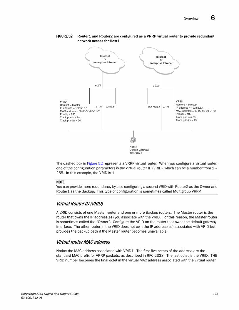
Overview 6DRAFT: BROCADE CONFIDENTIAL
FIGURE 52 Router1 and Router2 are configured as a VRRP virtual router to provide redundant network access for Host1
The dashed box in Figure 52 represents a VRRP virtual router. When you configure a virtual router, one of the configuration parameters is the virtual router ID (VRID), which can be a number from 1 – 255. In this example, the VRID is 1.
NOTEYou can provide more redundancy by also configuring a second VRID with Router2 as the Owner and Router1 as the Backup. This type of configuration is sometimes called Multigroup VRRP.
Virtual Router ID (VRID)
A VRID consists of one Master router and one or more Backup routers. The Master router is the router that owns the IP address(es) you associate with the VRID. For this reason, the Master router is sometimes called the “Owner”. Configure the VRID on the router that owns the default gateway interface. The other router in the VRID does not own the IP address(es) associated with VRID but provides the backup path if the Master router becomes unavailable.
Virtual router MAC address
Notice the MAC address associated with VRID1. The first five octets of the address are the standard MAC prefix for VRRP packets, as described in RFC 2338. The last octet is the VRID. THE VRID number becomes the final octet in the virtual MAC address associated with the virtual router.
Internetor
enterprise Intranet
Internetor
enterprise Intranet
Host1Default Gateway192.53.5.1
192.53.5.1e 1/6 e 1/5192.53.5.3
e 3/2e 2/4
VRID1Router1 = MasterIP address = 192.53.5.1MAC address = 00-00-5E-00-01-01Priority = 255Track port = e 2/4Track priority = 20
VRID1Router2 = BackupIP address = 192.53.5.1MAC address = 00-00-5E-00-01-01Priority = 100Track port = e 3/2Track priority = 19
ServerIron ADX Switch and Router Guide 17553-1001742-01
Overview6DRAFT: BROCADE CONFIDENTIAL
When you configure a VRID, the software automatically assigns its MAC address. When a VRID becomes active, the Master router broadcasts a gratuitous ARP request containing the virtual router’s MAC address for each IP address associated with the virtual router. In Figure 52, Router1 sends a gratuitous ARP with MAC address 00-00-5e-00-01-01 and IP address 192.53.5.1. Hosts use the virtual router’s MAC address in routed traffic they send to their default IP gateway (in this example, 192.53.5.1).
Virtual router IP address
VRRP does not use virtual IP addresses. Thus, there is no virtual IP address associated with a virtual router. Instead, you associate the virtual router with one or more real interface IP addresses configured on the router that owns the real IP address(es). In Figure 52, the virtual router with VRID1 is associated with real IP address 192.53.5.1, which is configured on interface e1/6 on Router1. VRIDs are interface-level parameters, not system-level parameters, so the IP address you associate with the VRID must already be a real IP address configured on the Owner’s interface.
When you configure the Backup router for the VRID, specify the same IP address as the one you specify on the Owner. This is the IP address used by the host as its default gateway. The IP address cannot also exist on the Backup router. The interface on which you configure the VRID on the Backup router must have an IP address in the same subnet.
NOTEIf you delete a real IP address used by a VRRP entry, the VRRP entry also is deleted automatically.
NOTEWhen a Backup takes over forwarding responsibilities from a failed Master router, the Backup forwards traffic addressed to the VRID MAC address, which the host believes is the MAC address of the router interface for its default gateway. However, the Backup cannot reply to IP pings sent to the IP address(es) associated with the VRID. Because the IP address(es) are owned by the Owner, if the Owner is unavailable, the IP addresses are unavailable as packet destinations.
Master negotiation
The routers within a VRID use the VRRP priority values associated with each router to determine which router becomes the Master. When you configure the VRID on a router interface, you specify whether the router is the Owner of the IP address(es) you plan to associate with the VRID or a Backup. If you indicate that the router is the Owner of the IP address(es), the software automatically sets the router’s VRRP priority for the VRID to 255, the highest VRRP priority. The router with the highest priority becomes the Master.
Backup routers can have a priority from 3 – 254, which you assign when you configure the VRID on the Backup router’s interfaces. The default VRRP priority for Backup routers is 100.
Because the router that owns the IP addresses associated with the VRID always has the highest priority, when all the routers in the virtual router are operating normally, the negotiation process results in the Owner of the VRID’s IP address(es) becoming the Master router. Thus, the VRRP negotiation results in the normal case, in which the hosts’ path to the default route is to the router that owns the interface for that route.
176 ServerIron ADX Switch and Router Guide53-1001742-01

Overview 6DRAFT: BROCADE CONFIDENTIAL
Hello messages
VRRP routers use Hello messages for negotiation to determine the Master router. VRRP routers send Hello messages to IP Multicast address 224.0.0.18. The frequency with which the Master sends Hello messages is the Hello Interval. Only the Master sends Hello messages. However, a Backup uses the Hello interval you configure for the Backup if it becomes the Master.
The Backup routers wait for a period of time called the Dead Interval for a Hello message from the Master. If a Backup router does not receive a Hello message by the time the dead interval expires, the Backup router assumes that the Master router is dead and negotiates with the other Backups to select a new Master router. The Backup router with the highest priority becomes the new Master.
If the Owner becomes unavailable, but then comes back online, the Owner again becomes the Master router. The Owner becomes the Master router again because it has the highest priority. The Owner always becomes the Master again when the Owner comes back online.
NOTEIf you configure a track port on the Owner and the track port is down, the Owner’s priority is changed to the track priority. In this case, the Owner does not have a higher priority than the Backup that is acting as Master and the Owner therefore does not resume its position as Master. For more information about track ports, refer to “Track ports and track priority” on page 177.
By default, if a Backup is acting as the Master, and the Master is still unavailable, another Backup can “preempt” the Backup that is acting as the Master. This can occur if the new Backup has a higher priority than the Backup who is acting as Master. You can disable this behavior if you want. When you disable preemption, a Backup router that has a higher priority than the router who is currently acting as Master does not preempt the new Master by initiating a new Master negotiation. Refer to “Backup preempt” on page 193.
NOTERegardless of the setting for the preempt parameter, the Owner always becomes the Master again when it comes back online.
Track ports and track priority
The Brocade implementation of VRRP enhances the protocol by giving a VRRP router the capability to monitor the state of the interfaces on the other end of the route path through the router. For example, in Figure 52 on page 175, interface e1/6 on Router1 owns the IP address to which Host1 directs route traffic on its default gateway. The exit path for this traffic is through Router1’s e2/4 interface.
Suppose interface e2/4 goes down. Even if interface e1/6 is still up, Host1 is nonetheless cut off from other networks. In conventional VRRP, Router1 would continue to be the Master router despite the unavailability of the exit interface for the path the router is supporting. However, if you configure interface e1/6 to track the state of interface e2/4, if e2/4 goes down, interface e1/6 responds by changing Router1’s VRRP priority to the value of the track priority. In the configuration shown in Figure 52 on page 175, Router1’s priority changes from 255 to 20. One of the parameters contained in the Hello messages the Master router sends to its Backups is the Master router’s priority. If the track port feature results in a change in the Master router’s priority, the Backup routers quickly become aware of the change and initiate a negotiation for Master router.
ServerIron ADX Switch and Router Guide 17753-1001742-01

Overview6DRAFT: BROCADE CONFIDENTIAL
In Figure 52 on page 175, the track priority results in Router1’s VRRP priority becoming lower than Router2’s VRRP priority. As a result, when Router2 learns that it now has a higher priority than Router1, Router2 initiates negotiation for Master router and becomes the new Master router, thus providing an open path for Host1’s traffic. To take advantage of the track port feature, make sure the track priorities are always lower than the VRRP priorities. The default track priority for the router that owns the VRID IP address(es) is 2. The default track priority for Backup routers is 1. If you change the track port priorities, make sure you assign a higher track priority to the Owner of the IP address(es) than the track priority you assign on the Backup routers.
Suppression of RIP advertisements for backed up interfaces
The Brocade implementation also enhances VRRP by allowing you to configure the protocol to suppress RIP advertisements for the backed up paths from Backup routers. Normally, a VRRP Backup router includes route information for the interface it is backing up in RIP advertisements. As a result, other routers receive multiple paths for the interface and might sometimes unsuccessfully use the path to the Backup rather than the path to the Master. If you enable the Brocade implementation of VRRP to suppress the VRRP Backup routers from advertising the backed up interface in RIP, other routers learn only the path to the Master router for the backed up interface.
Authentication
The Brocade implementation of VRRP can use simple passwords to authenticate VRRP packets. The VRRP authentication type is not a parameter specific to the VRID. Instead, VRRP uses the authentication type associated with the interfaces on which you define the VRID. For example, if you configure your router interfaces to use a simple password to authenticate traffic, VRRP uses the same simple password and VRRP packets that do not contain the password are dropped. If your interfaces do not use authentication, neither does VRRP.
NOTEThe MD5 authentication type is not supported for VRRP.
Independent operation of VRRP alongside RIP, and OSPF
VRRP operation is independent of the RIP and OSPF protocols. Their operation is unaffected when VRRP is enabled on a RIP or OSPF interface.
Dynamic VRRP configuration
All VRRP global and interface parameters take effect immediately. You do not need to reset the system to place VRRP configuration parameters into effect.
Overview of VRRP-EVRRP-E is similar to VRRP, but differs in the following respects:
• Owners and Backups:
• VRRP has an Owner and one or more Backups for each VRID. The Owner is the router on which the VRID's IP address is also configured as a real address. All the other routers supporting the VRID are Backups.
178 ServerIron ADX Switch and Router Guide53-1001742-01
Overview 6DRAFT: BROCADE CONFIDENTIAL
• VRRP-E does not use Owners. All routers are Backups for a given VRID. The router with the highest priority becomes Master. If there is a tie for highest priority, the router with the highest IP address becomes Master. The elected Master owns the virtual IP address and answers ping and ARP requests and so on.
• VRID's IP address:
• VRRP requires that the VRID also be a real IP address configured on the VRID's interface on the Owner.
• VRRP-E requires only that the VRID be in the same subnet as an interface configured on the VRID's interface. In fact, VRRP-E does not allow you to specify a real IP address configured on the interface as the VRID IP address.
• VRID's MAC Address:
• VRRP source MAC is a virtual MAC address defined as 00-00-5E-00-01-<vrid>, where <vrid> is the VRID. The Master owns the Virtual MAC address.
• VRRP-E uses the interface’s actual MAC address as the source MAC address. The MAC address is 02-E0-52-<hash-value>-<vrid>, where <hash-value> is a two-octet hashed value for the IP address and <vrid> is the VRID.
• Hello packets:
• VRRP sends Hello messages to IP Multicast address 224.0.0.18.
• VRRP-E uses UDP to send Hello messages in IP multicast messages. The Hello packets use the interface’s actual MAC address and IP address as the source addresses. The destination MAC address is 01-00-5E-00-00-02, and the destination IP address is 224.0.0.2 (the well-known IP multicast address for “all routers”). Both the source and destination UDP port number is 8888. VRRP messages are encapsulated in the data portion of the packet.
• Track ports and track priority:
• VRRP changes the priority of the VRID to the track priority, which typically is lower than the VRID priority and lower than the VRID’s priorities configured on the Backups. For example, if the VRRP interface’s priority is 100 and a tracked interface with track priority 20 goes down, the software changes the VRRP interface’s priority to 20.
• VRRP-E reduces the priority of a VRRP-E interface by the amount of a tracked interface’s priority if the tracked interface’s link goes down. For example, if the VRRP-E interface’s priority is 200 and a tracked interface with track priority 20 goes down, the software changes the VRRP-E interface’s priority to 180. If another tracked interface goes down, the software reduces the VRID’s priority again, by the amount of the tracked interface’s track priority.
The most important difference is that all VRRP-E routers are Backups. There is no Owner router. VRRP-E overcomes the limitations in standard VRRP by removing the Owner.
Figure 53 shows an example of a VRRP-E configuration.
ServerIron ADX Switch and Router Guide 17953-1001742-01
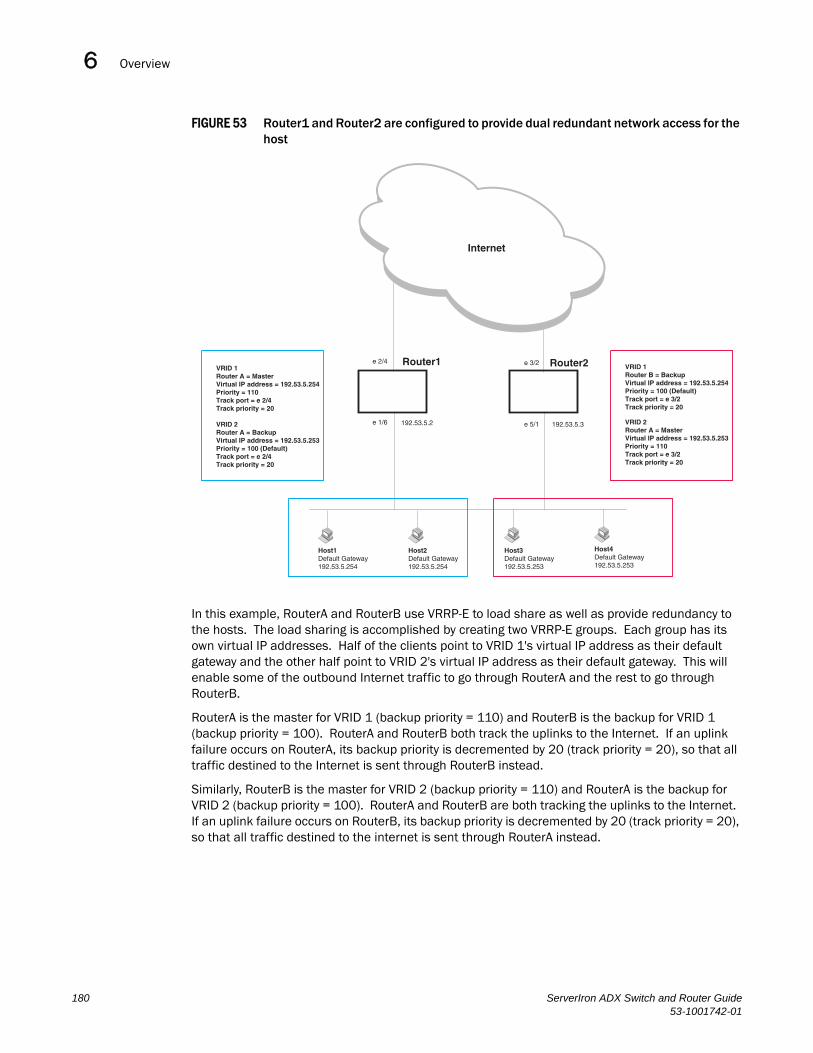
Overview6DRAFT: BROCADE CONFIDENTIAL
FIGURE 53 Router1 and Router2 are configured to provide dual redundant network access for the host
In this example, RouterA and RouterB use VRRP-E to load share as well as provide redundancy to the hosts. The load sharing is accomplished by creating two VRRP-E groups. Each group has its own virtual IP addresses. Half of the clients point to VRID 1's virtual IP address as their default gateway and the other half point to VRID 2's virtual IP address as their default gateway. This will enable some of the outbound Internet traffic to go through RouterA and the rest to go through RouterB.
RouterA is the master for VRID 1 (backup priority = 110) and RouterB is the backup for VRID 1 (backup priority = 100). RouterA and RouterB both track the uplinks to the Internet. If an uplink failure occurs on RouterA, its backup priority is decremented by 20 (track priority = 20), so that all traffic destined to the Internet is sent through RouterB instead.
Similarly, RouterB is the master for VRID 2 (backup priority = 110) and RouterA is the backup for VRID 2 (backup priority = 100). RouterA and RouterB are both tracking the uplinks to the Internet. If an uplink failure occurs on RouterB, its backup priority is decremented by 20 (track priority = 20), so that all traffic destined to the internet is sent through RouterA instead.
Internet
Router1 Router2e 2/4
e 1/6 192.53.5.2 192.53.5.3e 5/1
e 3/2
Host1Default Gateway192.53.5.254
Host2Default Gateway192.53.5.254
Host3Default Gateway192.53.5.253
Host4Default Gateway192.53.5.253
VRID 1Router A = MasterVirtual IP address = 192.53.5.254Priority = 110Track port = e 2/4Track priority = 20
VRID 2Router A = BackupVirtual IP address = 192.53.5.253Priority = 100 (Default)Track port = e 2/4Track priority = 20
VRID 1Router B = BackupVirtual IP address = 192.53.5.254Priority = 100 (Default)Track port = e 3/2Track priority = 20
VRID 2Router A = MasterVirtual IP address = 192.53.5.253Priority = 110Track port = e 3/2Track priority = 20
180 ServerIron ADX Switch and Router Guide53-1001742-01
Comparison of VRRP and VRRP-E 6DRAFT: BROCADE CONFIDENTIAL
Comparison of VRRP and VRRP-EThis section compares Brocade’s router redundancy protocols.
VRRPVRRP is a standards-based protocol, described in RFC 2338. The Brocade implementation of VRRP contains the features in RFC 2338. The Brocade implementation also provides the following additional features:
• Track ports – A Brocade feature that enables you to diagnose the health of all the Layer 3 Switch’s ports used by the backed-up VRID, instead of only the port connected to the client subnet. Refer to “Track ports and track priority” on page 177.
• Suppression of RIP advertisements on Backup routes for the backed up interface – You can enable the Layer 3 Switches to advertise only the path to the Master router for the backed up interface. Normally, a VRRP Backup router includes route information for the interface it is backing up in RIP advertisements.
Brocade Layer 3 Switches configured for VRRP can interoperate with third-party routers using VRRP.
VRRP-EVRRP-E is a Brocade protocol that provides the benefits of VRRP without the limitations. VRRP-E is unlike VRRP in the following ways:
• There is no “Owner” router. You do not need to use an IP address configured on one of the Layer 3 Switches as the virtual router ID (VRID), which is the address you are backing up for redundancy. The VRID is independent of the IP interfaces configured in the Layer 3 Switches. As a result, the protocol does not have an “Owner” as VRRP does.
• There is no restriction on which router can be the default master router. In VRRP, the “Owner” (the Layer 3 Switch on which the IP interface that is used for the VRID is configured) must be the default Master.
Brocade Layer 3 Switches configured for VRRP-E can interoperate only with other Brocade Layer 3 Switches.
Architectural differencesThe protocols have the following architectural differences:
Management protocol
• VRRP – VRRP routers send VRRP Hello and Hello messages to IP Multicast address 224.0.0.18.
• VRRP-E – VRRP-E sends messages to destination MAC address 01-00-5E-00-00-02 and destination IP address 224.0.0.2 (the standard IP multicast address for “all routers”).
ServerIron ADX Switch and Router Guide 18153-1001742-01
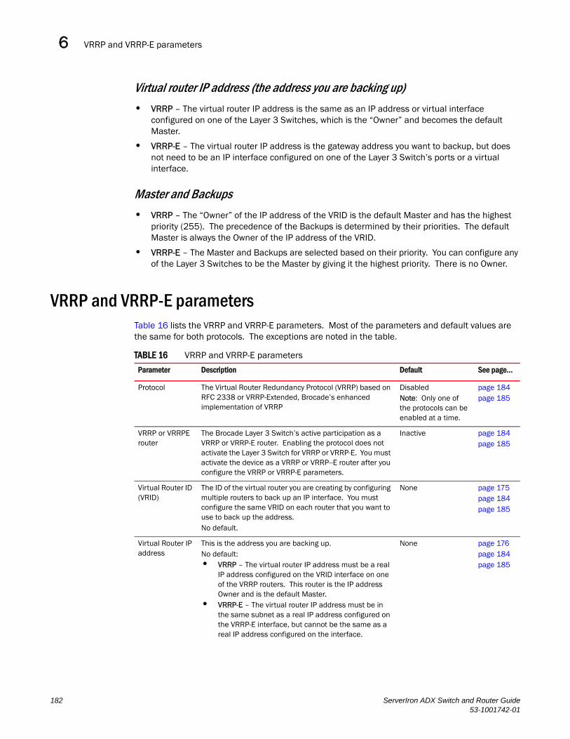
VRRP and VRRP-E parameters6DRAFT: BROCADE CONFIDENTIAL
Virtual router IP address (the address you are backing up)
• VRRP – The virtual router IP address is the same as an IP address or virtual interface configured on one of the Layer 3 Switches, which is the “Owner” and becomes the default Master.
• VRRP-E – The virtual router IP address is the gateway address you want to backup, but does not need to be an IP interface configured on one of the Layer 3 Switch’s ports or a virtual interface.
Master and Backups
• VRRP – The “Owner” of the IP address of the VRID is the default Master and has the highest priority (255). The precedence of the Backups is determined by their priorities. The default Master is always the Owner of the IP address of the VRID.
• VRRP-E – The Master and Backups are selected based on their priority. You can configure any of the Layer 3 Switches to be the Master by giving it the highest priority. There is no Owner.
VRRP and VRRP-E parametersTable 16 lists the VRRP and VRRP-E parameters. Most of the parameters and default values are the same for both protocols. The exceptions are noted in the table.
TABLE 16 VRRP and VRRP-E parameters
Parameter Description Default See page...
Protocol The Virtual Router Redundancy Protocol (VRRP) based on RFC 2338 or VRRP-Extended, Brocade’s enhanced implementation of VRRP
DisabledNote: Only one of the protocols can be enabled at a time.
page 184page 185
VRRP or VRRPE router
The Brocade Layer 3 Switch’s active participation as a VRRP or VRRP-E router. Enabling the protocol does not activate the Layer 3 Switch for VRRP or VRRP-E. You must activate the device as a VRRP or VRRP--E router after you configure the VRRP or VRRP-E parameters.
Inactive page 184page 185
Virtual Router ID (VRID)
The ID of the virtual router you are creating by configuring multiple routers to back up an IP interface. You must configure the same VRID on each router that you want to use to back up the address.No default.
None page 175page 184page 185
Virtual Router IP address
This is the address you are backing up.No default:• VRRP – The virtual router IP address must be a real
IP address configured on the VRID interface on one of the VRRP routers. This router is the IP address Owner and is the default Master.
• VRRP-E – The virtual router IP address must be in the same subnet as a real IP address configured on the VRRP-E interface, but cannot be the same as a real IP address configured on the interface.
None page 176page 184page 185
182 ServerIron ADX Switch and Router Guide53-1001742-01

VRRP and VRRP-E parameters 6DRAFT: BROCADE CONFIDENTIAL
VRID MAC address
The source MAC address in VRRP or VRRP-E packets sent from the VRID interface, and the destination for packets sent to the VRID:• VRRP – A virtual MAC address defined as
00-00-5e-00-01-<vrid>. The Master owns the Virtual MAC address.
• VRRP-E – A virtual MAC address defined as 02-E0-52-<hash-value>-<vrid>, where <hash-value> is a two-octet hashed value for the IP address and <vrid> is the VRID.
Not configurable page 175
Authentication type
The type of authentication the VRRP or VRRP-E routers use to validate VRRP or VRRP-E packets. The authentication type must match the authentication type the VRID’s port uses with other routing protocols such as OSPF:• No authentication – The interfaces do not use
authentication. This is the VRRP default.• Simple – The interface uses a simple text-string as a
password in packets sent on the interface. If the interface uses simple password authentication, the VRID configured on the interface must use the same authentication type and the same password.
NOTE: MD5 is not supported by VRRP or VRRP-E.
No authentication page 178page 187
Router type Whether the router is an Owner or a Backup:• Owner (VRRP only) – The router on which the real IP
address used by the VRID is configured.• Backup – Routers that can provide routing services
for the VRID but do not have a real IP address matching the VRID.
VRRP – The Owner is always the router that has the real IP address used by the VRID. All other routers for the VRID are Backups.VRRPE – All routers for the VRID are Backups.
page 187
Backup priority A numeric value that determines a Backup’s preferability for becoming the Master for the VRID. During negotiation, the router with the highest priority becomes the Master:• VRRP – The Owner has the highest priority (255);
other routers can have a priority from 3 – 254.• VRRP-E – All routers are Backups and have the
same priority by default.If two or more Backups are tied with the highest priority, the Backup interface with the highest IP address becomes the Master for the VRID.
VRRP – 255 for the Owner; 100 for each BackupVRRPE – 100 for all Backups
page 187
Suppression of RIP advertisements
A router that is running RIP normally advertises routes to a backed up VRID even when the router is not currently the active router for the VRID. Suppression of these advertisements helps ensure that other routers do not receive invalid route paths for the VRID.
Disabled page 189
Hello interval The number of seconds between Hello messages from the Master to the Backups for a given VRID. The interval can from 1 – 84 seconds.
One second page 177page 189
TABLE 16 VRRP and VRRP-E parameters (Continued)
Parameter Description Default See page...
ServerIron ADX Switch and Router Guide 18353-1001742-01

Configuring basic VRRP parameters6DRAFT: BROCADE CONFIDENTIAL
Configuring basic VRRP parametersTo implement a simple VRRP configuration using all the default values, enter commands such as the following.
Configuring the ownerRouter1(config)# router vrrpRouter1(config)# inter e 1/6Router1(config-if-1/6)# ip address 192.53.5.1Router1(config-if-1/6)# ip vrrp vrid 1Router1(config-if-1/6-vrid-1)# ownerRouter1(config-if-1/6-vrid-1)# ip-address 192.53.5.1Router1(config-if-1/6-vrid-1)# activate
Dead interval The number of seconds a Backup waits for a Hello message from the Master for the VRID before determining that the Master is no longer active. If the Master does not send a Hello message before the dead interval expires, the Backups negotiate (compare priorities) to select a new Master for the VRID.
Three times the Hello Interval plus one-half second
page 177page 189
Backup Hello interval
The number of seconds between Hello messages from a Backup to the Master. The message interval can be from 60 – 3600 seconds.You must enable the Backup to send the messages. The messages are disabled by default on Backups. The current Master (whether the VRRP Owner or a Backup) sends Hello messages by default.
Disabled60 seconds when enabled
page 177page 190
Track port Another Layer 3 Switch port or virtual interface whose link status is tracked by the VRID’s interface.If the link for a tracked interface goes down, the VRRP or VRRP-E priority of the VRID interface is changed, causing the devices to renegotiate for Master.
None page 177page 190
Track priority A VRRP or VRRP-E priority value assigned to the tracked port(s). If a tracked port’s link goes down, the VRID port’s VRRP or VRRP-E priority changes:• VRRP – The priority changes to the value of the
tracked port’s priority.• VRRP-E – The VRID port’s priority is reduced by the
amount of the tracked port’s priority.
VRRP – 2VRRPE – 5
page 177page 193
Backup preempt mode
Prevents a Backup with a higher VRRP priority from taking control of the VRID from another Backup that has a lower priority but has already assumed control of the VRID.
Enabled page 193
TABLE 16 VRRP and VRRP-E parameters (Continued)
Parameter Description Default See page...
184 ServerIron ADX Switch and Router Guide53-1001742-01

Configuring basic VRRP-E parameters 6DRAFT: BROCADE CONFIDENTIAL
Configuring a backupRouter2(config)# router vrrpRouter2(config)# inter e 1/5Router2(config-if-1/5)# ip address 192.53.5.3Router2(config-if-1/5)# ip vrrp vrid 1Router2(config-if-1/5-vrid-1)# backupRouter2(config-if-1/5-vrid-1)# ip-address 192.53.5.1Router2(config-if-1/5-vrid-1)# activate
Configuration rules for VRRPThe rules to be followed are given below:
• The interfaces of all routers in a VRID must be in the same IP subnet.
• The IP address(es) associated with the VRID must already be configured on the router that will be the Owner router.
• An IP address(es) associated with the VRID must be on only one router.
• The Hello interval must be set to the same value on both the Owner and Backup(s) for the VRID.
• The Dead interval must be set to the same value on both the Owner and Backup(s) for the VRID.
• The track priority on a router must be lower than the router’s VRRP priority. Also, the track priority on the Owner must be higher than the track priority on the Backup(s).
Configuring basic VRRP-E parametersTo implement a simple VRRP-E configuration using all the default values, enter commands such as the following on each Layer 3 Switch.
Router2(config)# router vrrp-extendedRouter2(config)# inter e 1/5Router2(config-if-1/5)# ip address 192.53.5.3Router2(config-if-1/5)# ip vrrp-extended vrid 1Router2(config-if-1/5-vrid-1)# backupRouter2(config-if-1/5-vrid-1)# ip-address 192.53.5.254Router2(config-if-1/5-vrid-1)# activate
NOTEYou also can use the enable command to activate the configuration. This command does the same thing as the activate command.
Configuration rules for VRRP-EThe rules are as follows:
• The interfaces of all routers in a VRID must be in the same IP subnet.
• The IP address(es) associated with the VRID cannot be configured on any of the Layer 3 Switches.
• The Hello interval must be set to the same value on all the Layer 3 Switches.
ServerIron ADX Switch and Router Guide 18553-1001742-01

Note regarding disabling VRRP or VRRP-E6DRAFT: BROCADE CONFIDENTIAL
• The Dead interval must be set to the same value on all the Layer 3 Switches.
• The track priority for a VRID must be lower than the VRRP-E priority.
Note regarding disabling VRRP or VRRP-EIf you disable VRRP or VRRP-E, the Layer 3 Switch removes all the configuration information for the disabled protocol from the running-config. Moreover, when you save the configuration to the startup-config file after disabling one of these protocols, all the configuration information for the disabled protocol is removed from the startup-config file.
The CLI displays a warning message such as the following.
ServerIronADX(config-vrrp-router)# no router vrrprouter vrrp mode now disabled. All vrrp config data will be lost when writing to flash!
If you have disabled the protocol but have not yet saved the configuration to the startup-config file and reloaded the software, you can restore the configuration information by re-entering the command to enable the protocol (ex: router vrrp). If you have already saved the configuration to the startup-config file and reloaded the software, the information is gone.
If you are testing a VRRP or VRRP-E configuration and are likely to disable and re-enable the protocol, you might want to make a backup copy of the startup-config file containing the protocol’s configuration information. This way, if you remove the configuration information by saving the configuration after disabling the protocol, you can restore the configuration by copying the backup copy of the startup-config file onto the flash memory.
Configuring additional VRRP and VRRP-E parametersYou can modify the following VRRP and VRRP-E parameters on an individual VRID basis. These parameters apply to both protocols:
• Authentication type (if the interfaces on which you configure the VRID use authentication)
• Router type (Owner or Backup)
NOTEFor VRRP, change the router type only if you have moved the real IP address from one router to another or you accidentally configured the IP address Owner as a Backup.
For VRRPE, the router type is always Backup. You cannot change the type to Owner.
• Backup priority
• Suppression of RIP advertisements on Backup routes for the backed up interface
• Hello interval
• Dead interval
• Backup Hello messages and message timer (Backup advertisement)
• Track port
• Track priority
• Backup preempt mode
186 ServerIron ADX Switch and Router Guide53-1001742-01
Configuring additional VRRP and VRRP-E parameters 6DRAFT: BROCADE CONFIDENTIAL
Refer to “VRRP and VRRP-E parameters” on page 182 for a summary of the parameters and their defaults.
Authentication type
If the interfaces on which you configure the VRID use authentication, the VRRP or VRRP-E packets on those interfaces also must use the same authentication. Brocade’s implementation of VRRP and VRRP-E supports the following authentication types:
• No authentication – The interfaces do not use authentication. This is the default for VRRP and VRRP-E.
• Simple – The interfaces use a simple text-string as a password in packets sent on the interface. If the interfaces use simple password authentication, the VRID configured on the interfaces must use the same authentication type and the same password.
To configure the VRID interface on Router1 for simple-password authentication using the password “ourpword”, enter the following commands.
Configuring Router 1Router1(config)# inter e 1/6Router1(config-if-1/6)# ip vrrp auth-type simple-text-auth ourpword
Configuring Router 2Router2(config)# inter e 1/5Router2(config-if-1/5)# ip vrrp auth-type simple-text-auth ourpword
VRRP syntaxSyntax: ip vrrp auth-type no-auth | simple-text-auth <auth-data>
The auth-type no-auth parameter indicates that the VRID and the interface it is configured on do not use authentication.
The auth-type simple-text-auth <auth-data> parameter indicates that the VRID and the interface it is configured on use a simple text password for authentication. The <auth-data> parameter is the password. If you use this parameter, make sure all interfaces on all the routers supporting this VRID are configured for simple password authen-tication and use the same password.
VRRP-E syntaxSyntax: ip vrrp-extended auth-type no-auth | simple-text-auth <auth-data>
The parameter values are the same as for VRRP.
Router type
A VRRP interface is either an Owner or a Backup for a given VRID. By default, the Owner becomes the Master following the negotiation. A Backup becomes the Master only if the Master becomes unavailable.
A VRRP-E interface is always a Backup for its VRID. The Backup with the highest VRRP priority becomes the Master.
This section describes how to specify the interface type, how to change the type for VRRP, and how to set or change the interface’s VRRP or VRRPE priority and track priority for the VRID.
ServerIron ADX Switch and Router Guide 18753-1001742-01

Configuring additional VRRP and VRRP-E parameters6DRAFT: BROCADE CONFIDENTIAL
NOTEYou can force a VRRP master router to abdicate (give away control) of the VRID to a Backup by temporarily changing the Master’s VRRP priority to a value less than the Backup’s. Refer to “Forcing a master router to abdicate to a standby router” on page 194.
NOTEThe type Owner is not applicable to VRRP-E.
NOTEThe IP address(es) you associate with the Owner must be a real IP address (or addresses) on the interface on which you configure the VRID.
When you configure a Backup router, the router interface on which you are configuring the VRID must have a real IP address that is in the same subnet as the address associated with the VRID by the Owner. However, the address cannot be the same.
To configure Router1 as a VRRP VRID’s Owner, enter the following commands.
Router1(config)# inter e 1/6Router1(config-if-1/6)# ip vrrp vrid 1Router1(config-if-1/6-vrid-1)# owner
To configure Router2 as a VRRP Backup for the same VRID, enter the following commands.
Router2(config)# inter e 1/5Router2(config-if-1/5)# ip vrrp vrid 1Router2(config-if-1/5-vrid-1)# backupRouter2(config-if-1/5-vrid-1)# advertise backup
To configure a VRRP-E interface as a Backup for a VRID and set its VRRP-E priority and track priority, enter commands such as the following.
ServerIronADX(config)# inter e 1/1ServerIronADX(config-if-1/1)# ip vrrp-extended vrid 1ServerIronADX(config-if-1/1-vrid-1)# backup priority 50 track-priority 10ServerIronADX(config-if-1/1-vrid-1)# advertise backup
VRRP syntaxSyntax: owner [track-priority <value>]
The track-priority <value> parameter changes the track-port priority for this interface and VRID from the default (2) to a value from 1 – 254.
Syntax: backup [priority <value>] [track-priority <value>]
The priority <value> parameter specifies the VRRP priority for this interface and VRID. You can specify a value from 3 – 254. The default is 100.
The track-priority <value> parameter is the same as above.
NOTE-You cannot set the priority of a VRRP Owner. The Owner’s priority is always 255.
VRRP-E syntaxSyntax: backup [priority <value>] [track-priority <value>]
188 ServerIron ADX Switch and Router Guide53-1001742-01

Configuring additional VRRP and VRRP-E parameters 6DRAFT: BROCADE CONFIDENTIAL
The software requires you to identify a VRRP-E interface as a Backup for its VRID before you can activate the interface for the VRID. However, after you configure the VRID, you can use this command to change its priority or track priority. The parameter values are the same as for VRRP.
Suppression of RIP advertisements on Backup routers for the backed up interface
Normally, a VRRP or VRRP-E Backup includes route information for the virtual IP address (the backed up interface) in RIP advertisements. As a result, other routers receive multiple paths for the backed up interface and might sometimes unsuccessfully use the path to the Backup rather than the path to the Master.
You can prevent the Backups from advertising route information for the backed up interface by enabling suppression of the advertisements.
To suppress RIP advertisements for the backed up interface in Router2, enter the following commands.
Router2(config)# router ripRouter2(config-rip-router)# use-vrrp-path
Syntax: use-vrrp-path
The syntax is the same for VRRP and VRRP-E.
Hello interval
The Master periodically sends Hello messages to the Backups. The Backups use the Hello messages as verification that the Master is still on-line. If the Backup routers stop receiving the Hello messages for the period of time specified by the Dead interval, the Backup routers determine that the Master router is dead. At this point, the Backup router with the highest priority becomes the new Master router. The Hello interval can be from 1 – 84 seconds. The default is 1 second.
NOTEThe default Dead interval is three times the Hello Interval plus one-half second. Generally, if you change the Hello interval, you also should change the Dead interval on the Backup routers.
To change the Hello interval on the Master to 10 seconds, enter the following commands.
Router1(config)# inter e 1/6Router1(config-if-1/6)# ip vrrp vrid 1Router1(config-if-1/6-vrid-1)# hello-interval 10
Syntax: hello-interval <value>
The syntax is the same for VRRP and VRRP-E.
Dead interval
The Dead interval is the number of seconds a Backup waits for a Hello message from the Master before determining that the Master is dead. When Backups determine that the Master is dead, the Backup with the highest priority becomes the new Master. The Dead interval can be from 1 – 84 seconds. The default is 3.5 seconds. This is three times the default Hello interval (1 second) plus one-half second added by the router software. The software automatically adds one-half second to the Dead interval value you enter.
To change the Dead interval on a Backup to 30 seconds, enter the following commands.
ServerIron ADX Switch and Router Guide 18953-1001742-01

Configuring additional VRRP and VRRP-E parameters6DRAFT: BROCADE CONFIDENTIAL
Router2(config)# inter e 1/5Router2(config-if-1/5)# ip vrrp vrid 1Router2(config-if-1/5-vrid-1)# dead-interval 30
Syntax: dead-interval <value>
The syntax is the same for VRRP and VRRP-E.
Backup Hello message state and interval
By default, Backup do not send Hello messages to advertise themselves to the Master. You can enable these messages if desired and also change the message interval.
To enable a Backup to send Hello messages to the Master, enter commands such as the following.
ServerIronADX(config)# router vrrpServerIronADX(config)# inter e 1/6ServerIronADX(config-if-1/6)# ip vrrp vrid 1ServerIronADX(config-if-1/6-vrid-1)# advertise backup
Syntax: [no] advertise backup
When you enable a Backup to send Hello messages, the Backup sends a Hello messages to the Master every 60 seconds by default. You can change the interval to be up to 3600 seconds. To do so, enter commands such as the following.
ServerIronADX(config)# router vrrpServerIronADX(config)# inter e 1/6ServerIronADX(config-if-1/6)# ip vrrp vrid 1ServerIronADX(config-if-1/6-vrid-1)# backup-hello-interval 180
Syntax: [no] backup-hello-interval <num>
The <num> parameter specifies the message interval and can be from 60 – 3600 seconds. The default is 60 seconds.
The syntax is the same for VRRP and VRRP-E.
Track port
You can configure the VRID on one interface to track the link state of another interface on the Layer 3 Switch. This capability is quite useful for tracking the state of the exit interface for the path for which the VRID is providing redundancy. Refer to “Track ports and track priority” on page 177.
To configure 1/6 on Router1 to track interface 2/4, enter the following commands.
ServerIronADX(config)# inter e 1/6ServerIronADX(config-if-1/6)# ip vrrp vrid 1 ServerIronADX(config-if-1/6-vrid-1)# track-port e 2/4
Syntax: track-port ethernet <portnum> | ve <num>
The syntax is the same for VRRP and VRRP-E.
190 ServerIron ADX Switch and Router Guide53-1001742-01

Configuring additional VRRP and VRRP-E parameters 6DRAFT: BROCADE CONFIDENTIAL
Track trunk port with VRRP-E
The ServerIron ADX allows you to configure trunk ports to provide the higher bandwidth required by many application switching network designs. If, however, an individual port within a trunk fails the expected throughput will fall but failover in a VRRP-E track port configuration will not occur unless all of the ports in the trunk fail.
The Track Trunk Port with VRRP-E feature allows the ServerIron ADX to track the failure of individual ports within a trunk. When a tracked port within a trunk fails, the VRID priority value is changed as described in the following.
• If all ports in the trunk are up, the VRID priority value is unchanged.
• If none of the ports in the trunk are up, the Track Priority is subtracted from the backup priority to determine the current VRID priority value.
• If any of the ports in the trunk fail, the following formula is used.
• A new Track Priority value is determined by the following formula: track priority x ( number of configured ports in trunk - the number of active ports in trunk) ÷ number of configured ports in trunk
• The new Track Priority value is subtracted from the backup priority value to determine the current VRID priority
Configuration ConsiderationsThe following must be considered when configureing the Track Trunk port feature:
• This feature only applies to VRRP-E
• Only ports that are members of a static trunk or are LACP enabled can be configured as track trunk ports
• If a port that is not a member of a trunk group or LACP is configured as a track trunk port, it will behave like a track port
• If different ports with the same trunk group are configured as track port and track trunk port, they will all behave as if configured as track trunk ports
• Before removing a static trunk or LACP confiiguration, a port should be removed from the track trunk port list.
• Co-existance of track-port and track-trunk-port within the same trunk should be avoided.
• Co-existance of track-trunk-port and track-port ve with in the same trunk should be avoided.
• If you are using track-trunk-port, it is preferable to configure all the ports with in the trunk as track-trunk-ports
Example
This example provides the VRRP-E configuration described in the following:
• A trunk is created with Ethernet ports 4/9 and 4/10
• A VRRP-E is created with the VRID value of 1
• For VRID 1, the backup priority is 200 and the track priority is 100
• Both ports in the trunk are are configured as Track Trunk ports
If one of the ports in this configuration go down, the new track priority will be determined as shown in the following equation.
ServerIron ADX Switch and Router Guide 19153-1001742-01
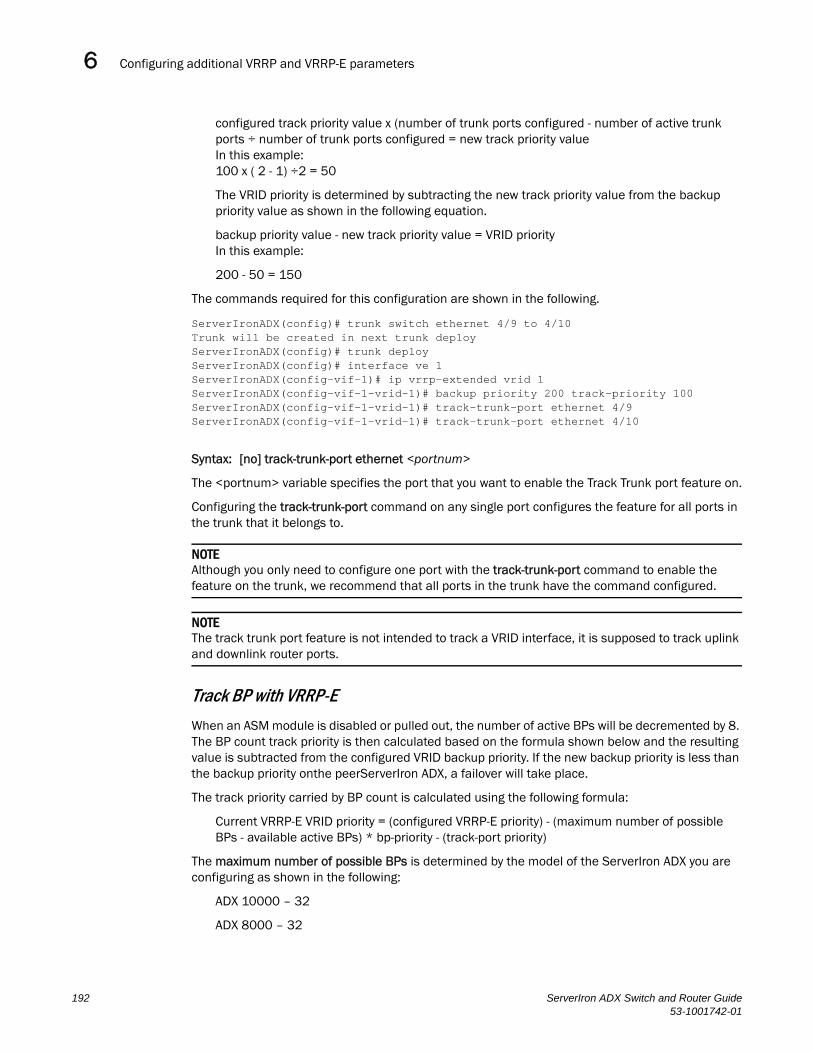
Configuring additional VRRP and VRRP-E parameters6DRAFT: BROCADE CONFIDENTIAL
configured track priority value x (number of trunk ports configured - number of active trunk ports ÷ number of trunk ports configured = new track priority valueIn this example:100 x ( 2 - 1) ÷2 = 50
The VRID priority is determined by subtracting the new track priority value from the backup priority value as shown in the following equation.
backup priority value - new track priority value = VRID priorityIn this example:
200 - 50 = 150
The commands required for this configuration are shown in the following.
ServerIronADX(config)# trunk switch ethernet 4/9 to 4/10Trunk will be created in next trunk deployServerIronADX(config)# trunk deployServerIronADX(config)# interface ve 1ServerIronADX(config-vif-1)# ip vrrp-extended vrid 1 ServerIronADX(config-vif-1-vrid-1)# backup priority 200 track-priority 100ServerIronADX(config-vif-1-vrid-1)# track-trunk-port ethernet 4/9ServerIronADX(config-vif-1-vrid-1)# track-trunk-port ethernet 4/10
Syntax: [no] track-trunk-port ethernet <portnum>
The <portnum> variable specifies the port that you want to enable the Track Trunk port feature on.
Configuring the track-trunk-port command on any single port configures the feature for all ports in the trunk that it belongs to.
NOTEAlthough you only need to configure one port with the track-trunk-port command to enable the feature on the trunk, we recommend that all ports in the trunk have the command configured.
NOTEThe track trunk port feature is not intended to track a VRID interface, it is supposed to track uplink and downlink router ports.
Track BP with VRRP-E
When an ASM module is disabled or pulled out, the number of active BPs will be decremented by 8. The BP count track priority is then calculated based on the formula shown below and the resulting value is subtracted from the configured VRID backup priority. If the new backup priority is less than the backup priority onthe peerServerIron ADX, a failover will take place.
The track priority carried by BP count is calculated using the following formula:
Current VRRP-E VRID priority = (configured VRRP-E priority) - (maximum number of possible BPs - available active BPs) * bp-priority - (track-port priority)
The maximum number of possible BPs is determined by the model of the ServerIron ADX you are configuring as shown in the following:
ADX 10000 – 32
ADX 8000 – 32
192 ServerIron ADX Switch and Router Guide53-1001742-01

Configuring additional VRRP and VRRP-E parameters 6DRAFT: BROCADE CONFIDENTIAL
ADX 4000 – 16
ADX 1000 – 4
The available active BPs is determined by the number of BPs that are currently avaialable for use on your ServerIron ADX.
The bp-priority is determined by the value set in the track-bp bp-priority command as shown in the following.
ServerIronADX(config)# interface ve 1ServerIronADX(config-vif-1)# ip vrrp-extended vrid 1 ServerIronADX(config-vif-1-vrid-1)# track-bp priority 1
Syntax: [no] track-bp bp-priority <priority-value>
The <priority-value> variable specifies the “bp-priority” value used when calculating the track priority carried by BP count. Acceptable values are 1 - 255.
NOTEBrocade recommends that you assign small value for the <priority-value> variable (less than 5).
Track priority
When you configure a VRID to track the link state of other interfaces, if one of the tracked interface goes down, the software changes the VRRP or VRRP-E priority of the VRID interface.
• For VRRP, the software changes the priority of the VRID to the track priority, which typically is lower than the VRID priority and lower than the VRID’s priorities configured on the Backups. For example, if the VRRP interface’s priority is 100 and a tracked interface with track priority 60 goes down, the software changes the VRRP interface’s priority to 60.
• For VRRP-E, the software reduces the VRID priority by the amount of the priority of the tracked interface that went down. For example, if the VRRPE interface’s priority is 100 and a tracked interface with track priority 60 goes down, the software changes the VRRPE interface’s priority to 40. If another tracked interface goes down, the software reduces the VRID’s priority again, by the amount of the tracked interface’s track priority.
The default track priority for a VRRP Owner is 2. The default track priority for Backups is 1.
You enter the track priority as a parameter with the owner or backup command. Refer to “Track ports and track priority” on page 177.
Syntax: owner [track-priority <value>]
Syntax: backup [priority <value>] [track-priority <value>]
The syntax is the same for VRRP and VRRPE.
Backup preempt
By default, a Backup that has a higher priority than another Backup that has become the Master can preempt the Master, and take over the role of Master. If you want to prevent this behavior, disable preemption.
Preemption applies only to Backups and takes effect only when the Master has failed and a Backup has assumed ownership of the VRID. The feature prevents a Backup with a higher priority from taking over as Master from another Backup that has a lower priority but has already become the Master of the VRID.
ServerIron ADX Switch and Router Guide 19353-1001742-01

Forcing a master router to abdicate to a standby router6DRAFT: BROCADE CONFIDENTIAL
Preemption is especially useful for preventing flapping in situations where there are multiple Backups and a Backup with a lower priority than another Backup has assumed ownership, because the Backup with the higher priority was unavailable when ownership changed.
If you enable the non-preempt mode (thus disabling the preemption feature) on all the Backups, the Backup that becomes the Master following the disappearance of the Master continues to be the Master. The new Master is not preempted.
NOTEIn VRRP, regardless of the setting for the preempt parameter, the Owner always becomes the Master again when it comes back online.
To disable preemption on a Backup, enter commands such as the following.
Router1(config)# inter e 1/6Router1(config-if-1/6)# ip vrrp vrid 1Router1(config-if-1/6-vrid-1)# non-preempt-mode
Syntax: non-preempt-mode
The syntax is the same for VRRP and VRRP-E.
Forcing a master router to abdicate to a standby routerYou can force a VRRP Master to abdicate (give away control) of a VRID to a Backup by temporarily changing the Master’s priority to a value less than the Backup’s.
The VRRP Owner always has priority 255. You can even use this feature to temporarily change the Owner’s priority to a value from 1 – 254.
NOTEWhen you change a VRRP Owner’s priority, the change takes effect only for the current power cycle. The change is not saved to the startup-config file when you save the configuration and is not retained across a reload or reboot. Following a reload or reboot, the VRRP Owner again has priority 255.
To change the Master’s priority, enter commands such as the following.
ServerIronADX(config)# ip int eth 1/6ServerIronADX(config-if-1/6)# ip vrrp vrid 1ServerIronADX(config-if-1/6-vrid-1)# owner priority 99
Syntax: [no] owner priority | track-priority <num>
The <num> parameter specifies the new priority and can be a number from 1 – 254.
When you press Enter, the software changes the priority of the Master to the specified priority. If the new priority is lower than at least one Backup’s priority for the same VRID, the Backup takes over and becomes the new Master until the next software reload or system reset.
To verify the change, enter the following command from any level of the CLI.
ServerIronADX(config-if-1/6-vrid-1)# show ip vrrpTotal number of VRRP routers defined: 1Interface ethernet 1/6auth-type no authenticationVRID 1state backupadministrative-status enabled
194 ServerIron ADX Switch and Router Guide53-1001742-01

Displaying VRRP and VRRP-E information 6DRAFT: BROCADE CONFIDENTIAL
mode ownerpriority 99current priority 99hello-interval 1 secip-address 192.53.5.1backup routers 192.53.5.2
This example shows that even though this Layer 3 Switch is the Owner of the VRID (“mode owner”), the Layer 3 Switch’s priority for the VRID is only 99 and the state is now “backup” instead of “active”. In addition, the administrative status is “enabled”.
To change the Master’s priority back to the default Owner priority 255, enter “no” followed by the command you entered to change the priority. For example, to change the priority of a VRRP Owner back to 255 from 99, enter the following command.
ServerIronADX(config-if-1/6-vrid-1)# no owner priority 99
You cannot set the priority to 255 using the owner priority command.
Displaying VRRP and VRRP-E informationYou can display the following information for VRRP or VRRP-E:
• Summary configuration and status information
• Detailed configuration and status information
• VRRP and VRRP-E Statistics
• CPU utilization statistics
Displaying summary informationTo display summary information for a Layer 3 Switch, enter the following command at any level of the CLI.
Syntax: show ip vrrp brief | ethernet <portnum> | ve <num> | stat
Syntax: show ip vrrp-extended brief | ethernet <portnum> | ve <num> | stat
The brief parameter displays the summary information. If you do not use this parameter, detailed information is displayed instead. Refer to “Displaying detailed information” on page 196.
The ethernet <portnum> parameter specifies an Ethernet port. If you use this parameter, the command displays VRRP or VRRPE information only for the specified port.
ServerIronADX(config-if-e1000-1/6-vrid-1)# show ip vrrp brief
Total number of VRRP routers defined: 1Interface VRID CurPri P State Master addr Backup addr VIP 1/6 1 255 P Init 192.53.5.1 192.53.5.3 192.53.5.1This example is for VRRP. Here is an example for VRRPE:ServerIronADX(config-if-e1000-1/6-vrid-1)# show ip vrrp-extended brief
Total number of VRRP-Extended routers defined: 1Interface VRID CurPri P State Master addr Backup addr VIP 1/6 1 255 P Init 192.53.5.2 192.53.5.3 192.53.5.254
ServerIron ADX Switch and Router Guide 19553-1001742-01

Displaying VRRP and VRRP-E information6DRAFT: BROCADE CONFIDENTIAL
The ve <num> parameter specifies a virtual interface. If you use this parameter, the command displays VRRP or VRRPE information only for the specified virtual interface.
The stat parameter displays statistics. Refer to “Displaying statistics” on page 201.
This display shows the following information.
Displaying detailed informationTo display detailed VRRP or VRRP-E information, enter the following command at any level of the CLI.
TABLE 17 CLI Display of VRRP or VRRPE summary information
This field... Displays...
Total number of VRRP (or VRRP-Extended) routers defined
The total number of VRIDs configured on this Layer 3 Switch.
NOTE: The total applies only to the protocol the Layer 3 Switch is running. For example, if the Layer 3 Switch is running VRRP-E, the total applies only to VRRP- routers.
Interface The interface on which VRRP or VRRP-E is configured. If VRRP or VRRP-E is configured on multiple interfaces, information for each interface is listed separately.
VRID The VRID configured on this interface. If multiple VRIDs are configured on the interface, information for each VRID is listed in a separate row.
CurPri The current VRRP or VRRP-E priority of this Layer 3 Switch for the VRID.
P Whether the backup preempt mode is enabled. If the backup preempt mode is enabled, this field contains a “P”. If the mode is disabled, this field is blank.
State This Layer 3 Switch’s VRRP or VRRP-E state for the VRID. The state can be one of the following:• Init – The VRID is not enabled (activated). If the state remains Init after you
activate the VRID, make sure that the VRID is also configured on the other routers and that the routers can communicate with each other.
NOTE: If the state is Init and the mode is incomplete, make sure you have specified the IP address for the VRID.
• Backup – This Layer 3 Switch is a Backup for the VRID.• Master – This Layer 3 Switch is the Master for the VRID.
Master addr The IP address of the router interface that is currently the Master for the VRID.
Backup addr The IP addresses of the router interfaces that are currently Backups for the VRID.
VIP The virtual IP address that is being backed up by the VRID.
196 ServerIron ADX Switch and Router Guide53-1001742-01

Displaying VRRP and VRRP-E information 6DRAFT: BROCADE CONFIDENTIAL
This example is for a VRRP Owner. Here is an example for a VRRP Backup.
Here is an example for a VRRP-E Backup.
Syntax: show ip vrrp brief | ethernet <portnum> | ve <num> | stat
ServerIronADX(config)# show ip vrrp
Total number of VRRP routers defined: 1Interface ethernet 1/6 auth-type no authentication VRID 1 state master administrative-status enabled mode owner priority 255 current priority 255 hello-interval 1 sec advertise backup: disabled track-port 2/4
ServerIronADX(config)# show ip vrrp
Total number of VRRP routers defined: 1Interface ethernet 1/5 auth-type no authentication VRID 1 state backup administrative-status enabled mode non-owner(backup) priority 100 current priority 100 hello-interval 1 sec dead-interval 3.600 sec current dead-interval 3.600 sec preempt-mode true advertise backup: enabled backup router 192.53.5.3 expires in 00:00:03 next hello sent in 00:00:02 track-port 3/2
ServerIronADX(config)# show ip vrrp-extended
Total number of VRRP-Extended routers defined: 1Interface ethernet 1/6 auth-type no authentication VRID 1 state master administrative-status enabled priority 200 current priority 200 hello-interval 1 sec dead-interval 3.600 sec current dead-interval 3.600 sec preempt-mode true virtual ip address 192.53.5.254 advertise backup: enabled master router 192.53.5.2 expires in 00:00:03 track-port 2/4
ServerIron ADX Switch and Router Guide 19753-1001742-01

Displaying VRRP and VRRP-E information6DRAFT: BROCADE CONFIDENTIAL
Syntax: show ip vrrp-extended brief | ethernet <portnum> | ve <num> | stat
The brief parameter displays summary information. Refer to “Displaying summary information” on page 195.
The ethernet <portnum> parameter specifies an Ethernet port. If you use this parameter, the command displays VRRP or VRRPE information only for the specified port.
The ve <num> parameter specifies a virtual interface. If you use this parameter, the command displays VRRP or VRRPE information only for the specified virtual interface.
The stat parameter displays statistics. Refer to “Displaying statistics” on page 201.
This display shows the following information.-
TABLE 18 CLI display of VRRP or VRRP-E detailed information
This field... Displays...
Total number of VRRP (or VRRP-Extended) routers defined
The total number of VRIDs configured on this Layer 3 Switch.
NOTE: The total applies only to the protocol the Layer 3 Switch is running. For example, if the Layer 3 Switch is running VRRP-E, the total applies only to VRRP-E routers.
Interface parameters
Interface The interface on which VRRP or VRRP-E is configured. If VRRP or VRRP-E is configured on multiple interfaces, information for each interface is listed separately.
auth-type The authentication type enabled on the interface.
VRID parameters
VRID The VRID configured on this interface. If multiple VRIDs are configured on the interface, information for each VRID is listed separately.
state This Layer 3 Switch’s VRRP or VRRP-E state for the VRID. The state can be one of the following:• initialize – The VRID is not enabled (activated). If the state remains
“initialize” after you activate the VRID, make sure that the VRID is also configured on the other routers and that the routers can communicate with each other.
NOTE: If the state is “initialize” and the mode is incomplete, make sure you have specified the IP address for the VRID.
• backup – This Layer 3 Switch is a Backup for the VRID.• master – This Layer 3 Switch is the Master for the VRID.
administrative-status The administrative status of the VRID. The administrative status can be one of the following:• disabled – The VRID is configured on the interface but VRRP or VRRP-E
has not been activated on the interface.• enabled – VRRP or VRRP-E has been activated on the interface.
mode Indicates whether the Layer 3 Switch is the Owner or a Backup for the VRID.
NOTE: If “incomplete” appears after the mode, configuration for this VRID is incomplete. For example, you might not have configured the virtual IP address that is being backup up by the VRID.
NOTE: This field applies only to VRRP. All Layer 3 Switches configured for VRR-PE are Backups.
198 ServerIron ADX Switch and Router Guide53-1001742-01

Displaying VRRP and VRRP-E information 6DRAFT: BROCADE CONFIDENTIAL
priority The device’s preferability for becoming the Master for the VRID. During negotiation, the router with the highest priority becomes the Master. If two or more devices are tied with the highest priority, the Backup interface with the highest IP address becomes the active router for the VRID.
current priority The current VRRP or VRRP-E priority of this Layer 3 Switch for the VRID. The current priority can differ from the configured priority (see the row above) for the following reasons:• The VRID is still in the initialization stage and has not become a Master or
Backup yet. In this case, the current priority is 0.• The VRID is configured with track ports and the link on a tracked interface
has gone down. Refer to “Track ports and track priority” on page 177.
hello-interval The number of seconds between Hello messages from the Master to the Backups for a given VRID.
dead-interval The configured value for the dead interval. The dead interval is the number of seconds a Backup waits for a Hello message from the Master for the VRID before determining that the Master is no longer active. If the Master does not send a Hello message before the dead interval expires, the Backups negotiate (compare priorities) to select a new Master for the VRID.
NOTE: If the value is 0, then you have not configured this parameter.
NOTE: This field does not apply to VRRP Owners.
current dead-interval The current value of the dead interval. This is the value actually in use by this interface for the VRID.
NOTE: This field does not apply to VRRP Owners.
preempt-mode Whether the backup preempt mode is enabled.
NOTE: This field does not apply to VRRP Owners.
virtual ip address The virtual IP addresses that this VRID is backing up.
advertise backup The IP addresses of Backups that have advertised themselves to this Layer 3 Switch by sending Hello messages.
NOTE: Hello messages from Backups are disabled by default. You must enable the Hello messages on the Backup for the Backup to advertise itself to the current Master. Refer to “Hello messages” on page 177.
backup router <ip-addr> expires in <time>
The IP addresses of Backups that have advertised themselves to this Master by sending Hello messages.The <time> value indicates how long before the Backup expires. A Backup expires if you disable the advertise backup option on the Backup or the Backup becomes unavailable. Otherwise, the Backup’s next Hello message arrives before the Backup expires. The Hello message resets the expiration timer.An expired Backup does not necessarily affect the Master. However, if you have not disabled the advertise backup option on the Backup, then the expiration may indicate a problem with the Backup.
NOTE: This field applies only when Hello messages are enabled on the Backups (using the advertise backup option).
next hello sent in <time> How long until the Backup sends its next Hello message.
NOTE: This field applies only when this Layer 3 Switch is the Master and the Backup is configured to send Hello messages (the advertise backup option is enabled).
TABLE 18 CLI display of VRRP or VRRP-E detailed information (Continued)
This field... Displays...
ServerIron ADX Switch and Router Guide 19953-1001742-01

Displaying VRRP and VRRP-E information6DRAFT: BROCADE CONFIDENTIAL
Displaying detailed information for an individual VRID
You can display information about the settings configured for a specified VRRP Virtual Router ID (VRID). For example, to display information about VRID 1, enter the following.
Syntax: show ip vrrp vrid <num> [ethernet <num> | ve <num>]
The <num> parameter specifies the VRID.
The ethernet <num> | ve <num> specifies an interface on which the VRID is configured. If you specify an interface, VRID information is displayed for that interface only. Otherwise, information is displayed for all the interfaces on which the specified VRID is configured.
This display shows the following information.
master router <ip-addr> expires in <time>
The IP address of the Master and the amount of time until the Master’s dead interval expires. If the Backup does not receive a Hello message from the Master by the time the interval expires, either the IP address listed for the Master will change to the IP address of the new Master, or this Layer 3 Switch itself will become the Master.
NOTE: This field applies only when this Layer 3 Switch is a Backup.
track port The interfaces that the VRID’s interface is tracking. If the link for a tracked interface goes down, the VRRP or VRRP-E priority of the VRID interface is changed, causing the devices to renegotiate for Master.
NOTE: This field is displayed only if track interfaces are configured for this VRID.
TABLE 19 Output from the show ip vrrp vrid command
This field... Displays...
VRID The specified VRID.
Interface The interface on which VRRP is configured.
TABLE 18 CLI display of VRRP or VRRP-E detailed information (Continued)
This field... Displays...
ServerIronADX(config)# show ip vrrp vrid 1VRID 1 Interface ethernet 3/11 state initialize administrative-status disabled mode non-owner(backup)incomplete priority 12 current priority 12 track-priority 22 hello-interval 1 sec dead-interval 0 sec current dead-interval 3.900 sec preempt-mode true advertise backup: disabled
200 ServerIron ADX Switch and Router Guide53-1001742-01

Displaying VRRP and VRRP-E information 6DRAFT: BROCADE CONFIDENTIAL
Displaying statisticsTo display statistics on most Brocade devices, enter a command such as the following at any level of the CLI.
The same statistics are listed for VRRP and VRRP-E.
Syntax: show ip vrrp brief | ethernet <portnum> | ve <num> | statistic
Syntax: show ip vrrp-extended brief | ethernet <portnum> | ve <num> | stat
State This Layer 3 Switch’s VRRP state for the VRID. The state can be one of the following:• Init – The VRID is not enabled (activated). If the state remains Init after you
activate the VRID, make sure that the VRID is also configured on the other routers and that the routers can communicate with each other.
NOTE: If the state is Init and the mode is incomplete, make sure you have specified the IP address for the VRID.
• Backup – This Layer 3 Switch is a Backup for the VRID.• Master – This Layer 3 Switch is the Master for the VRID.
priority The configured VRRP priority of this Layer 3 Switch for the VRID.
current priority The current VRRP priority of this Layer 3 Switch for the VRID.
track-priority The new VRRP priority that the router receives for this VRID if the interface goes down
hello-interval How often the Master router sends Hello messages to the Backups.
dead-interval The configured number of seconds a Backup waits for a Hello message from the Master before determining that the Master is dead.
current dead-interval The current Dead interval. The software automatically adds one-half second to the Dead interval value you enter.
preempt-mode Whether the backup preempt mode is enabled. If the backup preempt mode is enabled, this field contains “true”. If the mode is disabled, this field contains “false”.
advertise backup Whether Backup routers send Hello messages to the Master.
TABLE 19 Output from the show ip vrrp vrid command (Continued)
This field... Displays...
ServerIronADX(config-if-e1000-1/5-vrid-1)# show ip vrrp statistic
Interface ethernet 1/5 rxed vrrp header error count = 0 rxed vrrp auth error count = 0 rxed vrrp auth passwd mismatch error count = 0 rxed vrrp vrid not found error count = 0 VRID 1 rxed arp packet drop count = 0 rxed ip packet drop count = 0 rxed vrrp port mismatch count = 0 rxed vrrp ip address mismatch count = 0 rxed vrrp hello interval mismatch count = 0 rxed vrrp priority zero from master count = 0 rxed vrrp higher priority count = 0 transitioned to master state count = 1 transitioned to backup state count = 1
ServerIron ADX Switch and Router Guide 20153-1001742-01
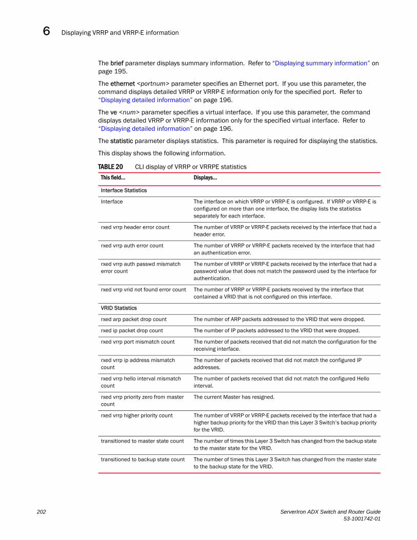
Displaying VRRP and VRRP-E information6DRAFT: BROCADE CONFIDENTIAL
The brief parameter displays summary information. Refer to “Displaying summary information” on page 195.
The ethernet <portnum> parameter specifies an Ethernet port. If you use this parameter, the command displays detailed VRRP or VRRP-E information only for the specified port. Refer to “Displaying detailed information” on page 196.
The ve <num> parameter specifies a virtual interface. If you use this parameter, the command displays detailed VRRP or VRRP-E information only for the specified virtual interface. Refer to “Displaying detailed information” on page 196.
The statistic parameter displays statistics. This parameter is required for displaying the statistics.
This display shows the following information.
TABLE 20 CLI display of VRRP or VRRPE statistics
This field... Displays...
Interface Statistics
Interface The interface on which VRRP or VRRP-E is configured. If VRRP or VRRP-E is configured on more than one interface, the display lists the statistics separately for each interface.
rxed vrrp header error count The number of VRRP or VRRP-E packets received by the interface that had a header error.
rxed vrrp auth error count The number of VRRP or VRRP-E packets received by the interface that had an authentication error.
rxed vrrp auth passwd mismatch error count
The number of VRRP or VRRP-E packets received by the interface that had a password value that does not match the password used by the interface for authentication.
rxed vrrp vrid not found error count The number of VRRP or VRRP-E packets received by the interface that contained a VRID that is not configured on this interface.
VRID Statistics
rxed arp packet drop count The number of ARP packets addressed to the VRID that were dropped.
rxed ip packet drop count The number of IP packets addressed to the VRID that were dropped.
rxed vrrp port mismatch count The number of packets received that did not match the configuration for the receiving interface.
rxed vrrp ip address mismatch count
The number of packets received that did not match the configured IP addresses.
rxed vrrp hello interval mismatch count
The number of packets received that did not match the configured Hello interval.
rxed vrrp priority zero from master count
The current Master has resigned.
rxed vrrp higher priority count The number of VRRP or VRRP-E packets received by the interface that had a higher backup priority for the VRID than this Layer 3 Switch’s backup priority for the VRID.
transitioned to master state count The number of times this Layer 3 Switch has changed from the backup state to the master state for the VRID.
transitioned to backup state count The number of times this Layer 3 Switch has changed from the master state to the backup state for the VRID.
202 ServerIron ADX Switch and Router Guide53-1001742-01

Displaying VRRP and VRRP-E information 6DRAFT: BROCADE CONFIDENTIAL
Clearing VRRP or VRRPE statisticsUse the following method to clear VRRP or VRRP-E statistics.
To clear VRRP or VRRP-E statistics, enter the following command at the Privileged EXEC level or any configuration level of the CLI.
Router1(config)# clear ip vrrp-stat
Syntax: clear ip vrrp-stat
Displaying CPU utilization statisticsYou can display CPU utilization statistics for VRRP and other IP protocols.
To display CPU utilization statistics for the previous one-second, one-minute, five-minute, and fifteen-minute intervals, enter the following command at any level of the CLI.
If the software has been running less than 15 minutes (the maximum interval for utilization statistics), the command indicates how long the software has been running. Here is an example:
To display utilization statistics for a specific number of seconds, enter a command such as the following.
ServerIronADX# show process cpuProcess Name 5Sec(%) 1Min(%) 5Min(%) 15Min(%) Runtime(ms)ARP 0.01 0.03 0.09 0.22 9GVRP 0.00 0.00 0.00 0.00 0ICMP 0.00 0.00 0.00 0.00 0IP 0.00 0.00 0.00 0.00 0OSPF 0.00 0.00 0.00 0.00 0RIP 0.00 0.00 0.00 0.00 0STP 0.00 0.00 0.00 0.00 0VRRP 0.03 0.07 0.09 0.10 8
ServerIronADX# show process cpuThe system has only been up for 6 seconds.Process Name 5Sec(%) 1Min(%) 5Min(%) 15Min(%) Runtime(ms)ARP 0.01 0.00 0.00 0.00 0GVRP 0.00 0.00 0.00 0.00 0ICMP 0.01 0.00 0.00 0.00 1IP 0.00 0.00 0.00 0.00 0OSPF 0.00 0.00 0.00 0.00 0RIP 0.00 0.00 0.00 0.00 0STP 0.00 0.00 0.00 0.00 0VRRP 0.00 0.00 0.00 0.00 0
ServerIron ADX Switch and Router Guide 20353-1001742-01

Configuration examples6DRAFT: BROCADE CONFIDENTIAL
When you specify how many seconds’ worth of statistics you want to display, the software selects the sample that most closely matches the number of seconds you specified. In this example, statistics are requested for the previous two seconds. The closest sample available is actually for the previous 1 second plus 80 milliseconds.
Syntax: show process cpu [<num>]
The <num> parameter specifies the number of seconds and can be from 1 – 900. If you use this parameter, the command lists the usage statistics only for the specified number of seconds. If you do not use this parameter, the command lists the usage statistics for the previous one-second, one-minute, five-minute, and fifteen-minute intervals.
Configuration examplesThe following sections contain the CLI commands for implementing the VRRP and VRRP-E configurations shown in Figure 52 on page 175 and Figure 53 on page 180.
VRRP exampleTo implement the VRRP configuration shown in Figure 52 on page 175, use either of the following methods.
Configuring Router1
To configure VRRP Router1, enter the following commands.
NOTEWhen you configure the Master (Owner), the address you enter with the ip-address command must already be configured on the interface.
ServerIronADX# show process cpu 2Statistics for last 1 sec and 80 msProcess Name Sec(%) Time(ms)ARP 0.00 0GVRP 0.00 0ICMP 0.01 1IP 0.00 0OSPF 0.00 0RIP 0.00 0STP 0.01 0VRRP 0.00 0
Router1(config)# router vrrpRouter1(config)# inter e 1/6Router1(config-if-1/6)# ip address 192.53.5.1Router1(config-if-1/6)# ip vrrp vrid 1Router1(config-if-1/6-vrid-1)# owner track-priority 20Router1(config-if-1/6-vrid-1)# track-port ethernet 2/4Router1(config-if-1/6-vrid-1)# ip-address 192.53.5.1Router1(config-if-1/6-vrid-1)# activate
204 ServerIron ADX Switch and Router Guide53-1001742-01
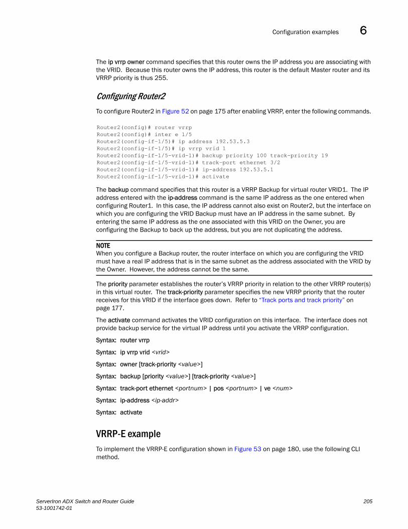
Configuration examples 6DRAFT: BROCADE CONFIDENTIAL
The ip vrrp owner command specifies that this router owns the IP address you are associating with the VRID. Because this router owns the IP address, this router is the default Master router and its VRRP priority is thus 255.
Configuring Router2
To configure Router2 in Figure 52 on page 175 after enabling VRRP, enter the following commands.
The backup command specifies that this router is a VRRP Backup for virtual router VRID1. The IP address entered with the ip-address command is the same IP address as the one entered when configuring Router1. In this case, the IP address cannot also exist on Router2, but the interface on which you are configuring the VRID Backup must have an IP address in the same subnet. By entering the same IP address as the one associated with this VRID on the Owner, you are configuring the Backup to back up the address, but you are not duplicating the address.
NOTEWhen you configure a Backup router, the router interface on which you are configuring the VRID must have a real IP address that is in the same subnet as the address associated with the VRID by the Owner. However, the address cannot be the same.
The priority parameter establishes the router’s VRRP priority in relation to the other VRRP router(s) in this virtual router. The track-priority parameter specifies the new VRRP priority that the router receives for this VRID if the interface goes down. Refer to “Track ports and track priority” on page 177.
The activate command activates the VRID configuration on this interface. The interface does not provide backup service for the virtual IP address until you activate the VRRP configuration.
Syntax: router vrrp
Syntax: ip vrrp vrid <vrid>
Syntax: owner [track-priority <value>]
Syntax: backup [priority <value>] [track-priority <value>]
Syntax: track-port ethernet <portnum> | pos <portnum> | ve <num>
Syntax: ip-address <ip-addr>
Syntax: activate
VRRP-E exampleTo implement the VRRP-E configuration shown in Figure 53 on page 180, use the following CLI method.
Router2(config)# router vrrpRouter2(config)# inter e 1/5Router2(config-if-1/5)# ip address 192.53.5.3Router2(config-if-1/5)# ip vrrp vrid 1Router2(config-if-1/5-vrid-1)# backup priority 100 track-priority 19Router2(config-if-1/5-vrid-1)# track-port ethernet 3/2Router2(config-if-1/5-vrid-1)# ip-address 192.53.5.1Router2(config-if-1/5-vrid-1)# activate
ServerIron ADX Switch and Router Guide 20553-1001742-01

Configuration examples6DRAFT: BROCADE CONFIDENTIAL
Configuring Router1
To configure VRRP Router1 in Figure 53 on page 180, enter the following commands.
Router1(config)# router vrrp-extendedRouter1(config)# interface ethernet 1/6Router1(config-if-1/6)# ip address 192.53.5.2/24Router1(config-if-1/6)# ip vrrp-extended vrid 1Router1(config-if-1/6-vrid-1)# backup priority 110 track-priority 20Router1(config-if-1/6-vrid-1)# track-port ethernet 2/4Router1(config-if-1/6-vrid-1)# ip-address 192.53.5.254Router1(config-if-1/6-vrid-1)# activateVRRP router 1 for this interface is activatingRouter1(config-if-1/6-vrid-1)# exitRouter1(config)# interface ethernet 1/6Router1(config-if-1/6)# ip vrrp-extended vrid 2Router1(config-if-1/6-vrid-1)# backup priority 100 track-priority 20Router1(config-if-1/6-vrid-1)# track-port ethernet 2/4Router1(config-if-1/6-vrid-1)# ip-address 192.53.5.253Router1(config-if-1/6-vrid-1)# activateVRRP router 2 for this interface is activating
NOTEThe address you enter with the ip-address command cannot be the same as a real IP address configured on the interface.
Configuring Router2
To configure Router2, enter the following commands.
Router2(config)# router vrrp-extendedRouter2(config)# interface ethernet 5/1Router2(config-if-5/1)# ip address 192.53.5.3/24Router2(config-if-5/1)# ip vrrp-extended vrid 1Router2(config-if-5/1-vrid-1)# backup priority 100 track-priority 20Router2(config-if-5/1-vrid-1)# track-port ethernet 3/2Router2(config-if-5/1-vrid-1)# ip-address 192.53.5.254Router2(config-if-5/1-vrid-1)# activateVRRP router 1 for this interface is activatingRouter2(config-if-5/1-vrid-1)# exitRouter2(config)# interface ethernet 5/1Router2(config-if-5/1)# ip vrrp-extended vrid 2Router2(config-if-5/1-vrid-1)# backup priority 110 track-priority 20Router2(config-if-5/1-vrid-1)# track-port ethernet 2/4Router2(config-if-5/1-vrid-1)# ip-address 192.53.5.253Router2(config-if-5/1-vrid-1)# activateVRRP router 2 for this interface is activating
The backup command specifies that this router is a VRRP-E Backup for virtual router VRID1. The IP address entered with the ip-address command is the same IP address as the one entered when configuring Router1. In this case, the IP address cannot also exist on Router2, but the interface on which you are configuring the VRID Backup must have an IP address in the same subnet. By entering the same IP address as the one associated with this VRID on the Owner, you are configuring the Backup to back up the address, but you are not duplicating the address.
206 ServerIron ADX Switch and Router Guide53-1001742-01

Configuring VRRP-E for IPv6 6DRAFT: BROCADE CONFIDENTIAL
NOTEWhen you configure a Backup router, the router interface on which you are configuring the VRID must have a real IP address that is in the same subnet as the address associated with the VRID by the Owner. However, the address cannot be the same.
The priority parameter establishes the router’s VRRP-E priority in relation to the other VRRP-E router(s) in this virtual router. The track-priority parameter specifies the new VRRPE priority that the router receives for this VRID if the interface goes down. Refer to “Track ports and track priority” on page 177.
The activate command activates the VRID configuration on this interface. The interface does not provide backup service for the virtual IP address until you activate the VRRP-E configuration. Alternatively, you can use the enable command. The activate and enable commands do the same thing.
Syntax: router vrrp-extended
Syntax: ip vrrp-extended vrid <vrid>
Syntax: backup [priority <value>] [track-priority <value>]
Syntax: track-port ethernet <portnum> | pos <portnum> | ve <num>
Syntax: ip-address <ip-addr>
Syntax: activate
Configuring VRRP-E for IPv6VRRP-E support for IPv6 addressing is available on ServerIron ADX beginning wih release 12.1.00.
Enabling IPv6 VRRP-E GloballyIPv6 VRRP-E is disabled by default. To enable the feature at the global configuration level, enter the following command.
ServerIronADX(config)# router vrrp-extended-ipv6
Syntax: [no] router vrrp-extended-ipv6
Enabling IPv6 VRRP-E on an InterfaceYou can enable IPv6 VRRP-E on an interface if VRRP-E has been enabled globally. To enable IPv6 VRRP-E on a physical or virtual routing interface, enter the following command.
ServerIronADX(config)# router vrrp-extended-ipv6ServerIronADX(config)# interface ethernet 1/5ServerIronADX(config-if-1/5)# ipv6 vrrp-extended vrid 1ServerIronADX(config-if-1/5-vrid-1)#
Syntax: [no] ipv6 vrrp-extended vrid <number>
For the <number>, variable enter 1 - 255.
ServerIron ADX Switch and Router Guide 20753-1001742-01

Configuring VRRP-E for IPv66DRAFT: BROCADE CONFIDENTIAL
Assigning Virtual VRRP-E Address in IPv6 FormatTo assign a VRRP-E address in IPv6 format, enter the following command.
ServerIronADX(config-if-1/5)# ipv6 vrrp-extended vrid 1ServerIronADX(config-if-1/5-vrid-1)# ip address fe80::cccc
Syntax: [no] ip address <ipv6 address>
NOTEOnly link-local IPV6 addresses are allowed to be configured as IP address of VRID. To assign link-local IPV6 address to VRID, port-interface should be either IPV6 enable or Global IPV6 address configured.
Setting Up Priority of VRRP-E InstanceTo assign a priority to a VRRP-E instance, use the following commands.
ServerIronADX(config-if-1/5)# ipv6 vrrp-extended vrid 1ServerIronADX(config-if-1/5-vrid-1)# backup priority 100
Syntax: [no] backup priority <priority>
For the <priority> variable enter a value between 6 and 255.
Setting Hello Interval on Master RouterTo set the Hello Interval for the Master, enter the following command.
ServerIronADX(config-if-1/5)# ipv6 vrrp-extended vrid 1ServerIronADX(config-if-1/5-vrid-1)# hello-interval 5
Syntax: [no] hello-interval <seconds>
For the <seconds> variable, enter a value from 1 to 84 seconds
Setting Backup Router Hello IntervalTo set the Hello interval for the Backup, enter the following command.
ServerIronADX(config-if-1/5)# ipv6 vrrp-extended vrid 1ServerIronADX(config-if-1/5-vrid-1)# backup-hello-interval 5
Syntax: [no] backup-hello-interval <seconds>
The <seconds> variable specifies the backup hello interval. It can be from 60 - 3600 seconds.
The default is 60 seconds.
Setting the Dead intervalTo set the dead interval, enter the following command.
ServerIronADX(config-if-1/5)# ipv6 vrrp-extended vrid 1ServerIronADX(config-if-1/5-vrid-1)# dead-interval 3
208 ServerIron ADX Switch and Router Guide53-1001742-01

Configuring VRRP-E for IPv6 6DRAFT: BROCADE CONFIDENTIAL
Syntax: [no] dead-interval <seconds>
The <seconds> variable specifies the dead interval.
Enabling Advertise BackupBy default, only the master ServerIron sends hello packets. To enable the standby ServerIron to send hello packets, issue the following command.
ServerIronADX(config-if-1/5)# ipv6 vrrp-extended vrid 1ServerIronADX(config-if-1/5-vrid-1)# advertise backup
Syntax: [no] advertise backup
Disabling the IPv6 VRRP-E instanceTo disable the IPv6 VRRP-E instance, enter the folowing command.
ServerIronADX(config-if-1/5)# ipv6 vrrp-extended vrid 1ServerIronADX(config-if-1/5-vrid-1)# disable
Syntax: disable
Tracking Port FailureTo track the link state of an interface with VRRP-E, use the following command.
ServerIronADX(config-if-1/5)# ipv6 vrrp-extended vrid 1ServerIronADX(config-if-1/5-vrid-1)# track-port ethernet 4
Syntax: [no] track-port ethernet [<slotnum>/]<portnum> | ve <number>
Sample ConfigurationVRRP-E is configured in pairs. The following is an example of a basic VRRP-E configuration.
Configuration for Router 1:ServerIronADX1(config)# router vrrp-extended-ipv6ServerIronADX1(config)# interface ethernet 1/5ServerIronADX1(config-if-1/5)# ipv6 address 1:1::1:1/64ServerIronADX1(config-if-1/5)# ipv6 vrrp-extended vrid 1ServerIronADX1(config-if-1/5-vrid-1)# backup priority 110ServerIronADX1(config-if-1/5-vrid-1)# ip address fe80::ccccServerIronADX1(config-if-1/5-vrid-1)# enable
Configuration for Router 2:ServerIronADX2(config)# router vrrp-extended-ipv6ServerIronADX2(config)# interface ethernet 1/5ServerIronADX2(config-if-1/5)# ipv6 address 1:1::1:2/64ServerIronADX2(config-if-1/5)# ipv6 vrrp-extended vrid 1ServerIronADX2(config-if-1/5-vrid-1)# backup priority 100ServerIronADX2(config-if-1/5-vrid-1)# ip address fe80::cccc
ServerIron ADX Switch and Router Guide 20953-1001742-01

Configuring VRRP-E for IPv66DRAFT: BROCADE CONFIDENTIAL
ServerIronADX2(config-if-1/5-vrid-1)# enable
Displaying IPv6 VRRP-E StatusUse the show ip vrrp-extended brief command to display the status of IPv4 and IPv6 instances.
ServerIronADX(config-if-e1000-1/5-vrid-1)#show ip vrrp-extended briefTotal number of VRRP-Extended routers defined: 1Interface VRID CurPri P State Master addr Backup addr VIP VRID GRP 1/5 1 100 P Master Local Unknown fe80::cccc N/A
Syntax: show ip vrrp-extended brief
Use the show ip vrrp-extended vrid <VRID> command to display the detailed information for an Individual VRID.
ServerIronADX(config)#show ip vrrp-extended vrid 1VRID 1 Interface ethernet 1/5 state master administrative-status enabled priority 100 current priority 100 hello-interval 1 sec dead-interval 0 sec current dead-interval 3.600 sec preempt-mode true virtual ip6 address fe80::cccc advertise backup: disabled next hello sent in 00:00:00
Syntax: show ip vrrp-extended vrid <VRID>
The <VRID> variable specifies the vrrp-extended ID. It is a decimal number.
NOTEIPv6 VRRP-E does not support track trunk port and track bp features.
210 ServerIron ADX Switch and Router Guide53-1001742-01

ServerIron ADX Switch and Router Guide53-1001742-01
DRAFT: BROCADE CONFIDENTIAL
Chapter
7
Configuring Uni-Directional Link Detection (UDLD)In this chapter•Configuration considerations . . . . . . . . . . . . . . . . . . . . . . . . . . . . . . . . . . . . 212
•Configuring UDLD . . . . . . . . . . . . . . . . . . . . . . . . . . . . . . . . . . . . . . . . . . . . . 213
•Displaying UDLD information . . . . . . . . . . . . . . . . . . . . . . . . . . . . . . . . . . . . 215
•Clearing UDLD statistics . . . . . . . . . . . . . . . . . . . . . . . . . . . . . . . . . . . . . . . . 217
This chapter describes how to configure the following features:
• Uni-directional Link Detection (UDLD)
• UDLD Holddown
Uni-directional Link Detection (UDLD) monitors a link between two Brocade devices and brings the ports on both ends of the link down if the link goes down at any point between the two devices. This feature is useful for links that are individual ports and for trunk links. Figure 54 shows an example.
FIGURE 54 UDLD example
Normally, a ServerIron ADX device load balances traffic across the ports in a trunk group. In this example, each Brocade device load balances traffic across two ports. Without the UDLD feature, a link failure on a link that is not directly attached to one of the ServerIron ADX switches is undetected by the ServerIron ADX switches. As a result, the ServerIron ADX switches continue to send traffic on the ports connected to the failed link.
When UDLD is enabled on the trunk ports on each ServerIron ADX switch, the switches detect the failed link, disable the ports connected to the failed link, and use the remaining ports in the trunk group to forward the traffic.
Without link keepalive, the ports remainenabled. Traffic continues to be load balanced to theports connected to the failed link.
When link keepalive is enabled, the featurebrings down the ports connectedto the failed link.
X
ServerIron ADX ServerIron ADX
Without link keepalive, the ports remainenabled. Traffic continues to be load balanced to theports connected to the failed link.
When link keepalive is enabled, the featurebrings down the ports connectedto the failed link.
211

Configuration considerations7DRAFT: BROCADE CONFIDENTIAL
Ports enabled for UDLD exchange proprietary health-check packets once every second (the keepalive interval). If a port does not receive a health-check packet from the port at the other end of the link within the keepalive interval, the port waits for two more intervals. If the port still does not receive a health-check packet after waiting for three intervals, the port concludes that the link has failed and takes the port down.
Configuration considerationsConsider the following while configuring UDLD:
• To configure UDLD on a trunk group, you must configure the feature on each port of the group individually. Configuring UDLD on a trunk group’s primary port enables the feature on that port only.
• If you want to configure a trunk group that contains ports on which UDLD is enabled, you must remove the UDLD configuration from the ports. After you create the trunk group, you can re-add the UDLD configuration.
• UDLD cannot be configured on a VLAN that is a member of a spanning tree instance.
• UDLD cannot be configured on a port that is a member of an LACP instance.
• There can only be one UDLD instance configured per-port.
• The maximum number of UDLD instances per ServerIron ADX is 32.
212 ServerIron ADX Switch and Router Guide53-1001742-01

Configuring UDLD 7DRAFT: BROCADE CONFIDENTIAL
Configuring UDLD with trunks
When configuring UDLD over load balancing trunks there can be a problem where a “hello” message goes out over one port and the response returns on a different port. In this situation, the ServerIron ADX that sent the “hello” message will go down when the response is received at the wrong port (because of load balancing) . This problem only occurs where there are multiple paths in the last hop. This is shown in first example in Figure 55.
There is no problem where there are trunks configured on links other than the last hop. The second example in Figure 55 shows an instance of this topology. Additionally, the split trunk topology shown at the bottom of Figure 55 does not have this problem.
FIGURE 55 UDLD over load sharing trunks
Configuring UDLD To enable UDLD on a port, enter a command such as the following at the global CONFIG level of the CLI.
ServerIron(config)# link-keepalive ethernet 1/1
Syntax: [no] link-keepalive ethernet <portnum> [ethernet <portnum>]
To enable the feature on a trunk group, enter commands such as the following.
ServerIron(config)# link-keepalive ethernet 1/1 ethernet 1/2ServerIron(config)# link-keepalive ethernet 1/3 ethernet 1/4
ServerIron ADX ServerIron ADX
ServerIron ADX ServerIron ADX
ServerIron ADX ServerIron ADX
Split Trunk Topolog
Mutiple paths in Last Hop
Single path in Last Hop
Both ports configured for UDLD
Both ports configured for UDLD
Port configured for UDLD
ServerIron ADX Switch and Router Guide 21353-1001742-01

Configuring UDLD7DRAFT: BROCADE CONFIDENTIAL
These commands enable UDLD on ports 1/1 – 1/4. You can specify up to two ports on the same command line.
Changing the Keepalive intervalBy default, ports enabled for UDLD send a link health-check packet once every 500 ms. You can change the interval to a value from 1 – 60, where 1 is 100 ms, 2 is 200 ms, and so on. To change the interval, enter a command such as the following.
ServerIron(config)# link-keepalive interval 3
Syntax: [no] link-keepalive interval <num>
The <num> parameter specifies how often the ports send a UDLD packet. You can specify from 1 – 60, in 100 ms increments. The default is 5 (500 ms).
Changing the Keepalive retriesBy default, a port waits one second to receive a health-check reply packet from the port at the other end of the link. If the port does not receive a reply, the port tries four more times by sending up to four more health-check packets. If the port still does not receive a reply after the maximum number of retries, the port goes down.
You can change the maximum number of keepalive attempts to a value from 3 – 10. To change the maximum number of attempts, enter a command such as the following.
ServerIron(config)# link-keepalive retries 4
Syntax: [no] link-keepalive retries <num>
The <num> parameter specifies the maximum number of times the port will try the health check. You can specify a value from 3 – 10. The default is 5.
UDLD for tagged and untagged ports portsIf UDLD is configured on an untagged port, it will run within the port’s default VLAN. In this situation, you cannot specify the VLAN to be used.
To allow ports to receive and send UDLD control packets tagged with a specific VLAN ID you must specify the VLAN ID of the VLAN to be used as shown in the following.
ServerIron(config)# link-keepalive ethernet 1/18 vlan 22
This commands enables UDLD on port 1/18 and allows UDLD control packet tagged with VLAN 22 to be received and sent on port 1/18.
Syntax: [no] link-keepalive ethernet <portnum> [vlan <vlan-ID>]
Enter the slot number (if applicable) and the port number of the Ethernet port.
Enter the ID of the VLAN that the UDLD control packets can contain to be received and sent on the port. If a VLAN ID is not specified, then UDLD control packets are sent out of the port as untagged packets.
214 ServerIron ADX Switch and Router Guide53-1001742-01

Displaying UDLD information 7DRAFT: BROCADE CONFIDENTIAL
NOTEYou must configure the same VLANs that will be used for UDLD on all devices across the network; otherwise, the UDLD link cannot be maintained.
Displaying UDLD information
Displaying information for all portsTo display UDLD information for all ports, enter the following command.
Syntax: show link-keepalive [ethernet <portnum>]
If a port is disabled by UDLD, the change also is indicated in the output of the show interfaces brief command. Here is an example:
TABLE 21 CLI display of UDLD information
This field... Displays...
Total link-keepalive enabled ports
The total number of ports on which UDLD is enabled.
Keepalive Retries The number of times a port will attempt the health check before concluding that the link is down.
Keepalive Interval The number of seconds between health check packets.
Port The port number.
Physical Link The state of the physical link. This is the link between the Brocade port and the directly connected device.
Logical Link The state of the logical link. This is the state of the link between this Brocade port and the Brocade port on the other end of the link.
State The traffic state of the port.
ServerIron(config)# show link-keepaliveTotal link-keepalive enabled ports: 4Keepalive Retries: 3 Keepalive Interval: 1 Sec.
Port Physical Link Logical Link State4/1 up up FORWARDING4/2 up up FORWARDING4/3 down down DISABLED4/4 up down DISABLED
ServerIron(config)# show interface brief
Port Link State Dupl Speed Trunk Tag Priori MAC Name1/1 Up LK-DISABLENone None None No level0 00e0.52a9.bb001/2 Down None None None None No level0 00e0.52a9.bb011/3 Down None None None None No level0 00e0.52a9.bb021/4 Down None None None None No level0 00e0.52a9.bb03
ServerIron ADX Switch and Router Guide 21553-1001742-01
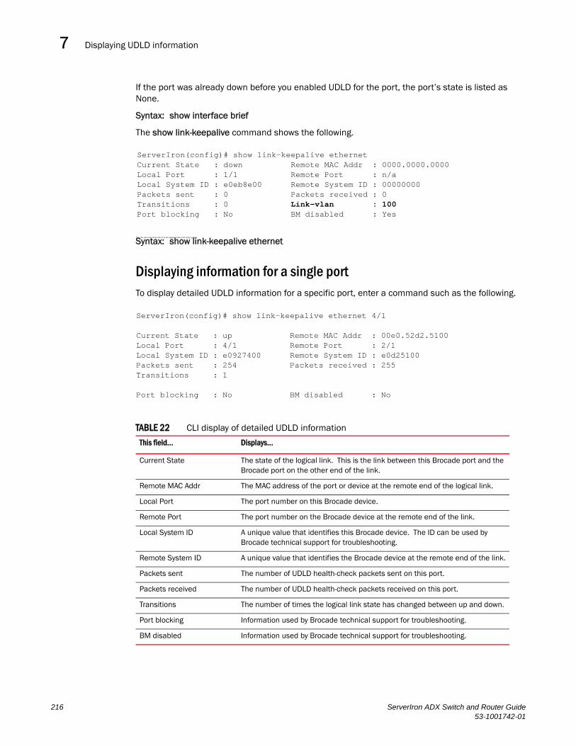
Displaying UDLD information7DRAFT: BROCADE CONFIDENTIAL
If the port was already down before you enabled UDLD for the port, the port’s state is listed as None.
Syntax: show interface brief
The show link-keepalive command shows the following.
The Link-vlan entry shows the ID of the tagged VLAN in the UDLD packet.
Syntax: show link-keepalive ethernet
Displaying information for a single portTo display detailed UDLD information for a specific port, enter a command such as the following.
TABLE 22 CLI display of detailed UDLD information
This field... Displays...
Current State The state of the logical link. This is the link between this Brocade port and the Brocade port on the other end of the link.
Remote MAC Addr The MAC address of the port or device at the remote end of the logical link.
Local Port The port number on this Brocade device.
Remote Port The port number on the Brocade device at the remote end of the link.
Local System ID A unique value that identifies this Brocade device. The ID can be used by Brocade technical support for troubleshooting.
Remote System ID A unique value that identifies the Brocade device at the remote end of the link.
Packets sent The number of UDLD health-check packets sent on this port.
Packets received The number of UDLD health-check packets received on this port.
Transitions The number of times the logical link state has changed between up and down.
Port blocking Information used by Brocade technical support for troubleshooting.
BM disabled Information used by Brocade technical support for troubleshooting.
ServerIron(config)# show link-keepalive ethernetCurrent State : down Remote MAC Addr : 0000.0000.0000Local Port : 1/1 Remote Port : n/aLocal System ID : e0eb8e00 Remote System ID : 00000000Packets sent : 0 Packets received : 0Transitions : 0 Link-vlan : 100 Port blocking : No BM disabled : Yes
ServerIron(config)# show link-keepalive ethernet 4/1
Current State : up Remote MAC Addr : 00e0.52d2.5100Local Port : 4/1 Remote Port : 2/1Local System ID : e0927400 Remote System ID : e0d25100Packets sent : 254 Packets received : 255Transitions : 1
Port blocking : No BM disabled : No
216 ServerIron ADX Switch and Router Guide53-1001742-01
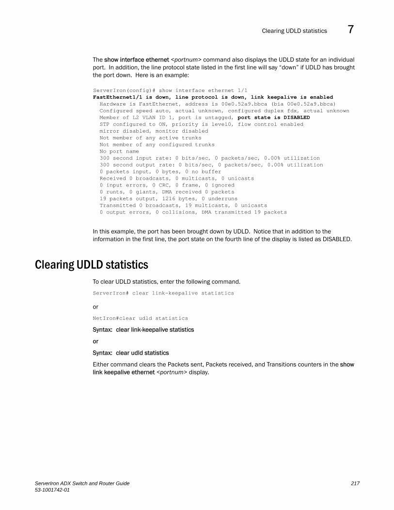
Clearing UDLD statistics 7DRAFT: BROCADE CONFIDENTIAL
The show interface ethernet <portnum> command also displays the UDLD state for an individual port. In addition, the line protocol state listed in the first line will say “down” if UDLD has brought the port down. Here is an example:
In this example, the port has been brought down by UDLD. Notice that in addition to the information in the first line, the port state on the fourth line of the display is listed as DISABLED.
Clearing UDLD statisticsTo clear UDLD statistics, enter the following command.
ServerIron# clear link-keepalive statistics
or
NetIron#clear udld statistics
Syntax: clear link-keepalive statistics
or
Syntax: clear udld statistics
Either command clears the Packets sent, Packets received, and Transitions counters in the show link keepalive ethernet <portnum> display.
ServerIron(config)# show interface ethernet 1/1FastEthernet1/1 is down, line protocol is down, link keepalive is enabled Hardware is FastEthernet, address is 00e0.52a9.bbca (bia 00e0.52a9.bbca) Configured speed auto, actual unknown, configured duplex fdx, actual unknown Member of L2 VLAN ID 1, port is untagged, port state is DISABLED STP configured to ON, priority is level0, flow control enabled mirror disabled, monitor disabled Not member of any active trunks Not member of any configured trunks No port name 300 second input rate: 0 bits/sec, 0 packets/sec, 0.00% utilization 300 second output rate: 0 bits/sec, 0 packets/sec, 0.00% utilization 0 packets input, 0 bytes, 0 no buffer Received 0 broadcasts, 0 multicasts, 0 unicasts 0 input errors, 0 CRC, 0 frame, 0 ignored 0 runts, 0 giants, DMA received 0 packets 19 packets output, 1216 bytes, 0 underruns Transmitted 0 broadcasts, 19 multicasts, 0 unicasts 0 output errors, 0 collisions, DMA transmitted 19 packets
ServerIron ADX Switch and Router Guide 21753-1001742-01

Clearing UDLD statistics7DRAFT: BROCADE CONFIDENTIAL
218 ServerIron ADX Switch and Router Guide53-1001742-01

ServerIron ADX Switch and Router Guide53-1001742-01
DRAFT: BROCADE CONFIDENTIAL
Chapter
8
Configuring IPIn this chapter•Basic configuration . . . . . . . . . . . . . . . . . . . . . . . . . . . . . . . . . . . . . . . . . . . . 219
•Overview. . . . . . . . . . . . . . . . . . . . . . . . . . . . . . . . . . . . . . . . . . . . . . . . . . . . . 220
•Basic IP parameters and defaults – Layer 3 Switches . . . . . . . . . . . . . . . . 225
•Basic IP parameters and defaults – Layer 2 Switches . . . . . . . . . . . . . . . . 229
•Configuring IP parameters – Layer 3 Switches . . . . . . . . . . . . . . . . . . . . . . 231
•Configuring IP parameters – Layer 2 Switches . . . . . . . . . . . . . . . . . . . . . . 270
•Displaying IP configuration information and statistics . . . . . . . . . . . . . . . . 277
This chapter describes the Internet Protocol (IP) parameters on Brocade Layer 2 Switches and Layer 3 Switches and how to configure them. After you add IP addresses and configure other IP parameters, refer to the following chapters for configuration information for the IP routing protocols:
• Chapter 9, “Configuring RIP”
• Chapter 10, “Configuring OSPF”
Basic configurationIP is enabled by default. Basic configuration consists of adding IP addresses and, for Layer 3 Switches, enabling a route exchange protocol, such as Routing Information Protocol (RIP):
• If you are configuring a Layer 3 Switch, refer to “Configuring IP addresses” on page 232 to add IP addresses, then see one or more of the following to enable and configure the route exchange protocols:
• “Configuring RIP parameters” on page 301
• “Configuring OSPF” on page 321
• If you are configuring a Layer 2 Switch, refer to “Configuring the management IP address and specifying the default gateway” on page 271 to add an IP address for management access through the network and to specify the default gateway.
The rest of this chapter describes IP and how to configure it in more detail. Use the information in this chapter if you need to change some of the IP parameters from their default values or you want to view configuration information or statistics.
219
Overview8DRAFT: BROCADE CONFIDENTIAL
OverviewProduct Name supports Internet Protocol (IP) version 4. IP support on Brocade Layer 2 Switches consists of basic services to support management access and access to a default gateway. IP support on Product Name includes all of the following, in addition to a highly configurable implementation of basic IP services including Address Resolution Protocol (ARP), ICMP Router Discovery Protocol (IRDP), and Reverse ARP (RARP):
• Route exchange protocols:
• Routing Information Protocol (RIP)
• Open Shortest Path First (OSPF)
• Router redundancy protocols:
• Virtual Router Redundancy Protocol Extended (VRRPE)
• Virtual Router Redundancy Protocol (VRRP)
• Brocade Standby Router Protocol (FSRP)
IP interfacesProduct Name switches allow you to configure IP addresses. With router code installed, IP addresses are associated with individual interfaces. With swtich code installed, a single IP address serves as the management access address for the entire device.
Product Name switches support configuration and display of IP address in classical subnet format (example: 192.168.1.1 255.255.255.0) and Classless Interdomain Routing (CIDR) format (example: 192.168.1.1/24). You can use either format when configuring IP address information. IP addresses are displayed in classical subnet format by default but you can change the display format to CIDR. Refer to “Changing the network mask display to prefix format” on page 277.
Product Name with router code installed
Product Name switches with router code installed allow you to configure IP addresses on the following types of interfaces:
• Ethernet ports
• Virtual routing interfaces (used by VLANs to route among one another)
• Loopback interfaces
Each IP address on a Product Name switch with router code must be in a different subnet. You can have only one interface that is in a given subnet. For example, you can configure IP addresses 192.168.1.1/24 and 192.168.2.1/24 on the same Product Name, but you cannot configure 192.168.1.1/24 and 192.168.1.2/24 on the same Product Name.
You can configure multiple IP addresses on the same interface.
You can use any of the IP addresses you configure on the Product Name for Telnet, Web management, or SNMP access.
Product Name with switch code installed
You can configure an IP address on a Product Name with switch code for management access to the it. An IP address is required for Telnet access, Web management access, and SNMP access.
220 ServerIron ADX Switch and Router Guide53-1001742-01

Overview 8DRAFT: BROCADE CONFIDENTIAL
You also can specify the default gateway for forwarding traffic to other subnets.
The following sections describe the IP tables and caches:
• ARP cache and static ARP table
• IP route table
• IP forwarding cache
The software enables you to display these tables. You also can change the capacity of the tables on an individual basis if needed by changing the memory allocation for the table.
ARP cache and static ARP table
The ARP cache contains entries that map IP addresses to MAC addresses. Generally, the entries are for devices that are directly attached to the Layer 3 Switch.
An exception is an ARP entry for an interface-based static IP route that goes to a destination that is one or more router hops away. For this type of entry, the MAC address is either the destination device’s MAC address or the MAC address of the router interface that answered an ARP request on behalf of the device, using proxy ARP.
ARP cacheThe ARP cache can contain dynamic (learned) entries and static (user-configured) entries. The software places a dynamic entry in the ARP cache when the Layer 3 Switch learns a device’s MAC address from an ARP request or ARP reply from the device.
The software can learn an entry when the Layer 2 Switch or Layer 3 Switch receives an ARP request from another IP forwarding device or an ARP reply. Here is an example of a dynamic entry.
Each entry contains the destination device’s IP address and MAC address.
Static ARP tableIn addition to the ARP cache, Layer 3 Switches have a static ARP table. Entries in the static ARP table are user-configured. You can add entries to the static ARP table regardless of whether the device the entry is for is connected to the Layer 3 Switch.
NOTEThe Layer 3 Switches have a static ARP table but Layer 2 Switches do not.
The software places an entry from the static ARP table into the ARP cache when the entry’s interface comes up.
Here is an example of a static ARP entry.
Index IP Address MAC Address Port 1 207.95.6.111 0800.093b.d210 1/1
Each entry lists the information you specified when you created the entry.
To display ARP entries, refer to the following:
• “Displaying the ARP cache” on page 284 – Layer 3 Switch
• “Displaying the static ARP table” on page 285 – Layer 3 Switch only
IP Address MAC Address Type Age Port1 207.95.6.102 0800.5afc.ea21 Dynamic 0 6
ServerIron ADX Switch and Router Guide 22153-1001742-01

Overview8DRAFT: BROCADE CONFIDENTIAL
• “Displaying ARP entries” on page 294 – Layer 2 Switch
To configure other ARP parameters, refer to the following:
• “Configuring ARP parameters” on page 241 – Layer 3 Switch only
IP route table
The IP route table contains paths to IP destinations.
NOTELayer 2 Switches do not have an IP route table. A Layer 2 Switch sends all packets addressed to another subnet to the default gateway, which you specify when you configure the basic IP information on the Layer 2 Switch.
The IP route table can receive the paths from the following sources:
• A directly-connected destination, which means there are no router hops to the destination
• A static IP route, which is a user-configured route
• A route learned through RIP
• A route learned through OSPF
The IP route table contains the best path to a destination.
• When the software receives paths from more than one of the sources listed above, the software compares the administrative distance of each path and selects the path with the lowest administrative distance. The administrative distance is a protocol-independent value from 1 – 255.
• When the software receives two or more best paths from the same source and the paths have the same metric (cost), the software can load share traffic among the paths based on destination host or network address (based on the configuration and the Layer 3 Switch model).
Here is an example of an entry in the IP route table:
Each IP route table entry contains the destination’s IP address and subnet mask and the IP address of the next-hop router interface to the destination. Each entry also indicates the port attached to the destination or the next-hop to the destination, the route’s IP metric (cost), and the type. The type indicates how the IP route table received the route.
To display the IP route table, refer to the following:
• “Displaying the IP route table” on page 287 – Layer 3 Switch only
To configure a static IP route, refer to the following:
• “Configuring static routes” on page 247 – Layer 3 Switch only
To clear a route from the IP route table, refer to the following:
• “Clearing IP routes” on page 290 – Layer 3 Switch only
• For learned routes, modify the ip-route parameter.
• For static routes, modify the ip-static-route parameter.
Destination NetMask Gateway Port Cost Type1.1.0.0 255.255.0.0 99.1.1.2 1/1 2 R
222 ServerIron ADX Switch and Router Guide53-1001742-01

Overview 8DRAFT: BROCADE CONFIDENTIAL
IP forwarding cache
The IP forwarding cache provides a fast-path mechanism for forwarding IP packets. The cache contains entries for IP destinations. When a Brocade Layer 3 Switch has completed processing and addressing for a packet and is ready to forward the packet, the device checks the IP forwarding cache for an entry to the packet’s destination.
• If the cache contains an entry with the destination IP address, the device uses the information in the entry to forward the packet out the ports listed in the entry. The destination IP address is the address of the packet’s final destination. The port numbers are the ports through which the destination can be reached.
• If the cache does not contain an entry and the traffic does not qualify for an entry in the session table instead, the software can create an entry in the forwarding cache.
Each entry in the IP forwarding cache has an age timer. If the entry remains unused for ten minutes, the software removes the entry. The age timer is not configurable.
Since routing is supported in hardware, packets hitting routing table entries in TCAM will be routed by hardware without CPU intervention. Only packets destined to direct-connected hosts will show up in the forwarding cache since their first packets will hit the CPU before hardware entries are programmed. Once procrammed in hardware, packets destined to direct-connected hosts will no longer be forwarded to the CPU untill they are aged out.
Here is an example of an entry in the IP forwarding cache.
Each IP forwarding cache entry contains the IP address of the destination, and the IP address and MAC address of the next-hop router interface to the destination. If the destination is actually an interface configured on the Layer 3 Switch itself, as shown here, then next-hop information indicates this. The port through which the destination is reached is also listed, as well as the VLAN and Layer 4 QoS priority associated with the destination if applicable.
To display the IP forwarding cache, refer to “Displaying the forwarding cache” on page 286.
NOTEYou cannot add static entries to the IP forwarding cache, although the Product Name does have options to optimize the cache and increase the number of entries the cache can contain. Refer to “Displaying and modifying system parameter default settings” on page 22 for more information.
To increase the size of the IP forwarding cache, refer to “Displaying and modifying system parameter default settings” on page 22 for more information.
IP route exchange protocolsThe ServerIron ADX supports the following IP route exchange protocols:
• Routing Information Protocol (RIP)
• Open Shortest Path First (OSPF)
All these protocols provide routes to the IP route table. You can use one or more of these protocols, in any combination. The protocols are disabled by default. For configuration information, refer to the following:
• Chapter 9, “Configuring RIP”
IP Address Next Hop MAC Type Port Vlan Pri1 192.168.1.11 DIRECT 0000.0000.0000 PU n/a 0
ServerIron ADX Switch and Router Guide 22353-1001742-01

Overview8DRAFT: BROCADE CONFIDENTIAL
• Chapter 10, “Configuring OSPF”
IP interface redundancy protocolsYou can configure aServerIron ADX switch to back up an IP interface configured on another ServerIron ADX switch. If the link for the backed up interface becomes unavailable, the other ServerIron ADX switch can continue service for the interface. This feature is especially useful for providing a backup to a network’s default gateway.
ServerIron ADX switches support the following IP interface redundancy protocols:
• Virtual Router Redundancy Protocol (VRRP) – A standard router redundancy protocol based on RFC 2338. You can use VRRP to configure Brocade Layer 3 Switches and third-party routers to back up IP interfaces on other Brocade Layer 3 Switches or third-party routers.
• Virtual Router Redundancy Protocol Extended (VRRPE) – A Brocade extension to standard VRRP that adds additional features and overcomes limitations in standard VRRP. You can use VRRPE only on Brocade Layer 3 Switches.
• Brocade Standby Router Protocol (FSRP) – A Brocade router redundancy protocol developed before VRRP and VRRPE that provides some of the features of VRRP and some of the features of VRRPE. You can use FSRP only on Brocade Layer 3 Switches.
For configuration information, refer to the following:
• Virtual Router Redundancy Protocol Extended (VRRPE) – refer to “Configuring VRRP and VRRP-E” on page 173.
• Virtual Router Redundancy Protocol (VRRP) – refer to “Configuring VRRP and VRRP-E” on page 173.
Network Address Translation Brocade’s Chassis Layer 3 Switches support Network Address Translation (NAT). NAT enables private IP networks that use nonregistered IP addresses to connect to the Internet. Configure NAT on a Brocade Layer 3 Switch that is placed at the border of an inside network and an outside network (such as the Internet). NAT translates the internal local addresses to globally unique IP addresses before sending packets to the outside network.
For configuration information, refer to “Network Address Translation” on page 224.
Access Control Lists and IP access policies Brocade Layer 3 Switches provide two mechanisms for filtering IP traffic:
• Access Control Lists (ACLs)
• IP access policies
Both methods allow you to filter packets based on Layer 3 and Layer 4 source and destination information.
ACLs also provide the input for Policy-Based Routing (PBR), which allows you to selectively modify and route IP packets based on their source IP address.
IP access policies allow you to configure QoS based on sessions (Layer 4 traffic flows).
224 ServerIron ADX Switch and Router Guide53-1001742-01
Basic IP parameters and defaults – Layer 3 Switches 8DRAFT: BROCADE CONFIDENTIAL
Only one of these filtering mechanisms can be enabled on a Brocade device at a time. Brocade devices can store forwarding information for both methods of filtering in the session table.
For configuration information, refer to the following:
• “Access Control Lists and IP access policies” on page 224
Basic IP parameters and defaults – Layer 3 SwitchesIP is enabled by default. The following IP-based protocols are all disabled by default:
• Routing protocols:
• Routing Information Protocol (RIP) – refer to “Configuring RIP parameters” on page 301
• Open Shortest Path First (OSPF) – refer to “Configuring OSPF” on page 313
• Router redundancy protocols:
• Virtual Router Redundancy Protocol Extended (VRRPE) – refer to “Configuring VRRP and VRRP-E” on page 173.
• Virtual Router Redundancy Protocol (VRRP) – refer to “Configuring VRRP and VRRP-E” on page 173.
The following tables list the Layer 3 Switch IP parameters, their default values, and where to find configuration information.
NOTEFor information about parameters in other protocols based on IP, such as RIP, OSPF, and so on, refer to the configuration chapters for those protocols.
When parameter changes take effectMost IP parameters described in this chapter are dynamic. They take effect immediately, as soon as you enter the CLI command or select the Web management interface option. You can verify that a dynamic change has taken effect by displaying the running-config. To display the running-config, enter the show running-config or write terminal command at any CLI prompt. (You cannot display the running-config from the Web management interface.)
To save a configuration change permanently so that the change remains in effect following a system reset or software reload, save the change to the startup-config file:
• To save configuration changes to the startup-config file, enter the write memory command from the Privileged EXEC level of any configuration level of the CLI.
• To save the configuration changes using the Web management interface, select the Save link at the bottom of the dialog. Select Yes when prompted to save the configuration change to the startup-config file on the device’s flash memory. You also can access the dialog for saving configuration changes by clicking on Command in the tree view, then clicking on Save to Flash.
Changes to memory allocation require you to reload the software after you save the changes to the startup-config file. When reloading the software is required to complete a configuration change described in this chapter, the procedure that describes the configuration change includes a step for reloading the software.
ServerIron ADX Switch and Router Guide 22553-1001742-01
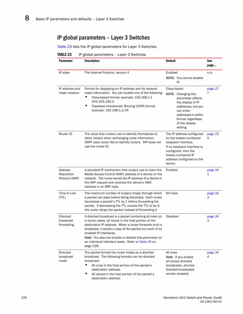
Basic IP parameters and defaults – Layer 3 Switches8DRAFT: BROCADE CONFIDENTIAL
IP global parameters – Layer 3 SwitchesTable 23 lists the IP global parameters for Layer 3 Switches.
TABLE 23 IP global parameters – Layer 3 Switches
Parameter Description Default See page...
IP state The Internet Protocol, version 4 Enabled
NOTE: You cannot disable IP.
n/a
IP address and mask notation
Format for displaying an IP address and its network mask information. You can enable one of the following:• Class-based format; example: 192.168.1.1
255.255.255.0• Classless Interdomain Routing (CIDR) format;
example: 192.168.1.1/24
Class-based
NOTE: Changing this parameter affects the display of IP addresses, but you can enter addresses in either format regardless of the display setting.
page 277
Router ID The value that routers use to identify themselves to other routers when exchanging route information. OSPF uses router IDs to identify routers. RIP does not use the router ID.
The IP address configured on the lowest-numbered loopback interface.If no loopback interface is configured, then the lowest-numbered IP address configured on the device.
page 239
Address Resolution Protocol (ARP)
A standard IP mechanism that routers use to learn the Media Access Control (MAC) address of a device on the network. The router sends the IP address of a device in the ARP request and receives the device’s MAC address in an ARP reply.
Enabled page 241
Time to Live (TTL)
The maximum number of routers (hops) through which a packet can pass before being discarded. Each router decreases a packet’s TTL by 1 before forwarding the packet. If decreasing the TTL causes the TTL to be 0, the router drops the packet instead of forwarding it.
64 hops page 243
Directed broadcast forwarding
A directed broadcast is a packet containing all ones (or in some cases, all zeros) in the host portion of the destination IP address. When a router forwards such a broadcast, it sends a copy of the packet out each of its enabled IP interfaces. Note: You also can enable or disable this parameter on an individual interface basis. Refer to Table 24 on page 228.
Disabled page 243
Directed broadcast mode
The packet format the router treats as a directed broadcast. The following formats can be directed broadcast:• All ones in the host portion of the packet’s
destination address.• All zeroes in the host portion of the packet’s
destination address.
All onesNote: If you enable all-zeroes directed broadcasts, all-ones directed broadcasts remain enabled.
page 244
226 ServerIron ADX Switch and Router Guide53-1001742-01

Basic IP parameters and defaults – Layer 3 Switches 8DRAFT: BROCADE CONFIDENTIAL
Source-routed packet forwarding
A source-routed packet contains a list of IP addresses through which the packet must pass to reach its destination.
Enabled page 244
Internet Control Message Protocol (ICMP) messages
The Product Name Layer 3 Switch can send the following types of ICMP messages:• Echo messages (ping messages)• Destination Unreachable messages• Redirect messages
NOTE: You also can enable or disable ICMP Redirect messages on an individual interface basis. Refer to Table 24 on page 228.
Enabled page 245page 247
ICMP Router Discovery Protocol (IRDP)
An IP protocol a router can use to advertise the IP addresses of its router interfaces to directly attached hosts. You can enable or disable the protocol, and change the following protocol parameters:• Forwarding method (broadcast or multicast)• Hold time• Maximum advertisement interval• Minimum advertisement interval• Router preference level
NOTE: You also can enable or disable IRDP and configure the parameters on an individual interface basis. Refer to Table 24 on page 228.
Disabled page 262
Reverse ARP (RARP)
An IP mechanism a host can use to request an IP address from a directly attached router when the host boots.
Enabled page 264
Static RARP entries
An IP address you place in the RARP table for RARP requests from hosts.
NOTE: You must enter the RARP entries manually. The Layer 3 Switch does not have a mechanism for learning or dynamically generating RARP entries.
No entries page 265
Maximum BootP relay hops
The maximum number of hops away a BootP server can be located from a router and still be used by the router’s clients for network booting.
Four page 270
Domain name for Domain Name Server (DNS) resolver
A domain name (example: borcade.router.com) you can use in place of an IP address for certain operations such as IP pings, trace routes, and Telnet management connections to the router.
None configured page 234
DNS default gateway addresses
A list of gateways attached to the router through which clients attached to the router can reach DNSs.
None configured page 234
TABLE 23 IP global parameters – Layer 3 Switches (Continued)
Parameter Description Default See page...
ServerIron ADX Switch and Router Guide 22753-1001742-01

Basic IP parameters and defaults – Layer 3 Switches8DRAFT: BROCADE CONFIDENTIAL
IP interface parameters – Layer 3 SwitchesTable 24 lists the interface-level IP parameters for Layer 3 Switches.
IP load sharing A feature that enables the router to balance traffic to a specific destination across multiple equal-cost paths. IP load sharing uses a hash mechanism based on destination address, source address, and the protocol of the packet to choose one of multiple paths.
NOTE: Load sharing is sometimes called Equal Cost Multi Path (ECMP).
Enabled page 257
Maximum IP load sharing paths
The maximum number of equal-cost paths across which the Layer 3 Switch is allowed to distribute traffic.
Four page 262
CAM programming
Whether the device programs separate route entries into the CAM for individual route destinations or programs single aggregate entries for multiple destinations.
Separate entries are programmed for each destination
page 262
Default network route
The router uses the default network route if the IP route table does not contain a route to the destination and also does not contain an explicit default route (0.0.0.0 0.0.0.0 or 0.0.0.0/0).
None configured page 256
Static route An IP route you place in the IP route table. No entries page 247
Source interface
The IP address the router uses as the source address for Telnet, RADIUS, or TACACS/TACACS+ packets originated by the router. The router can select the source address based on either of the following:• The lowest-numbered IP address on the interface
the packet is sent on.• The lowest-numbered IP address on a specific
interface. The address is used as the source for all packets of the specified type regardless of interface the packet is sent on.
The lowest-numbered IP address on the interface the packet is sent on.
page 239
TABLE 24 IP interface parameters – Product Name
Parameter Description Default See page...
IP address A Layer 3 network interface address
NOTE: Layer 2 Switches have a single IP address used for management access to the entire device. Layer 3 Switches have separate IP addresses on individual interfaces.
None configured page 232
Directed broadcast forwarding
Locally overrides the global setting. Refer to Table 23 on page 226.
Disabled page 243
ICMP Router Discovery Protocol (IRDP)
Locally overrides the global IRDP settings. Refer to Table 23 on page 226.
Disabled page 263
TABLE 23 IP global parameters – Layer 3 Switches (Continued)
Parameter Description Default See page...
228 ServerIron ADX Switch and Router Guide53-1001742-01

Basic IP parameters and defaults – Layer 2 Switches 8DRAFT: BROCADE CONFIDENTIAL
Basic IP parameters and defaults – Layer 2 SwitchesIP is enabled by default. The following tables list the Layer 2 Switch IP parameters, their default values, and where to find configuration information.
IP global parameters – Layer 2 SwitchesTable 25 lists the IP global parameters for Layer 2 Switches.
ICMP Redirect messages
Locally overrides the global setting. Refer to Table 23 on page 226.
Enabled page 247
DHCP gateway stamp
The router can assist DHCP/BootP Discovery packets from one subnet to reach DHCP/BootP servers on a different subnet by placing the IP address of the router interface that receives the request in the request packet’s Gateway field. You can override the default and specify the IP address to use for the Gateway field in the packets.
NOTE: UDP broadcast forwarding for client DHCP/BootP requests (bootpc) must be enabled and you must configure an IP helper address (the server’s IP address or a directed broadcast to the server’s subnet) on the port connected to the client.
The lowest-numbered IP address on the interface that receives the request
page 270
UDP broadcast forwarding
The router can forward UDP broadcast packets for UDP applications such as BootP. By forwarding the UDP broadcasts, the router enables clients on one subnet to find servers attached to other subnets.
NOTE: To completely enable a client’s UDP application request to find a server on another subnet, you must configure an IP helper address consisting of the server’s IP address or the directed broadcast address for the subnet that contains the server. See the next row.
The router helps forward broadcasts for the following UDP application protocols:• bootps• dns• netbios-dgm• netbios-ns• tacacs• tftp• time
page 267
IP helper address The IP address of a UDP application server (such as a BootP or DHCP server) or a directed broadcast address. IP helper addresses allow the router to forward requests for certain UDP applications from a client on one subnet to a server on another subnet.
None configured page 268
Metric A numeric cost the router adds to RIP routes learned on the interface. This parameter applies only to RIP routes.
1 (one) -302
IP state The Internet Protocol, version 4 Enabled
NOTE: You cannot disable IP.
n/a
TABLE 24 IP interface parameters – Product Name (Continued)
Parameter Description Default See page...
ServerIron ADX Switch and Router Guide 22953-1001742-01
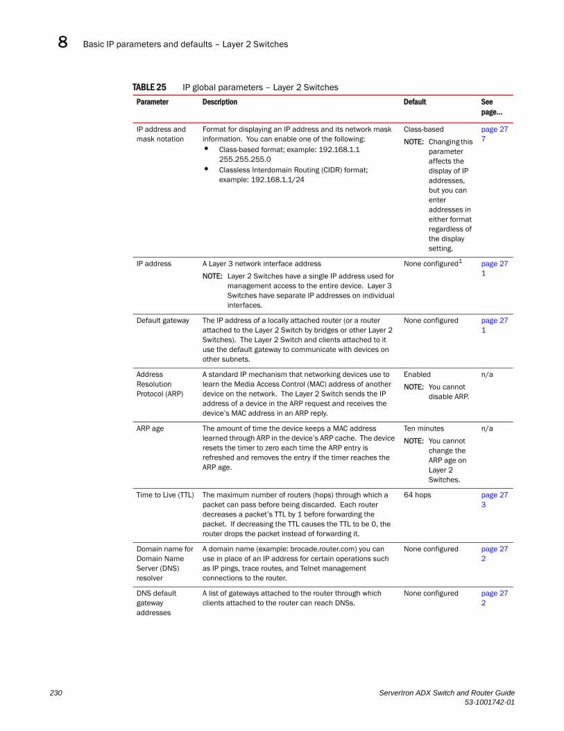
Basic IP parameters and defaults – Layer 2 Switches8DRAFT: BROCADE CONFIDENTIAL
TABLE 25 IP global parameters – Layer 2 Switches
Parameter Description Default See page...
IP address and mask notation
Format for displaying an IP address and its network mask information. You can enable one of the following:• Class-based format; example: 192.168.1.1
255.255.255.0• Classless Interdomain Routing (CIDR) format;
example: 192.168.1.1/24
Class-based
NOTE: Changing this parameter affects the display of IP addresses, but you can enter addresses in either format regardless of the display setting.
page 277
IP address A Layer 3 network interface address
NOTE: Layer 2 Switches have a single IP address used for management access to the entire device. Layer 3 Switches have separate IP addresses on individual interfaces.
None configured1 page 271
Default gateway The IP address of a locally attached router (or a router attached to the Layer 2 Switch by bridges or other Layer 2 Switches). The Layer 2 Switch and clients attached to it use the default gateway to communicate with devices on other subnets.
None configured page 271
Address Resolution Protocol (ARP)
A standard IP mechanism that networking devices use to learn the Media Access Control (MAC) address of another device on the network. The Layer 2 Switch sends the IP address of a device in the ARP request and receives the device’s MAC address in an ARP reply.
Enabled
NOTE: You cannot disable ARP.
n/a
ARP age The amount of time the device keeps a MAC address learned through ARP in the device’s ARP cache. The device resets the timer to zero each time the ARP entry is refreshed and removes the entry if the timer reaches the ARP age.
Ten minutes
NOTE: You cannot change the ARP age on Layer 2 Switches.
n/a
Time to Live (TTL) The maximum number of routers (hops) through which a packet can pass before being discarded. Each router decreases a packet’s TTL by 1 before forwarding the packet. If decreasing the TTL causes the TTL to be 0, the router drops the packet instead of forwarding it.
64 hops page 273
Domain name for Domain Name Server (DNS) resolver
A domain name (example: brocade.router.com) you can use in place of an IP address for certain operations such as IP pings, trace routes, and Telnet management connections to the router.
None configured page 272
DNS default gateway addresses
A list of gateways attached to the router through which clients attached to the router can reach DNSs.
None configured page 272
230 ServerIron ADX Switch and Router Guide53-1001742-01
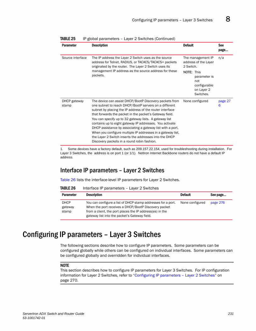
Configuring IP parameters – Layer 3 Switches 8DRAFT: BROCADE CONFIDENTIAL
Interface IP parameters – Layer 2 SwitchesTable 26 lists the interface-level IP parameters for Layer 2 Switches.
Configuring IP parameters – Layer 3 SwitchesThe following sections describe how to configure IP parameters. Some parameters can be configured globally while others can be configured on individual interfaces. Some parameters can be configured globally and overridden for individual interfaces.
NOTEThis section describes how to configure IP parameters for Layer 3 Switches. For IP configuration information for Layer 2 Switches, refer to “Configuring IP parameters – Layer 2 Switches” on page 270.
Source interface The IP address the Layer 2 Switch uses as the source address for Telnet, RADIUS, or TACACS/TACACS+ packets originated by the router. The Layer 2 Switch uses its management IP address as the source address for these packets.
The management IP address of the Layer 2 Switch.
NOTE: This parameter is not configurable on Layer 2 Switches.
n/a
DHCP gateway stamp
The device can assist DHCP/BootP Discovery packets from one subnet to reach DHCP/BootP servers on a different subnet by placing the IP address of the router interface that forwards the packet in the packet’s Gateway field. You can specify up to 32 gateway lists. A gateway list contains up to eight gateway IP addresses. You activate DHCP assistance by associating a gateway list with a port.When you configure multiple IP addresses in a gateway list, the Layer 2 Switch inserts the addresses into the DHCP Discovery packets in a round robin fashion.
None configured page 276
1. Some devices have a factory default, such as 209.157.22.154, used for troubleshooting during installation. For Layer 3 Switches, the address is on port 1 (or 1/1). NetIron Internet Backbone routers do not have a default IP address.
TABLE 26 Interface IP parameters – Layer 2 Switches
Parameter Description Default See page...
DHCP gateway stamp
You can configure a list of DHCP stamp addresses for a port. When the port receives a DHCP/BootP Discovery packet from a client, the port places the IP address(es) in the gateway list into the packet’s Gateway field.
None configured page 276
TABLE 25 IP global parameters – Layer 2 Switches (Continued)
Parameter Description Default See page...
ServerIron ADX Switch and Router Guide 23153-1001742-01

Configuring IP parameters – Layer 3 Switches8DRAFT: BROCADE CONFIDENTIAL
Configuring IP addressesYou can configure an IP address on the following types of Layer 3 Switch interfaces:
• Ethernet port
• Virtual routing interface (also called a Virtual Ethernet or “VE”)
• Loopback interface
By default, you can configure up to 32 IP addresses on each interface. You can increase this amount to up to 128 IP subnet addresses per port by increasing the size of the subnet-per-interface table.
NOTEOnce you configure a virtual routing interface on a VLAN, you cannot configure Layer 3 interface parameters on individual ports in the VLAN. Instead, you must configure the parameters on the virtual routing interface itself.
Brocade devices support both classical IP network masks (Class A, B, and C subnet masks, and so on) and Classless Interdomain Routing (CIDR) network prefix masks:
• To enter a classical network mask, enter the mask in IP address format. For example, enter “209.157.22.99 255.255.255.0” for an IP address with a Class-C subnet mask.
• To enter a prefix network mask, enter a forward slash ( / ) and the number of bits in the mask immediately after the IP address. For example, enter “209.157.22.99/24” for an IP address that has a network mask with 24 significant bits (ones).
By default, the CLI displays network masks in classical IP address format (example: 255.255.255.0). You can change the display to prefix format. Refer to “Changing the network mask display to prefix format” on page 277.
Assigning an IP address to an Ethernet port
To assign an IP address to port 1/1, enter the following commands.
Product Name(config)# interface ethernet 1/1Product Name(config-if-1/1)# ip address 192.45.6.1 255.255.255.0
NOTEYou also can enter the IP address and mask in CIDR format, as follows.Product Name(config-if-1/1)# ip address 192.45.6.1/24
Syntax: [no] ip address <ip-addr> <ip-mask> [ospf-ignore | ospf-passive | secondary]
or
Syntax: [no] ip address <ip-addr>/<mask-bits> [ospf-ignore | ospf-passive | secondary]
The ospf-ignore | ospf-passive parameters modify the Layer 3 Switch defaults for adjacency formation and interface advertisement. Use one of these parameters if you are configuring multiple IP subnet addresses on the interface but you want to prevent OSPF from running on some of the subnets.
• ospf-passive – This option disables adjacency formation with OSPF neighbors. By default, when OSPF is enabled on an interface, the software forms OSPF router adjacencies between each primary IP address on the interface and the OSPF neighbor attached to the interface.
232 ServerIron ADX Switch and Router Guide53-1001742-01

Configuring IP parameters – Layer 3 Switches 8DRAFT: BROCADE CONFIDENTIAL
• ospf-ignore – This option disables OSPF adjacency formation and also disables advertisement of the interface into OSPF. The subnet is completely ignored by OSPF.
NOTEThe ospf-passive option disables adjacency formation but does not disable advertisement of the interface into OSPF. To disable advertisement in addition to disabling adjacency formation, you must use the ospf-ignore option.
Use the secondary parameter if you have already configured an IP address within the same subnet on the interface.
NOTEWhen you configure more than one address in the same subnet, all but the first address are secondary addresses and do not form OSPF adjacencies.
Assigning an IP address to a loopback interface
Loopback interfaces are always up, regardless of the states of physical interfaces. They can add stability to the network because they are not subject to route flap problems that can occur due to unstable links between a Layer 3 Switch and other devices. You can configure up to eight loopback interfaces on a Chassis Layer 3 Switch and up to four loopback interfaces ona Stackable Layer 3 Switch.
You can add up to 24 IP addresses to each loopback interface.
To add a loopback interface, enter commands such as those shown in the following example.
ServerIron(config)# int loopback 1ServerIron(config-lbif-1)# ip address 10.0.0.1/24
Syntax: interface loopback <num>
The <num> parameter specifies the virtual interface number. You can specify from 1 to the maximum number of virtual interfaces supported on the device. To display the maximum number of virtual interfaces supported on the device, enter the show default values command. The maximum is listed in the System Parameters section, in the Current column of the virtual-interface row.
Refer to the syntax description in “Assigning an IP address to an Ethernet port” on page 232.
Assigning an IP address to a virtual interface
A virtual interface is a logical port associated with a Layer 3 Virtual LAN (VLAN) configured on a Layer 3 Switch. You can configure routing parameters on the virtual interface to enable the Layer 3 Switch to route protocol traffic from one Layer 3 VLAN to the other, without using an external router.1
You can configure IP, IPX, or AppleTalk routing interface parameters on a virtual interface. This section describes how to configure an IP address on a virtual interface. Other sections in this chapter that describe how to configure interface parameters also apply to virtual interfaces.
1. Brocade’s feature that allows routing between VLANs within the same device, without the need for external routers, is called Integrated Switch Routing (ISR).
ServerIron ADX Switch and Router Guide 23353-1001742-01
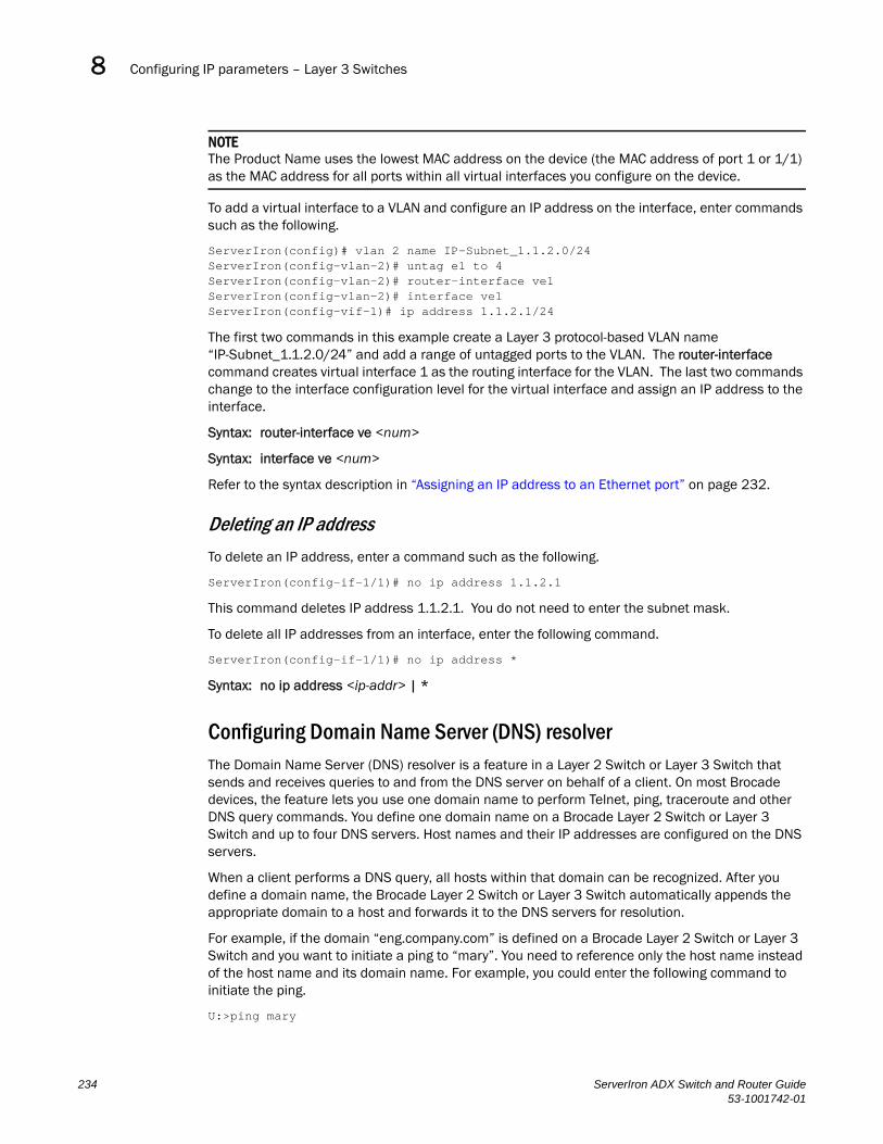
Configuring IP parameters – Layer 3 Switches8DRAFT: BROCADE CONFIDENTIAL
NOTEThe Product Name uses the lowest MAC address on the device (the MAC address of port 1 or 1/1) as the MAC address for all ports within all virtual interfaces you configure on the device.
To add a virtual interface to a VLAN and configure an IP address on the interface, enter commands such as the following.
ServerIron(config)# vlan 2 name IP-Subnet_1.1.2.0/24ServerIron(config-vlan-2)# untag e1 to 4ServerIron(config-vlan-2)# router-interface ve1ServerIron(config-vlan-2)# interface ve1ServerIron(config-vif-1)# ip address 1.1.2.1/24
The first two commands in this example create a Layer 3 protocol-based VLAN name “IP-Subnet_1.1.2.0/24” and add a range of untagged ports to the VLAN. The router-interface command creates virtual interface 1 as the routing interface for the VLAN. The last two commands change to the interface configuration level for the virtual interface and assign an IP address to the interface.
Syntax: router-interface ve <num>
Syntax: interface ve <num>
Refer to the syntax description in “Assigning an IP address to an Ethernet port” on page 232.
Deleting an IP address
To delete an IP address, enter a command such as the following.
ServerIron(config-if-1/1)# no ip address 1.1.2.1
This command deletes IP address 1.1.2.1. You do not need to enter the subnet mask.
To delete all IP addresses from an interface, enter the following command.
ServerIron(config-if-1/1)# no ip address *
Syntax: no ip address <ip-addr> | *
Configuring Domain Name Server (DNS) resolverThe Domain Name Server (DNS) resolver is a feature in a Layer 2 Switch or Layer 3 Switch that sends and receives queries to and from the DNS server on behalf of a client. On most Brocade devices, the feature lets you use one domain name to perform Telnet, ping, traceroute and other DNS query commands. You define one domain name on a Brocade Layer 2 Switch or Layer 3 Switch and up to four DNS servers. Host names and their IP addresses are configured on the DNS servers.
When a client performs a DNS query, all hosts within that domain can be recognized. After you define a domain name, the Brocade Layer 2 Switch or Layer 3 Switch automatically appends the appropriate domain to a host and forwards it to the DNS servers for resolution.
For example, if the domain “eng.company.com” is defined on a Brocade Layer 2 Switch or Layer 3 Switch and you want to initiate a ping to “mary”. You need to reference only the host name instead of the host name and its domain name. For example, you could enter the following command to initiate the ping.
U:>ping mary
234 ServerIron ADX Switch and Router Guide53-1001742-01

Configuring IP parameters – Layer 3 Switches 8DRAFT: BROCADE CONFIDENTIAL
The Brocade Layer 2 Switch or Layer 3 Switch qualifies the host name by appending a domain name. For example, mary.eng.company.com. This qualified name is sent to the DNS server for resolution. If there are four DNS servers configured, it is sent to the first DNS server. If the host name is not resolved, it is sent to the second DNS server. If a match is found, a response is sent back to the client with the host’s IP address. If no match is found, a “unknown host” message is returned. (Refer to Figure 56.)
FIGURE 56 DNS resolution with one domain name
You can create a list of domain names that can be used to resolve host names. This list can have more than one domain name. When a client performs a DNS query all hosts within the domains on the list can be recognized and queries can be sent to any domain on the list.
Also, the Product Name device now contains a DNS cache table that contains a list of host names that have been resolved to their IP addresses. This DNS cache table allows DNS queries to be processed quickly. When a DNS query is made, the query can be sent to the DNS cache table. If a match is found, the DNS query is resolved. If no match is found, the DNS query is sent to the DNS server to be resolved before any action can be taken.
1. Client sends acommand to ping"mary"
Cache Table
sue.files.company.com 192.168.45.2
ServerIron ADX
Domain Name List1 files.company.com2 last.company.com3 ds.company.com
DNS Servers with hostnames and IP addressesconfigured
DNS Server 1
DNS Server 2
DNS Server 3
DNS Server 4
mary.files.company.com 192.168.45.2
ServerIron ADX Switch and Router Guide 23553-1001742-01

Configuring IP parameters – Layer 3 Switches8DRAFT: BROCADE CONFIDENTIAL
For example, in Figure 58, the client sends a ping to “mary”, which is in the eng.company.domain. The Brocade device appends the first domain name on the domain name list to “mary” and sends “mary.eng.company.com” to the DNS cache table. Since “mary.eng.company.com” is in the DNS cache table, the query is resolved quickly and the Brocade device returns the IP address of “mary”.
FIGURE 57 DNS resolution with host name in DNS Cache Table
However, if “mary.eng.company.com” is not in the DNS cache table, as in Figure 58, the host name is resolved as follows.
1. A command to ping “mary” is entered at the client.
2. The Brocade device appends the first domain name to “mary” and sends the qualified host name “mary.facilities.company.com” to the DNS Cache table.
3. The DNS cache table does not have a “mary.facilities.company.com” entry, so it sends the host name to the DNS servers. Each DNS server is tried in sequential order.
4. Since none of the DNS servers have an entry to “mary.facilities.company.com”, the request is sent back to the Domain Name List. The next domain name is appended to “mary”.
step 2 through step 4 are repeated until all the domains in the domain name list are tried. In Figure 58, “mary.eng.company.com” is found in DNS Server 4.
5. Since a match is found, the host name “mary.eng.company.com” and its IP address is added to the DNS cache table.
ServerIron ADX
DNS Servers with hostnames and IP addressesconfigured
DNS Server 1
DNS Server 2
DNS Server 3
DNS Server 4This server has“mary.eng.company.com”
Domain Name List1 facilities.company.com2 support.company.com3 eng.company.com
1.
2.
3.
DNS Cache Table
mary.eng.company.com 192.168.54.2
236 ServerIron ADX Switch and Router Guide53-1001742-01

Configuring IP parameters – Layer 3 Switches 8DRAFT: BROCADE CONFIDENTIAL
6. The host’s IP address is returned to the client. However, if no match is found, an “unknown host” message is returned to the client.
FIGURE 58 DNS resolution with host name not in DNS Cache Table
Over a period of time, there may be changes to the information in the DNS cache table. For example, a host’s IP address can change, making the entries in the DNS cache table to be invalid. The Brocade device polls each entry in the DNS cache table to determine if the information in the DNS cache table is still valid. By default, the Brocade device sends a ping to the host every 1 minute. This polling interval can be changed.
Defining a DNS entry
You can define up to four DNS servers for each DNS entry. The first entry serves as the primary default address. If a query to the primary address fails to be resolved after three attempts, the next gateway address is queried (also up to three times). This process continues for each defined gateway address until the query is resolved. The order in which the default gateway addresses are polled is the same as the order in which you enter them.
Suppose you want to define the domain name of newyork.com on a Layer 3 Switch and then define four possible default DNS gateway addresses. To do so, enter the following commands.
ServerIron(config)# ip dns domain-name newyork.comServerIron(config)# ip dns server-address 209.157.22.199 205.96.7.15 208.95.7.25 201.98.7.15
Syntax: ip dns server-address <ip-addr> [<ip-addr>] [<ip-addr>] [<ip-addr>]
In this example, the first IP address in the ip dns server-address... command becomes the primary gateway address and all others are secondary addresses. Because IP address 201.98.7.15 is the last address listed, it is also the last address consulted to resolve a query.
1. Client sends acommand to ping"mary"
Cache Table
sue.files.company.com 192.168.45.2
ServerIron ADX
Domain Name List1 files.company.com2 last.company.com3 ds.company.com
DNS Servers with hostnames and IP addressesconfigured
DNS Server 1
DNS Server 2
DNS Server 3
DNS Server 4
mary.files.company.com 192.168.45.2
ServerIron ADX Switch and Router Guide 23753-1001742-01
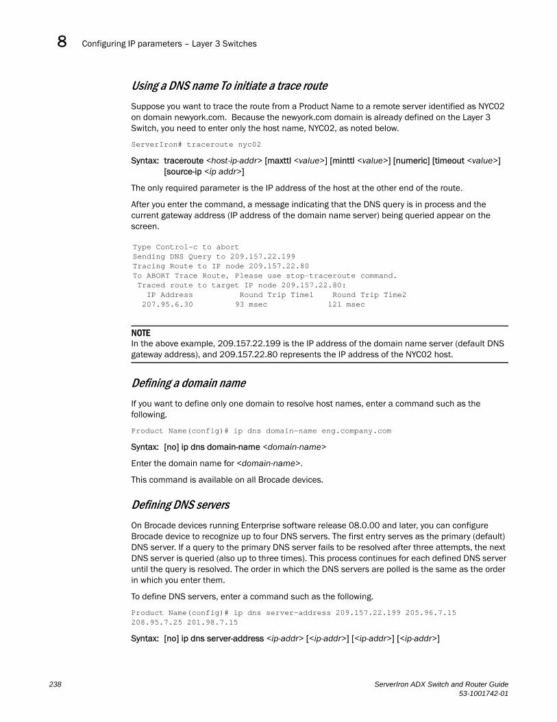
Configuring IP parameters – Layer 3 Switches8DRAFT: BROCADE CONFIDENTIAL
Using a DNS name To initiate a trace route
Suppose you want to trace the route from a Product Name to a remote server identified as NYC02 on domain newyork.com. Because the newyork.com domain is already defined on the Layer 3 Switch, you need to enter only the host name, NYC02, as noted below.
ServerIron# traceroute nyc02
Syntax: traceroute <host-ip-addr> [maxttl <value>] [minttl <value>] [numeric] [timeout <value>] [source-ip <ip addr>]
The only required parameter is the IP address of the host at the other end of the route.
After you enter the command, a message indicating that the DNS query is in process and the current gateway address (IP address of the domain name server) being queried appear on the screen.
NOTEIn the above example, 209.157.22.199 is the IP address of the domain name server (default DNS gateway address), and 209.157.22.80 represents the IP address of the NYC02 host.
Defining a domain name
If you want to define only one domain to resolve host names, enter a command such as the following.
Product Name(config)# ip dns domain-name eng.company.com
Syntax: [no] ip dns domain-name <domain-name>
Enter the domain name for <domain-name>.
This command is available on all Brocade devices.
Defining DNS servers
On Brocade devices running Enterprise software release 08.0.00 and later, you can configure Brocade device to recognize up to four DNS servers. The first entry serves as the primary (default) DNS server. If a query to the primary DNS server fails to be resolved after three attempts, the next DNS server is queried (also up to three times). This process continues for each defined DNS server until the query is resolved. The order in which the DNS servers are polled is the same as the order in which you enter them.
To define DNS servers, enter a command such as the following.
Product Name(config)# ip dns server-address 209.157.22.199 205.96.7.15 208.95.7.25 201.98.7.15
Syntax: [no] ip dns server-address <ip-addr> [<ip-addr>] [<ip-addr>] [<ip-addr>]
Type Control-c to abortSending DNS Query to 209.157.22.199Tracing Route to IP node 209.157.22.80To ABORT Trace Route, Please use stop-traceroute command. Traced route to target IP node 209.157.22.80: IP Address Round Trip Time1 Round Trip Time2 207.95.6.30 93 msec 121 msec
238 ServerIron ADX Switch and Router Guide53-1001742-01
Configuring IP parameters – Layer 3 Switches 8DRAFT: BROCADE CONFIDENTIAL
In the example above, the first DNS server entered becomes the primary DNS server and all others are secondary servers. Because DNS IP address 201.98.7.15 is the last DNS server listed, it is also the last DNS server consulted to resolve a query.
Changing the router IDIn most configurations, a Product Name with router code installed has multiple IP addresses, usually configured on different interfaces. As a result, the Product Name identity to other devices varies depending on the interface to which the other device is attached. Some routing protocols, including Open Shortest Path First (OSPF), identify a Product Name by just one of the IP addresses configured on the Product Name, regardless of the interfaces that connect the Product Namees. This IP address is the router ID.
NOTERouting Information Protocol (RIP) does not use the router ID.
By default, the router ID on a Product Name is one of the following:
• If the router has loopback interfaces, the default router ID is the IP address configured on the lowest numbered loopback interface configured on the Layer 3 Switch. For example, if you configure loopback interfaces 1, 2, and 3 as follows, the default router ID is 9.9.9.9/24:
• Loopback interface 1, 9.9.9.9/24
• Loopback interface 2, 4.4.4.4/24
• Loopback interface 3, 1.1.1.1/24
• If the device does not have any loopback interfaces, the default router ID is the lowest numbered IP interface configured on the device.
If you prefer, you can explicitly set the router ID to any valid IP address. The IP address cannot be in use on another device in the network.
To change the router ID, enter a command such as the following.
ServerIron(config)# ip router-id 209.157.22.26
Syntax: ip router-id <ip-addr>
The <ip-addr> can be any valid, unique IP address.
NOTEYou can specify an IP address used for an interface on the Product Name, but do not specify an IP address in use by another device.
Specifying a single source interface for Telnet, TACACS/TACACS+, or RADIUS packetsWhen the Layer 3 Switch originates a Telnet, TACACS/TACACS+, or RADIUS packet, the source address of the packet is the lowest-numbered IP address on the interface that sends the packet. You can configure the Layer 3 Switch to always the lowest-numbered IP address on a specific interface as the source addresses for these types of packets. When you configure the Layer 3 Switch to use a single source interface for all Telnet, TACACS/TACACS+, or RADIUS packets, the Layer 3 Switch uses the same IP address as the source for all packets of the specified type, regardless of the port(s) that actually sends the packets.
ServerIron ADX Switch and Router Guide 23953-1001742-01

Configuring IP parameters – Layer 3 Switches8DRAFT: BROCADE CONFIDENTIAL
Identifying a single source IP address for Telnet, TACACS/TACACS+, or RADIUS packets provides the following benefits:
• If your Telnet, TACACS/TACACS+, or RADIUS server is configured to accept packets only from specific IP addresses, you can use this feature to simplify configuration of the server by configuring the Brocade device to always send the packets from the same link or source address.
• If you specify a loopback interface as the single source for Telnet, TACACS/TACACS+, or RADIUS packets, servers can receive the packets regardless of the states of individual links. Thus, if a link to the server becomes unavailable but the client or server can be reached through another link, the client or server still receives the packets, and the packets still have the source IP address of the loopback interface.
The software contains separate CLI commands for specifying the source interface for Telnet, TACACS/TACACS+, or RADIUS packets. You can configure a source interface for one or more of these types of packets separately.
To specify an Ethernet or POS port or a loopback or virtual interface as the source for all TACACS/TACACS+ packets from the device, use the following CLI method. The software uses the lowest-numbered IP address configured on the port or interface as the source IP address for TACACS/TACACS+ packets originated by the device.
The following sections show the syntax for specifying a single source IP address for Telnet, TACACS/TACACS+, and RADIUS packets.
Telnet packetsTo specify the lowest-numbered IP address configured on a virtual interface as the device’s source for all Telnet packets, enter commands such as the following.
ServerIron(config)# int loopback 2ServerIron(config-lbif-2)# ip address 10.0.0.2/24ServerIron(config-lbif-2)# exitServerIron(config)# ip telnet source-interface loopback 2
The commands in this example configure loopback interface 2, assign IP address 10.0.0.2/24 to the interface, then designate the interface as the source for all Telnet packets from the Product Name.
Syntax: ip telnet source-interface ethernet <portnum> | loopback <num> | ve <num>
The <num> parameter is a loopback interface or virtual interface number. If you specify an Ethernet port, the <portnum> is the port’s number (including the slot number, if you are configuring a Chassis device).
The following commands configure an IP interface on an Ethernet port and designate the address port as the source for all Telnet packets from the Product Name.
ServerIron(config)# interface ethernet 1/4ServerIron(config-if-1/4)# ip address 209.157.22.110/24ServerIron(config-if-1/4)# exitServerIron(config)# ip telnet source-interface ethernet 1/4
TACACS/TACACS+ packetsTo specify the lowest-numbered IP address configured on a virtual interface as the device’s source for all TACACS/TACACS+ packets, enter commands such as the following.
240 ServerIron ADX Switch and Router Guide53-1001742-01

Configuring IP parameters – Layer 3 Switches 8DRAFT: BROCADE CONFIDENTIAL
ServerIron(config)# int ve 1ServerIron(config-vif-1)# ip address 10.0.0.3/24ServerIron(config-vif-1)# exitServerIron(config)# ip tacacs source-interface ve 1
The commands in this example configure virtual interface 1, assign IP address 10.0.0.3/24 to the interface, then designate the interface as the source for all TACACS/TACACS+ packets from the Product Name.
Syntax: ip tacacs source-interface ethernet <portnum> | loopback <num> | ve <num>
The <num> parameter is a loopback interface or virtual interface number. If you specify an Ethernet port, the <portnum> is the port’s number (including the slot number, if you are configuring a Chassis device).
RADIUS packetsTo specify the lowest-numbered IP address configured on a virtual interface as the device’s source for all RADIUS packets, enter commands such as the following.
ServerIron(config)# int ve 1ServerIron(config-vif-1)# ip address 10.0.0.3/24ServerIron(config-vif-1)# exitServerIron(config)# ip radius source-interface ve 1
The commands in this example configure virtual interface 1, assign IP address 10.0.0.3/24 to the interface, then designate the interface as the source for all RADIUS packets from the Product Name.
Syntax: ip radius source-interface ethernet <portnum> | loopback <num> | ve <num>
The <num> parameter is a loopback interface or virtual interface number. If you specify an Ethernet port, the <portnum> is the port’s number (including the slot number, if you are configuring a Chassis device).
Configuring ARP parametersAddress Resolution Protocol (ARP) is a standard IP protocol that enables an IP Product Name to obtain the MAC address of another device’s interface when the Product Name knows the IP address of the interface. ARP is enabled by default and cannot be disabled.
NOTEProduct Name running router code also supports ARP. The description in “How ARP works” also applies to ARP on Product Name running switch code. However, the configuration options described later in this section apply only to Product Name running router code, not to Product Name running switch code.
How ARP works
A Product Name running router code needs to know a destination’s MAC address when forwarding traffic, because the Product Name running router code encapsulates the IP packet in a Layer 2 packet (MAC layer packet) and sends the Layer 2 packet to a MAC interface on a device directly attached to the Product Name running router code. The device can be the packet’s final destination or the next-hop router toward the destination.
ServerIron ADX Switch and Router Guide 24153-1001742-01

Configuring IP parameters – Layer 3 Switches8DRAFT: BROCADE CONFIDENTIAL
The Product Name running router code encapsulates IP packets in Layer 2 packets regardless of whether the ultimate destination is locally attached or is multiple router hops away. Since the Product Name running router code’s IP route table and IP forwarding cache contain IP address information but not MAC address information, the Product Name running router code cannot forward IP packets based solely on the information in the route table or forwarding cache. The Product Name running router code needs to know the MAC address that corresponds with the IP address of either the packet’s locally attached destination or the next-hop router that leads to the destination.
For example, to forward a packet whose destination is multiple router hops away, the Product Name running router code must send the packet to the next-hop router toward its destination, or to a default route or default network route if the IP route table does not contain a route to the packet’s destination. In each case, the Product Name running router code must encapsulate the packet and address it to the MAC address of a locally attached device, the next-hop router toward the IP packet’s destination.
To obtain the MAC address required for forwarding a datagram, the Layer 3 Switch does the following:
• First, the Product Name running router code looks in the ARP cache (not the static ARP table) for an entry that lists the MAC address for the IP address. The ARP cache maps IP addresses to MAC addresses. The cache also lists the port attached to the device and, if the entry is dynamic, the age of the entry. A dynamic ARP entry enters the cache when the Product Name running router code receives an ARP reply or receives an ARP request (which contains the sender’s IP address and MAC address). A static entry enters the ARP cache from the static ARP table (which is a separate table) when the interface for the entry comes up.
To ensure the accuracy of the ARP cache, each dynamic entry has its own age timer. The timer is reset to zero each time the Product Name running router code receives an ARP reply or ARP request containing the IP address and MAC address of the entry. If a dynamic entry reaches its maximum allowable age, the entry times out and the software removes the entry from the table. Static entries do not age out and can be removed only by you.
• If the ARP cache does not contain an entry for the destination IP address, the Product Name running router code broadcasts an ARP request out all its IP interfaces. The ARP request contains the IP address of the destination. If the device with the IP address is directly attached to the Product Name running router code, the device sends an ARP response containing its MAC address. The response is a unicast packet addressed directly to the Product Name running router code. The Product Name running router code places the information from the ARP response into the ARP cache.
ARP requests contain the IP address and MAC address of the sender, so all devices that receive the request learn the MAC address and IP address of the sender and can update their own ARP caches accordingly.
NOTEIf the router receives an ARP request packet that it is unable to deliver to the final destination because of the ARP timeout and no ARP response is received (the Product Name running router code knows of no route to the destination address), the router sends an ICMP Host Unreachable message to the source.
242 ServerIron ADX Switch and Router Guide53-1001742-01

Configuring IP parameters – Layer 3 Switches 8DRAFT: BROCADE CONFIDENTIAL
Configuring forwarding parametersThe following configurable parameters control the forwarding behavior of a Product Name running router code:
• Time-To-Live (TTL) threshold
• Forwarding of directed broadcasts
• Forwarding of source-routed packets
• Ones-based and zero-based broadcasts
All these parameters are global and thus affect all IP interfaces configured on the Product Name running router code.
To configure these parameters, use the procedures in the following sections.
Changing the TTL threshold
The TTL threshold prevents routing loops by specifying the maximum number of router hops an IP packet originated by the Product Name running router can travel through. Each device capable of forwarding IP that receives the packet decrements (decreases) the packet’s TTL by one. If a device receives a packet with a TTL of 1 and reduces the TTL to zero, the device drops the packet.
The default TTL is 64. You can change the TTL to a value from 1– 255.
To modify the TTL threshold to 25, enter the following commands.
Product Name(config)# ip ttl 25
Syntax: ip ttl <1-255>
Enabling forwarding of directed broadcasts
A directed broadcast is an IP broadcast to all devices within a single directly-attached network or subnet. A net-directed broadcast goes to all devices on a given network. A subnet-directed broadcast goes to all devices within a given subnet.
NOTEA less common type, the all-subnets broadcast, goes to all directly-attached subnets. Forwarding for this broadcast type also is supported, but most networks use IP multicasting instead of all-subnet broadcasting.
Forwarding for all types of IP directed broadcasts is disabled by default. You can enable forwarding for all types if needed. You cannot enable forwarding for specific broadcast types.
To enable forwarding of IP directed broadcasts, use the following method.
ServerIron(config)# ip directed-broadcast
Syntax: [no] ip directed-broadcast
The software makes the forwarding decision based on the router's knowledge of the destination network prefix. Routers cannot determine that a message is unicast or directed broadcast apart from the destination network prefix. The decision to forward or not forward the message is by definition only possible in the last hop router.
To disable the directed broadcasts, enter the following command in the CONFIG mode.
ServerIron(config)# no ip directed-broadcast
ServerIron ADX Switch and Router Guide 24353-1001742-01

Configuring IP parameters – Layer 3 Switches8DRAFT: BROCADE CONFIDENTIAL
To enable directed broadcasts on an individual interface instead of globally for all interfaces, enter commands such as the following.
ServerIron(config)# interface ethernet 1/1ServerIron(config-if-1/1)# ip directed-broadcast
Syntax: [no] ip directed-broadcast
Disabling forwarding of IP source-routed packets
A source-routed packet specifies the exact router path for the packet. The packet specifies the path by listing the IP addresses of the router interfaces through which the packet must pass on its way to the destination. The Product Name running router code supports both types of IP source routing:
• Strict source routing – requires the packet to pass through only the listed routers. If the Product Name running router code receives a strict source-routed packet but cannot reach the next hop interface specified by the packet, the Product Name running router code discards the packet and sends an ICMP Source-Route-Failure message to the sender.
NOTEThe Product Name running router code allows you to disable sending of the Source-Route-Failure messages. Refer to “Disabling ICMP messages” on page 245.
• Loose source routing – requires that the packet pass through all of the listed routers but also allows the packet to travel through other routers, which are not listed in the packet.
The Product Name running router code forwards both types of source-routed packets by default. To disable the feature, use either of the following methods. You cannot enable or disable strict or loose source routing separately.
To disable forwarding of IP source-routed packets, enter the following command.
ServerIron(config)# no ip source-route
Syntax: [no] ip source-route
To re-enable forwarding of source-routed packets, enter the following command.
ServerIron(config)# ip source-route
Enabling support for zero-based IP subnet broadcasts
By default, the Product Name running router code treats IP packets with all ones in the host portion of the address as IP broadcast packets. For example, the Product Name running router code treats IP packets with 209.157.22.255/24 as the destination IP address as IP broadcast packets and forwards the packets to all IP hosts within the 209.157.22.x subnet (except the host that sent the broadcast packet to the Product Name running router code).
Most IP hosts are configured to receive IP subnet broadcast packets with all ones in the host portion of the address. However, some older IP hosts instead expect IP subnet broadcast packets that have all zeros instead of all ones in the host portion of the address. To accommodate this type of host, you can enable the Product Name running router code to treat IP packets with all zeros in the host portion of the destination IP address as broadcast packets.
244 ServerIron ADX Switch and Router Guide53-1001742-01

Configuring IP parameters – Layer 3 Switches 8DRAFT: BROCADE CONFIDENTIAL
NOTEWhen you enable the Product Name running router code for zero-based subnet broadcasts, the Product Name running router code still treats IP packets with all ones the host portion as IP subnet broadcasts too. Thus, the Product Name running router code can be configured to support all ones only (the default) or all ones and all zeroes.
NOTEThis feature applies only to IP subnet broadcasts, not to local network broadcasts. The local network broadcast address is still expected to be all ones.
To enable the Layer 3 Switch for zero-based IP subnet broadcasts in addition to ones-based IP subnet broadcasts, enter the following command.
ServerIron(config)# ip broadcast-zero
Syntax: [no] ip broadcast-zero
Disabling ICMP messagesThe Product Name is enabled to reply to ICMP echo messages and send ICMP Destination Unreachable messages by default.
You can selectively disable the following types of Internet Control Message Protocol (ICMP) messages:
• Echo messages (ping messages) – The Product Name running router code replies to IP pings from other IP devices.
• Destination Unreachable messages – If the Product Name running router code receives an IP packet that it cannot deliver to its destination, the Product Name running router code discards the packet and sends a message back to the device that sent the packet to the Product Name running router code. The message informs the device that the destination cannot be reached by the Product Name running router code.
Disabling replies to broadcast ping requestsBy default, a Product Name running router code is enabled to respond to broadcast ICMP echo packets, which are ping requests. You can disable response to ping requests on a global basis using the following CLI method.
To disable response to broadcast ICMP echo packets (ping requests), enter the following command.
ServerIron(config)# no ip icmp echo broadcast-request
Syntax: [no] ip icmp echo broadcast-request
If you need to re-enable response to ping requests, enter the following command.
ServerIron(config)# ip icmp echo broadcast-request
Disabling ICMP destination unreachable messagesBy default, when a Product Name receives an IP packet that the device cannot deliver, the device sends an ICMP Unreachable message back to the host that sent the packet. You can selectively disable a Product Name response to the following types of ICMP Unreachable messages:
• Administration – The packet was dropped by the Product Name due to a filter or ACL configured on the device.
ServerIron ADX Switch and Router Guide 24553-1001742-01

Configuring IP parameters – Layer 3 Switches8DRAFT: BROCADE CONFIDENTIAL
• Fragmentation-needed – The packet has the Don’t Fragment bit set in the IP Flag field, but the Product Name cannot forward the packet without fragmenting it.
• Host – The destination network or subnet of the packet is directly connected to the Product Name, but the host specified in the destination IP address of the packet is not on the network.
• Network – The Product Name cannot reach the network specified in the destination IP address of the packet.
• Port – The destination host does not have the destination TCP or UDP port specified in the packet. In this case, the host sends the ICMP Port Unreachable message to the Product Name, which in turn sends the message to the host that sent the packet.
• Protocol – The TCP or UDP protocol on the destination host is not running. This message is different from the Port Unreachable message, which indicates that the protocol is running on the host but the requested protocol port is unavailable.
• Source-route-failure – The device received a source-routed packet but cannot locate the next-hop IP address indicated in the packet’s Source-Route option.
You can disable the Product Name from sending these types of ICMP messages on an individual basis. To do so, use the following CLI method.
NOTEDisabling an ICMP Unreachable message type does not change the ability of the Product Name to forward packets. Disabling ICMP Unreachable messages prevents the device from generating or forwarding the Unreachable messages.
To disable all ICMP Unreachable messages, enter the following command.
ServerIron(config)# no ip icmp unreachable
Syntax: [no] ip icmp unreachable [network | host | protocol | administration | fragmentation-needed | port | source-route-fail]
• If you enter the command without specifying a message type (as in the example above), all types of ICMP Unreachable messages listed above are disabled. If you want to disable only specific types of ICMP Unreachable messages, you can specify the message type. To disable more than one type of ICMP message, enter the no ip icmp unreachable command for each messages type.
• The network parameter disables ICMP Network Unreachable messages.
• The host parameter disables ICMP Host Unreachable messages.
• The protocol parameter disables ICMP Protocol Unreachable messages.
• The administration parameter disables ICMP Unreachable (caused by Administration action) messages.
• The fragmentation-needed parameter disables ICMP Fragmentation-Needed But Don’t-Fragment Bit Set messages.
• The port parameter disables ICMP Port Unreachable messages.
• The source-route-fail parameter disables ICMP Unreachable (caused by Source-Route-Failure) messages.
To disable ICMP Host Unreachable messages and ICMP Network Unreachable messages but leave the other types of ICMP Unreachable messages enabled, enter the following commands instead of the command shown above.
246 ServerIron ADX Switch and Router Guide53-1001742-01

Configuring IP parameters – Layer 3 Switches 8DRAFT: BROCADE CONFIDENTIAL
ServerIron(config)# no ip icmp unreachable hostServerIron(config)# no ip icmp unreachable network
If you have disabled all ICMP Unreachable message types but you want to re-enable certain types, you can do so entering commands such as the following.
ServerIron(config)# ip icmp unreachable hostServerIron(config)# ip icmp unreachable network
The commands shown above re-enable ICMP Unreachable Host messages and ICMP Network Unreachable messages.
Disabling ICMP redirect messagesYou can disable or re-enable ICMP redirect messages. By default, a Product Name sends an ICMP redirect message to the source of a misdirected packet in addition to forwarding the packet to the appropriate router. You can disable ICMP redirect messages on a global basis or on an individual port basis.
NOTEThe device forwards misdirected traffic to the appropriate router, even if you disable the redirect messages.
To disable ICMP redirect messages globally, enter the following command at the global CONFIG level of the CLI.
ServerIron(config)# no ip icmp redirects
Syntax: [no] ip icmp redirects
To disable ICMP redirect messages on a specific interface, enter the following command at the configuration level for the interface.
ServerIron(config)# int e 3/11ServerIron(config-if-e100-3/11)# no ip redirect
Syntax: [no] ip redirect
Configuring static routesThe IP route table can receive routes from the following sources:
• Directly-connected networks – When you add an IP interface, the Layer 3 Switch automatically creates a route for the network the interface is in.
• RIP – If RIP is enabled, the Product Name can learn about routes from the advertisements other RIP routers send to the Product Name. If the route has a lower administrative distance than any other routes from different sources to the same destination, the Product Name places the route in the IP route table.
• OSPF – Refer to RIP, but substitute “OSPF” for “RIP”.
• Default network route – A statically configured default route that the Product Name uses if other default routes to the destination are not available. Refer to “Configuring a default network route” on page 256.
• Statically configured route – You can add routes directly to the route table. When you add a route to the IP route table, you are creating a static IP route. This section describes how to add static routes to the IP route table.
ServerIron ADX Switch and Router Guide 24753-1001742-01

Configuring IP parameters – Layer 3 Switches8DRAFT: BROCADE CONFIDENTIAL
Static route types
You can configure the following types of static IP routes:
• Standard – the static route consists of the destination network address and network mask, and the IP address of the next-hop gateway. You can configure multiple standard static routes with the same metric for load sharing or with different metrics to provide a primary route and backup routes.
• Interface-based – the static route consists of the destination network address and network mask, and the Product Name interface through which you want the Product Name to send traffic for the route. Typically, this type of static route is for directly attached destination networks.
• Null – the static route consists of the destination network address and network mask, and the “null0” parameter. Typically, the null route is configured as a backup route for discarding traffic if the primary route is unavailable.
Static IP route parameters
When you configure a static IP route, you must specify the following parameters:
• The IP address and network mask for the route’s destination network.
• The route’s path, which can be one of the following:
• The IP address of a next-hop gateway
• An Ethernet port
• A virtual interface (a routing interface used by VLANs for routing Layer 3 protocol traffic among one another)
• A “null” interface. The Product Name drops traffic forwarded to the null interface.
You also can specify the following optional parameters:
• The route’s metric – The value the Product Name uses when comparing this route to other routes in the IP route table to the same destination. The metric applies only to routes that the Product Name has already placed in the IP route table. The default metric for static IP routes is 1.
• The route’s administrative distance – The value that the Product Name uses to compare this route with routes from other route sources to the same destination before placing a route in the IP route table. This parameter does not apply to routes that are already in the IP route table. The default administrative distance for static IP routes is 1.
The default metric and administrative distance values ensure that the Product Name always prefers static IP routes over routes from other sources to the same destination.
Multiple static routes to the same destination provide load sharing and redundancy
You can add multiple static routes for the same destination network to provide one or more of the following benefits:
• IP load balancing – When you add multiple IP static routes for the same destination to different next-hop gateways, and the routes each have the same metric and administrative distance, the Product Name can load balance traffic to the routes’ destination. For information about IP load balancing, refer to “Configuring IP load sharing” on page 257.
248 ServerIron ADX Switch and Router Guide53-1001742-01

Configuring IP parameters – Layer 3 Switches 8DRAFT: BROCADE CONFIDENTIAL
• Path redundancy – When you add multiple static IP routes for the same destination, but give the routes different metrics or administrative distances, the Product Name uses the route with the lowest administrative distance by default, but uses another route to the same destination of the first route becomes unavailable.
Refer to the following sections for examples and configuration information:
• “Configuring load balancing and redundancy using multiple static routes to the same destination” on page 252
• “Configuring standard static IP routes and interface or null static routes to the same destination” on page 253
Static route states follow port states
IP static routes remain in the IP route table only so long as the port or virtual interface used by the route is available. If the port or virtual routing interface becomes unavailable, the software removes the static route from the IP route table. If the port or virtual routing interface becomes available again later, the software adds the route back to the route table.
This feature allows the Product Name to adjust to changes in network topology. The Product Name does not continue trying to use routes on unavailable paths but instead uses routes only when their paths are available.
Figure 59 shows an example of a network containing a static route. The static route is configured on Router A, as shown in the CLI example following the figure.
FIGURE 59 Example of a static route
The following command configures a static route to 207.95.7.0, using 207.95.6.157 as the next-hop gateway.
ServerIron(config)# ip route 207.95.7.0/24 207.95.6.157
When you configure a static IP route, you specify the destination address for the route and the next-hop gateway or Product Name interface through which the Layer 3 Switch can reach the route. The Product Name adds the route to the IP route table. In this case, Router A knows that 207.95.6.157 is reachable through port 1/2, and also assumes that local interfaces within that subnet are on the same port. Router A deduces that IP interface 207.95.7.188 is also on port 1/2.
The software automatically removes a static IP route from the IP route table if the port used by that route becomes unavailable. When the port becomes available again, the software automatically re-adds the route to the IP route table.
207.95.7.69/24
207.95.7.7/24
Router BRouter A
207.95.6.188/24 207.95.6.157/24e 1/2
ServerIron ADX Switch and Router Guide 24953-1001742-01

Configuring IP parameters – Layer 3 Switches8DRAFT: BROCADE CONFIDENTIAL
Configuring a static IP route
To configure an IP static route with a destination address of 192.0.0.0 255.0.0.0 and a next-hop router IP address of 195.1.1.1, enter the following commands.
ServerIron(config)# ip route 192.0.0.0 255.0.0.0 195.1.1.1
To configure a static IP route with an Ethernet port instead of a next-hop address, enter a command such as the following.
ServerIron(config)# ip route 192.128.2.69 255.255.255.0 ethernet 4/1
The command in the example above configures a static IP route for destination network 192.128.2.69/24. Since an Ethernet port is specified instead of a gateway IP address as the next hop, the Product Name always forwards traffic for the 192.128.2.69/24 network to port 4/1. The command in the following example configures an IP static route that uses virtual interface 3 as its next hop.
ServerIron(config)# ip route 192.128.2.71 255.255.255.0 ve 3
Syntax: ip route <dest-ip-addr> <dest-mask> <next-hop-ip-addr> | ethernet <portnum> | ve <num> [<metric>] [distance <num>]
or
Syntax: ip route <dest-ip-addr>/<mask-bits><next-hop-ip-addr> | ethernet <portnum> | ve <num> [<metric>] [distance <num>]
The <dest-ip-addr> is the route’s destination. The <dest-mask> is the network mask for the route’s destination IP address. Alternatively, you can specify the network mask information by entering a forward slash followed by the number of bits in the network mask. For example, you can enter 192.0.0.0 255.255.255.0 as 192.0.0.0/.24.
The <next-hop-ip-addr> is the IP address of the next-hop router (gateway) for the route.
If you do not want to specify a next-hop IP address, you can instead specify a port or interface number on the Product Name. The <num> parameter is a virtual interface number. If you instead specify an Ethernet port, the <portnum> is the port’s number (including the slot number, if you are configuring a Chassis device). In this case, the Product Name forwards packets destined for the static route’s destination network to the specified interface. Conceptually, this feature makes the destination network like a directly connected network, associated with a specific Product Name interface.
NOTEThe port or virtual interface you use for the static route’s next hop must have at least one IP address configured on it. The address does not need to be in the same subnet as the destination network.
The <metric> parameter can be a number from 1 – 16. The default is 1.
NOTEIf you specify 16, RIP considers the metric to be infinite and thus also considers the route to be unreachable.
250 ServerIron ADX Switch and Router Guide53-1001742-01
Configuring IP parameters – Layer 3 Switches 8DRAFT: BROCADE CONFIDENTIAL
The distance <num> parameter specifies the administrative distance of the route. When comparing otherwise equal routes to a destination, the Product Name prefers lower administrative distances over higher ones, so make sure you use a low value for your default route. The default is 1.
NOTEThe Product Name will replace the static route if the it receives a route with a lower administrative distance.
NOTEYou can also assign the default router as the destination by entering 0.0.0.0 0.0.0.0 xxx.xxx.xxx.xxx.
Configuring a “Null” route
You can configure the Product Name to drop IP packets to a specific network or host address by configuring a “null” (sometimes called “null0”) static route for the address. When the Product Name receives a packet destined for the address, the Product Name drops the packet instead of forwarding it.
To configure a null static route, use the following CLI method.
To configure a null static route to drop packets destined for network 209.157.22.x, enter the following commands.
ServerIron(config)# ip route 209.157.22.0 255.255.255.0 null0ServerIron(config)# write memory
Syntax: ip route <ip-addr> <ip-mask> null0 [<metric>] [distance <num>]
or
Syntax: ip route <ip-addr>/<mask-bits> null0 [<metric>] [distance <num>]
To display the maximum value for your device, enter the show default values command. The maximum number of static IP routes the system can hold is listed in the ip-static-route row in the System Parameters section of the display. To change the maximum value, use the system-max ip-static-route <num> command at the global CONFIG level.
The <ip-addr> parameter specifies the network or host address. The Product Name will drop packets that contain this address in the destination field instead of forwarding them.
The <ip-mask> parameter specifies the network mask. Ones are significant bits and zeros allow any value. For example, the mask 255.255.255.0 matches on all hosts within the Class C subnet address specified by <ip-addr>. Alternatively, you can specify the number of bits in the network mask. For example, you can enter 209.157.22.0/24 instead of 209.157.22.0 255.255.255.0.
The null0 parameter indicates that this is a null route. You must specify this parameter to make this a null route.
The <metric> parameter adds a cost to the route. You can specify from 1 – 16. The default is 1.
The distance <num> parameter configures the administrative distance for the route. You can specify a value from 1 – 255. The default is 1. The value 255 makes the route unusable.
ServerIron ADX Switch and Router Guide 25153-1001742-01

Configuring IP parameters – Layer 3 Switches8DRAFT: BROCADE CONFIDENTIAL
NOTEThe last two parameters are optional and do not affect the null route, unless you configure the administrative distance to be 255. In this case, the route is not used and the traffic might be forwarded instead of dropped.
Configuring load balancing and redundancy using multiple static routes to the same destination
You can configure multiple static IP routes to the same destination, for the following benefits:
• IP load sharing – If you configure more than one static route to the same destination, and the routes have different next-hop gateways but have the same metrics, the Product Name load balances among the routes using basic round-robin. For example, if you configure two static routes with the same metrics but to different gateways, the Product Name alternates between the two routes. For information about IP load balancing, refer to “Configuring IP load sharing” on page 257.
• Backup Routes – If you configure multiple static IP routes to the same destination, but give the routes different next-hop gateways and different metrics, the Product Name will always use the route with the lowest metric. If this route becomes unavailable, the Product Name will fail over to the static route with the next-lowest metric, and so on.
NOTEYou also can bias the Product Name to select one of the routes by configuring them with different administrative distances. However, make sure you do not give a static route a higher administrative distance than other types of routes, unless you want those other types to be preferred over the static route.
The steps for configuring the static routes are the same as described in the previous section. The following sections provide examples.
To configure multiple static IP routes, enter commands such as the following.
ServerIron(config)# ip route 192.128.2.69 255.255.255.0 209.157.22.1ServerIron(config)# ip route 192.128.2.69 255.255.255.0 192.111.10.1
The commands in the example above configure two static IP routes. The routes go to different next-hop gateways but have the same metrics. These commands use the default metric value (1), so the metric is not specified. These static routes are used for load sharing among the next-hop gateways.
The following commands configure static IP routes to the same destination, but with different metrics. The route with the lowest metric is used by default. The other routes are backups in case the first route becomes unavailable. The Product Name uses the route with the lowest metric if the route is available.
ServerIron(config)# ip route 192.128.2.69 255.255.255.0 209.157.22.1ServerIron(config)# ip route 192.128.2.69 255.255.255.0 192.111.10.1 2ServerIron(config)# ip route 192.128.2.69 255.255.255.0 201.1.1.1 3
In this example, each static route has a different metric. The metric is not specified for the first route, so the default (1) is used. A metric is specified for the second and third static IP routes. The second route has a metric of two and the third route has a metric of 3. Thus, the second route is used only of the first route (which has a metric of 1) becomes unavailable. Likewise, the third route is used only if the first and second routes (which have lower metrics) are both unavailable.
252 ServerIron ADX Switch and Router Guide53-1001742-01

Configuring IP parameters – Layer 3 Switches 8DRAFT: BROCADE CONFIDENTIAL
For complete syntax information, refer to “Configuring a static IP route” on page 250.
Configuring standard static IP routes and interface or null static routes to the same destination
You can configure a null0 or interface-based static route to a destination and also configure a normal static route to the same destination, so long as the route metrics are different.
When the Product Name has multiple routes to the same destination, the Product Name always prefers the route with the lowest metric. Generally, when you configure a static route to a destination network, you assign the route a low metric so that the Product Name prefers the static route over other routes to the destination.
This feature is especially useful for the following configurations. These are not the only allowed configurations but they are typical uses of this feature:
• When you want to ensure that if a given destination network is unavailable, the Product Name drops (forwards to the null interface) traffic for that network instead of using alternate paths to route the traffic. In this case, assign the normal static route to the destination network a lower metric than the null route.
• When you want to use a specific interface by default to route traffic to a given destination network, but want to allow the Product Name to use other interfaces to reach the destination network if the path that uses the default interface becomes unavailable. In this case, give the interface route a lower metric than the normal static route.
NOTEYou cannot add a null or interface-based static route to a network if there is already a static route of any type with the same metric you specify for the null or interface-based route.
ServerIron ADX Switch and Router Guide 25353-1001742-01

Configuring IP parameters – Layer 3 Switches8DRAFT: BROCADE CONFIDENTIAL
Figure 60 shows an example of two static routes configured for the same destination network. In this example, one of the routes is a standard static route and has a metric of 1. The other static route is a null route and has a higher metric than the standard static route. The Product Name always prefers the static route with the lower metric. In this example, the Product Name always uses the standard static route for traffic to destination network 192.168.7.0/24, unless that route becomes unavailable, in which case the Product Name sends traffic to the null route instead.
FIGURE 60 Standard and null static routes to the same destination network
X
Two static routes to 192.168.7.0/24:
--Standard static route throughgateway 192.168.6.157, with metric 1
--Null route, with metric 2
Router A Router B
192.168.6.188/24 192.168.6.157/24 192.168.7.7/24
192.168.7.69/24
When standard static routeis good, Router A uses thatroute.
Router A Router B
192.168.6.188/24 192.168.6.157/24 192.168.7.7/24
192.168.7.69/24
If standard static route isunavailable, Router A usesthe null route (in effect droppinginstead of forwarding the packets).
Null
254 ServerIron ADX Switch and Router Guide53-1001742-01

Configuring IP parameters – Layer 3 Switches 8DRAFT: BROCADE CONFIDENTIAL
Figure 61 shows another example of two static routes. In this example, a standard static route and an interface-based static route are configured for destination network 192.168.6.0/24. The interface-based static route has a lower metric than the standard static route. As a result, the Product Name always prefers the interface-based route when the route is available. However, if the interface-based route becomes unavailable, the Product Name still forwards the traffic toward the destination using an alternate route through gateway 192.168.8.11/24.
FIGURE 61 Standard and interface routes to the same destination network
To configure a standard static IP route and a null route to the same network as shown in Figure 60 on page 254, enter commands such as the following.
ServerIron(config)# ip route 192.168.7.0/24 192.168.6.157/24 1ServerIron(config)# ip route 192.168.7.0/24 null0 3
The first command configures a standard static route, which includes specification of the next-hop gateway. The command also gives the standard static route a metric of 1, which causes the Product Name to always prefer this route when the route is available.
The second command configures another static route for the same destination network, but the second route is a null route. The metric for the null route is 3, which is higher than the metric for the standard static route. If the standard static route is unavailable, the software uses the null route.
For complete syntax information, refer to “Configuring a static IP route” on page 250.
To configure a standard static route and an interface-based route to the same destination, enter commands such as the following.
ServerIron(config)# ip route 192.168.6.0/24 ethernet 1/1 1ServerIron(config)# ip route 192.168.6.0/24 192.168.8.11/24 3
Two static routes to 192.168.7.0/24:
--Interface-based route throughport 1/1, with metric 1.
--Standard static route throughgateway 192.168.8.11, with metric 3.
Router A
Router B Router C Router D
192.168.6.69/24
192.168.6.188/24Port 1/1
192.168.8.12/24Port 4/4
192.168.8.11/24
If route through interface1/1 becomes unavailable,Router A uses alternateroute through gateway192.168.8.11/24.
When route through interface1/1 is available, Router A alwaysuses that route.
ServerIron ADX Switch and Router Guide 25553-1001742-01

Configuring IP parameters – Layer 3 Switches8DRAFT: BROCADE CONFIDENTIAL
The first command configured an interface-based static route through Ethernet port 1/1. The command assigns a metric of 1 to this route, causing the Product Name to always prefer this route when it is available. If the route becomes unavailable, the Product Name uses an alternate route through the next-hop gateway 192.168.8.11/24.
Configuring a default network routeThe Product Name enables you to specify a candidate default route without the need to specify the next hop gateway. If the IP route table does not contain an explicit default route (for example, 0.0.0.0/0) or propagate an explicit default route through routing protocols, the software can use the default network route as a default route instead.
When the software uses the default network route, it also uses the default network route's next hop gateway as the gateway of last resort.
This feature is especially useful in environments where network topology changes can make the next hop gateway unreachable. This feature allows the Product Name to perform default routing even if the default network route's default gateway changes.
The feature thus differs from standard default routes. When you configure a standard default route, you also specify the next hop gateway. If a topology change makes the gateway unreachable, the default route becomes unusable.
For example, if you configure 10.10.10.0/24 as a candidate default network route, if the IP route table does not contain an explicit default route (0.0.0.0/0), the software uses the default network route and automatically uses that route's next hop gateway as the default gateway. If a topology change occurs and as a result the default network route's next hop gateway changes, the software can still use the default network route. To configure a default network route, use the following CLI method.
If you configure more than one default network route, the Product Name uses the following algorithm to select one of the routes.
1. Use the route with the lowest administrative distance.
2. If the administrative distances are equal:
• Are the routes from different routing protocols (RIP or OSPF? If so, use the route with the lowest IP address.
• If the routes are from the same routing protocol, use the route with the best metric. The meaning of “best” metric depends on the routing protocol:
• RIP – The metric is the number of hops (additional routers) to the destination. The best route is the route with the fewest hops.
• OSPF – The metric is the path cost associated with the route. The path cost does not indicate the number of hops but is instead a numeric value associated with each route. The best route is the route with the lowest path cost.
Configuring a default network route
To configure a default network route, use one of the following methods. You can configure up to four default network routes.
To configure a default network route, enter commands such as the following.
256 ServerIron ADX Switch and Router Guide53-1001742-01

Configuring IP parameters – Layer 3 Switches 8DRAFT: BROCADE CONFIDENTIAL
ServerIron(config)# ip default-network 209.157.22.0 ServerIron(config)# write memory
Syntax: ip default-network <ip-addr>
The <ip-addr> parameter specifies the network address.
To verify that the route is in the route table, enter the following command at any level of the CLI.
This example shows two routes. Both of the routes are directly attached, as indicated in the Type column. However, one of the routes is shown as type “*D”, with an asterisk (*). The asterisk indicates that this route is a candidate default network route.
Configuring IP load sharingThe IP route table can contain more than one path to a given destination. When this occurs, the Product Name selects the path with the lowest cost as the path for forwarding traffic to the destination. If the IP route table contains more than one path to a destination and the paths each have the lowest cost, then the ServerIron uses IP load sharing to select a path to the destination.1
IP load sharing is based on the destination address of the traffic.
You can enable a Product Name to load balance across up to eight equal-cost paths. The default maximum number of equal-cost load sharing paths is four.
NOTEIP load sharing is not based on source routing, only on next-hop routing.
NOTEThe term “path” refers to the next-hop router to a destination, not to the entire route to a destination. Thus, when the software compares multiple equal-cost paths, the software is comparing paths that use different next-hop routers, with equal costs, to the same destination.
In many contexts, the terms “route” and ”path” mean the same thing. Most of the user documentation uses the term “route” throughout. The term “path” is used in this section to refer to an individual next-hop router to a destination, while the term “route” refers collectively to the multiple paths to the destination. Load sharing applies when the IP route table contains multiple, equal-cost paths to a destination.
How multiple equal-cost paths enter the IP route table
IP load sharing applies to equal-cost paths in the IP route table. Routes that are eligible for load sharing can enter the table from any of the following sources:
• IP static routes
• Routes learned through RIP
1. IP load sharing is also called “Equal-Cost Multi-Path (ECMP)” load sharing or just “ECMP”
ServerIron(config)# show ip routeTotal number of IP routes: 2Start index: 1 B:BGP D:Connected R:RIP S:Static O:OSPF *:Candidate default Destination NetMask Gateway Port Cost Type1 209.157.20.0 255.255.255.0 0.0.0.0 lb1 1 D2 209.157.22.0 255.255.255.0 0.0.0.0 4/11 1 *D
ServerIron ADX Switch and Router Guide 25753-1001742-01
Configuring IP parameters – Layer 3 Switches8DRAFT: BROCADE CONFIDENTIAL
• Routes learned through OSPF
Administrative distanceThe administrative distance is a unique value associated with each type (source) of IP route. Each path has an administrative distance. The administrative distance is not used when performing IP load sharing, but the administrative distance is used when evaluating multiple equal-cost paths to the same destination from different sources, such as RIP, OSPF and so on.
The value of the administrative distance is determined by the source of the route. The Product Name is configured with a unique administrative distance value for each IP route source.
When the software receives multiple paths to the same destination and the paths are from different sources, the software compares the administrative distances of the paths and selects the path with the lowest distance. The software then places the path with the lowest administrative distance in the IP route table. For example, if the Product Name has a path learned from OSPF and a path learned from RIP for a given destination, only the path with the lower administrative distance enters the IP route table.
Here are the default administrative distances on the Product Name:
• Directly connected – 0 (this value is not configurable)
• Static IP route – 1 (applies to all static routes, including default routes and default network routes)
• OSPF – 110
• RIP – 120
• Interior Gateway Protocol (IBGP) – 200
• Local BGP – 200
• Unknown – 255 (the router will not use this route)
Lower administrative distances are preferred over higher distances. For example, if the router receives routes for the same network from OSPF and from RIP, the router will prefer the OSPF route by default.
NOTEYou can change the administrative distances individually. Refer to the configuration chapter for the route source for information.
Since the software selects only the path with the lowest administrative distance, and the administrative distance is determined by the path’s source, IP load sharing does not apply to paths from different route sources. IP load sharing applies only when the IP route table contains multiple paths to the same destination, from the same IP route source.
IP load sharing does not apply to paths that come from different sources.
Path costThe cost parameter provides a common basis of comparison for selecting from among multiple paths to a given destination. Each path in the IP route table has a cost. When the IP route table contains multiple paths to a destination, the Product Name chooses the path with the lowest cost. When the IP route table contains more than one path with the lowest cost to a destination, the Product Name uses IP load sharing to select one of the lowest-cost paths.
The source of a path’s cost value depends on the source of the path.
258 ServerIron ADX Switch and Router Guide53-1001742-01

Configuring IP parameters – Layer 3 Switches 8DRAFT: BROCADE CONFIDENTIAL
• IP static route – The value you assign to the metric parameter when you configure the route. The default metric is 1. Refer to “Configuring load balancing and redundancy using multiple static routes to the same destination” on page 252.
• RIP – The number of next-hop routers to the destination.
• OSPF – The Path Cost associated with the path. The paths can come from any combination of inter-area, intra-area, and external Link State Advertisements (LSAs).
NOTEIf the path is redistributed between two or more of the above sources before entering the IP route table, the cost can increase during the redistribution due to settings in redistribution filters.
Static route and OSPF load sharingIP load sharing and load sharing for static routes and OSPF routes are individually configured. Multiple equal-cost paths for a destination can enter the IP route table only if the source of the paths is configured to support multiple equal-cost paths.
Table 27 lists the default and configurable maximum numbers of paths for each IP route source that can provide equal-cost paths to the IP route table. The table also lists where to find configuration information for the route source’s load sharing parameters.
The load sharing state for all the route sources is based on the state of IP load sharing. Since IP load sharing is enabled by default on all Product Name switches, load sharing for static IP routes, RIP routes and OSPF routes, also is enabled by default.
How IP load sharing works
On the Product Name, IP load sharing is done by the hardware. If there is more than one path to a given destination, a hash is calculated based on the source MAC address, destination MAC address, source IP address, destination IP address, and TCP/UDP source port and destination port if the packet is also a TCP and UDP packet. This hash is used to select one of the paths.
Path redundancyIf a path to a given destination becomes unavailable, the Product Name provides redundancy by using another available equal-cost path to the destination, as described in the following sections.
Response to path state changesIf one of the load-balanced paths to a cached destination becomes unavailable, or the IP route table receives a new equal-cost path to a cached destination, the software removes the unavailable path from the IP route table. Then the software selects a new path:
• For host-based IP load sharing, the next load-balancing cache entry uses the first path to the destination. The first path is the path that entered the IP route table first. “Host-based IP load sharing” on page 260 describes the host-based load-sharing mechanism.
TABLE 27 Default load sharing parameters for route sources
Route source Default number of paths Default maximum number of paths
Maximum number of paths
See page...
Static IP route 4 4 81
1. This value depends on the value for IP load sharing, and is not separately configurable.
page 262
RIP 4 4 81 page 262
OSPF 4 4 81 page 262
ServerIron ADX Switch and Router Guide 25953-1001742-01
Configuring IP parameters – Layer 3 Switches8DRAFT: BROCADE CONFIDENTIAL
• For network-based IP load sharing, the next load-balancing cache entry uses the next available path is then calculated based on the current number of paths and the maximum number of paths allowed.
Host-based IP load sharingThe host-based load sharing method uses a simple round-robin mechanism to select an equal-cost path for traffic to a destination host. When the Product Name receives traffic for a destination host and the IP route table has multiple equal-cost paths to the host, the Product Name checks the IP forwarding cache for a forwarding entry to the destination.
• If the IP forwarding cache contains a forwarding entry for the destination, the device uses the entry to forward the traffic.
• If the IP forwarding cache does not contain a forwarding entry for the destination, the software selects the next path in the rotation (the path after the one the software used for the previous load sharing selection). The software then creates an IP forwarding cache entry that associates the destination host IP address with the selected path (next-hop IP address).
A cache entry for host-based IP load sharing has an age time of ten minutes. If a cache entry is not used before the age time expires, the device deletes the cache entry. The age time for IP load sharing cache entries is not configurable.
260 ServerIron ADX Switch and Router Guide53-1001742-01

Configuring IP parameters – Layer 3 Switches 8DRAFT: BROCADE CONFIDENTIAL
Figure 62 shows an example of host-based IP load sharing. In this example, the Product Name has two equal-cost paths to hosts H1 – H9. For simplicity, this example assumes that the Product Name does not have any entries in its IP forwarding cache to begin with, and receives traffic for the destination hosts (H1 – H9) in ascending numerical order, beginning with H1 and ending with H9.
FIGURE 62 Host-based IP load sharing – basic example
As shown in this example, when the Product Name receives traffic for a destination and the IP route table has multiple equal-cost paths to that destination, the Product Name selects the next equal-cost path (next-hop router) in the rotation and assigns that path to destination. The path rotation is determined by the order in which the IP route table receives the paths.
Since the configuration in this example contains two paths to hosts H1 – H9, the software alternates between the two paths when creating new load sharing cache entries for hosts H1 – H9. So long as the cache entry for a destination remains in the cache, the Product Name always uses the same path for the traffic to the destination. In this example, the Product Name always uses R2 as the next hop for forwarding traffic to H1.
Disabling or re-enabling load sharing
To disable IP load sharing, enter the following commands.
Product Name(config)# no ip load-sharing
Syntax: [no] ip load-sharing
IP Forwarding CacheHost-Based Load Sharing
Destination Host Next-Hop
192.168.1.170 (H1) 192.168.6.2 (R2)
192.168.1.234 (H2) 192.168.5.1 (R3)
192.168.1.218 (H3) 192.168.6.2 (R2)
192.168.2.175 (H4) 192.168.5.1 (R3)
192.168.2.193 (H5) 192.168.6.2 (R2)
192.168.2.155 (H6) 192.168.5.1 (R3)
192.168.3.209 (H7) 192.168.6.2 (R2)
192.168.3.159 (H8) 192.168.5.1 (R3)
192.168.3.111 (H9) 192.168.5.1 (R2)
R1 is configured with four IP loadsharing paths, and has two pathsto hosts H1 - H9, attached to R4.
The cache entries in this exampleare based on the assumption thatR1 receives traffic for hosts in H1 - H9in that order.
Once a packet for host H1 is received,the cache entry applies to all traffic for H1.Thus, R2 is always used.
192.168.6.2 192.168.7.1R2
192.168.6.1
R1
192.168.5.2
192.168.7.2
192.168.4.1
R4
192.168.5.1 192.168.4.2R3
192.168.1.1
192.168.3.1
192.168.2.1
192.168.1.170 192.168.1.234 192.168.1.218
192.168.2.175 192.168.2.193 192.168.2.155
H4 H5 H6
H1 H2 H3
H7 H8 H9
192.168.3.209 192.168.3.159 192.168.3.111
ServerIron ADX Switch and Router Guide 26153-1001742-01

Configuring IP parameters – Layer 3 Switches8DRAFT: BROCADE CONFIDENTIAL
Changing the maximum number of load sharing paths
By default, IP load sharing allows IP traffic to be balanced across up to four equal paths. You can change the maximum number of paths the Product Name supports to a value from 2 – 8.
For optimal results, set the maximum number of paths to a value at least as high as the maximum number of equal-cost paths your network typically contains. For example, if the Product Name you are configuring for IP load sharing has six next-hop routers, set the maximum paths value to six.
NOTEIf the setting for the maximum number of paths is lower than the actual number of equal-cost paths, the software does not use all the paths for load sharing.
To change the number of IP load sharing paths, enter a command such as the following.
ServerIron(config)# ip load-sharing 8
Syntax: [no] ip load-sharing [<num>]
The <num> parameter specifies the number of paths and can be from 2 – 8.
Optimizing the IP forwarding cacheProduct Name uses Content Addressable Memory (CAM) as a fast lookup cache to optimize IP forwarding. The CAM contains an IP route’s destination and the IP address of the next-hop gateway, as well as pointers to packet information in various system buffers. When the Product Name is ready to forward a packet to its destination, the Product Name checks the CAM for a forwarding entry for the packet.
• If the CAM contains an entry, the Product Name uses the entry to forward the packet.
• If the CAM does not contain an entry, the Product Name searches the IP route table for a route to the packet’s destination, then programs an entry into the CAM for the destination and its next-hop gateway. The Product Name uses the CAM entry to forward the next packet to this destination.
By default, the CAM is optimized for environments with a lot of routes to different destination networks. Each CAM entry provides fast-path information for a different destination subnet.
Regardless of whether one of the CAM optimization options described above is enabled, the Product Name uses the IP cache to store forwarding information, then uses the forwarding information in the IP cache to program the CAM. The IP cache can contain host route entries, network route entries, and aggregate entries (aggregate routes of varying prefix lengths or fixed-size portions of the default route). However, regardless of the CAM optimization options, the show ip cache command displays only the host route entries.
Configuring IRDPThe ICMP Router Discovery Protocol (IRDP) is used by Product Name to advertise the IP addresses of its router interfaces to directly attached hosts. IRDP is disabled by default. You can enable the feature on a global basis or on an individual port basis.
• If you enable the feature globally, all ports use the default values for the IRDP parameters.
• If you leave the feature disabled globally but enable it on individual ports, you also can configure the IRDP parameters on an individual port basis.
262 ServerIron ADX Switch and Router Guide53-1001742-01

Configuring IP parameters – Layer 3 Switches 8DRAFT: BROCADE CONFIDENTIAL
NOTEYou can configure IRDP parameters only an individual port basis. To do so, IRDP must be disabled globally and enabled only on individual ports. You cannot configure IRDP parameters if the feature is globally enabled.
When IRDP is enabled, the Product Name periodically sends Router Advertisement messages out the IP interfaces on which the feature is enabled. The messages advertise the IP addresses of the Product Name to directly attached hosts who listen for the messages. In addition, hosts can be configured to query the Product Name for the information by sending Router Solicitation messages.
Some types of hosts use the Router Solicitation messages to discover their default gateway. When IRDP is enabled on the Product Name, it responds to the Router Solicitation messages. Some clients interpret this response to mean that the Product Name is the default gateway. If another router is actually the default gateway for these clients, leave IRDP disabled on the Product Name.
IRDP uses the following parameters. If you enable IRDP on individual ports instead of enabling the feature globally, you can configure these parameters on an individual port basis.
• Packet type – The Product Name can send Router Advertisement messages as IP broadcasts or as IP multicasts addressed to IP multicast group 224.0.0.1. The packet type is IP broadcast.
• Maximum message interval and minimum message interval – When IRDP is enabled, the Product Name sends the Router Advertisement messages every 450 – 600 seconds by default. The time within this interval that the Product Name selects is random for each message and is not affected by traffic loads or other network factors. The random interval minimizes the probability that a host will receive Router Advertisement messages from other routers at the same time. The interval on each IRDP-enabled Product Name interface is independent of the interval on other IRDP-enabled interfaces. The default maximum message interval is 600 seconds. The default minimum message interval is 450 seconds.
• Hold time – Each Router Advertisement message contains a hold time value. This value specifies the maximum amount of time the host should consider an advertisement to be valid until a newer advertisement arrives. When a new advertisement arrives, the hold time is reset. The hold time is always longer than the maximum advertisement interval. Therefore, if the hold time for an advertisement expires, the host can reasonably conclude that the router interface that sent the advertisement is no longer available. The default hold time is three times the maximum message interval.
• Preference – If a host receives multiple Router Advertisement messages from different routers, the host selects the router that sent the message with the highest preference as the default gateway. The preference can be a number from -4294967296 to 4294967295. The default is 0.
Enabling IRDP globally
To globally enable IRDP, enter the following command.
ServerIron(config)# ip irdp
This command enables IRDP on the IP interfaces on all ports. Each port uses the default values for the IRDP parameters. The parameters are not configurable when IRDP is globally enabled.
Enabling IRDP on an individual port
To enable IRDP on an individual interface and change IRDP parameters, enter commands such as the following.
ServerIron ADX Switch and Router Guide 26353-1001742-01

Configuring IP parameters – Layer 3 Switches8DRAFT: BROCADE CONFIDENTIAL
ServerIron(config)# interface ethernet 1/3ServerIron(config-if-1/3)# ip irdp maxadvertinterval 400
This example shows how to enable IRDP on a specific port and change the maximum advertisement interval for Router Advertisement messages to 400 seconds.
NOTETo enable IRDP on individual ports, you must leave the feature globally disabled.
Syntax: [no] ip irdp [broadcast | multicast] [holdtime <seconds>] [maxadvertinterval <seconds>] [minadvertinterval <seconds>] [preference <number>]
The broadcast | multicast parameter specifies the packet type the Layer 3 Switch uses to send Router Advertisement.
• broadcast – The Layer 3 Switch sends Router Advertisement as IP broadcasts. This is the default.
• multicast – The Layer 3 Switch sends Router Advertisement as multicast packets addressed to IP multicast group 224.0.0.1.
The holdtime <seconds> parameter specifies how long a host that receives a Router Advertisement from the Product Name should consider the advertisement to be valid. When a host receives a new Router Advertisement message from the Product Name, the host resets the hold time for the Product Name to the hold time specified in the new advertisement. If the hold time of an advertisement expires, the host discards the advertisement, concluding that the router interface that sent the advertisement is no longer available. The value must be greater than the value of the maxadvertinterval parameter and cannot be greater than 9000. The default is three times the value of the maxadvertinterval parameter.
The maxadvertinterval parameter specifies the maximum amount of time the Product Name waits between sending Router Advertisements. You can specify a value from 1 to the current value of the holdtime parameter. The default is 600 seconds.
The minadvertinterval parameter specifies the minimum amount of time the Product Name can wait between sending Router Advertisements. The default is three-fourths (0.75) the value of the maxadvertinterval parameter. If you change the maxadvertinterval parameter, the software automatically adjusts the minadvertinterval parameter to be three-fourths the new value of the maxadvertinterval parameter. If you want to override the automatically configured value, you can specify an interval from 1 to the current value of the maxadvertinterval parameter.
The preference <number> parameter specifies the IRDP preference level of this Product Name. If a host receives Router Advertisements from multiple routers, the host selects the router interface that sent the message with the highest interval as the host’s default gateway. The valid range is -4294967296 to 4294967295. The default is 0.
Configuring RARPThe Reverse Address Resolution Protocol (RARP) provides a simple mechanism for directly-attached IP hosts to boot over the network. RARP allows an IP host that does not have a means of storing its IP address across power cycles or software reloads to query a directly-attached router for an IP address.
RARP is enabled by default. However, you must create a RARP entry for each host that will use the Product Name for booting. A RARP entry consists of the following information:
• The entry number – the entry’s sequence number in the RARP table.
264 ServerIron ADX Switch and Router Guide53-1001742-01

Configuring IP parameters – Layer 3 Switches 8DRAFT: BROCADE CONFIDENTIAL
• The MAC address of the boot client.
• The IP address you want the Product Name to give to the client.
When a client sends a RARP broadcast requesting an IP address, the Product Name responds to the request by looking in the RARP table for an entry that contains the client’s MAC address:
• If the RARP table contains an entry for the client, the Product Name sends a unicast response to the client that contains the IP address associated with the client’s MAC address in the RARP table.
• If the RARP table does not contain an entry for the client, the Product Name silently discards the RARP request and does not reply to the client.
How RARP differs from BootP/DHCP
RARP and BootP/DHCP are different methods for providing IP addresses to IP hosts when they boot. These methods differ in the following ways:
• Location of configured host addresses:
• RARP requires static configuration of the host IP addresses on the Product Name. The Product Name replies directly to a host’s request by sending an IP address you have configured in the RARP table.
• The Product Name forwards BootP and DHCP requests to a third-party BootP/DHCP server that contains the IP addresses and other host configuration information.
• Connection of host to boot source (Product Name or BootP/DHCP server):
• RARP requires the IP host to be directly attached to the Product Name:
• An IP host and the BootP/DHCP server can be on different networks and on different routers, so long as the routers are configured to forward (“help”) the host’s boot request to the boot server.
• You can centrally configure other host parameters on the BootP/DHCP server, in addition to the IP address, and supply those parameters to the host along with its IP address.
To configure the Layer 3 Switch to forward BootP/DHCP requests when boot clients and the boot servers are on different subnets on different Layer 3 Switch interfaces, refer to “Configuring BootP/DHCP forwarding parameters” on page 269.
Disabling RARP
RARP is enabled by default. To disable RARP, enter the following command at the global CONFIG level.
ServerIron(config)# no ip rarp
Syntax: [no] ip rarp
To re-enable RARP, enter the following command.
ServerIron(config)# ip rarp
Creating static RARP entries
You must configure the RARP entries for the RARP table. The Product Name can send an IP address in reply to a client’s RARP request only if create a RARP entry for that client.
ServerIron ADX Switch and Router Guide 26553-1001742-01

Configuring IP parameters – Layer 3 Switches8DRAFT: BROCADE CONFIDENTIAL
To assign a static IP RARP entry for static routes on a Product Name, enter a command such as the following.
ServerIron(config)# rarp 1 1245.7654.2348 192.53.4.2
This command creates a RARP entry for a client with MAC address 1245.7654.2348. When the Product Name receives a RARP request from this client, the Product Name replies to the request by sending IP address 192.53.4.2 to the client.
Syntax: rarp <number> <mac-addr>.<ip-addr>
The <number> parameter identifies the RARP entry number. You can specify an unused number from 1 to the maximum number of RARP entries supported on the device.
The <mac-addr> parameter specifies the MAC address of the RARP client.
The <ip-addr> parameter specifies the IP address the Product Name will give the client in response to the client’s RARP request.
Changing the maximum number of static RARP entries supported
The number of RARP entries the Product Name supports depends on how much memory the Product Name has. To determine how many RARP entries your Product Name can have, display the system default information using the procedure in the “Displaying and Modifying System Parameter Default Settings” section of the “Configuring Basic Features” chapter of the Brocade Switch and Router Installation and Basic Configuration Guide or the Brocade BigIron Mg8 Switch Installation and Basic Configuration Guide.
If your Product Name allows you to increase the maximum number of RARP entries, you can use a procedure in the same section to do so.
NOTEYou must save the configuration to the startup-config file and reload the software after changing the RARP cache size to place the change into effect.
Configuring UDP broadcast and IP helper parametersSome applications rely on client requests sent as limited IP broadcasts addressed to the UDP’s application port. If a server for the application receives such a broadcast, the server can reply to the client. Routers do not forward subnet directed broadcasts, so the client and server must be on the same network for the broadcast to reach the server. If the client and server are on different networks (on opposite sides of a router), the client’s request cannot reach the server.
You can configure the Product Name to forward clients‘ requests to UDP application servers. To do so:
• Enable forwarding support for the UDP application port, if forwarding support is not already enabled.
• Configure a helper adders on the interface connected to the clients. Specify the helper address to be the IP address of the application server or the subnet directed broadcast address for the IP subnet the server is in. A helper address is associated with a specific interface and applies only to client requests received on that interface. The Layer 3 Switch forwards client requests for any of the application ports the Product Name is enabled to forward to the helper address.
Forwarding support for the following application ports is enabled by default.
266 ServerIron ADX Switch and Router Guide53-1001742-01

Configuring IP parameters – Layer 3 Switches 8DRAFT: BROCADE CONFIDENTIAL
• bootps (port 67)
• dns (port 53)
• tftp (port 69)
• time (port 37)
• netbios-ns (port 137)
• netbios-dgm (port 138)
• tacacs (port 65)
NOTEThe application names are the names for these applications that the Product Name software recognizes, and might not match the names for these applications on some third-party devices. The numbers listed in parentheses are the UDP port numbers for the applications. The numbers come from RFC 1340.
NOTEAs shown above, forwarding support for BootP/DHCP is enabled by default. If you are configuring the Product Name to forward BootP/DHCP requests, refer to “Configuring BootP/DHCP forwarding parameters” on page 269.
You can enable forwarding for other applications by specifying the application port number.
You also can disable forwarding for an application.
NOTEIf you disable forwarding for a UDP application, forwarding of client requests received as broadcasts to helper addresses is disabled. Disabling forwarding of an application does not disable other support for the application. For example, if you disable forwarding of Telnet requests to helper addresses, other Telnet support on the Product Name is not also disabled.
Enabling forwarding for a UDP application
If you want the Product Name to forward client requests for UDP applications that the Product Name does not forward by default, you can enable forwarding support for the port. To enable forwarding support for a UDP application, use either of the following methods. You also can disable forwarding for an application using these methods.
NOTEYou also must configure a helper address on the interface that is connected to the clients for the application. The Product Name cannot forward the requests unless you configure the helper address. Refer to “Configuring an IP helper address” on page 269.
To enable the forwarding of SNMP trap broadcasts, enter the following command.
ServerIron(config)# ip forward-protocol udp snmp-trap
Syntax: [no] ip forward-protocol udp <udp-port-name> | <udp-port-num>
The <udp-port-name> parameter can have one of the following values. For reference, the corresponding port numbers from RFC 1340 are shown in parentheses. If you specify an application name, enter the name only, not the parentheses or the port number shown here:
• bootpc (port 68)
ServerIron ADX Switch and Router Guide 26753-1001742-01

Configuring IP parameters – Layer 3 Switches8DRAFT: BROCADE CONFIDENTIAL
• bootps (port 67)
• discard (port 9)
• dns (port 53)
• dnsix (port 90)
• echo (port 7)
• mobile-ip (port 434)
• netbios-dgm (port 138)
• netbios-ns (port 137)
• ntp (port 123)
• tacacs (port 65)
• talk (port 517)
• time (port 37)
• tftp (port 69)
In addition, you can specify any UDP application by using the application’s UDP port number.
The <udp-port-num> parameter specifies the UDP application port number. If the application you want to enable is not listed above, enter the application port number. You also can list the port number for any of the applications listed above.
To disable forwarding for an application, enter a command such as the following.
ServerIron(config)# no ip forward-protocol udp snmp
This command disables forwarding of SNMP requests to the helper addresses configured on Product Name interfaces.
Configuring an IP helper address
To forward a client’s broadcast request for a UDP application when the client and server are on different networks, you must configure a helper address on the interface connected to the client. Specify the server’s IP address or the subnet directed broadcast address of the IP subnet the server is in as the helper address.
You can configure up to 16 helper addresses on each interface. You can configure a helper address on an Ethernet port or a virtual interface. To configure a helper address, use the following method.
To configure a helper address on interface 2 on chassis module 1, enter the following commands.
ServerIron(config)# interface e 1/2ServerIron(config-if-1/2)# ip helper-address 1 207.95.7.6
The commands in this example change the CLI to the configuration level for port 1/2, then add a helper address for server 207.95.7.6 to the port. If the port receives a client request for any of the applications that the Product Name is enabled to forward, the Product Name forwards the client’s request to the server.
Syntax: ip helper-address <num> <ip-addr>
The <num> parameter specifies the helper address number and can be from 1 – 16.
The <ip-addr> command specifies the server’s IP address or the subnet directed broadcast address of the IP subnet the server is in.
268 ServerIron ADX Switch and Router Guide53-1001742-01
Configuring IP parameters – Layer 3 Switches 8DRAFT: BROCADE CONFIDENTIAL
Configuring BootP/DHCP forwarding parametersA host on an IP network can use BootP/DHCP to obtain its IP address from a BootP/DHCP server. To obtain the address, the client sends a BootP/DHCP request. The request is a subnet directed broadcast and is addressed to UDP port 67. A limited IP broadcast is addressed to IP address 255.255.255.255 and is not forwarded by the Product Name or other IP routers.
When the BootP/DHCP client and server are on the same network, the server receives the broadcast request and replies to the client. However, when the client and server are on different networks, the server does not receive the client’s request, because the Product Name does not forward the request.
You can configure the Product Name to forward BootP/DHCP requests. To do so, configure a helper address on the interface that receives the client requests, and specify the BootP/DHCP server’s IP address as the address you are helping the BootP/DHCP requests to reach. Instead of the server’s IP address, you can specify the subnet directed broadcast address of the IP subnet the server is in.
BootP/DHCP forwarding parameters
The following parameters control the forwarding of BootP/DHCP requests for a Product Name:
• Helper address – The BootP/DHCP server’s IP address. You must configure the helper address on the interface that receives the BootP/DHCP requests from the client. The Product Name cannot forward a request to the server unless you configure a helper address for the server.
• Gateway address – The Product Name places the IP address of the interface that received the BootP/DHCP request in the request packet’s Gateway Address field (sometimes called the Router ID field). When the server responds to the request, the server sends the response as a unicast packet to the IP address in the Gateway Address field. (If the client and server are directly attached, the Gateway ID field is empty and the server replies to the client using a unicast or broadcast packet, depending on the server.)
By default, the Product Name uses the lowest-numbered IP address on the interface that receives the request as the Gateway address. You can override the default by specifying the IP address you want the Product Name to use.
• Hop Count – Each router that forwards a BootP/DHCP packet increments the hop count by 1. Routers also discard a forwarded BootP/DHCP request instead of forwarding the request if the hop count is greater than the maximum number of BootP/DHCP hops allows by the router. By default, a Product Name forwards a BootP/DHCP request if its hop count is four or less, but discards the request if the hop count is greater than four. You can change the maximum number of hops the Product Name will allow to a value from 1 – 15.
NOTEThe BootP/DHCP hop count is not the TTL parameter.
Configuring an IP helper address
The procedure for configuring a helper address for BootP/DHCP requests is the same as the procedure for configuring a helper address for other types of UDP broadcasts. Refer to “Configuring an IP helper address” on page 268.
ServerIron ADX Switch and Router Guide 26953-1001742-01
Configuring IP parameters – Layer 2 Switches8DRAFT: BROCADE CONFIDENTIAL
Changing the IP address used for stamping BootP/DHCP requests
When the Product Name forwards a BootP/DHCP request, the Product Name “stamps” the Gateway Address field. The default value the Product Name uses to stamp the packet is the lowest-numbered IP address configured on the interface that received the request. If you want the Product Name to use a different IP address to stamp requests received on the interface, use either of the following methods to specify the address.
The BootP/DHCP stamp address is an interface parameter. Change the parameter on the interface that is connected to the BootP/DHCP client.
To change the IP address used for stamping BootP/DHCP requests received on interface 1/1, enter commands such as the following.
ServerIron(config)# int e 1/1ServerIron(config-if-1/1)# ip bootp-gateway 109.157.22.26
These commands change the CLI to the configuration level for port 1/1, then change the BootP/DHCP stamp address for requests received on port 1/1 to 192.157.22.26. The Layer 3 Switch will place this IP address in the Gateway Address field of BootP/DHCP requests that the Product Name receives on port 1/1 and forwards to the BootP/DHCP server.
Syntax: ip bootp-gateway <ip-addr>
Changing the maximum number of hops to a BootP relay server
Each BootP/DHCP request includes a field Hop Count field. The Hop Count field indicates how many routers the request has passed through. When the Product Name receives a BootP/DHCP request, the Product Name looks at the value in the Hop Count field.
• If the hop count value is equal to or less than the maximum hop count the Product Name allows, the Product Name increments the hop count by one and forwards the request.
• If the hop count is greater than the maximum hop count the Product Name allows, the Product Name discards the request.
To change the maximum number of hops the Product Name allows for forwarded BootP/DHCP requests, use the following method.
NOTEThe BootP/DHCP hop count is not the TTL parameter.
To modify the maximum number of BootP/DHCP hops, enter the following command.
ServerIron(config)# bootp-relay-max-hops 10
This command allows the Product Name to forward BootP/DHCP requests that have passed through up to ten previous hops before reaching the Product Name.
Syntax: bootp-relay-max-hops <1-15>
Configuring IP parameters – Layer 2 SwitchesThe following sections describe how to configure IP parameters on a Product Name.
270 ServerIron ADX Switch and Router Guide53-1001742-01

Configuring IP parameters – Layer 2 Switches 8DRAFT: BROCADE CONFIDENTIAL
NOTEThis section describes how to configure IP parameters for a Product Name running switch code. For IP configuration information for a Product Name running router code, refer to “Configuring IP parameters – Layer 3 Switches” on page 231.
Configuring the management IP address and specifying the default gatewayTo manage a Product Name running switch code using Telnet or Secure Shell (SSH) CLI connections or the Web management interface, you must configure an IP address for the Product Name. Optionally, you also can specify the default gateway.
The Product Name supports both classical IP network masks (Class A, B, and C subnet masks, and so on) and Classless Interdomain Routing (CIDR) network prefix masks.
• To enter a classical network mask, enter the mask in IP address format. For example, enter “209.157.22.99 255.255.255.0” for an IP address with a Class-C subnet mask.
• To enter a prefix network mask, enter a forward slash ( / ) and the number of bits in the mask immediately after the IP address. For example, enter “209.157.22.99/24” for an IP address that has a network mask with 24 significant bits (ones).
By default, the CLI displays network masks in classical IP address format (example: 255.255.255.0). You can change the display to prefix format. Refer to “Changing the network mask display to prefix format” on page 277.
To configure an IP address and specify the default gateway, use the following CLI method.
To assign an IP address to a Product Name, enter a command such as the following at the global CONFIG level.
ServerIron(config)# ip address 192.45.6.110 255.255.255.0
Syntax: ip address <ip-addr> <ip-mask>
or
Syntax: ip address <ip-addr>/<mask-bits>
NOTEYou also can enter the IP address and mask in CIDR format, as follows.ServerIron(config)# ip address 192.45.6.1/24
To specify the default gateway of the Product Name, enter a command such as the following.
ServerIron(config)# ip default-gateway 192.45.6.1 255.255.255.0
Syntax: ip default-gateway <ip-addr>
or
Syntax: ip default-gateway <ip-addr>/<mask-bits>
ServerIron ADX Switch and Router Guide 27153-1001742-01

Configuring IP parameters – Layer 2 Switches8DRAFT: BROCADE CONFIDENTIAL
Configuring Domain Name Server (DNS) resolverThe Domain Name Server (DNS) resolver feature lets you use a host name to perform Telnet, ping, and traceroute commands. You can also define a DNS domain on a Product Name and thereby recognize all hosts within that domain. After you define a domain name, the Product Name automatically appends the appropriate domain to the host and forwards it to the domain name server.
For example, if the domain “newyork.com” is defined on a Product Name and you want to initiate a ping to host “NYC01” on that domain, you need to reference only the host name in the command instead of the host name and its domain name. For example, you could enter either of the following commands to initiate the ping.
ServerIron# ping nyc01ServerIron# ping nyc01.newyork.com
Defining a DNS entry
You can define up to four DNS servers for each DNS entry. The first entry serves as the primary default address. If a query to the primary address fails to be resolved after three attempts, the next gateway address is queried (also up to three times). This process continues for each defined gateway address until the query is resolved. The order in which the default gateway addresses are polled is the same as the order in which you enter them.
Suppose you want to define the domain name of newyork.com on a Product Name and then define four possible default DNS gateway addresses. To do so, enter the following commands.
ServerIron(config)# ip dns domain-name newyork.comServerIron(config)# ip dns server-address 209.157.22.199 205.96.7.15 208.95.7.25 201.98.7.15
Syntax: ip dns server-address <ip-addr> [<ip-addr>] [<ip-addr>] [<ip-addr>]
In this example, the first IP address in the ip dns server-address... command becomes the primary gateway address and all others are secondary addresses. Because IP address 201.98.7.15 is the last address listed, it is also the last address consulted to resolve a query.
Using a DNS name to initiate a trace routeExample
Suppose you want to trace the route from a Product Name to a remote server identified as NYC02 on domain newyork.com. Because the newyork.com domain is already defined on the Product Name, you need to enter only the host name, NYC02, as noted below.
ServerIron# traceroute nyc02
Syntax: traceroute <host-ip-addr> [maxttl <value>] [minttl <value>] [numeric] [timeout <value>] [source-ip <ip addr>]
The only required parameter is the IP address of the host at the other end of the route.
After you enter the command, a message indicating that the DNS query is in process and the current gateway address (IP address of the domain name server) being queried appear on the screen.
272 ServerIron ADX Switch and Router Guide53-1001742-01

Configuring IP parameters – Layer 2 Switches 8DRAFT: BROCADE CONFIDENTIAL
NOTEIn the above example, 209.157.22.199 is the IP address of the domain name server (default DNS gateway address), and 209.157.22.80 represents the IP address of the NYC02 host.
FIGURE 63 Querying a host on the newyork.com domain
Changing the TTL thresholdThe TTL threshold prevents routing loops by specifying the maximum number of router hops an IP packet originated by the Product Name can travel through. Each device capable of forwarding IP that receives the packet decrements (decreases) the packet’s TTL by one. If a router receives a packet with a TTL of 1 and reduces the TTL to zero, the router drops the packet.
The default TTL is 64. You can change the TTL to a value from 1 – 255.
To modify the TTL, use the following CLI method.
To modify the TTL threshold to 25, enter the following commands.
ServerIron(config)# ip ttl 25ServerIron(config)# exit
Syntax: ip ttl <1-255>
Type Control-c to abortSending DNS Query to 209.157.22.199Tracing Route to IP node 209.157.22.80To ABORT Trace Route, Please use stop-traceroute command. Traced route to target IP node 209.157.22.80: IP Address Round Trip Time1 Round Trip Time2 207.95.6.30 93 msec 121 msec
...
...
[
ServerIron
Domain Name Server
nyc02
nyc01
nyc01nyc02
207.95.6.199
newyork.com
ServerIron ADX Switch and Router Guide 27353-1001742-01
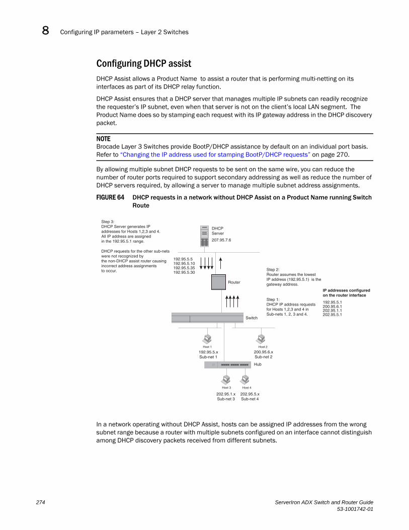
Configuring IP parameters – Layer 2 Switches8DRAFT: BROCADE CONFIDENTIAL
Configuring DHCP assistDHCP Assist allows a Product Name to assist a router that is performing multi-netting on its interfaces as part of its DHCP relay function.
DHCP Assist ensures that a DHCP server that manages multiple IP subnets can readily recognize the requester’s IP subnet, even when that server is not on the client’s local LAN segment. The Product Name does so by stamping each request with its IP gateway address in the DHCP discovery packet.
NOTEBrocade Layer 3 Switches provide BootP/DHCP assistance by default on an individual port basis. Refer to “Changing the IP address used for stamping BootP/DHCP requests” on page 270.
By allowing multiple subnet DHCP requests to be sent on the same wire, you can reduce the number of router ports required to support secondary addressing as well as reduce the number of DHCP servers required, by allowing a server to manage multiple subnet address assignments.
FIGURE 64 DHCP requests in a network without DHCP Assist on a Product Name running Switch Route
In a network operating without DHCP Assist, hosts can be assigned IP addresses from the wrong subnet range because a router with multiple subnets configured on an interface cannot distinguish among DHCP discovery packets received from different subnets.
Step 3:DHCP Server generates IPaddresses for Hosts 1,2,3 and 4.All IP address are assignedin the 192.95.5.1 range.
DHCP requests for the other sub-netswere not recognized bythe non-DHCP assist router causingincorrect address assignmentsto occur.
DHCPServer
207.95.7.6
192.95.5.35
192.95.5.5
192.95.5.30
192.95.5.10
Router
Switch
Host 1 Host 2
Host 3 Host 4
192.95.5.xSub-net 1
200.95.6.xSub-net 2
202.95.1.xSub-net 3
202.95.5.xSub-net 4
Hub
Step 1:DHCP IP address requestsfor Hosts 1,2,3 and 4 inSub-nets 1, 2, 3 and 4.
Step 2:Router assumes the lowestIP address (192.95.5.1) is thegateway address.
192.95.5.1200.95.6.1202.95.1.1202.95.5.1
IP addresses configuredon the router interface
274 ServerIron ADX Switch and Router Guide53-1001742-01

Configuring IP parameters – Layer 2 Switches 8DRAFT: BROCADE CONFIDENTIAL
For example, in Figure 64 a host from each of the four subnets supported on a Product Name requests an IP address from the DHCP server. These requests are sent transparently to the router. Because the router is unable to determine the origin of each packet by subnet, it assumes the lowest IP address or the ‘primary address’ is the gateway for all ports on the Product Name and stamps the request with that address.
When the DHCP request is received at the server, it assigns all IP addresses within that range only.
With DHCP Assist enabled on a Product Name, correct assignments are made because the Product Name provides the stamping service.
How DHCP assist works
Upon initiation of a DHCP session, the client sends out a DHCP discovery packet for an address from the DHCP server as seen in Figure 65. When the DHCP discovery packet is received at a Product Name with the DHCP Assist feature enabled, the gateway address configured on the receiving interface is inserted into the packet. This address insertion is also referred to as stamping.
FIGURE 65 DHCP requests in a network with DHCP Assist operating
DHCPServer
207.95.7.6
Router
Host 1 Host 2
Host 3 Host 4
192.95.5.xSub-net 1
200.95.6.xSub-net 2
202.95.1.xSub-net 3
202.95.5.xSub-net 4
Interface 2 Interface 14
Interface 8
Step 1:DHCP IP address requestsfor Hosts 1,2,3 and 4 inSub-nets 1, 2, 3 and 4.
Gateway addresses:192.95.5.1200.95.6.1202.95.1.1202.95.5.1
Step 2:ServerIron stamps each DHCP requestwith the gateway address of thecorresponding subnet of thereceiving port.
Step 3:Router forwards the DHCP request to theserver without touching the gatewayaddress inserted in the packet by the switch.
ServerIron ADX Switch and Router Guide 27553-1001742-01
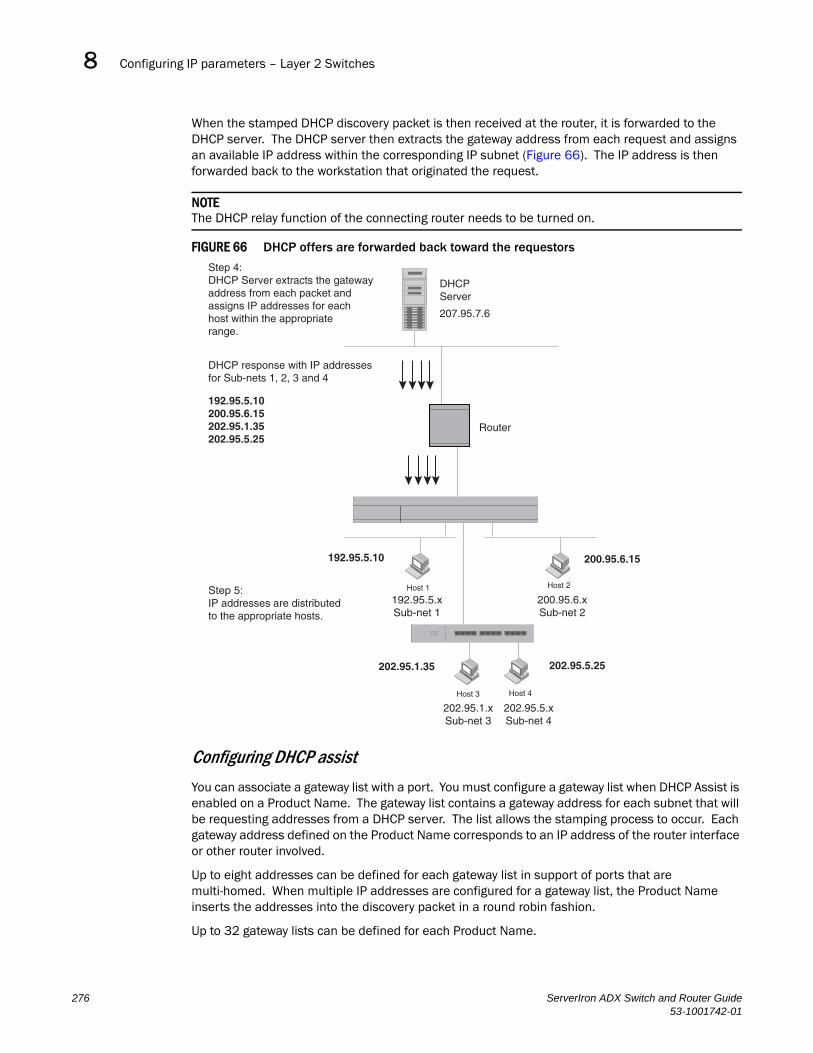
Configuring IP parameters – Layer 2 Switches8DRAFT: BROCADE CONFIDENTIAL
When the stamped DHCP discovery packet is then received at the router, it is forwarded to the DHCP server. The DHCP server then extracts the gateway address from each request and assigns an available IP address within the corresponding IP subnet (Figure 66). The IP address is then forwarded back to the workstation that originated the request.
NOTEThe DHCP relay function of the connecting router needs to be turned on.
FIGURE 66 DHCP offers are forwarded back toward the requestors
Configuring DHCP assist
You can associate a gateway list with a port. You must configure a gateway list when DHCP Assist is enabled on a Product Name. The gateway list contains a gateway address for each subnet that will be requesting addresses from a DHCP server. The list allows the stamping process to occur. Each gateway address defined on the Product Name corresponds to an IP address of the router interface or other router involved.
Up to eight addresses can be defined for each gateway list in support of ports that are multi-homed. When multiple IP addresses are configured for a gateway list, the Product Name inserts the addresses into the discovery packet in a round robin fashion.
Up to 32 gateway lists can be defined for each Product Name.
Step 4:DHCP Server extracts the gatewayaddress from each packet andassigns IP addresses for eachhost within the appropriaterange.
DHCP response with IP addressesfor Sub-nets 1, 2, 3 and 4
Step 5:IP addresses are distributedto the appropriate hosts.
192.95.5.10 200.95.6.15
202.95.1.35 202.95.5.25
Host 1 Host 2
192.95.5.xSub-net 1
200.95.6.xSub-net 2
Host 3 Host 4
202.95.1.xSub-net 3
202.95.5.xSub-net 4
Router
DHCPServer
207.95.7.6
192.95.5.10200.95.6.15202.95.1.35202.95.5.25
276 ServerIron ADX Switch and Router Guide53-1001742-01

Displaying IP configuration information and statistics 8DRAFT: BROCADE CONFIDENTIAL
Example
To create the configuration indicated in Figure 65 and Figure 66, enter the following commands.
ServerIron(config)# dhcp-gateway-list 1 192.95.5.1ServerIron(config)# dhcp-gateway-list 2 200.95.6.1ServerIron(config)# dhcp-gateway-list 3 202.95.1.1 202.95.5.1ServerIron(config)# int e 2ServerIron(config-if-2)# dhcp-gateway-list 1ServerIron(config-if-2)# int e8ServerIron(config-if-8)# dhcp-gateway-list 3ServerIron(config-if-8)# int e 14ServerIron(config-if-14)# dhcp-gateway-list 2
Syntax: dhcp-gateway-list <num> <ip-addr>
Displaying IP configuration information and statisticsThe following sections describe IP display options for Layer 3 Switches and Layer 2 Switches:
• To display IP information on a Product Name running router code, refer to “Displaying IP information – Product Name running router code” on page 278.
• To display IP information on a Product Name running switch code, refer to “Displaying IP information – Product Name running switch code” on page 293.
Changing the network mask display to prefix formatBy default, the CLI displays network masks in classical IP address format (example: 255.255.255.0). You can change the displays to prefix format using the following CLI method.
To enable CIDR format for displaying network masks, entering the following command at the global CONFIG level of the CLI.
ServerIron(config)# ip show-subnet-length
Syntax: [no] ip show-subnet-length
Displaying information for jumbo packets
The output of the show interfaces ethernet and show statistics ethernet command displays information about the number of packets received that were longer than 1518 octets. In the following examples, this output is highlighted in bold.
ServerIron ADX Switch and Router Guide 27753-1001742-01

Displaying IP configuration information and statistics8DRAFT: BROCADE CONFIDENTIAL
Syntax: show statistics ethernet
Displaying IP information – Product Name running router codeYou can display the following IP configuration information statistics on a Product Name:
• Global IP parameter settings and IP access policies – refer to “Displaying global IP configuration information” on page 279.
• CPU utilization statistics – refer to “Displaying CPU utilization statistics” on page 280.
• IP interfaces – refer to “Displaying IP interface information” on page 282.
Product Name# show interfaces ethernet e 1/1FastEthernet1/1 is up, line protocol is up Hardware is FastEthernet, address is 0004.8085.c500 (bia 0004.8085.c500) Configured speed auto, actual 100Mbit, configured duplex fdx, actual fdx Member of L2 VLAN ID 1, port is untagged, port state is FORWARDING STP configured to ON, priority is level0, flow control enabled mirror disabled, monitor disabled Not member of any active trunks Not member of any configured trunks No port name Internet address is 10.1.1.4/24, MTU 1518 bytes, encapsulation ethernet 300 second input rate: 0 bits/sec, 0 packets/sec, 0.00% utilization 300 second output rate: 0 bits/sec, 0 packets/sec, 0.00% utilization 0 packets input, 0 bytes, 0 no buffer Received 0 broadcasts, 0 multicasts, 0 unicasts 0 input errors, 0 CRC, 0 frame, 0 ignored 0 filtered, 0 runts, 0 giants, DMA received 0 packets, 0 jumbos 4 packets output, 256 bytes, 0 underruns Transmitted 4 broadcasts, 0 multicasts, 0 unicasts 0 output errors, 0 collisions, DMA transmitted 4 packets, 0 jumbos
Product Name# show statistics ethernet e 1/25Port Link State Dupl Speed Trunk Tag Priori MAC Name1/1 Up Forward Full 100M None No level0 0004.8085.c500
Port 1/1 Counters: InOctets 0 OutOctets 256 InPkts 0 OutPkts 4 DMA recvd 0 DMA xmited 4 InBroadcastPkts 0 OutBroadcastPkts 4 InMulticastPkts 0 OutMulticastPkts 0 InUnicastPkts 0 OutUnicastPkts 0 InJumboPkts 0 OutJumboPkts 0 InDiscards 0 OutDiscards 0 InErrors 0 OutErrors 0 InCollisions 0 OutCollisions 0 OutLateCollisions 0 Alignment 0 FCS 0 GiantPkts 0 ShortPkts 0 InBitsPerSec 0 OutBitsPerSec 0 InPktsPerSec 0 OutPktsPerSec 0 InUtilization 0.00% OutUtilization 0.00
278 ServerIron ADX Switch and Router Guide53-1001742-01

Displaying IP configuration information and statistics 8DRAFT: BROCADE CONFIDENTIAL
• ARP entries – refer to “Displaying ARP entries” on page 284.
• Static ARP entries – refer to “Displaying ARP entries” on page 284.
• IP forwarding cache – refer to “Displaying the forwarding cache” on page 286.
• IP route table – refer to “Displaying the IP route table” on page 287.
• IP traffic statistics – refer to “Displaying IP traffic statistics” on page 290.
The sections below describe how to display this information.
Displaying global IP configuration information
To display global IP configuration information for the router, use one of the following methods.
Using the CLITo display IP configuration information, enter the following command at any CLI level.
Syntax: show ip
NOTEThis command has additional options, which are explained in other sections in this guide, including the sections below this one.
This display shows the following information.
TABLE 28 CLI display of global IP configuration information – Layer 3 Switch
This field... Displays...
Global settings
ttl The Time-To-Live (TTL) for IP packets. The TTL specifies the maximum number of router hops a packet can travel before reaching the Brocade router. If the packet’s TTL value is higher than the value specified in this field, the Brocade router drops the packet. To change the maximum TTL, refer to “Changing the TTL threshold” on page 243.
arp-age The ARP aging period. This parameter specifies how many minutes an inactive ARP entry remains in the ARP cache before the router ages out the entry.
Product Name> show ip
Global Settings ttl: 64, arp-age: 10, bootp-relay-max-hops: 4 router-id : 207.95.11.128 enabled : UDP-Broadcast-Forwarding IRDP Proxy-ARP RARP OSPF disabled: BGP4 Load-Sharing RIP DVMRP FSRP VRRPStatic Routes Index IP Address Subnet Mask Next Hop Router Metric Distance 1 0.0.0.0 0.0.0.0 209.157.23.2 1 1Policies Index Action Source Destination Protocol Port Operator 1 deny 209.157.22.34 209.157.22.26 tcp http = 64 permit any any
ServerIron ADX Switch and Router Guide 27953-1001742-01

Displaying IP configuration information and statistics8DRAFT: BROCADE CONFIDENTIAL
Displaying CPU utilization statistics
You can display CPU utilization statistics for IP protocols using the show process cpu command.
The show process cpu command includes CPU utilization statistics for ACL, NAT, 802.1x, and L2VLAN. L2VLAN contains any packet transmitted to a VLAN by the CPU, including unknown unicast, multicast, broadcast, and CPU forwarded Layer 2 traffic.
To display CPU utilization statistics for the previous one-second, one-minute, five-minute, and fifteen-minute intervals, enter the following command at any level of the CLI.
bootp-relay-max-hops The maximum number of hops away a BootP server can be located from the Brocade router and still be used by the router’s clients for network booting.To change this value, refer to “Changing the maximum number of hops to a BootP relay server” on page 270.
router-id The 32-bit number that uniquely identifies the Brocade router. By default, the router ID is the numerically lowest IP interface configured on the router. To change the router ID, refer to “Changing the router ID” on page 239.
enabled The IP-related protocols that are enabled on the router.
disabled The IP-related protocols that are disabled on the router.
Static routes
Index The row number of this entry in the IP route table.
IP Address The IP address of the route’s destination.
Subnet Mask The network mask for the IP address.
Next Hop Router The IP address of the router interface to which the Brocade router sends packets for the route.
Metric The cost of the route. Usually, the metric represents the number of hops to the destination.
Distance The administrative distance of the route. The default administrative distance for static IP routes in Brocade routers is 1.
Index The policy number. This is the number you assigned the policy when you configured it.
TABLE 28 CLI display of global IP configuration information – Layer 3 Switch (Continued)
This field... Displays...
280 ServerIron ADX Switch and Router Guide53-1001742-01

Displaying IP configuration information and statistics 8DRAFT: BROCADE CONFIDENTIAL
If the software has been running less than 15 minutes (the maximum interval for utilization statistics), the command indicates how long the software has been running. Here is an example:
To display utilization statistics for a specific number of seconds, enter a command such as the following.
ServerIron# show process cpuProcess Name 5Sec(%) 1Min(%) 5Min(%) 15Min(%) Runtime(ms)ACL 0.00 0.00 0.00 0.00 0ARP 0.01 0.01 0.01 0.01 714BGP 0.00 0.00 0.00 0.00 0DOT1X 0.00 0.00 0.00 0.00 0GVRP 0.00 0.00 0.00 0.00 0ICMP 0.00 0.00 0.00 0.00 161IP 0.00 0.00 0.00 0.00 229L2VLAN 0.01 0.00 0.00 0.01 673NAT 0.00 0.00 0.00 0.00 0OSPF 0.00 0.00 0.00 0.00 0RIP 0.00 0.00 0.00 0.00 9STP 0.00 0.00 0.00 0.00 7VRRP 0.00 0.00 0.00 0.00 0
ServerIron# show process cpuThe system has only been up for 6 seconds.Process Name 5Sec(%) 1Min(%) 5Min(%) 15Min(%) Runtime(ms)ACL 0.00 0.00 0.00 0.00 0ARP 0.01 0.01 0.01 0.01 714BGP 0.00 0.00 0.00 0.00 0DOT1X 0.00 0.00 0.00 0.00 0GVRP 0.00 0.00 0.00 0.00 0ICMP 0.00 0.00 0.00 0.00 161IP 0.00 0.00 0.00 0.00 229L2VLAN 0.01 0.00 0.00 0.01 673NAT 0.00 0.00 0.00 0.00 0OSPF 0.00 0.00 0.00 0.00 0RIP 0.00 0.00 0.00 0.00 9STP 0.00 0.00 0.00 0.00 7VRRP 0.00 0.00 0.00 0.00 0
ServerIron# show process cpu 2Statistics for last 1 sec and 80 msProcess Name Sec(%) Time(ms)ACL 0 0.00ARP 1 0.01BGP 0 0.00DOT1X 0 0.00GVRP 0 0.00ICMP 0 0.00IP 0 0.00L2VLAN 1 0.01NAT 0 0.00OSPF 0 0.00RIP 0 0.00STP 0 0.00VRRP 0 0.00
ServerIron ADX Switch and Router Guide 28153-1001742-01

Displaying IP configuration information and statistics8DRAFT: BROCADE CONFIDENTIAL
When you specify how many seconds’ worth of statistics you want to display, the software selects the sample that most closely matches the number of seconds you specified. In this example, statistics are requested for the previous two seconds. The closest sample available is actually for the previous 1 second plus 80 milliseconds.
Syntax: show process cpu [<num>]
The <num> parameter specifies the number of seconds and can be from 1 – 900. If you use this parameter, the command lists the usage statistics only for the specified number of seconds. If you do not use this parameter, the command lists the usage statistics for the previous one-second, one-minute, five-minute, and fifteen-minute intervals.
Displaying IP interface information
To display IP interface information, enter the following command at any CLI level.
Syntax: show ip interface [ethernet <portnum>] | [loopback <num>] | [ve <num>]
This display shows the following information.
To display detailed IP information for a specific interface, enter a command such as the following.
TABLE 29 CLI display of interface IP configuration information
This field... Displays...
Interface The type and the slot and port number of the interface.
IP-Address The IP address of the interface.
NOTE: If an “s” is listed following the address, this is a secondary address. When the address was configured, the interface already had an IP address in the same subnet, so the software required the “secondary” option before the software could add the interface.
OK? Whether the IP address has been configured on the interface.
Method Whether the IP address has been saved in NVRAM. If you have set the IP address for the interface in the CLI or Web Management interface, but have not saved the configuration, the entry for the interface in the Method field is “manual”.
Status The link status of the interface. If you have disabled the interface with the disable command, the entry in the Status field will be “administratively down”. Otherwise, the entry in the Status field will be either “up” or “down”.
Protocol Whether the interface can provide two-way communication. If the IP address is configured, and the link status of the interface is up, the entry in the protocol field will be “up”. Otherwise the entry in the protocol field will be “down”.
ServerIron(config)# show ip interface
Interface IP-Address OK? Method Status ProtocolEthernet 1/1 207.95.6.173 YES NVRAM up upEthernet 1/2 3.3.3.3 YES manual up upLoopback 1 1.2.3.4 YES NVRAM down down
282 ServerIron ADX Switch and Router Guide53-1001742-01
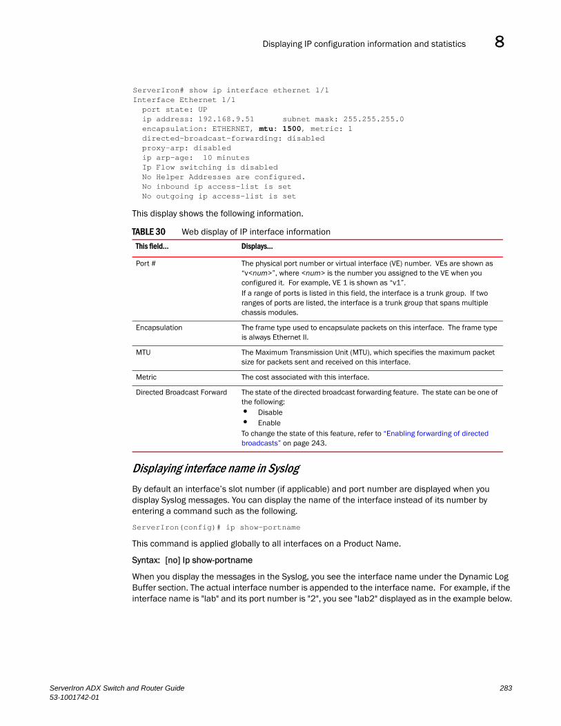
Displaying IP configuration information and statistics 8DRAFT: BROCADE CONFIDENTIAL
This display shows the following information.
Displaying interface name in Syslog
By default an interface’s slot number (if applicable) and port number are displayed when you display Syslog messages. You can display the name of the interface instead of its number by entering a command such as the following.
ServerIron(config)# ip show-portname
This command is applied globally to all interfaces on a Product Name.
Syntax: [no] Ip show-portname
When you display the messages in the Syslog, you see the interface name under the Dynamic Log Buffer section. The actual interface number is appended to the interface name. For example, if the interface name is "lab" and its port number is "2", you see "lab2" displayed as in the example below.
TABLE 30 Web display of IP interface information
This field... Displays...
Port # The physical port number or virtual interface (VE) number. VEs are shown as “v<num>”, where <num> is the number you assigned to the VE when you configured it. For example, VE 1 is shown as “v1”. If a range of ports is listed in this field, the interface is a trunk group. If two ranges of ports are listed, the interface is a trunk group that spans multiple chassis modules.
Encapsulation The frame type used to encapsulate packets on this interface. The frame type is always Ethernet II.
MTU The Maximum Transmission Unit (MTU), which specifies the maximum packet size for packets sent and received on this interface.
Metric The cost associated with this interface.
Directed Broadcast Forward The state of the directed broadcast forwarding feature. The state can be one of the following:• Disable• Enable To change the state of this feature, refer to “Enabling forwarding of directed broadcasts” on page 243.
ServerIron# show ip interface ethernet 1/1Interface Ethernet 1/1 port state: UP ip address: 192.168.9.51 subnet mask: 255.255.255.0 encapsulation: ETHERNET, mtu: 1500, metric: 1 directed-broadcast-forwarding: disabled proxy-arp: disabled ip arp-age: 10 minutes Ip Flow switching is disabled No Helper Addresses are configured. No inbound ip access-list is set No outgoing ip access-list is set
ServerIron ADX Switch and Router Guide 28353-1001742-01
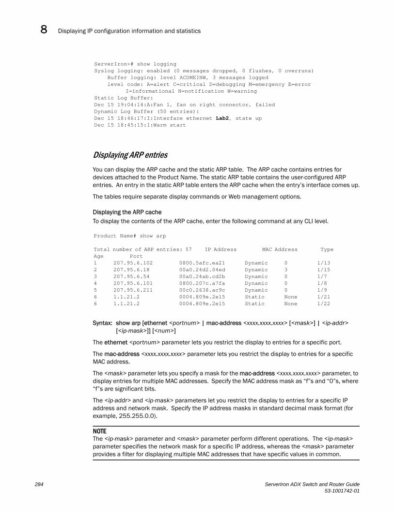
Displaying IP configuration information and statistics8DRAFT: BROCADE CONFIDENTIAL
Displaying ARP entries
You can display the ARP cache and the static ARP table. The ARP cache contains entries for devices attached to the Product Name. The static ARP table contains the user-configured ARP entries. An entry in the static ARP table enters the ARP cache when the entry’s interface comes up.
The tables require separate display commands or Web management options.
Displaying the ARP cacheTo display the contents of the ARP cache, enter the following command at any CLI level.
Syntax: show arp [ethernet <portnum> | mac-address <xxxx.xxxx.xxxx> [<mask>] | <ip-addr> [<ip-mask>]] [<num>]
The ethernet <portnum> parameter lets you restrict the display to entries for a specific port.
The mac-address <xxxx.xxxx.xxxx> parameter lets you restrict the display to entries for a specific MAC address.
The <mask> parameter lets you specify a mask for the mac-address <xxxx.xxxx.xxxx> parameter, to display entries for multiple MAC addresses. Specify the MAC address mask as “f”s and “0”s, where “f”s are significant bits.
The <ip-addr> and <ip-mask> parameters let you restrict the display to entries for a specific IP address and network mask. Specify the IP address masks in standard decimal mask format (for example, 255.255.0.0).
NOTEThe <ip-mask> parameter and <mask> parameter perform different operations. The <ip-mask> parameter specifies the network mask for a specific IP address, whereas the <mask> parameter provides a filter for displaying multiple MAC addresses that have specific values in common.
ServerIron># show loggingSyslog logging: enabled (0 messages dropped, 0 flushes, 0 overruns) Buffer logging: level ACDMEINW, 3 messages logged level code: A=alert C=critical D=debugging M=emergency E=error
I=informational N=notification W=warningStatic Log Buffer:Dec 15 19:04:14:A:Fan 1, fan on right connector, failedDynamic Log Buffer (50 entries):Dec 15 18:46:17:I:Interface ethernet Lab2, state upDec 15 18:45:15:I:Warm start
Product Name# show arp
Total number of ARP entries: 57 IP Address MAC Address Type Age Port1 207.95.6.102 0800.5afc.ea21 Dynamic 0 1/132 207.95.6.18 00a0.24d2.04ed Dynamic 3 1/153 207.95.6.54 00a0.24ab.cd2b Dynamic 0 1/74 207.95.6.101 0800.207c.a7fa Dynamic 0 1/85 207.95.6.211 00c0.2638.ac9c Dynamic 0 1/96 1.1.21.2 0004.809e.2e15 Static None 1/216 1.1.21.2 0004.809e.2e15 Static None 1/22
284 ServerIron ADX Switch and Router Guide53-1001742-01

Displaying IP configuration information and statistics 8DRAFT: BROCADE CONFIDENTIAL
The <num> parameter lets you display the table beginning with a specific entry number.
NOTEThe entry numbers in the ARP cache are not related to the entry numbers for static ARP table entries.
This display shows the following information. The number in the left column of the CLI display is the row number of the entry in the ARP cache. This number is not related to the number you assign to static MAC entries in the static ARP table.
Displaying the static ARP tableTo display the static ARP table instead of the ARP cache, enter the following command at any CLI level.
This example shows two static entries. Note that since you specify an entry’s index number when you create the entry, it is possible for the range of index numbers to have gaps, as shown in this example.
NOTEThe entry number you assign to a static ARP entry is not related to the entry numbers in the ARP cache.
Syntax: show ip static-arp [ethernet <portnum> | mac-address <xxxx.xxxx.xxxx> [<mask>] | <ip-addr> [<ip-mask>]] [<num>]
The ethernet <portnum> parameter lets you restrict the display to entries for a specific port.
The mac-address <xxxx.xxxx.xxxx> parameter lets you restrict the display to entries for a specific MAC address.
TABLE 31 CLI display of ARP cache
This field... Displays...
(route number) ID of the entry. If multiple outgoing ports for a static route are configured, there will be more than one entry for that route as in route #6 above.
IP Address The IP address of the device.
MAC Address The MAC address of the device.
Type The type, which can be one of the following:• Dynamic – The Product Name learned the entry from an incoming packet.• Static – The Product Name loaded the entry from the static ARP table
when the device for the entry was connected to the Product Name.
Age The number of minutes the entry has remained unused. If this value reaches the ARP aging period, the entry is removed from the table. To display the ARP aging period, refer to “Displaying global IP configuration information” on page 279.
NOTE: Static entries do not age out.
Port The port on which the entry was learned.
ServerIron# show ip static-arp
Static ARP table size: 512, configurable from 512 to 1024 Index IP Address MAC Address Port 1 207.95.6.111 0800.093b.d210 1/1 3 207.95.6.123 0800.093b.d211 1/1
ServerIron ADX Switch and Router Guide 28553-1001742-01

Displaying IP configuration information and statistics8DRAFT: BROCADE CONFIDENTIAL
The <mask> parameter lets you specify a mask for the mac-address <xxxx.xxxx.xxxx> parameter, to display entries for multiple MAC addresses. Specify the MAC address mask as “f”s and “0”s, where “f”s are significant bits.
The <ip-addr> and <ip-mask> parameters let you restrict the display to entries for a specific IP address and network mask. Specify the IP address masks in standard decimal mask format (for example, 255.255.0.0).
NOTEThe <ip-mask> parameter and <mask> parameter perform different operations. The <ip-mask> parameter specifies the network mask for a specific IP address, whereas the <mask> parameter provides a filter for displaying multiple MAC addresses that have specific values in common.
The <num> parameter lets you display the table beginning with a specific entry number.
Displaying the forwarding cache
To display the IP forwarding cache, enter the following command at any CLI level.
Syntax: show ip cache [<ip-addr>] | [<num>]
The <ip-addr> parameter displays the cache entry for the specified IP address.
The <num> parameter displays the cache beginning with the row following the number you enter. For example, to begin displaying the cache at row 10, enter the following command: show ip cache 9.
The show ip cache command displays the following information.
TABLE 32 CLI display of static ARP table
This field... Displays...
Static ARP table size The maximum number of static entries that can be configured on the device using the current memory allocation. The range of valid memory allocations for static ARP entries is listed after the current allocation.
Index The number of this entry in the table. You specify the entry number when you create the entry.
IP Address The IP address of the device.
MAC Address The MAC address of the device.
Port The port attached to the device the entry is for.
ServerIron> show ip cache
Total number of cache entries: 3D:Dynamic P:Permanent F:Forward U:Us C:Complex FilterW:Wait ARP I:ICMP Deny K:Drop R:Fragment S:Snap Encap IP Address Next Hop MAC Type Port Vlan Pri1 192.168.1.11 DIRECT 0000.0000.0000 PU n/a 02 192.168.1.255 DIRECT 0000.0000.0000 PU n/a 03 255.255.255.255 DIRECT 0000.0000.0000 PU n/a 0
286 ServerIron ADX Switch and Router Guide53-1001742-01

Displaying IP configuration information and statistics 8DRAFT: BROCADE CONFIDENTIAL
Displaying the IP route table
To display the IP route table, enter the following command at any CLI level.
Syntax: show ip route [<ip-addr> [<ip-mask>] [longer] | <num> | direct | ospf | rip | static | summary ]
The <ip-addr> parameter displays the route to the specified IP address.
TABLE 33 CLI display of IP forwarding cache – Layer 3 Switch
This field... Displays...
IP Address The IP address of the destination.
Next Hop The IP address of the next-hop router to the destination. This field contains either an IP address or the value DIRECT. DIRECT means the destination is either directly attached or the destination is an address on this Brocade device. For example, the next hop for loopback addresses and broadcast addresses is shown as DIRECT.
MAC The MAC address of the destination.
NOTE: If the entry is type U (indicating that the destination is this Brocade device), the address consists of zeroes.
Type The type of host entry, which can be one or more of the following:• D – Dynamic• P – Permanent• F – Forward• U – Us• C – Complex Filter• W – Wait ARP• I – ICMP Deny• K – Drop• R – Fragment• S – Snap Encap
Port The port through which this device reaches the destination. For destinations that are located on this device, the port number is shown as “n/a”.
VLAN Indicates the VLAN(s) the listed port is in.
ServerIron> show ip routeTotal number of IP routes: 514Start index: 1 B:BGP D:Connected R:RIP S:Static O:OSPF *:Candidate default Destination NetMask Gateway Port Cost Type1 1.1.0.0 255.255.0.0 99.1.1.2 1/1 2 R2 1.2.0.0 255.255.0.0 99.1.1.2 1/1 2 R3 1.3.0.0 255.255.0.0 99.1.1.2 1/1 2 R4 1.4.0.0 255.255.0.0 99.1.1.2 1/1 2 R5 1.5.0.0 255.255.0.0 99.1.1.2 1/1 2 R6 1.6.0.0 255.255.0.0 99.1.1.2 1/1 2 R7 1.7.0.0 255.255.0.0 99.1.1.2 1/1 2 R8 1.8.0.0 255.255.0.0 99.1.1.2 1/1 2 R9 1.9.0.0 255.255.0.0 99.1.1.2 1/1 2 R10 1.10.0.0 255.255.0.0 99.1.1.2 1/1 2 S11 200.200.200.2 255.255.255.255 0.0.0.0 1/21 1 SA
ServerIron ADX Switch and Router Guide 28753-1001742-01
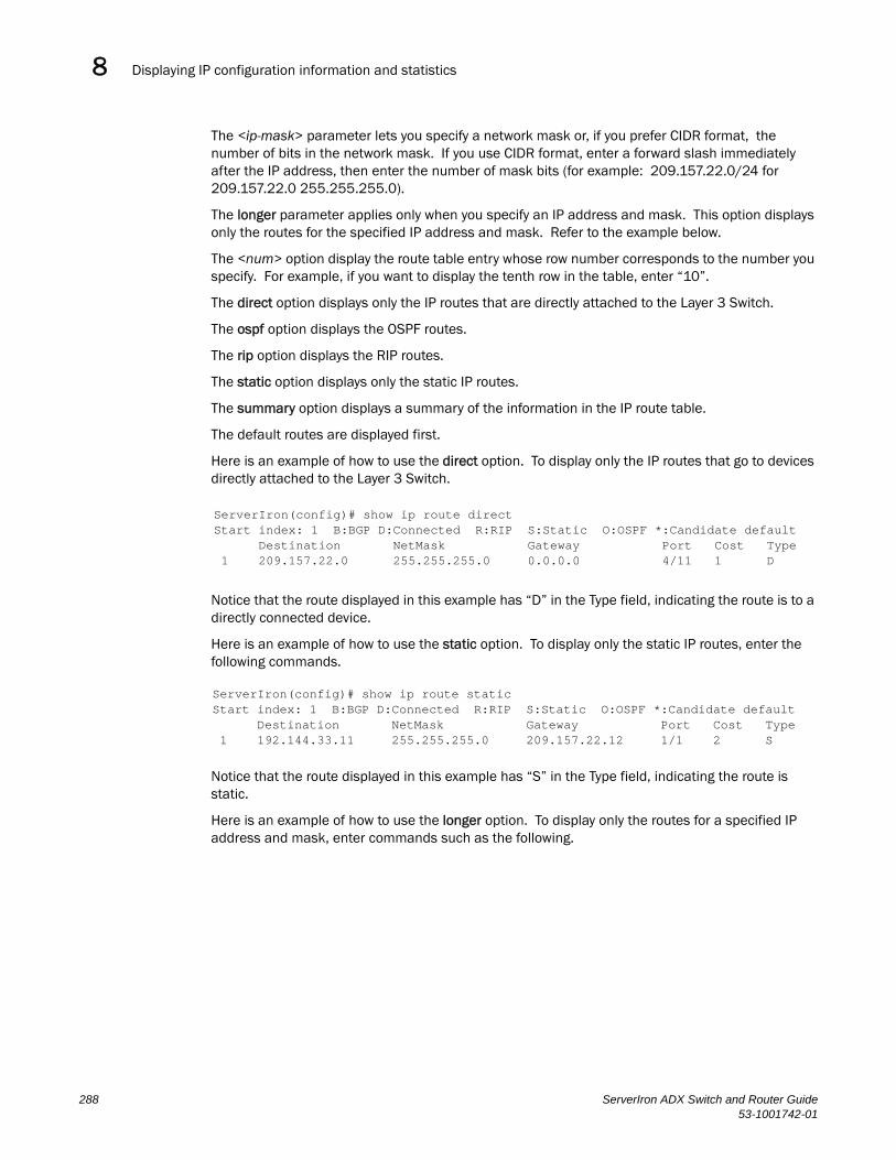
Displaying IP configuration information and statistics8DRAFT: BROCADE CONFIDENTIAL
The <ip-mask> parameter lets you specify a network mask or, if you prefer CIDR format, the number of bits in the network mask. If you use CIDR format, enter a forward slash immediately after the IP address, then enter the number of mask bits (for example: 209.157.22.0/24 for 209.157.22.0 255.255.255.0).
The longer parameter applies only when you specify an IP address and mask. This option displays only the routes for the specified IP address and mask. Refer to the example below.
The <num> option display the route table entry whose row number corresponds to the number you specify. For example, if you want to display the tenth row in the table, enter “10”.
The direct option displays only the IP routes that are directly attached to the Layer 3 Switch.
The ospf option displays the OSPF routes.
The rip option displays the RIP routes.
The static option displays only the static IP routes.
The summary option displays a summary of the information in the IP route table.
The default routes are displayed first.
Here is an example of how to use the direct option. To display only the IP routes that go to devices directly attached to the Layer 3 Switch.
Notice that the route displayed in this example has “D” in the Type field, indicating the route is to a directly connected device.
Here is an example of how to use the static option. To display only the static IP routes, enter the following commands.
Notice that the route displayed in this example has “S” in the Type field, indicating the route is static.
Here is an example of how to use the longer option. To display only the routes for a specified IP address and mask, enter commands such as the following.
ServerIron(config)# show ip route directStart index: 1 B:BGP D:Connected R:RIP S:Static O:OSPF *:Candidate default Destination NetMask Gateway Port Cost Type 1 209.157.22.0 255.255.255.0 0.0.0.0 4/11 1 D
ServerIron(config)# show ip route staticStart index: 1 B:BGP D:Connected R:RIP S:Static O:OSPF *:Candidate default Destination NetMask Gateway Port Cost Type 1 192.144.33.11 255.255.255.0 209.157.22.12 1/1 2 S
288 ServerIron ADX Switch and Router Guide53-1001742-01

Displaying IP configuration information and statistics 8DRAFT: BROCADE CONFIDENTIAL
This example shows all the routes for networks beginning with 209.159. The mask value and longer parameter specify the range of network addresses to be displayed. In this example, all routes within the range 209.159.0.0 – 209.159.255.255 are listed.
The summary option displays a summary of the information in the IP route table. The following is an example of the output from this command.
ServerIron# show ip route summary
IP Routing Table - 35 entries: 6 connected, 28 static, 0 RIP, 1 OSPF, 0 BGP, 0 ISIS, 0 MPLS Number of prefixes: /0: 1 /16: 27 /22: 1 /24: 5 /32: 1
Syntax: show ip route summary
In this example, the IP route table contains 35 entries. Of these entries, 6 are directly connected devices, 28 are static routes, and 1 route was calculated through OSPF. One of the routes has a zero-bit mask (this is the default route), 27 have a 22-bit mask, 5 have a 24-bit mask, and 1 has a 32-bit mask.
The following table lists the information displayed by the show ip route command.
TABLE 34 CLI display of IP route table
This field... Displays...
Destination The destination network of the route.
NetMask The network mask of the destination address.
Gateway The next-hop router.
Port The port through which this router sends packets to reach the route's destination.
ServerIron(config)# show ip route 209.159.0.0/16 longerStarting index: 1 B:BGP D:Directly-Connected R:RIP S:Static O:OSPFDestination NetMask Gateway Port Cost Type
52 209.159.38.0 255.255.255.0 207.95.6.101 1/1 1 S53 209.159.39.0 255.255.255.0 207.95.6.101 1/1 1 S54 209.159.40.0 255.255.255.0 207.95.6.101 1/1 1 S55 209.159.41.0 255.255.255.0 207.95.6.101 1/1 1 S56 209.159.42.0 255.255.255.0 207.95.6.101 1/1 1 S57 209.159.43.0 255.255.255.0 207.95.6.101 1/1 1 S58 209.159.44.0 255.255.255.0 207.95.6.101 1/1 1 S59 209.159.45.0 255.255.255.0 207.95.6.101 1/1 1 S60 209.159.46.0 255.255.255.0 207.95.6.101 1/1 1 S
ServerIron ADX Switch and Router Guide 28953-1001742-01
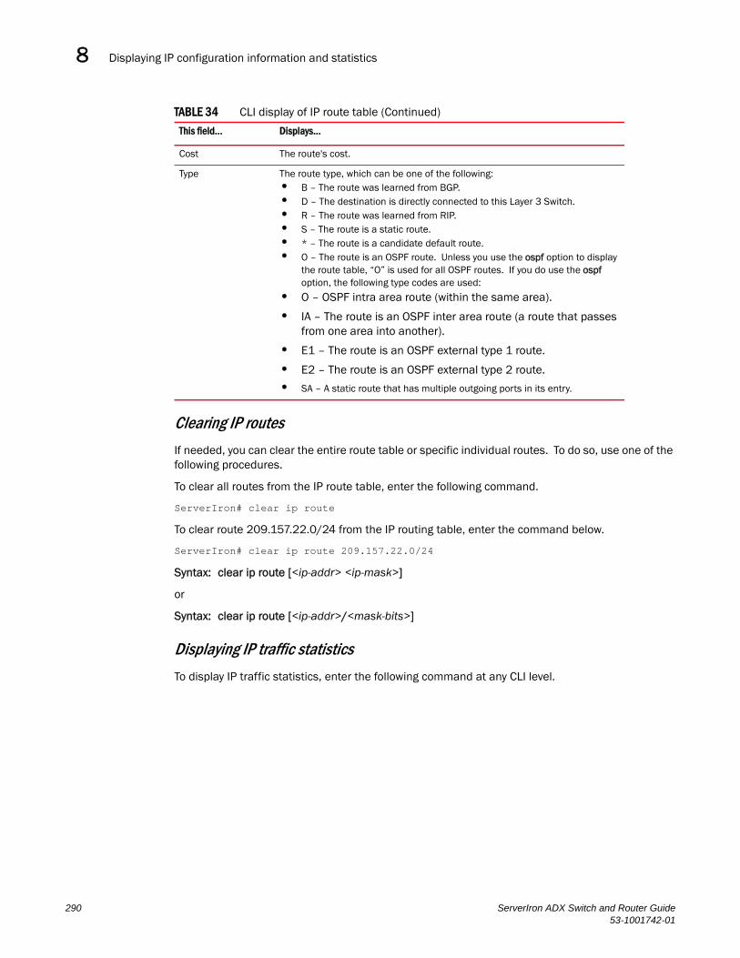
Displaying IP configuration information and statistics8DRAFT: BROCADE CONFIDENTIAL
Clearing IP routes
If needed, you can clear the entire route table or specific individual routes. To do so, use one of the following procedures.
To clear all routes from the IP route table, enter the following command.
ServerIron# clear ip route
To clear route 209.157.22.0/24 from the IP routing table, enter the command below.
ServerIron# clear ip route 209.157.22.0/24
Syntax: clear ip route [<ip-addr> <ip-mask>]
or
Syntax: clear ip route [<ip-addr>/<mask-bits>]
Displaying IP traffic statistics
To display IP traffic statistics, enter the following command at any CLI level.
Cost The route's cost.
Type The route type, which can be one of the following:• B – The route was learned from BGP.• D – The destination is directly connected to this Layer 3 Switch. • R – The route was learned from RIP.• S – The route is a static route.• * – The route is a candidate default route.• O – The route is an OSPF route. Unless you use the ospf option to display
the route table, “O” is used for all OSPF routes. If you do use the ospf option, the following type codes are used:
• O – OSPF intra area route (within the same area).
• IA – The route is an OSPF inter area route (a route that passes from one area into another).
• E1 – The route is an OSPF external type 1 route.
• E2 – The route is an OSPF external type 2 route.
• SA – A static route that has multiple outgoing ports in its entry.
TABLE 34 CLI display of IP route table (Continued)
This field... Displays...
290 ServerIron ADX Switch and Router Guide53-1001742-01
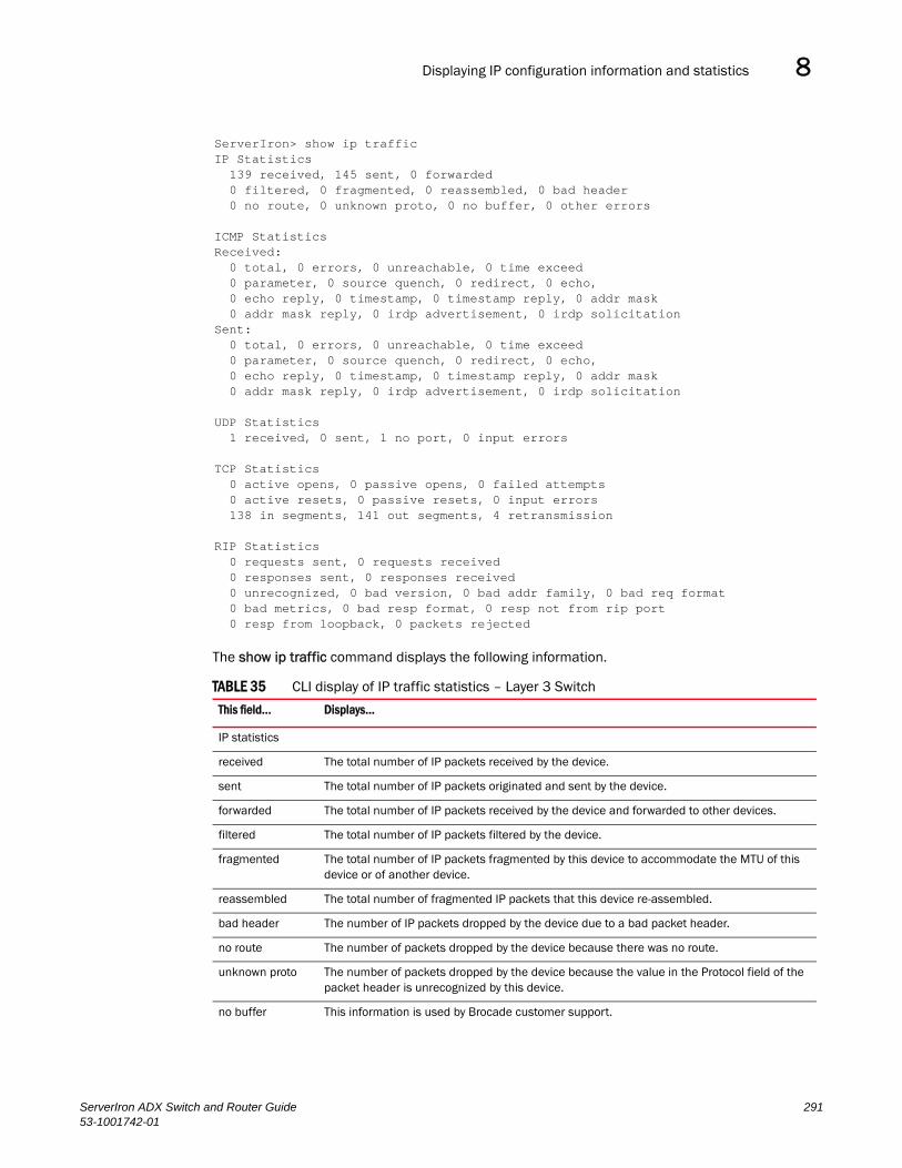
Displaying IP configuration information and statistics 8DRAFT: BROCADE CONFIDENTIAL
The show ip traffic command displays the following information.
TABLE 35 CLI display of IP traffic statistics – Layer 3 Switch
This field... Displays...
IP statistics
received The total number of IP packets received by the device.
sent The total number of IP packets originated and sent by the device.
forwarded The total number of IP packets received by the device and forwarded to other devices.
filtered The total number of IP packets filtered by the device.
fragmented The total number of IP packets fragmented by this device to accommodate the MTU of this device or of another device.
reassembled The total number of fragmented IP packets that this device re-assembled.
bad header The number of IP packets dropped by the device due to a bad packet header.
no route The number of packets dropped by the device because there was no route.
unknown proto The number of packets dropped by the device because the value in the Protocol field of the packet header is unrecognized by this device.
no buffer This information is used by Brocade customer support.
ServerIron> show ip trafficIP Statistics 139 received, 145 sent, 0 forwarded 0 filtered, 0 fragmented, 0 reassembled, 0 bad header 0 no route, 0 unknown proto, 0 no buffer, 0 other errors
ICMP StatisticsReceived: 0 total, 0 errors, 0 unreachable, 0 time exceed 0 parameter, 0 source quench, 0 redirect, 0 echo, 0 echo reply, 0 timestamp, 0 timestamp reply, 0 addr mask 0 addr mask reply, 0 irdp advertisement, 0 irdp solicitationSent: 0 total, 0 errors, 0 unreachable, 0 time exceed 0 parameter, 0 source quench, 0 redirect, 0 echo, 0 echo reply, 0 timestamp, 0 timestamp reply, 0 addr mask 0 addr mask reply, 0 irdp advertisement, 0 irdp solicitation
UDP Statistics 1 received, 0 sent, 1 no port, 0 input errors
TCP Statistics 0 active opens, 0 passive opens, 0 failed attempts 0 active resets, 0 passive resets, 0 input errors 138 in segments, 141 out segments, 4 retransmission
RIP Statistics 0 requests sent, 0 requests received 0 responses sent, 0 responses received 0 unrecognized, 0 bad version, 0 bad addr family, 0 bad req format 0 bad metrics, 0 bad resp format, 0 resp not from rip port 0 resp from loopback, 0 packets rejected
ServerIron ADX Switch and Router Guide 29153-1001742-01
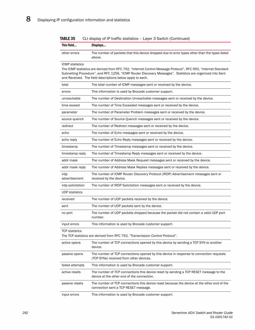
Displaying IP configuration information and statistics8DRAFT: BROCADE CONFIDENTIAL
other errors The number of packets that this device dropped due to error types other than the types listed above.
ICMP statisticsThe ICMP statistics are derived from RFC 792, “Internet Control Message Protocol”, RFC 950, “Internet Standard Subnetting Procedure”, and RFC 1256, “ICMP Router Discovery Messages”. Statistics are organized into Sent and Received. The field descriptions below apply to each.
total The total number of ICMP messages sent or received by the device.
errors This information is used by Brocade customer support.
unreachable The number of Destination Unreachable messages sent or received by the device.
time exceed The number of Time Exceeded messages sent or received by the device.
parameter The number of Parameter Problem messages sent or received by the device.
source quench The number of Source Quench messages sent or received by the device.
redirect The number of Redirect messages sent or received by the device.
echo The number of Echo messages sent or received by the device.
echo reply The number of Echo Reply messages sent or received by the device.
timestamp The number of Timestamp messages sent or received by the device.
timestamp reply The number of Timestamp Reply messages sent or received by the device.
addr mask The number of Address Mask Request messages sent or received by the device.
addr mask reply The number of Address Mask Replies messages sent or received by the device.
irdp advertisement
The number of ICMP Router Discovery Protocol (IRDP) Advertisement messages sent or received by the device.
irdp solicitation The number of IRDP Solicitation messages sent or received by the device.
UDP statistics
received The number of UDP packets received by the device.
sent The number of UDP packets sent by the device.
no port The number of UDP packets dropped because the packet did not contain a valid UDP port number.
input errors This information is used by Brocade customer support.
TCP statisticsThe TCP statistics are derived from RFC 793, “Transmission Control Protocol”.
active opens The number of TCP connections opened by this device by sending a TCP SYN to another device.
passive opens The number of TCP connections opened by this device in response to connection requests (TCP SYNs) received from other devices.
failed attempts This information is used by Brocade customer support.
active resets The number of TCP connections this device reset by sending a TCP RESET message to the device at the other end of the connection.
passive resets The number of TCP connections this device reset because the device at the other end of the connection sent a TCP RESET message.
input errors This information is used by Brocade customer support.
TABLE 35 CLI display of IP traffic statistics – Layer 3 Switch (Continued)
This field... Displays...
292 ServerIron ADX Switch and Router Guide53-1001742-01
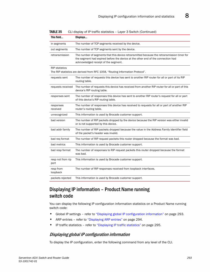
Displaying IP configuration information and statistics 8DRAFT: BROCADE CONFIDENTIAL
Displaying IP information – Product Name running switch codeYou can display the following IP configuration information statistics on a Product Name running switch code:
• Global IP settings – refer to “Displaying global IP configuration information” on page 293.
• ARP entries – refer to “Displaying ARP entries” on page 294.
• IP traffic statistics – refer to “Displaying IP traffic statistics” on page 295.
Displaying global IP configuration information
To display the IP configuration, enter the following command from any level of the CLI.
in segments The number of TCP segments received by the device.
out segments The number of TCP segments sent by the device.
retransmission The number of segments that this device retransmitted because the retransmission timer for the segment had expired before the device at the other end of the connection had acknowledged receipt of the segment.
RIP statisticsThe RIP statistics are derived from RFC 1058, “Routing Information Protocol”.
requests sent The number of requests this device has sent to another RIP router for all or part of its RIP routing table.
requests received The number of requests this device has received from another RIP router for all or part of this device’s RIP routing table.
responses sent The number of responses this device has sent to another RIP router’s request for all or part of this device’s RIP routing table.
responses received
The number of responses this device has received to requests for all or part of another RIP router’s routing table.
unrecognized This information is used by Brocade customer support.
bad version The number of RIP packets dropped by the device because the RIP version was either invalid or is not supported by this device.
bad addr family The number of RIP packets dropped because the value in the Address Family Identifier field of the packet’s header was invalid.
bad req format The number of RIP request packets this router dropped because the format was bad.
bad metrics This information is used by Brocade customer support.
bad resp format The number of responses to RIP request packets this router dropped because the format was bad.
resp not from rip port
This information is used by Brocade customer support.
resp from loopback
The number of RIP responses received from loopback interfaces.
packets rejected This information is used by Brocade customer support.
TABLE 35 CLI display of IP traffic statistics – Layer 3 Switch (Continued)
This field... Displays...
ServerIron ADX Switch and Router Guide 29353-1001742-01

Displaying IP configuration information and statistics8DRAFT: BROCADE CONFIDENTIAL
Syntax: show ip
This display shows the following information.
Displaying ARP entries
To display the ARP cache, enter the following command from any level of the CLI.
Syntax: show arp
This display shows the following information.
TABLE 36 CLI display of global IP configuration information – Layer 2 Switch
This field... Displays...
IP configuration
Switch IP address The management IP address you configured on the Product Name. Specify this address for Telnet or Web management access.
Subnet mask The subnet mask for the management IP address.
Default router address The address of the default gateway, if you specified one.
Most recent TFTP access
TFTP server address The IP address of the most-recently contacted TFTP server, if the Layer 2 Switch has contacted a TFTP server since the last time the software was reloaded or the Layer 2 Switch was rebooted.
Configuration filename The name under which the Layer 2 Switch’s startup-config file was uploaded or downloaded during the most recent TFTP access.
Image filename The name of the Layer 2 Switch flash image (system software file) that was uploaded or downloaded during the most recent TFTP access.
TABLE 37 CLI display of ARP cache
This field... Displays...
IP The IP address of the device.
Mac The MAC address of the device.
NOTE: If the MAC address is all zeros, the entry is for the default gateway, but the Layer 2 Switch does not have a link to the gateway.
ServerIron(config)# show ip
Switch IP address: 192.168.1.2
Subnet mask: 255.255.255.0
Default router address: 192.168.1.1 TFTP server address: NoneConfiguration filename: None Image filename: None
ServerIron(config)# show arp
IP Mac Port Age VlanId192.168.1.170 0010.5a11.d042 7 0 1Total Arp Entries : 1
294 ServerIron ADX Switch and Router Guide53-1001742-01

Displaying IP configuration information and statistics 8DRAFT: BROCADE CONFIDENTIAL
Displaying IP traffic statistics
To display IP traffic statistics, enter the following command at any CLI level.
Syntax: show ip traffic
The show ip traffic command displays the following information.
Port The port on which the entry was learned.
Age The number of minutes the entry has remained unused. If this value reaches the ARP aging period, the entry is removed from the cache.
VlanId The VLAN the port that learned the entry is in.
NOTE: If the MAC address is all zeros, this field shows a random VLAN ID, since the Layer 2 Switch does not yet know which port the device for this entry is attached to.
Total ARP Entries The number of entries in the ARP cache.
TABLE 38 CLI display of IP traffic statistics – Layer 2 Switch
This field... Displays...
IP statistics
received The total number of IP packets received by the device.
sent The total number of IP packets originated and sent by the device.
TABLE 37 CLI display of ARP cache (Continued)
This field... Displays...
ServerIron# show ip traffic
IP Statistics 27 received, 24 sent 0 fragmented, 0 reassembled, 0 bad header 0 no route, 0 unknown proto, 0 no buffer, 0 other errors
ICMP StatisticsReceived: 0 total, 0 errors, 0 unreachable, 0 time exceed 0 parameter, 0 source quench, 0 redirect, 0 echo, 0 echo reply, 0 timestamp, 0 timestamp rely, 0 addr mask 0 addr mask reply, 0 irdp advertisement, 0 irdp solicitationSent: 0 total, 0 errors, 0 unreachable, 0 time exceed 0 parameter, 0 source quench, 0 redirect, 0 echo, 0 echo reply, 0 timestamp, 0 timestamp rely, 0 addr mask 0 addr mask reply, 0 irdp advertisement, 0 irdp solicitation
UDP Statistics 0 received, 0 sent, 0 no port, 0 input errors
TCP Statistics 1 current active tcbs, 4 tcbs allocated, 0 tcbs freed 0 tcbs protected 0 active opens, 0 passive opens, 0 failed attempts 0 active resets, 0 passive resets, 0 input errors 27 in segments, 24 out segments, 0 retransmission
ServerIron ADX Switch and Router Guide 29553-1001742-01

Displaying IP configuration information and statistics8DRAFT: BROCADE CONFIDENTIAL
fragmented The total number of IP packets fragmented by this device to accommodate the MTU of this device or of another device.
reassembled The total number of fragmented IP packets that this device re-assembled.
bad header The number of IP packets dropped by the device due to a bad packet header.
no route The number of packets dropped by the device because there was no route.
unknown proto The number of packets dropped by the device because the value in the Protocol field of the packet header is unrecognized by this device.
no buffer This information is used by Brocade customer support.
other errors The number of packets that this device dropped due to error types other than the types listed above.
ICMP statisticsThe ICMP statistics are derived from RFC 792, “Internet Control Message Protocol”, RFC 950, “Internet Standard Subnetting Procedure”, and RFC 1256, “ICMP Router Discovery Messages”. Statistics are organized into Sent and Received. The field descriptions below apply to each.
total The total number of ICMP messages sent or received by the device.
errors This information is used by Brocade customer support.
unreachable The number of Destination Unreachable messages sent or received by the device.
time exceed The number of Time Exceeded messages sent or received by the device.
parameter The number of Parameter Problem messages sent or received by the device.
source quench The number of Source Quench messages sent or received by the device.
redirect The number of Redirect messages sent or received by the device.
echo The number of Echo messages sent or received by the device.
echo reply The number of Echo Reply messages sent or received by the device.
timestamp The number of Timestamp messages sent or received by the device.
timestamp reply The number of Timestamp Reply messages sent or received by the device.
addr mask The number of Address Mask Request messages sent or received by the device.
addr mask reply The number of Address Mask Replies messages sent or received by the device.
irdp advertisement The number of ICMP Router Discovery Protocol (IRDP) Advertisement messages sent or received by the device.
irdp solicitation The number of IRDP Solicitation messages sent or received by the device.
UDP statistics
received The number of UDP packets received by the device.
sent The number of UDP packets sent by the device.
no port The number of UDP packets dropped because the packet did not contain a valid UDP port number.
input errors This information is used by Brocade customer support.
TCP statisticsThe TCP statistics are derived from RFC 793, “Transmission Control Protocol”.
TABLE 38 CLI display of IP traffic statistics – Layer 2 Switch (Continued)
This field... Displays...
296 ServerIron ADX Switch and Router Guide53-1001742-01

Displaying IP configuration information and statistics 8DRAFT: BROCADE CONFIDENTIAL
current active tcbs The number of TCP Control Blocks (TCBs) that are currently active.
tcbs allocated The number of TCBs that have been allocated.
tcbs freed The number of TCBs that have been freed.
tcbs protected This information is used by Brocade customer support.
active opens The number of TCP connections opened by this device by sending a TCP SYN to another device.
passive opens The number of TCP connections opened by this device in response to connection requests (TCP SYNs) received from other devices.
failed attempts This information is used by Brocade customer support.
active resets The number of TCP connections this device reset by sending a TCP RESET message to the device at the other end of the connection.
passive resets The number of TCP connections this device reset because the device at the other end of the connection sent a TCP RESET message.
input errors This information is used by Brocade customer support.
in segments The number of TCP segments received by the device.
out segments The number of TCP segments sent by the device.
retransmission The number of segments that this device retransmitted because the retransmission timer for the segment had expired before the device at the other end of the connection had acknowledged receipt of the segment.
TABLE 38 CLI display of IP traffic statistics – Layer 2 Switch (Continued)
This field... Displays...
ServerIron ADX Switch and Router Guide 29753-1001742-01

Displaying IP configuration information and statistics8DRAFT: BROCADE CONFIDENTIAL
298 ServerIron ADX Switch and Router Guide53-1001742-01
ServerIron ADX Switch and Router Guide53-1001742-01
DRAFT: BROCADE CONFIDENTIAL
Chapter
9
Configuring RIPIn this chapter•Overview. . . . . . . . . . . . . . . . . . . . . . . . . . . . . . . . . . . . . . . . . . . . . . . . . . . . . 299
•RIP parameters and defaults . . . . . . . . . . . . . . . . . . . . . . . . . . . . . . . . . . . . 300
•Configuring RIP parameters . . . . . . . . . . . . . . . . . . . . . . . . . . . . . . . . . . . . . 301
•Displaying RIP filters . . . . . . . . . . . . . . . . . . . . . . . . . . . . . . . . . . . . . . . . . . . 309
•Displaying CPU utilization statistics . . . . . . . . . . . . . . . . . . . . . . . . . . . . . . . 310
OverviewRouting Information Protocol (RIP) is an IP route exchange protocol that uses a distance vector (a number representing distance) to measure the cost of a given route. The cost is a distance vector because the cost often is equivalent to the number of router hops between the Product Name and the destination network.
A Product Name can receive multiple paths to a destination. The software evaluates the paths, selects the best path, and saves the path in the IP route table as the route to the destination. Typically, the best path is the path with the fewest hops. A hop is another router through which packets must travel to reach the destination. If the Product Name receives a RIP update from another router that contains a path with fewer hops than the path stored in the route table of the Product Name, it replaces the older route with the newer one. The Product Name then includes the new path in the updates it sends to other RIP routers, including Product Name switches.
RIP routers, including the Product Name, also can modify a route’s cost, generally by adding to it, to bias the selection of a route for a given destination. In this case, the actual number of router hops may be the same, but the route has an administratively higher cost and is thus less likely to be used than other, lower-cost routes.
A RIP route can have a maximum cost of 15. Any destination with a higher cost is considered unreachable. Although limiting to larger networks, the low maximum hop count prevents endless loops in the network.
The Product Name supports the following RIP versions:
• Version 1
• V1 compatible with V2
• Version 2 (the default)
ICMP Host Unreachable message for undeliverable ARPsIf the router receives an ARP request packet that it is unable to deliver to the final destination because of the ARP timeout and no ARP response is received (router knows of no route to the destination address), the router sends an ICMP Host Unreachable message to the source.
299

RIP parameters and defaults9DRAFT: BROCADE CONFIDENTIAL
RIP parameters and defaultsThe following tables list the RIP parameters, their default values, and where to find configuration information.
RIP global parametersTable 39 lists the global RIP parameters and their default values, and indicates where you can find configuration information.
TABLE 39 RIP global parameters
Parameter Description Default See page...
RIP state The global state of the protocol
NOTE: You also must enable the protocol on individual interfaces. Globally enabling the protocol does not allow interfaces to send and receive RIP information. Refer to Table 40 on page 301.
Disabled page 301
Administrative distance
The administrative distance is a numeric value assigned to each type of route on the router. When the router is selecting from among multiple routes (sometimes of different origins) to the same destination, the router compares the administrative distances of the routes and selects the route with the lowest administrative distance.This parameter applies to routes originated by RIP. The administrative distance stays with a route when it is redistributed into other routing protocols.
120 page 303
Redistribution RIP can redistribute routes from other routing protocols such as OSPF into RIP. A redistributed route is one that a router learns through another protocol, then distributes into RIP.
Disabled page 303
Redistribution metric
RIP assigns a RIP metric (cost) to each external route redistributed from another routing protocol into RIP. An external route is a route with at least one hop (packets must travel through at least one other router to reach the destination).This parameter applies to routes that are redistributed from other protocols into RIP.
1 (one) page 305
Update interval How often the router sends route updates to its RIP neighbors
30 seconds
page 306
Learning default routes
The router can learn default routes from its RIP neighbors.
NOTE: You also can enable or disable this parameter on an individual interface basis. Refer to Table 40 on page 301.
Disabled page 306
Advertising and learning with specific neighbors
The Layer 3 Switch learns and advertises RIP routes with all its neighbors by default. You can prevent the Layer 3 Switch from advertising routes to specific neighbors or learning routes from specific neighbors.
Learning and advertising permitted for all neighbors
page 306
300 ServerIron ADX Switch and Router Guide53-1001742-01

Configuring RIP parameters 9DRAFT: BROCADE CONFIDENTIAL
RIP interface parametersTable 40 lists the interface-level RIP parameters and their default values, and indicates where you can find configuration information..
Configuring RIP parametersUse the following procedures to configure RIP parameters on a system-wide and individual interface basis.
Enabling RIPRIP is disabled by default. To enable RIP globally, enter the following command.
NOTEYou must enable the protocol globally and also on individual interfaces on which you want to advertise RIP. Globally enabling the protocol does not enable it on individual interfaces.
ServerIron(config)# router rip
Syntax: [no] router rip
TABLE 40 RIP interface parameters
Parameter Description Default See page...
RIP state and version
The state of the protocol and the version that is supported on the interface. The version can be one of the following:• Version 1 only• Version 2 only• Version 1, but also compatible with version 2
NOTE: You also must enable RIP globally.
Disabled page 301
Metric A numeric cost the router adds to RIP routes learned on the interface. This parameter applies only to RIP routes.
1 (one) page 302
Learning default routes
Locally overrides the global setting. Refer to Table 39 on page 300.
Disabled page 306
Loop prevention The method a router uses to prevent routing loops caused by advertising a route on the same interface as the one on which the router learned the route:• Split horizon – The router does not advertise a
route on the same interface as the one on which the router learned the route.
• Poison reverse – The router assigns a cost of 16 (“infinite” or “unreachable”) to a route before advertising it on the same interface as the one on which the router learned the route.
Poison reverse
NOTE: Enabling split horizon disables poison reverse on the interface.
page 307
Advertising and learning specific routes
You can control the routes that a Layer 3 Switch learns or advertises.
The Layer 3 Switch learns and advertises all RIP routes on all interfaces.
page 308
ServerIron ADX Switch and Router Guide 30153-1001742-01

Configuring RIP parameters9DRAFT: BROCADE CONFIDENTIAL
After globally enabling the protocol, you must enable it on individual interfaces. You can enable the protocol on physical interfaces as well as virtual routing interfaces. To enable RIP on an interface, enter commands such as the following.
ServerIron(config)# interface ethernet 1/1ServerIron(config-if-1/1)# ip rip v1-only
Syntax: [no] ip rip v1-only | v1-compatible-v2 | v2-only
NOTEYou must specify the RIP version.
Configuring metric parametersBy default, a Product Name port increases the cost of a RIP route that is learned on the port by one. You can configure individual ports to add more than one to a learned route’s cost. In addition, you can configure a RIP offset list to increase the metric for learned or advertised routes based on network address.
Changing the cost of routes learned on a port
By default, a port increases the cost of a RIP route that is learned on the port. The Product Name increases the cost by adding one to the route’s metric before storing the route.
You can change the amount that an individual port adds to the metric of RIP routes learned on the port.
NOTERIP considers a route with a metric of 16 to be unreachable. Use this metric only if you do not want the route to be used. In fact, you can prevent the Layer 3 Switch from using a specific port for routes learned though that port by setting its metric to 16.
To increase the cost a port adds to RIP routes learned in that port, enter commands such as the following.
ServerIron(config)# interface ethernet 6/1ServerIron(config-if-6/1)# ip metric 5
These commands configure port 6/1 to add 5 to the cost of each route learned on the port.
Syntax: ip metric <1-16>
Configuring a RIP offset list
A RIP offset list allows you to add to the metric of specific inbound or outbound routes learned or advertised by RIP. RIP offset lists provide a simple method for adding to the cost of specific routes and therefore biasing the switch route selection of the Product Name away from those routes.
An offset list consists of the following parameters:
• An ACL that specifies the routes to which to add the metric.
• The direction:
• In applies to routes the Product Name learns from RIP neighbors.
• Out applies to routes the Product Name is advertising to its RIP neighbors.
302 ServerIron ADX Switch and Router Guide53-1001742-01
Configuring RIP parameters 9DRAFT: BROCADE CONFIDENTIAL
• The type and number of a specific port to which the offset list applies (optional).
The software adds the offset value to the routing metric (cost) of the routes that match the ACL. If a route matches both a global offset list and an interface-based offset list, the interface-based offset list takes precedence. The interface-based offset list’s metric is added to the route in this case.
You can configure up to 24 global RIP offset lists and up to 24 RIP offset lists on each interface.
To configure a global RIP offset list, enter commands such as the following.
ServerIron(config)# access-list 21 deny 160.1.0.0 0.0.255.255ServerIron(config)# access-list 21 permit anyServerIron(config)# router ripServerIron(config-rip-router)# offset-list 21 out 10
The commands in this example configure a standard ACL. The ACL matches on all IP networks except 160.1.x.x. When the Product Name advertises a route that matches ACL 21, the offset list adds 10 to the route’s metric.
Syntax: [no] <acl-number-or-name> in | out offset [ethernet | pos <portnum>]
In the following example, the Product Name uses ACL 21 to add 10 to the metric of routes received on Ethernet port 2/1.
ServerIron(config-rip-router)# offset-list 21 in ethernet 2/1
Changing the administrative distanceBy default, the Product Name assigns the default RIP administrative distance (120) to RIP routes. When comparing routes based on administrative distance, the Product Name selects the route with the lower distance. You can change the administrative distance for RIP routes.
To change the administrative distance for RIP routes, enter a command such as the following.
ServerIron(config-rip-router)# distance 140
This command changes the administrative distance to 140 for all RIP routes.
Syntax: [no] distance <num>
Configuring redistributionYou can configure the Product Name to redistribute routes learned through Open Shortest Path First into RIP. When you redistribute a route from one of these other protocols into RIP, the Product Name can use RIP to advertise the route to its RIP neighbors.
To configure redistribution, perform the following tasks:
• Configure redistribution filters (optional). You can configure filters to permit or deny redistribution for a route based on its origin (OSPF, and so on), the destination network address, and the route’s metric. You also can configure a filter to set the metric based on these criteria.
• Change the default redistribution metric (optional). The Product Name assigns a RIP metric of one to each redistributed route by default. You can change the default metric to a value up to 16.
• Enable redistribution.
ServerIron ADX Switch and Router Guide 30353-1001742-01
Configuring RIP parameters9DRAFT: BROCADE CONFIDENTIAL
NOTEDo not enable redistribution until you configure the other redistribution parameters.
Configuring redistribution filters
RIP redistribution filters apply to all interfaces. The software uses the filters in ascending numerical order and immediately takes the action specified by the filter. Thus, if filter 1 denies redistribution of a given route, the software does not redistribute the route, regardless of whether a filter with a higher ID permits redistribution of that route.
NOTEThe default redistribution action is permit, even after you configure and apply redistribution filters to the virtual routing interface. If you want to tightly control redistribution, apply a filter to deny all routes as the last filter (the filter with the highest ID), then apply filters with lower filter IDs to allow specific routes.
To configure a redistribution filter, enter a command such as the following.
ServerIron(config-rip-router)# deny redistribute 2 all address 207.92.0.0 255.255.0.0
This command denies redistribution for all types of routes to the 207.92.x.x network.
Syntax: [no] permit | deny redistribute <filter-num> all | ospf | static address <ip-addr> <ip-mask> [match-metric <value> | set-metric <value>]
The <filter-num> specifies the redistribution filter ID. The software uses the filters in ascending numerical order. Thus, if filter 1 denies a route from being redistributed, the software does not redistribute that route even if a filter with a higher ID permits redistribution of the route.
The all parameter applies redistribution to all route types.
The ospf parameter applies redistribution to OSPF routes only.
The static parameter applies redistribution to IP static routes only.
The address <ip-addr> <ip-mask> parameters apply redistribution to the specified network and subnet address. Use 0 to specify “any”. For example, “207.92.0.0 255.255.0.0“ means “any 207.92.x.x subnet”. However, to specify any subnet (all subnets match the filter), enter “address 255.255.255.255 255.255.255.255”.
The match-metric <value> parameter applies the redistribution filter only to those routes with the specified metric value; possible values are from 1 – 15.
The set-metric <value> parameter sets the RIP metric value that will be applied to those routes imported into RIP.
The following command denies redistribution into RIP for all OSPF routes.
ServerIron(config-rip-router)# deny redistribute 3 ospf address 207.92.0.0 255.255.0.0
The following command denies redistribution for all OSPF routes that have a metric of 10.
ServerIron(config-rip-router)# deny redistribute 3 ospf address 207.92.0.0 255.255.0.0 match-metric 10
304 ServerIron ADX Switch and Router Guide53-1001742-01

Configuring RIP parameters 9DRAFT: BROCADE CONFIDENTIAL
The following commands deny redistribution of all routes except routes for 10.10.10.x and 20.20.20.x.
ServerIron(config-rip-router)# deny redistribute 64 static address 255.255.255.255 255.255.255.255ServerIron(config-rip-router)# permit redistribute 1 static address 10.10.10.0 255.255.255.0ServerIron(config-rip-router)# permit redistribute 2 static address 20.20.20.0 255.255.255.0
NOTEThis example assumes that the highest RIP redistribution filter ID configured on the device is 64.
Changing the redistribution metric
When the Product Name redistributes a route into RIP, the software assigns a RIP metric (cost) to the route. By default, the software assigns a metric of one to each route that is redistributed into RIP. You can increase the metric that the Product Name assigns, up to 15.
To change the RIP metric the Layer 3 Switch assigns to redistributed routes, enter a command such as the following.
ServerIron(config-rip-router)# default-metric 10
This command assigns a RIP metric of 10 to each route that is redistributed into RIP.
Syntax: [no] default-metric <1-15>
Enabling redistribution
After you configure redistribution parameters, you need to enable redistribution.
To enable RIP redistribution, enter the following command.
ServerIron(config-rip-router)# redistribution
Syntax: [no] redistribution
Configuring route learning and advertising parametersBy default, a Product Name learns routes from all its RIP neighbors and advertises RIP routes to those neighbors.
You can configure the following learning and advertising parameters:
• Update interval – The update interval specifies how often the Product Name sends RIP route advertisements to its neighbors. The default is 30 seconds. You can change the interval to a value from 1 – 1000 seconds.
• Learning and advertising of RIP default routes – The Product Name learns and advertises RIP default routes by default. You can disable learning and advertising of default routes on a global or individual interface basis.
• Learning of standard RIP routes – By default, the Product Name can learn RIP routes from all its RIP neighbors. You can configure RIP neighbor filters to explicitly permit or deny learning from specific neighbors.
ServerIron ADX Switch and Router Guide 30553-1001742-01

Configuring RIP parameters9DRAFT: BROCADE CONFIDENTIAL
Changing the update interval for route advertisements
The update interval specifies how often the Product Name sends route advertisements to its RIP neighbors. You can specify an interval from 1 – 1000 seconds. The default is 30 seconds.
To change the RIP update interval, enter a command such as the following.
ServerIron(config-rip-router)# update 120
This command configures the Layer 3 Switch to send RIP updates every 120 seconds.
Syntax: update-time <1-1000>
Enabling learning of RIP default routes
By default, the Product Name does not learn RIP default routes. You can enable learning of RIP default routes on a global or interface basis.
To enable learning of default RIP routes on a global basis, enter the following command.
ServerIron(config-rip-router)# learn-default
Syntax: [no] learn-default
To enable learning of default RIP routes on an interface basis, enter commands such as the following.
ServerIron(config)# interface ethernet 1/1ServerIron(config-if-1/1)# ip rip learn-defaul
Syntax: [no] ip rip learn-default
Configuring a RIP neighbor filter
By default, a Product Name learns RIP routes from all its RIP neighbors. Neighbor filters allow you to specify the neighbor routers from which the device can receive RIP routes. Neighbor filters apply globally to all ports.
To configure a RIP neighbor filters, enter a command such as the following.
ServerIron(config-rip-router)# neighbor 1 deny any
Syntax: [no] neighbor <filter-num> permit | deny <source-ip-address> | any
This command configures the Product Name so that the device does not learn any RIP routes from any RIP neighbors.
The following commands configure the Product Name to learn routes from all neighbors except 192.168.1.170. Once you define a RIP neighbor filter, the default action changes from learning all routes from all neighbors to denying all routes from all neighbors except the ones you explicitly permit. Thus, to deny learning from a specific neighbor but allow all other neighbors, you must add a filter that allows learning from all neighbors. Make sure you add the filter to permit all neighbors as the last filter (the one with the highest filter number). Otherwise, the software can match on the permit all filter before a filter that denies a specific neighbor, and learn routes from that neighbor.
ServerIron(config-rip-router)# neighbor 2 deny 192.16.1.170ServerIron(config-rip-router)# neighbor 1024 permit any
306 ServerIron ADX Switch and Router Guide53-1001742-01

Configuring RIP parameters 9DRAFT: BROCADE CONFIDENTIAL
Changing the route loop prevention methodRIP can use the following methods to prevent routing loops:
• Split horizon – The Product Name does not advertise a route on the same interface as the one on which the router learned the route.
• Poison reverse – The Product Name assigns a cost of 16 (“infinite” or “unreachable”) to a route before advertising it on the same interface as the one on which the router learned the route. This is the default.
These loop prevention methods are configurable on an individual interface basis. One of the methods is always in effect on an interface enabled for RIP. Thus, if you disable one method, the other method is enabled.
NOTEThese methods are in addition to RIP’s maximum valid route cost of 15.
To disable poison reverse and enable split horizon on an interface, enter commands such as the following.
ServerIron(config)# interface ethernet 1/1ServerIron(config-if-1/1)# no ip rip poison-reverse
Syntax: [no] ip rip poison-reverse
To disable split horizon and enable poison reverse on an interface, enter commands such as the following.
ServerIron(config)# interface ethernet 1/1ServerIron(config-if-1/1)# ip rip poison-reverse
Suppressing RIP route advertisement on a VRRP or VRRPE Backup interface
NOTEThis section applies only if you configure the Product Name for Virtual Router Redundancy Protocol (VRRP) or VRRP Extended (VRRPE).
Normally, a VRRP or VRRPE Backup includes route information for the virtual IP address (the backed up interface) in RIP advertisements. As a result, other routers receive multiple paths for the backed up interface and might sometimes unsuccessfully use the path to the Backup rather than the path to the Master.
You can prevent the Backups from advertising route information for the backed up interface by enabling suppression of the advertisements.
To suppress RIP advertisements for the backed up interface in Router2, enter the following commands.
ServerIron(config)# router ripServerIron(config-rip-router)# use-vrrp-path
Syntax: [no] use-vrrp-path
The syntax is the same for VRRP and VRRPE.
ServerIron ADX Switch and Router Guide 30753-1001742-01
Configuring RIP parameters9DRAFT: BROCADE CONFIDENTIAL
Configuring RIP route filtersYou can configure RIP route filters to permit or deny learning or advertising of specific routes. Configure the filters globally, then apply them to individual interfaces. When you apply a RIP route filter to an interface, you specify whether the filter applies to learned routes (in) or advertised routes (out).
NOTEA route is defined by the destination’s IP address and network mask.
NOTEBy default, routes that do not match a route filter are learned or advertised. To prevent a route from being learned or advertised, you must configure a filter to deny the route.
To configure RIP filters, enter commands such as the following.
ServerIron(config-rip-router)# filter 1 permit 192.53.4.1 255.255.255.0ServerIron(config-rip-router)# filter 2 permit 192.53.5.1 255.255.255.0ServerIron(config-rip-router)# filter 3 permit 192.53.6.1 255.255.255.0ServerIron(config-rip-router)# filter 4 deny 192.53.7.1 255.255.255.0
These commands explicitly permit RIP routes to three networks, and deny the route to one network.
Since the default action is permit, all other routes (routes not explicitly permitted or denied by the filters) can be learned or advertised.
Syntax: filter <filter-num> permit | deny <source-ip-address> | any <source-mask> | any [log]
Applying a RIP route filter to an interface
Once you define RIP route filters, you must assign them to individual interfaces. The filters do not take effect until you apply them to interfaces. When you apply a RIP route filter, you also specify whether the filter applies to learned routes or advertised routes:
• Out filters apply to routes the Product Name advertises to its neighbor on the interface.
• In filters apply to routes the Product Name learns from its neighbor on the interface.
To apply RIP route filters to an interface, enter commands such as the following.
ServerIron(config)# interface ethernet 1/2ServerIron(config-if-1/2)# ip rip filter-group in 2 3 4
Syntax: [no] ip rip filter-group in | out <filter-list>
These commands apply RIP route filters 2, 3, and 4 to all routes learned from the RIP neighbor on port 1/2.
Setting RIP timersYou can set three new timers for the RIP protocol. The new timers-basic command allows you to set the RIP update timer, aging timeout interval, and garbage-collection timer. The RIP protocol must be enabled on the device in order to set these timers.
The RIP update-time command, available in previous releases, has lower priority than the timers-basic command. If both commands are configured on the device, then the update-time command is ignored.
308 ServerIron ADX Switch and Router Guide53-1001742-01

Displaying RIP filters 9DRAFT: BROCADE CONFIDENTIAL
For example, the following command sets the three RIP timers.
ServerIron(config) router ripServerIron(config-rip-router)# timers-basic 5 15 15
Syntax: [no] timers-basic <update-timer> <aging-timeout-interval> <garbage-collection-timer>
The <update-timer> specifies how often RIP update messages are sent. You can specify from 1 – 1,000 seconds. The default is 30 seconds.
The <aging-timeout-interval> specifies how long the Product Namee waits for a route update before declaring a route invalid. The value specified for the <aging-timeout-interval> should be at least three times the value specified for the <update-timer>. The <aging-timeout-interval> can be from 3 – 3,000 seconds. The default is 180 seconds.
The <garbage-collection-timer> specifies how long the Product Name waits for a route update before removing the route from the RIP route table. The value specified for the <garbage-collection-timer> should be at least three times the value specified for the <update-timer>. The <garbage-collection-timer> can be from 3 – 3,000 seconds. The default is 120 seconds.
Displaying RIP filtersTo display RIP filters, enter the following command at any CLI level.
Syntax: show ip rip
This display shows the following information.
TABLE 41 CLI display of RIP filter information
This field... Displays...
Route filtersThe rows underneath “RIP Route Filter Table” list the RIP route filters. If no RIP route filters are configured on the device, the following message is displayed instead: “No Filters are configured in RIP Route Filter Table”.
Index The filter number. You assign this number when you configure the filter.
ServerIron> show ip rip
RIP Route Filter Table Index Action Route IP Address Subnet Mask 1 deny any any RIP Neighbor Filter Table Index Action Neighbor IP Address 1 permit any
ServerIron ADX Switch and Router Guide 30953-1001742-01

Displaying CPU utilization statistics9DRAFT: BROCADE CONFIDENTIAL
Displaying CPU utilization statisticsTo display CPU utilization statistics for RIP for the previous one-second, one-minute, five-minute, and fifteen-minute intervals, enter the following command at any level of the CLI.
Action The action the router takes if a RIP route packet matches the IP address and subnet mask of the filter. The action can be one of the following:• deny – RIP route packets that match the address and network mask
information in the filter are dropped. If applied to an interface’s outbound filter group, the filter prevents the router from advertising the route on that interface. If applied to an interface’s inbound filter group, the filter prevents the router from adding the route to its IP route table.
• permit – RIP route packets that match the address and network mask information are accepted. If applied to an interface’s outbound filter group, the filter allows the router to advertise the route on that interface. If applied to an interface’s inbound filter group, the filter allows the router to add the route to its IP route table.
Route IP Address The IP address of the route’s destination network or host.
Subnet Mask The network mask for the IP address.
Neighbor filtersThe rows underneath “RIP Neighbor Filter Table” list the RIP neighbor filters. If no RIP neighbor filters are configured on the device, the following message is displayed instead: “No Filters are configured in RIP Neighbor Filter Table”.
Index The filter number. You assign this number when you configure the filter.
Action The action the router takes for RIP route packets to or from the specified neighbor:• deny – If the filter is applied to an interface’s outbound filter group, the
filter prevents the router from advertising RIP routes to the specified neighbor on that interface. If the filter is applied to an interface’s inbound filter group, the filter prevents the router from receiving RIP updates from the specified neighbor.
• permit – If the filter is applied to an interface’s outbound filter group, the filter allows the router to advertise RIP routes to the specified neighbor on that interface. If the filter is applied to an interface’s inbound filter group, the filter allows the router to receive RIP updates from the specified neighbor.
Neighbor IP Address The IP address of the RIP neighbor.
TABLE 41 CLI display of RIP filter information (Continued)
This field... Displays...
ServerIron# show process cpuProcess Name 5Sec(%) 1Min(%) 5Min(%) 15Min(%) Runtime(ms)ARP 0.01 0.03 0.09 0.22 9BGP 0.04 0.06 0.08 0.14 13GVRP 0.00 0.00 0.00 0.00 0ICMP 0.00 0.00 0.00 0.00 0IP 0.00 0.00 0.00 0.00 0OSPF 0.00 0.00 0.00 0.00 0RIP 0.04 0.07 0.08 0.09 7STP 0.00 0.00 0.00 0.00 0VRRP 0.00 0.00 0.00 0.00 0
310 ServerIron ADX Switch and Router Guide53-1001742-01
Displaying CPU utilization statistics 9DRAFT: BROCADE CONFIDENTIAL
If the software has been running less than 15 minutes (the maximum interval for utilization statistics), the command indicates how long the software has been running. Here is an example.
To display utilization statistics for a specific number of seconds, enter a command such as the following.
When you specify how many seconds’ worth of statistics you want to display, the software selects the sample that most closely matches the number of seconds you specified. In this example, statistics are requested for the previous two seconds. The closest sample available is actually for the previous 1 second plus 80 milliseconds.
Syntax: show process cpu [<num>]
The <num> parameter specifies the number of seconds and can be from 1 – 900. If you use this parameter, the command lists the usage statistics only for the specified number of seconds. If you do not use this parameter, the command lists the usage statistics for the previous one-second, one-minute, five-minute, and fifteen-minute intervals.
ServerIron# show process cpuThe system has only been up for 6 seconds.Process Name 5Sec(%) 1Min(%) 5Min(%) 15Min(%) Runtime(ms)ARP 0.01 0.00 0.00 0.00 0BGP 0.00 0.00 0.00 0.00 0GVRP 0.00 0.00 0.00 0.00 0ICMP 0.01 0.00 0.00 0.00 1IP 0.00 0.00 0.00 0.00 0OSPF 0.00 0.00 0.00 0.00 0RIP 0.00 0.00 0.00 0.00 0STP 0.00 0.00 0.00 0.00 0VRRP 0.00 0.00 0.00 0.00 0
ServerIron# show process cpu 2Statistics for last 1 sec and 80 msProcess Name Sec(%) Time(ms)ARP 0.00 0BGP 0.00 0GVRP 0.00 0ICMP 0.01 1IP 0.00 0OSPF 0.00 0RIP 0.00 0STP 0.01 0VRRP 0.00 0
ServerIron ADX Switch and Router Guide 31153-1001742-01

Displaying CPU utilization statistics9DRAFT: BROCADE CONFIDENTIAL
312 ServerIron ADX Switch and Router Guide53-1001742-01
ServerIron ADX Switch and Router Guide53-1001742-01
DRAFT: BROCADE CONFIDENTIAL
Chapter
10
Configuring OSPFIn this chapter•Overview of OSPF. . . . . . . . . . . . . . . . . . . . . . . . . . . . . . . . . . . . . . . . . . . . . . 313
•Configuring OSPF. . . . . . . . . . . . . . . . . . . . . . . . . . . . . . . . . . . . . . . . . . . . . . 321
•Displaying OSPF information . . . . . . . . . . . . . . . . . . . . . . . . . . . . . . . . . . . . 351
This chapter describes how to configure OSPF on Brocade Layer 3 Switches using the CLI and Web Management Interface.
To display OSPF configuration information and statistics, refer to “Displaying OSPF information” on page 351.
NOTEThe ServerIron ADX, can contain 10000 routes by default.
Overview of OSPFOSPF is a link-state routing protocol. The protocol uses link-state advertisements (LSA) to update neighboring routers regarding its interfaces and information on those interfaces. The router floods these LSAs to all neighboring routers to update them regarding the interfaces. Each router maintains an identical database that describes its area topology to help a router determine the shortest path between it and any neighboring router.
The ServerIron ADX supports the following types of LSAs, which are described in RFC 1583:
• Router link
• Network link
• Summary link
• Autonomous system (AS) summary link
• AS external link
• Not-So-Stubby Area (NSSA) external link
OSPF is built upon a hierarchy of network components. The highest level of the hierarchy is the Autonomous System (AS). An autonomous system is defined as a number of networks, all of which share the same routing and administration characteristics.
An AS can be divided into multiple areas as shown in Figure 67 on page 314. Each area represents a collection of contiguous networks and hosts. Areas limit the area to which link-state advertisements are broadcast, thereby limiting the amount of flooding that occurs within the network. An area is represented in OSPF by either an IP address or a number.
313

Overview of OSPF10DRAFT: BROCADE CONFIDENTIAL
You can further limit the broadcast area of flooding by defining an area range. The area range allows you to assign an aggregate value to a range of IP addresses. This aggregate value becomes the address that is advertised instead all of the individual addresses it represents being advertised. You can assign up to 32 ranges in an OSPF area.
An OSPF router can be a member of multiple areas. Routers with membership in multiple areas are known as Area Border Routers (ABRs). Each ABR maintains a separate topological database for each area the router is in. Each topological database contains all of the LSA databases for each router within a given area. The routers within the same area have identical topological databases. The ABR is responsible for forwarding routing information or changes between its border areas.
An Autonomous System Boundary Router (ASBR) is a router that is running multiple protocols and serves as a gateway to routers outside an area and those operating with different protocols. The ASBR is able to import and translate different protocol routes into OSPF through a process known as redistribution. For more details on redistribution and configuration examples, refer to “Enable route redistribution” on page 342.
FIGURE 67 OSPF operating in a network
Area 0.0.0.0 Backbone
Area 192.5.1.0
Area 200.5.0.0
Area 195.5.0.0
Router A
Router B
Router C
Router D
Router E
Router F
Router G
208.5.1.1Area BorderRouter (ABR)
Virtual Link
Area BorderRouter (ABR)
Autonomous SystemBorder Router (ASBR)
RIP Router
206.5.1.1
e8
314 ServerIron ADX Switch and Router Guide53-1001742-01
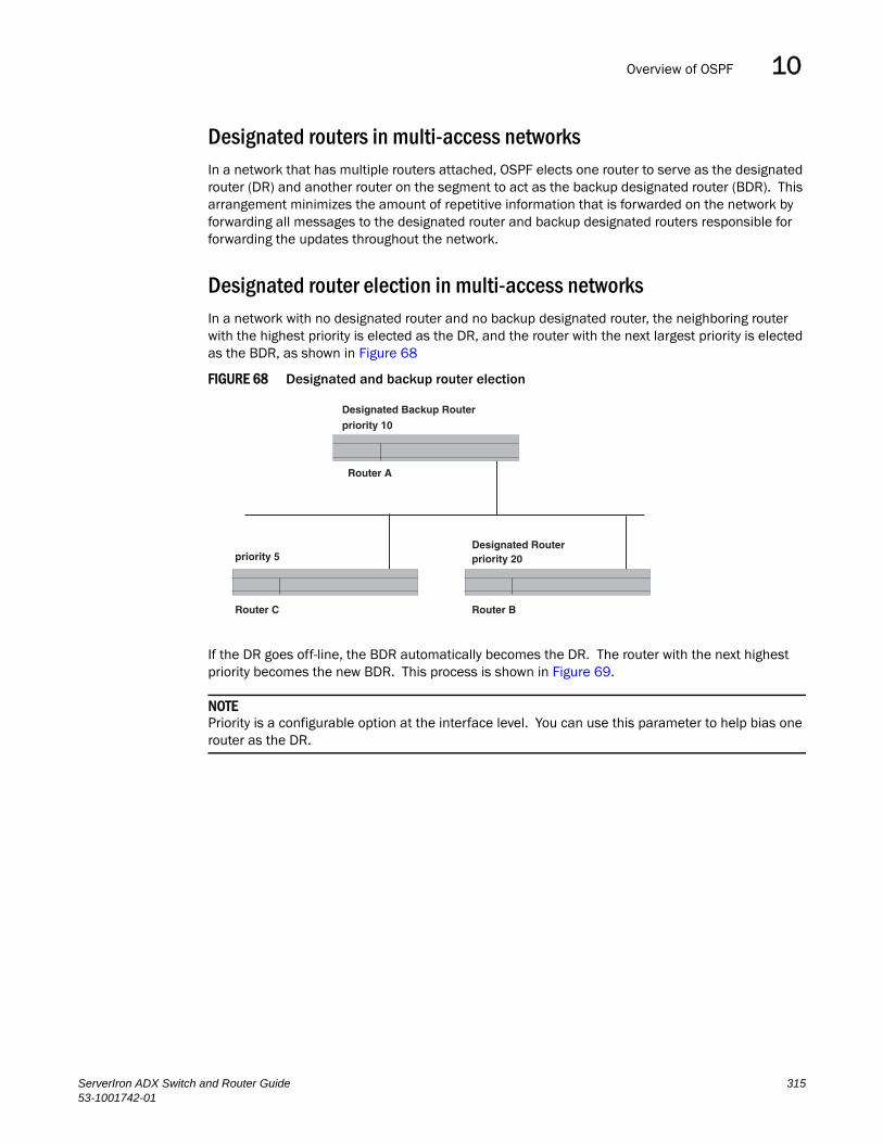
Overview of OSPF 10DRAFT: BROCADE CONFIDENTIAL
Designated routers in multi-access networksIn a network that has multiple routers attached, OSPF elects one router to serve as the designated router (DR) and another router on the segment to act as the backup designated router (BDR). This arrangement minimizes the amount of repetitive information that is forwarded on the network by forwarding all messages to the designated router and backup designated routers responsible for forwarding the updates throughout the network.
Designated router election in multi-access networksIn a network with no designated router and no backup designated router, the neighboring router with the highest priority is elected as the DR, and the router with the next largest priority is elected as the BDR, as shown in Figure 68
FIGURE 68 Designated and backup router election
If the DR goes off-line, the BDR automatically becomes the DR. The router with the next highest priority becomes the new BDR. This process is shown in Figure 69.
NOTEPriority is a configurable option at the interface level. You can use this parameter to help bias one router as the DR.
Designated Backup Router
priority 10
Router A
Router C Router B
priority 5 priority 20Designated Router
ServerIron ADX Switch and Router Guide 31553-1001742-01

Overview of OSPF10DRAFT: BROCADE CONFIDENTIAL
FIGURE 69 Backup designated router becomes designated router
If two neighbors share the same priority, the router with the highest router ID is designated as the DR. The router with the next highest router ID is designated as the BDR.
NOTEBy default, the Brocade router ID is the IP address configured on the lowest numbered loopback interface. If the Layer 3 Switch does not have a loopback interface, the default router ID is the lowest numbered IP address configured on the device. For more information or to change the router ID, refer to “Changing the router ID” on page 239.
When multiple routers on the same network are declaring themselves as DRs, then both priority and router ID are used to select the designated router and backup designated routers.
When only one router on the network claims the DR role despite neighboring routers with higher priorities or router IDs, this router remains the DR. This is also true for BDRs.
The DR and BDR election process is performed when one of the following events occurs:
• an interface is in a waiting state and the wait time expires
• an interface is in a waiting state and a hello packet is received that addresses the BDR
• a change in the neighbor state occurs, such as:
• a neighbor state transitions from 2 or higher
• communication to a neighbor is lost
• a neighbor declares itself to be the DR or BDR for the first time
OSPF RFC 1583 and 2178 complianceBrocade routers are configured, by default, to be compliant with the RFC 1583 OSPF V2 specification. Brocade routers can also be configured to operate with the latest OSPF standard, RFC 2178.
NOTEFor details on how to configure the system to operate with the RFC 2178, refer to “Modify OSPF standard compliance setting” on page 350.
XDesignated Backup Router
Router C
priority 5
Router B
priority 20
Designated Router
priority 10
Router A
316 ServerIron ADX Switch and Router Guide53-1001742-01
Overview of OSPF 10DRAFT: BROCADE CONFIDENTIAL
Reduction of equivalent AS External LSAsAn OSPF ASBR uses AS External link advertisements (AS External LSAs) to originate advertisements of a route to another routing domain, such as a RIP domain. The ASBR advertises the route to the external domain by flooding AS External LSAs to all the other OSPF routers (except those inside stub networks) within the local OSPF Autonomous System (AS).
In some cases, multiple ASBRs in an AS can originate equivalent LSAs. The LSAs are equivalent when they have the same cost, the same next hop, and the same destination. ServerIron ADX optimizes OSPF by eliminating duplicate AS External LSAs in this case. The Layer 3 Switch with the lower router ID flushes the duplicate External LSAs from its database and thus does not flood the duplicate External LSAs into the OSPF AS. AS External LSA reduction therefore reduces the size of the Layer 3 Switch’s link state database.
This enhancement implements the portion of RFC 2328 that describes AS External LSA reduction. This enhancement is enabled by default, requires no configuration, and cannot be disabled.
ServerIron ADX Switch and Router Guide 31753-1001742-01

Overview of OSPF10DRAFT: BROCADE CONFIDENTIAL
Figure 70 shows an example of the AS External LSA reduction feature. In this example, Brocade Layer 3 Switches D and E are OSPF ASBRs, and thus communicate route information between the OSPF AS, which contains Routers A, B, and C, and another routing domain, which contains Router F. The other routing domain is running another routing protocol, such as RIP. Routers D, E, and F, therefore, are each running both OSPF and RIP.
FIGURE 70 AS External LSA reduction
Notice that both Router D and Router E have a route to the other routing domain through Router F. Since both routers are flooding equivalent routes, Routers A, B, and C receive multiple routes with the same cost to the same destination (Router F). For Routers A, B, and C, either route to Router F (through Router D or through Router E) is equally good.
OSPF eliminates the duplicate AS External LSAs. When two or more Brocade Layer 3 Switches configured as ASBRs have equal-cost routes to the same next-hop router in an external routing domain, the ASBR with the highest router ID floods the AS External LSAs for the external domain into the OSPF AS, while the other ASBRs flush the equivalent AS External LSAs from their databases. As a result, the overall volume of route advertisement traffic within the AS is reduced and the Layer 3 Switches that flush the duplicate AS External LSAs have more memory for other OSPF data. In Figure 70, since Router D has a higher router ID than Router E, Router D floods the AS External LSAs for Router F to Routers A, B, and C. Router E flushes the equivalent AS External LSAs from its database.
Router B
Router A
Router C
Router DRouter ID: 2.2.2.2
OSPF Autonomous System (AS)
Router ERouter ID: 1.1.1.1
Routers D, E, and Fare OSPF ASBRs.
Another routing domain(such as RIP)
Router F
318 ServerIron ADX Switch and Router Guide53-1001742-01
Overview of OSPF 10DRAFT: BROCADE CONFIDENTIAL
Algorithm for AS External LSA reduction
Figure 70 shows an example in which the normal AS External LSA reduction feature is in effect. The behavior changes under the following conditions:
• There is one ASBR advertising (originating) a route to the external destination, but one of the following happens:
• A second ASBR comes on-line
• A second ASBR that is already on-line begins advertising an equivalent route to the same destination.
In either case above, the router with the higher router ID floods the AS External LSAs and the other router flushes its equivalent AS External LSAs. For example, if Router D is offline, Router E is the only source for a route to the external routing domain. When Router D comes on-line, it takes over flooding of the AS External LSAs to Router F, while Router E flushes its equivalent AS External LSAs to Router F.
• One of the ASBRs starts advertising a route that is no longer equivalent to the route the other ASBR is advertising. In this case, the ASBRs each flood AS External LSAs. Since the LSAs either no longer have the same cost or no longer have the same next-hop router, the LSAs are no longer equivalent, and the LSA reduction feature no longer applies.
• The ASBR with the higher router ID becomes unavailable or is reconfigured so that it is no longer an ASBR. In this case, the other ASBR floods the AS External LSAs. For example, if Router D goes off-line, then Router E starts flooding the AS with AS External LSAs for the route to Router F.
Support for OSPF RFC 2328 Appendix EServerIron ADX provides support for Appendix E in OSPF RFC 2328. Appendix E describes a method to ensure that an OSPF router (such as a Brocade Layer 3 Switch) generates unique link state IDs for type-5 (External) link state advertisements (LSAs) in cases where two networks have the same network address but different network masks.
NOTESupport for Appendix E of RFC 2328 is enabled automatically and cannot be disabled. No user configuration is required.
Normally, an OSPF router uses the network address alone for the link state ID of the link state advertisement (LSA) for the network. For example, if the router needs to generate an LSA for network 10.1.2.3 255.0.0.0, the router generates ID 10.1.2.3 for the LSA.
However, suppose that an OSPF router needs to generate LSAs for all the following networks:
• 10.0.0.0 255.0.0.0
• 10.0.0.0 255.255.0.0
• 10.0.0.0 255.255.255.0
All three networks have the same network address, 10.0.0.0. Without support for RFC 2328 Appendix E, an OSPF router uses the same link state ID, 10.0.0.0, for the LSAs for all three networks. For example, if the router generates an LSA with ID 10.0.0.0 for network 10.0.0.0 255.0.0.0, this LSA conflicts with the LSA generated for network 10.0.0.0 255.255.0.0 or 10.0.0.0 255.255.255.0. The result is multiple LSAs that have the same ID but that contain different route information.
ServerIron ADX Switch and Router Guide 31953-1001742-01
Overview of OSPF10DRAFT: BROCADE CONFIDENTIAL
When appendix E is supported, the router generates the link state ID for a network as follows.
1. Does an LSA with the network address as its ID already exist?
• No – Use the network address as the ID.
• Yes – Go to step 2.
2. Compare the networks that have the same network address, to determine which network is more specific. The more specific network is the one that has more contiguous one bits in its network mask. For example, network 10.0.0.0 255.255.0.0 is more specific than network 10.0.0.0 255.0.0.0, because the first network has 16 ones bits (255.255.0.0) whereas the second network has only 8 ones bits (255.0.0.0):
• For the less specific network, use the networks address as the ID.
• For the more specific network, use the network’s broadcast address as the ID. The broadcast address is the network address, with all ones bits in the host portion of the address. For example, the broadcast address for network 10.0.0.0 255.255.0.0 is 10.0.0.255.
If this comparison results in a change to the ID of an LSA that has already been generated, the router generates a new LSA to replace the previous one. For example, if the router has already generated an LSA for network with ID 10.0.0.0 for network 10.0.0.0 255.255.255.0, the router must generate a new LSA for the network, if the router needs to generate an LSA for network 10.0.0.0 255.255.0.0 or 10.0.0.0 255.0.0.0.
Dynamic OSPF activation and configurationOSPF is automatically activated when you enable it. The protocol does not require a software reload.
You can configure and save the following OSPF changes without resetting the system:
• all OSPF interface-related parameters (for example: area, hello timer, router dead time cost, priority, re-transmission time, transit delay)
• all area parameters
• all area range parameters
• all virtual-link parameters
• all global parameters
• creation and deletion of an area, interface or virtual link
In addition, you can make the following changes without a system reset by first disabling and then re-enabling OSPF operation:
• changes to address ranges
• changes to global values for redistribution
• addition of new virtual links
You also can change the amount of memory allocated to various types of LSA entries. However, these changes require a system reset or reboot.
320 ServerIron ADX Switch and Router Guide53-1001742-01

Configuring OSPF 10DRAFT: BROCADE CONFIDENTIAL
Dynamic OSPF memoryServerIron ADXr dynamically allocates memory for Link State Advertisements (LSAs) and other OSPF data structures. So long as the Layer 3 Switch has free (unallocated) dynamic memory, OSPF can use the memory.
Configuring OSPFTo begin using OSPF on the router, perform the steps outlined below.
1. Enable OSPF on the router.
2. Assign the areas to which the router will be attached.
3. Assign individual interfaces to the OSPF areas.
4. Define redistribution filters, if desired.
5. Enable redistribution, if you defined redistribution filters.
6. Modify default global and port parameters as required.
7. Modify OSPF standard compliance, if desired.
NOTEOSPF is automatically enabled without a system reset.
Configuration rulesConside the following:
• If a router is to operate as an ASBR, you must enable the ASBR capability at the system level.
• Redistribution must be enabled on routers configured to operate as ASBRs.
• All router ports must be assigned to one of the defined areas on an OSPF router. When a port is assigned to an area, all corresponding subnets on that port are automatically included in the assignment.
OSPF parametersYou can modify or set the following global and interface OSPF parameters:
Global parameters:
• Modify OSPF standard compliance setting.
• Assign an area.
• Define an area range.
• Define the area virtual link.
• Set global default metric for OSPF.
• Change the reference bandwidth for the default cost of OSPF interfaces.
• Disable or re-enable load sharing.
ServerIron ADX Switch and Router Guide 32153-1001742-01

Configuring OSPF10DRAFT: BROCADE CONFIDENTIAL
• Enable or disable default-information-originate.
• Modify Shortest Path First (SPF) timers
• Define external route summarization
• Define redistribution metric type.
• Define deny redistribution.
• Define permit redistribution.
• Enable redistribution.
• Change the LSA pacing interval.
• Modify OSPF Traps generated.
• Modify database overflow interval.
• Enable and configure graceful restart
Interface parameters:
• Assign interfaces to an area.
• Define the authentication key for the interface.
• Change the authentication-change interval
• Modify the cost for a link.
• Modify the dead interval.
• Modify MD5 authentication key parameters.
• Modify the priority of the interface.
• Modify the retransmit interval for the interface.
• Modify the transit delay of the interface.
NOTEWhen using the CLI, you set global level parameters at the OSPF CONFIG Level of the CLI. To reach that level, enter router ospf… at the global CONFIG Level. Interface parameters for OSPF are set at the interface CONFIG Level using the CLI command, ip ospf…
When using the Web management interface, you set OSPF global parameters using the OSPF configuration panel. All other parameters are accessed through links accessed from the OSPF configuration sheet.
Enable OSPF on the routerWhen you enable OSPF on the router, the protocol is automatically activated. To enable OSPF on the router, use the following method.
ServerIron(config)# router ospf
This command launches you into the OSPF router level where you can assign areas and modify OSPF global parameters.
322 ServerIron ADX Switch and Router Guide53-1001742-01
Configuring OSPF 10DRAFT: BROCADE CONFIDENTIAL
Note regarding disabling OSPF
If you disable OSPF, the Layer 3 Switch removes all the configuration information for the disabled protocol from the running-config. Moreover, when you save the configuration to the startup-config file after disabling one of these protocols, all the configuration information for the disabled protocol is removed from the startup-config file.
The CLI displays a warning message such as the following.
ServerIron(config-ospf-router)# no router ospfrouter ospf mode now disabled. All ospf config data will be lost when writing to flash!
If you have disabled the protocol but have not yet saved the configuration to the startup-config file and reloaded the software, you can restore the configuration information by re-entering the command to enable the protocol (ex: router ospf), or by selecting the Web management option to enable the protocol. If you have already saved the configuration to the startup-config file and reloaded the software, the information is gone.
If you are testing an OSPF configuration and are likely to disable and re-enable the protocol, you might want to make a backup copy of the startup-config file containing the protocol’s configuration information. This way, if you remove the configuration information by saving the configuration after disabling the protocol, you can restore the configuration by copying the backup copy of the startup-config file onto the flash memory.
Assign OSPF areasOnce OSPF is enabled on the system, you can assign areas. Assign an IP address or number as the area ID for each area. The area ID is representative of all IP addresses (subnets) on a router port. Each port on a router can support one area.
An area can be normal, a stub, or a Not-So-Stubby Area (NSSA).
• Normal – OSPF routers within a normal area can send and receive External Link State Advertisements (LSAs).
• Stub – OSPF routers within a stub area cannot send or receive External LSAs. In addition, OSPF routers in a stub area must use a default route to the area’s Area Border Router (ABR) or Autonomous System Boundary Router (ASBR) to send traffic out of the area.
• NSSA – The ASBR of an NSSA can import external route information into the area:
• ASBRs redistribute (import) external routes into the NSSA as type 7 LSAs. Type-7 External LSAs are a special type of LSA generated only by ASBRs within an NSSA, and are flooded to all the routers within only that NSSA.
• ABRs translate type 7 LSAs into type 5 External LSAs, which can then be flooded throughout the AS. You can configure address ranges on the ABR of an NSSA so that the ABR converts multiple type-7 External LSAs received from the NSSA into a single type-5 External LSA.
When an NSSA contains more than one ABR, OSPF elects one of the ABRs to perform the LSA translation for NSSA. OSPF elects the ABR with the highest router ID. If the elected ABR becomes unavailable, OSPF automatically elects the ABR with the next highest router ID to take over translation of LSAs for the NSSA. The election process for NSSA ABRs is automatic.
ServerIron ADX Switch and Router Guide 32353-1001742-01

Configuring OSPF10DRAFT: BROCADE CONFIDENTIAL
Example
To set up the OSPF areas shown in Figure 67 on page 314, use the following method.
ServerIron(config-ospf-router)# area 192.5.1.0 ServerIron(config-ospf-router)# area 200.5.0.0 ServerIron(config-ospf-router)# area 195.5.0.0ServerIron(config-ospf-router)# area 0.0.0.0ServerIron(config-ospf-router) write memory
Syntax: area <num> | <ip-addr>
The <num> | <ip-addr> parameter specifies the area number, which can be a number or in IP address format. If you specify an number, the number can be from 0 – 2,147,483,647.
NOTEYou can assign one area on a router interface. For example, if the system or chassis module has 16 ports, 16 areas are supported on the chassis or module.
Assign a totally stubby area
By default, the Layer 3 Switch sends summary LSAs (LSA type 3) into stub areas. You can further reduce the number of link state advertisements (LSA) sent into a stub area by configuring the Layer 3 Switch to stop sending summary LSAs (type 3 LSAs) into the area. You can disable the summary LSAs when you are configuring the stub area or later after you have configured the area.
This feature disables origination of summary LSAs, but the Layer 3 Switch still accepts summary LSAs from OSPF neighbors and floods them to other neighbors. The Layer 3 Switch can form adjacencies with other routers regardless of whether summarization is enabled or disabled for areas on each router.
When you enter a command or apply a Web management option to disable the summary LSAs, the change takes effect immediately. If you apply the option to a previously configured area, the Layer 3 Switch flushes all of the summary LSAs it has generated (as an ABR) from the area.
NOTEThis feature applies only when the Layer 3 Switch is configured as an Area Border Router (ABR) for the area. To completely prevent summary LSAs from being sent to the area, disable the summary LSAs on each OSPF router that is an ABR for the area.
This feature does not apply to Not So Stubby Areas (NSSAs).
To disable summary LSAs for a stub area, enter commands such as the following.
ServerIron(config-ospf-router)# area 40 stub 99 no-summary
Syntax: area <num> | <ip-addr> stub <cost> [no-summary]
The <num> | <ip-addr> parameter specifies the area number, which can be a number or in IP address format. If you specify a number, the number can be from 0 – 2,147,483,647.
The stub <cost> parameter specifies an additional cost for using a route to or from this area and can be from 1 – 16777215. There is no default. Normal areas do not use the cost parameter.
The no-summary parameter applies only to stub areas and disables summary LSAs from being sent into the area.
324 ServerIron ADX Switch and Router Guide53-1001742-01

Configuring OSPF 10DRAFT: BROCADE CONFIDENTIAL
NOTEYou can assign one area on a router interface. For example, if the system or chassis module has 16 ports, 16 areas are supported on the chassis or module.
Assign a Not-So-Stubby Area (NSSA)
The OSPF Not So Stubby Area (NSSA) feature enables you to configure OSPF areas that provide the benefits of stub areas, but that also are capable of importing external route information. OSPF does not flood external routes from other areas into an NSSA, but does translate and flood route information from the NSSA into other areas such as the backbone.
NSSAs are especially useful when you want to summarize Type-5 External LSAs (external routes) before forwarding them into an OSPF area. The OSPF specification (RFC 2328) prohibits summarization of Type-5 LSAs and requires OSPF to flood Type-5 LSAs throughout a routing domain. When you configure an NSSA, you can specify an address range for aggregating the external routes that the NSSA's ABR exports into other areas.
The Brocade implementation of NSSA is based on RFC 1587.
Figure 71 shows an example of an OSPF network containing an NSSA.
FIGURE 71 OSPF network containing an NSSA
This example shows two routing domains, a RIP domain and an OSPF domain. The ASBR inside the NSSA imports external routes from RIP into the NSSA as Type-7 LSAs, which the ASBR floods throughout the NSSA.
RIP Domain
NSSA Area 1.1.1.1
Internal ASBR OSPF ABR
OSPF Area 0Backbone
ServerIron ADX Switch and Router Guide 32553-1001742-01

Configuring OSPF10DRAFT: BROCADE CONFIDENTIAL
The ABR translates the Type-7 LSAs into Type-5 LSAs. If an area range is configured for the NSSA, the ABR also summarizes the LSAs into an aggregate LSA before flooding the Type-5 LSA(s) into the backbone.
Since the NSSA is partially “stubby” the ABR does not flood external LSAs from the backbone into the NSSA. To provide access to the rest of the Autonomous System (AS), the ABR generates a default Type-7 LSA into the NSSA.
Configuring an NSSATo configure OSPF area 1.1.1.1 as an NSSA, enter the following commands.
ServerIron(config)# router ospfServerIron(config-ospf-router)# area 1.1.1.1 nssa 1 ServerIron(config-ospf-router)# write memory
Syntax: area <num> | <ip-addr> nssa <cost> | default-information-originate
The <num> | <ip-addr> parameter specifies the area number, which can be a number or in IP address format. If you specify an number, the number can be from 0 – 2,147,483,647.
The nssa <cost> | default-information-originate parameter specifies that this is a Not-So-Stubby-Area (NSSA). The <cost> specifies an additional cost for using a route to or from this NSSA and can be from 1 – 16777215. There is no default. Normal areas do not use the cost parameter. Alternatively, you can use the default-information-originate parameter causes the Layer 3 Switch to inject the default route into the NSSA.
NOTEThe Layer 3 Switch does not inject the default route into an NSSA by default.
NOTEYou can assign one area on a router interface. For example, if the system or chassis module has 16 ports, 16 areas are supported on the chassis or module.
To configure additional parameters for OSPF interfaces in the NSSA, use the ip ospf area… command at the interface level of the CLI.
Configuring an address range for the NSSAIf you want the ABR that connects the NSSA to other areas to summarize the routes in the NSSA before translating them into Type-5 LSAs and flooding them into the other areas, configure an address range. The ABR creates an aggregate value based on the address range. The aggregate value becomes the address that the ABR advertises instead of advertising the individual addresses represented by the aggregate. You can configure up to 32 ranges in an OSPF area.
To configure an address range in NSSA 1.1.1.1, enter the following commands. This example assumes that you have already configured NSSA 1.1.1.1.
ServerIron(config)# router ospfServerIron(config-ospf-router)# area 1.1.1.1 range 209.157.22.1 255.255.0.0ServerIron(config-ospf-router)# write memory
Syntax: [no] area <num> | <ip-addr> range <ip-addr> <ip-mask> [advertise | not-advertise]
The <num> | <ip-addr> parameter specifies the area number, which can be in IP address format. If you specify a number, the number can be from 0 – 2,147,483,647.
326 ServerIron ADX Switch and Router Guide53-1001742-01
Configuring OSPF 10DRAFT: BROCADE CONFIDENTIAL
The range <ip-addr> parameter specifies the IP address portion of the range. The software compares the address with the significant bits in the mask. All network addresses that match this comparison are summarized in a single route advertised by the router.
The <ip-mask> parameter specifies the portions of the IP address that a route must contain to be summarized in the summary route. In the example above, all networks that begin with 209.157 are summarized into a single route.
The advertise | not-advertise parameter specifies whether you want the Layer 3 Switch to send type 3 LSAs for the specified range in this area. The default is advertise.
Assigning an area range (optional)You can assign a range for an area, but it is not required. Ranges allow a specific IP address and mask to represent a range of IP addresses within an area, so that only that reference range address is advertised to the network, instead of all the addresses within that range. Each area can have up to 32 range addresses.
Example
To define an area range for subnets on 193.45.5.1 and 193.45.6.2, enter the following command.
ServerIron(config)# router ospfServerIron(config-ospf-router)# area 192.45.5.1 range 193.45.0.0 255.255.0.0ServerIron(config-ospf-router)# area 193.45.6.2 range 193.45.0.0 255.255.0.0
Syntax: area <num> | <ip-addr> range <ip-addr> <ip-mask>
The <num> | <ip-addr> parameter specifies the area number, which can be in IP address format.
The range <ip-addr> parameter specifies the IP address portion of the range. The software compares the address with the significant bits in the mask. All network addresses that match this comparison are summarized in a single route advertised by the router.
The <ip-mask> parameter specifies the portions of the IP address that a route must contain to be summarized in the summary route. In the example above, all networks that begin with 193.45 are summarized into a single route.
Assigning interfaces to an areaOnce you define OSPF areas, you can assign interfaces the areas. All router ports must be assigned to one of the defined areas on an OSPF router. When a port is assigned to an area, all corresponding subnets on that port are automatically included in the assignment.
To assign interface 1/8 of Router A to area 192.5.0.0 and then save the changes, enter the following commands.
RouterA(config-ospf-router)# interface e 1/8RouterA(config-if-1/8)# ip ospf area 192.5.0.0RouterA(config-if-1/8)# write memory
Modify interface defaultsOSPF has interface parameters that you can configure. For simplicity, each of these parameters has a default value. No change to these default values is required except as needed for specific network configurations.
ServerIron ADX Switch and Router Guide 32753-1001742-01
Configuring OSPF10DRAFT: BROCADE CONFIDENTIAL
Port default values can be modified using the following CLI commands at the interface configuration level of the CLI:
• ip ospf area <ip-addr>
• ip ospf auth-change-wait-time <secs>
• ip ospf authentication-key [0 | 1] <string>
• ip ospf cost <num>
• ip ospf dead-interval <value>
• ip ospf hello-interval <value>
• ip ospf md5-authentication key-activation-wait-time <num> | key-id <num> [0 | 1] key <string>
• ip ospf passive
• ip ospf priority <value>
• ip ospf retransmit-interval <value>
• ip ospf transmit-delay <value>
For a complete description of these parameters, refer to the summary of OSPF port parameters in the next section.
OSPF interface parameters
The following parameters apply to OSPF interfaces.
Area: Assigns an interface to a specific area. You can assign either an IP address or number to represent an OSPF Area ID. If you assign a number, it can be any value from 0 – 2,147,483,647.
Auth-change-wait-time: OSPF gracefully implements authentication changes to allow all routers to implement the change and thus prevent disruption to neighbor adjacencies. During the authentication-change interval, both the old and new authentication information is supported. The default authentication-change interval is 300 seconds (5 minutes). You change the interval to a value from 0 – 14400 seconds.
Authentication-key: OSPF supports three methods of authentication for each interface—none, simple password, and MD5. Only one method of authentication can be active on an interface at a time. The default authentication value is none, meaning no authentication is performed:
• The simple password method of authentication requires you to configure an alphanumeric password on an interface. The simple password setting takes effect immediately. All OSPF packets transmitted on the interface contain this password. Any OSPF packet received on the interface is checked for this password. If the password is not present, then the packet is dropped. The password can be up to eight characters long.
• The MD5 method of authentication requires you to configure a key ID and an MD5 Key. The key ID is a number from 1 – 255 and identifies the MD5 key that is being used. The MD5 key can be up to sixteen alphanumeric characters long.
Cost: Indicates the overhead required to send a packet across an interface. You can modify the cost to differentiate between 100 Mbps and 1000 Mbps (1 Gbps) links. The default cost is calculated by dividing 100 million by the bandwidth. For 10 Mbps links, the cost is 10. The cost for both 100 Mbps and 1000 Mbps links is 1, because the speed of 1000 Mbps was not in use at the time the OSPF cost formula was devised.
328 ServerIron ADX Switch and Router Guide53-1001742-01
Configuring OSPF 10DRAFT: BROCADE CONFIDENTIAL
Dead-interval: Indicates the number of seconds that a neighbor router waits for a hello packet from the current router before declaring the router down. The value can be from 1 – 65535 seconds. The default is 40 seconds.
Hello-interval: Represents the length of time between the transmission of hello packets. The value can be from 1 – 65535 seconds. The default is 10 seconds.
MD5-authentication activation wait time: The number of seconds the Layer 3 Switch waits until placing a new MD5 key into effect. The wait time provides a way to gracefully transition from one MD5 key to another without disturbing the network. The wait time can be from 0 – 14400 seconds. The default is 300 seconds (5 minutes).
MD5-authentication key ID and key: A method of authentication that requires you to configure a key ID and an MD5 key. The key ID is a number from 1 – 255 and identifies the MD5 key that is being used. The MD5 key consists of up to 16 alphanumeric characters. The MD5 is encrypted and included in each OSPF packet transmitted.
Passive: When you configure an OSPF interface to be passive, that interface does not send or receive OSPF route updates. By default, all OSPF interfaces are active and thus can send and receive OSPF route information. Since a passive interface does not send or receive route information, the interface is in effect a stub network. OSPF interfaces are active by default.
NOTEThis option affects all IP subnets configured on the interface. If you want to disable OSPF updates only on some of the IP subnets on the interface, use the ospf-ignore or ospf-passive parameter with the ip address command. Refer to “Assigning an IP address to an Ethernet port” on page 232.
Priority: Allows you to modify the priority of an OSPF router. The priority is used when selecting the designated router (DR) and backup designated routers (BDRs). The value can be from 0 – 255. The default is 1. If you set the priority to 0, the Layer 3 Switch does not participate in DR and BDR election.
Retransmit-interval: The time between retransmissions of link-state advertisements (LSAs) to adjacent routers for this interface. The value can be from 0 – 3600 seconds. The default is 5 seconds.
Transit-delay: The time it takes to transmit Link State Update packets on this interface. The value can be from 0 – 3600 seconds. The default is 1 second.
Encrypted display of the authentication string or MD5 authentication keyThe optional 0 | 1 parameter with the authentication-key and md5-authentication key-id parameters affects encryption.
For added security display of the password or authentication string is encrypted. Encryption is enabled by default. The software also provides an optional parameter to disable encryption of a password or authentication string, on an individual OSPF area or OSPF interface basis.
When encryption of the passwords or authentication strings is enabled, they are encrypted in the CLI regardless of the access level you are using. In the Web management interface, the passwords or authentication strings are encrypted at the read-only access level but are visible at the read-write access level.
The encryption option can be omitted (the default) or can be one of the following:
ServerIron ADX Switch and Router Guide 32953-1001742-01

Configuring OSPF10DRAFT: BROCADE CONFIDENTIAL
• 0 – Disables encryption for the password or authentication string you specify with the command. The password or string is shown as clear text in the running-config and the startup-config file. Use this option of you do not want display of the password or string to be encrypted.
• 1 – Assumes that the password or authentication string you enter is the encrypted form, and decrypts the value before using it.
NOTEIf you want the software to assume that the value you enter is the clear-text form, and to encrypt display of that form, do not enter 0 or 1. Instead, omit the encryption option and allow the software to use the default behavior.
If you specify encryption option 1, the software assumes that you are entering the encrypted form of the password or authentication string. In this case, the software decrypts the password or string you enter before using the value for authentication. If you accidentally enter option 1 followed by the clear-text version of the password or string, authentication will fail because the value used by the software will not match the value you intended to use.
Change the timer for OSPF authentication changesWhen you make an OSPF authentication change, the software uses the authentication-change timer to gracefully implement the change. The software implements the change in the following ways:
• Outgoing OSPF packets – After you make the change, the software continues to use the old authentication to send packets, during the remainder of the current authentication-change interval. After this, the software uses the new authentication for sending packets.
• Inbound OSPF packets – The software accepts packets containing the new authentication and continues to accept packets containing the older authentication for two authentication-change intervals. After the second interval ends, the software accepts packets only if they contain the new authentication key.
The default authentication-change interval is 300 seconds (5 minutes). You change the interval to a value from 0 – 14400 seconds.
OSPF provides graceful authentication change for all the following types of authentication changes in OSPF:
• Changing authentication methods from one of the following to another of the following:
• Simple text password
• MD5 authentication
• No authentication
• Configuring a new simple text password or MD5 authentication key
• Changing an existing simple text password or MD5 authentication key
To change the authentication-change interval, enter a command such as the following at the interface configuration level of the CLI.
ServerIron(config-if-2/5)# ip ospf auth-change-wait-time 400
Syntax: [no] ip ospf auth-change-wait-time <secs>
330 ServerIron ADX Switch and Router Guide53-1001742-01

Configuring OSPF 10DRAFT: BROCADE CONFIDENTIAL
The <secs> parameter specifies the interval and can be from 0 – 14400 seconds. The default is 300 seconds (5 minutes).
NOTEFor backward compatibility, the ip ospf md5-authentication key-activation-wait-time <seconds> command is still supported.
Block flooding of outbound LSAs on specific OSPF interfacesBy default, the Layer 3 Switch floods all outbound LSAs on all the OSPF interfaces within an area. You can configure a filter to block outbound LSAs on an OSPF interface. This feature is particularly useful when you want to block LSAs from some, but not all, of the interfaces attached to the area.
After you apply filters to block the outbound LSAs, the filtering occurs during the database synchronization and flooding.
If you remove the filters, the blocked LSAs are automatically re-flooded. You do not need to reset OSPF to re-flood the LSAs.
NOTEYou cannot block LSAs on virtual links.
To apply a filter to an OSPF interface to block flooding of outbound LSAs on the interface, enter the following command at the Interface configuration level for that interface.
ServerIron(config-if-1/1)# ip ospf database-filter all out
The command in this example blocks all outbound LSAs on the OSPF interface configured on port 1/1.
Syntax: [no] ip ospf database-filter all out
To remove the filter, enter a command such as the following.
ServerIron(config-if-1/1)# no ip ospf database-filter all out
Assign virtual linksAll ABRs (area border routers) must have either a direct or indirect link to the OSPF backbone area (0.0.0.0 or 0). If an ABR does not have a physical link to the area backbone, the ABR can configure a virtual link to another router within the same area, which has a physical connection to the area backbone.
The path for a virtual link is through an area shared by the neighbor ABR (router with a physical backbone connection), and the ABR requiring a logical connection to the backbone.
Two parameters fields must be defined for all virtual links—transit area ID and neighbor router.
• The transit area ID represents the shared area of the two ABRs and serves as the connection point between the two routers. This number should match the area ID value.
• The neighbor router field is the router ID (IP address) of the router that is physically connected to the backbone, when assigned from the router interface requiring a logical connection. When assigning the parameters from the router with the physical connection, the router ID is the IP address of the router requiring a logical connection to the backbone.
ServerIron ADX Switch and Router Guide 33153-1001742-01

Configuring OSPF10DRAFT: BROCADE CONFIDENTIAL
NOTEBy default, the Brocade router ID is the IP address configured on the lowest numbered loopback interface. If the Layer 3 Switch does not have a loopback interface, the default router ID is the lowest numbered IP address configured on the device. For more information or to change the router ID, refer to “Changing the router ID” on page 239.
NOTEWhen you establish an area virtual link, you must configure it on both of the routers (both ends of the virtual link).
FIGURE 72 Defining OSPF virtual links within a network
Example
Figure 72 shows an OSPF area border router, RouterA, that is cut off from the backbone area (area 0). To provide backbone access to RouterA, you can add a virtual link between RouterA and RouterC using area 1 as a transit area. To configure the virtual link, you define the link on the router that is at each end of the link. No configuration for the virtual link is required on the routers in the transit area.
To define the virtual link on RouterA, enter the following commands.
RouterA(config-ospf-router)# area 1 virtual-link 209.157.22.1RouterA(config-ospf-router)# write memory
Enter the following commands to configure the virtual link on RouterC.
OSPF Area 0
OSPF Area 1“transit area”
OSPF Area 2
Router CRouter ID 209.157.22.1
Router B Router ARouter ID 10.0.0.1
332 ServerIron ADX Switch and Router Guide53-1001742-01

Configuring OSPF 10DRAFT: BROCADE CONFIDENTIAL
RouterC(config-ospf-router)# area 1 virtual-link 10.0.0.1 RouterC(config-ospf-router)# write memory
Syntax: area <ip-addr> | <num> virtual-link <router-id>[authentication-key | dead-interval | hello-interval | retransmit-interval | transmit-delay <value>]
The area <ip-addr> | <num> parameter specifies the transit area.
The <router-id> parameter specifies the router ID of the OSPF router at the remote end of the virtual link. To display the router ID on a Brocade Layer 3 Switch, enter the show ip command.
Refer to “Modify virtual link parameters” on page 333 for descriptions of the optional parameters.
Modify virtual link parametersOSPF has some parameters that you can modify for virtual links. Notice that these are the same parameters as the ones you can modify for physical interfaces.
You can modify default values for virtual links using the following CLI command at the OSPF router level of the CLI, as shown in the following syntax.
Syntax: area <num> | <ip-addr> virtual-link <ip-addr> [authentication-key [0 | 1] <string>] [dead-interval <num>] [hello-interval <num>] [md5-authentication key-activation-wait-time <num> | key-id <num> [0 | 1] key <string>][retransmit-interval <num>] [transmit-delay <num>]
Virtual link parameter descriptions
You can modify the following virtual link interface parameters.
Authentication Key: This parameter allows you to assign different authentication methods on a port-by-port basis. OSPF supports three methods of authentication for each interface—none, simple password, and MD5. Only one method of authentication can be active on an interface at a time.
The simple password method of authentication requires you to configure an alphanumeric password on an interface. The password can be up to eight characters long. The simple password setting takes effect immediately. All OSPF packets transmitted on the interface contain this password. All OSPF packets received on the interface are checked for this password. If the password is not present, then the packet is dropped.
The MD5 method of authentication encrypts the authentication key you define. The authentication is included in each OSPF packet transmitted.
MD5 Authentication Key: When simple authentication is enabled, the key is an alphanumeric password of up to eight characters. When MD5 is enabled, the key is an alphanumeric password of up to 16 characters that is later encrypted and included in each OSPF packet transmitted. You must enter a password in this field when the system is configured to operate with either simple or MD5 authentication.
MD5 Authentication Key ID: The Key ID is a number from 1 – 255 and identifies the MD5 key that is being used. This parameter is required to differentiate among multiple keys defined on a router.
ServerIron ADX Switch and Router Guide 33353-1001742-01

Configuring OSPF10DRAFT: BROCADE CONFIDENTIAL
MD5 Authentication Wait Time: This parameter determines when a newly configured MD5 authentication key is valid. This parameter provides a graceful transition from one MD5 key to another without disturbing the network. All new packets transmitted after the key activation wait time interval use the newly configured MD5 Key. OSPF packets that contain the old MD5 key are accepted for up to five minutes after the new MD5 key is in operation.
The range for the key activation wait time is from 0 – 14400 seconds. The default value is 300 seconds.
Hello Interval: The length of time between the transmission of hello packets. The range is 1 – 65535 seconds. The default is 10 seconds.
Retransmit Interval: The interval between the re-transmission of link state advertisements to router adjacencies for this interface. The range is 0 – 3600 seconds. The default is 5 seconds.
Transmit Delay: The period of time it takes to transmit Link State Update packets on the interface. The range is 0 – 3600 seconds. The default is 1 second.
Dead Interval: The number of seconds that a neighbor router waits for a hello packet from the current router before declaring the router down. The range is 1 – 65535 seconds. The default is 40 seconds.
Encrypted display of the authentication string or MD5 authentication keyThe optional 0 | 1 parameter with the authentication-key and md5-authentication key-id parameters affects encryption.
For added security, the display of the password or authentication string is encrypted. Encryption is enabled by default. The software also provides an optional parameter to disable encryption of a password or authentication string, on an individual OSPF area or OSPF interface basis.
When encryption of the passwords or authentication strings is enabled, they are encrypted in the CLI regardless of the access level you are using. In the Web management interface, the passwords or authentication strings are encrypted at the read-only access level but are visible at the read-write access level.
The encryption option can be omitted (the default) or can be one of the following:
• 0 – Disables encryption for the password or authentication string you specify with the command. The password or string is shown as clear text in the running-config and the startup-config file. Use this option of you do not want display of the password or string to be encrypted.
• 1 – Assumes that the password or authentication string you enter is the encrypted form, and decrypts the value before using it.
NOTEIf you want the software to assume that the value you enter is the clear-text form, and to encrypt display of that form, do not enter 0 or 1. Instead, omit the encryption option and allow the software to use the default behavior.
If you specify encryption option 1, the software assumes that you are entering the encrypted form of the password or authentication string. In this case, the software decrypts the password or string you enter before using the value for authentication. If you accidentally enter option 1 followed by the clear-text version of the password or string, authentication will fail because the value used by the software will not match the value you intended to use.
334 ServerIron ADX Switch and Router Guide53-1001742-01

Configuring OSPF 10DRAFT: BROCADE CONFIDENTIAL
Changing the reference bandwidth for the cost on OSPF interfacesEach interface on which OSPF is enabled has a cost associated with it. The Layer 3 Switch advertises its interfaces and their costs to OSPF neighbors. For example, if an interface has an OSPF cost of ten, the Layer 3 Switch advertises the interface with a cost of ten to other OSPF routers.
By default, an interface’s OSPF cost is based on the port speed of the interface. The cost is calculated by dividing the reference bandwidth by the port speed. The default reference bandwidth is 100 Mbps, which results in the following default costs:
• 10 Mbps port – 10
• All other port speeds – 1
You can change the reference bandwidth, to change the costs calculated by the software.
The software uses the following formula to calculate the cost.
Cost = reference-bandwidth/interface-speed
If the resulting cost is less than 1, the software rounds the cost up to 1. The default reference bandwidth results in the following costs:
• 10 Mbps port’s cost = 100/10 = 10
• 100 Mbps port’s cost = 100/100 = 1
• 1000 Mbps port’s cost = 100/1000 = 0.10, which is rounded up to 1
• 155 Mbps port’s cost = 100/155 = 0.65, which is rounded up to 1
• 622 Mbps port’s cost = 100/622 = 0.16, which is rounded up to 1
• 2488 Mbps port’s cost = 100/2488 = 0.04, which is rounded up to 1
The bandwidth for interfaces that consist of more than one physical port is calculated as follows:
• Trunk group – The combined bandwidth of all the ports.
• Virtual interface – The combined bandwidth of all the ports in the port-based VLAN that contains the virtual interface.
The default reference bandwidth is 100 Mbps. You can change the reference bandwidth to a value from 1 – 4294967.
If a change to the reference bandwidth results in a cost change to an interface, the Layer 3 Switch sends a link-state update to update the costs of interfaces advertised by the Layer 3 Switch.
NOTEIf you specify the cost for an individual interface, the cost you specify overrides the cost calculated by the software.
Interface types to which the reference bandwidth does not apply
Some interface types are not affected by the reference bandwidth and always have the same cost regardless of the reference bandwidth in use:
• The cost of a loopback interface is always 0.
• The cost of a virtual link is calculated using the Shortest Path First (SPF) algorithm and is not affected by the auto-cost feature.
ServerIron ADX Switch and Router Guide 33553-1001742-01

Configuring OSPF10DRAFT: BROCADE CONFIDENTIAL
• The bandwidth for tunnel interfaces is 9 Kbps and is not affected by the auto-cost feature.
Changing the reference bandwidth
To change reference bandwidth, use the following CLI method.
To change the reference bandwidth, enter a command such as the following at the OSPF configuration level of the CLI.
ServerIron(config-ospf-router)# auto-cost reference-bandwidth 500
The reference bandwidth specified in this example results in the following costs:
• 10 Mbps port’s cost = 500/10 = 50
• 100 Mbps port’s cost = 500/100 = 5
• 1000 Mbps port’s cost = 500/1000 = 0.5, which is rounded up to 1
• 155 Mbps port’s cost = 500/155 = 3.23, which is rounded up to 4
• 622 Mbps port’s cost = 500/622 = 0.80, which is rounded up to 1
• 2488 Mbps port’s cost = 500/2488 = 0.20, which is rounded up to 1
The costs for 10 Mbps, 100 Mbps, and 155 Mbps ports change as a result of the changed reference bandwidth. Costs for higher-speed interfaces remain the same.
Syntax: [no] auto-cost reference-bandwidth <num>
The <num> parameter specifies the reference bandwidth and can be a value from 1 – 4294967. The default is 100, which results in the same costs as previous software releases.
To restore the reference bandwidth to its default value and thus restore the default costs of interfaces to their default values, enter the following command.
ServerIron(config-ospf-router)# no auto-cost reference-bandwidth
Define redistribution filtersRoute redistribution imports and translates different protocol routes into a specified protocol type. On Brocade routers, redistribution is supported for static routes, OSPF and, RIP. When you configure redistribution for RIP, you can specify that static or OSPF routes are imported into RIP routes. Likewise, OSPF redistribution supports the import of static and RIP, routes into OSPF routes.
In Figure 73 on page 337, an administrator wants to configure the Layer 3 Switch acting as the ASBR (Autonomous System Boundary Router) between the RIP domain and the OSPF domain to redistribute routes between the two domains.
NOTEThe ASBR must be running both RIP and OSPF protocols to support this activity.
To configure for redistribution, define the redistribution tables with deny and permit redistribution filters.
• If you are using the CLI, use the deny and permit redistribute commands for OSPF at the OSPF router level.
• If you are using the Web management interface, click on the plus sign next to Configure in the tree view, click on the plus sign next to OSPF, then select the Redistribution Filter link from the OSPF configuration sheet.
336 ServerIron ADX Switch and Router Guide53-1001742-01

Configuring OSPF 10DRAFT: BROCADE CONFIDENTIAL
NOTEDo not enable redistribution until you have configured the redistribution filters. If you enable redistribution before you configure the redistribution filters, the filters will not take affect and all routes will be distributed.
FIGURE 73 Redistributing OSPF and static routes to RIP routes
Example
To configure the Layer 3 Switch acting as an ASBR in Figure 73 to redistribute OSPF and static routes into RIP, enter the following commands.
ServerIronASBR(config)# router ripServerIronASBR(config-rip-router)# permit redistribute 1 allServerIronASBR(config-rip-router)# write memory
NOTERedistribution is permitted for all routes by default, so the permit redistribute 1 all command in the example above is shown for clarity but is not required.
RIP Domain
OSPF Domain
ASBR (Autonomous System Border Router)
ServerIron ADX Switch and Router Guide 33753-1001742-01

Configuring OSPF10DRAFT: BROCADE CONFIDENTIAL
You also have the option of specifying import of just OSPF or static routes, as well as specifying that only routes for a specific network or with a specific cost (metric) be imported, as shown in the command syntax below.
Syntax: deny | permit redistribute <filter-num> all | connected | rip | static[address <ip-addr> <ip-mask> [match-metric <value> [set-metric <value>]]]
Example
To redistribute RIP and static routes into OSPF, enter the following commands on the Layer 3 Switch acting as an ASBR.
ServerIronASBR(config)# router ospfServerIronASBR(config-ospf-router)# permit redistribute 1 allServerIronASBR(config-ospf-router)# write memory
Syntax: deny | permit redistribute <filter-num> all | connected | rip | staticaddress <ip-addr> <ip-mask> [match-metric <value> | set-metric <value>]
NOTERedistribution is permitted for all routes by default, so the permit redistribute 1 all command in the example above is shown for clarity but is not required.
You also have the option of specifying import of just OSPF or static routes, as well as specifying that only routes for a specific network or with a specific cost (metric) be imported, as shown in the command syntax below.
Syntax: [no] redistribution connected | rip | static [route-map <map-name>]
For example, to enable redistribution of RIP and static IP routes into OSPF, enter the following commands.
ServerIron(config)# router ospfServerIron(config-ospf-router)# redistribution ripServerIron(config-ospf-router)# redistribution staticServerIron(config-ospf-router)# write memory
NOTEThe redistribution command does not perform the same function as the permit redistribute and deny redistribute commands. The redistribute commands allow you to control redistribution of routes by filtering on the IP address and network mask of a route. The redistribution commands enable redistribution for routes of specific types (static, directly connected, and so on). Configure all your redistribution filters before enabling redistribution.
NOTEDo not enable redistribution until you have configured the redistribution filters. If you enable redistribution before you configure the redistribution filters, the filters will not take affect and all routes will be distributed.
Prevent specific OSPF routes from being installed in the IP route tableBy default, all OSPF routes in the OSPF route table are eligible for installation in the IP route table. You can configure a distribution list to explicitly deny specific routes from being eligible for installation in the IP route table.
338 ServerIron ADX Switch and Router Guide53-1001742-01

Configuring OSPF 10DRAFT: BROCADE CONFIDENTIAL
NOTEThis feature does not block receipt of LSAs for the denied routes. The Layer 3 Switch still receives the routes and installs them in the OSPF database. The feature only prevents the software from installing the denied OSPF routes into the IP route table.
To configure an OSPF distribution list:
• Configure a standard or extended ACL that identifies the routes you want to deny. Using a standard ACL lets you deny routes based on the destination network, but does not filter based on the network mask. To also filter based on the destination network’s network mask, use an extended ACL.
• Configure an OSPF distribution list that uses the ACL as input.
NOTEIf you change the ACL after you configure the OSPF distribution list, you must clear the IP route table to place the changed ACL into effect. To clear the IP route table, enter the clear ip route command at the Privileged EXEC level of the CLI.
The following sections show how to use the CLI to configure an OSPF distribution list. Separate examples are provided for standard and extended ACLs.
NOTEThe examples show named ACLs. However, you also can use a numbered ACL as input to the OSPF distribution list.
Using a standard ACL as input to the distribution listTo use a standard ACL to configure an OSPF distribution list for denying specific routes, enter commands such as the following.
ServerIron(config)# ip access-list standard no_ipServerIron(config-std-nacl)# deny 4.0.0.0 0.255.255.255ServerIron(config-std-nacl)# permit any anyServerIron(config-std-nacl)# exitServerIron(config)# router ospfServerIron(config-ospf-router)# distribute-list no_ip in
The first three commands configure a standard ACL that denies routes to any 4.x.x.x destination network and allows all other routes for eligibility to be installed in the IP route table. The last three commands change the CLI to the OSPF configuration level and configure an OSPF distribution list that uses the ACL as input. The distribution list prevents routes to any 4.x.x.x destination network from entering the IP route table. The distribution list does not prevent the routes from entering the OSPF database.
Syntax: [no] distribute-list <acl-name> | <acl-id> in [<interface type>] [<interface number>]
Syntax: [no] ip access-list standard <acl-name> | <acl-id>
Syntax: deny | permit <source-ip> <wildcard>
The <acl-name> | <acl-id> parameter specifies the ACL name or ID.
The in command applies the ACL to incoming route updates.
The <interface type> parameter identifies the interface type (i.e., e (ethernet) or ve (virtual)) on which to apply the ACL.
ServerIron ADX Switch and Router Guide 33953-1001742-01

Configuring OSPF10DRAFT: BROCADE CONFIDENTIAL
The <interface number> parameter specifies the interface number on which to apply the ACL. Enter only one valid interface number. If necessary, use the show interface brief command to display a list of valid interfaces. If you do not specify an interface, the Brocade device applies the ACL to all incoming route updates.
If you do not specify an interface type and interface number, the device applies the OSPF distribution list to all incoming route updates.
The deny | permit parameter indicates whether packets that match the policy are dropped or forwarded.
The <source-ip> parameter specifies the source address for the policy. Since this ACL is input to an OSPF distribution list, the <source-ip> parameter actually is specifying the destination network of the route.
The <wildcard> parameter specifies the portion of the source address to match against. The <wildcard> is a four-part value in dotted-decimal notation (IP address format) consisting of ones and zeros. Zeros in the mask mean the packet’s source address must match the <source-ip>. Ones mean any value matches. For example, the <source-ip> and <wildcard> values 4.0.0.0 0.255.255.255 mean that all 4.x.x.x networks match the ACL.
If you want the policy to match on all destination networks, enter any any.
If you prefer to specify the wildcard (mask value) in Classless Interdomain Routing (CIDR) format, you can enter a forward slash after the IP address, then enter the number of significant bits in the mask. For example, you can enter the CIDR equivalent of “4.0.0.0 0.255.255.255” as “4.0.0.0/8”. The CLI automatically converts the CIDR number into the appropriate ACL mask (where zeros instead of ones are the significant bits) and changes the non-significant portion of the IP address into zeros.
NOTEIf you enable the software to display IP subnet masks in CIDR format, the mask is saved in the file in “/<mask-bits>” format. To enable the software to display the CIDR masks, enter the ip show-subnet-length command at the global CONFIG level of the CLI. You can use the CIDR format to configure the ACL entry regardless of whether the software is configured to display the masks in CIDR format.
If you use the CIDR format, the ACL entries appear in this format in the running-config and startup-config files, but are shown with subnet mask in the display produced by the show ip access-list command.
Using an extended ACL as input to the distribution list To use an extended ACL to configure an OSPF distribution list for denying specific routes, enter commands such as the following.
ServerIron(config)# ip access-list extended no_ipServerIron(config-ext-nacl)# deny ip 4.0.0.0 0.255.255.255 255.255.0.0 0.0.255.255ServerIron(config-ext-nacl)# permit ip any anyServerIron(config-ext-nacl)# exitServerIron(config)# router ospfServerIron(config-ospf-router)# distribute-list no_ip in
340 ServerIron ADX Switch and Router Guide53-1001742-01

Configuring OSPF 10DRAFT: BROCADE CONFIDENTIAL
The first three commands configure an extended ACL that denies routes to any 4.x.x.x destination network with a 255.255.0.0 network mask and allows all other routes for eligibility to be installed in the IP route table. The last three commands change the CLI to the OSPF configuration level and configure an OSPF distribution list that uses the ACL as input. The distribution list prevents routes to any 4.x.x.x destination network with network mask 255.255.0.0 from entering the IP route table. The distribution list does not prevent the routes from entering the OSPF database.
Syntax: [no] ip access-list extended <acl-name> | <acl-id>
Syntax: deny | permit <ip-protocol> <source-ip> <wildcard> <destination-ip> <wildcard>
The <acl-name> | <acl-id> parameter specifies the ACL name or ID.
The deny | permit parameter indicates whether packets that match the policy are dropped or forwarded.
The <ip-protocol> parameter indicates the type of IP packet you are filtering. When using an extended ACL as input for an OSPF distribution list, specify ip.
The <source-ip> <wildcard> parameter specifies the source address for the policy. Since this ACL is input to an OSPF distribution list, the <source-ip> parameter actually is specifying the destination network of the route.
The <wildcard> parameter specifies the portion of the source address to match against. The <wildcard> is a four-part value in dotted-decimal notation (IP address format) consisting of ones and zeros. Zeros in the mask mean the packet’s source address must match the <source-ip>. Ones mean any value matches. For example, the <source-ip> and <wildcard> values 4.0.0.0 0.255.255.255 mean that all 4.x.x.x networks match the ACL.
If you want the policy to match on all network addresses, enter any any.
If you prefer to specify the wildcard (mask value) in Classless Interdomain Routing (CIDR) format, you can enter a forward slash after the IP address, then enter the number of significant bits in the mask. For example, you can enter the CIDR equivalent of “4.0.0.0 0.255.255.255” as “4.0.0.0/8”. The CLI automatically converts the CIDR number into the appropriate ACL mask (where zeros instead of ones are the significant bits) and changes the non-significant portion of the IP address into zeros.
NOTEIf you enable the software to display IP subnet masks in CIDR format, the mask is saved in the file in “/<mask-bits>” format. To enable the software to display the CIDR masks, enter the ip show-subnet-length command at the global CONFIG level of the CLI. You can use the CIDR format to configure the ACL entry regardless of whether the software is configured to display the masks in CIDR format.
If you use the CIDR format, the ACL entries appear in this format in the running-config and startup-config files, but are shown with subnet mask in the display produced by the show ip access-list commands.
The <destination-ip> <wildcard> parameter specifies the destination address for the policy. Since this ACL is input to an OSPF distribution list, the <destination-ip> parameter actually is specifying the network mask of the destination. The <wildcard> parameter specifies the portion of the destination address to match against. If you want the policy to match on all network masks, enter any any.
ServerIron ADX Switch and Router Guide 34153-1001742-01

Configuring OSPF10DRAFT: BROCADE CONFIDENTIAL
Modify default metric for redistributionThe default metric is a global parameter that specifies the cost applied to all OSPF routes by default. The default value is 10. You can assign a cost from 1 – 15.
NOTEYou also can define the cost on individual interfaces. The interface cost overrides the default cost.
To assign a default metric of 4 to all routes imported into OSPF, enter the following commands.
ServerIron(config)# router ospfServerIron(config-ospf-router)# default-metric 4
Syntax: default-metric <value>
The <value> can be from 1 – 16,777,215. The default is 10.
Enable route redistributionTo enable route redistribution, use one of the following methods.
NOTEDo not enable redistribution until you have configured the redistribution filters. Otherwise, you might accidentally overload the network with routes you did not intend to redistribute.
To enable redistribution of RIP and static IP routes into OSPF, enter the following commands.
Example using a route map
To configure a route map and use it for redistribution of routes into OSPF, enter commands such as the following.
The commands in this example configure some static IP routes, then configure a route map and use the route map for redistributing static IP routes into OSPF.
ServerIron(config)# router ospfServerIron(config-ospf-router)# redistribution ripServerIron(config-ospf-router)# redistribution staticServerIron(config-ospf-router)# write memory
ServerIron(config)# ip route 1.1.0.0 255.255.0.0 207.95.7.30ServerIron(config)# ip route 1.2.0.0 255.255.0.0 207.95.7.30ServerIron(config)# ip route 1.3.0.0 255.255.0.0 207.95.7.30ServerIron(config)# ip route 4.1.0.0 255.255.0.0 207.95.6.30ServerIron(config)# ip route 4.2.0.0 255.255.0.0 207.95.6.30ServerIron(config)# ip route 4.3.0.0 255.255.0.0 207.95.6.30ServerIron(config)# ip route 4.4.0.0 255.255.0.0 207.95.6.30 5ServerIron(config)# route-map abc permit 1ServerIron(config-routemap abc)# match metric 5ServerIron(config-routemap abc)# set metric 8ServerIron(config-routemap abc)# router ospfServerIron(config-ospf-router)# redistribute static route-map abc
342 ServerIron ADX Switch and Router Guide53-1001742-01

Configuring OSPF 10DRAFT: BROCADE CONFIDENTIAL
The ip route commands configure the static IP routes. The route-map command begins configuration of a route map called “abc”. The number indicates the route map entry (called the “instance”) you are configuring. A route map can contain multiple entries. The software compares packets to the route map entries in ascending numerical order and stops the comparison once a match is found.
The match command in the route map matches on routes that have 5 for their metric value (cost). The set command changes the metric in routes that match the route map to 8.
The redistribute static command enables redistribution of static IP routes into OSPF, and uses route map “abc“ to control the routes that are redistributed. In this example, the route map allows a static IP route to be redistributed into OSPF only if the route has a metric of 5, and changes the metric to 8 before placing the route into the OSPF route table.
The following command shows the result of the redistribution filter. Since only one of the static IP routes configured above matches the route map, only one route is redistributed. Notice that the route’s metric is 5 before redistribution but is 8 after redistribution.
Syntax: [no] redistribution connected | rip | static [route-map <map-name>]
The connected | rip | static parameter specifies the route source.
The route-map <map-name> parameter specifies the route map name. The following match parameters are valid for OSPF redistribution:
• match ip address | next-hop <acl-num>
• match metric <num>
• match tag <tag-value>
The following set parameters are valid for OSPF redistribution:
• set ip next hop <ip-addr>
• set metric [+ | - ]<num> | none
• set metric-type type-1 | type-2
• set tag <tag-value>
NOTEYou must configure the route map before you configure a redistribution filter that uses the route map.
NOTEWhen you use a route map for route redistribution, the software disregards the permit or deny action of the route map.
ServerIron(config-ospf-router)# show ip ospf database extensive
Index Aging LS ID Router Netmask Metric Flag1 2 4.4.0.0 10.10.10.60 ffff0000 80000008 0000
ServerIron ADX Switch and Router Guide 34353-1001742-01

Configuring OSPF10DRAFT: BROCADE CONFIDENTIAL
NOTEFor an external route that is redistributed into OSPF through a route map, the metric value of the route remains the same unless the metric is set by a set metric command inside the route map. The default-metric <num> command has no effect on the route. This behavior is different from a route that is redistributed without using a route map. For a route redistributed without using a route map, the metric is set by the default-metric <num> command.
Disable or re-enable load sharingBrocade routers can load share among up to eight equal-cost IP routes to a destination. By default, IP load sharing is enabled. The default is 4 equal-cost paths but you can specify from 2 – 8 paths.
The router software can use the route information it learns through OSPF to determine the paths and costs. Figure 74 shows an example of an OSPF network containing multiple paths to a destination (in this case, R1).
FIGURE 74 Example OSPF network with four equal-cost paths
In the example in Figure 74, the Brocade router has four paths to R1:
• SI->R3
• SI->R4
• SI->R5
• SI->R6
Normally, the Brocade router will choose the path to the R1 with the lower metric. For example, if R3’s metric is 1400 and R4’s metric is 600, the Brocade router will always choose R4.
However, suppose the metric is the same for all four routers in this example. If the costs are the same, the router now has four equal-cost paths to R1. To allow the router to load share among the equal cost routes, enable IP load sharing. The software supports four equal-cost OSPF paths by default when you enable load sharing. You can specify from 2 – 8 paths.
OSPF Area 0
H1
H2
H3
H4
R1
R3
R4
R5
R6
SI
344 ServerIron ADX Switch and Router Guide53-1001742-01

Configuring OSPF 10DRAFT: BROCADE CONFIDENTIAL
NOTEThe Brocade router is not source routing in these examples. The router is concerned only with the paths to the next-hop routers, not the entire paths to the destination hosts.
OSPF load sharing is enabled by default when IP load sharing is enabled. To configure IP load sharing parameters, refer to “Configuring IP load sharing” on page 257.
Configure external route summarizationWhen the Layer 3 Switch is an OSPF Autonomous System Boundary Router (ASBR), you can configure it to advertise one external route as an aggregate for all redistributed routes that are covered by a specified address range.
When you configure an address range, the range takes effect immediately. All the imported routes are summarized according to the configured address range. Imported routes that have already been advertised and that fall within the range are flushed out of the AS and a single route corresponding to the range is advertised.
If a route that falls within a configured address range is imported by the Layer 3 Switch, no action is taken if the Layer 3 Switch has already advertised the aggregate route; otherwise the Layer 3 Switch advertises the aggregate route. If an imported route that falls with in a configured address range is removed by the Layer 3 Switch, no action is taken if there are other imported route(s) that fall with in the same address range; otherwise the aggregate route is flushed.
You can configure up to 32 address ranges. The Layer 3 Switch sets the forwarding address of the aggregate route to zero and sets the tag to zero.
If you delete an address range, the advertised aggregate route is flushed and all imported routes that fall within the range are advertised individually.
If an external LSDB overflow condition occurs, all aggregate routes are flushed out of the AS, along with other external routes. When the Layer 3 Switch exits the external LSDB overflow condition, all the imported routes are summarized according to the configured address ranges.
NOTEIf you use redistribution filters in addition to address ranges, the Layer 3 Switch applies the redistribution filters to routes first, then applies them to the address ranges.
NOTEIf you disable redistribution, all the aggregate routes are flushed, along with other imported routes.
NOTEThis option affects only imported, type 5 external routes. A single type 5 LSA is generated and flooded throughout the AS for multiple external routes. Type 7-route redistribution is not affected by this feature. All type 7 routes will be imported (if redistribution is enabled). To summarize type 7 LSAs or exported routes, use NSSA address range summarization.
To configure a summary address for OSPF routes, enter commands such as the following.
ServerIron(config-ospf-router)# summary-address 10.1.0.0 255.255.0.0The command in this example configures summary address 10.1.0.0, which includes addresses 10.1.1.0, 10.1.2.0, 10.1.3.0, and so on. For all of these networks, only the address 10.1.0.0 is advertised in external LSAs.
Syntax: summary-address <ip-addr> <ip-mask>
ServerIron ADX Switch and Router Guide 34553-1001742-01

Configuring OSPF10DRAFT: BROCADE CONFIDENTIAL
The <ip-addr> parameter specifies the network address.
The <ip-mask> parameter specifies the network mask.
To display the configured summary addresses, enter the following command at any level of the CLI.
ServerIron(config-ospf-router)# show ip ospf configOSPF Redistribution Address Ranges currently defined:Range-Address Subnetmask1.0.0.0 255.0.0.01.0.1.0 255.255.255.01.0.2.0 255.255.255.0
Syntax: show ip ospf config
Configure default route originationWhen the Layer 3 Switch is an OSPF Autonomous System Boundary Router (ASBR), you can configure it to automatically generate a default external route into an OSPF routing domain. This feature is called “default route origination” or “default information origination”.
By default, Brocade Layer 3 Switches do not advertise the default route into the OSPF domain. If you want the Layer 3 Switch to advertise the OSPF default route, you must explicitly enable default route origination.
When you enable OSPF default route origination, the Layer 3 Switch advertises a type 5 default route that is flooded throughout the AS (except stub areas and NSSAs). In addition, internal NSSA ASBRs advertise their default routes as translatable type 7 default routes.
The Layer 3 Switch advertises the default route into OSPF even if OSPF route redistribution is not enabled.
NOTEBrocade Layer 3 Switches never advertise the OSPF default route, regardless of other configuration parameters, unless you explicitly enable default route origination using the following method.
If the Layer 3 Switch is an ASBR, you can use the “always” option when you enable the default route origination. The always option causes the ASBR to create and advertise a default route if it does not already have one configured.
If default route origination is enabled and you disable it, the default route originated by the Layer 3 Switch is flushed. Default routes generated by other OSPF routers are not affected. If you re-enable the feature, the feature takes effect immediately and thus does not require you to reload the software.
NOTEThe ABR (Layer 3 Switch) will not inject the default route into an NSSA by default and the command described in this section will not cause the Layer 3 Switch to inject the default route into the NSSA. To inject the default route into an NSSA, use the area <num> | <ip-addr> nssa default-information-originate command. Refer to “Assign a Not-So-Stubby Area (NSSA)” on page 325.
To enable default route origination, enter the following command.
ServerIron(config-ospf-router)# default-information-originate
To disable the feature, enter the following command.
346 ServerIron ADX Switch and Router Guide53-1001742-01

Configuring OSPF 10DRAFT: BROCADE CONFIDENTIAL
ServerIron(config-ospf-router)# no default-information-originate
Syntax: [no] default-information-originate [always] [metric <value>] [metric-type <type>]
The always parameter advertises the default route regardless of whether the router has a default route. This option is disabled by default.
The metric <value> parameter specifies a metric for the default route. If this option is not used, the default metric is used for the route.
The metric-type <type> parameter specifies the external link type associated with the default route advertised into the OSPF routing domain. The <type> can be one of the following:
• 1 – Type 1 external route
• 2 – Type 2 external route
If you do not use this option, the default redistribution metric type is used for the route type.
NOTEIf you specify a metric and metric type, the values you specify are used even if you do not use the always option.
Modify SPF TimersThe Layer 3 Switch uses the following timers when calculating the shortest path for OSPF routes:
• SPF delay – When the Layer 3 Switch receives a topology change, the software waits before it starts a Shortest Path First (SPF) calculation. By default, the software waits five seconds. You can configure the SPF delay to a value from 0 – 65535 seconds. If you set the SPF delay to 0 seconds, the software immediately begins the SPF calculation after receiving a topology change.
• SPF hold time – The Layer 3 Switch waits for a specific amount of time between consecutive SPF calculations. By default, the Layer 3 Switch waits ten seconds. You can configure the SPF hold time to a value from 0 – 65535 seconds. If you set the SPF hold time to 0 seconds, the software does not wait between consecutive SPF calculations.
You can set the delay and hold time to lower values to cause the Layer 3 Switch to change to alternate paths more quickly in the event of a route failure. Note that lower values require more CPU processing time.
You can change one or both of the timers. To change the SPF delay and hold time, enter commands such as the following.
ServerIron(config-ospf-router)# timers spf 10 20
The command in this example changes the SPF delay to 10 seconds and changes the SPF hold time to 20 seconds.
Syntax: timers spf <delay> <hold-time>
The <delay> parameter specifies the SPF delay.
The <hold-time> parameter specifies the SPF hold time.
To set the timers back to their default values, enter a command such as the following.
ServerIron(config-ospf-router)# no timers spf 10 20
ServerIron ADX Switch and Router Guide 34753-1001742-01
Configuring OSPF10DRAFT: BROCADE CONFIDENTIAL
Modify redistribution metric typeThe redistribution metric type is used by default for all routes imported into OSPF unless you specify different metrics for individual routes using redistribution filters. Type 2 specifies a big metric (three bytes). Type 1 specifies a small metric (two bytes). The default value is type 2.
To modify the default value to type 1, enter the following command.
ServerIron(config-ospf-router)# metric-type type1
Syntax: metric-type type1 | type2
The default is type2.
Modify administrative distanceBrocade Layer 3 Switches can learn about networks from various protocols, including RIP, and OSPF. Consequently, the routes to a network may differ depending on the protocol from which the routes were learned. The default administrative distance for OSPF routes is 110.
The router selects one route over another based on the source of the route information. To do so, the router can use the administrative distances assigned to the sources. You can bias the Layer 3 Switch’s decision by changing the default administrative distance for RIP routes.
Configuring administrative distance based on route type
You can configure a unique administrative distance for each type of OSPF route. For example, you can use this feature to prefer a static route over an OSPF inter-area route but you also want to prefer OSPF intra-area routes to static routes.
The distance you specify influences the choice of routes when the Layer 3 Switch has multiple routes for the same network from different protocols. The Layer 3 Switch prefers the route with the lower administrative distance.
You can specify unique default administrative distances for the following route types:
• Intra-area routes
• Inter-area routes
• External routes
The default for all these OSPF route types is 110.
NOTEThis feature does not influence the choice of routes within OSPF. For example, an OSPF intra-area route is always preferred over an OSPF inter-area route, even if the intra-area route’s distance is greater than the inter-area route’s distance.
To change the default administrative distances for inter-area routes, intra-area routes, and external routes, enter the following command.
ServerIron(config-ospf-router)# distance external 100ServerIron(config-ospf-router)# distance inter-area 90ServerIron(config-ospf-router)# distance intra-area 80
Syntax: distance external | inter-area | intra-area <distance>
348 ServerIron ADX Switch and Router Guide53-1001742-01

Configuring OSPF 10DRAFT: BROCADE CONFIDENTIAL
The external | inter-area | intra-area parameter specifies the route type for which you are changing the default administrative distance.
The <distance> parameter specifies the new distance for the specified route type. Unless you change the distance for one of the route types using commands such as those shown above, the default is 110.
To reset the administrative distance to its system default (110), enter a command such as the following.
ServerIron(config-ospf-router)# no distance external 100
Configure OSPF group Link State Advertisement (LSA) pacingThe Layer 3 Switch paces LSA refreshes by delaying the refreshes for a specified time interval instead of performing a refresh each time an individual LSA’s refresh timer expires. The accumulated LSAs constitute a group, which the Layer 3 Switch refreshes and sends out together in one or more packets.
The pacing interval, which is the interval at which the Layer 3 Switch refreshes an accumulated group of LSAs, is configurable to a range from 10 – 1800 seconds (30 minutes). The default is 240 seconds (four minutes). Thus, every four minutes, the Layer 3 Switch refreshes the group of accumulated LSAs and sends the group together in the same packet(s).
Usage guidelines
The pacing interval is inversely proportional to the number of LSAs the Layer 3 Switch is refreshing and aging. For example, if you have approximately 10,000 LSAs, decreasing the pacing interval enhances performance. If you have a very small database (40 – 100 LSAs), increasing the pacing interval to 10 – 20 minutes might enhance performance slightly.
Changing the LSA pacing interval
To change the LSA pacing interval to two minutes (120 seconds), enter the following command.
ServerIron(config-ospf-router)# timers lsa-group-pacing 120
Syntax: [no] timers lsa-group-pacing <secs>
The <secs> parameter specifies the number of seconds and can be from 10 – 1800 (30 minutes). The default is 240 seconds (four minutes).
To restore the pacing interval to its default value, enter the following command.
ServerIron(config-ospf-router)# no timers lsa-group-pacing
Modify OSPF traps generatedOSPF traps as defined by RFC 1850 are supported on Brocade routers. OSPF trap generation is enabled on the router, by default.
When using the CLI, you can disable all or specific OSPF trap generation by entering the following CLI command.
ServerIron(config-ospf-router)# no snmp-server trap ospf
ServerIron ADX Switch and Router Guide 34953-1001742-01

Configuring OSPF10DRAFT: BROCADE CONFIDENTIAL
To later re-enable the trap feature, enter snmp-server trap ospf.
To disable a specific OSPF trap, enter the command as no snmp-server trap ospf <ospf-trap>.
These commands are at the OSPF router Level of the CLI.
Here is a summary of OSPF traps supported on Brocade routers, their corresponding CLI commands, and their associated MIB objects from RFC 1850:
• interface-state-change-trap – [MIB object: OspfIfstateChange]
• virtual-interface-state-change-trap – [MIB object: OspfVirtIfStateChange
• neighbor-state-change-trap – [MIB object:ospfNbrStateChange]
• virtual-neighbor-state-change-trap – [MIB object: ospfVirtNbrStateChange]
• interface-config-error-trap – [MIB object: ospfIfConfigError]
• virtual-interface-config-error-trap – [MIB object: ospfVirtIfConfigError]
• interface-authentication-failure-trap – [MIB object: ospfIfAuthFailure]
• virtual-interface-authentication-failure-trap – [MIB object: ospfVirtIfAuthFailure]
• interface-receive-bad-packet-trap – [MIB object: ospfIfrxBadPacket]
• virtual-interface-receive-bad-packet-trap – [MIB object: ospfVirtIfRxBadPacket]
• interface-retransmit-packet-trap – [MIB object: ospfTxRetransmit]
• virtual-interface-retransmit-packet-trap – [MIB object: ospfVirtIfTxRetransmit]
• originate-lsa-trap – [MIB object: ospfOriginateLsa]
• originate-maxage-lsa-trap – [MIB object: ospfMaxAgeLsa]
• link-state-database-overflow-trap – [MIB object: ospfLsdbOverflow]
• link-state-database-approaching-overflow-trap – [MIB object: ospfLsdbApproachingOverflow
Example
To stop an OSPF trap from being collected, use the CLI command: no trap <ospf-trap>, at the Router OSPF level of the CLI. To disable reporting of the neighbor-state-change-trap, enter the following command.
ServerIron(config-ospf-router)# no trap neighbor-state-change-trap
Example
To reinstate the trap, enter the following command.
ServerIron(config-ospf-router)# trap neighbor-state-change-trap
Syntax: [no] snmp-server trap ospf <ospf-trap>
Modify OSPF standard compliance settingBrocade routers are configured, by default, to be compliant with the RFC 1583 OSPF V2 specification.
To configure a router to operate with the latest OSPF standard, RFC 2178, enter the following commands.
ServerIron(config)# router ospfServerIron(config-ospf-router)# no rfc1583-compatibility
Syntax: [no] rfc1583-compatibility
350 ServerIron ADX Switch and Router Guide53-1001742-01

Displaying OSPF information 10DRAFT: BROCADE CONFIDENTIAL
Modify exit overflow intervalIf a database overflow condition occurs on a router, the router eliminates the condition by removing entries that originated on the router. The exit overflow interval allows you to set how often a Layer 3 Switch checks to see if the overflow condition has been eliminated. The default value is 0. The range is 0 – 86400 seconds (24 hours). If the configured value of the database overflow interval is zero, then the router never leaves the database overflow condition.
To modify the exit overflow interval to 60 seconds, enter the following command.
ServerIron(config-ospf-router)# data-base-overflow-interval 60
Syntax: database-overflow-interval <value>
The <value> can be from 0 – 86400 seconds. The default is 0 seconds.
Specifying types of OSPF Syslog messages to logYou can specify which kinds of OSPF-related Syslog messages are logged. In configurations with a large amount of OSPF activity, this can result in the Brocade device’s Syslog buffer and the Syslog server filling up with OSPF messages.
By default, the only OSPF messages that are logged are those indicating possible system errors. If you want other kinds of OSPF messages to be logged, you can configure the Brocade device to log them.
For example, to specify that all OSPF-related Syslog messages be logged, enter the following commands.
ServerIron(config)# router ospfServerIron(config-ospf-router)# log all
Syntax: [no] log all | adjacency | bad_packet [checksum] | database | memory | retransmit
The log command has the following options.
The all option causes all OSPF-related Syslog messages to be logged. If you later disable this option with the no log all command, the OSPF logging options return to their default settings.
The adjacency option logs essential OSPF neighbor state changes, especially on error cases. This option is disabled by default.
The bad_packet checksum option logs all OSPF packets that have checksum errors. This option is enabled by default.
The bad_packet option logs all other bad OSPF packets. This option is disabled by default.
The database option logs OSPF LSA-related information. This option is disabled by default.
The memory option logs abnormal OSPF memory usage. This option is enabled by default.
The retransmit option logs OSPF retransmission activities. This option is disabled by default.
Displaying OSPF informationYou can use CLI commands and Web management options to display the following OSPF information:
ServerIron ADX Switch and Router Guide 35153-1001742-01

Displaying OSPF information10DRAFT: BROCADE CONFIDENTIAL
• Trap, area, and interface information – refer to “Displaying general OSPF configuration information” on page 352.
• CPU utilization statistics – refer to “Displaying CPU utilization statistics” on page 353.
• Area information – refer to “Displaying OSPF area information” on page 355.
• Neighbor information – refer to “Displaying OSPF neighbor information” on page 355.
• Interface information – refer to “Displaying OSPF interface information” on page 358.
• Route information – refer to “Displaying OSPF route information” on page 359.
• External link state information – refer to “Displaying OSPF external link state information” on page 361.
• Link state information – refer to “Displaying OSPF link state information” on page 362.
• Virtual Neighbor information – refer to “Displaying OSPF virtual neighbor information” on page 363.
• Virtual Link information – refer to “Displaying OSPF virtual link information” on page 363.
• ABR and ASBR information – refer to “Displaying OSPF ABR and ASBR information” on page 363.
• Trap state information – refer to “Displaying OSPF trap status” on page 364.
Displaying general OSPF configuration informationTo display general OSPF configuration information, enter the following command at any CLI level.
352 ServerIron ADX Switch and Router Guide53-1001742-01

Displaying OSPF information 10DRAFT: BROCADE CONFIDENTIAL
Syntax: show ip ospf config
Displaying CPU utilization statisticsYou can display CPU utilization statistics for OSPF and other IP protocols.
To display CPU utilization statistics for OSPF for the previous one-second, one-minute, five-minute, and fifteen-minute intervals, enter the following command at any level of the CLI.
ServerIron> show ip ospf configRouter OSPF: EnabledRedistribution: DisabledDefault OSPF Metric: 10OSPF Redistribution Metric: Type2
OSPF External LSA Limit: 25000
OSPF Database Overflow Interval: 0
RFC 1583 Compatibility: Enabled
Router id: 207.95.11.128
Interface State Change Trap: EnabledVirtual Interface State Change Trap: EnabledNeighbor State Change Trap: EnabledVirtual Neighbor State Change Trap: EnabledInterface Configuration Error Trap: EnabledVirtual Interface Configuration Error Trap: EnabledInterface Authentication Failure Trap: EnabledVirtual Interface Authentication Failure Trap: EnabledInterface Receive Bad Packet Trap: EnabledVirtual Interface Receive Bad Packet Trap: EnabledInterface Retransmit Packet Trap: EnabledVirtual Interface Retransmit Packet Trap: EnabledOriginate LSA Trap: EnabledOriginate MaxAge LSA Trap: EnabledLink State Database Overflow Trap: EnabledLink State Database Approaching Overflow Trap: Enabled
OSPF Area currently defined:Area-ID Area-Type Cost0 normal 0
OSPF Interfaces currently defined:Ethernet Interface: 3/1-3/2ip ospf md5-authentication-key-activation-wait-time 300ip ospf cost 0ip ospf area 0
Ethernet Interface: v1ip ospf md5-authentication-key-activation-wait-time 300ip ospf cost 0ip ospf area 0
ServerIron ADX Switch and Router Guide 35353-1001742-01

Displaying OSPF information10DRAFT: BROCADE CONFIDENTIAL
If the software has been running less than 15 minutes (the maximum interval for utilization statistics), the command indicates how long the software has been running. Here is an example.
To display utilization statistics for a specific number of seconds, enter a command such as the following.
When you specify how many seconds’ worth of statistics you want to display, the software selects the sample that most closely matches the number of seconds you specified. In this example, statistics are requested for the previous two seconds. The closest sample available is actually for the previous 1 second plus 80 milliseconds.
Syntax: show process cpu [<num>]
The <num> parameter specifies the number of seconds and can be from 1 – 900. If you use this parameter, the command lists the usage statistics only for the specified number of seconds. If you do not use this parameter, the command lists the usage statistics for the previous one-second, one-minute, five-minute, and fifteen-minute intervals.
ServerIron# show process cpuProcess Name 5Sec(%) 1Min(%) 5Min(%) 15Min(%) Runtime(ms)ARP 0.01 0.03 0.09 0.22 9BGP 0.04 0.06 0.08 0.14 13GVRP 0.00 0.00 0.00 0.00 0ICMP 0.00 0.00 0.00 0.00 0IP 0.00 0.00 0.00 0.00 0OSPF 0.03 0.06 0.09 0.12 11RIP 0.00 0.00 0.00 0.00 0STP 0.00 0.00 0.00 0.00 0VRRP 0.00 0.00 0.00 0.00 0
ServerIron# show process cpuThe system has only been up for 6 seconds.Process Name 5Sec(%) 1Min(%) 5Min(%) 15Min(%) Runtime(ms)ARP 0.01 0.00 0.00 0.00 0BGP 0.00 0.00 0.00 0.00 0GVRP 0.00 0.00 0.00 0.00 0ICMP 0.01 0.00 0.00 0.00 1IP 0.00 0.00 0.00 0.00 0OSPF 0.00 0.00 0.00 0.00 0RIP 0.00 0.00 0.00 0.00 0STP 0.00 0.00 0.00 0.00 0VRRP 0.00 0.00 0.00 0.00 0
ServerIron# show process cpu 2Statistics for last 1 sec and 80 msProcess Name Sec(%) Time(ms)ARP 0.00 0BGP 0.00 0GVRP 0.00 0ICMP 0.01 1IP 0.00 0OSPF 0.00 0RIP 0.00 0STP 0.01 0VRRP 0.00 0
354 ServerIron ADX Switch and Router Guide53-1001742-01

Displaying OSPF information 10DRAFT: BROCADE CONFIDENTIAL
Displaying OSPF area informationTo display OSPF area information, enter the following command at any CLI level.
Syntax: show ip ospf area [<area-id>] | [<num>]
The <area-id> parameter shows information for the specified area.
The <num> parameter displays the entry that corresponds to the entry number you enter. The entry number identifies the entry’s position in the area table.
This display shows the following information.
Displaying OSPF neighbor informationTo display OSPF neighbor information, enter the following command at any CLI level.
To display detailed OSPF neighbor information, enter the following command at any CLI level.
TABLE 42 CLI display of OSPF area information
This Field... Displays...
Indx The row number of the entry in the router’s OSPF area table.
Area The area number.
Typet The area type, which can be one of the following:• nssa• normal• stub
Cost The area’s cost.
SPFR The SPFR value.
ABR The ABR number.
ASBR The ABSR number.
LSA The LSA number.
Chksum(Hex) The checksum for the LSA packet. The checksum is based on all the fields in the packet except the age field. The Layer 3 Switch uses the checksum to verify that the packet is not corrupted.
ServerIron> show ip ospf areaIndx Area Type Cost SPFR ABR ASBR LSA Chksum(Hex)1 0.0.0.0 normal 0 1 0 0 1 0000781f2 192.147.60.0 normal 0 1 0 0 1 0000fee63 192.147.80.0 stub 1 1 0 0 2 000181cd
ServerIron> show ip ospf neighborPort Address Pri State Neigh Address Neigh ID 8 212.76.7.251 1 full 212.76.7.200 173.35.1.220
ServerIron ADX Switch and Router Guide 35553-1001742-01

Displaying OSPF information10DRAFT: BROCADE CONFIDENTIAL
Syntax: show ip ospf neighbor [router-id <ip-addr>] | [<num>] | [detail]
The router-id <ip-addr> parameter displays only the neighbor entries for the specified router.
The <num> parameter displays only the entry in the specified index position in the neighbor table. For example, if you enter “1”, only the first entry in the table is displayed.
The detail parameter displays detailed information about the neighbor routers.
These displays show the following information.
TABLE 43 CLI display of OSPF neighbor information
Field Description
Port The port through which the Layer 3 Switch is connected to the neighbor.
Address The IP address of this Layer 3 Switch’s interface with the neighbor.
Pri The OSPF priority of the neighbor. • For multi-access networks, the priority is used during election of the Designated Router
(DR) and Backup designated Router (BDR). • For point-to-point links, this field shows one of the following values:• 1 = point-to-point link• 3 = point-to-point link with assigned subnet
ServerIron# show ip ospf neighbor detail
Port Address Pri State Neigh Address Neigh ID Ev Op Cnt9/1 20.2.0.2 1 FULL/DR 20.2.0.1 2.2.2.2 6 2 0 Second-to-dead:3910/1 20.3.0.2 1 FULL/BDR 20.3.0.1 3.3.3.3 5 2 0 Second-to-dead:361/1-1/8 23.5.0.1 1 FULL/DR 23.5.0.2 16.16.16.16 6 2 0 Second-to-dead:332/1-2/2 23.2.0.1 1 FULL/DR 23.2.0.2 15.15.15.15 6 2 0 Second-to-dead:33
356 ServerIron ADX Switch and Router Guide53-1001742-01

Displaying OSPF information 10DRAFT: BROCADE CONFIDENTIAL
State The state of the conversation between the Layer 3 Switch and the neighbor. This field can have one of the following values:• Down – The initial state of a neighbor conversation. This value indicates that there has
been no recent information received from the neighbor. • Attempt – This state is only valid for neighbors attached to non-broadcast networks. It
indicates that no recent information has been received from the neighbor.• Init – A Hello packet has recently been seen from the neighbor. However, bidirectional
communication has not yet been established with the neighbor. (The router itself did not appear in the neighbor's Hello packet.) All neighbors in this state (or higher) are listed in the Hello packets sent from the associated interface.
• 2-Way – Communication between the two routers is bidirectional. This is the most advanced state before beginning adjacency establishment. The Designated Router and Backup Designated Router are selected from the set of neighbors in the 2-Way state or greater.
• ExStart – The first step in creating an adjacency between the two neighboring routers. The goal of this step is to decide which router is the master, and to decide upon the initial Database Description (DD) sequence number. Neighbor conversations in this state or greater are called adjacencies.
• Exchange – The router is describing its entire link state database by sending Database Description packets to the neighbor. Each Database Description packet has a DD sequence number, and is explicitly acknowledged. Only one Database Description packet can be outstanding at any time. In this state, Link State Request packets can also be sent asking for the neighbor's more recent advertisements. All adjacencies in Exchange state or greater are used by the flooding procedure. In fact, these adjacencies are fully capable of transmitting and receiving all types of OSPF routing protocol packets.
• Loading – Link State Request packets are sent to the neighbor asking for the more recent advertisements that have been discovered (but not yet received) in the Exchange state.
• Full – The neighboring routers are fully adjacent. These adjacencies will now appear in router links and network link advertisements.
Neigh Address The IP address of the neighbor.For point-to-point links, the value is as follows:• If the Pri field is "1", this value is the IP address of the neighbor router’s interface.• If the Pri field is "3", this is the subnet IP address of the neighbor router’s interface.
Neigh ID The neighbor router’s ID.
Ev The number of times the neighbor’s state changed.
Opt The sum of the option bits in the Options field of the Hello packet. This information is used by Brocade technical support. Refer to Section A.2 in RFC 2178 for information about the Options field in Hello packets.
Cnt The number of LSAs that were retransmitted.
Second-to-dead The amount of time the Brocade device will wait for a HELLO message from each OSPF neighbor before assuming the neighbor is dead.
TABLE 43 CLI display of OSPF neighbor information (Continued)
Field Description
ServerIron ADX Switch and Router Guide 35753-1001742-01
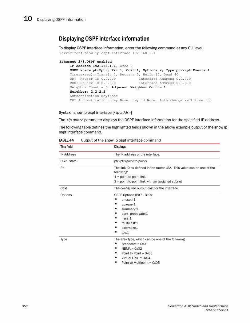
Displaying OSPF information10DRAFT: BROCADE CONFIDENTIAL
Displaying OSPF interface informationTo display OSPF interface information, enter the following command at any CLI level.
Syntax: show ip ospf interface [<ip-addr>]
The <ip-addr> parameter displays the OSPF interface information for the specified IP address.
The following table defines the highlighted fields shown in the above example output of the show ip ospf interface command.
TABLE 44 Output of the show ip ospf interface command
This field Displays
IP Address The IP address of the interface.
OSPF state ptr2ptr (point to point)
Pri The link ID as defined in the router-LSA. This value can be one of the following:1 = point-to-point link3 = point-to-point link with an assigned subnet
Cost The configured output cost for the interface.
Options OSPF Options (Bit7 - Bit0):• unused:1• opaque:1• summary:1• dont_propagate:1• nssa:1• multicast:1• externals:1• tos:1
Type The area type, which can be one of the following:• Broadcast = 0x01• NBMA = 0x02• Point to Point = 0x03• Virtual Link = 0x04• Point to Multipoint = 0x05
ServerIron# show ip ospf interface 192.168.1.1
Ethernet 2/1,OSPF enabled IP Address 192.168.1.1, Area 0 OSPF state ptr2ptr, Pri 1, Cost 1, Options 2, Type pt-2-pt Events 1 Timers(sec): Transit 1, Retrans 5, Hello 10, Dead 40 DR: Router ID 0.0.0.0 Interface Address 0.0.0.0 BDR: Router ID 0.0.0.0 Interface Address 0.0.0.0 Neighbor Count = 0, Adjacent Neighbor Count= 1 Neighbor: 2.2.2.2 Authentication-Key:None MD5 Authentication: Key None, Key-Id None, Auth-change-wait-time 300
358 ServerIron ADX Switch and Router Guide53-1001742-01

Displaying OSPF information 10DRAFT: BROCADE CONFIDENTIAL
Displaying OSPF route informationTo display OSPF route information, enter the following command at any CLI level.
Syntax: show ip ospf routes [<ip-addr>]
The <ip-addr> parameter specifies a destination IP address. If you use this parameter, only the route entries for that destination are shown.
This display shows the following information.
Events OSPF Interface Event:• Interface_Up = 0x00• Wait_Timer = 0x01• Backup_Seen = 0x02• Neighbor_Change = 0x03• Loop_Indication = 0x04• Unloop_Indication = 0x05• Interface_Down = 0x06• Interface_Passive = 0x07
Adjacent Neighbor Count The number of adjacent neighbor routers.
Neighbor: The neighbor router’s ID.
TABLE 45 CLI display of OSPF route information
This field... Displays...
Index The row number of the entry in the router’s OSPF route table.
Destination The IP address of the route's destination.
Mask The network mask for the route.
Path_Cost The cost of this route path. (A route can have multiple paths. Each path represents a different exit port for the Layer 3 Switch.)
Type2_Cost The type 2 cost of this path.
TABLE 44 Output of the show ip ospf interface command
This field Displays
ServerIron> show ip ospf routesIndex Destination Mask Path_Cost Type2_Cost Path_Type1 212.95.7.0 255.255.255.0 1 0 Intra Adv_Router Link_State Dest_Type State Tag Flags 173.35.1.220 212.95.7.251 Network Valid 00000000 7000 Paths Out_Port Next_Hop Type Arp_Index State 1 5/6 209.95.7.250 OSPF 8 84 00
Index Destination Mask Path_Cost Type2_Cost Path_Type2 11.3.63.0 255.255.255.0 11 0 Inter Adv_Router Link_State Dest_Type State Tag Flags 209.95.7.250 11.3.63.0 Network Valid 00000000 0000 Paths Out_Port Next_Hop Type Arp_Index State 1 5/6 209.95.7.250 OSPF 8 84 00
ServerIron ADX Switch and Router Guide 35953-1001742-01
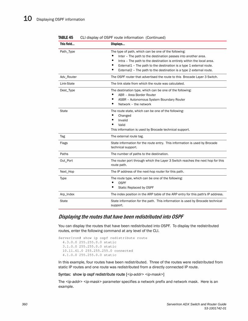
Displaying OSPF information10DRAFT: BROCADE CONFIDENTIAL
Displaying the routes that have been redistributed into OSPF
You can display the routes that have been redistributed into OSPF. To display the redistributed routes, enter the following command at any level of the CLI.
ServerIron# show ip ospf redistribute route 4.3.0.0 255.255.0.0 static 3.1.0.0 255.255.0.0 static 10.11.61.0 255.255.255.0 connected 4.1.0.0 255.255.0.0 static
In this example, four routes have been redistributed. Three of the routes were redistributed from static IP routes and one route was redistributed from a directly connected IP route.
Syntax: show ip ospf redistribute route [<ip-addr> <ip-mask>]
The <ip-addr> <ip-mask> parameter specifies a network prefix and network mask. Here is an example.
Path_Type The type of path, which can be one of the following:• Inter – The path to the destination passes into another area.• Intra – The path to the destination is entirely within the local area.• External1 – The path to the destination is a type 1 external route.• External2 – The path to the destination is a type 2 external route.
Adv_Router The OSPF router that advertised the route to this Brocade Layer 3 Switch.
Link-State The link state from which the route was calculated.
Dest_Type The destination type, which can be one of the following:• ABR – Area Border Router • ASBR – Autonomous System Boundary Router• Network – the network
State The route state, which can be one of the following:• Changed • Invalid • ValidThis information is used by Brocade technical support.
Tag The external route tag.
Flags State information for the route entry. This information is used by Brocade technical support.
Paths The number of paths to the destination.
Out_Port The router port through which the Layer 3 Switch reaches the next hop for this route path.
Next_Hop The IP address of the next-hop router for this path.
Type The route type, which can be one of the following:• OSPF• Static Replaced by OSPF
Arp_Index The index position in the ARP table of the ARP entry for this path's IP address.
State State information for the path. This information is used by Brocade technical support.
TABLE 45 CLI display of OSPF route information (Continued)
This field... Displays...
360 ServerIron ADX Switch and Router Guide53-1001742-01

Displaying OSPF information 10DRAFT: BROCADE CONFIDENTIAL
Displaying OSPF external link state informationTo display external link state information, enter the following command at any CLI level.
Syntax: show ip ospf database external-link-state [advertise <num>] | [extensive] | [link-state-id <ip-addr>] | [router-id <ip-addr>] | [sequence-number <num(Hex)>] | [status <num>]
The advertise <num> parameter displays the hexadecimal data in the specified LSA packet. The <num> parameter identifies the LSA packet by its position in the router’s External LSA table. To determine an LSA packet’s position in the table, enter the show ip ospf external-link-state command to display the table. Refer to “Displaying the data in an LSA” on page 363 for an example.
The extensive option displays the LSAs in decrypted format.
NOTEYou cannot use the extensive option in combination with other display options. The entire database is displayed.
The link-state-id <ip-addr> parameter displays the External LSAs for the LSA source specified by <IP-addr>.
The router-id <ip-addr> parameter shows the External LSAs for the specified OSPF router.
The sequence-number <num(Hex)> parameter displays the External LSA entries for the specified hexadecimal LSA sequence number.
The status <num> option shows status information.
This display shows the following information.
TABLE 46 CLI display of OSPF external link state information
This field... Displays...
Area ID The OSPF area the router is in.
Aging The age of the LSA, in seconds.
LS ID The ID of the link-state advertisement from which the Layer 3 Switch learned this route.
Router The router IP address.
ServerIron# show ip ospf redistribute route 3.1.0.0 255.255.0.0 3.1.0.0 255.255.0.0 static
ServerIron> show ip ospf database external-link-stateOspf ext link-state by router ID 130.130.130.241 are in the following:
Area ID Aging LS ID Router Seq(hex) Chksum Type0.0.0.0 279 130.132.75.48 130.130.130.241 80000004 00000ace EXTR0.0.0.0 278 130.132.88.112 130.130.130.241 80000004 0000f793 EXTR0.0.0.0 279 130.132.81.208 130.130.130.241 80000004 000081b0 EXTR0.0.0.0 284 130.132.46.224 130.130.130.241 80000004 000063e1 EXTR0.0.0.0 285 130.132.40.64 140.140.140.243 80000004 0000ebff EXTR0.0.0.0 286 130.132.33.160 150.150.150.245 80000004 0000751d EXTR0.0.0.0 296 130.131.241.16 150.150.150.245 80000004 00002e25 EXTR
ServerIron ADX Switch and Router Guide 36153-1001742-01

Displaying OSPF information10DRAFT: BROCADE CONFIDENTIAL
Displaying OSPF link state informationTo display link state information, enter the following command at any CLI level.
ServerIron> show ip ospf database link-state
Syntax: show ip ospf database link-state [advertise <num>] | [asbr] | [extensive] | [link-state-id <ip-addr>] | [network] | [nssa] | [opaque-area] | [router] | [router-id <ip-addr>] | [sequence-number <num(Hex)>] | [status <num>] | [summary]
The advertise <num> parameter displays the hexadecimal data in the specified LSA packet. The <num> parameter identifies the LSA packet by its position in the router’s External LSA table. To determine an LSA packet’s position in the table, enter the show ip ospf external-link-state command to display the table. Refer to “Displaying the data in an LSA” on page 363 for an example.
The asbr option shows ASBR information.
The extensive option displays the LSAs in decrypted format.
NOTEYou cannot use the extensive option in combination with other display options. The entire database is displayed.
The link-state-id <ip-addr> parameter displays the External LSAs for the LSA source specified by <IP-addr>.
The network option shows network information.
The nssa option shows network information.
The opaque-area option shows information for opaque areas.
The router-id <ip-addr> parameter shows the External LSAs for the specified OSPF router.
The sequence-number <num(Hex)> parameter displays the External LSA entries for the specified hexadecimal LSA sequence number.
The status <num> option shows status information.
The summary option shows summary information.
Seq(hex) The sequence number of the LSA. The OSPF neighbor that sent the LSA stamps it with a sequence number to enable the Layer 3 Switch and other OSPF routers to determine which LSA for a given route is the most recent.
Chksum A checksum for the LSA packet. The checksum is based on all the fields in the packet except the age field. The Layer 3 Switch uses the checksum to verify that the packet is not corrupted.
Type The route type, which is always EXTR (external).
TABLE 46 CLI display of OSPF external link state information (Continued)
This field... Displays...
362 ServerIron ADX Switch and Router Guide53-1001742-01

Displaying OSPF information 10DRAFT: BROCADE CONFIDENTIAL
Displaying the data in an LSAYou can use the CLI to display the data the Layer 3 Switch received in a specific External LSA packet or other type of LSA packet. For example, to display the LSA data in entry 3 in the External LSA table, enter the following command.
Syntax: show ip ospf database external-link-state [advertise <num>] | [link-state-id <ip-addr>] | [router-id <ip-addr>] | [sequence-number <num(Hex)>] | [status <num>]
To determine an external LSA's or other type of LSA’s index number, enter one of the following commands to display the appropriate LSA table:
• show ip ospf database link-state advertise <num> – This command displays the data in the packet for the specified LSA.
• show ip ospf database external-link-state advertise <num> – This command displays the data in the packet for the specified external LSA.
For example, to determine an external LSA's index number, enter the following command.
Displaying OSPF virtual neighbor informationTo display OSPF virtual neighbor information, enter the following command at any CLI level.
ServerIron> show ip ospf virtual-neighbor
Syntax: show ip ospf virtual-neighbor [<num>]
The <num> parameter displays the table beginning at the specified entry number.
Displaying OSPF virtual link informationTo display OSPF virtual link information for the router, use one of the following methods.
ServerIron> show ip ospf virtual-link
Syntax: show ip ospf virtual-link [<num>]
The <num> parameter displays the table beginning at the specified entry number.
Displaying OSPF ABR and ASBR informationTo display OSPF ABR and ASBR information, enter the following command at any CLI level.
ServerIron> show ip ospf border-routers
ServerIron> show ip ospf database external-link-state advertise 305 84 02 05 82 83 0d 60 82 82 82 f1 80 00 00 02 e4 0500 24 ff ff ff f0 80 00 00 0a 00 00 00 00 00 00 00 00
ServerIron> show ip ospf external-link-stateIndex Aging LS ID Router Seq(hex) Chksum1 1332 130.132.81.208 130.130.130.241 80000002 000085ae2 1325 130.132.116.192 130.130.130.241 80000002 0000a37d3 1330 130.132.88.112 130.130.130.241 80000002 0000fb914 1333 130.132.75.48 130.130.130.241 80000002 00000ecc5 1338 130.132.46.224 130.130.130.241 80000002 000067dfadditional entries omitted for brevity...
ServerIron ADX Switch and Router Guide 36353-1001742-01
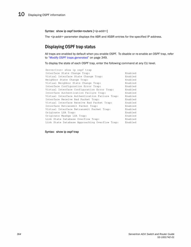
Displaying OSPF information10DRAFT: BROCADE CONFIDENTIAL
Syntax: show ip ospf border-routers [<ip-addr>]
The <ip-addr> parameter displays the ABR and ASBR entries for the specified IP address.
Displaying OSPF trap statusAll traps are enabled by default when you enable OSPF. To disable or re-enable an OSPF trap, refer to “Modify OSPF traps generated” on page 349.
To display the state of each OSPF trap, enter the following command at any CLI level.
Syntax: show ip ospf trap
ServerIron> show ip ospf trapInterface State Change Trap: EnabledVirtual Interface State Change Trap: EnabledNeighbor State Change Trap: EnabledVirtual Neighbor State Change Trap: EnabledInterface Configuration Error Trap: EnabledVirtual Interface Configuration Error Trap: EnabledInterface Authentication Failure Trap: EnabledVirtual Interface Authentication Failure Trap: EnabledInterface Receive Bad Packet Trap: EnabledVirtual Interface Receive Bad Packet Trap: EnabledInterface Retransmit Packet Trap: EnabledVirtual Interface Retransmit Packet Trap: EnabledOriginate LSA Trap: EnabledOriginate MaxAge LSA Trap: EnabledLink State Database Overflow Trap: EnabledLink State Database Approaching Overflow Trap: Enabled
364 ServerIron ADX Switch and Router Guide53-1001742-01

ServerIron ADX Switch and Router Guide53-1001742-01
DRAFT: BROCADE CONFIDENTIAL
Chapter
11
Configuring IPv6 AddressingIn this chapter•IPv6 Addressing Overview. . . . . . . . . . . . . . . . . . . . . . . . . . . . . . . . . . . . . . . 365
•Configuring IPv6 on Switch Code . . . . . . . . . . . . . . . . . . . . . . . . . . . . . . . . . 370
•IPv6 Management . . . . . . . . . . . . . . . . . . . . . . . . . . . . . . . . . . . . . . . . . . . . . 378
•Configuring a Static IPv6 Route . . . . . . . . . . . . . . . . . . . . . . . . . . . . . . . . . . 383
•ECMP Load Sharing for IPv6 . . . . . . . . . . . . . . . . . . . . . . . . . . . . . . . . . . . . . 385
•Configuring IPv6 ICMP Features. . . . . . . . . . . . . . . . . . . . . . . . . . . . . . . . . . 386
•Configuring IPv6 Neighbor Discovery . . . . . . . . . . . . . . . . . . . . . . . . . . . . . . 388
•Configuring Static Neighbor Entries . . . . . . . . . . . . . . . . . . . . . . . . . . . . . . . 394
•Limiting the Number of Hops an IPv6 Packet Can Traverse . . . . . . . . . . . . 395
•Clearing IPv6 Information . . . . . . . . . . . . . . . . . . . . . . . . . . . . . . . . . . . . . . . 395
•Displaying IPv6 Information . . . . . . . . . . . . . . . . . . . . . . . . . . . . . . . . . . . . . 397
•Debugging IPv6 Configuration Issues . . . . . . . . . . . . . . . . . . . . . . . . . . . . . 413
This chapter explains IPv6 addressing and features and how to configure them on a ServerIron ADX.
IPv6 Addressing OverviewIPv4 is unable to satisfy potential increases in the number of users, geographical needs, and emerging applications because of its 32-bit addressing format. To address this limitation, IPv6 introduces a new 128-bit addressing format.
An IPv6 address is composed of 8 fields of 16-bit hexadecimal values separated by colons (:). Figure 75 shows the IPv6 address format.
FIGURE 75 IPv6 Address Format
As shown in Figure 75, HHHH is a 16-bit hexadecimal value, while H is a 4-bit hexadecimal value. The following is an example of an IPv6 address:
2001:0000:0000:0200:002D:D0FF:FE48:4672
Network Prefix Interface ID
128 BitsHHHH = Hex Value 0000 - FFFF
HHHH HHHH HHHH HHHH HHHH HHHH HHHH HHHH
365

IPv6 Addressing Overview11DRAFT: BROCADE CONFIDENTIAL
Note that this IPv6 address includes hexadecimal fields of zeros. To make the address less cumbersome, you can do the following:
• Omit the leading zeros; for example, 2001:0:0:200:2D:D0FF:FE48:4672.
• Compress the successive groups of zeros at the beginning, middle, or end of an IPv6 address to two colons (::) once per address; for example, 2001::200:2D:D0FF:FE48:4672.
When specifying an IPv6 address in a command syntax, keep the following in mind:
You can use the two colons (::) only once in the address to represent successive hexadecimal fields of zeros
The hexadecimal letters in IPv6 addresses are not case-sensitive
As shown in Figure 75, the IPv6 network prefix is composed of the left-most bits of the address. As with an IPv4 address, you can specify the IPv6 prefix using the <prefix>/<prefix-length> format, where the following applies:
• The <prefix> parameter is specified as 16-bit hexadecimal values separated by a colon.
• The <prefix-length> parameter is specified as a decimal value that indicates the left-most bits of the IPv6 address.
The following is an example of an IPv6 prefix:
2001:FF08:49EA:D088::/64
IPv6 Address TypesYou can assign multiple IPv6 addresses to an interface. Table 47 presents the three major types of IPv6 addresses that you can assign to an interface.
A major difference between IPv4 and IPv6 addresses is that IPv6 addresses have scope, which describes the topology in which the address may be used as a unique identifier for an interface or set of interfaces.
Unicast and multicast addresses scoping is discussed below:
• Unicast addresses have two types of scope: global scope and local scope. The local scope in turn has two types: site-local addresses and link-local addresses. Table 47 describes global, site-local, and link-local addresses and the topologies in which they are used.
366 ServerIron ADX Switch and Router Guide53-1001742-01

IPv6 Addressing Overview 11DRAFT: BROCADE CONFIDENTIAL
• Multicast addresses support a scope field, which Table 47 describes..
A switch automatically configures a link-local unicast address for an interface by using the prefix of FE80::/10 (1111 1110 10) and a 64-bit interface ID. The 128-bit IPv6 address is then subjected to duplicate address detection to ensure that the address is unique on the link. If desired, you can override this automatically configured address by explicitly configuring an address.
TABLE 47 IPv6 address types
Address Type
Description Address Structure
Unicast An address for a single interface. A packet sent to a unicast address is delivered to the interface identified by the address.
Depends on the type of the unicast address:• Aggregatable global address—An address equivalent to a
global or public IPv4 address. The address structure is as follows: a fixed prefix of 2000::/3 (001), a 45-bit global routing prefix, a 16-bit subnet ID, and a 64-bit interface ID.
• Site-local address—An address used within a site or intranet. (This address is similar to a private IPv4 address.) A site consists of multiple network links. The address structure is as follows: a fixed prefix of FEC0::/10 (1111 1110 11), a 16-bit subnet ID, and a 64-bit interface ID.
• Link-local address—An address used between directly connected nodes on a single network link. The address structure is as follows: a fixed prefix of FE80::/10 (1111 1110 10) and a 64-bit interface ID.
• IPv4-compatible address—An address used in IPv6 transition mechanisms that tunnel IPv6 packets dynamically over IPv4 infrastructures. The address embeds an IPv4 address in the low-order 32 bits and the high-order 96 bits are zeros. The address structure is as follows: 0:0:0:0:0:0:A.B.C.D.
• Loopback address—An address (0:0:0:0:0:0:0:1 or ::1) that a switch can use to send an IPv6 packet to itself. You cannot assign a loopback address to a physical interface.
• Unspecified address—An address (0:0:0:0:0:0:0:0 or ::) that a node can use until you configure an IPv6 address for it.
Multicast An address for a set of interfaces belonging to different nodes. Sending a packet to a multicast address results in the delivery of the packet to all interfaces in the set.
A multicast address has a fixed prefix of FF00::/8 (1111 1111). The next 4 bits define the address as a permanent or temporary address. The next 4 bits define the scope of the address (node, link, site, organization, global).
Anycast An address for a set of interfaces belonging to different nodes. Sending a packet to an anycast address results in the delivery of the packet to the closest interface identified by the address.
An anycast address looks similar to a unicast address, because it is allocated from the unicast address space. If you assign a unicast address to multiple interfaces, it is an anycast address. An interface assigned an anycast address must be configured to recognize the address as an anycast address.An anycast address can be assigned to a switch only.An anycast address must not be used as the source address of an IPv6 packet.
ServerIron ADX Switch and Router Guide 36753-1001742-01
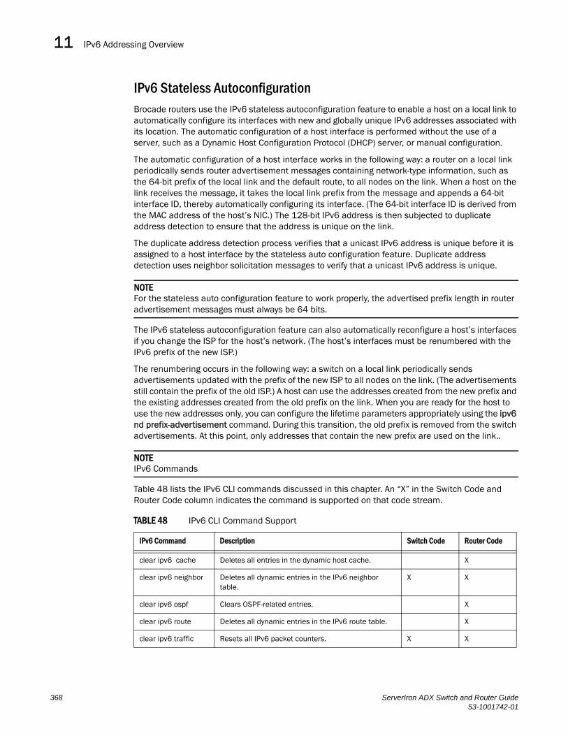
IPv6 Addressing Overview11DRAFT: BROCADE CONFIDENTIAL
IPv6 Stateless AutoconfigurationBrocade routers use the IPv6 stateless autoconfiguration feature to enable a host on a local link to automatically configure its interfaces with new and globally unique IPv6 addresses associated with its location. The automatic configuration of a host interface is performed without the use of a server, such as a Dynamic Host Configuration Protocol (DHCP) server, or manual configuration.
The automatic configuration of a host interface works in the following way: a router on a local link periodically sends router advertisement messages containing network-type information, such as the 64-bit prefix of the local link and the default route, to all nodes on the link. When a host on the link receives the message, it takes the local link prefix from the message and appends a 64-bit interface ID, thereby automatically configuring its interface. (The 64-bit interface ID is derived from the MAC address of the host’s NIC.) The 128-bit IPv6 address is then subjected to duplicate address detection to ensure that the address is unique on the link.
The duplicate address detection process verifies that a unicast IPv6 address is unique before it is assigned to a host interface by the stateless auto configuration feature. Duplicate address detection uses neighbor solicitation messages to verify that a unicast IPv6 address is unique.
NOTEFor the stateless auto configuration feature to work properly, the advertised prefix length in router advertisement messages must always be 64 bits.
The IPv6 stateless autoconfiguration feature can also automatically reconfigure a host’s interfaces if you change the ISP for the host’s network. (The host’s interfaces must be renumbered with the IPv6 prefix of the new ISP.)
The renumbering occurs in the following way: a switch on a local link periodically sends advertisements updated with the prefix of the new ISP to all nodes on the link. (The advertisements still contain the prefix of the old ISP.) A host can use the addresses created from the new prefix and the existing addresses created from the old prefix on the link. When you are ready for the host to use the new addresses only, you can configure the lifetime parameters appropriately using the ipv6 nd prefix-advertisement command. During this transition, the old prefix is removed from the switch advertisements. At this point, only addresses that contain the new prefix are used on the link..
NOTEIPv6 Commands
Table 48 lists the IPv6 CLI commands discussed in this chapter. An “X” in the Switch Code and Router Code column indicates the command is supported on that code stream.
TABLE 48 IPv6 CLI Command Support
IPv6 Command Description Switch Code Router Code
clear ipv6 cache Deletes all entries in the dynamic host cache. X
clear ipv6 neighbor Deletes all dynamic entries in the IPv6 neighbor table.
X X
clear ipv6 ospf Clears OSPF-related entries. X
clear ipv6 route Deletes all dynamic entries in the IPv6 route table. X
clear ipv6 traffic Resets all IPv6 packet counters. X X
368 ServerIron ADX Switch and Router Guide53-1001742-01
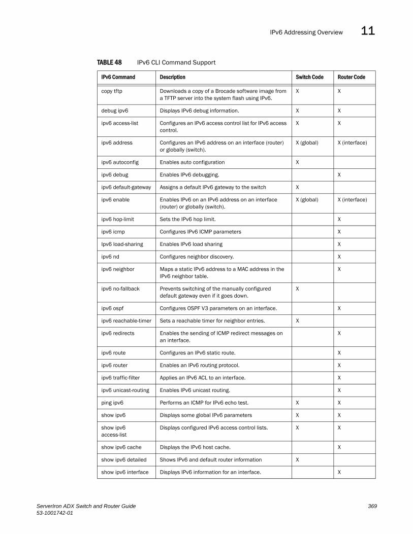
IPv6 Addressing Overview 11DRAFT: BROCADE CONFIDENTIAL
copy tftp Downloads a copy of a Brocade software image from a TFTP server into the system flash using IPv6.
X X
debug ipv6 Displays IPv6 debug information. X X
ipv6 access-list Configures an IPv6 access control list for IPv6 access control.
X X
ipv6 address Configures an IPv6 address on an interface (router) or globally (switch).
X (global) X (interface)
ipv6 autoconfig Enables auto configuration X
ipv6 debug Enables IPv6 debugging. X
ipv6 default-gateway Assigns a default IPv6 gateway to the switch X
ipv6 enable Enables IPv6 on an IPv6 address on an interface (router) or globally (switch).
X (global) X (interface)
ipv6 hop-limit Sets the IPv6 hop limit. X
ipv6 icmp Configures IPv6 ICMP parameters X
Ipv6 load-sharing Enables IPv6 load sharing X
ipv6 nd Configures neighbor discovery. X
ipv6 neighbor Maps a static IPv6 address to a MAC address in the IPv6 neighbor table.
X
ipv6 no-fallback Prevents switching of the manually configured default gateway even if it goes down.
X
ipv6 ospf Configures OSPF V3 parameters on an interface. X
ipv6 reachable-timer Sets a reachable timer for neighbor entries. X
ipv6 redirects Enables the sending of ICMP redirect messages on an interface.
X
ipv6 route Configures an IPv6 static route. X
ipv6 router Enables an IPv6 routing protocol. X
ipv6 traffic-filter Applies an IPv6 ACL to an interface. X
ipv6 unicast-routing Enables IPv6 unicast routing. X
ping ipv6 Performs an ICMP for IPv6 echo test. X X
show ipv6 Displays some global IPv6 parameters X X
show ipv6 access-list
Displays configured IPv6 access control lists. X X
show ipv6 cache Displays the IPv6 host cache. X
show ipv6 detailed Shows IPv6 and default router information X
show ipv6 interface Displays IPv6 information for an interface. X
TABLE 48 IPv6 CLI Command Support
IPv6 Command Description Switch Code Router Code
ServerIron ADX Switch and Router Guide 36953-1001742-01

Configuring IPv6 on Switch Code11DRAFT: BROCADE CONFIDENTIAL
In addition to these commands, ServerIron ADX supports the following IPv6 features:
• Access control list (See the Configuring IPv6 Access Control Lists chapter of the ServerIron TrafficWorks Security Guide
• VRRP-E (See “Configuring VRRP and VRRP-E” on page 173 .)
• OSPF v3 (See “Configuring IPv6 Dynamic Routing” on page 415.)
Configuring IPv6 on Switch CodeThe sections below discuss the IPv6 features available on a ServerIron ADX running switch code.
Enabling IPv6By default, IPv6 is enabled on ServerIron ADXs running switch code. It can be disabled globally by entering the following command:
ServerIron(config)#no ipv6 enable
Syntax: [no] ipv6 enable
Use the ipv6 enable command to re-enable it.
NOTEYou cannot enable or disable IPv6 on an interface; it is enabled or disabled globally in switch code.
Configuring an IPv6 Address on a SwitchIn a Layer 3 (router) configuration, each port can be configured separately with an IPv6 address. This is accomplished using the steps described in “Enabling Basic IPv6 Connectivity on Router Code” on page 375.
show ipv6 neighbor Displays the IPv6 neighbor table. X X
show ipv6 ospf Displays information about OSPF V3. X
show ipv6 route Displays IPv6 routes. X
show ipv6 router Displays IPv6 local routers. X
show ipv6 tcp Displays information about IPv6 TCP sessions. X X
show ipv6 traffic Displays IPv6 packet counters. X X
telnet Enables a Telnet connection from the Brocade device to a remote IPv6 host using the console.
X X
TABLE 48 IPv6 CLI Command Support
IPv6 Command Description Switch Code Router Code
370 ServerIron ADX Switch and Router Guide53-1001742-01

Configuring IPv6 on Switch Code 11DRAFT: BROCADE CONFIDENTIAL
In a Layer 2 (switch) configuration, individual ports cannot be configured with an IP address (IPv4 or IPv6). In this situation, the switch will have one management IP address. Configuration of the system-wide IPv6 address is exactly like configuration of an IPv6 address in router mode, except that the IPv6 configuration is at the Global configuration level instead of at the interface configuration level.
The process for defining the system-wide interface for IPv6 is described in the following sections:
• “Configuring a Global or Site-Local IPv6 Address” on page 372
• “Configuring a Link-Local IPv6 Address” on page 372
NOTEWhen configuring an IPv6 host address on a Layer 2 switch that has multiple VLANs, make sure the configuration includes a designated management VLAN that identifies the VLAN to which the global IP address belongs.
Configuring IPv6 auto configurationTo configure a ServerIron ADX for IPv6 auto configuration, use the following command.
ServerIron(config)# ipv6 autoconfig
Syntax: ipv6 autoconfig
NOTEIPv6 auto configuration is enabled by default in the swich code.
Configuring Reachable Time for Remote IPv6 Nodes (global)You can configure the duration (in seconds) that a ServerIron running switch code considers a remote IPv6 node reachable. By default, a router interface uses the value of 30 seconds. This timer can be set globally for a ServerIron ADX running switch code and per-interface for a ServerIron ADX running router code as described in “Configuring Reachable Time for Remote IPv6 Nodes” on page 394.
The router advertisement messages sent by a router interface include the amount of time specified by the ipv6 nd reachable-time command so that nodes on a link use the same reachable time duration. By default, the messages include a default value of 0.
Brocade does not recommend configuring a short reachable time duration, because a short duration causes the IPv6 network devices to process the information at a greater frequency.
For example, to globally configure the reachable time of 40 seconds, enter the following commands:
ServerIron(config)# ipv6 reachable-time 40
Syntax: [no] ipv6 reachable-time <seconds>
For the <seconds> parameter, specify a number from 0 – 3600 seconds. By default, the reachable time for any host varies between 15 and 45 seconds. This is a value calculated when IPv6 is enabled for the interface. The reachable time for router neighbor entries is 600 seconds. This is because we want to keep this neighbor reachable for longer than other hosts. Also, once you configure the reachable timer, the reachable timer for router entries is set to the higher of the newly configured values plus 600 seconds.
ServerIron ADX Switch and Router Guide 37153-1001742-01

Configuring IPv6 on Switch Code11DRAFT: BROCADE CONFIDENTIAL
To restore the default time, use the no form of this command.
NOTEThe actual reachable time will be from .5 to 1.5 times the configured or default value.
Configuring a Global or Site-Local IPv6 Address To configure a global or site-local IPv6 address with a manually configured interface ID, as a switch’s system-wide address, enter a command such as the following at the Global Config level:
ServerIron(config)#ipv6 address 2001:200:12D:1300:240:D0FF:FE48:4000:1/64
Syntax: ipv6 address <ipv6-prefix>/<prefix-length>
You must specify the <ipv6-prefix> parameter in hexadecimal using 16-bit values between colons as documented in RFC 2373.
You must specify the <prefix-length> parameter in decimal value. A slash mark (/) must follow the <ipv6-prefix> parameter and precede the <prefix-length> parameter.
Configuring a Link-Local IPv6 AddressTo manually configure a global or site-local IPv6 address as switch address, enter the following command at the global configuration level:
ServerIron(config)# ipv6 enable
This command enables IPv6 on the switch and specifies that the interface is assigned an automatically computed link-local address.
Syntax: [no] ipv6 enable
To override a link-local address that is automatically computed for the global interface with a manually configured address, enter a command such as the following:
ServerIron(config)#ipv6 address FE80::240:D0FF:FE48:4672 link-local
This command explicitly configures the link-local address for the global interface.
Syntax: ipv6 address <ipv6-address> link-local
You must specify the <ipv6-address> parameter in hexadecimal using 16-bit values between colons as documented in RFC 2373.
The link-local keyword indicates that the router interface should use the manually configured link-local address instead of the automatically computed link-local address.
Configuring a Default Gateway for IPv6 on Switch CodeThe ServerIron ADX running switch code learns about its upstream router(s) through their respective IPv6 router advertisements. ServerIron ADX then auto-configures its default gateway after receiving these advertisements. By default, it configures the link-local address of the first router advertisement that it has received as its default gateway.
If however one wishes to be more deterministic and wants to define in advance a default gateway for the ServerIron ADX, then the following command can be used:
372 ServerIron ADX Switch and Router Guide53-1001742-01
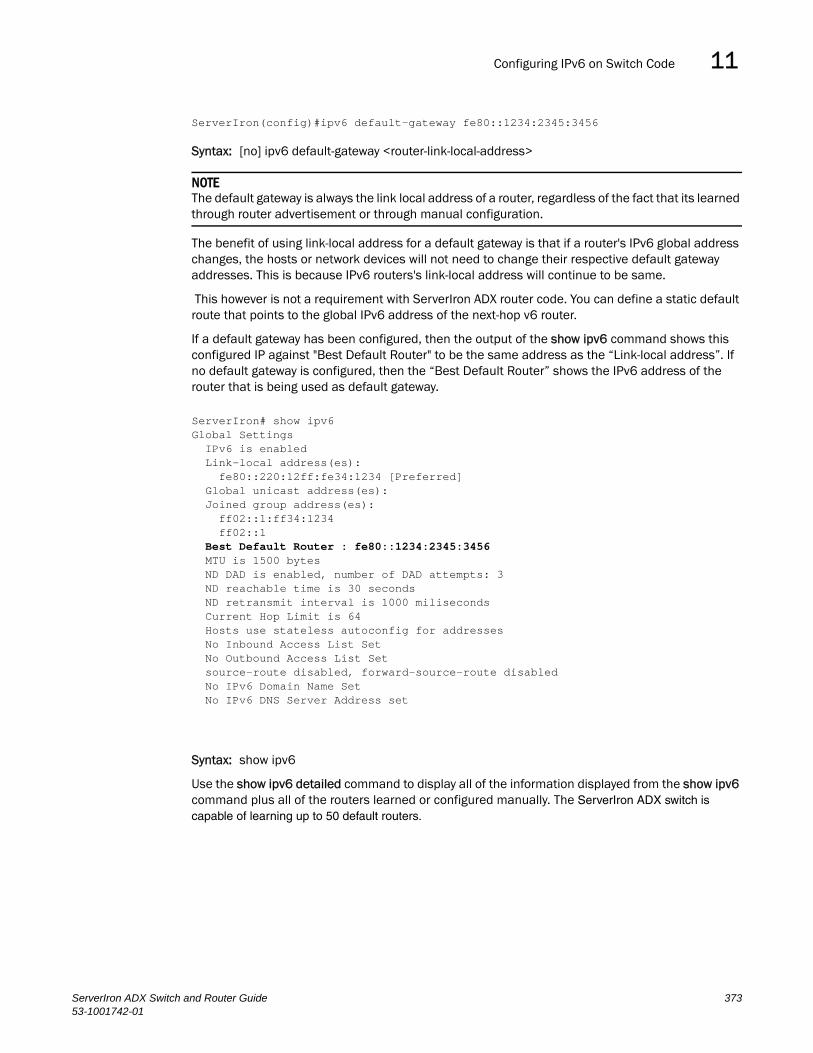
Configuring IPv6 on Switch Code 11DRAFT: BROCADE CONFIDENTIAL
ServerIron(config)#ipv6 default-gateway fe80::1234:2345:3456
Syntax: [no] ipv6 default-gateway <router-link-local-address>
NOTEThe default gateway is always the link local address of a router, regardless of the fact that its learned through router advertisement or through manual configuration.
The benefit of using link-local address for a default gateway is that if a router's IPv6 global address changes, the hosts or network devices will not need to change their respective default gateway addresses. This is because IPv6 routers's link-local address will continue to be same.
This however is not a requirement with ServerIron ADX router code. You can define a static default route that points to the global IPv6 address of the next-hop v6 router.
If a default gateway has been configured, then the output of the show ipv6 command shows this configured IP against "Best Default Router" to be the same address as the “Link-local address”. If no default gateway is configured, then the “Best Default Router” shows the IPv6 address of the router that is being used as default gateway.
Syntax: show ipv6
Use the show ipv6 detailed command to display all of the information displayed from the show ipv6 command plus all of the routers learned or configured manually. The ServerIron ADX switch is capable of learning up to 50 default routers.
ServerIron# show ipv6Global Settings IPv6 is enabled Link-local address(es): fe80::220:12ff:fe34:1234 [Preferred] Global unicast address(es): Joined group address(es): ff02::1:ff34:1234 ff02::1 Best Default Router : fe80::1234:2345:3456 MTU is 1500 bytes ND DAD is enabled, number of DAD attempts: 3 ND reachable time is 30 seconds ND retransmit interval is 1000 miliseconds Current Hop Limit is 64 Hosts use stateless autoconfig for addresses No Inbound Access List Set No Outbound Access List Set source-route disabled, forward-source-route disabled No IPv6 Domain Name Set No IPv6 DNS Server Address set
ServerIron ADX Switch and Router Guide 37353-1001742-01
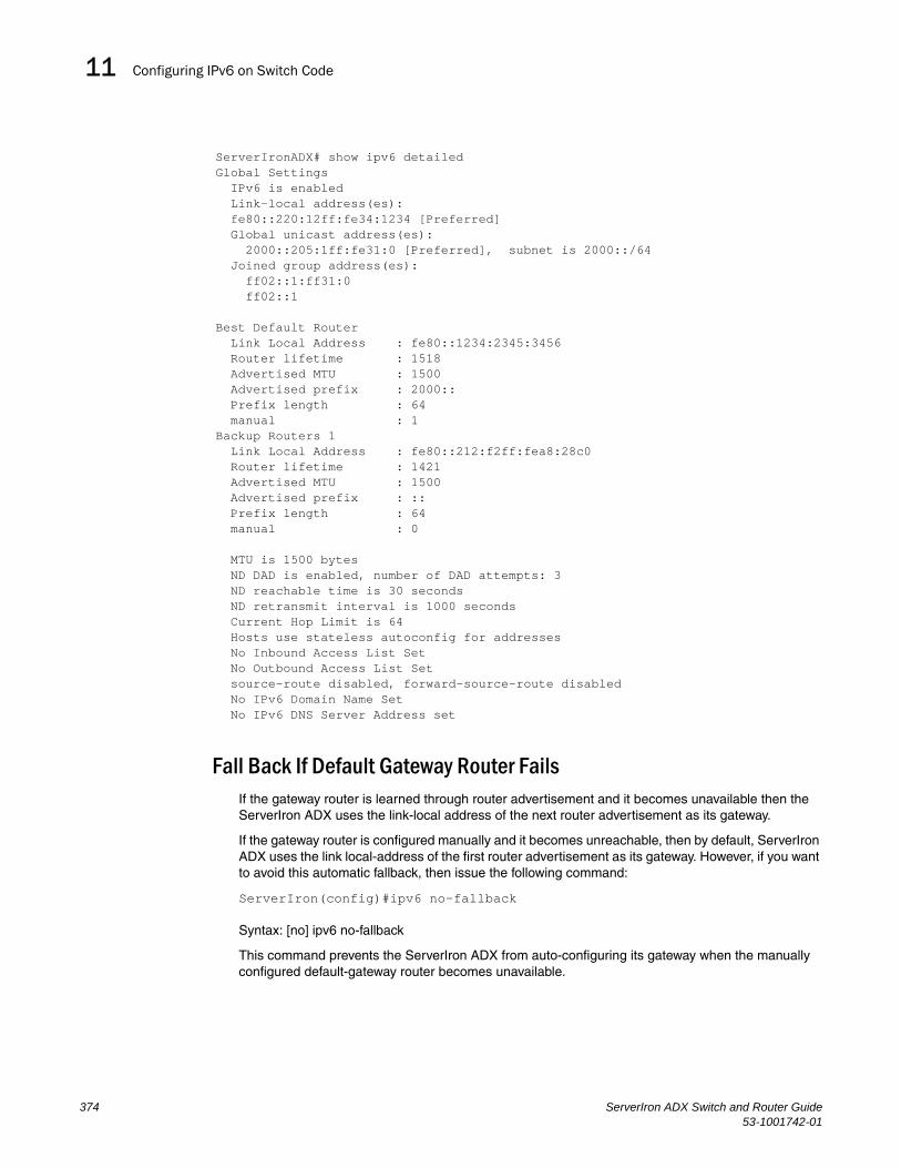
Configuring IPv6 on Switch Code11DRAFT: BROCADE CONFIDENTIAL
Fall Back If Default Gateway Router FailsIf the gateway router is learned through router advertisement and it becomes unavailable then the ServerIron ADX uses the link-local address of the next router advertisement as its gateway.
If the gateway router is configured manually and it becomes unreachable, then by default, ServerIron ADX uses the link local-address of the first router advertisement as its gateway. However, if you want to avoid this automatic fallback, then issue the following command:
ServerIron(config)#ipv6 no-fallback
Syntax: [no] ipv6 no-fallback
This command prevents the ServerIron ADX from auto-configuring its gateway when the manually configured default-gateway router becomes unavailable.
ServerIronADX# show ipv6 detailed Global Settings IPv6 is enabled Link-local address(es): fe80::220:12ff:fe34:1234 [Preferred] Global unicast address(es): 2000::205:1ff:fe31:0 [Preferred], subnet is 2000::/64 Joined group address(es): ff02::1:ff31:0 ff02::1
Best Default Router Link Local Address : fe80::1234:2345:3456 Router lifetime : 1518 Advertised MTU : 1500 Advertised prefix : 2000:: Prefix length : 64 manual : 1Backup Routers 1 Link Local Address : fe80::212:f2ff:fea8:28c0 Router lifetime : 1421 Advertised MTU : 1500 Advertised prefix : :: Prefix length : 64 manual : 0
MTU is 1500 bytes ND DAD is enabled, number of DAD attempts: 3 ND reachable time is 30 seconds ND retransmit interval is 1000 seconds Current Hop Limit is 64 Hosts use stateless autoconfig for addresses No Inbound Access List Set No Outbound Access List Set source-route disabled, forward-source-route disabled No IPv6 Domain Name Set No IPv6 DNS Server Address set
374 ServerIron ADX Switch and Router Guide53-1001742-01

Enabling Basic IPv6 Connectivity on Router Code 11DRAFT: BROCADE CONFIDENTIAL
Enabling Basic IPv6 Connectivity on Router CodeYou can enable basic IPv6 connectivity on a ServerIron running router code globally and on individual interfaces.
• Enable IPv6 routing globally.
• Configure an IPv6 address or explicitly enable IPv6 on each router interface over which you plan to forward IPv6 traffic.
• Configure IPv4 and IPv6 protocol stacks. (This step is mandatory only if you want a router interface to send and receive both IPv4 and IPv6 traffic.)
All other configuration tasks in this chapter are optional:
Enabling IPv6 Routing GloballyBy default, IPv6 routing is enabled. If you wish to disable IPv6 routing, then issue the following command:
ServerIron(config)# no ipv6 unicast-routing
Syntax: [no] ipv6 unicast-routing
Enabling IPv6 on Each Router InterfaceBy default IPv6 is not enabled on interfaces of ServerIron ADXs running router code. To forward IPv6 traffic on a router interface, you can do one of the following:
• Assign an IPv6 address to the router interface. By default, an IPv6 address is not configured on a router interface. (See “Assigning an IPv6 Address to an Interface” on page 375.)
• If an IPv6 address has not been configured on a router interface, you must enable IPv6 explicity on that interface. (See “Enabling IPv6 on Interfaces without an IPv6 Address” on page 375.)
Enabling IPv6 on Interfaces without an IPv6 Address
If an interface does not have an IPv6 address, you can enable IPv6 on that interface by entering the following command:
ServerIron(config)# ipv6 enable
Syntax: [no] ipv6 enable
Assigning an IPv6 Address to an Interface
When you configure a global or site-local IPv6 address for an interface, IPv6 is also enabled on the interface. Further, when you configure a global or site-local IPv6 address, you must decide on one of the following in the low-order 64 bits:
• A manually configured interface ID.
• An automatically computed EUI-64 interface ID.
ServerIron ADX Switch and Router Guide 37553-1001742-01

Enabling Basic IPv6 Connectivity on Router Code11DRAFT: BROCADE CONFIDENTIAL
If you prefer to assign a link-local IPv6 address to the interface, you must explicitly enable IPv6 on the interface, which causes a link-local address to be automatically computed for the interface. If preferred, you can override the automatically configured link-local address with an address that you manually configure.
This section provides the following information:
• Configuring a global or site-local address with a manually configured or automatically computed interface ID for an interface.
• Automatically or manually configuring a link-local address for an interface.
• Configuring IPv6 anycast addresses
Configuring a Global or Site-Local IPv6 Address on an Interface
Configuring a global or site-local IPv6 address on an interface does the following:
• Automatically configures an interface ID (a link-local address), if specified.
• Enables IPv6 on that interface.
Additionally, the configured interface automatically joins the following required multicast groups for that link:
• Solicited-node multicast group FF02:0:0:0:0:1:FF00::/104 for each unicast address assigned to the interface.
• Solicited-node for subnet anycast address for each unicast assigned address
• Solicited-node for anycast address FF02:0:0:0:0:1:FF00::0000
• All-nodes link-local multicast group FF02::1
• All-routers link-local multicast group FF02::2
The neighbor discovery feature sends messages to these multicast groups. For more information, see “Configuring IPv6 Neighbor Discovery” on page 388.
Configuring a Global or Site-Local IPv6 Address with a Manually Configured Interface IDTo configure a global or site-local IPv6 address, including a manually configured interface ID, for an interface, enter commands such as the following:
ServerIron(config)#interface ethernet 3/1ServerIron(config-if-e1000-3/1)# ipv6 address 2001:200:12D:1300:240:D0FF:FE48:4672/64These commands configure the global prefix 2001:200:12d:1300::/64 and the interface ID ::240:D0FF:FE48:4672, and enable IPv6 on Ethernet interface 3/1.
Syntax: ipv6 address <ipv6-prefix>/<prefix-length>
You must specify the <ipv6-prefix> parameter in hexadecimal using 16-bit values between colons as documented in RFC 2373.
You must specify the <prefix-length> parameter as a decimal value. A slash mark (/) must follow the <ipv6-prefix> parameter and precede the <prefix-length> parameter.
Configuring a Global IPv6 Address with an Automatically Computed EUI-64 Interface IDTo configure a global IPv6 address with an automatically computed EUI-64 interface ID in the low-order 64-bits, enter commands such as the following:
376 ServerIron ADX Switch and Router Guide53-1001742-01
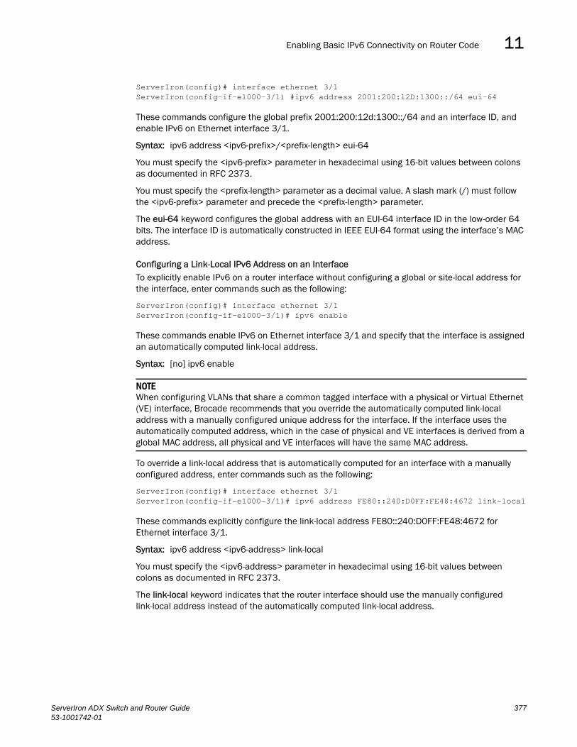
Enabling Basic IPv6 Connectivity on Router Code 11DRAFT: BROCADE CONFIDENTIAL
ServerIron(config)# interface ethernet 3/1ServerIron(config-if-e1000-3/1) #ipv6 address 2001:200:12D:1300::/64 eui-64
These commands configure the global prefix 2001:200:12d:1300::/64 and an interface ID, and enable IPv6 on Ethernet interface 3/1.
Syntax: ipv6 address <ipv6-prefix>/<prefix-length> eui-64
You must specify the <ipv6-prefix> parameter in hexadecimal using 16-bit values between colons as documented in RFC 2373.
You must specify the <prefix-length> parameter as a decimal value. A slash mark (/) must follow the <ipv6-prefix> parameter and precede the <prefix-length> parameter.
The eui-64 keyword configures the global address with an EUI-64 interface ID in the low-order 64 bits. The interface ID is automatically constructed in IEEE EUI-64 format using the interface’s MAC address.
Configuring a Link-Local IPv6 Address on an InterfaceTo explicitly enable IPv6 on a router interface without configuring a global or site-local address for the interface, enter commands such as the following:
ServerIron(config)# interface ethernet 3/1ServerIron(config-if-e1000-3/1)# ipv6 enable
These commands enable IPv6 on Ethernet interface 3/1 and specify that the interface is assigned an automatically computed link-local address.
Syntax: [no] ipv6 enable
NOTEWhen configuring VLANs that share a common tagged interface with a physical or Virtual Ethernet (VE) interface, Brocade recommends that you override the automatically computed link-local address with a manually configured unique address for the interface. If the interface uses the automatically computed address, which in the case of physical and VE interfaces is derived from a global MAC address, all physical and VE interfaces will have the same MAC address.
To override a link-local address that is automatically computed for an interface with a manually configured address, enter commands such as the following:
ServerIron(config)# interface ethernet 3/1ServerIron(config-if-e1000-3/1)# ipv6 address FE80::240:D0FF:FE48:4672 link-local
These commands explicitly configure the link-local address FE80::240:D0FF:FE48:4672 for Ethernet interface 3/1.
Syntax: ipv6 address <ipv6-address> link-local
You must specify the <ipv6-address> parameter in hexadecimal using 16-bit values between colons as documented in RFC 2373.
The link-local keyword indicates that the router interface should use the manually configured link-local address instead of the automatically computed link-local address.
ServerIron ADX Switch and Router Guide 37753-1001742-01

IPv6 Management11DRAFT: BROCADE CONFIDENTIAL
Configuring an IPv6 Anycast Address on an InterfaceIn IPv6, an anycast address is an address for a set of interfaces belonging to different nodes. Sending a packet to an anycast address results in the delivery of the packet to the closest interface configured with the anycast address.
An anycast address looks similar to a unicast address, because it is allocated from the unicast address space. If you assign an IPv6 unicast address to multiple interfaces, it is an anycast address. On the Brocade device, you configure an interface assigned an anycast address to recognize the address as an anycast address.
For example, the following commands configure an anycast address on interface 2/1:
ServerIron(config)#int e 2/1ServerIron(config-if-e1000-2/1)#ipv6 address 2002::/64 anycast
Syntax: ipv6 address <ipv6-prefix>/<prefix-length> [anycast]
IPv6 anycast addresses are described in detail in RFC 1884. See RFC 2461 for a description of how the IPv6 Neighbor Discovery mechanism handles anycast addresses.
IPv6 Management This section describes the following IPv6 management features:
• “IPv6 Access Control Lists”
• “Secure Shell, SCP, and IPv6”
• “IPv6 Telnet”
• “IPv6 Web Management using HTTP and HTTPS”
• “Using the IPv6 copy Command”
• “IPv6 Ping”
• “Disabling Router Advertisement and Solicitation Messages”
• “Debugging IPv6 Configuration Issues”
The following IPv6 host feature is also supported:
• “Configuring a Link-Local IPv6 Address”
IPv6 Access Control ListsYou can configure an IPv6 ACL to filter traffic to or from an IPv6 host. To do so, see the “Configuring IPv6 Access Control Lists (ACLs)” of the ServerIron TrafficWorks Security Guide.
Secure Shell, SCP, and IPv6Secure Shell (SSH) is a mechanism that allows secure remote access to management functions on the Brocade device. SSH provides a function similar to Telnet. You can log in to and configure the Brocade device using a publicly or commercially available SSH client program, just as you can with Telnet. However, unlike Telnet, which provides no security, SSH provides a secure, encrypted connection to the Brocade device.
378 ServerIron ADX Switch and Router Guide53-1001742-01

IPv6 Management 11DRAFT: BROCADE CONFIDENTIAL
To open an SSH session between an IPv6 host running an SSH client program and the Brocade device, open the SSH client program and specify the IPv6 address of the device. For more information about configuring SSH on the Brocade device, see the “Configuring SSH” and “Disabling and “Renabling Secure Copy” sections of the “ServerIron System Management” chapter in the ServerIron TrafficWorks Administration Guide.
IPv6 Telnet
Telnet sessions can be established between a device to a remote IPv6 host, and from a remote IPv6 host to the device using IPv6 addresses.
The telnet command establishes a Telnet connection from a Brocade device to a remote IPv6 host using the console. Up to five read-access Telnet sessions are supported on the router at one time. Write-access through Telnet is limited to one session, and only one outgoing Telnet session is supported on the router at one time. To see the number of open Telnet sessions at any time, enter the show telnet command.
Example
To establish a Telnet connection to a remote host with the IPv6 address of 3001:2837:3de2:c37::6, enter the following command:
ServerIron#telnet 3001:2837:3de2:c37::6
Syntax: telnet <ipv6-address> [<port-number> | outgoing-interface ethernet <port> | ve <number>]
The <ipv6-address> parameter specifies the address of a remote host. You must specify this address in hexadecimal using 16-bit values between colons as documented in RFC 2373.
The <port-number> parameter specifies the port number on which the Brocade device establishes the Telnet connection. You can specify a value between 1 - 65535. If you do not specify a port number, the Brocade device establishes the Telnet connection on port 23.
If the IPv6 address you specify is a link-local address, you must specify the outgoing-interface ethernet <port> | ve <number> parameter. This parameter identifies the interface that must be used to reach the remote host. If you specify an Ethernet interface, you must also specify the port number associated with the interface. If you specify a VE interface, also specify the VE number.
Establishing a Telnet Session From an IPv6 Host
To establish a Telnet session from an IPv6 host to the Brocade device, open your Telnet application and specify the IPv6 address of the Layer 3 Switch.
IPv6 Web Management using HTTP and HTTPSWhen you have an IPv6 management station connected to a switch with an IPv6 address applied to the management port, you can manage the switch from a Web browser by entering one of the following in the browser address field:
http://[<ipv6 address>] or https://[<ipv6 address>]
NOTEYou must enclose the IPv6 address with square brackets [ ] in order for the web browser to work.
ServerIron ADX Switch and Router Guide 37953-1001742-01

IPv6 Management11DRAFT: BROCADE CONFIDENTIAL
Using the IPv6 copy CommandThe copy command for IPv6 allows you to do the following:
• Copy a file from a specified source to an IPv6 TFTP server.
• Copy a file from an IPv6 TFTP server to a specified destination.
Copying a File to an IPv6 TFTP Server
You can copy a file from the following sources to an IPv6 TFTP server:
• Flash memory.
• Running configuration.
• Startup configuration.
Copying a File from Flash MemoryFor example, to copy the primary or secondary boot image from the device’s flash memory to an IPv6 TFTP server, enter a command such as the following:
ServerIron#copy flash tftp 2001:7382:e0ff:7837::3 test.img secondary
This command copies the secondary boot image named test.img from flash memory to a TFTP server with the IPv6 address of 2001:7382:e0ff:7837::3.
Syntax: copy flash tftp <ipv6-address> <source-file-name> primary | secondary
The <ipv6-address> parameter specifies the address of the TFTP server. You must specify this address in hexadecimal using 16-bit values between colons as documented in RFC 2373.
The <source-file-name> parameter specifies the name of the file you want to copy to the IPv6 TFTP server.
The primary keyword specifies the primary boot image, while the secondary keyword specifies the secondary boot image.
Copying a File from the Running or Startup ConfigurationFor example, to copy the running configuration to an IPv6 TFTP server, enter a command such as the following:
ServerIron#copy running-config tftp 2001:7382:e0ff:7837::3 newrun.cfg
This command copies the running configuration to a TFTP server with the IPv6 address of 2001:7382:e0ff:7837::3 and names the file on the TFTP server newrun.cfg.
Syntax: copy running-config | startup-config tftp <ipv6-address> <destination-file-name>
Specify the running-config keyword to copy the running configuration file to the specified IPv6 TFTP server.
Specify the startup-config keyword to copy the startup configuration file to the specified IPv6 TFTP server.
The tftp <ipv6-address> parameter specifies the address of the TFTP server. You must specify this address in hexadecimal using 16-bit values between colons as documented in RFC 2373.
The <destination-file-name> parameter specifies the name of the file that is copied to the IPv6 TFTP server.
380 ServerIron ADX Switch and Router Guide53-1001742-01

IPv6 Management 11DRAFT: BROCADE CONFIDENTIAL
Copying a File from an IPv6 TFTP Server
You can copy a file from an IPv6 TFTP server to the following destinations:
• Flash memory.
• Running configuration.
• Startup configuration.
Copying a File to Flash MemoryFor example, to copy a boot image from an IPv6 TFTP server to the primary or secondary storage location in the device’s flash memory, enter a command such as the following:
ServerIron# copy tftp flash 2001:7382:e0ff:7837::3 test.img secondary
This command copies a boot image named test.img from an IPv6 TFTP server with the IPv6 address of 2001:7382:e0ff:7837::3 to the secondary storage location in the device’s flash memory.
Syntax: copy tftp flash <ipv6-address> <source-file-name> primary | secondary
The <ipv6-address> parameter specifies the address of the TFTP server. You must specify this address in hexadecimal using 16-bit values between colons as documented in RFC 2373.
The <source-file-name> parameter specifies the name of the file you want to copy from the IPv6 TFTP server.
The primary keyword specifies the primary storage location in the device’s flash memory, while the secondary keyword specifies the secondary storage location in the device’s flash memory.
Copying a File to the Running or Startup ConfigurationFor example, to copy a configuration file from an IPv6 TFTP server to the router’s running or startup configuration, enter a command such as the following.
ServerIron#copy tftp running-config 2001:7382:e0ff:7837::3 newrun.cfg overwrite
This command copies the newrun.cfg file from the IPv6 TFTP server and overwrites the router’s running configuration file with the contents of newrun.cfg.
NOTETo activate this configuration, you must reload (reset) the device.
Syntax: copy tftp running-config | startup-config <ipv6-address> <source-file-name> [overwrite]
Specify the running-config keyword to copy the running configuration from the specified IPv6 TFTP server.
Specify the startup-config keyword to copy the startup configuration from the specified IPv6 TFTP server.
The <ipv6-address> parameter specifies the address of the TFTP server. You must specify this address in hexadecimal using 16-bit values between colons as documented in RFC 2373.
The <source-file-name> parameter specifies the name of the file that is copied from the IPv6 TFTP server.
The overwrite keyword specifies that the device should overwrite the current configuration file with the copied file. If you do not specify this parameter, the device copies the file into the current running or startup configuration but does not overwrite the current configuration.
ServerIron ADX Switch and Router Guide 38153-1001742-01

IPv6 Management11DRAFT: BROCADE CONFIDENTIAL
NOTEYou cannot use the overwrite option from non-console sessions, because it will disconnect the session.
IPv6 PingThe ping command allows you to verify the connectivity from a Brocade device to an IPv6 device by performing an ICMP for IPv6 echo test.
For example, to ping a device with the IPv6 address of 2001:3424:847f:a385:34dd::45 from the Brocade device, enter the following command:
ServerIron#ping ipv6 2001:3424:847f:a385:34dd::45
Syntax: ping ipv6 <ipv6-address> [outgoing-interface [<port> | ve <number>]] [source <ipv6-address>] [count <number>] [timeout <milliseconds>] [ttl <number>] [size <bytes>] [quiet] [numeric] [no-fragment] [verify] [data <1-to-4 byte hex>] [brief]
• The <ipv6-address> parameter specifies the address of the router. You must specify this address in hexadecimal using 16-bit values between colons as documented in RFC 2373.
• The outgoing-interface keyword specifies a physical interface over which you can verify connectivity. If you specify a physical interface, such as an Ethernet interface, you must also specify the port number of the interface. If you specify a virtual interface, such as a VE, you must specify the number associated with the VE.
• The source <ipv6-address> parameter specifies an IPv6 address to be used as the origin of the ping packets.
• The count <number> parameter specifies how many ping packets the router sends. You can specify from 1 - 4294967296. The default is 1.
• The timeout <milliseconds> parameter specifies how many milliseconds the router waits for a reply from the pinged device. You can specify a timeout from 1 - 4294967296 milliseconds. The default is 5000 (5 seconds).
• The ttl <number> parameter specifies the maximum number of hops. You can specify a TTL from 1 - 255. The default is 64.
• The size <bytes> parameter specifies the size of the ICMP data portion of the packet. This is the payload and does not include the header. You can specify from 0 - 4000. The default is 16.
• The no-fragment keyword turns on the "don't fragment" bit in the IPv6 header of the ping packet. This option is disabled by default.
• The quiet keyword hides informational messages such as a summary of the ping parameters sent to the device, and instead only displays messages indicating the success or failure of the ping. This option is disabled by default.
• The verify keyword verifies that the data in the echo packet (the reply packet) is the same as the data in the echo request (the ping). By default the device does not verify the data.
• The data <1 - 4 byte hex> parameter lets you specify a specific data pattern for the payload instead of the default data pattern, "abcd", in the packet's data payload. The pattern repeats itself throughout the ICMP message (payload) portion of the packet.
382 ServerIron ADX Switch and Router Guide53-1001742-01
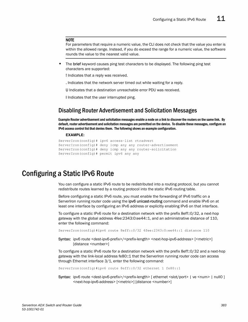
Configuring a Static IPv6 Route 11DRAFT: BROCADE CONFIDENTIAL
NOTEFor parameters that require a numeric value, the CLI does not check that the value you enter is within the allowed range. Instead, if you do exceed the range for a numeric value, the software rounds the value to the nearest valid value.
• The brief keyword causes ping test characters to be displayed. The following ping test characters are supported:
! Indicates that a reply was received.
. Indicates that the network server timed out while waiting for a reply.
U Indicates that a destination unreachable error PDU was received.
I Indicates that the user interrupted ping.
Disabling Router Advertisement and Solicitation MessagesExample Router advertisement and solicitation messages enable a node on a link to discover the routers on the same link. By default, router advertisement and solicitation messages are permitted on the device. To disable these messages, configure an IPv6 access control list that denies them. The following shows an example configuration.
EXAMPLE:
ServerIron(config)# ipv6 access-list rtradvertServerIron(config)# deny icmp any any router-advertisementServerIron(config)# deny icmp any any router-solicitationServerIron(config)# permit ipv6 any any
Configuring a Static IPv6 RouteYou can configure a static IPv6 route to be redistributed into a routing protocol, but you cannot redistribute routes learned by a routing protocol into the static IPv6 routing table.
Before configuring a static IPv6 route, you must enable the forwarding of IPv6 traffic on a ServerIron running router code using the ipv6 unicast-routing command and enable IPv6 on at least one interface by configuring an IPv6 address or explicitly enabling IPv6 on that interface.
To configure a static IPv6 route for a destination network with the prefix 8eff::0/32, a next-hop gateway with the global address 4fee:2343:0:ee44::1, and an administrative distance of 110, enter the following command:
ServerIron(config)#ipv6 route 8eff::0/32 4fee:2343:0:ee44::1 distance 110
Syntax: ipv6 route <dest-ipv6-prefix>/<prefix-length> <next-hop-ipv6-address> [<metric>] [distance <number>]
To configure a static IPv6 route for a destination network with the prefix 8eff::0/32 and a next-hop gateway with the link-local address fe80::1 that the ServerIron running router code can access through Ethernet interface 3/1, enter the following command:
ServerIron(config)#ipv6 route 8eff::0/32 ethernet 1 fe80::1
Syntax: ipv6 route <dest-ipv6-prefix>/<prefix-length> [ ethernet <slot/port> | ve <num> | null0 ] <next-hop-ipv6-address> [<metric>] [distance <number>]
ServerIron ADX Switch and Router Guide 38353-1001742-01
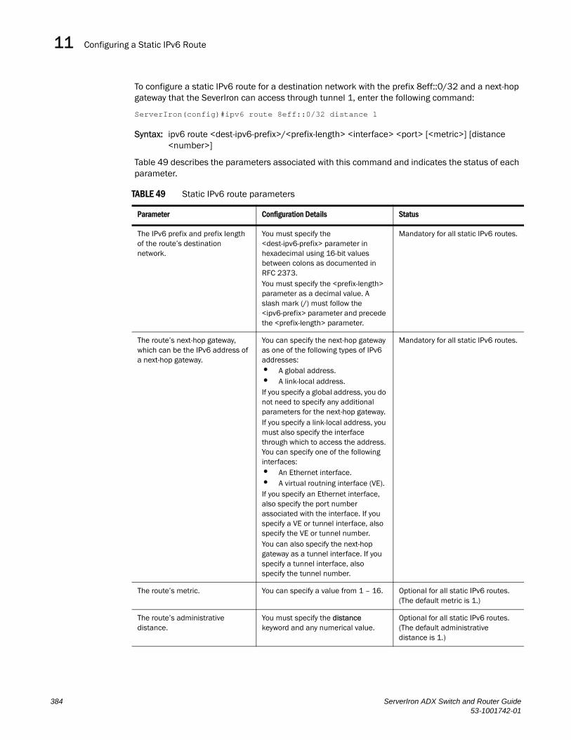
Configuring a Static IPv6 Route11DRAFT: BROCADE CONFIDENTIAL
To configure a static IPv6 route for a destination network with the prefix 8eff::0/32 and a next-hop gateway that the SeverIron can access through tunnel 1, enter the following command:
ServerIron(config)#ipv6 route 8eff::0/32 distance 1
Syntax: ipv6 route <dest-ipv6-prefix>/<prefix-length> <interface> <port> [<metric>] [distance <number>]
Table 49 describes the parameters associated with this command and indicates the status of each parameter.
TABLE 49 Static IPv6 route parameters
Parameter Configuration Details Status
The IPv6 prefix and prefix length of the route’s destination network.
You must specify the <dest-ipv6-prefix> parameter in hexadecimal using 16-bit values between colons as documented in RFC 2373.You must specify the <prefix-length> parameter as a decimal value. A slash mark (/) must follow the <ipv6-prefix> parameter and precede the <prefix-length> parameter.
Mandatory for all static IPv6 routes.
The route’s next-hop gateway, which can be the IPv6 address of a next-hop gateway.
You can specify the next-hop gateway as one of the following types of IPv6 addresses:• A global address.• A link-local address.If you specify a global address, you do not need to specify any additional parameters for the next-hop gateway.If you specify a link-local address, you must also specify the interface through which to access the address. You can specify one of the following interfaces:• An Ethernet interface.• A virtual routning interface (VE).If you specify an Ethernet interface, also specify the port number associated with the interface. If you specify a VE or tunnel interface, also specify the VE or tunnel number. You can also specify the next-hop gateway as a tunnel interface. If you specify a tunnel interface, also specify the tunnel number.
Mandatory for all static IPv6 routes.
The route’s metric. You can specify a value from 1 – 16. Optional for all static IPv6 routes. (The default metric is 1.)
The route’s administrative distance.
You must specify the distance keyword and any numerical value.
Optional for all static IPv6 routes. (The default administrative distance is 1.)
384 ServerIron ADX Switch and Router Guide53-1001742-01

ECMP Load Sharing for IPv6 11DRAFT: BROCADE CONFIDENTIAL
A metric is a value that the ServerIron uses when comparing this route to other static routes in the IPv6 static route table that have the same destination. The metric applies only to routes that the ServerIron ADX has already placed in the IPv6 static route table.
The administrative distance is a value that the ServerIron uses to compare this route with routes from other route sources that have the same destination. (The ServerIron performs this comparison before placing a route in the IPv6 route table.) This parameter does not apply to routes that are already in the IPv6 route table. In general, a low administrative distance indicates a preferred route. By default, static routes take precedence over routes learned by routing protocols. If you want a dynamic route to be chosen over a static route, you can configure the static route with a higher administrative distance than the dynamic route.
ECMP Load Sharing for IPv6The IPv6 route table selects the best route to a given destination from among the routes in the tables maintained by the configured routing protocols (OSPF, static, and so on). The IPv6 route table can contain more than one path to a given destination. When this occurs, the Brocade device selects the path with the lowest cost for insertion into the routing table. If more than one path with the lowest cost exists, all of these paths are inserted into the routing table, subject to the configured maximum number of load sharing paths (by default 4). The device uses Equal-Cost Multi-Path (ECMP) load sharing to select a path to a destination.
When a route is installed by routing protocols or configured static route for the first time, and the IPv6 route table contains multiple, equal-cost paths to that route, the device checks the IPv6 neighbor for each next hop. Every next hop where the link layer address has been resolved will be stored in hardware. The device will initiate neighbor discovery for the next hops whose link layer addresses are not resolved. The hardware will hash the packet and choose one of the paths. The number of paths would be updated in hardware as the link layer gets resolved for a next hop.
If the path selected by the device becomes unavailable, the IPv6 neighbor should change state and trigger the update of the destination in the hardware.
Brocade devices support network-based ECMP load-sharing methods for IPv6 traffic. The Brocade device distributes traffic across equal-cost paths based on a XOR of some bits from the MAC source address, MAC destination address, IPv6 source address, IPv6 destination address, IPv6 flow label, IPv6 next header. The software selects a path based on a calculation involving the maximum number of load-sharing paths allowed and the actual number of paths to the destination network. This is the default ECMP load-sharing method for IPv6.
You can manually disable or enable ECMP load sharing for IPv6 and specify the number of equal-cost paths the device can distribute traffic across. In addition, you can display information about the status of ECMP load-sharing on the device.
Disabling or Re-Enabling ECMP Load Sharing for IPv6ECMP load sharing for IPv6 is enabled by default. To disable the feature, enter the following command:
ServerIron(config)#no ipv6 load-sharing
If you want to re-enable the feature after disabling it, you must specify the number of load-sharing paths. The maximum number of paths the device supports is a value from 2 – 6. By entering a command such as the following, iPv6 load-sharing will be re-enabled.
ServerIron ADX Switch and Router Guide 38553-1001742-01
Configuring IPv6 ICMP Features11DRAFT: BROCADE CONFIDENTIAL
ServerIron(config)#ipv6 load-sharing 4
Syntax: [no] ipv6 load-sharing<num>
The <num> parameter specifies the number of paths and can be from 2 – 6. The default is 4.
Changing the Maximum Number of Load Sharing Paths for IPv6By default, IPv6 ECMP load sharing allows traffic to be balanced across up to four equal paths. You can change the maximum number of paths the device supports to a value from 2 – 6.
To change the number of ECMP load sharing paths for IPv6, enter a command such as the following:
ServerIron(config)# ipv6 load-sharing 6
Syntax: [no] ipv6 load-sharing [<num>]
The <num> parameter specifies the number of paths and can be from 2 – 6. The default is 4.
Enabling Support for Network-Based ECMP Load Sharing for IPv6Network-based ECMP load sharing is supported. In this configuration, traffic is distributed across equal-cost paths based on the destination network address. Routes to each network are stored in CAM and accessed when a path to a network is required. Because multiple hosts are likely to reside on a network, this method uses fewer CAM entries.
Displaying ECMP Load-Sharing Information for IPv6To display the status of ECMP load sharing for IPv6, enter the following command:
ServerIron#show ipv6Global Settings unicast-routing enabled, hop-limit 64 No Inbound Access List Set No Outbound Access List Set Prefix-based IPv6 Load-sharing is Enabled, Number of load share paths: 4
Syntax: show ipv6
Configuring IPv6 ICMP FeaturesAs with the Internet Control Message Protocol (ICMP) for IPv4, ICMP for IPv6 provides error and informational messages. Brocade’s implementation of the stateless auto configuration, neighbor discovery, and path MTU discovery features use ICMP messages.
This section explains how to configure following IPv6 ICMP features on a ServerIron running router code:
• ICMP rate limiting
• ICMP redirects
386 ServerIron ADX Switch and Router Guide53-1001742-01

Configuring IPv6 ICMP Features 11DRAFT: BROCADE CONFIDENTIAL
Configuring ICMP Rate LimitingYou can limit the rate at which IPv6 ICMP error messages are sent out on a network. IPv6 ICMP implements a token bucket algorithm.
To illustrate how this algorithm works, imagine a virtual bucket that contains a number of tokens. Each token represents the ability to send one ICMP error message. Tokens are placed in the bucket at a specified interval until the maximum number of tokens allowed in the bucket is reached. For each error message that ICMP sends, a token is removed from the bucket. If ICMP generates a series of error messages, messages can be sent until the bucket is empty. If the bucket is empty of tokens, error messages cannot be sent until a new token is placed in the bucket.
You can adjust the following elements related to the token bucket algorithm:
• The interval at which tokens are added to the bucket. The default is 100 milliseconds.
• The maximum number of tokens in the bucket. The default is 10 tokens.
For example, to adjust the interval to 1000 milliseconds and the number of tokens to 100 tokens, enter the following command:
ServerIron(config)# ipv6 icmp error-interval 1000 100
Syntax: ipv6 icmp error-interval <interval> [<number-of-tokens>]
The interval in milliseconds at which tokens are placed in the bucket can range from 0 – 2147483647. The maximum number of tokens stored in the bucket can range from 1 – 200.
NOTEIf you retain the default interval value or explicitly set the value to 100 milliseconds, output from the show run command does not include the setting of the ipv6 icmp error-interval command because the setting is the default.
Also, if you configure the interval value to a number that does not evenly divide into 100000 (100 milliseconds), the system rounds up the value to a next higher value that does divide evenly into 100000. For example, if you specify an interval value of 150, the system rounds up the value to 200.
ICMP rate limiting is enabled by default. To disable ICMP rate limiting, set the interval to zero.
Disabling or Reenabling ICMP Redirect MessagesYou can disable or re-enable the sending of ICMP redirect messages by a ServerIron. By default, a ServerIron can send an ICMP redirect message to a neighboring host to inform it of a better first-hop router on a path to a destination. No further configuration is required to enable the sending of ICMP redirect messages. (For more information about how ICMP redirect messages are implemented for IPv6, see “Configuring IPv6 Neighbor Discovery” on page 388.)
NOTEThis feature is supported on Virtual Ethernet (VE) interfaces only.
For example, to disable the sending of ICMP redirect messages on Ethernet interface 3/1, enter the following commands:
ServerIron(config)#interface ethernet 3/1ServerIron(config-if-e1000-3/1)#no ipv6 redirects
Syntax: [no] ipv6 redirects
ServerIron ADX Switch and Router Guide 38753-1001742-01

Configuring IPv6 Neighbor Discovery11DRAFT: BROCADE CONFIDENTIAL
To re-enable the sending of ICMP redirect messages on Ethernet interface 3/1, enter the following commands:
ServerIron(config)#interface ethernet 3/1ServerIron(config-if-e1000-3/1)#ipv6 redirects
Use the show ipv6 interface <interface> <port-number> command to verify that the sending of ICMP redirect messages is enabled on a particular interface.
Configuring IPv6 Neighbor DiscoveryThe neighbor discovery feature for IPv6 uses IPv6 ICMP messages to do the following:
• Determine the link-layer address of a neighbor on the same link.
• Verify that a neighbor is reachable.
• Track neighbor routers.
An IPv6 host is required to listen for and recognize the following addresses that identify itself:
• Link-local address.
• Assigned unicast address.
• Loopback address.
• All-nodes multicast address.
• Solicited-node multicast address.
• Multicast address to all other groups to which it belongs.
You can adjust the following IPv6 neighbor discovery features:
• Neighbor solicitation messages for duplicate address detection.
• Router advertisement messages:
• Interval between router advertisement messages.
• Value that indicates a router is advertised as a default router (for use by all nodes on a given link).
• Prefixes advertised in router advertisement messages.
• Flags for host stateful autoconfiguration.
• Amount of time during which an IPv6 node considers a remote node reachable (for use by all nodes on a given link).
Configuration Notes
NOTEFor all solicitation and advertisement messages, Brocade uses seconds as the unit of measure instead of milliseconds.
• If you add a port to a port-based VLAN, and the port has IPv6 neighbor discovery configuration, the system will clean up the neighbor discovery configuration from the port and display the following message on the console:
ND6 port config on the new member ports removed
388 ServerIron ADX Switch and Router Guide53-1001742-01

Configuring IPv6 Neighbor Discovery 11DRAFT: BROCADE CONFIDENTIAL
• Neighbor discovery is not supported on tunnel interfaces.
Neighbor Solicitation and Advertisement MessagesNeighbor solicitation and advertisement messages enable a node to determine the link-layer address of another node (neighbor) on the same link. (This function is similar to the function provided by the Address Resolution Protocol [ARP] in IPv4.) For example, node 1 on a link wants to determine the link-layer address of node 2 on the same link. To do so, node 1, the source node, multicasts a neighbor solicitation message. The neighbor solicitation message, which has a value of 135 in the Type field of the ICMP packet header, contains the following information:
• Source address: IPv6 address of node 1 interface that sends the message.
• Destination address: solicited-node multicast address (FF02:0:0:0:0:1:FF00::/104) that corresponds the IPv6 address of node 2.
• Link-layer address of node 1.
• A query for the link-layer address of node 2.
After receiving the neighbor solicitation message from node 1, node 2 replies by sending a neighbor advertisement message, which has a value of 136 in the Type field of the ICMP packet header. The neighbor solicitation message contains the following information:
• Source address: IPv6 address of the node 2 interface that sends the message.
• Destination address: IPv6 address of node 1.
• Link-layer address of node 2.
After node 1 receives the neighbor advertisement message from node 2, nodes 1 and 2 can now exchange packets on the link.
After the link-layer address of node 2 is determined, node 1 can send neighbor solicitation messages to node 2 to verify that it is reachable. Also, nodes 1, 2, or any other node on the same link can send a neighbor advertisement message to the all-nodes multicast address (FF02::1) if there is a change in their link-layer address.
Router Advertisement and Solicitation MessagesRouter advertisement and solicitation messages enable a node on a link to discover the routers on the same link.
Each configured router interface on a link sends out a router advertisement message, which has a value of 134 in the Type field of the ICMP packet header, periodically to the all-nodes link-local multicast address (FF02::1).
A configured router interface can also send a router advertisement message in response to a router solicitation message from a node on the same link. This message is sent to the unicast IPv6 address of the node that sent the router solicitation message.
At system startup, a host on a link sends a router solicitation message to the all-routers multicast address (FF01). Sending a router solicitation message, which has a value of 133 in the Type field of the ICMP packet header, enables the host to automatically configure its IPv6 address immediately instead of awaiting the next periodic router advertisement message.
ServerIron ADX Switch and Router Guide 38953-1001742-01

Configuring IPv6 Neighbor Discovery11DRAFT: BROCADE CONFIDENTIAL
Because a host at system startup typically does not have a unicast IPv6 address, the source address in the router solicitation message is usually the unspecified IPv6 address (0:0:0:0:0:0:0:0). If the host has a unicast IPv6 address, the source address is the unicast IPv6 address of the host interface sending the router solicitation message.
Entering the ipv6 unicast-routing command automatically enables the sending of router advertisement messages on all configured router Ethernet interfaces. You can configure several router advertisement message parameters. For information about disabling the sending of router advertisement messages and the router advertisement parameters that you can configure, see “Enabling and Disabling IPv6 Router Advertisements” on page 394 and “Setting IPv6 Router Advertisement Parameters” on page 391.
Neighbor Redirect MessagesAfter forwarding a packet, by default, a router can send a neighbor redirect message to a host to inform it of a better first-hop router. The host receiving the neighbor redirect message will then readdress the packet to the better router.
A router sends a neighbor redirect message only for unicast packets, only to the originating node, and to be processed by the node.
A neighbor redirect message has a value of 137 in the Type field of the ICMP packet header.
Setting Neighbor Solicitation Parameters for Duplicate Address DetectionAlthough the stateless auto configuration feature assigns the 64-bit interface ID portion of an IPv6 address using the MAC address of the host’s NIC, duplicate MAC addresses can occur. Therefore, the duplicate address detection feature verifies that a unicast IPv6 address is unique before it is assigned to a host interface by the stateless auto configuration feature. Duplicate address detection verifies that a unicast IPv6 address is unique.
If duplicate address detection identifies a duplicate unicast IPv6 address, the address is not used. If the duplicate address is the link-local address of the host interface, the interface stops processing IPv6 packets.
NOTEDuplicate Address Detection (DAD) is not currently supported with IPv6 tunnels. Make sure tunnel endpoints do not have duplicate IP addresses.
You can configure the following neighbor solicitation message parameters that affect duplicate address detection while it verifies that a tentative unicast IPv6 address is unique:
• The number of consecutive neighbor solicitation messages that duplicate address detection sends on an interface. By default, duplicate address detection sends three neighbor solicitation messages without any follow-up messages.
• The interval in seconds at which duplicate address detection sends a neighbor solicitation message on an interface. By default, duplicate address detection sends a neighbor solicitation message every 1000 milliseconds.
For example, to change the number of neighbor solicitation messages sent on Ethernet interface 3/1 to two and the interval between the transmission of the two messages to 9 seconds, enter the following commands:
390 ServerIron ADX Switch and Router Guide53-1001742-01
Configuring IPv6 Neighbor Discovery 11DRAFT: BROCADE CONFIDENTIAL
ServerIron(config)# interface ethernet 3/1ServerIron(config-if-e1000-3/1)#ipv6 nd dad attempt 2ServerIron(config-if-e1000-3/1)# ipv6 nd ns-interval 9000
Syntax: [no] ipv6 nd dad attempt <number>
Syntax: [no] ipv6 nd ns-interval <number>
For the number of neighbor solicitation messages, specify a number from 0 – 255. The default is 3. Configuring a value of 0 disables duplicate address detection processing on the specified interface. To restore the number of messages to the default value, use the no form of this command.
For the interval between neighbor solicitation messages and the value for the retrans timer in router advertisements, specify a number from 0 – 4294967295 milliseconds. The default value for the interval between neighbor solicitation messages is 1000 milliseconds. The default value for the retrans timer is 0. Brocade does not recommend very short intervals in normal IPv6 operation. When a non-default value is configured, the configured time is both advertised and used by the router itself. To restore the default interval, use the no form of this command.
Setting IPv6 Router Advertisement ParametersYou can adjust the following parameters for router advertisement messages:
• The interval (in seconds) at which an interface sends router advertisement messages. By default, an interface sends a router advertisement message every 200 seconds.
• The "router lifetime" value, which is included in router advertisements sent from a particular interface. The value (in seconds) indicates if the router is advertised as a default router on this interface. If you set the value of this parameter to 0, the router is not advertised as a default router on an interface. If you set this parameter to a value that is not 0, the router is advertised as a default router on this interface. By default, the router lifetime value included in router advertisement messages sent from an interface is 1800 seconds.
• The hop limit to be advertised in the router advertisement.
When adjusting these parameter settings, Brocade recommends that the interval between router advertisement transmission be less than or equal to the router lifetime value if the router is advertised as a default router. For example, to adjust the interval of router advertisements to 300 seconds and the router lifetime value to 1900 seconds on Ethernet interface 3/1, enter the following commands:
ServerIron(config)# interface ethernet 3/1ServerIron(config-if-e1000-3/1)# ipv6 nd ra-interval 300ServerIron(config-if-e1000-3/1)# ipv6 nd ra-lifetime 1900ServerIron(config-if-e1000-3/1)# ipv6 nd ra-hop-limit 1
Here is another example with a specified range:
ServerIron(config)# interface ethernet 3/1ServerIron(config-if-e1000-3/1)# ipv6 nd ra-interval range 33 55ServerIron(config-if-e1000-3/1)# ipv6 nd ra-lifetime 1900ServerIron(config-if-e1000-3/1)# ipv6 nd ra-hop-limit 1
Syntax: [no] ipv6 nd ra-interval <number> | <min range value> <max range value>
Syntax: [no] ipv6 nd ra-lifetime <number>
Syntax: ipv6 nd ra-hop-limit <number>
ServerIron ADX Switch and Router Guide 39153-1001742-01

Configuring IPv6 Neighbor Discovery11DRAFT: BROCADE CONFIDENTIAL
<number> is a value from 0 – 255. The default is 64.
The ipv6 nd ra-interval <number> can be a value between 3 – 1800 seconds. The default is 200 seconds. The actual RA interval will be from .5 to 1.5 times the configured or default value. For example, in the above configuration, for ipv6 nd ra-interval 300, the range would be 150 – 450. To restore the default interval of 200 seconds, use the no form of the command.
The ipv6 nd ra-interval range <min range value> <max range value> command lets you specify a range of values instead of a single value:
The <min range value> specifies the minimum number of seconds allowed between sending unsolicited multicast router advertisements from the interface. The default is 0.33 times the <max range value> if the <max range value> is greater than or equal to 9 seconds. Otherwise, the default is the value specified by the <max range value>. The <min range value> can be a number between -3 – (.75 x <max range value>).
The <max range value> parameter specifies the maximum number of seconds allowed between sending unsolicited multicast router advertisements from the interface. This number can be between 4 – 1800 seconds and must be greater than the <min range value> x 1.33. The default is 600 seconds.
The ipv6 nd ra-lifetime <number> is a value between 0 – 9000 seconds. To restore the router lifetime value of 1800 seconds, use the no form of the command.
The ipv6 nd ra-hop-limit <number> is a value from 0 – 255. The default is 64.
NOTEBy default, router advertisements will always have the MTU option. To suppress the MTU option, use the following command at the Interface level of the CLI: ipv6 nd suppress-mtu-option.
Controlling Prefixes Advertised in IPv6 Router Advertisement MessagesBy default, router advertisement messages include prefixes configured as addresses on router interfaces using the ipv6 address command. You can use the ipv6 nd prefix-advertisement command to control exactly which prefixes are included in router advertisement messages. Along with which prefixes the router advertisement messages contain, you can also specify the following parameters:
• Valid lifetime—(Mandatory) The time interval (in seconds) in which the specified prefix is advertised as valid. The default is 2592000 seconds (30 days). When the timer expires, the prefix is no longer considered to be valid.
• Preferred lifetime—(Mandatory) The time interval (in seconds) in which the specified prefix is advertised as preferred. The default is 604800 seconds (7 days). When the timer expires, the prefix is no longer considered to be preferred.
• Onlink flag—(Optional) If this flag is set, the specified prefix is assigned to the link upon which it is advertised. Nodes sending traffic to addresses that contain the specified prefix consider the destination to be reachable on the local link.
• Autoconfiguration flag—(Optional) If this flag is set, the stateless auto configuration feature can use the specified prefix in the automatic configuration of 128-bit IPv6 addresses for hosts on the local link, provided the specified prefix is aggregatable, as specified in RFC 2374.
For example, to advertise the prefix 2001:e077:a487:7365::/64 in router advertisement messages sent out on Ethernet interface 3/1 with a valid lifetime of 1000 seconds, a preferred lifetime of 800 seconds, and the Onlink and Autoconfig flags set, enter the following commands:
392 ServerIron ADX Switch and Router Guide53-1001742-01

Configuring IPv6 Neighbor Discovery 11DRAFT: BROCADE CONFIDENTIAL
ServerIron(config)#interface ethernet 3/1ServerIron(config-if-e1000-3/1)#ipv6 nd prefix-advertisement 2001:e077:a487:7365::/64 1000 800 onlink autoconfig
Syntax: [no] ipv6 nd prefix-advertisement <ipv6-prefix>/<prefix-length> <valid-lifetime> <preferred-lifetime> [autoconfig] [onlink]
You must specify the <ipv6-prefix> parameter in hexadecimal using 16-bit values between colons as documented in RFC 2373.
You must specify the <prefix-length> parameter as a decimal value. A slash mark (/) must follow the <ipv6-prefix> parameter and precede the <prefix-length> parameter.
The valid lifetime and preferred lifetime is a numerical value between 0 – 4294967295 seconds. The default valid lifetime is 2592000 seconds (30 days), while the default preferred lifetime is 604800 seconds (7 days).
To remove a prefix from the router advertisement messages sent from a particular interface, use the no form of this command.
Setting Flags in IPv6 Router Advertisement MessagesAn IPv6 router advertisement message can include the following flags:
• Managed Address Configuration—This flag indicates to hosts on a local link if they should use the stateful autoconfiguration feature to get IPv6 addresses for their interfaces. If the flag is set, the hosts use stateful autoconfiguration to get addresses as well as non-IPv6-address information. If the flag is not set, the hosts do not use stateful autoconfiguration to get addresses and if the hosts can get non-IPv6-address information from stateful autoconfiguration is determined by the setting of the Other Stateful Configuration flag.
• Other Stateful Configuration—This flag indicates to hosts on a local link if they can get non-IPv6 address autoconfiguration information. If the flag is set, the hosts can use stateful autoconfiguration to get non-IPv6-address information.
NOTEWhen determining if hosts can use stateful autoconfiguration to get non-IPv6-address information, a set Managed Address Configuration flag overrides an unset Other Stateful Configuration flag. In this situation, the hosts can obtain nonaddress information. However, if the Managed Address Configuration flag is not set and the Other Stateful Configuration flag is set, then the setting of the Other Stateful Configuration flag is used.
By default, the Managed Address Configuration and Other Stateful Configuration flags are not set in router advertisement messages. For example, to set these flags in router advertisement messages sent from Ethernet interface 3/1, enter the following commands:
ServerIron(config)# interface ethernet 3/1ServerIron(config-if-e1000-3/1)# ipv6 nd managed-config-flagServerIron(config-if-e1000-3/1) ipv6 nd other-config-flagSyntax: [no] ipv6 nd managed-config-flag
Syntax: [no] ipv6 nd other-config-flag
To remove either flag from router advertisement messages sent on an interface, use the no form of the respective command.
ServerIron ADX Switch and Router Guide 39353-1001742-01

Configuring Static Neighbor Entries11DRAFT: BROCADE CONFIDENTIAL
Enabling and Disabling IPv6 Router AdvertisementsIf IPv6 unicast routing is enabled on an Ethernet interface, by default, this interface sends IPv6 router advertisement messages. However, by default, non-LAN interface types, for example, tunnel interfaces, do not send router advertisement messages.
To disable the sending of router advertisement messages on an Ethernet interface, enter commands such as the following:
ServerIron(config)#interface ethernet 3/1ServerIron(config-if-e1000-3/1)#ipv6 nd suppress-ra
To enable the sending of router advertisement messages on a tunnel interface, enter commands such as the following:
ServerIron(config)#interface tunnel 1ServerIron(config-tnif-1)#no ipv6 nd suppress-ra
Syntax: [no] ipv6 nd suppress-ra
Configuring Reachable Time for Remote IPv6 NodesYou can configure the duration (in seconds) that a router considers a remote IPv6 node reachable. By default, a router interface uses the value of 30 seconds.
The router advertisement messages sent by a router interface include the amount of time specified by the ipv6 nd reachable-time command so that nodes on a link use the same reachable time duration. By default, the messages include a default value of 0.
Brocade does not recommend configuring a short reachable time duration, because a short duration causes the IPv6 network devices to process the information at a greater frequency.
For example, to configure the reachable time of 40 seconds for Ethernet interface 3/1, enter the following commands:
ServerIron(config)#interface ethernet 3/1ServerIron(config-if-e1000-3/1)#ipv6 nd reachable-time 40
Syntax: [no] ipv6 nd reachable-time <seconds>
For the <seconds> parameter, specify a number from 0 – 3600 seconds. To restore the default time, use the no form of this command.
NOTEThe actual reachable time will be from .5 to 1.5 times the configured or default value.
Configuring Static Neighbor EntriesIn some special cases, a neighbor cannot be reached using the neighbor discovery feature. In this situation, you can add a static entry to the IPv6 neighbor discovery cache, which causes a neighbor to be reachable at all times without using neighbor discovery. (A static entry in the IPv6 neighbor discovery cache functions like a static ARP entry in IPv4.)
NOTEA port that has a statically assigned IPv6 entry cannot be added to a VLAN.
394 ServerIron ADX Switch and Router Guide53-1001742-01

Limiting the Number of Hops an IPv6 Packet Can Traverse 11DRAFT: BROCADE CONFIDENTIAL
NOTEStatic neighbor configurations will be cleared on secondary ports when a trunk is formed.
For example, to add a static entry for a neighbor with the IPv6 address 3001:ffe0:2678:47b and link-layer address 0004.6a2b.8641 that is reachable through Ethernet interface 3/1, enter the following command:
ServerIron(config)#ipv6 neighbor 3001:ffe0:2678:47b ethernet 3/1 0004.6a2b.8641
Syntax: [no] ipv6 neighbor <ipv6-address> ethernet <port> | ve <ve-number> [ethernet <port>] <link-layer-address>
The <ipv6-address> parameter specifies the address of the neighbor.
The ethernet | ve parameter specifies the interface through which to reach a neighbor. If you specify an Ethernet interface, specify the port number of the Ethernet interface. If you specify a VE, specify the VE number and then the Ethernet port numbers associated with the VE. The link-layer address is a 48-bit hardware address of the neighbor.
If you attempt to add an entry that already exists in the neighbor discovery cache, the software changes the already existing entry to a static entry.
To remove a static IPv6 entry from the IPv6 neighbor discovery cache, use the no form of this command.
Limiting the Number of Hops an IPv6 Packet Can TraverseBy default, the maximum number of hops an IPv6 packet can traverse is 64. You can change this value to between 0 – 255 hops. For example, to change the maximum number of hops to 70, enter the following command:
ServerIron(config)# ipv6 hop-limit 70
Syntax: [no] ipv6 hop-limit <number>
Use the no form of the command to restore the default value.
hop-limit 0 will transmit packets with default (64) hop limit.
<number> can be from 0 – 255.
Clearing IPv6 InformationYou can clear the following global IPv6 information:
• Entries from the IPv6 cache.
• Entries from the IPv6 neighbor table.
• IPv6 routes from the IPv6 route table.
• IPv6 traffic statistics.
• IPv6 address mapping statistics
ServerIron ADX Switch and Router Guide 39553-1001742-01

Clearing IPv6 Information11DRAFT: BROCADE CONFIDENTIAL
Clearing the IPv6 address from the CacheYou can clear the following IPv6 entries from the cache:
• IPv6 prefix.
• IPv6 address.
• Interface type.
For example, to remove entries for IPv6 address 2000:e0ff::1, enter the following command at the Privileged EXEC level or any of the Config levels of the CLI:
ServerIron# clear ipv6 cache 2000:e0ff::1
Syntax: clear ipv6 cache [<ipv6-prefix>/<prefix-length> | <ipv6-address> | ethernet <port> | tunnel <number> | ve <number>]
You must specify the <ipv6-prefix> parameter in hexadecimal using 16-bit values between colons as documented in RFC 2373. You must specify the <prefix-length> parameter as a decimal value. A slash mark (/) must follow the <ipv6-prefix> parameter and precede the <prefix-length> parameter.
You must specify the <ipv6-address> parameter in hexadecimal using 16-bit values between colons as documented in RFC 2373.
The ethernet | tunnel | ve parameter specifies the interfaces for which you can remove cache entries. If you specify an Ethernet interface, also specify the port number associated with the interface. If you specify a VE or tunnel interface, also specify the VE or tunnel number, respectively.
Clearing IPv6 Neighbor InformationYou can remove all entries from the IPv6 neighbor table or specify an entry based on the following:
• IPv6 prefix
• IPv6 address
• Interface type
For example, to remove entries for Ethernet interface 3/1, enter the following command at the Privileged EXEC level or any of the CONFIG levels of the CLI:
ServerIron# clear ipv6 neighbor ethernet 3/1Syntax: clear ipv6 neighbor [<ipv6-prefix>/<prefix-length> | <ipv6-address> | ethernet <port> |
ve <number>]
You must specify the <ipv6-prefix> parameter in hexadecimal using 16-bit values between colons as documented in RFC 2373. You must specify the <prefix-length> parameter as a decimal value. A slash mark (/) must follow the <ipv6-prefix> parameter and precede the <prefix-length> parameter.
You must specify the <ipv6-address> parameter in hexadecimal using 16-bit values between colons as documented in RFC 2373.
The ethernet | ve parameter specifies the interfaces for which you can remove cache entries. If you specify an Ethernet interface, also specify the port number associated with the interface. If you specify a VE, also specify the VE number.
396 ServerIron ADX Switch and Router Guide53-1001742-01
Displaying IPv6 Information 11DRAFT: BROCADE CONFIDENTIAL
Clearing IPv6 Routes from the IPv6 Route TableYou can clear all IPv6 routes or only those routes associated with a particular IPv6 prefix from the IPv6 route table and reset the routes.
For example, to clear IPv6 routes associated with the prefix 2000:7838::/32, enter the following command at the Privileged EXEC level or any of the Config levels of the CLI:
ServerIron#clear ipv6 route 2000:7838::/32
Syntax: clear ipv6 route [<ipv6-prefix>/<prefix-length>]
The <ipv6-prefix>/<prefix-length> parameter clears routes associated with a particular IPv6 prefix. You must specify the <ipv6-prefix> parameter in hexadecimal using 16-bit values between colons as documented in RFC 2373. You must specify the <prefix-length> parameter as a decimal value. A slash mark (/) must follow the <ipv6-prefix> parameter and precede the <prefix-length> parameter.
Clearing IPv6 Traffic StatisticsTo clear all IPv6 traffic statistics (reset all fields to zero), enter the following command at the Privileged EXEC level or any of the Config levels of the CLI:
ServerIron(config)#clear ipv6 traffic
Syntax: clear ipv6 traffic
Clearing the Mapping for an IPv6 addressThis command allows you to clear the mapping for the specified IPv6 address. You cannot use this command to clear static mappings.
ServerIron 850# clear address-map 2013:db8:0:f101::abcd Syntax: clear address-map <ipv6-address>Command to clear mapping for an IPv4 addressThis command enables the user to clear the mapping for the specified IPv4 address. Note that user cannot delete static mappings using this command.ServerIron 850#clear address-map 224.7.163.33 Syntax: clear address-map <ipv4-address>
Displaying IPv6 InformationYou can display output for the following global IPv6 parameters:
• IPv6 cache
• IPv6 interfaces
• IPv6 neighbors
• IPv6 route table
• Local IPv6 routers
• IPv6 TCP connections and the status of individual connections
• IPv6 traffic statistics
ServerIron ADX Switch and Router Guide 39753-1001742-01

Displaying IPv6 Information11DRAFT: BROCADE CONFIDENTIAL
Displaying IPv6 Cache InformationThe IPv6 cache contains an IPv6 host table that has indices to the next hop gateway and the router interface on which the route was learned.
To display IPv6 cache information, enter the following command at any CLI level:
Syntax: show ipv6 cache [<index-number> | <ipv6-prefix>/<prefix-length> | <ipv6-address> | ethernet <port> | ve <number> ]
The <index-number> parameter restricts the display to the entry for the specified index number and subsequent entries.
The <ipv6-prefix>/<prefix-length> parameter restricts the display to the entries for the specified IPv6 prefix. You must specify the <ipv6-prefix> parameter in hexadecimal using 16-bit values between colons as documented in RFC 2373. You must specify the <prefix-length> parameter as a decimal value. A slash mark (/) must follow the <ipv6-prefix> parameter and precede the <prefix-length> parameter.
The ethernet | ve parameter restricts the display to the entries for the specified interface. The <ipv6-address> parameter restricts the display to the entries for the specified IPv6 address. You must specify this parameter in hexadecimal using 16-bit values between colons as documented in RFC 2373.
If you specify an Ethernet interface, also specify the port number associated with the interface. If you specify a VE interface, also specify the VE number.
This display shows the following information:
TABLE 50 IPv6 cache information fields
This Field... Displays...
Total number of cache entries The number of entries in the cache table.
IPv6 Address The host IPv6 address.
Next Hop The next hop, which can be one of the following:• Direct – The next hop is directly connected to the router.• Local – The next hop is originated on this router.• <ipv6 address> – The IPv6 address of the next hop.
ServerIron# show ipv6 cacheTotal number of cache entries: 10 IPv6 Address Next Hop Port1 5000:2::2 LOCAL tunnel 22 2000:4::106 LOCAL ethe 3/23 2000:4::110 DIRECT ethe 3/24 2002:c0a8:46a::1 LOCAL ethe 3/25 5005::2e0:52ff:fe99:9737 LOCAL ethe 3/26 5005::ffff:ffff:feff:ffff LOCAL loopback 27 5005::c0a8:46a LOCAL tunnel 28 5005::c0a8:46a LOCAL tunnel 69 2999::1 LOCAL loopback 210 5005::2e0:52ff:fe99:9700 LOCAL ethe 3/1
398 ServerIron ADX Switch and Router Guide53-1001742-01

Displaying IPv6 Information 11DRAFT: BROCADE CONFIDENTIAL
Displaying IPv6 Interface InformationTo display IPv6 interface information, enter the following command at any CLI level:
Syntax: show ipv6 interface [<interface> [<port-number> |<number>]]
The <interface> parameter displays detailed information for a specified interface. For the interface, you can specify the Ethernet, loopback, tunnel, or VE keywords. If you specify an Ethernet interface, also specify the port number associated with the interface. If you specify a loopback, tunnel, or VE interface, also specify the number associated with the interface.
This display shows the following information:
Port The port on which the entry was learned.
TABLE 51 General IPv6 interface information fields
This Field... Displays...
Routing protocols A one-letter code that represents a routing protocol that can be enabled on an interface.
Interface The interface type, and the port number or number of the interface.
Status The status of the interface. The entry in the Status field will be either “up/up” or “down/down”.
Routing The routing protocols enabled on the interface.
Global Unicast Address The global unicast address of the interface.
TABLE 50 IPv6 cache information fields (Continued)
This Field... Displays...
ServerIron# show ipv6 interfaceRouting Protocols : O - OSPFInterface Status Routing Global Unicast AddressEthernet 3/3 down/down OEthernet 3/5 down/downEthernet 3/17 up/up 2017::c017:101/64Ethernet 3/19 up/up 2019::c019:101/64VE 4 down/downVE 14 up/up 2024::c060:101/64Loopback 1 up/up ::1/128Loopback 2 up/up 2005::303:303/128Loopback 3 up/up
ServerIron ADX Switch and Router Guide 39953-1001742-01

Displaying IPv6 Information11DRAFT: BROCADE CONFIDENTIAL
To display detailed information for a specific interface, enter a command such as the following at any CLI level:
This display shows the following information:
TABLE 52 Detailed IPv6 interface information fields
This Field... Displays...
Interface/line protocol status The status of interface and line protocol. If you have disabled the interface with the disable command, the status will be “administratively down”. Otherwise, the status is either “up” or “down”.
IPv6 status/link-local address The status of IPv6. The status is either “enabled” or “disabled”.Displays the link-local address, if one is configured for the interface.
Global unicast address(es) Displays the global unicast address(es), if one or more are configured for the interface.
Joined group address(es) The multicast address(es) that a router interface listens for and recognizes.
MTU The setting of the maximum transmission unit (MTU) configured for the IPv6 interface. The MTU is the maximum length an IPv6 packet can have to be transmitted on the interface. If an IPv6 packet is longer than an MTU, the host that originated the packet fragments the packet and transmits its contents in multiple packets that are shorter than the configured MTU.
ICMP The setting of the ICMP redirect parameter for the interface.
ND The setting of the various neighbor discovery parameters for the interface.
Access List The inbound and outbound access control lists applied to the interface.
Routing protocols The routing protocols enabled on the interface.
ServerIron# show ipv6 interface ethernet 3/1Interface Ethernet 3/1 is up, line protocol is up IPv6 is enabled, link-local address is fe80::2e0:52ff:fe99:97 Global unicast address(es): Joined group address(es): ff02::9 ff02::1:ff99:9700 ff02::2 ff02::1 MTU is 1500 bytes ICMP redirects are enabled ND DAD is enabled, number of DAD attempts: 3 ND reachable time is 30 seconds ND advertised reachable time is 0 seconds ND retransmit interval is 1 seconds ND advertised retransmit interval is 0 seconds ND router advertisements are sent every 200 seconds ND router advertisements live for 1800 seconds No Inbound Access List Set No Outbound Access List Set
400 ServerIron ADX Switch and Router Guide53-1001742-01

Displaying IPv6 Information 11DRAFT: BROCADE CONFIDENTIAL
Displaying IPv6 Neighbor InformationYou can display the IPv6 neighbor table, which contains an entry for each IPv6 neighbor with which the router exchanges IPv6 packets.
To display the IPv6 neighbor table, enter the following command at any CLI level:
Syntax: show ipv6 neighbor [<ipv6-prefix>/<prefix-length> | <ipv6-address> | <interface> [<port> |<number>]]
The <ipv6-prefix>/<prefix-length> parameters restrict the display to the entries for the specified IPv6 prefix. You must specify the <ipv6-prefix> parameter in hexadecimal using 16-bit values between colons as documented in RFC 2373. You must specify the <prefix-length> parameter as a decimal value. A slash mark (/) must follow the <ipv6-prefix> parameter and precede the <prefix-length> parameter.
The <ipv6-address> parameter restricts the display to the entries for the specified IPv6 address. You must specify this parameter in hexadecimal using 16-bit values between colons as documented in RFC 2373.
The <interface> parameter restricts the display to the entries for the specified router interface. For this parameter, you can specify the Ethernet or VE keywords. If you specify an Ethernet interface, also specify the port number associated with the interface. If you specify a VE interface, also specify the VE number.
This display shows the following information:
TABLE 53 IPv6 neighbor information fields
This Field... Displays...
Total number of neighbor entries
The total number of entries in the IPv6 neighbor table.
IPv6 Address The 128-bit IPv6 address of the neighbor.
Link-Layer Address The 48-bit interface ID of the neighbor.
State The current state of the neighbor. Possible states are as follows:• INCOMPLETE – Address resolution of the entry is being performed.• *REACH – The static forward path to the neighbor is functioning
properly.• REACH – The forward path to the neighbor is functioning properly.• STALE – This entry has remained unused for the maximum interval.
While stale, no action takes place until a packet is sent.• DELAY – This entry has remained unused for the maximum interval, and
a packet was sent before another interval elapsed. • PROBE – Neighbor solicitation are transmitted until a reachability
confirmation is received.
ServerIron(config)# show ipv6 neighborTotal number of Neighbor entries: 3 IPv6 Address LinkLayer-Addr State Age Port vlan IsR 5555::55 0002.0002.0002 *REACH0 e 3/11 - 02000:4::110 00e0.5291.bb37 REACH 20 e 3/1 5 1fe80::2e0:52ff:fe91:bb37 00e0.5291.bb37 DELAY 1 e 3/2 4 1fe80::2e0:52ff:fe91:bb40 00e0.5291.bb40 STALE 5930e 3/3 5 1
ServerIron ADX Switch and Router Guide 40153-1001742-01
Displaying IPv6 Information11DRAFT: BROCADE CONFIDENTIAL
Displaying the IPv6 Route Table To display the IPv6 route table, enter the following command at any CLI level:
Syntax: show ipv6 route [<ipv6-address> | <ipv6-prefix>/<prefix-length> | connect | ospf | static | summary]
The <ipv6-address> parameter restricts the display to the entries for the specified IPv6 address. You must specify the <ipv6-address> parameter in hexadecimal using 16-bit values between colons as documented in RFC 2373.
The <ipv6-prefix>/<prefix-length> parameters restrict the display to the entries for the specified IPv6 prefix. You must specify the <ipv6-prefix> parameter in hexadecimal using 16-bit values between colons as documented in RFC 2373. You must specify the <prefix-length> parameter as a decimal value. A slash mark (/) must follow the <ipv6-prefix> parameter and precede the <prefix-length> parameter.
The connect keyword restricts the display to entries for directly connected interface IPv6 routes.
The ospf keyword restricts the display to entries for OSPFv3 routes.
The static keyword restricts the display to entries for static IPv6 routes.
The summary keyword displays a summary of the prefixes and different route types.
Age The number of seconds the entry has remained unused. If this value remains unused for the number of seconds specified by the ipv6 nd reachable-time command (the default is 30 seconds), the entry is removed from the table.
Port The physical port on which the entry was learned.
vlan The VLAN on which the entry was learned.
IsR Determines if the neighbor is a router or host:0 – Indicates that the neighbor is a host.1 – Indicates that the neighbor is a router.
TABLE 53 IPv6 neighbor information fields
This Field... Displays...
ServerIron# show ipv6 routeIPv6 Routing Table - 7 entries:Type Codes: C - Connected, S - Static, O - OSPFOSPF Sub Type Codes: O - Intra, Oi - Inter, O1 - Type1 external, O2 - Type2 externalType IPv6 Prefix Next Hop Router Interface Dis/MetricC 2000:4::/64 :: ethe 3/2 0/0S 2002::/16 :: tunnel 6 1/1S 2002:1234::/32 :: tunnel 6 1/1C 2002:c0a8:46a::/64 :: ethe 3/2 0/0C 2999::1/128 :: loopback 2 0/0O 2999::2/128 fe80::2e0:52ff:fe91:bb37 ethe 3/2 110/1C 5000:2::/64 :: tunnel 2 0/0
402 ServerIron ADX Switch and Router Guide53-1001742-01

Displaying IPv6 Information 11DRAFT: BROCADE CONFIDENTIAL
The following table lists the information displayed by the show ipv6 route command.
To display a summary of the IPv6 route table, enter the following command at any CLI level:
The following table lists the information displayed by the show ipv6 route summary command:
Displaying Local IPv6 RoutersThe Brocade device can function as an IPv6 host, instead of an IPv6 router, if you configure IPv6 addresses on its interfaces but don’t enable IPv6 routing using the ipv6 unicast-routing command.
From the IPv6 host, you can display information about IPv6 routers to which the host is connected. The host learns about the routers through their router advertisement messages. To display information about the IPv6 routers connected to an IPv6 host, enter the following command at any CLI level:
Syntax: show ipv6 router
TABLE 54 IPv6 route table fields
This Field... Displays...
Number of entries The number of entries in the IPv6 route table.
Type The route type, which can be one of the following:• C – The destination is directly connected to the router. • S – The route is a static route.• R – The route is learned from RIPng.• O – The route is learned from OSPFv3.
IPv6 Prefix The destination network of the route.
Next-Hop Router The next-hop router.
Interface The interface through which this router sends packets to reach the route's destination.
Dis/Metric The route’s administrative distance and metric value.
TABLE 55 IPv6 route table summary fields
This Field... Displays...
Number of entries The number of entries in the IPv6 route table.
Number of route types The number of entries for each route type.
Number of prefixes A summary of prefixes in the IPv6 route table, sorted by prefix length.
ServerIron# show ipv6 route summaryIPv6 Routing Table - 7 entries: 4 connected, 2 static, 1 OSPF Number of prefixes: /16: 1 /32: 1 /64: 3 /128: 2
ServerIron# show ipv6 routerRouter fe80::2e0:80ff:fe46:3431 on Ethernet 50, last update 0 minHops 64, Lifetime 1800 secReachable time 0 msec, Retransmit time 0 msec
ServerIron ADX Switch and Router Guide 40353-1001742-01

Displaying IPv6 Information11DRAFT: BROCADE CONFIDENTIAL
If you configure your Brocade device to function as an IPv6 router (you configure IPv6 addresses on its interfaces and enable IPv6 routing using the ipv6 unicast-routing command) and you enter the show ipv6 router command, you will receive the following output:
Meaningful output for this command is generated for Brocade devices configured to function as IPv6 hosts only.
This display shows the following information:
Displaying IPv6 TCP InformationYou can display the following IPv6 TCP information:
• General information about each TCP connection on the router, including the percentage of free memory for each of the internal TCP buffers.
• Detailed information about a specified TCP connection.
TABLE 56 IPv6 local router information fields
This Field... Displays...
Router <ipv6 address> on <interface> <port>
The IPv6 address for a particular router interface.
Last update The amount of elapsed time (in minutes) between the current and previous updates received from a router.
Hops The default value that should be included in the Hop Count field of the IPv6 header for outgoing IPv6 packets. The hops value applies to the router for which you are displaying information and should be followed by IPv6 hosts attached to the router. A value of 0 indicates that the router leaves this field unspecified.
Lifetime The amount of time (in seconds) that the router is useful as the default router.
Reachable time The amount of time (in milliseconds) that a router assumes a neighbor is reachable after receiving a reachability confirmation. The reachable time value applies to the router for which you are displaying information and should be followed by IPv6 hosts attached to the router. A value of 0 indicates that the router leaves this field unspecified.
Retransmit time The amount of time (in milliseconds) between retransmissions of neighbor solicitation messages. The retransmit time value applies to the router for which you are displaying information and should be followed by IPv6 hosts attached to the router. A value of 0 indicates that the router leaves this field unspecified.
No IPv6 router in table
404 ServerIron ADX Switch and Router Guide53-1001742-01

Displaying IPv6 Information 11DRAFT: BROCADE CONFIDENTIAL
To display general information about each TCP connection on the router, enter the following command at any CLI level:
Syntax: show ipv6 tcp connections
This display shows the following information:
TABLE 57 General IPv6 TCP connection fields
This Field... Displays...
Local IP address:port The IPv4 or IPv6 address and port number of the local router interface over which the TCP connection occurs.
Remote IP address:port The IPv4 or IPv6 address and port number of the remote router interface over which the TCP connection occurs.
TCP state The state of the TCP connection. Possible states include the following:• LISTEN – Waiting for a connection request.• SYN-SENT – Waiting for a matching connection request after having sent
a connection request.• SYN-RECEIVED – Waiting for a confirming connection request
acknowledgment after having both received and sent a connection request.
• ESTABLISHED – Data can be sent and received over the connection. This is the normal operational state of the connection.
• FIN-WAIT-1 – Waiting for a connection termination request from the remote TCP, or an acknowledgment of the connection termination request previously sent.
• FIN-WAIT-2 – Waiting for a connection termination request from the remote TCP.
• CLOSE-WAIT – Waiting for a connection termination request from the local user.
• CLOSING – Waiting for a connection termination request acknowledgment from the remote TCP.
• LAST-ACK – Waiting for an acknowledgment of the connection termination request previously sent to the remote TCP (which includes an acknowledgment of its connection termination request).
• TIME-WAIT – Waiting for enough time to pass to be sure the remote TCP received the acknowledgment of its connection termination request.
• CLOSED – There is no connection state.
ServerIron# show ipv6 tcp connectionsLocal IP address:port <-> Remote IP address:port TCP state192.168.182.110:23 <-> 192.168.8.186:4933 ESTABLISHED192.168.182.110:8218 <-> 192.168.182.106:179 ESTABLISHED192.168.182.110:8039 <-> 192.168.2.119:179 SYN-SENT192.168.182.110:8159 <-> 192.168.2.102:179 SYN-SENT2000:4::110:179 <-> 2000:4::106:8222 ESTABLISHED (1440)Total 5 TCP connections
TCP MEMORY USAGE PERCENTAGEFREE TCP = 98 percentFREE TCP QUEUE BUFFER = 99 percentFREE TCP SEND BUFFER = 97 percentFREE TCP RECEIVE BUFFER = 100 percentFREE TCP OUT OF SEQUENCE BUFFER = 100 percent
ServerIron ADX Switch and Router Guide 40553-1001742-01

Displaying IPv6 Information11DRAFT: BROCADE CONFIDENTIAL
To display detailed information about a specified TCP connection, enter a command such as the following at any CLI level:
Syntax: show ipv6 tcp status <local-ip-address> <local-port-number> <remote-ip-address> <remote-port-number>
The <local-ip-address> parameter can be the IPv4 or IPv6 address of the local interface over which the TCP connection is taking place.
The <local-port-number> parameter is the local port number over which a TCP connection is taking place.
The <remote-ip-address> parameter can be the IPv4 or IPv6 address of the remote interface over which the TCP connection is taking place.
The <remote-port-number> parameter is the local port number over which a TCP connection is taking place.
This display shows the following information:
FREE TCP = <percentage> The percentage of free TCP control block (TCP) space.
FREE TCP QUEUE BUFFER = <percentage>
The percentage of free TCP queue buffer space.
FREE TCP SEND BUFFER = <percentage>
The percentage of free TCP send buffer space.
FREE TCP RECEIVE BUFFER = <percentage>
The percentage of free TCP receive buffer space.
FREE TCP OUT OF SEQUENCE BUFFER = <percentage>
The percentage of free TCP out of sequence buffer space.
TABLE 58 Specific IPv6 TCP connection fields
This Field... Displays...
TCP = <location> The location of the TCP.
TABLE 57 General IPv6 TCP connection fields (Continued)
This Field... Displays...
ServerIron# show ipv6 tcp status 2000:4::110 179 2000:4::106 8222TCP: TCP = 0x217fc300TCP: 2000:4::110:179 <-> 2000:4::106:8222: state: ESTABLISHED Port: 1 Send: initial sequence number = 242365900 Send: first unacknowledged sequence number = 242434080 Send: current send pointer = 242434080 Send: next sequence number to send = 242434080 Send: remote received window = 16384 Send: total unacknowledged sequence number = 0 Send: total used buffers 0 Receive: initial incoming sequence number = 740437769 Receive: expected incoming sequence number = 740507227 Receive: received window = 16384 Receive: bytes in receive queue = 0 Receive: congestion window = 1459
406 ServerIron ADX Switch and Router Guide53-1001742-01

Displaying IPv6 Information 11DRAFT: BROCADE CONFIDENTIAL
<local-ip-address> <local-port-number> <remote-ip-address> <remote-port-number> <state> <port>
This field provides a general summary of the following:• The local IPv4 or IPv6 address and port
number.• The remote IPv4 or IPv6 address and port
number.• The state of the TCP connection. For
information on possible states, see Table on page 405.
• The port numbers of the local interface.
Send: initial sequence number = <number> The initial sequence number sent by the local router.
Send: first unacknowledged sequence number = <number> The first unacknowledged sequence number sent by the local router.
Send: current send pointer = <number> The current send pointer.
Send: next sequence number to send = <number> The next sequence number sent by the local router.
Send: remote received window = <number> The size of the remote received window.
Send: total unacknowledged sequence number = <number> The total number of unacknowledged sequence numbers sent by the local router.
Send: total used buffers <number> The total number of buffers used by the local router in setting up the TCP connection.
Receive: initial incoming sequence number = <number> The initial incoming sequence number received by the local router.
Receive: expected incoming sequence number = <number> The incoming sequence number expected by the local router.
Receive: received window = <number> The size of the local router’s receive window.
Receive: bytes in receive queue = <number> The number of bytes in the local router’s receive queue.
Receive: congestion window = <number> The size of the local router’s receive congestion window.
TABLE 58 Specific IPv6 TCP connection fields (Continued)
This Field... Displays...
ServerIron ADX Switch and Router Guide 40753-1001742-01
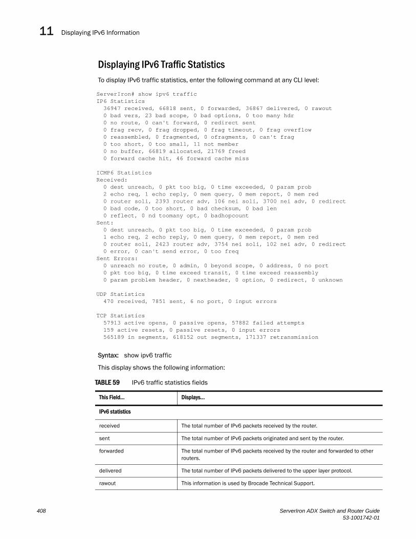
Displaying IPv6 Information11DRAFT: BROCADE CONFIDENTIAL
Displaying IPv6 Traffic StatisticsTo display IPv6 traffic statistics, enter the following command at any CLI level:
Syntax: show ipv6 traffic
This display shows the following information:
TABLE 59 IPv6 traffic statistics fields
This Field... Displays...
IPv6 statistics
received The total number of IPv6 packets received by the router.
sent The total number of IPv6 packets originated and sent by the router.
forwarded The total number of IPv6 packets received by the router and forwarded to other routers.
delivered The total number of IPv6 packets delivered to the upper layer protocol.
rawout This information is used by Brocade Technical Support.
ServerIron# show ipv6 trafficIP6 Statistics 36947 received, 66818 sent, 0 forwarded, 36867 delivered, 0 rawout 0 bad vers, 23 bad scope, 0 bad options, 0 too many hdr 0 no route, 0 can't forward, 0 redirect sent 0 frag recv, 0 frag dropped, 0 frag timeout, 0 frag overflow 0 reassembled, 0 fragmented, 0 ofragments, 0 can't frag 0 too short, 0 too small, 11 not member 0 no buffer, 66819 allocated, 21769 freed 0 forward cache hit, 46 forward cache miss
ICMP6 StatisticsReceived: 0 dest unreach, 0 pkt too big, 0 time exceeded, 0 param prob 2 echo req, 1 echo reply, 0 mem query, 0 mem report, 0 mem red 0 router soli, 2393 router adv, 106 nei soli, 3700 nei adv, 0 redirect 0 bad code, 0 too short, 0 bad checksum, 0 bad len 0 reflect, 0 nd toomany opt, 0 badhopcountSent: 0 dest unreach, 0 pkt too big, 0 time exceeded, 0 param prob 1 echo req, 2 echo reply, 0 mem query, 0 mem report, 0 mem red 0 router soli, 2423 router adv, 3754 nei soli, 102 nei adv, 0 redirect 0 error, 0 can't send error, 0 too freqSent Errors: 0 unreach no route, 0 admin, 0 beyond scope, 0 address, 0 no port 0 pkt too big, 0 time exceed transit, 0 time exceed reassembly 0 param problem header, 0 nextheader, 0 option, 0 redirect, 0 unknown
UDP Statistics 470 received, 7851 sent, 6 no port, 0 input errors
TCP Statistics 57913 active opens, 0 passive opens, 57882 failed attempts 159 active resets, 0 passive resets, 0 input errors 565189 in segments, 618152 out segments, 171337 retransmission
408 ServerIron ADX Switch and Router Guide53-1001742-01

Displaying IPv6 Information 11DRAFT: BROCADE CONFIDENTIAL
bad vers The number of IPv6 packets dropped by the router because the version number is not 6.
bad scope The number of IPv6 packets dropped by the router because of a bad address scope.
bad options The number of IPv6 packets dropped by the router because of bad options.
too many hdr The number of IPv6 packets dropped by the router because the packets had too many headers.
no route The number of IPv6 packets dropped by the router because there was no route.
can’t forward The number of IPv6 packets the router could not forward to another router.
redirect sent This information is used by Brocade Technical Support.
frag recv The number of fragments received by the router.
frag dropped The number of fragments dropped by the router.
frag timeout The number of fragment timeouts that occurred.
frag overflow The number of fragment overflows that occurred.
reassembled The number of fragmented IPv6 packets that the router reassembled.
fragmented The number of IPv6 packets fragmented by the router to accommodate the MTU of this router or of another device.
ofragments The number of output fragments generated by the router.
can’t frag The number of IPv6 packets the router could not fragment.
too short The number of IPv6 packets dropped because they are too short.
too small The number of IPv6 packets dropped because they don’t have enough data.
not member The number of IPv6 packets dropped because the recipient is not a member of a multicast group.
no buffer The number of IPv6 packets dropped because there is no buffer available.
forward cache miss The number of IPv6 packets received for which there is no corresponding cache entry.
ICMP6 statistics Some ICMP statistics apply to both Received and Sent, some apply to Received only, some apply to Sent only, and some apply to Sent Errors only.
Applies to Received and Sent
dest unreach The number of Destination Unreachable messages sent or received by the router.
pkt too big The number of Packet Too Big messages sent or received by the router.
time exceeded The number of Time Exceeded messages sent or received by the router.
param prob The number of Parameter Problem messages sent or received by the router.
echo req The number of Echo Request messages sent or received by the router.
TABLE 59 IPv6 traffic statistics fields (Continued)
This Field... Displays...
ServerIron ADX Switch and Router Guide 40953-1001742-01
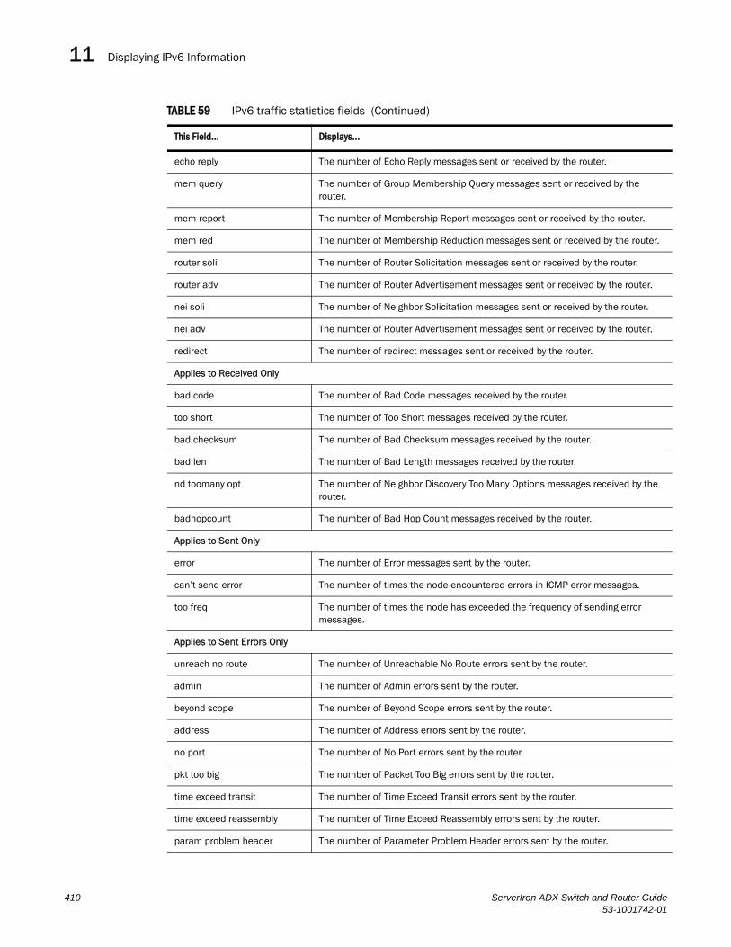
Displaying IPv6 Information11DRAFT: BROCADE CONFIDENTIAL
echo reply The number of Echo Reply messages sent or received by the router.
mem query The number of Group Membership Query messages sent or received by the router.
mem report The number of Membership Report messages sent or received by the router.
mem red The number of Membership Reduction messages sent or received by the router.
router soli The number of Router Solicitation messages sent or received by the router.
router adv The number of Router Advertisement messages sent or received by the router.
nei soli The number of Neighbor Solicitation messages sent or received by the router.
nei adv The number of Router Advertisement messages sent or received by the router.
redirect The number of redirect messages sent or received by the router.
Applies to Received Only
bad code The number of Bad Code messages received by the router.
too short The number of Too Short messages received by the router.
bad checksum The number of Bad Checksum messages received by the router.
bad len The number of Bad Length messages received by the router.
nd toomany opt The number of Neighbor Discovery Too Many Options messages received by the router.
badhopcount The number of Bad Hop Count messages received by the router.
Applies to Sent Only
error The number of Error messages sent by the router.
can’t send error The number of times the node encountered errors in ICMP error messages.
too freq The number of times the node has exceeded the frequency of sending error messages.
Applies to Sent Errors Only
unreach no route The number of Unreachable No Route errors sent by the router.
admin The number of Admin errors sent by the router.
beyond scope The number of Beyond Scope errors sent by the router.
address The number of Address errors sent by the router.
no port The number of No Port errors sent by the router.
pkt too big The number of Packet Too Big errors sent by the router.
time exceed transit The number of Time Exceed Transit errors sent by the router.
time exceed reassembly The number of Time Exceed Reassembly errors sent by the router.
param problem header The number of Parameter Problem Header errors sent by the router.
TABLE 59 IPv6 traffic statistics fields (Continued)
This Field... Displays...
410 ServerIron ADX Switch and Router Guide53-1001742-01

Displaying IPv6 Information 11DRAFT: BROCADE CONFIDENTIAL
Displaying IPv4 to IPv6 Address MappingThis command displays which IPv4 address is mapped to a specified IPv6 address.
ServerIron 850# show ipv6 address-map 2013:db8:0:f101::abcd ********************************************V6-V4 Map entry for V6 2013:db8:0:f101::abcd********************************************Mapped IPv4 = 224.7.163.33Type = StaticRef count = 1V4 fwd link= 00000000V6 fwd link= 00000000
nextheader The number of Next Header errors sent by the router.
option The number of Option errors sent by the router.
redirect The number of Redirect errors sent by the router.
unknown The number of Unknown errors sent by the router.
UDP statistics
received The number of UDP packets received by the router.
sent The number of UDP packets sent by the router.
no port The number of UDP packets dropped because the packet did not contain a valid UDP port number.
input errors This information is used by Brocade Technical Support.
TCP statistics
active opens The number of TCP connections opened by the router by sending a TCP SYN to another device.
passive opens The number of TCP connections opened by the router in response to connection requests (TCP SYNs) received from other devices.
failed attempts This information is used by Brocade Technical Support.
active resets The number of TCP connections the router reset by sending a TCP RESET message to the device at the other end of the connection.
passive resets The number of TCP connections the router reset because the device at the other end of the connection sent a TCP RESET message.
input errors This information is used by Brocade Technical Support.
in segments The number of TCP segments received by the router.
out segments The number of TCP segments sent by the router.
retransmission The number of segments that the router retransmitted because the retransmission timer for the segment had expired before the device at the other end of the connection had acknowledged receipt of the segment.
TABLE 59 IPv6 traffic statistics fields (Continued)
This Field... Displays...
ServerIron ADX Switch and Router Guide 41153-1001742-01
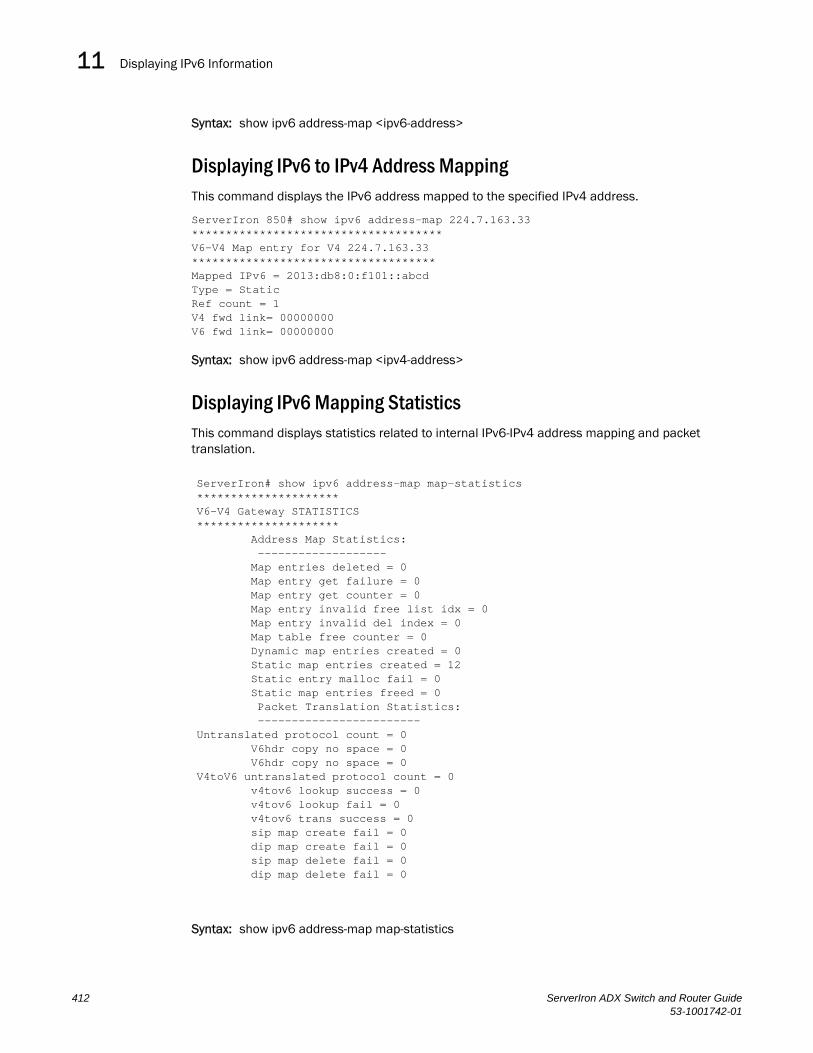
Displaying IPv6 Information11DRAFT: BROCADE CONFIDENTIAL
Syntax: show ipv6 address-map <ipv6-address>
Displaying IPv6 to IPv4 Address MappingThis command displays the IPv6 address mapped to the specified IPv4 address.
ServerIron 850# show ipv6 address-map 224.7.163.33 *************************************V6-V4 Map entry for V4 224.7.163.33************************************Mapped IPv6 = 2013:db8:0:f101::abcdType = StaticRef count = 1V4 fwd link= 00000000V6 fwd link= 00000000
Syntax: show ipv6 address-map <ipv4-address>
Displaying IPv6 Mapping StatisticsThis command displays statistics related to internal IPv6-IPv4 address mapping and packet translation.
Syntax: show ipv6 address-map map-statistics
ServerIron# show ipv6 address-map map-statistics*********************V6-V4 Gateway STATISTICS********************* Address Map Statistics: ------------------- Map entries deleted = 0 Map entry get failure = 0 Map entry get counter = 0 Map entry invalid free list idx = 0 Map entry invalid del index = 0 Map table free counter = 0 Dynamic map entries created = 0 Static map entries created = 12 Static entry malloc fail = 0 Static map entries freed = 0 Packet Translation Statistics: ------------------------Untranslated protocol count = 0 V6hdr copy no space = 0 V6hdr copy no space = 0V4toV6 untranslated protocol count = 0 v4tov6 lookup success = 0 v4tov6 lookup fail = 0 v4tov6 trans success = 0 sip map create fail = 0 dip map create fail = 0 sip map delete fail = 0 dip map delete fail = 0
412 ServerIron ADX Switch and Router Guide53-1001742-01

Debugging IPv6 Configuration Issues 11DRAFT: BROCADE CONFIDENTIAL
Debugging IPv6 Configuration IssuesThe debug ipv6 commands enable the collection of information about IPv6 configurations for troubleshooting.
Syntax: debug ipv6 <address> <cache> <icmp> <nd> <packet> <ra>
• address - IPv6 address
• cache - IPv6 cache entry
• icmp - ICMPv6
• nd - neighbor discovery
• packet - IPv6 packet
• ra - router add
ServerIron ADX Switch and Router Guide 41353-1001742-01

Debugging IPv6 Configuration Issues11DRAFT: BROCADE CONFIDENTIAL
414 ServerIron ADX Switch and Router Guide53-1001742-01

ServerIron ADX Switch and Router Guide53-1001742-01
DRAFT: BROCADE CONFIDENTIAL
Chapter
12
Configuring IPv6 Dynamic RoutingIn this chapter•Overview. . . . . . . . . . . . . . . . . . . . . . . . . . . . . . . . . . . . . . . . . . . . . . . . . . . . . 415
•Differences between OSPFv2 and OSPFv3 . . . . . . . . . . . . . . . . . . . . . . . . . 415
•Link State Advertisement Types for OSPFv3 . . . . . . . . . . . . . . . . . . . . . . . . 416
•Configuring OSPFv3. . . . . . . . . . . . . . . . . . . . . . . . . . . . . . . . . . . . . . . . . . . . 416
•Enabling OSPFv3 . . . . . . . . . . . . . . . . . . . . . . . . . . . . . . . . . . . . . . . . . . . . . . 417
•Displaying OSPFv3 Information . . . . . . . . . . . . . . . . . . . . . . . . . . . . . . . . . . 432
This chapter describes how to configure IPv6 dynamic routing on ServerIron ADX system. In this release, OSPFv3 is the only IPv6 dynamic routing protocol supported.
OverviewOpen Shortest Path First (OSPF) is a link-state routing protocol. OSPF uses link-state advertisements (LSAs) to update neighboring routers about its interfaces and information on those interfaces. The switch floods LSAs to all neighboring routers to update them about the interfaces. Each router maintains an identical database that describes its area topology to help a router determine the shortest path between it and any neighboring router.
This chapter describes the following:
• The differences between OSPF Version 2 (OSPFv2) and OSPF Version 3 (OSPFv3).
• The link state advertisement types for OSPF Version 3.
• How to configure OSPF Version 3.
• How to display OSPF Version 3 information and statistics.
Differences between OSPFv2 and OSPFv3IPv6 supports OSPFv3 functions similarly to OSPF V2 (the current version that IPv4 supports), except for the following enhancements:
• Support for IPv6 addresses and prefixes.
• While OSPF V2 runs per IP subnet, OSPFv3 runs per link. In general, you can configure several IPv6 addresses on a router interface, but OSPFv3 forms one adjacency per interface only, using the interface’s associated link-local address as the source for OSPF protocol packets. On virtual links, OSPFv3 uses the global IP address as the source.
• You can run one instance of OSPF Version 2 and one instance of OSPFv3 concurrently on a link.
• Support for IPv6 link state advertisements (LSAs).
415
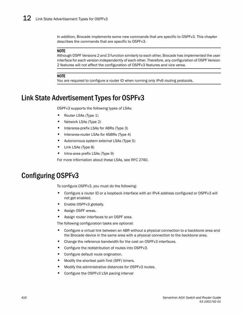
Link State Advertisement Types for OSPFv312DRAFT: BROCADE CONFIDENTIAL
In addition, Brocade implements some new commands that are specific to OSPFv3. This chapter describes the commands that are specific to OSPFv3.
NOTEAlthough OSPF Versions 2 and 3 function similarly to each other, Brocade has implemented the user interface for each version independently of each other. Therefore, any configuration of OSPF Version 2 features will not affect the configuration of OSPFv3 features and vice versa.
NOTEYou are required to configure a router ID when running only IPv6 routing protocols.
Link State Advertisement Types for OSPFv3OSPFv3 supports the following types of LSAs:
• Router LSAs (Type 1)
• Network LSAs (Type 2)
• Interarea-prefix LSAs for ABRs (Type 3)
• Interarea-router LSAs for ASBRs (Type 4)
• Autonomous system external LSAs (Type 5)
• Link LSAs (Type 8)
• Intra-area prefix LSAs (Type 9)
For more information about these LSAs, see RFC 2740.
Configuring OSPFv3To configure OSPFv3, you must do the following:
• Configure a router ID or a loopback interface with an IPv4 address configured or OSPFv3 will not get enabled.
• Enable OSPFv3 globally.
• Assign OSPF areas.
• Assign router interfaces to an OSPF area.
The following configuration tasks are optional:
• Configure a virtual link between an ABR without a physical connection to a backbone area and the Brocade device in the same area with a physical connection to the backbone area.
• Change the reference bandwidth for the cost on OSPFv3 interfaces.
• Configure the redistribution of routes into OSPFv3.
• Configure default route origination.
• Modify the shortest path first (SPF) timers.
• Modify the administrative distances for OSPFv3 routes.
• Configure the OSPFv3 LSA pacing interval
416 ServerIron ADX Switch and Router Guide53-1001742-01

Enabling OSPFv3 12DRAFT: BROCADE CONFIDENTIAL
• Modify how often the Brocade device checks on the elimination of the database overflow condition.
• Modify the external link state database limit.
• Modify the default values of OSPFv3 parameters for router interfaces.
• Disable or re-enable OSPFv3 event logging.
Enabling OSPFv3Before enabling the Brocade device to run OSPFv3, you must do the following:
• Enable the forwarding of IPv6 traffic on the Brocade device using the ipv6 unicast-routing command.
• Enable IPv6 on each interface over which you plan to enable OSPFv3. You enable IPv6 on an interface by configuring an IPv6 address or explicitly enabling IPv6 on that interface.
• Make sure one of the following is configured:
• A router ID using the ip router-id command.
• A loopback interface. If a loopback interface with an IPv6 address does not exist, any interface with an IP address, starting with the lowest IP address and moving to the highest IP address, will serve as the router ID.
By default, OSPFv3 is disabled. To enable OSPFv3, you must enable it globally.
To enable OSPFv3 globally, enter the following command:
ServerIron(config-ospf-router)# ipv6 router ospfServerIron(config-ospf6-router)#
After you enter this command, the Brocade device enters the IPv6 OSPF configuration level, where you can access several commands that allow you to configure OSPFv3.
Syntax: [no] ipv6 router ospf
To disable OSPFv3, enter the no form of this command. If you disable OSPFv3, the Brocade device removes all the configuration information for the disabled protocol from the running-config. Moreover, when you save the configuration to the startup-config file after disabling one of these protocols, all the configuration information for the disabled protocol is removed from the startup-config file.
The CLI displays a warning message such as the following:
ServerIron(config-ospf6-router)# no ipv6 router ospfipv6 router ospf mode now disabled. All ospf config data will be lost when writing to flash!
If you have disabled the protocol but have not yet saved the configuration to the startup-config file and reloaded the software, you can restore the configuration information by re-entering the command to enable the protocol (for example, ipv6 router ospf). If you have already saved the configuration to the startup-config file and reloaded the software, the information is gone. If you are testing an OSPF configuration and are likely to disable and re-enable the protocol, you might want to make a backup copy of the startup-config file containing the protocol’s configuration information. This way, if you remove the configuration information by saving the configuration after disabling the protocol, you can restore the configuration by copying the backup copy of the startup-config file onto the flash memory.
ServerIron ADX Switch and Router Guide 41753-1001742-01
Enabling OSPFv312DRAFT: BROCADE CONFIDENTIAL
Assigning OSPFv3 AreasAfter OSPFv3 is enabled, you can assign OSPFv3 areas. You can assign an IPv4 address or a number as the area ID for each area. The area ID is representative of all IPv6 addresses (subnets) on a router interface. Each router interface can support one area.
An area can be normal or a stub.
• Normal – OSPF routers within a normal area can send and receive External Link State Advertisements (LSAs).
• Stub – OSPF routers within a stub area cannot send or receive External LSAs. In addition, OSPF routers in a stub area must use a default route to the area’s Area Border Router (ABR) or Autonomous System Boundary Router (ASBR) to send traffic out of the area.
For example, to set up OSPFv3 areas 0.0.0.0, 200.5.0.0, 192.5.1.0, and 195.5.0.0, enter the following commands:
ServerIron(config-ospf6-router)# area 0.0.0.0ServerIron(config-ospf6-router)# area 200.5.0.0ServerIron(config-ospf6-router)# area 192.5.1.0ServerIron(config-ospf6-router)# area 195.5.0.0
Syntax: [no] area <number> | <ipv4-address>
The <number> | <ipv4-address> parameter specifies the area number, which can be a number or in IPv4 address format. If you specify a number, the number can be from 0 – 2,147,483,647.
NOTEYou can assign one area on a router interface.
Assigning a Totally Stubby Area
By default, the Brocade device sends summary LSAs (LSA type 3) into stub areas. You can further reduce the number of LSAs sent into a stub area by configuring the Brocade device to stop sending summary LSAs into the area. You can disable the summary LSAs when you are configuring the stub area or later after you have configured the area.
This feature disables origination of summary LSAs into a stub area, but the Brocade device still accepts summary LSAs from OSPF neighbors and floods them to other areas. The Brocade device can form adjacencies with other routers regardless of whether summarization is enabled or disabled for areas on each router.
When you disable the summary LSAs, the change takes effect immediately. If you apply the option to a previously configured area, the router flushes all of the summary LSAs it has generated (as an ABR) from the area.
NOTEThis feature applies only when the Brocade device is configured as an Area Border Router (ABR) for the area. To completely prevent summary LSAs from being sent to the area, disable the summary LSAs on each OSPF router that is an ABR for the area.
For example, to disable summary LSAs for stub area 40 and specify an additional metric of 99, enter the following command:
ServerIron(config-ospf6-router)#area 40 stub 99 no-summary
Syntax: area <number> | <ipv4-address> stub <metric> [no-summary]
418 ServerIron ADX Switch and Router Guide53-1001742-01

Enabling OSPFv3 12DRAFT: BROCADE CONFIDENTIAL
The <number> | <ipv4-address> parameter specifies the area number, which can be a number or in IPv4 address format. If you specify a number, the number can be from 0 – 2,147,483,647.
The stub <metric> parameter specifies an additional cost for using a route to or from this area and can be from 1 – 16777215. There is no default. Normal areas do not use the cost parameter.
The no-summary parameter applies only to stub areas and disables summary LSAs from being sent into the area.
Assigning Interfaces to an AreaAfter you define OSPFv3 areas, you must assign router interfaces to the areas. All router interfaces must be assigned to one of the defined areas on an OSPF router. When an interface is assigned to an area, all corresponding subnets on that interface are automatically included in the assignment.
For example, to assign Ethernet interface 3/1 to area 192.5.0.0, enter the following commands:
ServerIron(config)#interface ethernet 3/1ServerIron(config-if-e100-3/1)#ipv6 ospf area 192.5.0.0
Syntax: [no] ipv6 ospf area <number> | <ipv4-address>
The <number> | <ipv4-address> parameter specifies the area number, which can be a number or in IPv4 address format. If you specify a number, the number can be from 0 – 2,147,483,647.
To remove the interface from the specified area, use the no form of this command.
Configuring Virtual LinksAll ABRs must have either a direct or indirect link to an OSPF backbone area (0.0.0.0 or 0). If an ABR does not have a physical link to a backbone area, you can configure a virtual link from the ABR to another router within the same area that has a physical connection to the backbone area.
The path for a virtual link is through an area shared by the neighbor ABR (router with a physical backbone connection) and the ABR requiring a logical connection to the backbone.
Two parameters must be defined for all virtual links—transit area ID and neighbor router.
• The transit area ID represents the shared area of the two ABRs and serves as the connection point between the two routers. This number should match the area ID value.
• When assigned from the router interface requiring a logical connection, the neighbor router field is the router ID (IPv4 address) of the router that is physically connected to the backbone. When assigned from the router interface with the physical connection, the neighbor router is the router ID (IPv4) address of the router requiring a logical connection to the backbone.
NOTEBy default, the Brocade router ID is the IPv4 address configured on the lowest numbered loopback interface. If the Brocade device does not have a loopback interface, the default router ID is the lowest numbered IPv4 address configured on the device.
NOTEWhen you establish an area virtual link, you must configure it on both of the routers (both ends of the virtual link).
ServerIron ADX Switch and Router Guide 41953-1001742-01

Enabling OSPFv312DRAFT: BROCADE CONFIDENTIAL
For example, imagine that ABR1 in areas 1 and 2 is cut off from the backbone area (area 0). To provide backbone access to ABR1, you can add a virtual link between ABR1 and ABR2 in area 1 using area 1 as a transit area. To configure the virtual link, you define the link on the router that is at each end of the link. No configuration for the virtual link is required on the routers in the transit area.
To define the virtual link on ABR1, enter the following command on ABR1:
ServerIron(config-ospf6-router)#area 1 virtual-link 209.157.22.1
To define the virtual link on ABR2, enter the following command on ABR2:
ServerIron(config-ospf6-router)# area 1 virtual-link 10.0.0.1
Syntax: area <number> | <ipv4-address> virtual-link <router-id>
The area <number> | <ipv4-address> parameter specifies the transit area.
The <router-id> parameter specifies the router ID of the OSPF router at the remote end of the virtual link. To display the router ID on a router, enter the show ip command.
Assigning a Virtual Link Source Address
When routers at both ends of a virtual link need to communicate with one another, the source address included in the packets must be a global IPv6 address. Therefore, you must determine the global IPv6 address to be used by the routers for communication across the virtual link. You can specify that a router uses the IPv6 global address assigned to one of its interfaces.
For example, to specify the global IPv6 address assigned to Ethernet interface 3/1 on ABR1 as the source address for the virtual link on ABR1, enter the following command on ABR1:
ServerIron(config-ospf6-router)#virtual-link-if-address interface ethernet 3/1
To specify the global IPv6 address assigned to tunnel interface 1 on ABR2 as the source address for the virtual link on ABR2, enter the following command on ABR2:
ServerIron(config-ospf6-router)# virtual-link-if-address interface tunnel 1
Syntax: virtual-link-if-address interface ethernet <port> | loopback <number> | tunnel <number> | ve <number>
The ethernet | loopback | tunnel | ve parameter specifies the interface from which the router derives the source IPv6 address for communication across the virtual link. If you specify an Ethernet interface, also specify the port number associated with the interface. If you specify a loopback, tunnel, or VE interface, also specify the number associated with the respective interface.
To delete the source address for the virtual link, use the no form of this command.
Modifying Virtual Link Parameters
You can modify the following virtual link parameters:
• Dead-interval: The number of seconds that a neighbor router waits for a hello packet from the current router before declaring the router is down. The range is 1 – 65535 seconds. The default is 40 seconds.
• Hello-interval: The length of time between the transmission of hello packets. The range is 1 – 65535 seconds. The default is 10 seconds.
420 ServerIron ADX Switch and Router Guide53-1001742-01

Enabling OSPFv3 12DRAFT: BROCADE CONFIDENTIAL
• Retransmit-interval: The interval between the re-transmission of link state advertisements to router adjacencies for this interface. The range is 0 – 3600 seconds. The default is 5 seconds.
• Transmit-delay: The period of time it takes to transmit Link State Update packets on the interface. The range is 0 – 3600 seconds. The default is 1 second.
NOTEThe values of the dead-interval and hello-interval parameters must be the same at both ends of a virtual link. Therefore, if you modify the values of these parameters at one end of a virtual link, you must remember to make the same modifications on the other end of the link.
The values of the other virtual link parameters do not require synchronization.
For example, to change the dead interval to 60 seconds on the virtual links defined on ABR1 and ABR2, enter the following command on ABR1:
ServerIron(config-ospf6-router)# area 1 virtual-link 209.157.22.1 dead-interval 60
Enter the following command on ABR2:
ServerIron(config-ospf6-router)# area 1 virtual-link 10.0.0.1 dead-interval 60
Syntax: area <number> | <ipv4-address> virtual-link <router-id> [dead-interval <seconds> | hello-interval <seconds> | retransmit-interval <seconds> | transmit-delay <seconds>]
The area <number> | <ipv4-address> parameter specifies the transit area.
The <router-id> parameter specifies the router ID of the OSPF router at the remote end of the virtual link. To display the router ID on a router, enter the show ip command.
The dead-interval, hello-interval, retransmit-interval, and transmit-delay parameters are discussed earlier in this section.
Changing the Reference Bandwidth for the Cost on OSPFv3 InterfacesEach interface on which OSPFv3 is enabled has a cost associated with it. The Brocade device advertises its interfaces and their costs to OSPFv3 neighbors. For example, if an interface has an OSPF cost of ten, the Brocade device advertises the interface with a cost of ten to other OSPF routers.
By default, an interface’s OSPF cost is based on the port speed of the interface. The software uses the following formula to calculate the cost:
Cost = reference-bandwidth/interface-speed
By default, the reference bandwidth is 100 Mbps. If the resulting cost is less than 1, the software rounds the cost up to 1. The default reference bandwidth results in the following costs:
• 10 Mbps port’s cost = 100/10 = 10
• 100 Mbps port’s cost = 100/100 = 1
• 1000 Mbps port’s cost = 100/1000 = 0.10, which is rounded up to 1
• 155 Mbps port’s cost = 100/155 = 0.65, which is rounded up to 1
• 622 Mbps port’s cost = 100/622 = 0.16, which is rounded up to 1
• 2488 Mbps port’s cost = 100/2488 = 0.04, which is rounded up to 1
The bandwidth for interfaces that consist of more than one physical port is calculated as follows:
ServerIron ADX Switch and Router Guide 42153-1001742-01

Enabling OSPFv312DRAFT: BROCADE CONFIDENTIAL
• Trunk group – The combined bandwidth of all the ports.
• Virtual (Ethernet) interface – The combined bandwidth of all the ports in the port-based VLAN that contains the virtual interface.
You can change the default reference bandwidth from 100 Mbps to a value from 1 – 4294967 Mbps.
If a change to the reference bandwidth results in a cost change to an interface, the Brocade device sends a link state update to update the costs of interfaces advertised by the Brocade device.
NOTEIf you specify the cost for an individual interface, the cost you specify overrides the cost calculated by the software.
Some interface types are not affected by the reference bandwidth and always have the same cost regardless of the reference bandwidth in use:
• The cost of a loopback interface is always 0.
• The cost of a virtual link is calculated using the Shortest Path First (SPF) algorithm and is not affected by the auto-cost feature.
For example, to change the reference bandwidth to 500, enter the following command:
ServerIron(config-ospf6-router)# auto-cost reference-bandwidth 500
The reference bandwidth specified in this example results in the following costs:
• 10 Mbps port’s cost = 500/10 = 50
• 100 Mbps port’s cost = 500/100 = 5
• 1000 Mbps port’s cost = 500/1000 = 0.5, which is rounded up to 1
• 155 Mbps port’s cost = 500/155 = 3.23, which is rounded up to 4
• 622 Mbps port’s cost = 500/622 = 0.80, which is rounded up to 1
• 2488 Mbps port’s cost = 500/2488 = 0.20, which is rounded up to 1
The costs for 10 Mbps, 100 Mbps, and 155 Mbps ports change as a result of the changed reference bandwidth. Costs for higher-speed interfaces remain the same.
Syntax: [no] auto-cost reference-bandwidth <number>
The <number> parameter specifies the reference bandwidth and can be a value from 1 – 4294967. The default is 100.
To restore the reference bandwidth to its default value and thus restore the default costs of interfaces to their default values, enter the no form of this command.
Redistributing Routes into OSPFv3In addition to specifying which routes are redistributed into OSPFv3, you can configure the following aspects related to route redistribution:
• Default metric
• Metric type
• Advertisement of an external aggregate route
422 ServerIron ADX Switch and Router Guide53-1001742-01

Enabling OSPFv3 12DRAFT: BROCADE CONFIDENTIAL
Configuring Route Redistribution into OSPFv3
You can configure the Brocade device to redistribute routes from the following sources into OSPFv3:
• IPv6 static routes
• Directly connected IPv6 networks
You can redistribute routes in the following ways:
• By route types, for example, the Brocade device redistributes all IPv6 static routes.
• By using a route map to filter which routes to redistribute, for example, the Brocade device redistributes specified IPv6 static routes only.
For example, to configure the redistribution of all IPv6 static routes, enter the following commands:
ServerIron(config-ospf6-router)# redistribute static Syntax: [no] redistribute connected | static [metric <number> | metric-type <type>]
The connected | static keywords specify the route source.
The metric <number> parameter specifies the metric used for the redistributed route. If a value is not specified for this option, and the value for the default-metric command is set to 0, its default metric, then routes redistributed from the various routing protocols will have the metric value of the protocol from which they are redistributed. For information about the default-metric command, see “Modifying Default Metric for Routes Redistributed into OSPF Version 3” on page 424
The metric-type <type> parameter specifies an OSPF metric type for the redistributed route. You can specify external type 1 or external type 2. If a value is not specified for this option, the Brocade device uses the value specified by the metric-type command. For information about modifying the default metric type using the metric-type command, see “Modifying Default Metric for Routes Redistributed into OSPF Version 3” on page 424
For example, to configure a route map and use it for redistribution of routes into OSPFv3, enter commands such as the following:
ServerIron(config)# ipv6 route 2001:1::/32 4823:eoff:343e::23ServerIron(config)# ipv6 route 2001:2::/32 4823:eoff:343e::23ServerIron(config)# ipv6 route 2001:3::/32 4823:eoff:343e::23 metric 5ServerIron(config)# route-map abc permit 1ServerIron(config-routemap-abc)# match metric 5ServerIron(config-routemap-abc)# set metric 8ServerIron(config-routemap-abc)# ipv6 router ospfServerIron(config-ospf6-router)#r edistribute static route-map abc
The commands in this example configure some static IPv6 routes and a route map, and use the route map for redistributing the static IPv6 routes into OSPFv3.
The ipv6 route commands configure the static IPv6 routes.
The route-map command begins configuration of a route map called “abc”. The number indicates the route map entry (called the “instance”) you are configuring. A route map can contain multiple entries. The software compares packets to the route map entries in ascending numerical order and stops the comparison once a match is found.
The match command in the route map matches on routes that have 5 for their metric value (cost). The set command changes the metric in routes that match the route map to 8.
ServerIron ADX Switch and Router Guide 42353-1001742-01
Enabling OSPFv312DRAFT: BROCADE CONFIDENTIAL
The redistribute command configures the redistribution of static IPv6 routes into OSPFv3, and uses route map “abc“ to control the routes that are redistributed. In this example, the route map allows a static IPv6 route to be redistributed into OSPF only if the route has a metric of 5, and changes the metric to 8 before placing the route into the OSPF route redistribution table.
Syntax: [no] redistribute connected | static [route-map <map-name>]
The connected | static keywords specify the route source.
The route-map <map-name> parameter specifies the route map name. The following match parameters are valid for OSPFv3 redistribution:
• match metric <number>
The following set parameters are valid for OSPF redistribution:
• set metric [+ | - ] <number> | none
• set metric-type type-1 | type-2
NOTEYou must configure the route map before you configure a redistribution filter that uses the route map.
NOTEWhen you use a route map for route redistribution, the software disregards the permit or deny action of the route map.
NOTEFor an external route that is redistributed into OSPFv3 through a route map, the metric value of the route remains the same unless the metric is set by a set metric command inside the route map or the default-metric <num> command. For a route redistributed without using a route map, the metric is set by the metric parameter if set or the default-metric <num> command if the metric parameter is not set.
Modifying Default Metric for Routes Redistributed into OSPF Version 3
The default metric is a global parameter that specifies the cost applied by default to routes redistributed into OSPFv3. The default value is 0.
If the metric parameter for the redistribute command is not set and the default-metric command is set to 0, its default value, then routes redistributed from the various routing protocols will have the metric value of the protocol from which they are redistributed. For information about the redistribute command, see “Configuring Route Redistribution into OSPFv3” on page 423.
NOTEYou also can define the cost on individual interfaces. The interface cost overrides the default cost. For information about defining the cost on individual interfaces, see “Modifying OSPFv3 Interface Defaults” on page 431 and “Changing the Reference Bandwidth for the Cost on OSPFv3 Interfaces” on page 421.
To assign a default metric of 4 to all routes imported into OSPFv3, enter the following command:
ServerIron(config-ospf6-router)# default-metric 4
Syntax: [no] default-metric <number>
424 ServerIron ADX Switch and Router Guide53-1001742-01

Enabling OSPFv3 12DRAFT: BROCADE CONFIDENTIAL
You can specify a value from 0 – 65535. The default is 0.
To restore the default metric to the default value, use the no form of this command.
Modifying Metric Type for Routes Redistributed into OSPF Version 3The Brocade device uses the metric-type parameter by default for all routes redistributed into OSPFv3 unless you specify a different metric type for individual routes using the redistribute command. (For more information about using the redistribute command, see “Redistributing Routes into OSPFv3” on page 422).
A type 1 route specifies a small metric (two bytes), while a type 2 route specifies a big metric (three bytes). The default value is type 2.
To modify the default value of type 2 to type 1, enter the following command:
ServerIron(config-ospf6-router)#metric-type type1
Syntax: [no] metric-type type1 | type2
To restore the metric type to the default value, use the no form of this command.
Configuring External Route SummarizationWhen the Brocade device is an OSPF Autonomous System Boundary Router (ASBR), you can configure it to advertise one external route as an aggregate for all redistributed routes that are covered by a specified IPv6 address range.
When you configure an address range, the range takes effect immediately. All the imported routes are summarized according to the configured address range. Imported routes that have already been advertised and that fall within the range are flushed out of the AS and a single route corresponding to the range is advertised.
If a route that falls within a configured address range is imported by the Brocade device, no action is taken if the device has already advertised the aggregate route; otherwise, the device advertises the aggregate route. If an imported route that falls within a configured address range is removed by the device, no action is taken if there are other imported route(s) that fall with in the same address range; otherwise the aggregate route is flushed.
You can configure up to 32 address ranges. The Brocade device sets the forwarding address of the aggregate route to zero and sets the tag to zero.
If you delete an address range, the advertised aggregate route is flushed and all imported routes that fall within the range are advertised individually.
If an external link state database overflow (LSDB) condition occurs, all aggregate routes are flushed out of the AS, along with other external routes. When the Brocade device exits the external LSDB overflow condition, all the imported routes are summarized according to the configured address ranges.
NOTE: If you use redistribution filters in addition to address ranges, the Brocade device applies the redistribution filters to routes first, then applies them to the address ranges.
NOTE: If you disable redistribution, all the aggregate routes are flushed, along with other imported routes.
NOTE: This option affects only imported, type 5 external routes. A single type 5 LSA is generated and flooded throughout the AS for multiple external routes.
To configure the summary address 2201::/24 for routes redistributed into OSPFv3, enter the following command:
ServerIron(config-ospf6-router)#summary-address 2201::/24
ServerIron ADX Switch and Router Guide 42553-1001742-01

Enabling OSPFv312DRAFT: BROCADE CONFIDENTIAL
In this example, the summary prefix 2201::/24 includes addresses 2201::/1 through 2201::/24. Only the address FEC0::/24 is advertised in an external link-state advertisement.
Syntax: summary-address <ipv6-prefix>/<prefix-length>
You must specify the <ipv6-prefix> parameter in hexadecimal using 16-bit values between colons as documented in RFC 2373.
You must specify the <prefix-length> parameter as a decimal value. A slash mark (/) must follow the <ipv6-prefix> parameter and precede the <prefix-length> parameter.
Filtering OSPFv3 RoutesYou can filter the routes to be placed in the OSPFv3 route table by configuring distribution lists. OSPFv3 distribution lists can be applied globally or to an interface.
The functionality of OSPFv3 distribution lists is similar to that of OSPFv2 distribution lists. However, unlike OSPFv2 distribution lists, which filter routes based on criteria specified in an Access Control List (ACL), OSPFv3 distribution lists can filter routes using information specified in an IPv6 prefix list or a route map.
Configuration Examples
The following sections show examples of filtering OSPFv3 routes using prefix lists globally and for a specific interface, as well as filtering OSPFv3 routes using a route map.
You can configure the device to use all three types of filtering. When you do this, filtering using route maps has higher priority over filtering using global prefix lists. Filtering using prefix lists for a specific interface has lower priority than the other two filtering methods.
The example in this section assume the following routes are in the OSPFv3 route table:
Configuring an OSPFv3 Distribution List Using a Route Map as Input
The following commands configure a route map that matches internal routes:
ServerIron(config)# route-map allowInternalRoutes permit 10ServerIron(config-routemap allowInternalRoutes)# match route-type internal
See “Policy-Based Routing” for information on configuring route maps.
ServerIron#show ipv6 ospf route
Current Route count: 5 Intra: 3 Inter: 0 External: 2 (Type1 0/Type2 2) Equal-cost multi-path: 0 Destination Options Area Cost Type2 Cost Next Hop Router Outgoing Interface*IA 3001::/64 --------- 0.0.0.1 0 0 :: ve 10*E2 3010::/64 --------- 0.0.0.0 10 0 fe80::2e0:52ff:fe00:10 ve 10*IA 3015::/64 V6E---R-- 0.0.0.0 11 0 fe80::2e0:52ff:fe00:10 ve 10*IA 3020::/64 --------- 0.0.0.0 10 0 :: ve 11*E2 6001:5000::/64 --------- 0.0.0.0 10 0 fe80::2e0:52ff:fe00:10 ve 10
426 ServerIron ADX Switch and Router Guide53-1001742-01
Enabling OSPFv3 12DRAFT: BROCADE CONFIDENTIAL
The following commands configure a distribution list that applies the allowInternalRoutes route map globally to OSPFv3 routes:
ServerIron(config)# ipv6 router ospfServerIron(config-ospf6-router)# distribute-list route-map allowinternalroutes in
Syntax: [no] distribute-list route-map <name> in
After this distribution list is configured, the internal routes would be included, and the external routes would be omitted from the OSPFv3 route table:
Configuring Default Route OriginationWhen the Brocade device is an OSPF Autonomous System Boundary Router (ASBR), you can configure it to automatically generate a default external route into an OSPFv3 routing domain. This feature is called “default route origination” or “default information origination.”
By default, the Brocade device does not advertise the default route into the OSPFv3 domain. If you want the device to advertise the OSPF default route, you must explicitly enable default route origination.
When you enable OSPF default route origination, the device advertises a type 5 default route that is flooded throughout the AS (except stub areas).
The device advertises the default route into OSPF even if OSPF route redistribution is not enabled.
NOTEThe Brocade device does not advertise the OSPF default route, regardless of other configuration parameters, unless you explicitly enable default route origination.
If default route origination is enabled and you disable it, the default route originated by the device is flushed. Default routes generated by other OSPF routers are not affected. If you re-enable the feature, the feature takes effect immediately and thus does not require you to reload the software.
For example, to create and advertise a default route with a metric of 2 and as a type 1 external route, enter the following command:
ServerIron(config-ospf6-router)#default-information-originate always metric 2 metric-type type1
Syntax: [no] default-information-originate [always] [metric <value>] [metric-type <type>]
The always keyword originates a default route regardless of whether the device has learned a default route. This option is disabled by default.
ServerIron# show ipv6 ospf route
Current Route count: 3 Intra: 3 Inter: 0 External: 0 (Type1 0/Type2 0) Equal-cost multi-path: 0 Destination Options Area Cost Type2 Cost Next Hop Router Outgoing Interface*IA 3001::/64 --------- 0.0.0.1 0 0 :: ve 10*IA 3015::/64 V6E---R-- 0.0.0.0 11 0 fe80::2e0:52ff:fe00:10 ve 10*IA 3020::/64 --------- 0.0.0.0 10 0 :: ve 11
ServerIron ADX Switch and Router Guide 42753-1001742-01
Enabling OSPFv312DRAFT: BROCADE CONFIDENTIAL
The metric <value> parameter specifies a metric for the default route. If this option is not used, the value of the default-metric command is used for the route. For information about this command, see “Modifying Default Metric for Routes Redistributed into OSPF Version 3” on page 424
The metric-type <type> parameter specifies the external link type associated with the default route advertised into the OSPF routing domain. The <type> can be one of the following:
• 1 – Type 1 external route
• 2 – Type 2 external route
If you do not use this option, the default redistribution metric type is used for the route type.
NOTEIf you specify a metric and metric type, the values you specify are used even if you do not use the always option.
To disable default route origination, enter the no form of the command.
Modifying Shortest Path First TimersThe Brocade device uses the following timers when calculating the shortest path for OSPFv3 routes:
• SPF delay – When the Brocade device receives a topology change, the software waits before it starts a Shortest Path First (SPF) calculation. By default, the software waits 5 seconds. You can configure the SPF delay to a value from 0 – 65535 seconds. If you set the SPF delay to 0 seconds, the software immediately begins the SPF calculation after receiving a topology change.
• SPF hold time – The Brocade device waits a specific amount of time between consecutive SPF calculations. By default, the device waits 10 seconds. You can configure the SPF hold time to a value from 0 – 65535 seconds. If you set the SPF hold time to 0 seconds, the software does not wait between consecutive SPF calculations.
You can set the SPF delay and hold time to lower values to cause the device to change to alternate paths more quickly if a route fails. Note that lower values for these parameters require more CPU processing time.
You can change one or both of the timers.
NOTEIf you want to change only one of the timers, for example, the SPF delay timer, you must specify the new value for this timer as well as the current value of the SPF hold timer, which you want to retain. The Brocade device does not accept only one timer value.
To change the SPF delay to 10 seconds and the SPF hold to 20 seconds, enter the following command:
ServerIron(config-ospf6-router)#timers spf 10 20
Syntax: timers spf <delay> <hold-time>
For the <delay> and <hold-time> parameters, specify a value from 0 – 65535 seconds.
To set the timers back to their default values, enter the no version of this command.
428 ServerIron ADX Switch and Router Guide53-1001742-01

Enabling OSPFv3 12DRAFT: BROCADE CONFIDENTIAL
Modifying Administrative DistanceThe Brocade device can learn about networks from various protocols, including IPv6, RIPng, and OSPFv3. Consequently, the routes to a network may differ depending on the protocol from which the routes were learned. By default, the administrative distance for OSPFv3 routes is 110.
The device selects one route over another based on the source of the route information. To do so, the device can use the administrative distances assigned to the sources. You can influence the device’s decision by changing the default administrative distance for OSPFv3 routes.
Configuring Administrative Distance Based on Route Type
You can configure a unique administrative distance for each type of OSPFv3 route. For example, you can use this feature to influence the Brocade device to prefer a static route over an OSPF inter-area route and to prefer OSPF intra-area routes to static routes.
The distance you specify influences the choice of routes when the device has multiple routes to the same network from different protocols. The device prefers the route with the lower administrative distance.
You can specify unique default administrative distances for the following OSPFv3 route types:
• Intra-area routes
• Inter-area routes
• External routes
The default for all of these OSPFv3 route types is 110.
NOTEThis feature does not influence the choice of routes within OSPFv3. For example, an OSPF intra-area route is always preferred over an OSPF inter-area route, even if the intra-area route’s distance is greater than the inter-area route’s distance.
For example, to change the default administrative distances for intra-area routes to 80, inter-area routes to 90, and external routes to 100, enter the following commands:
ServerIron(config-ospf6-router)#distance intra-area 80ServerIron(config-ospf6-router)#distance inter-area 90ServerIron(config-ospf6-router)#distance external 100
Syntax: distance external | inter-area | intra-area <distance>
The external | inter-area | intra-area keywords specify the route type for which you are changing the default administrative distance.
The <distance> parameter specifies the new distance for the specified route type. You can specify a value from 1 – 255.
To reset the administrative distance of a route type to its system default, enter the no form of this command.
ServerIron ADX Switch and Router Guide 42953-1001742-01

Enabling OSPFv312DRAFT: BROCADE CONFIDENTIAL
Configuring the OSPFv3 LSA Pacing IntervalThe Brocade device paces OSPFv3 LSA refreshes by delaying the refreshes for a specified time interval instead of performing a refresh each time an individual LSA’s refresh timer expires. The accumulated LSAs constitute a group, which the Brocade device refreshes and sends out together in one or more packets.
The pacing interval, which is the interval at which the Brocade device refreshes an accumulated group of LSAs, is configurable to a range from 10 – 1800 seconds (30 minutes). The default is 240 seconds (four minutes). Thus, every four minutes, the Brocade device refreshes the group of accumulated LSAs and sends the group together in the same packet(s).
The pacing interval is inversely proportional to the number of LSAs the Brocade device is refreshing and aging. For example, if you have approximately 10,000 LSAs, decreasing the pacing interval enhances performance. If you have a very small database (40 – 100 LSAs), increasing the pacing interval to 10 – 20 minutes might enhance performance only slightly.
To change the OSPFv3 LSA pacing interval to two minutes (120 seconds), enter the following command:
ServerIron(config)# ipv6 router ospfServerIron(config-ospf6-router)# timers lsa-group-pacing 120
Syntax: [no] timers lsa-group-pacing <seconds>
The <seconds> parameter specifies the number of seconds and can be from 10 – 1800 (30 minutes). The default is 240 seconds (four minutes).
To restore the pacing interval to its default value, use the no form of the command.
Modifying Exit Overflow IntervalIf a database overflow condition occurs on the Brocade device, the device eliminates the condition by removing entries that originated on the device. The exit overflow interval allows you to set how often a device checks to see if the overflow condition has been eliminated. The default value is 0. If the configured value of the database overflow interval is 0, then the device never leaves the database overflow condition.
For example, to modify the exit overflow interval to 60 seconds, enter the following command:
ServerIron(config-ospf6-router)# database-overflow-interval 60
Syntax: [no] auto-cost reference-bandwidth <number>
The <seconds> parameter can be a value from 0 – 86400 seconds (24 hours).
To reset the exit overflow interval to its system default, enter the no form of this command.
Modifying External Link State Database LimitBy default, the link state database can hold a maximum of 2000 entries for external (type 5) LSAs. You can change the maximum number of entries from 500 – 8000. After changing this limit, make sure to save the running-config file and reload the software. The change does not take effect until you reload or reboot the software.
For example, to change the maximum number entries from the default of 2000 to 3000, enter the following command:
430 ServerIron ADX Switch and Router Guide53-1001742-01
Enabling OSPFv3 12DRAFT: BROCADE CONFIDENTIAL
ServerIron(config-ospf6-router)#e xternal-lsdb-limit 3000
Syntax: ipv6 ospf area <number> | <ipv4-address>
The <entries> parameter can be a numerical value from 500 – 8000 seconds.
To reset the maximum number of entries to its system default, enter the no form of this command.
Modifying OSPFv3 Interface DefaultsOSPFv3 has interface parameters that you can configure. For simplicity, each of these parameters has a default value. No change to these default values is required except as needed for specific network configurations.
You can modify the default values for the following OSPF interface parameters:
• Cost: Indicates the overhead required to send a packet across an interface. You can modify the cost to differentiate between 100 Mbps and 1000 Mbps (1 Gbps) links. The command syntax is ipv6 ospf cost <number>. The default cost is calculated by dividing 100 million by the bandwidth. For 10 Mbps links, the cost is 10. The cost for both 100 Mbps and 1000 Mbps links is 1, because the speed of 1000 Mbps was not in use at the time the OSPF cost formula was devised.
• Dead-interval: Indicates the number of seconds that a neighbor router waits for a hello packet from the current router before declaring the router down. The command syntax is ipv6 ospf dead-interval <seconds>. The value can be from 1 – 2147483647 seconds. The default is 40 seconds.
• Hello-interval: Represents the length of time between the transmission of hello packets. The command syntax is ipv6 ospf hello-interval <seconds>. The value can be from 1 – 65535 seconds. The default is 10 seconds.
• Instance: Indicates the number of OSPFv3 instances running on an interface. The command syntax is ipv6 ospf instance <number>. The value can be from 0 – 255. The default is 1.
• MTU-ignore: Allows you to disable a check that verifies the same MTU is used on an interface shared by neighbors. The command syntax is ipv6 ospf mtu-ignore. By default, the mismatch detection is enabled.
• Network: Allows you to configure the OSPF network type. The command syntax is ipv6 ospf network [point-to-multipoint]. The default setting of the parameter depends on the network type.
• Passive: When you configure an OSPF interface to be passive, that interface does not send or receive OSPF route updates. This option affects all IPv6 subnets configured on the interface. The command syntax is ipv6 ospf passive. By default, all OSPF interfaces are active and thus can send and receive OSPF route information. Since a passive interface does not send or receive route information, the interface is in effect a stub network.
• Priority: Allows you to modify the priority of an OSPF router. The priority is used when selecting the designated router (DR) and backup designated routers (BDRs). The command syntax is ipv6 ospf priority <number>. The value can be from 0 – 255. The default is 1. If you set the priority to 0, the router does not participate in DR and BDR election.
• Retransmit-interval: The time between retransmissions of LSAs to adjacent routers for an interface. The command syntax is ipv6 ospf retransmit-interval <seconds>. The value can be from 0 – 3600 seconds. The default is 5 seconds.
ServerIron ADX Switch and Router Guide 43153-1001742-01

Displaying OSPFv3 Information12DRAFT: BROCADE CONFIDENTIAL
• Transmit-delay: The time it takes to transmit Link State Update packets on this interface. The command syntax is ipv6 ospf transmit-delay <seconds>. The value can be from 0 – 3600 seconds. The default is 1 second.
Disabling or Re-enabling Event LoggingOSPFv3 does not currently support the generation of SNMP traps. Instead, you can disable or re-enable the logging of OSPFv3-related events such as neighbor state changes and database overflow conditions. By default, the Brocade device logs these events.
To disable the logging of events, enter the following command:
ServerIron(config-ospf6-router)# no log-status-change
Syntax: [no] log-status-change
To re-enable the logging of events, enter the following command:
ServerIron(config-ospf6-router)# log-status-change
Displaying OSPFv3 InformationYou can display the information for the following OSPFv3 parameters:
• Areas
• Link state databases
• Interfaces
• Memory usage
• Neighbors
• Redistributed routes
• Routes
• SPF
• Virtual links
• Virtual neighbors
Displaying OSPFv3 Area InformationTo display global OSPFv3 area information for the Brocade device, enter the following command at any CLI level:
ServerIron# show ipv6 ospf areaArea 0: Interface attached to this area: loopback 2 ethe 3/2 tunnel 2 Number of Area scoped LSAs is 6 Statistics of Area 0: SPF algorithm executed 16 times SPF last updated: 335256 sec ago Current SPF node count: 3 Router: 2 Network: 1 Maximum of Hop count to nodes: 2...
432 ServerIron ADX Switch and Router Guide53-1001742-01

Displaying OSPFv3 Information 12DRAFT: BROCADE CONFIDENTIAL
Syntax: show ipv6 ospf area [<area id>]
You can specify the <area-id> parameter in the following formats:
• As an IPv4 address, for example, 192.168.1.1.
• As a numerical value from 0 – 2,147,483,647.
The <area-id> parameter restricts the display to the specified OSPF area.
This display shows the following information:
Displaying OSPFv3 Database InformationYou can display a summary of the Brocade device’s link state database or detailed information about a specified LSA type.
To display a summary of a device’s link state database, enter the following command at any CLI level:
TABLE 60 OSPFv3 area information fields
This Field... Displays...
Area The area number.
Interface attached to this area The router interfaces attached to the area.
Number of Area scoped LSAs Number of LSAs with a scope of the specified area.
SPF algorithm executed The number of times the OSPF Shortest Path First (SPF) algorithm is executed within the area.
SPF last updated The interval in seconds that the SPF algorithm was last executed within the area.
Current SPF node count The current number of SPF nodes in the area.
Router Number of router LSAs in the area.
Network Number of network LSAs in the area.
Indx The row number of the entry in the router’s OSPF area table.
Area The area number.
Maximum hop count to nodes. The maximum number of hop counts to an SPF node within the area.
ServerIron#show ipv6 ospf databaseArea ID Type LS ID Adv Rtr Seq(Hex) Age Cksum Len0 Link 000001e6 223.223.223.223 800000ab 1547 8955 680 Link 000000d8 1.1.1.1 800000aa 1295 0639 680 Link 00000185 223.223.223.223 800000ab 1481 7e6b 560 Iap 00000077 223.223.223.223 800000aa 1404 966a 560 Rtr 00000124 223.223.223.223 800000b0 1397 912c 400 Net 00000016 223.223.223.223 800000aa 1388 1b09
ServerIron ADX Switch and Router Guide 43353-1001742-01
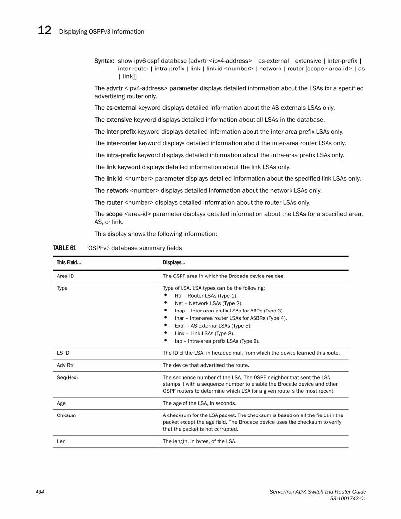
Displaying OSPFv3 Information12DRAFT: BROCADE CONFIDENTIAL
Syntax: show ipv6 ospf database [advrtr <ipv4-address> | as-external | extensive | inter-prefix | inter-router | intra-prefix | link | link-id <number> | network | router [scope <area-id> | as | link]]
The advrtr <ipv4-address> parameter displays detailed information about the LSAs for a specified advertising router only.
The as-external keyword displays detailed information about the AS externals LSAs only.
The extensive keyword displays detailed information about all LSAs in the database.
The inter-prefix keyword displays detailed information about the inter-area prefix LSAs only.
The inter-router keyword displays detailed information about the inter-area router LSAs only.
The intra-prefix keyword displays detailed information about the intra-area prefix LSAs only.
The link keyword displays detailed information about the link LSAs only.
The link-id <number> parameter displays detailed information about the specified link LSAs only.
The network <number> displays detailed information about the network LSAs only.
The router <number> displays detailed information about the router LSAs only.
The scope <area-id> parameter displays detailed information about the LSAs for a specified area, AS, or link.
This display shows the following information:
TABLE 61 OSPFv3 database summary fields
This Field... Displays...
Area ID The OSPF area in which the Brocade device resides.
Type Type of LSA. LSA types can be the following:• Rtr – Router LSAs (Type 1).• Net – Network LSAs (Type 2).• Inap – Inter-area prefix LSAs for ABRs (Type 3).• Inar – Inter-area router LSAs for ASBRs (Type 4).• Extn – AS external LSAs (Type 5).• Link – Link LSAs (Type 8).• Iap – Intra-area prefix LSAs (Type 9).
LS ID The ID of the LSA, in hexadecimal, from which the device learned this route.
Adv Rtr The device that advertised the route.
Seq(Hex) The sequence number of the LSA. The OSPF neighbor that sent the LSA stamps it with a sequence number to enable the Brocade device and other OSPF routers to determine which LSA for a given route is the most recent.
Age The age of the LSA, in seconds.
Chksum A checksum for the LSA packet. The checksum is based on all the fields in the packet except the age field. The Brocade device uses the checksum to verify that the packet is not corrupted.
Len The length, in bytes, of the LSA.
434 ServerIron ADX Switch and Router Guide53-1001742-01

Displaying OSPFv3 Information 12DRAFT: BROCADE CONFIDENTIAL
For example, to display detailed information about all LSAs in the database, enter the following command at any CLI level:
NOTEPortions of this display are truncated for brevity. The purpose of this display is to show all possible fields that might display rather than to show complete output.
ServerIron# show ipv6 ospf database extensiveArea ID Type LS ID Adv Rtr Seq(Hex) Age Cksum Len0 Link 00000031 1.1.1.1 80000001 35 6db9 56 Router Priority: 1 Options: V6E---R-- LinkLocal Address: fe80::1 Number of Prefix: 1 Prefix Options: Prefix: 3002::/64 ...Area ID Type LS ID Adv Rtr Seq(Hex) Age Cksum Len0 Iap 00000159 223.223.223.223 800000ab 357 946b 56 Number of Prefix: 2 Referenced LS Type: Network Referenced LS ID: 00000159 Referenced Advertising Router: 223.223.223.223 Prefix Options: Metric: 0 Prefix: 2000:4::/64 Prefix Options: Metric: 0 Prefix: 2002:c0a8:46a::/64Area ID Type LS ID Adv Rtr Seq(Hex) Age Cksum Len0 Rtr 00000039 223.223.223.223 800000b1 355 8f2d 40 Capability Bits: --E- Options: V6E---R-- Type: Transit Metric: 1 Interface ID: 00000058 Neighbor Interface ID: 00000058 Neighbor Router ID: 223.223.223.223Area ID Type LS ID Adv Rtr Seq(Hex) Age Cksum Len0 Net 000001f4 223.223.223.223 800000ab 346 190a 32 Options: V6E---R-- Attached Router: 223.223.223.223 Attached Router: 1.1.1.1...Area ID Type LS ID Adv Rtr Seq(Hex) Age Cksum LenN/A Extn 000001df 223.223.223.223 800000af 368 0aa8 32 Bits: E Metric: 00000001 Prefix Options: Referenced LSType: 0 Prefix: 2002::/16Area ID Type LS ID Adv Rtr Seq(Hex) Age Cksum Len1 Inap 0000011d 10.1.1.188 80000001 124 25de 36 Metric: 2 Prefix Options: Prefix: 2000:2:2::/64Area ID Type LS ID Adv Rtr Seq(Hex) Age Cksum Len0 Inar 0000005b 10.1.1.198 80000001 990 dbad 32 Options: V6E---R-- Metric: 1 Destination Router ID:10.1.1.188
ServerIron ADX Switch and Router Guide 43553-1001742-01

Displaying OSPFv3 Information12DRAFT: BROCADE CONFIDENTIAL
The fields that display depend upon the LSA type as shown in the following:
TABLE 62 OSPFv3 detailed database information fields
This Field... Displays...
Router LSA (Type 1) (Rtr) Fields
Capability Bits A bit that indicates the capability of the Brocade device. The bit can be set to one of the following:• B – The device is an area border router.• E – The device is an AS boundary router.• V – The device is a virtual link endpoint.• W – The device is a wildcard multicast receiver.
Options A 24-bit field that enables IPv6 OSPF routers to support the optional capabilities. When set, the following bits indicate the following:V6 – The device should be included in IPv6 routing calculations.E – The device floods AS-external-LSAs as described in RFC 2740.MC – The device forwards multicast packets as described in RFC 1586.N – The device handles type 7 LSAs as described in RFC 1584.R – The originator is an active router.DC –The device handles demand circuits.
Type The type of interface. Possible types can be the following:• Point-to-point – A point-to-point connection to another router.• Transit – A connection to a transit network.• Virtual link – A connection to a virtual link.
Metric The cost of using this router interface for outbound traffic.
Interface ID The ID assigned to the router interface.
Neighbor Interface ID The interface ID that the neighboring router has been advertising in hello packets sent on the attached link.
Neighbor Router ID The router ID (IPv4 address) of the neighboring router that advertised the route. (By default, the Brocade router ID is the IPv4 address configured on the lowest numbered loopback interface. If the Brocade device does not have a loopback interface, the default router ID is the lowest numbered IPv4 address configured on the device.)
436 ServerIron ADX Switch and Router Guide53-1001742-01
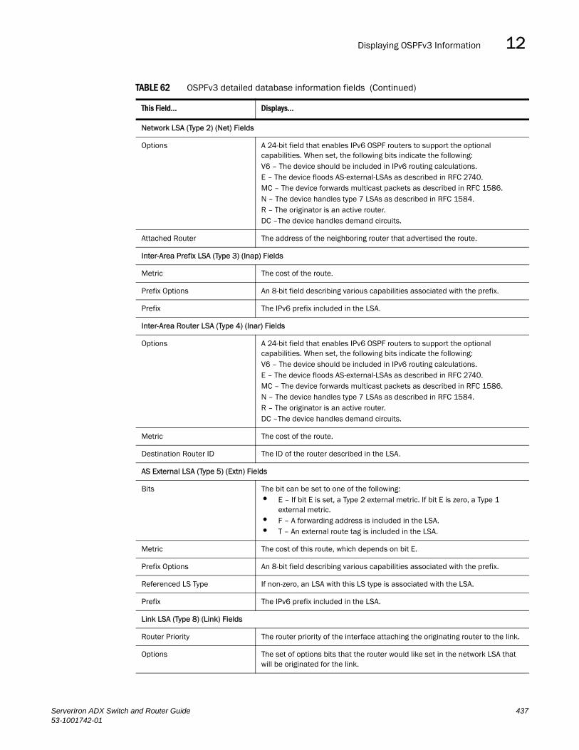
Displaying OSPFv3 Information 12DRAFT: BROCADE CONFIDENTIAL
Network LSA (Type 2) (Net) Fields
Options A 24-bit field that enables IPv6 OSPF routers to support the optional capabilities. When set, the following bits indicate the following:V6 – The device should be included in IPv6 routing calculations.E – The device floods AS-external-LSAs as described in RFC 2740.MC – The device forwards multicast packets as described in RFC 1586.N – The device handles type 7 LSAs as described in RFC 1584.R – The originator is an active router.DC –The device handles demand circuits.
Attached Router The address of the neighboring router that advertised the route.
Inter-Area Prefix LSA (Type 3) (Inap) Fields
Metric The cost of the route.
Prefix Options An 8-bit field describing various capabilities associated with the prefix.
Prefix The IPv6 prefix included in the LSA.
Inter-Area Router LSA (Type 4) (Inar) Fields
Options A 24-bit field that enables IPv6 OSPF routers to support the optional capabilities. When set, the following bits indicate the following:V6 – The device should be included in IPv6 routing calculations.E – The device floods AS-external-LSAs as described in RFC 2740.MC – The device forwards multicast packets as described in RFC 1586.N – The device handles type 7 LSAs as described in RFC 1584.R – The originator is an active router.DC –The device handles demand circuits.
Metric The cost of the route.
Destination Router ID The ID of the router described in the LSA.
AS External LSA (Type 5) (Extn) Fields
Bits The bit can be set to one of the following:• E – If bit E is set, a Type 2 external metric. If bit E is zero, a Type 1
external metric.• F – A forwarding address is included in the LSA.• T – An external route tag is included in the LSA.
Metric The cost of this route, which depends on bit E.
Prefix Options An 8-bit field describing various capabilities associated with the prefix.
Referenced LS Type If non-zero, an LSA with this LS type is associated with the LSA.
Prefix The IPv6 prefix included in the LSA.
Link LSA (Type 8) (Link) Fields
Router Priority The router priority of the interface attaching the originating router to the link.
Options The set of options bits that the router would like set in the network LSA that will be originated for the link.
TABLE 62 OSPFv3 detailed database information fields (Continued)
This Field... Displays...
ServerIron ADX Switch and Router Guide 43753-1001742-01

Displaying OSPFv3 Information12DRAFT: BROCADE CONFIDENTIAL
Displaying OSPFv3 Interface InformationYou can display a summary of information for all OSPFv3 interfaces or detailed information about a specified OSPFv3 interface.
To display a summary of OSPFv3 interfaces, enter the following command at any CLI level:
Syntax: show ipv6 ospf interface [ethernet <port> | loopback <number> | tunnel <number> | ve <number>]
The ethernet | loopback | tunnel | ve parameter specifies the interface for which to display information. If you specify an Ethernet interface, also specify the port number associated with the interface. If you specify a loopback, tunnel, or VE interface, also specify the number associated with the interface.
Link Local Address The originating router’s link-local interface address on the link.
Number of Prefix The number of IPv6 address prefixes contained in the LSA.
Prefix Options An 8-bit field of capabilities that serve as input to various routing calculations:• NU – The prefix is excluded from IPv6 unicast calculations.• LA – The prefix is an IPv6 interface address of the advertising router.• MC – The prefix is included in IPv6 multicast routing calculations
Prefix The IPv6 prefix included in the LSA.
Intra-Area Prefix LSAs (Type 9) (Iap) Fields
Number of Prefix The number of prefixes included in the LSA.
Referenced LS Type, Referenced LS ID
Identifies the router-LSA or network-LSA with which the IPv6 address prefixes are associated.
Referenced Advertising Router The address of the neighboring router that advertised the route.
Prefix Options An 8-bit field describing various capabilities associated with the prefix.
Metric The cost of using the advertised prefix.
Prefix The IPv6 prefix included in the LSA.
Number of Prefix The number of prefixes included in the LSA.
TABLE 62 OSPFv3 detailed database information fields (Continued)
This Field... Displays...
ServerIron# show ipv6 ospf interfaceInterface OSPF Status State Areaethe 3/1 upethe 3/2 enabled up DR 0ethe 3/4 disabled downloopback 2 enabled up Loopback 0tunnel 1 disabled downtunnel 2 enabled up P2P 0tunnel 6 up
438 ServerIron ADX Switch and Router Guide53-1001742-01

Displaying OSPFv3 Information 12DRAFT: BROCADE CONFIDENTIAL
This display shows the following information:
TABLE 63 Summary of OSPFv3 interface information
This Field... Displays...
Interface The interface type, and the port number or number of the interface.
OSPF The state of OSPFv3 on the interface. Possible states include the following:• Enabled.• Disabled.
Status The status of the link. Possible status include the following:• Up.• Down.
State The state of the interface. Possible states includes the following:• DR – The interface is functioning as the Designated Router for OSPFv3.• BDR – The interface is functioning as the Backup Designated Router for
OSPFv3.• Loopback – The interface is functioning as a loopback interface.• P2P – The interface is functioning as a point-to-point interface.• Passive – The interface is up but it does not take part in forming an
adjacency.• Waiting – The interface is trying to determine the identity of the BDR for
the network. • None – The interface does not take part in the OSPF interface state
machine.• Down – The interface is unusable. No protocol traffic can be sent or
received on such a interface. • DR other – The interface is a broadcast or NBMA network on which
another router is selected to be the DR.
Area The OSPF area to which the interface belongs.
ServerIron ADX Switch and Router Guide 43953-1001742-01
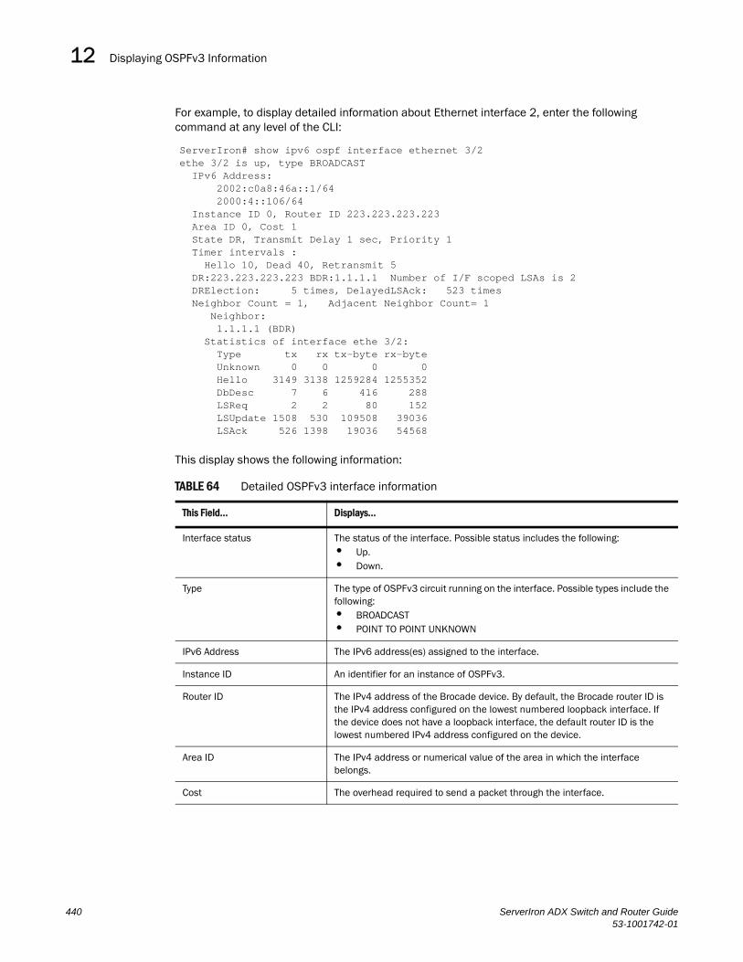
Displaying OSPFv3 Information12DRAFT: BROCADE CONFIDENTIAL
For example, to display detailed information about Ethernet interface 2, enter the following command at any level of the CLI:
This display shows the following information:
TABLE 64 Detailed OSPFv3 interface information
This Field... Displays...
Interface status The status of the interface. Possible status includes the following:• Up.• Down.
Type The type of OSPFv3 circuit running on the interface. Possible types include the following:• BROADCAST• POINT TO POINT UNKNOWN
IPv6 Address The IPv6 address(es) assigned to the interface.
Instance ID An identifier for an instance of OSPFv3.
Router ID The IPv4 address of the Brocade device. By default, the Brocade router ID is the IPv4 address configured on the lowest numbered loopback interface. If the device does not have a loopback interface, the default router ID is the lowest numbered IPv4 address configured on the device.
Area ID The IPv4 address or numerical value of the area in which the interface belongs.
Cost The overhead required to send a packet through the interface.
ServerIron# show ipv6 ospf interface ethernet 3/2ethe 3/2 is up, type BROADCAST IPv6 Address: 2002:c0a8:46a::1/64 2000:4::106/64 Instance ID 0, Router ID 223.223.223.223 Area ID 0, Cost 1 State DR, Transmit Delay 1 sec, Priority 1 Timer intervals : Hello 10, Dead 40, Retransmit 5 DR:223.223.223.223 BDR:1.1.1.1 Number of I/F scoped LSAs is 2 DRElection: 5 times, DelayedLSAck: 523 times Neighbor Count = 1, Adjacent Neighbor Count= 1 Neighbor: 1.1.1.1 (BDR) Statistics of interface ethe 3/2: Type tx rx tx-byte rx-byte Unknown 0 0 0 0 Hello 3149 3138 1259284 1255352 DbDesc 7 6 416 288 LSReq 2 2 80 152 LSUpdate 1508 530 109508 39036 LSAck 526 1398 19036 54568
440 ServerIron ADX Switch and Router Guide53-1001742-01
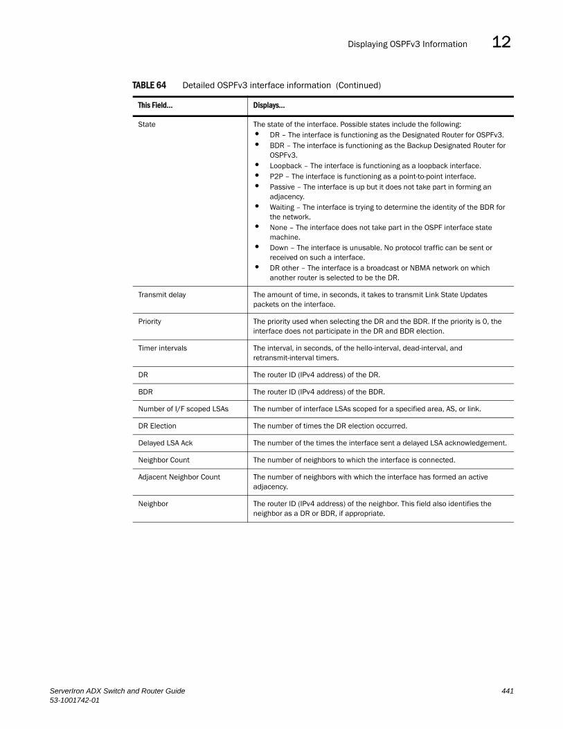
Displaying OSPFv3 Information 12DRAFT: BROCADE CONFIDENTIAL
State The state of the interface. Possible states include the following:• DR – The interface is functioning as the Designated Router for OSPFv3.• BDR – The interface is functioning as the Backup Designated Router for
OSPFv3.• Loopback – The interface is functioning as a loopback interface.• P2P – The interface is functioning as a point-to-point interface.• Passive – The interface is up but it does not take part in forming an
adjacency.• Waiting – The interface is trying to determine the identity of the BDR for
the network. • None – The interface does not take part in the OSPF interface state
machine.• Down – The interface is unusable. No protocol traffic can be sent or
received on such a interface. • DR other – The interface is a broadcast or NBMA network on which
another router is selected to be the DR.
Transmit delay The amount of time, in seconds, it takes to transmit Link State Updates packets on the interface.
Priority The priority used when selecting the DR and the BDR. If the priority is 0, the interface does not participate in the DR and BDR election.
Timer intervals The interval, in seconds, of the hello-interval, dead-interval, and retransmit-interval timers.
DR The router ID (IPv4 address) of the DR.
BDR The router ID (IPv4 address) of the BDR.
Number of I/F scoped LSAs The number of interface LSAs scoped for a specified area, AS, or link.
DR Election The number of times the DR election occurred.
Delayed LSA Ack The number of the times the interface sent a delayed LSA acknowledgement.
Neighbor Count The number of neighbors to which the interface is connected.
Adjacent Neighbor Count The number of neighbors with which the interface has formed an active adjacency.
Neighbor The router ID (IPv4 address) of the neighbor. This field also identifies the neighbor as a DR or BDR, if appropriate.
TABLE 64 Detailed OSPFv3 interface information (Continued)
This Field... Displays...
ServerIron ADX Switch and Router Guide 44153-1001742-01
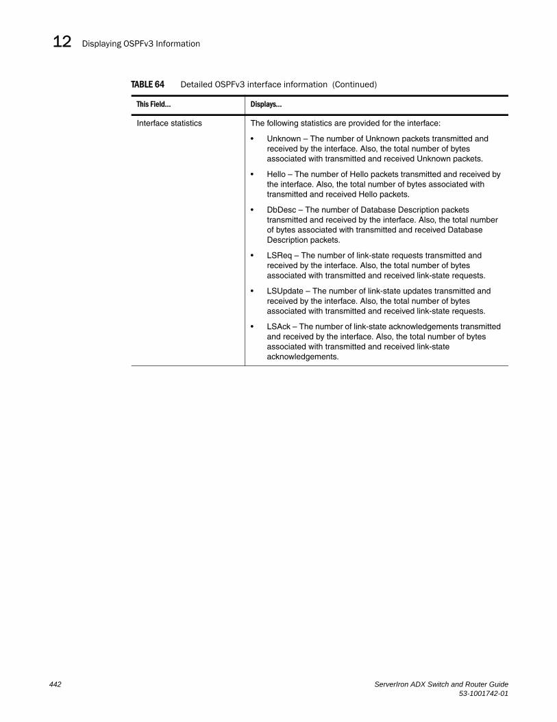
Displaying OSPFv3 Information12DRAFT: BROCADE CONFIDENTIAL
Interface statistics The following statistics are provided for the interface:
• Unknown – The number of Unknown packets transmitted and received by the interface. Also, the total number of bytes associated with transmitted and received Unknown packets.
• Hello – The number of Hello packets transmitted and received by the interface. Also, the total number of bytes associated with transmitted and received Hello packets.
• DbDesc – The number of Database Description packets transmitted and received by the interface. Also, the total number of bytes associated with transmitted and received Database Description packets.
• LSReq – The number of link-state requests transmitted and received by the interface. Also, the total number of bytes associated with transmitted and received link-state requests.
• LSUpdate – The number of link-state updates transmitted and received by the interface. Also, the total number of bytes associated with transmitted and received link-state requests.
• LSAck – The number of link-state acknowledgements transmitted and received by the interface. Also, the total number of bytes associated with transmitted and received link-state acknowledgements.
TABLE 64 Detailed OSPFv3 interface information (Continued)
This Field... Displays...
442 ServerIron ADX Switch and Router Guide53-1001742-01
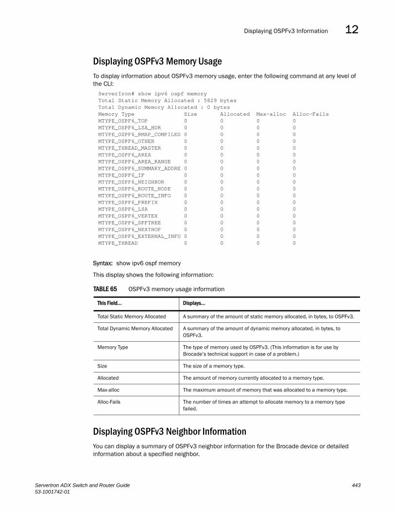
Displaying OSPFv3 Information 12DRAFT: BROCADE CONFIDENTIAL
Displaying OSPFv3 Memory UsageTo display information about OSPFv3 memory usage, enter the following command at any level of the CLI:
Syntax: show ipv6 ospf memory
This display shows the following information:
Displaying OSPFv3 Neighbor InformationYou can display a summary of OSPFv3 neighbor information for the Brocade device or detailed information about a specified neighbor.
TABLE 65 OSPFv3 memory usage information
This Field... Displays...
Total Static Memory Allocated A summary of the amount of static memory allocated, in bytes, to OSPFv3.
Total Dynamic Memory Allocated A summary of the amount of dynamic memory allocated, in bytes, to OSPFv3.
Memory Type The type of memory used by OSPFv3. (This information is for use by Brocade’s technical support in case of a problem.)
Size The size of a memory type.
Allocated The amount of memory currently allocated to a memory type.
Max-alloc The maximum amount of memory that was allocated to a memory type.
Alloc-Fails The number of times an attempt to allocate memory to a memory type failed.
ServerIron# show ipv6 ospf memoryTotal Static Memory Allocated : 5829 bytesTotal Dynamic Memory Allocated : 0 bytesMemory Type Size Allocated Max-alloc Alloc-FailsMTYPE_OSPF6_TOP 0 0 0 0MTYPE_OSPF6_LSA_HDR 0 0 0 0MTYPE_OSPF6_RMAP_COMPILED 0 0 0 0MTYPE_OSPF6_OTHER 0 0 0 0MTYPE_THREAD_MASTER 0 0 0 0MTYPE_OSPF6_AREA 0 0 0 0MTYPE_OSPF6_AREA_RANGE 0 0 0 0MTYPE_OSPF6_SUMMARY_ADDRE 0 0 0 0MTYPE_OSPF6_IF 0 0 0 0MTYPE_OSPF6_NEIGHBOR 0 0 0 0MTYPE_OSPF6_ROUTE_NODE 0 0 0 0MTYPE_OSPF6_ROUTE_INFO 0 0 0 0MTYPE_OSPF6_PREFIX 0 0 0 0MTYPE_OSPF6_LSA 0 0 0 0MTYPE_OSPF6_VERTEX 0 0 0 0MTYPE_OSPF6_SPFTREE 0 0 0 0MTYPE_OSPF6_NEXTHOP 0 0 0 0MTYPE_OSPF6_EXTERNAL_INFO 0 0 0 0MTYPE_THREAD 0 0 0 0
ServerIron ADX Switch and Router Guide 44353-1001742-01

Displaying OSPFv3 Information12DRAFT: BROCADE CONFIDENTIAL
To display a summary of OSPFv3 neighbor information for the device, enter the following command at any CLI level:
Syntax: show ipv6 ospf neighbor [router-id <ipv4-address>]
The router-id <ipv4-address> parameter displays only the neighbor entries for the specified router.
This display shows the following information:
TABLE 66 Summary of OSPFv3 neighbor information
Field Description
Router ID The IPv4 address of the neighbor. By default, the Brocade router ID is the IPv4 address configured on the lowest numbered loopback interface. If the device does not have a loopback interface, the default router ID is the lowest numbered IPv4 address configured on the device.
Pri The OSPFv3 priority of the neighbor. The priority is used during election of the DR and BDR.
State The state between the Brocade device and the neighbor. The state can be one of the following:• Down• Attempt• Init• 2-Way• ExStart• Exchange• Loading • Full
DR The router ID (IPv4 address) of the DR.
BDR The router ID (IPv4 address) of the BDR.
Interface [State] The interface through which the router is connected to the neighbor. The state of the interface can be one of the following:• DR – The interface is functioning as the Designated Router for OSPFv3.• BDR – The interface is functioning as the Backup Designated Router for OSPFv3.• Loopback – The interface is functioning as a loopback interface.• P2P – The interface is functioning as a point-to-point interface.• Passive – The interface is up but it does not take part in forming an adjacency.• Waiting – The interface is trying to determine the identity of the BDR for the network. • None – The interface does not take part in the OSPF interface state machine.• Down – The interface is unusable. No protocol traffic can be sent or received on such a
interface. • DR other – The interface is a broadcast or NBMA network on which another router is
selected to be the DR.
ServerIron# show ipv6 ospf neighborRouterID Pri State DR BDR Interface[State]1.1.1.1 1 Full 223.223.223.223 1.1.1.1 ethe 3/2 [DR]
444 ServerIron ADX Switch and Router Guide53-1001742-01

Displaying OSPFv3 Information 12DRAFT: BROCADE CONFIDENTIAL
For example, to display detailed information about a neighbor with the router ID of 1.1.1.1, enter the following command at any CLI level:
This display shows the following information:
TABLE 67 Detailed OSPFv3 neighbor information
Field Description
Router ID For information about this field, see Table 66 on page 444.
Pri For information about this field, see Table 66 on page 444.
State For information about this field, see Table 66 on page 444.
DR For information about this field, see Table 66 on page 444.
BDR For information about this field, see Table 66 on page 444.
Interface [State] For information about this field, see Table 66 on page 444.
DbDesc bit... The Database Description packet, which includes 3 bits of information:• The first bit can be “i” or “-”. “i” indicates the inet bit is set. “-” indicates the
inet bit is not set.• The second bit can be “m” or “-”. “m” indicates the more bit is set. “-”
indicates the more bit is not set.• The third bit can be “m” or “s”. An “m” indicates the master. An “s” indicates
standby.
Index The ID of the LSA from which the neighbor learned of the router.
DR Decision The router ID (IPv4 address) of the neighbor’s elected DR and BDR.
Last Received Db Desc The content of the last database description received from the specified neighbor.
Number of LSAs in Db Desc retransmitting
The number of LSAs that need to be retransmitted to the specified neighbor.
Number of LSAs in Summary List
The number of LSAs in the neighbor’s summary list.
Number of LSAs in Request List
The number of LSAs in the neighbor’s request list.
ServerIron#show ipv6 ospf neighbor router-id 3.3.3.3RouterID Pri State DR BDR Interface[State]3.3.3.3 1 Full 3.3.3.3 1.1.1.1 ve 10 [BDR]DbDesc bit for this neighbor: --sNbr Ifindex of this router: 1Nbr DRDecision: DR 3.3.3.3, BDR 1.1.1.1Last received DbDesc: opt:xxx ifmtu:0 bit:--s seqnum:0Number of LSAs in DbDesc retransmitting: 0Number of LSAs in SummaryList: 0Number of LSAs in RequestList: 0Number of LSAs in RetransList: 0SeqnumMismatch 0 times, BadLSReq 0 timesOnewayReceived 0 times, InactivityTimer 0 timesDbDescRetrans 0 times, LSReqRetrans 0 timesLSUpdateRetrans 1 timesLSAReceived 12 times, LSUpdateReceived 6 times
ServerIron ADX Switch and Router Guide 44553-1001742-01
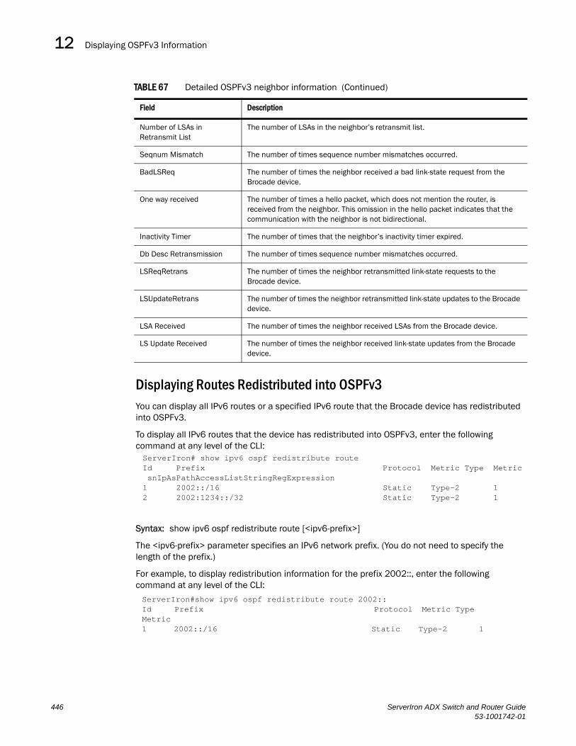
Displaying OSPFv3 Information12DRAFT: BROCADE CONFIDENTIAL
Displaying Routes Redistributed into OSPFv3You can display all IPv6 routes or a specified IPv6 route that the Brocade device has redistributed into OSPFv3.
To display all IPv6 routes that the device has redistributed into OSPFv3, enter the following command at any level of the CLI:
Syntax: show ipv6 ospf redistribute route [<ipv6-prefix>]
The <ipv6-prefix> parameter specifies an IPv6 network prefix. (You do not need to specify the length of the prefix.)
For example, to display redistribution information for the prefix 2002::, enter the following command at any level of the CLI:
Number of LSAs in Retransmit List
The number of LSAs in the neighbor’s retransmit list.
Seqnum Mismatch The number of times sequence number mismatches occurred.
BadLSReq The number of times the neighbor received a bad link-state request from the Brocade device.
One way received The number of times a hello packet, which does not mention the router, is received from the neighbor. This omission in the hello packet indicates that the communication with the neighbor is not bidirectional.
Inactivity Timer The number of times that the neighbor’s inactivity timer expired.
Db Desc Retransmission The number of times sequence number mismatches occurred.
LSReqRetrans The number of times the neighbor retransmitted link-state requests to the Brocade device.
LSUpdateRetrans The number of times the neighbor retransmitted link-state updates to the Brocade device.
LSA Received The number of times the neighbor received LSAs from the Brocade device.
LS Update Received The number of times the neighbor received link-state updates from the Brocade device.
TABLE 67 Detailed OSPFv3 neighbor information (Continued)
Field Description
ServerIron# show ipv6 ospf redistribute routeId Prefix Protocol Metric Type Metric snIpAsPathAccessListStringRegExpression1 2002::/16 Static Type-2 12 2002:1234::/32 Static Type-2 1
ServerIron#show ipv6 ospf redistribute route 2002::Id Prefix Protocol Metric Type Metric1 2002::/16 Static Type-2 1
446 ServerIron ADX Switch and Router Guide53-1001742-01

Displaying OSPFv3 Information 12DRAFT: BROCADE CONFIDENTIAL
These displays show the following information:
Displaying OSPFv3 Route InformationYou can display the entire OSPFv3 route table for the Brocade device or only the route entries for a specified destination.
To display the entire OSPFv3 route table for the device, enter the following command at any level of the CLI:
Syntax: show ipv6 ospf routes [<ipv6-prefix>]
The <ipv6-prefix> parameter specifies a destination IPv6 prefix. (You do not need to specify the length of the prefix.) If you use this parameter, only the route entries for this destination are shown.
For example, to display route information for the destination prefix 2000:4::, enter the following command at any level of the CLI:
TABLE 68 OSPFv3 redistribution information
This Field... Displays...
ID An ID for the redistributed route.
Prefix The IPv6 routes redistributed into OSPFv3.
Protocol The protocol from which the route is redistributed into OSPFv3. Redistributed protocols can be the following:• Static – IPv6 static route table.• Connected – A directly connected network.
Metric Type The metric type used for routes redistributed into OSPFv3. The metric type can be the following:• Type-1 – Specifies a small metric (2 bytes).• Type-2 – Specifies a big metric (3 bytes).
Metric The value of the default redistribution metric, which is the OSPF cost of redistributing the route into OSPFv3.
ServerIron# show ipv6 ospf routesCurrent Route count: 4 Intra: 4 Inter: 0 External: 0 (Type1 0/Type2 0) Equal-cost multi-path: 0 Destination Options Area Cost Type2 C Next Hop Router Outgoing Interface*IA 2000:4::/64 V6E---R-- 0.0.0.0 1 0 :: ethe 3/2*IA 2002:c0a8:46a::/64 V6E---R-- 0.0.0.0 1 0 :: ethe 3/2*IA 2999::1/128 --------- 0.0.0.0 0 0 :: loopback 2*IA 2999::2/128 V6E---R-- 0.0.0.0 1 0 fe80::2e0:52ff:fe91:bb37 ethe 3/2
ServerIron#show ipv6 ospf routes 2000:4:: Destination Options Area Cost Type2 Cost Next Hop Router Outgoing Interface*IA 2000:4::/64 V6E---R-- 0.0.0.0 1 0 :: ethe 3/2
ServerIron ADX Switch and Router Guide 44753-1001742-01
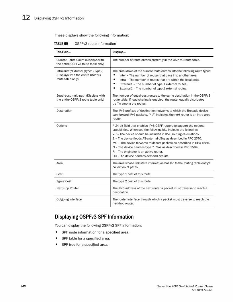
Displaying OSPFv3 Information12DRAFT: BROCADE CONFIDENTIAL
These displays show the following information:
Displaying OSPFv3 SPF InformationYou can display the following OSPFv3 SPF information:
• SPF node information for a specified area.
• SPF table for a specified area.
• SPF tree for a specified area.
TABLE 69 OSPFv3 route information
This Field... Displays...
Current Route Count (Displays with the entire OSPFv3 route table only)
The number of route entries currently in the OSPFv3 route table.
Intra/Inter/External (Type1/Type2) (Displays with the entire OSPFv3 route table only)
The breakdown of the current route entries into the following route types:• Inter – The number of routes that pass into another area.• Intra – The number of routes that are within the local area.• External1 – The number of type 1 external routes.• External2 – The number of type 2 external routes.
Equal-cost multi-path (Displays with the entire OSPFv3 route table only)
The number of equal-cost routes to the same destination in the OSPFv3 route table. If load sharing is enabled, the router equally distributes traffic among the routes.
Destination The IPv6 prefixes of destination networks to which the Brocade device can forward IPv6 packets. “*IA” indicates the next router is an intra-area router.
Options A 24-bit field that enables IPv6 OSPF routers to support the optional capabilities. When set, the following bits indicate the following:V6 – The device should be included in IPv6 routing calculations.E – The device floods AS-external-LSAs as described in RFC 2740.MC – The device forwards multicast packets as described in RFC 1586.N – The device handles type 7 LSAs as described in RFC 1584.R – The originator is an active router.DC –The device handles demand circuits.
Area The area whose link state information has led to the routing table entry's collection of paths.
Cost The type 1 cost of this route.
Type2 Cost The type 2 cost of this route.
Next-Hop Router The IPv6 address of the next router a packet must traverse to reach a destination.
Outgoing Interface The router interface through which a packet must traverse to reach the next-hop router.
448 ServerIron ADX Switch and Router Guide53-1001742-01

Displaying OSPFv3 Information 12DRAFT: BROCADE CONFIDENTIAL
For example, to display information about SPF nodes in area 0, enter the following command at any level of the CLI:
Syntax: show ipv6 ospf spf node area [<area-id>]
The node keyword displays SPF node information.
The area <area-id> parameter specifies a particular area. You can specify the <area-id> in the following formats:
• As an IPv4 address; for example, 192.168.1.1.
• As a numerical value from 0 – 2,147,483,647.
This display shows the following information:
TABLE 70 OSPFv3 SPF node information
This Field... Displays...
SPF node Each SPF node is identified by its router ID (IPv4 address). If the node is a child node, it is additionally identified by an interface on which the node can be reached appended to the router ID in the format <router-id>:<interface-id>.
Cost The cost of traversing the SPF node to reach the destination.
Hops The number of hops needed to reach the parent SPF node.
Next Hops to Node The IPv6 address of the next hop-router and/or the router interface through which to access the next-hop router.
Parent Nodes The SPF node’s parent nodes. A parent node is an SPF node at the highest level of the SPF tree, which is identified by its router ID.
Child Nodes The SPF node’s child nodes. A child node is an SPF node at a lower level of the SPF tree, which is identified by its router ID and interface on which the node can be reached.
ServerIron# show ipv6 ospf spf node area 0SPF node for Area 0SPF node 223.223.223.223, cost: 0, hops: 0 nexthops to node: parent nodes: child nodes: 223.223.223.223:88
SPF node 223.223.223.223:88, cost: 1, hops: 1 nexthops to node: :: ethe 3/2 parent nodes: 223.223.223.223 child nodes: 1.1.1.1:0
SPF node 1.1.1.1:0, cost: 1, hops: 2 nexthops to node: fe80::2e0:52ff:fe91:bb37 ethe 3/2 parent nodes: 223.223.223.223:88 child nodes:
ServerIron ADX Switch and Router Guide 44953-1001742-01

Displaying OSPFv3 Information12DRAFT: BROCADE CONFIDENTIAL
For example, to display the SPF table for area 0, enter the following command at any level of the CLI:
Syntax: show ipv6 ospf spf table area <area-id>
The table parameter displays the SPF table.
The area <area-id> parameter specifies a particular area. You can specify the <area-id> in the following formats:
• As an IPv4 address, for example, 192.168.1.1.
• As a numerical value from 0 – 2,147,483,647.
This display shows the following information:
ServerIron# show ipv6 ospf spf table area 0 SPF table for Area 0 Destination Bits Options Cost Nexthop InterfaceR 1.1.1.1 ---- V6E---R- 1 fe80::2e0:52ff:fe91:bb37 ethe 3/2N 223.223.223.223[88] ---- V6E---R- 1 :: ethe 3/2
TABLE 71 OSPFv3 SPF Table
This Field... Displays...
Destination The destination of a route, which is identified by the following:• “R”, which indicates the destination is a router. “N”, which indicates the
destination is a network.• An SPF node’s router ID (IPv4 address). If the node is a child node, it is
additionally identified by an interface on which the node can be reached appended to the router ID in the format <router-id>:<interface-id>.
Bits A bit that indicates the capability of the Brocade device. The bit can be set to one of the following:• B – The device is an area border router.• E – The device is an AS boundary router.• V – The device is a virtual link endpoint.• W – The device is a wildcard multicast receiver.
Options A 24-bit field that enables IPv6 OSPF routers to support the optional capabilities. When set, the following bits indicate the following:V6 – The router should be included in IPv6 routing calculations.E – The router floods AS-external-LSAs as described in RFC 2740.MC – The router forwards multicast packets as described in RFC 1586.N – The router handles type 7 LSAs as described in RFC 1584.R – The originator is an active router.DC –The router handles demand circuits.
Cost The cost of traversing the SPF node to reach the destination.
Next hop The IPv6 address of the next hop-router.
Interface The router interface through which to access the next-hop router.
450 ServerIron ADX Switch and Router Guide53-1001742-01

Displaying OSPFv3 Information 12DRAFT: BROCADE CONFIDENTIAL
For example, to display the SPF tree for area 0, enter the following command at any level of the CLI:
Syntax: show ipv6 ospf spf tree area <area-id>
The tree keyword displays the SPF table.
The area <area-id> parameter specifies a particular area. You can specify the <area-id> in the following formats:
• As an IPv4 address; for example, 192.168.1.1.
• As a numerical value from 0 – 2,147,483,647.
In this sample output, consider the SPF node with the router ID 223.223.223.223 to be the top (root) of the tree and the local router. Consider all other layers of the tree (223.223.223.223:88 and 1.1.1.1:0) to be destinations in the network. Therefore, traffic destined from router 223.223.223.223 to router 1.1.1.1:0 must first traverse router 223.223.223.223:88.
Displaying IPv6 OSPF Virtual Link InformationTo display OSPFv3 virtual link information for the Brocade device, enter the following command at any level of the CLI:
Syntax: show ipv6 ospf virtual-link
This display shows the following information:
TABLE 72 OSPFv3 virtual link information
This Field... Displays...
Index An index number associated with the virtual link.
Transit Area ID The ID of the shared area of two ABRs that serves as a connection point between the two routers.
Router ID IPv4 address of the router at the other end of the virtual link (virtual neighbor).
Interface Address The local address used to communicate with the virtual neighbor.
State The state of the virtual link. Possible states include the following:• P2P – The link is functioning as a point-to-point interface.• DOWN – The link is down.
ServerIron#s how ipv6 ospf spf tree area 0 SPF tree for Area 0 +- 223.223.223.223 cost 0 +- 223.223.223.223:88 cost 1 +- 1.1.1.1:0 cost 1
ServerIron# show ipv6 ospf virtual-linkIndex Transit Area ID Router ID Interface Address State1 1 1.1.1.1 3003::2
ServerIron ADX Switch and Router Guide 45153-1001742-01

Displaying OSPFv3 Information12DRAFT: BROCADE CONFIDENTIAL
Displaying OSPFv3 Virtual Neighbor InformationTo display OSPFv3 virtual neighbor information for the Brocade device, enter the following command at any level of the CLI:
Syntax: show ipv6 ospf virtual-neighbor
This display shows the following information:
ServerIron#show ipv6 ospf virtual-neighborIndex Router ID Address State Interface1 1.1.1.1 3002::1 Full ethe 2/3
TABLE 73 OSPFv3 virtual neighbor information
This Field... Displays...
Index An index number associated with the virtual neighbor.
Router ID IPv4 address of the virtual neighbor.
Address The IPv6 address to be used for communication with the virtual neighbor.
State The state between the Brocade device and the virtual neighbor. The state can be one of the following:• Down• Attempt• Init• 2-Way• ExStart• Exchange• Loading• Full
Interface The IPv6 address of the virtual neighbor.
452 ServerIron ADX Switch and Router Guide53-1001742-01

ServerIron ADX Switch and Router Guide53-1001742-01
DRAFT: BROCADE CONFIDENTIAL
Chapter
13
sFlowIn this Chapter•In this Chapter . . . . . . . . . . . . . . . . . . . . . . . . . . . . . . . . . . . . . . . . . . . . . . . . 453
•Overview. . . . . . . . . . . . . . . . . . . . . . . . . . . . . . . . . . . . . . . . . . . . . . . . . . . . . 453
•Configuration considerations . . . . . . . . . . . . . . . . . . . . . . . . . . . . . . . . . . . . 453
•Configuring and enabling sFlow . . . . . . . . . . . . . . . . . . . . . . . . . . . . . . . . . . 454
OverviewsFlow is a system for observing traffic flow patterns and quantities within and among a set of ServerIron ADX devices. Participating devices also relay byte and packet counter data (counter samples) for ports to the collector.
sFlow is described in RFC 3176, “InMon Corporation's sFlow, A Method for Monitoring Traffic in Switched and Routed Networks”. Refer to this RFC to determine the contents of the sampled packet.
Configuration considerationsConsider the following when you configure sFlow:
• Sample data is collected from inbound traffic on ports enabled for sFlow. However, both traffic directions are counted for byte and packet counter statistics sent to the collector.
Source addressThe sampled sFlow data sent to the collectors includes an agent_address field. This field identifies the IP address of the device that sent the data.
sFlow looks for an IP address in following order, and uses the first address found:
• The router ID configured by the ip router-id command
• The first IP address on the lowest-numbered loopback interface
• The first IP address on the lowest-numbered virtual interface
• The first IP address on any interface
NOTEThe device uses the router ID only if the device also has an IP interface with the same address.
453

Configuring and enabling sFlow13DRAFT: BROCADE CONFIDENTIAL
NOTEIf an IP address in not already configured when you enable sFlow, the feature uses the source address 0.0.0.0. To display the agent_address, enable sFlow, then enter the show sflow command. Refer to “Enabling sFlow forwarding” on page 457 and “Clearing sFlow statistics” on page 459.
NOTEIf you change the address sFlow will use for the agent_address, you must disable and re-enable sFlow to enable the feature to use the changed address.
Sampling rateThe sampling rate is the ratio of the number of packets incoming on an sflow enabled port, to the number of flow samples taken from those packets. ServerIron ADX ports send only the sampled traffic to the CPU. sFlow sampling requires high management CPU usage, which can affect performance in some configurations especially if a high sampling rate is configured.
Extended router information
Extended router information contains information for the next hop router. This information includes the next hop router’s IP address and the outgoing VLAN ID.
Configuring and enabling sFlowTo configure sFlow:
• Specify collector information. The collector is the external device to which you are exporting the sFlow data. You can specify up to four collectors.
• Optional – Change the polling interval.
• Optional – Change the sampling rate.
• Enable sFlow globally.
• Enable sFlow forwarding on individual interfaces.
NOTEIf you change the router ID or other IP address value that sFlow uses for its agent_address, you need to disable and then re-enable sFlow to cause the feature to use the new source address.
Specifying the collectorsFlow exports traffic statistics to an external collector. You can specify up to four collectors. You can specify more than one collector with the same IP address if the UDP port numbers are unique. You can have up to four unique combinations of IP address and UDP port number.
To specify sFlow collectors, enter a command such as the following.
ServerIron ADX(config)# sflow destination 10.10.10.1
This command specifies a collector with IP address 10.10.10.1, listening for sFlow data on UDP port 6343.
454 ServerIron ADX Switch and Router Guide53-1001742-01

Configuring and enabling sFlow 13DRAFT: BROCADE CONFIDENTIAL
Syntax: [no] sflow destination <ip-addr> [<dest-udp-port>]
The <ip-addr> parameter specifies the collector’s IP address.
The <dest-udp-port> parameter specifies the UDP port on which the sFlow collector will be listening for exported sFlow data. The default port number is 6343.
The sampled sFlow data sent to the collectors includes an agent_address field. This field identifies the device that sent the data. Refer to “Source address” on page 453.
Changing the polling intervalThe polling interval defines how often sFlow byte and packet counter data for a port are sent to the sFlow collectors. If multiple ports are enabled for sFlow, the ServerIron ADX staggers transmission of the counter data to smooth performance. For example, if sFlow is enabled on two ports and the polling interval is 20 seconds, the ServerIron ADX sends counter data every ten seconds. The counter data for one of the ports are sent after ten seconds, and counter data for the other port are sent after an additional ten seconds. Ten seconds later, new counter data for the first port are sent. Similarly, if sFlow is enabled on five ports and the polling interval is 20 seconds, the ServerIron ADX sends counter data every four seconds.
The default polling interval is 20 seconds. You can change the interval to a value from 1 to any higher value. The interval value applies to all interfaces on which sFlow is enabled. If you set the polling interval to 0, counter data sampling is disabled.
To change the polling interval, enter a command such as the following at the global CONFIG level of the CLI.
ServerIron ADX(config)# sflow polling-interval 30
Syntax: [no] sflow polling-interval <secs>
The <secs> parameter specifies the interval and can be from 1 to any higher value. The default is 20 seconds. If you specify 0, counter data sampling is disabled.
Changing the sampling rateThe sampling rate is the ratio of the number of packets incoming on an sFlow-enabled port, to the number of flow samples taken from those packets. By default, all sFlow-enabled ports use the default sampling rate, which is 2048. With a sampling rate of 2048, on average, one in every 2048 packets forwarded on an interface is sampled.
You can change the default (global) sampling rate. You also can change the rate on an individual port, overriding the default sampling rate.
NOTEsFlow uses CPU resources to send sFlow samples to the collector. If you set a low sampling rate, CPU utilization can become high.
ServerIron ADX Switch and Router Guide 45553-1001742-01
Configuring and enabling sFlow13DRAFT: BROCADE CONFIDENTIAL
Configuration considerations
The sampling rate is a fraction in the form 1/N, meaning that, on average, one out of every N packets will be sampled. The sflow sample command at the global level or port level specifies N, the denominator of the fraction. Thus a higher number for the denominator means a lower sampling rate since fewer packets are sampled. Likewise, a lower number for the denominator means a higher sampling rate because more packets are sampled. For example, if you change the denominator from 2,000 to 512, the sampling rate increases because four times as many packets will be sampled.
On ServerIron ADX devices, the sampling rate can be configured between 1 and 16777215. The sampling rate programmed in the hardware may be slightly different than the configured sampling rate. This happens due to a rounding off process in the hardware registers. For example, a sampling rate of 100000 will be programmed in hardware as 1000462. The show sflow command displays the configured and the actual sampling rates.
NOTEBrocade recommends that you do not change the denominator to a value lower than the default. Sampling requires CPU resources. Using a low denominator for the sampling rate can cause high CPU utilization.
Change to global rateIf you change the global sampling rate, the change is applied to all sFlow-enabled ports except those ports on which you have already explicitly set the sampling rate. For example, suppose that sFlow is enabled on ports 1/1, 1/2, and 5/1. If you configure the sampling rate on port 1/1 but leave the other two ports using the default rate, then a change to the global sampling rate applies to ports 1/2 and 5/1 but not port 1/1. sFlow assumes that you want to continue using the sampling rate you explicitly configured on an individual port even if you globally change the sampling rate for the other ports.
Sampling rate for new portsWhen you enable sFlow on a port, the port's sampling rate is set to the global default sampling rate. This also applies to ports on which you disable and then re-enable sFlow. The port does not retain the sampling rate it had when you disabled sFlow on the port, even if you had explicitly set the sampling rate on the port.
Changing the default sampling rate
To change the default (global) sampling rate, enter a command such as the following at the global CONFIG level of the CLI.
ServerIron ADX(config)# sflow sample 4096
Syntax: [no] sflow sample <num>
The <num> parameter specifies the average number of packets from which each sample will be taken.
456 ServerIron ADX Switch and Router Guide53-1001742-01

Configuring and enabling sFlow 13DRAFT: BROCADE CONFIDENTIAL
Changing the sampling rate on a port
You can configure an individual port to use a different sampling rate than the global default sampling rate. This is useful in cases where ports have different bandwidths. For example, if you are using sFlow on 10/100 ports and Gigabit Ethernet ports, you might want to configure the Gigabit ports to use a higher sampling rate (and thus gather fewer samples per number of packets) than the 10/100 ports.
To change the sampling rate on an individual port, enter a command such as the following at the configuration level for the port.
ServerIron ADX(config-if-e10000-1/1)# sflow sample 8192
Syntax: [no] sflow sample <num>
The <num> parameter specifies the average number of packets from which each sample will be taken.
Enabling sFlow forwardingsFlow exports data only for the interfaces on which you enable sFlow forwarding. You can enable sFlow forwarding on the Ethernet interfaces
To enable sFlow forwarding:
• Globally enable the sFlow feature.
• Enable sFlow forwarding on individual interfaces.
NOTEBefore you enable sFlow, make sure the device has an IP address that sFlow can use as its source address. Refer to “Source address” on page 453 for the source address requirements.
To enable sFlow forwarding, enter commands such as the following.
ServerIron ADX(config)# sflow enableServerIron ADX(config)# interface ethernet 1/1 to 1/8ServerIron ADX(config-mif-1/1-1/8)# sflow forwarding
These commands globally enable sFlow, then enable sFlow forwarding on Ethernet ports 1/1 – 1/8. You must use both the sflow enable and sflow forwarding commands to enable the feature.
Syntax: [no] sflow enable
Syntax: [no] sflow forwarding
Configuring sFlow on trunk portssflow for trunk ports can be configured under the trunk configuration mode. If the trunk is not in "config-trunk-ind" mode then only the primary port of the trunk can be configured for sFlow. The secondary trunk ports use the primary port's configuration. If the trunk is configured in "config-trunk-ind" then all trunk ports can be individually configured for sFlow. In this case, each trunk port can be configured with a different sampling rate.
Example
ServerIron ADX(config)# trunk e 1/3 to 1/4ServerIron ADX(config-trunk-1/3-1/4)# config-trunk-indServerIron ADX(config-trunk-1/3-1/4)# sflow forwarding e 1/4
ServerIron ADX Switch and Router Guide 45753-1001742-01

Configuring and enabling sFlow13DRAFT: BROCADE CONFIDENTIAL
ServerIron ADX(config-trunk-1/3-1/4)# sflow sample e 1/4 4096
The above example shows how to enter into trunk configuration mode. The command "config-trunk-ind" allows the trunk ports to be configured independently for certain features. The sflow forwarding and sampling rate is configured on 1/4 but not on 1/3.
It is also possible to configure sFlow by directly going into the trunk's primary interface configuration mode. Depending on the "config-trunk-ind" mode of the trunk, the sFlow configuration may or may not apply to the secondary trunk ports. Brocade recommends using the trunk configuration mode to configure sFlow on trunk ports.
For dynamio trunk ports (LACP trunks), sFlow cannot be applied on individual trunk ports. For such ports, apply sFlow on the primary port of the trunk. A primary port’s sFlow configuration applies to all of the other ports on the trunk. Any sFlow configuration on the non-primary ports of the trunk that existed before the trunk was formed will be ignored and overwritten by the primary port’s sFlow configuration.
Displaying sFlow informationTo display sFlow configuration information and statistics, enter the following command at any level of the CLI.
Syntax: show sflow
This command shows the following information.
TABLE 74 sFlow information
This field... Displays...
sFlow services The feature state, which can be one of the following:• disabled• enabled
sFlow agent IP address The IP address that sFlow is using in the agent_address field of packets sent to the collectors. Refer to “Source address” on page 453.
Collector The collector information. The following information is displayed for each collector:• IP address• UDP portIf more than one collector is configured, the line above the collectors indicates how many have been configured.
ServerIron ADX(config)#show sflowsFlow services are enabled.sFlow agent IP address: 10.10.10.3Collector IP 10.45.24.32, UDP 6343Polling interval is 0 seconds.Configured default sampling rate: 1 per 2048 packets.20 UDP packets exported85 sFlow samples collected.sFlow ports: ethe 1/2 to 1/3 ethe 2/1 Port Sampling Rates-------------------Port=1/2, configured rate=4096, actual rate=4096Port=1/3, configured rate=4096, actual rate=4096Port=2/1, configured rate=2048, actual rate=2048
458 ServerIron ADX Switch and Router Guide53-1001742-01

Configuring and enabling sFlow 13DRAFT: BROCADE CONFIDENTIAL
Clearing sFlow statisticsTo clear the UDP packet and sFlow sample counters in the show sflow display, enter the following command.
ServerIron ADX(config)# clear statistics.
Syntax: clear statistics
This command clears the values in the following fields of the show sflow display:
• UDP packets exported
• sFlow samples collected
NOTEThis command also clears the statistics counters used by other features.
Polling interval The port counter polling interval.
Configured default sampling rate The configured global sampling rate. If you changed the global sampling rate, the value you entered is shown here. The actual rate calculated by the software based on the value you entered is listed on the next line, ”Actual default sampling rate”.
UDP packets exported The number of sFlow export packets the ServerIron ADX has sent.
NOTE: Each UDP packet can contain multiple samples.
sFlow samples collected The number of sampled packets that have been sent to the collectors.
sFlow ports The ports on which you enabled sFlow.
Port Sampling Rates The sampling rates of a port on which sFlow is enabled (configured and actual).
TABLE 74 sFlow information (Continued)
This field... Displays...
ServerIron ADX Switch and Router Guide 45953-1001742-01

Configuring and enabling sFlow13DRAFT: BROCADE CONFIDENTIAL
460 ServerIron ADX Switch and Router Guide53-1001742-01