Christie’s Exceptional Sale 2013 Realises £15 Million/$22.9 Million/€17.6 Million

Heavy Vehicle Products
Series KV2 Fittings and TIV TubingFMVSS (DOT) & SAE Compliant
• One-touch connection reduces installation time and cost.
• Rugged ultraviolet and vibration resistant composite body.
• Various shapes and configurations to meet vehicleapplications and make installation easier.
NC127-B
1
2
3
4
5
6 7
8
9
10
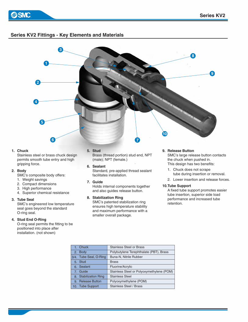
Series KV2 Fittings - Key Elements and Materials
Series KV2
1. ChuckStainless steel or brass chuck designpermits smooth tube entry and highgripping force.
2. BodySMC’s composite body offers:1. Weight savings2. Compact dimensions3. High performance4. Superior chemical resistance
3. Tube SealSMC’s engineered low temperatureseal goes beyond the standardO-ring seal.
4. Stud End O-RingO-ring seal permits the fitting to bepositioned into place afterinstallation. (not shown)
9. Release ButtonSMC’s large release button contactsthe chuck when pushed in.This design has two benefits:
1. Chuck does not scrapetube during insertion or removal.
2. Lower insertion and release forces.
10.Tube SupportA fixed tube support promotes easiertube insertion, superior side loadperformance and increased tuberetention.
5. StudBrass (thread portion) stud end, NPT(male); NPT (female.)
6. SealantStandard, pre-applied thread sealantfacilitates installation.
7. GuideHolds internal components togetherand also guides release button.
8. Stabilization RingSMC’s patented stabilization ringensures high temperature stabilityand maximum performance with asmaller overall package.
Stainless Steel or Brass
Polybutylene Terephthalate (PBT), Brass
Buna-N, Nitrile Rubber
Brass
Fluorine/Acrylic
Stainless Steel or Polyoxymethylene (POM)
Stainless Steel
Polyoxymethylene (POM)
Stainless Steel / Brass
1.
2.
3/4.
5.
6.
7.
8.
9.
10.
Chuck
Body
Tube Seal, O-Ring
Stud
Sealant
Guide
Stabilization Ring
Release Button
Tube Support

Series KV2
SpecificationsHow to OrderMale ConnectorStraight SAE FlareFemale ConnectorStraight UnionPlug-in ReducerPlug-in 90° ElbowPlug-In “Y”90° Male Elbow90° Female ElbowUnion 90° Elbow45° Male Elbow45° Female ElbowMale Run TeeMale Branch TeeFemale Branch TeeUnion TeeMale Branch “Y”Union “Y”Male Double “Y”Union Double “Y”Universal Female 90° ElbowMale Double Universal 90° ElbowMale Branch Universal 90° ElbowBulkhead UnionFemale Bulkhead ConnectorPlugsColor CapsFitting BootsAccessories (Cutters)SMC CartridgesStraight Cartridge45° Elbow Cartridge90° Elbow CartridgeTIV Nylon TubingInstructionsImportant DOs and DON’TsSpecific Precautions for Fittings on VehiclesChemical Resistance ChartTerms of SaleReturn Policy
123344555677889
1010111112121313141415151616161718191920212223
24-25262728
KV2H _ _-_ _SKV2H _ _-S_ _KV2F _ _-_ _KV2H _ _-_ _KV2R _ _-_ _KV2L _ _-99KV2U _ _-99KV2L _ _-_ _SKV2LF _ _-_ _KV2L _ _-00KV2K _ _-_ _SKV2KF _ _-_ _KV2Y _ _-_ _SKV2T _ _-_ _SKV2TF _ _-_ _KV2T _ _-_ _KV2U _ _-_ _SKV2U _ _-_ _KV2UD _ _-_ _SKV2UD _ _-_ _KV2VF _ _-_ _SKV2VD _ _-_ _SKV2Z _ _-_ _SKV2E _ _-_ _KV2E _ _-_ _KV2P-_ _KQ2C _ _ [ _ _ ]KR-_ _C
KV2H_ _-Q_ _KV2K_ _-Q_ _KV2L_ _-Q_ _
KV2 One-TouchBody Page #
Table of Contents
1
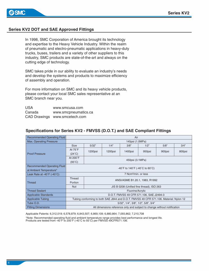
Series KV2 DOT and SAE Approved Fittings
Series KV2
In 1998, SMC Corporation of America brought its technologyand expertise to the Heavy Vehicle Industry. Within the realmof pneumatic and electro-pneumatic applications in heavy-dutytrucks, buses, trailers and a variety of other suppliers to thisindustry, SMC products are state-of-the-art and always on thecutting edge of technology.
SMC takes pride in our ability to evaluate an industry’s needsand develop the systems and products to maximize efficiencyof assembly and operation.
For more information on SMC and its heavy vehicle products,please contact your local SMC sales representative at anSMC branch near you.
USACanadaCAD Drawings
www.smcusa.comwww.smcpneumatics.cawww.smcetech.com
Recommended Operating Fluid
Max. Operating Pressure
Proof Pressure
Recommended Operating Fluid
at Ambient Temperature*
Leak Rate at -40˚F (-40˚C)
Thread
Thread Sealant
Applicable Standards
Applicable Tubing
Tube O.D.
Fitting Dimensions
Air
145psi (1.0MPa)
450psi (3.1MPa)
-40˚F to 140˚F (-40˚C to 60˚C)
Size
At 75˚F
(24˚C)
At 200˚F
(93˚C)
Thread
Portion
Nut
3/8”1/4” 1/2”5/32” 5/8” 3/4”
7 Ncm³/min. or less
ANSI/ASME B1.20.1, 1983, R1992
JIS B 0208 (Unified fine thread), ISO 263
Fluorine/Acrylic
D.O.T. FMVSS 49 CFR 571.106, SAE J2494-3
Tubing conforming to both SAE J844 and D.O.T. FMVSS 49 CFR 571.106. Material: Nylon 12
5/32”, 1/4”, 3/8”, 1/2”, 5/8”, 3/4”
All dimensions reference only and subject to change without notification
Specifications for Series KV2 - FMVSS (D.O.T.) and SAE Compliant Fittings
Applicable Patents: 6,312,019; 6,578,879; 6,843,507; 6,869,109; 6,880,864; 7,093,862; 7,210,708
*Note: Recommended operating fluid and ambient temperature range provides best performance and longest life.Products are tested from -40˚F to 200˚F (-40˚C to 93˚C) per FMVSS 49CFR571.106.
1400psi1200psi 950psi1200psi 900psi 800psi
2
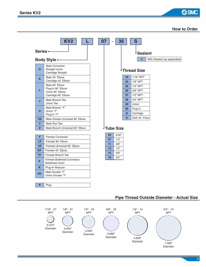
Series KV2
How to Order
Male ConnectorStraight UnionCartridge Straight
Male 45˚ ElbowCartridge 45˚ Elbow
Male 90˚ ElbowPlug-In 90˚ ElbowUnion 90˚ ElbowCartridge 90˚ Elbow
Male Branch TeeUnion Tee
Male Branch “Y”Union “Y”Plug-In “Y”
Male Double Universal 90˚ Elbow
Male Run Tee
Male Branch Universal 90˚ Elbow
VD
Y
Z
T
U
H
L
K
Female Bulkhead ConnectorBulkhead Union
E
Plug-In ReducerR
Male Double “Y”Union Double “Y”
UD
Female Branch TeeTF
Female 45˚ ElbowKF
Female Universal 90˚ ElbowVF
Female 90˚ ElbowLF
Female ConnectorF
PlugP
KV2 L 07 35 S
Series
Body Style
Tube Size
3/4”19
5/8”15
1/2”13
3/8”11
1/4”07
5/32”03
Thread Size
3/4” NPT38
1/2” NPT37
3/8” NPT36
1/4” NPT35
1/8” NPT34
1/16” NPT33
CartridgeQ
SAE 45˚ FlareS
Plug-In99
Union00
SealantWith Sealant (as applicable)S
-
Pipe Thread Outside Diameter - Actual Size
1/16” - 27NPT
0.313”Diameter
1/8” - 27NPT
0.453”Diameter
1/4” - 18NPT
0.540”Diameter
3/8” - 18NPT
0.666”Diameter
1/2” - 14NPT
0.840”Diameter
3/4” - 14NPT
1.050”Diameter
3
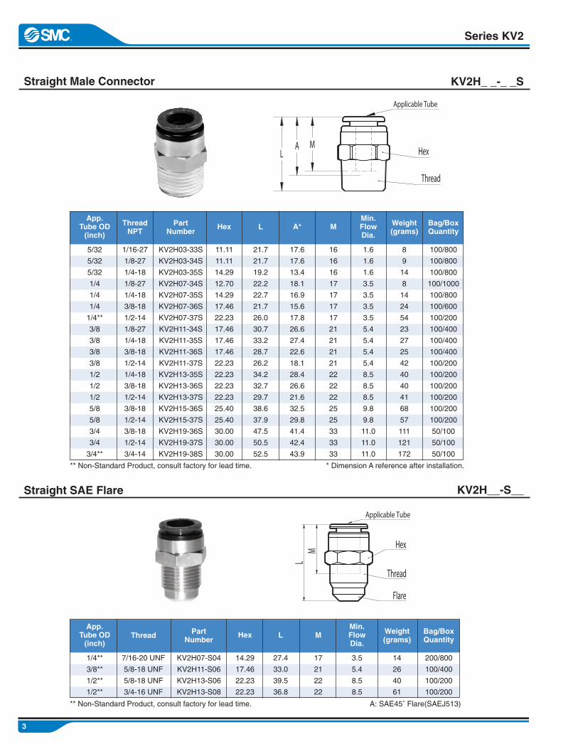
Straight Male Connector KV2H_ _-_ _S
Series KV2
Straight SAE Flare KV2H__-S__
5/32
5/32
5/32
1/4
1/4
1/4
1/4**
3/8
3/8
3/8
3/8
1/2
1/2
1/2
5/8
5/8
3/4
3/4
3/4**
1/16-27
1/8-27
1/4-18
1/8-27
1/4-18
3/8-18
1/2-14
1/8-27
1/4-18
3/8-18
1/2-14
1/4-18
3/8-18
1/2-14
3/8-18
1/2-14
3/8-18
1/2-14
3/4-14
11.11
11.11
14.29
12.70
14.29
17.46
22.23
17.46
17.46
17.46
22.23
22.23
22.23
22.23
25.40
25.40
30.00
30.00
30.00
KV2H03-33S
KV2H03-34S
KV2H03-35S
KV2H07-34S
KV2H07-35S
KV2H07-36S
KV2H07-37S
KV2H11-34S
KV2H11-35S
KV2H11-36S
KV2H11-37S
KV2H13-35S
KV2H13-36S
KV2H13-37S
KV2H15-36S
KV2H15-37S
KV2H19-36S
KV2H19-37S
KV2H19-38S
21.7
21.7
19.2
22.2
22.7
21.7
26.0
30.7
33.2
28.7
26.2
34.2
32.7
29.7
38.6
37.9
47.5
50.5
52.5
17.6
17.6
13.4
18.1
16.9
15.6
17.8
26.6
27.4
22.6
18.1
28.4
26.6
21.6
32.5
29.8
41.4
42.4
43.9
16
16
16
17
17
17
17
21
21
21
21
22
22
22
25
25
33
33
33
1.6
1.6
1.6
3.5
3.5
3.5
3.5
5.4
5.4
5.4
5.4
8.5
8.5
8.5
9.8
9.8
11.0
11.0
11.0
8
9
14
8
14
24
54
23
27
25
42
40
40
41
68
57
111
121
172
100/800
100/800
100/800
100/1000
100/800
100/600
100/200
100/400
100/400
100/400
100/200
100/200
100/200
100/200
100/200
100/200
50/100
50/100
50/100
App.Tube OD(inch)
ThreadNPT
HexPartNumber
L A* MMin.FlowDia.
Weight(grams)
Bag/BoxQuantity
1/4**
3/8**
1/2**
1/2**
7/16-20 UNF
5/8-18 UNF
5/8-18 UNF
3/4-16 UNF
14.29
17.46
22.23
22.23
KV2H07-S04
KV2H11-S06
KV2H13-S06
KV2H13-S08
27.4
33.0
39.5
36.8
17
21
22
22
3.5
5.4
8.5
8.5
14
26
40
61
200/800
100/400
100/200
100/200
App.Tube OD(inch)
Thread HexPartNumber
L MMin.FlowDia.
Weight(grams)
Bag/BoxQuantity
** Non-Standard Product, consult factory for lead time. * Dimension A reference after installation.
** Non-Standard Product, consult factory for lead time. A: SAE45˚ Flare(SAEJ513)
LA M
Applicable Tube
Hex
Thread
Applicable Tube
LM Hex
Thread
Flare
4
Series KV2
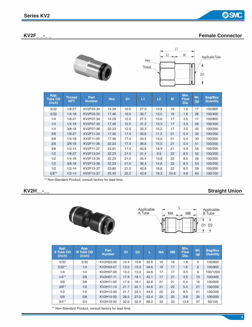
Female ConnectorKV2F_ _-_ _
5/32
5/32
1/4
1/4
1/4
3/8
3/8
3/8
3/8
1/2
1/2
1/2
1/2
5/8**
1/8-27
1/4-18
1/8-27
1/4-18
3/8-18
1/8-27
1/4-18
3/8-18
1/2-14
1/8-27
1/4-18
3/8-18
1/2-14
1/2-14
14.29
17.46
14.29
17.46
22.23
17.46
17.46
22.23
23.81
22.23
22.23
22.23
23.80
25.40
KV2F03-34
KV2F03-35
KV2F07-34
KV2F07-35
KV2F07-36
KV2F11-34
KV2F11-35
KV2F11-36
KV2F11-37
KV2F13-34
KV2F13-35
KV2F13-36
KV2F13-37
KV2F15-37
10.0
10.0
12.5
12.5
12.5
17.4
17.4
17.4
17.4
21.0
21.0
21.0
21.0
25.2
27.0
30.7
27.5
31.2
33.3
30.8
34.5
36.6
40.6
31.4
35.4
36.4
40.8
42.9
10.8
13.5
10.6
13.3
15.2
11.3
15.0
15.5
18.9
9.9
13.8
14.8
18.8
18.3
1.6
1.6
3.5
3.5
3.5
5.4
5.4
5.4
5.4
8.5
8.5
8.5
8.5
9.8
17
26
17
26
45
32
33
51
55
52
59
53
59
84
100/800
100/400
100/800
100/400
100/200
100/200
100/200
100/200
100/200
100/200
100/200
100/200
100/200
100/100
App.Tube OD(inch)
ThreadNPT
HexPartNumber
D1 L1 L2Min.FlowDia.
Wt.(g)
Bag/BoxQuantity
5/32
5/32**
1/4
1/4**
3/8
3/8**
1/2
5/8
3/4**
KV2H03-00
KV2H03-07
KV2H07-00
KV2H07-11
KV2H11-00
KV2H11-13
KV2H13-00
KV2H15-00
KV2H19-00
10.4
13.2
13.2
17.9
17.9
21.7
21.7
26.5
32.6
1.6
1.6
3.5
3.5
5.4
5.4
8.5
9.8
13.6
5
6
6
15
15
21
21
35
57
100/800
100/800
100/1200
100/400
100/600
100/200
100/200
100/200
50/100
App.A Tube OD(inch)
PartNumber
D1Min.FlowDia.
Wt.(g)
Bag/BoxQuantity
** Non-Standard Product, consult factory for lead time.
** Non-Standard Product, consult factory for lead time.
Straight UnionKV2H__-__
16
16
17
17
17
21
21
21
21
22
22
22
22
24.6
M
5/32
1/4
1/4
3/8
3/8
1/2
1/2
5/8
3/4
App.B Tube OD(inch)
10.6
13.3
13.3
18.1
18.1
22.1
22.1
27.0
32.9
D2
32.6
34.6
34.6
42.1
42.6
44.6
44.6
53.4
68.2
L
16
16
17
17
21
21
22
25
33
MA
16
17
17
21
21
22
22
25
33
MB
L1
L2 M
D1
Hex
Thread
Applicable Tube
L
MA MB
D1 D2
ApplicableA Tube
ApplicableB Tube
L
D1 D2
L1
D3
L2
A
M Applicable Tube
Applicable Fitting
5
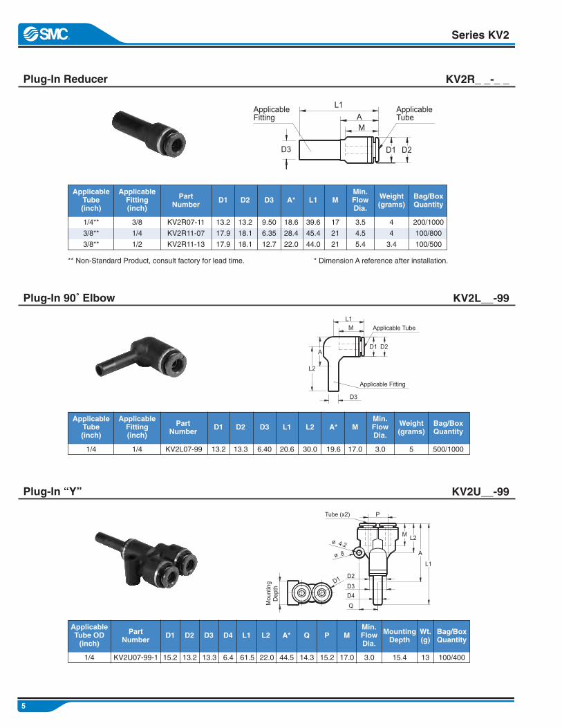
Plug-In Reducer KV2R_ _-_ _
Series KV2
1/4**
3/8**
3/8**
KV2R07-11
KV2R11-07
KV2R11-13
13.2
17.9
17.9
3.5
4.5
5.4
4
4
3.4
200/1000
100/800
100/500
ApplicableTube(inch)
PartNumber
D1Min.FlowDia.
Weight(grams)
Bag/BoxQuantity
** Non-Standard Product, consult factory for lead time. * Dimension A reference after installation.
Plug-In 90˚ Elbow KV2L__-99
Plug-In “Y” KV2U__-99
3/8
1/4
1/2
ApplicableFitting(inch)
13.2
18.1
18.1
D2
9.50
6.35
12.7
D3
18.6
28.4
22.0
A*
39.6
45.4
44.0
L1
17
21
21
M
1/4 KV2L07-99 13.2 3.0 5 500/1000
ApplicableTube(inch)
PartNumber
D1Min.FlowDia.
Weight(grams)
Bag/BoxQuantity
1/4
ApplicableFitting(inch)
13.3
D2
6.40
D3
19.6
A*
20.6
L1
17.0
M
30.0
L2
1/4 KV2U07-99-1 15.2 3.0 13 100/400
ApplicableTube OD(inch)
PartNumber
D1Min.FlowDia.
Wt.(g)
Bag/BoxQuantity
13.2
D2
13.3
D3
44.5
A*
61.5
L1
17.0
M
22.0
L2
6.4
D4
14.3
Q
15.2
P
15.4
MountingDepth
L1
MA
D1 D2D3
ApplicableFitting
ApplicableTube
L1
L2
P
D2
D3
D4
Q
ø 4.2
ø 8 A
M
Tube (x2)
Dep
thM
ount
ing D1

6
Series KV2
90˚ Male ElbowKV2L_ _-_ _S
5/32
5/32**
1/4
1/4
1/4
1/4**
3/8
3/8
3/8
3/8
1/2
1/2
1/2
1/2**
5/8
5/8
5/8**
3/4
3/4**
1/8-27
1/4-27
1/8-27
1/4-18
3/8-18
1/2-14
1/8-27
1/4-18
3/8-18
1/2-14
1/4-18
3/8-18
1/2-14
3/4-14
3/8-18
1/2-14
3/4-14
1/2-14
3/4-14
14.29
14.29
14.29
14.29
17.46
22.23
19.00
19.00
19.00
22.23
19.00
19.00
22.23
28.57
23.80
23.80
28.57
28.57
28.57
KV2L03-34S
KV2L03-35S
KV2L07-34S
KV2L07-35S
KV2L07-36S
KV2L07-37S
KV2L11-34S
KV2L11-35S
KV2L11-36S
KV2L11-37S
KV2L13-35S
KV2L13-36S
KV2L13-37S
KV2L13-38S
KV2L15-36S
KV2L15-37S
KV2L15-38S
KV2L19-37S
KV2L19-38S
13.2
13.2
13.2
13.2
13.2
13.2
17.9
17.9
17.9
17.9
21.7
21.7
21.7
21.7
26.5
26.5
26.5
32.6
32.6
25.9
28.2
25.9
28.2
29.9
31.9
31.5
32.8
34.5
36.5
36.6
38.3
40.3
42.9
45.0
46.0
48.8
53.7
56.3
16
16
17
17
17
17
21
21
21
21
22
22
22
22
25
25
25
33
33
1.6
1.6
3.5
3.5
3.5
3.5
5.4
5.4
5.4
5.4
8.5
8.5
8.5
8.5
9.8
9.8
9.8
12.8
12.8
13
20
13
20
34
65
30
28
37
63
32
41
65
70
64
80
132
116
150
100/800
100/600
100/800
100/600
100/400
100/200
100/400
100/400
100/200
100/200
100/200
100/200
100/200
50/100
100/200
100/100
50/50
50/100
50/100
App.Tube OD(inch)
ThreadNPT
HexPartNumber
D1
13.2
13.2
13.3
13.3
13.3
13.3
18.1
18.1
18.1
18.1
22.1
22.1
22.1
22.1
27.0
27.0
27.0
32.9
32.9
D2
13.2
13.2
13.2
13.2
13.2
13.2
17.0
17.0
17.0
17.0
17.0
17.0
17.0
17.0
20.9
20.9
20.9
26.2
26.2
D3
13.2
13.2
13.2
13.2
13.2
13.2
17.9
17.9
17.9
17.9
17.9
17.9
17.9
17.9
21.9
21.9
21.9
27.0
27.0
D4
20.6
20.6
20.6
20.6
20.6
20.6
26.2
26.2
26.2
26.2
28.8
28.8
28.8
29.0
33.4
33.4
33.4
44.1
44.1
L1
23.4
27.4
23.4
27.4
29.4
33.4
26.6
29.6
31.6
35.6
31.5
33.5
37.5
40.7
37.8
40.8
44.1
45.5
48.7
L2 A* MMin.FlowDia.
Weight(grams)
Bag/BoxQuantity
** Non-Standard Product, consult factory for lead time. * Dimension A reference after installation.
ML1
D1 D2
A
L2
D3D4
Hex
Thread
ApplicableTube

7
90˚ Female Elbow KV2LF_ _-_ _
Series KV2
5/32
5/32
1/4
1/4
1/4
3/8
3/8
3/8
3/8
1/2
1/2
1/2
5/8**
1/8-27
1/4-18
1/8-27
1/4-18
3/8-18
1/8-27
1/4-18
3/8-18
1/2-14
1/4-18
3/8-18
1/2-14
1/2-14
14.29
17.46
14.29
17.46
22.23
17.46
17.46
22.23
23.80
17.46
22.23
23.80
23.80
KV2LF03-34
KV2LF03-35
KV2LF07-34
KV2LF07-35
KV2LF07-36
KV2LF11-34
KV2LF11-35
KV2LF11-36
KV2LF11-37
KV2LF13-35
KV2LF13-36
KV2LF13-37
KV2LF15-37
13.2
13.2
13.2
13.2
13.2
17.9
17.9
17.9
17.9
21.7
21.7
21.7
26.5
16
16
17
17
17
21
21
21
21
22
22
22
25
1.6
1.6
3.5
3.5
3.5
5.4
5.4
5.4
5.4
8.5
8.5
8.5
9.8
15
23
14
23
35
22
31
43
47
35
47
52
60
100/400
100/400
100/800
100/400
100/200
100/200
100/200
100/200
100/200
100/200
100/200
100/200
50/100
App.Tube OD(inch)
ThreadNPT
HexPartNumber
D1
13.2
13.2
13.3
13.3
13.3
18.1
18.1
18.1
18.1
22.1
22.1
22.1
27.0
D2
13.2
13.2
13.2
13.2
13.2
17.0
17.0
17.0
17.0
17.0
17.0
17.0
20.9
D3
13.2
13.2
13.2
13.2
13.2
17.9
17.9
17.9
17.9
17.9
17.9
17.9
21.9
D4
20.6
20.6
20.6
20.6
20.6
26.2
26.2
26.2
26.2
28.8
28.8
28.8
33.5
L1
22.0
25.5
22.0
25.5
26.0
18.8
27.7
28.2
32.2
29.6
30.1
34.1
37.5
L2 MMin.FlowDia.
Weight(grams)
Bag/BoxQuantity
** Non-Standard Product, consult factory for lead time.
5/32
1/4
3/8
1/2
KV2L03-00
KV2L07-00
KV2L11-00
KV2L13-00
10.4
13.2
17.9
21.7
16
17
21
22
1.6
3.5
5.4
8.5
5
7
16
23
100/800
100/1000
100/400
100/200
App.Tube OD(inch)
PartNumber
D1
10.6
13.3
18.1
22.1
D2
18.3
20.6
26.1
28.9
L
4.5
5.3
6.6
7.8
Q MMin.FlowDia.
Weight(grams)
Bag/BoxQuantity
Union 90˚ Elbow KV2L_ _-00
L1M
D1 D2
L2
D3D4
Applicable Tube
Hex
Thread
D1
D2
D1 D2
L
M
M
L
Q
ApplicableTube
8
Series KV2
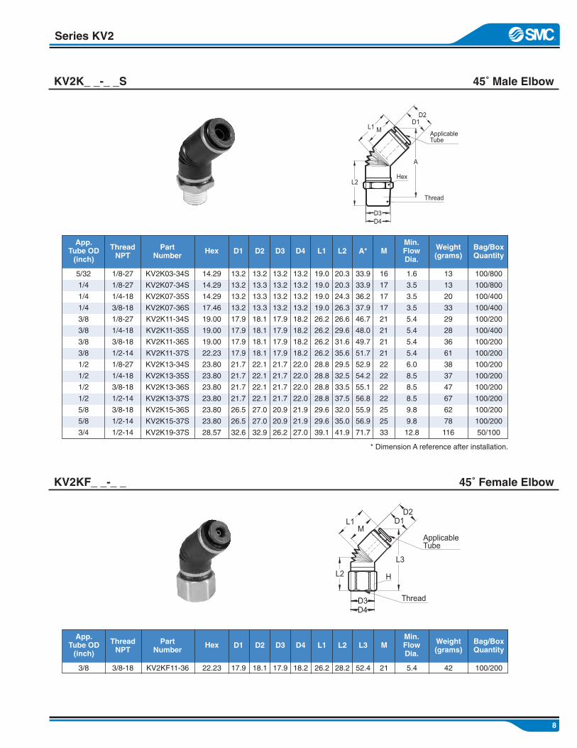
45˚ Male ElbowKV2K_ _-_ _S
5/32
1/4
1/4
1/4
3/8
3/8
3/8
3/8
1/2
1/2
1/2
1/2
5/8
5/8
3/4
1/8-27
1/8-27
1/4-18
3/8-18
1/8-27
1/4-18
3/8-18
1/2-14
1/8-27
1/4-18
3/8-18
1/2-14
3/8-18
1/2-14
1/2-14
14.29
14.29
14.29
17.46
19.00
19.00
19.00
22.23
23.80
23.80
23.80
23.80
23.80
23.80
28.57
KV2K03-34S
KV2K07-34S
KV2K07-35S
KV2K07-36S
KV2K11-34S
KV2K11-35S
KV2K11-36S
KV2K11-37S
KV2K13-34S
KV2K13-35S
KV2K13-36S
KV2K13-37S
KV2K15-36S
KV2K15-37S
KV2K19-37S
13.2
13.2
13.2
13.2
17.9
17.9
17.9
17.9
21.7
21.7
21.7
21.7
26.5
26.5
32.6
16
17
17
17
21
21
21
21
22
22
22
22
25
25
33
1.6
3.5
3.5
3.5
5.4
5.4
5.4
5.4
6.0
8.5
8.5
8.5
9.8
9.8
12.8
13
13
20
33
29
28
36
61
38
37
47
67
62
78
116
100/800
100/800
100/400
100/400
100/200
100/400
100/200
100/200
100/200
100/200
100/200
100/200
100/200
100/200
50/100
App.Tube OD(inch)
ThreadNPT
HexPartNumber
13.2
13.3
13.3
13.3
18.1
18.1
18.1
18.1
22.1
22.1
22.1
22.1
27.0
27.0
32.9
D2
13.2
13.2
13.2
13.2
17.9
17.9
17.9
17.9
21.7
21.7
21.7
21.7
20.9
20.9
26.2
D3
13.2
13.2
13.2
13.2
18.2
18.2
18.2
18.2
22.0
22.0
22.0
22.0
21.9
21.9
27.0
D4
19.0
19.0
19.0
19.0
26.2
26.2
26.2
26.2
28.8
28.8
28.8
28.8
29.6
29.6
39.1
L1
20.3
20.3
24.3
26.3
26.6
29.6
31.6
35.6
29.5
32.5
33.5
37.5
32.0
35.0
41.9
L2 MMin.FlowDia.
Weight(grams)
Bag/BoxQuantity
D1
45˚ Female ElbowKV2KF_ _-_ _
33.9
33.9
36.2
37.9
46.7
48.0
49.7
51.7
52.9
54.2
55.1
56.8
55.9
56.9
71.7
A*
3/8 3/8-18 22.23KV2KF11-36 17.9 21 5.4 42 100/200
App.Tube OD(inch)
ThreadNPT
HexPartNumber
18.1
D2
17.9
D3
18.2
D4
26.2
L1
28.2
L2 MMin.FlowDia.
Weight(grams)
Bag/BoxQuantity
D1
52.4
L3
* Dimension A reference after installation.
ML1D1D2
A
D3D4
L2Hex
Thread
ApplicableTube
ML1
L2
L3
D4D3
D1D2
ApplicableTube
H
Thread

9
Male Run Tee KV2Y_ _-_ _S
Series KV2
5/32**
5/32
5/32
5/32
1/4**
1/4
1/4
1/4
3/8**
3/8**
3/8
3/8
3/8
1/2**
1/2**
1/2**
1/2
1/2
1/2
5/8**
1/4-18
1/16-18
1/8-27
1/4-18
1/4-18
1/8-27
1/4-18
3/8-18
1/4-18
3/8-18
1/4-18
3/8-18
1/2-14
1/2-14
3/8-18
1/2-14
1/4-18
3/8-18
1/2-14
1/2-14
14.29
14.29
14.29
14.29
19.00
14.29
14.29
17.46
19.00
19.00
19.00
19.00
22.23
23.80
23.80
22.23
19.00
19.00
22.23
23.80
KV2Y03-07-35S
KV2Y03-33S
KV2Y03-34S
KV2Y03-35S
KV2Y07-11-35S
KV2Y07-34S
KV2Y07-35S
KV2Y07-36S
KV2Y11-07-35S
KV2Y11-07-36S
KV2Y11-35S
KV2Y11-36S
KV2Y11-37S
KV2Y13-07-37S
KV2Y13-11-36S
KV2Y13-11-37S
KV2Y13-35S
KV2Y13-36S
KV2Y13-37S
KV2Y15-37S
13.2
13.2
13.2
13.2
17.9
13.2
13.2
13.2
17.9
17.9
17.9
17.9
17.9
21.7
21.7
21.7
21.7
21.7
21.7
26.5
16
16
16
16
17
17
17
17
21
21
21
21
21
21.8
21.8
21.8
22
22
22
25
1.6
1.6
1.6
1.6
3.5
3.5
3.5
3.5
3.5
3.5
5.4
5.4
5.4
4.6
7.0
7.0
8.5
8.5
8.5
9.8
23
15
16
23
40
16
23
37
40
53
36
44
68
76
64
76
43
51
76
126
100/400
100/400
100/400
100/400
100/200
100/600
100/400
100/400
100/200
100/200
100/200
100/200
100/200
100/100
100/100
100/100
100/200
100/100
100/100
50/100
App. ATube OD(inch)
ThreadNPT
HexPartNumber
D1
13.2
13.2
13.2
13.2
18.1
13.3
13.3
13.3
18.1
18.1
18.1
18.1
18.1
22.1
22.1
22.1
22.1
22.1
22.1
27.0
D2
13.2
13.2
13.2
13.2
17.0
13.2
13.2
13.2
17.0
17.0
17.0
17.0
17.0
17.0
17.0
17.0
17.0
17.0
17.0
20.9
D3
13.2
13.2
13.2
13.2
17.9
13.2
13.2
13.2
17.9
17.9
17.9
17.9
17.9
17.9
17.9
17.9
17.9
17.9
17.9
21.9
D4
20.6
20.6
20.6
20.6
26.2
20.6
20.6
20.6
25.7
25.7
26.2
26.2
26.2
26.6
27.1
27.1
28.8
28.8
28.8
33.5
L1
27.4
23.4
23.4
27.4
29.6
23.4
27.4
29.4
29.6
32.0
29.6
31.6
35.6
35.6
31.6
21.3
31.5
33.5
37.5
41.0
L2
20.6
20.6
20.6
20.6
26.2
20.6
20.6
20.6
25.7
25.7
26.2
26.2
26.2
27.8
27.8
27.8
28.8
28.8
28.8
33.5
L3
46.0
39.9
39.9
42.2
49.6
39.9
42.2
43.9
50.0
51.5
50.0
51.7
53.7
51.8
61.9
63.9
54.5
56.2
58.2
66.0
A* MAMin.FlowDia.
Wt.(g)
Bag/BoxQuantity
** Non-Standard Product, consult factory for lead time. * Dimension A reference after installation.
1/4
5/32
5/32
5/32
3/8
1/4
1/4
1/4
1/4
1/4
3/8
3/8
3/8
1/4
3/8
3/8
1/2
1/2
1/2
5/8
App. BTube OD(inch)
17
16
16
16
21
17
17
17
17
17
21
21
21
16.8
20.4
20.4
2
22
22
25
MB
D1
D2
D4
D3
D5 D6
L1
MA MB
A
L3
L2Hex
Thread
ApplicableTube A
ApplicableTube B
13.2
13.2
13.2
13.2
17.9
13.2
13.2
13.2
17.9
17.9
17.9
17.9
17.9
17.9
17.9
17.9
21.7
21.7
21.7
26.5
D5
13.3
13.2
13.2
13.2
18.1
13.3
13.3
13.3
18.1
18.1
18.1
18.1
18.1
18.1
18.1
18.1
22.1
22.1
22.1
27.0
D6

10
Series KV2
Male Branch TeeKV2T_ _-_ _S
5/32
5/32
5/32
1/4**
1/4**
1/4
1/4
1/4
3/8**
3/8**
3/8
3/8
3/8
3/8
1/2
1/2
1/2
5/8
5/8
1/16-27
1/8-27
1/4-18
1/4-18
3/8-18
1/8-27
1/4-18
3/8-18
3/8-14
1/2-14
1/8-27
1/4-18
3/8-18
1/2-14
1/4-18
3/8-18
1/2-14
3/8-18
1/2-14
14.29
14.29
14.29
19.00
19.00
14.29
14.29
17.46
19.00
22.23
19.00
19.00
19.00
22.23
19.00
19.00
22.23
23.80
23.80
KV2T03-33S
KV2T03-34S
KV2T03-35S
KV2T07-11-35S
KV2T07-11-36S
KV2T07-34S
KV2T07-35S
KV2T07-36S
KV2T11-13-36S
KV2T11-13-37S
KV2T11-34S
KV2T11-35S
KV2T11-36S
KV2T11-37S
KV2T13-35S
KV2T13-36S
KV2T13-37S
KV2T15-36S
KV2T15-37S
13.2
13.2
13.2
17.9
17.9
13.2
13.2
13.2
21.7
21.7
17.9
17.9
17.9
17.9
21.7
21.7
21.7
26.5
26.5
16
16
16
17
17
17
17
17
21
21
21
21
21
21
22
22
22
25
25
1.6
1.6
1.6
3.5
3.5
3.5
3.5
3.5
5.4
5.4
5.4
5.4
5.4
5.4
8.5
8.5
8.5
9.8
9.8
15
15
23
40
42
16
23
36
40
75
37
35
44
68
43
51
75
81
97
100/400
100/400
100/400
100/300
100/200
100/400
100/400
100/400
100/200
100/100
100/200
100/200
100/200
100/200
100/200
100/200
100/100
100/100
100/100
App. ATube OD(inch)
ThreadNPT
HexPartNumber
D1
13.2
13.2
13.2
18.1
18.1
13.3
13.3
13.3
22.1
22.1
18.1
18.1
18.1
18.1
22.1
22.1
22.1
27.0
27.0
D2
13.2
13.2
13.2
17.0
17.0
13.2
13.2
13.2
17.0
17.0
17.0
17.0
17.0
17.0
17.0
17.0
17.0
20.9
20.9
D3
13.2
13.2
13.2
17.9
17.9
13.2
13.2
13.2
17.9
17.9
17.9
17.9
17.9
17.9
17.9
17.9
17.9
21.9
21.9
D4
20.6
20.6
20.6
25.7
25.7
20.6
20.6
20.6
28.8
28.8
26.2
26.2
26.2
26.2
28.8
28.8
28.8
33.4
33.4
L1
23.4
23.4
27.4
29.5
32.1
23.4
27.4
29.4
33.5
37.7
26.6
29.6
31.6
35.6
31.5
33.5
37.5
37.8
40.8
L2
25.9
25.9
28.2
32.7
26.0
25.9
28.2
29.9
38.3
40.4
31.5
32.8
34.5
36.5
36.6
38.3
40.3
45.3
46.0
A* MAMin.FlowDia.
Wt.(g)
Bag/BoxQuantity
** Non-Standard Product, consult factory for lead time. * Dimension A reference after installation.
16
16
16
21
21
17
17
17
22
22
21
21
21
21
22
22
22
25
25
MB
5/32
5/32
5/32
3/8
3/8
1/4
1/4
1/4
1/2
1/2
3/8
3/8
3/8
3/8
1/2
1/2
1/2
5/8
5/8
App. BTube OD(inch)
1/4
1/4
3/8**
3/8
1/2
5/8
1/8-27
1/4-18
1/8-27
1/4-18
3/8-18
1/4-18
14.29
17.46
17.46
17.46
22.23
23.80
KV2TF07-34
KV2TF07-35
KV2TF11-34
KV2TF11-35
KV2TF13-36
KV2TF15-35
13.2
13.2
17.9
17.9
21.7
26.5
17
17
21
21
22
25
3.5
3.5
5.4
5.9
8.5
9.8
28
36
18
38
57
69
100/400
100/400
100/200
100/200
100/200
100/100
App. ATube OD(inch)
ThreadNPT
HexPartNumber
D1
13.3
13.3
18.1
18.1
22.1
27.0
D2
13.2
13.2
17.0
17.0
17.0
20.0
D3
13.2
13.2
17.9
17.9
17.9
21.9
D4
20.6
20.6
26.0
26.2
28.8
33.4
L1
22.0
25.5
19.0
27.7
30.1
25.8
L2 MMin.FlowDia.
Wt.(g)
Bag/BoxQuantity
Female Branch TeeKV2TF_ _-_ _-_
** Non-Standard Product, consult factory for lead time.
L1 L3
MA MB
D1 D2
D4
L2
A
D3
Hex
Thread
ApplicableTube A
ApplicableTube B
M ML1 L1
L2
D1 D2
D3D4
Applicable Tube ( X2 )
Hex
Thread
D4D3
20.6
20.6
20.6
26.2
26.2
20.6
20.6
20.6
28.8
28.8
26.2
26.2
26.2
26.2
28.8
28.8
28.8
33.4
33.4
L3
11
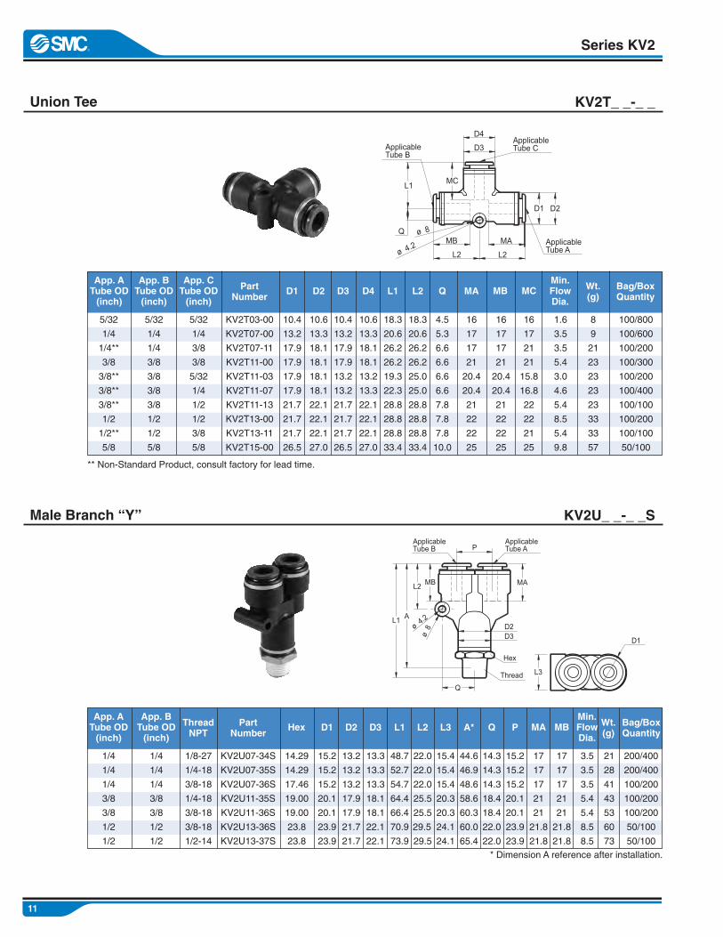
Union Tee KV2T_ _-_ _
Series KV2
5/32
1/4
1/4**
3/8
3/8**
3/8**
3/8**
1/2
1/2**
5/8
KV2T03-00
KV2T07-00
KV2T07-11
KV2T11-00
KV2T11-03
KV2T11-07
KV2T11-13
KV2T13-00
KV2T13-11
KV2T15-00
10.4
13.2
17.9
17.9
17.9
17.9
21.7
21.7
21.7
26.5
16
17
17
21
20.4
20.4
21
22
22
25
1.6
3.5
3.5
5.4
3.0
4.6
5.4
8.5
5.4
9.8
8
9
21
23
23
23
23
33
33
57
100/800
100/600
100/200
100/300
100/200
100/400
100/100
100/200
100/100
50/100
App. ATube OD(inch)
PartNumber
D1
10.6
13.3
18.1
18.1
18.1
18.1
22.1
22.1
22.1
27.0
D2
18.3
20.6
26.2
26.2
19.3
22.3
28.8
28.8
28.8
33.4
L1
4.5
5.3
6.6
6.6
6.6
6.6
7.8
7.8
7.8
10.0
Q
16
17
17
21
20.4
20.4
21
22
22
25
MA MBMin.FlowDia.
Wt.(g)
Bag/BoxQuantity
** Non-Standard Product, consult factory for lead time.
16
17
21
21
15.8
16.8
22
22
21
25
MC
5/32
1/4
1/4
3/8
3/8
3/8
3/8
1/2
1/2
5/8
App. BTube OD(inch)
1/4
1/4
1/4
3/8
3/8
1/2
1/2
1/8-27
1/4-18
3/8-18
1/4-18
3/8-18
3/8-18
1/2-14
14.29
14.29
17.46
19.00
19.00
23.8
23.8
KV2U07-34S
KV2U07-35S
KV2U07-36S
KV2U11-35S
KV2U11-36S
KV2U13-36S
KV2U13-37S
15.2
15.2
15.2
20.1
20.1
23.9
23.9
17
17
17
21
21
21.8
21.8
3.5
3.5
3.5
5.4
5.4
8.5
8.5
21
28
41
43
53
60
73
200/400
200/400
100/200
100/200
100/200
50/100
50/100
App. ATube OD(inch)
ThreadNPT
HexPartNumber
D1
13.2
13.2
13.2
17.9
17.9
21.7
21.7
D2
13.3
13.3
13.3
18.1
18.1
22.1
22.1
D3
48.7
52.7
54.7
64.4
66.4
70.9
73.9
L1
22.0
22.0
22.0
25.5
25.5
29.5
29.5
L2
15.4
15.4
15.4
20.3
20.3
24.1
24.1
L3
44.6
46.9
48.6
58.6
60.3
60.0
65.4
A* MAMin.FlowDia.
Wt.(g)
Bag/BoxQuantity
* Dimension A reference after installation.
17
17
17
21
21
21.8
21.8
MB
1/4
1/4
1/4
3/8
3/8
1/2
1/2
App. BTube OD(inch)
5/32
1/4
3/8
3/8
5/32
1/4
1/2
1/2
3/8
5/8
App. CTube OD(inch)
Male Branch “Y” KV2U_ _-_ _S
14.3
14.3
14.3
18.4
18.4
22.0
22.0
Q
15.2
15.2
15.2
20.1
20.1
23.9
23.9
P
D1 D2
MAQ
L2 L2
MCL1
D4
D3
MB ApplicableTube A
ApplicableTube B
ApplicableTube C
MAMBL2
AL1
Q
P
D3D2ø
4.2
ø8
Thread
Hex
ApplicableTube A
ApplicableTube B
L3
D1
18.3
20.6
26.2
26.2
25.0
25.0
28.8
28.8
28.8
33.4
L2
10.4
13.2
17.9
17.9
13.2
13.2
21.7
21.7
21.7
26.5
D3
10.6
13.3
18.1
18.1
13.2
13.3
22.1
22.1
22.1
27.0
D4
12
Series KV2
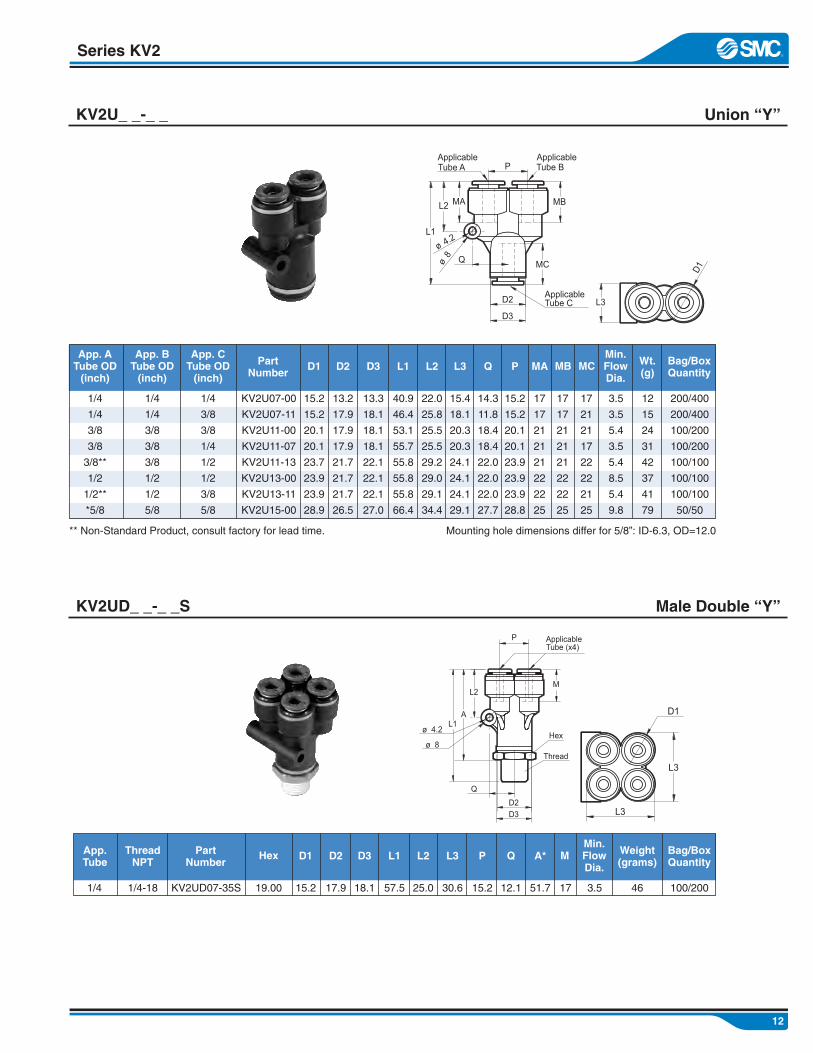
Union “Y”KV2U_ _-_ _
1/4
1/4
3/8
3/8
3/8**
1/2
1/2**
*5/8
KV2U07-00
KV2U07-11
KV2U11-00
KV2U11-07
KV2U11-13
KV2U13-00
KV2U13-11
KV2U15-00
15.2
15.2
20.1
20.1
23.7
23.9
23.9
28.9
17
17
21
21
21
22
22
25
3.5
3.5
5.4
3.5
5.4
8.5
5.4
9.8
12
15
24
31
42
37
41
79
200/400
200/400
100/200
100/200
100/100
100/100
100/100
50/50
App. ATube OD(inch)
PartNumber
D1
13.2
17.9
17.9
17.9
21.7
21.7
21.7
26.5
D2
13.3
18.1
18.1
18.1
22.1
22.1
22.1
27.0
D3
14.3
11.8
18.4
18.4
22.0
22.0
22.0
27.7
Q
17
17
21
21
21
22
22
25
MA MBMin.FlowDia.
Wt.(g)
Bag/BoxQuantity
** Non-Standard Product, consult factory for lead time.
17
21
21
17
22
22
21
25
MC
1/4
1/4
3/8
3/8
3/8
1/2
1/2
5/8
App. BTube OD(inch)
1/4
3/8
3/8
1/4
1/2
1/2
3/8
5/8
App. CTube OD(inch)
Mounting hole dimensions differ for 5/8”: ID-6.3, OD=12.0
1/4 1/4-18 19.00KV2UD07-35S 15.2 17 3.5 46 100/200
ThreadNPT
HexPartNumber
17.9
D2
18.1
D3
57.5
L1
25.0
L2 MMin.FlowDia.
Weight(grams)
Bag/BoxQuantity
D1
30.6
L3
15.2
15.2
20.1
20.1
23.9
23.9
23.9
28.8
P
40.9
46.4
53.1
55.7
55.8
55.8
55.8
66.4
L1
22.0
25.8
25.5
25.5
29.2
29.0
29.1
34.4
L2
15.4
18.1
20.3
20.3
24.1
24.1
24.1
29.1
L3
15.2
P
12.1
Q
51.7
A*App.Tube
Male Double “Y”KV2UD_ _-_ _S
L2
L1
P
D2
D3
Q
ø 4.2
ø8
MBMA
MC
ApplicableTube C
ApplicableTube A
ApplicableTube B
L3
D1
L1A
L2
Q
D2
D3
M
P ApplicableTube (x4)
Hex
Thread
L3
L3
D1
ø 8
ø 4.2
13
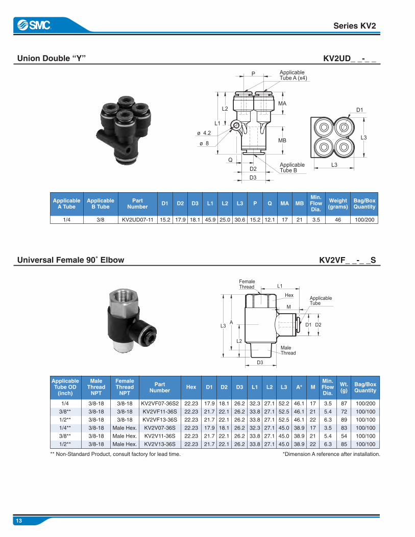
Union Double “Y” KV2UD_ _-_ _
Series KV2
1/4
3/8**
1/2**
1/4**
3/8**
1/2**
KV2VF07-36S2
KV2VF11-36S
KV2VF13-36S
KV2V07-36S
KV2V11-36S
KV2V13-36S
17.9
21.7
21.7
17.9
21.7
21.7
3.5
5.4
6.3
3.5
5.4
6.3
87
72
89
83
54
85
100/200
100/100
100/100
100/100
100/100
100/100
ApplicableTube OD(inch)
PartNumber
D1
18.1
22.1
22.1
18.1
22.1
22.1
D2
26.2
26.2
26.2
26.2
26.2
26.2
D3Min.FlowDia.
Wt.(g)
Bag/BoxQuantity
** Non-Standard Product, consult factory for lead time.
17
21
22
17
21
22
M
3/8-18
3/8-18
3/8-18
3/8-18
3/8-18
3/8-18
MaleThreadNPT
3/8-18
3/8-18
3/8-18
Male Hex.
Male Hex.
Male Hex.
FemaleThreadNPT
*Dimension A reference after installation.
3/8 KV2UD07-11 15.2 3.5 46 100/200
ApplicableB Tube
PartNumber
17.9
D2
18.1
D3
45.9
L1
25.0
L2Min.FlowDia.
Weight(grams)
Bag/BoxQuantity
D1
30.6
L3
32.3
33.8
33.8
32.3
33.8
33.8
L1
27.1
27.1
27.1
27.1
27.1
27.1
L2
52.2
52.5
52.5
45.0
45.0
45.0
L3
15.2
P
12.1
Q
17
MA
Universal Female 90˚ Elbow KV2VF_ _-_ _S
21
MB
1/4
ApplicableA Tube
46.1
46.1
46.1
38.9
38.9
38.9
A*
22.23
22.23
22.23
22.23
22.23
22.23
Hex
L1
L2
D2
D3
Q
ø 8
ø 4.2MB
MA
P ApplicableTube A (x4)
ApplicableTube B
L3
D1
L3
D1 D2
D3
L3
L2
A
L1
M
ThreadMale
Hex
ThreadFemale
ApplicableTube

14
Series KV2
Male Double Universal 90˚ ElbowKV2VD_ _-_ _S
KV2Z07-15-37S
KV2Z11-13-35S
KV2Z11-13-36S1
KV2Z11-13-37S1
KV2Z11-15-37S
KV2Z13-15-37S
28.9
23.9
23.9
23.9
28.9
28.9
3.5
5.4
5.4
5.4
5.4
8.5
159
115
120
133
156
145
30/60
100/100
100/100
100/100
30/60
30/60
PartNumber
D1
29.8
29.8
29.8
29.8
29.8
29.8
D2Min.FlowDia.
Wt.(g)
Bag/BoxQuantity
** Non-Standard Product, consult factory for lead time.
17
21
21
21
21
22
MA
1/2-14
1/4-18
3/8-18
1/2-14
1/2-14
1/2-14
ThreadNPT
*Dimension A reference after installation.
KV2VD11-07-36S3 17.9 3.5 138 50/100
PartNumber
18.1
D2
13.2
D3
33.5
L1
29.8
L2Min.FlowDia.
Wt.(g)
Bag/BoxQty.
D1
24.0
L3
37.9
34.5
34.5
34.5
37.3
36.4
L1
33.7
27.2
28.2
31.2
33.7
33.7
L2
55.0
46.0
47.0
50.0
55.0
55.0
L3
70.0
L4
63.9
A*
21
MA
17
MB
3/8
App. ATube OD(inch)
28.9
23.9
23.9
23.9
28.9
28.9
P
25.40
25.40
25.40
25.40
25.40
25.40
Male Branch Universal 90˚ ElbowKV2Z_ _-_ _S
3/8-18
ThreadNPT
23.8
Hex
26.2
D5
13.3
D4
1/4
App. BTube OD(inch)
1/4
3/8
3/8
3/8
3/8
1/2
App. ATube OD(inch)
5/8
1/2
1/2
1/2
5/8
5/8
App. BTube OD(inch)
Hex
46.9
40.2
40.9
41.9
46.9
46.9
A*
25
22
22
22
25
25
MB
L3
L2
D3 D4
D1 D2
MA
MB
L4A
L1
D5
ApplicableTube A
ApplicableTube B
Hex
Thread
D1
D2
AL3
L2Thread
Hex
P
L1
MB
MA
ApplicableTube B
ApplicableTube A

15
Bulkhead Union KV2E_ _-_ _
Series KV2
KV2E03-00
KV2E07-00
KV2E11-00
KV2E13-00
KV2E15-00
1/2-20
9/16-18
7/8-14
1-12
1 1/8-12
16
17
21
22
25
1.6
3.5
5.4
8.5
9.8
32
30
87
117
191
100/400
100/400
100/100
100/100
50/50
PartNumber
32.1
34.1
42.1
44.1
50.0
L
16
17
21
22
25
MA MBMin.FlowDia.
Wt.(g)
Bag/BoxQuantity
13.5
15.0
23.0
26.0
29.0
5/32
1/4
3/8
1/2
5/8
ApplicableB Tube OD(inch)
5/32
1/4
1/4
3/8
3/8
1/2
1/2
KV2E03-35
KV2E07-34
KV2E07-35
KV2E11-35
KV2E11-36
KV2E13-36
KV2E13-37
1/2-20
9/16-18
9/16-18
7/8-14
7/8-14
1-12
1-12
16
17
17
21
21
22
22
1.6
3.5
3.5
5.4
5.4
8.5
8.5
36
32
36
90
91
120
124
100/400
100/400
100/400
100/100
100/100
100/100
100/100
ApplicableTube OD(inch)
PartNumber
T(UNF)
17.46
17.46
17.46
25.40
25.40
28.57
28.57
H1(Hex)
17.46
17.46
17.46
25.40
25.40
28.57
28.57
H2(Hex)
31.0
27.5
32.4
34.5
36.9
37.1
41.2
L1
14.7
9.8
14.7
12.1
14.5
13.7
17.8
L2 MMin.FlowDia.
Wt.(g)
Bag/BoxQuantity
13.5
15.0
15.0
23.0
23.0
26.0
26.0
D1
Thread(UNF)
17.46
17.46
25.40
28.57
33.33
Hex Mtg.Hole
5/32
1/4
3/8
1/2
5/8
ApplicableA Tube OD(inch)
Female Bulkhead Connector KV2E_ _-_ _
1/4-18
1/8-27
1/4-18
1/4-18
3/8-18
3/8-18
1/2-14
ThreadNPT
L
MA MB
Mounting Plate Max. Thickness : 11mmThreadHex
ApplicableTube B
ApplicableTube A
L1L2
D1
M
Thickness: 7mm max.Mounting Plate
Thread
H1
H2
ApplicableTubeT

16
Series KV2
PlugsKV2P-_ _
All accessories not required to pass FMVSS 106
KV2P-03
KV2P-07
KV2P-11
KV2P-13
KV2P-15
KV2P-19
4.0
6.4
9.5
12.7
15.9
19.1
0.5
1
2
4
7
12
1000/2000
1000/3000
500/2000
500/1000
200/200
200/200
PartNumber
32.0
35.0
43.0
45.5
47.0
56.0
L
16.0
18.0
22.0
23.5
20.5
22.6
A* D1 Weight(grams)
Bag/BoxQuantity
5/32
1/4
3/8
1/2
5/8
3/4
ApplicableTube(Inch)
Red
Orange
Brown
Yellow
Green
Sky Blue
White
Black
Grey
Blue
Color
R
YR
BR
Y
G
CB
W
B
GR
BU
Code
6.0
8.5
11.5
15.0
20.0
24.0
D2
2.8
4.5
7.0
9.7
12.2
14.7
D3
Color CapsKQ2C-_ _[ _ _ ]
Fitting BootsKR-_ _C
KQ2C-04[ ]
KQ2C-07[ ]
KQ2C-11[ ]
KQ2C-13[ ]
KQ2C-16[ ]
2.7
2.9
3.1
3.1
3.9
50/500
50/500
50/500
50/500
50/500
PartNumber
10.5
12.6
16.6
20.6
26.3
OD
7.0
7.5
10.7
13.9
17.2
ID L Bag/BoxQuantity
5/32
1/4
3/8
1/2
5/8
ApplicableTube OD(Inch)
KR-07C
KR-11C
KR-13C
9.0
10.5
10.5
10/100
10/100
10/100
PartNumber
16.0
20.3
24.3
OD
5.8
9.0
12.2
ID L Bag/BagQuantity
1/4
3/8
1/2
ApplicableTube(Inch)
*Dimension A reference after installation.
Accessories
D1 D2
A
L1
D3
IDOD
L
ID
OD
L
17
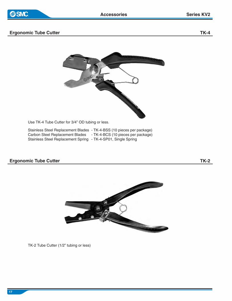
Ergonomic Tube Cutter TK-4
Series KV2
Ergonomic Tube Cutter TK-2
Stainless Steel Replacement BladesCarbon Steel Replacement BladesStainless Steel Replacement Spring
- TK-4-BSS (10 pieces per package)- TK-4-BCS (10 pieces per package)- TK-4-SP01, Single Spring
TK-2 Tube Cutter (1/2” tubing or less)
Accessories
Use TK-4 Tube Cutter for 3/4” OD tubing or less.
18
Series KV2
Cartridges
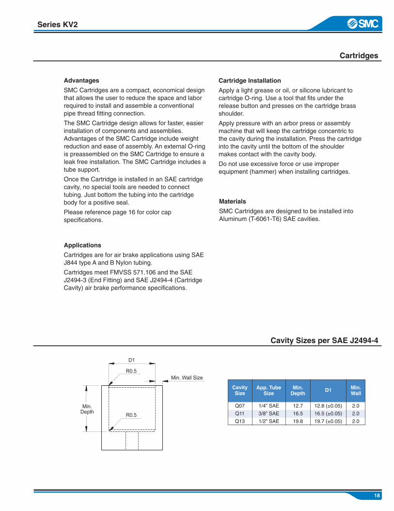
Advantages
SMC Cartridges are a compact, economical designthat allows the user to reduce the space and laborrequired to install and assemble a conventionalpipe thread fitting connection.
The SMC Cartridge design allows for faster, easierinstallation of components and assemblies.Advantages of the SMC Cartridge include weightreduction and ease of assembly. An external O-ringis preassembled on the SMC Cartridge to ensure aleak free installation. The SMC Cartridge includes atube support.
Once the Cartridge is installed in an SAE cartridgecavity, no special tools are needed to connecttubing. Just bottom the tubing into the cartridgebody for a positive seal.
Please reference page 16 for color capspecifications.
Cartridge Installation
Apply a light grease or oil, or silicone lubricant tocartridge O-ring. Use a tool that fits under therelease button and presses on the cartridge brassshoulder.
Apply pressure with an arbor press or assemblymachine that will keep the cartridge concentric tothe cavity during the installation. Press the cartridgeinto the cavity until the bottom of the shouldermakes contact with the cavity body.
Do not use excessive force or use improperequipment (hammer) when installing cartridges.
Applications
Cartridges are for air brake applications using SAEJ844 type A and B Nylon tubing.
Cartridges meet FMVSS 571.106 and the SAEJ2494-3 (End Fitting) and SAE J2494-4 (CartridgeCavity) air brake performance specifications.
Materials
SMC Cartridges are designed to be installed intoAluminum (T-6061-T6) SAE cavities.
Cavity Sizes per SAE J2494-4
1/4” SAE
3/8” SAE
1/2” SAE
12.8 (±0.05)
16.5 (±0.05)
19.7 (±0.05)
2.0
2.0
2.0
App. TubeSize
D1 Min.Wall
Q07
Q11
Q13
CavitySize
12.7
16.5
19.8
Min.Depth
19
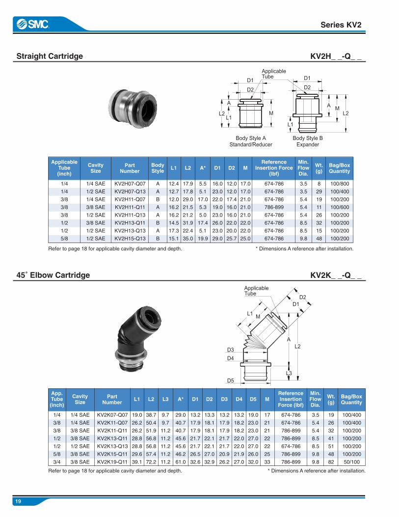
Straight Cartridge KV2H_ _-Q_ _
Series KV2
1/4
1/4
3/8
3/8
3/8
1/2
1/2
5/8
KV2H07-Q07
KV2H07-Q13
KV2H11-Q07
KV2H11-Q11
KV2H11-Q13
KV2H13-Q11
KV2H13-Q13
KV2H15-Q13
12.4
12.7
12.0
16.2
16.2
14.5
17.3
15.1
3.5
3.5
5.4
5.4
5.4
8.5
8.5
9.8
8
29
19
11
26
32
15
48
100/800
100/400
100/200
100/600
100/200
100/200
100/200
100/200
ApplicableTube(inch)
PartNumber
L1
17.9
17.8
29.0
21.5
21.2
31.9
22.4
35.0
L2
5.5
5.1
17.0
5.3
5.0
17.4
5.1
19.9
A*Min.FlowDia.
Wt.(g)
Bag/BoxQuantity
Refer to page 18 for applicable cavity diameter and depth.
1/4 SAE
1/2 SAE
1/4 SAE
3/8 SAE
1/2 SAE
3/8 SAE
1/2 SAE
1/2 SAE
CavitySize
* Dimensions A reference after installation.
16.0
23.0
22.0
19.0
23.0
26.0
23.0
29.0
D1
12.0
12.0
17.4
16.0
16.0
22.0
20.0
25.7
D2
17.0
17.0
21.0
21.0
21.0
22.0
22.0
25.0
M
45˚ Elbow Cartridge KV2K_ _-Q_ _
674-786
674-786
674-786
786-899
674-786
674-786
674-786
674-786
ReferenceInsertion Force
(lbf)
A
A
B
A
A
B
A
B
BodyStyle
1/4
3/8
3/8
1/2
1/2
5/8
3/4
KV2K07-Q07
KV2K11-Q07
KV2K11-Q11
KV2K13-Q11
KV2K13-Q13
KV2K15-Q11
KV2K19-Q11
19.0
26.2
26.2
28.8
28.8
29.6
39.1
3.5
5.4
5.4
8.5
8.5
9.8
9.8
19
26
32
41
51
48
82
100/400
100/400
100/200
100/200
100/200
100/200
50/100
App.Tube(inch)
PartNumber
L1
38.7
50.4
51.9
56.8
56.8
57.4
72.2
L2
29.0
40.7
40.7
45.6
45.6
46.2
61.0
A*Min.FlowDia.
Wt.(g)
Bag/BoxQuantity
Refer to page 18 for applicable cavity diameter and depth.
1/4 SAE
1/4 SAE
3/8 SAE
3/8 SAE
1/2 SAE
3/8 SAE
3/8 SAE
CavitySize
* Dimensions A reference after installation.
13.2
17.9
17.9
21.7
21.7
26.5
32.6
D1
13.3
18.1
18.1
22.1
22.1
27.0
32.9
D2
17
21
21
22
22
25
33
M
674-786
674-786
786-899
786-899
674-786
786-899
786-899
ReferenceInsertionForce (lbf)
9.7
9.7
11.2
11.2
11.2
11.2
11.2
L3
13.2
17.9
17.9
21.7
21.7
20.9
26.2
D3
13.2
18.2
18.2
22.0
22.0
21.9
27.0
D4
19.0
23.0
23.0
27.0
27.0
26.0
32.0
D5
Body Style AStandard/Reducer
Body Style BExpander
ApplicableTube
L2L1
L1
A
D1
D2
M
D1
D2
ML2
A
L1
D1D2
AL2
L3
D3D4
D5
M
ApplicableTube
20
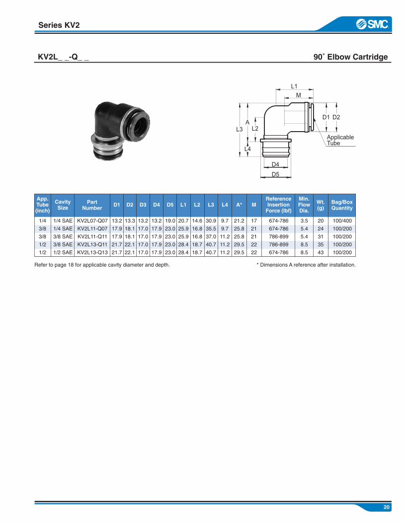
Series KV2
90˚ Elbow CartridgeKV2L_ _-Q_ _
1/4
3/8
3/8
1/2
1/2
KV2L07-Q07
KV2L11-Q07
KV2L11-Q11
KV2L13-Q11
KV2L13-Q13
20.7
25.9
25.9
28.4
28.4
3.5
5.4
5.4
8.5
8.5
20
24
31
35
43
100/400
100/200
100/200
100/200
100/200
App.Tube(inch)
PartNumber
L1
14.6
16.8
16.8
18.7
18.7
L2
21.2
25.8
25.8
29.5
29.5
A*Min.FlowDia.
Wt.(g)
Bag/BoxQuantity
Refer to page 18 for applicable cavity diameter and depth.
1/4 SAE
1/4 SAE
3/8 SAE
3/8 SAE
1/2 SAE
CavitySize
* Dimensions A reference after installation.
13.2
17.9
17.9
21.7
21.7
D1
13.3
18.1
18.1
22.1
22.1
D2
17
21
21
22
22
M
674-786
674-786
786-899
786-899
674-786
ReferenceInsertionForce (lbf)
30.9
35.5
37.0
40.7
40.7
L3
13.2
17.0
17.0
17.0
17.0
D3
13.2
17.9
17.9
17.9
17.9
D4
19.0
23.0
23.0
23.0
23.0
D5
9.7
9.7
11.2
11.2
11.2
L4
M
L1
L2L3
L4
AD1 D2
D4
D5
ApplicableTube

21
DOT/J844 Nylon Tubing TIV_ _ _-_ _
Series KV2
Recommended Operating Fluid
Maximum Operating Pressure
Recommended Operating Temperature*
Specifications
Tube O.D.
Minimum Bending Radius (mm)
Minimum Burst Pressure (psi)at 24˚C (75˚F)
Material
Air
145psi (1.0MPa)-40˚F to 140˚F (-40˚C to 60˚C)
Nylon 12 (Polyamide)
1/8”
9.4
1000
Specifications
5/32”
12.7
1200
3/16”
19.1
1200
1/4”
25.4
1200
5/16”
31.8
1000
3/8”
38.1
1000
1/2”
50.8
950
5/8”
63.5
900
3/4”
76.2
800
FMVSS 571.106
Performance requirements ofSAE J2494-3, and SAE J844 (Type A or B)
• For Use in Air Brake Systems on Heavy Duty Vehicles• All Colors are Available in All Tube Sizes
• Cold and Heat Stabilized• UV Resistant
How to Order
Tube Model
Tube Size
TIV 07 B 33
010305070911131519
1/8”5/32”3/16”1/4”5/16”3/8”1/2”5/8”3/4”
Color Indication
Length per Roll
SymbolBRGBUWYYRNSPUBRGDGRT
ColorBlackRedGreenBlueWhiteYellowOrangeNaturalSilverPurpleBrownDk. GreenGrayTan
Meters3377
153305
Conversion3377153305
====
MetersMetersMetersMeters
1082525001000
FeetFeetFeetFeet
See PackagingTable below.Not Available
in all sizesand all colors.
BRGBUWYYRNSPUBRGDGRT
BlackRedGreenBlueWhiteYellowOrangeNaturalSilverPurpleBrownDk. GreenGrayTan
Co
lor
Packaging Table
S S S S S
S
SS SS
SS
S
S
S
SSSS
SS
SSSSS
SS
SS
SS
SS
SS
SS
SS
SSS
S
S
SS S
SS
SSSS
SSS
S
SSS
S
S SS S
SSSSSSSSS
SSSSSSSSSSS
SSS
S
Tube SizeType “A” (Monowall) Type “B” (Reinforced)
TIV01 TIV03 TIV05 TIV07 TIV09 TIV11 TIV13 TIV15 TIV19 3/4”1/8” 5/32” 3/16” 1/4” 5/16” 3/8” 1/2” 5/8”
33 77 153
305
33 77 153
305
33 77 153
305
33 77 153
305
33 77 153
305
33 77 153
305
33 77 153
305
33 77 153
305
33 77 153
305Length (Meters)
S = Standard, all other length color combinations are available by special order
1/8” 5/32” 3/16” 1/4” 5/16” 3/8” 1/2” 5/8” 3/4”
Tube Sizes
*Note: Recommended operating fluid and temperature range provides best performance and longest life.Products are tested from -40˚F to 200˚F (-40˚C to 93˚C) per FMVSS 49CFR571.106.

22
Series KV2
KV2 Instructions
KV2 Torque Specifications
3/4”
1/2”
3/8”
1/4”
1/8”
Thread NPT
Stud end into metallic ports
248 to 266
248 to 266
195 to 212
106 to 124
62 to 80
Standard Thread Torque (in-lbs)
Metallic: Aluminum, zinc, stainless steel, and brass
Insert the KV2series fitting intoport and rotateuntil hand tight.
Using approvedassembly method,tighten KV2 fitting toSMC recommendedtorque specifications.(see below)
Rotate KV2series fitting todesired location.
Insert DOT approvedtubing into the KV2series fitting until thetube bottoms out.
Gently pull back ontubing to engage thegripping teeth intothe tube.
Installation Features
RemovalRelease systemair pressure fromair tanks prior toremoving any KV2fittings or DOTtubing.
Push in guide toremove tube fromKV2 series fitting.
Depress and holdthe release buttonagainst the fittingbody, then removetubing.
Remove KV2 seriesfitting from the fittingport with approvedwrench.
Caution

23
Important Information
Series KV2
24
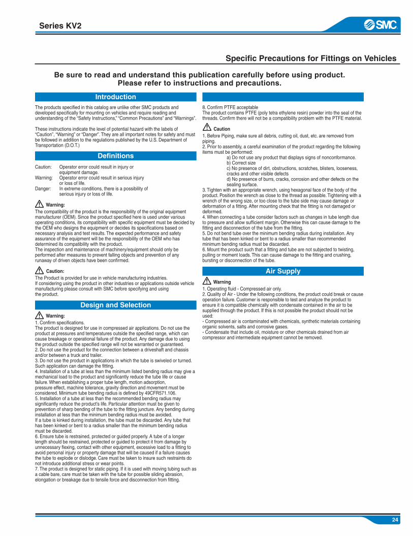
Series KV2
Specific Precautions for Fittings on Vehicles

25
Series KV2
Specific Precautions for Fittings on Vehicles (Continued)
26
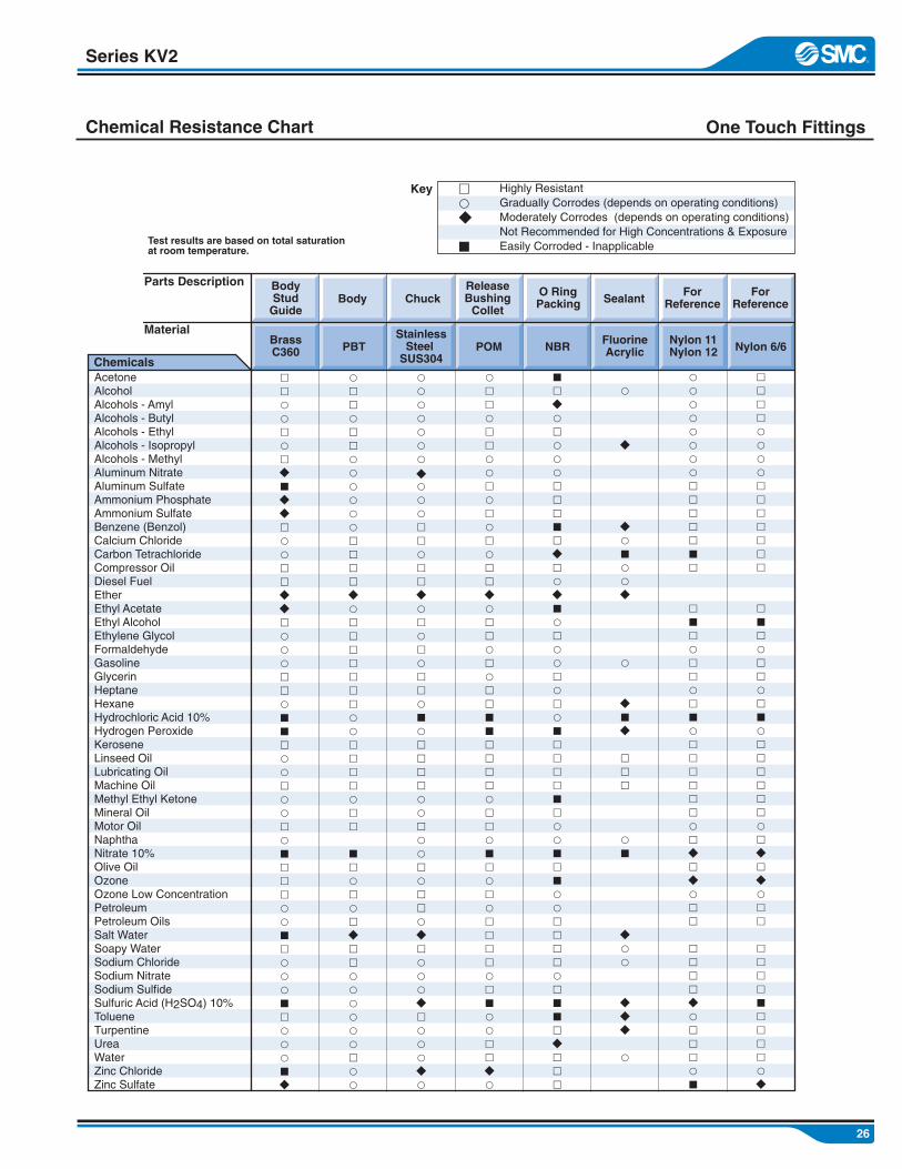
Chemical Resistance Chart
Series KV2
One Touch Fittings
mpR
M
AcetoneAlcoholAlcohols - AmylAlcohols - ButylAlcohols - EthylAlcohols - IsopropylAlcohols - MethylAluminum NitrateAluminum SulfateAmmonium PhosphateAmmonium SulfateBenzene (Benzol)Calcium ChlorideCarbon TetrachlorideCompressor OilDiesel FuelEtherEthyl AcetateEthyl AlcoholEthylene GlycolFormaldehydeGasolineGlycerinHeptaneHexaneHydrochloric Acid 10%Hydrogen PeroxideKeroseneLinseed OilLubricating OilMachine OilMethyl Ethyl KetoneMineral OilMotor Oil NaphthaNitrate 10%Olive Oil OzoneOzone Low ConcentrationPetroleumPetroleum OilsSalt WaterSoapy WaterSodium ChlorideSodium NitrateSodium SulfideSulfuric Acid (H2SO4) 10%TolueneTurpentineUreaWaterZinc ChlorideZinc Sulfate
mmppmpmRMRRmppmmRRmpppmmpMMmppmppmpMmmmppMmpppMmpppMR
pmmpmmppppppmmmmRpmmmmmmmppmmmmpmm
MmpmpmRmmppppppmpp
pppppppRpppmmpmmRpmpmpmmpMpmmmmppmppmpmmpRmpppRmpppRp
pmmpmmppmpmpmpmmRpmmpmpmmMMmmmmpmmpMmpmpmmmmpmMppmmRp
MmRpmpppmmmMmRmpRMpmppmpmpMmmmmMmppMmMppmmmmpmMMmRmmm
p
R
RpMppR
p
RMR
mmm
pM
Rpp
RRR
p
ppppppppmmmmmMm
mMmpmmpmMpmmmmmmpmRmRpmm
mmmmRpmmmpM
mmmmppppmmmmmmm
mMmpmmpmMpmmmmmmpmRmRpmm
mmmmMmmmmpR
Key
Parts Description
Material
Chemicals
BrassC360
FluorineAcrylic
Nylon 11Nylon 12
StainlessSteel
SUS304PBT Nylon 6/6POM NBR
BodyStud
GuideBody Chuck
ReleaseBushing
Collet
O RingPacking Sealant
ForReference
ForReference
Test results are based on total saturationat room temperature.
Highly ResistantGradually Corrodes (depends on operating conditions)Moderately Corrodes (depends on operating conditions)Not Recommended for High Concentrations & ExposureEasily Corroded - Inapplicable

27
Series KV2

28
Series KV2
Return Policy
KV2 Warranty:SMC Corporation of America (SMC) products listed for sale in this catalog are warranted to be free from defects in materials and workmanship for a period of one (1) year after the date of purchase (the “Warranty Period”).Provided purchaser installs, operates andmaintains the products in accordance with all SMC application guidelines and customary industry practices.
Notice of Warranty Claims:If purchaser determines a product has a defectin materials or workmanship prior to expirationof the Warranty Period, and desires to make awarranty claim, purchaser shall return such product (along with the original purchase ordernumber) to the nearest SMC sales office or authorized distributor, postage or delivery charges prepaid. Any returned product must bereceived by SMC prior to expiration of the Warranty Period to make a valid warranty claim. The back page of this brochure lists current SMC addresses for product returns.
Response to Claims and Remedies:All products timely returned to SMC may be inspected, tested or otherwise examined bySMC in its sole discretion, and SMC shallforward to purchaser written notice (via facsimile or otherwise) of such determination within thirty (30) days following SMC’s receipt of product. In the event SMC determines aproduct is defective, SMC shall at purchaser’s option: (i) replace the defective product free ofcharge; or (ii) provide a credit in the amount of the original purchase price to purchaser against future product purchases from SMC.Product replacement or purchase price creditshall be purchaser’s sole legal remedy underthis warranty.
Limited Warranty: Other than the express warranty described above, there are not express or implied warranties made by SMC with the respect to the products in this brochure. The warranty given herein expressly EXCLUDES any warranty of merchantability or fitness for a particular purpose, and there are not warranties which extend beyond the description on the face hereof. To the fullest extent permitted by law, in no event shall SMC be responsible or liablefor any incidental, consequential, or other damages, claims or costs arising from any product defect. The warranty provided herein shall begoverned by and construed in accordance with the laws rules thereof, and any legal proceeding related to the products or this warranty shall befiled in a federal or state court of competentjurisdiction located in Hamilton County, Indiana.
Additional Information: Questions regarding SMC products and warranty information may be directed to purchaser’s sales representative at representative’s current place of business, or to SMC Claims Department in writing at the following address:
SMC Corporation of AmericaATTN: Claims Department 10100 SMC BoulevardNoblesville, IN 46060
No response to any inquiry shall be interpreted to restrict, expand or modify the warranty described herein.
29
Notes
Series KV2

30
Series KV2
Notes

31
Notes
Series KV2