Series RGX ANTI - SURGE AIR RELEASE & VACUUM BREAK VALVES … RGX Sewer.pdf · r series rgx "anti -...
40
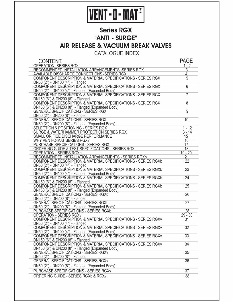
R Series RGX "ANTI - SURGE" AIR RELEASE & VACUUM BREAK VALVES CONTENT PAGE CATALOGUE INDEX OPERATION -SERIES RGX 1-2 RECOMMENDED INSTALLATION ARRANGEMENTS -SERIES RGX 3 AVAILABLE DISCHARGE CONNECTIONS -SERIES RGX 4 COMPONENT DESCRIPTION & MATERIAL SPECIFICATIONS - SERIES RGX 5 DN50 (2") - DN100 (4") - Flanged COMPONENT DESCRIPTION & MATERIAL SPECIFICATIONS - SERIES RGX 6 DN50 (2") - DN100 (4") - Flanged (Expanded Body) COMPONENT DESCRIPTION & MATERIAL SPECIFICATIONS - SERIES RGX 7 DN150 (6") & DN200 (8") - Flanged COMPONENT DESCRIPTION & MATERIAL SPECIFICATIONS - SERIES RGX 8 DN150 (6") & DN200 (8") - Flanged (Expanded Body) GENERAL SPECIFICATIONS - SERIES RGX 9 DN50 (2") - DN200 (8") - Flanged GENERAL SPECIFICATIONS - SERIES RGX 10 DN50 (2") - DN200 (8") - Flanged (Expanded Body) SELECTION & POSITIONING - SERIES RGX 11 - 12 SURGE & WATERHAMMER PROTECTION SERIES RGX 13 - 14 SMALL ORIFICE DISCHARGE PERFORMANCE 15 WHY VENT-O-MAT SERIES RGX? 16 PURCHASE SPECIFICATIONS - SERIES RGX 17 ORDERING GUIDE & TEST SPECIFICATIONS - SERIES RGX 18 OPERATION - SERIES RGXb 19 - 20 RECOMMENDED INSTALLATION ARRANGEMENTS - SERIES RGXb 21 COMPONENT DESCRIPTION & MATERIAL SPECIFICATIONS - SERIES RGXb 22 DN50 (2") - DN100 (4") - Flanged COMPONENT DESCRIPTION & MATERIAL SPECIFICATIONS - SERIES RGXb 23 DN50 (2") - DN100 (4") - Flanged (Expanded Body) COMPONENT DESCRIPTION & MATERIAL SPECIFICATIONS - SERIES RGXb 24 DN150 (6") & DN200 (8") - Flanged COMPONENT DESCRIPTION & MATERIAL SPECIFICATIONS - SERIES RGXb 25 DN150 (6") & DN200 (8") - Flanged (Expanded Body) GENERAL SPECIFICATIONS - SERIES RGXb 26 DN50 (2") - DN200 (8") - Flanged GENERAL SPECIFICATIONS - SERIES RGXb 27 DN50 (2") - DN200 (8") - Flanged (Expanded Body) PURCHASE SPECIFICATIONS - SERIES RGXb 28 OPERATION - SERIES RGXv 29 - 30 COMPONENT DESCRIPTION & MATERIAL SPECIFICATIONS - SERIES RGXv 31 DN50 (2") - DN100 (4") - Flanged COMPONENT DESCRIPTION & MATERIAL SPECIFICATIONS - SERIES RGXv 32 DN50 (2") - DN100 (4") - Flanged (Expanded Body) COMPONENT DESCRIPTION & MATERIAL SPECIFICATIONS - SERIES RGXv 33 DN150 (6") & DN200 (8") - Flanged COMPONENT DESCRIPTION & MATERIAL SPECIFICATIONS - SERIES RGXv 34 DN150 (6") & DN200 (8") - Flanged (Expanded Body) GENERAL SPECIFICATIONS - SERIES RGXv 35 DN50 (2 - DN200 (8 - Flanged GENERAL SPECIFICATIONS - SERIES RGXv 36 DN50 (2 - DN200 (8 - Flanged (Expanded Body) PURCHASE SPECIFICATIONS - SERIES RGXv 37 ORDERING GUIDE - SERIES RGXb & RGXv 38 ") ") ") ")
Transcript of Series RGX ANTI - SURGE AIR RELEASE & VACUUM BREAK VALVES … RGX Sewer.pdf · r series rgx "anti -...
R
Series RGX
"ANTI - SURGE"
AIR RELEASE & VACUUM BREAK VALVES
CONTENT PAGE
CATALOGUE INDEX
OPERATION -SERIES RGX 1 - 2RECOMMENDED INSTALLATION ARRANGEMENTS -SERIES RGX 3AVAILABLE DISCHARGE CONNECTIONS -SERIES RGX 4COMPONENT DESCRIPTION & MATERIAL SPECIFICATIONS - SERIES RGX 5DN50 (2") - DN100 (4") - FlangedCOMPONENT DESCRIPTION & MATERIAL SPECIFICATIONS - SERIES RGX 6DN50 (2") - DN100 (4") - Flanged (Expanded Body)COMPONENT DESCRIPTION & MATERIAL SPECIFICATIONS - SERIES RGX 7DN150 (6") & DN200 (8") - FlangedCOMPONENT DESCRIPTION & MATERIAL SPECIFICATIONS - SERIES RGX 8DN150 (6") & DN200 (8") - Flanged (Expanded Body)GENERAL SPECIFICATIONS - SERIES RGX 9DN50 (2") - DN200 (8") - FlangedGENERAL SPECIFICATIONS - SERIES RGX 10DN50 (2") - DN200 (8") - Flanged (Expanded Body)SELECTION & POSITIONING - SERIES RGX 11 - 12SURGE & WATERHAMMER PROTECTION SERIES RGX 13 - 14SMALL ORIFICE DISCHARGE PERFORMANCE 15WHY VENT-O-MAT SERIES RGX? 16PURCHASE SPECIFICATIONS - SERIES RGX 17ORDERING GUIDE & TEST SPECIFICATIONS - SERIES RGX 18OPERATION - SERIES RGXb 19 - 20RECOMMENDED INSTALLATION ARRANGEMENTS - SERIES RGXb 21COMPONENT DESCRIPTION & MATERIAL SPECIFICATIONS - SERIES RGXb 22DN50 (2") - DN100 (4") - FlangedCOMPONENT DESCRIPTION & MATERIAL SPECIFICATIONS - SERIES RGXb 23DN50 (2") - DN100 (4") - Flanged (Expanded Body)COMPONENT DESCRIPTION & MATERIAL SPECIFICATIONS - SERIES RGXb 24DN150 (6") & DN200 (8") - FlangedCOMPONENT DESCRIPTION & MATERIAL SPECIFICATIONS - SERIES RGXb 25DN150 (6") & DN200 (8") - Flanged (Expanded Body)GENERAL SPECIFICATIONS - SERIES RGXb 26DN50 (2") - DN200 (8") - FlangedGENERAL SPECIFICATIONS - SERIES RGXb 27DN50 (2") - DN200 (8") - Flanged (Expanded Body)PURCHASE SPECIFICATIONS - SERIES RGXb 28OPERATION - SERIES RGXv 29 - 30COMPONENT DESCRIPTION & MATERIAL SPECIFICATIONS - SERIES RGXv 31DN50 (2") - DN100 (4") - FlangedCOMPONENT DESCRIPTION & MATERIAL SPECIFICATIONS - SERIES RGXv 32DN50 (2") - DN100 (4") - Flanged (Expanded Body)COMPONENT DESCRIPTION & MATERIAL SPECIFICATIONS - SERIES RGXv 33DN150 (6") & DN200 (8") - FlangedCOMPONENT DESCRIPTION & MATERIAL SPECIFICATIONS - SERIES RGXv 34DN150 (6") & DN200 (8") - Flanged (Expanded Body)GENERAL SPECIFICATIONS - SERIES RGXv 35DN50 (2 - DN200 (8 - FlangedGENERAL SPECIFICATIONS - SERIES RGXv 36DN50 (2 - DN200 (8 - Flanged (Expanded Body)PURCHASE SPECIFICATIONS - SERIES RGXv 37ORDERING GUIDE - SERIES RGXb & RGXv 38
") ")
") ")
R
Series RGX
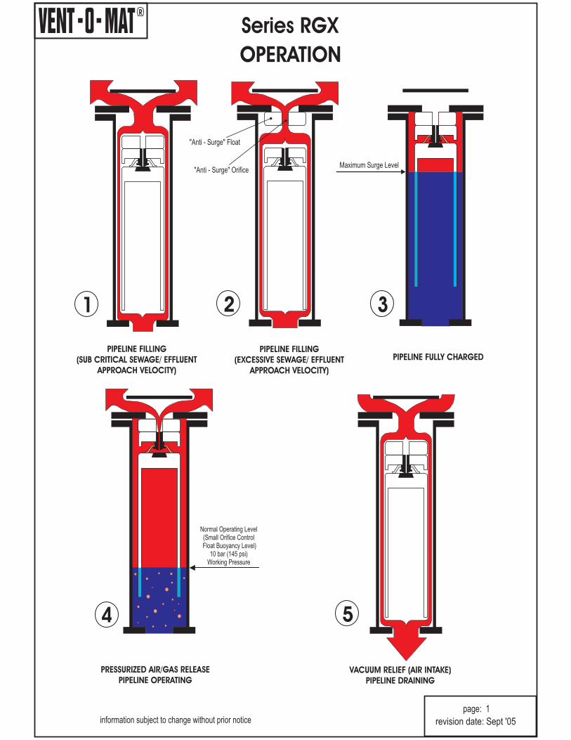
OPERATION
PRESSURIZED AIR/GAS RELEASE
PIPELINE OPERATINGVACUUM RELIEF (AIR INTAKE)
PIPELINE DRAINING
PIPELINE FILLING
(SUB CRITICAL SEWAGE/ EFFLUENT
APPROACH VELOCITY)
PIPELINE FILLING
(EXCESSIVE SEWAGE/ EFFLUENT
APPROACH VELOCITY)
PIPELINE FULLY CHARGED
1 2 3
54
Normal Operating Level(Small Orifice ControlFloat Buoyancy Level)
10 bar (145 psi)Working Pressure
Maximum Surge Level"Anti - Surge" Orifice
"Anti - Surge" Float
information subject to change without prior noticepage: 1
revision date: Sept '05

R
Series RGX
OPERATION
A) VENTING OF A FILLING PIPELINE:
B) SURGE ALLEVIATION - PIPELINE PRESSURIZED:
Attention is drawn to Pre Notes (A) and (B) above.
NO FLUSHING CONNECTIONS ARE NECESSARY.
NO FLUSHING CONNECTIONS ARE NECESSARY.
NO FLUSHING CONNECTIONS ARE
NECESSARY.
*NOTE:
The operation of a conventional sewage air release valve is such that fast approaching sewage/effluent is almost instantaneouslyhalted by the valve's closure. Consequently a transient pressure rise or shock of potentially damaging proportions can be generated ina pipeline system, even at normal filling rates.
In addition to venting through the Large Orifice when sewage/ effluent approach velocities are sub critical, the Vent -O- Mat seriesRGX sewage air release valves feature an automatic "Anti - Surge" Orifice device that serves to decelerate sewage/ effluentapproaching at excessive speed, thereby limiting pressure rise in the pipeline.
In instances where a pipeline experiences liquid column separation due to pump stoppage, high shock pressures can be g e n e r a t e dwhen the separated column rejoins.
The Vent -O- Mat series RGX takes in air through the unobstructed large orifice when column separation occurs, but controls thedischarge of air/gas through the "Anti-Surge" Orifice as the separated column commences to rejoin. The rejoining impact velocity isthereby sufficiently reduced to prevent an unacceptably high surge pressure in the system. In the same way the series RGX valve
prevents high surge pressures resulting from liquid oscillation in a pipeline.
Air/gas flows through the annular area around the control float assembly and to atmosphere through the large orifice.
In reaction to an increase in air/gas flow, the "Anti - Surge" float closes the large orifice and air/gas is forced through the "Anti - Surge"Orifice resulting in a deceleration of the approaching liquid due to the resistance of rising air/gas pressure in the valve.
Sewage/effluent has entered the the valve chamber and buoyed the floats to close both the large and the small orifice. The design'scompression/ volume relationship prevents the media from ever exceeding the maximum surge level indicated in diagram 3. Theresultant sewage/ effluent free area protects against the fouling of the orifice seals by solids or high viscous substances - for this reason
The volume of disentrained air/gas increases in the valve and displaces the sewage/effluent to the lower, normal operating level (smallorifice control float buoyancy level). Any additional lowering of the sewage/effluent level, as would occur when more air/gas enters thevalve, will result in the control float dropping away from the small orifice through which pressurized air/gas is then being discharged toatmosphere.
The control float will close the small orifice when sufficient air/gas has been released to restore the sewage effluent to the normaloperating level.
The considerable sewage/effluent free area obviates the possibility of leaks that could otherwise be caused by solids entering thesealing areas - for this reason
When the internal pipeline pressure reduces to atmosphere the "Anti - Surge " mechanism and control float assembly drops, opens thelarge orifice and allows the pipeline to take in air to displace the draining media so as to prevent undesirable low negativepressure*.The hollow, smooth side float design discourages adherence of solids and viscous substances which, therefore, tend towithdraw from the valve into the pipeline when draining occurs - for this reason
Negative pressure values are dependant on valve size selection.
1. PIPELINE FILLING (SUB CRITICALSEWAGE/ EFFLUENT APPROACHVELOCITY)
2. PIPELINE FILLING (EXCESSIVE SEWAGE/ EFFLUENT APPROACHVELOCITY)
3. PIPELINE FULLY CHARGED
4. PRESSURIZEDAIR/GASRELEASE - PIPELINE OPERATING
5. VACUUM RELIEF (AIR INTAKE) - PIPELINE DRAINING
PRE NOTES:
information subject to change without prior noticepage: 2
revision date: Sept '05
R
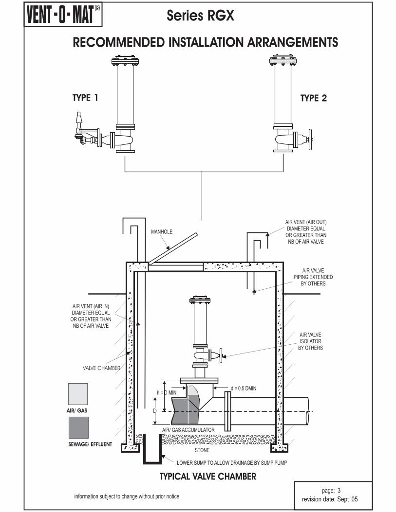
RECOMMENDED INSTALLATION ARRANGEMENTS
Series RGX
information subject to change without prior noticepage: 3
AIR VENT (AIR IN)DIAMETER EQUAL
OR GREATER THANNB OF AIR VALVE
AIR VENT (AIR OUT)DIAMETER EQUAL
OR GREATER THANNB OF AIR VALVE
AIR VALVEPIPING EXTENDED
BY OTHERS
AIR VALVEISOLATOR
BY OTHERS
MANHOLE
STONE
AIR/ GAS
SEWAGE/ EFFLUENT
LOWER SUMP TO ALLOW DRAINAGE BY SUMP PUMP
VALVE CHAMBER
AIR/ GAS ACCUMULATOR
TYPICAL VALVE CHAMBER
d = 0.5 DMIN.h = D MIN.
D
TYPE 1 TYPE 2
revision date: Sept '05

R
AVAILABLE DISCHARGE CONNECTIONS50 ( 200 (2") TO 8")
250 (10") & 300 (12") VALVES AVAILABLE ON REQUEST
Series RGX
information subject to change without prior notice
page: 4
Standard DischargeConnection. ScreenMesh On Outlet.DN50 (2"), DN80 (3"), DN100 (4"),DN150 (6") & DN200 (8")
Swivel Flange OutletConnection.*
Flanged Trophy InletConnection forDN250 (10”) & DN300 (12”)Valves Only
*NOTE:Discharge Connections Are Equal To Valve Pressure Rating
Screwed BSP/NPTInlet Connection.DN50 (2") Valves Only.
STANDARDS
StuddedInlet Connection.DN80 (3"), DN100 (4 ,DN150 (6 & DN200 (8Valves Only.
")") ")
SPECIAL ORDERS
revision date: Sept '05
R
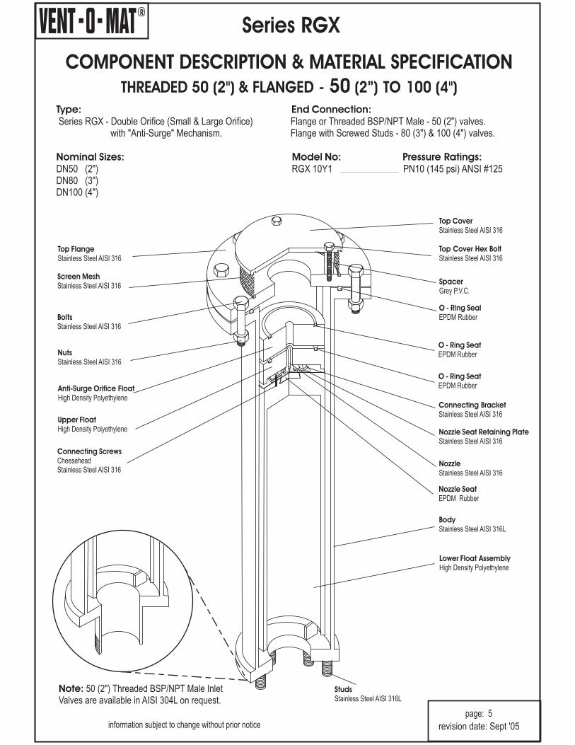
COMPONENT DESCRIPTION & MATERIAL SPECIFICATION
50- (2”) TO 100 (4THREADED 50 (2") & FLANGED ")
Type: End Connection:
Nominal Sizes: Model No: Pressure Ratings:
Series RGX - Double Orifice (Small & Large Orifice) Flange or Threaded BSP/NPT Male - 50 (2 valves.with "Anti-Surge" Mechanism.
DN50 (2") RGX 10Y1 PN10 (145 psi) ANSI #125DN80 (3
")Flange with Screwed Studs - 80 (3") & 100 (4") valves.
")DN100 (4")
Series RGX
information subject to change without prior noticepage: 5
Top CoverStainless Steel AISI 316
SpacerGrey P.V.C.
Top Cover Hex BoltStainless Steel AISI 316
O - Ring SealEPDM Rubber
Top FlangeStainless Steel AISI 316
Screen MeshStainless Steel AISI 316
BoltsStainless Steel AISI 316
Upper FloatHigh Density Polyethylene
NozzleStainless Steel AISI 316
Nozzle SeatEPDM Rubber
NutsStainless Steel AISI 316
Connecting BracketStainless Steel AISI 316
Anti-Surge Orifice FloatHigh Density Polyethylene
O - Ring SeatEPDM Rubber
Nozzle Seat Retaining PlateStainless Steel AISI 316
Lower Float AssemblyHigh Density Polyethylene
StudsStainless Steel AISI 316L
Connecting ScrewsCheeseheadStainless Steel AISI 316
BodyStainless Steel AISI 316L
Note: 50 (2Valves are available in AISI 304L on request.
") Threaded BSP/NPT Male Inlet
revision date: Sept '05
O - Ring SeatEPDM Rubber
R
Top CoverStainless Steel AISI 316
SpacerGrey P.V.C.
Top Cover Hex BoltStainless Steel AISI 316
O - Ring SealEPDM Rubber
Top FlangeStainless Steel AISI 316
Screen MeshStainless Steel AISI 316
BoltsStainless Steel AISI 316
Upper FloatHigh Density Polyethylene
NozzleStainless Steel AISI 316
Nozzle SeatEPDM Rubber
NutsStainless Steel AISI 316
Connecting BracketStainless Steel AISI 316
Anti-Surge Orifice FloatHigh Density Polyethylene
O - Ring SeatEPDM Rubber
Nozzle Seat Retaining PlateStainless Steel AISI 316
Lower Float AssemblyHigh Density Polyethylene
StudsStainless Steel AISI 316L
Connecting ScrewsCheeseheadStainless Steel AISI 316
BodyStainless Steel AISI 316L
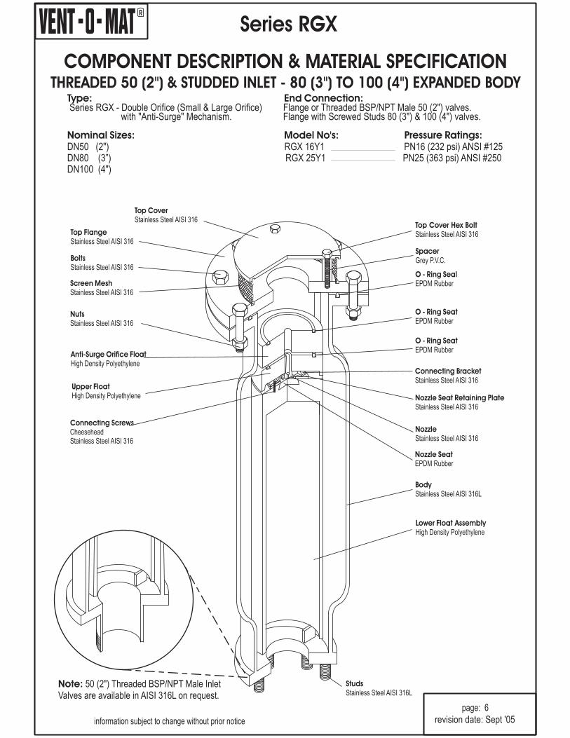
COMPONENT DESCRIPTION & MATERIAL SPECIFICATIONTHREADED 50 (2 STUDDED INLET - 80 (3 TO 100 (4") EXPANDED BODY") & ")
Series RGX
Type: End Connection:
Nominal Sizes: Model No's: Pressure Ratings:
Series RGX - Double Orifice (Small & Large Orifice) Flange or Threaded BSP/NPT Male 50 (2 valves.with "Anti-Surge" Mechanism.
DN50 (2
DN100 (4")
")Flange with Screwed Studs 80 (3") & 100 (4") valves.
") RGX 16Y1 PN16 (232 psi) ANSI #125DN80 (3”) RGX 25Y1 PN25 (363 psi) ANSI #250
page: 6
information subject to change without prior notice revision date: Sept '05
O - Ring SeatEPDM Rubber
Note: 50 (2Valves are available in AISI 316L on request.
") Threaded BSP/NPT Male Inlet
R
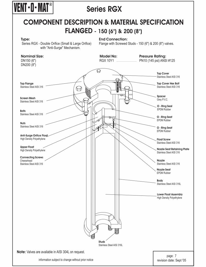
COMPONENT DESCRIPTION & MATERIAL SPECIFICATION
FLANGED - 6") & 8150 ( 200 ( ")
Type: End Connection:
Nominal Size: Model No: Pressure Rating:
Series RGX - Double Orifice (Small & Large Orifice) Flange with Screwed Studs - 150 (6 & 200 (8 valves.with "Anti-Surge" Mechanism.
DN150 (6") RGX 10Y1 PN10 (145 psi) ANSI #125DN200 (8
") ")
")
Series RGX
information subject to change without prior noticepage: 7
Top CoverStainless Steel AISI 316
SpacerGrey P.V.C.
Top Cover Hex BoltStainless Steel AISI 316
O - Ring SealEPDM Rubber
Top FlangeStainless Steel AISI 316
Screen MeshStainless Steel AISI 316
BoltsStainless Steel AISI 316
Upper FloatHigh Density Polyethylene
NozzleStainless Steel AISI 316
Nozzle SeatEPDM Rubber
NutsStainless Steel AISI 316
Float ScrewStainless Steel AISI 316
Anti-Surge Orifice FloatHigh Density Polyethylene
Nozzle Seat Retaining PlateStainless Steel AISI 316
Lower Float AssemblyHigh Density Polyethylene
StudsStainless Steel AISI 316L
Connecting ScrewsCheeseheadStainless Steel AISI 316
BodyStainless Steel AISI 316L
Note: Valves are available in AISI 304L on request.
revision date: Sept '05
O - Ring SeatEPDM Rubber
O - Ring SeatEPDM Rubber

R
Top CoverStainless Steel AISI 316
SpacerGrey P.V.C.
Top Cover Hex BoltStainless Steel AISI 316
O - Ring SealEPDM Rubber
Top FlangeStainless Steel AISI 316
Screen MeshStainless Steel AISI 316
BoltsStainless Steel AISI 316
Upper FloatHigh Density Polyethylene
NozzleStainless Steel AISI 316
Nozzle SeatEPDM Rubber
NutsStainless Steel AISI 316
Float ScrewStainless Steel AISI 316
Anti-Surge Orifice FloatHigh Density Polyethylene
O - Ring SeatEPDM Rubber
Nozzle Seat Retaining PlateStainless Steel AISI 316
Lower Float AssemblyHigh Density Polyethylene
StudsStainless Steel AISI 316L
Connecting ScrewsCheeseheadStainless Steel AISI 316
BodyStainless Steel AISI 316L
COMPONENT DESCRIPTION & MATERIAL SPECIFICATIONFLANGED - 6") & 200 (8") EXPANDED BODY150 (
Series RGX
Type: End Connection:
Nominal Sizes: Model No's: Pressure Ratings:
Series RGX - Double Orifice (Small & Large Orifice) Flange with Screwed Studs - 150 (6 & 200 (8 valves.with "Anti-Surge" Mechanism.
150 (6") RGX 16Y1 PN16 (232 psi) ANSI # 125
200 (8") RGX 25Y1 PN25 (363 psi) ANSI # 250
") ")
page: 8
information subject to change without prior notice
Note: Valves are available in AISI 304L on request.
revision date: Sept '05
O - Ring SeatEPDM Rubber
R
Series RGX
Type:
End Connection:
Nominal Sizes:
Model No's: Pressure Ratings bar (psi):
Operating Pressure Range - bar (psi):
Function:
Valve Selection:-
Materials of Construction:-
Installation:-
Standard Factory Tests:
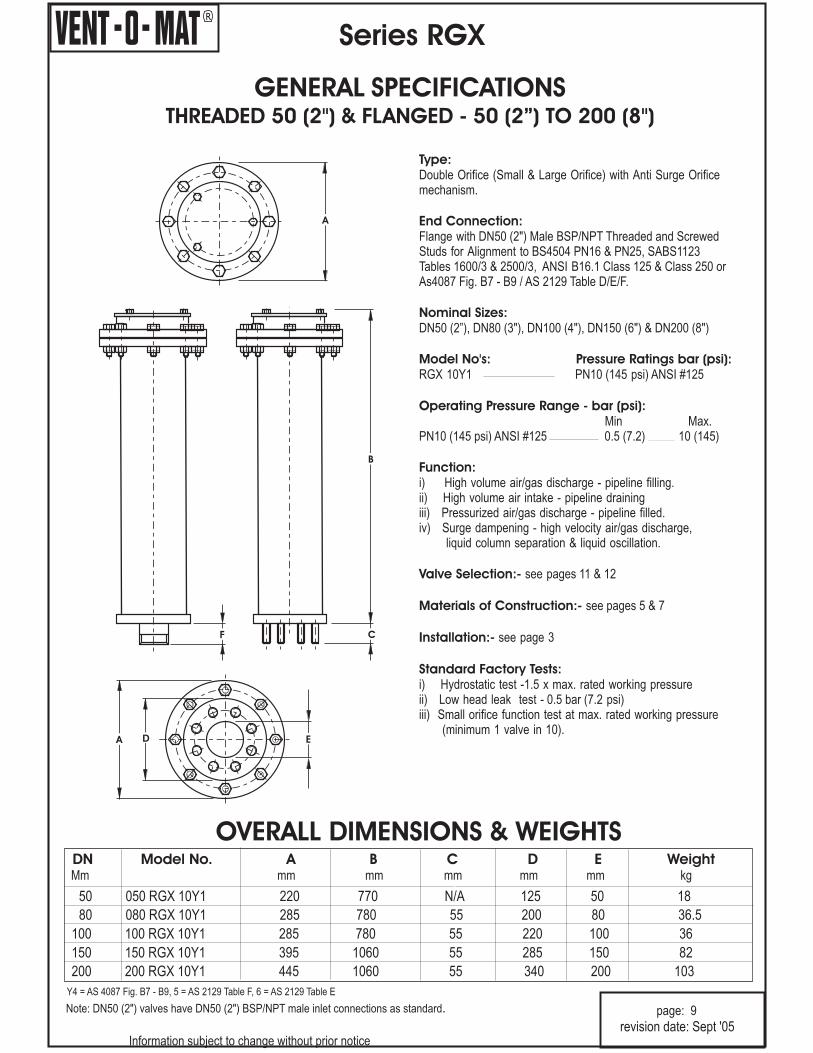
Double Orifice (Small & Large Orifice) with Anti Surge Orificemechanism.
Flange with DN50 (2 Male BSP/NPT Threaded and Screwed
DN50 (2”), DN80 (3"), DN100 (4"), DN150 (6") & DN200 (8")
RGX 10Y1 PN10 (145 psi) ANSI #125
Min Max.PN10 (145 psi) ANSI #125 0.5 (7.2) 10 (145)
i) High volume air/gas discharge - pipeline filling.ii) High volume air intake - pipeline drainingiii) Pressurized air/gas discharge - pipeline filled.iv) Surge dampening - high velocity air/gas discharge,
liquid column separation & liquid oscillation.
see pages 11 & 12
see pages 5 & 7
see page 3
i) Hydrostatic test -1.5 x max. rated working pressureii) Low head leak test - 0.5 bar (7.2 psi)iii) Small orifice function test at max. rated working pressure
(minimum 1 valve in 10).
")Studs for Alignment to BS4504 PN16 & PN25, SABS1123Tables 1600/3 & 2500/3, ANSI B16.1 Class 125 & Class 250 orAs4087 Fig. B7 - B9 / AS 2129 Table D/E/F.
GENERAL SPECIFICATIONSTHREADED 50 (2 FLANGED - 50 (2”) TO 200 (8") & ")
Information subject to change without prior notice
page: 9
A
D EA
Note: DN50 (2") valves have DN50 (2") BSP/NPT male inlet connections as standard.
OVERALL DIMENSIONS & WEIGHTS
C
B
F
revision date: Sept '05
80 080 RGX 10Y1 285 780 55 200 80 36.5
100 100 RGX 10Y1 285 780 55 220 100 36
150 150 RGX 10Y1 395 1060 55 285 150 82
200 200 RGX 10Y1 445 1060 55 340 200 103
DN Model No. A B C D E WeightMm mm mm mm mm mm kg
50 050 RGX 10Y1 220 770 N/A 125 50 18
Y4 = AS 4087 Fig. B7 - B9, 5 = AS 2129 Table F, 6 = AS 2129 Table E

R
Series RGX
Type:
End Connection:
Nominal Sizes:
Model No's: Pressure Ratings bar (psi):
Operating Pressure Range - bar (psi):
Function:
Valve Selection:-
Materials of Construction:-
Installation:-
Standard Factory Tests:
Double Orifice (Small & Large Orifice) with Anti Surge Orificemechanism.
DN50 (2"), DN80 (3"), DN100 (4"), DN150 (6") & DN200 (8")
.PN16 (232 psi) ANSI #125 0.5 (7.2) 16 (232)PN25 (363 psi) ANSI #250
i) High volume air/gas discharge - pipeline filling.ii) High volume air intake - pipeline drainingiii) Pressurized air/gas discharge - pipeline filled.iv) Surge dampening - high velocity air/gas discharge,
liquid column separation & liquid oscillation.
see pages 11 & 12
see pages 6 & 8
see page 3
i) Hydrostatic test -1.5 x max. rated working pressureii) Low head leak test - 0.5 bar (7.2 psi)iii) Small orifice function test at max. rated working pressure
(minimum 1 valve in 10).
Min Max
Flange with DN50 (2") Male BSP/NPT Threaded and ScrewedStuds for Alignment to BS4504 PN16 & PN25, SABS1123Tables 1600/3 & 2500/3, ANSI B16.1 Class 125 & Class 250or As4087 Fig. B7 - B9 / AS 2129 Table D/E/F.
RGX 16Y1 PN16 (232 psi) ANSI #125RGX 25Y1 PN25 (363 psi) ANSI #250
0.5 (7.2) 16 (363)
OVERALL DIMENSIONS & WEIGHTS
GENERAL SPECIFICATIONSTHREADED 50 (2 & FLANGED - 50 (2”) TO 200 (8") ") EXPANDED BODY
information subject to change without prior notice
page: 10
A
D EA
Note: DN50 (2") valves have Dn50 (2") BSP/NPT male inlet connections as standard.
F
B
C
revision date: Sept '05
80 080 RGX 16Y1 285 780 55 200 80 37.5
100 100 RGX 16Y1 285 780 55 220 100 37
150 150 RGX 16Y1 395 1060 55 285 150 84.5
200 200 RGX 16Y1 445 1060 55 340 200 105.5
DN Model No. A B C D E Weightmm mm mm mm mm mm kg
50 050 RGX 16Y1 220 770 N/A 125 50 21
80 080 RGX 25Y1 285 780 55 200 80 37.5
100 100 RGX 25Y1 285 780 55 220 100 37
150 150 RGX 25Y1 395 1060 55 285 150 84.5
200 200 RGX 25Y1 445 1060 55 340 200 105.5
50 050 RGX 25Y1 220 770 N/A 125 50 21
Y4 = AS 4087 Fig. B7 - B9, 5 = AS 2129 Table F, 6 = AS 2129 Table E
R
Series RGX
SELECTION & POSITIONING
information subject to change without prior noticepage: 11
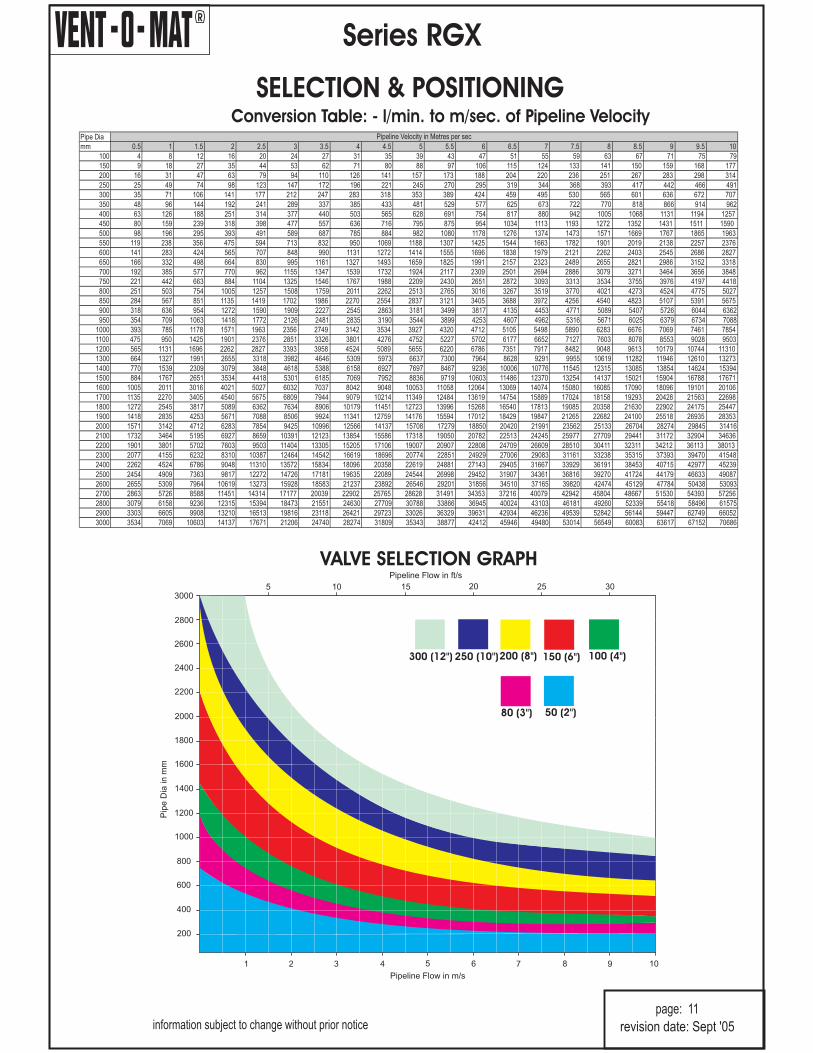
Conversion Table: - l/min. to m/sec. of Pipeline Velocity
VALVE SELECTION GRAPH
300 (12") 200 (8")
80 (3") 50 (2")
150 (6") 100 (4")250 (10")
revision date: Sept '05
Pip
eD
iain
mm
3000
2800
2600
2400
2200
2000
1800
1600
1400
1200
1000
800
600
400
200
Pipeline Flow in m/s
1 2 3 4 5 6 7 8 9 10
Pipeline Flow in ft/s
5 10 15 20 25 30
Pipe Dia
mm 0.5 1 1.5 2 2.5 3 3.5 4 4.5 5 5.5 6 6.5 7 7.5 8 8.5 9 9.5 10
100 4 8 12 16 20 24 27 31 35 39 43 47 51 55 59 63 67 71 75 79
150 9 18 27 35 44 53 62 71 80 88 97 106 115 124 133 141 150 159 168 177
200 16 31 47 63 79 94 110 126 141 157 173 188 204 220 236 251 267 283 298 314
250 25 49 74 98 123 147 172 196 221 245 270 295 319 344 368 393 417 442 466 491
300 35 71 106 141 177 212 247 283 318 353 389 424 459 495 530 565 601 636 672 707
350 48 96 144 192 241 289 337 385 433 481 529 577 625 673 722 770 818 866 914 962
400 63 126 188 251 314 377 440 503 565 628 691 754 817 880 942 1005 1068 1131 1194 1257
450 80 159 239 318 398 477 557 636 716 795 875 954 1034 1113 1193 1272 1352 1431 1511 1590
500 98 196 295 393 491 589 687 785 884 982 1080 1178 1276 1374 1473 1571 1669 1767 1865 1963
550 119 238 356 475 594 713 832 950 1069 1188 1307 1425 1544 1663 1782 1901 2019 2138 2257 2376
600 141 283 424 565 707 848 990 1131 1272 1414 1555 1696 1838 1979 2121 2262 2403 2545 2686 2827
650 166 332 498 664 830 995 1161 1327 1493 1659 1825 1991 2157 2323 2489 2655 2821 2986 3152 3318
700 192 385 577 770 962 1155 1347 1539 1732 1924 2117 2309 2501 2694 2886 3079 3271 3464 3656 3848
750 221 442 663 884 1104 1325 1546 1767 1988 2209 2430 2651 2872 3093 3313 3534 3755 3976 4197 4418
800 251 503 754 1005 1257 1508 1759 2011 2262 2513 2765 3016 3267 3519 3770 4021 4273 4524 4775 5027
850 284 567 851 1135 1419 1702 1986 2270 2554 2837 3121 3405 3688 3972 4256 4540 4823 5107 5391 5675
900 318 636 954 1272 1590 1909 2227 2545 2863 3181 3499 3817 4135 4453 4771 5089 5407 5726 6044 6362
950 354 709 1063 1418 1772 2126 2481 2835 3190 3544 3899 4253 4607 4962 5316 5671 6025 6379 6734 7088
1000 393 785 1178 1571 1963 2356 2749 3142 3534 3927 4320 4712 5105 5498 5890 6283 6676 7069 7461 7854
1100 475 950 1425 1901 2376 2851 3326 3801 4276 4752 5227 5702 6177 6652 7127 7603 8078 8553 9028 9503
1200 565 1131 1696 2262 2827 3393 3958 4524 5089 5655 6220 6786 7351 7917 8482 9048 9613 10179 10744 11310
1300 664 1327 1991 2655 3318 3982 4646 5309 5973 6637 7300 7964 8628 9291 9955 10619 11282 11946 12610 13273
1400 770 1539 2309 3079 3848 4618 5388 6158 6927 7697 8467 9236 10006 10776 11545 12315 13085 13854 14624 15394
1500 884 1767 2651 3534 4418 5301 6185 7069 7952 8836 9719 10603 11486 12370 13254 14137 15021 15904 16788 17671
1600 1005 2011 3016 4021 5027 6032 7037 8042 9048 10053 11058 12064 13069 14074 15080 16085 17090 18096 19101 20106
1700 1135 2270 3405 4540 5675 6809 7944 9079 10214 11349 12484 13619 14754 15889 17024 18158 19293 20428 21563 22698
1800 1272 2545 3817 5089 6362 7634 8906 10179 11451 12723 13996 15268 16540 17813 19085 20358 21630 22902 24175 25447
1900 1418 2835 4253 5671 7088 8506 9924 11341 12759 14176 15594 17012 18429 19847 21265 22682 24100 25518 26935 28353
2000 1571 3142 4712 6283 7854 9425 10996 12566 14137 15708 17279 18850 20420 21991 23562 25133 26704 28274 29845 31416
2100 1732 3464 5195 6927 8659 10391 12123 13854 15586 17318 19050 20782 22513 24245 25977 27709 29441 31172 32904 34636
2200 1901 3801 5702 7603 9503 11404 13305 15205 17106 19007 20907 22808 24709 26609 28510 30411 32311 34212 36113 38013
2300 2077 4155 6232 8310 10387 12464 14542 16619 18696 20774 22851 24929 27006 29083 31161 33238 35315 37393 39470 41548
2400 2262 4524 6786 9048 11310 13572 15834 18096 20358 22619 24881 27143 29405 31667 33929 36191 38453 40715 42977 45239
2500 2454 4909 7363 9817 12272 14726 17181 19635 22089 24544 26998 29452 31907 34361 36816 39270 41724 44179 46633 49087
2600 2655 5309 7964 10619 13273 15928 18583 21237 23892 26546 29201 31856 34510 37165 39820 42474 45129 47784 50438 53093
2700 2863 5726 8588 11451 14314 17177 20039 22902 25765 28628 31491 34353 37216 40079 42942 45804 48667 51530 54393 57256
2800 3079 6158 9236 12315 15394 18473 21551 24630 27709 30788 33866 36945 40024 43103 46181 49260 52339 55418 58496 61575
2900 3303 6605 9908 13210 16513 19816 23118 26421 29723 33026 36329 39631 42934 46236 49539 52842 56144 59447 62749 66052
3000 3534 7069 10603 14137 17671 21206 24740 28274 31809 35343 38877 42412 45946 49480 53014 56549 60083 63617 67152 70686
Pipeline Velocity in Metres per sec
R
Series RGX
SELECTION & POSITIONINGVA
LVE
SELEC
TIO
NFRO
MG
RA
PH
All
the
rele
va
nt
info
rma
tio
nh
as
be
en
co
nd
en
sed
into
on
eg
rap
hto
en
ab
leva
lve
sele
ctio
nto
be
sim
ple
an
de
asy
an
da
tth
esa
me
tim
eto
allo
wfle
xib
ility
toth
e
de
sig
ne
rto
mo
ve
with
inc
ert
ain
pa
ram
ete
rsw
hic
he
ve
ntu
ally
allo
ws
the
mo
stsu
ite
da
nd
ec
on
om
ica
llyvia
ble
va
lve
tob
ese
lec
ted
.
IMPO
RTA
NT
NO
TE:
The
gra
ph
isb
ase
do
nva
cu
um
bre
akin
ga
nd
limitin
gva
cu
um
to0.3
4b
ar
(5p
si)
be
low
atm
osp
he
ric
.It
isn
ot
go
od
pra
ctic
eto
go
be
low
0.6
9b
ar
(10
psi
)a
bso
lute
(0.3
03b
ar
(4.4
psi
)d
iffe
ren
tia
lin
pip
elin
ea
tse
ale
ve
l).Th
eg
rap
ha
llow
sfo
rc
ha
ng
ein
altitu
de
an
dh
en
ce
ch
an
ge
ina
tmo
sph
eric
pre
ssu
rea
nd
isb
ase
do
n
the
ass
um
ptio
nth
at
mo
reth
an
on
eva
lve
pe
rse
ctio
nis
use
dfo
rva
cu
um
pro
tec
tio
na
nd
ve
ntin
g
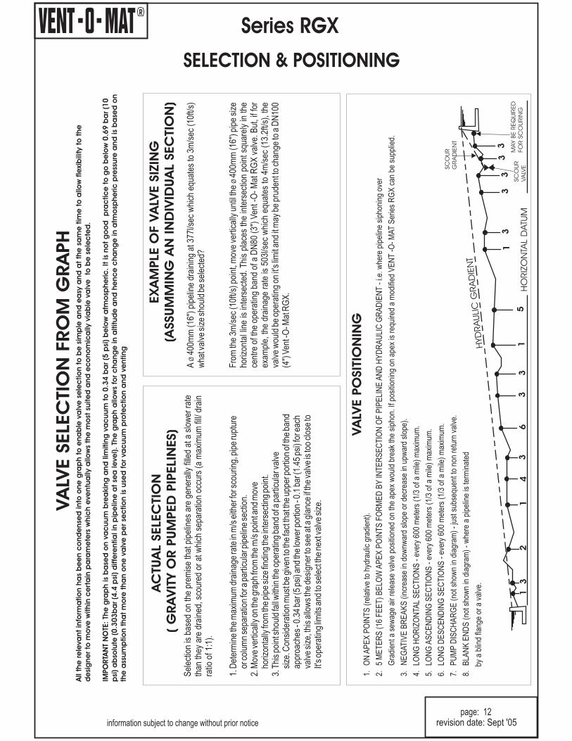
Sel
ectio
nis
base
don
the
prem
ise
that
pipe
lines
are
gene
rally
fille
dat
asl
ower
rate
than
they
are
drai
ned,
scou
red
orat
whi
chse
para
tion
occu
rs(a
max
imum
fill/
drai
nra
tioof
1:1)
.
1.D
eter
min
eth
em
axim
umdr
aina
gera
tein
m/s
eith
erfo
r sco
urin
g,pi
peru
ptur
eor
colu
mn
sepa
ratio
nfo
rapa
rtic
ular
pipe
line
sect
ion.
2.M
ove
vert
ical
lyon
the
grap
hfr
omth
em
/spo
int a
ndm
ove
horiz
onta
llyfr
omth
epi
pesi
zefin
ding
the
inte
rsec
ting
poin
t.3.
Thi
spo
int s
houl
dfa
llw
ithin
the
oper
atin
gba
ndof
apa
rtic
ular
valv
esi
ze.C
onsi
dera
tion
mus
tbe
give
nto
the
fact
that
the
uppe
rpor
tion
ofth
eba
ndap
proa
ches
-0.3
4ba
r (5
psi)
and
the
low
erpo
rtio
n-0
.1ba
r (1.
45ps
i)fo
reac
hva
lve
size
, thi
sal
low
sth
ede
sign
erto
see
ata
glan
ceif
the
valv
eis
too
clos
eto
It's
oper
atin
glim
itsan
dto
sele
ctth
ene
xtva
lve
size
.
AC
TUA
LSELEC
TIO
N
(G
RA
VIT
YO
RPUM
PED
PIP
ELIN
ES)
EX
AM
PLE
OF
VA
LVE
SIZ
ING
(ASSUM
MIN
GA
NIN
DIV
IDUA
LSEC
TIO
N)
VA
LVE
PO
SIT
ION
ING
1.O
NA
PE
XP
OIN
TS
(rel
ativ
eto
hydr
aulic
grad
ient
).
2.5
ME
TE
RS
(16
FE
ET
)B
ELO
WA
PE
XP
OIN
TS
FO
RM
ED
BY
INT
ER
SE
CT
ION
OF
PIP
ELI
NE
AN
DH
YD
RA
ULI
CG
RA
DIE
NT
-i.e
. whe
repi
pelin
esi
phon
ing
over
Gra
dien
t ase
wag
eai
rre
leas
eva
lve
posi
tione
don
the
apex
wou
ldbr
eak
the
siph
on. I
f pos
ition
ing
onap
exis
requ
ired
am
odifi
edV
EN
T-O
-M
AT
Ser
ies
RG
Xca
nbe
supp
lied.
3.N
EG
AT
IVE
BR
EA
KS
(incr
ease
indo
wnw
ard
slop
eor
decr
ease
inup
war
dsl
ope)
.
4.LO
NG
HO
RIZ
ON
TAL
SE
CT
ION
S-
ever
y60
0m
eter
s(1
/3of
am
ile)
max
imum
.
5.LO
NG
AS
CE
ND
ING
SE
CT
ION
S-
ever
y60
0m
eter
s(1
/3of
am
ile)
max
imum
.
6.LO
NG
DE
SC
EN
DIN
GS
EC
TIO
NS
-ev
ery
600
met
ers
(1/3
ofa
mile
)m
axim
um.
7.P
UM
PD
ISC
HA
RG
E(n
otsh
own
indi
agra
m)
-ju
stsu
bseq
uent
tono
nre
turn
valv
e.
8.B
LAN
KE
ND
S(n
otsh
own
indi
agra
m)
-w
here
api
pelin
eis
term
inat
ed
bya
blin
dfla
nge
ora
valv
e.
information subject to change without prior noticepage: 12
13
21
43
31
33
33
31
53
6
SC
OU
R
GRA
DIE
NT
MAY
BE
REQ
UIR
ED
FO
RSC
OU
RIN
GSC
OU
R
VA
LVE
HO
RIZ
ON
TAL
DATU
M
HYD
RA
ULIC
GRA
DIE
NT
revision date: Sept '05
A40
0mm
(16"
)pi
pelin
edr
aini
ngat
377l
/sec
whi
cheq
uate
sto
3m/s
ec(1
0ft/s
)w
hat v
alve
size
shou
ldbe
sele
cted
?
Fro
mth
e3m
/sec
(10f
t/s) p
oint
, mov
eve
rtic
ally
until
the
400m
m(1
6") p
ipe
size
horiz
onta
l lin
eis
inte
rsec
ted.
Thi
spl
aces
the
inte
rsec
tion
poin
tsq
uare
lyin
the
cent
reof
the
oper
atin
gba
ndof
aD
N80
(3")
Ven
t -O
-M
atR
GX
valv
e.B
ut, i
f for
exam
ple,
the
drai
nage
rate
is50
3l/s
ecw
hich
equa
tes
to4m
/sec
(13.
2ft/s
),th
eva
lve
wou
ldbe
oper
atin
gon
it's
limit
and
itm
aybe
prud
ent t
och
ange
toa
DN
100
(4")
Ven
t -O
-Mat
RG
X.
Ø
Ø
R
Series RGX
SURGE & WATERHAMMER PROTECTION
Introduction
Surge Protection - Initial Filling
Surge Protection - Pump Trip Conditions
Surge Protection - Pipeline Operating
The Vent-O-Mat Series RGX "Anti-Surge" sewage air release and vacuum break valve, is the product of extensive researchinto the development of an efficient, but cost effective solution to surge problems (both mass liquid oscillation and elastictransient phenomena) associated with any operating pipeline. Automatic dampening, relevant to the pipeline's needs isprovided by either one of three design features. These special features are unique in a pipeline component of suchcompact and economic design.
The RGX incorporates the additional floating "Anti-Surge" Orifice which is aerodynamically engineered to throttle airdischarge when liquid approach velocity would otherwise become too great and induce an unacceptable pressure rise. Theair throttling action increases resistance to the flow of the approaching liquid which consequently decelerates to a velocitywhich reduces the pressure rise when the valve closes (see operation of valve on pages 1 & 2). Vent-O-Mat series RGX isan essential precaution for pipeline priming.
In instances where a pipeline experiences liquid column separation due to pump stoppage, high shock pressures can begenerated when the separated liquid column rejoins.
The Vent-O-Mat series RGX takes in air through the unobstructed large orifice when liquid column separation occurs, butcontrols the discharge of air/gas through the "Anti-Surge" Orifice as the separated column commences to rejoin. Therejoining impact velocity is thereby considerably reduced to alleviate high surge pressures in the system (see operation ofvalve on pages 1 & 2).
Other surge control measures may, dependant on pipeline profile, diameter and operating conditions, be needed to providethe primary surge alleviation function with the Vent-O-Mat sewage air-valves forming an integral and valuable addition in acombined strategy for further reducing surge pressures. The benefit of the "Anti-Surge" Orifice can be readilydemonstrated by suitable surge modelling software.
The operation of valves and similar flow control devices can cause high-pressure transients in an operating pipeline.
The unique, single chamber design of the Vent-O-Mat series RGX valve enables a pocket of air to be trapped in the valvechamber.Automatic operation of the small orifice control float regulates the volume of air entrapped.
The volume maintained in the valve will provide a cushioning benefit to the pipeline for short duration transient pressure"spikes". This effect can be modelled by the design engineer using suitable surge software.
information subject to change without prior notice
page: 13revision date: Sept '05

R
Series RGX
SURGE & WATERHAMMER PROTECTION
Computer Modelling
Holistic Surge & Water Hammer Protection
Technical and Financial Benefits
S e r v i c e
The effectiveness of Vent-O-Mat series RGX has been substantiated by independent third party testing and bythousands of applications globally. Effective computer modelling, based on practical tests, has been ensured in the well-known and respected commercially available surge analysis software programmes such as FLOWMASTER,TRANSAM and
Vent-O-Mat forms an integral part of a well planned, holistic surge protection strategy that should, according toapplication needs and financial constraints, include surge vessels, check valves, control valves and/or any otherequipment needed to alleviate unacceptable surge behaviour.
The Vent-O-Mat series RGX valve offers definite financial and technical advantages when incorporated as part of aholistic surge protection strategy. This includes:
1. Improved alleviation of surge behaviour including reduction of:- Surge pressure magnitudes by slowing surge velocities- Duration of oscillation following a pump trip, as the sewage air-valve continuously absorbs and
dissipates the energies of the surge.
2. Potential for reduction in size and/or quantity of conventional surge protection devices such as surge vessels etc.
3. Automatic protection during initial filling when most surge protection devices are not operational.
4. Holistic protection as each sewage air valve installed has design features to automatically damp surges.
5. The valve is virtually maintenance free.
Vent-O-Mat is committed to finding the most cost effective and efficient solution to pipeline complexities. Servicesinclude air valve sizing and positioning and assistance to consulting engineers on defining appropriate surge and waterhammer protection strategies. Vent-O-Mat has built a sound relationship with many international consulting firms andhas gained global recognition for selling solutions!
SURGE 2000.
information subject to change without prior noticepage: 14
revision date: Sept '05
R
Series RGX
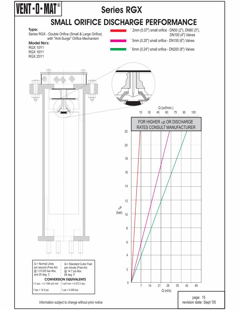
SMALL ORIFICE DISCHARGE PERFORMANCEType:
Model No's:
Series RGX - Double Orifice (Small & Large Orifice)with "Anti-Surge" Orifice Mechanism
RGX 10Y1RGX 16Y1RGX 25Y1
¨ 2mm (0.07") small orifice - DN50 (2"), DN80 (3"),DN100 (4") Valves
¨ 5mm (0.20") small orifice - DN150 (6") Valves
¨ 6mm (0.24") small orifice - DN200 (8") Valves
information subject to change without prior notice
page: 15
Q (scf/min.)
FOR HIGHER p OR DISCHARGERATES CONSULT MANUFACTURER
�
15 30 45 60 75 90 105
P(bar)�
20
25
18
16
14
12
10
8
6
4
2
0
revision date: Sept '05
Q (nl/s)
7 14 21 28 35 42 49
Q = Normal Litresper second (Free Air)@ 1.01325 bar Abs.and 20 deg. C
Q = Standard Cubic Feetper minute (Free Air)@ 14.7 psi Abs.68 deg. F
1
CONVERSION EQUIVALENTS1 l/ sec. = 2.1189 scf/ min. 1 scf/ min = 0.472 l/ sec.
1 bar = 14.5 psi 1 psi = 0.069 bar
R
Series RGX
Why?
information subject to change without prior noticepage: 16
"ANTI - SHOCK" - "ANTI - SURGE"
PERFORMANCE
QUALITY
SERVICEABILITY
VACUUM BREAK
COMPACTNESS
BACK UP
- The RGX is the only air release valve available that is suppliedas standard with a mechanism which operates automatically to prevent pipeline damage from the highinduced pressure transients associated with high velocity air discharge. Surge resulting from liquidcolumn separation and liquid oscillation is dramatically reduced as an automatic function of thismechanism.
- The RGX has been designed and developed to provide the optimum usable andsafe performance relative to all functions. Selection data has been substantiated through CSIR* andother testing and can therefore, be confidently referenced.
- The RGX economically offers the highest quality construction and materials available in anair release and vacuum break valve. Stringent manufacturing and test procedures are maintained toensure the best possible service and reliability is given by every valve produced.
- The RGX design facilitates extreme ease of service and maintenance.Components are in corrosion free materials to allow problem free disassembly and reassembly evenafter many years of operation.All maintenance spares are replaceable without special tools or skills.
- The RGX series large orifice diameters equal the nominal size of the valve, i.e., a200mm (8") valve has a 200mm (8") orifice. This ensures the least possible resistance to the intake of airand consequently the least possible negative pressure within a draining pipeline.
- Although extremely robust the RGX valve's lightweight and compact constructionoffers handling transport and installation advantages.
- Vent -O- Mat provides highly committed customer orientated sales, service, spares andtechnical back up - TRY US!!!
* Council for Scientific and Industrial Research
revision date: Sept '05
R
Series RGX
PURCHASE SPECIFICATION
information subject to change without prior noticepage: 17
revision date: Sept '05
VENT -O- MAT MODEL NO.
CONSTRUCTION & DESIGN
Nuts and washers shall be excluded.
OPERATION
Page 9 - Series RGX - DN50 (2") to DN200 (8").
The Sewage Air Release & Vacuum Break Valve shall consist of a compact tubular all stainless steel fabricatedbody, hollow direct acting float and solid large orifice float in H.D.P.E. - stainless steel nozzle and woven dirtinhibitor screen, EPDM rubber seals and seat.
The valve shall have an integral "Anti-Surge" Orifice mechanism which shall operate automatically to limittransient pressure rise or shock induced by closure to less than 1.5 x valve rated working pressure.
The intake orifice area shall be equal to the nominal size of the valve i.e., a 150mm (6") valve shall have a150mm (6") intake orifice. Large orifice sealing shall be effected by the flat face of the control float seatingagainst a EPDM rubber 'O' ring housed in a dovetail groove circumferentially surrounding the orifice.
Discharge of pressurized air shall be controlled by the seating & unseating of a small orifice nozzle on a naturalrubber seal affixed into the control float. The nozzle shall have a flat seating land surrounding the orifice so thatdamage to the rubber seal is prevented.The valve construction shall be proportioned with regard to material strength characteristics, so thatdeformation, leaking or damage of any kind does not occur by submission to twice the designed workingpressure.
Connection to the valve inlet shall be facilitated by flanged ends conforming to PN10, 16 or 25 ratings ofBS4504 or SABS 1123 Standards or ANSI B16.1 Class 125 & Class 250 and ANSI B16.5 Class 150 and Class300 Standards. DN50 valves are supplied with 2” male nipples as standard. As4087 Fig. B7 - B9, AS 2129Table E/F. Flanged ends shall be supplied with the requisite number of stainless steel screwed studs insertedfor alignment to the specified standard.
1. Prior to the ingress of liquid into the valve chamber, as when the pipeline is being filled, valves shallvent through the large orifice when sewage/effluent approach velocities are relative to a transientpressure rise, on valve closure, of < 1.5 x valve rated pressure.At higher sewage/effluent approach velocities, which have a potential to induce transient pressure rises> 1.5 x valve rated pressure on valve closure, the valve shall automatically discharge air/gas throughthe "Anti-Surge" Orifice and reduce sewage/effluent approach velocity, so that on closure a maximumTransient pressure rise of < 1.5 x valve rated pressure is realised.
2. Valves shall not exhibit leaks or weeping of liquid past the large orifice seal at operating pressures of0,5 bar (7.2 psi) to 1.5 x valve rated working pressure.
3. Valves shall respond to the presence of air/gas by discharging it through the small orifice at anypressures within a specified design range, i.e. 0,5 bar (7.2 psi) to 10 bar (145 psi) and shall remainleak tight in the absence of air.
4. Valves shall react immediately to pipeline drainage or liquid column separation by the full opening of thelarge orifice so as to allow unobstructed air intake at the lowest possible negative internal pipelinepressure.
Page 10 - Series RGX - DN50 (2") to DN200 (8"). (Expanded Body)
R
Series RGX
ORDERING GUIDE
VALVE SERIES No.
ANTI-SURGE ORIFICE:
VALVE TYPE:
DOUBLE ACTING 1
0 5 0 R G X 1 0 1 1
information subject to change without prior noticepage: 18
revision date: Sept '05
VALVE END CONNECTION:
STUDDED FLANGED - Bs4504 or SABS 1123 0STUDDED FLANGED - ANSI B16.1 & B16.5 3STUDDED FLANGED - AS 4087 Fig. B7 - B9 4AS 2129 Table F 5AS 2129 Table E 6
THREADED - BSP MALE 1THREADED - NPT MALE 2
VALVE PRESSURE RATING:
PN10 (145 psi) 1 0
PN16 (232 psi) 1 6
PN25 (363 psi) 2 5
VALVE SIZE:
DN50 (2") - 0 5 0
DN80 (3") - 0 8 0
Dn100 (4") - 1 0 0
DN150 (6") - 1 5 0DN200 (8") - 2 0 0
Note:
All air release valves supplied shall be subjected to the following testing procedures in the order
laid down:
IMPORTANT NOTE:
1. DN250 (10”) and DN300 (12”) valves are available on request.
(A) A high pressure strength and leak test whereby the valve is filled with water and pressurized to twice the ratedworking pressure which shall be held for a period of 2 minutes. Any leaking, weeping or sweating shall bereason for rejection.
(B) A low head leak test whereby the valve is filled with water and pressurized to a maximum of 0,5 bar (7.2 psi)using a visible water column connected to the test rig. The valve shall be rejected if leak tightness is notmaintained for 2 minutes.
(C) Every tenth air release valve of the same size and pressure rating must be subjected to a small orifice function test"DROP TEST" - whereby the valve is filled with water, pressurized to above rated working pressure and isolatedfrom the test rig by closure of an isolating valve. A chamber in the test rig immediately prior to the isolating valvemust be filled with compressed air at a pressure equal to that being maintained in the air release valve. Theisolating valve is then opened so as to allow the air to rise in the air release valve without the pressure droppinglower than 2 - 3 bar (29 - 44 psi) above rated working pressure of the air release valve. The "DROP TEST" is thencarried out by slowly bleeding off the pressure through a suitable cock until rated working pressure is reached andthe float drops away from the orifice to allow discharge. Failure of the air release valve to function in the mannerdescribed will be reason for rejection.
On request the manufacturer shall provide batch certificates of test compliance which shall be cross referenced to serialnumbers indelibly marked onto the identity label of each valve.
It is impossible to inject air into an incompressible liquid, air injection can only be achieved if theliquid can be displaced which implies that the pressure in the test rig must be reduced to atmospheric, and absolutelynothing is proven by discharge through the small orifice of the air release valve at atmospheric pressure. "DROP TESTING"in this manner is not acceptable.
TEST SPECIFICATION

R
Series RGXb
OPERATION
VENTING
(PUMP START UP)
2
"Anti - Surge" Orifice
"Anti - Surge" Float
information subject to change without prior notice
page: 19
PRESSURIZED AIR/GAS RELEASE
PUMP OPERATING
4
Normal Operating Level(Small Orifice ControlFloat Buoyancy Level)
10 bar (145 psi)Working Pressure
Maximum Surge Level
VACUUM RELIEF (AIR INTAKE)
PIPELINE DRAINING
1
PIPELINE FULLY CHARGED
3
revision date: Sept '05

PRE NOTES:
VACUUM RELIEF (AIR INTAKE)
VENTING (PUMP START UP)
PRESSURIZED AIR RELEASE FROM A FULL PIPELINE
PRESSURIZED AIR RELEASE (PUMP OPERATING)
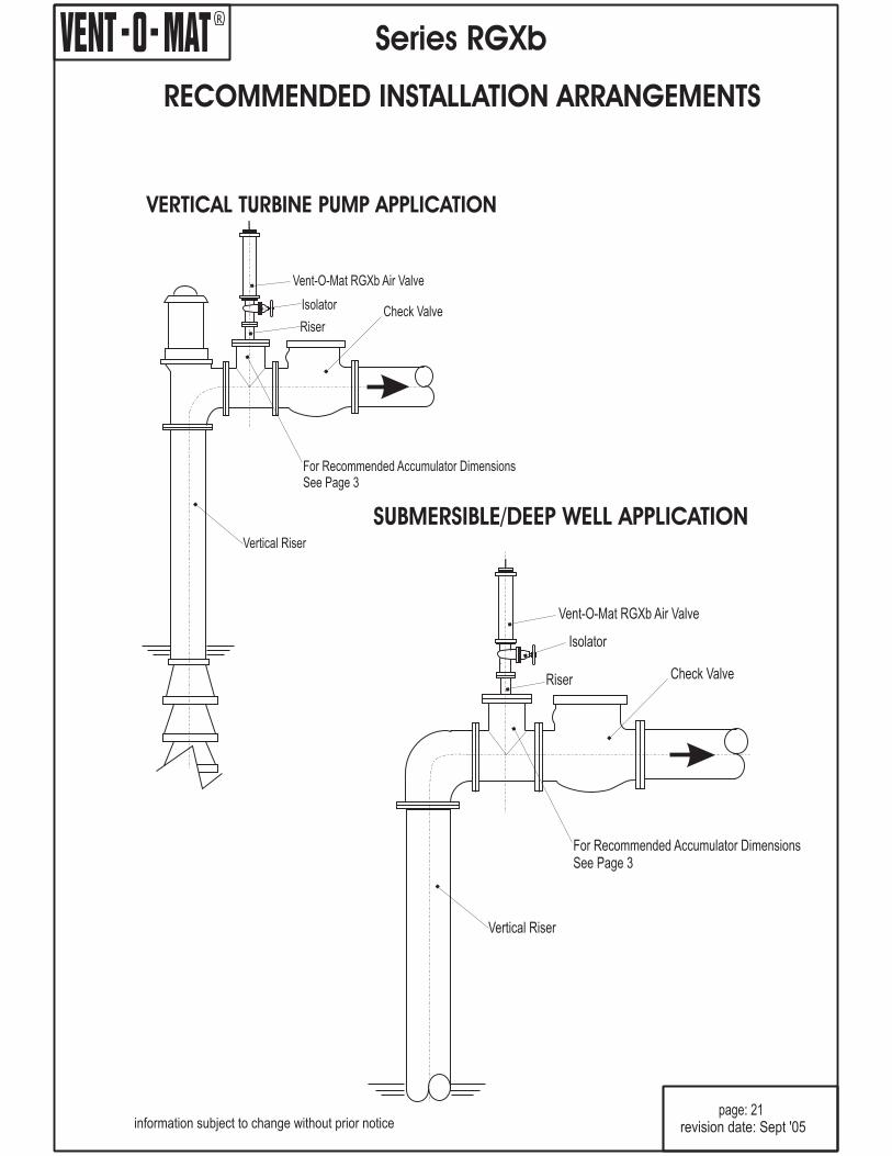
It is good engineering practice to install a sewage air valve prior to the pump discharge check valve, on vertical turbinepumps and deepwell submersible pump applications. The purpose of these valves is to control air/gas entry into the mainpipeline on initial pump start up and to fully break vacuum in the vertical riser upon pump shutoff.
Operation of conventional sewage air valves in this application is such that the air in the vertical riser is released very rapidlyupon pump startup, resulting in very high pressure transients when the liquid column slams the sewage air valve shut and/orslams into the closed discharge check valve.
The Vent-O-Mat Series RGXb valve has specifically been developed for use on deep well submersible pump and verticalturbine pump applications where they are installed prior to the pump discharge check valve to fulfill the following functions:
Provide effective release of air/gas in the vertical riser upon pump startup.
Dampen surge pressures upon startup.
Provide vacuum protection when the pump stops and the vertical column drains.
Upon pump stop, the discharge check valve closes. Sewage/effluent drains from the sewage air valve and the pump'svertical column. The negative differential created by the draining liquid causes atmospheric air to push the "Anti-Surge" Floatdown, opening the Large Orifice and allows air to displace the draining liquid to prevent potentialy damaging internalnegative pressure*.The hollow smooth side float design, discourages the adherence of solids and viscous substances which, therefore tend towithdraw from the valve into the pipeline when draining occurs, for this reason
Air/gas is forced through the "Anti-Surge" Orifice resulting in the deceleration of the approaching liquid column due to theresistance of rising air pressure in the valve.This dampens transients when the sewage air valve closes and the liquid column opens the discharge check valve.
Sewage/effluent has entered the valve chamber and buoyed the floats to close both the "Anti-Surge" orifice and the smallorifice. The design's compression/volume relationship prevents the media from ever exceeding the maximum surge levelindicated in diagram 3. The resultant sewage/effluent free area protects against the fouling of the orifice seals by solids orhigh viscous substances - for this reason.
The volume of disentrained air/gas increases in the valve and displaces the sewage/effluent level to the lower, normaloperating level (small orifice control float buoyancy level ) Any additional lowering of the sewage/effluent level, as wouldoccur when more air/gas enters the valve, will result in the control float dropping away from the small orifice through whichpressurized air/gas is then being discharged to atmosphere.The control float will close the small orifice when sufficient air/gas has been released to restore the sewage/effluent level tothe normal operating level.The considerable sewage/effluent free are obviates the possibility of leaks that could otherwise be caused by solids enteringthe sealing areas - for this reason.
A differential pressure of less than 0.05 bar (0.7 psi) across the large orifice is required to open the valve fully under vacuumconditions.
NO FLUSHING CONNECTIONS ARE
NECESSARY
NO FLUSHING CONNECTIONS ARE NECESSARY.
NO FLUSHING CONNECTIONS ARE NECESSARY
*Note:
�
�
�
R
page: 20
Series RGXb
OPERATION
1.
2.
3.
4.
revision date: Sept '05information subject to change without prior notice
R
RECOMMENDED INSTALLATION ARRANGEMENTS
Series RGXb
page: 21
SUBMERSIBLE/DEEP WELL APPLICATION
Vertical Riser
Check Valve
For Recommended Accumulator DimensionsSee Page 3
Riser
Isolator
Vent-O-Mat RGXb Air Valve
VERTICAL TURBINE PUMP APPLICATION
Vertical Riser
Check ValveRiser
Isolator
For Recommended Accumulator DimensionsSee Page 3
Vent-O-Mat RGXb Air Valve
revision date: Sept '05information subject to change without prior notice
R
Series RGXb
information subject to change without prior notice
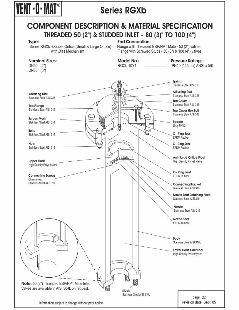
page: 22
Top CoverStainless Steel AISI 316
Adjusting RodStainless Steel AISI 316
SpringStainless Steel AISI 316
SpacerGrey P.V.C.
Top Cover Hex BoltStainless Steel AISI 316
Top FlangeStainless Steel AISI 316
Locating DiskStainless Steel AISI 316
Screen MeshStainless Steel AISI 316
BoltsStainless Steel AISI 316 O - Ring Seal
EPDM Rubber
NutsStainless Steel AISI 316
StudsStainless Steel AISI 316L
Upper FloatHigh Density Polyethylene
Connecting ScrewsCheeseheadStainless Steel AISI 316
NozzleStainless Steel AISI 316
Nozzle SeatEPDM Rubber
Connecting BracketStainless Steel AISI 316
O - Ring SeatEPDM Rubber
Nozzle Seat Retaining PlateStainless Steel AISI 316
Lower Float AssemblyHigh Density Polyethylene
BodyStainless Steel AISI 316L
Anti-Surge Orifice FloatHigh Density Polyethylene
COMPONENT DESCRIPTION & MATERIAL SPECIFICATIONSTUDDED INLET - 80 (3)" TO 100 (4")THREADED 50 (2") &
revision date: Sept '05
Note: 50 (2Valves are available in AISI 304L on request.
") Threaded BSP/NPT Male Inlet
O - Ring SealEPDM Rubber
Type: End Connection:
Nominal Sizes: Model No's: Pressure Ratings:
Series RGXb -Double Orifice (Small & Large Orifice)with Mechanism
DN50 (2") RGXb 10Y1 PN10 (145 psi) ANSI #150DN80 (3")
Bias
Flange with Threaded BSP/NPT Male - 50 (2") valves.Flange with Screwed Studs - 80 (3") & 100 (4") valves.

R
StudsStainless Steel AISI 316L
BodyStainless Steel AISI 316L
Series RGXb
Page: 23
Top CoverStainless Steel AISI 316
Adjusting RodStainless Steel AISI 316
SpringStainless Steel AISI 316
SpacerGrey P.V.C.
Top Cover Hex BoltStainless Steel AISI 316
O - Ring SealEPDM Rubber
Anti-Surge Orifice FloatHigh Density Polyethylene
Top FlangeStainless Steel AISI 316
Locating DiskStainless Steel AISI 316
Screen MeshStainless Steel AISI 316
BoltsStainless Steel AISI 316
NutsStainless Steel AISI 316
Connecting ScrewsCheeseheadStainless Steel AISI 316
information subject to change without prior notice
NozzleStainless Steel AISI 316
Nozzle SeatEPDM Rubber
Connecting BracketStainless Steel AISI 316
Nozzle Seat Retaining PlateStainless Steel AISI 316
Lower Float AssemblyHigh Density Polyethylene
Type: End Connection:
Nominal Sizes: Model No's: Pressure Ratings:
Series RGXb - Double Orifice (Small & Large Orifice)with Mechanism
DN50 (2") RGXb 16Y1 PN16 (232 psi)ANSI #125DN80 (3”) RGXb 25Y1 PN25 (363 psi) ANSI #250
Bias
“Flange with Threaded BSP/NPT Male - 50 (2") valves.Flange with Screwed Studs - 80 (3") & 100 (4") valves
DN100 (4”)
COMPONENT DESCRIPTION & MATERIAL SPECIFICATIONSTUDDED INLET - 80 (3") TO 100 (4") EXPANDED BODYTHREADED 50 (2") &
O - Ring SealEPDM Rubber
Upper FloatHigh Density Polyethylene
revision date: Sept '05
Note: 50 (2Valves are available in AISI 304L on request.
") Threaded BSP/NPT Male Inlet
O - Ring SealEPDM Rubber
R
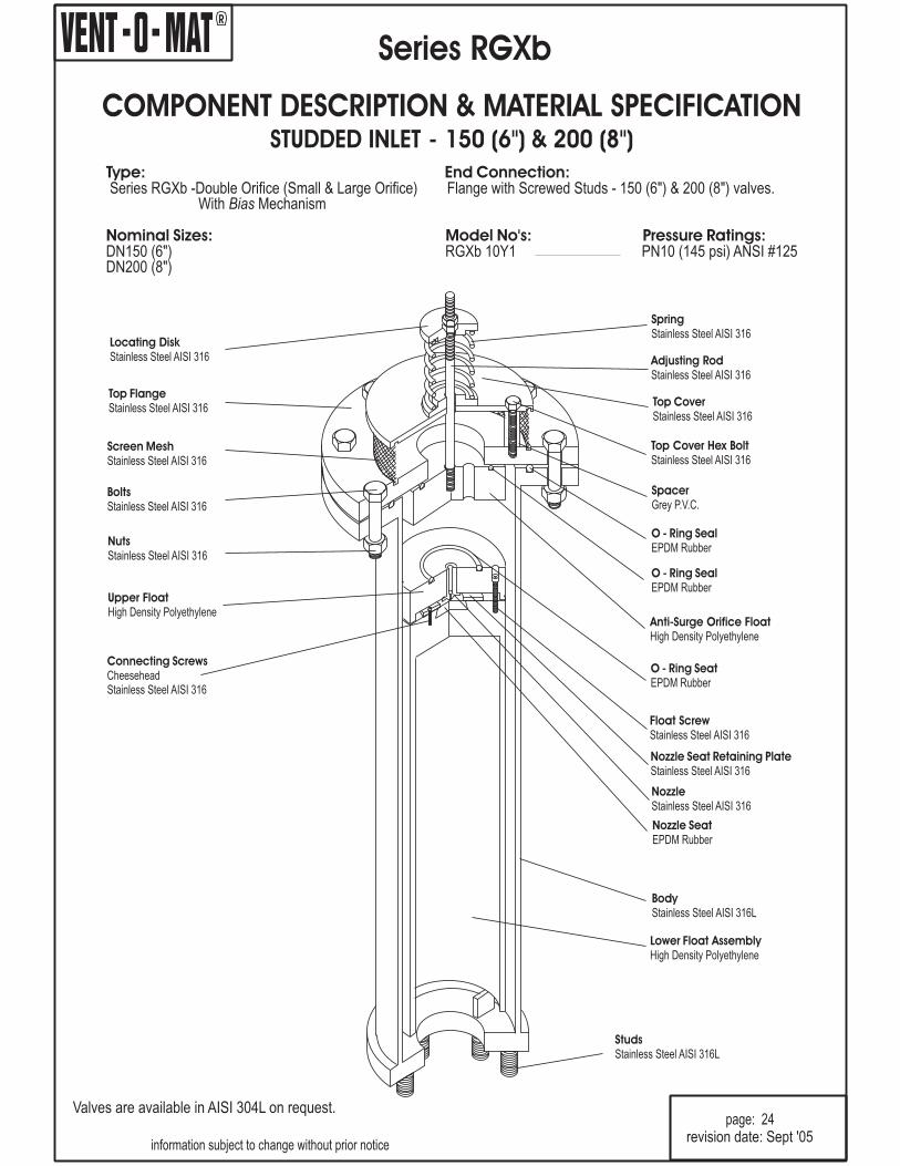
Type: End Connection:
Nominal Sizes: Model No's: Pressure Ratings:
Series RGXb -Double Orifice (Small & Large Orifice) Flange with Screwed Studs - 150 (6 & 200 (8 valves.With Mechanism
DN150 (6") RGXb 10Y1 PN10 (145 psi) ANSI #125DN200 (8")
Bias
") ")
COMPONENT DESCRIPTION & MATERIAL SPECIFICATIONSTUDDED INLET - 150 (6") & 200 (8")
Series RGXb
information subject to change without prior notice
page: 24
Top CoverStainless Steel AISI 316
Adjusting RodStainless Steel AISI 316
SpringStainless Steel AISI 316
SpacerGrey P.V.C.
Top Cover Hex BoltStainless Steel AISI 316
Top FlangeStainless Steel AISI 316
Locating DiskStainless Steel AISI 316
Screen MeshStainless Steel AISI 316
BoltsStainless Steel AISI 316
O - Ring SealEPDM Rubber
Anti-Surge Orifice FloatHigh Density Polyethylene
NutsStainless Steel AISI 316
StudsStainless Steel AISI 316L
Upper FloatHigh Density Polyethylene
Connecting ScrewsCheeseheadStainless Steel AISI 316
NozzleStainless Steel AISI 316
Nozzle SeatEPDM Rubber
Float ScrewStainless Steel AISI 316
O - Ring SeatEPDM Rubber
Nozzle Seat Retaining PlateStainless Steel AISI 316
Lower Float AssemblyHigh Density Polyethylene
BodyStainless Steel AISI 316L
revision date: Sept '05
O - Ring SealEPDM Rubber
Valves are available in AISI 304L on request.
R
StudsStainless Steel AISI 316L
Series RGXb
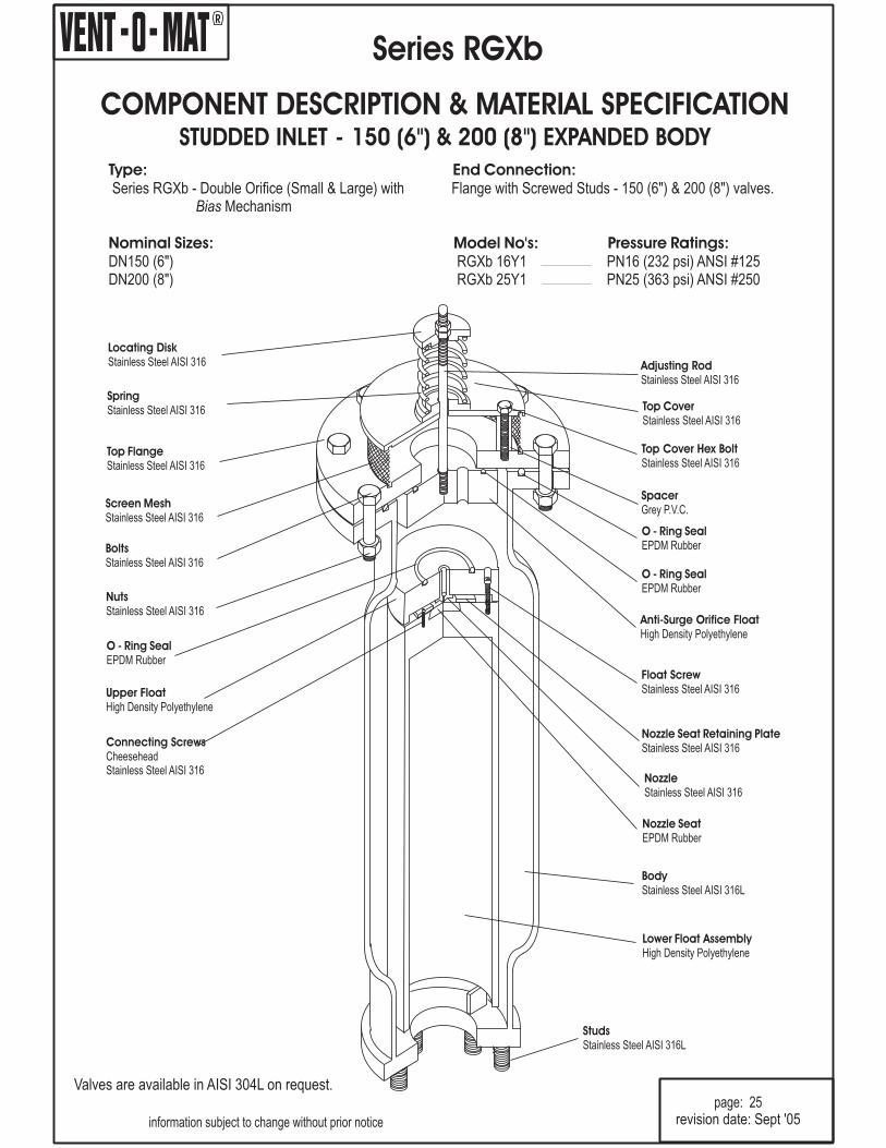
Type: End Connection:
Nominal Sizes: Model No's: Pressure Ratings:
Series RGXb - Double Orifice (Small & Large) withMechanism
DN150 (6") RGXb 16Y1 PN16 (232 psi) ANSI #125DN200 (8") RGXb 25Y1 PN25 (363 psi) ANSI #250
Bias
Flange with Screwed Studs - 150 (6") & 200 (8") valves.
information subject to change without prior notice
page: 25
Top CoverStainless Steel AISI 316
Adjusting RodStainless Steel AISI 316
SpringStainless Steel AISI 316
SpacerGrey P.V.C.
Top Cover Hex BoltStainless Steel AISI 316
O - Ring SealEPDM Rubber
Anti-Surge Orifice FloatHigh Density Polyethylene
Top FlangeStainless Steel AISI 316
Locating DiskStainless Steel AISI 316
Screen MeshStainless Steel AISI 316
BoltsStainless Steel AISI 316
NutsStainless Steel AISI 316
Connecting ScrewsCheeseheadStainless Steel AISI 316
BodyStainless Steel AISI 316L
NozzleStainless Steel AISI 316
Nozzle SeatEPDM Rubber
Float ScrewStainless Steel AISI 316
Nozzle Seat Retaining PlateStainless Steel AISI 316
Lower Float AssemblyHigh Density Polyethylene
Upper FloatHigh Density Polyethylene
COMPONENT DESCRIPTION & MATERIAL SPECIFICATIONSTUDDED INLET - 150 (6") & 200 (8") EXPANDED BODY
O - Ring SealEPDM Rubber
revision date: Sept '05
O - Ring SealEPDM Rubber
Valves are available in AISI 304L on request.

R
Type:
End Connection:
Nominal Sizes:
Model No's: Pressure Ratings - bar (psi):
Operating Pressure Range - psi:
Function:
Valve Selection:-
Materials of Construction:-
Installation:-
Standard Factory Tests:
Double Orifice (Small & Large Orifice) with mechanismfor large volume air intake and controlled air discharge.
DN50 (2"), DN80 (3"), DN100 (4"), DN150 (6") & DN200 (8")
RGXb 10Y1 PN10 (145 psi) ANSI #125
Min Max.PN10 (145 psi)ANSI #125 0.5 (7.2) 10 (145)
i) High volume air intake - pipeline drainingii) Pressurized air/gas discharge - pipeline filled.iii) Controlled air discharge - pipeline filling.iv) Surge dampening - high velocity air/gas discharge,
liquid column separation & liquid oscillation.
see pages 11 & 12
see pages 22 & 24
see page 21
i) Hydrostatic test -1.5 x max. rated working pressureii) Low head leak test - 0.5 bar (7.2 psi)iii) Small orifice function test at max. rated working pressure
(minimum 1 valve in 10).
Bias
Flange with DN50 (2") Male BSP/NPT Threaded and ScrewedStuds for Alignment to BS4504 PN16 & PN25, SABS1123Tables 1600/3 & 2500/3, ANSI B16.1 Class 125 & Class 250 orAs4087 Fig. B7 - B9 / AS 2129 Table D/E/F.
Series RGXb
page: 26
information subject to change without prior notice
R
DE A
A
OVERALL DIMENSIONS & WEIGHTS
GENERAL SPECIFICATIONSTHREADED 50 (2 & STUDDED INLET - 80 (3") TO 200 (8") ")
C
B
F
revision date: Sept '05
80 080 RGXb 10Y1 285 885 55 200 80 36.7N/A
100 100 RGXb 10Y1 285 885 55 220 100 36.2N/A
150 150 RGXb 10Y1 395 1230 55 285 150 82.4N/A
200 200 RGXb 10Y1 445 1230 55 340 200 103.4N/A
DN Model No. A B C D E F Weightmm mm mm mm mm mm kgmm
50 050 RGXb 10Y1 220 850 N/A 125 50 42 18.1
Y4 = AS 4087 Fig. B7 - B9, 5 = AS 2129 Table F, 6 = AS 2129 Table E
Note: DN50 (2") valves have Dn50 (2") BSP/NPT male inlet connections as standard.
R
Series RGXb
page: 27
information subject to change without prior notice
R
OVERALL DIMENSIONS & WEIGHTS
DE A
A
F
B
C
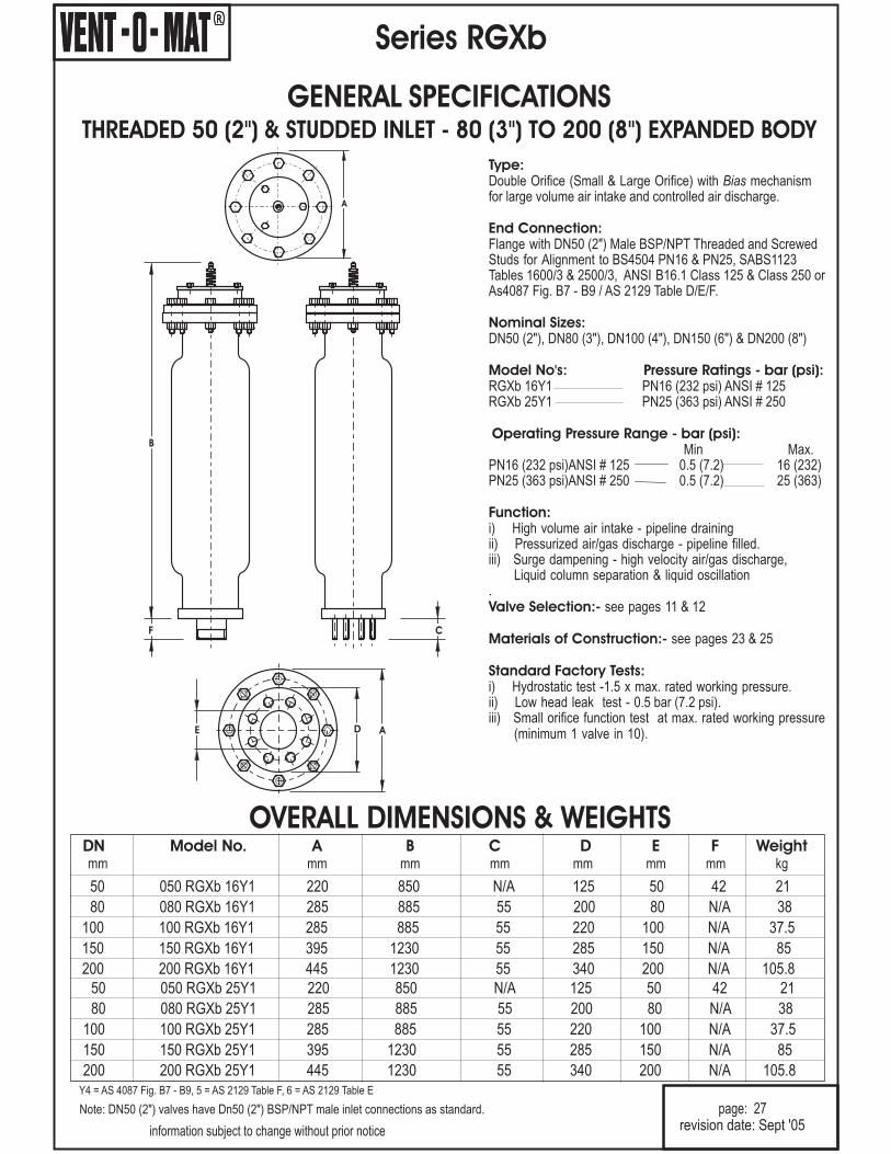
GENERAL SPECIFICATIONSTHREADED 50 (2 & STUDDED INLET - 80 (3") TO 200 (8") ") EXPANDED BODY
revision date: Sept '05
80 080 RGXb 16Y1 285 885 55 200 80 38N/A
100 100 RGXb 16Y1 285 885 55 220 100 37.5N/A
150 150 RGXb 16Y1 395 1230 55 285 150 85N/A
200 200 RGXb 16Y1 445 1230 55 340 200 105.8N/A
DN Model No. A B C D E F Weightmm mm mm mm mm mm kgmm
50 050 RGXb 16Y1 220 850 N/A 125 50 42 21
80 080 RGXb 25Y1 285 885 55 200 80 38N/A
100 100 RGXb 25Y1 285 885 55 220 100 37.5N/A
150 150 RGXb 25Y1 395 1230 55 285 150 85N/A
200 200 RGXb 25Y1 445 1230 55 340 200 105.8N/A
50 050 RGXb 25Y1 220 850 N/A 125 50 42 21
Y4 = AS 4087 Fig. B7 - B9, 5 = AS 2129 Table F, 6 = AS 2129 Table E
Note: DN50 (2") valves have Dn50 (2") BSP/NPT male inlet connections as standard.
Type:
End Connection:
Nominal Sizes:
Model No's: Pressure Ratings - bar (psi):
Operating Pressure Range - bar (psi):
Function:
Valve Selection:-
Materials of Construction:-
Standard Factory Tests:
Double Orifice (Small & Large Orifice) with mechanismfor large volume air intake and controlled air discharge.
DN50 (2"), DN80 (3"), DN100 (4"), DN150 (6") & DN200 (8
RGXb 16Y1 PN16 (232 psi) ANSI # 125RGXb 25Y1 PN25 (363 psi) ANSI # 250
Min Max.
i) High volume air intake - pipeline drainingii) Pressurized air/gas discharge - pipeline filled.iii) Surge dampening - high velocity air/gas discharge,
Liquid column separation & liquid oscillation.
see pages 11 & 12
see pages 23 & 25
i) Hydrostatic test -1.5 x max. rated working pressure.ii) Low head leak test - 0.5 bar (7.2 psi).iii) Small orifice function test at max. rated working pressure
(minimum 1 valve in 10).
Bias
0.5 (7.2) 16 (232)0.5 (7.2) 25 (363)
Flange with DN50 (2") Male BSP/NPT Threaded and ScrewedStuds for Alignment to BS4504 PN16 & PN25, SABS1123Tables 1600/3 & 2500/3, ANSI B16.1 Class 125 & Class 250 orAs4087 Fig. B7 - B9 / AS 2129 Table D/E/F.
")
PN16 (232 psi)ANSI # 125PN25 (363 psi)ANSI # 250

R
Series RGXb
PURCHASE SPECIFICATION
information subject to change without prior notice
page: 28revision date: Sept '05
VENT-O-MAT MODEL NO.
OPERATION
The Sewage Air Release & Vacuum Break Valve shall consist of a compact tubular all stainless steelfabricated body, hollow direct acting float and solid large orifice float in H.D.P.E. - stainless steel nozzleand woven dirt inhibitor screen, EPDM rubber seals and seat.
The valve shall have an integral 'Anti-Surge' Orifice mechanism which shall operate automatically to limitsurge pressures or shock induced by liquid oscillation and/or rapid air/gas discharge to less than 1.5 xv a l v e r a t e d w o r k i n g p r e s s u r e .
The intake orifice area shall be equal to the nominal size of the valve i.e., a DN150 (6") valve shall havea DN150 (6") intake orifice. Large orifice sealing shall be effected by the flat face of the control floatseating against a EPDM rubber 'O' ring housed in a dovetail groove circumferentially surrounding theo r i f i c e .
Discharge of pressurized air shall be controlled by the seating & unseating of a small orifice nozzle on aEPDM rubber seal affixed into the control float. The nozzle shall have a flat seating land surrounding theorifice so that damage to the rubber seal is prevented.The valve construction shall be proportioned with regard to material strength characteristics, so thatdeformation, leaking or damage of any kind does not occur by submission to twice the designed workingpressure
Flanged ends shall be supplied with the requisite number of stainless steel screwed studs inserted foralignment to the specified standard.
1. Prior to the ingress of liquid into the valve chamber, as when the pipeline is being filled, valves shall ventthrough the "Anti-Surge" orifice when sewage/effluent approach velocities are relative to a transientpressure rise, on valve closure, of < 1.5 x valve rated pressure.
2. Valves shall not exhibit leaks or weeping of liquid past the large orifice seal at operating pressures of 0.5bar (7.2 psi) to 1.5 x rated working pressure.
3. Valves shall respond to the presence of air/gas by discharging it through the small orifice at any pressureswithin a specified design range, i.e. 0.5 bar (7.2 psi) to 10 bar (145 psi) and shall remain leak tight in theabsence of air.
4. Valves shall react immediately to pipeline drainage or water column separation by the full opening of thelarge orifice so as to allow unobstructed air intake at the lowest possible negative internal pipelinepressure.
Nuts and washers shall be excluded.
Page 26 - Series RGXb - DN50 (2") to DN200 (8").Page 27 - Series RGXb - DN50 (2") to DN200 (8") (Expanded Body).
CONSTRUCTION & DESIGN
Connection to the valve inlet shall be facilitated by flanged ends conforming to PN10, 16 or 25 ratings ofBS4504 or SABS 1123 Standards or ANSI B16,1 Class 125 or Class 250 and B16.5 Class 150 and Class 300Standards. AS 4087 Fig. B7 - B9, AS 2129 Table E/F.
R
Series RGXv
OPERATION
VENTING OF A FILLING PIPELINE
(SUB CRITICAL SEWAGE/ EFFLUENT
APPROACH VELOCITY)
"Anti - Surge" Orifice
Upper Chamber Float
information subject to change without prior notice
page: 29
1
VENTING OF A FILLING PIPELINE
(EXCESSIVE SEWAGE/ EFFLUENT
APPROACH VELOCITY)
2
PIPELINE FULLY CHARGED
3
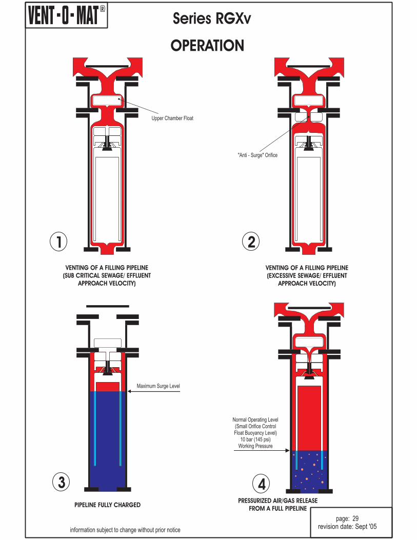
Maximum Surge Level
PRESSURIZED AIR/GAS RELEASE
FROM A FULL PIPELINE
4
Normal Operating Level(Small Orifice ControlFloat Buoyancy Level)
10 bar (145 psi)Working Pressure
revision date: Sept '05
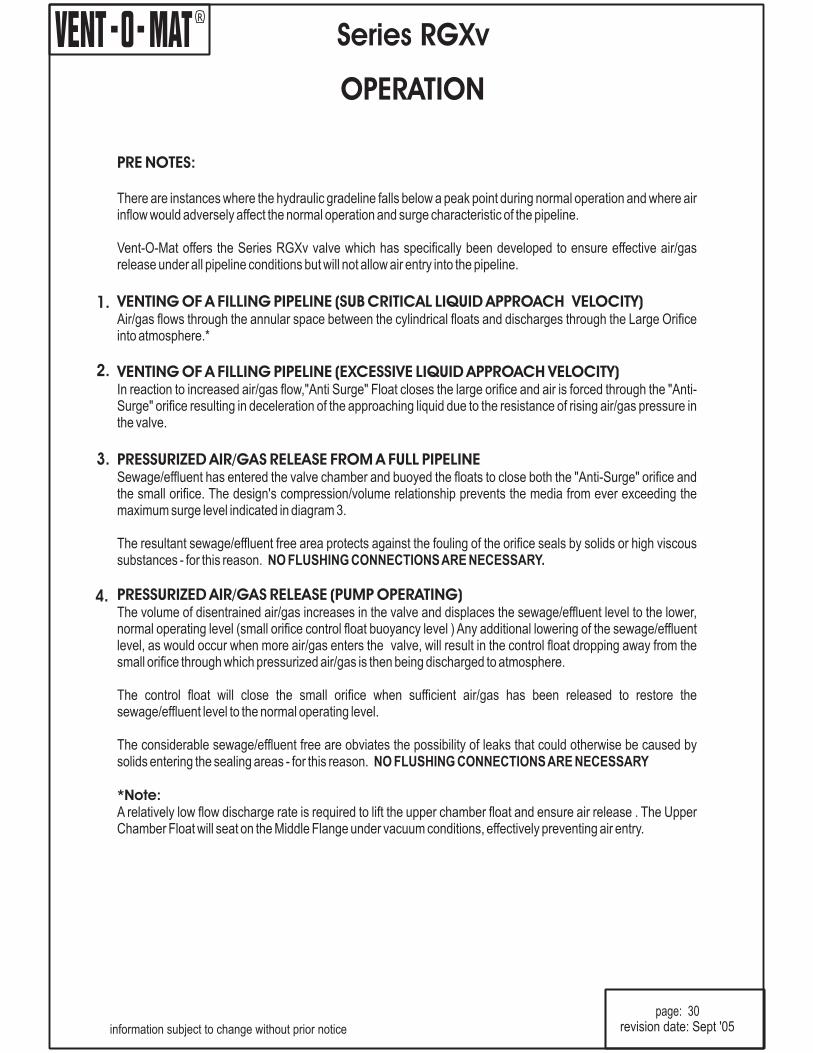
PRE NOTES:
VENTING OF A FILLING PIPELINE (SUB CRITICAL LIQUID APPROACH VELOCITY)
VENTING OF A FILLING PIPELINE (EXCESSIVE LIQUID APPROACH VELOCITY)
PRESSURIZED AIR/GAS RELEASE FROM A FULL PIPELINE
PRESSURIZED AIR/GAS RELEASE (PUMP OPERATING)
There are instances where the hydraulic gradeline falls below a peak point during normal operation and where airinflow would adversely affect the normal operation and surge characteristic of the pipeline.
Vent-O-Mat offers the Series RGXv valve which has specifically been developed to ensure effective air/gasrelease under all pipeline conditions but will not allow air entry into the pipeline.
Air/gas flows through the annular space between the cylindrical floats and discharges through the Large Orificeinto atmosphere.*
In reaction to increased air/gas flow,"Anti Surge" Float closes the large orifice and air is forced through the "Anti-Surge" orifice resulting in deceleration of the approaching liquid due to the resistance of rising air/gas pressure inthe valve.
Sewage/effluent has entered the valve chamber and buoyed the floats to close both the "Anti-Surge" orifice andthe small orifice. The design's compression/volume relationship prevents the media from ever exceeding themaximum surge level indicated in diagram 3.
The resultant sewage/effluent free area protects against the fouling of the orifice seals by solids or high viscoussubstances - for this reason.
The volume of disentrained air/gas increases in the valve and displaces the sewage/effluent level to the lower,normal operating level (small orifice control float buoyancy level ) Any additional lowering of the sewage/effluentlevel, as would occur when more air/gas enters the valve, will result in the control float dropping away from thesmall orifice through which pressurized air/gas is then being discharged to atmosphere.
The control float will close the small orifice when sufficient air/gas has been released to restore thesewage/effluent level to the normal operating level.
The considerable sewage/effluent free are obviates the possibility of leaks that could otherwise be caused bysolids entering the sealing areas - for this reason.
A relatively low flow discharge rate is required to lift the upper chamber float and ensure air release . The UpperChamber Float will seat on the Middle Flange under vacuum conditions, effectively preventing air entry.
NO FLUSHING CONNECTIONSARE NECESSARY.
NO FLUSHING CONNECTIONSARE NECESSARY
*Note:
R
page: 30
Series RGXv
OPERATION
1.
2.
4.
3.
revision date: Sept '05information subject to change without prior notice
R
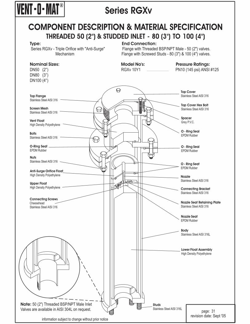
Top CoverStainless Steel AISI 316
SpacerGrey P.V.C.
Top Cover Hex BoltStainless Steel AISI 316
O - Ring SealEPDM Rubber
Top FlangeStainless Steel AISI 316
Screen MeshStainless Steel AISI 316
BoltsStainless Steel AISI 316
Vent FloatHigh Density Polyethylene
Upper FloatHigh Density Polyethylene
Nozzle Seat Retaining PlateStainless Steel AISI 316
Nozzle SeatEPDM Rubber
NutsStainless Steel AISI 316
O-Ring SeatEPDM Rubber
NozzleStainless Steel AISI 316
Anti-Surge Orifice FloatHigh Density Polyethylene
O - Ring SeatEPDM Rubber
Connecting BracketStainless Steel AISI 316
Lower Float AssemblyHigh Density Polyethylene
Connecting ScrewsCheeseheadStainless Steel AISI 316
BodyStainless Steel AISI 316L
Series RGXv
Type: End Connection:
Nominal Sizes: Model No's: Pressure Ratings:
Series RGXv - Triple Orifice with "Anti-Surge"Mechanism
DN50 (2 ) RGXv 10Y1 PN10 (145 psi) ANSI #125”
Flange with Threaded BSP/NPT Male - 50 (2") valves.Flange with Screwed Studs - 80 (3") & 100 (4") valves.
DN80 (3 )
DN100 (4 )
”
”
information subject to change without prior notice
page: 31
StudsStainless Steel AISI 316L
COMPONENT DESCRIPTION & MATERIAL SPECIFICATIONSTUDDED INLET - 80 (3") TO 100 (4THREADED 50 (2") & ")
revision date: Sept '05
O - Ring SealEPDM Rubber
Note: 50 (2Valves are available in AISI 304L on request.
") Threaded BSP/NPT Male Inlet
R
Top CoverStainless Steel AISI 316
SpacerGrey P.V.C.
Top Cover Hex BoltStainless Steel AISI 316
O - Ring SealEPDM Rubber
Top FlangeStainless Steel AISI 316
Screen MeshStainless Steel AISI 316
BoltsStainless Steel AISI 316
Upper FloatHigh Density Polyethylene
NozzleStainless Steel AISI 316
Nozzle SeatEPDM Rubber
NutsStainless Steel AISI 316
Vent FloatHigh Density Polyethylene
O-Ring SeatEPDM Rubber
Connecting BracketStainless Steel AISI 316
Anti-Surge Orifice FloatHigh Density Polyethylene
O - Ring SeatEPDM Rubber
Nozzle Seat Retaining PlateStainless Steel AISI 316
Lower Float AssemblyHigh Density Polyethylene
Connecting ScrewsCheeseheadStainless Steel AISI 316
BodyStainless Steel AISI 316L
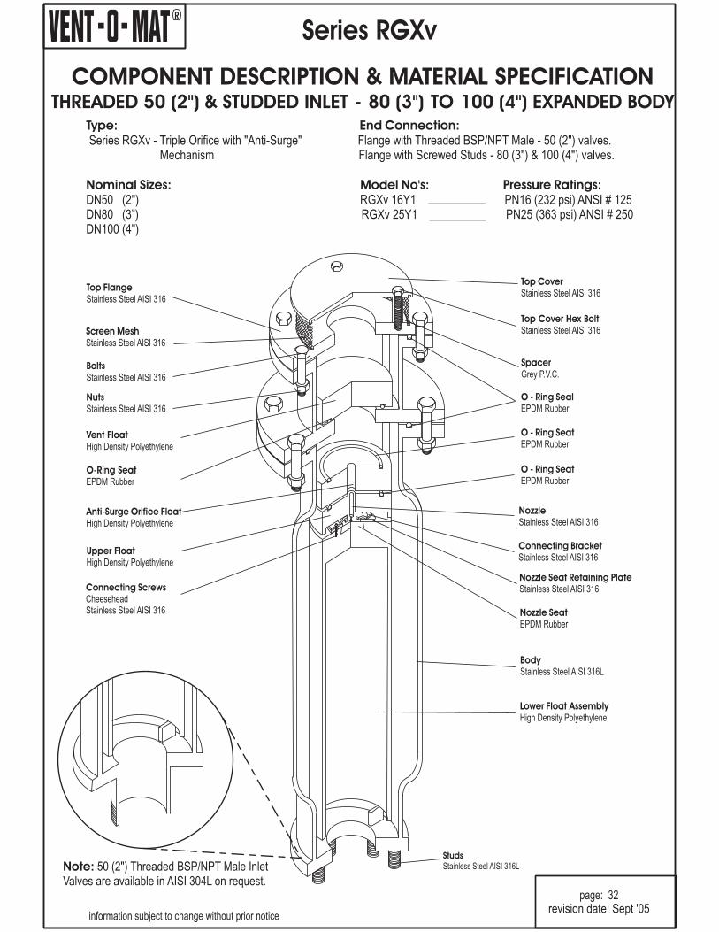
Series RGXv
Type: End Connection:
Nominal Sizes: Model No's: Pressure Ratings:
Series RGXv - Triple Orifice with "Anti-Surge"Mechanism
DN50 (2") RGXv 16Y1 PN16 (232 psi) ANSI # 125DN80 (3”) RGXv 25Y1 PN25 (363 psi) ANSI # 250DN100 (4
Flange with Threaded BSP/NPT Male - 50 (2") valves.Flange with Screwed Studs - 80 (3") & 100 (4") valves.
")
information subject to change without prior notice
page: 32
StudsStainless Steel AISI 316L
COMPONENT DESCRIPTION & MATERIAL SPECIFICATIONSTUDDED INLET - 80 (3") TO 100 (4THREADED 50 (2") & ") EXPANDED BODY
revision date: Sept '05
O - Ring SeatEPDM Rubber
Note: 50 (2Valves are available in AISI 304L on request.
") Threaded BSP/NPT Male Inlet

R
Top CoverStainless Steel AISI 316
SpacerGrey P.V.C.
Assembly ScrewsCheeseheadStainless Steel AISI 316
O - Ring SealEPDM Rubber
Top FlangeStainless Steel AISI 316
Screen MeshStainless Steel AISI 316
BoltsStainless Steel AISI 316
Vent FloatHigh Density Polyethylene
Upper FloatHigh Density Polyethylene
Nozzle Seat Retaining PlateStainless Steel AISI 316
Nozzle SeatEPDM Rubber
NutsStainless Steel AISI 316
O-Ring SeatEPDM Rubber
NozzleStainless Steel AISI 316
Anti-Surge Orifice FloatHigh Density Polyethylene
O - Ring SeatEPDM Rubber
Float ScrewStainless Steel AISI 316
Lower Float AssemblyHigh Density Polyethylene
Connecting ScrewsCheeseheadStainless Steel AISI 316
BodyStainless Steel AISI 316L
Series RGXv
Type: End Connection:
Nominal Sizes: Model No's: Pressure Ratings:
Series RGXv - Triple Orifice with "Anti-Surge"Mechanism.
DN150 (6") RGXv 10Y1 PN10 (145 psi) ANSI # 125DN200 (8")
Flange with Screwed Studs - 150 (6") & 200 (8") valves.
information subject to change without prior notice
page: 33
StudsStainless Steel AISI 316L
COMPONENT DESCRIPTION & MATERIAL SPECIFICATIONSTUDDED INLET - 150 (6") & 200 (8")
revision date: Sept '05
Valves are available in AISI 304L on request.
R
Top CoverStainless Steel AISI 316
SpacerGrey P.V.C.
Top Cover Hex BoltStainless Steel AISI 316
O - Ring SealEPDM Rubber
Top FlangeStainless Steel AISI 316
Screen MeshStainless Steel AISI 316
BoltsStainless Steel AISI 316
Upper FloatHigh Density Polyethylene
NozzleStainless Steel AISI 316
Nozzle SeatEPDM Rubber
NutsStainless Steel AISI 316
Vent FloatHigh Density Polyethylene
O-Ring SeatEPDM Rubber
Float ScrewStainless Steel AISI 316
Anti-Surge Orifice FloatHigh Density Polyethylene
O - Ring SeatEPDM Rubber
Nozzle Seat Retaining PlateStainless Steel AISI 316
Lower Float AssemblyHigh Density Polyethylene
Connecting ScrewsCheeseheadStainless Steel AISI 316
BodyStainless Steel AISI 316L
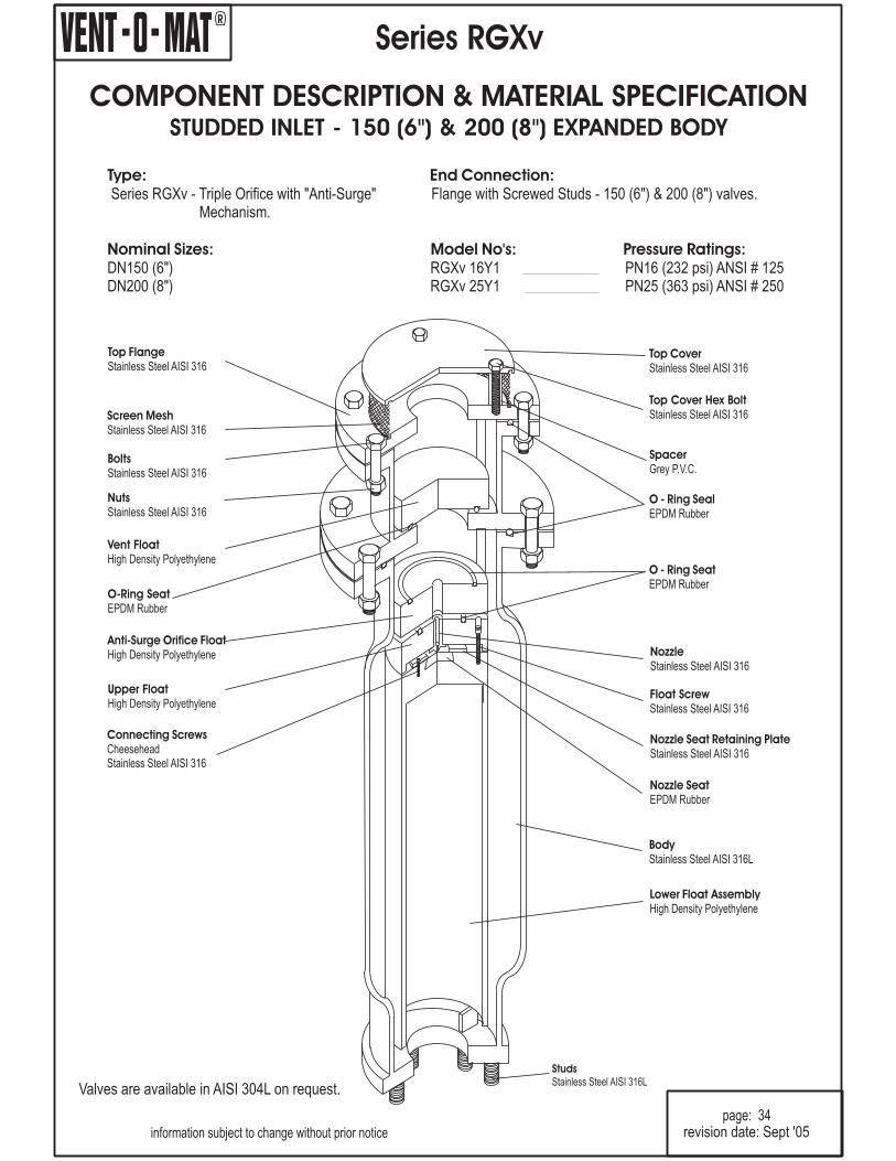
Series RGXv
Type: End Connection:
Nominal Sizes: Model No's: Pressure Ratings:
Series RGXv - Triple Orifice with "Anti-Surge"Mechanism.
DN150 (6") RGXv 16Y1 PN16 (232 psi) ANSI # 125DN200 (8") RGXv 25Y1 PN25 (363 psi) ANSI # 250
Flange with Screwed Studs - 150 (6") & 200 (8") valves.
information subject to change without prior noticepage: 34
StudsStainless Steel AISI 316L
COMPONENT DESCRIPTION & MATERIAL SPECIFICATIONSTUDDED INLET - 150 (6") & 200 (8") EXPANDED BODY
revision date: Sept '05
Valves are available in AISI 304L on request.
R
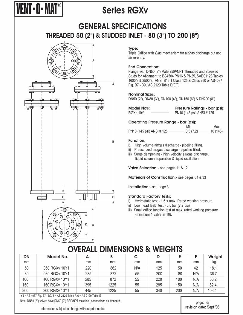
Type:
End Connection:
Nominal Sizes:
Model No's: Pressure Ratings - bar (psi):
Operating Pressure Range - bar (psi):
Function:
Valve Selection:-
Materials of Construction:-
Installation:-
Standard Factory Tests:
Triple Orifice with mechanism for air/gas discharge but notair re-entry.
DN50 (2"), DN80 (3"), DN100 (4"), DN150 (6") & DN200 (8")
RGXb 10Y1 PN10 (145 psi) ANSI # 125
Min Max.PN10 (145 psi) ANSI # 125 0.5 (7.2) 10 (145)
i) High volume air/gas discharge - pipeline filling.ii) Pressurized air/gas discharge - pipeline filled.iii) Surge dampening - high velocity air/gas discharge,
liquid column separation & liquid oscillation.
see pages 11 & 12
see pages 31 & 33
see page 3
i) Hydrostatic test - 1.5 x max. Rated working pressureii) Low head leak test - 0.5 bar (7,2 psi)iii) Small orifice function test at max. rated working pressure
(minimum 1 valve in 10).
Bias
Flange with DN50 (2") Male BSP/NPT Threaded and ScrewedStuds for Alignment to BS4504 PN16 & PN25, SABS1123 Tables1600/3 & 2500/3, ANSI B16.1 Class 125 & Class 250 or AS4087Fig. B7 - B9 / AS 2129 Table D/E/F.
Series RGXv
page: 35
information subject to change without prior notice
Note: DN50 (2") valves have DN50 (2") BSP/NPT male inlet connections as standard.
R
OVERALL DIMENSIONS & WEIGHTS
DE A
A
GENERAL SPECIFICATIONSTHREADED 50 (2 STUDDED INLET - 80 (3") TO 200 (8 )") & "
C
B
F
revision date: Sept '05
80 080 RGXv 10Y1 285 872 55 200 80 36.7N/A
100 100 RGXv 10Y1 285 872 55 220 100 36.2N/A
150 150 RGXv 10Y1 395 1225 55 285 150 82.4N/A
200 200 RGXv 10Y1 445 1225 55 340 200 103.4N/A
DN Model No. A B C D E F Weightmm mm mm mm mm mm kgmm
50 050 RGXv 10Y1 220 862 N/A 125 50 42 18.1
Y4 = AS 4087 Fig. B7 - B9, 5 = AS 2129 Table F, 6 = AS 2129 Table E

R
Type:
End Connection:
Nominal Sizes:
Model No's: Pressure Ratings - psi:
Operating Pressure Range - psi:
Function:
Valve Selection:-
Materials of Construction:-
Installation:-
Standard Factory Tests:
Triple Orifice with mechanism for air/gas discharge but notair re-entry.
DN50 (2"), DN80 (3"), DN100 (4"), DN150 (6") & DN200 (8")
RGXb 16Y1 16 (232 psi) ANSI # 125RGXb 25Y1 25 (363 psi) ANSI # 250
Min Max.16 (232 psi) ANSI # 125 0.5 (7.2) 16 (232)25 (363 psi) ANSI # 250 25 (363)
i) High volume air/gas discharge - pipeline fillingii) Pressurized air/gas discharge - pipeline filled.iii) Surge dampening - high velocity air/gas discharge,
liquid column separation & liquid oscillation.
see pages 11 & 12
see pages 32 & 34
see page 3
i) Hydrostatic test -1.5 x max. rated working pressureii) Low head leak test - 0.5 bar (7.2 psi)iii) Small orifice function test at max. rated working pressure
(minimum 1 valve in 10).
Bias
Flange with DN50 (2") Male BSP/NPT Threaded and ScrewedStuds for Alignment to BS4504 PN16 & PN25, SABS1123 Tables1600/3 & 2500/3, ANSI B16.1 Class 125 & Class 250 or AS4087Fig. B7 - B9 / AS 2129 Table D/E/F.
0.5 (7.2)
Series RGXv
page: 36
information subject to change without prior notice
Note: DN50 (2") valves have DN50 (2") BSP/NPT male inlet connections as standard.
R
OVERALL DIMENSIONS & WEIGHTS
DE A
A
B
F C
GENERAL SPECIFICATIONSTHREADED 50 (2 STUDDED INLET - 80 (3") TO 200 (8") & ") EXPANDED BODY
revision date: Sept '05
80 080 RGXv 16Y1 285 872 55 200 80 44.5N/A
100 100 RGXv 16Y1 285 872 55 220 100 44N/A
150 150 RGXv 16Y1 395 1225 55 285 150 99N/A
200 200 RGXv 16Y1 445 1225 55 340 200 120N/A
DN Model No. A B C D E F Weightmm mm mm mm mm mm kgmm
50 050 RGXv 16Y1 220 862 N/A 125 50 42 25.5
80 080 RGXv 25Y1 285 872 55 200 80 N/A 44.5
100 100 RGXv 25Y1 285 872 55 220 100 N/A 44
150 150 RGXv 25Y1 395 1225 55 285 150 N/A 99
200 200 RGXv 25Y1 445 1225 55 340 200 N/A 120
50 050 RGXv 25Y1 220 862 N/A 125 50 42 25.5
Y4 = AS 4087 Fig. B7 - B9, 5 = AS 2129 Table F, 6 = AS 2129 Table E
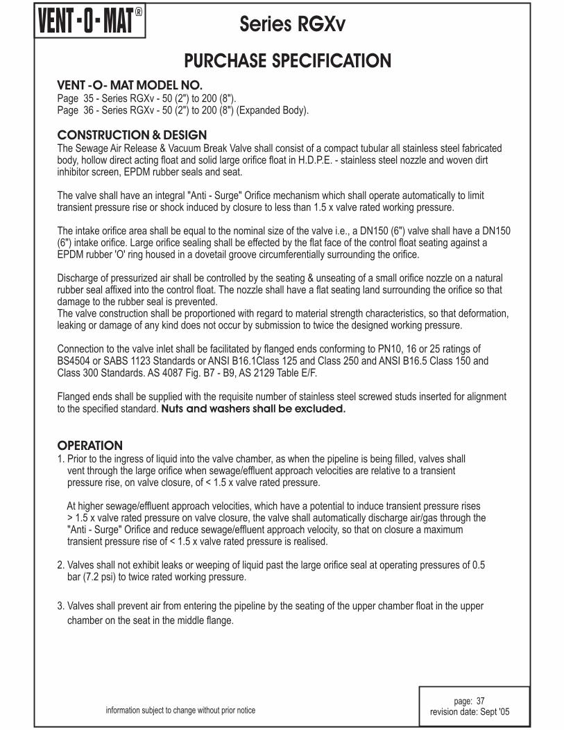
R
Series RGXv
PURCHASE SPECIFICATION
information subject to change without prior noticepage: 37
revision date: Sept '05
VENT -O- MAT MODEL NO.
CONSTRUCTION & DESIGN
OPERATION
Page 35 - Series RGXv - 50 (2") to 200 (8").Page 36 - Series RGXv - 50 (2") to 200 (8") (Expanded Body).
The Sewage Air Release & Vacuum Break Valve shall consist of a compact tubular all stainless steel fabricatedbody, hollow direct acting float and solid large orifice float in H.D.P.E. - stainless steel nozzle and woven dirtinhibitor screen, EPDM rubber seals and seat.
The valve shall have an integral "Anti - Surge" Orifice mechanism which shall operate automatically to limittransient pressure rise or shock induced by closure to less than 1.5 x valve rated working pressure.
The intake orifice area shall be equal to the nominal size of the valve i.e., a DN150 (6") valve shall have a DN150(6") intake orifice. Large orifice sealing shall be effected by the flat face of the control float seating against aEPDM rubber 'O' ring housed in a dovetail groove circumferentially surrounding the orifice.
Discharge of pressurized air shall be controlled by the seating & unseating of a small orifice nozzle on a naturalrubber seal affixed into the control float. The nozzle shall have a flat seating land surrounding the orifice so thatdamage to the rubber seal is prevented.The valve construction shall be proportioned with regard to material strength characteristics, so that deformation,leaking or damage of any kind does not occur by submission to twice the designed working pressure.
1. Prior to the ingress of liquid into the valve chamber, as when the pipeline is being filled, valves shallvent through the large orifice when sewage/effluent approach velocities are relative to a transientpressure rise, on valve closure, of < 1.5 x valve rated pressure.
At higher sewage/effluent approach velocities, which have a potential to induce transient pressure rises> 1.5 x valve rated pressure on valve closure, the valve shall automatically discharge air/gas through the"Anti - Surge" Orifice and reduce sewage/effluent approach velocity, so that on closure a maximumtransient pressure rise of < 1.5 x valve rated pressure is realised.
2. Valves shall not exhibit leaks or weeping of liquid past the large orifice seal at operating pressures of 0.5bar (7.2 psi) to twice rated working pressure.
3. Valves shall prevent air from entering the pipeline by the seating of the upper chamber float in the upper
chamber on the seat in the middle flange.
Nuts and washers shall be excluded.
Connection to the valve inlet shall be facilitated by flanged ends conforming to PN10, 16 or 25 ratings ofBS4504 or SABS 1123 Standards or ANSI B16.1Class 125 and Class 250 and ANSI B16.5 Class 150 andClass 300 Standards. AS 4087 Fig. B7 - B9, AS 2129 Table E/F.
Flanged ends shall be supplied with the requisite number of stainless steel screwed studs inserted for alignmentto the specified standard.

Note:
All air release valves supplied shall be subjected to the following testing procedures intheorder laiddown:
IMPORTANT NOTE:
1. DN250 (10") and DN300 (12") valves are available on request.
A) A high pressure strength and leak test whereby the valve is filled with water and pressurized to 1.5 x therated working pressure which shall be held for a period of 2 minutes.Any leaking, weeping or sweating shallbe reason for rejection.
B) A low head leak test whereby the valve is filled with water and pressurized to a maximum of 0.5 bar (7.2 psi)using a visible water column connected to the test rig. The valve shall be rejected if leak tightness is notmaintained for 2 minutes
C) Every tenth air release valve of the same size and pressure rating must be subjected to a small orificefunction test - "DROP TEST" - whereby the valve is filled with water, pressurized to above rated workingpressure and isolated from the test rig by closure of an isolating valve.Achamber in the test rig immediatelyprior to the isolating valve must be filled with compressed air at a pressure equal to that being maintained inthe air release valve. The isolating valve is then opened so as to allow the air to rise in the air release valvewithout the pressure dropping lower than 2 - 3 bar (29 - 44 psi) above rated working pressure of the airrelease valve. The "DROP TEST" is then carried out by slowly bleeding off the pressure through a suitablecock until rated working pressure is reached and the float drops away from the orifice to allow discharge.Failure of the air release valve to function in the manner described will be reason for rejection.
On request the manufacturer shall provide batch certificates of test compliance which shall be crossreferenced to serial numbers indelibly marked onto the identity label of each valve.
It is impossible to inject air into an incompressible liquid, air injection can only beachieved if the liquid can be displaced which implies that the pressure in the test rig must be reduced toatmospheric, and absolutely nothing is proven by discharge through the small orifice of the air release valve atatmospheric pressure. "DROPTESTING" in this manner is not acceptable.
R
Series RGXb & RGXv
ORDERING GUIDE
information subject to change without prior notice
page: 38
VALVE SERIES No.
ANTI SHOCK ORIFICE:
SPECIAL APPLICATION:BIAS AIR IN bBIAS AIR OUT v
0 5 0 R G X v 1 0 2 1VALVE TYPE:
DOUBLE ACTING 1
revision date: Sept '05
VALVE PRESSURE RATING:
PN10 (145 psi) 1 0
PN16 (232 psi) 1 6
PN25 (363 psi) 2 5
VALVE END CONNECTION:THREADED - BSP MALE 1THREADED - NPT MALE 2STUDDED FLANGED - Bs4504 or SABS 1123 0STUDDED FLANGED - ANSI B16.1 & B16.5 3STUDDED FLANGED - AS 4087 Fig. B7 - B9 4AS 2129 Table F 5AS 2129 Table E 6
VALVE SIZE:
Dn50 (2") - 0 5 0
DN80 (3") - 0 8 0
DN100 (4") - 1 0 0
DN150 (6") - 1 5 0DN200 (8") - 2 0 0

R
Series RGX
Complete the form below for any additional information and fax/post to:
Vent-O-Mat Australia (Pty) Ltd
P.O. Box 156
Seven Hills, NSW 1730
Sydney, Australia
Tel: +61 2 8814 9699 Fax: +61 2 8814 9666
E Mail: [email protected] Web site: www.ventomat.com
Company Name:
Postal Address:
Postal Code: Country:
Tel: Fax:
Contact Name: Title:
Comments:
VENT-O-MAT Series RBX Air Release & Vacuum Break Valves
VENT-O-MAT Series RC Air Release & Vacuum Break Valves
High Performance Endline Level Control Valves
®
®
®
compact Stainless Steel single chamber design with integral "Anti-Shock" surge dampeningmechanism.
cast air valve for irrigation and small reticulation systems.
glass reinforced polypropylene CATT air valve for industrial, irrigation and small reticulationsystems.
end line valve with cushioned closing characteristics for level control in tanks and reservoirs.
LevelDex
VENT-O-MAT Series RPS Air Release & Vacuum Break Valves®
VENT-O-MAT Series RBXc Air Release & Vacuum Break Valves®
compact cast single chamber design with integral "Anti-Shock" surge dampening mechanismin an economical cast ductile iron construction.
Products you are interested in: