
Series: OEM300 - micronor-ag.ch · PDF file5.2 ISO 9001:2008 Certificate ... 9222.10.216 Fiber...
41
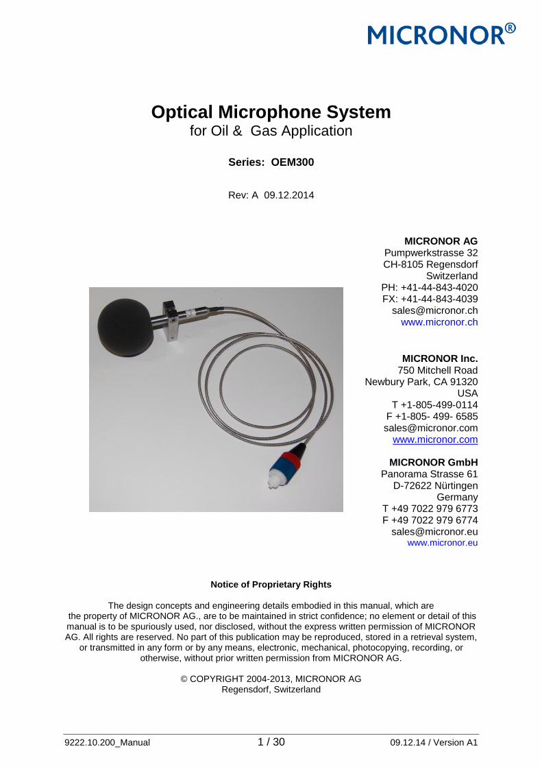
9222.10.200_Manual 1 / 30 09.12.14 / Version A1 Optical Microphone System for Oil & Gas Application Series: OEM300 Rev: A 09.12.2014 MICRONOR AG Pumpwerkstrasse 32 CH-8105 Regensdorf Switzerland PH: +41-44-843-4020 FX: +41-44-843-4039 [email protected] www.micronor.ch MICRONOR Inc. 750 Mitchell Road Newbury Park, CA 91320 USA T +1-805-499-0114 F +1-805- 499- 6585 [email protected] www.micronor.com MICRONOR GmbH Panorama Strasse 61 D-72622 Nürtingen Germany T +49 7022 979 6773 F +49 7022 979 6774 [email protected] www.micronor.eu Notice of Proprietary Rights The design concepts and engineering details embodied in this manual, which are the property of MICRONOR AG., are to be maintained in strict confidence; no element or detail of this manual is to be spuriously used, nor disclosed, without the express written permission of MICRONOR AG. All rights are reserved. No part of this publication may be reproduced, stored in a retrieval system, or transmitted in any form or by any means, electronic, mechanical, photocopying, recording, or otherwise, without prior written permission from MICRONOR AG. © COPYRIGHT 2004-2013, MICRONOR AG Regensdorf, Switzerland
Transcript of Series: OEM300 - micronor-ag.ch · PDF file5.2 ISO 9001:2008 Certificate ... 9222.10.216 Fiber...
9222.10.200_Manual 1 / 30 09.12.14 / Version A1
Optical Microphone System for Oil & Gas Application
Series: OEM300
Rev: A 09.12.2014
MICRONOR AG Pumpwerkstrasse 32 CH-8105 Regensdorf
Switzerland PH: +41-44-843-4020 FX: +41-44-843-4039
[email protected] www.micronor.ch
MICRONOR Inc.
750 Mitchell Road Newbury Park, CA 91320
USA T +1-805-499-0114
F +1-805- 499- 6585 [email protected]
www.micronor.com
MICRONOR GmbH Panorama Strasse 61
D-72622 Nürtingen Germany
T +49 7022 979 6773 F +49 7022 979 6774
[email protected] www.micronor.eu
Notice of Proprietary Rights
The design concepts and engineering details embodied in this manual, which are the property of MICRONOR AG., are to be maintained in strict confidence; no element or detail of this manual is to be spuriously used, nor disclosed, without the express written permission of MICRONOR AG. All rights are reserved. No part of this publication may be reproduced, stored in a retrieval system,
or transmitted in any form or by any means, electronic, mechanical, photocopying, recording, or otherwise, without prior written permission from MICRONOR AG.
© COPYRIGHT 2004-2013, MICRONOR AG
Regensdorf, Switzerland

9222.10.200_Manual 2 / 30 09.12.14 / Version A1
Revision History: Date Revision Modification
09.12.2014 Rev: A Created by M. Zürcher / checked by J. Kälin

9222.10.200_Manual 3 / 30 09.12.14 / Version A1
Content:
1. Product description - overview ................................................................................. 4
1.1 Parameter Specification ...................................................................................... 4
1.2 Product Application ...................................................................................................... 5
2. System components ..................................................................................................... 6
2.1 PNR: 9222.10.255 Remote unit OEM300 ........................................................ 6
2.1.1 High Pass Filter Mode for 22dB noise reduction .................................. 7
2.2 PNR: 9222.10.216 Fiber Optic Microphone ........................................................ 8
2.2.1 Test Certificate ............................................................................................................ 8
2.3 PNR: 9222.10.290, 291 and 292 Extension cable BRUsteel ..................... 9
2.4 PNR: 9222.10.225 Extension cable Break out 24 Fiber ............................ 10
2.5 PNR: 9222.10.288 Cable winder-reel ............................................................. 11
2.6 Accessories ......................................................................................................... 11
2.6.1 PNR: 9222.10.262 Windscreen ACO WS7 ........................................... 12
2.6.2 PNR: 9222.10.261 Microphone Holder ................................................. 13
2.6.3 PNR: 9222.10.280 Rack for Remote units ......................................... 14
2.6.4 PNR: 9222.10.225 Duplex Patch Cable ................................................ 14
3 Drawings ........................................................................................................................ 15
3.5 PNR: 9222.10.255 Remote Unit ...................................................................... 15
3.6 PNR: 9222.10.216 Microphone OEM300 2m cable ..................................... 15
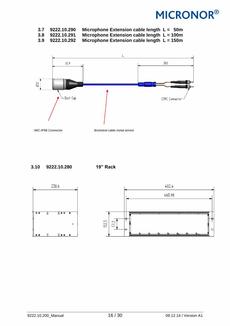
3.7 9222.10.290 Microphone Extension cable length L = 50m .................... 16
3.8 9222.10.291 Microphone Extension cable length L = 100m .................... 16
3.9 9222.10.292 Microphone Extension cable length L = 150m .................... 16
3.10 9222.10.280 19” Rack ........................................................................................ 16
3.11 9222.10.200 Duplex Patch cable ......................................................... 17
4. How to install the system ............................................................................................. 17
4. How to install the system ........................................................................................... 18
4.1 Overview .................................................................................................................... 18
4.2 Attention ..................................................................................................................... 18
4.3 Install the microphone ........................................................................................... 19
4.4 Install the BRUsteel cable ..................................................................................... 19
4.5 Install the 19” rack ................................................................................................... 20
4.6 Install the remote units into the 19” rack .......................................................... 20
4.7 Connect the Microphone OEM300 to the BRUsteel cable. ........................... 21
4.8 Connect the remote unit OEM300 ....................................................................... 22
4.10 Field adjustment .................................................................................................... 23
5. Attachments .................................................................................................................... 24
5.1 Certificate of the Piston phone ........................................................................ 25
5.2 ISO 9001:2008 Certificate .................................................................................. 25
5.3 Each Remote unit is delivered with a Acceptance Test Report ATR ... 26
5.4 Each Microphone is delivered with a Acceptance Test Report ATR .... 27
5.5 EC Declaration and CE mark ............................................................................ 29
5.6 Simples apparatures ........................................................................................... 29
9222.10.200_Manual 4 / 30 09.12.14 / Version A1
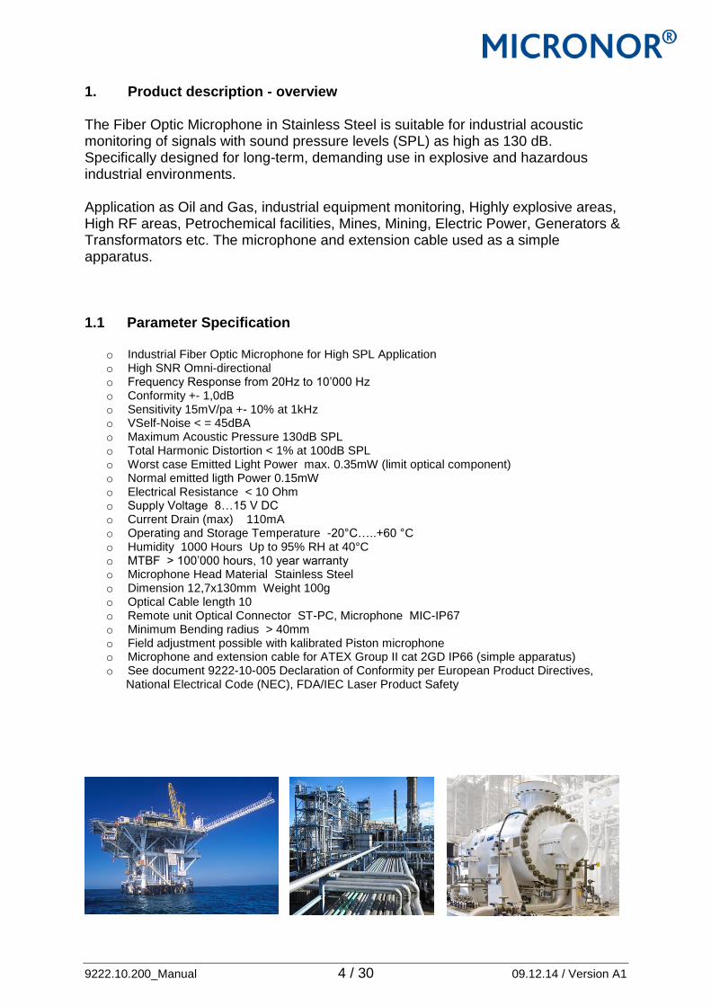
1. Product description - overview The Fiber Optic Microphone in Stainless Steel is suitable for industrial acoustic monitoring of signals with sound pressure levels (SPL) as high as 130 dB. Specifically designed for long-term, demanding use in explosive and hazardous industrial environments. Application as Oil and Gas, industrial equipment monitoring, Highly explosive areas, High RF areas, Petrochemical facilities, Mines, Mining, Electric Power, Generators & Transformators etc. The microphone and extension cable used as a simple apparatus. 1.1 Parameter Specification
o Industrial Fiber Optic Microphone for High SPL Application o High SNR Omni-directional o Frequency Response from 20Hz to 10’000 Hz o Conformity +- 1,0dB o Sensitivity 15mV/pa +- 10% at 1kHz o VSelf-Noise < = 45dBA o Maximum Acoustic Pressure 130dB SPL o Total Harmonic Distortion < 1% at 100dB SPL o Worst case Emitted Light Power max. 0.35mW (limit optical component) o Normal emitted ligth Power 0.15mW o Electrical Resistance < 10 Ohm o Supply Voltage 8…15 V DC o Current Drain (max) 110mA o Operating and Storage Temperature -20°C…..+60 °C o Humidity 1000 Hours Up to 95% RH at 40°C o MTBF > 100’000 hours, 10 year warranty o Microphone Head Material Stainless Steel o Dimension 12,7x130mm Weight 100g o Optical Cable length 10 o Remote unit Optical Connector ST-PC, Microphone MIC-IP67 o Minimum Bending radius > 40mm o Field adjustment possible with kalibrated Piston microphone o Microphone and extension cable for ATEX Group II cat 2GD IP66 (simple apparatus) o See document 9222-10-005 Declaration of Conformity per European Product Directives, National Electrical Code (NEC), FDA/IEC Laser Product Safety

9222.10.200_Manual 5 / 30 09.12.14 / Version A1
1.2 Product Application The OEM300 series Fiber Optic Microphone System consists of a passive Microphone and active remote unit which are connected via a duplex multimode fiber optic link: Remote Modul Extension Cable Fiber optic Microphone
1.3 Product Codes
Order codes: Part number Description 9222.10.216 Fiber optic Microphone for Atex with 2m cable and MIC-IP67 connector 9222.10.225 FO cable with 24 single fibre 62,5/125 9222.10.230 FO duplex patch cable 2m ST/PC Connector 62,5/125 9222.10.255 Remote unit for one optical Microphone, rack solution 9222.10.290 BRUsteel extension cable 50m 9222.10.291 BRUsteel extesnion cable 100m 9222.10.292 BRUsteel extesnion cable 150m Accessories 9222.10.261 Microphone holder 9222.10.262 Windscreen 9222.10.267 ST-PC Connector set SM prepolished PC strain relief version 9222.10.280 Rack mounted 19" Cabinets cage for 8 Remote units 9222.10.288 Cable winder-reel for BRUsteel cable Set PNR
9222.10.212 incl 9222.10.216 + 9222.10.290 9222.10.213 incl 9222.10.216 + 9222.10.291 9222.10.214 incl 9222.10.216 + 9222.10.292
9222.10.260 incl 9222.10.261 + 9222.10.262
EX Process AREA SAFETY ROOM
Simple Apparatus

9222.10.200_Manual 6 / 30 09.12.14 / Version A1
2. System components 2.1 PNR: 9222.10.255 Remote unit OEM300 Single Channel Electro-Optic Remote unit for fiber optical Microphones. It features two analog outputs REC and PHONE. Phone with volume control for headphones, another with fixed gain for monitoring equipment. One pair of ST-Style fiber optic connectors, two 3.5mm sockets, one for analog output, another for headphones, green LED voltage indicator shows power on status. DSP 4 step switch provides a high pass filter for 0,4,16, and 22dB of real-time ambient noise removal. The unit is powered with 12VDC.
Technical Specifications remote unit: Signal Output Sensitivity 15mV/pa +- 10% at 1kHz Supply Voltage 12 VDC Current Drain 250 mA Power supply Connector Phönix Headphone Output PHONE Mono Line Output REC Yes Adjustable Gain Range 45 dB DSP Latency at 16 kHz 10ms Operating Temperature -20°C to 60°C Box Material Anodized Aluminium Weight 400g Optical connector 2 x ST Field adjustable yes CE – conform EN 61000-6-1, EN 61000-6-3, EN 61000-6-4
Filter
Volume
Status LED
Power switch
Recorder Jack 3.5mm Plug
Phone Jack 3.5mm Plug
Optical Input (STPC)

9222.10.200_Manual 7 / 30 09.12.14 / Version A1
2.1.1 High Pass Filter Mode for 22dB noise reduction
The modul have a opticlear DSP algorithm for minimization of low frequency loss by using adaptive filter, spectral gain calculation, noise estimator and refined speech detector DSP brings ultimate hardware performance for advanced speech enhancement in real-time monitoring applications. DSP enables noise reduction in 4 steps switch 0, 4,16, 22dB. Using state-of-the-art, single noise reduction algorithm to remove noise from the desired speech signals. DSP enables very high quality restoration of the original speech signal, with minimal residual artefacts. Signal processing is modelled on actual properties of human speech and hearing, enabling extremely fast adaptive filtering for changing noise conditions. DSP eliminates common processing artefacts, such as ringing and musical noise, when filtering masked or low amplitude speech signals. DSP is a particularly suiyable for body-worm and mobile surveillance applications. Simply to improve speech significantly.

9222.10.200_Manual 8 / 30 09.12.14 / Version A1
2.2 PNR: 9222.10.216 Fiber Optic Microphone The fibre optic Microphone made from stainless steel and steel armored cable with MR-IP67 Micronor Duplex connector. The microphone is in ATEX terms a simples apparatures. so the microphone an be installed in all EX-Environments. The max worst case optical power are 0.35mW max power of the optical component, normal used power 0.15mW.
Weight 200g Protection EN 60 529 / DIN 40050-9 IP 66 Shock DIN-IEC 68-2-27 2000 m/s2, 5ms Vibration DIN-IEC 68-2-6 200m/s2, 10…..1000Hz EX ATEX Group II cat 2GD
2.2.1 Test Certificate All microphone supplied with a test certificate.
Optical Connector cable steal armored Microphone head Dust cap

9222.10.200_Manual 9 / 30 09.12.14 / Version A1
2.3 PNR: 9222.10.290, 291 and 292 Extension cable BRUsteel The extension cable BRUsteel is special steel coated. The two 62,5/125 micron fibre are in a metal tube. The cable was special designed for Oil and Gas industry. The cable are available in length of PNR: 9222.10.290 for L= 50m, PNR: 9222.10.291 for L=100m and PNR: 9222.10.292 for L=150m. The cable is supplied on the cable winder-reel PNR 9222.10.288. During installation the cable like to be independently so the cable winder is very useful. Start do draw the fiber from the microphone side and draw carfuly meter by meter. Fix the cable with cable cord. Please use always dust cap to protect the fibre optical connector. The cable have on one side two ST-PC II and on the other side MIC-IP67 connector mounted.

9222.10.200_Manual 10 / 30 09.12.14 / Version A1
2.4 PNR: 9222.10.225 Extension cable Break out 24 Fiber The extension cable Bundle type 150m long with open end release 24 fibre. Type simular to SLO-FR-A1 from Cavicel galvanized steel armored cable, inner sheath LSZH and mud resistant.

9222.10.200_Manual 11 / 30 09.12.14 / Version A1
2.5 PNR: 9222.10.288 Cable winder-reel The BRUsteel cable is winde on the cable winder-reel these is very importand for transportation and installation.
2.6 Accessories
9222.10.200_Manual 12 / 30 09.12.14 / Version A1
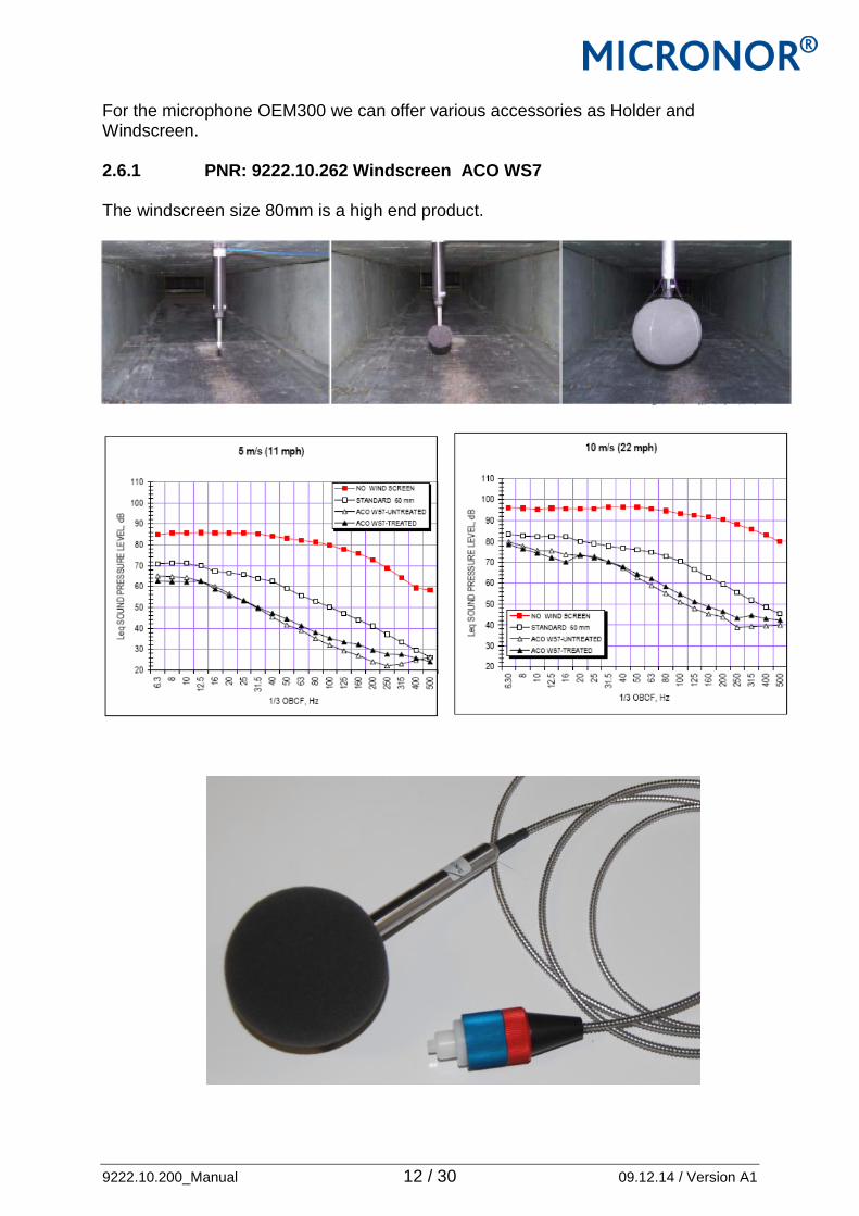
For the microphone OEM300 we can offer various accessories as Holder and Windscreen. 2.6.1 PNR: 9222.10.262 Windscreen ACO WS7 The windscreen size 80mm is a high end product.

9222.10.200_Manual 13 / 30 09.12.14 / Version A1
2.6.2 PNR: 9222.10.261 Microphone Holder The holder can support the microphone and mount on different positions.

9222.10.200_Manual 14 / 30 09.12.14 / Version A1
2.6.3 PNR: 9222.10.280 Rack for Remote units These is a 19” Rack slot for 8 OEM300 Remote modules PNR 9222.10.255. 2.6.4 PNR: 9222.10.225 Duplex Patch Cable The duplex patch cable is used to connect the BRUsteel cable or to patch on the central office. The cable mounted with two ST PC II conenctors. The fiber are Multimode 62,5/125 micron. Zip cord version 2m long.

9222.10.200_Manual 15 / 30 09.12.14 / Version A1
3 Drawings
3.5 PNR: 9222.10.255 Remote Unit
3.6 PNR: 9222.10.216 Microphone OEM300 2m cable
9222.10.200_Manual 16 / 30 09.12.14 / Version A1
3.7 9222.10.290 Microphone Extension cable length L = 50m 3.8 9222.10.291 Microphone Extension cable length L = 100m 3.9 9222.10.292 Microphone Extension cable length L = 150m
MIC-IP68 Connector Bruhsteel cable metal armed
3.10 9222.10.280 19” Rack

9222.10.200_Manual 17 / 30 09.12.14 / Version A1
3.11 9222.10.200 Duplex Patch cable 4. How to install the system lkjshfköjAIPUFGDADF

9222.10.200_Manual 18 / 30 09.12.14 / Version A1
4. How to install the system 4.1 Overview The MICRONOR OEM300 Fibre optical Microphone system is need a Remote unit extension cable BRUsteel and the fibre optical microphone. The microphone and the extension cable you can install in the harsh and EX environment. The remote module in the safety room. Remote Modul Extension Cable Fiber optic Microphone
4.2 Attention For installation of the fiber optical cable please respect the following Attention/rules. Please note when installing bending radius and stress on the cable. The optical fibers should be treated carefully, and should not be sharply. If bending of fibers is required, it is imperative that a minimum radius of 80mm be maintained at all times. Failure to do so can result in fiber optic breakage, rendering the unit permanently inoperable. The fiber have to fix a good as possible, fiber movement can generate noise.
EX Process AREA SAFETY ROOM
Simple Apparatus
9222.10.200_Manual 19 / 30 09.12.14 / Version A1
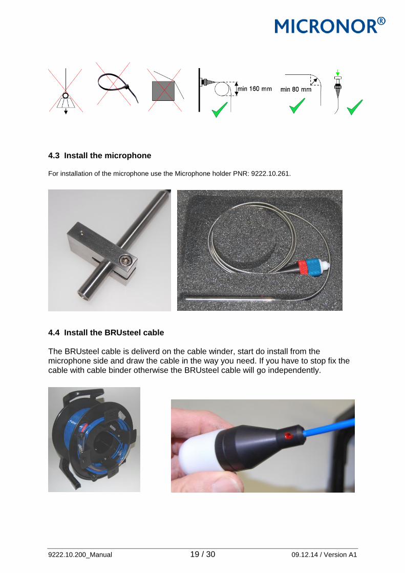
4.3 Install the microphone For installation of the microphone use the Microphone holder PNR: 9222.10.261.
4.4 Install the BRUsteel cable The BRUsteel cable is deliverd on the cable winder, start do install from the microphone side and draw the cable in the way you need. If you have to stop fix the cable with cable binder otherwise the BRUsteel cable will go independently.
9222.10.200_Manual 20 / 30 09.12.14 / Version A1
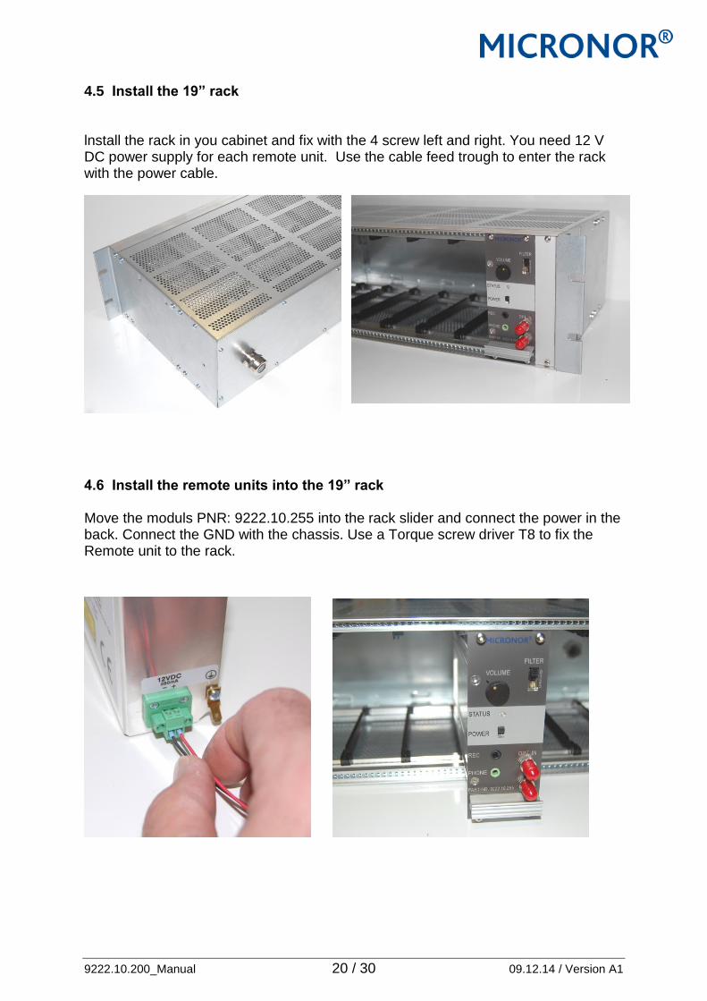
4.5 Install the 19” rack lnstall the rack in you cabinet and fix with the 4 screw left and right. You need 12 V DC power supply for each remote unit. Use the cable feed trough to enter the rack with the power cable. 4.6 Install the remote units into the 19” rack Move the moduls PNR: 9222.10.255 into the rack slider and connect the power in the back. Connect the GND with the chassis. Use a Torque screw driver T8 to fix the Remote unit to the rack.

9222.10.200_Manual 21 / 30 09.12.14 / Version A1
4.7 Connect the Microphone OEM300 to the BRUsteel cable. Remove the dust cap from the MIC-IP67 connector and connect the two connector carefully. Place the dust cap on a place where you can find again in case you will disconnect the microphone later. Dust cap are for optical installation very importend. 1. remove the dust cap from the cable the connector have a guide pin 2. remove the dust cap from the microphone connector.
you can see the hole for the guide pin move the two connector together 3. screw on the blue part, if the blue
part goes to strong turn on the red part the blue will be relased.
4. screw only on the red part to fix and look The connection is done and fixed.

9222.10.200_Manual 22 / 30 09.12.14 / Version A1
4.8 Connect the remote unit OEM300 The power 12 VDC is already connected, so you have only to connect the 2 ST PC connector and the fibrr optic link is o.k. Then connect a headphone on the PHONE output or connect direct to the REC Output your voice system. Connect the fibre optic ST PC II connectors Connect the REC Output
Use the Power ON switch the status LED shows GREEN, the system is ready.

9222.10.200_Manual 23 / 30 09.12.14 / Version A1
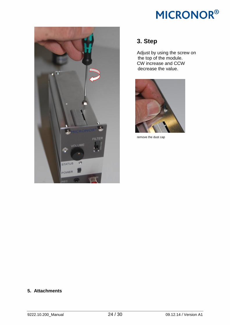
4.10 Field adjustment All MICRONOR Fibre optical Microphone are calibrated in the factory over the frequency range of 0………10’000 Hz. The remote unit is adjust with a reference microphone and a cable loss of 5dB. For the calibration we use a Piston phone of 123.98 dB and 251 Hz, adjustment value 475mV rms means, Sensitivity 15mV/1Pa = 94dB SPL. Self noise < 45 dBA
For the field installation the loss from the optical cable and connector higher or lower or same as 5dB so you can adjust if you like or need in the field. Use a Piston phone from B&K or simular company.
1. Step Move the microphone in the Piston Phone.
2. Step Measure the output level on the REC Output, Filter switch should in pos 0.
9222.10.200_Manual 24 / 30 09.12.14 / Version A1
3. Step Adjust by using the screw on the top of the module. CW increase and CCW decrease the value. remove the dust cap
5. Attachments

9222.10.200_Manual 25 / 30 09.12.14 / Version A1
5.1 Certificate of the Piston phone 5.2 ISO 9001:2008 Certificate

9222.10.200_Manual 26 / 30 09.12.14 / Version A1
5.3 Each Remote unit is delivered with a Acceptance Test Report ATR

9222.10.200_Manual 27 / 30 09.12.14 / Version A1
5.4 Each Microphone is delivered with a Acceptance Test Report ATR

9222.10.200_Manual 28 / 30 09.12.14 / Version A1
9222.10.200_Manual 29 / 30 09.12.14 / Version A1
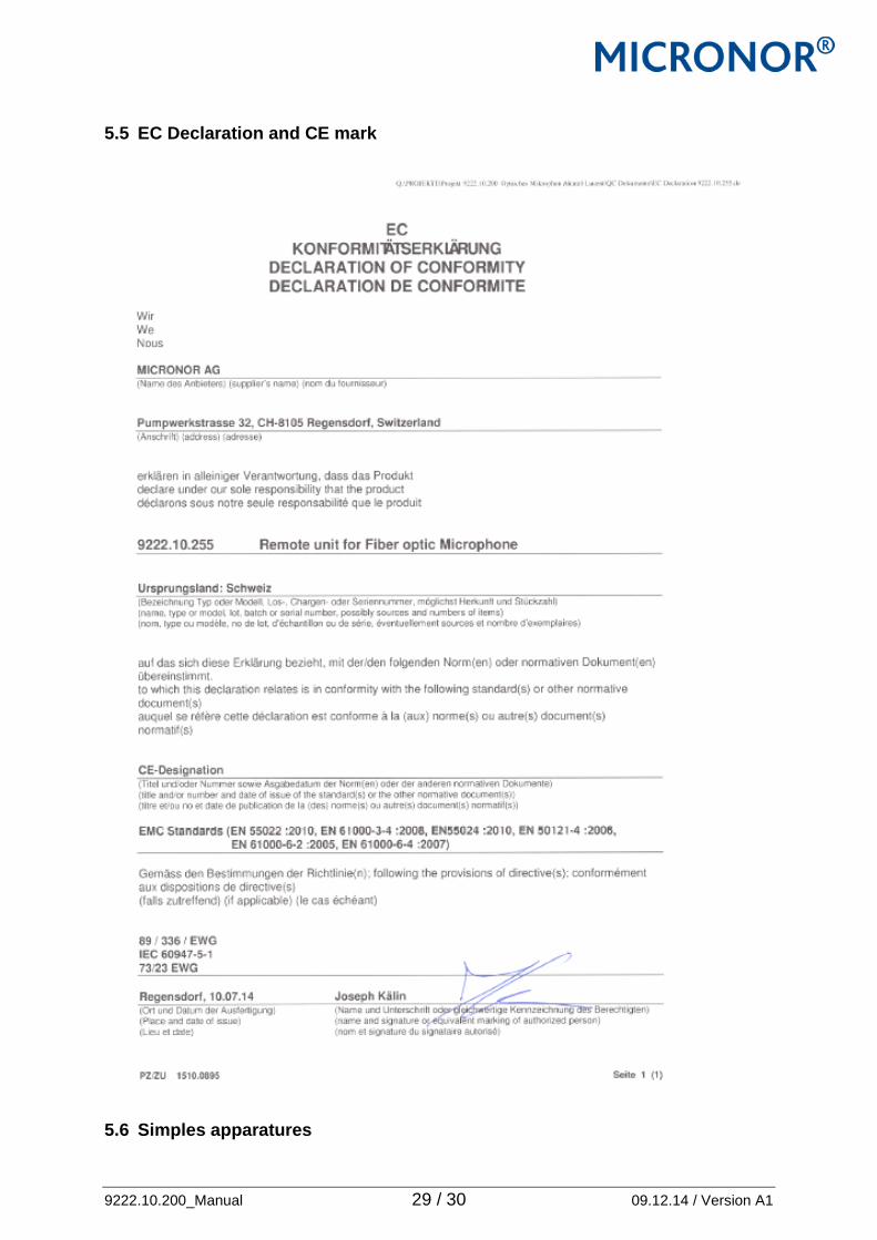
5.5 EC Declaration and CE mark 5.6 Simples apparatures
9222.10.200_Manual 30 / 30 09.12.14 / Version A1
DETAILED Declaration of Conformity
Per European Product Directives,
National Electrical Code (NEC), FDA/IEC Laser Product Safety
Product Description: OEM300 series Fiber Optic MICROPHONE System Affected Products: 9222.10.216 Fiber Optic passive MICROPHONE 9222.10.255 remote unit for the fiber optic microphone Document: 9222-10-005 Revision: Release A Dated: December 13, 2013 Number of Pages: 12 Document Outline 1. Product Overview 2. Risk Assessment by Category
2.1. Product Function (ISO13850) 2.2. Laser Safety (IEC 60825-1) 2.3. Explosive Atmospheres (NEC and ATEX 94/9/EC) 2.4. Functional Safety (ISO 13849-1) 2.5. Electromagnetic Compatibility (FCC and EMC 2004/108/EC) 2.6. Low Voltage Directive (LVD 2006/95/EC) 2.7. Control of Production 2.8. CE Mark
3. Product Marking 3.1. 9222.10.216 Fiber optic Microphone 3.2. 9222.10.255 Remote unit
4. User Obligations

9222.10.200_Manual 31 / 30 09.12.14 / Version A1
1. Product Overview The OEM300 series Fiber Optic Microphone System consists of a passive Microphone and active remote unit which are connected via a duplex multimode fiber optic link: Remote Modul Extension Cable Fiber optic Microphone
This document is the Detailed Report and Risk Assessment in support of Micronor's OEM300 series Declaration of Conformity Summary (document 9222-10-005) available on the company DB. The Summary and Detailed report establish the basis for the product markings and certifications described herein.
EX Process AREA SAFETY ROOM
Simple Apparatus
9222.10.200_Manual 32 / 30 09.12.14 / Version A1
2. Risk Assessment By Category 2.1 Product Function (ISO 13850) Reference: 1. ISO 13850, Safety of machinery - Principles for design, Edition 2006 Summary: Product meets the purpose and essential functionality of an microphone Device but the fiber optic sensor/interrogator aspect of the device excludes it from meeting all performance requirements more typical of a conventional electromechanical microphone. This product is designed for applications and environments where a conventional electromechanical microphone cannot be used.
Parameter Applies to All OEM300 Product Models
Functionality ISO 13850
NOTE: ISO 13850 defines the characteristics and requirements for a traditional electromechanical microphones. The OEM300 Fiber Optic microphone System borrows from the definition of purpose
and functionality only.
Analysis: ISO 13850 defines the functional requirements and design principles for device on machinery. The Micronor OEM300 Fiber Optic Microphone System functions similar to a standard electromechanical microphone. The passive optical sensor integrates a membrane actuator which controls an optical circuit or light path. As required by ISO 13850, the OEM300 microphone incorporates the same mechanical mechanism as a conventional. The optical transmit and receive paths comprise a duplex fiber link which is completed by connection to the remote unit. This module contains the system's optoelectronics as well as the electrical interface. The OEM300 Fiber Optic Microphone System is designed to be used where a conventional electromechanical microphone device cannot be used or is impractical to install. The passive optical microphone provides immunity to EMI/RFI/lightning, can be safely used in hazardous locations, and can operate over extremely long distances. Typical applications and environments where the sensor can be used:
Hazardous locations (gaseous or dust) such as mines, chemical plants, oil rigs and grain elevators
Long haul distances (up to 1000 meters) such as mines and remotely located machinery
Noisy electrical environments
High electromagnetic field environments such as MRI and other extreme EMF process applications
2.2 Laser Safety (IEC 60825-1) References: 1. IEC 60825-1, Safety of laser products - Part 1: Equipment classification, requirements and user's
guide, Edition 1.2, August 2001 2. IEC 60825-2, Safety of laser products - Part 2: Safety of optical fibre communication systems
(OFCS), Edition 2004+A2, October 2010 3. FDA, Code of Federal Regulations (CFR), Title 21, Chapter 1 - Food and Drug Administration -
Department of Health and Human Services, Subchapter J-Radiological Health, Parts 1000-1050
9222.10.200_Manual 33 / 30 09.12.14 / Version A1
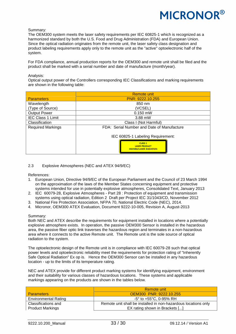
Summary: The OEM300 system meets the laser safety requirements per IEC 60825-1 which is recognized as a harmonized standard by both the U.S. Food and Drug Administration (FDA) and European Union. Since the optical radiation originates from the remote unit, the laser safety class designation and product labeling requirements apply only to the remote unit as the "active" optoelectronic half of the system. For FDA compliance, annual production reports for the OEM300 and remote unit shall be filed and the product shall be marked with a serial number and date of manufacture (month/year). Analysis: Optical output power of the Controllers corresponding IEC Classifications and marking requirements are shown in the following table:
Remote unit
Parameters PNR: 9222.10.255
Wavelength (Type of Source)
850 nm (VCSEL)
Output Power 0.150 mW
IEC Class 1 Limit 3.88 mW
Classification Class I (Not Harmful)
Required Markings FDA: Serial Number and Date of Manufacture
IEC 60825-1 Labeling Requirement:
2.3 Explosive Atmospheres (NEC and ATEX 94/9/EC) References: 1. European Union, Directive 94/9/EC of the European Parliament and the Council of 23 March 1994
on the approximation of the laws of the Member States concerning equipment and protective systems intended for use in potentially explosive atmospheres, Consolidated Text, January 2013
2. IEC 60079-28, Explosive Atmospheres - Part 28 : Protection of equipment and transmission systems using optical radiation, Edition 2 Draft per Project IEC 31/1043/CD, November 2012
3. National Fire Protection Association, NFPA 70, National Electric Code (NEC), 2014. 4. Micronor, OEM300 ATEX Evaluation, Document 9222-10-005, Revision A, August-2013 Summary: Both NEC and ATEX describe the requirements for equipment installed in locations where a potentially explosive atmosphere exists. In operation, the passive OEM300 Sensor is installed in the hazardous area, the passive fiber optic link traverses the hazardous region and terminates in a non-hazardous area where it connects to the active Remote unit. The Remote unit is the sole source of optical radiation to the system. The optoelectronic design of the Remote unit is in compliance with IEC 60079-28 such that optical power levels and optoelectronic reliability meet the requirements for protection rating of "Inherently Safe Optical Radiation" Ex op is. Hence the OEM300 Sensor can be installed in any hazardous location - up to the limits of its temperature rating. NEC and ATEX provide for different product marking systems for identifying equipment, environment and their suitability for various classes of hazardous locations. These systems and applicable markings appearing on the products are shown in the tables below.
Parameters
Remote unit
OEM300 PNR: 9222.10.255
Environmental Rating -5° to +55°C, 0-95% RH
Classifications and Product Markings
Remote unit shall be installed in non-hazardous locations only EX rating shown in Brackets [...]

9222.10.200_Manual 34 / 30 09.12.14 / Version A1
Inherently Safe Optical Radiation op is
Per IEC 60079-28
USA (NEC 500) (NEC 505)
[Class 1/2/3-All Divisions] [Zone 0/Zone 20]
EUROPE (ATEX 94/9/EC)) [Ex Op is I/II/III 55°C/T6 Ga/Ma/Da]
Applicable Directives
Microphone
OEM300 PNR: 9222.10.216 Where X is the pigtail length in meters
Environmental Rating -40° to +80°C, 0-95% RH
Explosive Environments Sensor can be installed and operated in applicable hazardous locations- mines, gaseous and dust
Inherently Safe Optical Radiation op is
Per IEC 60079-28
USA (NEC 500) (NEC 505)
Class 1/2/3-All Divisions Zone 0/Zone 20
EUROPE (ATEX 94/9/EC)) Ex Op is I/II/III 65°C/T6 Ga/Ma/Da
Analysis: IEC 60079-28 outlines the reliability and risk assessment required to evaluate the potential for hazardous energy output under normal operation as well as potential faults. Section 5.2.2.2 describes the methodology for identifying worst case faults of the optical driver and resulting worst case power output. This assessment was carried out and the Remote unit and overall system meets the requirements for Ex op is protection rating. The following table summarizes the analysis and testing applied to validate the optical output characteristics of the Remote unit which directly controls optical output of the system:
Parameters
Remote unit
PNR: 9222.10.255
IEC Radiated Power Limits for inherently safe optical radiation “op is” Group 1, All Atmospheres Group 2, All Atmospheres Group 3, For EPL=Da
15 mW 15 mW 35 mW
Wavelength Source Type Drive Method
850nm VCSEL
CW
Normal Output 0.15 mW
Worst Case Optical Power Output Optical Source/Driver Fault Testing per IEC 60079-28, Section 5.5.5.2, Test Condition 2
11 mW
Results Meets IEC 60079-28 requirements for Inherently Safe Optical Radiation Ex op is protection rating

9222.10.200_Manual 35 / 30 09.12.14 / Version A1
2.4 Functional Safety References: 1. ISO 13849-1, Safety of machinery — Safety-related parts of control systems - Part 1: General
principles for design, Edition 2006 + Techical Corrigendum 1, February 2009 2. ISO/TR 13849-100, Technical Report, Safety of machinery — Safety-related parts of control
systems - Part 100: Guidelines for the use and application of ISO 13849-1, First Edition, September 2000
3. MIL-HDBK-217, Military Handbook, Reliability Prediction of Electronic Equipment, Revision F + Notice 1 + Notice 2, February 1995
4. VITA 51.0, Reliability Prediction, June 2012 5. VITA 51.1, Reliability Prediction - MIL-HDBK-217 Subsidiary Specification, June 2008 6. Micronor, MR380 Bill Of Materials Spreadsheet, Revision B, September- 2013 Summary: The following table summarizes the Functional Safety attributes of the OEM300 Fiber Optic Microphone system:
Applicable Directives
System Configuration (Specified Remote unit + Fiber optic Microphone)
9222.10.216 + 9222.10.255
Functional Safety Category
Category 2 per ISO 13849-1
MTTF (for System) 35.4 years 3.10 E+05 hrs
MTTFd (for System) 70.8 years 6.20 E+05 hrs
Performance Level (PL) Safety Integrity Level (SIL)
PL=c SIL=1
Analysis: Per ISO 13849-1, the Microphone System is a support and information system.
Architecture of the MR250 System ISO 13849-1 requires a reliability assessment of MTTFd which is then used in the determination of PL and SIL values.. The method used is the Parts Count method per MIL-HDBK-217 Notice 2 supplemented by updates provided by VITA 51.0/51.1. For the optical sources used in the remote unit, we used MTTF data provided by the device manufacturers. Standard component failure factors from MIL-HDBK-217 Notice 2 were supplemented by: (1) updated reliability factors provided by VITA and (2) failure rate data provided by the optical source manufacturers. These resultant MTTF failure rate is provided in the summary table. For determination of MTTFd, Annex C of ISO 13849-1 provides guidance that typically only 50% of failures lead to a dangerous failure. Therefore MTTFd is calculated to be twice the MTTF value. MTTFd is then used to determine PL and SIL classifications per Table 1 of TR-62061. These values are provided in the summary table at the beginning of this section.
Fiber optic Microphone 100%
passive
Remote unit microphone Output Fiber optic Link

9222.10.200_Manual 36 / 30 09.12.14 / Version A1
2.5 Electromagnetic Compatibility References: 1 FCC, Code of Federal Regulations (CFR), Title 47-Telecommunication, Chapter 1-Federal
Communications Commission, Subchapter A-General, Part 15-Radio Frequency Devices, As of 27-September-2013
2 European Union, Directive 2004/108/EC on the approximation of the laws of the Member States relating to electromagnetic compatibility and repealing Directive 89/336/EEC, December 2004
3 IEC 61000-6-2, Electromagnetic compatibility (EMC), Part 6-2: General standards - Immunity for industrial environments, Edition 2.0, January 2005.
4 IEC 61000-6-4, Electromagnetic compatibility (EMC) - Part 6-4: Generic standards - Emission standard for industrial environments, Edition 2.0, July 2006
Summary: The OEM300 Microphone series is designed for use in Industrial Environments. EMC verification testing was performed on the 9222.10.255 Remote unit at an outside test lab. The OEM300 Sensors are not subject to EMC testing since they are passive devices. FCC Section 15.103b specifically exempts digital devices used exclusively in an electronics control system in an industrial plant.
Applicable Directives
Product Models
PNR: 9222.10.255 remote unit PNR: 9222.10.261 Microphone
Electromagnetic Compatibility
USA (FCC Part 15) Exempt
EUROPE (EMC 2004/108/EC)
Immunity: IEC 61000-6-2 Emissions: IEC 61000-6-4
Not applicable since passive device
Analysis: EMC verification testing to be completed before fixing of CE mark on 9222.10.255 Remote uit Controller. The OEM300 Sensors are not subject to EMC testing since they are passive devices. 2.6 Low Voltage Directive References: 1 European Union, Directive 2006/95/EC on the harmonization of the laws of the Member States
relating to electrical equipment designed for use within certain voltage limits, December 2006 2 IEC 61010-1, Safety requirements for electrical equipment for measurement, control and
laboratory use - Part 1: General requirements, Edition 3.0 + corrigendum 1 + 2, October 2013. Summary: The OEM300 series is designed for use in Industrial Environments. While the unit operates from 24 VDC, the relay contacts are specified for use up to 75 VAC and 50 VDC which exempts the unit from the Low Voltage Directive. General electrical safety principles and design assessment were carried out per IEC 61010-1
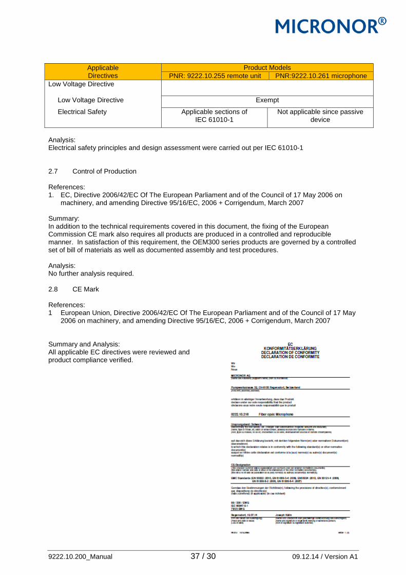
9222.10.200_Manual 37 / 30 09.12.14 / Version A1
Applicable Directives
Product Models
PNR: 9222.10.255 remote unit PNR:9222.10.261 microphone
Low Voltage Directive
Low Voltage Directive Exempt
Electrical Safety
Applicable sections of IEC 61010-1
Not applicable since passive device
Analysis: Electrical safety principles and design assessment were carried out per IEC 61010-1 2.7 Control of Production References: 1. EC, Directive 2006/42/EC Of The European Parliament and of the Council of 17 May 2006 on
machinery, and amending Directive 95/16/EC, 2006 + Corrigendum, March 2007 Summary: In addition to the technical requirements covered in this document, the fixing of the European Commission CE mark also requires all products are produced in a controlled and reproducible manner. In satisfaction of this requirement, the OEM300 series products are governed by a controlled set of bill of materials as well as documented assembly and test procedures. Analysis: No further analysis required. 2.8 CE Mark References: 1 European Union, Directive 2006/42/EC Of The European Parliament and of the Council of 17 May
2006 on machinery, and amending Directive 95/16/EC, 2006 + Corrigendum, March 2007 Summary and Analysis: All applicable EC directives were reviewed and product compliance verified.

9222.10.200_Manual 38 / 30 09.12.14 / Version A1
3. Product Markings The following are samples of product labels incorporating CE mark and all other applicable markings, class designations and warnings/cautions as described. 3.1 OEM300 optical microphone PNR: 9222.10.261
3.2 OEM300 Remote modul PNR: 9222.10.255
9222.10.200_Manual 39 / 30 09.12.14 / Version A1
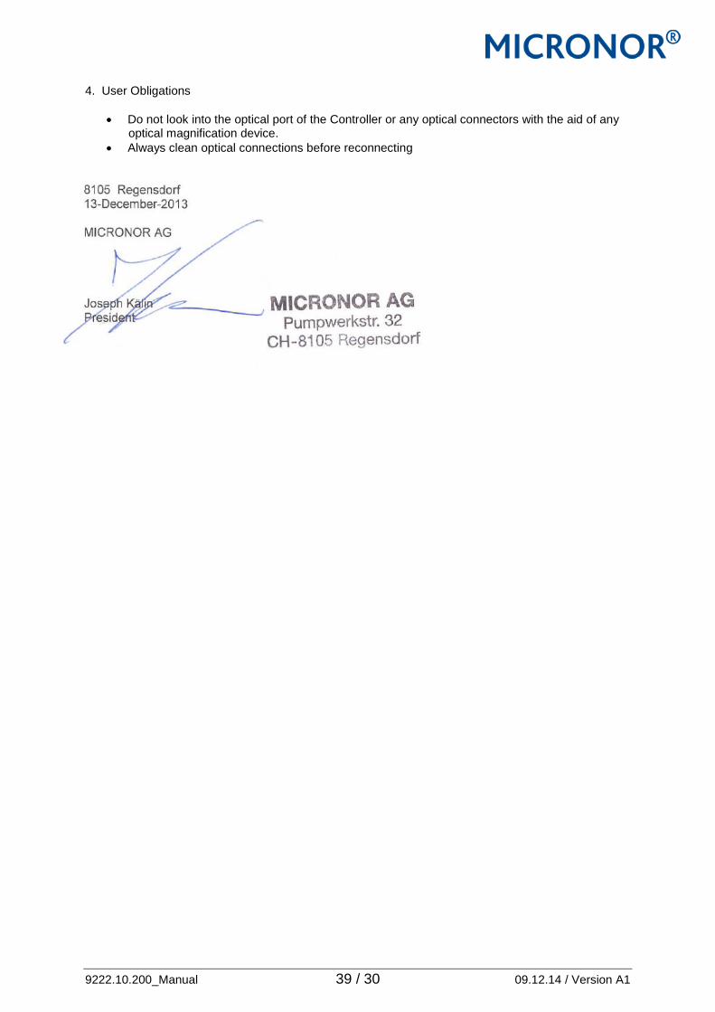
4. User Obligations
Do not look into the optical port of the Controller or any optical connectors with the aid of any optical magnification device.
Always clean optical connections before reconnecting 8105 Regensdorf 13-December-2013 MICRONOR AG Joseph Kälin President

9222.10.200_Manual 40 / 30 09.12.14 / Version A1
APPENDIX A: Terms and Acronyms ATEX Atmosphères Explosibles (Explosive Atmosphere). By ratifying the guideline 94/9/EC
on 23 March 1994 the European Parliament and the Council of the European Union started to harmonize the different national legislative provisions for the operation in areas with potentially explosive atmospheres. As an acronym, ATEX generally refers to the equipment regulations and standards established by EU directive 94/9/EC.
EN European Norm. European standards maintained by CEN (European Committee for
Standardization), CENELEC (European Committee for Electrotechnical Standardization) and ETSI (European Telecommunications Standards Institute):
FCC Federal Communications Commission (U.S. Government) FDA Food and Drug Administration (U.S. Government) IEC International Electrotechnical Commission. IEC is the international standards
commission that prepares and publishes all standards for electrical, electronic and related technologies. The worldwide organization promotes international unification of standards or norms. Its formal decisions on technical matters express, as nearly as possible, an international consensus. www.iec.ch
Inherently Safe Visible or infrared radiation that is incapable of producing sufficient energy under
normal or Optical specified fault conditions to ignite a specific hazardous atmospheric mixture. In this Radiation document, the term “intrinsically safe” is preferentially used because the industrial
community is more familiar with this terminology and less familiar with the new terminology developed with the very recent release (August 2006) of IEC 60079-28 Edition 1.0.
Intrinsically According to IEC 60079-28, the term “intrinsically safe” now specifically applies to
electrical Safe circuits while “inherently safe” applies to optical radiation. The terms are used
interchangeably in this document due to the user’s greater familiarity with “intrinsically safe”
ISO International Organization for Standardization. ISO is the world’s largest developer of
voluntary International Standards. www.iso.org LED Light Emitting Diode. A device used in a transmitter to convert information from
electrical to optical form. It typically has a large spectral width. A semiconductor device that emits light when forward biased.
MTTF Mean Time To Failure. Expectation of the mean time to failure. MTTFd Mean Time To Dangerous Failure. Expectation of the mean time to dangerous failure. PL Performance Level (PL) describe the targeted level of safety performance for a
given system. Standard ISO/EN 13849-1 defines five PL levels a-e. SIL Safety Integrity Level (SIL) is a relative level of risk-reduction provided by a safety
function, or to specify a target level of risk reduction..Standard IEC 61508 defines four levels SIL 1-4.
Simple As defined in the EC ATEX Guidelines, simple apparatuses (exclusions to the
Directive) are Apparatus “equipment and protective systems where the explosion hazard results exclusively
from the presence of explosive substances or unstable chemical substances.” In other words, under intended use and fault condition, the equipment have no known effective source of ignition.

9222.10.200_Manual 41 / 30 09.12.14 / Version A1
SOP Safe Optical Power. The SOP levels for various apparatus groups/temperature class combinations are provided in Table 2 of IEC 60079-28. By design, the MR310 CW optical output never exceeds the worst case SOP level.
VCSEL Vertical-Cavity Surface-Emitting Laser. A type of semiconductor laser with laser
beam emission perpendicular to the chip surface, contrary to conventional edge-emitting semiconductor lasers (also in-plane lasers) where laser light is emitted at one or two edges.