Series LLB Clean Air Module digital flow switch type RoHS · 2016-03-23 · Digital flow switch P1...
16
LLB3 Standard (100 L/min (ANR)) LLB4 High flow type (500 L/min (ANR)) F 1 F 1 LLB3 LLB4 How to Order Port size 1 2 2N ø10 One-touch fitting Rc 1/4 NPT 1/4 Filter F F1 With filter With filter with differential pressure indicator Note) Use a resin fitting (no metal) for Rc and NPT thread. Digital flow switch P1 P2 P3 P4 P5 P6 Nil Without digital flow switch NPN open collector 1 output + Analog output (1 to 5 V) PNP open collector 1 output + Analog output (1 to 5 V) NPN open collector 2 outputs PNP open collector 2 outputs NPN open collector 1 output + Analog output (4 to 20 mA) PNP open collector 1 output + Analog output (4 to 20 mA) Regulator Nil R R1 Without regulator With regulator With regulator + Pressure outlet port assembly ON/OFF valve V V1 V2 Nil Without ON/OFF valve With air operated With air operated flow adjuster Manual operation valve (with lever lock) Filter F With filter Restrictor S Nil Without restrictor With restrictor 1 3 3N ø12 One-touch fitting Rc 3/8 NPT 3/8 Port size Note) Use a resin fitting (no metal) for Rc and NPT thread. Note) For CE compliant models, digital flow switch type Clean Air Module Series LLB RoHS 1039
Transcript of Series LLB Clean Air Module digital flow switch type RoHS · 2016-03-23 · Digital flow switch P1...
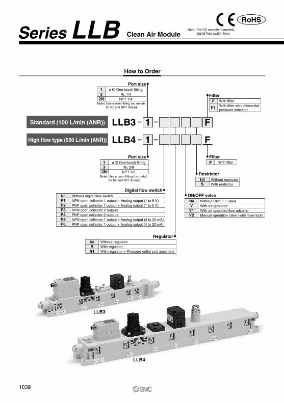
LLB3Standard (100 L/min (ANR))
LLB4High flow type (500 L/min (ANR))
F1
F1
LLB3
LLB4
How to Order
Port size12
2N
ø10 One-touch fittingRc 1/4
NPT 1/4Filter
F
F1
With filterWith filter with differential pressure indicator
Note) Use a resin fitting (no metal) for Rc and NPT thread.
Digital flow switch
P1P2P3P4P5P6
Nil Without digital flow switchNPN open collector 1 output + Analog output (1 to 5 V)PNP open collector 1 output + Analog output (1 to 5 V)NPN open collector 2 outputsPNP open collector 2 outputsNPN open collector 1 output + Analog output (4 to 20 mA)PNP open collector 1 output + Analog output (4 to 20 mA)
RegulatorNilRR1
Without regulatorWith regulatorWith regulator + Pressure outlet port assembly
ON/OFF valve
VV1V2
Nil Without ON/OFF valveWith air operatedWith air operated flow adjusterManual operation valve (with lever lock)
FilterF With filter
Restrictor
SNil Without restrictor
With restrictor
13
3N
ø12 One-touch fittingRc 3/8
NPT 3/8
Port size
Note) Use a resin fitting (no metal) for Rc and NPT thread.
Note) For CE compliant models, digital flow switch typeClean Air ModuleSeries LLB
RoHS
1039
PA
PB
0.36
0.52
0.47
0.41
0.52
0.63
0.57
0.59
0.61
0.57
0.63
0.76
0.33
0.39
0.44
0.50
0.41
0.46
0.52
0.51
0.28
0.34
0.23
0.19
0.84
1.18
1.10
1.09
1.35
1.44
1.44
1.36
1.70
1.61
1.62
1.87
0.90
1.15
1.16
1.41
1.07
1.32
1.33
1.71
0.82
1.07
0.81
0.49
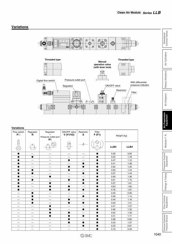
Variations
LLB3 LLB4
Flow switchP
RegulatorR
Regulator+
Pressure outlet portR1
ON/OFF valveV (V1/V2)
RestrictorS
FilterF (F1) Weight (kg)
Variations
Threaded type Threaded typeManual
operation valve(with lever lock)
Filter
With differentialpressure indicator
Restrictor
ON/OFF valve
Pressure outlet port
Regulator
Digital flow switch
Series LLBClean Air Module
1040
Air
Pre
par
atio
nE
qu
ipm
ent
Pre
ssur
e C
ontr
olE
quip
men
tF
low
Co
ntr
ol
Eq
uip
men
tPr
essu
re S
witc
hes/
Pres
sure
Sen
sors
Dir
ecti
on
alC
on
tro
l Val
ves
Air
Gri
pp
ers
Mo
du
lar
F. R
.Fi
ttin
gs &
Tub
ing
Air
Cyl
ind
ers
Rot
ary
Act
uato
rs
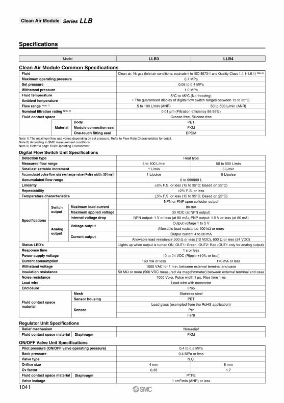
Specifications
Model LLB3 LLB4
0.7 MPa
0.05 to 0.4 MPa
1.0 MPa
Clean air, N2 gas (Inlet air conditions: equivalent to ISO 8573-1 and Quality Class 1.4.1-1.6.1) Note 3)
5°C to 45°C (No freezing)∗ The guaranteed display of digital flow switch ranges between 15 to 35°C.
0.01 µm (Filtration efficiency 99.99%)
Grease-free, Silicone-free
PBT
FKM
EPDM
5 to 100 L/min (ANR) 50 to 500 L/min (ANR)
Fluid
Maximum operating pressure
Set pressure
Withstand pressure
Fluid temperature
Ambient temperature
Flow range Note 1)
Nominal filtration rating Note 2)
Fluid contact space
Clean Air Module Common Specifications
Non-relief
FKM
Relief mechanism
Fluid contact space material Diaphragm
Regulator Unit Specifications
0.4 to 0.5 MPa
0.4 MPa or less
N.C.
PTFE
1 cm3/min (ANR) or less
4 mm
0.35
8 mm
1.7
Pilot pressure (ON/OFF valve operating pressure)
Back pressure
Valve type
Orifice size
Cv factor
Fluid contact space material
Valve leakageDiaphragm
ON/OFF Valve Unit Specifications
Digital Flow Switch Unit SpecificationsHeat type
0 to 999999 L
±5% F.S. or less (15 to 35°C: Based on 25°C)
±2% F.S. or less
±5% F.S. or less (15 to 35°C: Based on 25°C)
NPN or PNP open collector output
80 mA
30 VDC (at NPN output)
NPN output: 1 V or less (at 80 mA), PNP output: 1.5 V or less (at 80 mA)
Output voltage 1 to 5 V
Allowable load resistance 100 kΩ or more
Output current 4 to 20 mA
Allowable load resistance 300 Ω or less (12 VDC), 600 Ω or less (24 VDC)
Lights up when output is turned ON, OUT1: Green; OUT2: Red (OUT1 only for analog output)
1 s or less
12 to 24 VDC (Ripple ±10% or less)
1000 VAC for 1 min. between external terminal and case
50 MΩ or more (500 VDC measured via megohmmeter) between external terminal and case
1000 Vp-p, Pulse width 1 µs, Rise time 1 ns
Lead wire with connector
IP65
Stainless steel
PBT
Lead glass (exempted from the RoHS application)
Ptlr
FeNl
5 to 100 L/min
1 L/min
1 L/pulse
160 mA or less
50 to 500 L/min
5 L/min
5 L/pulse
170 mA or less
Detection type
Measured flow range
Smallest settable increment
Accumulated pulse flow rate exchange value (Pulse width: 50 [ms])
Accumulated flow range
Linearity
Repeatability
Temperature characteristics
Status LED's
Response time
Power supply voltage
Current consumption
Withstand voltage
Insulation resistance
Noise resistance
Lead wire
Enclosure
Fluid contact space material
Specifications
Switch output
Analog output
Maximum load current
Maximum applied voltage
Internal voltage drop
Voltage output
Current output
Body
Module connection seal
One-touch fitting seal
Material
Note 1) The maximum flow rate varies depending on set pressure. Refer to Flow Rate Characteristics for detail.Note 2) According to SMC measurement conditions.Note 3) Refer to page 1049 Operating Environment.
Mesh
Sensor housing
Sensor
Series LLBClean Air Module
1041
PA
PB
u t q w e r y
Series LLBClean Air Module
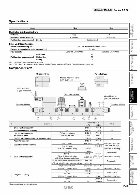
Specifications
Model LLB3 LLB4
Stainless steelNeedle
0.28
8 rotations
1.4
10 rotations
Cv factor
Number of needle rotations
Fluid contact space material
Restrictor Unit Specifications
Filter case
Hollow fiber
Potting
0.01 µm (Filtration efficiency 99.99%)
0.5 MPa
PC
PP
PU
Up to 100 L/min (ANR) Up to 500 L/min (ANR)
Normal filtration rating Note 1)
Element withstand differential pressure Note 2)
Flow capacity
Fluid contact space material
Filter Unit Specifications
Note 1) According to SMC measurement conditions.Note 2) This means that the element will not break at 0.5 MPa. Refer to Installation of Specific Product Precautions prior to use.
Component Parts
Threaded type Threaded type
Manual operation valve(with lever lock)
With flow adjuster
Lead wire with L-type connector
With differentialpressure indicator
One-touch fittingOne-touch fitting
No. DescriptionIndividual part no.
LLB3 LLB4Note
1
2
3
4
5
6
7
Clean regulator assembly
Pressure outlet port assembly
ON/OFF valve assembly/Manual operation valve
Restrictor assembly
Digital flow switch assembly
Clean air filter assembly
End plate assembly
ON/OFF valve assembly/Air operated valve
—
—
Without flow adjuster
With flow adjuster
—
—
5 to 100 L/min
50 to 500 L/min
With ø10 One-touch fitting
Rc 1/4
NPT 1/4
Rc 1/4, with differential pressure indicator
NPT 1/4, with differential pressure indicator
Replacement element
With ø10 One-touch fitting
Rc 1/4
NPT 1/4
With ø12 One-touch fitting
Rc 3/8
NPT 3/8
With ø10 One-touch fitting,with differential pressure indicator
LVB3-1
LVB3-2
LVB2-3
LVB2-3-1
LVB2-3-2
LVB2-4
LVB3-6-
—
LVB3-7-2
LVB3-7-3
LVB3-7-4
LVB3-7-2-1
LVB3-7-3-1
LVB3-7-4-1
SFD-EL101
LVB3-8-2
LVB3-8-3
LVB3-8-4
—
—
—
LVB4-1
LVB4-2
LVB4-3
LVB4-3-1
LVB4-3-2
LVB4-4
—
LVB4-6-
LVB4-7
SFD-EL050
—
—
—
LVB4-8-1
LVB4-8-2
LVB4-8-3
—
—
—
—
—
—
With One-touch fitting
Threaded type
With One-touch fitting
Threaded type
—
With One-touch fitting
Threaded type
With One-touch fitting
Threaded type
∗ Each module has 2 connecting brackets.
With L-type connectorWith lead wire (3 m)
Filter bodyonly
1042
Air
Pre
par
atio
nE
qu
ipm
ent
Pre
ssur
e C
ontr
olE
quip
men
tF
low
Co
ntr
ol
Eq
uip
men
tPr
essu
re S
witc
hes/
Pres
sure
Sen
sors
Dir
ecti
on
alC
on
tro
l Val
ves
Air
Gri
pp
ers
Mo
du
lar
F. R
.Fi
ttin
gs &
Tub
ing
Air
Cyl
ind
ers
Rot
ary
Act
uato
rs
Flo
w r
ate
L/m
in (
AN
R)
Number of needle rotations
100
90
80
70
60
50
40
30
20
10
02 4 6 8 10
Set pressure0.4 MPa
0.3 MPa
0.2 MPa
0.1 MPa
Flo
w r
ate
L/m
in (
AN
R)
Fluid pressure (MPa)
120
100
80
60
40
20
00.1 0.2 0.3 0.4 0.5
Flo
w r
ate
L/m
in (
AN
R)
Fluid pressure (MPa)
Flo
w r
ate
L/m
in (
AN
R)
Number of needle rotations
500
400
300
200
100
01 2 3 4 5 6 7 8 9 1110
Set pressure0.4 MPa
0.3 MPa
0.1 MPa
0.2 MPa
PA
PB
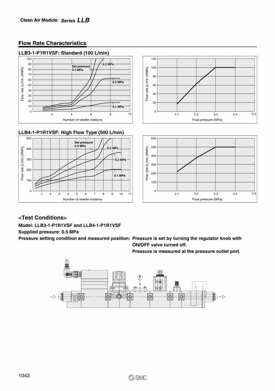
LLB3-1-P1R1VSF: Standard (100 L/min)
LLB4-1-P1R1VSF: High Flow Type (500 L/min)
<Test Conditions>Model: LLB3-1-P1R1VSF and LLB4-1-P1R1VSFSupplied pressure: 0.5 MPaPressure setting condition and measured position: Pressure is set by turning the regulator knob with ON/OFF valve turned off. Pressure is measured at the pressure outlet port.
Flow Rate Characteristics
600
500
400
300
200
100
00.1 0.2 0.3 0.4 0.5
Series LLBClean Air Module
1043
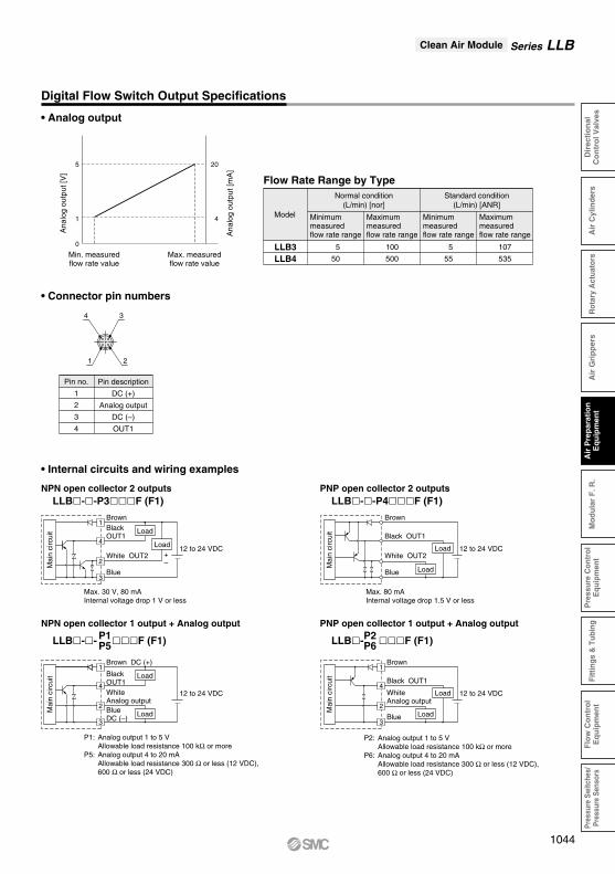
• Connector pin numbers
• Internal circuits and wiring examples
4 3
21
Max. measuredflow rate value
Min. measuredflow rate value
0
1
5
4
20
Ana
log
outp
ut [V
]
Ana
log
outp
ut [m
A]
Flow Rate Range by Type
5
50
100
500
5
55
107
535
LLB3LLB4
Model
Normal condition(L/min) [nor]
Minimum measuredflow rate range
Maximummeasuredflow rate range
Minimum measuredflow rate range
Maximummeasuredflow rate range
Standard condition(L/min) [ANR]
Pin no.
1
2
3
4
Pin description
DC (+)
Analog output
DC (–)
OUT1
Max. 30 V, 80 mAInternal voltage drop 1 V or less
NPN open collector 2 outputs LLB--P3F (F1)
PNP open collector 2 outputs LLB--P4F (F1)
Max. 80 mAInternal voltage drop 1.5 V or less
12 to 24 VDC
Brown
Black OUT1
White OUT2
Blue
Load
Load
NPN open collector 1 output + Analog output
LLB-- F (F1)
P1: Analog output 1 to 5 V Allowable load resistance 100 kΩ or moreP5: Analog output 4 to 20 mA Allowable load resistance 300 Ω or less (12 VDC), 600 Ω or less (24 VDC)
P2: Analog output 1 to 5 V Allowable load resistance 100 kΩ or moreP6: Analog output 4 to 20 mA Allowable load resistance 300 Ω or less (12 VDC), 600 Ω or less (24 VDC)
BrownBlackOUT1
White OUT2
Blue
12 to 24 VDC
Load
Load+–
1
4
2
3
Brown DC (+)
BlackOUT1
BlueDC (–)
12 to 24 VDCWhiteAnalog output
Load
Load
1
4
2
3
12 to 24 VDC
Brown
Black OUT1
WhiteAnalog output
Blue
Load
Load
1
4
2
3
P1P5
PNP open collector 1 output + Analog output
LLB- F (F1)P2P6
Mai
n ci
rcui
t
Mai
n ci
rcui
t
Mai
n ci
rcui
t
Mai
n ci
rcui
t
Digital Flow Switch Output Specifications
• Analog output
Series LLBClean Air Module
1044
Air
Pre
par
atio
nE
qu
ipm
ent
Pre
ssur
e C
ontr
olE
quip
men
tF
low
Co
ntr
ol
Eq
uip
men
tPr
essu
re S
witc
hes/
Pres
sure
Sen
sors
Dir
ecti
on
alC
on
tro
l Val
ves
Air
Gri
pp
ers
Mo
du
lar
F. R
.Fi
ttin
gs &
Tub
ing
Air
Cyl
ind
ers
Rot
ary
Act
uato
rs
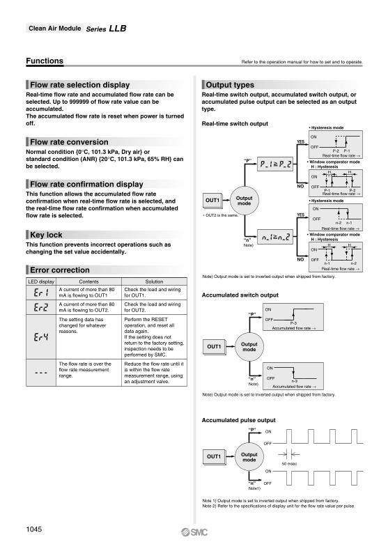
Refer to the operation manual for how to set and to operate.Functions
Flow rate selection display
Flow rate conversion
This function allows the accumulated flow rate confirmation when real-time flow rate is selected, and the real-time flow rate confirmation when accumulated flow rate is selected.
This function prevents incorrect operations such as changing the set value accidentally.
Real-time flow rate and accumulated flow rate can be selected. Up to 999999 of flow rate value can be accumulated.The accumulated flow rate is reset when power is turned off.
Normal condition 0°C, 101.3 kPa, Dry air orstandard condition (ANR) 20°C, 101.3 kPa, 65% RH can be selected.
Flow rate confirmation display
Key lock
Error correctionLED display Contents Solution
A current of more than 80 mA is flowing to OUT1
A current of more than 80 mA is flowing to OUT2.
The flow rate is over the flow rate measurement range.
The setting data has changed for whatever reasons.
Check the load and wiring for OUT1.
Check the load and wiring for OUT2.
Reduce the flow rate until it is within the flow rate measurement range, using an adjustment valve.
Perform the RESET operation, and reset all data again.If the setting does not return to the factory setting, inspection needs to be performed by SMC.
Note)
Real-time switch output
YES
NO
YES
NO
“P”
“n”
OUT1 Outputmode
• Window comparator mode H : Hysteresis
• Window comparator mode H : Hysteresis
• Hysteresis mode
• Hysteresis mode
ON
OFFP-1P-2
ON
OFFn-1n-2
ON
OFFP-1 P-2
H H
H HON
OFFn-2n-1
Real-time flow rate →
Real-time flow rate →
Real-time flow rate →
Real-time flow rate →
Output typesReal-time switch output, accumulated switch output, or accumulated pulse output can be selected as an output type.
∗ OUT2 is the same.
Note) Output mode is set to inverted output when shipped from factory.
Accumulated switch output
“P”
“n”
OUT1
ON
OFFP-3
ON
OFFn-3
Accumulated flow rate →
Accumulated flow rate →Note)
Accumulated pulse output
Outputmode
50 msec
ON
OFF
ON
OFF
Outputmode
“P”
“n”
OUT1
Note1)
Note) Output mode is set to inverted output when shipped from factory.
Note 1) Output mode is set to inverted output when shipped from factory.Note 2) Refer to the specifications of display unit for the flow rate value per pulse.
Series LLBClean Air Module
1045
LLB4-1-PRVSF
85
3.5
A
95°
A
V2
1010
72.1
1
5870
508
76
5.5 39
49.5
50
45
20.5
37
278.5
1.5 4
35
V2
90°
A
A
PA
PB
36.5
13.2
37.5
25
349
(47.5) 60 49 (77.5)254545
3
(36.5)
5959
528
3.5 (3.5)
103
13.2
34.8
(41)111597180.441
521
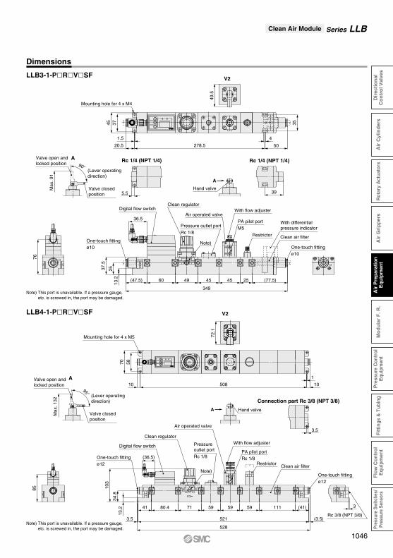
Dimensions
LLB3-1-PRVSF
Note) This port is unavailable. If a pressure gauge, etc. is screwed in, the port may be damaged.
Mounting hole for 4 x M4
Max
. 91
(Lever operatingdirection)
Valve open and locked position
Valve closed position
Hand valve
One-touch fittingø10
Clean air filter
With differentialpressure indicator
With flow adjuster
One-touch fittingø10
Clean regulator
Pressure outlet portRc 1/8 Restrictor
Note)
PA pilot portM5
Air operated valve
Rc 1/4 (NPT 1/4) Rc 1/4 (NPT 1/4)
Note) This port is unavailable. If a pressure gauge, etc. is screwed in, the port may be damaged.
Hand valve
(Lever operatingdirection)
Valve open and locked position
Valve closed position
Mounting hole for 4 x M5
Rc 3/8 (NPT 3/8)
Pressure outlet portRc 1/8One-touch fitting
ø12
One-touch fittingø12
Clean air filter
Digital flow switch
Digital flow switch
PA pilot portRc 1/8
Restrictor
With flow adjuster
Air operated valve
Clean regulator
Connection part Rc 3/8 (NPT 3/8)
Note)
Max
. 132
Series LLBClean Air Module
1046
Air
Pre
par
atio
nE
qu
ipm
ent
Pre
ssur
e C
ontr
olE
quip
men
tF
low
Co
ntr
ol
Eq
uip
men
tPr
essu
re S
witc
hes/
Pres
sure
Sen
sors
Dir
ecti
on
alC
on
tro
l Val
ves
Air
Gri
pp
ers
Mo
du
lar
F. R
.Fi
ttin
gs &
Tub
ing
Air
Cyl
ind
ers
Rot
ary
Act
uato
rs
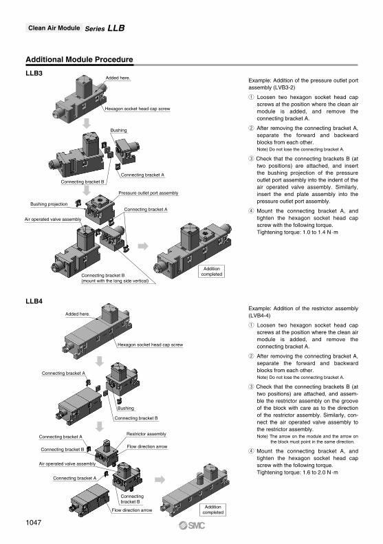
LLB4
Example: Addition of the pressure outlet port assembly (LVB3-2)
q Loosen two hexagon socket head cap screws at the position where the clean air module is added, and remove the connecting bracket A.
w After removing the connecting bracket A, separate the forward and backward blocks from each other.Note) Do not lose the connecting bracket A.
e Check that the connecting brackets B (at two positions) are attached, and insert the bushing projection of the pressure outlet port assembly into the indent of the air operated valve assembly. Similarly, insert the end plate assembly into the pressure outlet port assembly.
r Mount the connecting bracket A, and tighten the hexagon socket head cap screw with the following torque.Tightening torque: 1.0 to 1.4 N·m
Example: Addition of the restrictor assembly (LVB4-4)
q Loosen two hexagon socket head cap screws at the position where the clean air module is added, and remove the connecting bracket A.
w After removing the connecting bracket A, separate the forward and backward blocks from each other.Note) Do not lose the connecting bracket A.
e Check that the connecting brackets B (at two positions) are attached, and assem-ble the restrictor assembly on the groove of the block with care as to the direction of the restrictor assembly. Similarly, con-nect the air operated valve assembly to the restrictor assembly.Note) The arrow on the module and the arrow on
the block must point in the same direction.
r Mount the connecting bracket A, and tighten the hexagon socket head cap screw with the following torque.Tightening torque: 1.6 to 2.0 N·m
LLB3
Additional Module Procedure
Added here.
Hexagon socket head cap screw
Connecting bracket B
Connecting bracket A
Bushing
Pressure outlet port assembly
Connecting bracket ABushing projection
Air operated valve assembly
Connecting bracket B(mount with the long side vertical)
Additioncompleted
Added here.
Hexagon socket head cap screw
Bushing
Connecting bracket B
Connecting bracket A
Connecting bracket A
Connecting bracket B
Connecting bracket A
Connecting bracket B
Air operated valve assembly
Flow direction arrow
Restrictor assembly
Flow direction arrow
Additioncompleted
Series LLBClean Air Module
1047
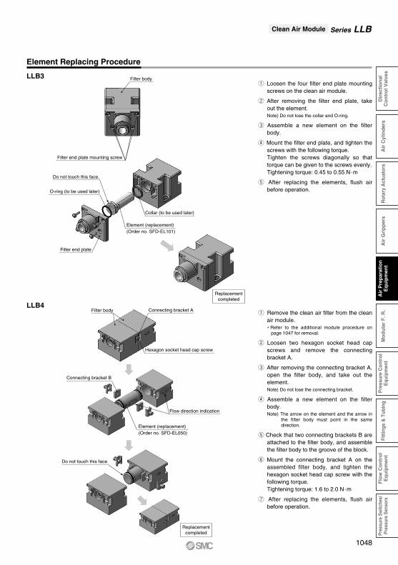
Filter body
Filter end plate mounting screw
Collar (to be used later)
Filter end plate
Element (replacement)(Order no. SFD-EL101)
O-ring (to be used later)
Do not touch this face.
Element Replacing Procedure
LLB3q Loosen the four filter end plate mounting
screws on the clean air module.
w After removing the filter end plate, take out the element.Note) Do not lose the collar and O-ring.
e Assemble a new element on the filter body.
r Mount the filter end plate, and tighten the screws with the following torque.Tighten the screws diagonally so that torque can be given to the screws evenly. Tightening torque: 0.45 to 0.55 N·m
t After replacing the elements, flush air before operation.
Replacementcompleted
Connecting bracket AFilter body
Hexagon socket head cap screw
Connecting bracket B
Flow direction indication
Element (replacement)(Order no. SFD-EL050)
Do not touch this face.
LLB4q Remove the clean air filter from the clean
air module.∗ Refer to the additional module procedure on
page 1047 for removal.
w Loosen two hexagon socket head cap screws and remove the connecting bracket A.
e After removing the connecting bracket A, open the filter body, and take out the element.Note) Do not lose the connecting bracket.
r Assemble a new element on the filter body.Note) The arrow on the element and the arrow in
the filter body must point in the same direction.
t Check that two connecting brackets B are attached to the filter body, and assemble the filter body to the groove of the block.
y Mount the connecting bracket A on the assembled filter body, and tighten the hexagon socket head cap screw with the following torque.Tightening torque: 1.6 to 2.0 N·m
u After replacing the elements, flush air before operation.
Replacementcompleted
Series LLBClean Air Module
1048
Air
Pre
par
atio
nE
qu
ipm
ent
Pre
ssur
e C
ontr
olE
quip
men
tF
low
Co
ntr
ol
Eq
uip
men
tPr
essu
re S
witc
hes/
Pres
sure
Sen
sors
Dir
ecti
on
alC
on
tro
l Val
ves
Air
Gri
pp
ers
Mo
du
lar
F. R
.Fi
ttin
gs &
Tub
ing
Air
Cyl
ind
ers
Rot
ary
Act
uato
rs

Series LLBClean Air Module / Precautions 1Be sure to read this before handling. Refer to page 1382 for Safety Instructions and pages 1064 to 1066 for Air Preparation Equipment Precautions.
Aftercooler
RefrigeratedAir Dryer
HeatlessAir Dryer
Super MistSeparatorAir TankAir Source
Main LineFilter
MistSeparator
Micro MistSeparator
OdorRemoval
Filter
Micro MistSeparator with
Prefilter
MembraneAir Dryer
LLB
123456
Qualityclass
0.1151540—
Maximumparticle size
(µm)
–70–40–203710
Minimumpressure dew point
(°C)
0.010.11.0525—
Maximumoil concentration
(mg/m3)
Design and Selection
Warning1. Confirm the specifications.
Give careful consideration to the operating conditions such as the application, fluid and environment, and use within the operating ranges specified in this catalog.
2. Ensure sufficient space for maintenance activities.Provide space required for maintenance.
3. Fluid pressure rangeSupplied fluid pressure must be within the operating pressure range specified in the catalog.
Mounting
Warning1. If air leakage increases or equipment does not oper-
ate properly, stop operation.After mounting is completed, confirm that it has been done correctly by performing a suitable function test and leakage test.
3. ISO compressed air quality classThe class regarding the cleanliness of compressed air (solid particles, moisture and oil) stipulated by ISO 8573-1:1991 (JIS B8392-1:2000)
Operating Environment
Warning1. Do not operate under the conditions listed below
due to a risk of malfunction.In locations having corrosive gases, organic solvents, and chemicals, or in locations in which these elements are likely to adhere to the equipment.In locations in which salt water, water, or water vapor could come in contact with the equipment.In locations that are exposed to direct sunlight. (Shield the equipment from sunlight to prevent its resin material from ultraviolet ray degradation or overheating.)In locations that have a heat source and poor ventilation. (Shield the equipment from heat sources to protect it from softening degradation due to radiated heat.)In locations that are exposed to shocks and vibrations.In locations with high humidity or a large amounts of dust.
2. When the product is used for blowing, use caution to prevent the workpiece from being damaged by entrained air from the surrounding area.When the compressed air is used for air blow, the exhausted air from the blow nozzle may have taken in airborne foreign matter (such as solid particle, fluid particle) from the surround-ing air. The foreign matter will be sprayed on the workpiece, and the airborne foreign matter may adhere to it. Therefore, use caution for the surrounding environment.
Recommended Pneumatic Circuit
Notation systemExample) Solid particle size: 0.1 µm Pressure dew point: 3°C Oil concentration: 0.1 mg/m3
With the above conditions, notation of the quality class is 1, 4, 2.
1049
Piping
Caution1. Preparation before piping
Before piping is connected, it should be thoroughly flushed out with air or washed to remove chips, cutting oil and other debris from inside the pipe.Install piping so that it does not apply pulling, pressing, bending or other forces on the module unit.
2. Be certain that sealing material does not enter the piping.When connecting pipes, fittings, etc., be sure that chips from the pipe threads and sealing material do not enter the module. Any dust or scale residing in the piping can cause malfunction or failure. Furthermore, when pipe tape is used, leave 1.5 to 2 thread ridges exposed at the end of the threads.
3. Use fittings with resin threads for the connection of fittings to the IN and OUT ports.Using fittings with metal threads could damage the ports.
4. Connect tubing to the IN and OUT One-touch fittings in accordance with the precautions for One-touch fittings.
Tightening Torque for Thread
LLB3LLB4
Size
2 to 38 to 9
Release torque(N·m)
0.5 to 12 to 3
Tightening torque(N·m)
2 to 3 rotations3 to 4 rotations
Tightening guide(Thread rotation number)
Other Tubing Brands
Caution1. When tubing of brands other than SMC’s are used,
verify that the tubing O.D. satisfies the following ac-curacy;1) Polyolefin tubing: Within ±0.1 mm2) Polyurethane tubing: Within +0.15 mm, within –0.2 mm3) Nylon tubing: Within ±0.1 mm4) Soft nylon tubing: Within ±0.1 mmDo not use tubing which does not meet these outside diame-ter tolerances. It may not be possible to connect them, or they may cause other trouble, such as air leakage or the tubing coming out after connection.The recommended tubing for the clean fitting is polyolefin tubing. Other tubing can satisfy the performance in terms of leakage, tensile strength, etc., but impair the cleanliness. Note this point for use.
Series LLBClean Air Module / Precautions 2Be sure to read this before handling. Refer to page 1382 for Safety Instructions and pages 1064 to 1066 for Air Preparation Equipment Precautions.
1050
Air
Pre
par
atio
nE
qu
ipm
ent
Pre
ssur
e C
ontr
olE
quip
men
tF
low
Co
ntr
ol
Eq
uip
men
tPr
essu
re S
witc
hes/
Pres
sure
Sen
sors
Dir
ecti
on
alC
on
tro
l Val
ves
Air
Gri
pp
ers
Mo
du
lar
F. R
.Fi
ttin
gs &
Tub
ing
Air
Cyl
ind
ers
Rot
ary
Act
uato
rs
Series LLBSpecific Product Precautions 1Be sure to read this before handling. Refer to page 1382 for Safety Instructions and pages 1064 to 1066 for Air Preparation Equipment Precautions.
Design and Selection
Warning1. Operate the switch only within the specified voltage.
Use of the switch outside the range of the specified voltage can cause not only malfunction and damage of the switch but also electrocution and fire.
2. Do not exceed the maximum allowable load specifi-cation.A load exceeding the maximum load specification can cause damage to the switch.
3. Do not use a load that generates surge voltage.Although surge protection is installed in the circuit at the out-put side of the switch, damage may still occur if a surge is ap-plied repeatedly. When a surge generating a load such as a relay or solenoid is directly driven, use a type of switch with a built-in surge absorbing element.
4. The switch does not have explosion proof struc-ture, so do not use flammable gas. Otherwise, fire may occur.
5. Monitor the internal voltage drop of the switch.When operating below a specified voltage, it is possible that the load may be ineffective even though the pressure switch function is normal. Therefore, the formula below should be satisfied after confirming the minimum operating voltage of the load.
6. Use the switch within the specified flow rate mea-surement and operating pressure.Operating beyond the specified flow rate and operating pressure can damage the switch.
Mounting
Warning4. Be sure to allow straight pipe length that is mini-
mum 8 times the port size for the inlet side of the switch piping.When abruptly reducing the size of piping or when there is a restriction such as a valve on the inlet side, the pressure dis-tribution in the piping changes and makes accurate measure-ment impossible.
Mounting
Warning1. Hold the body of the switch when handling.
The tensile strength of the lead wire with connector is 49N. Applying a greater pulling force on it can cause a malfunction. When handling, hold the body of the switch – do not dangle it from the wire.
2. Do not use until you can verify that equipment can operate properly.Following mounting, repair, or retrofit, conduct suitable function tests after piping and power connections have been made.
3. Never mount a switch in a place that will be used as a scaffold during piping.Damage may occur if an excessive load is applied to the switch.
Caution1. Data of the flow switch will be stored even after the
power is turned off.Input data will be stored in EEPROM so that the data will not be lost after the flow switch is turned off. (Data can be rewrit-ten for up to one million times, and data will be stored for up to 20 years.)
2. The accumulated flow rate is reset when power is turned off.
Operating Environment
Warning1. Never use in the presence of explosive gases.
The switches do not have an explosion proof rating. Never use in the presence of an explosive gas as this may cause a serious explosion.
2. Mount switches in locations where there is no vi-bration greater than 98 m/s2, or impact greater than 490 m/s2.
3. Do not use in an area where surges are generated.When there are units that generate a large amount of surge in the area around pressure switches, (e.g., solenoid type lifters, high frequency induction furnaces, motors, etc.) this may cause deterioration or damage to the switches' internal circuitry. Avoid sources of surge generation and crossed lines.
Wiring
Warning1. Verify the color and terminal number when wiring.
Incorrect wiring can cause the switch to be damaged and mal-function. Verify the color and the terminal number in the in-struction manual when wiring.
2. Avoid repeatedly bending or stretching the lead wire.Repeatedly applying bending stress or stretching force to the lead wire will cause it to break.
3. Confirm proper insulation of wiring.Make sure that there is no faulty wiring insulation (contact with other circuits, ground fault, improper insulation between termi-nals, etc.). Damage may occur due to excess current flow into a switch.
4. Do not wire in conjunction with power lines or high voltage lines.Wire separately from power lines and high voltage lines, avoiding wiring in the same conduit with these lines. Control circuits including switches may malfunction due to noise from these other lines.
5. Do not allow loads to short circuit.Although switches indicate excess current error if loads are short circuited, all incorrect wiring connections (power supply polarity, etc.) cannot be protected. Take precautions to avoid incorrect wiring.
Precautions on Digital Flow Switch
Supply
voltage
Internal voltage
drop of switchMinimum operating
voltage of load– >
1051
Operating Environment
Warning4. Switches are not equipped with surge protection
against lightning.Flow switches are CE compliant; however, they are not equipped with surge protection against lightning. Lightning surge protection measures should be applied directly to system components as necessary.
5. Avoid using switches in an environment where the likelihood of splashing or spraying of liquids exists.Switches are dustproof and splashproof; however, avoid using in an environment where the likelihood of heavy splashing or spraying of liquids exists.
6. Use the switch within the specified fluid and ambi-ent temperature range.The fluid temperature and ambient temperature ranges are 5 to 45°C, but the accuracy warranted range is 15 to 35°C. Take measures to prevent frozen fluid when using in low tempera-tures, since this may cause damage to the switch and lead to a malfunction. The installation of an air dryer is recommended to eliminate condensate and moisture. Never use the switch in an environment where there are drastic temperature changes even when these temperatures are within the specified tem-perature range.
Maintenance
Warning1. Perform periodical inspections to ensure proper op-
eration of the switch.Unexpected malfunctions may cause possible danger.
2. Take precautions when using the switch for an in-terlock circuit.When a pressure switch is used for an interlock circuit, devise a multiple interlock system to prevent trouble or malfunction-ing, verify the operation of the switch and interlock function on a regular basis.
3. Do not make any modifications to the product.
Measured Fluid
Warning1. The fluids that the switch can measure accurately
are nitrogen and clean air.Please note that accuracy cannot be guaranteed when other fluids are used.
2. Never use flammable fluids.The flow velocity sensor heats up to approximately 150°C.
Others
Warning1. Since switch output remains OFF while a message
is displayed after the power is turned on, start measurement after a value is displayed.
2. Perform settings after stopping control systems.When the switch's initial setting and flow rate setting are per-formed, output maintains the condition prior to the settings.
3. Do not apply excessive rotational force to the dis-play unit.The integrated type display unit can rotate 90°. If more rotation is required, a separate display unit is available as special order.
4. Be certain to turn on the power when the flow rate is at zero.Allow an interval of 10 minutes after turning on the power, as there are some changes in the display.
5. Flow rate unitSwitch measures at mass flow rates without being influenced by temperature and pressure. The switches use L/min as the flow rate indicator unit, in which the volumetric flow is substi-tuted for mass flow at 0°C and 101.3 kPa (NOR). The volu-metric flow rate at 20°C, 101.3 kPa, and 65%RH (ANR) can be displayed.
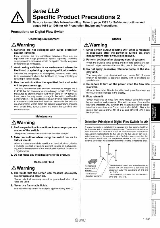
Detection Principle of Digital Flow Switch for AirA heated thermistor is installed in the passage, and fluid absorbs heat from the thermistor as it is introduced to the passage. The thermistor's resistance value increases as it loses heat. Since the resistance value increase ratio has a uniform relationship to the fluid velocity, the fluid velocity can be de-tected by measuring the resistance value. To further compensate the fluid and ambient temperature, the temperature sensor is also built into the switch to allow stable measurement within the operating temperature range.
Fluid velocitydetection element
Temperaturecompensation element
This flow switch uses L/min as the flow rate in-dicator unit. The mass flow is converted and displayed under the conditions of 0°C and 101.3 kPa.The conversion conditions can be switched to 20°C and 101.3 kPa.
Precautions on Digital Flow Switch
Series LLBSpecific Product Precautions 2Be sure to read this before handling. Refer to page 1382 for Safety Instructions and pages 1064 to 1066 for Air Preparation Equipment Precautions.
1052
Air
Pre
par
atio
nE
qu
ipm
ent
Pre
ssur
e C
ontr
olE
quip
men
tF
low
Co
ntr
ol
Eq
uip
men
tPr
essu
re S
witc
hes/
Pres
sure
Sen
sors
Dir
ecti
on
alC
on
tro
l Val
ves
Air
Gri
pp
ers
Mo
du
lar
F. R
.Fi
ttin
gs &
Tub
ing
Air
Cyl
ind
ers
Rot
ary
Act
uato
rs
Pressure Adjustment
Warning1. Do not use any tool to operate the pressure regula-
tor knob.Using a tool to operate the pressure regulator knob may cause breakage. Operate the knob by hand.
Caution1. Adjust pressure after unlocking the pressure regu-
lator knob.If the pressure regulator knob does not rotate, it is locked. Pull up on the pressure regulator knob once to unlock it. Rotating the knob forcibly may break the knob.After adjusting pressure, lock the knob. Press down on the knob to lock.
2. Adjust pressure by increasing the pressure.If pressure is adjusted by decreasing the pressure, pressure cannot be set correctly. Rotating the knob clockwise increases the outlet pressure, and rotating the knob counterclockwise decreases the pressure.
3. As this is a non-relief type regulator, rotating the knob counterclockwise does not decrease pres-sure.The non-relief type regulator does not decrease outlet pres-sure even if it is rotated counterclockwise unless the fluid at the outlet side is consumed.If the knob is rotated forcibly, the knob may break.If pressure setting is too high, consume fluid at the outlet side once to decrease the outlet pressure to the necessary set pressure or less, and set the pressure again.
4. Check the inlet pressure.The setting of the outlet pressure should be 85% or less of the inlet pressure. If the inlet pressure is low, pressure cannot be set correctly.
5. Do not operate fluid which contains solid matter.Otherwise, this may cause malfunction.
6. Oscillation (beat) may occur with some operating conditions even if the operation is within specifica-tion. Contact SMC for that case.
Precautions
Warning1. The maximum operating pressure and back pres-
sure must be within the specified range.
Caution1. Valve leakage
Valve leakage of 1 cm3/min or less (at pneumatic pressure) can happen when shipped from factory.
2. Product with flow adjuster can cause oscillation with some operating conditions if operating flow rate is very small, so examine the flow rate, pressure, and piping conditions carefully before operating.
3. For flow adjustment with flow adjuster, adjust the flow rate by opening the knob gradually from the fully closed state.Turning the adjusting knob counterclockwise opens the valve. Do not apply excessive force to the knob around the fully open or closed state. Otherwise, the orifice seat can be deformed or the adjusting knob screw can be broken. It is fully closed when shipped from factory.
4. Have a trial run before operation if the valve is not used for long periods of time.
5. Pay attention to the lever operating direction and handling of the lever.
Piping
Caution1. Tighten with the tightening torque below for pilot port.
2. Use the pilot ports and sensor (respiration) port as follows.
For N.C. and N.O. type, the port which is not pressurized should be open to atmosphere. If air intake to and exhaust from the valve is not preferable due to ambient atmosphere or dust, install piping to the valve so that the valve can intake/ exhaust air at the proper place.
Air Supply for Operation
Warning1. Use clean air.
If the compressed air is contaminated with chemicals, synthetic oil including organic solvent, salt, corrosive gas, etc., it may lead to the breakdown or malfunction of the equipment.
Precautions on Regulator Precautions on ON/OFF Valve
Tightening Torque for Operating PortOperating port
M5
Rc, NPT 1/8
Torque (N·m)After tightening by hand, tighten additional 1/6 rotation
with a tightening tool.
0.8 to 1.0
N.C.N.O.
Double acting
Sensor (respiration) portRespirationRespirationRespiration
PB portRespiration
PressurizationPressurization
PA portPressurization
RespirationPressurization
Series LLBSpecific Product Precautions 3Be sure to read this before handling. Refer to page 1382 for Safety Instructions and pages 1064 to 1066 for Air Preparation Equipment Precautions.
1053
Precautions
Warning1. Restrictor cannot be used as a stop valve, which
requires zero leakage. It is tolerant to some extent of leakage as a specification.
Maintenance
Warning1. When removing the product, exhaust the air and
ensure the air is released to atmosphere before re-moving it.
2. When the element comes to the end of its life, im-mediately replace it with a new filter or replacement element.Service life of element1) After 1 year of usage has elapsed.2) When the set flow rate is not achieved even if it has been
less than 1 year since operation started.
Operating Environment
Warning1. Do not operate under the conditions listed below
due to a risk of malfunction.• In locations having corrosive gases, organic solvents, and
chemicals, or in locations in which these elements are likely to adhere to the equipment.
• In locations in which salt water, water, or water vapor could come in contact with the equipment.
• In locations that are exposed to direct sunlight. (Shield the equipment from sunlight to prevent its resin material from ul-traviolet ray degradation or overheating.)
• In locations that have a heat source and poor ventilation. (Shield the equipment from heat sources to protect it from softening degradation due to radiated heat.)
• In locations that are exposed to shocks and vibrations.• In locations with high humidity or a large amounts of dust.
2. When the product is used for blowing, use caution to prevent the work from being damaged by entrained air from the surrounding area.When the compressed air is used for air blow, the exhausted air from the blow nozzle may have taken in airborne foreign matter (such as solid particle, fluid particle) from the surround air. The foreign matter will be sprayed on the work, and the airborne foreign matter may adhere to it. Therefore, use caution for the surrounding environment.
Installation
Warning1. Air equipment which is mounted on the outlet side
may generate dust.If air equipment is installed on the outlet side, the equipment may generate dust, and it will be a factor to deteriorate cleanli-ness. Examine the position to install air equipment.
2. Set operating flow rate within the specified range.[Specified range]LLB3: 100 L/min (ANR) or lessLLB4: 500 L/min (ANR) or lessIf the operating flow rate is out of the specified range, it will cause functional deterioration and breakage.
3. The filter should be installed in a place where pul-sation does not occur.
4. This product cannot operate compressed air which contains fluid such as water and oil.• For the air source for this product, install a dryer, mist
separator, micro mist separator, super mist separator, odor removal filter, etc.
• Generally, compressed air contains following particle contaminants:[Example of particle contaminants contained in compressed air]• Moisture (Condensate)• Dust in atmospheric air• Deteriorated oil exhausted from the compressor• Solid foreign matter such as rust or oil in the piping
5. Flush air into the piping for cleaning before install-ing the product. To decrease the affect of dust from a connection, also flush air into the piping before using the product for the first time and when replaced.
Precautions on Restrictor
Precautions on Filter
2. Check the number of rotations of the needle valve.It does not rotate further because it has a drop-out prevention mechanism. Check the number of needle rotations. Rotating the needle too much may cause damage.
Series LLBSpecific Product Precautions 4Be sure to read this before handling. Refer to page 1382 for Safety Instructions and pages 1064 to 1066 for Air Preparation Equipment Precautions.
1054
Air
Pre
par
atio
nE
qu
ipm
ent
Pre
ssur
e C
ontr
olE
quip
men
tF
low
Co
ntr
ol
Eq
uip
men
tPr
essu
re S
witc
hes/
Pres
sure
Sen
sors
Dir
ecti
on
alC
on
tro
l Val
ves
Air
Gri
pp
ers
Mo
du
lar
F. R
.Fi
ttin
gs &
Tub
ing
Air
Cyl
ind
ers
Rot
ary
Act
uato
rs