Series HINO 300 Series Body Mounting Manual€¦ · HINO 300 Series Body Mounting Manual KC-AA102...
245
HINO 300 Series Body Mounting Manual KC-AA102 COMMON to all Hino Truck series Series
Transcript of Series HINO 300 Series Body Mounting Manual€¦ · HINO 300 Series Body Mounting Manual KC-AA102...

HINO 300 SeriesBody Mounting Manual
KC-AA102
COMMON toall Hino Truck series
Series
No part of this manual may be reproduced or transmitted in any form without the express writ-ten permission of Hino Motors, Ltd.
© 2008, All rights reserved. Printed in Japan.
PRODUCT PLANNING DIVISION
3-1-1, HINO-DAI, HINO-SHI, TOKYO, 191-8660 JAPAN
Telephone : 042-586-5249
Facsimile : 042-586-5868
2008 - 09
KC-AA102
Purpose
This manual is provided to Body and Equipment Manufacturers, including inter-mediateand/or final stage manufacturers (hereinafter collectively referred to as Body andEquipment Manufacturers), to provide :
• Technical instructions for Hino truck chassis with cab for mounting of bodies and alter-ations of chassis.
• An aid to Body and Equipment Manufacturers for producing safe vehicles under theirown discretion and responsibility.
• Other general advice for installation, modification or alteration.
when Body and Equipment Manufacturers install any body or other equipment ordevice on Hino truck chassis with cab (hereinafter collectively referred to as HinoChassis), or modify or alter a Hino Chassis.
Important
This manual contains the instructions commonly applicable to all Hino truck models.Peculiar instructions as chassis layout drawings, chassis mass, precautions etc. foreach model, are given separately in the peculiar body mounting manuals for each vehicle model (hereinafter collectively referred to as the "Manual for eachmodel").Therefore, this manual should be used together with the Manual for each modelseries.(Details of construction of Hino's Body Mounting Manual are mentioned at thelast part of this chapter.)
• The Manuals for each model is available in this CD-R.• For more information on mounting bodies and equipment or on chassis modifications,
refer to the appropriate workshop manuals, parts catalogs, maintenance guides andowner's or driver's manual.
• The information in this manual is accurate to the best of Hino's Knowledge at the timeof going to press. Hino reserves the right to modify any and all information withoutnotice and without obligation.
• Should more detailed data or information be needed, please contact authorized Hinodistributor.
KC-AA102
ABOUT THIS MANUAL
Warning
• It is the responsibility of the Body and Equipment Manufacturers or the Modificationcompanies to make sure that the completed vehicle with body and equipment, or aftermodification, conforms to all applicable laws and regulations of the country in which thevehicle is to be used (e. g. regulations on lighting, tilt, overall size, axle load, externalnoise control etc.).
• This manual does not guarantee the safety of a Hino chassis which has been installed,modified, or altered by Body and Equipment Manufacturers.
• This manual does not affect that the ultimate responsibility for the manufacture andmounting of the body, installation, modification or alteration on a Hino Chassisdevolves upon the Body and Equipment Manufacturer.
• Each individual Body and Equipment Manufacturer has the sole responsibility for thedesign, functions, materials and work concerning the body and equipment.
• Hino Motors, Ltd. does not assume any liability whatsoever for any injury to persons ordamage to property caused as a result of the utilization of this manual.
• Parts number as described in each page will be changed without forward notice.Therefore, consult to Hino distributor or sales dealer with regard to the exact partsnumber.
• Drawings as described in each page show as example for your reference. Details ofparts to be install each vehicle, see the Body Mounting Manual for the respectivemodel series.
KC-AA102
ABOUT THIS MANUAL

1. GENERAL PRECAUTIONS
2. CHASSIS FRAME
3. ENGINE AND ENGINE COMPARTMENT
4. PROPELLER SHAFT
5. BRAKE & HYDRAULIC PIPING
6. FUEL TANK
7. ELECTRICAL SYSTEM
8. EXHAUST SYSTEM
9. BATTERY
10. SUSPENSION AND TIRE
11. SPARE TIRE CARRIER
12. BODY & EQUIPMENT MOUNTING
13. BODY & EQUIPMENT CONTROLS
14. PAINTING
KC-AA102
CONTENTS

GENERAL PRECAUTIONS
1. GENERAL PRECAUTIONS ・・・・・・・・・・・・・・・・・・・・・・・・ 2
2. MOUNTING PRECAUTIONS・・・・・・・・・・・・・・・・・・・・・・・・ 4
3. BODY DESIGN AND CONSTRUCTION ・・・・・・・・・・・・・・ 8
4. NEVER MODIFY SAFETY PARTS ・・・・・・・・・・・・・・・・・・24
5. CLEARANCES ・・・・・・・・・・・・・・・・・・・・・・・・・・・・・・・・・・・・28
6. FIRE SHIELD ・・・・・・・・・・・・・・・・・・・・・・・・・・・・・・・・・・・・38
7. ACCESSIBILITY FOR MAINTENANCE ・・・・・・・・・・・・・・39
8. APPROACH AND DEPARTURE ANGLES・・・・・・・・・・・・40
9. EXTERNAL NOISE CONTROL PARTS ・・・・・・・・・・・・・・41
10. AVOIDING DAMAGE TO CHASSIS・・・・・・・・・・・・・・・・・・42
11. LEAF ADDITIONS ・・・・・・・・・・・・・・・・・・・・・・・・・・・・・・・・42
12. SHIPMENT ・・・・・・・・・・・・・・・・・・・・・・・・・・・・・・・・・・・・・・42
13. TOWING VEHICLES ・・・・・・・・・・・・・・・・・・・・・・・・・・・・・・42
14. COMPLYING WITH LAWS AND REGULATIONS ・・・・・・42
15. PREPARATION OF OPERATION MANUAL AND/OR MAINTENANCE & INSPECTION・・・・・・・・・・43
16. ESTABLISHING AFTER-SALE SERVICE SYSTEM・・・・43
17. BODY MOUNTING FOR MODEL WITH SRS AIR BAG ・・・・・・・・・・・・・・・・・・・・・・・・・・・・・・・・・・44
18. HOW TO MOUNT AN ATTACHMENT ON THE CAB ROOF ・・・・・・・・・・・・・・・・・・・・・・・・・・・・・・・・・・・・48
KC-AA102
Chapter 1
This section describes general precautions that must be taken whenmounting a standard body or equipment or when making alterationsto the chassis.
Improper mounting of a body or equipment or improper alterationsmay cause unforeseen faults in the vehicle and lead to serious acci-dents.
If you intend to mount a body or equipment, or make alterations tothe chassis of a HINO vehicle, be sure to observe the precautionsdescribed in this section.
GENERAL PRECAUTIONS1
KC-AA102 1

1. GENERAL PRECAUTIONS
Before Mounting and Alterations
The base vehicle has been proved for laws and regulations, performance, and safety,becoming a well-rounded vehicle.Pay particular attention not to impair its functions by mounting and alterations.
Thoroughly review the mounting and alteration methods and the modification to be madeto the standard parts through alteration, and verify the result of the review to see if thereis no technical and safety problems.
Laws and regulations related to the mounting and alterations place the minimum restric-tions. In making alterations to vehicle, care should be taken to design and fabricate them in such a manner as to satisfyvarious related law and regulations with an ample allowance.
Be sure that the materials used for mounting or alterations sufficiently meet the legalrequirements, the performance and safety standards, and that the resulting vehicleshould be as light weight as possible.
No difference in weight between right and left wheels should occur due to the mountingor alterations.
The materials and parts involved in the mounting or alteration work should be designedand fabricated to facilitate the inspection and maintenance of chassis parts after they aremounted on the vehicles.
Forward field of view must not be restricted by mounting or alterations.
During Mounting and Alterations
Be sure that the work not to damage the chassis or impair its functions.
When removing and reinstalling chassis components, be sure to follow the proceduresdescribed in the Workshop Manual issued by Hino Parts and Service Division.
All mounting job should be conducted in a manner avoiding local concentration of theload on the chassis frame. In order to distribute the load over the frames, all the wheelsshould be located on the same plane without distorting the frame.
Never make any modification (welding, padding, machining, heating, etc.) to the component parts of the important safety parts (accelera-tor, steering, brake, suspension, etc.) .
GENERAL PRECAUTIONS1
KC-AA102 2

After Mounting and Alterations
Check to see whether the materials or parts used for such work are produced as designed and satisfy predetermined performance requirementsand functions, and also whether they contain no defects.
If the handling, maintenance, and service methods change due to mounting and alter-ations, prepare the Instruction Manual and attach it to the completed vehicle.
Prepare Instruction Manuals, Service Guides, and so on about the handling and mainte-nance, service of the rear body or equipment as well as the inspection interval and attachthem to the completed vehicle.
Pay every attention to the after-sales service system for the mounted body or equipmentand alteration parts. Workshop Manuals of Hino chassis are optionally available at your local Hino Distributoror Sales dealer.
GENERAL PRECAUTIONS1
KC-AA102 3

2. MOUNTING PRECAUTIONS
Requests to Body and Equipment Manufacturers
Pay extra attention to safety of products in the design, fabrication, andinspection phases.
Design ensuring safety All products must be proven for safety and equipped with safety devices as required.(Specifically, the parts that may come into contact with the human body must be providedwith this measure.)The “industry-standard levels and safety of other products” should also be taken intoaccount.
Fabrication conforming to drawingsQuality of the fabricated products should conform to the instructions given in the draw-ings. (Prevention of wrong parts, missing parts, and assembly defects.)
Final inspectionConduct final inspection for all products and prepare Inspection Records.
Storage and management of drawings, documents, and Inspection Records.Set up the rules for storing the drawings, documents, and inspection Records concerninga. to c. and make them understood.
Prepare substantial Instruction Manuals and WARNING labels
Instruction ManualDescribe the effects of improper handling and usage upon the customer body and vehi-cle to details as Precautions.
Warning LabelsDescribe safety notes on labels as briefly as possible and affix them at appropriate posi-tions.
Precautions to Follow when Studying and designing body and Equipment
When studying and designing the installation of body and equipment, note the following ;
Observe the safety regulations, inspection standards, and other standards concerningthe vehicle.
If there are self-imposed control rules set up by the Automobile Manufacturer’sAssociation, Vehicle Body Industrial Association, and so on, follow them.
Pay extra attention to vehicle safety and prevention of accidents.
Body and equipment must be as lightweight as possible and their weight must be distrib-uted evenly to the left and right wheels.
GENERAL PRECAUTIONS1
KC-AA102 4
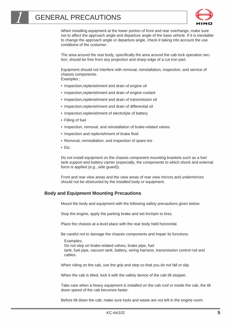
When installing equipment at the lower portion of front and rear overhangs, make surenot to affect the approach angle and departure angle of the base vehicle. If it is inevitableto change the approach angle or departure angle, check it taking into account the useconditions of the customer.
The area around the rear body, specifically the area around the cab lock operation sec-tion, should be free from any projection and sharp edge of a cut iron part.
Equipment should not interfere with removal, reinstallation, inspection, and service ofchassis components.Examples ;
• Inspection,replenishment and drain of engine oil
• Inspection,replenishment and drain of engine coolant
• Inspection,replenishment and drain of transmission oil
• Inspection,replenishment and drain of differential oil
• Inspection,replenishment of electrolyte of battery
• Filling of fuel
• Inspection, removal, and reinstallation of brake-related valves
• Inspection and replenishment of brake fluid
• Removal, reinstallation, and inspection of spare tire
• Etc.
Do not install equipment on the chassis component mounting brackets such as a fueltank support and battery carrier (especially, the components to which shock and externalforce is applied (e.g., side guard)).
Front and rear view areas and the view areas of rear view mirrors and undermirrorsshould not be obstructed by the installed body or equipment.
Body and Equipment Mounting Precautions
Mount the body and equipment with the following safety precautions given below.
Stop the engine, apply the parking brake and set linchpin to tires.
Place the chassis at a level place with the rear body held horizontal.
Be careful not to damage the chassis components and impair its functions.
Examples;Do not step on brake-related valves, brake pipe, fuel tank, fuel pipe, vacuum tank, battery, wiring harness, transmission control rod andcables.
When riding on the cab, use the grip and step so that you do not fall or slip.
When the cab is tilted, lock it with the safety device of the cab tilt stopper.
Take care when a heavy equipment is installed on the cab roof or inside the cab, the tiltdown speed of the cab becomes faster.
Before tilt down the cab, make sure tools and waste are not left in the engine room.
GENERAL PRECAUTIONS1
KC-AA102 5
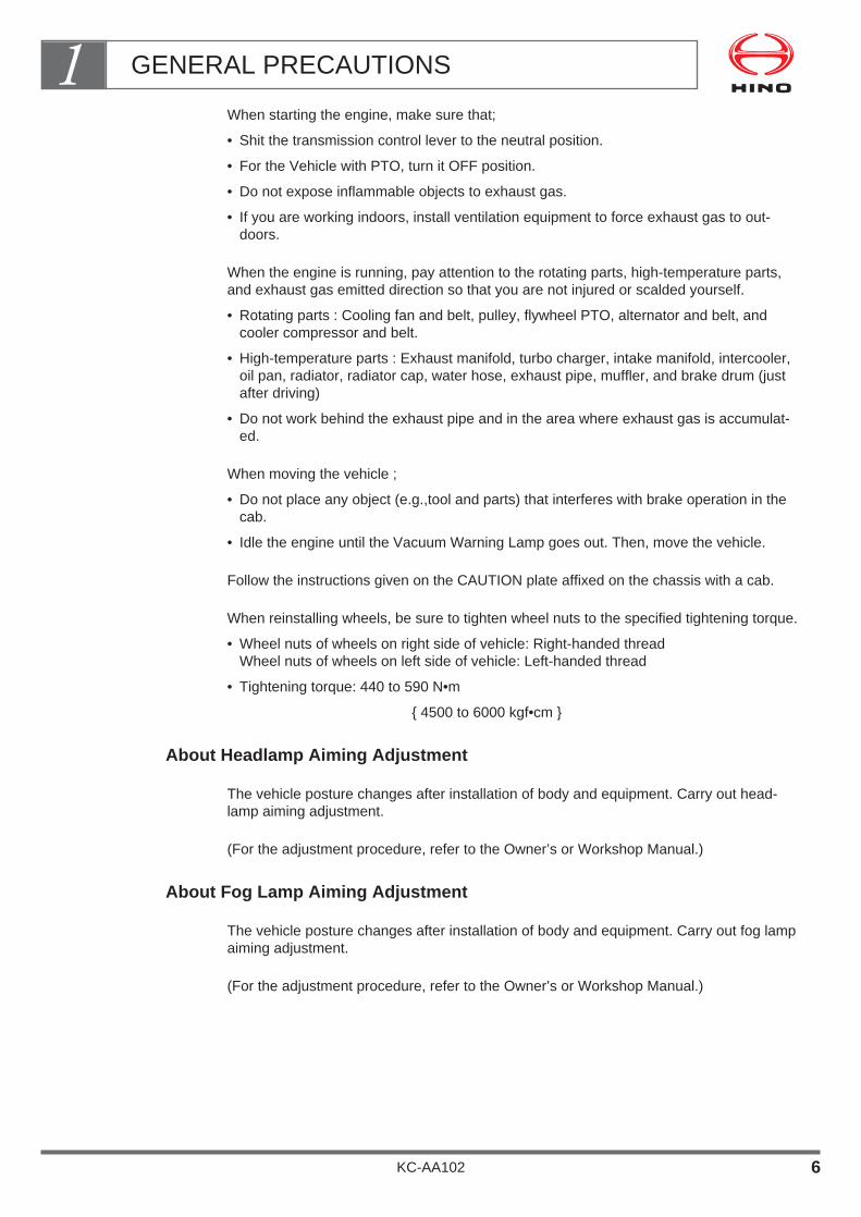
When starting the engine, make sure that;
• Shit the transmission control lever to the neutral position.
• For the Vehicle with PTO, turn it OFF position.
• Do not expose inflammable objects to exhaust gas.
• If you are working indoors, install ventilation equipment to force exhaust gas to out-doors.
When the engine is running, pay attention to the rotating parts, high-temperature parts,and exhaust gas emitted direction so that you are not injured or scalded yourself.
• Rotating parts : Cooling fan and belt, pulley, flywheel PTO, alternator and belt, andcooler compressor and belt.
• High-temperature parts : Exhaust manifold, turbo charger, intake manifold, intercooler,oil pan, radiator, radiator cap, water hose, exhaust pipe, muffler, and brake drum (justafter driving)
• Do not work behind the exhaust pipe and in the area where exhaust gas is accumulat-ed.
When moving the vehicle ;
• Do not place any object (e.g.,tool and parts) that interferes with brake operation in thecab.
• Idle the engine until the Vacuum Warning Lamp goes out. Then, move the vehicle.
Follow the instructions given on the CAUTION plate affixed on the chassis with a cab.
When reinstalling wheels, be sure to tighten wheel nuts to the specified tightening torque.
• Wheel nuts of wheels on right side of vehicle: Right-handed threadWheel nuts of wheels on left side of vehicle: Left-handed thread
• Tightening torque: 440 to 590 N•m
{ 4500 to 6000 kgf•cm }
About Headlamp Aiming Adjustment
The vehicle posture changes after installation of body and equipment. Carry out head-lamp aiming adjustment.
(For the adjustment procedure, refer to the Owner’s or Workshop Manual.)
About Fog Lamp Aiming Adjustment
The vehicle posture changes after installation of body and equipment. Carry out fog lampaiming adjustment.
(For the adjustment procedure, refer to the Owner’s or Workshop Manual.)
GENERAL PRECAUTIONS1
KC-AA102 6

About LSPV Adjustment
The vehicle posture and ground clearance change after installation of body and equip-ment. Adjust the LSPV.
(For the adjustment procedure, refer to the Owner’s or Workshop Manual.)
Precautions for Adjusting the Tire Air Pressure
When the chassis with cab is delivered, the tire air pressure is reduced to absorb theshocks and vibrations caused during transportation by road. After completion of mount-ing, adjust the tire air pressure.
(Adjust the tire air pressure properly according to the air pressure label affixed on thedoor pillar or Owner's or Workshop Manual.)
GENERAL PRECAUTIONS1
KC-AA102 7
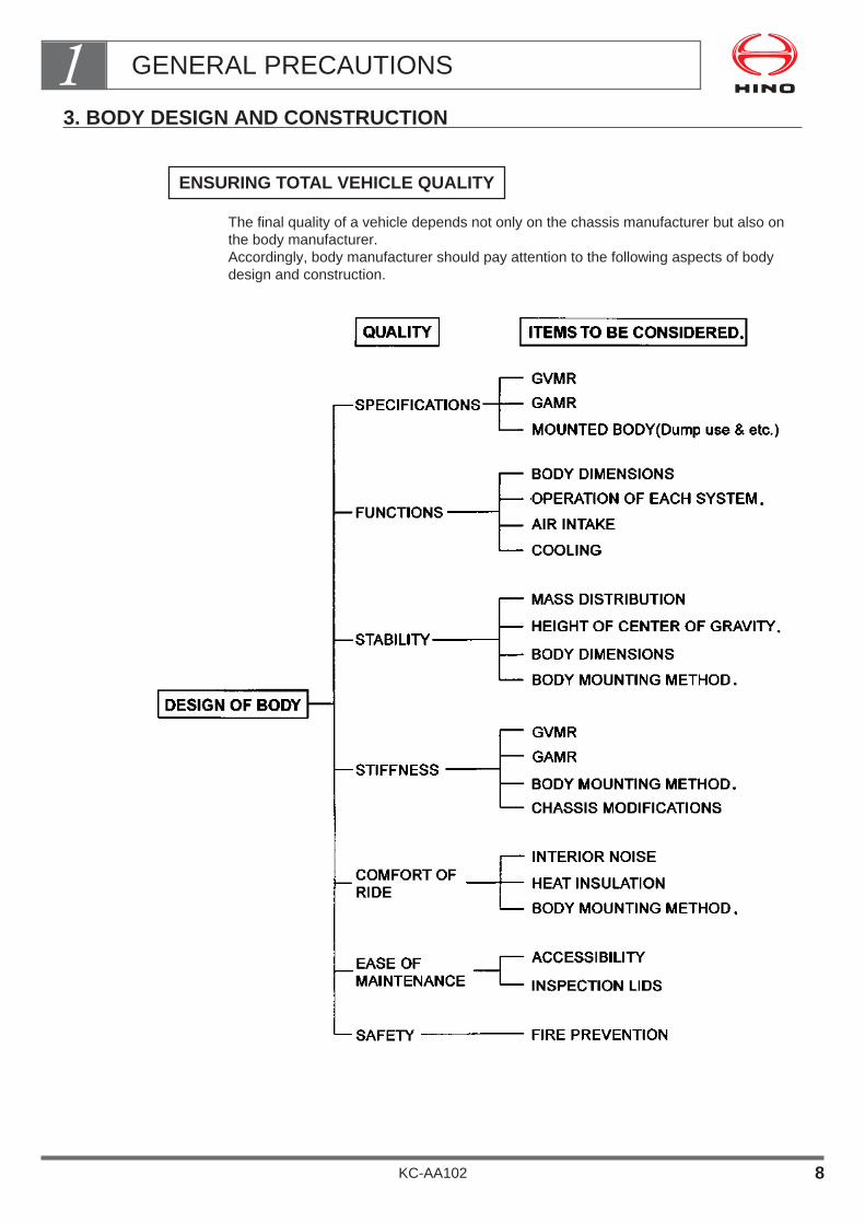
3. BODY DESIGN AND CONSTRUCTION
The final quality of a vehicle depends not only on the chassis manufacturer but also onthe body manufacturer.Accordingly, body manufacturer should pay attention to the following aspects of bodydesign and construction.
ENSURING TOTAL VEHICLE QUALITY
GENERAL PRECAUTIONS1
KC-AA102 8

Mass and Dimensions
When designing or constructing a body, make sure that;
the total mass of the vehicle is within the permissible axle capacity, tire capacity andgross vehicle mass (GVM).
the front axle load satisfies the minimum ratio of gross vehicle mass.
the height of the center of gravity from the ground after body mounting is within the speci-fied limit.
the vehicle mass is evenly distributed between left and right wheels.
the overall width of the vehicle is within the specified limit.
the dimensions and mass of the vehicle comply with local regulations.
The specified values for the above items are given under”1.Vehicle summary—ChassisSpecifications” in the Hino Body Mounting Manual for the respective model series.
For your reference, example of the chassis specifications to be given in the BodyMounting Manual for the respective model series is described in the next page.
GENERAL PRECAUTIONS1
KC-AA102 9
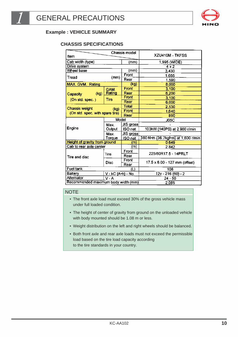
Example : VEHICLE SUMMARY
CHASSIS SPECIFICATIONS
NOTE• The front axle load must exceed 30% of the gross vehicle mass
under full loaded condition.
• The height of center of gravity from ground on the unloaded vehiclewith body mounted should be 1.08 m or less.
• Weight distribution on the left and right wheels should be balanced.
• Both front axle and rear axle loads must not exceed the permissibleload based on the tire load capacity according to the tire standards in your country.
GENERAL PRECAUTIONS1
KC-AA102 10
Formula for Calculation
When calculating
• gross vehicle mass
• body load center (offset), and
• height of center of gravity from ground for chassis with body mounted, use the formulaedescribed in this section.
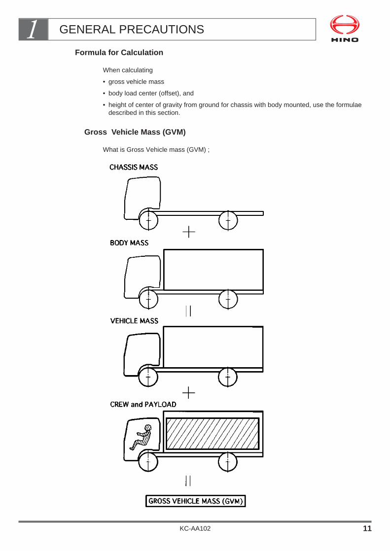
Gross Vehicle Mass (GVM)
What is Gross Vehicle mass (GVM) ;
GENERAL PRECAUTIONS1
KC-AA102 11
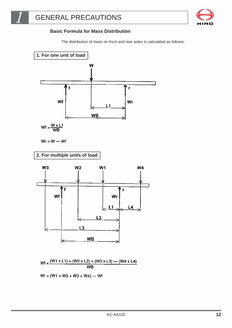
Basic Formula for Mass Distribution
The distribution of mass on front and rear axles is calculated as follows;
2. For multiple units of load
1. For one unit of load
GENERAL PRECAUTIONS1
KC-AA102 12
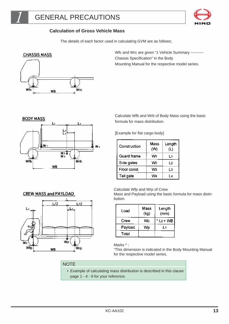
Calculation of Gross Vehicle Mass
The details of each factor used in calculating GVM are as follows;
Wfc and Wrc are given “1 Vehicle Summary ----------
Chassis Specification” in the Body
Mounting Manual for the respective model series.
Calculate Wfb and Wrb of Body Mass using the basic
formula for mass distribution.
[Example for flat cargo body]
Calculate Wfp and Wrp of Crew Mass and Payload using the basic formula for mass distri-bution.
Marks * :“This dimension is indicated in the Body Mounting Manualfor the respective model series.
NOTE• Example of calculating mass distribution is described in this clause
page 1 - 4 - 9 for your reference.
GENERAL PRECAUTIONS1
KC-AA102 13

Theoretical Calculation of Body Load Center (Load Offset)
a. Calculation of carrying capacity (CC)
CC = GVMR – (Chassis mass + Crews mass)= Body mass + Payload
For a Model XZU410M - TKFSS Cargo Truck(kg)
b. Calculation of carrying capacity load center
As carrying capacity load center is fixed, mountable body length can be calculated.L = 2,185 x 2 = 4,370 mm
Actual body offset is determined by the body length required by customer
and maximum permissible rear-overhang length.
GENERAL PRECAUTIONS1
KC-AA102 14

Mass Distribution on Front Axle (When loaded)
This means the percentage of vehicle total mass applied on front axle.
Front Axle Massx 100 ≥ 30%
Gross Vehicle Mass
The mass distribution on front axle has also a major impact on the steering and handlingof the vehicle.
Therefore on safety during running, make sure that the minimum 30% of vehicle totalmass applied on front axle.
Limit : Front axle mass Distribution ≥ 30%
GENERAL PRECAUTIONS1
KC-AA102 15
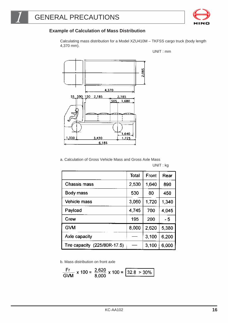
Example of Calculation of Mass Distribution
Calculating mass distribution for a Model XZU410M – TKFSS cargo truck (body length4,370 mm).
UNIT : mm
a. Calculation of Gross Vehicle Mass and Gross Axle Mass
UNIT : kg
b. Mass distribution on front axle
GENERAL PRECAUTIONS1
KC-AA102 16
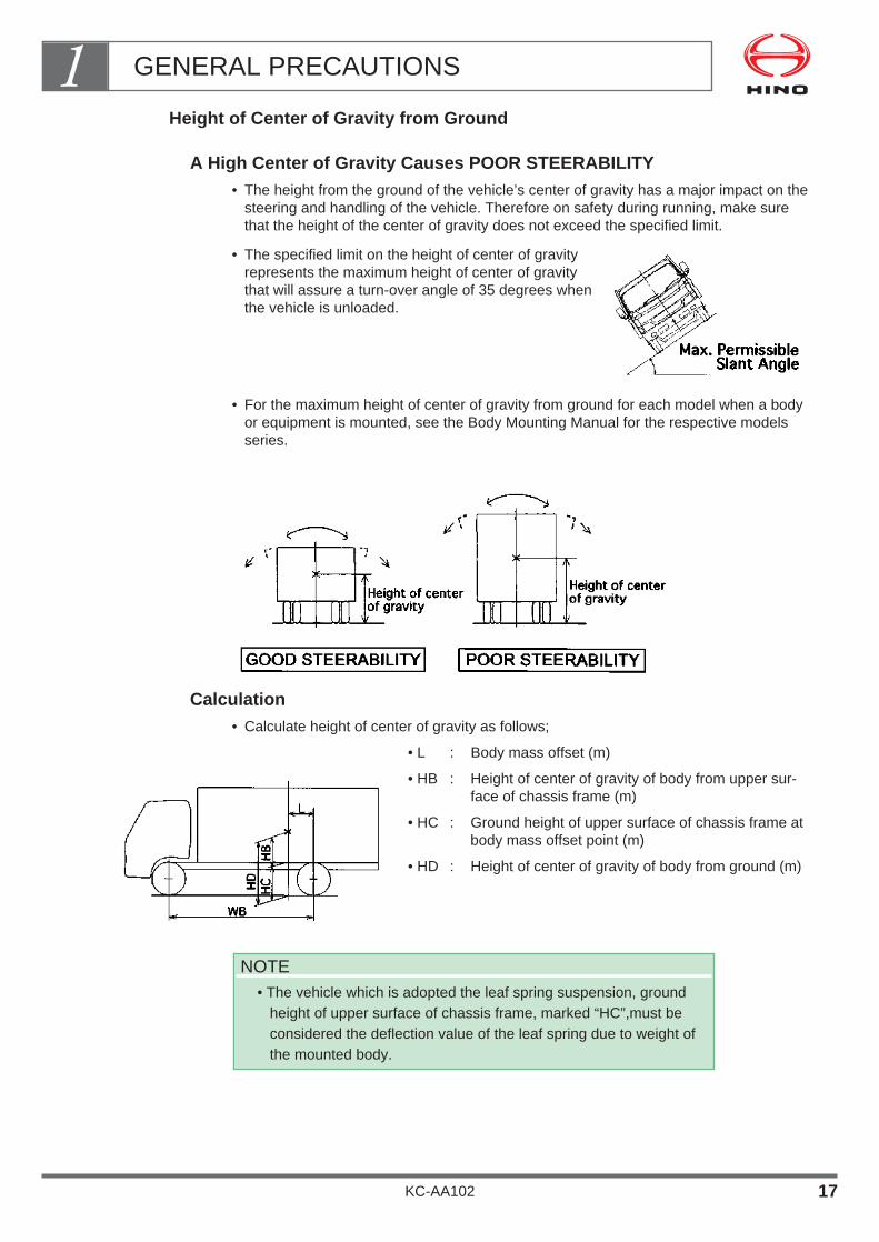
Height of Center of Gravity from Ground
A High Center of Gravity Causes POOR STEERABILITY• The height from the ground of the vehicle’s center of gravity has a major impact on the
steering and handling of the vehicle. Therefore on safety during running, make surethat the height of the center of gravity does not exceed the specified limit.
• The specified limit on the height of center of gravityrepresents the maximum height of center of gravitythat will assure a turn-over angle of 35 degrees whenthe vehicle is unloaded.
• For the maximum height of center of gravity from ground for each model when a bodyor equipment is mounted, see the Body Mounting Manual for the respective modelsseries.
Calculation• Calculate height of center of gravity as follows;
• L : Body mass offset (m)
• HB : Height of center of gravity of body from upper sur-face of chassis frame (m)
• HC : Ground height of upper surface of chassis frame atbody mass offset point (m)
• HD : Height of center of gravity of body from ground (m)
NOTE• The vehicle which is adopted the leaf spring suspension, ground
height of upper surface of chassis frame, marked “HC”,must beconsidered the deflection value of the leaf spring due to weight ofthe mounted body.
GENERAL PRECAUTIONS1
KC-AA102 17
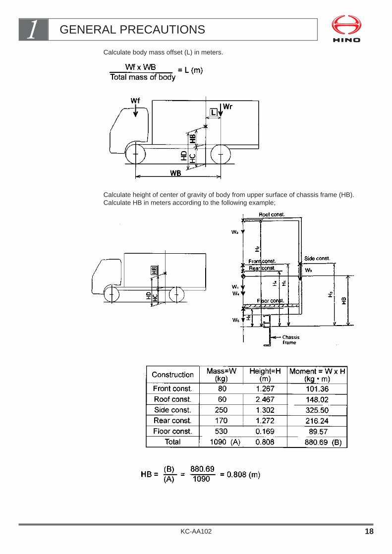
Calculate body mass offset (L) in meters.
Calculate height of center of gravity of body from upper surface of chassis frame (HB).Calculate HB in meters according to the following example;
GENERAL PRECAUTIONS1
KC-AA102 18

Calculate ground height of upper surface of chassis frame (HC) at body mass offset pointin meters.
Calculate height of center of gravity of body from ground (HD) in meters.
Finally, make sure that the height of the center of gravity of the vehicle does not exceedthe specified limit height of center of gravity from ground at the vehicle mass that isshown in the Body Mounting Manual for the respective model series.
If the height exceeds the specified limit, you must take steps to reduce the height andbring it within the limits specified in the Body Mounting Manual for the respective modelseries by modifying body design or other means.
HD (m) < limit specified in Body Mounting Manual for the
respective model series.
GENERAL PRECAUTIONS1
KC-AA102 19

Example
Height of center of gravity on model XZU410M-TKFSS truck with dry van body.
Dimensions marked "*" are indicated in the model series Body Mounting Manual.
HC = HR - {(HR-HF) x L/WB} HD = HB + HC
HC = 810 - {810 - 750) x 505/3,430} HD = 0.808 + 0.801
= 801 (mm) = 0.801 (m) = 1.609 (m)
This limit is specified in the Body
Mounting Manual for the respective
model series.
GENERAL PRECAUTIONS1
KC-AA102 20

Dimensions
It is the responsibility of the body and equipment manufacturer to ensure that the dimen-sions of the completed vehicle conform to the regulations of the country in which the vehicle is to be operated.When designing a body or equipment, in addition to observing the maximum height forthe center of gravity of the completed vehicle, you should also observe the maximumrear body or equipment width specified in the Body Mounting Manual for the respectivemodel series.Outline of vehicle's dimensions are described as follows;
GENERAL PRECAUTIONS1
KC-AA102 21
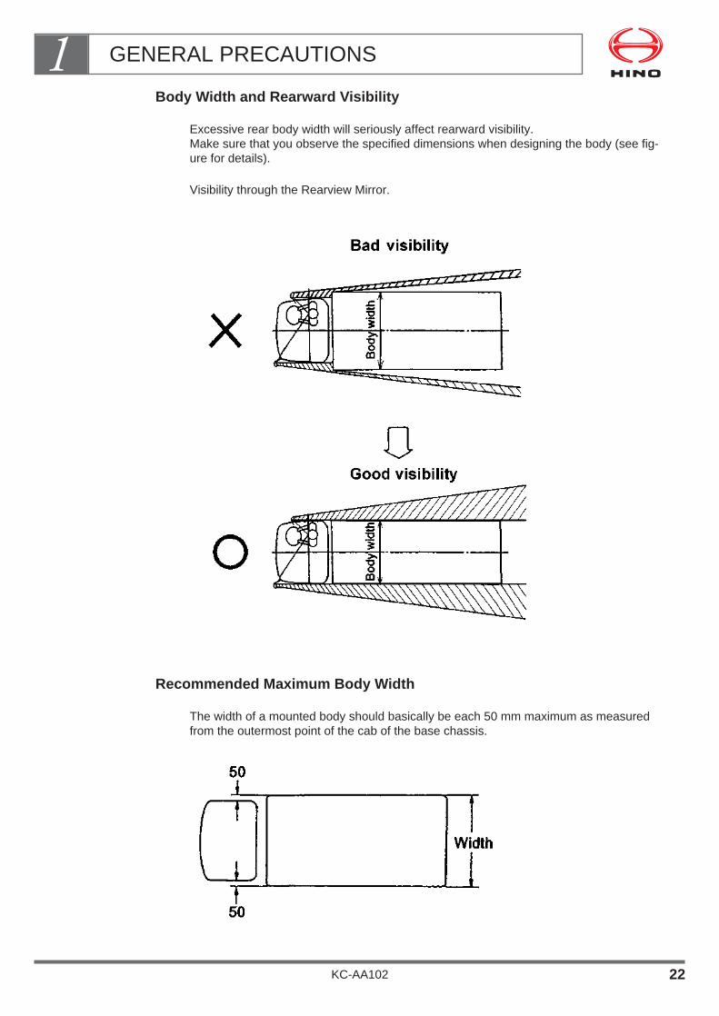
Body Width and Rearward Visibility
Excessive rear body width will seriously affect rearward visibility. Make sure that you observe the specified dimensions when designing the body (see fig-ure for details).
Visibility through the Rearview Mirror.
Recommended Maximum Body Width
The width of a mounted body should basically be each 50 mm maximum as measuredfrom the outermost point of the cab of the base chassis.
GENERAL PRECAUTIONS1
KC-AA102 22

When the difference in width between the cab and body is from 50 mm up to 100 mm onone side, provide chamfering of 45 degrees or less or a corner radius of 50 mm or moreat the front end of the rear body.
UNIT : mm
Rear Overhang
The rear overhang means the distance from the center of rear axle to the rear end of thevehicle and it is determined by wheelbase length.
Please see the limitation of its extension length below.
GENERAL PRECAUTIONS1
KC-AA102 23
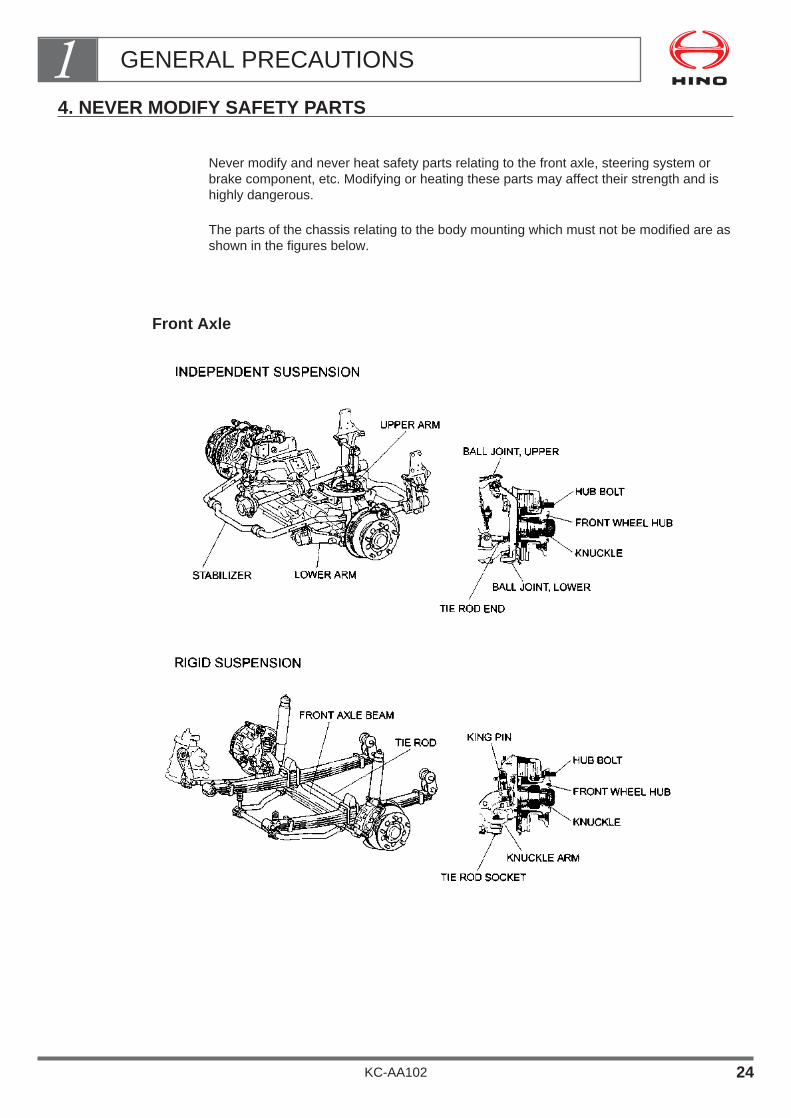
4. NEVER MODIFY SAFETY PARTS
Never modify and never heat safety parts relating to the front axle, steering system orbrake component, etc. Modifying or heating these parts may affect their strength and ishighly dangerous.
The parts of the chassis relating to the body mounting which must not be modified are asshown in the figures below.
Front Axle
GENERAL PRECAUTIONS1
KC-AA102 24
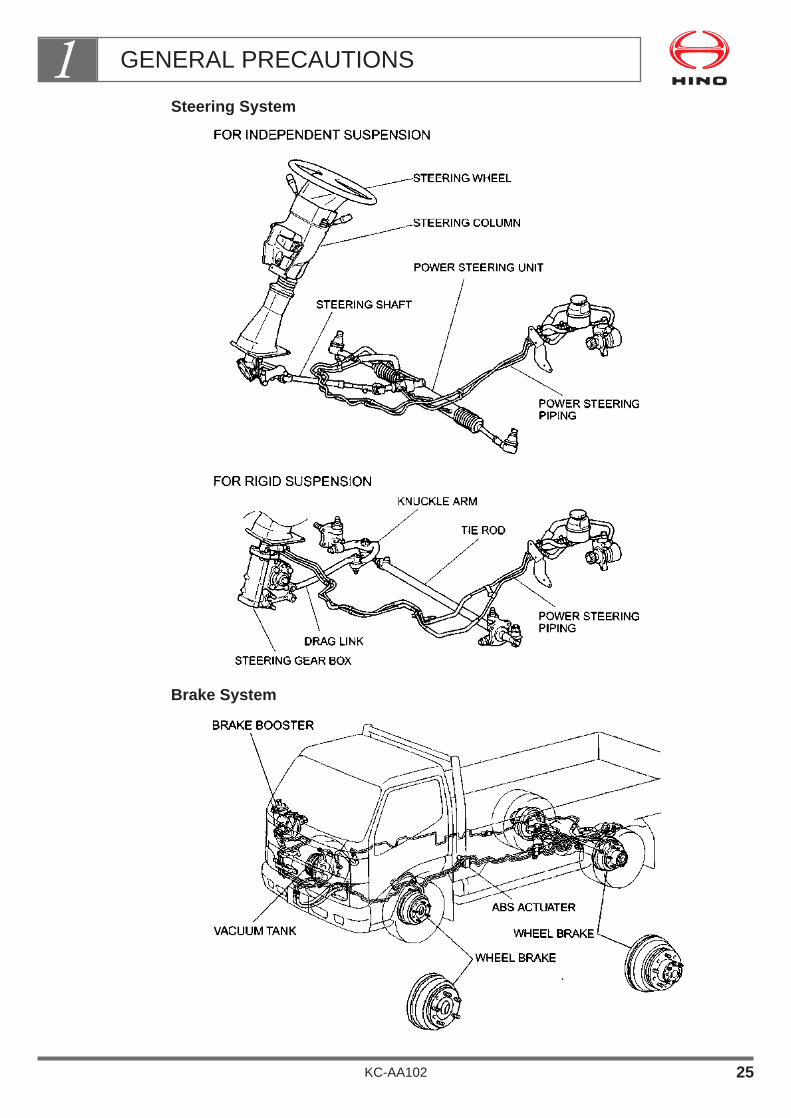
Steering System
Brake System
GENERAL PRECAUTIONS1
KC-AA102 25

Springs
FRONT
REAR
GENERAL PRECAUTIONS1
KC-AA102 26

Propeller Shaft
To alter the length of the wheel base it is necessary to modify the propeller shaft.However, improper modification of the propeller shaft may lead to damage and unusualnoises during driving or even cause serious accidents, and is therefore highly dangerous.
GENERAL PRECAUTIONS1
KC-AA102 27
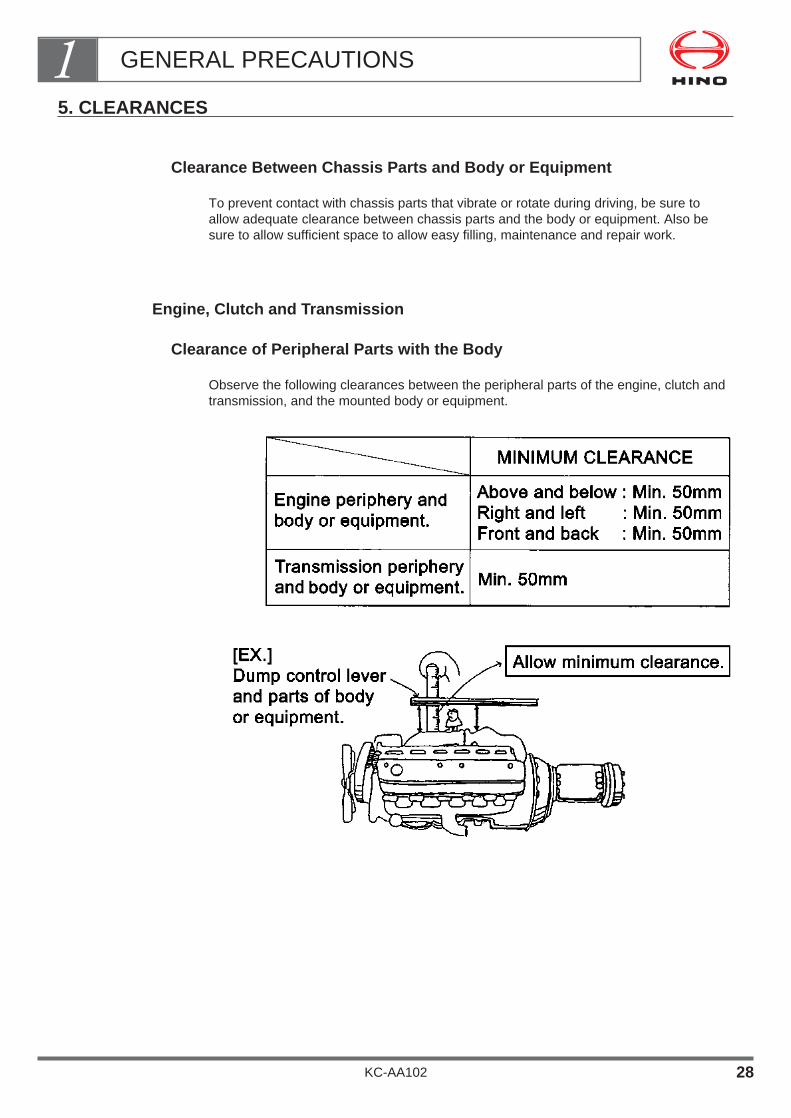
5. CLEARANCES
Clearance Between Chassis Parts and Body or Equipment
To prevent contact with chassis parts that vibrate or rotate during driving, be sure toallow adequate clearance between chassis parts and the body or equipment. Also besure to allow sufficient space to allow easy filling, maintenance and repair work.
Engine, Clutch and Transmission
Clearance of Peripheral Parts with the Body
Observe the following clearances between the peripheral parts of the engine, clutch andtransmission, and the mounted body or equipment.
GENERAL PRECAUTIONS1
KC-AA102 28

Space for Removal and Refitting of Transmission
When removing the clutch and transmission, to extract the clutch spline shaft, it is neces-sary to pull the transmission assembly backwards approximately 110 mm in the line ofthe engine. Make sure you allow enough space for this work.
Propeller Shaft
The clearance between the propeller shaft (including joints) and the body (pump bracketfor dump body, etc.) must be at least 50 mm from the limit of displacement of the pro-peller shaft (above, below, left, right, front or back of the axle).
GENERAL PRECAUTIONS1
KC-AA102 29
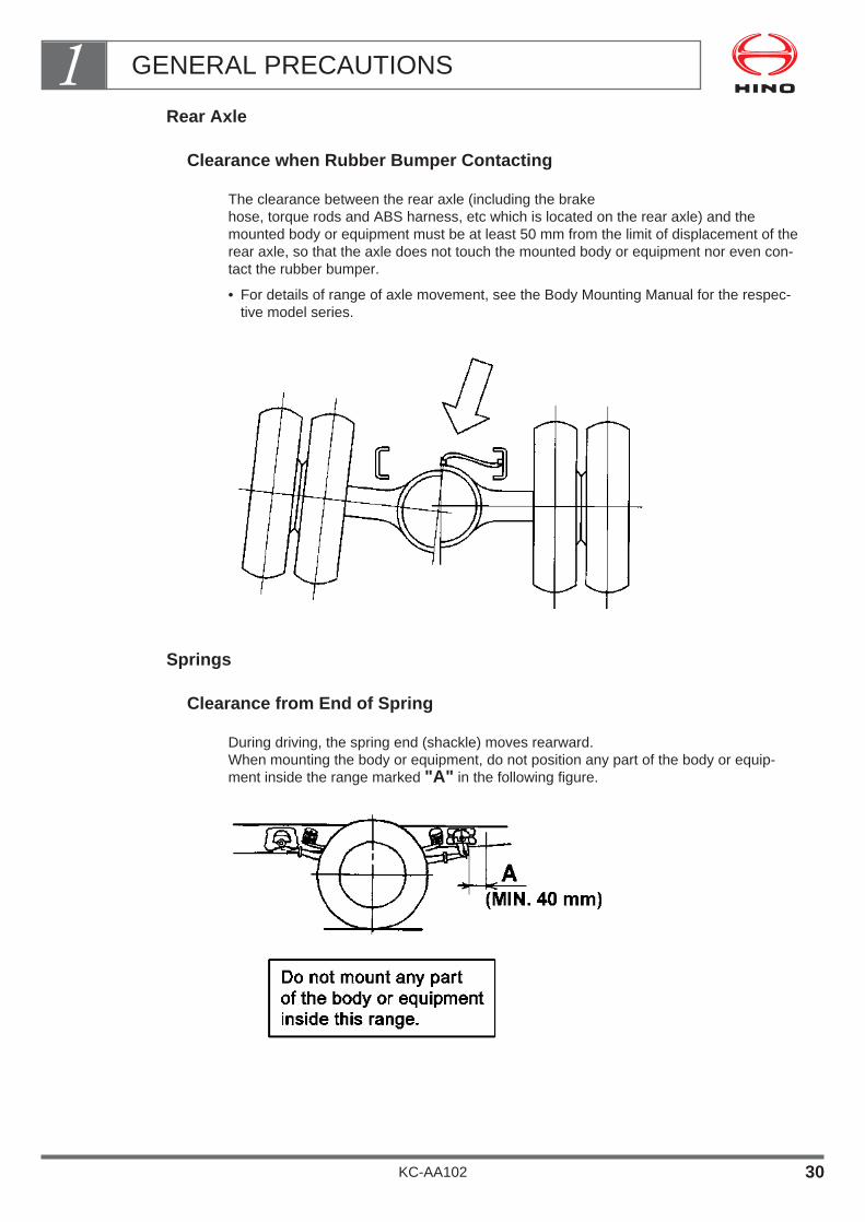
Rear Axle
Clearance when Rubber Bumper Contacting
The clearance between the rear axle (including the brake hose, torque rods and ABS harness, etc which is located on the rear axle) and themounted body or equipment must be at least 50 mm from the limit of displacement of therear axle, so that the axle does not touch the mounted body or equipment nor even con-tact the rubber bumper.
• For details of range of axle movement, see the Body Mounting Manual for the respec-tive model series.
Springs
Clearance from End of Spring
During driving, the spring end (shackle) moves rearward.When mounting the body or equipment, do not position any part of the body or equip-ment inside the range marked "A" in the following figure.
GENERAL PRECAUTIONS1
KC-AA102 30

Brake Hose and Pipe
Strictly observe the minimum clearances between the brake hose and pipe and the bodyor equipment. If the hoses are allowed to come into contact with the body or equipment,they will quickly become damaged and this may lead to serious accidents.
For details of minimum clearance, see clause 5. BRAKE & HYDRAULIC PIPING.
Electrical Wiring
Strictly observe the minimum clearances between electrical wiring and the body or equip-ment. If electrical wiring is allowed to come into contact with the body or equipment, it willquickly become damaged and this may lead to serious problems such as fire.
For details of minimum clearance, see clause 7. ELECTRICAL SYSTEM.
Exhaust muffler & Tail Pipe
Strictly observe the minimum clearances between the exhaust muffler or tail pipe and thebody or equipment. If the exhaust muffler or tail pipe are allowed to come into contactwith the body or equipment, this may lead to serious problems such as fire.
For details of minimum clearance, see clause 8. EXHAUST SYSTEM.
Fuel Tank Filler Cap
Space for Opening the Filler Cap and Filling
The fuel tank is mounted at the left or right side of the chassis. When mounting the bodyor equipment or making alterations, make sure that there is enough space to open thefiller cap and fill the tank with fuel.
GENERAL PRECAUTIONS1
KC-AA102 31
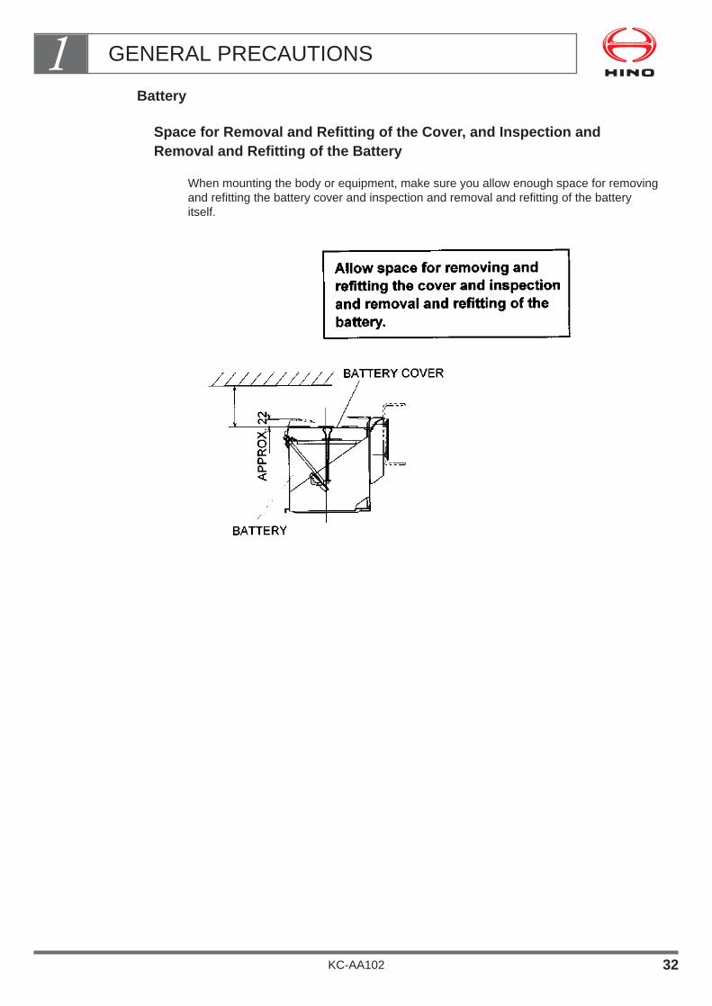
Battery
Space for Removal and Refitting of the Cover, and Inspection andRemoval and Refitting of the Battery
When mounting the body or equipment, make sure you allow enough space for removingand refitting the battery cover and inspection and removal and refitting of the batteryitself.
GENERAL PRECAUTIONS1
KC-AA102 32
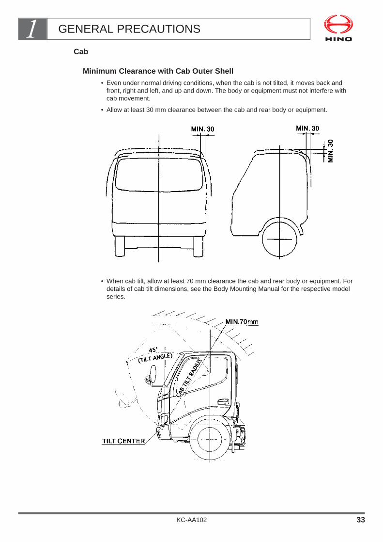
Cab
Minimum Clearance with Cab Outer Shell• Even under normal driving conditions, when the cab is not tilted, it moves back and
front, right and left, and up and down. The body or equipment must not interfere withcab movement.
• Allow at least 30 mm clearance between the cab and rear body or equipment.
• When cab tilt, allow at least 70 mm clearance the cab and rear body or equipment. Fordetails of cab tilt dimensions, see the Body Mounting Manual for the respective modelseries.
GENERAL PRECAUTIONS1
KC-AA102 33

Minimum Clearance with Cab Rear End
The rear part of the cab contains the cab lock mechanism and the tilt mechanism, as wellas the engine cylinder block or other various equipment.When mounting the body or equipment, allow at least the minimum clearance betweenthe rear end of the cab and the front end of the rear body or equipment, to avoidobstructing the operation and maintenance of these mechanisms or various equipment.
For details of cab dimensions, see the Body Mounting Manual for the respective modelseries.
GENERAL PRECAUTIONS1
KC-AA102 34
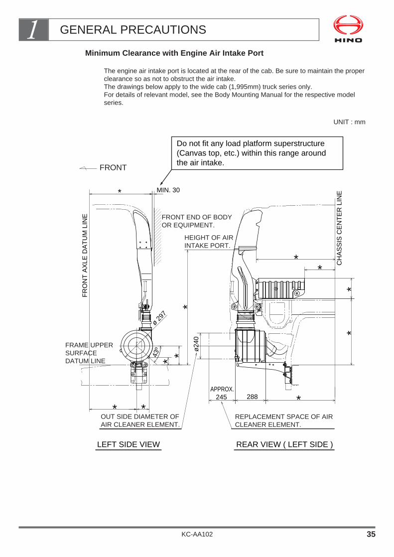
Minimum Clearance with Engine Air Intake Port
The engine air intake port is located at the rear of the cab. Be sure to maintain the properclearance so as not to obstruct the air intake.The drawings below apply to the wide cab (1,995mm) truck series only. For details of relevant model, see the Body Mounting Manual for the respective modelseries.
UNIT : mm
HEIGHT OF AIRINTAKE PORT.
FRONT END OF BODYOR EQUIPMENT.
FRAME UPPER SURFACEDATUM LINE
FR
ON
T A
XLE
DA
TU
M L
INE
CH
AS
SIS
CE
NT
ER
LIN
E
Do not fit any load platform superstructure(Canvas top, etc.) within this range aroundthe air intake.
MIN. 30*
**
*
*288APPROX. 245
**
43º
* *
OUT SIDE DIAMETER OF AIR CLEANER ELEMENT.
ø24
0
*
*
ø 297
REPLACEMENT SPACE OF AIR CLEANER ELEMENT.
FRONT
LEFT SIDE VIEW REAR VIEW ( LEFT SIDE )
GENERAL PRECAUTIONS1
KC-AA102 35
For details of dimensions marked " ", see the Body MountingManual for the respective model series.The blocking of the smooth flow of air into the air intake pipecaused by any materials such as ropes, pieces of cloth, etc. leadsto the increase of exhaust temperature if driven long intervals.The increase in exhaust temperature is caused by the decreasedefficiency in the combustion process, as the proportion of air in thecombustion chamber is also decreased by the above mentionedfactor.This situation will lead to major malfunctions such as the crackingof the exhaust manifold and the breaking down of the turbocharger.To avoid such malfunctions, please keep the air intake pipe freefrom any blocking materials at all times.
GENERAL PRECAUTIONS1
KC-AA102 36
*

Precautions of the Rear Hook and the Rear Body for Towing
Secure the clearance as indicated on the following illustration so that a sufficient spacecan be available for accommodating the towing rope.
GENERAL PRECAUTIONS1
KC-AA102 37

6. FIRE SHIELD
When a flat bed or similar body has been mounted, a fire shield should be fitted across the gap between the cab rear end and the front end of theload platform to prevent fires that may be caused by flammable materials falling off fromthe load platform onto the exhaust pipe (see figure below).A fire shield is not necessary if the body is fitted with a sheet carrier attached directly tothe top of the front guard.A fire shield is also not necessary for such bodies as dump trucks, mixers, tankers, andaluminum vans, where there is no danger of flammable materials falling off.
• For approximately 50mm from the front edge of fireshield (the cab side),use rubber to match the shape ofthe fire shield to that of the cab rear end such as reararch cover.
• You may also install the fire shield so that it covers onlythe exhaust pipe.
NOTE• When you mount the fire shield, use bolts, etc., that can be taken
out to allow for replacement of the chassis parts which are locatedat the rear part of cab.
GENERAL PRECAUTIONS1
KC-AA102 38
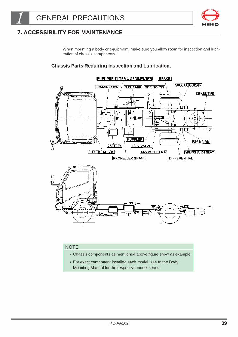
7. ACCESSIBILITY FOR MAINTENANCE
When mounting a body or equipment, make sure you allow room for inspection and lubri-cation of chassis components.
Chassis Parts Requiring Inspection and Lubrication.
NOTE• Chassis components as mentioned above figure show as example.
• For exact component installed each model, see to the BodyMounting Manual for the respective model series.
GENERAL PRECAUTIONS1
KC-AA102 39

8. APPROACH AND DEPARTURE ANGLES
If you intend to mount parts of the body or equipment at a relatively low position in thefront or rear overhang, make the approach angle and departure angle equal to or greaterthan the chassis standard angle.If, for unavoidable reasons, you must make these angles smaller than the chassis stan-dard, make sure to allow for operating conditions when deciding the ground height ofmounted parts of the body or equipment.
GENERAL PRECAUTIONS1
KC-AA102 40

9. EXTERNAL NOISE CONTROL PARTS
Precautions for Handling Parts
External noise control parts [sound-insulating materials (covers, rubber), sound-absorb-ing materials, a muffler and tail pipe] are fitted to meet regulations in the country in whichthe vehicle is to be used. When carrying out modifications, observe the following precau-tions:
• The specifications of each parts are determined in accordance with external noise con-trol regulations. Do not remove or alter the parts in any way.
• If you must temporarily detach any external noise control parts, handle it carefully inorder to avoid deforming or damaging it, and make sure you refit the parts in its originalposition when you have finished the body mounting or alteration work. If any externalnoise reduction parts is distorted or damaged, replace it with a new genuine part. Never usea repaired parts.
• For details of noise control parts, see the Body Mounting Manual for the respectivemodel series.
GENERAL PRECAUTIONS1
KC-AA102 41
10. AVOIDING DAMAGE TO CHASSIS
When mounting the body or equipment, be careful not to damage the chassis or interferewith its functions.For example, do not stand on brake component (ex. ABS modulator, LSPV), brake pipesand hoses, fuel pipes and hoses, battery and wiring harness, T/M control rods or cables,and etc.
11. LEAF ADDITIONS
Leaves should not be added to leaf springs beyond the number of leaves which have been prepared as an option as this may lead to snags inthe steering system at the front and unusual propeller shaft noise.
12. SHIPMENT
• After mounting the body or equipment, make sure that there is no body vibration, noiseor other abnormalities before shipping the vehicle. (Perform a thorough shippinginspection.)
• Brake, steering and suspension systems are all important safety components. If any ofthese components have had to be temporarily removed to allow for body mounting oralterations, make sure that they are refitted exactly as before and verify their operationbefore shipping the vehicle. (Be sure to perform a thorough shipping inspection.)
13. TOWING VEHICLES
If you must tow a vehicle, be sure to remove the propeller shaft before towing. (This isnot necessary when moving vehicles inside a factory during body mounting or alter-ations.)
14. COMPLYING WITH LAWS AND REGULATIONS
The completed vehicle with body or equipment fitted must comply with the vehicle lawsand regulations of the country in which it is used and tolerance limits for axle capacity,weight distribution on front axle and height of the center of gravity must not be exceeded.
GENERAL PRECAUTIONS1
KC-AA102 42

15. PREPARATION OF OPERATION MANUAL AND/OR MAINTENANCE &INSPECTION
Manual and Their Installation on Vehicles• In the event that the body mounting or modifications cause a change in the procedure
for operation, maintenance, inspection or adjustment of the standard vehicle, an opera-tion manual should be prepared and installed on the vehicle.
• An operation manual and/or a maintenance & inspection manual specifying the proce-dure for the operation, maintenance, inspection and adjustment including inspection intervals of the particularmounting or alterations should be prepared and installed in the vehicle.
16. ESTABLISHING AFTER-SALE SERVICE SYSTEM
Take adequate care to establish an after-sale service system for the parts mounted oraltered.
GENERAL PRECAUTIONS1
KC-AA102 43

17. BODY MOUNTING FOR MODEL WITH SRS AIR BAG
In case of the vehicle equipped a SRS air bag, be sure to take the following cautionssecurely.
Warning
• SRS stands for Supplemental Restraint System, a device to supplement the protectionof the crews.
Cautions for Alteration or Body Mounting
Do not make any reinforcement not modification at a part of cab floor.Otherwise, an impact to be conveyed to a sensor of SRS air bag will change, by whichSRS air bag will not function correctly.
Do not cover over the pad of steering wheel with something like a sticker, a cover, etc.At the same time, at an opening space for the air bag to be inflated, do not install anyattachment or do not place anything thereon.Otherwise, SRS air bag will not function correctly.
Do not make any modification of the suspension.A change of vehicle height or a change of the suspension hardness may lead to a mal-function of SRS air bag sensor.
An electric wave of wireless device may affect badly to the sensor of SRS air bag, bywhich SRS air bag functions.Take care to the following points for its installation.
Install an antenna, away possibly from SRS air bag sensor.
Install an antenna cord, 200 mm away from SRS air bag sensor.
Do not install a high power wireless device.
As the installation of the said device may affect to other electronic apparatus, install itsecurely in accordance with a "Installation Manual" by the manufacturer of the devices.
When body mounted, observe following cautioning points securely.
Otherwise, at the collision (accident), SRS air bag does not operate correct-
ly or inflates incorrectly, which may result in a serious injury.
GENERAL PRECAUTIONS1
KC-AA102 44
Cautions when Implementing an Alteration or Body Mounting
When implementing an alteration or body mounting for an electric attachments or cab,take off battery terminal ( - ) beforehand and start the work after more than 90 seconds.
When heating the cab (ex. welding, painting jobs) and its temperature exceeds85˚C,remove off SRS air bag and its sensor.Consult with your nearest Hino sales dealer or distributor when needed a dismountingwork.Also, take off a fuse of SRS air bag when implementing electric welding work to the cab.At the same time, to prevent damage from sparks during welding, cover with a heatresisting sheet the resin parts of SRS air bag and an instrument panel.
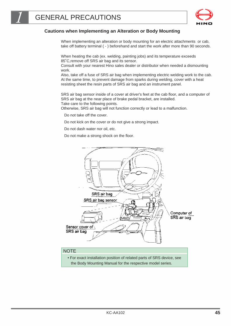
SRS air bag sensor inside of a cover at driver's feet at the cab floor, and a computer ofSRS air bag at the near place of brake pedal bracket, are installed.Take care to the following points.Otherwise, SRS air bag will not function correctly or lead to a malfunction.
Do not take off the cover.
Do not kick on the cover or do not give a strong impact.
Do not dash water nor oil, etc.
Do not make a strong shock on the floor.
NOTE• For exact installation position of related parts of SRS device, see
the Body Mounting Manual for the respective model series.
GENERAL PRECAUTIONS1
KC-AA102 45

Observe the following points when implementing a cab work.If not followed correctly, it may lead to not correct operation or malfunction of SRS airbag.
Do not take off nor damage the front floor reinforcement at driver's feet at cab floor.Also, do not insert such foreign materials as bolt, nut etc., between the front floor rein-forcement and the floor.
Do not take off nor damage a rubber mat underneath the floor mat at the cab floor.
SRS air bag is installed in at the pad of steering wheel.
Do not hit nor damage, nor give a strong shock to the SRS air bag.
Do not remove a stay installed in the steering post.
Do not touch electric wiring of SRS air bag.(The connectors of SRS air bag system are unified with yellow color.)Also, Never try to check the system by a general purpose tester, which may lead to amalfunction of SRS air bag.
Do not take out a power source of the mounting body or accessories from the fuse ofSRS air bag, which may lead to malfunction of SRS air bag.
SRS air bag and chassis numbers are recorded for manufacturer's control.When removed off the SRS air bag, install it to the original chassis without fail.
Check the warning lamp of SRS air bag after the alteration or body mounting work.
When there is not problem on the warning lamp and the engine switch is turned from"OFF" to "ON" or "ACC", the warning lamp is turned "on" and "off" after about 6 sec-onds.
When the warning lamp does not light up, even turning the engine switch to "ON" or"ACC", or remains light up, bring the vehicle to your nearest authorized Hino salesdealer or distributor for an inspection.
Observe the caution points specified in the workshop manual, when inspected at therepair shop.
Others
When SRS air bag inflates at accidents, etc., it can not be usable again. Change it atyour nearest Hino sales dealer or distributor.
When the vehicle or SRS air bag is scrapped, consult with your nearest Hino sales deal-er or distributor.
SRS air bag is a device to supplement a seat belt.But it can not function instead of the seat belt.Put on correctly the seat belt.You are requested to check it by driver's hand book, or to inquire it to your nearest autho-rized Hino sales dealer or distributor, regarding the detailed handling procedure.
GENERAL PRECAUTIONS1
KC-AA102 46
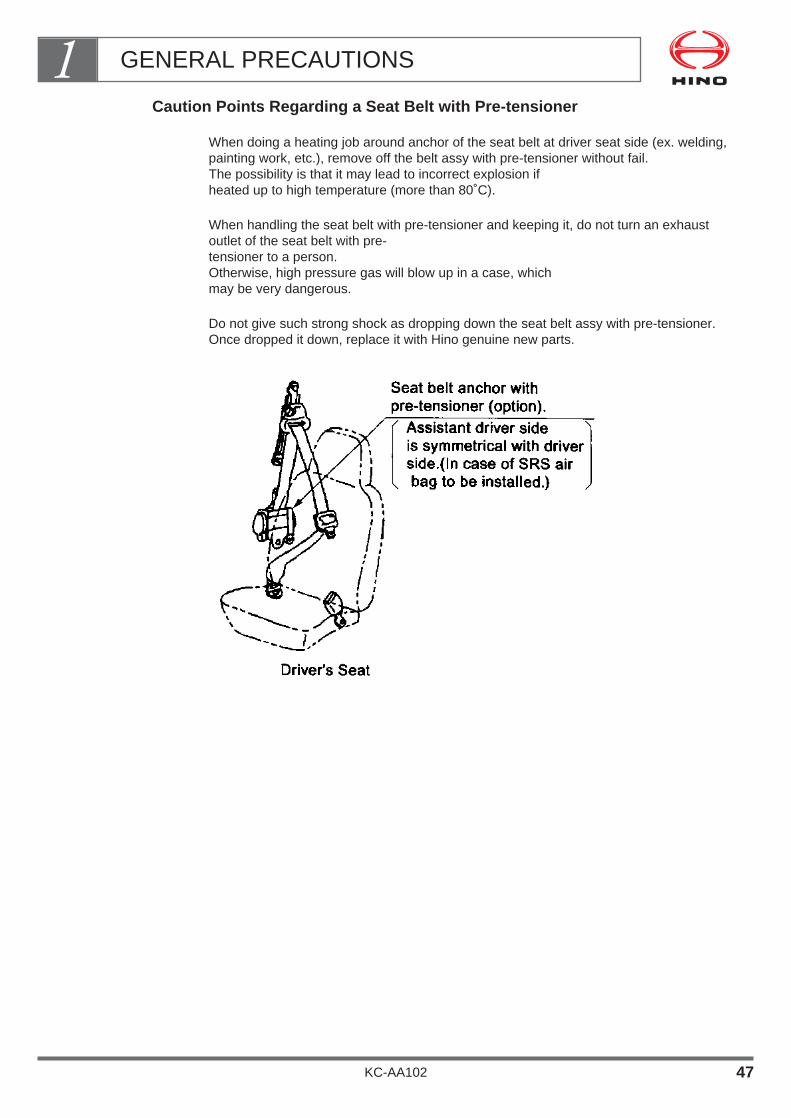
Caution Points Regarding a Seat Belt with Pre-tensioner
When doing a heating job around anchor of the seat belt at driver seat side (ex. welding,painting work, etc.), remove off the belt assy with pre-tensioner without fail.The possibility is that it may lead to incorrect explosion if heated up to high temperature (more than 80˚C).
When handling the seat belt with pre-tensioner and keeping it, do not turn an exhaustoutlet of the seat belt with pre-tensioner to a person.Otherwise, high pressure gas will blow up in a case, which may be very dangerous.
Do not give such strong shock as dropping down the seat belt assy with pre-tensioner.Once dropped it down, replace it with Hino genuine new parts.
GENERAL PRECAUTIONS1
KC-AA102 47

18. HOW TO MOUNT AN ATTACHMENT ON THE CAB ROOF
Bolt Hole Position for Mounting an Attachment
In order to facilitate mounting such attachments as roof rack,roof deflector etc. on the roof rails, nuts (M8 p.1.25) are provided in the figure below.
Cautions for Mounting Attachments on the Cab Roof
Observe the Following Points for Mounting Attachments
Blind bolts are inserted in the part of roof rails.Accordingly, take off those bolts when mounting the attachments on the cab roof. Do notuse those blind bolts for mounting the attachments.
The bolts and washers for mounting the attachments must be of nickel chrome stainlesstype. Chrome type stainless may get rusty possibly. Bolt size and tightening torque :
M8, 30 ± 6N•m (300 ± 60kgf•cm)
Mount the attachment on the cab roof, after painting completely.
Be careful not to scratch the painting while mounting.
GENERAL PRECAUTIONS1
KC-AA102 48

Insert rubber packing securely between the attachments and the roof (Refer to the fol-lowing figure) so as to avoid any scratch on the painted part of cab roof, not to get rustyand for water proof of the cab. The packing should be corresponding to RC710P (EPDM)or equivalent, and the thickness be less than 2 mm and the diameter of hole be 8 mm.
After tightening the installing bolt, apply silicon type sealer (corresponding to Three bondNo. 1211 or 1212) around the tightened bolt securely in order to avoid any water leak.
NOTE• When you install such attachment as roof rack, roof deflector etc.
on the cab roof, must be contacted with Hino sales dealer or distrib-utor to get more detail instruction as maximum load and etc.
GENERAL PRECAUTIONS1
KC-AA102 49

Shape of Window Deflector (for example)
GENERAL PRECAUTIONS1
KC-AA102 50

CHASSIS FRAME
1. FRAME MATERIALS ・・・・・・・・・・・・・・・・・・・・・・・・・・・・・・ 2
2. DRILLING AND WELDING ・・・・・・・・・・・・・・・・・・・・・・・・ 3
3. PROCESSING FOR DRILLING AND WELDING WORK ・・・・・・・・・・・・・・・・・・・・・・・・・・・・・・・・・・・・・・・・ 5
4. SIDE MEMBER REINFORCEMENT・・・・・・・・・・・・・・・・・・13
5. OTHER PRECAUTIONS FOR DRILLING AND ELECTRICAL WELDING ・・・・・・・・・・・・・・・・・・・・・・・・20
6. EXTENSION OF SIDE MEMBER REAR END ・・・・・・・・22
7. MOUNTING A PART ON THE SIDE MEMBER ・・・・・・・・23
KC-AA102
Chapter 2
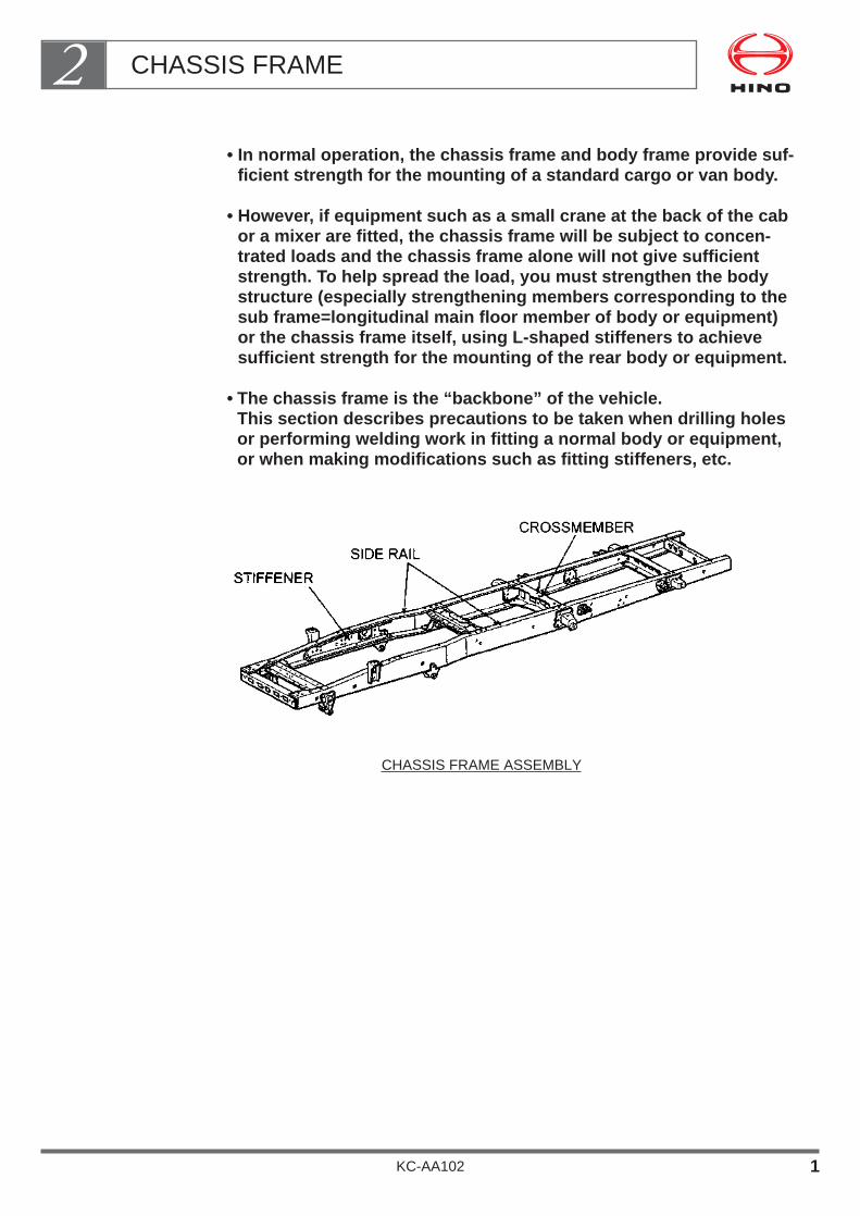
• In normal operation, the chassis frame and body frame provide suf-ficient strength for the mounting of a standard cargo or van body.
• However, if equipment such as a small crane at the back of the cabor a mixer are fitted, the chassis frame will be subject to concen-trated loads and the chassis frame alone will not give sufficientstrength. To help spread the load, you must strengthen the bodystructure (especially strengthening members corresponding to thesub frame=longitudinal main floor member of body or equipment)or the chassis frame itself, using L-shaped stiffeners to achievesufficient strength for the mounting of the rear body or equipment.
• The chassis frame is the “backbone” of the vehicle.This section describes precautions to be taken when drilling holesor performing welding work in fitting a normal body or equipment,or when making modifications such as fitting stiffeners, etc.
CHASSIS FRAME ASSEMBLY
CHASSIS FRAME2
KC-AA102 1

1. FRAME MATERIALS
HINO truck series use the following frame materials;
NOTE• Depending on the country in which the vehicle is to be used or type
of the vehicle, some models may use different frame material oftensile strength as mentioned in above table.
For details, see the Body Mounting Manual for the respectivemodel series.
CHASSIS FRAME2
KC-AA102 2

2. DRILLING AND WELDING
Summary of Drilling and Welding
Drilling and Welding of the frame may bring a great influence on the frame strength.Since Improper drilling and welding may result in the frame damage, avoid frame work ifat all possible. If unavoidable, make sure that there is no problem on the frame afterwork.
For your reference, please refer to the following basic precautions.
General informations
[Welding]
Tighten with bolts or rivets instead of welding. If this cannot bedone, the following precautions should be taken.
• Take off the chassis-mounted parts (brake lines, fuel lines and electricalcircuitry etc.) to protect them from sparks before performing welding.
• Clean the welded area before welding and make certain that the weldingrod is the one best suited for the materials to be welded.
• Keep welding speed and rod position in the optimum condition with thewelding current at the optimum amperage in order to avoid defective weld-ing work such as incomplete welding, undercut, slug fusing blowholes,cracks, pitting, etc.
• Always connect the ground wire close to the side rail area to be weldedand when welding, must be remove the battery terminals.
• To reduce stress caused by welding, minimize the length of the weldedarea as well as the amount of welding application.
• Avoid closespacing of weld joints as much as possible.
• Avoid welding edges and bends because high welding skill is required
[Drilling]
• Use an ordinary drill and never use heat such as a gas torch.
• Always chamfer after drilling.
CHASSIS FRAME2
KC-AA102 3

Side rail
CHASSIS FRAME2
KC-AA102 4

3. PROCESSING FOR DRILLING AND WELDING WORK
Use bolts or rivets for fastening and avoid welding as far as practicable.
Drilling
Don’t use gas or heat to form a hole but always use a drilling machine.
• After drilling, always finish with chamfering.
Drilling side memberDon’t drill in the upper and lower surface of the flange.
Make sure that the hole drilled is 11mm maximum.
When drilling a hole in the web surface, secure a distance of 100mm minimum from thespring bracket
CHASSIS FRAME2
KC-AA102 5

Set the inter-hole distance and position the holes as shown in the drawing.
Prevention of damage to pipes and harness wire, be careful not to damage the pipes andharness wires inside the side member of the frame when drilling
CHASSIS FRAME2
KC-AA102 6

Drilling cross memberDon’t drill a hole in or make modifications otherwise to the alligator-shaped crossmem-ber.
When making modifications to the channel-shaped crossmember by drilling or otherwise,be sure to locate the hole or the modification 25mm minimum from the crossmemberedge and 100mm minimum from the bracket edge of the side member
CHASSIS FRAME2
KC-AA102 7

Welding
PreparationsBefore carrying out the welding work, remove the brake-related parts, fuel-related partsand wirings as far as possible in order for the chassis parts not to be exposed to weldingsparks.
To prevent damage to ancillary components from sparks during welding, cover theengine, meters, steering wheel, hoses, brake pipes, harness wires and tires, etc. withfire-resistant covers.
Clean the welding zone sufficiently beforehand.
Check to see that the welding rod is suitable for the material of the welding zone.
• Make sure that the tensile strength and the yield point of the welding rod are identical tothose of the base material.
Use special welding rods for high tensile steel in places where the weld must have thesame strength as the base metal.
NOTEJIS AND ISO STANDARDS ARE SHOWN BELOW.
• JIS Z - 3211-1993 AND Z 3214-1993
• ISO 2560-1972 ( E )
WELDING RODS
CHASSIS FRAME2
KC-AA102 8

During the welding work, always be sure to ground the parts involved at a point in thevicinity of the weld zone of the side member.
Welding processings to avoid damaging of chassis electrical parts:
• Turn the starter switch off.
• Disconnect the negative ground of the battery.
• Disconnect all electronic instruments (e.g. ABS, Engine Control Computer).
• Earth all welding equipment properly, near the area to be welded.
OperationMaintain a constant welding rate with an optimum current in order to avoid fusion irregu-larities.
CHASSIS FRAME2
KC-AA102 9
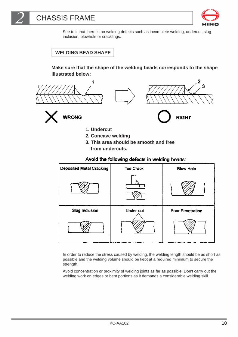
See to it that there is no welding defects such as incomplete welding, undercut, sluginclusion, blowhole or cracklings.
Make sure that the shape of the welding beads corresponds to the shapeillustrated below:
1. Undercut2. Concave welding3. This area should be smooth and free
from undercuts.
In order to reduce the stress caused by welding, the welding length should be as short aspossible and the welding volume should be kept at a required minimum to secure thestrength.
Avoid concentration or proximity of welding joints as far as possible. Don’t carry out thewelding work on edges or bent portions as it demands a considerable welding skill.
WELDING BEAD SHAPE
CHASSIS FRAME2
KC-AA102 10

The recommended welding current is shown as following table;
NOTE• Welding Current = Amp
• Diameter of welding rodØ3.2 (0.126 in) or Ø4 (0.157 in)
-----plate thinner than 5mm (0.197 in)Ø4 (0.157 in) or Ø5 (0.197 in)
-----plate thicker than 6mm (0.24 in)
CHASSIS FRAME2
KC-AA102 11
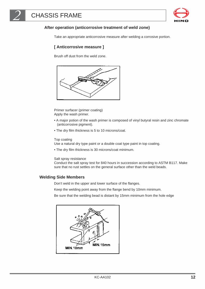
After operation (anticorrosive treatment of weld zone)
Take an appropriate anticorrosive measure after welding a corrosive portion.
[ Anticorrosive measure ]
Brush off dust from the weld zone.
Primer surfacer (primer coating)Apply the wash primer.
• A major potion of the wash primer is composed of vinyl butyral resin and zinc chromate(anticorrosive pigment).
• The dry film thickness is 5 to 10 microns/coat.
Top coatingUse a natural dry type paint or a double coat type paint in top coating.
• The dry film thickness is 30 microns/coat minimum.
Salt spray resistanceConduct the salt spray test for 840 hours in succession according to ASTM B117. Makesure that no rust settles on the general surface other than the weld beads.
Welding Side MembersDon’t weld in the upper and lower surface of the flanges.
Keep the welding point away from the flange bend by 10mm minimum.
Be sure that the welding bead is distant by 15mm minimum from the hole edge
CHASSIS FRAME2
KC-AA102 12

4. SIDE MEMBER REINFORCEMENT
The breakage or cracking of the side member is usually caused by stress concentrationdue to a local cut, welding or concentrated load or sudden rigidity change caused byupper parts rather than by the maximum stress which would be exerted in calculation.For this reason, the reinforcement by an outer or inner stiffener is not generally required.
• The large-scale repair of the side member should be avoided as far as possible.
• In the case where reinforcement is unavoidable due to special body or equipmentmounting (e.g. a small crane mounted behind the cab), modification or operating condi-tions, take adequate care of the following points.
Material of Reinforcing Member
When the outer side of the side member is reinforced, use a material at least equivalentto the main and inner materials.
In applying a reinforcing plate on the inside of the side member, use a general framesteel plate Hino standard SAPH440 with tensile strength of 440N/mm2 {45kgf/mm2} or anitem equivalent to SS41P
CHASSIS FRAME2
KC-AA102 13
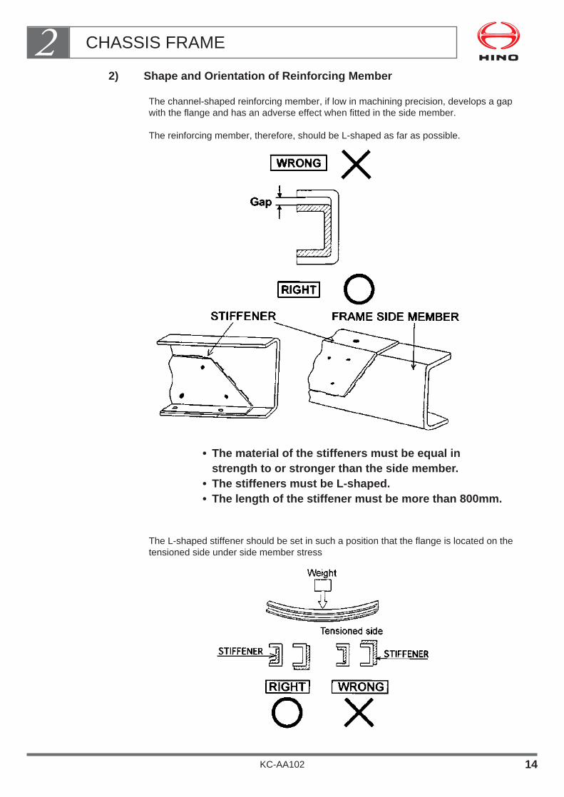
2) Shape and Orientation of Reinforcing Member
The channel-shaped reinforcing member, if low in machining precision, develops a gapwith the flange and has an adverse effect when fitted in the side member.
The reinforcing member, therefore, should be L-shaped as far as possible.
• The material of the stiffeners must be equal in strength to or stronger than the side member.
• The stiffeners must be L-shaped.• The length of the stiffener must be more than 800mm.
The L-shaped stiffener should be set in such a position that the flange is located on thetensioned side under side member stress
CHASSIS FRAME2
KC-AA102 14
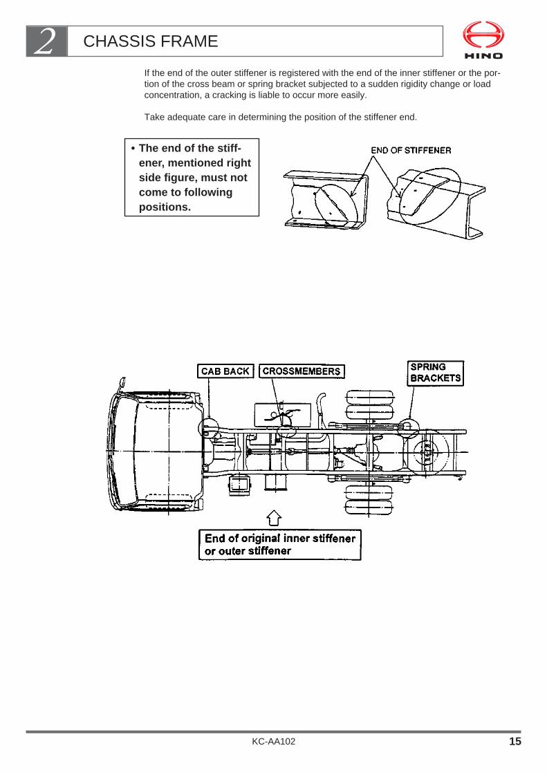
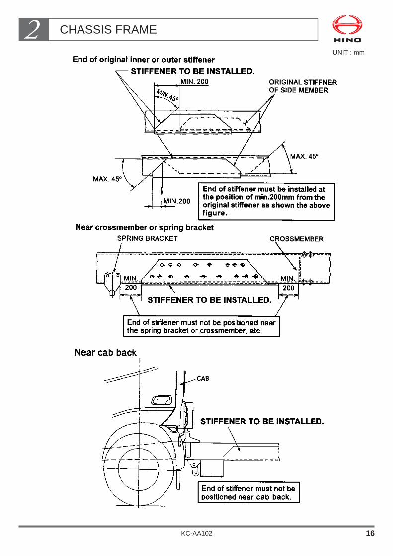
If the end of the outer stiffener is registered with the end of the inner stiffener or the por-tion of the cross beam or spring bracket subjected to a sudden rigidity change or loadconcentration, a cracking is liable to occur more easily.
Take adequate care in determining the position of the stiffener end.
• The end of the stiff-ener, mentioned rightside figure, must notcome to followingpositions.
CHASSIS FRAME2
KC-AA102 15
UNIT : mm
CHASSIS FRAME2
KC-AA102 16
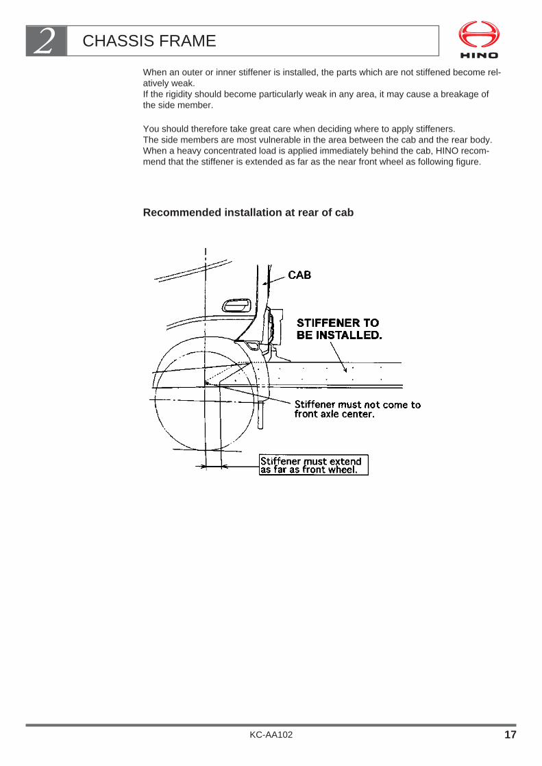
When an outer or inner stiffener is installed, the parts which are not stiffened become rel-atively weak.If the rigidity should become particularly weak in any area, it may cause a breakage ofthe side member.
You should therefore take great care when deciding where to apply stiffeners.The side members are most vulnerable in the area between the cab and the rear body.When a heavy concentrated load is applied immediately behind the cab, HINO recom-mend that the stiffener is extended as far as the near front wheel as following figure.
Recommended installation at rear of cab
CHASSIS FRAME2
KC-AA102 17
Avoiding Load Concentration
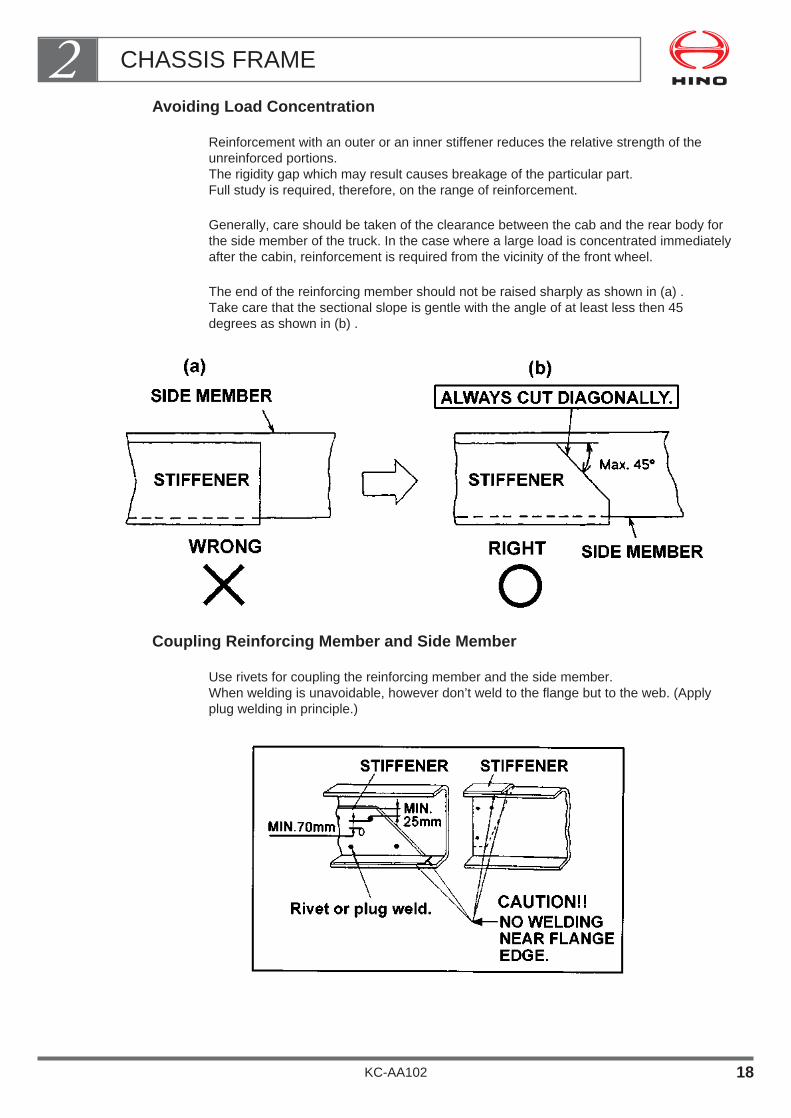
Reinforcement with an outer or an inner stiffener reduces the relative strength of theunreinforced portions.The rigidity gap which may result causes breakage of the particular part.Full study is required, therefore, on the range of reinforcement.
Generally, care should be taken of the clearance between the cab and the rear body forthe side member of the truck. In the case where a large load is concentrated immediatelyafter the cabin, reinforcement is required from the vicinity of the front wheel.
The end of the reinforcing member should not be raised sharply as shown in (a) .Take care that the sectional slope is gentle with the angle of at least less then 45degrees as shown in (b) .
Coupling Reinforcing Member and Side Member
Use rivets for coupling the reinforcing member and the side member.When welding is unavoidable, however don’t weld to the flange but to the web. (Applyplug welding in principle.)
CHASSIS FRAME2
KC-AA102 18

Before repeated riveting, correct the hole by drilling and apply a sufficient pressure.
• In the case where the number of sheets fastened is increased by setting a reinforcingmember, use a rivet having the next larger diameter.
• After riveting work, see that the rivet is not heated by gasflame or the like.
How to rivet, have to work as shown below.
In conducting the plug welding work, keep the plug-welding hole away from the end ofthe reinforcing member by 25mm minimum and from the bolt and the rivet hole by 70mmminimum.
• The hole diameter should be in the range of 14 to 20mm in principle
CHASSIS FRAME2
KC-AA102 19
5. OTHER PRECAUTIONS FOR DRILLING AND ELECTRICAL WELDING
Do Not Heat the Frame Unnecessarily
Heating greatly affects the strength of the frame.Do not unnecessarily heat any part of the frame unless performing welding work on theweb surface of the side member or gas cutting work on the rear overhang.
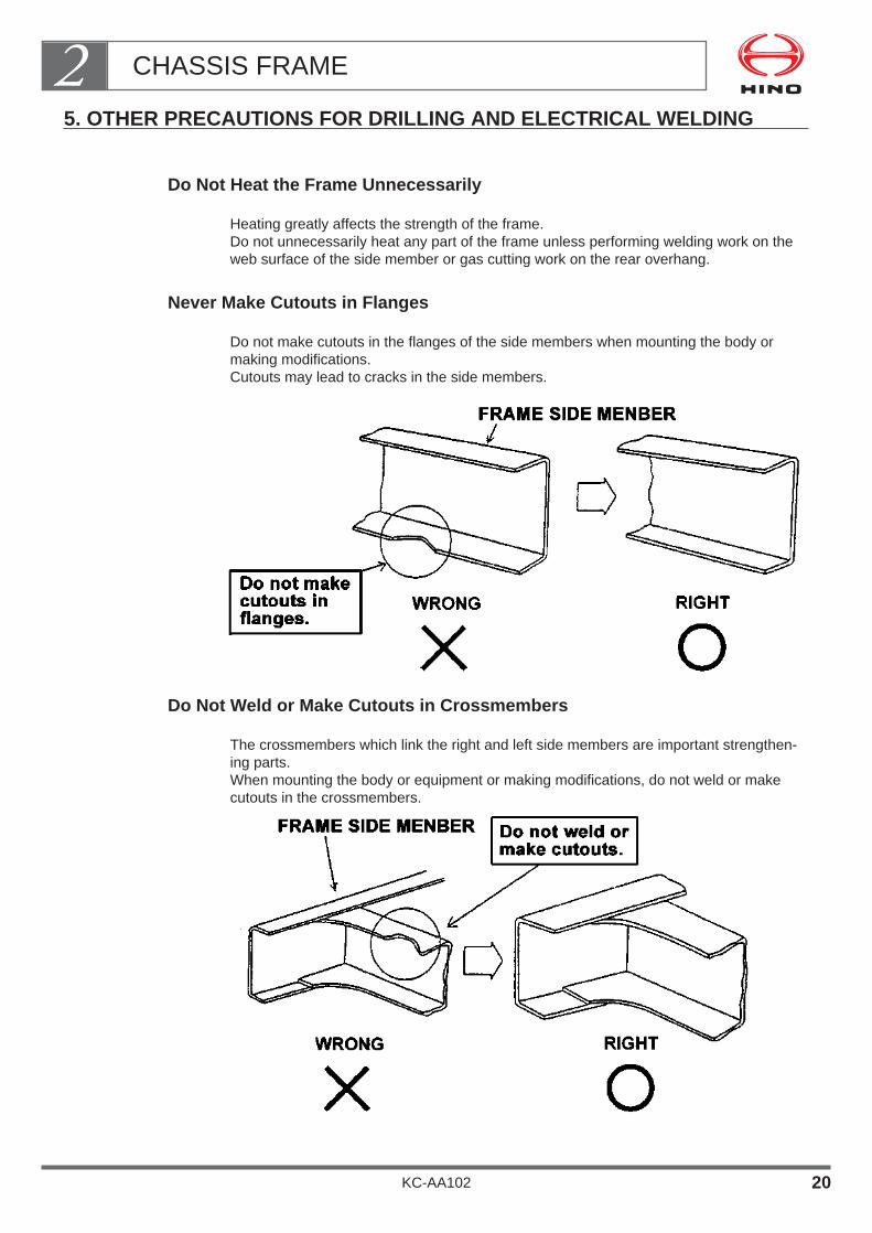
Never Make Cutouts in Flanges
Do not make cutouts in the flanges of the side members when mounting the body ormaking modifications.Cutouts may lead to cracks in the side members.
Do Not Weld or Make Cutouts in Crossmembers
The crossmembers which link the right and left side members are important strengthen-ing parts.When mounting the body or equipment or making modifications, do not weld or makecutouts in the crossmembers.
CHASSIS FRAME2
KC-AA102 20

Do Not Drill, Weld, or Make Cutouts in Stiffeners
The crossmembers are important strengthening parts which are fitted to avoid concen-trated loads on the side members.When mounting the body or equipment or making modifications, do not drill, weld, ormake cutouts in the stiffeners.
Do Not Modify the Crossmember
When accommodating body side devices within the chassis frame, you should not modifycrossmembers of the chassis frame.
If an equipment or a device comes across over the crossmember section or if a sufficientclearance is not available, apply an appropriate solution by moving the fitting position ofthe said equipment or device, etc.
CHASSIS FRAME2
KC-AA102 21

6. EXTENSION OF SIDE MEMBER REAR END
The rear end of the side member should be extended according to the method shown inthe figures below.
Extension by Welding
• The material of the extension must be the same as the base material of the main mem-bers and inner stiffeners.
• Extension length : 300mm maximum or less.
• Use a welding rod designed for use with the base metal.
• Use a continuous butt welding for the extension material and intermittent welding forstiffeners of 35mm in circumference.
NOTE• If demand for more than 300mm extension, please contact nearest
Hino sales dealer or distributor for information on how to extendthe rear end of the side member.
How to make an extension
Extension material
CHASSIS FRAME2
KC-AA102 22
7. MOUNTING A PART OH THE SIDE MEMBER
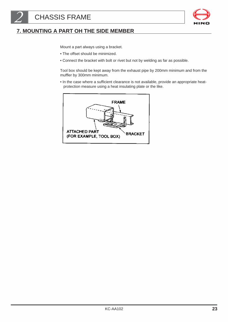
Mount a part always using a bracket.
• The offset should be minimized.
• Connect the bracket with bolt or rivet but not by welding as far as possible.
Tool box should be kept away from the exhaust pipe by 200mm minimum and from themuffler by 300mm minimum.
• In the case where a sufficient clearance is not available, provide an appropriate heat-protection measure using a heat insulating plate or the like.
CHASSIS FRAME2
KC-AA102 23

ENGINE AND ENGINE COMPARTMENT
1. PRECAUTIONS FOR MOUNTING OF BODY OR EQUIPMENT ・・・・・・・・・・・・・・・・・・・・・・・・・・ 2
KC-AA102
Chapter 3

• The engine is the most important component part of the vehicle.To ensure that it remains in optimum condition requires regularinspection, maintenance and repair work.
• When mounting a rear body or equipment, you should thereforeobserve the precautions and procedures described in this sectionand be sure to allow for ease of regular inspection, maintenanceand repair work.
ENGINE AND ENGINE COMPARTMENT3
KC-AA102 1
1. PRECAUTIONS FOR BODY OR EQUIPMENT MOUNTING
No Shared Fastening of Bolts.
The bolts making up the engine except for those used for the cylinder head and the sealsmust not be fastened together with the mounted or modified parts.
Ex: Fittings of intake manifold, water outlet and inlet, partsused with seals or gaskets.
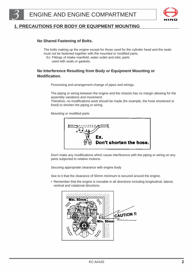
No Interference Resulting from Body or Equipment Mounting orModification.
Processing and arrangement change of pipes and wirings.
The piping or wiring between the engine and the chassis has no margin allowing for theassembly variations and movement.Therefore, no modifications work should be made (for example, the hose shortened orfixed) to shorten the piping or wiring.
Mounting or modified parts
Don't make any modifications which cause interference with the piping or wiring on anyparts subjected to relative motions.
Securing appropriate clearance with engine body
See to it that the clearance of 50mm minimum is secured around the engine.
• Remember that the engine is movable in all directions including longitudinal, lateral,vertical and rotational directions.
ENGINE AND ENGINE COMPARTMENT3
KC-AA102 2

Heat Consideration(piping and wiring, resin clamp, accelerator wire, fuel system, etc.)
When installing any of the above-described parts in the vicinity of the exhaust manifold,exhaust system, take adequate care of heat resistance.
• Secure a construction free of interference in case of assembly variations or clamp dis-location.In particular, secure a sufficient clearance for the accelerator wire from the heat source(150mm at minimum from the exhaust pipe).
• In the event that the defined clearance is unavailable, protect against heat by means ofa heat insulating plate or the like.
The resin clamp may be softened by the heat from the engine compartment and may bedislocated. Take good care.
ENGINE AND ENGINE COMPARTMENT3
KC-AA102 3

(3) Don't make any modifications which may cause an increased temperature ofintake air or fuel supplied to the injection pump.
Cooling
Don't make any mounting or modifications which may reduce the cooling performance.
Don't mount any parts at a position where the exhaust manifold is exposed to less air.
Don't change the fan shroud coverage on the fan nor add any fan shroud cut as it woulddeteriorate the cooling performance.
The seals (sponge, rubber plate and the like) around the radiator are mounted for thepurpose of securing the cooling performance. Don't remove them or cut a recess in them.
ENGINE AND ENGINE COMPARTMENT3
KC-AA102 4

Don't take off or cut the protector, cover, heat insulator or the like mounted around theengine.
No Modifications to Increase Intake or Exhaust Air Resistance
Don't make any modifications to the air cleaner.
Don't extend or make any modifications to the arrangement of the air hose.
Don't extend or make any modifications to the arrangement of the exhaust pipe.
Don't make any modifications to the muffler.
Mounting or Modifications of the Parts
Mounting on engine bodyIn mounting a part on the engine body, place it nearer to the engine (with a smaller over-hang) and reduce the weight as far as possible.
Mounting boltsMake sufficient study of the lap allowance and the bottom fitting of the bolt to be mount-ed.
Cooling fan belt changeDon't reduce the number of existing belts and avoid the case of a belt being shared.
ENGINE AND ENGINE COMPARTMENT3
KC-AA102 5

Pulley addition
• When adding a crank pulley, minimize the offset from the mounting position and reducethe weight as far as possible.
• Don't excessively advance the fan (coupling) as a result of pulley addition as it coulddeteriorate the durability of the water pump.
Taking Out of Auxiliary Power• Don't take auxiliary power out except crankshaft pulley and engine rear P. T. O.
Idling-Up Device• In the case to mount the engine idling-up device, make sure that don't change for the
worse of driving ability. (Ex; quick starting the vehicle, for the worse of engine brake,etc.)
Mounting and Dismounting Engine PartsIn reassembling an engine part, always make sure to comply with the Workshop Manualissued by the Hino Parts and Service Division. (Don't reuse the gasket, strictly conform tothe tightening torque requirement, etc.)
ServiceabilitySee to it that the following jobs are not adversely affected by the particular mounting ormodifications.• Oil level check• Oil change (oil drain or filling)• Change of oil filter• Adjustment of fan belt tension• Change of air cleaner element• Change of fuel filter• Adjustment of idle rpm, CO and HC• Adjustment of valve clearance• Adjustment of injection timing• Change of injection nozzle• Change of glow plug
ENGINE AND ENGINE COMPARTMENT3
KC-AA102 6

PROPELLER SHAFT
1. PROPELLER SHAFT ・・・・・・・・・・・・・・・・・・・・・・・・・・・・・・ 1
KC-AA102
Chapter 4
1. PROPELLER SHAFT
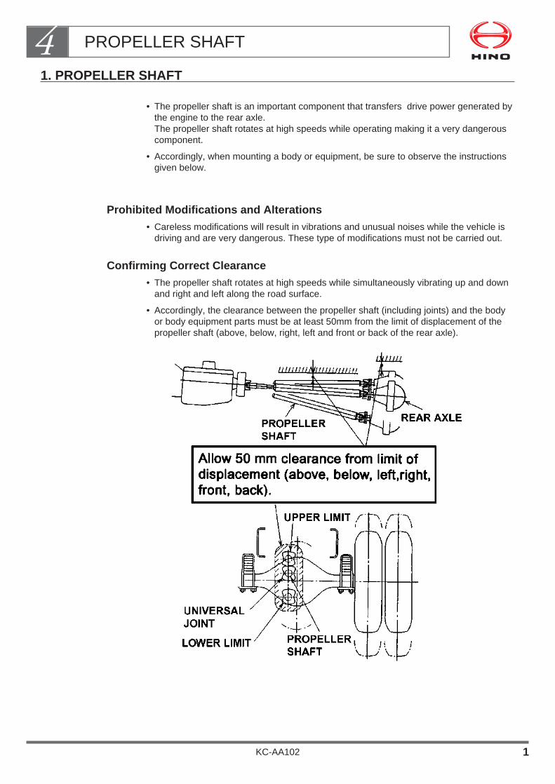
• The propeller shaft is an important component that transfers drive power generated bythe engine to the rear axle.The propeller shaft rotates at high speeds while operating making it a very dangerouscomponent.
• Accordingly, when mounting a body or equipment, be sure to observe the instructionsgiven below.
Prohibited Modifications and Alterations• Careless modifications will result in vibrations and unusual noises while the vehicle is
driving and are very dangerous. These type of modifications must not be carried out.
Confirming Correct Clearance• The propeller shaft rotates at high speeds while simultaneously vibrating up and down
and right and left along the road surface.
• Accordingly, the clearance between the propeller shaft (including joints) and the bodyor body equipment parts must be at least 50mm from the limit of displacement of thepropeller shaft (above, below, right, left and front or back of the rear axle).
PROPELLER SHAFT4
KC-AA102 1
BRAKE & HYDRAULIC PIPING
1. GENERAL POINTS OF BRAKE SYSTEM ・・・・・・・・・・・・ 2
2. BRAKE PIPING USED IN THE CHASSIS ・・・・・・・・・・・・ 5
3. PRECAUTIONS WHEN MOUNTING A BODY OR EQUIPMENT ・・・・・・・・・・・・・・・・・・・・・・・・・・・・・・・・ 6
4. PRECAUTIONS FOR MODIFICATION (ALTERATION)・・・・・・・・・・・・・・・・・・・・・・・・・・・・・・・・・・10
5. PIPING CLEARANCES ・・・・・・・・・・・・・・・・・・・・・・・・・・・・13
6. CLIPPING OF PIPING・・・・・・・・・・・・・・・・・・・・・・・・・・・・・・16
KC-AA102
Chapter 5

• The brake system is an extremely important safety component ofthe vehicle.
• Incorrect body or equipment mounting may have a major impact onthe functions and performance of the brake system and may lead toserious mechanical failures or accidents.
• When mounting a body or equipment or making alterations, strictlyobserve the following precautions:
BRAKE & HYDRAULIC PIPING5
KC-AA102 1

1. GENERAL POINTS OF BRAKE SYSTEM
Brake System Specifications• Hino vehicles are equipped with an assisted brake system that is matched to the size of
the vehicle to allow the driver to operate the brakes in safety and comfort.
The table below shows, in outline, how brake systems are matched to chassis models.
• If body equipment design means that you need to take power from the brake systemsuch as vacuum air pressure to control transmission PTO provided by body or equipmentmanufacturer, be sure to make a thoroughly study of the basic brake system before per-forming these modifications.
Do not Modify the Brake System
The brake system is the most important safety component of the vehicle and you mustnever modify it when mounting a body or equipment.
If you must modify the piping of the brake system in order to make other modifications tothe chassis during body or equipment mounting (moving the fuel tank, etc.) , please con-tact your nearest Hino sales dealer or distributor and follow the advice that the salesdealer or distributor provides.
BRAKE & HYDRAULIC PIPING5
KC-AA102 2
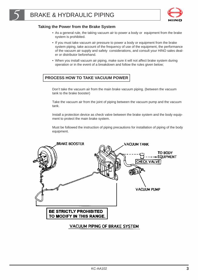
Taking the Power from the Brake System• As a general rule, the taking vacuum air to power a body or equipment from the brake
system is prohibited.
• If you must take vacuum air pressure to power a body or equipment from the brakesystem piping, take account of the frequency of use of the equipment, the performanceof the vacuum air supply and safety considerations, and consult your HINO sales deal-er or distributor beforehand.
• When you install vacuum air piping, make sure it will not affect brake system duringoperation or in the event of a breakdown and follow the rules given below;
Don’t take the vacuum air from the main brake vacuum piping. (between the vacuumtank to the brake booster)
Take the vacuum air from the joint of piping between the vacuum pump and the vacuumtank.
Install a protection device as check valve between the brake system and the body equip-ment to protect the main brake system.
Must be followed the instruction of piping precautions for installation of piping of the bodyequipment.
PROCESS HOW TO TAKE VACUUM POWER
BRAKE & HYDRAULIC PIPING5
KC-AA102 3
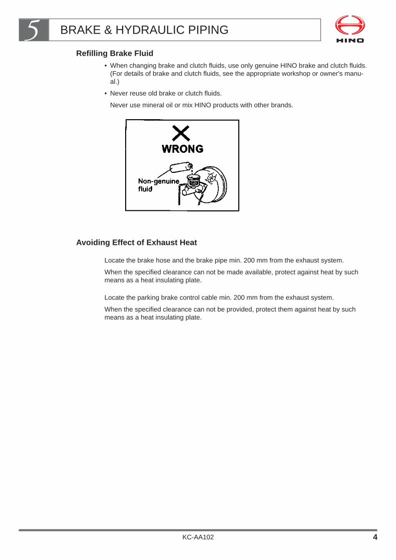
Refilling Brake Fluid• When changing brake and clutch fluids, use only genuine HINO brake and clutch fluids.
(For details of brake and clutch fluids, see the appropriate workshop or owner's manu-al.)
• Never reuse old brake or clutch fluids.
Never use mineral oil or mix HINO products with other brands.
Avoiding Effect of Exhaust Heat
Locate the brake hose and the brake pipe min. 200 mm from the exhaust system.
When the specified clearance can not be made available, protect against heat by suchmeans as a heat insulating plate.
Locate the parking brake control cable min. 200 mm from the exhaust system.
When the specified clearance can not be provided, protect them against heat by suchmeans as a heat insulating plate.
BRAKE & HYDRAULIC PIPING5
KC-AA102 4
2. BRAKE PIPING USED IN THE CHASSIS
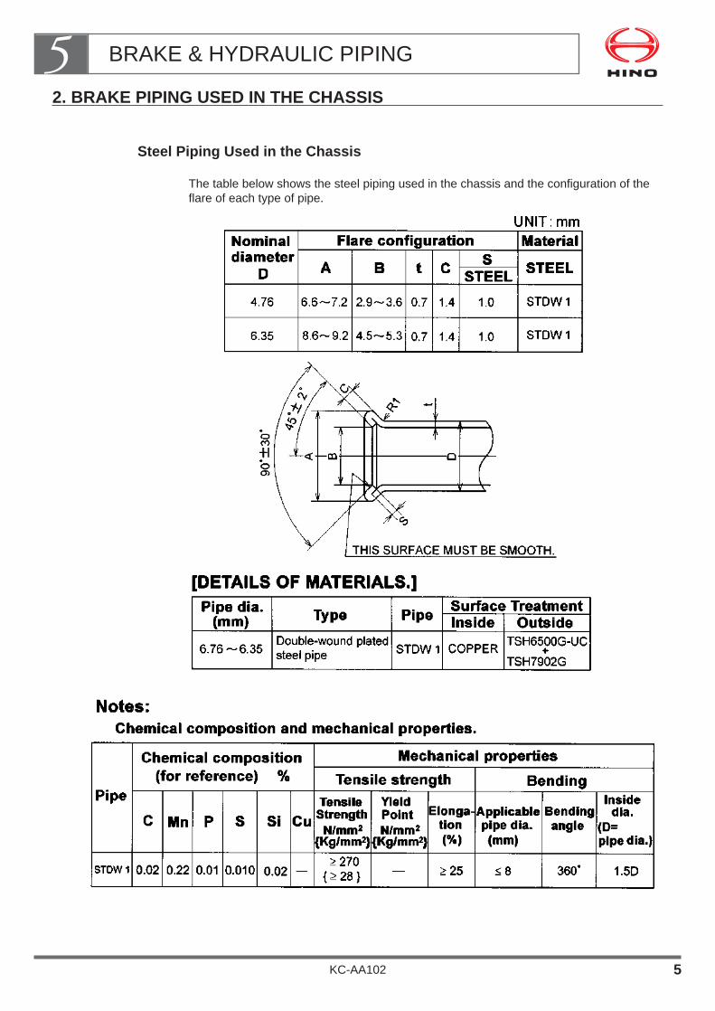
Steel Piping Used in the Chassis
The table below shows the steel piping used in the chassis and the configuration of theflare of each type of pipe.
BRAKE & HYDRAULIC PIPING5
KC-AA102 5
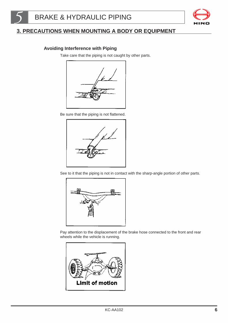
3. PRECAUTIONS WHEN MOUNTING A BODY OR EQUIPMENT
Avoiding Interference with PipingTake care that the piping is not caught by other parts.
Be sure that the piping is not flattened.
See to it that the piping is not in contact with the sharp-angle portion of other parts.
Pay attention to the displacement of the brake hose connected to the front and rearwheels while the vehicle is running.
BRAKE & HYDRAULIC PIPING5
KC-AA102 6
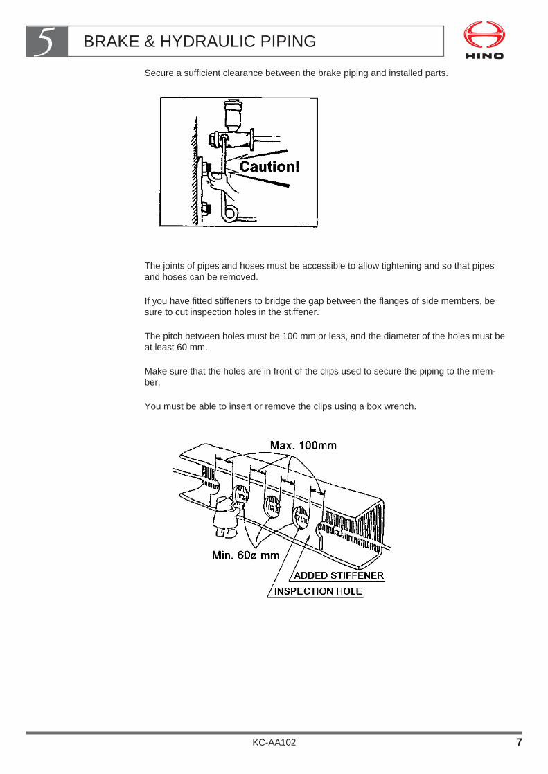
Secure a sufficient clearance between the brake piping and installed parts.
The joints of pipes and hoses must be accessible to allow tightening and so that pipesand hoses can be removed.
If you have fitted stiffeners to bridge the gap between the flanges of side members, besure to cut inspection holes in the stiffener.
The pitch between holes must be 100 mm or less, and the diameter of the holes must beat least 60 mm.
Make sure that the holes are in front of the clips used to secure the piping to the mem-ber.
You must be able to insert or remove the clips using a box wrench.
BRAKE & HYDRAULIC PIPING5
KC-AA102 7
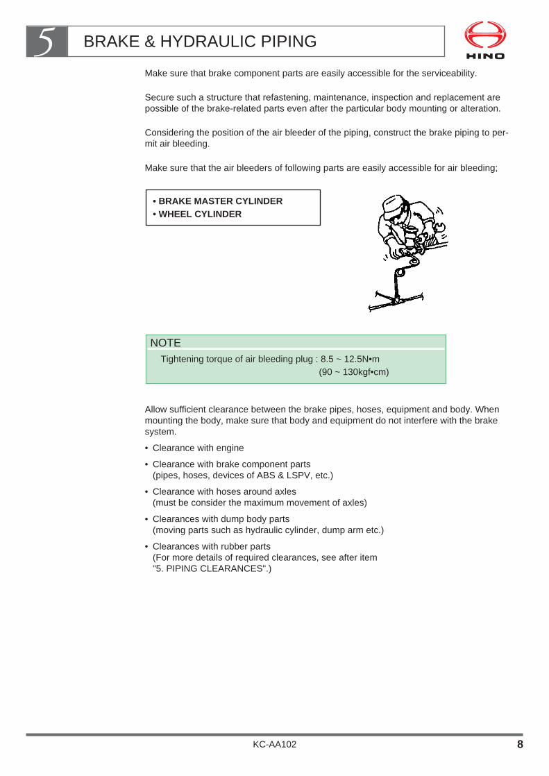
Make sure that brake component parts are easily accessible for the serviceability.
Secure such a structure that refastening, maintenance, inspection and replacement arepossible of the brake-related parts even after the particular body mounting or alteration.
Considering the position of the air bleeder of the piping, construct the brake piping to per-mit air bleeding.
Make sure that the air bleeders of following parts are easily accessible for air bleeding;
Allow sufficient clearance between the brake pipes, hoses, equipment and body. Whenmounting the body, make sure that body and equipment do not interfere with the brakesystem.
• Clearance with engine
• Clearance with brake component parts(pipes, hoses, devices of ABS & LSPV, etc.)
• Clearance with hoses around axles(must be consider the maximum movement of axles)
• Clearances with dump body parts(moving parts such as hydraulic cylinder, dump arm etc.)
• Clearances with rubber parts(For more details of required clearances, see after item "5. PIPING CLEARANCES".)
NOTETightening torque of air bleeding plug : 8.5 ~ 12.5N•m
(90 ~ 130kgf•cm)
• BRAKE MASTER CYLINDER• WHEEL CYLINDER
BRAKE & HYDRAULIC PIPING5
KC-AA102 8
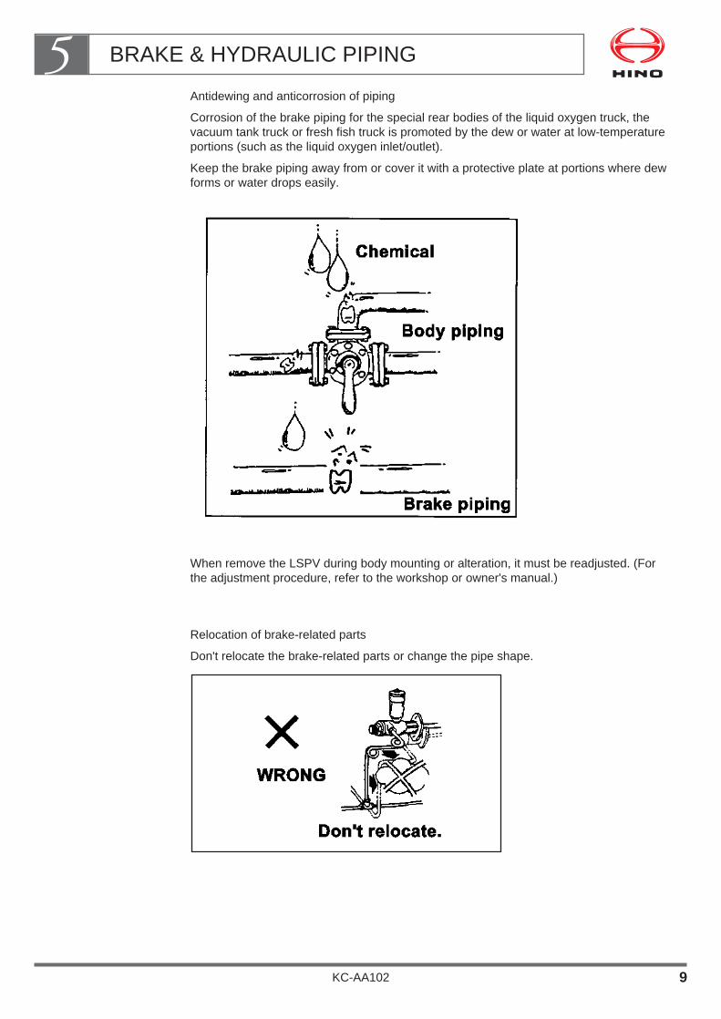
Antidewing and anticorrosion of piping
Corrosion of the brake piping for the special rear bodies of the liquid oxygen truck, thevacuum tank truck or fresh fish truck is promoted by the dew or water at low-temperatureportions (such as the liquid oxygen inlet/outlet).
Keep the brake piping away from or cover it with a protective plate at portions where dewforms or water drops easily.
When remove the LSPV during body mounting or alteration, it must be readjusted. (Forthe adjustment procedure, refer to the workshop or owner's manual.)
Relocation of brake-related parts
Don't relocate the brake-related parts or change the pipe shape.
BRAKE & HYDRAULIC PIPING5
KC-AA102 9
4. PRECAUTIONS FOR MODIFICATION (ALTERATION)
As far as possible avoid modifying any piping.
If you modify piping, be sure to observe the following precautions.
When extending a pipe, do not join two pipes directly.
When joining pipes, use the flare joint method and avoid twisting the pipes too much.
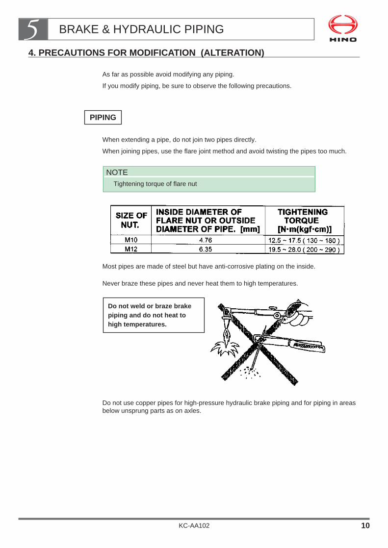
Most pipes are made of steel but have anti-corrosive plating on the inside.
Never braze these pipes and never heat them to high temperatures.
Do not use copper pipes for high-pressure hydraulic brake piping and for piping in areasbelow unsprung parts as on axles.
Do not weld or braze brakepiping and do not heat tohigh temperatures.
NOTETightening torque of flare nut
PIPING
BRAKE & HYDRAULIC PIPING5
KC-AA102 10
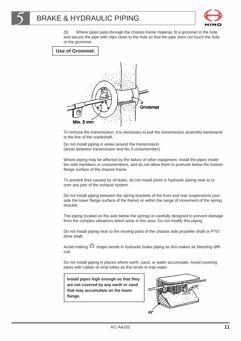
(5) Where pipes pass through the chassis frame material, fit a grommet in the holeand secure the pipe with clips close to the hole so that the pipe does not touch the holeor the grommet.
To remove the transmission, it is necessary to pull the transmission assembly backwardsin the line of the crankshaft.
Do not install piping in areas around the transmission(areas between transmission and No.3 crossmember).
Where piping may be affected by the failure of other equipment, install the pipes insidethe side members or crossmembers, and do not allow them to protrude below the bottomflange surface of the chassis frame.
To prevent fires caused by oil leaks, do not install joints in hydraulic piping near to orover any part of the exhaust system.
Do not install piping between the spring brackets of the front and rear suspensions (out-side the lower flange surface of the frame) or within the range of movement of the springshackle.
The piping located on the axle below the springs is carefully designed to prevent damagefrom the complex vibrations which arise in this area. Do not modify this piping.
Do not install piping near to the moving parts of the chassis side propeller shaft or PTOdrive shaft.
Avoid making shape bends in hydraulic brake piping as this makes air bleeding diffi-cult.
Do not install piping in places where earth, sand, or water accumulate. Avoid coveringpipes with rubber or vinyl tubes as this tends to trap water.
Install pipes high enough so that theyare not covered by any earth or sandthat may accumulate on the lowerflange.
Use of Grommet.
BRAKE & HYDRAULIC PIPING5
KC-AA102 11

To prevent from water, stone splashed by tire, locate the piping inside of frame or behindcrossmember.(must be away the piping min. 5mm from those parts)
Don’t locate the piping behind the end of the exhaust tail pipe.
When bending pipes, observe the following precautions:
• Use a bender and do not heat the pipes in order to bend them.
• Observe the standard bending radiuses shown in the table below.
• Make sure that the flat rate of deflection of the bending portion must be min. 80% of thepipe diameter.
• Flush the inside of the pipe and remove any foreign matter before use. Use com-pressed air to flush the pipe.
• For details of pipe machining at the flare nut, see item 2 of this section, "Brake PipingUsed in the Chassis".After machining, remove any foreign matter by flushing the pipe with compressed air.
Make sure that there are not to much slack and giving tension to the piping.
BRAKE & HYDRAULIC PIPING5
KC-AA102 12
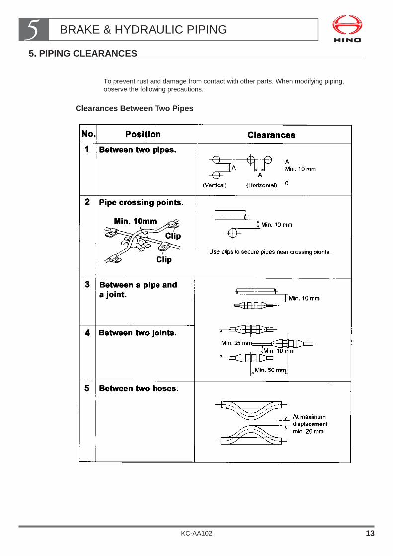
5. PIPING CLEARANCES
To prevent rust and damage from contact with other parts. When modifying piping,observe the following precautions.
Clearances Between Two Pipes
BRAKE & HYDRAULIC PIPING5
KC-AA102 13
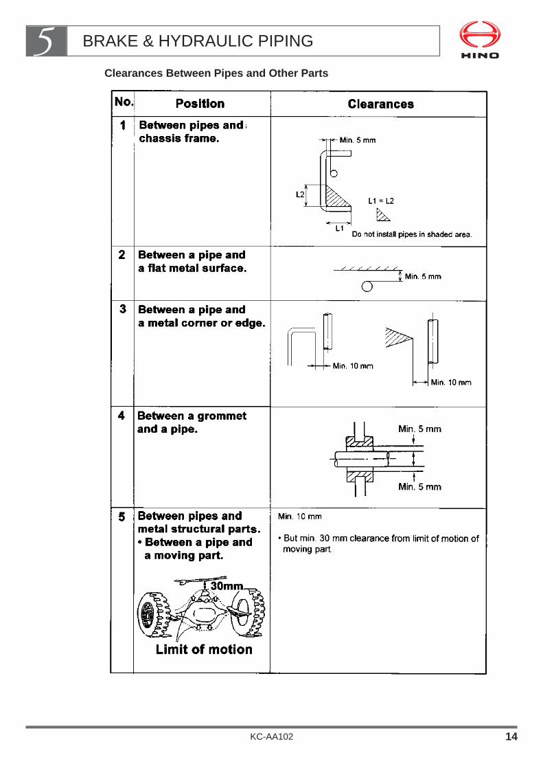
Clearances Between Pipes and Other Parts
BRAKE & HYDRAULIC PIPING5
KC-AA102 14
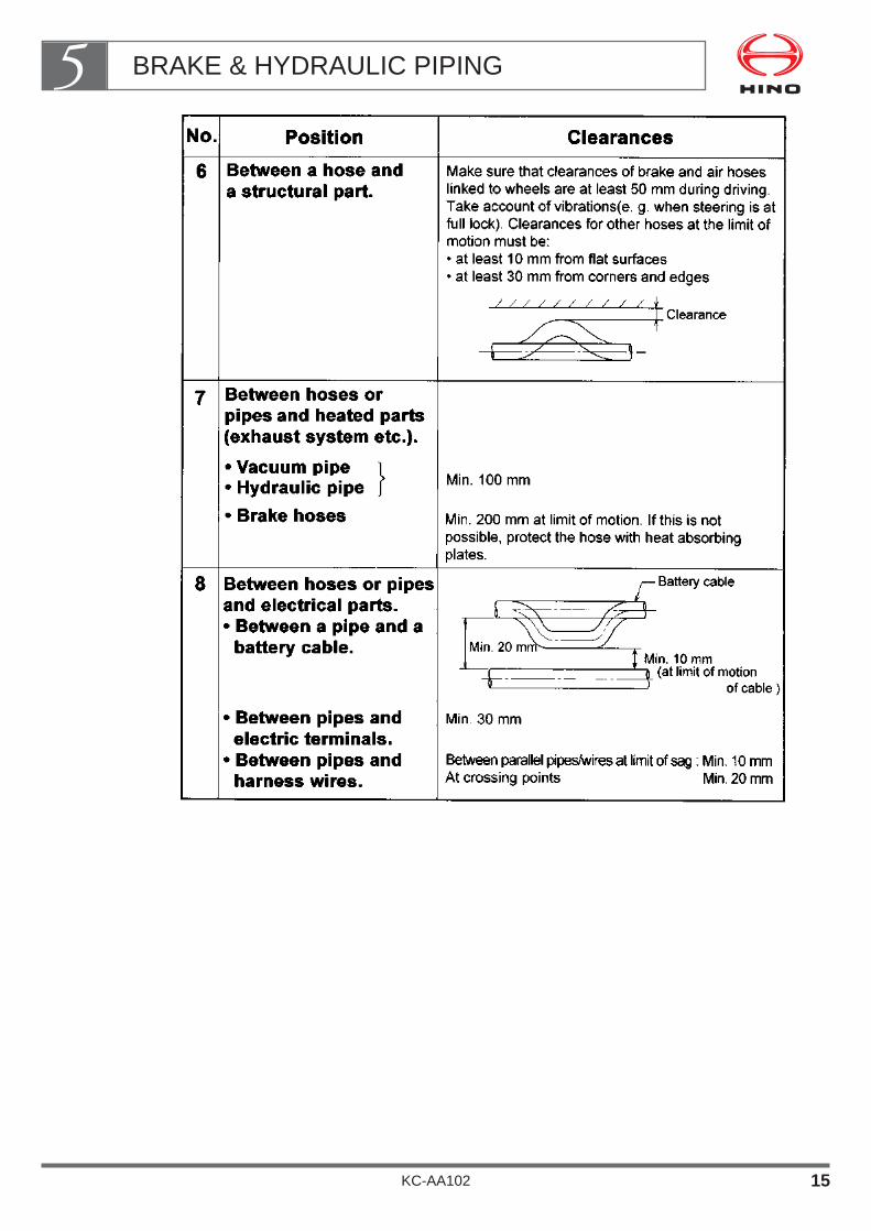
BRAKE & HYDRAULIC PIPING5
KC-AA102 15

6. CLIPPING OF PIPING
Pipes must be secured with clips to prevent them from swinging due to the motion of thevehicle.
Use vinyl-coated or rubber-coated clips and follow the rules given in the table below.
BRAKE & HYDRAULIC PIPING5
KC-AA102 16

FUEL TANK
1. PRECAUTIONS FOR RELOCATING THE FUEL TANK ・・・・・・・・・・・・・・・・・・・・・・・・・・・・・・・・・・・・ 2
2. MODIFICATION OR ADDITION OF FUEL TANK ・・・・・・ 8
3. OTHER NOTES ON RELOCATING OR ADDING THE FUEL TANK ・・・・・・・・・・・・・・・・・・・・ 9
KC-AA102
Chapter 6

• For the purposes of mounting a body or equipment, or in order toadapt a vehicle for long-distance driving, you may need to move thefuel tank or mount an additional fuel tank.
• If you intend to move or add a fuel tank, be sure to observe the fol-lowing procedures.
WARNING
Incorrect modifications may lead to vehicle fires.
FUEL TANK6
KC-AA102 1

1. PRECAUTIONS FOR RELOCATING THE FUEL TANK
When relocating the fuel tank, be sure to observe the following procedures:
If you intend to relocate making longer or shorter the fuel lines, be sure to use the speci-fied fuel hose or steel pipe that came with base vehicle.
Vinyl chloride hoseDo not use vinyl chloride hose for the feed and fuel line.
Rubber hoseUse rubber hose for the fuel feed and return line.
• Never use hose of vinyl chloride instead of rubber hose.
• Connected with rubber hose and vinyl chloride hose is prohibited.
• Never use vinyl chloride hose for the fuel return line.
• Using defective polyvinyl chloride or rubber hoses can lead to vehicle fires. Always usegenuine HINO parts.
WARNING
FUEL TANK6
KC-AA102 2
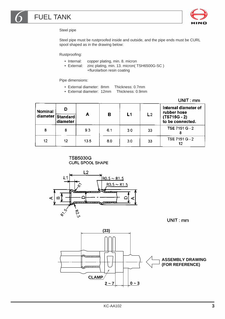
Steel pipe
Steel pipe must be rustproofed inside and outside, and the pipe ends must be CURLspool shaped as in the drawing below:
Rustproofing:
• Internal: copper plating, min. 8. micron• External: zinc plating, min. 13. micron( TSH6500G-SC )
+flurolarbon resin coating
Pipe dimensions:
• External diameter: 8mm Thickness: 0.7mm• External diameter: 12mm Thickness: 0.9mm
(33)
ASSEMBLY DRAWING(FOR REFERENCE)
CLAMP2 ~ 7 0 ~ 3
FUEL TANK6
KC-AA102 3
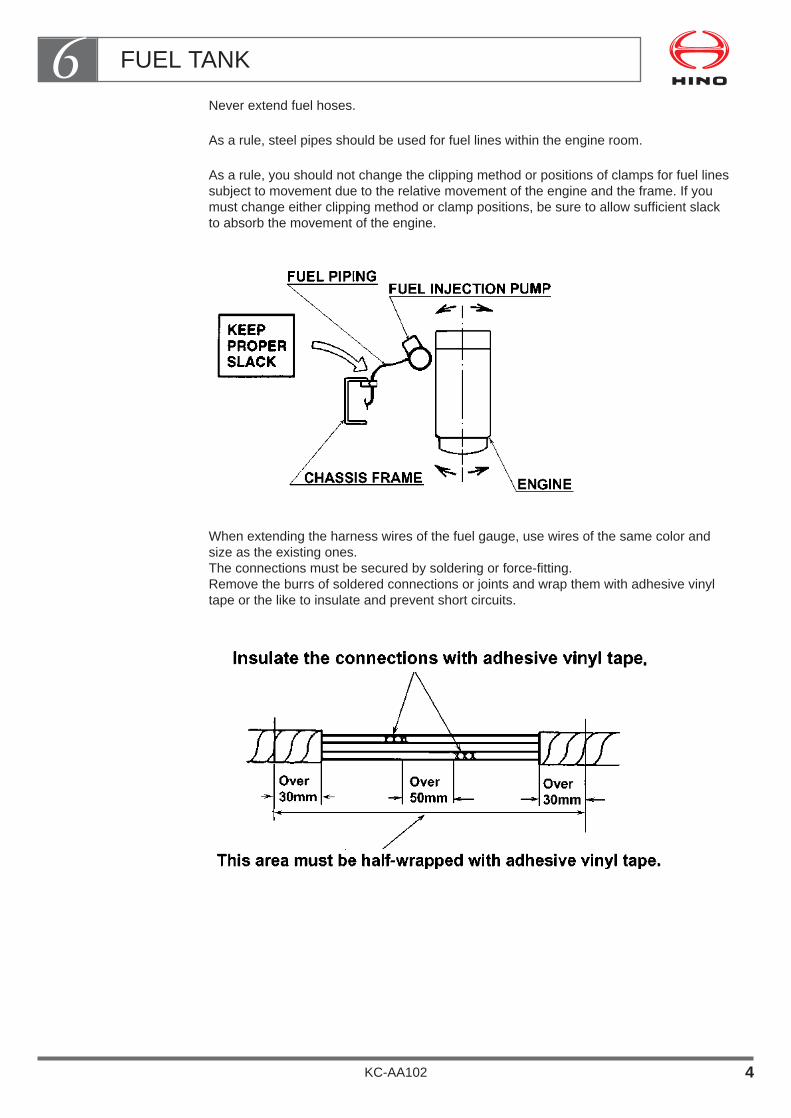
Never extend fuel hoses.
As a rule, steel pipes should be used for fuel lines within the engine room.
As a rule, you should not change the clipping method or positions of clamps for fuel linessubject to movement due to the relative movement of the engine and the frame. If youmust change either clipping method or clamp positions, be sure to allow sufficient slackto absorb the movement of the engine.
When extending the harness wires of the fuel gauge, use wires of the same color andsize as the existing ones.The connections must be secured by soldering or force-fitting.Remove the burrs of soldered connections or joints and wrap them with adhesive vinyltape or the like to insulate and prevent short circuits.
FUEL TANK6
KC-AA102 4

If you shorten the harness wires, bundle up the excess length, half-wrap it with adhesivevinyl tape and fasten it securely using clips fitted to the fuel tank mounting band.
For clearances between the exhaust system, fuel tank, and fuel hoses, must be kept200mm or more away.
• If it is impossible to allow a 200mm or larger clearance between them, install a thermalinsulation plate to protect the fuel tank and hoses.
• The hose near the high-temperature component swells and is deteriorated so much asto may slip out.Never connect the hose in such an area.
• Details of clearances with the exhaust system, see clause "EXHAUST SYSTEM".
Make sure that even in the event of a fuel leak, fuel will not drip onto any part of theexhaust system. Joints must not be positioned above any part of the exhaust system.
Joints in the fuel hoses must be inserted by at least 30mm and gripped securely in thecenter by a clamp.
(33)CLAMP
2 ~ 7 0 ~ 3
FUEL PIPE
FUEL HOSE
FUEL TANK6
KC-AA102 5
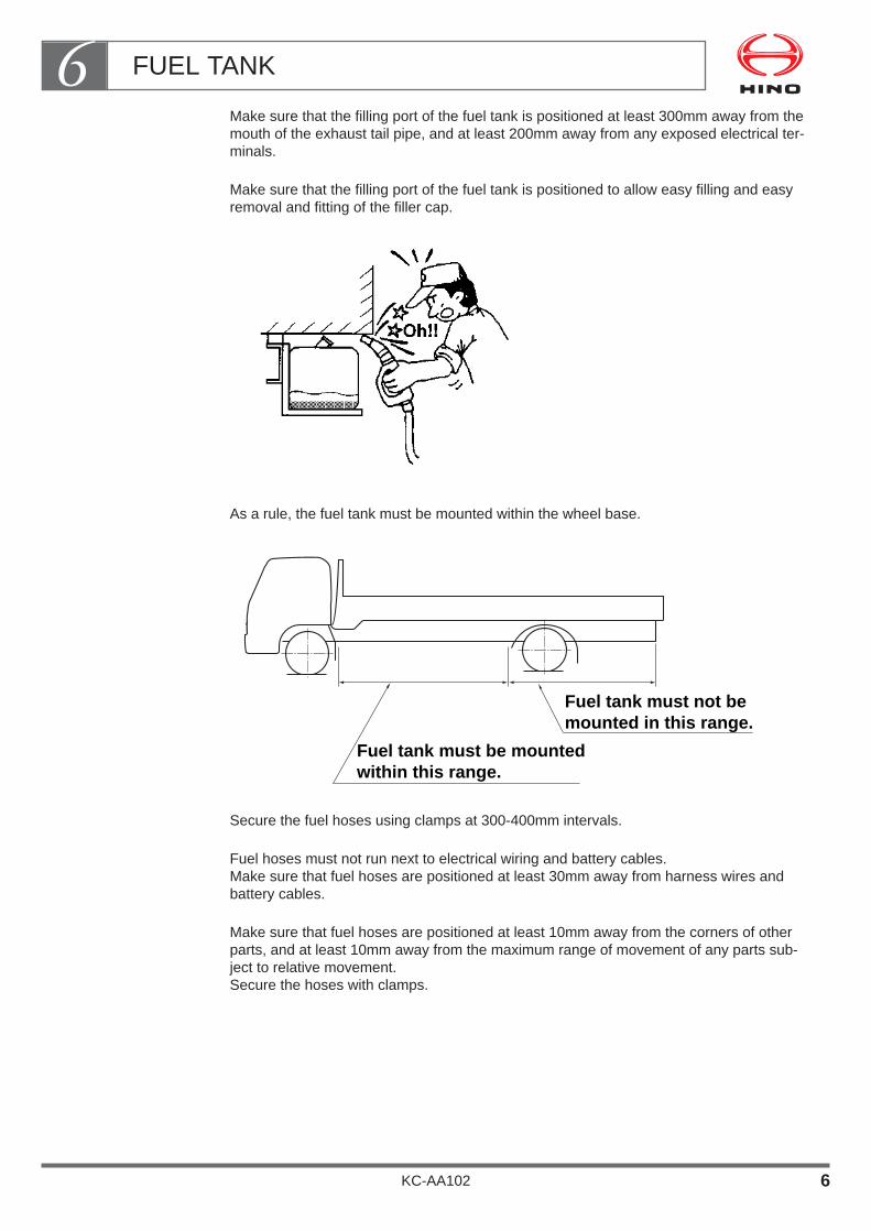
Make sure that the filling port of the fuel tank is positioned at least 300mm away from themouth of the exhaust tail pipe, and at least 200mm away from any exposed electrical ter-minals.
Make sure that the filling port of the fuel tank is positioned to allow easy filling and easyremoval and fitting of the filler cap.
As a rule, the fuel tank must be mounted within the wheel base.
Secure the fuel hoses using clamps at 300-400mm intervals.
Fuel hoses must not run next to electrical wiring and battery cables.Make sure that fuel hoses are positioned at least 30mm away from harness wires andbattery cables.
Make sure that fuel hoses are positioned at least 10mm away from the corners of otherparts, and at least 10mm away from the maximum range of movement of any parts sub-ject to relative movement.Secure the hoses with clamps.
Fuel tank must be mountedwithin this range.
Fuel tank must not bemounted in this range.
FUEL TANK6
KC-AA102 6

When using the vehicle’s main fuel tank to supply fuel to the engine of a refrigerator orother equipment, be sure that the fuel for this engine is taken directly from the main fueltank.
Never take a line from the main fuel feed system as this will interfere with the mainengine fuel supply.
Install the relocated tank securely so that its bands do not become loose or the tank itselfdoes not move due to vibrations caused while the vehicle is running.
When fabricating a new mounting bracket for the relocated or additional fuel tank, it musthave a shape that can resist the vibrations and movements caused while the vehicle isrunning.
Make sure that the fuel tank must be relocated to the place where do not interfere withtire chain.
FUEL TANK6
KC-AA102 7
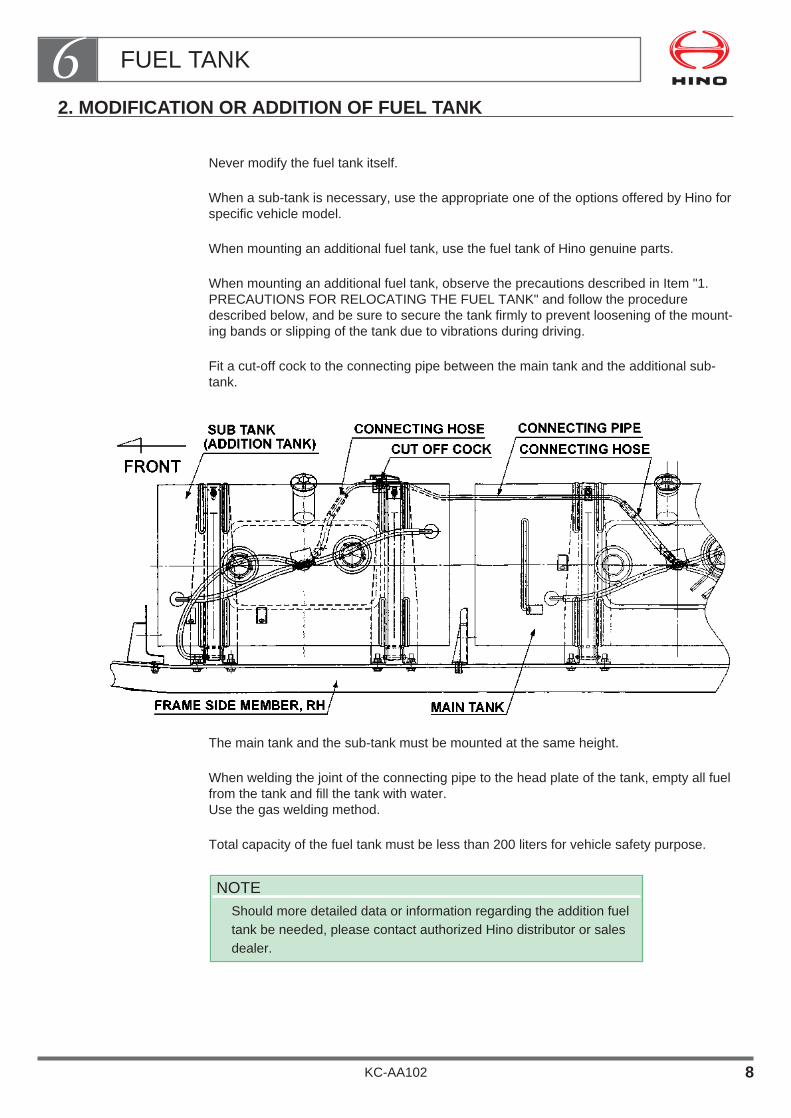
2. MODIFICATION OR ADDITION OF FUEL TANK
Never modify the fuel tank itself.
When a sub-tank is necessary, use the appropriate one of the options offered by Hino forspecific vehicle model.
When mounting an additional fuel tank, use the fuel tank of Hino genuine parts.
When mounting an additional fuel tank, observe the precautions described in Item "1.PRECAUTIONS FOR RELOCATING THE FUEL TANK" and follow the proceduredescribed below, and be sure to secure the tank firmly to prevent loosening of the mount-ing bands or slipping of the tank due to vibrations during driving.
Fit a cut-off cock to the connecting pipe between the main tank and the additional sub-tank.
The main tank and the sub-tank must be mounted at the same height.
When welding the joint of the connecting pipe to the head plate of the tank, empty all fuelfrom the tank and fill the tank with water.Use the gas welding method.
Total capacity of the fuel tank must be less than 200 liters for vehicle safety purpose.
NOTEShould more detailed data or information regarding the addition fueltank be needed, please contact authorized Hino distributor or salesdealer.
FUEL TANK6
KC-AA102 8

3. OTHER NOTES ON RELOCATING OR ADDING THE FUEL TANKS
The original clearance between the fuel tank and the frame allows space for U-bolts usedin body mounting.
When moving the fuel tank or mounting an additional fuel tank, make sure that you allowspace for these U-bolts.
When moving the fuel tank or mounting an additional fuel tank, make sure that it does notprotrude beyond the overall width of the vehicle.
In vehicles for export from Japan, a pre-fuel filter and sedimenter are fitted to the framealong with the fuel tank to suit conditions of use.
When moving the fuel tank or mounting an additional fuel tank, make sure that youarrange the piping of these parts correctly
Fuel tanks must be mounted outside the locus of the bending radius of the fender to pre-vent them from interfering with the tire.
The original bracket for the fuel tank is designed to support the weight of the tank.
Never mount body parts or side guard parts on the fuel tank bracket.
When moving the fuel tank or mounting an additional fuel tank, mount the bracket on theframe using bolts.
Never use welding.(When making holes in the frame for mounting the bracket, see "Drilling the frame" underclause " 2. CHASSIS FRAME")
Fit protectors to ensure that the carrying load does not come into contact with the fueltank or any part of the piping.
FUEL TANK6
KC-AA102 9

ELECTRICAL SYSTEM
1. REAR LAMPS ・・・・・・・・・・・・・・・・・・・・・・・・・・・・・・・・・・・・ 2
2. BACK-UP BUZZER ・・・・・・・・・・・・・・・・・・・・・・・・・・・・・・・・ 7
3. SIDE REFLECTOR ・・・・・・・・・・・・・・・・・・・・・・・・・・・・・・・・ 8
4. ALTERNATOR OUTPUT CHARACTERISTIC ・・・・・・・・ 9
5. SPARE POWER TERMINALS ・・・・・・・・・・・・・・・・・・・・・・11
6. INSTALLATION OF ADDITIONAL EQUIPMENT AND SWITCHES ・・・・・・・・・・・・・・・・・・・・・・・・・・・・・・・・21
7. ADDITIONAL LAMPS ・・・・・・・・・・・・・・・・・・・・・・・・・・・・・・24
8. DRAWING IN THE WIRE HARNESS INTO THE CAB ・・・・・・・・・・・・・・・・・・・・・・・・・・・・・・・・・・・・・・・・・・27
9. POINTS TO NOTE ON ELECTRICAL WELDING ・・・・・・28
10. POINTS TO NOTE FOR ELECTRONIC MACHINES ・・・・・・・・・・・・・・・・・・・・・・・・・・・・・・・・・・・・30
11. HARNESS WIRING ・・・・・・・・・・・・・・・・・・・・・・・・・・・・・・・・32
12. ELECTRIC WIRE SIZE AND PERMISSIBLE CURRENTS ・・・・・・・・・・・・・・・・・・・・・・42
13. ELECTRICAL WIRING DIAGRAM ・・・・・・・・・・・・・・・・・・44
KC-AA102
Chapter 7

The chassis is usually shipped from the factory with brackets for therear combination lamps and rear license plate temporarily fitted.
At the time of mounting a body or equipment, make sure youobserve the following precautions to fit these electrical parts orother electrical component to the body or equipment.
Warning• Mounting an excessive number of lamps or taking-out electrical
power for a body or equipment can damage the electrical systemsand may lead to burnouts of the harness wires.
In the event that you are obliged to carry out the body mountingexceeding the capacity of the alternator, consult to Hino distributoror sales dealer.
• The parts number described in each page will be changed withoutforward notice.
Therefore, consult to Hino distributor or sales dealer with regard tothe exact parts number.
ELECTRICAL SYSTEM7
KC-AA102 1
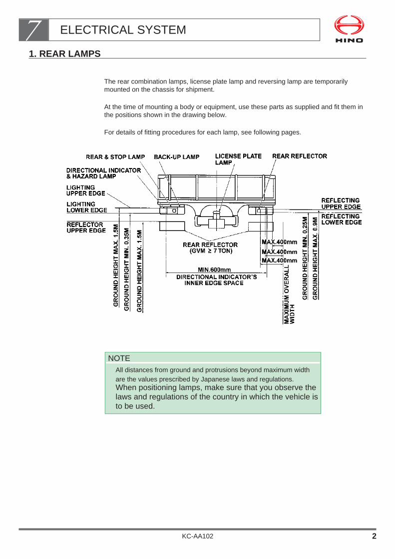
1. REAR LAMPS
The rear combination lamps, license plate lamp and reversing lamp are temporarilymounted on the chassis for shipment.
At the time of mounting a body or equipment, use these parts as supplied and fit them inthe positions shown in the drawing below.
For details of fitting procedures for each lamp, see following pages.
NOTEAll distances from ground and protrusions beyond maximum widthare the values prescribed by Japanese laws and regulations.When positioning lamps, make sure that you observe thelaws and regulations of the country in which the vehicle isto be used.
ELECTRICAL SYSTEM7
KC-AA102 2
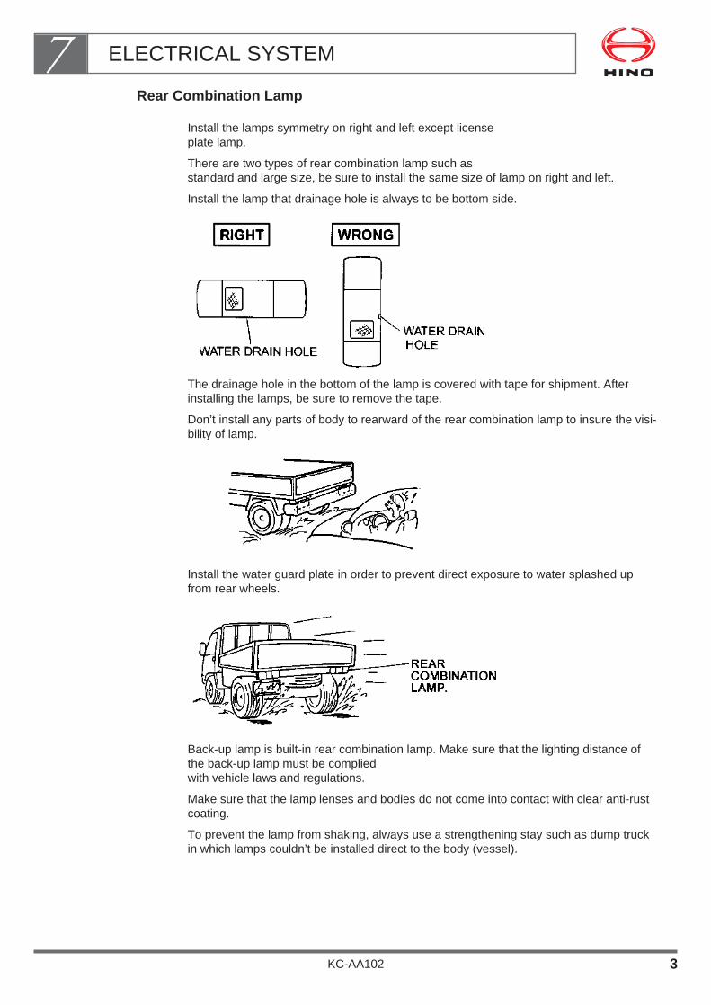
Rear Combination Lamp
Install the lamps symmetry on right and left except license plate lamp.
There are two types of rear combination lamp such as standard and large size, be sure to install the same size of lamp on right and left.
Install the lamp that drainage hole is always to be bottom side.
The drainage hole in the bottom of the lamp is covered with tape for shipment. Afterinstalling the lamps, be sure to remove the tape.
Don’t install any parts of body to rearward of the rear combination lamp to insure the visi-bility of lamp.
Install the water guard plate in order to prevent direct exposure to water splashed upfrom rear wheels.
Back-up lamp is built-in rear combination lamp. Make sure that the lighting distance ofthe back-up lamp must be complied with vehicle laws and regulations.
Make sure that the lamp lenses and bodies do not come into contact with clear anti-rustcoating.
To prevent the lamp from shaking, always use a strengthening stay such as dump truckin which lamps couldn’t be installed direct to the body (vessel).
ELECTRICAL SYSTEM7
KC-AA102 3
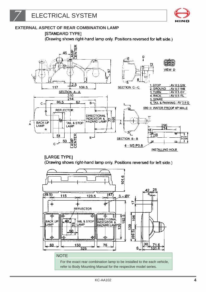
EXTERNAL ASPECT OF REAR COMBINATION LAMP
NOTEFor the exact rear combination lamp to be installed to the each vehicle,refer to Body Mounting Manual for the respective model series.
ELECTRICAL SYSTEM7
KC-AA102 4

License Plate Bracket and License Plate Lamp
Use the bracket supplied with the chassis to install the license plate and license platelamp.
The license plate must be installed so as to be clearly visible from the rear of the vehicle.
Make sure that it is not hidden by the rear bumper, lamps, or by the rear body or mounted equipment.
The license plate bracket must be securely installed by rivets or bolts so as to be complied with vehicle laws and regulations.
To prevent the license plate bracket from shaking, always use a strengthening stay when it is installed.
Make sure that light of the license lamp do not directly come through toward the rear ofthe vehicle.
Mount the license lamp at such a position where it is not exposed directly to the watersplashed by the rear wheels.
ELECTRICAL SYSTEM7
KC-AA102 5
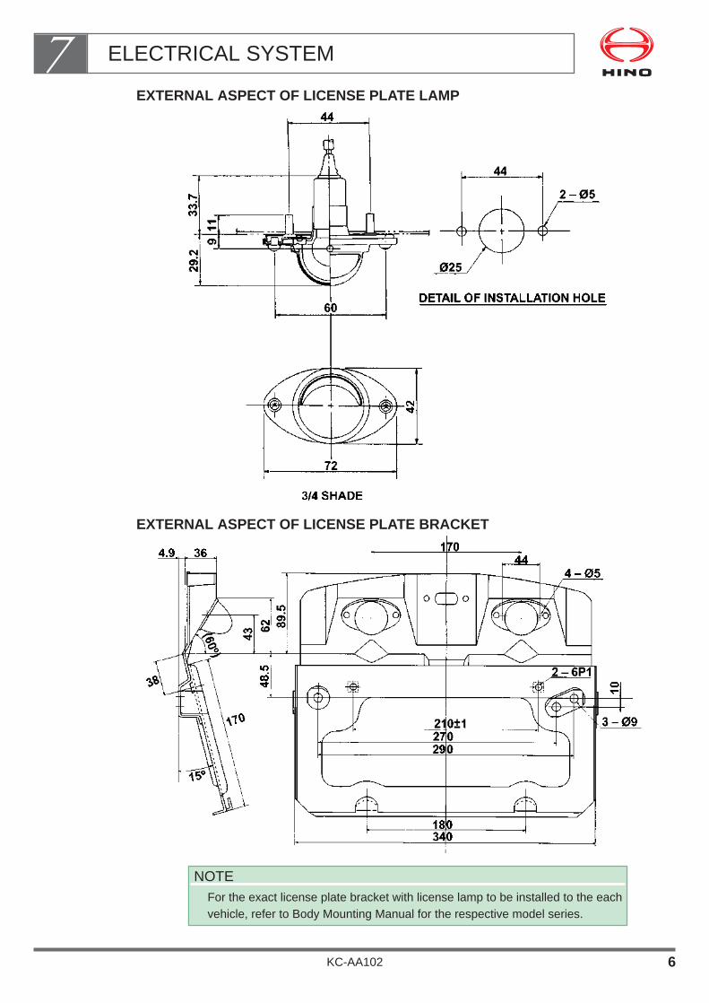
EXTERNAL ASPECT OF LICENSE PLATE LAMP
EXTERNAL ASPECT OF LICENSE PLATE BRACKET
NOTEFor the exact license plate bracket with license lamp to be installed to the eachvehicle, refer to Body Mounting Manual for the respective model series.
ELECTRICAL SYSTEM7
KC-AA102 6
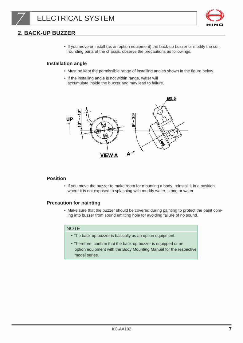
2. BACK-UP BUZZER
• If you move or install (as an option equipment) the back-up buzzer or modify the sur-rounding parts of the chassis, observe the precautions as followings.
Installation angle• Must be kept the permissible range of installing angles shown in the figure below.
• If the installing angle is not within range, water will accumulate inside the buzzer and may lead to failure.
Position• If you move the buzzer to make room for mounting a body, reinstall it in a position
where it is not exposed to splashing with muddy water, stone or water.
Precaution for painting• Make sure that the buzzer should be covered during painting to protect the paint com-
ing into buzzer from sound emitting hole for avoiding failure of no sound.
NOTE• The back-up buzzer is basically as an option equipment.
• Therefore, confirm that the back-up buzzer is equipped or an option equipment with the Body Mounting Manual for the respectivemodel series.
ELECTRICAL SYSTEM7
KC-AA102 7
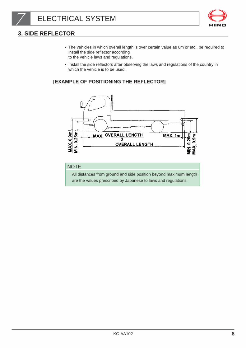
3. SIDE REFLECTOR
• The vehicles in which overall length is over certain value as 6m or etc., be required toinstall the side reflector according to the vehicle laws and regulations.
• Install the side reflectors after observing the laws and regulations of the country inwhich the vehicle is to be used.
[EXAMPLE OF POSITIONING THE REFLECTOR]
NOTE
All distances from ground and side position beyond maximum length
are the values prescribed by Japanese to laws and regulations.
ELECTRICAL SYSTEM7
KC-AA102 8

4. ALTERNATOR OUTPUT CHARACTERISTIC
• The maximum power available for the whole vehicle is defined by the capacity of thealternator.
Therefore, the electric power that is not consumed by electrical equipments such ashead lamps etc. can be available for the body side.
• Pay attention not to exceed the capacity of the alternator equipped on the vehicle.
• In the event that you are obliged to carry out the body mounting exceeding the capacityof the alternator, select the one available as an option or consult your nearest Hinosales dealer or distributor.
• Alternator output characteristic of each engine model are described as follows for yourreference.
The details of the performance (output characteristic) of alternator to be installed eachvehicle, see the Body Mounting Manual for the respective model.
ELECTRICAL SYSTEM7
KC-AA102 9
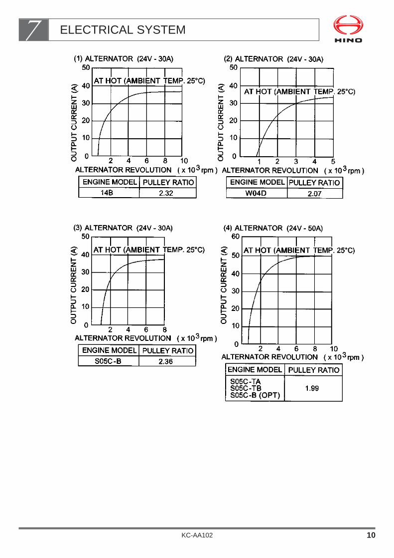
ELECTRICAL SYSTEM7
KC-AA102 10

5. SPARE POWER CONNECTORS
If you must take an electrical power supply for the body or equipment from the chassis,take it from the spare power supply connector.
Install Position of Relay and FuseThe relay and fuse are installed as following position in the cab.
[RIGHT - HAND DRIVE]
[LEFT - HAND DRIVE]
NOTE• Drawing shows of the standard cab specification vehicle as example.• For details, refer to Body Mounting Manual for the respective model series.
ELECTRICAL SYSTEM7
KC-AA102 11

Fuse block layout
NOTE• Fuse block layout as mentioned above shows as example.• For details, refer to the Body Mounting Manual for the respective model series.
ELECTRICAL SYSTEM7
KC-AA102 12
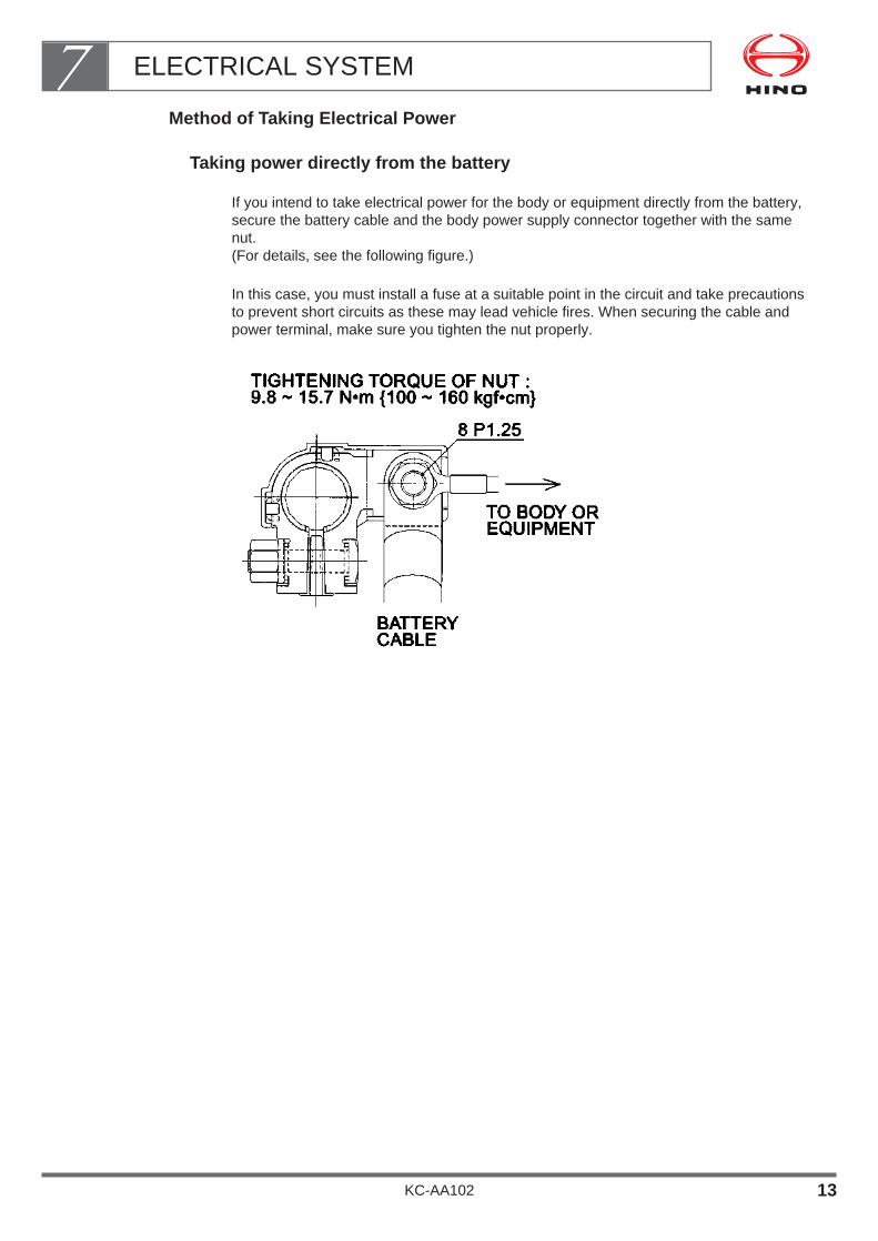
Method of Taking Electrical Power
Taking power directly from the battery
If you intend to take electrical power for the body or equipment directly from the battery,secure the battery cable and the body power supply connector together with the samenut.(For details, see the following figure.)
In this case, you must install a fuse at a suitable point in the circuit and take precautionsto prevent short circuits as these may lead vehicle fires. When securing the cable andpower terminal, make sure you tighten the nut properly.
ELECTRICAL SYSTEM7
KC-AA102 13

Spare power supply connectors and positions• If you intend to take the electrical power for the body or equipment from chassis har-
ness and spare power supply connectors, use the following connectors.
OUTLET POSITIONS INSIDE THE CAB
NOTE• Outlet positions inside the cab as mentioned above shows as example.• For details, refer to the Body Mounting Manual for the respective model series.
ELECTRICAL SYSTEM7
KC-AA102 14

OUTLET POSITIONS ON CHASSIS
HOW TO TAKE ELECTRICITY FROM POWER SUPPLY CIRCUIT
NOTE• As far as possible take power using sub-harness type.
• If you must take power using direct connecting type, be sure to observe the pre-cautions in described item“11. HARNESS WIRING”.
NOTE• Outlet positions inside the cab as mentioned above shows as example.• For details, refer to the Body Mounting Manual for the respective model series.
ELECTRICAL SYSTEM7
KC-AA102 15
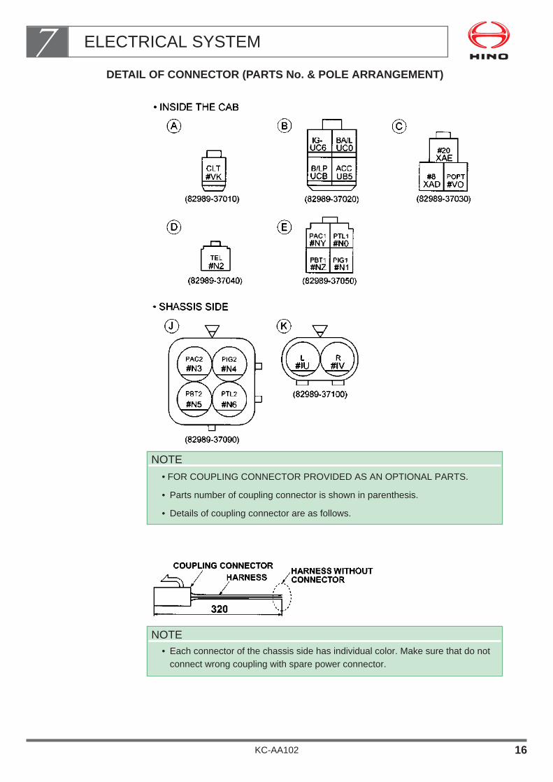
DETAIL OF CONNECTOR (PARTS No. & POLE ARRANGEMENT)
NOTE• Each connector of the chassis side has individual color. Make sure that do not
connect wrong coupling with spare power connector.
NOTE
• FOR COUPLING CONNECTOR PROVIDED AS AN OPTIONAL PARTS.
• Parts number of coupling connector is shown in parenthesis.
• Details of coupling connector are as follows.
ELECTRICAL SYSTEM7
KC-AA102 16

SPECIFICATIONS OF SPARE POWER CIRCUIT AND APPLICABLE CAPACITY
ELECTRICAL SYSTEM7
KC-AA102 17

NOTEThe permissible current to be taken from spare power connector is determined from thecapacity of the fuse and wire size.Make sure that the maximum load (current) of the installed equipment must be kept lowercurrent than the permissible capacity to be able to take from spare power connector.
Be sure to keep the lower current value than the alternator generated capacity whenswitched on the original and additional equipment same time to avoid over discharging elec-tricity of the battery.
Maximum capacity (current) of the each poles marked is 0.1~0.2A for taking signal circuitof the instrument.Be sure to use the this circuit to operate the relay for additional equipment of the body.Relay must be use the built-in surge absorbing diode type as Hino spare parts No.90987-02017 or equivalent.
Using length show the wire length from fuse to each connector (pole) of the spare outlet.Be sure to make circuit using the appropriate kind, size and length of the wire followed bythe table described in item "13. ELECTRIC WIRE SIZE AND PERMISSIBLE CURRENTS".
Parts number described in the connector drawing and the table will be changed withoutprior notice and obligation.Therefore, you should order the spare parts of coupling connector after confirming the cor-rect parts number with authorized Hino distributor or sales dealer.
ELECTRICAL SYSTEM7
KC-AA102 18

Instrument panel construction
(EXAMPLE DRAWING OF DISMOUNTING)
When dismount the instrument panel in order to install a relay, fuse or taking out thepower from spare power connector for the body mounting, carry out as following procedure.
ELECTRICAL SYSTEM7
KC-AA102 19

The center cluster panel and fuse lid can be dismounting to pull this side. When dis-mounting the glove box, pull this side after removing the tapping screws of upper 3 nos.and lower 2 nos.
NOTE• Should more detailed data or information with regard to dismounting
the instrument panel be needed, please contact authorized Hinodistributor or sales dealer.
ELECTRICAL SYSTEM7
KC-AA102 20
6. INSTALLATION OF ADDITIONAL EQUIPMENT AND SWITCHES
Layout of Equipment and Switches
Installing space of additional equipment• Have been provided the installing space (H:150mm x W:180 mm ) at the center cluster
which can be installed three kind of additional equipment as a wireless radio, electricalequipment and etc.
Layout of switches and lamps• Standard layout of switches and lamps are as following
figure. (Layout details of each model, see the Body Mounting Manual for the respectivemodel series.)
• If you intend to install additional switches or lamps at instrument panel for the conve-nience of body mounting, be sure to install it at empty space after confirmation of origi-nal condition of the actual vehicle.
• If you install additional switches and lamps, fit a caution plate showing the purpose ofeach switch, etc., to prevent accidental operation or confirmation.
Avoid using additional switches and lamps with existing switches and lamps.
ELECTRICAL SYSTEM7
KC-AA102 21
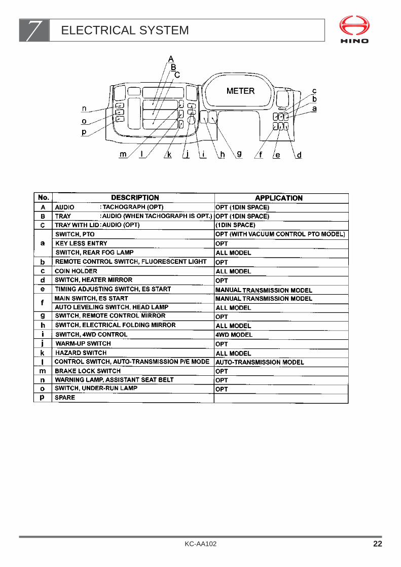
ELECTRICAL SYSTEM7
KC-AA102 22

Additional Switches• If you intend to install the switch to the instrument panel, use the switch mentioned
hereinafter which is provided as a spare parts.
ELECTRICAL SYSTEM7
KC-AA102 23

7. ADDITIONAL LAMPS
• The lamps properly installed to the vehicle has already been complied with the laws orregulations. Alteration and modification are therefore strictly prohibited.
• If you must install additional lamps, be sure to observe the following precautions.
• Moreover, installation of the additional lamps must be complied with the laws or regula-tions and install the harness to be observed the precautions of item"11. HARNESS WIRING".
• More detailed instructions of each model with regard to add the lamps, see the BodyMounting Manual for the respective model series.
Addition the Tail LampsTake the power from spare power connector for additional lamp as following figure. (Seenext page.)
Spare power connector is located at the left side No.3 crossmember (Pole code: J).
Additional lamp must be kept maximum 10 W per side.
After installation, make sure that the lamps operate properly or not.
Addition the Stop LampsMake the circuit to be added additional relay as following figure. (See next page.)
Additional stop lamps must be kept maximum 25 W and one piece per side.
After installation, make sure that the lamps operate properly or not.
ELECTRICAL SYSTEM7
KC-AA102 24
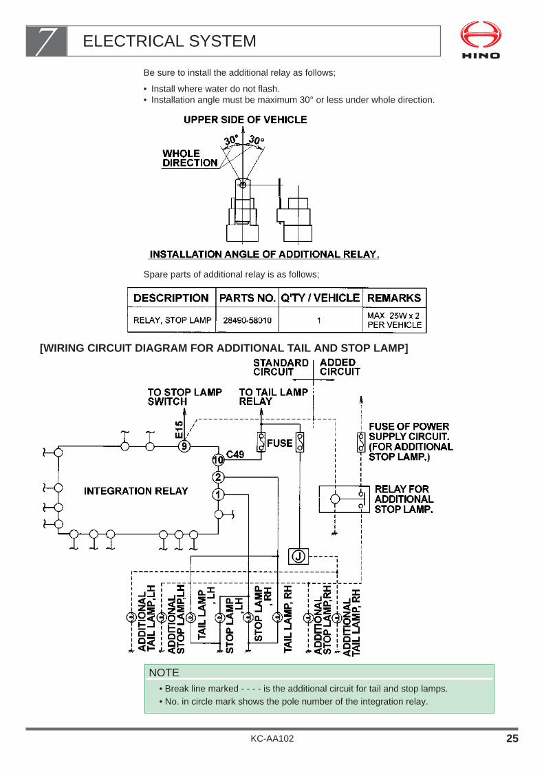
Be sure to install the additional relay as follows;
• Install where water do not flash.• Installation angle must be maximum 30° or less under whole direction.
Spare parts of additional relay is as follows;
[WIRING CIRCUIT DIAGRAM FOR ADDITIONAL TAIL AND STOP LAMP]
NOTE• Break line marked - - - - is the additional circuit for tail and stop lamps.• No. in circle mark shows the pole number of the integration relay.
ELECTRICAL SYSTEM7
KC-AA102 25

Addition the Directional Indicator Lamps (Hazard Warning Lamps)
Take power from power supply connector which is provided existing directional indicatorcircuit as following figure.
Power supply terminal is provided at the left behind No.3 crossmember (Pole No. K).
Additional directional indicator lamp must be kept maximum 25W and one piece per side.
After installation, make sure that the lamps operate properly or not.
Moreover, if additional directional indicator lamps have been installed, open circuit detec-tor system of the it’s circuit may become not to operate properly.
NOTE
• Break line marked - - - - is the additional circuit for directional indicator
lamps.
ELECTRICAL SYSTEM7
KC-AA102 26

8. DRAWING IN THE WIRE HARNESS INTO THE CAB
Penetration Hole of Wire Harness• The penetration hole to draw the wire harness into the cab is provided at the floor of
cab as following figure.
• When draw the wire harness, replace the grommet and draw it into the cab.
Make sure that the management should be taken such as disposing the sharp edge ofthe penetration hole and fixing the corrugated tube on the harness to prevent damage tothe wire and potential short circuit.
Make sure that the clearance between wire and penetration hole should be properlysealed by sealant to prevent water coming in and abnormal noise.
The penetration holes of wire marked A, B, C may be not able to use according to thevehicle’s specification.
Be sure to confirm the actual vehicle before drawing the harness (wire) and using emptyhole.
Using the chassis harness grommet together for drawing the additional wire is strictlyprohibited to prevent damage of chassis harness when processing the grommet.
Drawing as mentioned above shows as example.
More details of penetration hole and how to draw the wire harness of the each vehiclesee the Body Mounting Manual for the respective model series.
ELECTRICAL SYSTEM7
KC-AA102 27

9. POINTS TO NOTE ON ELECTRICAL WELDING
Electrical components such as the alternator and tachograph are directly connected tothe battery and one end is grounded to the chassis frame. Under these conditions, weld-ing current will flow back along the ground circuit if electric welding is carried out anddamage may be caused to the alternator, tachograph, electrical components, etc.
Always take the following precautions during welding.
Procedure before WeldingTurn the starter switch off.
Disconnect the battery’s negative terminal.
Disconnect the connector of ECU of the each electronic instrument.
NOTE
• Drawing as mentioned above shows as example.
• For details of installation position of ECU of the each vehicle, see the
Body Mounting Manual for the respective model series.
ELECTRICAL SYSTEM7
KC-AA102 28
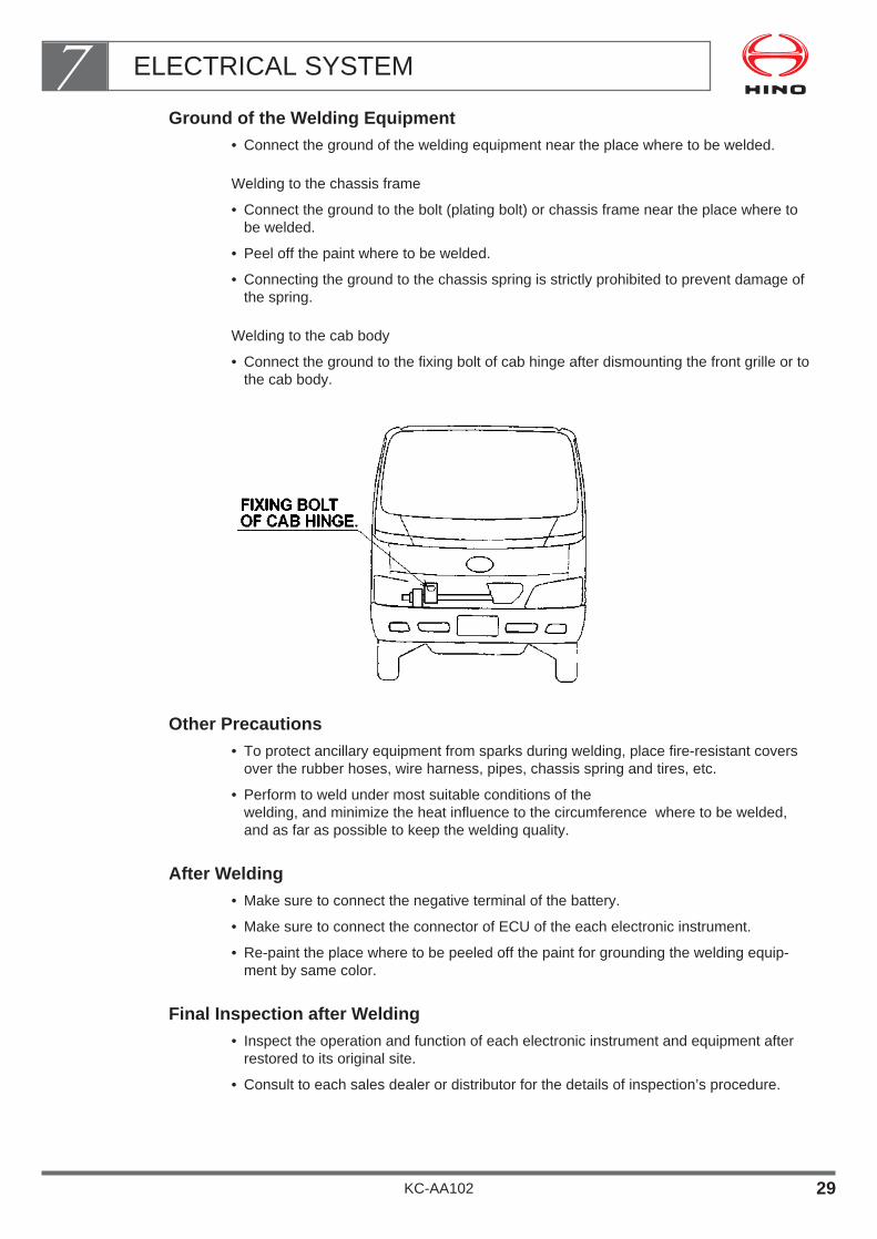
Ground of the Welding Equipment• Connect the ground of the welding equipment near the place where to be welded.
Welding to the chassis frame
• Connect the ground to the bolt (plating bolt) or chassis frame near the place where tobe welded.
• Peel off the paint where to be welded.
• Connecting the ground to the chassis spring is strictly prohibited to prevent damage ofthe spring.
Welding to the cab body
• Connect the ground to the fixing bolt of cab hinge after dismounting the front grille or tothe cab body.
Other Precautions• To protect ancillary equipment from sparks during welding, place fire-resistant covers
over the rubber hoses, wire harness, pipes, chassis spring and tires, etc.
• Perform to weld under most suitable conditions of the welding, and minimize the heat influence to the circumference where to be welded,and as far as possible to keep the welding quality.
After Welding• Make sure to connect the negative terminal of the battery.
• Make sure to connect the connector of ECU of the each electronic instrument.
• Re-paint the place where to be peeled off the paint for grounding the welding equip-ment by same color.
Final Inspection after Welding• Inspect the operation and function of each electronic instrument and equipment after
restored to its original site.
• Consult to each sales dealer or distributor for the details of inspection’s procedure.
ELECTRICAL SYSTEM7
KC-AA102 29
10. POINTS TO NOTE FOR ELECTRONIC MACHINES
• Due to recent improvements in vehicle performance and to comply with laws and regu-lations, vehicles are also being equipped with electronic computers.
• If this electronic equipment is subject to heat, shocks, or other factors such as highvoltage electrical welding, internal damage will occur and the equipment will stop func-tioning
• Accordingly, be sure to carefully observe the following precautions when mounting abody or equipment on a chassis in which electronic equipment is installed.
Kinds of Electronic Equipment• The electronic equipment used in HINO chassis are shown below.
HINO TE-system
• Electronic control governor
• Electronic control timer
• Pre-lift control fuel injection pump
A.B.S. (anti-lock brake system)
A.S.R. (anti-slip regulation system)
FSV controller
Vehicle speed control limiter
Auto-transmission control computer
Exhaust retarder control computer, etc.
Handling Precautions• Circuits related to electronic control (control unit, actuator, sensor, etc.) use a special
multi-terminal connector because they use a very small current.
Therefore, take note of the following points when handling them white mounting thebody.
Unnecessary removal or insertion of connectors should not be done.
Deformation or damage to connectors will result in decreases in the insertion forceand poor connections.
When removing the connector, be sure to hold the male and female parts of the con-nector housing.
Removing the connector by holding the harness wire and pulling or twisting will cause damage to the harness wire and deformation of theterminal. Do not remove the connector in this way.
Be sure water, oil, or dust do not adhere to the removed connector. Poor connectionsor unstable continuity will result.
When connecting the connector, be sure to securely connect it until the lock engages.
Observe the following precautions for electronic equipment installed on the body side.
• The electronic equipment may malfunction due to large amounts of noise generatedby the equipment itself.Accordingly, a component with a noise eliminator such as a diode of bakusutaattached should be used for the relay, solenoid, or motors installed to the body.
ELECTRICAL SYSTEM7
KC-AA102 30

Be sure to fix it back at existing position when harness clamps, etc. to be removed.
If shipping the vehicle must be done without battery cover because of body mounting,be sure to confirm the fitting of the positive terminal’s cover of battery.Fit the cover where it is not.
ELECTRICAL SYSTEM7
KC-AA102 31

11. HARNESS WIRING
• If a mistake is made in the harness wiring while mounting the body or equipment, theharness may be damaged by vehicle vibration while the vehicle is driving, or water,dust, or mud entering into the harness. If these occur, a short-circuit or fire may result causing a severe accident.
• Accordingly, be sure to observe the procedures given below for modifications or alter-ations of the harness wiring involved with the body mounting or other actions.
Precautions when Mounting Body or Equipment
When installing U-bolts or body mounting brackets, observe the following precautions.
• Make sure that harness wires and battery cables are not squeezed or pinched, anddo not come into contact with sharp edges or corners.
• Make sure that harness wires, battery cables and other electric equipment (switches,battery, etc.) are easily accessible for maintenance.
If you fit additional switches or lamps for a body or equipment, observe the following pre-cautions.
• To prevent accidental operation or confirmation, install a caution plate showing thepurpose of each switch, etc.
ELECTRICAL SYSTEM7
KC-AA102 32

• Common use of switches which are already installed on the chassis side for control oflamps installed on the body side or other electrical equipment is prohibited.
An overload will occur resulting in burning of the switch contacts or harness.
The control of the electrical equipment on the body side should be done using a sepa-rately installed switch.
If you intended to fit a buzzer for a body or equipment, make sure that its sound is clearlydifferent from that of the existing buzzer around the driver’s seat of chassis.
[SPECIFICATION OF EXISTING BUZZER AROUND DRIVER’S SEAT]
Do not force to pull the harness wiring when handle it.
When removing the connector, be sure to hold the male and female parts of the connec-tor by housing.
Do not remove the connector by holding harness wire.
ELECTRICAL SYSTEM7
KC-AA102 33
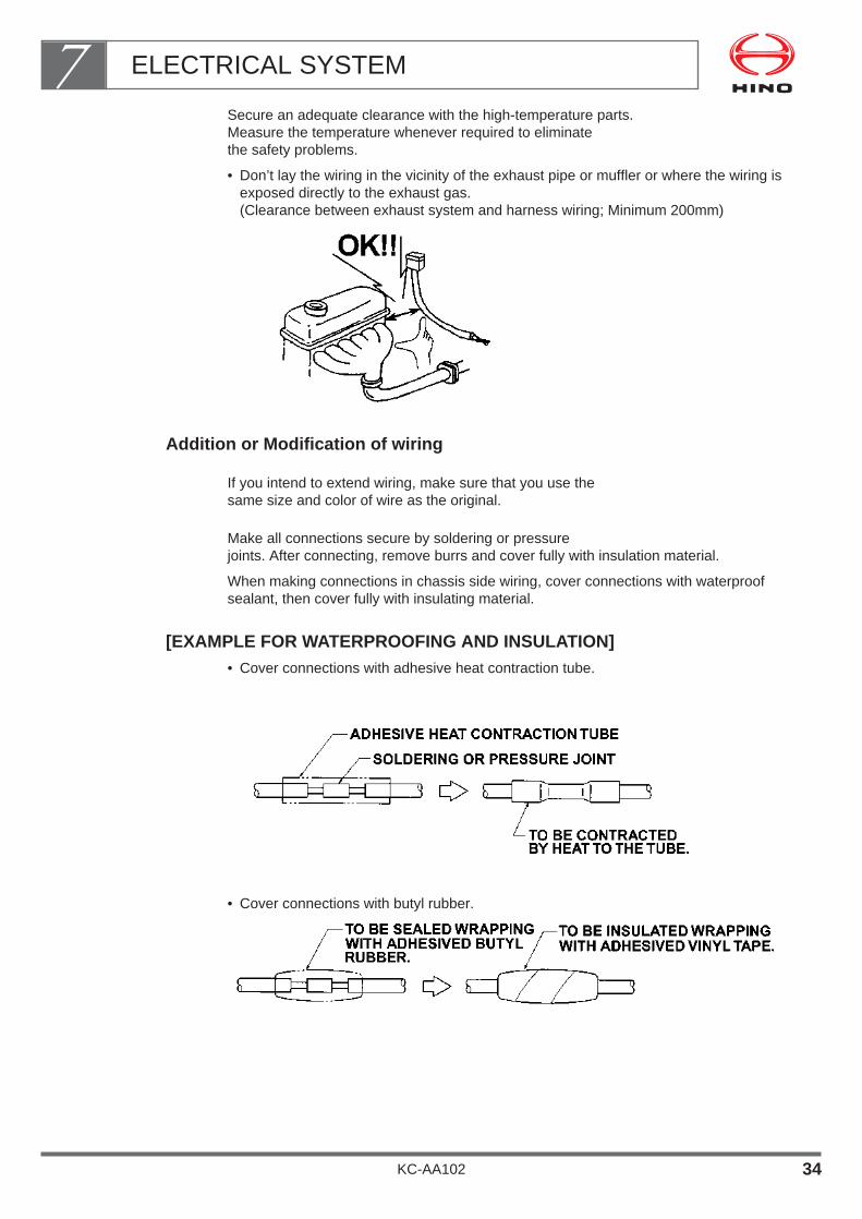
Secure an adequate clearance with the high-temperature parts.Measure the temperature whenever required to eliminate the safety problems.
• Don’t lay the wiring in the vicinity of the exhaust pipe or muffler or where the wiring isexposed directly to the exhaust gas.(Clearance between exhaust system and harness wiring; Minimum 200mm)
Addition or Modification of wiring
If you intend to extend wiring, make sure that you use the same size and color of wire as the original.
Make all connections secure by soldering or pressure joints. After connecting, remove burrs and cover fully with insulation material.
When making connections in chassis side wiring, cover connections with waterproofsealant, then cover fully with insulating material.
[EXAMPLE FOR WATERPROOFING AND INSULATION]• Cover connections with adhesive heat contraction tube.
• Cover connections with butyl rubber.
ELECTRICAL SYSTEM7
KC-AA102 34
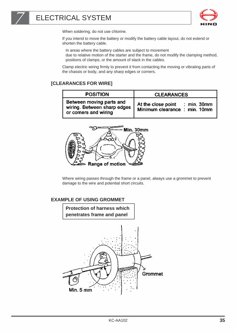
When soldering, do not use chlorine.
If you intend to move the battery or modify the battery cable layout, do not extend orshorten the battery cable.
In areas where the battery cables are subject to movement due to relative motion of the starter and the frame, do not modify the clamping method,positions of clamps, or the amount of slack in the cables.
Clamp electric wiring firmly to prevent it from contacting the moving or vibrating parts ofthe chassis or body, and any sharp edges or corners.
[CLEARANCES FOR WIRE]
Where wiring passes through the frame or a panel, always use a grommet to preventdamage to the wire and potential short circuits.
EXAMPLE OF USING GROMMET
Protection of harness whichpenetrates frame and panel
ELECTRICAL SYSTEM7
KC-AA102 35

Do not install wiring where it may be damaged by accumulation of mud or snow, by freezing, or by flying stones.
If you must install wiring in such positions, protect it with metal plates.
When wiring of the harness wire is done inside the chassis frame, place the wiring alongalready installed wiring and do not wire independently along empty spaces.
Also, when wiring under the floor of the body or inside the roof construction, be sure toplace the wiring along the structure frame, use a clip following the indicated interval,carry out water proofing measures and observe the harness wiring rules.
Do not make connections by cutting open the coating of a wire and pulling out the barewire. This procedure is very dangerous and may damage other wires.
To prevent water from running along wires and penetrating electrical equipment, alwaysseal holes through which wires pass using grommets and make connections so that theterminal is higher than the wire.
ELECTRICAL SYSTEM7
KC-AA102 36
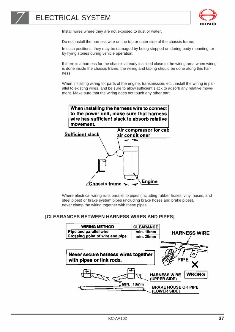
Install wires where they are not exposed to dust or water.
Do not install the harness wire on the top or outer side of the chassis frame.
In such positions, they may be damaged by being stepped on during body mounting, orby flying stones during vehicle operation.
If there is a harness for the chassis already installed close to the wiring area when wiringis done inside the chassis frame, the wiring and taping should be done along this har-ness.
When installing wiring for parts of the engine, transmission, etc., install the wiring in par-allel to existing wires, and be sure to allow sufficient slack to adsorb any relative move-ment. Make sure that the wiring does not touch any other part.
Where electrical wiring runs parallel to pipes (including rubber hoses, vinyl hoses, andsteel pipes) or brake system pipes (including brake hoses and brake pipes), never clamp the wiring together with these pipes.
[CLEARANCES BETWEEN HARNESS WIRES AND PIPES]
ELECTRICAL SYSTEM7
KC-AA102 37

If you move the battery, you may have to temporarily remove the battery cables from theterminals of the battery.
When refitting the battery cables, observe the specified torque to avoid damaging thebattery terminal:
Tightening torque : 9.8~15.7 N•m {100~160 kgf•cm}
(If a terminal is damaged, replace it with a new part.)
If you move the battery, make sure it is positioned at least 200 mm away from theexhaust system (muffler, tail pipe, etc.).
If you must install the battery within 200 mm of the exhaust system, protect it with insulat-ing panels.
Always use a connector with lock.
If you use a plug-type connecting terminal, fit the female terminal into the power supplyside.
This is due to the connecting terminal detaching which does not allow a short-circuit tooccur even if the chassis or body construction make contact.
To prevent sagging, contact with other parts or contact with sharp edges or corners,secure all wiring with clips.
The clips should be spaced at a standard interval of 300~500 mm. This interval shouldbe shorter where conditions dictate.
ELECTRICAL SYSTEM7
KC-AA102 38

All clips should use resin coating or attached grommets.
[RECOMMENDED CLIP TYPES]
Crocodile clips and adhesive clips should only be used for temporary installation.
Harness wires should be installed above fuel hoses or pipes to avoid fuel dripping ontothe harness wire in the event that a fuel leak occurs.
Keep a clearance of at least 20 mm between the harness wire and fuel hose.
Bundle unused harness wires and their terminals should be bundled with other harnesswires and covered with vinyl tape to prevent water from penetrating the terminal.
ELECTRICAL SYSTEM7
KC-AA102 39

Mount a cover or a protector to prevent water entry along the wiring.
• A water-proof boot should be installed facing down.
A connector, if used at a position exposed to water, should always be of water-prooftype.
The circuit must be so designed that the ground cable of the additional power supply isconnected to the negative “–” terminal of the battery.
Install the ground for an additional power supply always on the engine or frame.
Mount the ground terminal securely in the from of a circular plate terminal.
Fuses of optimum capacity must be used for vehicles considering the operating load andthe operating frequency.
Don’t add any load from accessories to the existing fuses.
Always be sure to insert a fuse in an added wiring circuit.
Use a vinyl-coated clamp, taking adequate care against short circuit.
ELECTRICAL SYSTEM7
KC-AA102 40
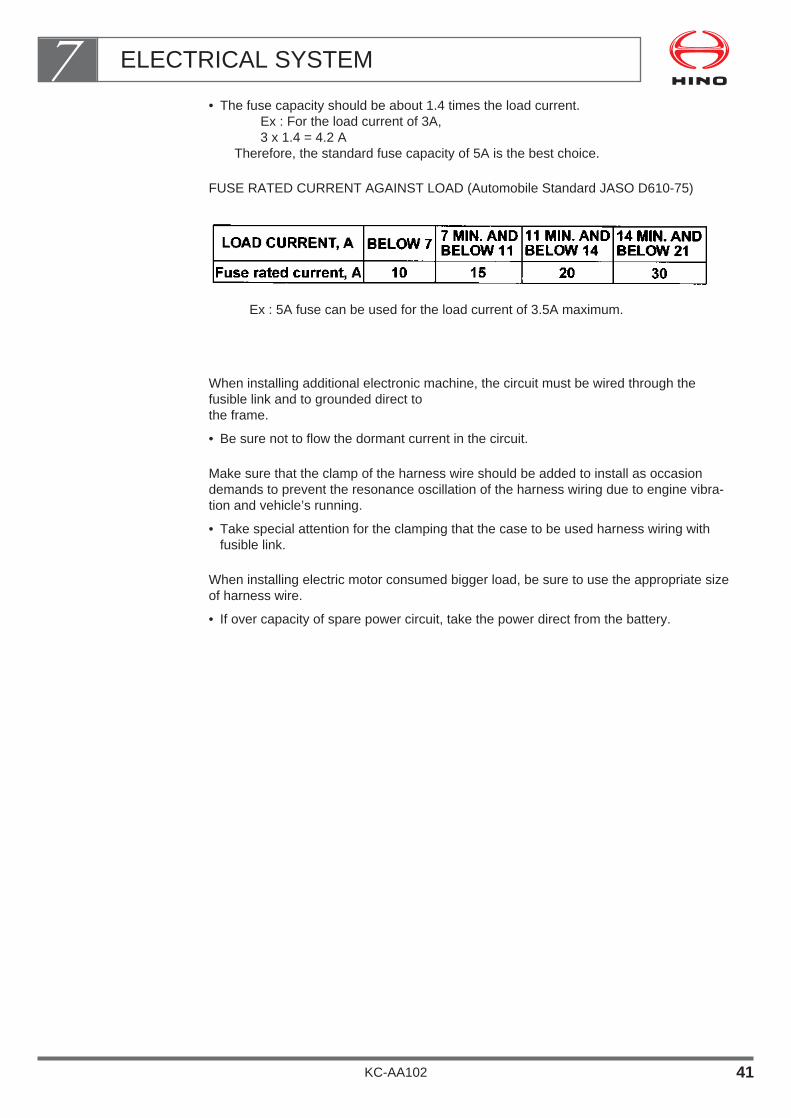
• The fuse capacity should be about 1.4 times the load current.Ex : For the load current of 3A,3 x 1.4 = 4.2 A
Therefore, the standard fuse capacity of 5A is the best choice.
FUSE RATED CURRENT AGAINST LOAD (Automobile Standard JASO D610-75)
Ex : 5A fuse can be used for the load current of 3.5A maximum.
When installing additional electronic machine, the circuit must be wired through thefusible link and to grounded direct to the frame.
• Be sure not to flow the dormant current in the circuit.
Make sure that the clamp of the harness wire should be added to install as occasiondemands to prevent the resonance oscillation of the harness wiring due to engine vibra-tion and vehicle’s running.
• Take special attention for the clamping that the case to be used harness wiring withfusible link.
When installing electric motor consumed bigger load, be sure to use the appropriate sizeof harness wire.
• If over capacity of spare power circuit, take the power direct from the battery.
ELECTRICAL SYSTEM7
KC-AA102 41
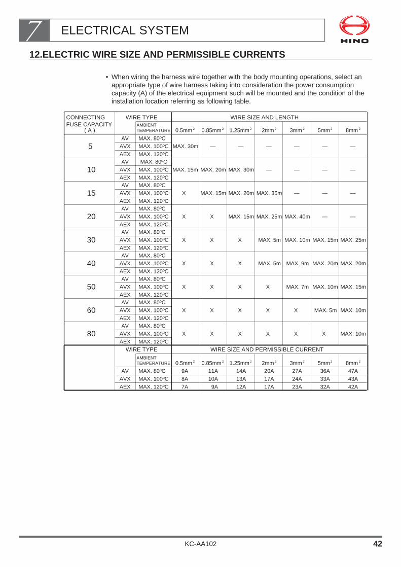
12.ELECTRIC WIRE SIZE AND PERMISSIBLE CURRENTS
• When wiring the harness wire together with the body mounting operations, select anappropriate type of wire harness taking into consideration the power consumptioncapacity (A) of the electrical equipment such will be mounted and the condition of theinstallation location referring as following table.
WIRE TYPE
WIRE TYPE
WIRE SIZE AND LENGTH
WIRE SIZE AND PERMISSIBLE CURRENT
( A )
CONNECTINGFUSE CAPACITY AMBIENT
TEMPERATURE 0.5mm 0.85mm 1.25mm 2mm 3mm 5mm 8mm
AV MAX. 80ºC
MAX. 80ºC
MAX. 80ºC
MAX. 80ºC
MAX. 80ºC
MAX. 80ºC
MAX. 80ºC
MAX. 80ºC
MAX. 80ºC
MAX. 80ºC
5 AVX MAX. 100ºC
MAX. 100ºC
MAX. 100ºC
MAX. 100ºC
MAX. 100ºC
MAX. 100ºC
MAX. 100ºC
MAX. 100ºC
MAX. 100ºC
MAX. 100ºC
MAX. 30m — — — — — —AEX MAX. 120ºC
MAX. 120ºC
MAX. 120ºC
MAX. 120ºC
MAX. 120ºC
MAX. 120ºC
MAX. 120ºC
MAX. 120ºC
MAX. 120ºC
MAX. 120ºC
AV
10 AVX MAX. 15m MAX. 20m MAX. 30m — — — —AEXAV
15 AVX X MAX. 15m MAX. 20m MAX. 35m — — —AEXAV
20 AVX X X MAX. 15m MAX. 25m MAX. 40m — —AEXAV
30 AVX X X X MAX. 5m MAX. 10m MAX. 15m MAX. 25mAEXAV
40 AVX X X X MAX. 5m MAX. 9m MAX. 20m MAX. 20mAEXAV
50 AVX X X X X MAX. 7m MAX. 10m MAX. 15mAEXAV
60 AVX X X X X X MAX. 5m MAX. 10mAEXAV
80 AVX X X X X X X MAX. 10mAEX
AV 9A 11A 14A 20A 27A 36A 47AAVX 8A 10A 13A 17A 24A 33A 43AAEX 7A 9A 12A 17A 23A 32A 42A
2 2 2 2 2 2 2
AMBIENTTEMPERATURE 0.5mm 0.85mm 1.25mm 2mm 3mm 5mm 8mm2 2 2 2 2 2 2
ELECTRICAL SYSTEM7
KC-AA102 42
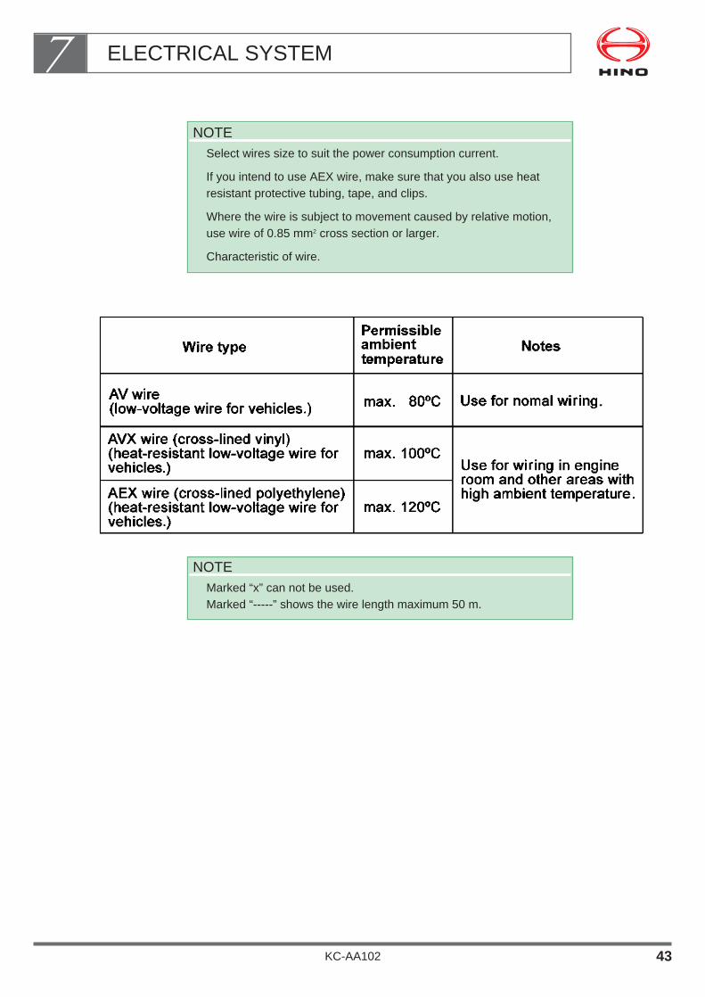
NOTEMarked “x” can not be used.Marked “-----” shows the wire length maximum 50 m.
NOTESelect wires size to suit the power consumption current.
If you intend to use AEX wire, make sure that you also use heatresistant protective tubing, tape, and clips.
Where the wire is subject to movement caused by relative motion,use wire of 0.85 mm2 cross section or larger.
Characteristic of wire.
ELECTRICAL SYSTEM7
KC-AA102 43

13. ELECTRICAL WIRING DIAGRAM
The diagrams as mentioned herein after are for examples.
Therefore, you are kindly requested to refer to the workshop manual, owner's manual,etc. for the electrical wiring diagram.
How to use and read the electrical wiring diagram is described as follows.
Configuration of Electrical Wiring Diagram
Electrical wiring diagrams are described in the following classifications.• How to read the wiring diagram for individual system.
Several kinds of circuits are described as individual groups and are explained for con-nectors of related parts, wire sizes, colors of the wires, etc.
• Wiring diagram for individual system.
Mainly those circuits that are connected with the body mounting are described as indi-vidual groups and are explained for connectors of related parts, wire sizes, colors ofthe wires, etc.
• Block configuration diagram.
Shows configuration such as FL(fusible link), F/B(fuse box), etc.
How to Read the Wiring Diagram for Individual System.
As circuit diagram mentioned on this wiring diagram includes special specifications, some of them are not applicable depending upon vehiclemodel and specification.
For detailed specifications of the individual model, contact with your nearest HINO salesdealer or distributor.
Symbols, terms and abbreviations.
Explanation of symbols
ELECTRICAL SYSTEM7
KC-AA102 44

ELECTRICAL SYSTEM7
KC-AA102 45
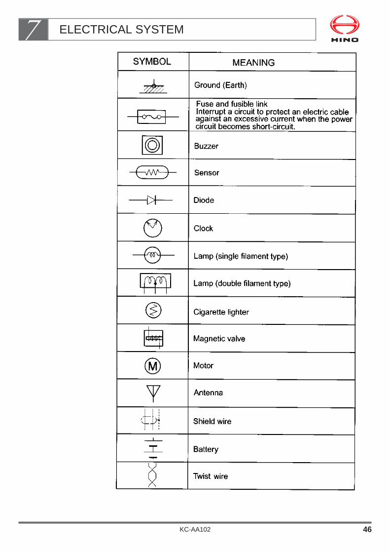
ELECTRICAL SYSTEM7
KC-AA102 46

Explanation of terms
Explanation of abbreviations
ELECTRICAL SYSTEM7
KC-AA102 47

KC-AA102 48
ELECTRICAL SYSTEM7How to read circuit diagram

KC-AA102 49
ELECTRICAL SYSTEM7How to read connector for each parts
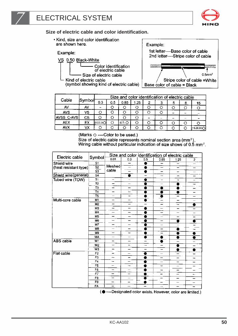
Size of electric cable and color identification.
ELECTRICAL SYSTEM7
KC-AA102 50
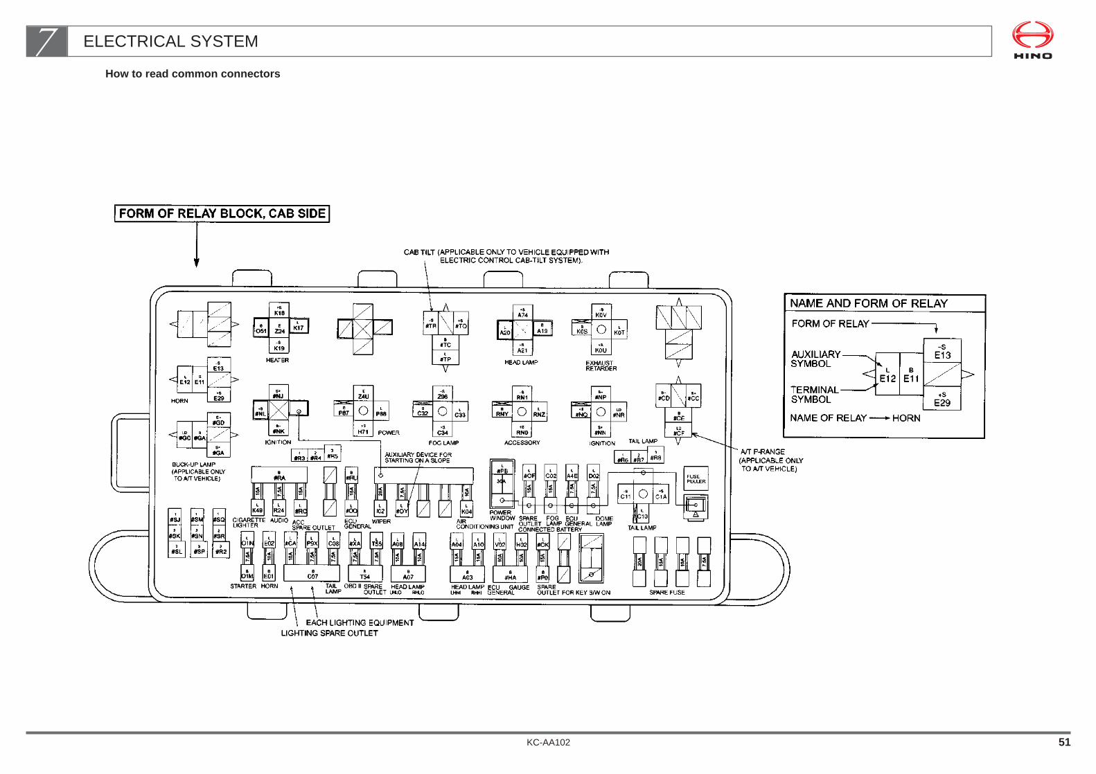
KC-AA102 51
ELECTRICAL SYSTEM7How to read common connectors

KC-AA102 52
ELECTRICAL SYSTEM7
L
#ORL
O0T
L
#OGL
#OC
+S
#Q0-S
#Q1
B#Q3
L
#Q2A
BS
1
40A
HT
R
40A
E-F
AN
30A
MA
IN4
30A
ALT
80A (FOR 30A AND 50A ALTERNATOR)
FORM OF RELAY BLOCK, CHASSIS SIDE
FAN RELAY, AIR CONDITIONER
MA
IN2
60A
MA
IN3
60A
AM
1
30A
HE
AD
50A
L
#IL
OP
T
50A
GLO
W
(EXCEPT J05C ENGINE)
(ENGINE MODEL : S05C,S05D,4B)
(ENGINE MODEL : S05C,S05D,15B-FTE)
(ENGINE MODEL : S05C,S05D,15B-FTE)
(4B ENGINE ONLY)
PW
R
L
X36ECU
XD0
-S
Z23B
X35
ECD RELAY
L
Y95IG
Y96
P+Y97
+BY94
FUEL HEATER
SPVJ5M
B2
J5NS-
#BD
B
J5L
LKSK
+S
KSL-S
KSM
B
KSJ
BM
W1W
+BM
WAH
SRW2A
R+WLR
ABS MTR MAIN RELAY
SPILL VALVE RELAY
REAR HEATER RELAY
CAB TILT RELAY
+S
K3F-S
K88
BO76
L
K14
DEFROSTER RELAY
R+
WJQ
MR
W2B
BS
W1X+BS
WAJ
ABS SOLENOID MAIN RELAY
S+
#NA
S-
#NB
L
#IPL
J02
LD
#ND+B
#NC
IGNITION RELAY
L
O0SL
O0RL
E04L
N1A
7.5A
L
K48
15A
20A
7.5A
15A
ALTERNATORAM2
STOP LAMPIGNITION
DEFROSTER
L
#YQL
X04L
F0H
20A
15A
10A
FUELHEATER
ENGINE HAZARD
L
#IT
L
#WIL
K5BL
#LXL
#JX
RR
HT
R
30A
L
#KA
B
#IS20A
ABS SOLENOIDSTARTER RELAY
GLOW MAIN RELAY
ENGINE MODEL : S05C,S05D,J05C
STARTER RELAY
GLOW MAIN RELAY
ENGINE MODEL : 4B
STARTER RELAY
GLOW MAIN RELAY
ENGINE MODEL : 15B-FTE
LO45
BO0M
+S
K7C-S
K7D
L
K7E
B
K7B
COMPRESSOR
+S
K96-S
KAS
L
K97
B
K94
BLOWER FANLow
+S
K61-S
K65
L
K6Z
B
K6U
BLOWER FANHi

EXHAUST SYSTEM
1. PRECAUTIONS FOR MOUNTING A BODY OR EQUIPMENT ・・・・・・・・・・・・・・・・・・・・・・・・・・・・・・・・・・・・ 2
2. MODIFYING THE EXHAUST SYSTEM ・・・・・・・・・・・・・・ 4
KC-AA102
Chapter 8

• The exhaust system becomes very hot during driving.When mounting a body or equipment, observe the following proce-dures to prevent vehicle fires.
• Modifying the exhaust system has a major effect on vehicle perfor-mance and external noise.As a rule, the exhaust system must not be modified.
• In some countries, external noise control regulations prohibit anymodification of the exhaust system.
EXHAUST TAIL PIPE
MUFFLER
EXHAUST SYSTEM
ENGINE
EXHAUST PIPE
EXHAUST MANIFOLD
EXHAUST SYSTEM8
KC-AA102 1
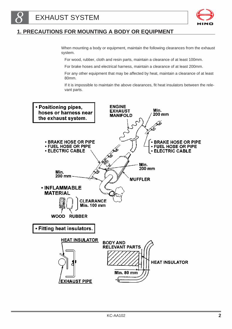
1. PRECAUTIONS FOR MOUNTING A BODY OR EQUIPMENT
When mounting a body or equipment, maintain the following clearances from the exhaustsystem.
For wood, rubber, cloth and resin parts, maintain a clearance of at least 100mm.
For brake hoses and electrical harness, maintain a clearance of at least 200mm.
For any other equipment that may be affected by heat, maintain a clearance of at least80mm.
If it is impossible to maintain the above clearances, fit heat insulators between the rele-vant parts.
EXHAUST SYSTEM8
KC-AA102 2
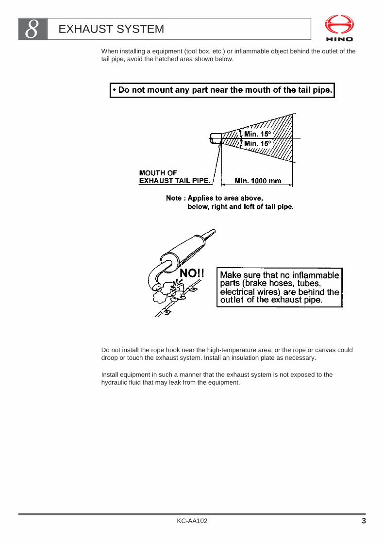
When installing a equipment (tool box, etc.) or inflammable object behind the outlet of thetail pipe, avoid the hatched area shown below.
Do not install the rope hook near the high-temperature area, or the rope or canvas coulddroop or touch the exhaust system. Install an insulation plate as necessary.
Install equipment in such a manner that the exhaust system is not exposed to thehydraulic fluid that may leak from the equipment.
EXHAUST SYSTEM8
KC-AA102 3

2. MODIFYING THE EXHAUST SYSTEM
Modifying the exhaust system has a major effect on vehicle performance and externalnoise. As a rule, the exhaust system must not be modified.
In some countries, external noise control regulations prohibit any modification of theexhaust system.
Do not modify any part within the range shown in the drawing below.
If you must modify the tail pipe in order to install a fire arrester, observe the following pro-cedure:
The diameter and material of the pipe must be the same as those of the vehicle’s originalpipe. The material used differ as follows;
•Aluminum-plated steel pipe Color: Silver
The plating of aluminum-plated pipe will peel if the pipe is welded, and the rust-resis-tance of the pipe will deteriorate. After welding, paint the pipe in a similar color.
Extending or bending the tail pipe raises the exhaust resistance and will lead to a declinein engine output, an increase in fuel consumption, and an increase in exhaust gas densi-ty. Study the likely effects with care before making any modification of this kind. As arule, the bending radius of the tail pipe should be at least 1.5 times the diameter of thepipe.
EXHAUST TAIL PIPEMUFFLEREXHAUST PIPE
Do not modify any part of exhaustsystem within this range.
EXHAUST SYSTEM8
KC-AA102 4
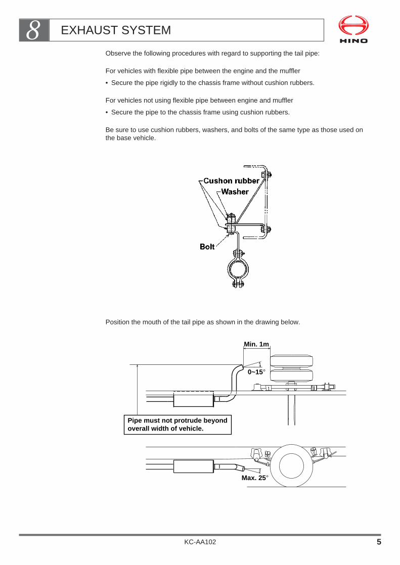
Observe the following procedures with regard to supporting the tail pipe:
For vehicles with flexible pipe between the engine and the muffler
• Secure the pipe rigidly to the chassis frame without cushion rubbers.
For vehicles not using flexible pipe between engine and muffler
• Secure the pipe to the chassis frame using cushion rubbers.
Be sure to use cushion rubbers, washers, and bolts of the same type as those used onthe base vehicle.
Position the mouth of the tail pipe as shown in the drawing below.
Min. 1m
0~15°
Max. 25°
Pipe must not protrude beyondoverall width of vehicle.
EXHAUST SYSTEM8
KC-AA102 5

Clearances between exhaust parts and other parts
The exhaust system becomes very hot during driving.Observe the following procedures to prevent vehicle fires.
Clearances from body parts
When mounting a body or equipment, observe the precautions given in this section.
Clearances from fuel system parts
Maintain a clearance of at least 200mm between the fuel tank, fuel pipes, etc. and thehot parts of the exhaust system.If you cannot maintain a clearance of 200mm, fit heat insulators to protect the fuel tankand fuel pipes.When arranging fuel piping, make sure that even if a fuel line ruptures and fuel leaks out,no fuel will come into contact with the hot parts of the exhaust system.
Never make joints in the fuel pipes above the hot parts of the exhaust system, etc.
When moving the fuel tank or installing an additional tank, make sure that the filling portis at least 300mm away from the mouth of the tail pipe and at least 200mm away fromexposed electrical terminals.
Clearances from other chassis parts
Maintain the clearances shown in the table below. If you cannot maintain these clear-ances, fit heat insulators.
EXHAUST SYSTEM8
KC-AA102 6

BATTERY
1. WIRING PRECAUTIONS ・・・・・・・・・・・・・・・・・・・・・・・・・・ 2
2. CHANGE OF BATTERY MOUNTING POSITION ・・・・・・ 3
3. NO OVERLAID CONNECTION OF BATTERY CABLE ・・・・・・・・・・・・・・・・・・・・・・・・・・・・・・・・・・・・・・・・ 3
4. REPLACEMENT BATTERY CABLE ・・・・・・・・・・・・・・・・ 3
5. SERVICEABILITY ・・・・・・・・・・・・・・・・・・・・・・・・・・・・・・・・ 4
KC-AA102
Chapter 9

• The battery is an item which, if handled inappropriately, may causea malfunction of the electrical components of the vehicle or anengine trouble or a fire.
Strictly observe the instructions on the battery and battery cable.
BATTERY
BATTERY9
KC-AA102 1
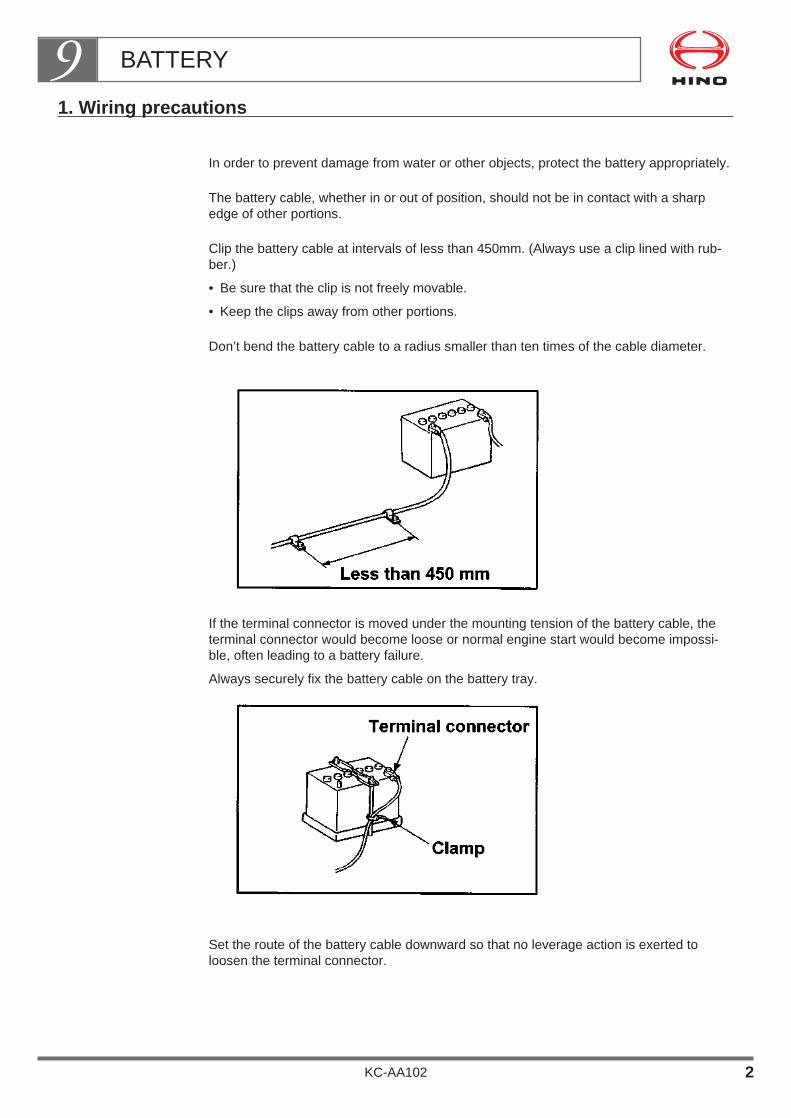
1. Wiring precautions
In order to prevent damage from water or other objects, protect the battery appropriately.
The battery cable, whether in or out of position, should not be in contact with a sharpedge of other portions.
Clip the battery cable at intervals of less than 450mm. (Always use a clip lined with rub-ber.)
• Be sure that the clip is not freely movable.
• Keep the clips away from other portions.
Don’t bend the battery cable to a radius smaller than ten times of the cable diameter.
If the terminal connector is moved under the mounting tension of the battery cable, theterminal connector would become loose or normal engine start would become impossi-ble, often leading to a battery failure.
Always securely fix the battery cable on the battery tray.
Set the route of the battery cable downward so that no leverage action is exerted toloosen the terminal connector.
BATTERY9
KC-AA102 2

2. CHANGE OF BATTERY MOUNTING POSITION
Install the battery at a position where the air flow is sufficient to release into the atmos-phere the gas generated during the temperature increase or the charging operation.
Keep the battery away from a heat source by 200mm minimum. When this distance isnot available, protect the battery from heat using a heat insulating plate or the like.
Determine the battery position using the existing battery cable
3. NO OVERLAID CONNECTION OF BATTERY CABLES
• Never connect battery cables by overlaying them one on another.
4. REPLACEMENT BATTERY CABLE
Replacing the battery cable may cause an engine start problem and causes the loss ofother key systems.
Comply with the following instructions strictly.
In order to secure the appropriate functions of the battery cable, use a cable with the fol-lowing specifications.
When a minus cable is installed on the frame as a result of battery relocation, connect acable of substantially the same size as the plus cable between the frame and the engineto cope with a large electric load of the starting circuit.
BATTERY9
KC-AA102 3

5. SERVICEABILITY
During the service or check work, secure a sufficient space or insulation in order not tocause any accident such as short circuit.
Attach a terminal polarity marking, a caution label and an gravity meter (mark) at an easi-ly visible position.
BATTERY9
KC-AA102 4

SUSPENSION AND TIRE
1. SUSPENSIONS USED IN THE CHASSIS ・・・・・・・・・・・・ 1
2. PROHIBITED MODIFICATION OR ALTERATION・・・・・・ 2
3. SERVICEABILITY ・・・・・・・・・・・・・・・・・・・・・・・・・・・・・・・・ 3
4. OTHER PRECAUTIONS WHEN MOUNTING OR MODIFICATION・・・・・・・・・・・・・・・・・・・・・・・・・・・・・・ 4
5. TIRE ・・・・・・・・・・・・・・・・・・・・・・・・・・・・・・・・・・・・・・・・・・・・ 6
KC-AA102
Chapter 10
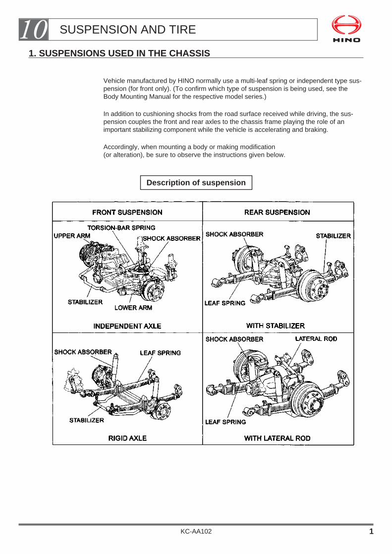
1. SUSPENSIONS USED IN THE CHASSIS
Vehicle manufactured by HINO normally use a multi-leaf spring or independent type sus-pension (for front only). (To confirm which type of suspension is being used, see theBody Mounting Manual for the respective model series.)
In addition to cushioning shocks from the road surface received while driving, the sus-pension couples the front and rear axles to the chassis frame playing the role of animportant stabilizing component while the vehicle is accelerating and braking.
Accordingly, when mounting a body or making modification(or alteration), be sure to observe the instructions given below.
Description of suspension
SUSPENSION AND TIRE10
KC-AA102 1
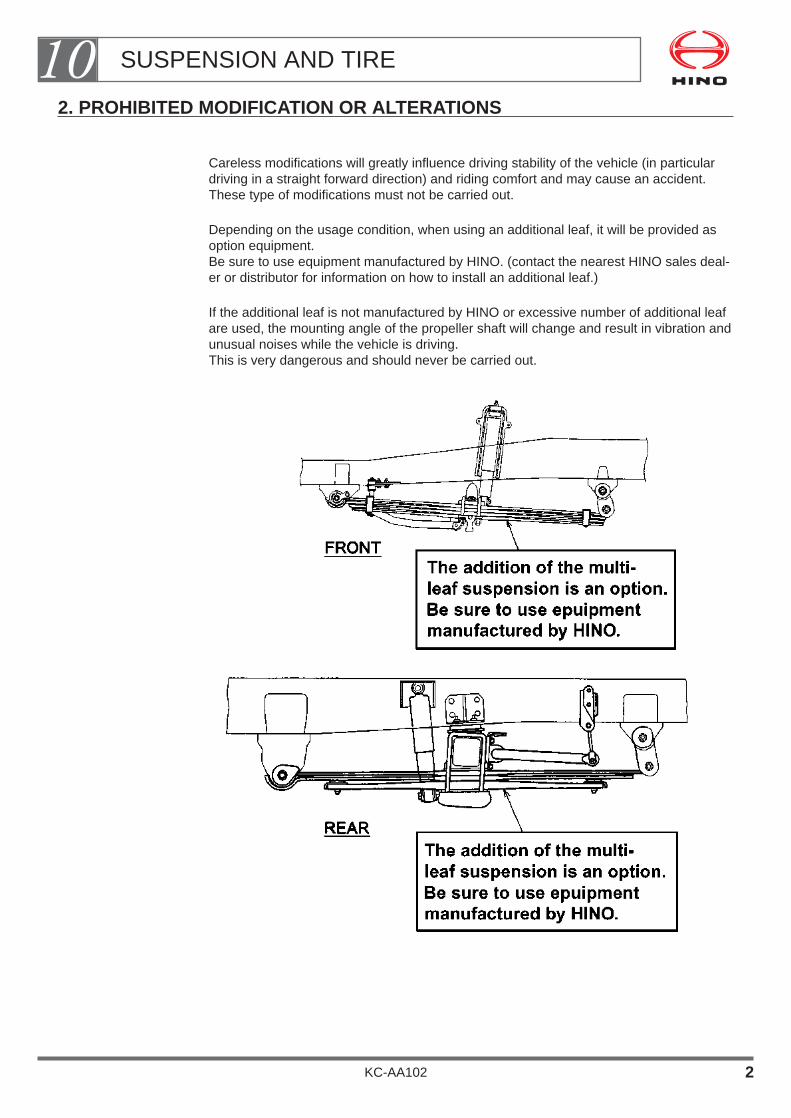
2. PROHIBITED MODIFICATION OR ALTERATIONS
Careless modifications will greatly influence driving stability of the vehicle (in particulardriving in a straight forward direction) and riding comfort and may cause an accident.These type of modifications must not be carried out.
Depending on the usage condition, when using an additional leaf, it will be provided asoption equipment.Be sure to use equipment manufactured by HINO. (contact the nearest HINO sales deal-er or distributor for information on how to install an additional leaf.)
If the additional leaf is not manufactured by HINO or excessive number of additional leafare used, the mounting angle of the propeller shaft will change and result in vibration andunusual noises while the vehicle is driving.This is very dangerous and should never be carried out.
SUSPENSION AND TIRE10
KC-AA102 2

3. SERVICEABILITY
The suspension is a component which is always moving while the vehicle is driving andas such requires periodic greasing and parts replacement in addition to daily mainte-nance and inspection.
Accordingly, to make these operations easier, consider a construction which allows sim-ple removal of the body parts of the peripheral assemblies as well as installing an inspec-tion cover.
NOTE• To make it possible to carry out inspections, maintenance and
repair or replace the parts inside the , an inspection cover shouldbe installed or the construction should be such to allow the bodyparts to be removed.
• The figure above shows a multi-leaf front suspension.The same procedures should be followed for the rear suspension.
SUSPENSION AND TIRE10
KC-AA102 3

4. OTHER PRECAUTIONS WHEN MOUNTING OR MODIFICATION
Suspension parts absorb shocks from the road surface received while driving and arealways changing shape.
Accordingly, the parts are manufactured from very special metal materials or other mate-rials.
Accordingly, if subjected to the effects of heat or other environmental factors, this is dan-ger that the material hardness may easily drop or suffer damage.
Therefore, do not use electrical welding of the suspension parts or a gas torch to applyheat.
The ground used during electrical welding must not make connect with the suspensionparts.
During welding operations around the periphery of suspension parts, be sure to protectthe suspension parts using a cover or similar item so the parts are not subjected to weld-ing sparks.
SUSPENSION AND TIRE10
KC-AA102 4

Because in the peripheral portion of the bracket where the suspension parts are installedconstantly a large amount of stress is generated while the vehicle is driving, heat mustnot be applied to this portion by electrical welding or a gas torch.
NOTE• The figure above only shows a multi-leaf suspension. The same
precautions also apply to independent type front suspension aswell.
• Make alterations taking into consideration the upper bound limit ofthe differential carrier and the tire so that the tire does not interferewith the body, etc. when the vehicle bounds on rough roads.
For vehicles destined for districts where installation of the tire chainis required, add the tire chain clearance to the upper limit consider-ation. (For more details, refer to the Body Mounting Manual for therespective model series.)
• In the case where the vehicle is equipped with a rear axle breatherand a hose, take care not to bend, distort or enclose them or other-wise interfere with normal “breathing” of the rear axle.
• The leaf spring should be installed at a point distant from theexhaust pipe by 50mm minimum and from the muffler by 150mmminimum.
In the case where these distances cannot be secured, protect thespring against heat using a heat insulating plate or the like.
SUSPENSION AND TIRE10
KC-AA102 5

5. TIRE
• A chassis on which genuine tires are mounted ship to the body or equipment manufac-turer.
• Don’t use any tire or disc other than specified for the particular vehicle.
• While mounting the body or equipment, there is a danger that scratches, paint adhe-sion, or other damage may occur during welding and other operations.
Be sure to observe the instructions for the mounting operation given below.
Precautions Before Start Body Mounting or Alteration Work• While mounting a body or equipment, attach covers to tires to prevent paint deposit
and damages to tires.Or begin body or equipment mounting after changing tires to dummy tires.
Body Mounting or Modification
• Install a rear fender & mudguard to protect the chassis parts from dust, water, or mudthrown up by the tires while the vehicle is driving.(For details on installing the rear fender & splash guard, see the Body MountingManual for the respective model series.)
MOUNTING A REAR FENDER & MUDGUARD
SUSPENSION AND TIRE10
KC-AA102 6

SPARE TIRE CARRIER
1. RECOMMENDED SPARE TIRE CARRIER・・・・・・・・・・・・ 2
2. GENERAL PREVENTIVE MEASURES ・・・・・・・・・・・・・・ 2
3. PREVENTIVE MEASURE FOR ADDITION OR ALTERATION TO SPARE TIRE CARRIER OF WIND-UP TYPE ・・・・・・・・・・・・・・・・・・・・・・・・・・・・・・・・ 3
4. SPARE TIRE CARRIER HANDLE ・・・・・・・・・・・・・・・・・・ 4
5. SPARE TIRE CARRIER HANDLE GUIDE ・・・・・・・・・・・・ 5
6. CAUTION PLATE FOR CARRIER TIGHTENING TORQUE ・・・・・・・・・・・・・・・・・・・・・・・・・・ 5
KC-AA102
Chapter 11
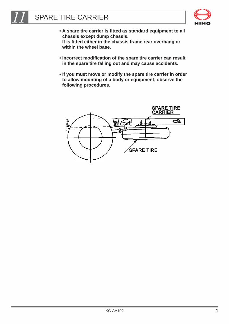
• A spare tire carrier is fitted as standard equipment to allchassis except dump chassis.It is fitted either in the chassis frame rear overhang orwithin the wheel base.
• Incorrect modification of the spare tire carrier can resultin the spare tire falling out and may cause accidents.
• If you must move or modify the spare tire carrier in order to allow mounting of a body or equipment, observe the following procedures.
SPARE TIRE CARRIER11
KC-AA102 1
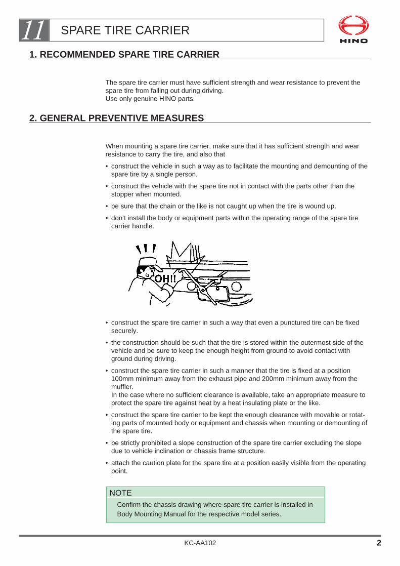
1. RECOMMENDED SPARE TIRE CARRIER
The spare tire carrier must have sufficient strength and wear resistance to prevent thespare tire from falling out during driving.Use only genuine HINO parts.
2. GENERAL PREVENTIVE MEASURES
When mounting a spare tire carrier, make sure that it has sufficient strength and wearresistance to carry the tire, and also that
• construct the vehicle in such a way as to facilitate the mounting and demounting of thespare tire by a single person.
• construct the vehicle with the spare tire not in contact with the parts other than thestopper when mounted.
• be sure that the chain or the like is not caught up when the tire is wound up.
• don’t install the body or equipment parts within the operating range of the spare tirecarrier handle.
• construct the spare tire carrier in such a way that even a punctured tire can be fixedsecurely.
• the construction should be such that the tire is stored within the outermost side of thevehicle and be sure to keep the enough height from ground to avoid contact withground during driving.
• construct the spare tire carrier in such a manner that the tire is fixed at a position100mm minimum away from the exhaust pipe and 200mm minimum away from themuffler.In the case where no sufficient clearance is available, take an appropriate measure toprotect the spare tire against heat by a heat insulating plate or the like.
• construct the spare tire carrier to be kept the enough clearance with movable or rotat-ing parts of mounted body or equipment and chassis when mounting or demounting ofthe spare tire.
• be strictly prohibited a slope construction of the spare tire carrier excluding the slopedue to vehicle inclination or chassis frame structure.
• attach the caution plate for the spare tire at a position easily visible from the operatingpoint.
NOTEConfirm the chassis drawing where spare tire carrier is installed inBody Mounting Manual for the respective model series.
SPARE TIRE CARRIER11
KC-AA102 2
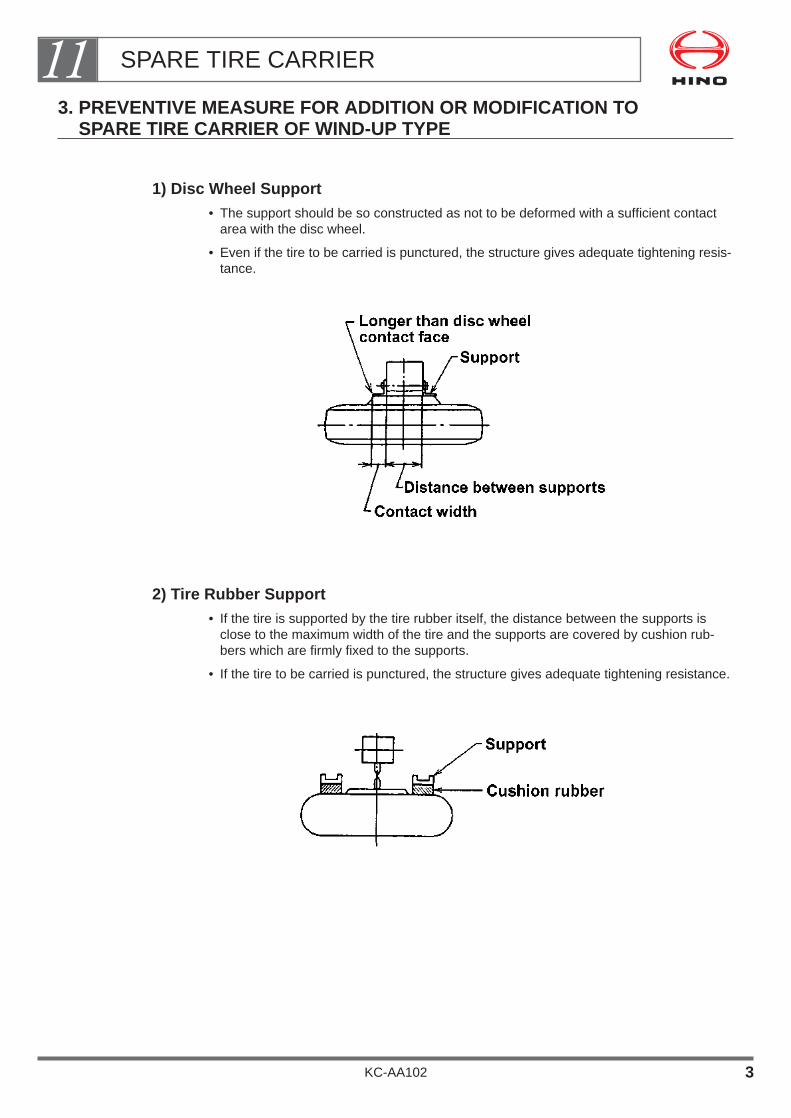
3. PREVENTIVE MEASURE FOR ADDITION OR MODIFICATION TOSPARE TIRE CARRIER OF WIND-UP TYPE
1) Disc Wheel Support• The support should be so constructed as not to be deformed with a sufficient contact
area with the disc wheel.
• Even if the tire to be carried is punctured, the structure gives adequate tightening resis-tance.
2) Tire Rubber Support• If the tire is supported by the tire rubber itself, the distance between the supports is
close to the maximum width of the tire and the supports are covered by cushion rub-bers which are firmly fixed to the supports.
• If the tire to be carried is punctured, the structure gives adequate tightening resistance.
SPARE TIRE CARRIER11
KC-AA102 3

It is therefore advised to install the disc stopper to the carrier itself or construct a suchthat tire disc is contacted with installation bracket as following figure.
4. SPARE TIRE CARRIER HANDLE
• The size of the arm of the crank handle (L) must be the length to be able to achieve thecarrier maker’s recommended tightening torque.
• The length of the arm, make sure that the operation of the crank handle is not obstruct-ed with other parts.
TIRE STOPPER DISC STOPPER
PUNCTURED TIRE DISC
The carrier must have a stopper that will give adequate tightening resistance even with a punctured tire.
NOTE• In the case of spare tire carrier with tire rubber support type, it is
difficult to get adequate tightening resistance when the tire to becarried is punctured.
SPARE TIRE CARRIER11
KC-AA102 4

5. SPARE TIRE CARRIER HANDLE GUIDE
Install the Handle Guide as Following Figure;
Details of Handle Guide Hole
6. CAUTION PLATE FOR CARRIER TIGHTENING TORQUE
• Fit a caution plate showing the proper tightening torque for the carrier in a visible loca-tion as close as possible to the carrier.
• The style of the caution plate should be similar to that of a genuine HINO caution plate.
SPARE TIRE CARRIER11
KC-AA102 5

BODY & EQUIPMENT MOUNTING
1. DESIGN OF BODY OR EQUIPMENT MOUNTING ・・・・ 2
2. SPACER・・・・・・・・・・・・・・・・・・・・・・・・・・・・・・・・・・・・・・・・・・10
3. MOUNTING METHOD OF BODY OR EQUIPMENT ・・・・11
4. INSPECTION LID・・・・・・・・・・・・・・・・・・・・・・・・・・・・・・・・・・17
5. REAR FENDER ・・・・・・・・・・・・・・・・・・・・・・・・・・・・・・・・・・18
6. CHASSIS FRAME ・・・・・・・・・・・・・・・・・・・・・・・・・・・・・・・・20
7. BODY OFFSET ・・・・・・・・・・・・・・・・・・・・・・・・・・・・・・・・・・21
8. DATUM HOLE ON REAR AXLE CENTER FOR BODY MOUNTING・・・・・・・・・・・・・・・・・・・・・・・・・・21
9. INSTALLATION OF UNDER RUN PROTECTION・・・・・・21
10. REAR BODY・・・・・・・・・・・・・・・・・・・・・・・・・・・・・・・・・・・・・・23
11. MOUNTING OF SPECIAL REAR BODY・・・・・・・・・・・・・・25
KC-AA102
Chapter 12
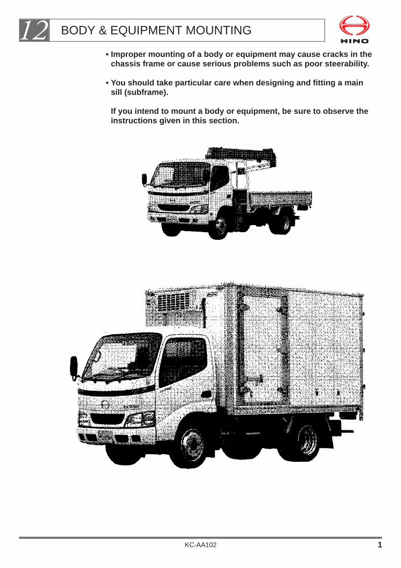
• Improper mounting of a body or equipment may cause cracks in thechassis frame or cause serious problems such as poor steerability.
• You should take particular care when designing and fitting a mainsill (subframe).
If you intend to mount a body or equipment, be sure to observe theinstructions given in this section.
BODY & EQUIPMENT MOUNTING12
KC-AA102 1

1. DESIGN OF BODY OR EQUIPMENT MOUNTING
1) Main Sill (Subframe)
When mounting the main sill on top of the side member, be sure that you position it so asto disperse the stress placed on the frame by loading.Also be sure to secure all mechanisms of the body equipment unit to the main sill, exceptfor the combination parts between the main sill and the chassis frame.
Fit a spacer between the main sill and the side member to lift the main sill off the rivetheads of the frame side member.
When mounting a body or equipment, always fit a main sill (subframe) on the top surface of the side member of thechassis frame.
BODY & EQUIPMENT MOUNTING12
KC-AA102 2

Relation of concentrated stress to forward end shape of main sill.
If the section modulus at the forward end of the main sill (subframe) changes suddenly,this will place concentrated stress on the chassis frame and may lead to cracks in theside members.
When mounting a body or equipment, make sure that the section modulus at the forwardend of the main sill (subframe) does not change suddenly.
Preventing concentrated stress around the forward end ofthe main sill (subframe).
BODY & EQUIPMENT MOUNTING12
KC-AA102 3

Forward End of Main Sill (Subframe)
The front end of the main sill, where it contacts the side member, must be shaped asshown in the drawings below.
BODY & EQUIPMENT MOUNTING12
KC-AA102 4
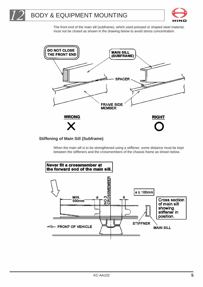
The front end of the main sill (subframe), which used pressed or shaped steel material,must not be closed as shown in the drawing below to avoid stress concentration.
Stiffening of Main Sill (Subframe)
When the main sill is to be strengthened using a stiffener, some distance must be keptbetween the stiffeners and the crossmembers of the chassis frame as shown below.
BODY & EQUIPMENT MOUNTING12
KC-AA102 5
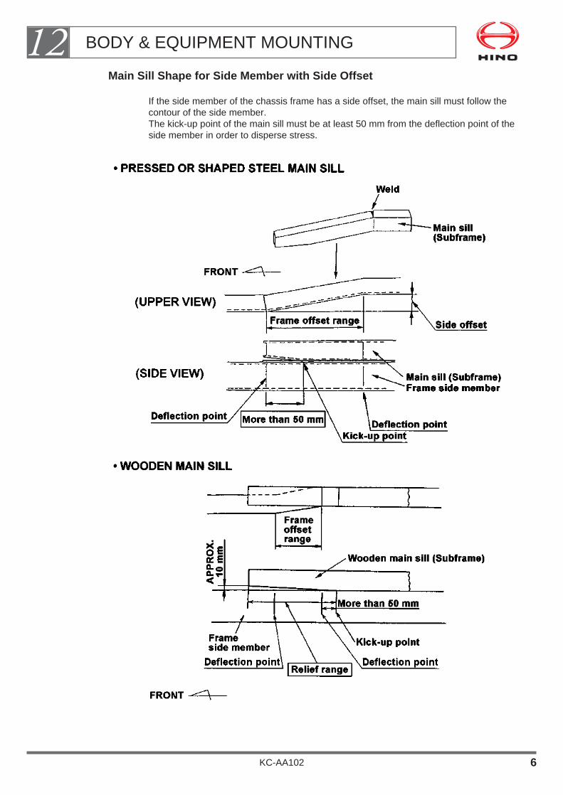
Main Sill Shape for Side Member with Side Offset
If the side member of the chassis frame has a side offset, the main sill must follow thecontour of the side member.The kick-up point of the main sill must be at least 50 mm from the deflection point of theside member in order to disperse stress.
BODY & EQUIPMENT MOUNTING12
KC-AA102 6

Extension of Main Sill (Subframe)
The main sill should extend as far as possible towards the back of the cab to minimizecar-shake (vibration) and prevent the creation of weak areas in the frame side member.
Positioning Forward End of Main Sill for Rigidity of Body or Equipment
For trucks with highly rigid bodies such as tank lorries, LPG lorries, and van body trucks(especially refrigerator trucks), etc., be sure to select the chassis model and design thebody so that the main sill extends as far as possible toward the back of the cab.
If for unavoidable reasons, such as axle mass distribution, you must leave a large gapbetween the body or equipment and the back of the cab, extend the main sill as far aspossible toward the back of the cab and secure it firmly to the chassis frame.
BODY & EQUIPMENT MOUNTING12
KC-AA102 7
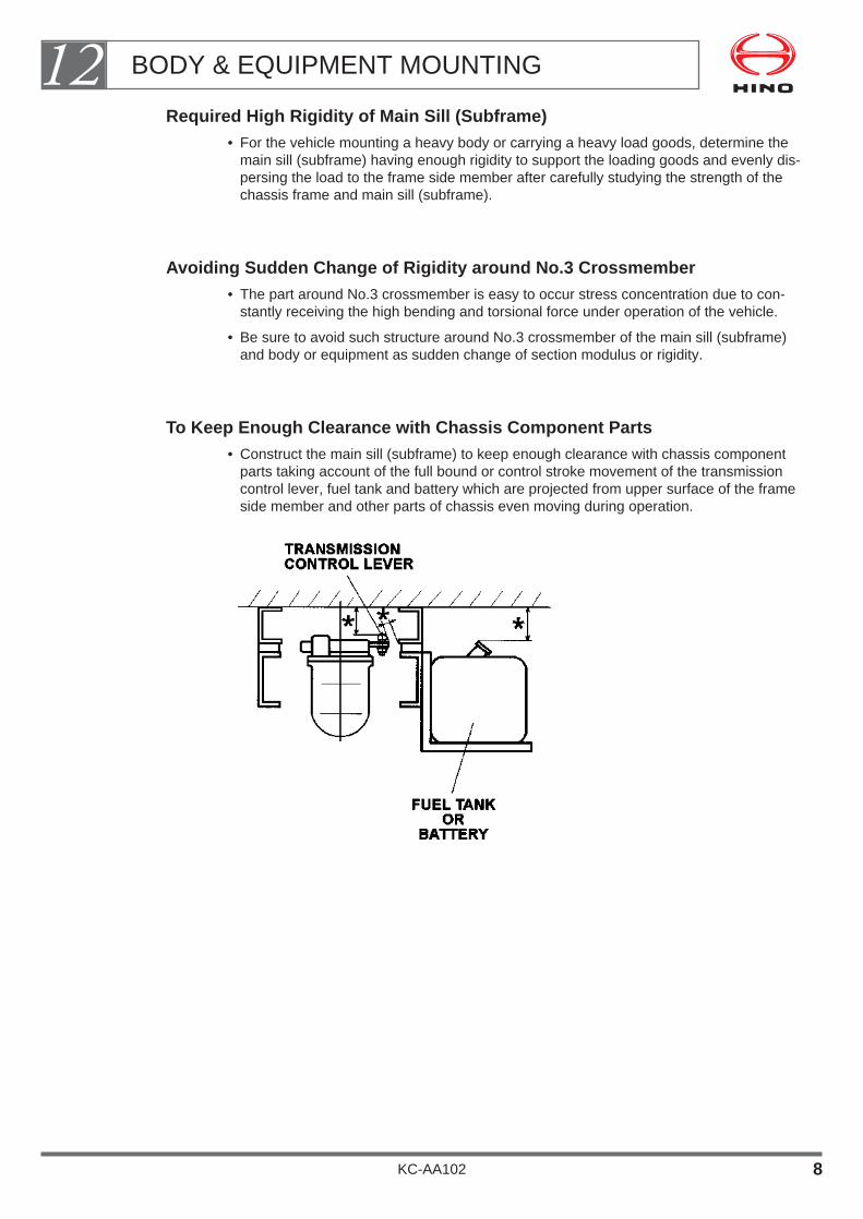
Required High Rigidity of Main Sill (Subframe)• For the vehicle mounting a heavy body or carrying a heavy load goods, determine the
main sill (subframe) having enough rigidity to support the loading goods and evenly dis-persing the load to the frame side member after carefully studying the strength of thechassis frame and main sill (subframe).
Avoiding Sudden Change of Rigidity around No.3 Crossmember• The part around No.3 crossmember is easy to occur stress concentration due to con-
stantly receiving the high bending and torsional force under operation of the vehicle.
• Be sure to avoid such structure around No.3 crossmember of the main sill (subframe)and body or equipment as sudden change of section modulus or rigidity.
To Keep Enough Clearance with Chassis Component Parts• Construct the main sill (subframe) to keep enough clearance with chassis component
parts taking account of the full bound or control stroke movement of the transmissioncontrol lever, fuel tank and battery which are projected from upper surface of the frameside member and other parts of chassis even moving during operation.
BODY & EQUIPMENT MOUNTING12
KC-AA102 8

Rear Body Length and Dimensions of Main Sill (Subframe)• For the vehicles having a long rear body, the sectional area of the main sill (subframe)
of the rear body should be set to a value greater than shown in the drawing.
Main Sill (Subframe) of Long Wheelbase Vehicles• A steel main sill (subframe) should be used for the long wheelbase vehicles.
• The use of a wooden or aluminum main sill (subframe) may bend the frame side mem-bers, often making the rear deck gate inoperable.
• With regard to vehicles with a concentrated load having a long wheelbase, use thestandard pressure-rolled structural steel material SS41 (Min. 120 mm high by 50 mmwide by 3.2 mm thick) or the like.
Provision Water Drain Hole of Main Sill(Subframe)• In the case of using a lip-formed steel ( channel-shaped) or closed section steel for
the main sill (subframe) and cross sill, water may deposit in the formed or closed steeloften causing rust.
• Be sure to provide a drain hole at a place where no strength problem is occurred.
BODY & EQUIPMENT MOUNTING12
KC-AA102 9

2. SPACER
When installing a main sill, insert a spacer between the side member of the chassisframe and the main sill to lift the main sill clear of the rivets in the upper surface of theframe.
If the body to be mounted will apply a concentrated load to the chassis frame as concretemixer body or like, the spacer should be made of a high strength material such as steelliner.
BODY & EQUIPMENT MOUNTING12
KC-AA102 10

3. MOUNTING METHOD OF BODY OR EQUIPMENT
How to Install the Main Sill (Subframe)
(1) Install the main sill (subframe) of the body or equipment on the chassis using U-bolts or brackets.
The details of mounting methods are shown in the drawings below.
If the main sill (subframe) even if made of steel to be secured to the chassis, should notbe fixed on the frame by welding or bolting on the frame upper flange.
BODY & EQUIPMENT MOUNTING12
KC-AA102 11
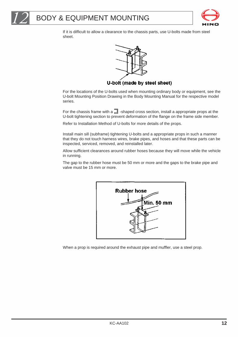
If it is difficult to allow a clearance to the chassis parts, use U-bolts made from steelsheet.
For the locations of the U-bolts used when mounting ordinary body or equipment, see theU-bolt Mounting Position Drawing in the Body Mounting Manual for the respective modelseries.
For the chassis frame with a -shaped cross section, install a appropriate props at theU-bolt tightening section to prevent deformation of the flange on the frame side member.
Refer to Installation Method of U-bolts for more details of the props.
Install main sill (subframe) tightening U-bolts and a appropriate props in such a mannerthat they do not touch harness wires, brake pipes, and hoses and that these parts can beinspected, serviced, removed, and reinstalled later.
Allow sufficient clearances around rubber hoses because they will move while the vehiclein running.
The gap to the rubber hose must be 50 mm or more and the gaps to the brake pipe andvalve must be 15 mm or more.
When a prop is required around the exhaust pipe and muffler, use a steel prop.
BODY & EQUIPMENT MOUNTING12
KC-AA102 12

It is desirable to install the U-bolts at the U-bolt mounting positions (standard positions)shown on the below. Installing U-bolts at other positions will impair the frame strength. Asa rule, do not install U-bolts at the positions listed below. If it is unavoidable to install U-bolts at prohibited positions, carefully verify the frame strength.
Point where there is a difference in level on the chassis frame (frame kick point) and theside offset point (side kick point)
The U-bolt mounting position must be 50 mm or more away from the frame kick point.
Existing hole in the flange of the frame side railThe U-bolt mounting position must be 40 mm or more away from the existing hole.
Break point of the frame's inner or outer reinforcement (the section modulus changegreatly)
The U-bolt mounting position must be 100 mm or more away from the break point ofthe inner or outer reinforcement.
Near the crossmemberAs a rule, the U-bolt mounting position must be 200 mm or more away from the
crossmember. If impossible, the U-bolt must be at least 100 mm away from the cross-member.
Stress release point at front end of man sill (subframe).
The details where U-bolt should be installed, see the Body Mounting Manual for therespective model series.
[PROHIBITED RANGE WHERE U-BOLT SHOULD NOT BE INSTALLED]
BODY & EQUIPMENT MOUNTING12
KC-AA102 13

Installation Method of U-bolts
For the frame side member which is fastened with a U-bolt, use appropriate props to sup-port the frame side member so that the lower flange may not be deformed.
Sufficient clearance should be allowed to prevent the props from contacting brake pipes,hoses, cables, harness wires etc.
In an area close to the muffler, use a steel prop to prevent burning.
BODY & EQUIPMENT MOUNTING12
KC-AA102 14
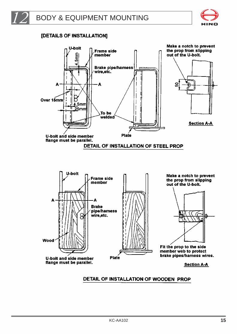
BODY & EQUIPMENT MOUNTING12
KC-AA102 15

Use of Mounting Brackets
Follow the cautions below in the case where it is unavoidable to use mounting bracketsbecause of the inability of installing a U-bolt due to the mounted body or equipment struc-ture.
Installing mounting brackets near crossmembers may place high stress on the side mem-ber.Mounting brackets must therefore be positioned at least 200 mm away from the anycrossmembers.
If the mounting brackets must be mounted within 200 mm of the end of crossmember,they should be positioned at the center of crossmember.
Secure mounting brackets to the chassis frame side member with bolts.Be sure not to damage brake pipes or harness wires when drilling holes in the chassisframe.
For a general description of how to drill holes in the chassis frame, see clause "2. CHAS-SIS FRAME".
BODY & EQUIPMENT MOUNTING12
KC-AA102 16
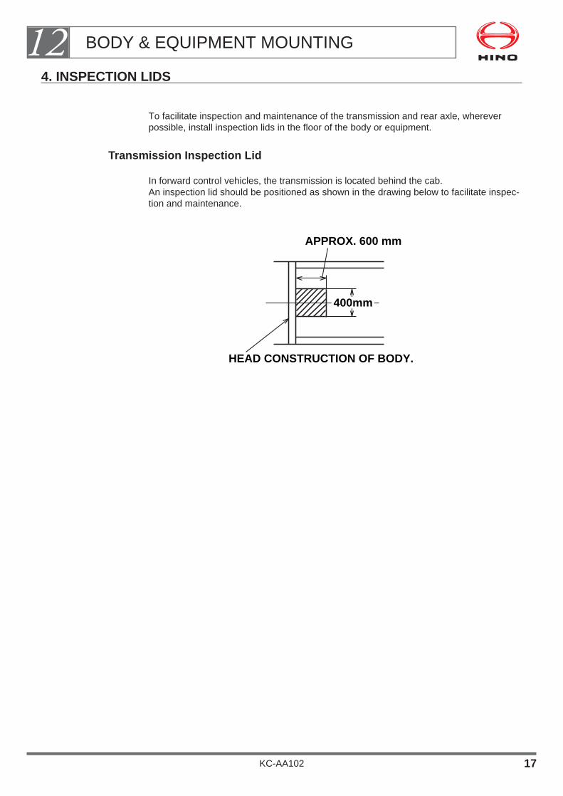
4. INSPECTION LIDS
To facilitate inspection and maintenance of the transmission and rear axle, whereverpossible, install inspection lids in the floor of the body or equipment.
Transmission Inspection Lid
In forward control vehicles, the transmission is located behind the cab.An inspection lid should be positioned as shown in the drawing below to facilitate inspec-tion and maintenance.
APPROX. 600 mm
HEAD CONSTRUCTION OF BODY.
400mm
BODY & EQUIPMENT MOUNTING12
KC-AA102 17

5. REAR FENDER
Precautions for Installing Rear Fenders
Install the rear fenders conforming to vehicle safety regulations, and allow sufficientclearance between the tires and the floor of the body or equipment so that the tires donot contact the fenders.
For details of clearances, see Maximum Vertical Deflection of Rear Wheels in the BodyMounting Manual for the respective model series.If there is a possibility that tire chains may have to be fitted, you should allow an extraclearance of 50 mm.
For safety and extra rigidity, the outer edge of the rear fender should turn inward asshown in the drawing below.The inside edge should also be turned inward of rigidity.
The outer edge of the fender should project at least 10 mm beyond the side of the tireand provided the overall width of the fender does not exceed overall width of the vehicle.
BODY & EQUIPMENT MOUNTING12
KC-AA102 18
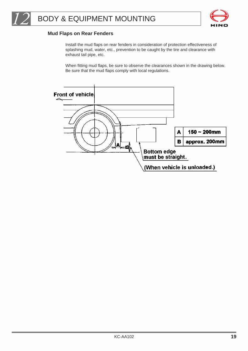
Mud Flaps on Rear Fenders
Install the mud flaps on rear fenders in consideration of protection effectiveness ofsplashing mud, water, etc., prevention to be caught by the tire and clearance withexhaust tail pipe, etc.
When fitting mud flaps, be sure to observe the clearances shown in the drawing below.Be sure that the mud flaps comply with local regulations.
BODY & EQUIPMENT MOUNTING12
KC-AA102 19

6. CHASSIS FRAME
Rivet Dimensions
The drawing below shows the dimensions of the rivets used in the chassis frame.
When mounting a main sill (subframe) you will need to allow holes to accommodate therivet heads either in the main sill itself or in a spacer.
Tolerances of Chassis Frame Assembly Width and Height
BODY & EQUIPMENT MOUNTING12
KC-AA102 20

7. BODY OFFSET
For mounting the dump or concrete mixer body, determine the body offset as small aspossible in order to get enough load on the rear tires getting good driving ability onunpaved road.
8. DATUM HOLE ON REAR AXLE CENTER FOR BODY MOUNTING
When body offset position on the chassis frame is to be determined, make use of rearaxle datum line holes (ø9) on the frame side member.
9. INSTALLATION OF UNDER RUN PROTECTION
In the case of installing the under run protection parts as side guard and rear bumper,etc. to comply with local vehicle regulation, install it after carefully studying the followingpoints;
Dimensions and shape must be complied with regulation.(ground height, size and shape of parts)
Strength of installation and parts it's self must also be complied with regulation.
Installation must be by bolts to the cross sill or main sill (subframe) of body and shouldbe detachable construction.
Be sure not to install it to the chassis frame side member, fuel tank or battery support.
Be sure not to obstruct the service and maintenance ability for chassis component parts.
• Easy inspection of electrolyte level and easy removal of the battery.
• Easy filling and easy removal and replacement of filler cap of the fuel tank.
• Easy removal and easy installation of the spare tire.
• Opening and closing of the tool box cover.
BODY & EQUIPMENT MOUNTING12
KC-AA102 21
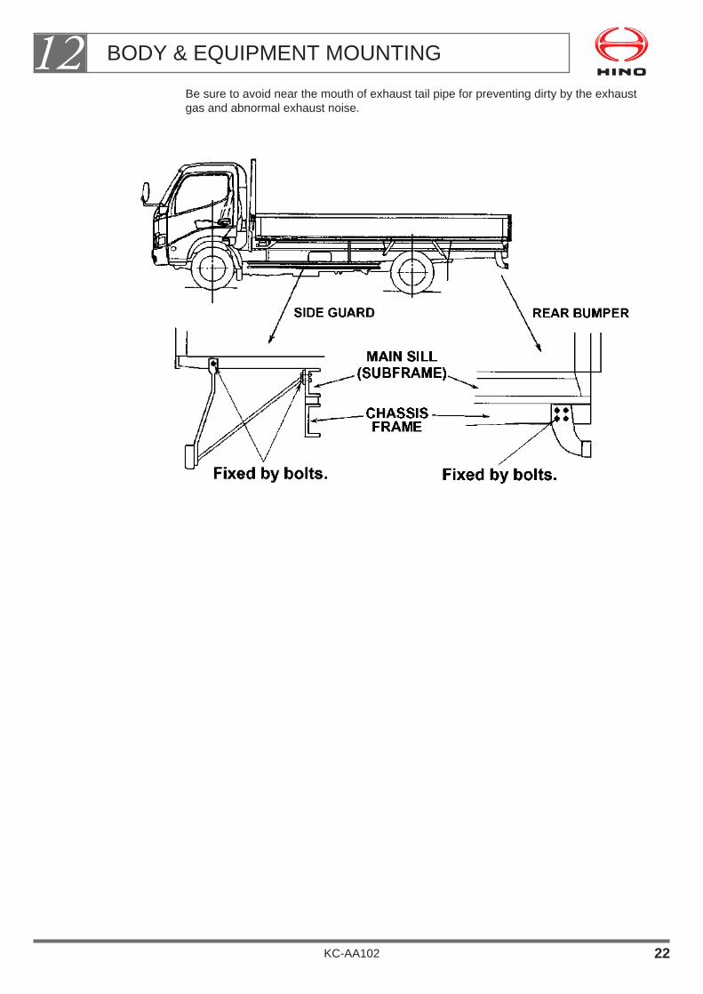
Be sure to avoid near the mouth of exhaust tail pipe for preventing dirty by the exhaustgas and abnormal exhaust noise.
BODY & EQUIPMENT MOUNTING12
KC-AA102 22

10. REAR BODY
• In order to prevent intrusion of dust and exhaust gas into the rear body, securely sealall the holes and apertures in the body floor (deck) except water drain hole as dumpbody.
• Don't remove the insulator from base vehicle.
• When mounting a rear body, must be taken the following precautions;
Prevention of Cargo Drop
Each customer (driver) is responsible for preventing his/her cargo from falling.The body-builder therefore is required to take a measure for cargo-fall prevention mostsuitable for the normal cargo of the particular customer.
Since the general cargo can be bound only laterally, the front portion of the deck is effec-tively covered with a wire mesh or iron sheets.
In the case of dump body, a rear view window on the front wall of the vessel is effectivelycovered with a wire mesh and a protector (steel cover) must be also installed on frontportion on the subframe.
.
BODY & EQUIPMENT MOUNTING12
KC-AA102 23
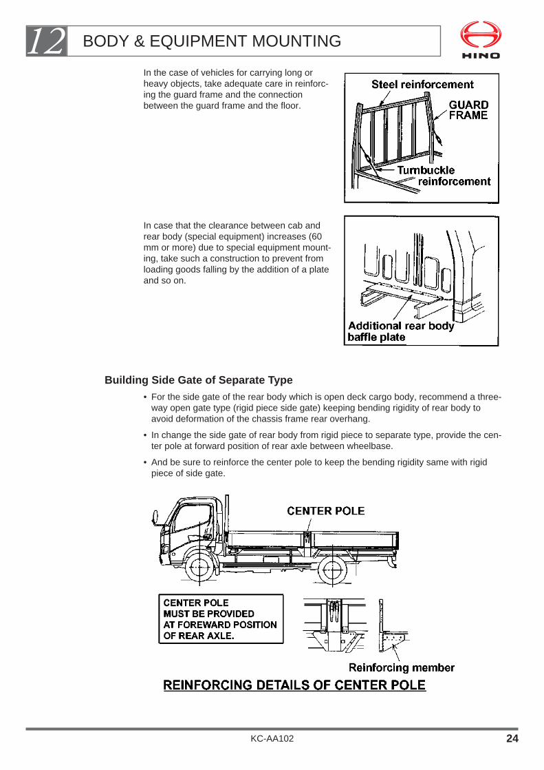
In the case of vehicles for carrying long orheavy objects, take adequate care in reinforc-ing the guard frame and the connectionbetween the guard frame and the floor.
In case that the clearance between cab andrear body (special equipment) increases (60mm or more) due to special equipment mount-ing, take such a construction to prevent fromloading goods falling by the addition of a plateand so on.
Building Side Gate of Separate Type• For the side gate of the rear body which is open deck cargo body, recommend a three-
way open gate type (rigid piece side gate) keeping bending rigidity of rear body toavoid deformation of the chassis frame rear overhang.
• In change the side gate of rear body from rigid piece to separate type, provide the cen-ter pole at forward position of rear axle between wheelbase.
• And be sure to reinforce the center pole to keep the bending rigidity same with rigidpiece of side gate.
BODY & EQUIPMENT MOUNTING12
KC-AA102 24
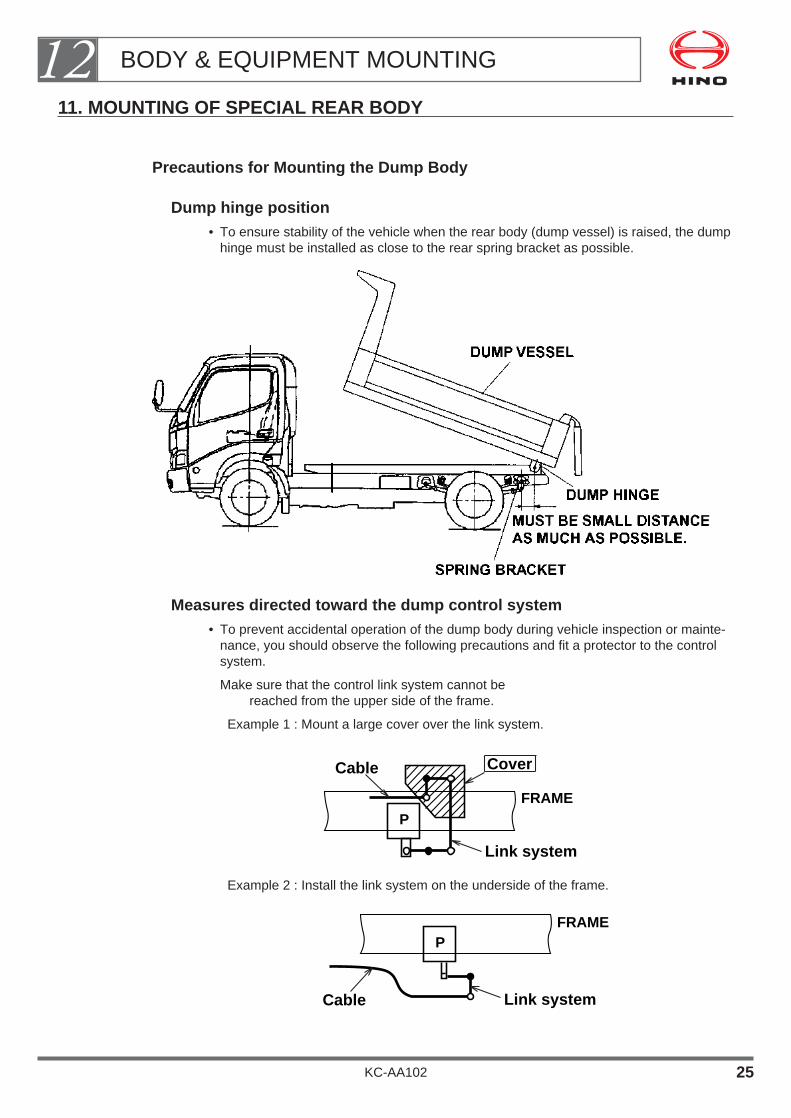
11. MOUNTING OF SPECIAL REAR BODY
Precautions for Mounting the Dump Body
Dump hinge position• To ensure stability of the vehicle when the rear body (dump vessel) is raised, the dump
hinge must be installed as close to the rear spring bracket as possible.
Measures directed toward the dump control system• To prevent accidental operation of the dump body during vehicle inspection or mainte-
nance, you should observe the following precautions and fit a protector to the controlsystem.
Make sure that the control link system cannot be reached from the upper side of the frame.
Example 1 : Mount a large cover over the link system.
Example 2 : Install the link system on the underside of the frame.
Cable
P
Link system
FRAME
Cable
P
Cover
Link system
FRAME
BODY & EQUIPMENT MOUNTING12
KC-AA102 25

Example 3:
Connect the control cable directly to the hydraulic pump to eliminate theneed for intermediate link levers, etc.
Make sure that the link levers are easily accessible for lubrication or if possible use oil-less link levers.
Examples :
• Fit the lubrication port on the side of the frame
• Mount the link levers so that they can be lubricated from the underside of the chassisframe, without raising the load platform.
• Use an oilless link system.
Make sure that any operating levers inside the cab lock automatically in both ON andOFF positions.
Precaution for routing the dump control cable
The dump control lever was installed as optional equipment
when the chassis was assembled.
Design and install the control cable while mounting the rear body.
Route the cable in such a manner that it does not touch the edges of the frame andbrackets and the movable portions such as various control links and engine.
After routing the dump control cable, check that it does not touch the above edges andmovable portions. Do not forget to check that the dump control lever does not touch theshift lever by operating the shift lever.
Cable
PFRAME
BODY & EQUIPMENT MOUNTING12
KC-AA102 26

About the safety block
The structure of the safety block (or safety rod) must be designed so that it can be lockedand released easily.
Example of structure:
The safety block (or safety rod) is installed on the subframe and it isturned up or down (manually).
Inside the cab and also the both sides of the subframe, affix a CAUTION plate explainingthe cautions about the handling of the safety block, near the safety block (or safety rod).
Inside the cab and also the both sides of the subframe, affix the CAUTION plate explain-ing the precautions to be followed when the rear body is raised.
About the instruction manual
In the Instruction Manual, explain the following topics in an easy style:
• How to operate the dump system
• How to operate the safety block and dump lever lock
BODY & EQUIPMENT MOUNTING12
KC-AA102 27

BODY & EQUIPMENT CONTROLS
1. POWER TAKE OFF (P.T.O.) ・・・・・・・・・・・・・・・・・・・・・・・・ 2
2. P.T.O. (POWER TAKE OFF) DRIVE SHAFT ・・・・・・・・・・ 4
3. ENGINE CONTROLS FOR BODY OR EQUIPMENT ・・・・・・・・・・・・・・・・・・・・・・・・・・・・・・・・・・・・ 6
4. ENGINE CONTROLS FOR MECHANICAL GOVERNOR ・・・・・・・・・・・・・・・・・・・・・・10
5. P.T.O. CONTROL (TRANSMISSION SIDE P.T.O.)・・・・・・11
KC-AA102
Chapter 13

• After mounting a body or equipment, you may need to take a power supply fromthe chassis and fit controls for the body or equipment.
• When making these modifications, be sure to observe the following precautions.
BODY & EQUIPMENT CONTROLS13
KC-AA102 1

1. POWER TAKE OFF (P.T.O.)
• Hino truck series may be provided the Power Take Off (P.T.O.) in described followingfigure as an option equipment.
General Precautions of P.T.O.
For the P.T.O. fixed to transmission or engine, never permit the unit to exceed the torqueand r.p.m. recommended by Hino.
[EXAMPLE FOR TRANSMISSION SIDE P.T.O.]
• For details of permissible torque and recommended r.p.m., see the Body MountingManual for the respective model series.
When the P.T.O. is operated for a long time in the ordinary condition, a heat protectionfixture such as a heat insulator should be provided in order to prevent fuel vaporization and protect cables, hoses, tubesand wirings from high heat emitted from exhaust manifolds and exhaust pipes.
BODY & EQUIPMENT CONTROLS13
KC-AA102 2

The devices of the body or equipment (e.g.an oil pump) which will be intended to drive byP.T.O., must be securely fixed at same installation angle of engine to the body or equip-ment side via bracket, etc.
THE DIRECT FIXING THE DEVICES TO THE P.T.O. OUTPUTFLANGE IS STRICTLY PROHIBITED.
BODY & EQUIPMENT CONTROLS13
KC-AA102 3

2. P.T.O. (POWER TAKE OFF) DRIVE SHAFT
You may decide to fit a drive shaft to the engine rear P.T.O. or the transmission sideP.T.O.
If the installing angle of this drive shaft is too large, it will cause noise and vibration, andmay cause damage.
When fitting the drive shaft be sure to observe the following precautions.
Mounting Angles for Devices of Body and Equipment
The devices on the body or equipment side (e.g. oil pump) must be installed at the sameangle as the engine ( ), and the angles of the universal joint of the drive shaft (D1 andD2) must be the same.
Drive Shaft Angle
As a rule, the three-dimensional angle of the universal joint of the drive shaft (D1,D2 andD3) should be a MIN.1° to MAX. 6°.
BODY & EQUIPMENT CONTROLS13
KC-AA102 4

Length of Drive Shaft
To keep vibration during driving to a minimum, HINO recommend that the drive shaftshould be no longer than the values shown in the table below.
If you must make the shaft longer than the values shown in the table, fit a central bearingto avoid excessive vibration.
BODY & EQUIPMENT CONTROLS13
KC-AA102 5
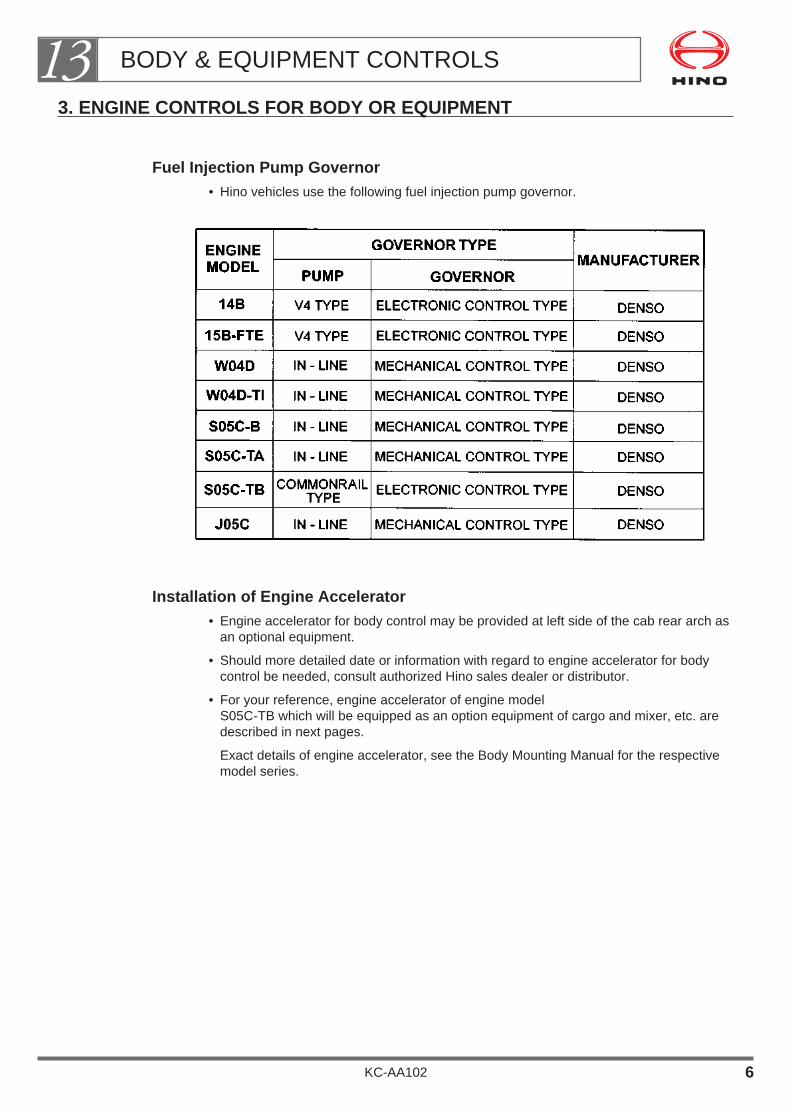
3. ENGINE CONTROLS FOR BODY OR EQUIPMENT
Fuel Injection Pump Governor• Hino vehicles use the following fuel injection pump governor.
Installation of Engine Accelerator• Engine accelerator for body control may be provided at left side of the cab rear arch as
an optional equipment.
• Should more detailed date or information with regard to engine accelerator for bodycontrol be needed, consult authorized Hino sales dealer or distributor.
• For your reference, engine accelerator of engine model S05C-TB which will be equipped as an option equipment of cargo and mixer, etc. aredescribed in next pages.
Exact details of engine accelerator, see the Body Mounting Manual for the respectivemodel series.
BODY & EQUIPMENT CONTROLS13
KC-AA102 6

EXAMPLE
[ENGINE ACCELERATOR FOR ELECTRONIC GOVERNOR]
• Engine Model : S05C-TB• Cab Type : Wide• Application of Body : General cargo UNIT : mm
BODY & EQUIPMENT CONTROLS13
KC-AA102 7

EXAMPLE
[HOW TO INSTALL ENGINE ACCELERATOR FOR BODY OR EQUIPMENT](ELECTRONIC GOVERNOR ONLY)
Be sure to provide the body controller with the full speed stopper for controlling the strokeof the sensor.
In that case, adjust the body side stroke stopper in such a way that the body side stoppercomes in contact earlier than the sensor side stopper.
The standard for adjustment is 1 mm clearance between the sensor side lever and stop-per under the condition that the body side lever touches the stopper. (See the followingillustration.)
• Be sure to set the sensor lever that sensor lever should be contacted with idling stop-per by adjusting body control lever while body or equipment do not operate (while vehi-cle is driving).
• The clearance indicated for the stroke stopper of accelerator stopper is just for refer-ence.
If the sensor side stopper comes into contact earlier, a forcible stress will be imposedon the sensor shaft and it may result in the damage of the part in cause.
Moreover, if sensor lever do not came into contact with idling stopper, may result in abad condition of the engine while vehicle to be driving.
BODY & EQUIPMENT CONTROLS13
KC-AA102 8
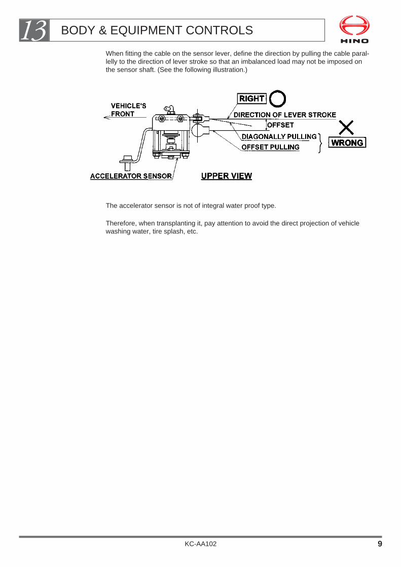
When fitting the cable on the sensor lever, define the direction by pulling the cable paral-lelly to the direction of lever stroke so that an imbalanced load may not be imposed onthe sensor shaft. (See the following illustration.)
The accelerator sensor is not of integral water proof type.
Therefore, when transplanting it, pay attention to avoid the direct projection of vehiclewashing water, tire splash, etc.
BODY & EQUIPMENT CONTROLS13
KC-AA102 9

4. ENGINE CONTROLS FOR MECHANICAL GOVERNOR(WITHOUT OPTIONAL ENGINE ACCELERATOR)
Engine Control for Body
If you intend to fit a device to control engine revolutions when working with a body orequipment, make sure that the device is able to absorb the relative movement betweenthe engine and the chassis (installing of control lever for body or equipment, etc.).
If the mechanism cannot absorb the relative motion, the control lever of the injectionpump may be moved by the normal vibration of the engine (displacement) and abnormalvibrations may arise while operating a body or equipment.
Relative movement of engine and chassis absorbed.
Relative movement of engine and chassis not absorbed.
BODY & EQUIPMENT CONTROLS13
KC-AA102 10
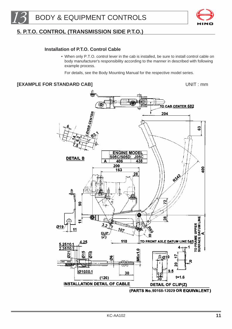
5. P.T.O. CONTROL (TRANSMISSION SIDE P.T.O.)
Installation of P.T.O. Control Cable• When only P.T.O. control lever in the cab is installed, be sure to install control cable on
body manufacturer's responsibility according to the manner in described with followingexample process.
For details, see the Body Mounting Manual for the respective model series.
[EXAMPLE FOR STANDARD CAB] UNIT : mm
BODY & EQUIPMENT CONTROLS13
KC-AA102 11

RECOMMENDED INSTALLATION LAYOUT OF P.T.O. CONTROL CABLE
[EXAMPLE FOR STANDARD CAB] UNIT : mm
• Details of each model, see the Body Mounting Manual for the respective model series.
BODY & EQUIPMENT CONTROLS13
KC-AA102 12
PAINTING
1. TOP COAT PAINTING・・・・・・・・・・・・・・・・・・・・・・・・・・・・・・ 1
2. PRECAUTION OF TOP COAT PAINTING FOR CAB ・・・・・・・・・・・・・・・・・・・・・・・・・・・・・・・・・・・・・・・・・・ 2
3. HANDLING OF LAMINATED WINDSHIELD ・・・・・・・・・・ 4
4. HOW TO REMOVE THE RADIATOR GRILLE ・・・・・・・・ 5
5. THE KIND AND THE ATTACHING POSITION OF MARK AND ORNAMENT ・・・・・・・・・・・・・・・・・・・・ 6
6. PRECAUTIONS FOR FITTING AND STORING THE CAUTION PLATE ・・・・・・・・・・・・・・・・・・・・・・・・・・ 9
KC-AA102
Chapter 14

1. TOP COAT PAINTING
Take a care to the following points, when required to repaint it by acustomer.
Sanding
When repainting, perform to sand the original coat carefully not to be left any part no-sanded, in order to improve the adhesion of top coat paint. And, never remove offsealant, adhesive agent at connecting parts of the metal sheet.
[Sanding surface]
How to Choose Top Coat Paint
When painting on the metal parts
Hino recommends urethane-type, natural air drying paint to be used, which have superiorcharacteristics as in painting finish quality, color fade-out, comparing with lacquer-typepaint. The top coat should be at least 30 thick.
When painting on the resin parts
• Hino recommends paint for the resin parts to be used, which is best matched to thecharacteristics of the resin parts (step rubber, front-grill, front garnish, etc.) and also,can prevent to lowering the shock resistant force at low temperature.
• Then, Avoid to paint backside of the resin parts as its shock resistant force lowers fur-ther down with the both side to be painted, of the resin parts.
• Cab step, made of polypropylene material, can not be painted.
PAINTING14
KC-AA102 1
2. PRECAUTION OF TOP COAT PAINTING FOR CAB
Cautions for Cab Painting
When painting the cab, take a caution to the following points, other thanabove.
The place and parts to be omitted from painting for cab and mounting body as well asadhesion of all kinds of oil:
• Various kinds of the ornaments, marks.
• Various kinds of caution plates, labels.
• Relating equipments and parts to the brake as well as a brake hose.
• Various types of rubber hoses.
• Electrical wiring, connectors, electrical lamps, electrical switch, relating equipments andparts.
• Back-up buzzer, noise emitting hole of electric horn.
• Rubber and plastic parts of cab, engine, chassis suspension and steering system.
• Rubber hose for cab-tilt, piston rod of the cylinder for cab-tilt. (The vehicle with ahydraulic cab-tilt, driven by an electrical motor)
• Batteries
• Wiper blade, washer nozzle.
• Installing surface of disc to the disc wheel. (Including the hub to be contacted and con-tacting surface of drum, disc wheel as well as contacting surface of hub nuts.)Then, when stained paint to the inner part of the cab, cleaning it with a neutral deter-gent, do not use gasoline or thinner.
Caution when Drying• When you use forced drying, a temperature on the surface of any parts to be painted
must be 80°C as an upper limit.
Removing off any plastic parts, rubber parts from the vehicle, paint them when you usea forced drying at over 80°C. (Refer to the figure as shown below.)
Take care to those as plastic parts like fender, air cleaner, etc. are much used.
• When a vehicle with air-conditioning whose all piping and hosing are heated at abnor-mal temperature(more than 100°C), a pressure safety valve may function and come out refrigerant gas.
• When removing off a air-cleaner assy, seal completely the inlet port side of engine toprevent any penetration of dirt, paint or etc.
Also, install hoses securely and clamp them firmly when mounting them.
• Remove off the parts shown below when painting at over 80°C.
PAINTING14
KC-AA102 2
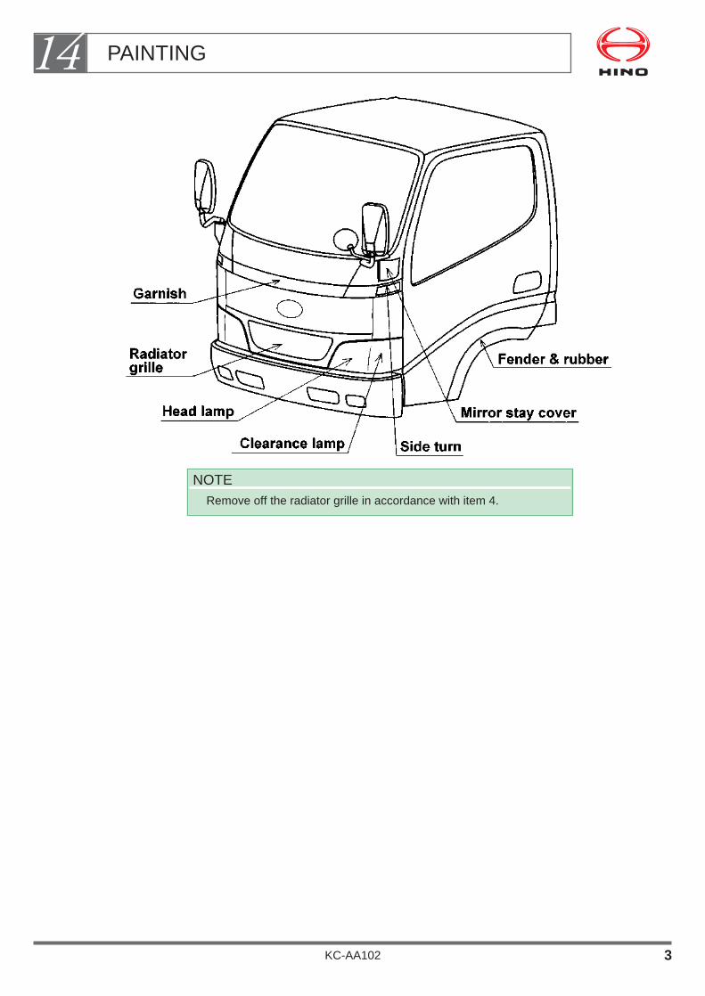
NOTERemove off the radiator grille in accordance with item 4.
PAINTING14
KC-AA102 3
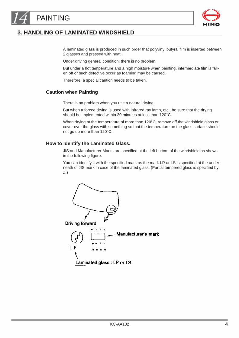
3. HANDLING OF LAMINATED WINDSHIELD
A laminated glass is produced in such order that polyvinyl butyral film is inserted between2 glasses and pressed with heat.
Under driving general condition, there is no problem.
But under a hot temperature and a high moisture when painting, intermediate film is fall-en off or such defective occur as foaming may be caused.
Therefore, a special caution needs to be taken.
Caution when Painting
There is no problem when you use a natural drying.
But when a forced drying is used with infrared ray lamp, etc., be sure that the dryingshould be implemented within 30 minutes at less than 120°C.
When drying at the temperature of more than 120°C, remove off the windshield glass orcover over the glass with something so that the temperature on the glass surface shouldnot go up more than 120°C.
How to Identify the Laminated Glass.JIS and Manufacturer Marks are specified at the left bottom of the windshield as shownin the following figure.
You can identify it with the specified mark as the mark LP or LS is specified at the under-neath of JIS mark in case of the laminated glass. (Partial tempered glass is specified byZ.)
PAINTING14
KC-AA102 4

4. HOW TO REMOVE THE RADIATOR GRILLE
How to Remove Off the Radiator Grille• Loosen the tapping screw, in the central part.
• Inserting your fingers into the clips underneath to pull them toward you, remove theclips.
• Remove the clips in the same manner at the side.
Remove the clips from right side of the vehicle (left side when viewed in front of thevehicle).
How to Install the Radiator Grille• Install the clips on the radiator grille.
• Install the radiator grille on the cab body by matching the clips holes and pushing it inthe order from the bottom to the upper side.
• Install the tapping screw at the central part.
Caution• After confirming that there are no damages at nail part, etc.,
of the clips, install them.
NOTEDetails of the how to remove the radiator grille, see the BodyMounting Manual for the respective model series.
PAINTING14
KC-AA102 5

5. THE KIND AND THE ATTACHING POSITION OF MARK AND ORNAMENT
The kind and the position to be attached of marks and ornaments on the cab as well asthe chassis are specified in the chart below.
Implement masking them completely when repainting the cab or the body.
When the marks and the ornaments to be attached on cab are packed separately andshipped out together with the vehicle, or when attaching them after complete painting,attach them at the specified places in accordance with the attaching position chart andthe attaching procedure.
NOTE• Parts numbers are changeable always. Accordingly, for confirmation,
get in contact with nearest Hino sales dealer or distributor when youplace an order for necessary parts.
• Detail of marks, see the Body Mounting Manual for the respectivemodel series.
PAINTING14
KC-AA102 6

Attaching Place and Procedure for Each Mark and Ornament
Refer to the detailed figure of the attaching position for 1 to 5 of the attachments on thecab.
(REAR VIEW OF VEHICLE)
(SIDE VIEW OF CAB)(FRONT VIEW OF CAB)
PAINTING14
KC-AA102 7

Attachment of Each Mark and Ornament
The detail of attaching position
(CAB SIDE VIEW)
(CAB FRONT VIEW)
PAINTING14
KC-AA102 8

6. PRECAUTIONS FOR FITTING AND STORING THE CAUTION PLATE
How to Stick It
Stick the caution plate to a dry place which is free from dust and dirt after the paint hascompletely dried up.
Clean your hand and don't use cotton work gloves, etc..
Completely remove water, oil, dust, etc. from the surface to stick (surface of cab) withethyl alcohol if they are found remaining there.
When the temperature is less than 10°C, warm up the surface to stick as well as the cau-tion plate with warm wind of more than 20°C before sticking the caution plate.
After sticking the caution plate, press it with a roller, etc., with a force of approximately 49N/cm2 {5 kgf/cm2 }.
Remove liner paper (backing paper) just before using it.
When air remains inside, make a tiny hole with a needle or a cutter knife and press it outwith your fingers from the bubble area.
How to Store It
When storing the caution plate, select a dry place with an ambient temperature (of 20 to25°C) and without dust, dirt and stain.
Also, store the caution plate at a flat place such as a shelf, etc., and do not place any-thing on it.
Other Precautions for the Caution Plate
As the caution plate is made from vinyl chloride, it is thin, soft and easily extendible.
Therefore, take utmost care for handling it.
When removing the caution plate, etc., be careful not to damage the painted surface witha sharp knife, etc.
On the other hand, removal of the caution plate can be done more easily by pulling thecaution plate in perpendicular direction to the sticking surface while heating it with a hairdryer.
Do not throw the caution plates away but keep them together to compare with new cau-tion plates and to prevent mixing up with the new ones.
PAINTING14
KC-AA102 9