Series G Moulded Case Circuit Breakers • Up to 690 Vacnanotechnologiess.com/images/eaton/sge/01_...
46
Series G Moulded Case Circuit Breakers Product Guide – Second Edition • Up to 690 Vac • 18kA to 100kA I cu • 16-2500 Amperes • IEC 60947-2 Safety, Reliability and Performance verified with the KEMA KEUR mark
Transcript of Series G Moulded Case Circuit Breakers • Up to 690 Vacnanotechnologiess.com/images/eaton/sge/01_...
Series G
Moulded Case Circuit Breakers
Product Guide – Second Edition
© 2004 Eaton Electric LimitedAll rights reserved
Printed in UKForm No PG0120002UJanuary 2005
Eaton Electric LimitedReddings Lane
Birmingham B11 3EZ
United Kingdom
Customer Support Centre
Tel: +44 (0)8700 545 333
Fax: +44 (0)8700 540 333
email: [email protected]
Eaton Electric NV
PO Box 23
7550 AA Hengelo
The Netherlands
Customer Support Centre
Tel: +31 (0)74 246 7066
Fax: +31 (0)74 246 7070
email: [email protected]
Eaton’s Electrical business is a global leader in electrical control, powerdistribution, and industrial automation products and services. Throughadvanced product development, world-class manufacturing methods, and global engineering services and support, Eaton’s Electrical businessprovides customer-driven solutions under brand names such as Cutler-Hammer®, Durant®, Heinemann®, Holec® and MEM®, whichglobally serve the changing needs of the industrial, utility, lightcommercial, residential, and OEM markets. For more information, visitwww.EatonElectrical.com.
Eaton Corporation is a diversified industrial manufacturer with 2003 salesof $8.1 billion. Eaton is a global leader in fluid power systems andservices for industrial, mobile and aircraft equipment; electrical systemsand components for power quality, distribution and control; automotiveengine air management systems and powertrain controls for fueleconomy; and intelligent drivetrain systems for fuel economy and safetyin trucks. Eaton has 54,000 employees and sells products to customers inmore than 100 countries. For more information, visit www.eaton.com.
• Up to 690 Vac
• 18kA to 100kA Icu• 16-2500 Amperes
• IEC 60947-2
Safety, Reliability
and Performance
verified with the
KEMA KEUR mark
EE MCCB Series G PG Cov reprint 20/1/05 4:20 pm Page 1

EE MCCB Series G PG Cov reprint 20/1/05 4:20 pm Page 3

January 2005
1Moulded Case Circuit Breakers16 – 2500 Amperes for IEC Applications
Series G Frame Sizes GE through GR (16 – 2500 Amperes)
Description Page
Standards . . . . . . . . . . . . . . . . 1General Information . . . . . . . . 1Electrical Characteristics . . . . 2Multi-Function
Electronic Trip Units . . . . . . . 8Electronic Trip Unit
Selection Guide . . . . . . . . . . 9Frame Size Selection Guide
& Ordering Information/Termination Accessories
GE-Frame,16 – 160 Amperes . . . . . . 11
GJ-Frame, 20 – 250 Amperes . . . . . . 13
GL-Frame, 100 – 630 Amperes . . . . . 15
GN-Frame, 400 – 1600 Amperes . . . . 17
GR-Frame, 800 – 2500 Amperes . . . . 21
Motor Circuit Protectors . . . . . 25Earth Leakage Modules . . . . . 26Optional Features
and Accessories . . . . . . . . . . 27Plug-in Blocks &
Drawout Cassette . . . . . . . . . 30Handle Mechanisms . . . . . . . . 31Time Current Curves. . . . . . . . 34Current Limiting Curves . . . . . 40Dimensions . . . . . . . . . . . . . . . 41
Standards
Eaton’s Moulded Case Circuit Breakers are designed to conform with the following international standards:
� International Electrotechnical Commission RecommendationsIEC 60947-2 Circuit Breakers.
� Australian Standard AS 2184 andAS 3947-2 Moulded Case Circuit Breakers.
� Swiss Electro-Technical Association Standard SEV 947.2, Safety Regulations for Circuit Breakers.
� Union Technique de l’Electricite Standard NF C 63-120, Low VoltageSwitchgear and Control Gear Circuit Breaker Requirements.
� Verband Deutscher Elektrotechnike (Association of German Electrical Engineers) Standard VDE 0660, Low Voltage Switchgear and Control Gear, Circuit Breakers.
General Information
The “G” signifies global applications. Other advantages include:
� Field-fit accessories.
� Common accessories through 630 amperes.
� Electronic trip units from 20 to 2500 amperes.
� Earth leakage modules.
� Built-in fault protection down to 20 amperes.
The Eaton Series G family includes five frame sizes in ratings from 16 to 2500 amperes. Series G offers a choice of several interrupting capacities up to 100 kA at 690 volts ac.
Standard calibration is 40°C. For appli-cations in high ambient temperature conditions, 50°C factory calibration is available on thermal magnetic breakers.
Global Third PartyCertification
Certification marks ensure product compliance with the total standard via the third party witnessing of tests by globally recognised independent certification organisations.
KEMA is a highly recognised, inde-pendent international organisation that offers certification and inspection facilities for equipment in many industries. The KEMA-KEUR mark is the highest certification an electrical product can receive from KEMA. Our IEC 60947-2 Moulded Case Circuit Breakers are KEMA tested and certi-fied. These breakers are also available in accordance with UL� 489, as well as CSA C22.2 No. 5-02.
KEMA and UL provide ongoing follow-up testing and inspections to ensure that Eaton’s Moulded Case Cir-cuit Breakers continue to meet their exacting standards.
The Most Logically Designed
Contact Assembly
The flexibility and outstanding performance characteristics of EatonCircuit Breakers are made possible by the best contact designs in circuit breaker history. Our patented technology creates a high-speed “opening force” action using the electromechanical forces produced by high-level fault currents.
Eaton Circuit Breakers are operated by a toggle-type mechanism that is mechanically trip-free from the handle so that the contacts cannot be held closed against short circuit currents. Tripping due to overload or short circuits is clearly indicated by the position on the handle. This remarka-bly fast and dependable contact action is designed to enhance safety.
Thorough In-Plant Testing
The quality, dependability and reliabilityof every Eaton Circuit Breaker is ensured by a thorough program of in-plant testing. Two calibration tests are conducted on every pole of every circuit breaker to verify the trip mechanism, operating mechanism, continuity and accuracy.
ISO Certification
Eaton Circuit Breakers are manufac-tured in ISO� certified facilities.
Current Limiting Characteristics
Eaton Series G Circuit Breakers are current limiting because of their high repulsion contact arrangement and use of state-of-the-art arc extinguishing technology.
Operating Mechanisms
Eaton Circuit Breakers have a toggle handle operating mechanism, which also serves as a switching position indicator. The indicator shows the positions of: ON, OFF and TRIPPED.
The toggle handle snaps into the TRIPPED position if the breaker is tripped by one of its overcurrent, short circuit, shunt or undervoltage releases. Before the circuit breaker can be reclosed following a trip-out, the tog-gle handle must be brought beyond the OFF position (RESET). The circuit breaker can then be reclosed.
As an additional switching position indicator for GE- to GR-Frame circuit breakers, there are two windows on the right and on the left of the toggle handle, in which the switching state is indicated by means of the colours red, green and white corresponding to the ON, OFF and TRIPPED positions respectively.
Figure 1. Positions of the Toggle Handle Drive
OFFRESET
ONTripped
PG0120002U
www.eatonelectrical.com
EE MCCB Series G PG Reprint 20/1/05 4:21 pm Page 1

January 2005
2Moulded Case Circuit Breakers16 – 2500 Amperes for IEC Applications
Series G Frame Sizes GE through GL
Electrical Characteristics
Table 1. Electrical Characteristics
� Contact your Eaton representative for availability.� Two poles in series.� Not suitable for dc application. 4-pole earth fault not available.� Neutral on left side.
� Available
— Not Available
Frame size and page number GE (p. 11) GJ (p. 13) GL (p. 15)
Maximum Rated Current (Amperes) 125 160 125 250 400, 630
Breaker Type B E S H S H C � S H C �
Number of Poles 1 2, 3 1 3,4� 3, 4� 3, 4� 3, 4� 3, 4�
Breaking Capacity (kA rms) ac 50 – 60 Hz
IEC 60947-2 220 – 240 Vac Icu 18 25 25 35 85 100 85 100 200 85 100 200
Ics 12 13 13 18 43 50 85 100 150 85 100 150
380 – 415 Vac Icu — 18 — 25 40 70 40 70 100 50 70 100
Ics — 12 — 13 30 35 40 70 75 50 70 75
660 – 690 Vac Icu — — — — 4 6 12 14 20 20 25 35
Ics — — — — 3 3 6 7 10 10 13 18
250 Vdc � Icu 10 10 10 10 35 42 35 42 42 22 42 42
Ics 10 10 10 10 35 42 35 42 42 22 42 42
Ampere Range 16 – 160 A 20 – 250 A 100 – 630 A
Trip UnitsF= FixedA= AdjustableT= ThermalM= Magnetic
FT-FMAT-FM
AT-AMElectronic (Digitrip RMS 310)
AT-AMElectronic (Digitrip RMS 310)
ThermalMagnetic
Fixed Thermal � — —
Adjustable Thermal � � �
Magnetic Fixed Adjustable Adjustable
Electronicrms �
LSI — � � � �
LSIG — � � � �
Dimensionsmm
H W D H W D H W D
1-Pole 139.7 25.4 81.1 — — — — — —
2-Pole 50.8 — — — — — —
3-Pole 76.2 177.8 105.0 87.4 258.0 140.0 104.0
4-Pole 101.6 135.6 183.0
Weight (approximate) kg 1-Pole 2-Pole 3-Pole 4-Pole 3-Pole 4-Pole 3-Pole 4-Pole
0.5 0.9 1.4 1.8 5.2 7.0 7.3 9.1
Utilisation Category A A A
PG0120002U
www.eatonelectrical.com
EE MCCB Series G PG Reprint 20/1/05 4:21 pm Page 2

January 2005
3Moulded Case Circuit Breakers16– 2500 Amperes for IEC Applications
Series G Frame Sizes GN and GR
Table 1. Electrical Characteristics (Continued)
� Not suitable for dc application. 4-pole earth fault not available.� Neutral on right side.
� Available
— Not Available
Frame size and page number GN (p. 17) GR (p. 21)
Maximum Rated Current (Amperes) 800, 1250 1600 1600, 2000, 2500
Breaker Type S H C S H C
Number of Poles 3, 4� 3, 4� 3, 4�
Breaking Capacity (kA rms) ac 50 – 60 Hz
IEC 60947-2 220 – 240 Vac Icu 85 100 200 85 135 200
Ics 85 100 100 85 100 100
380 – 415 Vac Icu 50 70 100 50 70 100
Ics 50 50 50 50 50 50
660 – 690 Vac Icu 20 25 35 20 25 35
Ics 10 13 18 10 13 18
250 Vdc Icu — — — — — —
Ics — — — — — —
Ampere Range 400 – 1250 A 1600 A 800 – 2500 A
Trip Units Electronic (Digitrip RMS 310) Electronic (Digitrip RMS 310, 610 and 910)
Electronic � LSI � � � �
LSIG � � � �
Dimensionsmm
H W D H W D
1-Pole — — — — — —
2-Pole — — — — — —
3-Pole 406.0 210.0 140.0 406.0 394.0 229.0
4-Pole 280.0 508.0
Weight (approximate) kg 3-Pole 4-Pole 3-Pole 4-Pole
21.3 28.3 47.0 54.0
Utilisation Category A A
PG0120002U
www.eatonelectrical.com
EE MCCB Series G PG Reprint 20/1/05 4:21 pm Page 3

January 2005
4Moulded Case Circuit Breakers16 – 2500 Amperes for IEC Applications
Series G Frame Sizes GE through GR
Table 2. GE through GR Electrical Characteristics
� Thermal overload release set to the lower value.� Thermal overload release set to the upper value.� Not suitable for dc switching.
Technical Data GE GJ GL GN GR
Maximum Rated Current InDepending on the Version
160 A 250 A 400, 630 A 800, 1250, 1600 A 1600, 2000, 2500 A
Rated Insulation Voltage U, According to IEC 60947-2Main Conducting Paths Auxiliary Circuits
690 Vac690 Vac
750 Vac 690 Vac
750 Vac690 Vac
750 Vac690 Vac
750 Vac690 Vac
Rated Impulse Withstand Voltage UimpMain Conducting PathsAuxiliary Circuits
6 kV4 kV
8 kV4 kV
8 kV4 kV
8 kV4 kV
8 kV4 kV
Rated Operational Voltage UeIEC 690 Vac 690 Vac 690 Vac 690 Vac 690 Vac
Permissible Ambient Temperature -20 to +70°C -20 to +70°C -20 to +70°C -5 to +60°C -5 to +60°C
Permissible Load for Various Ambient TemperaturesClose to the Circuit Breaker, Related to the Rated Current of the Circuit Breaker
� Circuit Breakers for Plant Protection– At 40°C – At 50°C – At 55°C – At 60°C – At 70°C
�
100% 96% 93% 91% 86%
�
100% 92% 87% 83% 73%
�
100% 96% 94% 92% 88%
�
100% 94% 90% 87% 80%
�
100% 96% 93% 90% 84%
�
100% 91% 86% 82% 70%
—
100% 91% 85% 81% —
—
100% 91% 85% 81%—
� Circuit Breakers for Motor Protection– At 40°C – At 50°C – At 55°C – At 60°C – At 70°C
—————
100%100%100%100% 90%
100%100%100%100% 90%
—————
—————
� Circuit Breakers for Starter Combinations and Isolating Circuit Breakers– At 40°C – At 50°C – At 55°C – At 60°C – At 70°C
100% 100% 96% 91% 86%
100% 100% 96% 82% 88%
100%100% 95% 90% 84%
100% 91% 85% 81%—
100% 91% 85% 81%—
Rated Short Circuit Breaking Capacity (dc) Not for Circuit Breakers for Motor Protection (Time Constant � = 10 rms)2 Conducting Paths in SeriesFor GE to GL up to 250 Vdc 42 kA Max. 42 kA Max. 42 kA Max. � �
Main Switch Characteristics According to IEC 60947-2in Combination with Lockable Rotary Drives
Yes Yes Yes Yes Yes
Endurance (Operating Cycles) 10,000 10,000 8,000 3,000 3,000
Maximum Switching Frequency 300 1/h 240 1/h 240 1/h 60 1/h 20 1/h
PG0120002U
www.eatonelectrical.com
EE MCCB Series G PG Reprint 20/1/05 4:21 pm Page 4

January 2005
5Moulded Case Circuit Breakers16 – 2500 Amperes for IEC Applications
Series G Frame Sizes GE through GR
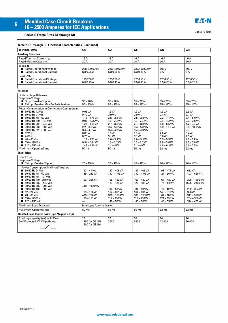
Table 2. GE through GR Electrical Characteristics (Continued)
Technical Data GE GJ GL GN GR
Conductor Cross Sections and Terminal Typesfor Main Conductors
� Solid or Stranded� Finely Stranded with End Sleeve� Bus Bar
Tightening Torque for Box TerminalsTightening Torque for Bus Bar Connection Pieces
Box Terminals
2.5 to 70 mm2
2.5 to 50/70 mm2
—5.6 Nm5.6 Nm
Box Terminals
50 to 150 mm2
35 to 120 mm2
—20 Nm15 Nm
Box Terminals
95 to 240 mm2
70 to 150 mm2
—42 Nm30 Nm
Flat BarTerminals——600 A31 Nm6 Nm
Flat Bar Terminals
——Optional31 Nm50 Nm
Flat Bar Terminals
——Optional—20 Nm
Conductor Cross Sections for Auxiliary Circuitswith Terminal Connection or Terminal Strip
� Solid � Finely Stranded with End Sleeve� With Brought-out Cable Ends� Tightening Torque for Fitting Screws
0.75 to 2.5 mm2
0.75 to 2.5 mm20.75 to 2.5 mm2
0.75 to 2.5 mm2
0.82 (AWG 18) mm2
0.8 to 1.4 Nm
0.75 to 2.5 mm2
0.75 to 2.5 mm2
0.82 (AWG 18) mm2
0.8 to 1.4 Nm
Up to 2x4 mm2
Up to 2x2.5 mm2
0.82 (AWG 18) mm2
0.8 to 1.4 Nm
Up to 2x4 mm2
Up to 2x2.5 mm2
0.82 (AWG 18) mm2
0.8 to 1.4 Nm
Power Loss per Circuit Breaker at MaximumRated Current ln (The Power Losses of theUndervoltage Releases (“r” Releases) Must BeObserved if Necessary) at Three-PhaseSymmetrical Load)
� For Plant Protection � As Isolating Circuit Breaker� For Starter Combinations� For Motor Protection
40 W40 W40 W—
45 W45 W45 W45 W
65 W65 W65 W65 W
87/210 W87/210 W——
220/270/400 W220/270/400 W——
Permissible Mounting Position
Arc Spacing —Suitable for Reverse-Feed Applications
Yes(Except HMCPE)
Yes Yes Yes Yes
90° 90° 90° 90°
PG0120002U
www.eatonelectrical.com
EE MCCB Series G PG Reprint 20/1/05 4:21 pm Page 5
January 2005
6Moulded Case Circuit Breakers16 – 2500 Amperes for IEC Applications
Series G Frame Sizes GE through GR
Table 2. GE through GR Electrical Characteristics (Continued)
Technical Data GE GJ GL GN GR
Auxiliary Switches
Rated Thermal Current lthRated Making Capacity
6 A 20 A
6 A 20 A
6 A 20 A
6 A 20 A
6 A20 A
ac (ac-15)� Rated Operational Voltage � Rated Operational Current
230/400/600 V 6/3/0.25 A
230/400/600 V 6/3/0.25 A
230/400/600 V6/3/0.25 A
600 V 6 A
600 V6 A
dc (dc-13)� Rated Operational Voltage � Rated Operational Current
125/250 V0.5/0.25 A
125/250 V0.5/0.15 A
125/250 V 0.5/0.15 A
125/250 V 0.5/0.25 A
125/250 V 0.5/0.25 A
Releases
Undervoltage ReleasesResponse Voltage:
� Drop (Breaker Tripped)� Pickup (Breaker May Be Switched on)
35 – 70% 85 – 110%
35 – 70% 85 – 110%
35 – 70% 85 – 110%
35 – 70% 85 – 110%
35 – 70% 85 – 110%
Power Consumption in Continuous Operation at:� 50/60 Hz 12Vac � 50/60 Hz 24 Vac � 50/60 Hz 48 – 60 Vac � 50/60 Hz 110 – 127 Vac � 50/60 Hz 208 – 240 Vac � 50/60 Hz 380 – 500 Vac� 50/60 Hz 525 – 600 Vac� 12Vdc � 24 Vdc � 48 – 60 Vdc � 110 – 125 Vdc � 220 – 250 Vdc
Maximum Opening Time
0.95 VA0.72 VA1.15 – 1.78 VA0.96 – 1.25 VA1.28 – 1.68 VA2.2 – 3.9 VA3.4 – 4.3 VA0.88 W0.70 W 1.12 – 1.76W0.94 – 1.21 W1.45 – 1.86 W50 ms
1.9 VA3.9 VA2.5 – 3.8 VA1.8 – 2.4 VA2.7 – 3.8 VA3.4 – 5.8 VA3.4 – 4.3 VA1.6 W 3.1 W 2.0 – 3.1 W 1.6 – 2.2 W 3.1 – 4 W 50 ms
1.9 VA3.9 VA2.5 – 3.8 VA1.8 – 2.4 VA2.7 – 3.8 VA3.4 – 5.8 VA3.4 – 4.3 VA1.6 W 3.1 W 2.0 – 3.1 W 1.6 – 2.2 W 3.1 – 4 W 50 ms
1.9 VA2.4 VA2.3 – 4.1 VA3.4 – 4.2 VA4.8 – 6.5 VA6.8 – 12.0 VA—2.6 W 3.6 W 3.5 – 5.5 W 2.9 – 3.6 W 4.8 – 6.3 W 62 ms
2.9 VA3.1 VA3.4 – 6.0 VA3.3 – 3.8 VA4.2 – 7.2 VA3.8 – 10.0 VA—3.4 W4.3 W4.8 – 7.2 W3.3 – 3.8 W6.6 – 7.5 W 62 ms
Shunt Trips
Shunt TripsResponse Voltage:
� Pickup (Breaker Tripped) 70 – 110% 70 – 110% 70 – 110% 70 – 110% 70 – 110%
Power Consumption in (Short Time) at:� 50/60 Hz 24 Vac � 50/60 Hz 48 – 60 Vac � 50/60 Hz 48 – 127 Vac � 50/60 Hz 110 – 240 Vac � 50/60 Hz 380 – 440 Vac � 50/60 Hz 380 – 600 Vac � 50/60 Hz 480 – 600 Vac � 12 – 24 Vdc � 48 – 60 Vdc � 110 – 125 Vdc � 220 – 250 Vdc
10 – 41 VA139 – 210 VA— 83 – 360 VA—418 – 1080 VA— 29 – 120 W 475 – 720 W 99 – 121 W —
87 – 405 VA710 – 1105 VA— 66 – 432 VA127 – 188 VA— 34 – 60 VA164 – 631 W 830 – 1580 W 112 – 150 W 40 – 58 W
87 – 405 VA710 – 1105 VA— 66 – 432 VA127 – 188 VA— 34 – 60 VA164 – 631 W 830 – 1580 W 112 – 150 W 40 – 58 W
98 – 475 VA 24 – 50 VA— 67 – 432 VA 76 – 110 VA— 19 – 42 VA145 – 610 W 67 – 102 W 121 – 150 W 46 – 55 W
612 VA 403 – 666 VA— 396 – 1896 VA1596 – 2156 VA— 230 – 384 VA 396 W 341 – 528 W 264 – 350 W 374 – 475 W
Maximum Load Duration Interrupts Automatically
Maximum Opening Time 50 ms 50 ms 50 ms 62 ms 62 ms
Moulded Case Switch (with High Magnetic Trip)
Breaking capacity (kA) at 415 VacSelf-Protected, Will Trip Above:
251250 for GE125;1600 for GE160
702500
706300
7012,500
7020,000
PG0120002U
www.eatonelectrical.com
EE MCCB Series G PG Reprint 20/1/05 4:21 pm Page 6
January 2005
7Moulded Case Circuit Breakers16 – 2500 Amperes for IEC Applications
Series G Frame Sizes GE through GL
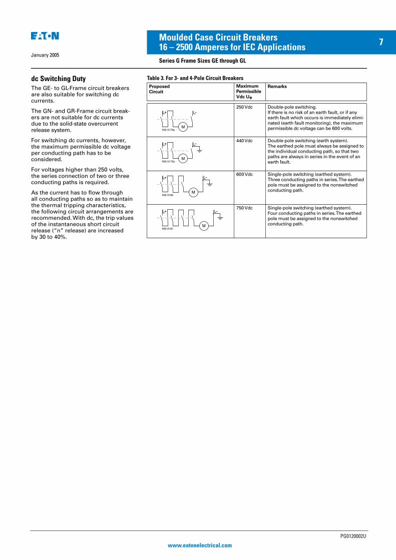
dc Switching Duty
The GE- to GL-Frame circuit breakers are also suitable for switching dc currents.
The GN- and GR-Frame circuit break-ers are not suitable for dc currents due to the solid-state overcurrent release system.
For switching dc currents, however, the maximum permissible dc voltage per conducting path has to be considered.
For voltages higher than 250 volts, the series connection of two or three conducting paths is required.
As the current has to flow through all conducting paths so as to maintain the thermal tripping characteristics, the following circuit arrangements are recommended. With dc, the trip values of the instantaneous short circuit release (“n” release) are increased by 30 to 40%.
Table 3. For 3- and 4-Pole Circuit Breakers
ProposedCircuit
Maximum PermissibleVdc Ue
Remarks
250 Vdc Double-pole switching.If there is no risk of an earth fault, or if any earth fault which occurs is immediately elimi-nated (earth fault monitoring), the maximum permissible dc voltage can be 600 volts.
440 Vdc Double-pole switching (earth system).The earthed pole must always be assigned to the individual conducting path, so that two paths are always in series in the event of an earth fault.
600 Vdc Single-pole switching (earthed system).Three conducting paths in series. The earthed pole must be assigned to the nonswitched conducting path.
750 Vdc Single-pole switching (earthed system).Four conducting paths in series. The earthed pole must be assigned to the nonswitched conducting path.
NSI-5178aM
NSI-5179aM
NSI-5180M
NSI-5181M
PG0120002U
www.eatonelectrical.com
EE MCCB Series G PG Reprint 20/1/05 4:21 pm Page 7

January 2005
8Moulded Case Circuit Breakers16 – 2500 Amperes for IEC Applications
Series G Frame Sizes GJ through GR
Multi-Function Electronic Trip Units for All Applications
Digitrip RMS Trip Units
True rms Sensing
Digitrip RMS Trip Units utilise our patented microprocessor-based intelli-gence to provide true rms sensing, permitting increased accuracy and reliable system protection. True rms sensing is not susceptible to nuisance tripping when waveforms containing high harmonic currents are present.
Digitrip RMS 310
Digitrip RMS 310 Electronic Trip Units are available with Eaton Circuit Break-ers GJ-, GL-, GN- and GR-Frames 20 through 2500 amperes. Digitrip RMS 310 Trip Units are available in four styles with either fixed or adjustable rating plugs which establishes the continuous ampere rating of the breaker.
Note: GJ- and GL-Frames have selectable long time delay (tLD) and pickup settings (Ir). A rating plug is not required.
Rating Plugs
If rating plugs are needed, they are marked for 50/60 Hz applications. Both fixed and adjustable rating plugs are available, providing further flexibility when applied to selectively coordinated systems.
Note: Digitrip RMS rating plugs are not interchangeable with Seltronic�rating plugs.
Curve Shaping
When selectively coordinated systems are called for, Digitrip RMS 310 will provide a cost-effective solution for a variety of applications.
The standard Digitrip RMS 310includes an adjustable short timepickup setting encompassing an I2t ramp function which provides the basic LS curve shaping function. GJ- and GL-Frames have an adjustable long time delay.
The optional Digitrip RMS 310 provides additional flat response short time delay adjustments on an instantaneous setting to provide LSI curve shaping capability.
Digitrip RMS 310 Trip Units are available with earth fault pickup and flat response earth fault delay which provides the trip unit with full function LSIG curve shaping flexibility.
Digitrip RMS 310 Trip Units can effec-
tively coordinate with both sophisti-cated upstream power breakers as well as downstream thermal magnetic breakers…making Digitrip RMS 310 Trip Units the cost-effective reliable choice for selectively coordinated systems.
Thermal Memory
All Digitrip RMS Trip Units incorporate a long delay. Thermal memory prevents the system from cumulative overheating due to repeated overcurrent events that may occur in quick succession.
Field Testing
A field test kit is available for Digitrip RMS 310 trip units.
Digitrip RMS 610 and 910
Digitrip RMS 610 and 910 Trip Units are available with Eaton GR-Frame Circuit Breakers 800 through 2500 amperes. Digitrip 610 and 910 Trip Units provide unparalleled system protection with the added convenience of a local display.
Curve Shaping
Digitrip RMS 610 and 910 Trip Units are available with up to nine curve shaping choices achieved by adjusting up to seven switches on the front of the unit for optimum system coordination. Maximum curve shaping flexibility is provided by dependent long and short delay adjustments that are long delay pickup (Ir) based, depicted on the front of the unit by the blue portion of the time-current curve.
Additional coordination capability can be provided by utilising the short delay and earth fault zone selective interlocking features available on these trip units.
System Diagnostics
Digitrip RMS 610 and 910 models of trip units provide long delay, short delay, instantaneous, and earth fault cause of trip LEDs on the front of the unit. Their display shows a magnitude of trip information, as well as remote signal contacts, for improved system alarming.
System Monitoring
Digitrip 610 and 910 Trip Units have the capability to monitor phase currents, as well as neutral or ground currents. This information is displayed on a large digital display mounted on the unit.
Digitrip RMS 910 Trip Units can also provide the user with power and energy monitoring capability. Peak power demand, present power demand, and total energy, as well as forward and reverse energy can be monitored with this unit.
Digitrip RMS 910 Trip Units have the additional capability of monitoring line-to-line voltage, as well as system power factor. Both parameters are dis-played in the digital display window and are supported by LEDs to indicate which parameter is being displayed.
Harmonics Monitoring
Digitrip RMS 910 Trip Units are capable of displaying values of current harmonics in the digital display win-dow. Percentage of harmonic content can be monitored for each phase, up to the 27th harmonic. Additionally, a total harmonic distortion value can be calculated and displayed.
Communications
Digitrip RMS 910 units have built-in communications options to allow all protection, monitoring, and control information to be transmitted back to a central location via the PowerNet�system.
Field Testing
Integral field testing capability is provided on all 610 and 910 Trip Units. No additional test set is needed to per-form both trip and no trip field testing.
RMS 610 RMS 910
PG0120002U
www.eatonelectrical.com
EE MCCB Series G PG Reprint 20/1/05 4:21 pm Page 8
January 2005
9Moulded Case Circuit Breakers16 – 2500 Amperes for IEC Applications
Series G Frame Sizes GJ through GR
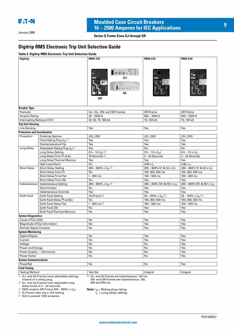
Digitrip RMS Electronic Trip Unit Selection Guide
Table 4. Digitrip RMS Electronic Trip Unit Selection Guide
� GJ- and GL-Frames have selectable settings instead of a rating plug.
� GJ- and GL-Frames have adjustable long delay times of 2 – 24 seconds.
� 2500 ampere GR-Frame 200 – 600% x (In).� GJ-Frame also has a 14X setting.� Not to exceed 1250 amperes.
� GJ- and GL-Frames are Instantaneous, 120 ms.GN- and GR-Frames are Instantaneous, 100,300 and 500 ms.
Note: In = Rating plug rating.Ir = Long delay setting.
Digitrip RMS 310 RMS 610 RMS 910
Breaker Type
Frame(s) GJ-, GL-, GN- and GR-Frames GR-Frame GR-Frame
Ampere Rating 20 – 2500 A 800 – 2500 A 800 – 2500 A
Interrupting Rating at 415 V 40, 50, 70, 100 kA 70, 100 kA 70, 100 kA
Trip Unit Sensing
rms Sensing Yes Yes Yes
Protection and Coordination
Protection Ordering Options LSI, LSIG LSI, LSIG LSI, LSIG
Fixed Rating Plug (In) � Yes Yes Yes
Overtemperature Trip Yes Yes Yes
Long Delay Adjustable Rating Plug (ln) � Yes No No
Long Delay Setting 0.5 – 1.0 (ln) � 0.5 – 1.0 x (ln) 0.5 – 1.0 x (ln)
Long Delay Time I2t at 6x 10 Seconds � 2 – 24 Seconds 2 – 24 Seconds
Long Delay Thermal Memory Yes Yes Yes
High Load Alarm No 0.85 x Ir 0.85 x IrShort Delay Short Delay Setting 200 – 800% x (ln) � 200 – 600% S1 & S2 x (Ir) 200 – 600% S1 & S2 x (Ir)
Short Delay Time I2t No 100, 300, 500 ms 100, 300, 500 ms
Short Delay Time Flat I – 300 ms 100 – 500 ms 100 – 500 ms
Short Delay Time ZSI No Yes Yes
Instantaneous Instantaneous Setting 200 – 800% x (ln) � 200 – 600% M1 & M2 x (ln) 200 – 600% M1 & M2 x (ln)
Discriminator No Yes Yes
Instantaneous Override Yes Yes Yes
Earth Fault Earth Fault Setting Var/Frame � 25 – 100% x (ln) � 25 – 100% x (ln) �
Earth Fault Delay I2t at.62x No 100, 300, 500 ms 100, 300, 500 ms
Earth Fault Delay Flat I – 500 ms � 100 – 500 ms 100 – 500 ms
Earth Fault ZSI No Yes Yes
Earth Fault Thermal Memory No Yes Yes
System Diagnostics
Cause of Trip LEDs No Yes Yes
Magnitude of Trip Information No Yes Yes
Remote Signal Contacts No Yes Yes
System Monitoring
Digital Display No Yes Yes
Current No Yes Yes
Voltage No No Yes
Power and Energy No No Yes
Power Quality — Harmonics No No Yes
Power Factor No No Yes
System Communications
PowerNet No No Yes
Field Testing
Testing Method Test Set Integral Integral
GR
GJ
GL
PG0120002U
www.eatonelectrical.com
EE MCCB Series G PG Reprint 20/1/05 4:21 pm Page 9

January 2005
10 Moulded Case Circuit Breakers16 – 2500 Amperes for IEC Applications
PG0120002U
www.eatonelectrical.com
EE MCCB Series G PG Reprint 20/1/05 4:21 pm Page 10
January 2005
11Moulded Case Circuit Breakers16 – 2500 Amperes for IEC Applications
Series G Frame Size GE, 160 Amperes
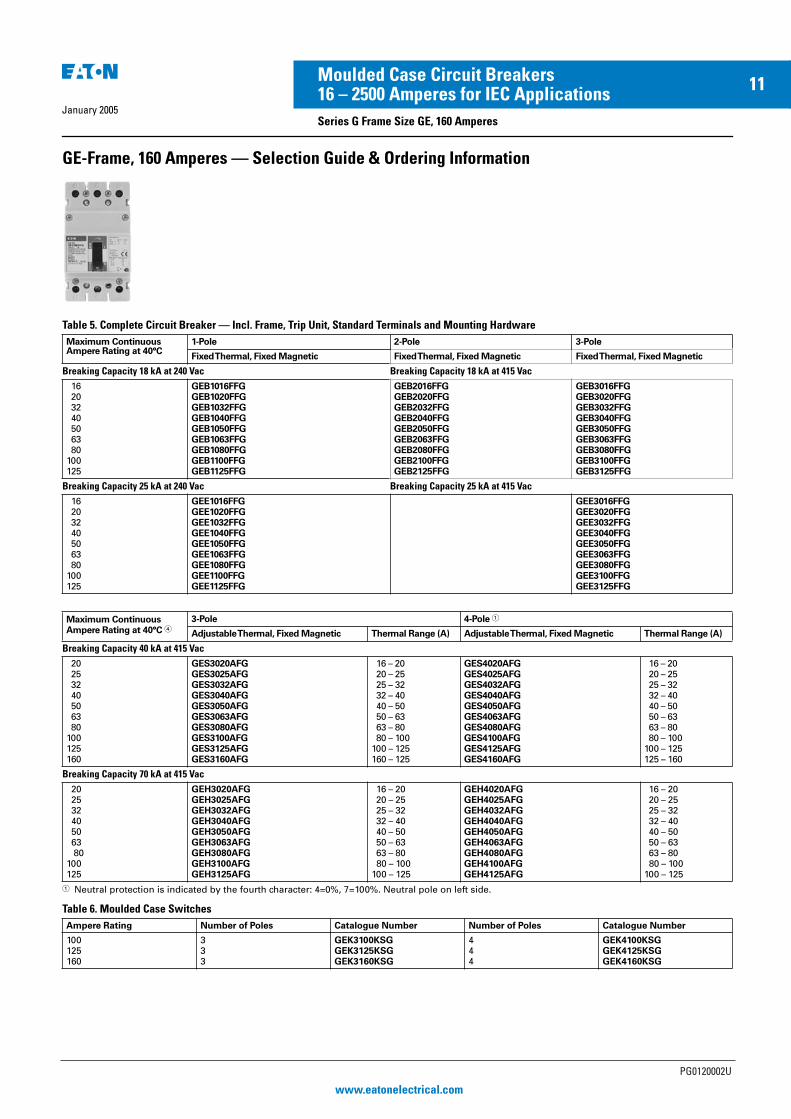
GE-Frame, 160 Amperes — Selection Guide & Ordering Information
Table 5. Complete Circuit Breaker — Incl. Frame, Trip Unit, Standard Terminals and Mounting Hardware
� Neutral protection is indicated by the fourth character: 4=0%, 7=100%. Neutral pole on left side.
Table 6. Moulded Case Switches
Maximum ContinuousAmpere Rating at 40°C
1-Pole 2-Pole 3-Pole
Fixed Thermal, Fixed Magnetic Fixed Thermal, Fixed Magnetic Fixed Thermal, Fixed Magnetic
Breaking Capacity 18 kA at 240 Vac Breaking Capacity 18 kA at 415 Vac
16 20 32 40 50 63 80100125
GEB1016FFGGEB1020FFGGEB1032FFGGEB1040FFGGEB1050FFGGEB1063FFGGEB1080FFGGEB1100FFGGEB1125FFG
GEB2016FFGGEB2020FFGGEB2032FFGGEB2040FFGGEB2050FFGGEB2063FFGGEB2080FFGGEB2100FFGGEB2125FFG
GEB3016FFGGEB3020FFGGEB3032FFGGEB3040FFGGEB3050FFGGEB3063FFGGEB3080FFGGEB3100FFGGEB3125FFG
Breaking Capacity 25 kA at 240 Vac Breaking Capacity 25 kA at 415 Vac
16 20 32 40 50 63 80100125
GEE1016FFGGEE1020FFGGEE1032FFGGEE1040FFGGEE1050FFGGEE1063FFGGEE1080FFGGEE1100FFGGEE1125FFG
GEE3016FFGGEE3020FFGGEE3032FFGGEE3040FFGGEE3050FFGGEE3063FFGGEE3080FFGGEE3100FFGGEE3125FFG
Maximum ContinuousAmpere Rating at 40°C �
3-Pole 4-Pole �
Adjustable Thermal, Fixed Magnetic Thermal Range (A) Adjustable Thermal, Fixed Magnetic Thermal Range (A)
Breaking Capacity 40 kA at 415 Vac
20 25 32 40 50 63 80100125160
GES3020AFGGES3025AFGGES3032AFGGES3040AFGGES3050AFGGES3063AFGGES3080AFGGES3100AFGGES3125AFGGES3160AFG
16 – 20 20 – 25 25 – 32 32 – 40 40 – 50 50 – 63 63 – 80 80 – 100100 – 125160 – 125
GES4020AFGGES4025AFGGES4032AFGGES4040AFGGES4050AFGGES4063AFGGES4080AFGGES4100AFGGES4125AFGGES4160AFG
16 – 20 20 – 25 25 – 32 32 – 40 40 – 50 50 – 63 63 – 80 80 – 100100 – 125125 – 160
Breaking Capacity 70 kA at 415 Vac
20 25 32 40 50 63 80100125
GEH3020AFGGEH3025AFGGEH3032AFGGEH3040AFGGEH3050AFGGEH3063AFGGEH3080AFGGEH3100AFGGEH3125AFG
16 – 20 20 – 25 25 – 32 32 – 40 40 – 50 50 – 63 63 – 80 80 – 100100 – 125
GEH4020AFGGEH4025AFGGEH4032AFGGEH4040AFGGEH4050AFGGEH4063AFGGEH4080AFGGEH4100AFGGEH4125AFG
16 – 20 20 – 25 25 – 32 32 – 40 40 – 50 50 – 63 63 – 80 80 – 100100 – 125
Ampere Rating Number of Poles Catalogue Number Number of Poles Catalogue Number
100125160
333
GEK3100KSGGEK3125KSGGEK3160KSG
444
GEK4100KSGGEK4125KSGGEK4160KSG
PG0120002U
www.eatonelectrical.com
EE MCCB Series G PG Reprint 20/1/05 4:21 pm Page 11
January 2005
12Moulded Case Circuit Breakers16 – 2500 Amperes for IEC Applications
Series G Frame Size GE, 160 Amperes
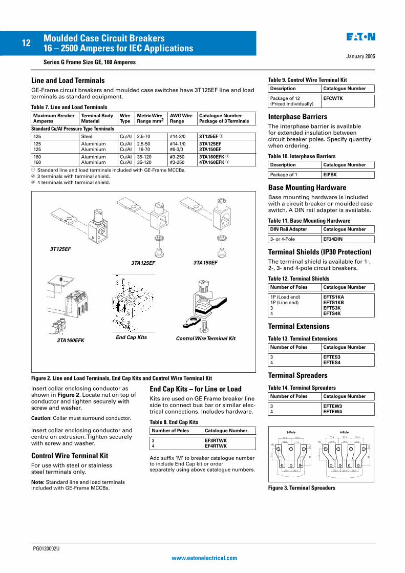
Line and Load Terminals
GE-Frame circuit breakers and moulded case switches have 3T125EF line and load terminals as standard equipment.
Table 7. Line and Load Terminals
� Standard line and load terminals included with GE-Frame MCCBs.� 3 terminals with terminal shield.� 4 terminals with terminal shield.
Figure 2. Line and Load Terminals, End Cap Kits and Control Wire Terminal Kit
Insert collar enclosing conductor as shown in Figure 2. Locate nut on top of conductor and tighten securely with screw and washer.
Caution: Collar must surround conductor.
Insert collar enclosing conductor and centre on extrusion. Tighten securely with screw and washer.
Control Wire Terminal Kit
For use with steel or stainless steel terminals only.
Note: Standard line and load terminals included with GE-Frame MCCBs.
End Cap Kits – for Line or Load
Kits are used on GE Frame breaker line side to connect bus bar or similar elec-trical connections. Includes hardware.
Table 8. End Cap Kits
Add suffix ‘M’ to breaker catalogue number to include End Cap kit or order separately using above catalogue numbers.
Maximum BreakerAmperes
Terminal BodyMaterial
WireType
Metric WireRange mm2
AWG WireRange
Catalogue NumberPackage of 3 Terminals
Standard Cu/Al Pressure Type Terminals
125 Steel Cu/Al 2.5-70 #14-3/0 3T125EF �
125125
AluminiumAluminium
Cu/AlCu/Al
2.5-50 16-70
#14-1/0#6-3/0
3TA125EF3TA150EF
160160
AluminiumAluminium
Cu/AlCu/Al
35-12035-120
#3-250#3-250
3TA160EFK �
4TA160EFK �
3T125EF
3TA125EF 3TA150EF
3TA160EFKEnd Cap Kits Control Wire Terminal Kit
Number of Poles Catalogue Number
34
EF3RTWKEF4RTWK
Table 9. Control Wire Terminal Kit
Interphase Barriers
The interphase barrier is available for extended insulation between circuit breaker poles. Specify quantity when ordering.
Table 10. Interphase Barriers
Base Mounting Hardware
Base mounting hardware is included with a circuit breaker or moulded case switch. A DIN rail adapter is available.
Table 11. Base Mounting Hardware
Terminal Shields (IP30 Protection)
The terminal shield is available for 1-, 2-, 3- and 4-pole circuit breakers.
Table 12. Terminal Shields
Terminal Extensions
Table 13. Terminal Extensions
Terminal Spreaders
Table 14. Terminal Spreaders
Figure 3. Terminal Spreaders
Description Catalogue Number
Package of 12(Priced Individually)
EFCWTK
Description Catalogue Number
Package of 1 EIPBK
DIN Rail Adapter Catalogue Number
3- or 4-Pole EF34DIN
Number of Poles Catalogue Number
1P (Load end)1P (Line end)34
EFTS1KAEFTS1KBEFTS3KEFTS4K
Number of Poles Catalogue Number
34
EFTES3EFTES4
Number of Poles Catalogue Number
34
EFTEW3EFTEW4
PG0120002U
www.eatonelectrical.com
EE MCCB Series G PG Reprint 20/1/05 4:21 pm Page 12
13Moulded Case Circuit Breakers
January 200516 – 2500 Amperes for IEC Applications
Series G Frame Size GJ, 250 Amperes
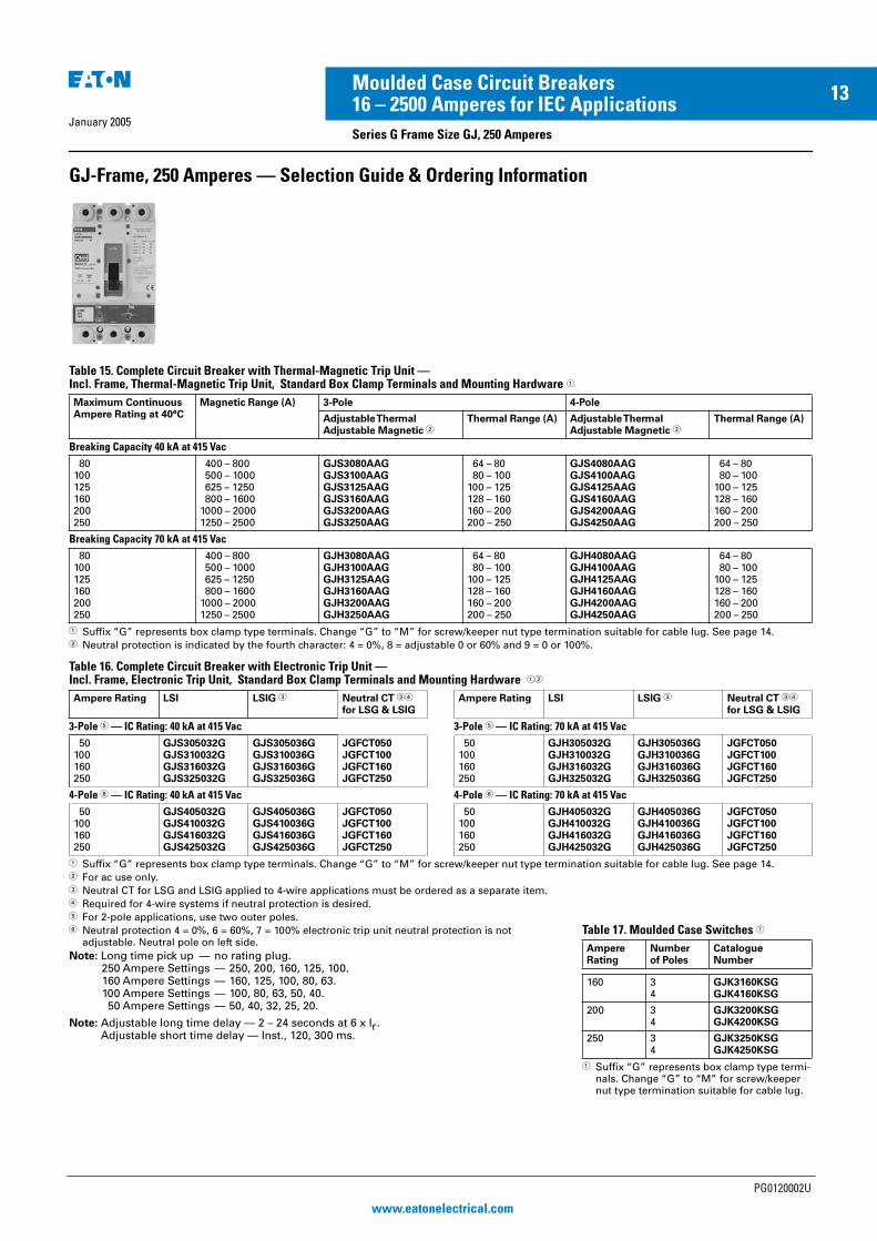
GJ-Frame, 250 Amperes — Selection Guide & Ordering Information
Table 15. Complete Circuit Breaker with Thermal-Magnetic Trip Unit — Incl. Frame, Thermal-Magnetic Trip Unit, Standard Box Clamp Terminals and Mounting Hardware �
� Suffix “G” represents box clamp type terminals. Change “G” to “M” for screw/keeper nut type termination suitable for cable lug. See page 14.� Neutral protection is indicated by the fourth character: 4 = 0%, 8 = adjustable 0 or 60% and 9 = 0 or 100%.
Table 16. Complete Circuit Breaker with Electronic Trip Unit — Incl. Frame, Electronic Trip Unit, Standard Box Clamp Terminals and Mounting Hardware ��
� Suffix “G” represents box clamp type terminals. Change “G” to “M” for screw/keeper nut type termination suitable for cable lug. See page 14.� For ac use only.� Neutral CT for LSG and LSIG applied to 4-wire applications must be ordered as a separate item.� Required for 4-wire systems if neutral protection is desired.� For 2-pole applications, use two outer poles.� Neutral protection 4 = 0%, 6 = 60%, 7 = 100% electronic trip unit neutral protection is not
adjustable. Neutral pole on left side.
Note: Long time pick up — no rating plug.250 Ampere Settings — 250, 200, 160, 125, 100.160 Ampere Settings — 160, 125, 100, 80, 63.100 Ampere Settings — 100, 80, 63, 50, 40. 50 Ampere Settings — 50, 40, 32, 25, 20.
Note: Adjustable long time delay — 2 – 24 seconds at 6 x Ir.Adjustable short time delay — Inst., 120, 300 ms.
Maximum ContinuousAmpere Rating at 40°C
Magnetic Range (A) 3-Pole 4-Pole
Adjustable ThermalAdjustable Magnetic �
Thermal Range (A) Adjustable ThermalAdjustable Magnetic �
Thermal Range (A)
Breaking Capacity 40 kA at 415 Vac
80100125160200250
400 – 800 500 – 1000 625 – 1250 800 – 16001000 – 20001250 – 2500
GJS3080AAGGJS3100AAGGJS3125AAGGJS3160AAGGJS3200AAGGJS3250AAG
64 – 80 80 – 100100 – 125128 – 160160 – 200200 – 250
GJS4080AAGGJS4100AAGGJS4125AAGGJS4160AAGGJS4200AAGGJS4250AAG
64 – 80 80 – 100100 – 125128 – 160160 – 200200 – 250
Breaking Capacity 70 kA at 415 Vac
80100125160200250
400 – 800 500 – 1000 625 – 1250 800 – 16001000 – 20001250 – 2500
GJH3080AAGGJH3100AAGGJH3125AAGGJH3160AAGGJH3200AAGGJH3250AAG
64 – 80 80 – 100100 – 125128 – 160160 – 200200 – 250
GJH4080AAGGJH4100AAGGJH4125AAGGJH4160AAGGJH4200AAGGJH4250AAG
64 – 80 80 – 100100 – 125128 – 160160 – 200200 – 250
Ampere Rating LSI LSIG � Neutral CT ��
for LSG & LSIGAmpere Rating LSI LSIG � Neutral CT ��
for LSG & LSIG
3-Pole � — IC Rating: 40 kA at 415 Vac 3-Pole � — IC Rating: 70 kA at 415 Vac
50100160250
GJS305032GGJS310032GGJS316032GGJS325032G
GJS305036GGJS310036GGJS316036GGJS325036G
JGFCT050JGFCT100JGFCT160JGFCT250
50100160250
GJH305032GGJH310032GGJH316032GGJH325032G
GJH305036GGJH310036GGJH316036GGJH325036G
JGFCT050JGFCT100JGFCT160JGFCT250
4-Pole � — IC Rating: 40 kA at 415 Vac 4-Pole � — IC Rating: 70 kA at 415 Vac
50100160250
GJS405032GGJS410032GGJS416032GGJS425032G
GJS405036GGJS410036GGJS416036GGJS425036G
JGFCT050JGFCT100JGFCT160JGFCT250
50100160250
GJH405032GGJH410032GGJH416032GGJH425032G
GJH405036GGJH410036GGJH416036GGJH425036G
JGFCT050JGFCT100JGFCT160JGFCT250
Table 17. Moulded Case Switches �
� Suffix “G” represents box clamp type termi-nals. Change “G” to “M” for screw/keeper nut type termination suitable for cable lug.
AmpereRating
Numberof Poles
CatalogueNumber
160 34
GJK3160KSGGJK4160KSG
200 34
GJK3200KSGGJK4200KSG
250 34
GJK3250KSGGJK4250KSG
PG0120002U
www.eatonelectrical.com
EE MCCB Series G PG Reprint 20/1/05 4:21 pm Page 13
January 2005
14Moulded Case Circuit Breakers16 – 2500 Amperes for IEC Applications
Series G Frame Size GJ, 250 Amperes
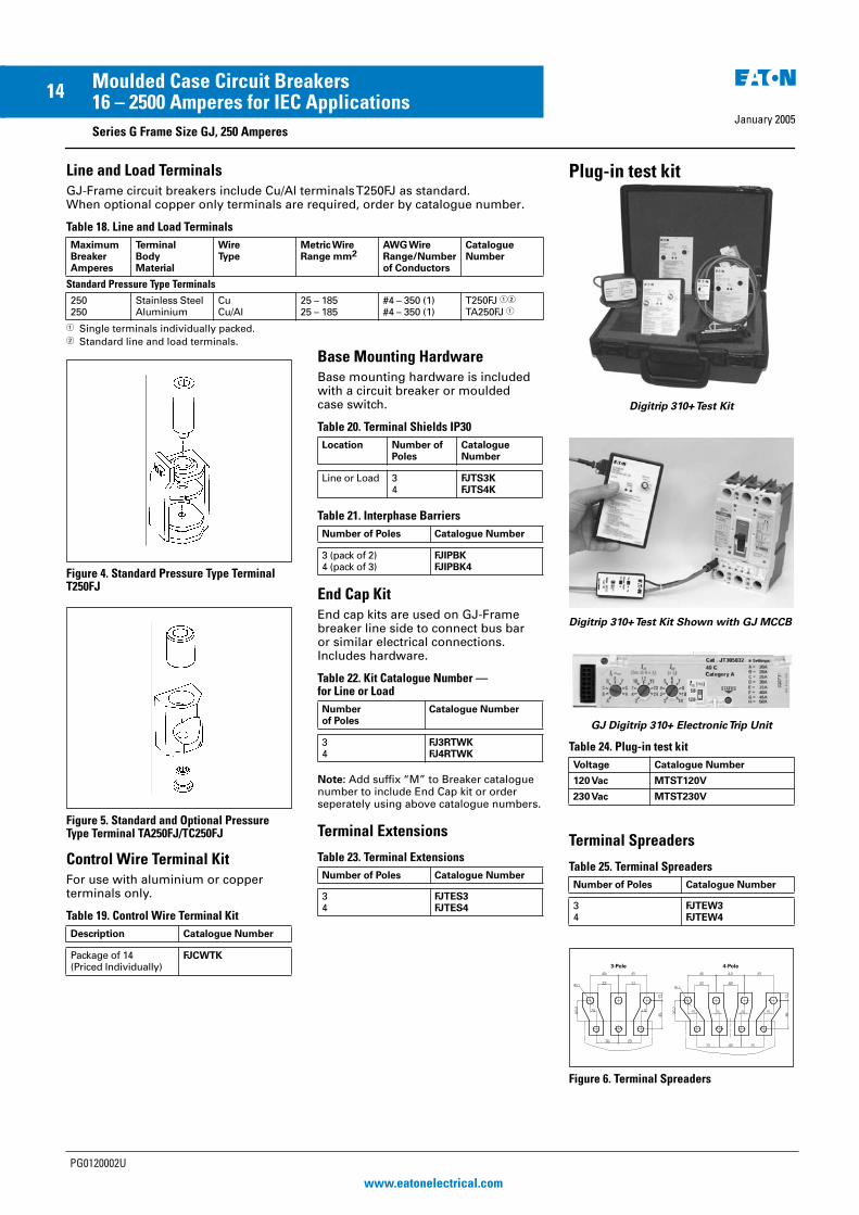
Line and Load Terminals
GJ-Frame circuit breakers include Cu/Al terminals T250FJ as standard. When optional copper only terminals are required, order by catalogue number.
Table 18. Line and Load Terminals
� Single terminals individually packed.� Standard line and load terminals.
Figure 4. Standard Pressure Type Terminal T250FJ
Figure 5. Standard and Optional Pressure Type Terminal TA250FJ/TC250FJ
Control Wire Terminal Kit
For use with aluminium or copper terminals only.
Table 19. Control Wire Terminal Kit
Base Mounting Hardware
Base mounting hardware is included with a circuit breaker or moulded case switch.
Table 20. Terminal Shields IP30
Table 21. Interphase Barriers
End Cap Kit
End cap kits are used on GJ-Frame breaker line side to connect bus bar or similar electrical connections. Includes hardware.
Table 22. Kit Catalogue Number — for Line or Load
Note: Add suffix “M” to Breaker catalogue number to include End Cap kit or order seperately using above catalogue numbers.
Terminal Extensions
Table 23. Terminal Extensions
MaximumBreakerAmperes
TerminalBodyMaterial
WireType
Metric WireRange mm2
AWG WireRange/Numberof Conductors
CatalogueNumber
Standard Pressure Type Terminals
250250
Stainless SteelAluminium
CuCu/Al
25 – 18525 – 185
#4 – 350 (1)#4 – 350 (1)
T250FJ ��
TA250FJ �
Description Catalogue Number
Package of 14(Priced Individually)
FJCWTK
Location Number of Poles
Catalogue Number
Line or Load 34
FJTS3KFJTS4K
Number of Poles Catalogue Number
3 (pack of 2)4 (pack of 3)
FJIPBKFJIPBK4
Number of Poles
Catalogue Number
34
FJ3RTWKFJ4RTWK
Number of Poles Catalogue Number
34
FJTES3FJTES4
Plug-in test kit
Digitrip 310+ Test Kit
Digitrip 310+ Test Kit Shown with GJ MCCB
GJ Digitrip 310+ Electronic Trip Unit
Table 24. Plug-in test kit
Terminal Spreaders
Table 25. Terminal Spreaders
Figure 6. Terminal Spreaders
Voltage Catalogue Number
120 Vac MTST120V
230 Vac MTST230V
Number of Poles Catalogue Number
34
FJTEW3FJTEW4
PG0120002U
www.eatonelectrical.com
EE MCCB Series G PG Reprint 20/1/05 4:21 pm Page 14

January 2005
15Moulded Case Circuit Breakers16 – 2500 Amperes for IEC Applications
Series G Frame Size GL, 630 Amperes
Table 26. Complete Circuit Breaker — Incl. Frame, Thermal Magnetic Trip Unit, Standard Box Clamp Terminals & Mounting Hardware �
� Suffix “G” represents box clamp type terminals. Change “G” to “M” for screw/keeper nut type termination suitable for cable lug. See page 16.
� For 2-pole applications, use two outer poles.� Neutral protection is indicated by the fourth character: 4 = 0%, 7 = 100%, 8 = adjustable 0 – 60%
and 9 = 0 – 100%.
Table 27. Complete Circuit Breaker with Electronic Trip Unit — Incl. Frame, Electronic Trip Unit, Standard Box Clamp Terminals & Mounting Hardware ��
� Suffix “G” represents box clamp type terminals. Change “G” to “M” for screw/keeper nut type termination suitable for cable lug. See page 16.
� For ac use only.� Neutral CT for LSG and LSIG applied to 4-wire applications must be ordered as a separate item.� Required for 4-wire systems if neutral protection is desired.� For 2-pole applications, use two outer poles.� Neutral protection 4 = 0%, 6 = 60%, 7 = 100% electronic trip unit neutral protection is not
adjustable. Neutral pole on left side.
Maximum Continuous AmpereRating at 40°C
Magnetic Range (A)
3-Pole � Thermal Range (A)
4-Pole (0%) � Thermal Range (A)Adj. Thermal
Adj. MagneticAdj. ThermalAdj. Magnetic
Breaking Capacity 50 kA at 415 Vac
250320
1250-25001600-3200
GLS3250AAGGLS3320AAG
200-250250-320
GLS4250AAGGLS4320AAG
200-250250-320
400500630
2000-40002500-50003150-6300
GLS3400AAGGLS3500AAGGLS3630AAG
320-400400-500500-630
GLS4400AAGGLS4500AAGGLS4630AAG
320-400400-500500-630
Breaking Capacity 70 kA at 415 Vac
250320
1250-20001600-3200
GLH3250AAGGLH3320AAG
200-250250-320
GLH4250AAGGLH4320AAG
200-250250-320
400500630
2000-40002500-50003150-6300
GLH3400AAGGLH3500AAGGLH3630AAG
320-400400-500500-630
GLH4400AAGGLH4500AAGGLH4630AAG
320-400400-500500-630
Maximum Continuous AmpereRating at 40°C
LSI LSIG Neutral CTfor LSG & LSIG ��
3-Pole � — Breaking Capacity 50 kA at 415 Vac
250400630 �
GLS325032GGLS340032GGLS363032G
GLS325036GGLS340036GGLS363036G
LGFCT250LGFCT400LGFCT630
4-Pole � — Breaking Capacity 50 kA at 415 Vac
250400630 �
GLS425032GGLS440032GGLS463032G
GLS425036GGLS440036GGLS463036G
LGFCT250LGFCT400LGFCT630
3-Pole � — Breaking Capacity 70 kA at 415 Vac
250400630 �
GLH325032GGLH340032GGLH363032G
GLH325036GGLH340036GGLH363036G
LGFCT250LGFCT400LGFCT630
4-Pole � — Breaking Capacity 70 kA at 415 Vac
250400630 �
GLH425032GGLH440032GGLH463032G
GLH425036GGLH440036GGLH463036G
LGFCT250LGFCT400LGFCT630
Table 28. Moulded Case Switches
Plug-in test kit
Digitrip 310+ Test Kit
Table 29. Plug-in test kit
Note: Long time pick up—no rating plug needed.630 Ampere Settings—630, 600, 500, 400, 350, 315, 300, 250 (315, 630 are IEC ratings only).400 Ampere Settings—400, 350, 315, 300, 250, 225, 200, 160 (315 is IEC rating only).250 Ampere Settings—250, 225, 200, 175, 160, 150, 125, 100 (160 is IEC rat-ing only).
Note: Adjustable long time delay — 2 – 24 seconds at 6 x Ir.Adjustable short time delay — Inst., 120, 300 ms.
AmpereRating
Numberof Poles
CatalogueNumber �
250 34
GLK3250KSGGLK4250KSG
320 34
GLK3320KSGGLK4320KSG
400 34
GLK3400KSGGLK4400KSG
630 34
GLK3630KSGGLK4630KSG
Voltage Catalogue Number
120 Vac MTST120V
230 Vac MTST230V
GL-Frame, 630 Amperes — Selection Guide & Ordering Information
PG0120002U
www.eatonelectrical.com
EE MCCB Series G PG Reprint 20/1/05 4:21 pm Page 15
January 2005
16Moulded Case Circuit Breakers16 – 2500 Amperes for IEC Applications
Series G Frame Size GL, 630 Amperes
Line and Load Terminals
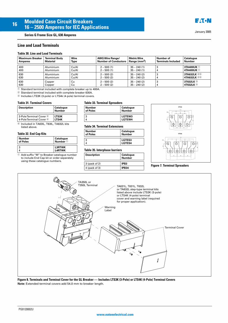
Table 30. Line and Load Terminals
� Standard terminal included with complete breaker up to 400A.� Standard terminal included with complete breaker 630A.� Includes LTS3K (3-pole) or LTS4k (4-pole) terminal covers.
Table 31. Terminal Covers
� Included in TA63IL, T63IL, TA632L kits listed above.
Table 32. End Cap Kits
� Add suffix “M” to Breaker catalogue number to include End Cap kit or order separately using these catalogue numbers.
Table 33. Terminal Spreaders
Table 34. Terminal Extensions
Table 35. Interphase barriers
Figure 7. Terminal Spreaders
Figure 8. Terminals and Terminal Cover for the GL Breaker — Includes LTS3K (3-Pole) or LTS4K (4-Pole) Terminal Covers
Note: Extended terminal covers add 54.0 mm to breaker length.
Maximum BreakerAmperes
Terminal BodyMaterial
WireType
AWG Wire Range/Number of Conductors
Metric WireRange (mm2)
Number of Terminals Included
CatalogueNumber
400400
AluminiumAluminium
Cu/AlCu/Al
2 – 500 (1) 2 – 500 (1)
35 – 240 (1)35 – 240 (1)
34
3TA400UK �
4TA400UK �
630630
AluminiumAluminium
Cu/AlCu/Al
2 – 500 (2) 2 – 500 (2)
35 – 240 (2)35 – 240 (2)
34
3TA632LK ��
4TA632LK ��
630630
CopperCopper
CuCu
2 – 500 (2) 2 – 500 (2)
35 – 240 (2)35 – 240 (2)
34
3T632LK �
4T632LK �
Description CatalogueNumber
3-Pole Terminal Cover �
4-Pole Terminal Cover �LTS3KLTS4K
Numberof Poles
CatalogueNumber �
34
L3RTWKL4RTWK
Numberof Poles
CatalogueNumber
34
LGTEW3LGTEW4
Numberof Poles
CatalogueNumber
34
LGTES3LGTES4
Description CatalogueNumber
3 (pack of 2) IPB3
4 (pack of 3) IPB34
Warning Label
TA350L or T350L Terminal TA631L, T631L, T632L
or TA632L step-type terminal kitslisted above include LTS3K (3-pole)or LTS4K (4-pole) terminal cover and warning label (requiredfor proper application).
Terminal Cover
PG0120002U
www.eatonelectrical.com
EE MCCB Series G PG Reprint 20/1/05 4:21 pm Page 16
17Moulded Case Circuit Breakers
January 200516 – 2500 Amperes for IEC Applications
Series G Frame Size GN, 1250 Amperes 50 kA at 415 Vac
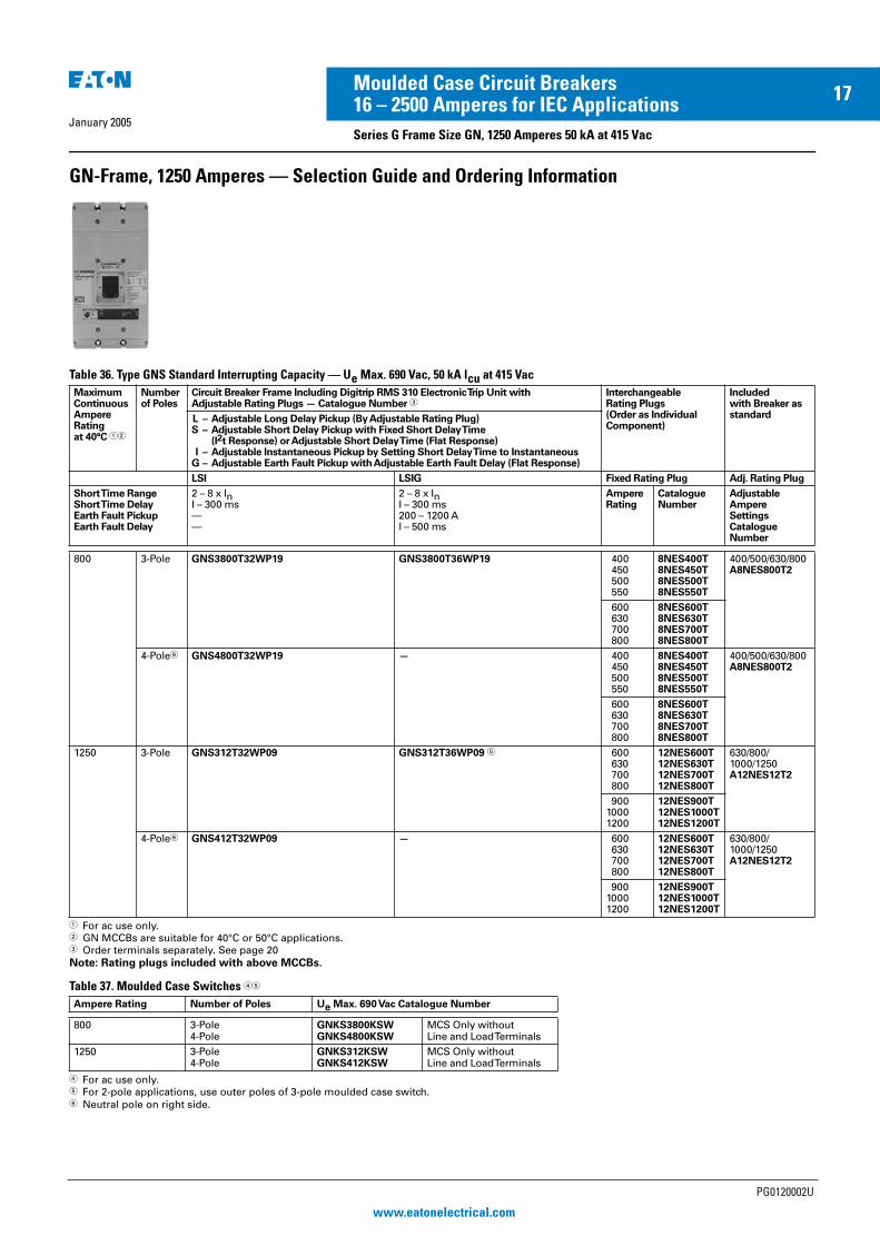
GN-Frame, 1250 Amperes — Selection Guide and Ordering Information
Table 36. Type GNS Standard Interrupting Capacity — Ue Max. 690 Vac, 50 kA lcu at 415 Vac
� For ac use only.� GN MCCBs are suitable for 40°C or 50°C applications.� Order terminals separately. See page 20
Note: Rating plugs included with above MCCBs.
Table 37. Moulded Case Switches ��
� For ac use only.� For 2-pole applications, use outer poles of 3-pole moulded case switch.� Neutral pole on right side.
Maximum Continuous Ampere Rating at 40°C ��
Number of Poles
Circuit Breaker Frame Including Digitrip RMS 310 Electronic Trip Unit withAdjustable Rating Plugs — Catalogue Number �
Interchangeable Rating Plugs(Order as Individual Component)
Includedwith Breaker as standardL – Adjustable Long Delay Pickup (By Adjustable Rating Plug)
S – Adjustable Short Delay Pickup with Fixed Short Delay Time(I2t Response) or Adjustable Short Delay Time (Flat Response)
I – Adjustable Instantaneous Pickup by Setting Short Delay Time to InstantaneousG – Adjustable Earth Fault Pickup with Adjustable Earth Fault Delay (Flat Response)
LSI LSIG Fixed Rating Plug Adj. Rating Plug
Short Time RangeShort Time DelayEarth Fault PickupEarth Fault Delay
2 – 8 x InI – 300 ms——
2 – 8 x InI – 300 ms200 – 1200 AI – 500 ms
Ampere Rating
CatalogueNumber
AdjustableAmpereSettingsCatalogue Number
800 3-Pole GNS3800T32WP19 GNS3800T36WP19 400 450 500 550
8NES400T8NES450T8NES500T8NES550T
400/500/630/800A8NES800T2
600 630 700 800
8NES600T8NES630T8NES700T8NES800T
4-Pole� GNS4800T32WP19 — 400 450 500 550
8NES400T8NES450T8NES500T8NES550T
400/500/630/800A8NES800T2
600 630 700 800
8NES600T8NES630T8NES700T8NES800T
1250 3-Pole GNS312T32WP09 GNS312T36WP09 � 600 630 700 800
12NES600T12NES630T12NES700T12NES800T
630/800/1000/1250A12NES12T2
90010001200
12NES900T12NES1000T12NES1200T
4-Pole� GNS412T32WP09 — 600 630 700 800
12NES600T12NES630T12NES700T12NES800T
630/800/1000/1250A12NES12T2
90010001200
12NES900T12NES1000T12NES1200T
Ampere Rating Number of Poles Ue Max. 690 Vac Catalogue Number
800 3-Pole4-Pole
GNKS3800KSWGNKS4800KSW
MCS Only withoutLine and Load Terminals
1250 3-Pole4-Pole
GNKS312KSWGNKS412KSW
MCS Only withoutLine and Load Terminals
PG0120002U
www.eatonelectrical.com
EE MCCB Series G PG Reprint 20/1/05 4:21 pm Page 17
January 2005
18Moulded Case Circuit Breakers16 – 2500 Amperes for IEC Applications
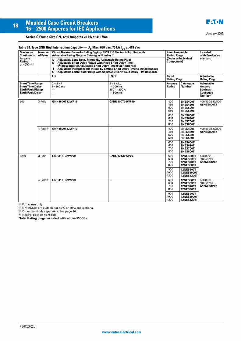
Series G Frame Size GN, 1250 Amperes 70 kA at 415 Vac
Table 38. Type GNH High Interrupting Capacity — Ue Max. 690 Vac, 70 kA Icu at 415 Vac
� For ac use only.� GN MCCBs are suitable for 40°C or 50°C applications.� Order terminals separately. See page 20.� Neutral pole on right side.Note: Rating plugs included with above MCCBs.
Maximum Continuous Ampere Rating at 40°C ��
Number of Poles
Circuit Breaker Frame Including Digitrip RMS 310 Electronic Trip Unit withAdjustable Rating Plugs — Catalogue Number �
InterchangeableRating Plugs(Order as IndividualComponent)
Includedwith Breaker as standardL – Adjustable Long Delay Pickup (By Adjustable Rating Plug)
S – Adjustable Short Delay Pickup with Fixed Short Delay Time(I2t Response) or Adjustable Short Delay Time (Flat Response)
I – Adjustable Instantaneous Pickup by Setting Short Delay Time to InstantaneousG – Adjustable Earth Fault Pickup with Adjustable Earth Fault Delay (Flat Response)
LSI LSIG FixedRating Plug
AdjustableRating Plug
Short Time RangeShort Time DelayEarth Fault PickupEarth Fault Delay
2 – 8 x InI – 300 ms——
2 – 8 x InI – 300 ms200 – 1200 AI – 500 ms
Ampere Rating
CatalogueNumber
AdjustableAmpereSettingsCatalogue Number
800 3-Pole GNH3800T32WP19 GNH3800T36WP19 400 450 500 550
8NES400T8NES450T8NES500T8NES550T
400/500/630/800A8NES800T2
600 630 700 800
8NES600T8NES630T8NES700T8NES800T
4-Pole� GNH4800T32WP19 — 400 450 500 550
8NES400T8NES450T8NES500T8NES550T
400/500/630/800A8NES800T2
600 630 700 800
8NES600T8NES630T8NES700T8NES800T
1250 3-Pole GNH312T32WP09 GNH312T36WP09 600 630 700 800
12NES600T12NES630T12NES700T12NES800T
630/800/1000/1250A12NES12T2
90010001200
12NES900T12NES1000T12NES1200T
4-Pole� GNH412T32WP09 — 600 630 700 800
12NES600T12NES630T12NES700T12NES800T
630/800/1000/1250A12NES12T2
90010001200
12NES900T12NES1000T12NES1200T
PG0120002U
www.eatonelectrical.com
EE MCCB Series G PG Reprint 20/1/05 4:21 pm Page 18

19Moulded Case Circuit Breakers
January 200516 – 2500 Amperes for IEC Applications
Series G Frame Size GN, 1250 Amperes 100 kA at 415 Vac
Table 39. Type GNC Very High Capacity — Ue Max. 690 Vac, 100 kA Icu at 415 Vac
� For ac use only.� GN MCCBs are suitable for 40°C or 50°C applications.� Order terminals separately. See page 20.� Neutral Pole on right side.Note: Rating plugs included with above MCCBs.
Maximum Continuous Ampere Rating at 40°C ��
Number of Poles
Circuit Breaker Frame Including Digitrip RMS 310 Electronic Trip Unit withAdjustable Rating Plugs — Catalogue Number �
L – Adjustable Long Delay Pickup (By Adjustable Rating Plug)S – Adjustable Short Delay Pickup with Fixed Short Delay Time
(I2t Response) or Adjustable Short Delay Time (Flat Response)I – Adjustable Instantaneous Pickup by Setting Short Delay Time to Instantaneous
G – Adjustable Earth Fault Pickup with Adjustable Earth Fault Delay (Flat Response)
InterchangeableRating Plugs(Order as IndividualComponent)
Includedwith Breaker
LSI LSIG FixedRating Plug
AdjustableRating Plug
Short Time RangeShort Time DelayEarth Fault PickupEarth Fault Delay
2 – 8 x InI – 300 ms——
2 – 8 x InI – 300 ms200 – 1200 AI – 500 ms
Ampere Rating
CatalogueNumber
AdjustableAmpereSettingsCatalogue Number
800 3-Pole GNC3800T32WP19 GNC3800T36WP19 400 450 500 550
8NES400T8NES450T8NES500T8NES550T
400/500/630/800A8NES800T2
600 630 700 800
8NES600T8NES630T8NES700T8NES800T
4-Pole� GNC4800T32WP19 — 400 450 500 550
8NES400T8NES450T8NES500T8NES550T
400/500/630/800A8NES800T2
600 630 700 800
8NES600T8NES630T8NES700T8NES800T
1250 3-Pole GNC312T32WP09 GNC312T36WP09 600 630 700 800
12NES600T12NES630T12NES700T12NES800T
630/800/1000/1250A12NES12T2
90010001200
12NES900T12NES1000T12NES1200T
4-Pole� GNC412T32WP09 — 600 630 700 800
12NES600T12NES630T12NES700T12NES800T
630/800/1000/1250A12NES12T2
90010001200
12NES900T12NES1000T12NES1200T
PG0120002U
www.eatonelectrical.com
EE MCCB Series G PG Reprint 20/1/05 4:21 pm Page 19
January 2005
20Moulded Case Circuit Breakers16 – 2500 Amperes for IEC Applications
Series G Frame Size GN, 1600 Amperes 50 kA at 415 Vac
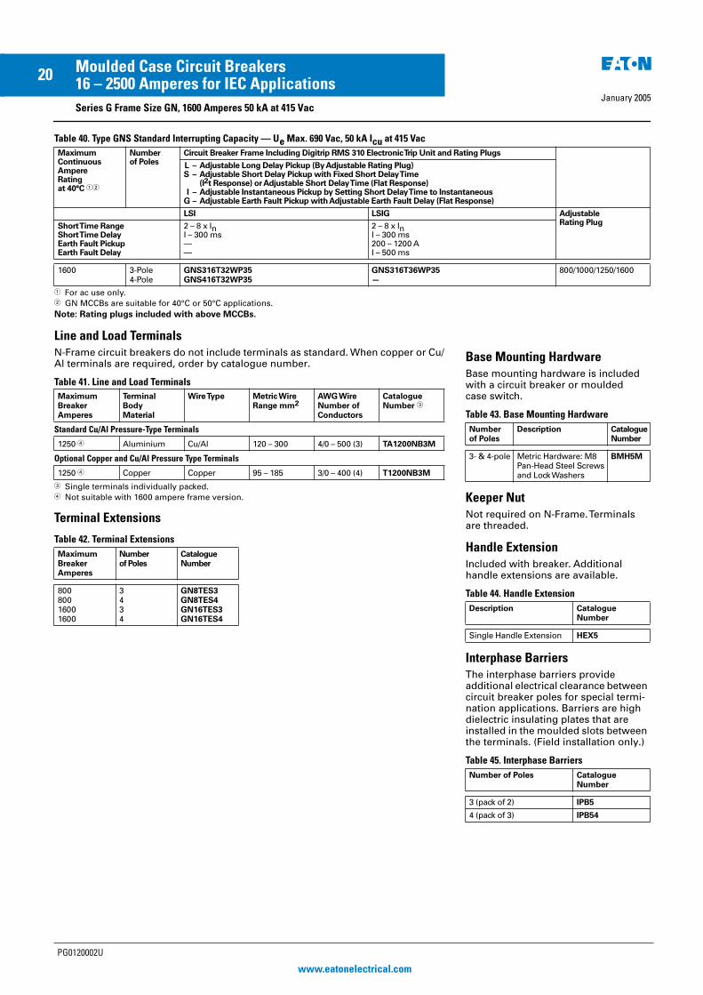
Table 40. Type GNS Standard Interrupting Capacity — Ue Max. 690 Vac, 50 kA Icu at 415 Vac
Line and Load Terminals
N-Frame circuit breakers do not include terminals as standard. When copper or Cu/Al terminals are required, order by catalogue number.
Table 41. Line and Load Terminals
� Single terminals individually packed.� Not suitable with 1600 ampere frame version.
Terminal Extensions
Table 42. Terminal Extensions
Maximum Continuous Ampere Rating at 40°C ��
Number of Poles
Circuit Breaker Frame Including Digitrip RMS 310 Electronic Trip Unit and Rating Plugs
L – Adjustable Long Delay Pickup (By Adjustable Rating Plug)S – Adjustable Short Delay Pickup with Fixed Short Delay Time
(I2t Response) or Adjustable Short Delay Time (Flat Response)I – Adjustable Instantaneous Pickup by Setting Short Delay Time to Instantaneous
G – Adjustable Earth Fault Pickup with Adjustable Earth Fault Delay (Flat Response)
LSI LSIG AdjustableRating PlugShort Time Range
Short Time DelayEarth Fault PickupEarth Fault Delay
2 – 8 x InI – 300 ms——
2 – 8 x InI – 300 ms200 – 1200 AI – 500 ms
1600 3-Pole4-Pole
GNS316T32WP35GNS416T32WP35
GNS316T36WP35—
800/1000/1250/1600
� For ac use only.� GN MCCBs are suitable for 40°C or 50°C applications.
Note: Rating plugs included with above MCCBs.
MaximumBreakerAmperes
TerminalBodyMaterial
Wire Type Metric WireRange mm2
AWG WireNumber ofConductors
CatalogueNumber �
Standard Cu/Al Pressure-Type Terminals
1250 � Aluminium Cu/Al 120 – 300 4/0 – 500 (3) TA1200NB3M
Optional Copper and Cu/Al Pressure Type Terminals
1250 � Copper Copper 95 – 185 3/0 – 400 (4) T1200NB3M
MaximumBreaker Amperes
Number of Poles
Catalogue Number
80080016001600
3434
GN8TES3GN8TES4GN16TES3GN16TES4
Base Mounting Hardware
Base mounting hardware is included with a circuit breaker or moulded case switch.
Table 43. Base Mounting Hardware
Keeper Nut
Not required on N-Frame. Terminals are threaded.
Handle Extension
Included with breaker. Additional handle extensions are available.
Table 44. Handle Extension
Interphase Barriers
The interphase barriers provide additional electrical clearance between circuit breaker poles for special termi-nation applications. Barriers are high dielectric insulating plates that are installed in the moulded slots between the terminals. (Field installation only.)
Table 45. Interphase Barriers
Numberof Poles
Description CatalogueNumber
3- & 4-pole Metric Hardware: M8Pan-Head Steel Screwsand LockWashers
BMH5M
Description Catalogue Number
Single Handle Extension HEX5
Number of Poles Catalogue Number
3 (pack of 2) IPB5
4 (pack of 3) IPB54
PG0120002U
www.eatonelectrical.com
EE MCCB Series G PG Reprint 20/1/05 4:21 pm Page 20

21Moulded Case Circuit Breakers
January 200516 – 2500 Amperes for IEC Applications
Series G Frame Size GR, 2500 Amperes, 70 kA at 415 Vac — Digitrip 310 Trip Unit
GR-Frame, 2500 Amperes — Selection Guide and Ordering Information
Table 46. Type GRH with Digitrip 310 High Interrupting Capacity — Ue Max. 690 Vac, 70 kA Icu at 415 Vac
� For SCR application, use 2000 ampere frame.� Order terminals separately. Mounting hardware not included. See page 24.� Neutral pole on right side.Note: Rating plugs included with above MCCBs.
Maximum Continuous Ampere Rating at 40°C �
Number of Poles
Circuit Breaker Frame Including Digitrip RMS 310 Electronic Trip Unit withAdjustable Rating Plugs — Catalogue Number �
InterchangeableRating Plugs(Order as IndividualComponent)
Includedwith Breaker as standardL – Adjustable Long Delay Pickup (By Adjustable Rating Plug)
S – Adjustable Short Delay Pickup with Fixed Short Delay Time(I2t Response) or Adjustable Short Delay Time (Flat Response)
I – Adjustable Instantaneous Pickup by Setting Short Delay Time to InstantaneousG – Adjustable Earth Fault Pickup with Adjustable Earth Fault Delay (Flat Response)
LSI LSIG FixedRating Plug
AdjustableRating Plug
Short Time RangeShort Time DelayEarth Fault PickupEarth Fault Delay
2 – 8 x InI – 300 ms——
2 – 8 x InI – 300 ms200 – 1200 AI – 500 ms
Ampere Rating
CatalogueNumber
AdjustableAmpereSettingsCatalogue Number
1600 � 3-Pole GRH316T32WP08 GRH316T36WP08 800100012001250
16RES08T16RES10T16RES12T16RES125T
800/1000/1250/1600A16RES16T1
140015001600
16RES14T16RES15T16RES16T
2000 GRH320T32WP16 GRH320T36WP16 100012001250
20RES10TA20RES12T20RES125T
1000/1250/1600/2000A20RES20T1
140016002000
20RES14T20RES16T20RES20T
2500 GRH325T32WP39 GRH325T36WP39 120012501600
25RES12T25RES125T25RES16T
1250/1600/2000/2500A25RES25T1
20002500
25RES20T25RES25T
1600 � 4-Pole� GRH416T32WP08 — 800100012001250
16RES08T16RES10T16RES12T16RES125T
800/1000/1250/1600A16RES16T1
140015001600
16RES14T16RES15T16RES16T
2000 GRH420T32WP16 — 100012001250
20RES10TA20RES12T20RES125T
1000/1250/1600/2000A20RES20T1
140016002000
20RES14T20RES16T20RES20T
2500 GRH425T32WP39 — 125012001600
25RES125T25RES12T25RES16T
1250/1600/2000/2500A25RES25T1
20002500
25RES20T25RES25T
PG0120002U
www.eatonelectrical.com
EE MCCB Series G PG Reprint 20/1/05 4:21 pm Page 21
January 2005
22Moulded Case Circuit Breakers16 – 2500 Amperes for IEC Applications
Series G Frame Size GR, 2500 Amperes 100 kA at 415 Vac — Digitrip 310 Trip Unit
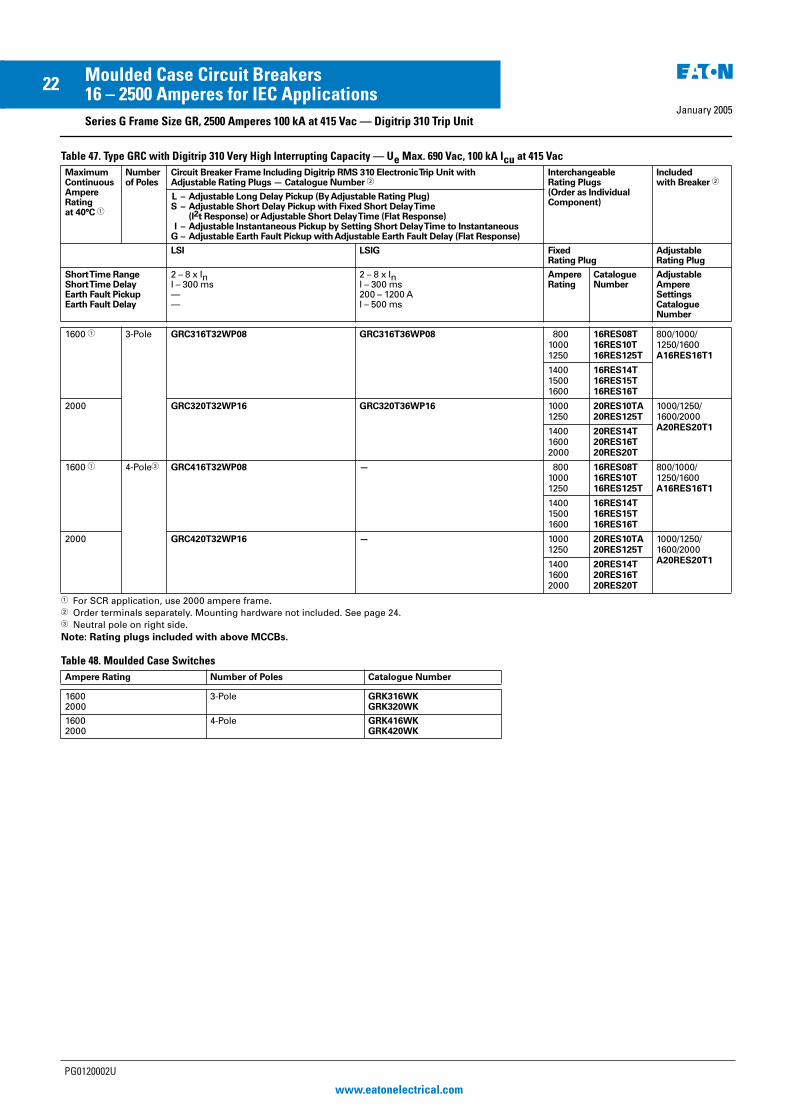
Table 47. Type GRC with Digitrip 310 Very High Interrupting Capacity — Ue Max. 690 Vac, 100 kA Icu at 415 Vac
� For SCR application, use 2000 ampere frame.� Order terminals separately. Mounting hardware not included. See page 24.� Neutral pole on right side.Note: Rating plugs included with above MCCBs.
Table 48. Moulded Case Switches
Maximum Continuous Ampere Rating at 40°C �
Number of Poles
Circuit Breaker Frame Including Digitrip RMS 310 Electronic Trip Unit withAdjustable Rating Plugs — Catalogue Number �
InterchangeableRating Plugs(Order as IndividualComponent)
Includedwith Breaker �
L – Adjustable Long Delay Pickup (By Adjustable Rating Plug)S – Adjustable Short Delay Pickup with Fixed Short Delay Time
(I2t Response) or Adjustable Short Delay Time (Flat Response)I – Adjustable Instantaneous Pickup by Setting Short Delay Time to Instantaneous
G – Adjustable Earth Fault Pickup with Adjustable Earth Fault Delay (Flat Response)
LSI LSIG FixedRating Plug
AdjustableRating Plug
Short Time RangeShort Time DelayEarth Fault PickupEarth Fault Delay
2 – 8 x InI – 300 ms——
2 – 8 x InI – 300 ms200 – 1200 AI – 500 ms
Ampere Rating
CatalogueNumber
AdjustableAmpereSettingsCatalogue Number
1600 � 3-Pole GRC316T32WP08 GRC316T36WP08 80010001250
16RES08T16RES10T16RES125T
800/1000/1250/1600A16RES16T1
140015001600
16RES14T16RES15T16RES16T
2000 GRC320T32WP16 GRC320T36WP16 10001250
20RES10TA20RES125T
1000/1250/1600/2000A20RES20T11400
16002000
20RES14T20RES16T20RES20T
1600 � 4-Pole� GRC416T32WP08 — 80010001250
16RES08T16RES10T16RES125T
800/1000/1250/1600A16RES16T1
140015001600
16RES14T16RES15T16RES16T
2000 GRC420T32WP16 — 10001250
20RES10TA20RES125T
1000/1250/1600/2000A20RES20T11400
16002000
20RES14T20RES16T20RES20T
Ampere Rating Number of Poles Catalogue Number
16002000
3-Pole GRK316WKGRK320WK
16002000
4-Pole GRK416WKGRK420WK
PG0120002U
www.eatonelectrical.com
EE MCCB Series G PG Reprint 20/1/05 4:21 pm Page 22

January 2005
23Moulded Case Circuit Breakers16 – 2500 Amperes for IEC Applications
Series G Frame Size GR, 1250 Amperes — Digitrip 610 & 910 Trip Units
Table 49. Type GR with Digitrip 610 and 910
� Order terminals separately. Mounting hardware not included. See page 24.Note: Rating plugs included with above MCCBs.
Maximum Continuous Ampere Rating at 40°C
Numberof Poles
Circuit Breaker Frame Including Digitrip RMS 610 and 910 Electronic Trip Unit with Rating PlugsOrder as Individual Component — Catalogue Number �
Digitrip RMS InterchangeableRating Plug (Order as IndividualComponent)
L – Adjustable Long Delay Pickup (Ir) with Adjustable Long Delay TimeS – Adjustable Short Delay Pickup with Adjustable Short Delay Time (I2t or Flat Response)I – Adjustable Instantaneous Pickup
G – Adjustable Earth Fault Pickup with Adjustable Earth Fault Time Delay (I2t or Flat Response)
LSI LSIG Fixed Rating Plug
Long Delay PickupLong Delay Time Short Time RangeShort Time DelayInstantaneous Earth Fault PickupEarth Fault Delay
0.5 – 1.0 x In2 – 24 Seconds2 – 6 x Ir100 – 500 ms2 – 6 x M1 & M2——
0.5 – 1.0 x In2 – 24 Seconds2 – 6 x Ir100 – 500 ms2 – 6 x M1 & M20.25 – 1.0 x In �100 – 500 ms
AmpereRating
CatalogueNumber
Type GRH with Digitrip 610 High Interrupting Capacity — Ue Max. 690 Vac, 70 kA Icu at 415 Vac
1600 3-Pole GRH316T62WP44 GRH316T66WP44 800100012501600
RP6R16A080RP6R16A100RP6R16A125RP6R16A160
2000 GRH320T62WP49 GRH320T66WP49 1000125016002000
RP6R20A100RP6R20A125RP6R20A160RP6R20A200
2500 GRH325T62WP53 GRH325T66WP53 160020002500
RP6R25A160RP6R25A200RP6R25A250
Type GRC with Digitrip 610 Very High Interrupting Capacity — Ue Max. 690 Vac, 100 kA Icu at 415 Vac
1600 3-Pole GRC316T62WP44 GRC316T66WP44 800100012501600
RP6R16A080RP6R16A100RP6R16A125RP6R16A160
2000 GRC320T62WP49 GRC320T66WP49 1000125016002000
RP6R20A100RP6R20A125RP6R20A160RP6R20A200
Type GRH with Digitrip 910 High Interrupting Capacity — Ue Max. 690 Vac, 70 kA Icu at 415 Vac
1600 3-Pole GRH316T92WP44 GRH316T96WP44 800100012501600
RP6R16A080RP6R16A100RP6R16A125RP6R16A160
2000 GRH320T92WP49 GRH320T96WP49 1000125016002000
RP6R20A100RP6R20A125RP6R20A160RP6R20A200
2500 GRH325T92WP53 GRH325T96WP53 160020002500
RP6R25A160RP6R25A200RP6R25A250
Type GRC with Digitrip 910 Very High Interrupting Capacity — Ue Max. 690 Vac, 100 kA Icu at 415 Vac
1600 3-Pole GRC316T92WP44 GRC316T96WP44 800100012501600
RP6R16A080RP6R16A100RP6R16A125RP6R16A160
2000 GRC320T92WP49 GRC320T96WP49 1000125016002000
RP6R20A100RP6R20A125RP6R20A160RP6R20A200
PG0120002U
www.eatonelectrical.com
EE MCCB Series G PG Reprint 20/1/05 4:21 pm Page 23
January 2005
24Moulded Case Circuit Breakers16 – 2500 Amperes for IEC Applications
Series G Frame Size GR, 800 – 2500 Amperes
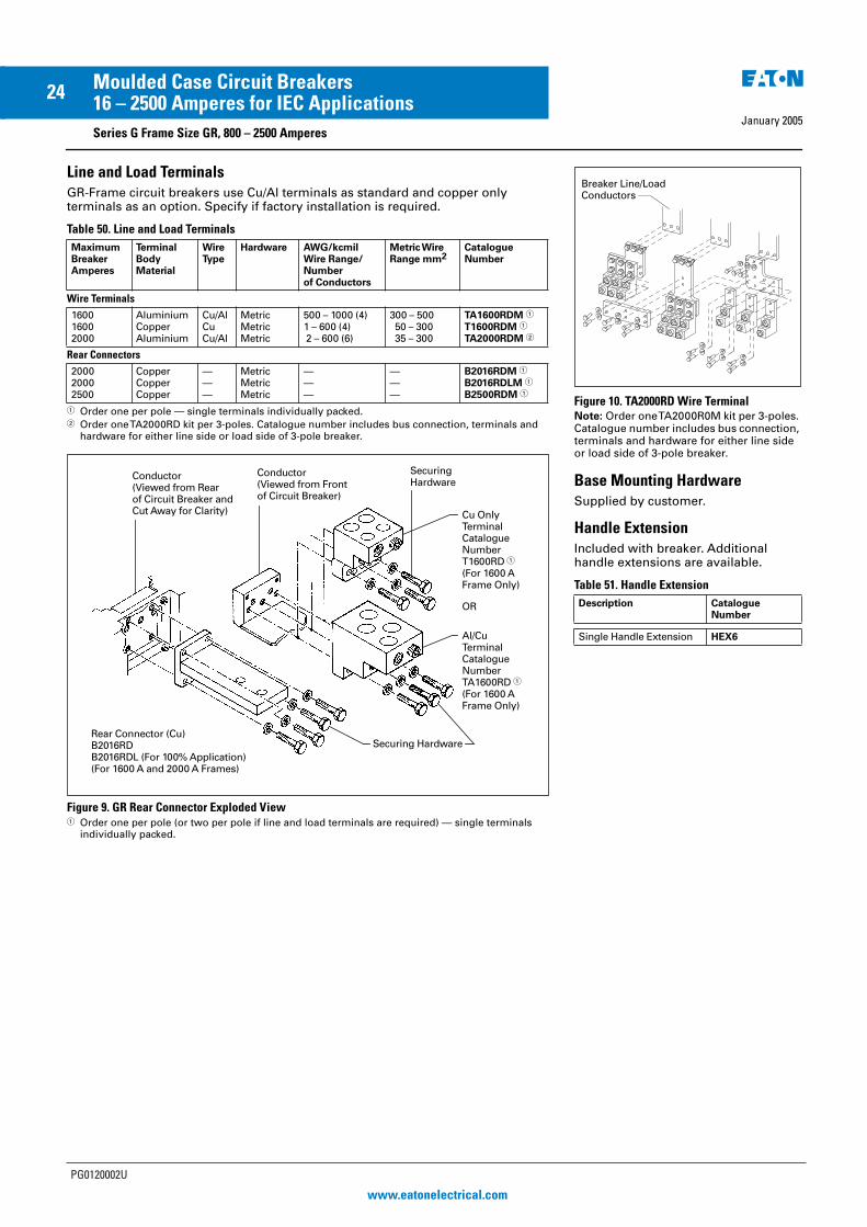
Line and Load Terminals
GR-Frame circuit breakers use Cu/Al terminals as standard and copper only terminals as an option. Specify if factory installation is required.
Table 50. Line and Load Terminals
� Order one per pole — single terminals individually packed.� Order one TA2000RD kit per 3-poles. Catalogue number includes bus connection, terminals and
hardware for either line side or load side of 3-pole breaker.
Figure 9. GR Rear Connector Exploded View� Order one per pole (or two per pole if line and load terminals are required) — single terminals
individually packed.
MaximumBreakerAmperes
TerminalBodyMaterial
WireType
Hardware AWG/kcmilWire Range/Numberof Conductors
Metric WireRange mm2
CatalogueNumber
Wire Terminals
160016002000
AluminiumCopperAluminium
Cu/AlCuCu/Al
MetricMetricMetric
500 – 1000 (4)1 – 600 (4) 2 – 600 (6)
300 – 500 50 – 300 35 – 300
TA1600RDM �
T1600RDM �
TA2000RDM �
Rear Connectors
200020002500
CopperCopperCopper
———
MetricMetricMetric
———
———
B2016RDM �
B2016RDLM �
B2500RDM �
Conductor(Viewed from Frontof Circuit Breaker)
Conductor(Viewed from Rearof Circuit Breaker and Cut Away for Clarity)
Rear Connector (Cu)B2016RDB2016RDL (For 100% Application)(For 1600 A and 2000 A Frames)
SecuringHardware
Securing Hardware
Cu OnlyTerminalCatalogue NumberT1600RD �
(For 1600 AFrame Only)
Al/CuTerminalCatalogue NumberTA1600RD �
(For 1600 AFrame Only)
OR
Figure 10. TA2000RD Wire Terminal
Note: Order one TA2000R0M kit per 3-poles. Catalogue number includes bus connection, terminals and hardware for either line side or load side of 3-pole breaker.
Base Mounting Hardware
Supplied by customer.
Handle Extension
Included with breaker. Additional handle extensions are available.
Table 51. Handle Extension
Description Catalogue Number
Single Handle Extension HEX6
NEED ARTFROM PG. 29 OF PG.29B.01A.T.U
(FEB, 2001)
Breaker Line/LoadConductors
PG0120002U
www.eatonelectrical.com
EE MCCB Series G PG Reprint 20/1/05 4:21 pm Page 24

January 2005
25Moulded Case Circuit Breakers16 – 2500 Amperes for IEC Applications
Series G Motor Circuit Protectors
Motor Circuit Protectors — Selection Guide and Ordering Information
Table 52. GE Frame — 600Y/347 Vac Maximum, 250 Vdc Maximum
� Motor FLA ranges are typical. The corresponding trip setting is at 13 times the minimum FLA value shown. Where a 13 times setting is required for an intermediate FLA value, alternate cam settings and/or MCP ratings should be used.
� For dc applications, actual trip levels are approximately 40% higher than values shown.
� Settings above 10xIn are for special applications. Where the ampere rating of the disconnecting means cannot be less than 115% of the motor full load ampere rating.
Table 53. GJ Frame — 600 Vac Maximum, 250 Vdc Maximum
Table 54. GL Frame — 600 Vac Maximum, 250 Vdc Maximum �
� Equipped with an electronic trip device.
Table 55. GN Frame — 600 Vac Maximum �
� Equipped with an electronic trip device.
ContinuousAmperes
CamSetting
Motor Full Load Current Amperes �
MCP Trip Setting �
MCP CatalogueNumber
3 ABCDEF
.69 –.911.1 – 1.31.6 – 1.72.0 – 2.22.3 – 2.5 – 2.6
9 15 21 27 30 33
HMCPE003A0C
7 ABCDEF
1.5 – 2.0 2.6 – 3.1 3.7 – 3.9 4.8 – 5.2 5.3 – 5.7 5.8 – 6.1
21 35 49 63 70 77
HMCPE007C0C
15 ABCDEF
3.4 – 4.5 5.7 – 6.8 8.0 – 9.110.4 – 11.411.5 – 12.612.7 – 13.0
45 75 105 135 150 165
HMCPE015E0C
30 ABCDEF
3.9 – 9.111.5 – 13.716.1 – 18.320.7 – 22.923.0 – 25.225.3 – 26.1
90 150 210 270 300 330
HMCPE030H1C
50 ABCDEF
11.5 – 15.219.2 – 22.926.9 – 30.634.6 – 38.338.4 – 42.142.2 – 43.5
150 250 350 450 500 550
HMCPE050K2C
70 ABCDEF
16.1 – 30.626.9 – 32.237.6 – 42.948.4 – 53.753.8 – 59.159.2 – 60.9
210 350 490 630 700 770
HMCPE070M2C
100 ABCDEF
23.0 – 30.638.4 – 46.053.8 – 61.469.2 – 76.876.9 – 84.584.6 – 87.0
300 500 700 90010001100
HMCPE100R3C
100 ABCDEF
38.4 – 46.057.6 – 65.276.9 – 84.5�
�
�
500 7501000125013751500
HMCPE100T3C
ContinuousAmperes
MCP TripRange (Amperes)
MCP CatalogueNumber
250 500 – 1000 625 – 1250 750 – 1500
HMCPJ250D5LHMCPJ250F5LHMCPJ250G5L
875 – 17501000 – 20001125 – 22501250 – 2500
HMCPJ250J5LHMCPJ250K5LHMCPJ250L5LHMCPJ250W5L
ContinuousAmperes
MCP TripRange (Amperes)
MCP CatalogueNumber
600 1125 – 22501500 – 30001750 – 3500
HMCPL600LHMCPL600NHMCPL600R
2000 – 40002250 – 45002500 – 50003000 – 6000
HMCPL600XHMCPL600YHMCPL600PHMCPL600M
ContinuousAmperes
CamSetting
Motor Full LoadCurrent Amperes
MCP TripSetting
MCP CatalogueNumber
800 ABCDEFG
123.1 – 184.5184.6 – 246.1246.2 – 307.6307.2 – 369.1369.2 – 430.7430.8 – 492.2492.3 – 553.7
1600240032004000480056006400
HMCP800X7W
1200 ABCDEFG
184.6 –276.8276.9 – 369.1369.2 – 461.4461.5 – 553.7553.8 – 646.1646.2 – 738.4738.5 – 830.7
2400360048006000720084009600
HMCP12Y8W
PG0120002U
www.eatonelectrical.com
EE MCCB Series G PG Reprint 20/1/05 4:21 pm Page 25

January 2005
26Moulded Case Circuit Breakers16 – 2500 Amperes for IEC Applications
Series G Earth Leakage Modules
Earth Leakage Modules
Clockwise from Left: GJ, GL, GE MCCBs Shown with Earth Fault (Earth Leakage) Modules
Eaton offers a 3- and 4-pole 30 mA earth fault (earth leakage) protection module for GE, GJ and GL breakers. The module does not restrict the use of other breaker accessories. The IEC-rated GE module is side mounted for circuits up to 125 amperes, while the GJ and GL modules are both bottom mounted for circuits up to 160 and 250 amperes (GJ), or 400 and 630 amperes for the GL.
The module is completely self-containedsince the current sensor, relay and power supply are located inside the product. Current pickup settings are selectable from 0.03 – 10 amperes for all IEC-rated modules. Time delays are also selectable from Instantaneous – 1.0 seconds for 0.10 ampere settings and above. A current pickup setting of 0.03 amperes defaults to an Instan-taneous time setting regardless of the time dial’s position. Two alarm con-tacts come as standard: a 50% pretrip and a 100% after trip, both based only on earth leakage current levels.
Figure 11. IEC-Rated GL Frame Earth Leakage Module Faceplate
Product Selection
Table 56. GE Frame Earth Leakage Modules, IEC (Side Mounted, 230 – 415 Vac, 50/60 Hz)
Table 57. GJ Frame Earth Leakage Modules, IEC (Bottom Mounted, 230 – 415 Vac, 50/60 Hz)
Table 58. GL Frame Earth Leakage Modules,IEC (Bottom Mounted, 230 – 415 Vac, 50/60 Hz)
Amperes Poles CatalogueNumber
125125
34
ELESE3125WELESE4125W
Amperes Poles CatalogueNumber
160160
34
ELJBE3160WELJBE4160W
250250
34
ELJBE3250WELJBE4250W
Amperes Poles CatalogueNumber
400400
34
ELLBE3400WELLBE4400W
630630
34
ELLBE3630WELLBE4630W
PG0120002U
www.eatonelectrical.com
EE MCCB Series G PG Reprint 20/1/05 4:21 pm Page 26
January 2005
27Moulded Case Circuit Breakers16 – 2500 Amperes for IEC Applications
Series G Optional Features and Accessories
Optional Features andAccessories
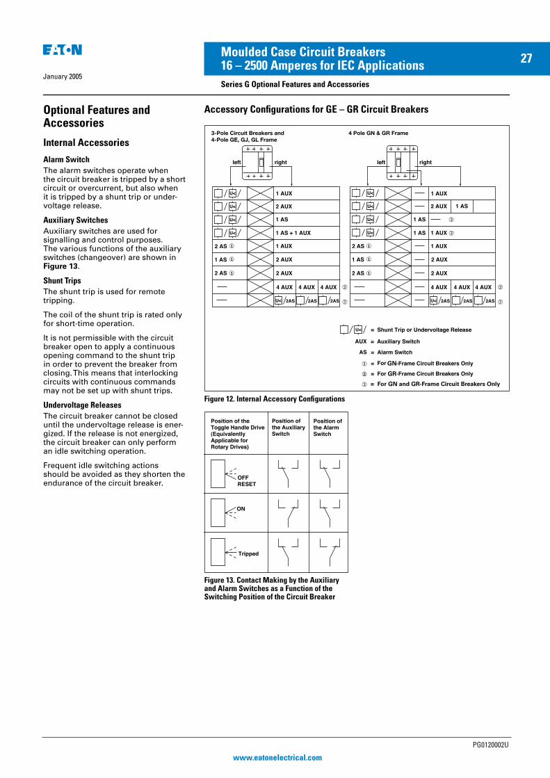
Internal Accessories
Alarm Switch
The alarm switches operate when the circuit breaker is tripped by a short circuit or overcurrent, but also when it is tripped by a shunt trip or under-voltage release.
Auxiliary Switches
Auxiliary switches are used for signalling and control purposes. The various functions of the auxiliary switches (changeover) are shown in Figure 13.
Shunt Trips
The shunt trip is used for remote tripping.
The coil of the shunt trip is rated only for short-time operation.
It is not permissible with the circuit breaker open to apply a continuous opening command to the shunt trip in order to prevent the breaker from closing. This means that interlocking circuits with continuous commands may not be set up with shunt trips.
Undervoltage Releases
The circuit breaker cannot be closed until the undervoltage release is ener-gized. If the release is not energized, the circuit breaker can only perform an idle switching operation.
Frequent idle switching actions should be avoided as they shorten the endurance of the circuit breaker.
Accessory Configurations for GE – GR Circuit Breakers
Figure 12. Internal Accessory Configurations
Figure 13. Contact Making by the Auxiliary and Alarm Switches as a Function of the Switching Position of the Circuit Breaker
GR
GN�
�
�
�
�
�
�
�
�
�
�
�
� = For GN and GR-Frame Circuit Breakers Only
�
�
3-Pole Circuit Breakers and 4-Pole GE, GJ, GL Frame
4 Pole GN & GR Frame
PG0120002U
www.eatonelectrical.com
EE MCCB Series G PG Reprint 20/1/05 4:21 pm Page 27

January 2005
28Moulded Case Circuit Breakers16 – 2500 Amperes for IEC Applications
Series G Accessories
Table 59. Accessories
Description PoleLocation
Frame
GE, GJ, GL GN GR
Field Fit Kit Catalogue Numbers
Alarm Switch Make/Break Left — — — —
Right ALM1M1BEPK ALM1M1BJPKL A1L5RPK A1L6RPK
2 Make/2 Break Left — — — —
Right ALM2M2BEPK ALM2M2BJPK A2L5RPK A2L6RPK
Auxiliary Switch 1A, 1B Left — — — —
Right AUX1A1BPK AUX1A1BPK A1X5PK —
2A, 2B Left — — — —
Right AUX2A2BPK AUX2A2BPK A2X5PK A2X6RPK
3A, 3B Left — — — —
Right — — A3X5RPK —
4A, 4B Left — — — —
Right — — — A4X6RPK
Auxiliary Switch /Alarm Switch Left — — AA115LPK —
Right AUXALRMEPK AUXALRMJPK AA115RPK —
Shunt Trip — Standard 120 Vac Left SNT120CPK SNT120CPK SNT5LP11K —
Right — — — SNT6P11K
240 Vac Left SNT120CPK SNT120CPK SNT5LP11K —
Right — — — SNT6P11K
24 Vdc Left SNT060CPK SNT060CPK SNT5LP03K —
Right — — — SNT6P03K
48 Vdc Left SNT060CPK SNT060CPK SNT5LP23K —
Right — — — SNT6P23K
380 – 600 Vac Left SNT480CPK SNT480CPK — —
Right — — — —
220 – 250 Vdc or 380 – 440 Vac — — SNT5LP14K SNT6P14K
480 – 600 Vac — — SNT5LP18K SNT6P18K
Shunt Trip — Low Energy Left — — LST5LPK —
Right — — — LST6RPK
Undervoltage Release Mechanism 120 Vac Left UVR120APK UVR120APK UVH5LP08K —
Right — — — UVH6RP08K
208 – 240 Vac Left UVR240APK UVR240APK UVH5LP11K —
Right — — — UVH6RP11K
24 Vdc, Vac Left UVR024CPK UVR024CPK UVH5LP21K —
Right — — — UVH6RP21K
48 Vdc Left UVR048DPK UVR048DPK UVH5LP23K —
Right — — — UVH6RP23K
12 Vdc, Vac Left UVR012CPK UVR012CPK — —
Right — — — —
48 Vac Left UVR048APK UVR048APK UVH5LP05K —
Right — — — UVH6RP05K
120 Vdc Left UVR125DPK UVR125DPK UVH5LP26K —
Right — — — UVH6RP26K
220 – 250 Vdc Left UVR250DPK UVR250DPK UVH5LP28K —
Right — — — UVH6RP28K
380 – 500 Vac Left UVR480APK UVR480APK UVH5LP29K —
Right — — — UVH6RP29K
525 – 600 Vac Left UVR600APK UVR600APK — —
Right — — — —
12 Vdc Left — — UVH5LP20K —
Right — — — UVH6RP20K
12 Vac Left — — UVH5LP02K —
Right — — — UVH6RP02K
Make
Break
a
b
ST
c
UV
PG0120002U
www.eatonelectrical.com
EE MCCB Series G PG Reprint 20/1/05 4:21 pm Page 28
January 2005
29Moulded Case Circuit Breakers16 – 2500 Amperes for IEC ApplicationsSeries G Optional Features and Accessories
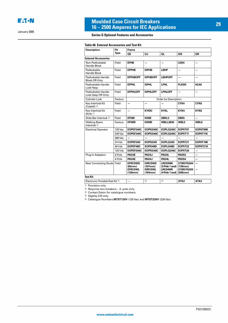
Table 60. External Accessories and Test Kit
� Provision only.� Requires two breakers – 3- pole only.� Contact Eaton for catalogue numbers.� Digitrip 310 only.� Catalogue Numbers MTST120V (120 Vac) and MTST230V (230 Vac).
Description FitType
Frame
GE GJ GL GN GR
External AccessoriesNon-PadlockableHandle Block
Field EFHB — — LKD4 —
PadlockableHandle Block
Field EFPHB FJPHB LBHP — —
Padlockable Handle Block Off-Only
Field EFPHBOFF FJPHBOFF LBHPOFF — —
Padlockable HandleLock Hasp
Field EFPHL FJPHL LPHL PLK5N HLK6
Padlockable HandleLock Hasp Off-Only
Field EFPHLOFF FJPHLOFF LPHLOFF — —
Cylinder Lock Factory Order by Description
Key Interlock Kit (Castell) �
Field — — — CYK4 CYK6
Key Interlock Kit (Kirk) �
Field — KYKFJ KYKL KYK4 KYK6
Slide Bar Interlock � Field EFSBI FJSBI SBKL3 SBK5 —
Walking BeamInterlock �
Factory EFWBI FJWBI WBLL3630 WBL5 WBL6
Electrical Operator 120 Vac EOPEF240C EOPFJ240C EOPLG240C EOP5T07 EOP6T08K
240 Vac EOPEF240C EOPFJ240C EOPLG240C EOP5T11 EOP6T11K
380 Vac — — — — —
24 Vdc EOPEF24D EOPFJ24D EOPLG24D EOP5T21 EOP6T19K
48 Vdc EOPEF48D EOPFJ48D EOPLG48D EOP5T22 EOP6T21K
125 Vdc EOPEF240C EOPFJ240C EOPLG240C EOP5T26 —
Plug-In Adapters 3-Pole PAD3E PAD3J PAD3L PAD53 —
4-Pole PAD4E PAD4J PAD4L PAD54 —
Rear Connecting Studs Field EFRCSWS (83mm)EFRCSWL (128mm)
FJRCSWS (107mm)FJRCSWL (184mm)
LRCS3WK (3-Pole 1 end)LRCS4WK (4-Pole 1 end)
373B375G04 (139mm)373B375G03 (266mm)
—
—
Test KitElectronic Portable Test Kit � — � � STK2 STK2
PG0120002U
www.eatonelectrical.com
EE MCCB Series G PG Reprint 20/1/05 4:21 pm Page 29

January 2005
30Moulded Case Circuit Breakers16 – 2500 Amperes for IEC Applications
Series G Plug-in Blocks and Drawout Cassettes
Plug-in Blocks
Plug-in adapters simplify installation and front removal of circuit breakers. Plug-ins are available for rear connec-tion applications on 3- and 4-pole circuit breakers. Trip on drawout interlock kits are included. Use terminal shields for IP30 protection.
GL Breaker with Plug-in Block
Product Selection
Table 61. Plug-in Blocks
� Included with plug-in block. Trips the breaker when breaker is removed from plug-in block.
Drawout Cassette
Drawout Cassette
The Drawout Cassette is currently for use with the standard 3-pole 65 and 100 kA/480 Vac, 1600 ampere and 2000 ampere GR circuit breakers only. It consists of two separate components: the movable mechanism which is factory mounted to the circuit breaker frame (shown in photo above) and the stationary mechanism which is housed in the cassette and shipped separately.
The drawout mechanism has four positions.
� Connected — The breaker is fully connected to the primary stabs and secondary contacts.
� Test — The breaker is not connected to the primary stab but is connected to the secondary contacts.
� Disconnected — Both the primary stabs and the secondary contacts are disconnected.
� Withdraw — The breaker can be removed from the cassette.
BreakerFrame
Poles CatalogueNumber
GE-, GJ- and GL-Frame Plug-in Blocks
GEGE
34
PAD3EPAD4E
GJGJ
34
PAD3JPAD4J
GLGL
34
PAD3LPAD4L
Trip-on Drawout Interlock Kit �
GEGJGL
3, 43, 43, 4
PIILEGPIILJGPIILLG
Terminal Shields IP30
GEGE
34
EFTS3KEFTS4K
GJGJ
34
FJTS3KFJTS4K
GLGL
34
LTS3KLTS4K
Table 62. GR Drawout Cassette
� List price included in price of the stationary mechanism.
Movable mechanism must be ordered with GR circuit breaker and is shipped mounted to circuit breaker frame. Stationary mechanism is ordered separately.
All internal accessories must be factoryinstalled for use with drawout.
Description Catalogue Number
65 kA/480 Vac Version
MovableMechanism
RG20DOM �
StationaryMechanism
RG20DOS (without shutters)RG20DOSS (with shutters)
100 kA/480 Vac Version
MovableMechanism
RG20DOM �
StationaryMechanism
RG20DOS (without shutters)RG20DOSS (with shutters)
PG0120002U
www.eatonelectrical.com
EE MCCB Series G PG Reprint 20/1/05 4:21 pm Page 30
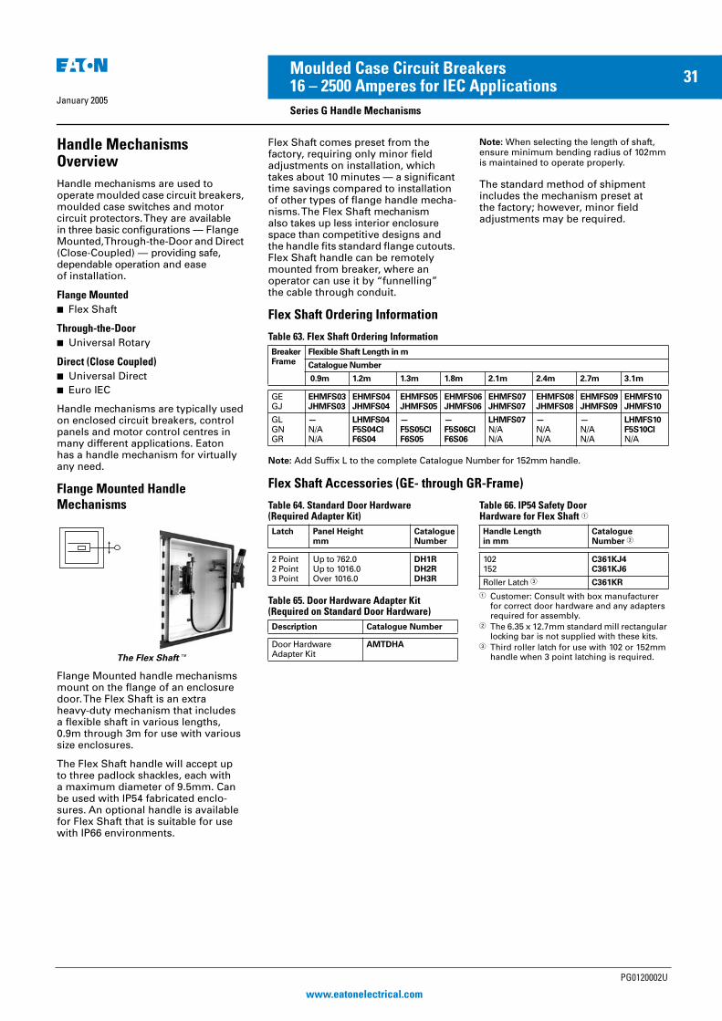
January 2005
31Moulded Case Circuit Breakers16 – 2500 Amperes for IEC Applications
Series G Handle Mechanisms
Handle MechanismsOverview
Handle mechanisms are used to operate moulded case circuit breakers, moulded case switches and motor circuit protectors. They are available in three basic configurations — Flange Mounted, Through-the-Door and Direct (Close-Coupled) — providing safe, dependable operation and ease of installation.
Flange Mounted
� Flex Shaft
Through-the-Door
� Universal Rotary
Direct (Close Coupled)
� Universal Direct
� Euro IEC
Handle mechanisms are typically used on enclosed circuit breakers, control panels and motor control centres in many different applications. Eaton has a handle mechanism for virtually any need.
Flange Mounted Handle
Mechanisms
The Flex Shaft�
Flange Mounted handle mechanisms mount on the flange of an enclosure door. The Flex Shaft is an extra heavy-duty mechanism that includesa flexible shaft in various lengths, 0.9m through 3m for use with various size enclosures.
The Flex Shaft handle will accept up to three padlock shackles, each with a maximum diameter of 9.5mm. Can be used with IP54 fabricated enclo-sures. An optional handle is available for Flex Shaft that is suitable for use with IP66 environments.
Flex Shaft comes preset from the factory, requiring only minor field adjustments on installation, which takes about 10 minutes — a significant time savings compared to installation of other types of flange handle mecha-nisms. The Flex Shaft mechanism also takes up less interior enclosure space than competitive designs and the handle fits standard flange cutouts. Flex Shaft handle can be remotely mounted from breaker, where an operator can use it by “funnelling” the cable through conduit.
Note: When selecting the length of shaft, ensure minimum bending radius of 102mm is maintained to operate properly.
The standard method of shipment includes the mechanism preset at the factory; however, minor field adjustments may be required.
Flex Shaft Ordering Information
Table 63. Flex Shaft Ordering Information
Note: Add Suffix L to the complete Catalogue Number for 152mm handle.
Flex Shaft Accessories (GE- through GR-Frame)
Table 64. Standard Door Hardware (Required Adapter Kit)
Table 65. Door Hardware Adapter Kit(Required on Standard Door Hardware)
Table 66. IP54 Safety Door Hardware for Flex Shaft �
� Customer: Consult with box manufacturer for correct door hardware and any adapters required for assembly.
� The 6.35 x 12.7mm standard mill rectangular locking bar is not supplied with these kits.
� Third roller latch for use with 102 or 152mm handle when 3 point latching is required.
BreakerFrame
Flexible Shaft Length in m
Catalogue Number
0.9m 1.2m 1.3m 1.8m 2.1m 2.4m 2.7m 3.1m
GEGJ
EHMFS03JHMFS03
EHMFS04JHMFS04
EHMFS05JHMFS05
EHMFS06JHMFS06
EHMFS07JHMFS07
EHMFS08JHMFS08
EHMFS09JHMFS09
EHMFS10JHMFS10
GLGNGR
—N/AN/A
LHMFS04F5S04CIF6S04
—F5S05CIF6S05
—F5S06CIF6S06
LHMFS07N/AN/A
—N/AN/A
—N/AN/A
LHMFS10F5S10CIN/A
Latch Panel Heightmm
CatalogueNumber
2 Point2 Point3 Point
Up to 762.0Up to 1016.0Over 1016.0
DH1RDH2RDH3R
Description Catalogue Number
Door HardwareAdapter Kit
AMTDHA
Handle Lengthin mm
CatalogueNumber �
102152
C361KJ4C361KJ6
Roller Latch � C361KR
PG0120002U
www.eatonelectrical.com
EE MCCB Series G PG Reprint 20/1/05 4:21 pm Page 31
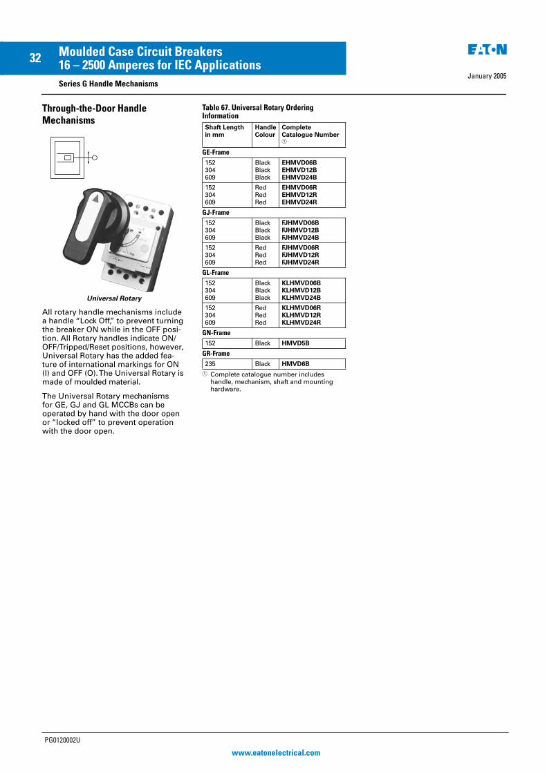
January 2005
32Moulded Case Circuit Breakers16 – 2500 Amperes for IEC Applications
Series G Handle Mechanisms
Through-the-Door Handle
Mechanisms
Universal Rotary
All rotary handle mechanisms include a handle “Lock Off,” to prevent turning the breaker ON while in the OFF posi-tion. All Rotary handles indicate ON/OFF/Tripped/Reset positions, however, Universal Rotary has the added fea-ture of international markings for ON (I) and OFF (O). The Universal Rotary is made of moulded material.
The Universal Rotary mechanisms for GE, GJ and GL MCCBs can be operated by hand with the door open or “locked off” to prevent operation with the door open.
Table 67. Universal Rotary Ordering Information
� Complete catalogue number includes handle, mechanism, shaft and mounting hardware.
Shaft Lengthin mm
HandleColour
CompleteCatalogue Number �
GE-Frame
152304609
BlackBlackBlack
EHMVD06BEHMVD12BEHMVD24B
152304609
RedRedRed
EHMVD06REHMVD12REHMVD24R
GJ-Frame
152304609
BlackBlackBlack
FJHMVD06BFJHMVD12BFJHMVD24B
152304609
RedRedRed
FJHMVD06RFJHMVD12RFJHMVD24R
GL-Frame
152304609
BlackBlackBlack
KLHMVD06BKLHMVD12BKLHMVD24B
152304609
RedRedRed
KLHMVD06RKLHMVD12RKLHMVD24R
GN-Frame
152 Black HMVD5B
GR-Frame
235 Black HMVD6B
PG0120002U
www.eatonelectrical.com
EE MCCB Series G PG Reprint 20/1/05 4:21 pm Page 32

January 2005
33Moulded Case Circuit Breakers16 – 2500 Amperes for IEC Applications
Series G Handle Mechanisms
Direct (Close-Coupled)
Handle Mechanisms
Universal Direct (GE – GL)
Direct (Close-Coupled) Handle Mechanisms mount directly to the circuit breaker. They are used in shal-low enclosures where the standard variable depth Through-the-Door type mechanism is not practical or cannot be used. They are typically for applica-tions where high volume, standardized enclosures are being fabricated.
The Direct handle mechanism is designed exclusively for the Eaton GE, GJ and GL circuit breakers. It is availa-ble as standard with a door interlock to
prevent opening the enclosure while the circuit breaker is in the ON position. It is also available without a door interlock.
Table 68. Universal Direct Ordering Information
Frame Red Handle Colour
with Interlock without Interlock without Interlock
Catalogue Number
GEGJGL
EHMCCBIJHMCCBILHMCCBI
EHMCCBJHMCCBLHMCCB
EHMCCRJHMCCRLHMCCR
PG0120002U
www.eatonelectrical.com
EE MCCB Series G PG Reprint 20/1/05 4:21 pm Page 33

January 2005
34Moulded Case Circuit Breakers16 – 2500 Amperes for IEC Applications
Series G
Time-Current Curves
Tripping Characteristics
The operating values specified forthe inverse time overcurrent releases (thermal overload releases, “a” releases) are mean values of the scatter bands of all setting ranges from the cold state and with uniform current loading of the conducting paths.
The tripping characteristics of the instantaneous (electromagnetic) short circuit releases (“n” releases) are based on the rated phase current Inwhich in the case of circuit breakers with adjustable thermal overload releases is also the upper value of the setting range. With a lower setting current, a correspondingly higher multiple is obtained for the operating current of the “n” release.
Figure 14. Tripping Time Characteristics (Thermal Memory)
0 1 5
Type GE
Tripping characteristics of GE circuit breakers for plant protection, “n” release fixed setting = 400 – 600 for breaker 15 – 45 A; over 50 A = 10x In.
Figure 15. GE Time Current Curve
Type GJ
Tripping characteristics of GJ circuit breakers for plant protection,“n” release adjustable.
Figure 16. GJ Time Current Curve for Thermal Magnetic Trip Units
Type GL
Figure 17. GL Time Current Curve for Thermal Magnetic Trip Units
100 2 4 6 8 101 2 4 6 8 102 2 4 6 8 103
10000
500030002000
1000
500300200
100
503020
10
532
1
.5
.3
.2
.1
.05
.03
.02
.01
.005
.003
.002
.001
TIM
E I
N S
EC
ON
DS
CURRENT IN MULTIPLES OF In
(a)
50-125
20
25
30-32 15-16
3540
45 (c) (d)
Max. Trip Time
Min. TripTime
100 2 4 6 8 101 2 4 6 8 102 2 4 6 8 103
10000
500030002000
1000
500300200
100
503020
10
532
1
.5
.3
.2
.1
.05
.03
.02
.01
.005
.003
.002
.001
TIM
E I
N S
EC
ON
DS
CURRENT IN MULTIPLES OF In
(b)
10XIn
(a)
5XIn
Max. Trip Time
Min.TripTime
(c)(d)
PG0120002U
www.eatonelectrical.com
EE MCCB Series G PG Reprint 20/1/05 4:21 pm Page 34

January 2005
35Moulded Case Circuit Breakers16 – 2500 Amperes for IEC Applications
Series G
Figure 18. GL Electronic Trip Unit Long Delay Response and Short Delay with I2T Response Curve
PG0120002U
www.eatonelectrical.com
EE MCCB Series G PG Reprint 20/1/05 4:21 pm Page 35
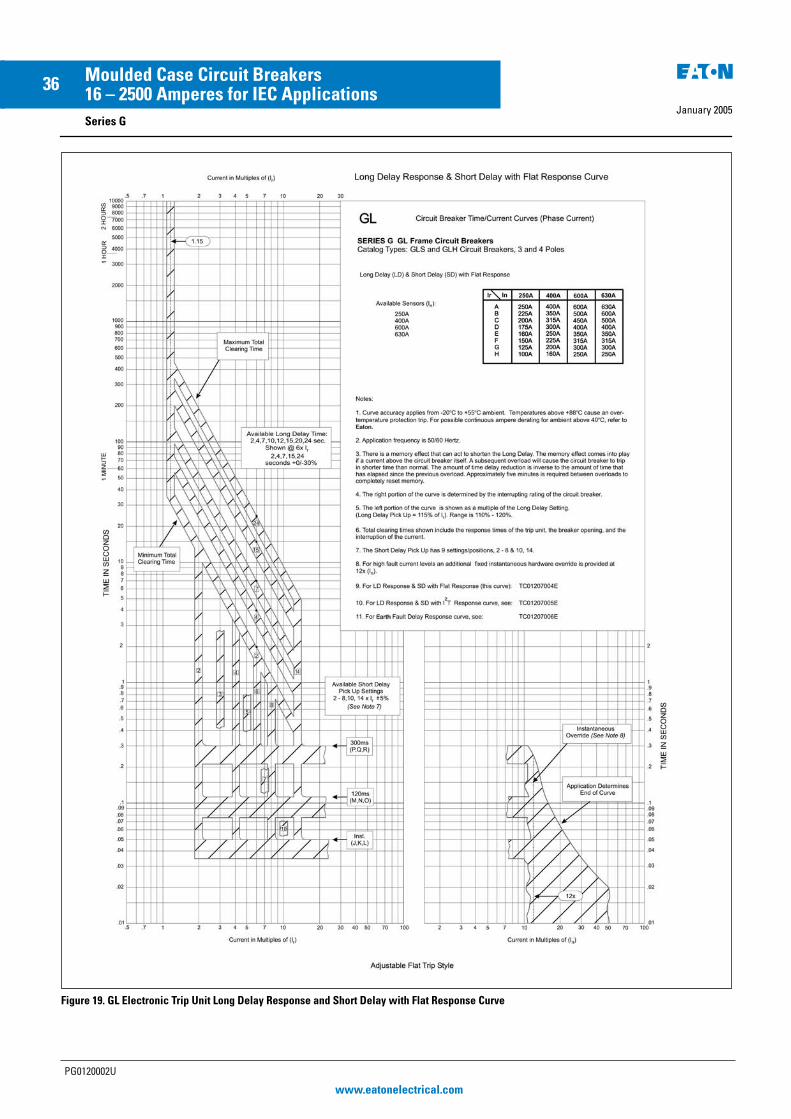
January 2005
36Moulded Case Circuit Breakers16 – 2500 Amperes for IEC Applications
Series G
Figure 19. GL Electronic Trip Unit Long Delay Response and Short Delay with Flat Response Curve
PG0120002U
www.eatonelectrical.com
EE MCCB Series G PG Reprint 20/1/05 4:21 pm Page 36

January 2005
37Moulded Case Circuit Breakers16 – 2500 Amperes for IEC Applications
Series G
Figure 20. GL Electronic Trip Unit Earth Fault Delay Response Curve
PG0120002U
www.eatonelectrical.com
EE MCCB Series G PG Reprint 20/1/05 4:21 pm Page 37

January 2005
38Moulded Case Circuit Breakers16 – 2500 Amperes for IEC Applications
Series G
Type GN
Tripping characteristics of GN circuit breakers with solid-state overcurrent release.
Working Temperature Range
The tolerance bands shown are appli-cable to an ambient temperature range of -5 to +60°C at the circuit breaker.
Figure 21. GN Time Current Curve for Digitrip 310 Trip Unit
1 2 3 4 5 6 8 10 15Xlr
7200
1000
500
200
100
50
20
10
5
2
1
.5
.2
.1
.05
.02
.01
.005
TIM
E I
N S
EC
ON
DS
CURRENT IN MULTIPLES OF In
1.5 10 15 20 30 40 60 80 100 200kA
Setting for ldas Multiples of lr(7x lr Not Shown)
2X
3X
4X
5X
6X
8X
7 X
Notes:
Inverse-time overload release “a”lr Set current (adjustable)
Short time delayed short circuit releaseld Tripping current (adjustable)td Delay time (adjustable)
Instantaneous short circuit release “n”li Tripping current (fixed setting)
td
300 ms
200 ms
100 ms
n
s
a
PG0120002U
www.eatonelectrical.com
EE MCCB Series G PG Reprint 20/1/05 4:21 pm Page 38

January 2005
39Moulded Case Circuit Breakers16 – 2500 Amperes for IEC Applications
Series G
Type GR
Tripping characteristics of GR circuit breakers with solid-state overcurrent release.
Working Temperature Range
The tolerance bands shown are appli-cable to an ambient temperature range of -5 to +60°C at the circuit breaker.
Figure 22. GR Time Current Curve for Digitrip 310 Trip Unit
1 2 3 4 5 6 8 10 15Xlr
7200
1000
500
200
100
50
20
10
5
2
1
.5
.2
.1
.05
.02
.01
.005
TIM
E I
N S
EC
ON
DS
CURRENT IN MULTIPLES OF In
1.5 10 15 20 30 40 60 80 100 200kA
Setting for ldas Multiples of lr(7X lr Not Shown)
2X
3X
4X
5X
6X
8X
7 X
td
300 ms
200 ms
100 ms
n
s
a
Notes:
Inverse-time overload release “a”lr Set current (adjustable)
Short time delayed short circuit releaseld Tripping current (adjustable)td Delay time (adjustable)
Instantaneous short circuit release “n”li Tripping current (fixed setting)
PG0120002U
www.eatonelectrical.com
EE MCCB Series G PG Reprint 20/1/05 4:21 pm Page 39
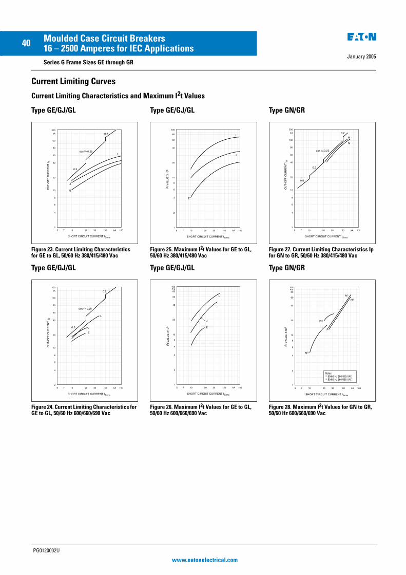
January 2005
40Moulded Case Circuit Breakers16 – 2500 Amperes for IEC Applications
Series G Frame Sizes GE through GR
Current Limiting Curves
Current Limiting Characteristics and Maximum I2t Values
Type GE/GJ/GL
Figure 23. Current Limiting Characteristics for GE to GL, 50/60 Hz 380/415/480 Vac
Type GE/GJ/GL
Figure 24. Current Limiting Characteristics for GE to GL, 50/60 Hz 600/660/690 Vac
Type GE/GJ/GL
Figure 25. Maximum I2t Values for GE to GL, 50/60 Hz 380/415/480 Vac
Type GE/GJ/GL
Figure 26. Maximum I2t Values for GE to GL, 50/60 Hz 600/660/690 Vac
Type GN/GR
Figure 27. Current Limiting Characteristics Ip for GN to GR, 50/60 Hz 380/415/480 Vac
Type GN/GR
Figure 28. Maximum I2t Values for GN to GR, 50/60 Hz 600/660/690 Vac
0.3
5 7 10 20 30 50 kA 100
200
kA
100
80
60
40
20
10
8
6
4
2
CU
T-O
FF
CU
RR
EN
T I
D
SHORT CIRCUIT CURRENT ISrms
0.2
E
J
Lcos =0.25
5 7 10 20 30 50 kA 100
200
kA
100
80
60
40
20
10
8
6
4
2
CU
T-O
FF
CU
RR
EN
T I
D
SHORT CIRCUIT CURRENT ISrms
0.3
0.2
E
J
L
cos =0.25
5 7 10 20 30 50 kA 100
100
80
60
40
20
10
6
4
2
1
I2tV
AL
UE
X1
05
SHORT CIRCUIT CURRENT ISrms
L
8
J
E
5 7 10 20 30 50 kA 100
100
80
60
40
20
10
6
4
2
1
I2tV
AL
UE
X1
05
SHORT CIRCUIT CURRENT ISrms
L
8
A2s
J
E
5 7 10 20 30 50 kA 100
200
kA
100
80
60
40
20
10
8
6
4
2
CU
T-O
FF
CU
RR
EN
T I
D
SHORT CIRCUIT CURRENT ISrms
0.3
0.2
R
N
0.5
cos =0.25
5 7 10 20 30 50 kA 100
100
80
60
40
20
10
6
4
2
1
I2 t
VA
LUE
X10
6
SHORT CIRCUIT CURRENT ISrms
8
A2s
N�
R�
R�
N�
Notes:� 50/60 Hz 380/415 VAC� 50/60 Hz 660/690 VAC
PG0120002U
www.eatonelectrical.com
EE MCCB Series G PG Reprint 20/1/05 4:21 pm Page 40

January 2005
41Moulded Case Circuit Breakers16 – 2500 Amperes for IEC ApplicationsSeries G Frame Sizes GE through GL
Dimensions
Figure 29. GE Frame — Dimensions in mm
Figure 30. GJ Frame — Dimensions in mm
Figure 31. GL-Frame — Dimensions in mmNote: TA63IL, T63IL, T632L, TA632L terminals add 30.2mm to line or load side of GL. LTS3K or LTS4K terminal covers add 54.1 mm to line or load side of GL.
Front ViewFront Cover Cutout
45.0CL
1P 25.42P 50.83P 76.24P 101.6 (Neutral pole on left)
Handle33.7
1P 26.02P 52.03P 77.04P 103.0
46.0
Side View
81.1
139.7
Front ViewFront Cover Cutout Side View
3P 104.94P 135.6
31.816.0
4.8R
87.4
177.8
100.3
101.6
77.7 52.1
CLBreaker
27.012.7
CLHandle
7.1
N
141.7
257.3
103.1
3P 139.24P 183.0
48.8
61.7
80.3
R 6.4
50.8
68.3
136.7
BREAKER
Front ViewFront Cover Cutout Side
N
PG0120002U
www.eatonelectrical.com
EE MCCB Series G PG Reprint 20/1/05 4:21 pm Page 41
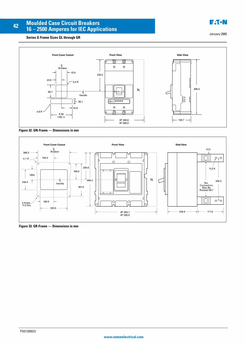
January 2005
42 Moulded Case Circuit Breakers16 – 2500 Amperes for IEC ApplicationsSeries G Frame Sizes GL through GR
Figure 32. GN-Frame — Dimensions in mm
Figure 33. GR-Frame — Dimensions in mm
235.0
CLBreaker
Front ViewFront Cover Cutout
406.4
87.4
6.4 R
Side View
CLHandle
139.73P 209.64P 280.0
43.6
96.7
38.1
6.38(162.1)
81.04.8 R
N
368.3
184.2
129.5
196.9
R4.1
Front ViewFront Cover Cutout
CLBreaker
406.4
209.6
3P 393.74P 280.0
333.5
166.9
246.4
381.0
4 Holes11.2 Dia.
CLHandle
330.2
57.2
TeeConnectors
May BeRotated 90
171.5228.6
Side View
11.2 R
N
PG0120002U
www.eatonelectrical.com
EE MCCB Series G PG Reprint 20/1/05 4:21 pm Page 42

EE MCCB Series G PG Cov reprint 20/1/05 4:20 pm Page 3

Series G
Moulded Case Circuit Breakers
Product Guide – Second Edition
© 2004 Eaton Electric LimitedAll rights reserved
Printed in UKForm No PG0120002UJanuary 2005
Eaton Electric LimitedReddings Lane
Birmingham B11 3EZ
United Kingdom
Customer Support Centre
Tel: +44 (0)8700 545 333
Fax: +44 (0)8700 540 333
email: [email protected]
Eaton Electric NV
PO Box 23
7550 AA Hengelo
The Netherlands
Customer Support Centre
Tel: +31 (0)74 246 7066
Fax: +31 (0)74 246 7070
email: [email protected]
Eaton’s Electrical business is a global leader in electrical control, powerdistribution, and industrial automation products and services. Throughadvanced product development, world-class manufacturing methods, and global engineering services and support, Eaton’s Electrical businessprovides customer-driven solutions under brand names such as Cutler-Hammer®, Durant®, Heinemann®, Holec® and MEM®, whichglobally serve the changing needs of the industrial, utility, lightcommercial, residential, and OEM markets. For more information, visitwww.EatonElectrical.com.
Eaton Corporation is a diversified industrial manufacturer with 2003 salesof $8.1 billion. Eaton is a global leader in fluid power systems andservices for industrial, mobile and aircraft equipment; electrical systemsand components for power quality, distribution and control; automotiveengine air management systems and powertrain controls for fueleconomy; and intelligent drivetrain systems for fuel economy and safetyin trucks. Eaton has 54,000 employees and sells products to customers inmore than 100 countries. For more information, visit www.eaton.com.
• Up to 690 Vac
• 18kA to 100kA Icu• 16-2500 Amperes
• IEC 60947-2
Safety, Reliability
and Performance
verified with the
KEMA KEUR mark
EE MCCB Series G PG Cov reprint 20/1/05 4:20 pm Page 1