Series B 480V 60Hz User Manual - mtecorp.com upon receipt, ... 0 to 3300 Feet above sea level. ......
58
© 2006 MTE Corporation PART NO. INSTR - 015 REL. 060628 M T E C o r p o r a t i o n MATRIX FILTER ™ SERIES B 380-415 Volts, 50HZ USER MANUAL
Transcript of Series B 480V 60Hz User Manual - mtecorp.com upon receipt, ... 0 to 3300 Feet above sea level. ......
© 2006 MTE Corporation
PART NO. INSTR - 015 REL. 060628
M T E C o r p o r a t i o n
MATRIX FILTER ™ SERIES B 380-415 Volts, 50HZ
USER MANUAL


IMPORTANT USER INFORMATION
NOTICE
The MTE Corporation Matrix Filter is designed for harmonic mitigation of six pulse inverter drives supplying variable torque loads in a wide variety of applications. The suitability of this filter for a specific application must therefore be determined by the customer. In no event will MTE Corporation assume responsibility or liability for any direct or consequential damages resulting from the use or application of this filter. Nor will MTE Corporation assume patent liability with respect to the use of information, circuits or equipment described in this instruction manual.


TABLE OF CONTENTS TABLE OF CONTENTS .......................................................................................................... 0
1. IMPORTANT SAFETY INFORMATION ............................................................................. 1
2. INTRODUCTION ................................................................................................................ 2
3. MODEL CODE PART NUMBER CONFIGURATION.......................................................... 3
4. SPECIFICATIONS.............................................................................................................. 4
RATINGS ................................................................................................................................ 4
SERVICE CONDITIONS ............................................................................................................. 4
PERFORMANCE....................................................................................................................... 5
WEIGHTS ............................................................................................................................... 6
ALTITUDE DERATING CURVE .................................................................................................. 10
5. INSTALLATION INSTRUCTIONS..................................................................................... 11
FILTER INSTALLATION ............................................................................................................ 11
MOUNTING DIMENSIONS AND OUTLINE DRAWINGS .................................................................. 12
Panel Mounted Filters ..................................................................................................... 12
NEMA 1, 2 & 3R cabinets................................................................................................ 24
POWER WIRING CONNECTION................................................................................................ 32
INPUT AND OUTPUT TERMINAL SPECIFICATIONS....................................................................... 33
OVER TEMPERATURE SWITCH................................................................................................ 34
INTERCONNECTION DIAGRAM ................................................................................................. 35
Terminal Locations.......................................................................................................... 39
6. FILTER DESCRIPTION.................................................................................................... 48
380 - 415 VAC 50HZ BLOCK DIAGRAM .................................................................................. 49
7. STARTUP.......................................................................................................................... 50
8. TROUBLESHOOTING ...................................................................................................... 51

1 Part No. INSTR-015 REL. 060628
1. IMPORTANT SAFETY INFORMATION
WARNING
ONLY A QUALIFIED ELECTRICIAN CAN CARRY OUT THE ELECTRICAL INSTALLATION OF THIS FILTER
WARNING
High voltage is used in the operation of this filter. Use Extreme caution to avoid contact with high voltage when operating, installing or repairing this filter. INJURY OR DEATH MAY RESULT IF SAFETY PRECAUTIONS ARE NOT OBSERVED. After removing power, allow at least five minutes to elapse and verify that the capacitors have discharged to a safe level before contacting internal components. Connect a DC voltmeter across the capacitor terminals or terminals 1, 2 and 3 on terminal block 1TB. Start with the meter on the highest scale and progressively switch to a lower scale as the indicated voltage falls below the maximum value of the scale used.
WARNING
The opening of the branch circuit protective device may be an indication that a fault current has been interrupted. To reduce the risk of fire or electrical shock, current-carrying parts and other components of the filter should be examined and replaced if damaged.
WARNING An upstream disconnect/protection device must be used as required by the National Electrical Code (NEC).
WARNING Even if the upstream disconnect/protection device is open, the drive down stream of the filter may feed back high voltage to the filter. The drive safety instructions must be followed. INJURY OR DEATH MAY RESULT IF THE DRIVE SAFETY PRECAUTIONS ARE NOT OBSERVED.
WARNING The filter must be grounded with a grounding conductor connected to all grounding terminals.
WARNING Only spare parts obtained from MTE Corporation or an authorized MTE distributor can be used.

2 Part No. INSTR-015 REL. 060628
2. INTRODUCTION This manual was specifically developed to assist in the installation, interconnection and operation of the MTE Corporation Matrix Filter. This manual is intended for use by personnel experienced in the operation and maintenance of electronic drives. Because of the high voltages required by the filter and drive and the potential dangers presented by rotating machinery, it is essential that all personnel involved in the operation and maintenance of this filter know and practice the necessary safety precautions for this type of equipment. Personnel should read and understand the instructions contained in this manual before installing, operating or servicing the filter and the drive to which the filter is connected. Upon Receipt of this Filter: The MTE Matrix Filter has been subjected to demanding factory tests before shipment. Carefully inspect the shipping container for damage that may have occurred in transit. Then unpack the filter and carefully inspect for any signs of damage. Save the shipping container for future transport of the filter. In the event of damage, please contact and file a claim with the freight carrier involved immediately.
If the equipment is not going to be put into service upon receipt, cover and store the filter in a clean, dry location. After storage, ensure that the equipment is dry and that no condensation has accumulated on the internal components of the filter before applying power.
Repair/Exchange Procedure MTE Corporation requires a Returned Material Authorization Number before it can accept any filters that qualify for return or repair. If problems or questions arise during installation, setup, or operation of the filter, please call us for assistance at: Phone: 262-253-8200 ex 148 FAX: 262-253-8222

3 Part No. INSTR-015 REL. 060628
3. Model Code Part Number Configuration
Model Number Code System: M X X X _ _ _ _ Y X X X X Matrix Filter Designator 5% or 8% THID Mechanical Configurations
P = Panel Mount G = NEMA 1 or 2 W = NEMA 3R
Enclosure Size B CAB-17B or CAB-002 C CAB-20B or CAB-003 D CAB-30B or CAB-004 E CAB-42B or CAB-005 F CAB-48B or CAB-006 Current Rating
(i.e. 006 is 6 Amps) 786 amps max
Voltage: A 208-240V, 60Hz B 240V, 50Hz C 380-415V, 50Hz D 480V, 60Hz E 600V, 60Hz
Options

4 Part No. INSTR-015 REL. 060628
4. SPECIFICATIONS Ratings
Table 1
380 - 415 VAC, 50 Hz SERIES B Filter Ratings THID Rating 8% 5%
Maximum Output Amps RMS
Efficiency (Typical)
(%)
Power Dissipation @ Rated Current
(Typical) (Watts)
Efficiency(Typical)
(%)
Power Dissipation @ Rated Current
(Typical) (Watts)
6 97.2 139 97.4 132 8 97.5 164 97.6 161
11 97.8 200 97.8 197 14 98.0 233 98.0 232 21 98.3 299 98.3 294 27 98.4 351 98.5 343 34 98.6 406 98.6 399 44 98.7 479 98.7 472 52 98.8 539 98.8 533 66 98.9 626 98.9 621 83 98.9 740 98.9 735
103 99.0 850 99.0 844 128 99.1 964 99.1 959 165 99.2 1145 99.2 1143 208 99.2 1361 99.2 1355 240 99.3 1498 99.2 1493 320 99.3 1838 99.3 1829 403 99.4 2110 99.4 2098 482 99.4 2393 99.4 2371 636 99.4 2978 99.4 2929 786 99.5 3432 99.5 3402
Service Conditions
Load: 6 pulse variable torque rectifier only Input voltage: 380-415 VAC +/- 10%, 50 + 0.75 Hz, 3 phase Input voltage line unbalance: 1% maximum Maximum source impedance: 6.00% Minimum source impedance: 1.5% Service Factor: 1.00

SPECIFICATIONS - continued
5 Part No. INSTR-015 REL. 060628
Ambient Temperature (Operating)
Enclosed Filters: -40 to +40 degrees C Open Panel Filters: -40 to +50 degrees C
Storage Temperature: -40 to +90 degrees C Altitude: 0 to 3300 Feet above sea level. Refer to Figure 6 for altitude derating. Relative Humidity: 0 to 95% non-condensing Agency Approvals UL and cUL listed to UL508 and CSA-C22.2 No 14-95 File E180243 (3 – 1000 HP, 120VAC through 600 VAC 50, 50/60, 60 Hz Three Phase Performance Total Harmonic Current Distortion: Eight Percent Filter: 8% typical at full load 12% maximum no load to full load Five Percent Filter: 5% typical at full load 8% maximum no load to full load Standby Current:
Without Optional Capacitor Contactor: 70% of the full load capacitor current listed in Table 3 With Optional Capacitor Contactor: Refer to Drive Users Manual
8% 5%
FILTER VOLTAGE REGULATION 380 - 415 380 - 415
MAXIMUM OUTPUT VOLTAGE AT NO LOAD
RMS PEAK
397 560
397 560
MINIMUM OUTPUT VOLTAGE AT FULL LOAD
RMS PEAK
364 475
364 475
*MAXIMUM PCC VOLTAGE WITH 6% SOURCE IMPEDANCE
RMS PEAK
388 548
388 548
*Note: PCC is the point of common coupling with the power distribution system

SPECIFICATIONS - continued
6 Part No. INSTR-015 REL. 060628
Table 2 Weights
380 - 415 Volt, 50 Hz Series B Matrix Filter Weights
Open Panel General Purpose
NEMA 1, 2, 3R Industrial NEMA 1
THID THID THID Output Amps RMS 8%
Weight Lbs
5% Weight
Lbs
8% Weight
Lbs
5% Weight
Lbs
8% Weight
Lbs
5% Weight
Lbs 6 27 38 83 94 62 73
8 30 40 85 96 65 75
11 35 45 95 105 70 80
14 35 45 95 105 80 90
21 45 55 105 115 85 95
27 50 65 135 150 100 115
34 90 105 160 175 145 160
44 90 105 160 175 125 140
52 105 135 170 200 235 265
66 125 155 300 330 270 300
83 210 265 360 410 335 390
103 210 265 360 410 335 390
128 225 275 390 440 350 400
165 275 310 425 485 485 520
208 275 325 430 480 490 540
240 310 410 510 610 535 635
320 660 760 750 850 1200 ---
403 715 840 845 970 1275 ---
482 780 945 905 1060 1375 ---
636 1525 1775 1350 1675 --- ---
786 1800 2100 1550 1925 --- ---
SPECIFICATIONS - continued
7 Part No. INSTR-015 REL. 060628
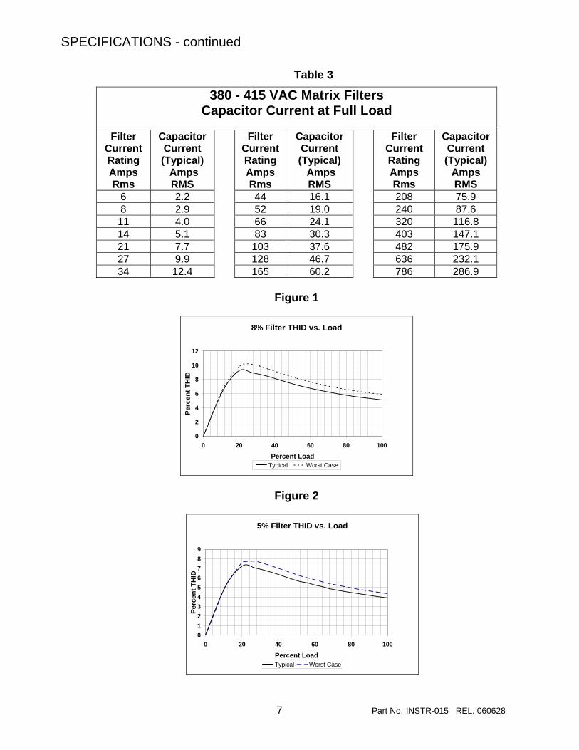
Table 3
380 - 415 VAC Matrix Filters Capacitor Current at Full Load
Filter
Current Rating Amps Rms
Capacitor Current (Typical) Amps RMS
Filter Current Rating Amps Rms
Capacitor Current (Typical) Amps RMS
Filter Current Rating Amps Rms
Capacitor Current (Typical)
Amps RMS
6 2.2 44 16.1 208 75.9 8 2.9 52 19.0 240 87.6
11 4.0 66 24.1 320 116.8 14 5.1 83 30.3 403 147.1 21 7.7 103 37.6 482 175.9 27 9.9 128 46.7 636 232.1 34 12.4 165 60.2 786 286.9
Figure 1
8% Filter THID vs. Load
0
2
4
6
8
10
12
0 20 40 60 80 100
Percent Load
Perc
ent T
HID
Typical Worst Case
Figure 2
5% Filter THID vs. Load
0123456789
0 20 40 60 80 100
Percent Load
Perc
ent T
HID
Typical Worst Case

SPECIFICATIONS - continued
8 Part No. INSTR-015 REL. 060628
Figure 3
8% Matrix Filter Typical Harmonic Spectrum For 100 % Load
0
1
2
3
4
5 7 11 13 17 19 23 25
Harmonic Order
Har
mon
ic c
urre
nt %
Figure 4
5% Matrix Filter Typical Harmonic Spectrum For 100% Load
0
1
2
3
4
5 7 11 13 17 19 23 25
Harmonic order
Har
mon
ic C
urre
nt %
SPECIFICATIONS - continued
9 Part No. INSTR-015 REL. 060628
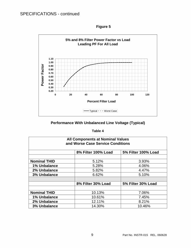
Figure 5
5% and 8% Filter Power Factor vs LoadLeading PF For All Load
0.200.300.400.500.600.700.800.901.001.10
0 20 40 60 80 100 120
Percent Filter Load
Pow
er F
acto
r
Typical Worst Case
Performance With Unbalanced Line Voltage (Typical)
Table 4
All Components at Nominal Values and Worse Case Service Conditions
8% Filter 100% Load 5% Filter 100% Load Nominal THID 5.12% 3.93% 1% Unbalance 5.28% 4.06% 2% Unbalance 5.82% 4.47% 3% Unbalance 6.62% 5.10% 8% Filter 30% Load 5% Filter 30% Load Nominal THID 10.13% 7.06% 1% Unbalance 10.61% 7.45% 2% Unbalance 12.11% 8.21% 3% Unbalance 14.30% 10.46%

SPECIFICATIONS - continued
10 Part No. INSTR-015 REL. 060628
Figure 6 Altitude Derating Curve
1.05
1.00
0.95
0.90
0.85
0.80
0.75
0.70
0 3300 6600 9900 13200 16500
CU
RR
ENT
DER
ATI
NG
FA
CTO
R
ALTITUDE (FEET)

11 Part No. INSTR-015 REL. 060628
5. INSTALLATION INSTRUCTIONS Filter Installation Matrix Filters are supplied in the following mechanical configurations:
Panel mounted assemblies
Floor mounted general purpose NEMA 1, 2, & 3R cabinets
Industrial style NEMA 1 cabinets with hinged doors.
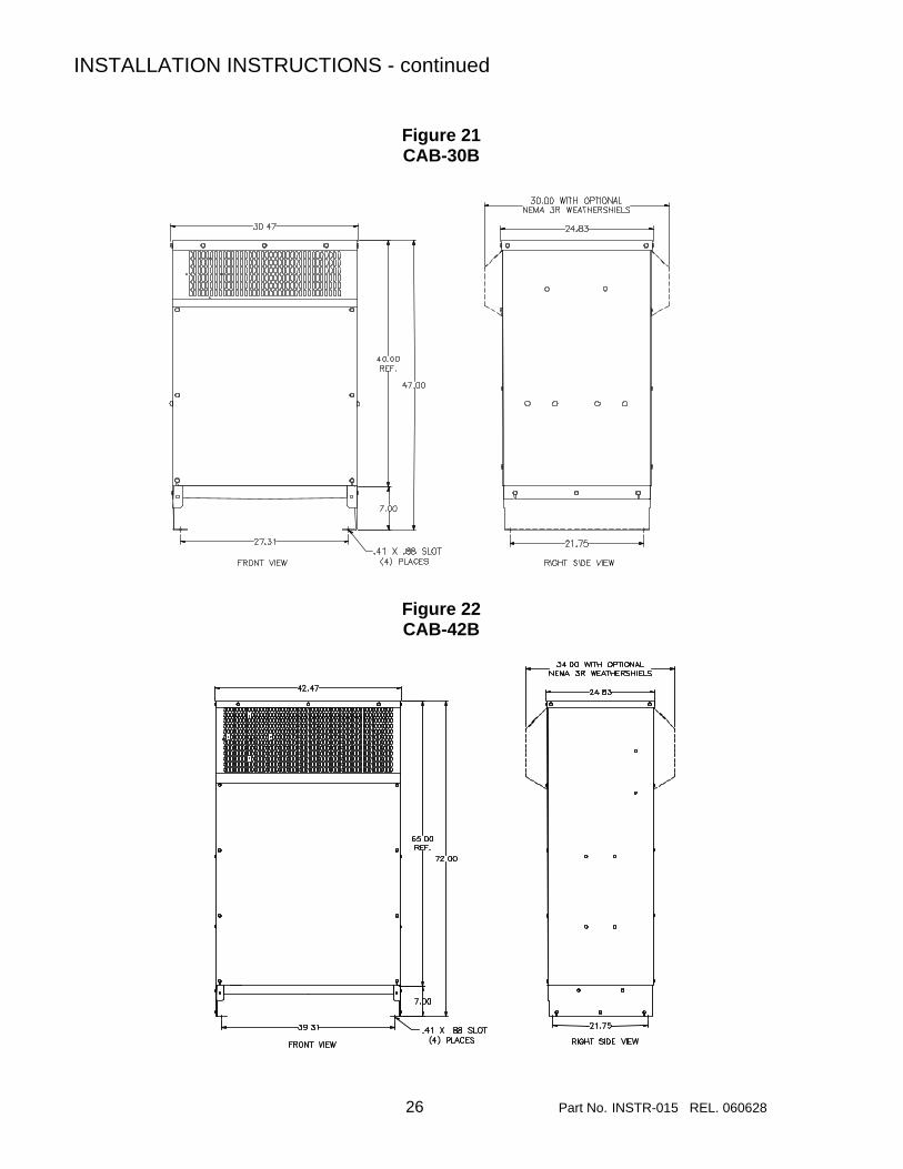
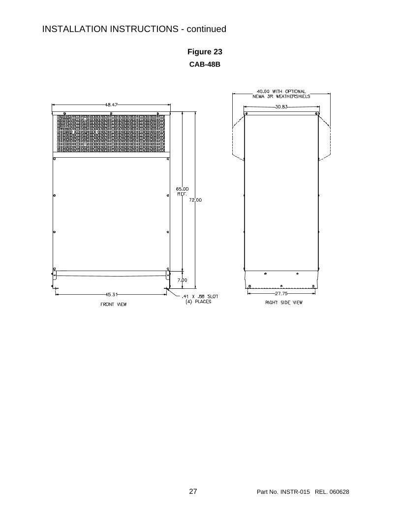
Panel mounted filters are designed for mounting in the vertical plane in the customer’s enclosure. Include the power dissipation of the filter along with all the other components located in the panel to determine the internal temperature rise and cooling requirements of the enclosure. Allow a minimum side clearance of four (4) inches and a vertical clearance of six (6) inches for proper heat dissipation and access. Figure 7 through Figure 17 contain outline drawings for the various ratings and show proper mounting orientation. For 5% filters, Model numbers beginning with M5, refer to Figure 18 and Table 5 for the dimensions of the separately mounted input reactor. Select a well ventilated, dust-free area away from direct sunlight, rain or moisture. Do not install in or near a corrosive environment. Avoid locations where the filter would be subjected to excessive vibrations. General purpose NEMA 1, 2, and 3R enclosed filters are designed for floor mounting in the vertical plane in an environment suitable for the enclosure type. Do not install in or near a corrosive environment. Avoid locations where the filter would be subjected to excessive vibrations. Allow a minimum side and back clearance of eight (8) inches and front clearance of thirty-six (36) inches for proper heat dissipation and access. Table 6 will direct you to the appropriate outline drawings shown in Figure 19 through Figure 23. Industrial style NEMA 1 enclosed filters are designed for wall and floor mounting in the
vertical plane. Do not install in or near a corrosive environment. Avoid locations where the filter would be subjected to excessive vibrations. For wall mounted enclosures allow a minimum side clearance of eight (8) inches and front clearance of forty-eight (48) inches for proper heat dissipation and access. For floor mounted enclosures allow a minimum side and back clearance of eight (8) inches and front clearance of forty-eight (48) inches for proper heat dissipation and access. Table 7 will direct you to the appropriate outline drawings shown in Figure 24 through Figure 28.

INSTALLATION INSTRUCTIONS - continued
12 Part No. INSTR-015 REL. 060628
Mounting Dimensions And Outline Drawings Panel Mounted Filters
Figure 7 6 – 21 Amps, 380 - 415 VAC 50Hz Outline Drawing
All dimensions are in inches

INSTALLATION INSTRUCTIONS - continued
13 Part No. INSTR-015 REL. 060628
Figure 8 27 Amps, 380 - 415 VAC 50Hz Outline Drawing
All dimensions are in inches

INSTALLATION INSTRUCTIONS - continued
14 Part No. INSTR-015 REL. 060628
Figure 9
34 - 66 Amps, 380 - 415 VAC 50Hz Outline Drawing
All dimensions are in inches
REACTOR ASSEMBLY
CAPACITOR ASSEMBLY
NOTE: CAPACITOR ASSEMBLY MAY BE MOUNTED IN EITHER PLANE

INSTALLATION INSTRUCTIONS - continued
15 Part No. INSTR-015 REL. 060628
Figure 10 83 – 128 Amps, 380 - 415 VAC 50Hz Outline Drawing
All dimensions are in inches
REACTOR ASSEMBLY
CAPACITOR ASSEMBLY
NOTE: CAPACITOR ASSEMBLY MAY BE MOUNTED IN EITHER PLANE

INSTALLATION INSTRUCTIONS - continued
16 Part No. INSTR-015 REL. 060628
Figure 11 165 – 208 Amps, 380 - 415 VAC 50Hz Outline Drawing
All dimensions are in inches
REACTOR ASSEMBLY
NOTE: TWO CAPACITOR ASSEMBLIES REQUIRED
NOTE: CAPACITOR ASSEMBLY MAY BE MOUNTED IN EITHER PLANE

INSTALLATION INSTRUCTIONS - continued
17 Part No. INSTR-015 REL. 060628
Figure 12 240 Amps, 380 - 415 VAC 50Hz Reactor Assembly Outline Drawing
All dimensions are in inches
REACTOR ASSEMBLY

INSTALLATION INSTRUCTIONS - continued
18 Part No. INSTR-015 REL. 060628
Figure 13 240 Amps, 380 - 415 VAC 50Hz Capacitor Assembly Outline Drawing
All dimensions are in inches
NOTE: ONE OF EACH CAPACITOR ASSEMBLY REQUIRED
NOTE: CAPACITOR ASSEMBLY MAY BE MOUNTED IN EITHER PLANE

INSTALLATION INSTRUCTIONS - continued
19 Part No. INSTR-015 REL. 060628
Figure 14 320 – 482 Amps, 380 - 415 VAC 50Hz Vertical Mounting Outline Drawing
All dimensions are in inches

INSTALLATION INSTRUCTIONS - continued
20 Part No. INSTR-015 REL. 060628
Figure 15 320 – 482 Amps, 380 - 415 VAC 50Hz Horizontal Mounting Outline Drawing
All dimensions are in inches
380 - 415 VAC Matrix Filters rated 320 amps through 786 amps are constructed from a reactor assembly and a capacitor assembly. These assemblies are designed to be mounted vertically. The reactor assembly may be mounted above the capacitor assembly as shown in Figure 14 or the assemblies may be mounted separately as shown in Figure 15. The capacitor assembly should be located in the lowest temperature regions of the enclosure – generally toward the bottom. For 380 – 415 VAC Matrix Filters rated 636 amps through 786 amps see Figures16 and 17. The reactor and capacitor assemblies are shipped vertically oriented bolted and banded front-to-back to a common pallet.

INSTALLATION INSTRUCTIONS - continued
21 Part No. INSTR-015 REL. 060628
Figure 16 636 – 786 Amps, 380 - 415 VAC 50Hz Vertical Mounting Outline Drawing
All dimensions are in inches

INSTALLATION INSTRUCTIONS - continued
22 Part No. INSTR-015 REL. 060628
Figure 17 636 – 786 Amps, 380 - 415 VAC 50Hz Capacitor Assembly Outline Drawing
All dimensions are in inches

INSTALLATION INSTRUCTIONS - continued
23 Part No. INSTR-015 REL. 060628
Figure 18
5% PANEL MOUNTED FILTER INPUT REACTOR MOUNTING DIMENSIONS
TABLE 5
FILTER RATING AMPS
A Inches
B Inches
C Inches
D Inches
E Inches
F Inches
WEIGHT LBS
6 4.4 4.1 2.8 2.0 1.44 0.281 4 8 6.0 5.0 3.4 2.62 2.0 0.281 11
11 6.0 4.8 3.0 2.10 2.0 0.281 7 14 6.0 5.0 3.3 2.10 2.0 0.281 9 21 6.0 5.3 3.3 2.10 2.0 0.281 9 27 7.3 5.8 3.5 2.35 3.0 0.390 14 34 7.3 5.8 4.0 2.75 3.0 0.390 14 44 7.3 5.8 4.0 2.60 3.0 0.390 16 52 9.0 7.4 4.8 3.16 3.0 0.38 x 0.75 28 66 9.0 7.3 5.3 3.16 3.0 0.38 x 0.75 24 83 10.8 8.5 6.5 3.47 3.63 0.38 x 0.75 51
103 10.8 8.5 6.3 3.47 3.63 0.38 x 0.75 43 128 11.0 8.5 7.0 3.46 3.63 0.38 x 0.75 47 165 9.0 7.1 6.4 3.16 3.0 0.38 x 0.75 29 208 11.0 8.5 7.0 3.47 3.63 0.38 x 0.75 51 240 10.8 8.5 10.0 5.91 3.63 0.38 x 0.75 100 320 15.0 11.4 10.3 5.16 4.60 0.56 x 1.0 106 403 14.8 11.3 11.0 5.88 4.60 0.56 x 1.0 125 482 15.5 11.3 12.1 6.76 4.60 0.56 x 1.0 155 636 15.5 11.3 12.5 8.0 4.60 0.56 x 1.0 250 786 22.0 16.5 14.0 8.01 7.20 0.56 x 1.0 310

INSTALLATION INSTRUCTIONS - continued
24 Part No. INSTR-015 REL. 060628
Mounting Dimensions and outline drawings for floor mounted general purpose
NEMA 1, 2 & 3R cabinets
Table 6
General Purpose Cabinets NEMA 1, 2, & 3R
Filter Output Rating Amps.
Cabinet Part Number
6 CAB-17B 8 CAB-17B
11 CAB-17B 14 CAB-17B 21 CAB-20B 27 CAB-20B 34 CAB-20B 44 CAB-20B 52 CAB-20B 66 CAB-30B 83 CAB-30B
103 CAB-30B 128 CAB-30B 165 CAB-30B 208 CAB-30B 240 CAB-30B 320 CAB-42B 403 CAB-42B 482 CAB-42B 636 CAB-48B 786 CAB-48B

INSTALLATION INSTRUCTIONS - continued
25 Part No. INSTR-015 REL. 060628
Figure 19 CAB-17B
Figure 20 CAB-20B
INSTALLATION INSTRUCTIONS - continued
26 Part No. INSTR-015 REL. 060628
Figure 21 CAB-30B
Figure 22 CAB-42B
INSTALLATION INSTRUCTIONS - continued
27 Part No. INSTR-015 REL. 060628
Figure 23 CAB-48B

INSTALLATION INSTRUCTIONS - continued
28 Part No. INSTR-015 REL. 060628
Mounting dimensions and outline drawings for wall and floor mounted NEMA 1 cabinets follow.
Table 7
NEMA 1 Industrial Style Enclosures
Filter Output Rating Amps.
Cabinet Part Number
6 Cabinet-002 8 Cabinet-002
11 Cabinet-002 14 Cabinet-002 21 Cabinet-002 27 Cabinet-003 34 Cabinet-003 44 Cabinet-003 52 Cabinet-004 66 Cabinet-004 83 Cabinet-004
103 Cabinet-004 128 Cabinet-004 165 Cabinet-005 208 Cabinet-005 240 Cabinet-005 320 Cabinet-006* 403 Cabinet-006* 482 Cabinet-006* 636 N/A 786 N/A
*Floor Mounted

INSTALLATION INSTRUCTIONS - continued
29 Part No. INSTR-015 REL. 060628
Figure 24
Cabinet-002
Figure 25
Cabinet-003

INSTALLATION INSTRUCTIONS - continued
30 Part No. INSTR-015 REL. 060628
Figure 26 Cabinet-004
Figure 27 Cabinet-005

INSTALLATION INSTRUCTIONS - continued
31 Part No. INSTR-015 REL. 060628
Figure 28
Cabinet-006
Note: For 5% filters rated 320 Amps to 482 Amps a separately mounted input reactor is required. Refer to Figure 18 for mounting dimensions.
INSTALLATION INSTRUCTIONS - continued
32 Part No. INSTR-015 REL. 060628
Power Wiring Connection
WARNING Input and output power wiring to the filter should be performed by authorized personnel in accordance with the NEC and all local electrical codes and regulations. Verify that the power source to which the filter is to be connected is in agreement with the nameplate data on the filter. A fused disconnect switch or circuit breaker should be installed between the filter and its source of power in accordance with the requirements of the NEC and all local electrical codes and regulations. Refer to the drive user manual for selection of the correct fuse rating and class. The filter is suitable for use on a circuit capable of delivering not more than 100,000 rms symmetrical amperes at 380 - 415 volts when protected by J , T or RK1 class fuses. or a circuit breaker. For panel mounted filter applications rated 27 amperes and below, interconnection between the filter, its power source, and the drive is shown in Figure 29. Refer to the drive user manual for instructions on interconnecting the drive and motor and the correct start-up procedures for the drive. The filter is designed for use with copper conductors with a minimum temperature rating of 75 degrees C. Table 8 lists the wire range and terminal torque requirements for the power input and output connections by horsepower rating. For panel mounted filters rated 34 amperes or more, the filter reactors are supplied on a sub-panel and the filter capacitors are supplied on one or more assembles. Refer to Figure 30 for the interconnection diagram. The capacitor assembly should be located in the lowest temperature regions of the enclosure – generally toward the bottom – and the reactor
assembly may be located in any region where the ambient temperature does not exceed 50 degrees C. Size the conductors interconnecting the reactor and capacitor assemblies to carry the current shown in Table 3. For terminal specifications on the capacitor assembly, refer to Table 10. For filters supplied in general purpose NEMA 1, 2 & 3R cabinets, interconnection between the filter, its power source, and the drive is shown in Figure 31. Refer to Figures 33 to 36 for the location of input, output, ground and over temperature switch terminals. Refer to the drive user manual for instructions on interconnecting the drive and motor and the correct start-up procedures for the drive. For filters supplied in industrial style NEMA 1 cabinets, interconnection between the filter, its power source and the drive is shown in Figure 32. Refer to Figures 37 to 41 for the location of input, output, ground and over temperature switch terminals. Refer to the drive user manual for instructions on interconnecting the drive and motor and the correct start-up procedures for the drive. Grounding and Ground Fault Protection The filter must always be grounded with a grounding conductor connected to all ground terminals. Due to high leakage currents associated with variable frequency drives, ground fault protective devices do not necessarily operate correctly when placed ahead of a matrix filter feeding a drive. When using this type of device, its function should be tested in the actual installation.

INSTALLATION INSTRUCTIONS - continued
33 Part No. INSTR-015 REL. 060628
Table 8
Input and Output Terminal Specifications
Filter Rating(Amps) Input Terminals Output Terminals
Wire Range (AWG)
Terminal Torque (in-lbs)
Wire Range (AWG)
Terminal Torque (in-lbs)
6 22 -14 4.5 22 – 14 4.5 8
11 22 - 14 4.5 22 – 14 4.5 14 22 - 14 4.5 22 – 5 16 21 22 - 5 16 22 – 5 16 27 22 - 5 16 22 – 5 16 34 22 - 5 16 18 – 4 20 44 22 - 5 16 18 – 4 20 52 18 – 4 20 18 – 4 20
66 18 – 4 20 6-4 2-0
45 50
83 6-4 2-0
45 50
6-4 2-0
45 50
103 6-4 2-0
45 50
6-4 2-0
45 50
128 6-4 2-0
45 50
6-4 2-0
45 50
165 6-4 2-0
45 50 2-0000 150
208 2 – 0000 150 2 – 0000 150 240 2 – 0000 150 2 – 0000 150
320 2-0000 150
00 000-0000
250-350 MCM 500 MCM
180 250 325 375
403
00 000-0000
250-350 MCM 500 MCM
180 250 325 375
00 000-0000
250-350 MCM 500 MCM
180 250 325 375
482
00 000-0000
250-350 MCM 500 MCM
180 250 325 375
00 000-0000
250-350 MCM 500 MCM
180 250 325 375
636 NA NA NA NA 786 NA NA NA NA

INSTALLATION INSTRUCTIONS - continued
34 Part No. INSTR-015 REL. 060628
Over Temperature Switch
Table 9
TYPE BI – METAL THERMAL SWITCH
CONTACT (NC) NORMALLY CLOSED Slow break / slow make
RATINGS
6A 120 VAC RESISTIVE 3A 240 VAC RESISTIVE 8A 12 VDC RESISTIVE 4A 24 VDC RESISTIVE
5A 120 VAC INDUCTIVE 2.5A 240 VAC INDUCTIVE
TEMPERATURE CONTACTS Open at 180°C +/- 5

INSTALLATION INSTRUCTIONS - continued
35 Part No. INSTR-015 REL. 060628
Figure 29
Panel Mounted Filters 6 – 27 Amps, 380 - 415 VAC 50Hz
Interconnection Diagram

INSTALLATION INSTRUCTIONS - continued
36 Part No. INSTR-015 REL. 060628
Figure 30 Panel Mounted Filters 34 – 786 Amps 380 -415 VAC 50Hz
Interconnection Diagram

INSTALLATION INSTRUCTIONS - continued
37 Part No. INSTR-015 REL. 060628
Table 10 Capacitor Assembly Terminal Specifications
Filter Rating (Amps) Capacitor Terminals NOTE: Two terminals per phase
Wire Range (AWG) Terminal Torque (in lbs)
52 – 240
14 – 10 8
4 – 6 1/0 – 3
35 40 45 50
320 - 482 6-00
120
Figure 31 Filters Mounted in General Purpose NEMA 1, 2 & 3R Cabinets 6 – 786 Amps, 380 - 415 VAC 50 Hz Interconnection Diagrams

INSTALLATION INSTRUCTIONS - continued
38 Part No. INSTR-015 REL. 060628
Figure 32
Filters Mounted in Industrial Style Cabinets 6 – 482 Amps, 380 - 415 VAC 50Hz
Interconnection Diagram

INSTALLATION INSTRUCTIONS - continued
39 Part No. INSTR-015 REL. 060628
Figure 33 6 – 14 Amps, 380 - 415 VAC 50Hz General Purpose Cabinet
Terminal Locations
FRONT VIEW
See Figure 31 for Interconnection Diagram
INSTALLATION INSTRUCTIONS - continued
40 Part No. INSTR-015 REL. 060628
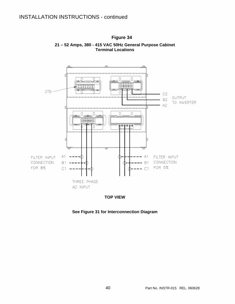
Figure 34 21 – 52 Amps, 380 - 415 VAC 50Hz General Purpose Cabinet
Terminal Locations
TOP VIEW
See Figure 31 for Interconnection Diagram

INSTALLATION INSTRUCTIONS - continued
41 Part No. INSTR-015 REL. 060628
Figure 35 66 – 240 Amps, 380 - 415 VAC 50Hz General Purpose Cabinet
Terminal Locations
TOP VIEW
See Figure 31 for Interconnection Diagram

INSTALLATION INSTRUCTIONS - continued
42 Part No. INSTR-015 REL. 060628
Figure 36 320 – 786 Amps, 380 - 415 VAC 50Hz General Purpose Cabinet
Terminal Locations
FRONT VIEW
See Figure 31 for Interconnection Diagram

INSTALLATION INSTRUCTIONS - continued
43 Part No. INSTR-015 REL. 060628
Figure 37
6 – 21 Amps, 380 - 415 VAC 50Hz Industrial Enclosures Terminal Locations
FRONT VIEW
See Figure 32 for Interconnection Diagram

INSTALLATION INSTRUCTIONS - continued
44 Part No. INSTR-015 REL. 060628
Figure 38 27 – 44 Amps, 380 - 415 VAC 50Hz Industrial Enclosures
Terminal Locations
FRONT VIEW
See Figure 32 for Interconnection Diagram

INSTALLATION INSTRUCTIONS - continued
45 Part No. INSTR-015 REL. 060628
Figure 39 52 – 128 Amps, 380 - 415 VAC 50Hz Industrial Enclosures
Terminal Locations
FRONT VIEW
See Figure 32 for Interconnection Diagram

INSTALLATION INSTRUCTIONS - continued
46 Part No. INSTR-015 REL. 060628
Figure 40 165 – 240 Amps, 380 - 415 VAC 50Hz Industrial Enclosures
Terminal Locations
FRONT VIEW
See Figure 32 for Interconnection Diagram

INSTALLATION INSTRUCTIONS - continued
47 Part No. INSTR-015 REL. 060628
Figure 41 320 – 482 Amps, 380 - 415 VAC 50Hz Industrial Enclosures
Terminal Locations
FRONT VIEW
See Figure 32 for Interconnection Diagram

48 Part No. INSTR-015 REL. 060628
6. FILTER DESCRIPTION The MTE Matrix Filter is a low pass filter containing proprietary technology, which makes it particularly useful for harmonic mitigation of adjustable speed drives. Figure 42 shows a block diagram of the filter. Three phase AC power is connected to the input section which contains a three phase AC reactor and circuitry which inhibits oscillation of the filter with the AC power system. The center leg consists of a series reactor and capacitor bank. Because of the capacitor bank the filter operates with leading power factor at all loads, but unlike trap filters the MTE Matrix Filter does not produce significant voltage rise at the point of common coupling with the power system. The standard 8% filter output section consists of an AC output reactor. The 5% filter is comprised of a standard 8% filter plus an additional input reactor. Matrix filters are suitable for use with AC and DC drives and they can be used in both regenerative and non-regenerative applications when properly selected. Filters for variable torque AC drives rated 7.5 Hp and above should be selected for a filter output current rating greater than or equal to the motor current rating. If the motor current rating is not available, use the NEC motor current rating. Filters for variable torque AC drives rated 2 – 5 Hp should be selected for a filter output current
rating greater than or equal to 105% of the motor current rating. If the motor current rating is not available, select on the basis of 105% of the NEC motor current rating. Filters for variable torque AC drives rated less than 1.5 Hp should be selected for an output current rating greater than or equal to 110% of the motor current rating or 110% OF the NEC motor current rating. For constant torque, AC and DC drive applications operating from six pulse rectifier front ends selected a filter current rating according to application engineering note “Matrix Filter Operation in Constant Torque Applications with Six Pulse Rectifiers” or consult MTE engineering. For phase controlled DC drive applications, select filter current rating per application note “Matrix Filter with Phase Controlled DC Drivers. Where a single filter is used to feed multiple drives, the output current rating of the filter should be selected to equal the total current rating of the individual drives when calculated according to the instructions above. Because the filter supplies harmonic currents required by the drive, linear loads (such as space heaters, incandescent lighting and AC motors operated across the line) should not be connected to the output of the filter.

FILTER DESCRIPTION - continued
49 Part No. INSTR-015 REL. 060628
Figure 42 380 - 415 VAC 50Hz Block Diagram

50 Part No. INSTR-015 REL. 060628
7. STARTUP Safety Precautions Before startup, observe the following warnings and instructions:
WARNING Internal components of the filter are at line potential when the filter is connected to the utility. This voltage is extremely dangerous and may cause death or severe injury if you come in contact with it.
WARNING After disconnecting the utility power, wait at least 5 minutes before doing any work on the filter connections. After removing power, allow at least five minutes to elapse and verify that the capacitors have discharged to a safe level before contacting internal components. Connect a DC voltmeter across the capacitor terminals or terminals 1, 2 and 3 on terminal block 1TB. Start with the meter on the highest scale and progressively switch to a lower scale as the indicated voltage falls below the maximum value of the scale used. Sequence of Operation 1. Read and follow safety precautions. 2. After installation, ensure that:
• All filter ground terminals are connected to ground.
• Power wiring to the utility, drive and motor is in accordance with the installation and connection instructions in Chapter 5.
3. Check that moisture has not condensed on the filter components. If moisture is present, do not proceed with startup until the moisture has been removed.
4. Disconnect the filter output from the drive. 5. Connect the filter to the utility.
WARNING Use extreme caution to avoid contact with line voltage when checking for power. INJURY OR DEATH MAY RESULT IF SAFETY PRECAUTIONS ARE NOT OBSERVED.
6. Confirm that line voltage is present at the
input terminals (A1, B1, C1) of the filter.
7. Confirm that line voltage is present at the output terminals (A2, B2, C2) of the filter.
8. Disconnect the filter from the utility. 9. Connect the filter output to the drive. 10. Refer to the drive user manual for the drive
startup procedure. Observe all safety instructions in the drive user manual.
WARNING
INJURY OR DEATH MAY RESULT IF THE DRIVE SAFETY PRECAUTIONS ARE NOT OBSERVED.
CAUTION Damage to equipment may occur if the drive startup procedures are not observed.

51 Part No. INSTR-015 REL. 060628
8. TROUBLESHOOTING
WARNING When properly installed, this equipment has been designed to provide maximum safety for operating personnel. However, hazardous voltages exist within the confines of the enclosure. Servicing should therefore be performed by qualified personnel only and in accordance with OSHA Regulations. To aid in troubleshooting, a block diagram is shown in Figure 42, and a list of potential problems and solutions are listed below.
WARNING
High voltage is used in the operation of this filter. Use Extreme caution to avoid contact with high voltage when operating, installing or repairing this filter. INJURY OR DEATH MAY RESULT IF SAFETY PRECAUTIONS ARE NOT OBSERVED. After removing power, allow at least five minutes to elapse and verify that the capacitors have discharged to a safe level before contacting internal components. Connect a DC voltmeter across the capacitor terminals or terminals 1, 2 and 3 on terminal block 1TB. Start with the meter on the highest scale and progressively switch to a lower scale as the indicated voltage falls below the maximum value of the scale used.
PROBLEM:
Line voltage is not present at the filter output terminals.
Possible cause: Power to the filter is turned off.
Solution: Turn power on.
Possible cause: One or more external line fuses are blown.
Solution: Verify the continuity of line fuses in all phases. Replace as necessary.
.

TROUBLESHOOTING - continued
52 Part No. INSTR-015 REL. 060628
PROBLEM:
Harmonic current distortion exceeds 8% on one or more phases at full load.
Possible cause: On filters rated 34 amps and above, the capacitor assembly has not been connected.
Solution: Check interconnection of capacitor assembly with reactor panel (Figure 30).
Possible cause: A capacitor has failed.
Solution: Inspect the tops of all capacitors for bowing. Replace failed capacitors.
Possible cause:
Solution
Source impedance is less than 1.5%.
Add a minimum 1.5% impedance line reactor to the filter input
Possible cause:
Solution
Input source voltage harmonic distortion.
Identify equipment causing harmonic voltage distortion and add filters as required or accept elevated THVD
Possible cause:
Solution:
Line voltage unbalance exceeds 1%.
Balance input line voltage to 1% or less.
PROBLEM:
Harmonic current distortion exceeds 5% on one or more phases at full load.
Possible cause: The input reactor required for a 5% filter was not installed. (See Figure 42.)
Solution: Install the required input reactor
Possible cause: On filters rated 34 amps and above, the capacitor assembly has not been connected.
Solution: Check interconnection of capacitor assembly with reactor panel (Figure 30).
Possible cause: A capacitor has failed.
Solution: Inspect the tops of all capacitors for bowing. Replace failed capacitors.

TROUBLESHOOTING - continued
53 Part No. INSTR-015 REL. 060628
PROBLEM:
Harmonic current distortion exceeds 5% on one or more phases at full load.
Possible cause:
Solution
Source impedance is less than 1.5%.
Add a minimum 1.5% impedance line reactor to the filter input
Possible cause:
Solution
Input source voltage harmonic distortion.
Identify equipment causing harmonic voltage distortion and add filters as required or accept elevated THVD
Possible cause:
Solution:
Line voltage unbalance exceeds 1%.
Balance input line voltage to 1% or less.
PROBLEM: Filter output voltage is not within specification
Possible cause: Filter input voltage is not within specification.
Solution: Check the AC input line voltage and verify that it is within tolerance. Refer to the filter service conditions and performance specifications in Chapter 3 for tolerances.
Possible cause: Source impedance is out of tolerance.
Solution: Verify that the source impedance is within tolerance. Refer to the filter service conditions and performance specifications in Chapter 4 for tolerances.