Series 17CA3000 CHLORALERTTM PLUS Multi-Gas...
10
- 1 - 325.7603.5 Series 17CA3000 CHLORALERT TM PLUS Multi-Gas Detector
-
Upload
nguyenduong -
Category
Documents
-
view
225 -
download
3
Transcript of Series 17CA3000 CHLORALERTTM PLUS Multi-Gas...

- 1 - 325.7603.5
Series 17CA3000CHLORALERTTM PLUSMulti-Gas Detector
325.7603.5 - 2 -
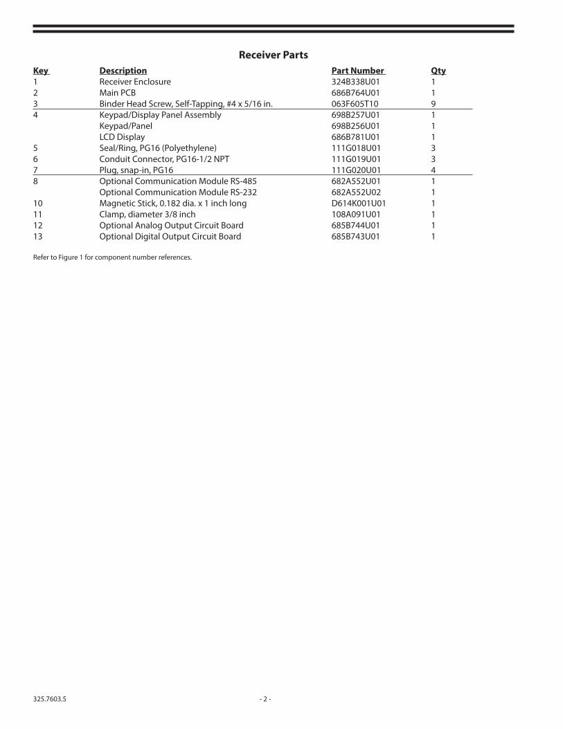
Receiver PartsKey Description Part Number Qty1 Receiver Enclosure 324B338U01 12 Main PCB 686B764U01 13 Binder Head Screw, Self-Tapping, #4 x 5/16 in. 063F605T10 94 Keypad/Display Panel Assembly 698B257U01 1 Keypad/Panel 698B256U01 1 LCD Display 686B781U01 15 Seal/Ring, PG16 (Polyethylene) 111G018U01 36 Conduit Connector, PG16-1/2 NPT 111G019U01 37 Plug, snap-in, PG16 111G020U01 48 Optional Communication Module RS-485 682A552U01 1 Optional Communication Module RS-232 682A552U02 110 Magnetic Stick, 0.182 dia. x 1 inch long D614K001U01 111 Clamp, diameter 3/8 inch 108A091U01 112 Optional Analog Output Circuit Board 685B744U01 113 Optional Digital Output Circuit Board 685B743U01 1
Refer to Figure 1 for component number references.

- 3 - 325.7603.5
Figu
re 1
- Re
ceiv
er P
arts
ON
TRO
LSA
PIT
ALCC
SETU
P0
QZ
ALAR
M
DATA
PRS
7
GHI
4
TUV
8
JKL
5
12
ABC
ENTE
R
WXY
9
MNO
6
LETT
ER
ACK
DEF
3

325.7603.5 - 4 -
Main Circuit BoardComponent Number Description Part Number QtyF1 Fuse, 1 amp, 250V (TR5) 151B058U02 1F401 Fuse, 3.15 amp, Time-Lag (TR5) 151B059U04 1F402 Fuse, 3.15 amp, Time-Lag (TR5) 151B059U04 1F403 Fuse, 3.15 amp, Time-Lag (TR5) 151B059U04 11 Main Printed Circuit Board 686B764U01 1Refer to Figure 2 for component number references.
Figure 2 - Main Circuit Board
1

- 5 - 325.7603.5
Figure 3 - Digital Output Board Assembly
Digital Output Option PCB Replacement PartsComponent Number Description Part Number QtyF1 through F6 Fuse, 3.15 amp, Time-Lag (TR5) 151B059U04 11 Digital Output Circuit Board (Option) 685B743U01 1Refer to Figure 3 for component number references.
1

325.7603.5 - 6 -
Figure 4 - Battery Box, Front View without Cover
Battery Box AccessoriesKey Description Part Number 1 Complete Battery Assembly 614S112U01 2 Fuse, 4 amp 151A052U013 Battery 167B027U01
Refer to Figure 4 for component number references.

- 7 - 325.7603.5
Figure 5 - Optional Analog Output Circuit Board, P/N 685B744U01
Figure 6 - Communication Module
Type Part NumberRS-485 682A552U01RS-232 682A552U02

325.7603.5 - 8 -
Sensor/Transmitter Assembly Key Description Part Number 1 E/C Sensor, CL2 640B029U01 E/C Sensor, SO2 640B030U012 6/32 x 1/8 Hex Socket 04F106AU203 Calibration Cap Assembly 274774 Chlorine Sensor - (0.0 to 5 ppm) 628B110U01 Chlorine Sensor - (0.0 to 10 ppm) 628B110U02 Chlorine Sensor - (0.0 to 50 ppm) 628B110U03 Sulfur Dioxide Sensor - (0.0 to 10 ppm) 628B111U01 Sulfur Dioxide Sensor - (0.0 to 20 ppm) 628B111U02 Sulfur Dioxide Sensor - (0.0 to 100 ppm) 628B111U035 Chlorine Sensor w/Sensor-Check - (0.0 to 5 ppm) 628B110U04 Chlorine Sensor w/Sensor-Check - (0.0 to 10 ppm) 628B110U05 Chlorine Sensor w/Sensor-Check - (0.0 to 50 ppm) 628B110U06 6 e/c Sensor with Sensor Check Chlorine 640B029U027 Sensor Check Assembly 641B227U01
Refer to Figure 7 for component number references.

- 9 - 325.7603.5
Figure 7 - Sensors
USING PARTS OTHER THAN GENUINE DNWT PARTS:
- CAN RESULT IN MALFUNCTION OF THE EQUIPMENT AND POTENTIALLY CAUSE SERIOUS PERSONAL AND ENVIRONMENTAL HEALTH AND SAFETY HAZARDS
- WILL VOID YOUR EQUIPMENT WARRANTY
- WILL VOID YOUR LIABILITY CLAIMS TO DNWT

325.7603.5 - 10 -OCT 2015
De Nora Water Technologies3000 Advance Lane Colmar, PA 18915 ph +1 215 997 4000 • fax +1 215 997 4062 web: www.denora.commail: [email protected]
®Registered Trademark. © 2015. All Rights Reserved.