Series 10 - Brook Cromptonbrookcrompton.com/upload/files/products/20121E_Series10.pdf · 3...
30
Series 10 20121E issue 1.2 Frames 56 to 450
Transcript of Series 10 - Brook Cromptonbrookcrompton.com/upload/files/products/20121E_Series10.pdf · 3...
SSeerriieess 1100
20121E issue 1.2
FFrraammeess 5566 ttoo 445500
2
Introduction
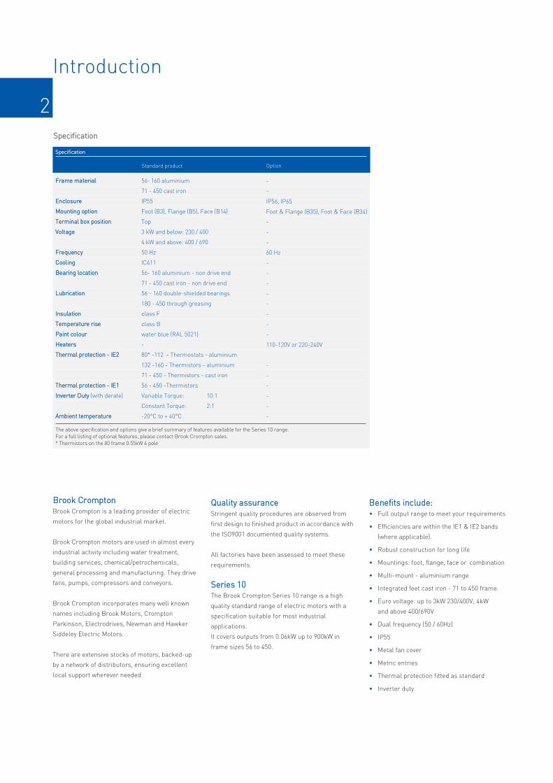
SSppeecciiffiiccaattiioonn
FFrraammee mmaatteerriiaall
EEnncclloossuurree
MMoouunnttiinngg ooppttiioonn
TTeerrmmiinnaall bbooxx ppoossiittiioonn
VVoollttaaggee
FFrreeqquueennccyy
CCoooolliinngg
BBeeaarriinngg llooccaattiioonn
LLuubbrriiccaattiioonn
IInnssuullaattiioonn
TTeemmppeerraattuurree rriissee
PPaaiinntt ccoolloouurr
HHeeaatteerrss
TThheerrmmaall pprrootteeccttiioonn -- IIEE22
TThheerrmmaall pprrootteeccttiioonn -- IIEE11
IInnvveerrtteerr DDuuttyy (with derate)
AAmmbbiieenntt tteemmppeerraattuurree
56-160 aluminium
71 - 450 cast iron
IP55
Foot (B3), Flange (B5), Face (B14)
Top
3 kW and below: 230 / 400
4 kW and above: 400 / 690
50 Hz
IC411
56- 160 aluminium - non drive end
71 - 450 cast iron - non drive end
56 - 160 double-shielded bearings
180 - 450 through greasing
class F
class B
water blue (RAL 5021)
-
80* -112 - Thermostats - aluminium
132 -160 - Thermistors - aluminium
71 - 450 - Thermistors - cast iron
56 - 450 -Thermistors
Variable Torque: 10:1
Constant Torque: 2:1
-20°C to + 40°C
-
-
IP56, IP65
Foot & Flange (B35), Foot & Face (B34)
-
-
-
60 Hz
-
-
-
-
-
-
-
-
110-120V or 220-240V
-
-
-
-
-
-
OptionStandard product
SSppeecciiffiiccaattiioonn
The above specification and options give a brief summary of features available for the Series 10 range.For a full listing of optional features, please contact Brook Crompton sales.* Thermistors on the 80 frame 0.55kW 4 pole
BBrrooookk CCrroommppttoonnBrook Crompton is a leading provider of electric
motors for the global industrial market.
Brook Crompton motors are used in almost every
industrial activity including water treatment,
building services, chemical/petrochemicals,
general processing and manufacturing. They drive
fans, pumps, compressors and conveyors.
Brook Crompton incorporates many well known
names including Brook Motors, Crompton
Parkinson, Electrodrives, Newman and Hawker
Siddeley Electric Motors.
There are extensive stocks of motors, backed-up
by a network of distributors, ensuring excellent
local support wherever needed.
QQuuaalliittyy aassssuurraanncceeStringent quality procedures are observed from
first design to finished product in accordance with
the ISO9001 documented quality systems.
All factories have been assessed to meet these
requirements.
SSeerriieess 1100The Brook Crompton Series 10 range is a high
quality standard range of electric motors with a
specification suitable for most industrial
applications.
It covers outputs from 0.06kW up to 900kW in
frame sizes 56 to 450.
BBeenneeffiittss iinncclluuddee::• Full output range to meet your requirements
• Efficiencies are within the IE1 & IE2 bands
(where applicable).
• Robust construction for long life
• Mountings: foot, flange, face or combination
• Multi-mount - aluminium range
• Integrated feet cast iron - 71 to 450 frame.
• Euro voltage: up to 3kW 230/400V; 4kW
and above 400/690V
• Dual frequency (50 / 60Hz)
• IP55
• Metal fan cover
• Metric entries
• Thermal protection fitted as standard
• Inverter duty

3
Standards and environment
DDiirreeccttiivveess
SSttaannddaarrddss
PPeerrffoorrmmaannccee IEC 60034-1
DDiimmeennssiioonnss IEC 60072-1
MMoouunnttiinngg IEC 60034-7
EEnncclloossuurree pprrootteeccttiioonn IEC 60034-5
VViibbrraattiioonn IEC 60034-14 (grade A)
NNooiissee IEC60034-9
SSttaannddaarrddss
RReeffeerreennccee nnuummbbeerrss
MMoottoorr CCEE mmaarrkkeedd
SSttaannddaarrddss
DDooccuummeennttaattiioonn ffoorr ccuussttoommeerrss’’ tteecchhnniiccaall ffiillee
SSaaffeettyy iinnssttrruuccttiioonnss wwiitthh eevveerryy mmoottoorr
CCoommmmeenntt
CCoommpplliiaannccee wwiitthh EEuurrooppeeaann ddiirreeccttiivveess aappppllyyiinngg ttoo AACC iinndduuccttiioonn mmoottoorrss
73/23/EEC
93/68/EEC
2006/95/EC
Yes
EN 60034
Declaration of conformity
Yes
Relevant electrical equip-
ment operating between
50 to 1000 volts AC
DDiirreeccttiivveess Low voltage(LV)
2006/42/EC
98/79/EC
98/37/EC
93/44/EEC
89/392/EEC
No
Not applicable
Certificate of incorporation
Yes
Statement(2)
Machinery(MD)
89/336/EEC
92/31/EEC
93/68/EEC
2004/108/EC
No
EN 60034-1
Statement(1)
Yes
Component
Electromagnetic compatibility(EMC)
(1) Motors operating from a correctly applied, sinusoidal (AC) supply meet the requirements of the EMC directive and are within the limits specified in standard EN 60034-1(2) When installed in accordance with our customer safety and installation and maintenance instructions, they can be put into service only when the machinery into which they
are being incorporated, has been declared to be in conformity with the machinery directive in accordance with Article 4(2) and Annex IIB of that Directive (98/37/EEC)
Series 10 motors are manufactured to theinternational standards listed below:
EEuurrooppeeaann ddiirreeccttiivveessThe following European directives apply:
EEnnvviirroonnmmeenntt EEnncclloossuurreeAll motors have degrees of IP protection as defined in IEC
EN 60034-5. The normal arrangement is IP55.
See Specification (page 2) for alternatives.
MMoottoorr ccoooolliinnggMotors are cooled in accordance with IEC 60034-6.
The normal arrangement is IC411 (Totally Enclosed Fan
Ventilated) via a fan mounted at the non-drive end.
MMiinniimmuumm EEnneerrggyy PPeerrffoorrmmaannccee SSttaannddaarrdd
TThhee nneeww ssttaannddaarrdd
The EU MEPS scheme sets new mmaannddaattoorryy
minimum efficiency levels for most single speed
3ph induction motors up to 375kW rated up to
1000V, unlike the narrow definition of the CEMEP
voluntary scheme which only covered a small
number of standard motors.
The Voluntary Agreement, since 1998, of CEMEP
for motor manufactures has expired
(classes EFF3 /EFF2/EFF1).
The new standard for motors is now mmaannddaattoorryy
regulation in Europe.
The scope of EU MEPS covers 2, 4 & 6 pole single
speed 3ph induction motors from 0.75 to 375kW,
rated up to 1000V based on continuous duty
operation.
Aiming to reduce energy consumption throughout
Europe and the rest of the world, it comes into ef-
fect in 3 stages . The effect of this is to maximise
potential savings in electric motor driven systems.
Base of the regulation is a new international IEC
60034-30 standard. It defines the following
efficiency classes :
IIEE11 - Standard Efficiency (comparable to EFF2)
IIEE22 - High Efficiency (comparable to EFF1 and USA
EPACT 60 Hz)
IIEE33 - Premium Efficiency (comparable to USA
“NEMA Premium” 60 Hz)
NNeeww EEffffiicciieennccyy lleevveellss iinn EEuurrooppee ((TTiimmee LLiinnee))
MMaannddaattoorryy ffrroomm::
Since 16th June 2011:
Minimum efficiency requirement at IE2 for all
motors covered 0.75 - 375kW
From 1st January 2015:
Minimum efficiency requirement at IE3 level for
7.5 - 375kW motors or IE2 level for motors
equipped with an appropriate variable speed drive.
From 1st January 2017:
Minimum efficiency requirement at IE3 level for
0.75 - 375kW motors or IE2 level for motors
equipped with an appropriate variable speed drive.
92/42/EEC
96/57/EC
2000/55/EC
2005/32/EC
Yes
EN 60034-30
Declaration of conformity
-
Minimum efficiency levels
for motor outputs
0.75 - 375kW
2-6 pole
Energy using products(EuP)

4
Performance data
3000 min-1 (2 pole), aluminium construction
0.09
0.12
0.18
0.25
0.37
0.55
0.75
1.1
1.5
2.2
3.0
4.0
5.5
7.5
11.0
15.0
18.5
2750
2750
2720
2720
2740
2740
2870
2870
2890
2890
2890
2900
2930
2930
2940
2940
2940
BB--DDAA5566MMAA
BB--DDAA5566MMBB
BB--DDAA6633MMAA
BB--DDAA6633MMBB
BB--DDAA7711MMAA
BB--DDAA7711MMBB
AA--DDAA8800MMAA
AA--DDAA8800MMBB
AA--DDAA9900SSAA
AA--DDAA9900LLAA
AA--DDAA110000LLAA
AA--DDAA111122MMAA
AA--DDAA113322SSAA
AA--DDAA113322SSBB
AA--DDAA116600MMAA
AA--DDAA116600MMBB
AA--DDAA116600LLAA
0.15
0.20
0.25
0.33
0.5
0.75
1.0
1.5
2.0
3.0
4.0
5.5
7.5
10
15
20
25
0.52
0.62
0.87
1.14
1.62
2.30
2.93
4.18
5.45
7.81
10.2
-
-
-
-
-
-
0.30
0.36
0.50
0.66
0.94
1.33
1.69
2.40
3.13
4.49
5.88
7.65
10.4
14.0
20.0
26.9
33.0
-
-
-
-
-
-
-
-
-
-
-
4.43
6.01
8.09
11.6
15.6
19.1
62.0
67.0
65.0
68.0
70.0
73.0
77.4
79.6
81.3
83.2
84.6
85.8
87.0
88.1
89.4
90.3
90.9
2.1
2.1
2.2
2.2
2.2
2.2
2.5
3.2
2.7
2.4
3.2
2.5
2.7
2.4
2.2
2.3
2.3
5.2
5.2
5.5
5.5
6.1
6.1
5.3
7.0
7.1
6.9
8.0
7.5
7.5
7.5
7.6
7.6
7.4
2.2
2.2
2.3
2.3
2.3
2.3
3.0
3.8
3.5
3.0
4.0
3.0
3.5
3.3
2.9
3.1
3.1
0.00018
0.00023
0.00031
0.0006
0.00075
0.0009
0.0012
0.0014
0.0029
0.0055
0.0109
0.0126
0.0377
0.0499
0.055
0.075
0.124
0.70
0.72
0.80
0.81
0.81
0.82
0.83
0.83
0.85
0.85
0.87
0.88
0.88
0.88
0.89
0.89
0.89
0.31
0.41
0.63
0.88
1.28
1.91
2.49
3.66
4.96
7.27
9.91
13.2
17.9
24.4
35.7
48.7
60.1
-
-
-
-
-
-
-
-
-
-
-
-
-
-
-
-
-
-
-
-
-
-
-
56
57
61
61
63
65
68
68
72
73
73
A-DA frame nomenclature indicates an IE2 efficiency motor
kW hp
PN
nmin–1
230 VA
400 VA
690 VA
h1.0 PN
MAMN
IAIN
MKMN
Jkgm2
IN
Rotor inertia WK2
Direct on line
pull out torque
Direct on line
starting current ratio
Direct on line
starting torque ratio
Power factor
Efficiency
Full load current at
rated voltage
Frame reference
and size
Full load speed in
revolutions per minute
Rated power
TypeCos Ø1.0 PN
Full load
torque
MNNm
MSMN
Direct on line
pull up torque
LPAdB(A)
Mean Sound pressure
level @ 1m on no load
kg
Weight
3.6
3.9
4.8
5.1
6.0
6.5
10.5
11.5
17.0
21.0
26.5
29.5
42.5
48.0
88.0
97.0
107
See performance data notes on page 28

5
Performance data
1500 min-1 (4 pole), aluminium construction
0.06
0.09
0.12
0.18
0.25
0.37
0.55
0.75
1.1
1.5
2.2
3.0
4.0
5.5
7.5
11.0
15.0
1325
1325
1310
1310
1330
1330
1390
1430
1430
1430
1440
1440
1450
1460
1460
1470
1470
BB--DDAA5566MMAA
BB--DDAA5566MMBB
BB--DDAA6633MMAA
BB--DDAA6633MMBB
BB--DDAA7711MMAA
BB--DDAA7711MMBB
BB--DDAA8800MMAA
AA--DDAA8800MMBB
AA--DDAA9900SSAA
AA--DDAA9900LLAA
AA--DDAA110000LLAA
AA--DDAA110000LLBB
AA--DDAA111122MMAA
AA--DDAA113322SSAA
AA--DDAA113322MMAA
AA--DDAA116600MMAA
AA--DDAA116600LLAA
0.08
0.12
0.16
0.25
0.33
0.50
0.75
1.0
1.5
2.0
3.0
4.0
5.5
7.5
10
15
20
0.46
0.64
0.73
1.02
1.30
1.85
2.59
3.15
4.41
5.76
8.09
10.7
-
-
-
-
-
0.27
0.37
0.42
0.59
0.75
1.06
1.49
1.81
2.53
3.31
4.65
6.18
8.13
10.9
14.5
21.0
28.4
-
-
-
-
-
-
-
-
-
-
-
-
4.71
6.32
8.42
12.2
16.5
56.0
58.0
57.0
60.0
65.0
67.0
71.1
79.6
81.4
82.8
84.3
85.5
86.6
87.7
88.7
89.8
90.6
2.0
2.0
2.1
2.1
2.1
2.1
2.3
2.4
3.0
3.2
3.0
2.6
3.5
2.2
2.4
2.5
2.5
4.0
4.0
4.4
4.4
5.2
5.2
5.2
5.0
6.0
6.8
7.0
7.0
7.5
6.4
7.0
6.9
7.5
2.1
2.1
2.2
2.2
2.2
2.2
2.3
2.9
3.5
3.8
3.5
3.3
4.0
2.8
3.0
2.9
3.0
0.0003
0.0004
0.0005
0.0006
0.0008
0.0013
0.0018
0.0021
0.0023
0.0027
0.0054
0.0067
0.0095
0.0214
0.0296
0.0747
0.0918
0.58
0.61
0.72
0.73
0.74
0.75
0.75
0.75
0.77
0.79
0.81
0.82
0.82
0.83
0.84
0.84
0.84
0.43
0.65
0.84
1.26
1.73
2.65
3.78
5.0
7.3
10.0
14.6
19.9
26.3
36.0
49.0
71.5
97.4
-
-
-
-
-
-
-
-
-
-
-
-
-
-
-
-
-
-
-
-
-
-
-
-
46
48
48
52
52
53
59
59
62
62
A-DA frame nomenclature indicates an IE2 efficiency motor
kW hp
PN
nmin–1
230 VA
400 VA
690 VA
h1.0 PN
MAMN
IAIN
MKMN
Jkgm2
IN
Rotor inertia WK2
Direct on line
pull out torque
Direct on line
starting current ratio
Direct on line
starting torque ratio
Power factor
Efficiency
Full load current at
rated voltage
Frame reference
and size
Full load speed in
revolutions per minute
Rated power
TypeCos Ø1.0 PN
Full load
torque
MNNm
MSMN
Direct on line
pull up torque
LPAdB(A)
Mean Sound pressure
level @ 1m on no load
kg
Weight
3.6
3.9
4.8
5.1
6.0
6.3
12.5
14.0
18.0
20.5
29.0
34.0
38.0
48.0
58.5
90.0
104
See performance data notes on page 28
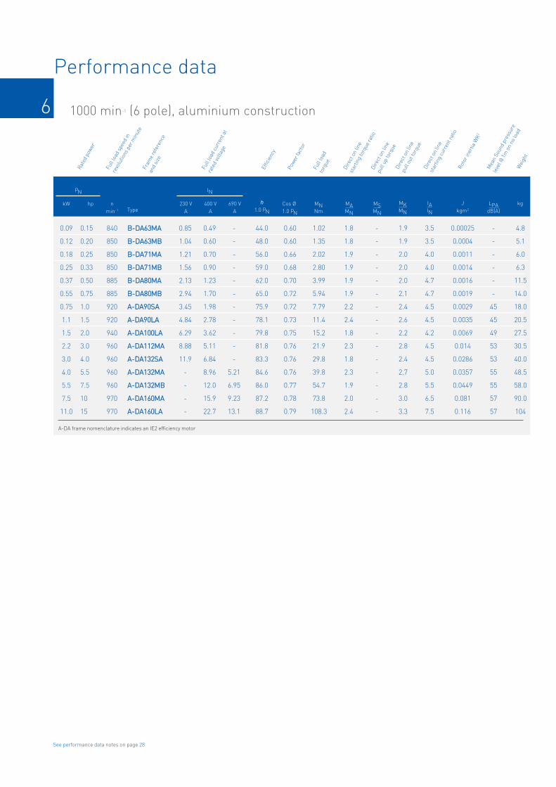
6
Performance data
1000 min-1 (6 pole), aluminium construction
0.09
0.12
0.18
0.25
0.37
0.55
0.75
1.1
1.5
2.2
3.0
4.0
5.5
7.5
11.0
840
850
850
850
885
885
920
920
940
960
960
960
960
970
970
BB--DDAA6633MMAA
BB--DDAA6633MMBB
BB--DDAA7711MMAA
BB--DDAA7711MMBB
BB--DDAA8800MMAA
BB--DDAA8800MMBB
AA--DDAA9900SSAA
AA--DDAA9900LLAA
AA--DDAA110000LLAA
AA--DDAA111122MMAA
AA--DDAA113322SSAA
AA--DDAA113322MMAA
AA--DDAA113322MMBB
AA--DDAA116600MMAA
AA--DDAA116600LLAA
0.15
0.20
0.25
0.33
0.50
0.75
1.0
1.5
2.0
3.0
4.0
5.5
7.5
10
15
0.85
1.04
1.21
1.56
2.13
2.94
3.45
4.84
6.29
8.88
11.9
-
-
-
-
0.49
0.60
0.70
0.90
1.23
1.70
1.98
2.78
3.62
5.11
6.84
8.96
12.0
15.9
22.7
-
-
-
-
-
-
-
-
-
-
-
5.21
6.95
9.23
13.1
44.0
48.0
56.0
59.0
62.0
65.0
75.9
78.1
79.8
81.8
83.3
84.6
86.0
87.2
88.7
1.8
1.8
1.9
1.9
1.9
1.9
2.2
2.4
1.8
2.3
1.8
2.3
1.9
2.0
2.4
3.5
3.5
4.0
4.0
4.7
4.7
4.5
4.5
4.2
4.5
4.5
5.0
5.5
6.5
7.5
1.9
1.9
2.0
2.0
2.0
2.1
2.4
2.6
2.2
2.8
2.4
2.7
2.8
3.0
3.3
0.00025
0.0004
0.0011
0.0014
0.0016
0.0019
0.0029
0.0035
0.0069
0.014
0.0286
0.0357
0.0449
0.081
0.116
0.60
0.60
0.66
0.68
0.70
0.72
0.72
0.73
0.75
0.76
0.76
0.76
0.77
0.78
0.79
1.02
1.35
2.02
2.80
3.99
5.94
7.79
11.4
15.2
21.9
29.8
39.8
54.7
73.8
108.3
-
-
-
-
-
-
-
-
-
-
-
-
-
-
-
-
-
-
-
-
-
45
45
49
53
53
55
55
57
57
A-DA frame nomenclature indicates an IE2 efficiency motor
kW hp
PN
nmin–1
230 VA
400 VA
690 VA
h1.0 PN
MAMN
IAIN
MKMN
Jkgm2
IN
Rotor inertia WK2
Direct on line
pull out torque
Direct on line
starting current ratio
Direct on line
starting torque ratio
Power factor
Efficiency
Full load current at
rated voltage
Frame reference
and size
Full load speed in
revolutions per minute
Rated power
TypeCos Ø1.0 PN
Full load
torque
MNNm
MSMN
Direct on line
pull up torque
LPAdB(A)
Mean Sound pressure
level @ 1m on no load
kg
Weight
4.8
5.1
6.0
6.3
11.5
14.0
18.0
20.5
27.5
30.5
40.0
48.5
58.0
90.0
104
See performance data notes on page 28
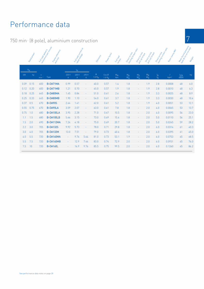
7
Performance data
750 min-1 (8 pole), aluminium construction
0.09
0.12
0.18
0.25
0.37
0.55
0.75
1.1
1.5
2.2
3.0
4.0
5.5
7.5
600
600
645
645
670
670
680
680
690
705
705
720
720
720
BB--DDAA7711MMAA
BB--DDAA7711MMBB
BB--DDAA8800MMAA
BB--DDAA8800MMBB
BB--DDAA9900SS
BB--DDAA9900LLAA
BB--DDAA110000LLAA
BB--DDAA110000LLBB
BB--DDAA111122MMAA
BB--DDAA113322SS
BB--DDAA113322MM
BB--DDAA116600MMAA
BB--DDAA116600MMBB
BB--DDAA116600LL
0.15
0.20
0.25
0.33
0.5
0.75
1.0
1.5
2.0
3.0
4.0
5.5
7.5
10
0.99
1.21
1.45
1.90
2.44
3.59
3.95
5.46
7.24
9.92
13.0
-
-
-
0.57
0.70
0.84
1.10
1.41
2.07
2.28
3.15
4.18
5.73
7.51
9.76
12.9
16.9
-
-
-
-
-
-
-
-
-
-
-
5.64
7.44
9.76
40.0
45.0
51.0
54.0
62.0
63.0
71.0
73.0
75.0
78.0
79.0
81.0
83.0
85.5
1.8
1.8
1.8
1.8
1.8
1.8
1.8
1.8
1.8
1.8
1.8
1.9
2.0
2.0
2.8
2.8
3.3
3.3
4.0
4.0
4.0
5.0
5.0
6.0
6.0
6.0
6.0
6.0
1.9
1.9
1.9
1.9
1.9
2.0
2.0
2.0
2.0
2.0
2.0
2.0
2.0
2.0
0.0008
0.0010
0.0025
0.0030
0.0051
0.0065
0.0095
0.0110
0.0245
0.0314
0.0395
0.0753
0.0931
0.1260
0.57
0.57
0.61
0.61
0.61
0.61
0.67
0.69
0.69
0.71
0.73
0.73
0.74
0.75
1.4
1.9
2.6
3.7
5.2
7.8
10.5
15.4
20.7
29.8
40.6
53.1
72.9
99.5
-
-
-
-
-
-
-
-
-
-
-
-
-
-
48
48
48
48
53
53
56
56
59
61
61
65
65
65
IIEE11
kW hp
PN
nmin–1
230 VA
400 VA
690 VA
h1.0 PN
MAMN
IAIN
MKMN
Jkgm2
IN
Rotor inertia WK2
Direct on line
pull out torque
Direct on line
starting current ratio
Direct on line
starting torque ratio
Power factor
Efficiency
Full load current at
rated voltage
Frame reference
and size
Full load speed in
revolutions per minute
Rated power
TypeCos Ø1.0 PN
Full load
torque
MNNm
MSMN
Direct on line
pull up torque
LPAdB(A)
Mean Sound pressure
level @ 1m on no load
kg
Weight
6.0
6.3
8.9
10.4
12.1
13.7
23.0
25.1
28.2
40.3
45.0
68.5
76.0
86.2
See performance data notes on page 28
8
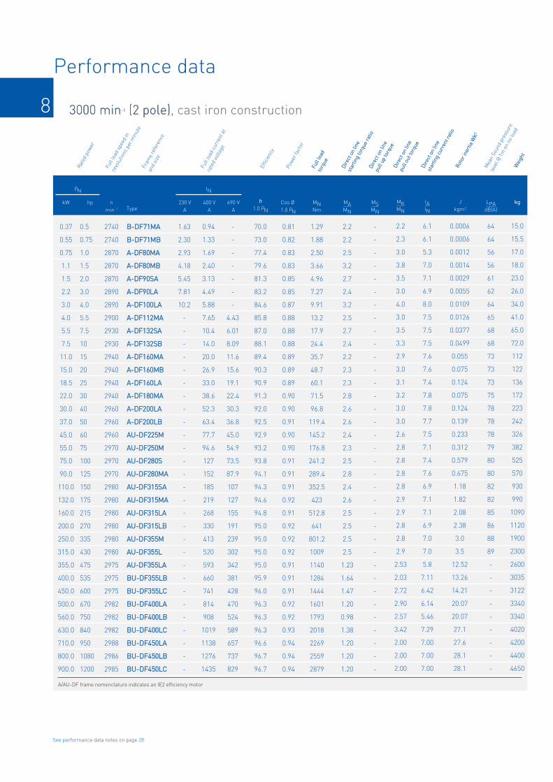
Performance data
3000 min-1 (2 pole)3000 min-1 (2 pole), cast iron construction
0.37
0.55
0.75
1.1
1.5
2.2
3.0
4.0
5.5
7.5
11.0
15.0
18.5
22.0
30.0
37.0
45.0
55.0
75.0
90.0
110.0
132.0
160.0
200.0
250.0
315.0
355.0
400.0
450.0
500.0
560.0
630.0
710.0
800.0
900.0
2740
2740
2870
2870
2870
2890
2890
2900
2930
2930
2940
2940
2940
2940
2960
2960
2960
2970
2970
2970
2980
2980
2980
2980
2980
2980
2975
2975
2975
2982
2982
2982
2988
2986
2985
BB--DDFF7711MMAA
BB--DDFF7711MMBB
AA--DDFF8800MMAA
AA--DDFF8800MMBB
AA--DDFF9900SSAA
AA--DDFF9900LLAA
AA--DDFF110000LLAA
AA--DDFF111122MMAA
AA--DDFF113322SSAA
AA--DDFF113322SSBB
AA--DDFF116600MMAA
AA--DDFF116600MMBB
AA--DDFF116600LLAA
AA--DDFF118800MMAA
AA--DDFF220000LLAA
AA--DDFF220000LLBB
AAUU--DDFF222255MM
AAUU--DDFF225500MM
AAUU--DDFF228800SS
AAUU--DDFF228800MMAA
AAUU--DDFF331155SSAA
AAUU--DDFF331155MMAA
AAUU--DDFF331155LLAA
AAUU--DDFF331155LLBB
AAUU--DDFF335555MM
AAUU--DDFF335555LL
AAUU--DDFF335555LLAA
BBUU--DDFF335555LLBB
BBUU--DDFF335555LLCC
BBUU--DDFF440000LLAA
BBUU--DDFF440000LLBB
BBUU--DDFF440000LLCC
BBUU--DDFF445500LLAA
BBUU--DDFF445500LLBB
BBUU--DDFF445500LLCC
0.5
0.75
1.0
1.5
2.0
3.0
4.0
5.5
7.5
10
15
20
25
30
40
50
60
75
100
125
150
175
215
270
335
430
475
535
600
670
750
840
950
1080
1200
MAMN
IAIN
MKMN
Jkgm2
1.63
2.30
2.93
4.18
5.45
7.81
10.2
-
-
-
-
-
-
-
-
-
-
-
-
-
-
-
-
-
-
-
-
-
-
-
-
-
-
-
-
0.94
1.33
1.69
2.40
3.13
4.49
5.88
7.65
10.4
14.0
20.0
26.9
33.0
38.6
52.3
63.4
77.7
94.6
127
152
185
219
268
330
413
520
593
660
741
814
908
1019
1138
1276
1435
-
-
-
-
-
-
-
4.43
6.01
8.09
11.6
15.6
19.1
22.4
30.3
36.8
45.0
54.9
73.5
87.9
107
127
155
191
239
302
342
381
428
470
524
589
657
737
829
70.0
73.0
77.4
79.6
81.3
83.2
84.6
85.8
87.0
88.1
89.4
90.3
90.9
91.3
92.0
92.5
92.9
93.2
93.8
94.1
94.3
94.6
94.8
95.0
95.0
95.0
95.0
95.9
96.0
96.3
96.3
96.3
96.6
96.7
96.7
2.2
2.2
2.5
3.2
2.7
2.4
3.2
2.5
2.7
2.4
2.2
2.3
2.3
2.8
2.6
2.6
2.4
2.3
2.5
2.8
2.4
2.6
2.5
2.5
2.5
2.5
1.23
1.64
1.47
1.20
0.98
1.38
1.20
1.20
1.20
6.1
6.1
5.3
7.0
7.1
6.9
8.0
7.5
7.5
7.5
7.6
7.6
7.4
7.8
7.8
7.7
7.5
7.1
7.4
7.6
6.9
7.1
7.1
6.9
7.0
7.0
5.8
7.11
6.42
6.14
5.46
7.29
7.00
7.00
7.00
2.2
2.3
3.0
3.8
3.5
3.0
4.0
3.0
3.5
3.3
2.9
3.0
3.1
3.2
3.0
3.0
2.6
2.8
2.8
2.8
2.8
2.9
2.9
2.8
2.8
2.9
2.53
2.03
2.72
2.90
2.57
3.42
2.00
2.00
2.00
0.0006
0.0006
0.0012
0.0014
0.0029
0.0055
0.0109
0.0126
0.0377
0.0499
0.055
0.075
0.124
0.075
0.124
0.139
0.233
0.312
0.579
0.675
1.18
1.82
2.08
2.38
3.0
3.5
12.52
13.26
14.21
20.07
20.07
27.1
27.6
28.1
28.1
Rotor inertia WK2
Direct on line
pull out torque
Direct on line
starting current ratio
Direct on line
starting torque ratio
0.81
0.82
0.83
0.83
0.85
0.85
0.87
0.88
0.88
0.88
0.89
0.89
0.89
0.90
0.90
0.91
0.90
0.90
0.91
0.91
0.91
0.92
0.91
0.92
0.92
0.92
0.91
0.91
0.91
0.92
0.92
0.93
0.94
0.94
0.94
1.29
1.88
2.50
3.66
4.96
7.27
9.91
13.2
17.9
24.4
35.7
48.7
60.1
71.5
96.8
119.4
145.2
176.8
241.2
289.4
352.5
423
512.8
641
801.2
1009
1140
1284
1444
1601
1793
2018
2269
2559
2879
Full load
torque
MNNm
MSMN
-
-
-
-
-
-
-
-
-
-
-
-
-
-
-
-
-
-
-
-
-
-
-
-
-
-
-
-
-
-
-
-
-
-
-
Direct on line
pull up torque
LPAdB(A)
64
64
56
56
61
62
64
65
68
68
73
73
73
75
78
78
78
79
80
80
82
82
85
86
88
89
-
-
-
-
-
-
-
-
-
Mean Sound pressure
level @ 1m on no load
A/AU-DF frame nomenclature indicates an IE2 efficiency motor
kW hp
PN
nmin–1
230 VA
400 VA
690 VA
h1.0 PN
MAMN
IAIN
MKMN
Jkgm2
IN
Rotor inertia WK2
Direct on line
pull out torque
Direct on line
starting current ratio
Direct on line
starting torque ratio
Power factor
Efficiency
Full load current at
rated voltage
Frame reference
and size
Full load speed in
revolutions per minute
Rated power
TypeCos Ø1.0 PN
Full load
torque
MNNm
MSMN
Direct on line
pull up torque
LPAdB(A)
kg
Weight
kg
15.0
15.5
17.0
18.0
23.0
26.0
34.0
41.0
65.0
72.0
112
122
136
172
223
242
326
382
525
570
930
990
1090
1120
1900
2300
2600
3035
3122
3340
3340
4020
4200
4400
4650
Weight
See performance data notes on page 28

9
Performance data
1500 min-1 (4 pole), cast iron construction
0.25
0.37
0.55
0.75
1.1
1.5
2.2
3.0
4.0
5.5
7.5
11.0
15.0
18.5
22.0
30.0
37.0
45.0
55.0
75.0
90.0
110.0
132.0
160.0
200.0
250.0
315.0
355.0
400.0
450.0
500.0
560.0
630.0
710.0
800.0
900.0
1330
1330
1390
1430
1430
1430
1440
1440
1410
1460
1460
1470
1470
1470
1470
1470
1480
1475
1475
1480
1480
1485
1485
1485
1485
1485
1490
1485
1485
1485
1492
1492
1492
1492
1492
1492
BB--DDFF7711MMAA
BB--DDFF7711MMBB
BB--DDFF8800MMAA
AA--DDFF8800MMBB
AA--DDFF9900SSAA
AA--DDFF9900LLAA
AA--DDFF110000LLAA
AA--DDFF110000LLBB
AA--DDFF111122MMAA
AA--DDFF113322SSAA
AA--DDFF113322MMAA
AA--DDFF116600MMAA
AA--DDFF116600LLAA
AA--DDFF118800MMAA
AA--DDFF118800LLAA
AA--DDFF220000LL
AA--DDFF225555SS
AAUU--DDFF222255MM
AAUU--DDFF225500MMAA
AAUU--DDFF228800SS
AAUU--DDFF228800MMAA
AAUU--DDFF331155SS
AAUU--DDFF331155MM
AAUU--DDFF331155LLAA
AAUU--DDFF331155LLBB
AAUU--DDFF335555MM
AAUU--DDFF335555LL
AAUU--DDFF335555LLAA
BBUU--DDFF335555LLBB
BBUU--DDFF335555LLCC
BBUU--DDFF440000LLAA
BBUU--DDFF440000LLBB
BBUU--DDFF440000LLCC
BBUU--DDFF445500LLAA
BBUU--DDFF445500LLBB
BBUU--DDFF445500LLCC
0.33
0.50
0.75
1.0
1.5
2.0
3.0
4.0
5.5
7.5
10
15
20
25
30
40
50
60
75
100
125
150
175
215
270
335
430
475
535
600
670
750
840
950
1070
1200
1.30
1.83
2.58
3.15
4.41
5.76
8.09
10.7
13.3
-
-
-
-
-
-
-
-
-
-
-
-
-
-
-
-
-
-
-
-
-
-
-
-
-
-
-
0.75
1.06
1.49
1.81
2.53
3.31
4.65
6.18
8.13
10.9
14.5
21.0
28.4
34.0
39.8
53.9
66.2
80.2
97.6
132
159
189
226
273
341
422
531
612
680
757
831
924
1043
1164
1308
1496
-
-
-
-
-
-
-
-
4.71
6.32
8.42
12.2
16.5
19.7
23.1
31.3
38.4
46.5
56.6
76.7
91.9
109
131
159
198
244
308
353
393
437
480
533
602
672
755
864
65.0
67.0
71.1
79.6
81.4
82.8
84.3
85.5
86.6
87.7
88.7
89.8
90.6
91.2
91.6
92.3
92.7
93.1
93.5
94.0
94.2
94.5
94.7
94.9
95.1
95.1
95.1
95.1
96.4
96.4
96.4
96.4
96.4
96.4
96.6
96.6
2.1
2.1
2.2
2.4
3.0
3.2
3.0
2.6
3.5
2.2
2.4
2.5
2.5
2.6
2.6
2.4
2.5
2.5
2.6
2.7
2.7
2.7
2.7
3.0
3.0
2.8
2.6
1.93
1.80
1.80
1.83
2.02
1.75
1.30
1.53
1.75
5.2
5.2
5.2
5.0
6.0
6.8
7.0
7.0
7.5
6.4
7.0
6.9
7.5
7.8
7.5
7.1
7.5
7.6
7.3
7.6
7.5
7.1
7.3
7.4
7.6
7.5
7.4
6.5
6.5
6.5
6.19
6.64
5.81
6.17
6.91
5.81
2.2
2.2
2.3
2.9
3.5
3.8
3.5
3.3
4.0
2.8
3.0
2.9
3.0
3.1
3.1
2.9
2.7
2.8
2.7
2.7
2.7
2.9
2.9
3.0
3.0
2.9
2.8
2.6
2.6
2.6
2.52
2.67
2.34
2.57
2.28
2.34
0.0006
0.0008
0.0018
0.0021
0.0023
0.0027
0.0054
0.0067
0.0095
0.0214
0.0296
0.0747
0.0918
0.139
0.158
0.262
0.406
0.469
0.66
1.12
1.46
3.11
3.62
4.13
4.73
6.5
8.2
9.5
10.6
11.5
18.41
19.62
21.33
41.00
49.50
49.50
0.74
0.75
0.75
0.75
0.77
0.79
0.81
0.82
0.82
0.83
0.84
0.84
0.84
0.86
0.87
0.87
0.87
0.87
0.87
0.87
0.87
0.89
0.89
0.89
0.89
0.90
0.90
0.88
0.88
0.89
0.90
0.90
0.91
0.91
0.93
0.92
1.80
2.66
3.78
5.01
7.35
10.0
14.6
19.9
26.3
40.0
49.0
71.4
97.4
120.2
143
195
239
290.4
356
484
581
707
849
1029
1286
1608
2026
2283
2572
2894
3200
3585
4033
4545
5120
5760
-
-
-
-
-
-
-
-
-
-
-
-
-
-
-
-
-
-
-
-
-
-
-
-
-
-
-
-
-
-
-
-
-
-
-
-
55
55
58
46
48
48
52
52
53
59
59
62
62
64
64
64
64
65
66
69
69
77
77
82
82
84
84
-
-
-
-
-
-
-
-
-
A/AU-DF frame nomenclature indicates an IE2 efficiency motor
kW hp
PN
nmin–1
230 VA
400 VA
690 VA
h1.0 PN
MAMN
IAIN
MKMN
Jkgm2
IN
Rotor inertia WK2
Direct on line
pull out torque
Direct on line
starting current ratio
Direct on line
starting torque ratio
Power factor
Efficiency
Full load current at
rated voltage
Frame reference
and size
Full load speed in
revolutions per minute
Rated power
TypeCos Ø1.0 PN
Full load
torque
MNNm
MSMN
Direct on line
pull up torque
LPAdB(A)
Mean Sound pressure
level @ 1m on no load
kg
Weight
14.0
14.5
15.0
16.0
23.0
25.0
33.0
35.0
42.0
65.0
76.0
118
132
164
182
245
258
290
388
510
606
910
1000
1055
1128
1700
1900
2150
2300
2460
3132
3548
3589
4055
4724
4732
See performance data notes on page 28

10
Performance data
1000 min-1 (6 pole), cast iron construction
0.18
0.25
0.37
0.55
0.75
1.1
1.5
2.2
3.0
4.0
5.5
7.5
11.0
15.0
18.5
22.0
30.0
37.0
45.0
55.0
75.0
90.0
110.0
132.0
160.0
200.0
250.0
315.0
355.0
400.0
450.0
500.0
560.0
630.0
710.0
800.0
850
850
885
885
920
920
940
960
960
960
960
970
970
970
970
970
980
985
980
980
990
990
990
990
990
990
990
990
990
990
994
994
994
994
994
994
BB--DDFF7711MMAA
BB--DDFF7711MMBB
BB--DDFF8800MMAA
BB--DDFF8800MMBB
AA--DDFF9900SSAA
AA--DDFF9900LLAA
AA--DDFF110000LLAA
AA--DDFF111122MMAA
AA--DDFF113322SSAA
AA--DDFF113322MMAA
AA--DDFF113322MMBB
AA--DDFF116600MMAA
AA--DDFF116600LLAA
AA--DDFF118800LLAA
AA--DDFF220000LLAA
AA--DDFF220000LLBB
AAUU--DDFF222255MM
AAUU--DDFF225500MM
AAUU--DDFF228800SS
AAUU--DDFF228800MMAA
AAUU--DDFF331155SSAA
AAUU--DDFF331155MMAA
AAUU--DDFF331155LLAA
AAUU--DDFF331155LLBB
AAUU--DDFF335555MMAA
AAUU--DDFF335555MMBB
AAUU--DDFF335555LL
AAUU--DDAA335555LLAA
AAUU--DDFF335555LLBB
BBUU--DDFF440000LLAA
BBUU--DDFF440000LLBB
BBUU--DDFF440000LLCC
BBUU--DDFF445500MMBB
BBUU--DDFF445500LLAA
BBUU--DDFF445500LLBB
BBUU--DDFF445500LLCC
0.25
0.33
0.5
0.75
1.0
1.5
2.0
3.0
4.0
5.5
7.5
10
15
20
25
30
40
50
60
75
100
125
150
175
215
270
335
420
480
544
612
680
760
850
960
1080
1.21
1.56
2.13
2.94
3.45
4.84
6.29
8.88
11.9
-
-
-
-
-
-
-
-
-
-
-
-
-
-
-
-
-
-
-
-
-
-
-
-
-
-
-
0.70
0.90
1.23
1.70
1.98
2.78
3.62
5.11
6.84
8.98
12.0
15.9
22.7
29.4
36.5
43.1
56.2
68.1
81.5
99.2
134
161
196
231
277
345
432
563
634
701
783
871
874
1097
1235
1381
-
-
-
-
-
-
-
-
-
5.21
6.95
9.23
13.1
17.1
21.1
25.0
32.6
39.5
47.2
57.5
77.9
93.2
113
133
160
200
249
325
366
405
452
503
505
633
713
797
56.0
59.0
62.0
65.0
75.9
78.1
79.8
81.8
83.3
84.6
86.0
87.2
88.7
89.7
90.4
90.9
91.7
92.2
92.7
93.1
93.7
94.0
94.3
94.6
94.8
95.0
95.0
95.0
95.0
95.9
95.9
96.1
96.0
96.1
95.9
96.5
1.9
1.9
1.9
1.9
2.2
2.4
1.8
2.3
1.8
2.3
1.9
2.0
2.4
2.0
2.3
2.3
2.2
2.5
2.2
2.4
2.8
2.7
2.9
3.0
3.1
3.0
3.1
2.1
2.1
2.08
2.07
1.86
1.64
1.65
1.71
1.52
4.4
4.0
4.7
4.7
4.5
4.5
4.2
4.5
4.5
5.0
5.5
6.5
7.5
6.4
7.0
7.0
6.5
6.9
7.0
7.1
7.3
7.1
7.4
7.6
7.6
7.8
7.7
6.5
6.5
6.38
6.31
5.72
5.99
5.99
6.13
5.47
2.0
2.0
2.0
2.1
2.4
2.6
2.2
2.8
2.4
2.7
2.8
3.0
3.3
2.7
3.0
2.8
2.7
2.7
2.4
2.5
3.0
2.9
2.9
3.1
3.1
3.0
3.0
2.4
2.4
2.48
2.43
2.19
2.32
2.30
2.33
2.06
0.0011
0.0014
0.0016
0.0019
0.0029
0.0035
0.0069
0.014
0.0286
0.0357
0.0449
0.081
0.116
0.207
0.315
0.36
0.547
0.843
1.39
1.65
4.11
4.78
5.45
6.12
9.5
10.4
12.4
13.5
14.3
21.86
22.31
23.52
54.10
60.60
67.90
67.90
0.66
0.68
0.70
0.72
0.72
0.73
0.75
0.76
0.76
0.76
0.77
0.78
0.79
0.82
0.81
0.81
0.84
0.85
0.86
0.86
0.86
0.86
0.86
0.87
0.88
0.88
0.88
0.85
0.85
0.86
0.86
0.86
0.86
0.86
0.86
0.87
2.02
2.81
3.99
5.94
7.79
11.4
15.2
21.9
29.8
39.8
54.7
73.8
108.3
147.7
182.1
216.6
292.3
358.7
438.5
536
723
868
1061
1273
1543
1929
2412
3039
3424
3856
4323
4804
5380
6052
6821
7686
-
-
-
-
-
-
-
-
-
-
-
-
-
-
-
-
-
-
-
-
-
-
-
-
-
-
-
-
-
-
-
-
-
-
-
-
52
52
54
54
45
45
49
53
53
55
55
57
57
58
58
61
62
62
63
64
68
68
73
73
80
80
80
-
-
-
-
-
-
-
-
-
A/AU-DF frame nomenclature indicates an IE2 efficiency motor
kW hp
PN
nmin–1
230 VA
400 VA
690 VA
h1.0 PN
MAMN
IAIN
MKMN
Jkgm2
IN
Rotor inertia WK2
Direct on line
pull out torque
Direct on line
starting current ratio
Direct on line
starting torque ratio
Power factor
Efficiency
Full load current at
rated voltage
Frame reference
and size
Full load speed in
revolutions per minute
Rated power
TypeCos Ø1.0 PN
Full load
torque
MNNm
MSMN
Direct on line
pull up torque
LPAdB(A)
Mean Sound pressure
level @ 1m on no load
kg
Weight
14.0
14.5
15.0
16.0
19.0
22.0
32.0
41.0
44.0
53.0
63.5
118
145
198
200
228
265
370
490
540
900
980
1045
1100
1550
1600
1700
2310
2490
3560
3840
3870
4200
4620
5080
5080
See performance data notes on page 28

11
Performance data notes
750 min-1 (8 pole), cast iron construction
0.09
0.12
0.18
0.25
0.37
0.55
0.75
1.1
1.5
2.2
3.0
4.0
5.5
7.5
11.0
15.0
18.5
22.0
30.0
37.0
45.0
55.0
75.0
90.0
110.0
132.0
160.0
200.0
250.0
315.0
355.0
400.0
450.0
500.0
600
600
645
645
670
670
680
680
690
705
705
720
720
720
730
730
730
730
735
735
735
735
735
735
735
740
740
740
740
740
745
745
745
745
BB--DDFF7711MMAA
BB--DDFF7711MMBB
BB--DDFF8800MMAA
BB--DDFF8800MMBB
BB--DDFF9900SS
BB--DDFF9900LLAA
BB--DDFF110000LLAA
BB--DDFF110000LLBB
BB--DDFF111122MMAA
BB--DDFF113322SS
BB--DDFF113322MM
BB--DDFF116600MMAA
BB--DDFF116600MMBB
BB--DDFF116600LL
BB--DDFF118800LL
BB--DDFF220000LL
BBUU--DDFF222255SS
BBUU--DDFF222255MM
BBUU--DDFF225500MM
BBUU--DDFF228800SS
BBUU--DDFF228800MM
BBUU--DDFF331155SSAA
BBUU--DDFF331155MMAA
BBUU--DDFF331155LLAA
BBUU--DDFF331155LLBB
BBUU--DDFF335555MMAA
BBUU--DDFF335555MMBB
BBUU--DDFF335555LL
BBUU--DDFF335555LLBB
BBUU--DDFF335555LLCC
BBUU--DDFF440000LLBB
BBUU--DDFF440000LLCC
BBUU--DDFF445500LLBB
BBUU--DDFF445500LLCC
0.15
0.20
0.25
0.33
0.5
0.75
1.0
1.5
2.0
3.0
4.0
5.5
7.5
10
15
20
25
30
40
50
60
75
100
125
150
175
215
270
340
420
480
540
600
675
0.99
1.21
1.45
1.90
2.44
3.58
3.95
5.45
7.24
9.92
13.0
-
-
-
-
-
-
-
-
-
-
-
-
-
-
-
-
-
-
-
-
-
-
-
0.57
0.70
0.84
1.10
1.41
2.07
2.28
3.15
4.18
5.73
7.51
9.76
12.9
16.9
23.9
32.4
39.0
45.0
60.2
73.9
89.4
106
144
169
206
248
299
368
485
610
641
723
817
913
-
-
-
-
-
-
-
-
-
-
-
5.64
7.44
9.76
13.8
18.7
22.5
26.0
34.8
42.7
51.6
61.2
83.1
97.6
119
143
172
212
280
352
370
417
472
527
40.0
45.0
51.0
54.0
62.0
63.0
71.0
73.0
75.0
78.0
79.0
81.0
83.0
85.5
87.5
88.0
90.0
90.5
91.0
91.5
92.0
92.8
93.0
93.8
94.0
93.7
94.2
94.5
95.3
95.5
95.6
95.6
95.7
95.7
1.8
1.8
1.8
1.8
1.8
1.8
1.8
1.8
1.8
1.8
1.8
1.9
2.0
2.0
2.0
2.0
1.9
1.9
1.9
1.9
1.8
1.8
1.8
1.8
1.8
1.8
1.8
1.8
1.80
1.80
1.72
1.96
1.62
1.74
2.8
2.8
3.3
3.3
4.9
4.0
4.0
5.0
5.0
6.0
6.0
6.0
6.0
6.0
6.0
6.6
6.6
6.6
6.6
6.6
6.6
6.6
6.6
6.6
6.4
6.4
6.4
6.4
6.5
6.5
5.84
6.39
5.43
5.65
1.9
1.9
1.9
1.9
1.9
2.0
2.0
2.0
2.0
2.0
2.0
2.0
2.0
2.0
2.0
2.0
2.0
2.0
2.0
2.0
2.0
2.0
2.0
2.0
2.0
2.0
2.0
2.0
2.0
2.0
2.25
2.44
2.18
2.23
0.0008
0.0010
0.0025
0.0030
0.0051
0.0065
0.0095
0.0110
0.0245
0.0314
0.0395
0.0753
0.0931
0.1260
0.203
0.399
0.491
0.547
0.834
1.93
3.65
4.79
5.58
6.37
7.23
7.9
10.3
12.3
14.53
15.39
29.76
31.34
75.20
79.30
0.57
0.57
0.61
0.61
0.61
0.61
0.67
0.69
0.69
0.71
0.73
0.73
0.74
0.75
0.76
0.76
0.76
0.78
0.79
0.79
0.79
0.81
0.81
0.82
0.82
0.82
0.82
0.83
0.78
0.78
0.85
0.85
0.83
0.83
1.3
2.16
2.66
3.70
5.27
7.84
10.5
15.4
20.8
29.8
40.6
53.1
72.9
99.5
144
196
242
288
390
481
585
715
975
1169
1429
1704
2065
2581
3226
4065
4551
5128
5768
6409
-
-
-
-
-
-
-
-
-
-
-
-
-
-
-
-
-
-
-
-
-
-
-
-
-
-
-
-
-
-
-
-
-
-
48
48
48
48
53
53
56
56
59
61
61
65
65
65
70
73
73
73
75
76
76
82
82
82
82
90
90
90
-
-
-
-
-
-
kW hp
PN
nmin–1
230 VA
400 VA
690 VA
h1.0 PN
MAMN
IAIN
MKMN
Jkgm2
IN
Rotor inertia WK2
Direct on line
pull out torque
Direct on line
starting current ratio
Direct on line
starting torque ratio
Power factor
Efficiency
Full load current at
rated voltage
Frame reference
and size
Full load speed in
revolutions per minute
Rated power
TypeCos Ø1.0 PN
Full load
torque
MNNm
MSMN
Direct on line
pull up torque
LPAdB(A)
Mean Sound pressure
level @ 1m on no load
kg
Weight
6.0
6.3
8.9
10.4
12.1
13.7
23.0
25.1
28.2
40.3
45.0
68.5
76.0
86.2
160
228
242
265
368
472
538
900
1000
1055
1118
2000
2150
2250
2460
2750
3592
3949
4660
4870
See performance data notes on page 28

12
Dimensions
Foot, flange and face mounting - frame sizes 80 to 160 aluminium (A-DA)
IM B3IM 1001
Mounting options
IM B14/IM B34IM 3601/IM 2101
Mounting options
IM B5/IM B35IM 3001/IM 2001
Mounting options
B CRS
L
EBTBW
E C
BB
KKED
L
LA
P N
T
A CRS
AB
AA
K
HA
HHE
HD
TBH
AC
AA
4 HOLES SON M PCD
45°
L
LA
P N
T
HOLES SON M PCD
45°

13
Dimensions
Foot, flange and face mounting - frame sizes 80 to 160 aluminium (A-DA)
AA--DDAA8800MM
AA--DDAA9900SS
AA--DDAA9900LL
AA--DDAA110000LL
AA--DDAA111122MM
AA--DDAA113322SS
AA--DDAA113322MM
AA--DDAA116600MM
AA--DDAA116600LL
125
140
140
160
190
216
216
254
254
General
A
100
100
125
140
140
140
178
210
254
B
50
56
56
63
70
89
89
108
108
C
80
90
90
100
112
132
132
160
160
H
10 x 14
10 x 14
10 x 14
12 x 16
12 x 16
12 x 16
12 x 16
15 x 18
15 x 18
K KKL AA AB AC BB HA HD TBW
1 x M25
1 x M25
1 x M25
1 x M32
2 x M32
2 x M32
2 x M32
2 x M40
2 x M40
290
325
350
398
440
475
513
609
653
35
37
37
40
41
51
51
55
55
157
173
173
196
227
262
262
309
309
158
175
175
198
219
258
258
315
315
125
125
150
172
180
186
224
260
304
8
10
10
11
12
15
15
18
18
213
233
233
260
281
320
320
402
402
101
109
109
109
119
119
119
155
155
101
109
109
109
119
119
119
164
164
TBH
IM B5 mounting
165
165
165
215
215
265
265
300
300
M
130
130
130
180
180
230
230
250
250
N
200
200
200
250
250
300
300
350
350
P
12
11
11
13
14
14
14
15
15
LA
12
12
12
14.5
14.5
14.5
14.5
18.5
18.5
S
3.5
3.5
3.5
4.0
4.0
4.0
4.0
5.0
5.0
T
IM B14 mounting
100
115
115
130
130
165
165
215
215
M
80
95
95
110
110
130
130
180
180
N
120
140
140
160
160
200
200
250
250
P
-
14
14
15
15
17
17
-
-
LA
M6
M8
M6
M8
M8
M10
M10
M12
M12
S
3.0
3.0
3.0
3.5
3.5
3.5
3.5
4
4
T
TTyyppee
Shaft
For tolerance details and notes - see page 26
AA--DDAA8800
AA--DDAA9900
AA--DDAA110000
AA--DDAA111122MM
AA--DDAA113322
AA--DDAA116600
19
24
28
28
38
42
D
M6
M8
M10
M10
M12
M16
DH
6
8
8
8
10
12
F
40
50
60
60
80
110
E
15.5
20
24
24
33
37
G
30
40
50
50
65
90
EB
TAPPED
HOLE DH
F
D
GD
G
AA--DDAA8800MM
AA--DDAA9900SS
AA--DDAA9900LL
AA--DDAA110000LL
AA--DDAA111122MM
AA--DDAA113322SS
AA--DDAA113322MM
AA--DDAA116600MM
AA--DDAA116600LL
6
7
7
7
8
8
GDAluminium
5
5
5
5
7.5
10
ED
Terminal box}
TTyyppee
Aluminium
TTyyppee
Aluminium
Flange & Face
HE
104
112
112
124
135
153.5
153.5
194.5
194.5

14
Dimensions
Foot, flange and face mounting - frame sizes 56 to 160 aluminium (B-DA)
IM B3IM 1001
Mounting options
IM B14/IM B34IM 3601/IM 2101
Mounting options
IM B5/IM B35IM 3001/IM 2001
Mounting options
B CRS
L
EBTBW
E C
BB
KKED
L
LA
P N
T
A CRS
AB
AA
K
HA
HHE
HD
TBH
AC
AA
4 HOLES SON M PCD
45°
L
LA
P N
T
HOLES SON M PCD
45°

15
Dimensions
Foot, flange and face mounting - frame sizes 56 to 160 aluminium (B-DA)
BB--DDAA5566MM
BB--DDAA6633MM
BB--DDAA7711MM
BB--DDAA8800MM
BB--DDAA9900SS
BB--DDAA9900LL
BB--DDAA110000LL
BB--DDAA111122MM
BB--DDAA113322SS
BB--DDAA113322MM
BB--DDAA116600MM
BB--DDAA116600LL
90
100
112
125
140
140
160
190
216
216
254
254
General
A
71
80
90
100
100
125
140
140
140
178
210
254
B
36
40
45
50
56
56
63
70
89
89
108
108
C
56
63
71
80
90
90
100
112
132
132
160
160
H
5.8 x 8.3
7 x 9.5
7 x 11
10 x 14
10 x 14
10 x 14
12 x 16
12 x 16
12 x 16
12 x 16
15 x 18
15 x 18
K KKAA AB AC BB HA HD TBW
1 x M20
1 x M20
1 x M20
1 x M25
1 x M25
1 x M25
1 x M32
2 x M32
2 x M32
2 x M32
2 x M40
2 x M40
23
24
26
35
37
37
40
41
51
51
55
55
111
123
138
157
173
173
196
227
262
262
304
304
113
120
136
155
175
175
195
219
258
258
315
315
88
100
110
125
125
150
172
180
186
224
260
304
7
7
8
9
10
10
11
12
15
15
18
18
153
166
183
205
228
228
252
294
320
320
397
397
86
101
101
101
109
109
109
119
119
119
155
155
86
101
101
101
109
109
109
119
119
119
164
164
TBH
IM B5 mounting
100
115
130
165
165
165
215
215
265
265
300
300
M
80
95
110
130
130
130
180
180
230
230
250
250
N
120
140
160
200
200
200
250
250
300
300
350
350
P
8
10
10
12
11
11
13
14
14
14
15
15
LA
7
10
10
12
12
12
14.5
14.5
14.5
14.5
18.5
18.5
S
3
3
3.5
3.5
3.5
3.5
4.0
4.0
4.0
4.0
5.0
5.0
T
IM B14 mounting
65
75
85
100
115
115
130
130
165
165
215
215
M
50
60
70
80
95
95
110
110
130
130
180
180
N
80
90
105
120
140
140
160
160
200
200
250
250
P
-
-
-
-
14
14
15
15
17
17
-
-
LA
M5
M5
M6
M6
M8
M8
M8
M8
M10
M10
M12
M12
S
2.5
2.5
2.5
3.0
3.0
3.0
3.5
3.5
3.5
3.5
4
4
T
TTyyppee
Shaft
For tolerance details and notes - see page 26
BB--DDAA5566
BB--DDAA6633
BB--DDAA7711
BB--DDAA8800
BB--DDAA9900
BB--DDAA110000
BB--DDAA111122MM
BB--DDAA113322
BB--DDAA116600
9
11
14
19
24
28
28
38
42
D
M4
M4
M5
M6
M8
M10
M10
M12
M16
DH
3
4
5
6
8
8
8
10
12
F
20
23
30
40
50
60
60
80
110
E
7.2
8.5
11
15.5
20
24
24
33
37
G
16
16
25
30
40
50
50
65
90
EB
TAPPED
HOLE DH
F
D
GD
G
BB--DDAA5566MM
BB--DDAA6633MM
BB--DDAA7711MM
BB--DDAA8800MM
BB--DDAA9900SS
BB--DDAA9900LL
BB--DDAA110000LL
BB--DDAA111122MM
BB--DDAA113322SS
BB--DDAA113322MM
BB--DDAA116600MM
BB--DDAA116600LL
3
4
5
6
7
7
7
8
8
GDAluminium
2
3.5
2.5
5
5
5
5
7.5
10
ED
Terminal box}
TTyyppee
Aluminium
TTyyppee
Aluminium
Flange & Face
HE
72
78
87
102.5
107.5
107.5
121.5
147.5
153.5
153.5
194.5
194.5
L
199
217
245
287
310
335
383
401
475
513
609
653

16
Dimensions
Foot, flange and face mounting - frame sizes 80 to 160 cast iron (A-DF)
IM B3IM 1001
Mounting options
IM B14/IM B34IM 3601/IM 2101
Mounting options
IM B5/IM B35IM 3001/IM 2001
Mounting options
B CRS
L
EBTBW
E C
BB
KKED
L
LA
P N
T
A CRS
AB
AA
K
HA
HHE
HD
TBH
AC
AA
4 HOLES SON M PCD
45°
L
LA
P N
T
HOLES SON M PCD
45°
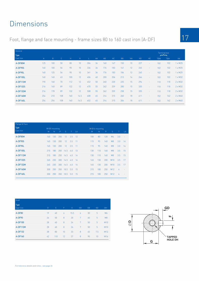
17
Dimensions
Foot, flange and face mounting - frame sizes 80 to 160 cast iron (A-DF)
AA--DDFF8800MM
AA--DDFF9900SS
AA--DDFF9900LL
AA--DDFF110000LL
AA--DDFF111122MM
AA--DDFF113322SS
AA--DDFF113322MM
AA--DDFF116600MM
AA--DDFF116600LL
125
140
140
160
190
216
216
254
254
General
A
100
100
125
140
140
140
178
210
254
B
50
56
56
63
70
89
89
108
108
C
80
90
90
100
112
132
132
160
160
H
10
10
10
12
12
12
12
14.5
14.5
K KKL AA AB AC BB HA HD TBW
1 x M25
1 x M25
1 x M25
1 x M32
2 x M32
2 x M32
2 x M32
2 x M40
2 x M40
304
336
361
406
452
470
508
608
652
34
36
36
40
50
55
55
65
65
160
176
176
200
240
262
262
314
314
167
183
183
206
220
259
259
315
315
150
161
186
213
225
200
238
260
304
10
12
12
14
15
15
15
18
18
227
245
245
266
294
335
335
411
411
102
102
102
102
110
110
110
152
152
102
102
102
102
118
118
118
162
162
TBH
IM B5 mounting
165
165
165
215
215
265
265
300
300
M
130
130
130
180
180
230
230
250
250
N
200
200
200
250
250
300
300
350
350
P
12
11
11
13
14
14
14
15
15
LA
12
12
12
14.5
14.5
14.5
14.5
18.5
18.5
S
3.5
3.5
3.5
4.0
4.0
4.0
4.0
5.0
5.0
T
IM B14 mounting
100
115
115
130
130
165
165
215
215
M
80
95
95
110
110
130
130
180
180
N
120
140
140
160
160
200
200
250
250
P
-
14
14
15
15
17
17
-
-
LA
M6
M8
M8
M8
M8
M10
M10
M12
M12
S
3.0
3.0
3.0
3.5
3.5
3.5
3.5
4
4
T
TTyyppee
Shaft
For tolerance details and notes - see page 26
AA--DDFF8800
AA--DDFF9900
AA--DDFF110000
AA--DDFF111122MM
AA--DDFF113322
AA--DDFF116600
19
24
28
28
38
42
D
M6
M8
M10
M10
M12
M16
DH
6
8
8
8
10
12
F
40
50
60
60
80
110
E
15.5
20
24
24
33
37
G
30
40
50
50
65
90
EB
TAPPED
HOLE DH
F
D
GD
G
AA--DDFF8800MM
AA--DDFF9900SS
AA--DDFF9900LL
AA--DDFF110000LL
AA--DDFF111122MM
AA--DDFF113322SS
AA--DDFF113322MM
AA--DDFF116600MM
AA--DDFF116600LL
6
7
7
7
8
8
GDCast iron
5
5
5
5
7.5
10
ED
Terminal box}
TTyyppee
Cast iron
TTyyppee
Cast iron
Flange & Face
HE
-
-
-
-
-
-
-
-
-

18
Dimensions
Foot, flange and face mounting - frame sizes 71 to 160 cast iron (B-DF)
IM B3IM 1001
Mounting options
IM B14/IM B34IM 3601/IM 2101
Mounting options
IM B5/IM B35IM 3001/IM 2001
Mounting options
B CRS
L
EBTBW
E C
BB
KKED
L
LA
P N
T
A CRS
AB
AA
K
HA
HHE
HD
TBH
AC
AA
4 HOLES SON M PCD
45°
L
LA
P N
T
HOLES SON M PCD
45°

19
Dimensions
Foot, flange and face mounting - frame sizes 71 to 160 cast iron (B-DF)
BB--DDFF7711MM
BB--DDFF8800MM
BB--DDFF9900SS
BB--DDFF9900LL
BB--DDFF110000LL
BB--DDFF111122MM
BB--DDFF113322SS
BB--DDFF113322MM
BB--DDFF116600MM
BB--DDFF116600LL
112
125
140
140
160
190
216
216
254
254
General
A
90
100
100
125
140
140
140
178
210
254
B
45
50
56
56
63
70
89
89
108
108
C
71
80
90
90
100
112
132
132
160
160
H
7
10
10
10
12
12
12
12
14.5
14.5
K KKAA AB AC BB HA HD TBW
1 x M20
1 x M25
1 x M25
1 x M25
1 x M32
2 x M32
2 x M32
2 x M32
2 x M40
2 x M40
32
34
36
36
40
45
55
55
65
65
144
160
176
176
200
226
262
262
314
314
136
156
176
176
196
220
259
259
314
314
120
130
130
155
176
180
200
238
260
304
8
10
12
12
14
15
18
18
20
20
190
211
238
238
262
295
335
335
411
411
94
94
102
102
102
110
110
110
152
152
94
94
102
102
102
118
118
118
162
162
TBH
IM B5 mounting
130
165
165
165
215
215
265
265
300
300
M
110
130
130
130
180
180
230
230
250
250
N
160
200
200
200
250
250
300
300
350
350
P
10
12
11
11
13
14
14
14
15
15
LA
10
12
12
12
14.5
14.5
14.5
14.5
18.5
18.5
S
3.5
3.5
3.5
3.5
4.0
4.0
4.0
4.0
5.0
5.0
T
IM B14 mounting
85
100
115
115
130
130
165
165
215
215
M
70
80
95
95
110
110
130
130
180
180
N
105
120
140
140
160
160
200
200
250
250
P
-
-
14
14
15
15
17
17
-
-
LA
M6
M6
M8
M6
M8
M8
M10
M10
M12
M12
S
2.5
3.0
3.0
3.0
3.5
3.5
3.5
3.5
4
4
T
TTyyppee
Shaft
For tolerance details and notes - see page 26
BB--DDFF7711
BB--DDFF8800
BB--DDFF9900
BB--DDFF110000
BB--DDFF111122MM
BB--DDFF113322
BB--DDFF116600
4
19
24
28
28
38
42
D
M5
M6
M8
M10
M10
M12
M16
DH
5
6
8
8
8
10
12
F
30
40
50
60
60
80
110
E
11
15.5
20
24
24
33
37
G
25
30
40
50
50
65
90
EB
TAPPED
HOLE DH
F
D
GD
G
BB--DDFF7711MM
BB--DDFF8800MM
BB--DDFF9900SS
BB--DDFF9900LL
BB--DDFF110000LL
BB--DDFF111122MM
BB--DDFF113322SS
BB--DDFF113322MM
BB--DDFF116600MM
BB--DDFF116600LL
5
6
7
7
7
8
8
GDCast iron
2.5
5
5
5
5
7.5
10
ED
Terminal box}
TTyyppee
Cast iron
TTyyppee
Cast iron
Flange & Face
HE
-
-
-
-
-
-
-
-
-
-
L
242
284
308
333
380
394
470
508
608
652

20
Dimensions
Foot and flange mounting - frame sizes 180 to 355 cast iron (A/AU-DF)
IM B3IM 1001
Mounting options
IM B5/IM B35IM 3001/IM 2001
Mounting options
B CRS
L
EBTBW
E C
BB
KKED
L
LA
P N
T
A CRS
AB
AA
K
HA
HHE
HD
TBH
AC
AA
4 HOLES SON M PCD
45°
8 HOLES SON M PCD (1)
22.5°
8 holes at 22.5° for flanges to suit 225 frames and above to European specification
Up to 200 frame
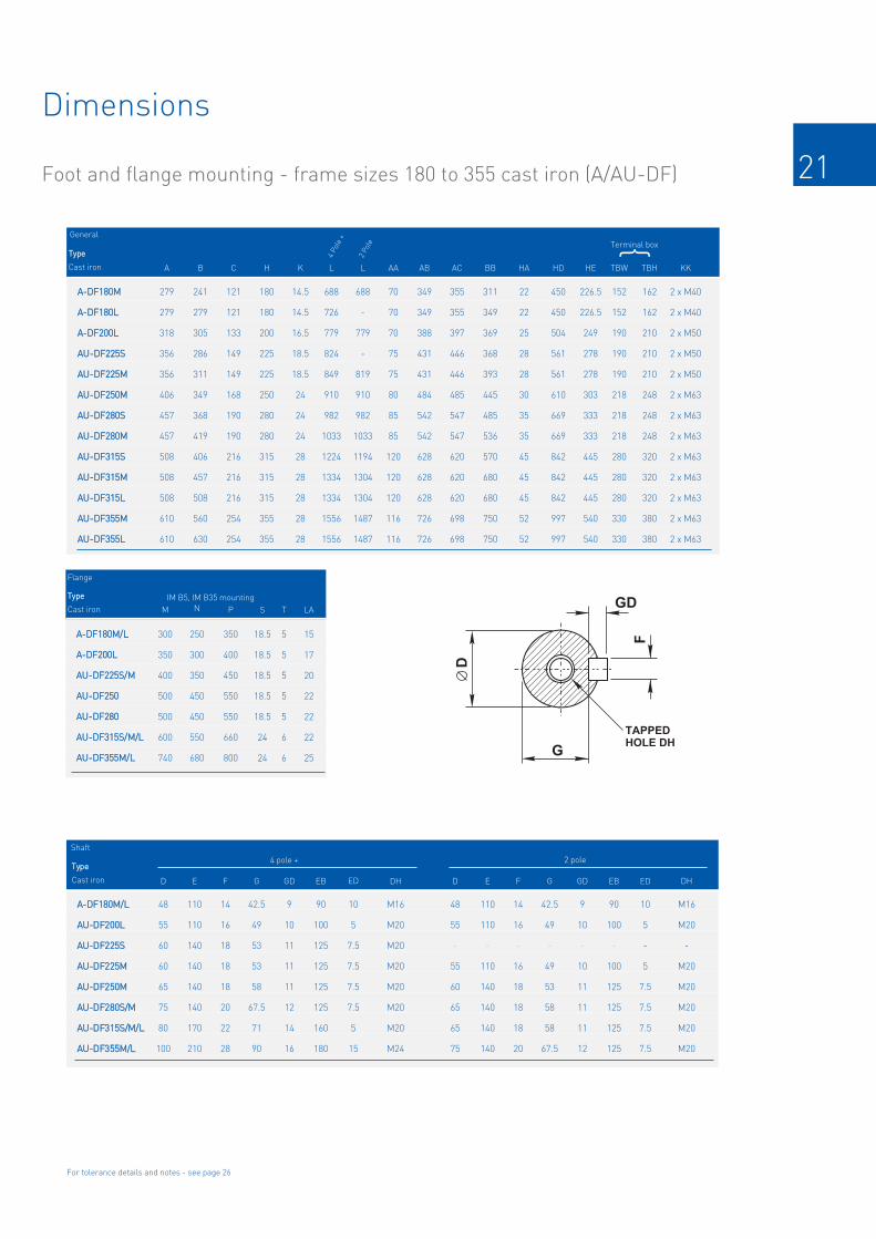
21
Dimensions
Foot and flange mounting - frame sizes 180 to 355 cast iron (A/AU-DF)
For tolerance details and notes - see page 26
TAPPED
HOLE DH
F
D
GD
G
AA--DDFF118800MM
AA--DDFF118800LL
AA--DDFF220000LL
AAUU--DDFF222255SS
AAUU--DDFF222255MM
AAUU--DDFF225500MM
AAUU--DDFF228800SS
AAUU--DDFF228800MM
AAUU--DDFF331155SS
AAUU--DDFF331155MM
AAUU--DDFF331155LL
AAUU--DDFF335555MM
AAUU--DDFF335555LL
279
279
318
356
356
406
457
457
508
508
508
610
610
GeneralTerminal box
A
241
279
305
286
311
349
368
419
406
457
508
560
630
B
121
121
133
149
149
168
190
190
216
216
216
254
254
C
180
180
200
225
225
250
280
280
315
315
315
355
355
H
14.5
14.5
16.5
18.5
18.5
24
24
24
28
28
28
28
28
K
2 x M40
2 x M40
2 x M50
2 x M50
2 x M50
2 x M63
2 x M63
2 x M63
2 x M63
2 x M63
2 x M63
2 x M63
2 x M63
KK
688
726
779
824
849
910
982
1033
1224
1334
1334
1556
1556
L
70
70
70
75
75
80
85
85
120
120
120
116
116
AA
349
349
388
431
431
484
542
542
628
628
628
726
726
AB
355
355
397
446
446
485
547
547
620
620
620
698
698
AC
311
349
369
368
393
445
485
536
570
680
680
750
750
BB
22
22
25
28
28
30
35
35
45
45
45
52
52
HA
450
450
504
561
561
610
669
669
842
842
842
997
997
HD
162
162
210
210
210
248
248
248
320
320
320
380
380
TBH
152
152
190
190
190
218
218
218
280
280
280
330
330
TBW
IM B5, IM B35 mounting
300
350
400
500
500
600
740
M
250
300
350
450
450
550
680
N
350
400
450
550
550
660
800
P
15
17
20
22
22
22
25
LA
18.5
18.5
18.5
18.5
18.5
24
24
S
5
5
5
5
5
6
6
T
AA--DDFF118800MM//LL
AAUU--DDFF220000LL
AAUU--DDFF222255SS
AAUU--DDFF222255MM
AAUU--DDFF225500MM
AAUU--DDFF228800SS//MM
AAUU--DDFF331155SS//MM//LL
AAUU--DDFF335555MM//LL
Shaft
48
55
60
60
65
75
80
100
D
M16
M20
-
M20
M20
M20
M20
M20
DH
14
16
18
18
18
20
22
28
F
42.5
49
53
53
58
67.5
71
90
G
90
100
125
125
125
125
160
180
EB
48
55
_
55
60
65
65
75
D
110
110
_
110
140
140
140
140
E
14
16
_
16
18
18
18
20
F
42.5
49
_
49
53
58
58
67.5
G
110
110
140
140
140
140
170
210
E
90
100
_
100
125
125
125
125
EB
9
10
11
11
11
12
14
16
GD
9
10
_
10
11
11
11
12
GD
10
5
7.5
7.5
7.5
7.5
5
15
ED
10
5
-
5
7.5
7.5
7.5
7.5
ED
M16
M20
M20
M20
M20
M20
M20
M24
DH
2 pole4 pole +
HE
226.5
226.5
249
278
278
303
333
333
445
445
445
540
540
688
-
779
-
819
910
982
1033
1194
1304
1304
1487
1487
L
4 Pole +
2 Pole
AA--DDFF118800MM//LL
AA--DDFF220000LL
AAUU--DDFF222255SS//MM
AAUU--DDFF225500
AAUU--DDFF228800
AAUU--DDFF331155SS//MM//LL
AAUU--DDFF335555MM//LL
}TTyyppee
Cast iron
TTyyppee
Cast iron
TTyyppee
Cast iron
Flange

22
Dimensions
Foot and flange mounting - frame sizes 180 to 355 cast iron (B/BU-DF)
IM B3IM 1001
Mounting options
IM B5/IM B35IM 3001/IM 2001
Mounting options
B CRS
L
EBTBW
E C
BB
KKED
L
LA
P N
T
A CRS
AB
AA
K
HA
HHE
HD
TBH
AC
AA
4 HOLES SON M PCD
45°
8 HOLES SON M PCD (1)
22.5°
8 holes at 22.5° for flanges to suit 225 frames and above to European specification
Up to 200 frame

23
Dimensions
Foot and flange mounting - frame sizes 180 to 355 cast iron (B/BU-DF)
For tolerance details and notes - see page 26
TAPPED
HOLE DH
F
D
GD
G
BB--DDFF118800MM
BB--DDFF118800LL
BB--DDFF220000LL
BBUU--DDFF222255SS
BBUU--DDFF222255MM
BBUU--DDFF225500MM
BBUU--DDFF228800SS
BBUU--DDFF228800MM
BBUU--DDFF331155SS
BBUU--DDFF331155MM
BBUU--DDFF331155LL
BBUU--DDFF335555MM
BBUU--DDFF335555LL
279
279
318
356
356
406
457
457
508
508
508
610
610
GeneralTerminal box
A
241
279
305
286
311
349
368
419
406
457
508
560
630
B
121
121
133
149
149
168
190
190
216
216
216
254
254
C
180
180
200
225
225
250
280
280
315
315
315
355
355
H
14.5
14.5
16.5
18.5
18.5
24
24
24
28
28
28
28
28
K
2 x M40
2 x M40
2 x M50
2 x M50
2 x M50
2 x M63
2 x M63
2 x M63
2 x M63
2 x M63
2 x M63
2 x M63
2 x M63
KK
688
726
771
824
849
910
982
1033
1208
1318
1318
1556
1556
L
70
70
70
75
75
80
85
85
120
120
120
116
116
AA
349
349
388
431
431
484
542
542
628
628
628
726
726
AB
355
355
397
446
446
485
547
547
620
620
620
698
698
AC
311
349
369
368
393
445
485
536
570
680
680
750
750
BB
22
22
25
28
28
30
35
35
45
45
45
52
52
HA
450
450
504
552
552
613
667
667
842
842
842
997
997
HD
162
162
210
210
210
248
248
248
320
320
320
380
380
TBH
152
152
190
190
190
218
218
218
280
280
280
330
330
TBW
IM B5, IM B35 mounting
300
350
400
500
500
600
740
M
250
300
350
450
450
550
680
N
350
400
450
550
550
660
800
P
15
17
20
22
22
22
25
LA
18.5
18.5
18.5
18.5
18.5
24
24
S
5
5
5
5
5
6
6
T
BB--DDFF118800MM//LL
BBUU--DDFF220000LL
BBUU--DDFF222255SS
BBUU--DDFF222255MM
BBUU--DDFF225500MM
BBUU--DDFF228800SS//MM
BBUU--DDFF331155SS//MM//LL
BBUU--DDFF335555MM//LL
Shaft
48
55
60
60
65
75
80
100
D
M16
M20
-
M20
M20
M20
M20
M20
DH
14
16
18
18
18
20
22
28
F
42.5
49
53
53
58
67.5
71
90
G
90
100
125
125
125
125
160
180
EB
48
55
_
55
60
65
65
75
D
110
110
_
110
140
140
140
140
E
14
16
_
16
18
18
18
20
F
42.5
49
_
49
53
58
58
67.5
G
110
110
140
140
140
140
170
210
E
90
100
_
100
125
125
125
125
EB
9
10
11
11
11
12
14
16
GD
9
10
_
10
11
11
11
12
GD
10
5
7.5
7.5
7.5
7.5
5
15
ED
10
5
-
5
7.5
7.5
7.5
7.5
ED
M16
M20
M20
M20
M20
M20
M20
M24
DH
2 pole4 pole +
HE
229
229
249
270
270
299
333
333
445
445
445
544.5
544.5
688
726
771
-
819
910
982
1033
1178
1288
1288
1487
1487
L
4 Pole +
2 Pole
BB--DDFF118800MM//LL
BB--DDFF220000LL
BBUU--DDFF222255SS//MM
BBUU--DDFF225500
BBUU--DDFF228800
BBUU--DDFF331155SS//MM//LL
BBUU--DDFF335555MM//LL
}Flange
TTyyppee
Cast iron
TTyyppee
Cast iron
TTyyppee
Cast iron

24
Dimensions
Foot and flange mounting - frame sizes 355LB to 450 cast iron (BU-DF)
TBW
L
EBED
E C
BB
B1
B2
AC
TBH
AA
A CRS
AB
HD
H
HA
K
KK
TBW
L
EBED
E C
BB
B1
B2
AC
TBH
AA
A CRS
AB
HD
H
HA
K
KK
IM B3IM 1001
Mounting options
IM B35IM 2001
Mounting options
8 HOLES SON M PCD (1)
22.5°
L
LA
P N
T
8 HOLES SON M PCD (1)
22.5°
L
LA
P N
T

25
Dimension
Foot and flange mounting - frame sizes 355LB to 450 cast iron (BU-DF)
TAPPED
HOLE DH
F
D
GD
G
BBUU--DDFF335555BB ++
BBUU--DDFF440000MM
BBUU--DDFF440000LL
BBUU--DDFF445500MM
BBUU--DDFF445500LL
630
686
686
800
800
GeneralTerminal box
A
800
630
630
900
900
B1
224
280
280
250
250
C
355
400
400
450
450
H
35
36
36
36
36
K
3 x M63
3 x M63
3 x M63
3 x M63
3 x M63
KK
1898
1881
1881
2200
2200
L
116
120
120
150
150
AA
760
806
806
950
950
AB
745
860
860
950
950
AC
1140
1090
1090
1200
1200
BB
52
52
55
62
62
HA
1120
1080
1080
1400
1400
HD
572
485
485
530
530
TBH
392
430
430
460
460
TBW
IM B5, IM B35 mounting
840
940
1040
M
780
880
980
N
800
1000
1100
P
-
-
-
LA
24
28
32
S
6
6
8
T
BBUU--DDFF335555
BBUU--DDFF440000
BBUU--DDFF445500
Shaft
110
110
130
D
M20
M24
M24
DH
28
28
32
F
86
100
119
G
160
180
180
EB
80
85
90
D
170
170
170
E
22
22
25
F
67.5
76
86
G
210
210
250
E
130
140
140
EB
16
16
16
GD
14
14
14
GD
5
15
15
ED
5
15
15
ED
M24
M24
M24
DH
2 pole4 pole +
1863
1820
1820
2050
2050
L
4 Pole
2 Pole
BBUU--DDFF335555
BBUU--DDFF440000
BBUU--DDFF445500
}TTyyppee
Cast iron
TTyyppee
Cast iron
TTyyppee
Cast iron
Flange
1918
1881
1881
2200
2200
L
6, 8 Pole
-
710
710
1000
1000
B2
For tolerance details and notes - see page 26

26
Dimension pages notes & mounting codes
Page notes
Horizontal shaft:Horizontal shaft:
Vertical shaft:Vertical shaft:
IM B3IM B3IM 1001IM 1001
foot mounted
IM B5IM B5IM 3001IM 3001
flange at DEno feet
IM B14IM B14IM 3601 IM 3601 face at DE
no feet
IM B6IM B6IM 1051IM 1051
foot wall mounted withfeet on left-hand sidewhen viewed from DE
IM B7IM B7IM 1061IM 1061
foot wall mounted withfeet on right-hand sidewhen viewed from DE
IM B8IM B8IM 1071IM 1071
ceiling mountedwith feet
above motor
IM V1IM V1IM 3011IM 3011
flange at DEshaft down
no feet
IM V3IM V3IM 3031IM 3031
flange at DEshaft upno feet
IM V5IM V5IM 1011IM 1011
vertical footwall mountedshaft down
IM V6IM V6IM 1031IM 1031
vertical footwall mounted
shaft up
IM V18IM V18IM 3611IM 3611
face at DEshaft down
no feet
IM V19IM V19IM 3631IM 3631
face at DEshaft upno feet
110
130
230 to 250
300
350
450
550
680
FFllaannggee
j6
j6
j6
j6
j6
j6
j6
js6
DDiimm NN
+0.013
–0.009
+0.014
–0.011
+0.016
–0.013
+0.016
-0.016
+0.018
-0.018
+0.020
-0.020
+0.022
-0.022
+0.025
-0.025
TTooll LLiimmiittss
70 and 80
95 and 110
130
230
FFaaccee
j6
j6
j6
j6
DDiimm NN
+0.012
–0.007
+0.013
–0.009
+0.014
–0.011
+0.016
–0.013
TTooll LLiimmiittss
TAPPED
HOLE DH
F
D
GD
G
All dimensions in millimetres
Cable entry can be arranged in any one of fourpositions at 90° intervals
Dimensions should not be used for installationpurposes unless specially endorsed
11 to 14
19 to 28
38 to 48
55 to 80
85 to 110
SShhaafftt
j6
j6
k6
m6
m6
DDiimm DD
+0.008
–0.003
+0.009
–0.004
+0.018
+0.002
+0.030
+0.011
+0.035
+0.013
TTooll LLiimmiittss
IIEECC 6600007722
B5 mounted motors have suffix ‘-D’ in the frame reference, eg A-DA132MA-D and B3/B5mounted motors have suffix ‘-H’ in the framereference, eg A-DA132MA-H
B14 mounted motors have suffix ‘C’ in the frame reference, eg A-DA132MA-C and B3/B14mounted motors have suffix ‘-H’ in the framereference, eg A-DA132MA-H
Note355LB frame and above, flange only availablewhen B35 mounted (foot & flange).
IIEECC 6600007722
Mounting codes
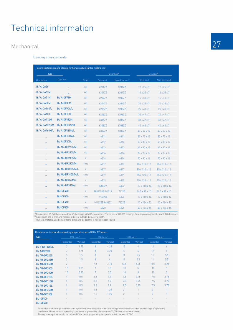
27
FFrraammee Net weight kg Gross weight kg
Cast ironAluminium
Net weight kg Gross weight kgFFrraammee
Technical information
Mechanical
__
__
BB // AA--DDFF7711MM
BB // AA--DDFF8800MM
BB // AA--DDFF9900SS//LL
BB // AA--DDFF110000LL
BB // AA--DDFF111122MM
BB // AA--DDFF113322SS//MM
BB // AA--DDFF116600MM//LL
BB // AA--DDFF118800MM//LL
BB // AA--DDFF220000LL
BB // AAUU--DDFF222255SS//MM
BB // AAUU--DDFF225500SS//MM
BB // AAUU--DDFF228800SS//MM
BB // AAUU--DDFF228800SS//MM
BB // AAUU--DDFF331155SS//MM//LL
BB // AAUU--DDFF331155SS//MM//LL
BB // AAUU--DDFF335555MM//LL
BB // AAUU--DDFF335555MM//LL
BBUU--DDFF440000
BBUU--DDFF440000
BBUU--DDFF445500
BBUU--DDFF445500
BBeeaarriinngg rreeffeerreenncceess aanndd ooiillsseeaallss ffoorr hhoorriizzoonnttaallllyy mmoouunntteedd mmoottoorrss oonnllyy
All
All
All
All
All
All
All
All
All
All
All
All
All
2
4 up
2
4 up
2
4 up
2
4 up
2
4 up
(1) Frame sizes 56-160 have sealed for life bearings with C3 clearances. Frame sizes 180-355 bearings have regreasing facilities with C3 clearance.(2) Sizes given are in mm and represent bore x outside diameter x width.The seal material used on all frame sizes and all polarity is nitrile rubber (NBR).
TTyyppee
BB // AA--DDAA5566
BB // AA--DDAA6633MM
BB // AA--DDAA7711MM
BB // AA--DDAA8800MM
BB // AA--DDAA9900SS//LL
BB // AA--DDAA110000LL
BB // AA--DDAA111122MM
BB // AA--DDAA113322SS//MM
BB // AA--DDAA116600MM//LL
__
__
__
__
__
__
__
__
__
__
__
__
__
__
Cast ironAluminium Poles
Bearings((11)) Oilseals((22))
Bearing arrangements
6201ZZ
6201ZZ
6202ZZ
6204ZZ
6205ZZ
6206ZZ
6306ZZ
6308ZZ
6309ZZ
6311
6312
6313
6314
6314
6317
6317
6319
6319
NU322
NU2194E &6219
NU326E
NU222E & 6222
6328
12 x 25 x 7
12 x 25 x 7
15 x 30 x 7
20 x 35 x 7
25 x 40 x 7
30 x 47 x 7
30 x 47 x 7
40 x 62 x 7
45 x 62 x 12
55 x 75 x 12
60 x 80 x 12
65 x 90 x 12
70 x 90 x 12
70 x 90 x 12
85 x 110 x 12
85 x 110 x 12
95 x 120 x 12
95 x 120 x 12
110 x 140 x 14
84.5 x 97 x 10
119 x 140 x 14
110 x 124 x 12
140 x 154 x 15
6201ZZ
6201ZZ
6202ZZ
6204ZZ
6205ZZ
6206ZZ
6306ZZ
6308ZZ
6309ZZ
6311
6312
6313
6314
6314
6317
6317
6319
6319
6322
7219B
6326
7222B
6328
Drive end Non-drive end Drive end Non-drive end
12 x 25 x 7
12 x 25 x 7
15 x 30 x 7
20 x 35 x 7
25 x 40 x 7
30 x 47 x 7
30 x 47 x 7
40 x 62 x 7
45 x 62 x 12
55 x 75 x 12
60 x 80 x 12
65 x 90 x 12
70 x 90 x 12
70 x 90 x 12
85 x 110 x 12
85 x 110 x 12
95 x 120 x 12
95 x 120 x 12
110 x 140 x 14
84.5 x 97 x 10
119 x 140 x 14
110 x 124 x 12
140 x 154 x 15
BB // AA--DDFF118800MM//LL
BB // AA--DDFF220000LL
BB // AAUU--DDFF222255SS
BB // AAUU--DDFF222255MM
BB // AAUU--DDFF225500MM
BB // AAUU--DDFF228800SS
BB // AAUU--DDFF228800MM
BB // AAUU--DDFF331155SS
BB // AAUU--DDFF331155MM
BB // AAUU--DDFF331155LL
BB // AAUU--DDFF335555MM
BB // AAUU--DDFF335555LL
BBUU--DDFF440000
BBUU--DDFF445500
RReelluubbrriiccaattiioonn iinntteerrvvaallss ffoorr ooppeerraattiinngg tteemmppeerraattuurree uupp ttoo 7700ooCC xx 110033 hhoouurrss
Horizontal Vertical Horizontal Vertical Horizontal Vertical Horizontal Vertical
3
3
3
3
2
1.5
1.5
1
1
1
1
1
-
-
1.75
1.75
1.5
1.5
1
0.75
0.75
0.5
0.5
0.5
0.5
0.5
-
-
8
8
8
8
7.5
7
7
3.8
3.8
3.8
2.5
2.5
-
-
4.25
4.25
4
4
3.75
3.5
3.5
1.9
1.9
1.9
1.25
1.25
-
-
12
12
11
11
10.5
10
10
7.5
7.5
7.5
2
2
-
-
6
6
5.5
5.5
5.25
5
5
3.75
3.75
3.75
1
1
-
-
12
12
11
11
10.5
10
10
7.5
7.5
7.5
2
2
-
-
6
6
5.5
5.5
5.25
5
5
3.75
3.75
3.75
1
1
-
-
Sealed for life bearings are fitted with a premium quality grease to ensure exceptional reliability under a wide range of operatingconditions. Under normal operating conditions, a grease life of more than 25,000 hours can be achieved.The regreasing time should be reduced if the bearing operating temperature is in excess of 70°C.
TTyyppee 3000 min-1 1500 min-1 1000 min-1 750 min-1
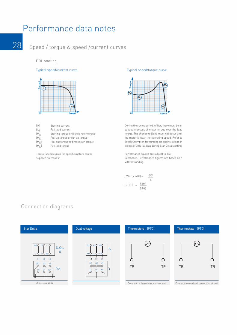
28
Performance data notes
Speed / torque & speed /current curves
DOL starting
Typical speed/current curve Typical speed/torque curve
(IA) Starting current(IN) Full load current(MA) Starting torque or locked rotor torque(MS) Pull up torque or run up torque(MK) Pull out torque or breakdown torque(MN) Full load torque
Torque/speed curves for specific motors can besupplied on request.
J (WK2 or WR2) =
J in lb ft2 =
GD2
4kgm2
0.042
During the run up period in Star, there must be anadequate excess of motor torque over the loadtorque. The change to Delta must not occur untilthe motor is near the operating speed. Refer toBrook Crompton for running up against a load inexcess of 70% full load during Star Delta starting.
Performance figures are subject to IECtolerances. Performance figures are based on a400 volt winding.
Connection diagrams
W2
D.O.L
∆
Y∆
U2 V2
W2 U2 V2
U1 V1 W1
L1 L2 L3
U1 V1 W1
W2 U2 V2
W2 U2 V2
U1 V1 W1
L1 L2 L3
U1 V1 W1
∆
Y
SSttaarr DDeellttaa DDuuaall vvoollttaaggee
Motors => 4kW
TThheerrmmiissttoorrss -- ((PPTTCC))
Connect to thermistor control unit.
TTPP TTPP
TThheerrmmoossttaattss -- ((PPTTOO))
Connect to overload protection circuit
TTBB TTBB

29
Notes

Brook CromptonSt Thomas’ Road HuddersfieldWest Yorkshire HD1 3LJ UKTel: +44 (0) 1484 557200Fax: +44 (0) 1484 557201E-mail: [email protected]: www.brookcrompton.com
dh1002/*/*/03/14 20121E Issue 1.2 (Series 10)© Copyright 2014. Brook Crompton. All rights reserved.
Every care has been taken to ensure the accuracy of the
information contained in this publication, but, due to a policy of
continuous development and improvement the right is reserved
to supply products which may differ slightly from those
illustrated and described in this publication


![Public Input No. 140-NFPA 79-2016 [ Global Input ] · PDF filePublic Input No. 140-NFPA 79-2016 [ Global Input ] ... International Electrotechnical Commission, 3, ... IEC 60072–2,](https://static.fdocuments.in/doc/165x107/5a9f52a87f8b9a71178c9dd7/public-input-no-140-nfpa-79-2016-global-input-input-no-140-nfpa-79-2016-.jpg)


![inDEx [ ] · PDF fileCEi En50347 iEC 60072-1 iEC 60072-2 The coupling dimensions are in compliance with the following standards: unEL 13113-71 for the B3 mounting and for other frame](https://static.fdocuments.in/doc/165x107/5a9f52a87f8b9a71178c9dee/index-en50347-iec-60072-1-iec-60072-2-the-coupling-dimensions-are-in-compliance.jpg)