SERIE AD AD - Knife Gate Valves - CMO Valves
11
1 manufacturing the valve you need INSTRUCTIONS AND MAINTENANCE MANUAL - SERIE - AD AD Rev. 01 20-05-2019 KNIFE GATE VALVE - SERIE AD
Transcript of SERIE AD AD - Knife Gate Valves - CMO Valves
1 manufacturing the valve you need
INSTRUCTIONS AND MAINTENANCE MANUAL - SERIE - AD
ADR
ev. 01 20
-05-20
19K N I F E G A T E VA LV E - S E R I E A D

2 manufacturing the valve you need
KNIFE GATE VALVE - SERIE AD Rev .0
1-20-0
5-201920
2
INSTRUCTIONS AND MAINTENANCE MANUAL - SERIE - ADASSEMBLY
DIRECTIVES
Pressure Equipment Directive: (PED) ART 4.3 /CAT.1Explosive Atmospheres Directive (optional): (ATEX) CAT.3 ZONA 2 and 22 GD.
The AD valve complies with the Directive on Equipment and Protective Systems for Use in Explosive Atmospheres. In these cases the logo will appear on the iden-tification label. This label shows the exact classification of the zone in which the valve can be used. The user is responsible for its use in any other zone.
HANDLING
During the handling of the equipment, special attention must be paid to the fo-llowing points:
• SAFETY WARNING: Before handling the valve, check that the crane to be used is capable of withstanding its weight.
• To prevent damage, especially to the anti-corrosive protection, we recom-mend using soft straps to lift CMO Valves knife gate valves. These straps must be fitted to the top of valve, around its body.
• Do not lift the valve or hold it by the actuator. Lifting the valve by the actuator can lead to operating problems as it is not designed to withstand the valve’s weight.
• Do not lift the valve or hold it by the flow passage area. The valve’s seal is located in this area. If the valve is held and lifted by this area it can damage the surface and the O-ring seal and lead to leakage problems whilst the valve is operating.
INSTALLATION
In order to avoid personal injury and other types of damage (to property, the plant, etc.), we recommend following these recom-mendations:
• The personnel responsible for handling and maintenance of the equipment must be qualified and trained in operations with this type of equipment. • Use appropriate personal protection (gloves, safety boots, goggles, helmet, high-visibility vest…). • Shut off all operating lines to the valve and put up a warning sign. • Completely isolate the valve from the whole process. • Depressurise the process. • Drain all the line fluid through the valve. • Use hand tools not electric tools during installation and maintenance, in accordance with EN13463-1(15).
Before installation, inspect the valve body and components for any possible damage occurred during transport or storage. Make sure that the valve’s inside cavities are clean. Inspect the pipes and the flanges to make sure they contain no foreign ma-terial and are clean.
The AD valve is unidirectional and has an arrow marked on the body indicating the flow direction. The word SEAT is also marked on one side of the body (near the stuffing) to indicate the side where the sealing joint is located.
IMPORTANT: The valve must always be installed in the OPEN position.
3www.cmovalves.com
KNIFE GATE VALVE - SERIE AD Rev .0
1-20-0
5-2019
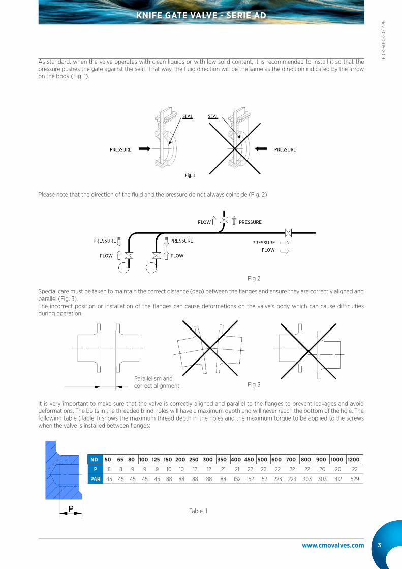
As standard, when the valve operates with clean liquids or with low solid content, it is recommended to install it so that the pressure pushes the gate against the seat. That way, the fluid direction will be the same as the direction indicated by the arrow on the body (Fig. 1).
Please note that the direction of the fluid and the pressure do not always coincide (Fig. 2)
It is very important to make sure that the valve is correctly aligned and parallel to the flanges to prevent leakages and avoid deformations. The bolts in the threaded blind holes will have a maximum depth and will never reach the bottom of the hole. The following table (Table 1) shows the maximum thread depth in the holes and the maximum torque to be applied to the screws when the valve is installed between flanges:
Special care must be taken to maintain the correct distance (gap) between the flanges and ensure they are correctly aligned and parallel (Fig. 3). The incorrect position or installation of the flanges can cause deformations on the valve’s body which can cause difficulties during operation.
Parallelism andcorrect alignment.
ND 50 65 80 100 125 150 200 250 300 350 400 450 500 600 700 800 900 1000 1200
P 8 8 9 9 9 10 10 12 12 21 21 22 22 22 22 22 20 20 22
PAR 45 45 45 45 45 88 88 88 88 88 152 152 152 223 223 303 303 412 529
Table. 1
Fig 3
Fig 2
4 manufacturing the valve you need
KNIFE GATE VALVE - SERIE AD Rev .0
1-20-0
5-201920
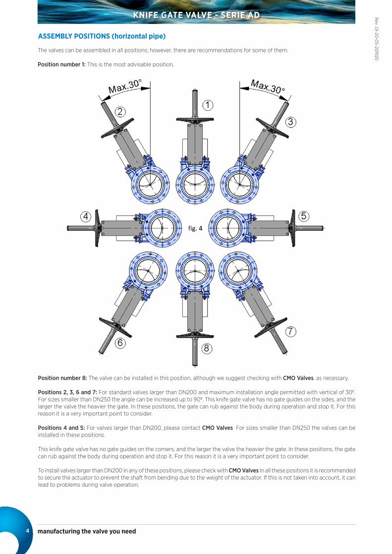
The valves can be assembled in all positions; however, there are recommendations for some of them.
Position number 1: This is the most advisable position.
Position number 8: The valve can be installed in this position, although we suggest checking with CMO Valves. as necessary.
Positions 2, 3, 6 and 7: For standard valves larger than DN200 and maximum installation angle permitted with vertical of 30º. For sizes smaller than DN250 the angle can be increased up to 90º. This knife gate valve has no gate guides on the sides, and the larger the valve the heavier the gate. In these positions, the gate can rub against the body during operation and stop it. For this reason it is a very important point to consider.
Positions 4 and 5: For valves larger than DN200, please contact CMO Valves For sizes smaller than DN250 the valves can be installed in these positions.
This knife gate valve has no gate guides on the corners, and the larger the valve the heavier the gate. In these positions, the gate can rub against the body during operation and stop it. For this reason it is a very important point to consider.
To install valves larger than DN200 in any of these positions, please check with CMO Valves In all these positions it is recommended to secure the actuator to prevent the shaft from bending due to the weight of the actuator. If this is not taken into account, it can lead to problems during valve operation.
ASSEMBLY POSITIONS (horizontal pipe)

5www.cmovalves.com
KNIFE GATE VALVE - SERIE AD Rev .0
1-20-0
5-2019
The valves can be assembled in all positions; however, recommendations do exist for some of them.
Positions numbers 1, 2, and 3: In these positions it is recommended to secure the actuator as its weight can cause the shaft to bend. If this is not taken into account, it can lead to problems during operation.
Once the valve has been installed, check that all the screws and nuts have been correctly tightened and that the whole valve action system has been correctly adjusted (electrical connections, pneumatic connections, instruments, etc.).
Even if the valve has been assembled and tested at C.M.O.’s facilities, the screws on the stuffing tend to come loose during handling and transport and must be re-tightened.
Once the valve is installed in the pipeline and it has been pressurised, it is very important to check for any leakages from the stuffing to the atmosphere.
In the event of a leakage, tighten the screws on the stuffing crosswise until the leakage stops, ensuring that there is no contact between the stuffing and the gate.
A very high tightening torque on the stuffing’s screws can lead to problems, such as an increase in the valve’s torque, reduction in the packing’s working life, or the breaking of the stuffing. The tightening torques are indicated in Table 2.
Once the valve is in place, check that the flanges and electrical and pneumatic connections are secure. If electrical connections are present or you are in an ATEX zone, earth connections must be made before starting.
In an ATEX zone, check the continuity between the valve and the pipe (EN 12266-2, annex B, points B.2.2.2. and B.2.3.1.). Check the pipe’s earth connection and the conductivity between the outlet and inlet pipes
ASSEMBLY POSITIONS (vertical/leaning pipe)
WHEEL (rising stem, non-rising stem and geared) To operate the valve: Turn the wheel clockwise to close or anticlockwise to open.
CHAIN WHEELTo operate the valve pull one of the chain’s vertical drops, taking into account that sealing is carried out when the chain wheel turns clockwise.
LEVER First loosen the position locking clamp located on the yoke. Once it is unlocked, raise the lever to open it or lower to close it. Lock the lever again to complete the operation
PNEUMATIC (double and single acting)The CMO Valves pneumatic actuators are designed to be connected to a 6 kg/cm² pneumatic network, although these cylinders support up to 10 kg/cm². The pressurised air used for the pneumatic actuator must be correctly filtered and lubricated. This type of actuator does not require any adjustment, due to the fact that the pneumatic cylinder is designed for the exact stroke required by the valve.
HYDRAULICThe CMO Valves hydraulic actuators are designed to operate at a standard pressure of 135 kg/cm². This type of actuator does not require any adjustment, due to the fact that the hydraulic cylinder is designed for the exact stroke required by the valve.
MOTORISED (rising, non-rising stem)If the valve is fitted with a motorised actuator, the instructions of the supplier of the electric actuator will be included.
PARES DE APRIETE PARA TORNILLOS EN PRENSAESTOPAS
DN50 a DN125 25 Nm
DN150 a DN300 30 Nm
DN350 a DN1200 35 Nm
ACTUATORS
Tabla. 2
fig. 5

6 manufacturing the valve you need
KNIFE GATE VALVE - SERIE AD Rev .0
1-20-0
5-201920
MAINTENANCE
• The personnel responsible for the installation, operation and maintenance of the valves must be qualified and trained in the operation of similar valves.
• Appropriate personal protection must be used (gloves, safety boots, goggles, hardhat…). • Shut off all operating lines to the valve and put up a warning sign. • Completely isolate the valve from the process. • Fully depressurise the process. • Drain all the line fluid through the valve. • Use hand tools not electric tools during the installation and maintenance, in accordance with EN13463-1(15). • The only maintenance required in this type of valve is to change the seat’s rubber joint (if soft seated valve is used) and the packing. We recommend checking the seal every 6 months, although its working life will depend on the working conditions of the valve, such as: pressure, temperature, number of operations, fluid composition, among others.
In an ATEX zone, electrostatic charges may be present inside the valve, which can cause explosions. The user is responsible for minimising the risks. Maintenance personnel must consider the risks of explosion and ATEX training is recommended. If the fluid transported constitutes an internal explosive atmosphere, the user must regularly check the installation’s correct watertight integrity. Regular cleaning of the valve to prevent accumulation of dust. Assemblies not permitted at the end of the line. Avoid painting the products supplied.
• To work under suitable safety conditions, the magnetic and electrical elements must be at rest and the air tanks depressurized. Likewise, also the electrical control cabinets must be out of service. The maintenance personnel must be aware of the safety regulations and only work can be started under the order of the on-site safety personnel
• The safety areas must be clearly marked and the support of auxiliary equipment (ladders, scaffolding, etc.) on levers or moving parts must be avoided so that the guillotine can move.
• In equipment with spring return drives, the guillotine must be mechanically locked and only unlocked when the drive is pressurized.
• In equipment with electric drive, it is recommended to disconnect it from the network in order to access the moving parts without any risk.
In order to prevent personal injury and other types of damage (in the plant, etc,) we recommend following these recommendations:
IMPORTANT SAFETY ASPECTS
Wheel Rising-stem
Wheel NON-rising stem
Pneumatic actuator
Electric-motor actuator
Hydraulic actuator
Geared wheel
LUBRICATION It is recommended to lubricate the stem twice a year by removing the cap from the bonnet and filling it with grease up to half its volume. After maintenance in an ATEX zone, it is necessary to check the electrical continuity between the pipe and the rest of the valve’s components, such as the body, gate, stem, etc; Standard EN 12266-2, Annex B, points B.2.2.2. and B.2.3.1.)
fig. 6

7www.cmovalves.com
KNIFE GATE VALVE - SERIE AD Rev .0
1-20-0
5-2019
Ring
Sealing joint
The following aspects must be considered:
• To obtain greater watertight integrity in the stainless steel bodies, it is advisable to apply plastic glue to the joint housing. This is not necessary if the body is painted.
• With the rubber seal tab pointing outwards, make a circle and then form a heart shape. • It is recommendable to insert the joint in the top part, press the arched part and insert the seal into the housing.
1. Make sure there is absolutely no pressure and fluid in the installation.
2. Remove the valve from the pipeline.
3. Remove the actuator and safety guards (if present) by unscrewing and removing the bolts connecting the stem to the gate and the support plate to the body.
4. Remove the stuffing (4).
5. Remove the old packing (5 and 6) taking care not to damage its rubber strip.
6. Remove the gate (2) carefully without losing the nylon slides (3).
7. Clean the inside surfaces of the valve.
8. Remove the ring (8) that secures the sealing joint (9). For this purpose, apply a few sharp knocks to the outside with a bronze object at the base of the ring until it comes out. .
9. Remove the old seal (9) and clean its housing
10. Fit a new sealing joint (9) with the same dimensions as the old one or use the dimensions shown below (table 3). .
11. Insert the retaining ring (8) in its original position as indicated:
• Place the retaining ring (8) in perfect alignment parallel to the sealing joint.
• Push the ring (8) as a whole towards the base of the channel.
12. alve assembly will be performed in reverse order to disassembly.
*Nota: Los números entre paréntesis, hacen referencia al listado de componentes de la tabla 7.
REPLACING THE SEALING JOINT (Teflon or PTFE)
REPLACING THE SEAL (except metal/metal)
PETROLEUM JELLY
Saybolt colour ASTM D-156 15
Melting point (ºC) ASTM D-127 60
Viscosity at 100ºC ASTM D-445 5
Penetration 25ºC mm./10 ASTM D-937 165
Silicone content None
Pharmacopeia BP OK
Table. 4
Table. 3
*Note: During the assembly of the new sealing joint it is recommended to apply petroleum jelly to the seal to facilitate the assembly process and the correct operation of the valve (do not use oil or grease); table 4 below shows details of the petroleum jelly used by CMO Valves
ND 50 65 80 100 125 150 200 250 300 350 400 450 500 600 700 800 900 1000 1200
Long. 190 250 290 370 445 530 690 845 1005 1175 1350 1520 1710 2020 2300 2680 3030 3367 3995
fig. 6

8 manufacturing the valve you need
KNIFE GATE VALVE - SERIE AD Rev .0
1-20-0
5-201920
1. Make sure there is absolutely no pressure and fluid in the installation.
2. Place the valve in open position.
3. If the valve has safety protections, remove them.
4. Loosen the screws that connect the stem or rod to the gate.
5. Release the connection between the support plates and the body, remove the actuator.
6. Loosen and remove the stuffing (4).
7. Remove the old packing (5 and 6) using a pointed tool, taking care not to damage the surface of the gate (2).
8. Carefully clean the packing, making sure there are no residues anywhere so the new packing strips fit correctly.
9. Insert the new packing (5 and 6). During this operation it is very important for both ends to be perfectly joined. The packing dimensions are shown below (Table 5). As standard, C.M.O. valve packing is composed of 3 lines (2 stuffing lines and 1 rubber joint line in the middle).
10. Place the stuffing in its original position (step 6), making sure it does not touch the gate, carefully tighten all the screws crosswise and make sure the same distance is left between the gate and the stuffing on both sides.
11. Screw down the support plates and the stem, in reverse order to that described in steps 4 and 5.
12. Perform several manoeuvres with no load, checking the correct operation of the valve and ensuring the stuffing is correctly centred.
13. Pressurise the valve in the line and tighten the stuffing crosswise, enough to prevent leakages to the atmosphere.
REPLACING THE PACKING
*Note: : The numbers in brackets refer to the components list in Table 7.
DIAMETER PACKING RUBBER RING
DN50 2 lines of 8 mm² x 204 mm. 1 line of 8 mm² x 204 mm.
DN65 2 lines of 8 mm² x 234 mm. 1 line of 8 mm² x 234 mm.
DN80 2 lines of 8 mm² x 264 mm. 1 line of 8 mm² x 264 mm.
DN100 2 lines of 8 mm² x 304 mm. 1 line of 8 mm² x 304 mm.
DN125 2 lines of 8 mm² x 356 mm. 1 line of 8 mm² x 356 mm.
DN150 2 lines of 8 mm² x 406 mm. 1 line of 8 mm² x 406 mm.
DN200 2 lines of 8 mm² x 516 mm. 1 line of 8 mm² x 516 mm.
DN250 2 lines of 10 mm² x 636 mm. 1 line of 10 mm² x 636 mm.
DN300 2 lines of 10 mm² x 740 mm. 1 line of 10 mm² x 740 mm.
DN350 2 lines of 10 mm² x 810 mm. 1 line of 10 mm² x 810 mm.
DN400 2 lines of 10 mm² x 928 mm. 1 line of 10 mm² x 928 mm.
DN450 2 lines of 10 mm² x 1028 mm. 1 line of 10 mm² x 1028 mm.
DN500 2 lines of 14 mm² x 1144 mm. 1 line of 14 mm² x 1144 mm.
DN600 2 lines of 14 mm² x 1346 mm. 1 line of 14 mm² x 1346 mm.
*Note: If it is not possible to place a rubber joint in the middle, another packing line should be used instead.
Table. 5

9www.cmovalves.com
KNIFE GATE VALVE - SERIE AD Rev .0
1-20-0
5-2019
PNEUMATIC ACTUATOR MAINTENANCE
The pneumatic cylinders in our valves are manufactured and assembled at our premises. Maintenance for these cylinders is straightforward; if you need to replace any elements or have any questions, please ask CMO Valves. Below is an exploded diagram of the pneumatic actuator and a list of the cylinder’s components. The top cover and the support cover are usually made of aluminium, although pneumatic cylinders over Ø200 mm are made of cast iron GJS-400.
The maintenance kit normally includes: the bushing and its seals and the scraper, and if the customer wishes, the piston is also supplied. The steps to follow to replace these parts are shown below.
1. Position the valve in closed position and shut off the pneumatic circuit pressure.
2. Release the cylinder air input connections.
3. Release and remove the top cover (5), the casing (4) and the shafts (16).
4. Loosen the nut (14) which connects the piston (3) and the rod (1), and remove the pieces. Disassemble the cir-clip (10) and remove the bushing (7) with its joints (8, 9).
5. Release and remove the support cover (2), in order to remove the scraper (6).
6. Replace the damaged parts with new ones and assemble the actuator in reverse order to that described for disassembly.
PNEUMATIC ACTUATOR
POS. DESCRIPTION MATERIAL
1 SPINDLE AISI-304
2 SUPPORT COVER ALUMINIUM
3 PISTON S275JR + EPDM
4 CASING ALUMINIUM
5 TOP COVER ALUMINIUM
6 SCRAPER NITRILE
7 BUSHING NYLON
8 EXTERIOR O-RING NITRILE
9 INTERIOR O-RING NITRILE
10 CIR-CLIP STEEL
11 WASHER ST ZINC
12 O-RING NITRILE.
13 WASHER ST ZINC
14 SELF-LOCKING NUT 5.6 ZINC
15 O-RING NITRILE.
16 SHAFTS F-114 ZINC
17 WASHER ST ZINC
18 NUT 5.6 ZINC
19 BOLT 5.6 ZINC
20 WASHER ST ZINC
21 NUT 5.6 ZINC
22 BOLT A-2
23 SELF-LOCKING NUT A-2
24 PROTECTION S275JR
Tabla. 6

10 manufacturing the valve you need
KNIFE GATE VALVE - SERIE AD Rev .0
1-20-0
5-201920To ensure the valve is in optimum conditions of use after long periods of storage, it should be stored in a well-ventilated place at
temperatures below 30ºC.
It is not advisable, but if it is stored outside, the valve must be covered to protect it from heat and direct sunlight, with good ventilation to prevent humidity. The following aspects must be considered for storage purposes:
• The storage place must be dry and under cover. • It is not recommended to store the equipment outdoors with direct exposure to adverse weather conditions, such as rain,
wind, etc. Even less so if the equipment is not protected with packaging. • This recommendation is even more important in areas with high humidity and saline environments. Wind can carry dust and
particles which can come into contact with the valve’s moving parts and this can lead to operating difficulties. The actuator system can also be damaged due to the introduction of particles in the different elements.
• The equipment must be stored on a flat surface to avoid deformations. • If the equipment is stored without suitable packaging it is important to keep the valve’s moving parts lubricated, for this
reason it is recommended to carry out regular checks and lubrication. • Likewise, if there are any machined surfaces without surface protection it is important for some form of protection to be
applied to prevent the appearance of corrosion.
COMPONENTS LIST (manual valve)
POS. DESCRIPTION
1 BODY
2 GATE
3 SLIDES
4 STUFFING
5 PACKING
6 SEAL (PACKING)
7 SUPPORT PLATES
8 RING
9 SEALING JOINT
10 STEM
11 YOKE
12 STEM NUT
13 STOPPER NUT
14 WHEEL
15 BONNET NUT
16 BONNET
17 PROTECTION CAP
Table. 7
STORAGE

11www.cmovalves.com
KNIFE GATE VALVE - SERIE AD Rev .0
1-20-0
5-2019
NORTH AMERICA
SOUTH AMERICA
EUROPE
MIDDLE EAST
AFRICA
ASIA
AUSTRALIA& OCEANIA
www.cmovalves.com
CMO MADRID
C/ Rumania, 5 - D5 (P.E. Inbisa)28802 Alcalá de HenaresMadrid (Spain)
Tel.: (+34) 91 877 11 80Fax: (+34) 91 879 79 94
CMO HEADQUARTERSMAIN OFFICES & FACTORY
Amategi Aldea, 14220400 TolosaGuipuzcoa (Spain)
Tel.: (+34) 943 67 33 99Fax: (+34) 943 67 24 40
[email protected] www.cmovalves.com
CMO SOUTH AMERICA
Bodegas MersanAvenida Lo Espejo 01565 Pabellón 8, Local 0821-0823Santiágo de Chile (Chile)
Tel.: (+56 2) 255 94 775
[email protected] www.cmosudamerica.com