Serial ATA Flash Driveeflash.apacerus.com/SPEC/SATA/M.2/2280/SM210-M280_APM2T80SM… · Serial ATA...
18
RoHS Recast Compliant Serial ATA Flash Drive SM210-M280 Single-Side Product Specifications March 7, 2016 Version 1.1 Apacer Technology Inc. 1F, No.32, Zhongcheng Rd., Tucheng Dist., New Taipei City, Taiwan, R.O.C Tel: +886-2-2267-8000 Fax: +886-2-2267-2261 www.apacer.com
-
Upload
duonghuong -
Category
Documents
-
view
230 -
download
0
Transcript of Serial ATA Flash Driveeflash.apacerus.com/SPEC/SATA/M.2/2280/SM210-M280_APM2T80SM… · Serial ATA...

RoHS Recast Compliant
Serial ATA Flash Drive
SM210-M280 Single-Side Product Specifications
March 7, 2016
Version 1.1
Apacer Technology Inc.
1F, No.32, Zhongcheng Rd., Tucheng Dist., New Taipei City, Taiwan, R.O.C
Tel: +886-2-2267-8000 Fax: +886-2-2267-2261
www.apacer.com

M.2 2280 Flash Drive APM2T80SM21xxxGAS-3XTMGX
1 © 2016 Apacer Technology Inc. Rev. 1.1
Features:
Standard SATA Interface Compliance – Serial ATA Revision 3.2 compliance – SATA 6.0 Gbps interface – ATA-8 command set
Capacity – 32, 64, 128, 256 GB
Performance* – Burst read/write: 600 MB/sec – Sustained read: up to 505 MB/sec – Sustained write: up to 350 MB/sec – Random read (4K): up to 82,000 IOPS – Random write (4K): up to 79,000 IOPS
Flash Management – Built-in hardware ECC – Static/dynamic wear-leveling – Flash bad-block management – S.M.A.R.T. – Power failure management – ATA secure erase – TRIM
NAND Flash Type: MLC
MTBF: >1,000,000 hours
Temperature Range – Operating:
Standard: 0°C to 70°C Extended: -40°C to 85°C
– Storage: -40°C to 85°C
Supply Voltage
– 3.3 V ± 5%
Power Consumption* – Active mode: 745 mA – Idle mode: 75 mA
Connector Type – 75-pin SATA-based M.2 module pinout
Form Factor – M.2 2280 form factor
– Dimensions: 80.00x22.00x2.15, unit: ㎜
Shock & Vibration** – Shock:1,500 G – Vibration: 15 G
RoHS Recast Compliant (complies with 2011/65/EU standard)
DEVSLP (optional)
*Varies from capacities. The values for performances and power consumptions presented are typical and may vary depending on flash configurations or platform settings. The term idle refers to the standby state of the device. **Non-operating
M.2 2280 Flash Drive APM2T80SM21xxxGAS-3XTMGX
2 © 2016 Apacer Technology Inc. Rev. 1.1
Table of Contents
1. General Description .............................................................................. 3
2. Pin Assignments .................................................................................... 4
3. Product Specifications.......................................................................... 6
3.1 Capacity ............................................................................................................................................... 6 3.2 Performance ........................................................................................................................................ 6 3.3 Environmental Specifications .............................................................................................................. 7 3.4 Mean Time Between Failures (MTBF) ................................................................................................ 7 3.5 Certification and Compliance .............................................................................................................. 7
4. Flash Management ................................................................................ 8
4.1 Error Correction/Detection ................................................................................................................... 8 4.2 Bad Block Management ...................................................................................................................... 8 4.3 Wear Leveling ...................................................................................................................................... 8 4.4 Power Failure Management ................................................................................................................ 8 4.5 ATA Secure Erase ............................................................................................................................... 8 4.6 TRIM .................................................................................................................................................... 9 4.7 SATA Power Management .................................................................................................................. 9
5. Software Interface .............................................................................. 10
5.1 Command Set .................................................................................................................................... 10 5.2 S.M.A.R.T. ......................................................................................................................................... 11
6. Electrical Specifications .................................................................... 12
7. Physical Characteristics ..................................................................... 13
8. Product Ordering Information ............................................................. 14
8.1 Product Code Designations ............................................................................................................... 14 8.2 Valid Combinations ............................................................................................................................ 15

M.2 2280 Flash Drive APM2T80SM21xxxGAS-3XTMGX
3 © 2016 Apacer Technology Inc. Rev. 1.1
1. General Description
Apacer’s SM210-M280 is the next generation modularized Solid State Drive (SSD) with the shape of all new M.2 form factor, aimed to be the more suitable for mobile and compact computers with standard width at only 22.00 mm. SM210-M280 appears in M.2 2280 mechanical dimensions and is believed to be the leading add-in storage solution for future host computing systems.
The M.2 SSD is designed with SATA-based connector pinouts, providing full compliance with the latest SATA Revision 3.2 interface specifications. Aside from SATA compliance, SM210-M280 delivers exceptional performance and power efficiency. On the other hand, the extreme thin and light form factor makes SM210-M280 the ideal choice for mobile computing systems, which appears to be the trend in near future.
Regarding reliability, SM210-M280 is built with a powerful SATA controller that supports on-the-module ECC as well as efficient wear leveling scheme. In terms of power efficiency, SM210-M280 is compliant with SATA 6.0 Gbps interface standard so that it can operate on SATA power management modes, which greatly save on power consumption.

M.2 2280 Flash Drive APM2T80SM21xxxGAS-3XTMGX
4 © 2016 Apacer Technology Inc. Rev. 1.1
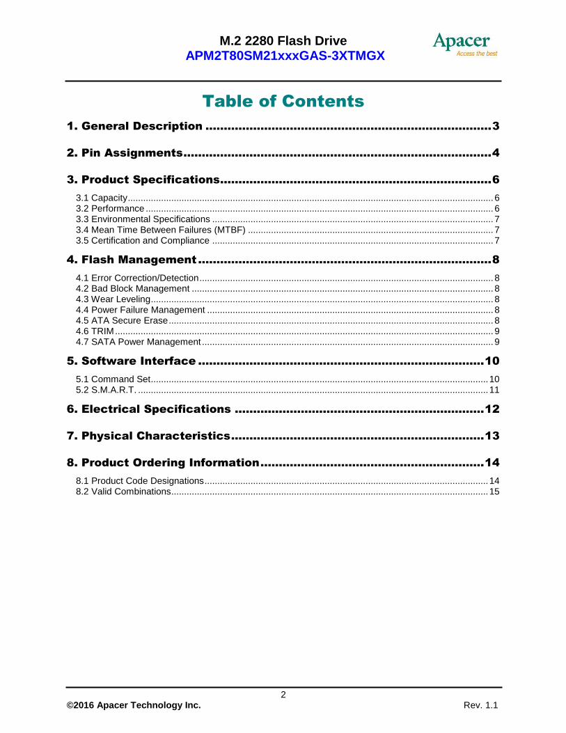
2. Pin Assignments
This connector does not support hot plug capability. There are a total of 75 pins. 12 pin locations are used for mechanical key locations; this allows such a module to plug into both Key B and Key M connectors.
Table of Pin Assignments
Pin Type Description
1 CONFIG_3 Ground (according to M.2 configurations for SSD-SATA definition)
2 3.3V Supply Pin, 3.3V
3 GND Ground
4 3.3V Supply pin, 3.3V
5 No connect No connect
6 Not available No connect (used for other purposes)
7 Not available No connect (used for other purposes)
8 Not available No connect (used for other purposes)
9 No connect No connect
10 DAS/DSS Device Activity Signal/Disable Staggered Spin-up
11 No connect No connect (used for other purposes)
12 (removed for key) Mechanical notch B
13 (removed for key) Mechanical notch B
14 (removed for key) Mechanical notch B
15 (removed for key) Mechanical notch B
16 (removed for key) Mechanical notch B
17 (removed for key) Mechanical notch B
18 (removed for key) Mechanical notch B
19 (removed for key) Mechanical notch B
20 Not available No connect (used for other purposes)
21 CONFIG_0 Ground (according to M.2 configurations for SSD-SATA definition)
22 Not available No connect (used for other purposes)
23 Not available No connect (used for other purposes)
24 Not available No connect (used for other purposes)
25 Not available No connect (used for other purposes)
26 Not available No connect (used for other purposes)
27 GND Ground
28 Not available No connect (used for other purposes)
29 PERn1 Not used
30 Not available No connect (used for other purposes)
31 PERp1 Not used
32 Not available No connect (used for other purposes)
33 GND Ground
34 Not available No connect (used for other purposes)
35 PETn1 Not used
36 Not available No connect (used for other purposes)
Notch B Notch M
Pin1
M.2 2280 Flash Drive APM2T80SM21xxxGAS-3XTMGX
5 © 2016 Apacer Technology Inc. Rev. 1.1
Table of Pin Assignments
Pin Type Description
37 PETp1 Not used
38 DEVSLP Device Sleep, input. If driven high the host is informing the SSD to enter a low power state
39 GND Ground
40 Not available No connect (used for other purposes)
41 SATA-Rx+ Host receiver differential signal pair
42 Not available No connect (used for other purposes)
43 SATA-Rx- Host receiver differential signal pair
44 Not available No connect (used for other purposes)
45 GND Ground
46 Not available No connect (used for other purposes)
47 SATA-Tx- Host transmitter differential pair
48 Not available No connect (used for other purposes)
49 SATA-Tx+ Host transmitter differential pair
50 PERST# Not used
51 GND Ground
52 CLKREQ# Not used
53 REFCLKN Not used
54 PEWAKE# Not used
55 REFCLKP Not used
56 MFG1 Manufacturing pin. Use determined by vendor (no connect on a host)
57 GND Ground
58 MFG2 Manufacturing pin. Use determined by vendor (no connect on a host)
59 (removed for key) Mechanical notch M
60 (removed for key) Mechanical notch M
61 (removed for key) Mechanical notch M
62 (removed for key) Mechanical notch M
63 (removed for key) Mechanical notch M
64 (removed for key) Mechanical notch M
65 (removed for key) Mechanical notch M
66 (removed for key) Mechanical notch M
67 Not available No connect (used for other purposes)
68 SUSCLK Not used
69 CONFIG_1 Ground
70 3.3V Supply pin, 3.3V
71 GND Ground
72 3.3V Supply pin, 3.3V
73 GND Ground
74 3.3V Supply pin, 3.3V
75 CONFIG_2 Ground

M.2 2280 Flash Drive APM2T80SM21xxxGAS-3XTMGX
6 © 2016 Apacer Technology Inc. Rev. 1.1
3. Product Specifications
3.1 Capacity
Capacity specifications of SM210-M280 are available as shown in Table 3-1. It lists the specific capacity and the default numbers of heads, sectors and cylinders for each product line.
Table 3-1 Capacity Specifications
Capacity Total Bytes Cylinders Heads Sectors Max LBA
32 GB 32,017,047,552 16383 16 63 62,533,296
64 GB 64,023,257,088 16383 16 63 125,045,424
128 GB 128,035,676,160 16383 16 63 250,069,680
256 GB 256,060,514,304 16383 16 63 500,118,192
*Display of total bytes varies from file systems, which means not all of the bytes can be used for storage. **Notes: 1 GB = 1,000,000,000 bytes; 1 sector = 512 bytes. LBA count addressed in the table above indicates total user storage capacity and will remain the same throughout the lifespan of the device. However, the total usable capacity of the SSD is most likely to be less than the total physical capacity because a small portion of the capacity is reserved for device maintenance usages.
3.2 Performance
Performance of SM210-M280 is listed below in Table 3-2.
Table 3-2 Performance Specifications
Capacity Performance
32 GB 64 GB 128 GB 256 GB
Sustained read (MB/s) 210 370 500 505
Sustained write (MB/s) 46 90 180 350
Random Read IOPS (4K) 24,000 45,000 76,000 82,000
Random Write IOPS (4K) 11,000 22,000 43,000 79,000
Note: Results may differ from various flash configurations or host system setting IOPS: measured on 8GB span (16777216 sectors Disk Size), 32 Outstanding I/Os (QD=32), Full Random Data pattern, 4KB Align I/Os and test durations 15minutes.
M.2 2280 Flash Drive APM2T80SM21xxxGAS-3XTMGX
7 © 2016 Apacer Technology Inc. Rev. 1.1
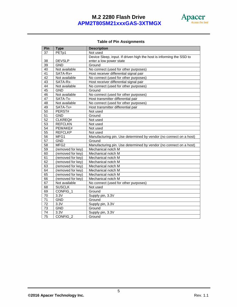
3.3 Environmental Specifications
Environmental specifications of SM210-M280 series follow MIL-STD-810 standards as shown in Table 3-3.
Table 3-3 Environmental Specifications
Item Specifications
Operating temperature 0°C to 70°C (Standard); -40°C to 85°C (Extended)
Non-operating temperature -40°C to 85°C
Vibration (Non-operating) Frequency/Displacement: 20Hz~80Hz/1.52mm Frequency/Acceleration: 80Hz~2000Hz/20G X, Y, Z axis/60mins
shock (Non-operating) 1,500G, 0.5ms
Drop (Non-operating) 80cm free fall, 6 face of each unit
Bending (non-operating) ≧20N, hold 1min/5times
Torque (non-operating) 0.5N-m or ±2.5 deg, hold 1min/5times
ESD (Electrostatic) Passed (at relative temp/humidity: 24°C, 49%RH)
3.4 Mean Time Between Failures (MTBF)
Mean Time Between Failures (MTBF) is predicted based on reliability data for the individual components in SM210-M280. The prediction result for SM210-M280 is more than 1,000,000 hours.
Notes about the MTBF: The MTBF is predicated and calculated based on “Telcordia Technologies Special Report, SR-332, Issue 2” method.
3.5 Certification and Compliance
SM210-M280 complies with the following standards:
CE: EN55022 FCC: CISPR22 BSMI 13438 RoHS Recast
M.2 2280 Flash Drive APM2T80SM21xxxGAS-3XTMGX
8 © 2016 Apacer Technology Inc. Rev. 1.1
4. Flash Management
4.1 Error Correction/Detection
SM210-M280 implements a hardware ECC scheme, based on the BCH algorithm. It can detect and correct up to 72 bits error in 1K bytes.
4.2 Bad Block Management
Current production technology is unable to guarantee total reliability of NAND flash memory array. When a flash memory device leaves factory, it comes with a minimal number of initial bad blocks during production or out-of-factory as there is no currently known technology that produce flash chips free of bad blocks. In addition, bad blocks may develop during program/erase cycles. When host performs program/erase command on a block, bad block may appear in Status Register. Since bad blocks are inevitable, the solution is to keep them in control. Apacer flash devices are programmed with ECC, block mapping technique and S.M.A.R.T to reduce invalidity or error. Once bad blocks are detected, data in those blocks will be transferred to free blocks and error will be corrected by designated algorithms.
4.3 Wear Leveling
Flash memory devices differ from Hard Disk Drives (HDDs) in terms of how blocks are utilized. For HDDs, when a change is made to stored data, like erase or update, the controller mechanism on HDDs will perform overwrites on blocks. Unlike HDDs, flash blocks cannot be overwritten and each P/E cycle wears down the lifespan of blocks gradually. Repeatedly program/erase cycles performed on the same memory cells will eventually cause some blocks to age faster than others. This would bring flash storages to their end of service term sooner. Wear leveling is an important mechanism that level out the wearing of blocks so that the wearing-down of blocks can be almost evenly distributed. This will increase the lifespan of SSDs. Commonly used wear leveling types are Static and Dynamic.
4.4 Power Failure Management
Power Failure Management plays a crucial role when experiencing unstable power supply. Power disruption may occur when users are storing data into the SSD. In this urgent situation, the controller would run multiple write-to-flash cycles to store the metadata for later block rebuilding. This urgent operation requires about several milliseconds to get it done. At the next power up, the firmware will perform a status tracking to retrieve the mapping table and resume previously programmed NAND blocks to check if there is any incompleteness of transmission.
Note: The controller unit of this product model is designed with a DRAM as a write cache for improved performance and data efficiency. Though unlikely to happen in most cases, the data cached in the volatile DRAM might be potentially affected if a sudden power loss takes place before the cached data is flushed into non-volatile NAND flash memory.
4.5 ATA Secure Erase
ATA Secure Erase is an ATA disk purging command currently embedded in most of the storage drives. Defined in ATA specifications, (ATA) Secure Erase is part of Security Feature Set that allows storage drives to erase all user data areas. The erase process usually runs on the firmware level as most of the ATA-based storage media currently in the market are built-in with this command. ATA Secure Erase can securely wipe out the user data in the drive and protects it from malicious attack.

M.2 2280 Flash Drive APM2T80SM21xxxGAS-3XTMGX
9 © 2016 Apacer Technology Inc. Rev. 1.1
4.6 TRIM
TRIM, though in capital letters usually, is a memory computation command rather than an abbreviation. It is mainly a SATA command that enables the operating system to inform the SSD (Solid State Drive) which blocks of previously stored data are no longer valid, due to erases by the host or operating system, such as file deletions or disk formatting. Once notified, SSD will begin the discard of the invalid LBAs and retain more space for itself, in fact, the discarded is no longer recoverable.
When an LBA is replaced by the operating system, as with overwrite of a file, the SSD is informed that the originally occupied LBA is determined as no longer in use or invalid. The SSD will not save those blocks in garbage collected sectors. Noticeably, a file deletion command by host or operating system never actually erases the actual content, rather, just the file is marked as deleted. This issue is even specifically noticeable for flash based memory devices, such as SSDs. In fact, an SSD will keep garbage collecting the invalid, previously occupied LBAs, if it is not informed that these LBAs can be erased. Thus, the SSD would experience a significant performance downfall.
4.7 SATA Power Management
By complying with SATA 6.0 Gb/s specifications, the SSD supports the following SATA power saving modes:
ACTIVE: PHY ready, full power, Tx & Rx operational
PARTIAL: Reduces power, resumes in under 10 µs (microseconds)
SLUMBER: Reduces power, resumes in under 10 ms (milliseconds)
HIPM: Host-Initiated Power Management
DIPM: Device-Initiated Power Management
Device Sleep (DevSleep or DEVSLP): PHY powered down; power consumption ≦ 5 mW; host
assertion time ≦ 10 ms; exit timeout from this state ≦ 20 ms (unless specified otherwise in SATA
Identify Device Log).
Note: The behaviors of power management features would depend on host/device settings.
M.2 2280 Flash Drive APM2T80SM21xxxGAS-3XTMGX
10 © 2016 Apacer Technology Inc. Rev. 1.1
5. Software Interface
5.1 Command Set
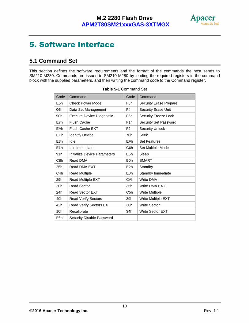
This section defines the software requirements and the format of the commands the host sends to SM210-M280. Commands are issued to SM210-M280 by loading the required registers in the command block with the supplied parameters, and then writing the command code to the Command register.
Table 5-1 Command Set
Code Command Code Command
E5h Check Power Mode F3h Security Erase Prepare
06h Data Set Management F4h Security Erase Unit
90h Execute Device Diagnostic F5h Security Freeze Lock
E7h Flush Cache F1h Security Set Password
EAh Flush Cache EXT F2h Security Unlock
ECh Identify Device 70h Seek
E3h Idle EFh Set Features
E1h Idle Immediate C6h Set Multiple Mode
91h Initialize Device Parameters E6h Sleep
C8h Read DMA B0h SMART
25h Read DMA EXT E2h Standby
C4h Read Multiple E0h Standby Immediate
29h Read Multiple EXT CAh Write DMA
20h Read Sector 35h Write DMA EXT
24h Read Sector EXT C5h Write Multiple
40h Read Verify Sectors 39h Write Multiple EXT
42h Read Verify Sectors EXT 30h Write Sector
10h Recalibrate 34h Write Sector EXT
F6h Security Disable Password
M.2 2280 Flash Drive APM2T80SM21xxxGAS-3XTMGX
11 © 2016 Apacer Technology Inc. Rev. 1.1
5.2 S.M.A.R.T.
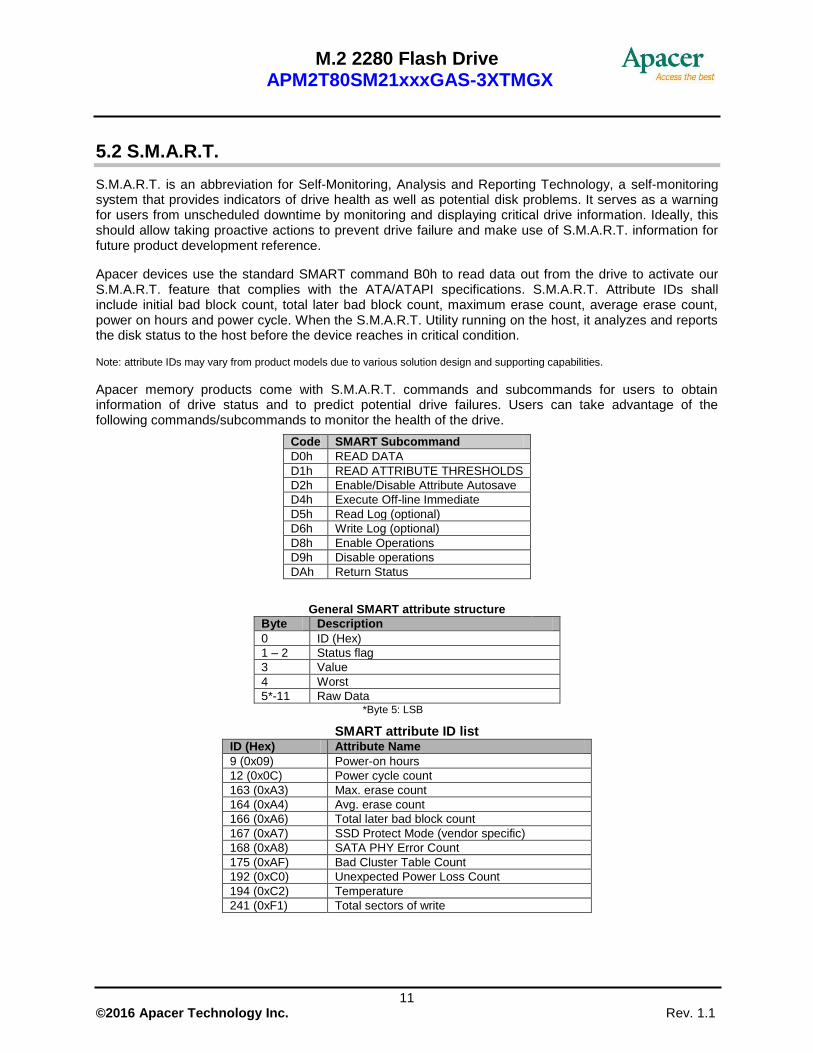
S.M.A.R.T. is an abbreviation for Self-Monitoring, Analysis and Reporting Technology, a self-monitoring system that provides indicators of drive health as well as potential disk problems. It serves as a warning for users from unscheduled downtime by monitoring and displaying critical drive information. Ideally, this should allow taking proactive actions to prevent drive failure and make use of S.M.A.R.T. information for future product development reference.
Apacer devices use the standard SMART command B0h to read data out from the drive to activate our S.M.A.R.T. feature that complies with the ATA/ATAPI specifications. S.M.A.R.T. Attribute IDs shall include initial bad block count, total later bad block count, maximum erase count, average erase count, power on hours and power cycle. When the S.M.A.R.T. Utility running on the host, it analyzes and reports the disk status to the host before the device reaches in critical condition.
Note: attribute IDs may vary from product models due to various solution design and supporting capabilities.
Apacer memory products come with S.M.A.R.T. commands and subcommands for users to obtain information of drive status and to predict potential drive failures. Users can take advantage of the following commands/subcommands to monitor the health of the drive.
Code SMART Subcommand
D0h READ DATA
D1h READ ATTRIBUTE THRESHOLDS
D2h Enable/Disable Attribute Autosave
D4h Execute Off-line Immediate
D5h Read Log (optional)
D6h Write Log (optional)
D8h Enable Operations
D9h Disable operations
DAh Return Status
General SMART attribute structure
Byte Description
0 ID (Hex)
1 – 2 Status flag
3 Value
4 Worst
5*-11 Raw Data *Byte 5: LSB
SMART attribute ID list ID (Hex) Attribute Name
9 (0x09) Power-on hours
12 (0x0C) Power cycle count
163 (0xA3) Max. erase count
164 (0xA4) Avg. erase count
166 (0xA6) Total later bad block count
167 (0xA7) SSD Protect Mode (vendor specific)
168 (0xA8) SATA PHY Error Count
175 (0xAF) Bad Cluster Table Count
192 (0xC0) Unexpected Power Loss Count
194 (0xC2) Temperature
241 (0xF1) Total sectors of write
M.2 2280 Flash Drive APM2T80SM21xxxGAS-3XTMGX
12 © 2016 Apacer Technology Inc. Rev. 1.1
6. Electrical Specifications
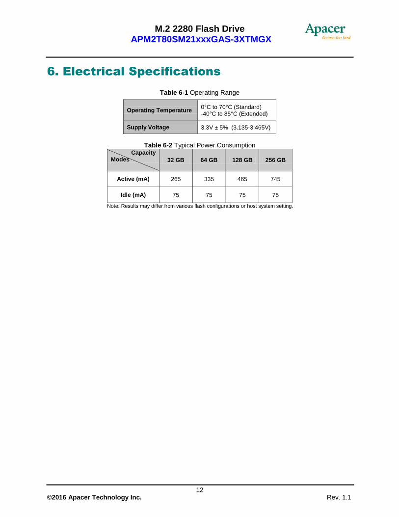
Table 6-1 Operating Range
Operating Temperature 0°C to 70°C (Standard) -40°C to 85°C (Extended)
Supply Voltage 3.3V ± 5% (3.135-3.465V)
Table 6-2 Typical Power Consumption
Capacity Modes 32 GB 64 GB 128 GB 256 GB
Active (mA) 265 335 465 745
Idle (mA) 75 75 75 75
Note: Results may differ from various flash configurations or host system setting.

M.2 2280 Flash Drive APM2T80SM21xxxGAS-3XTMGX
13 © 2016 Apacer Technology Inc. Rev. 1.1
7. Physical Characteristics
M.2 2280 Flash Drive APM2T80SM21xxxGAS-3XTMGX
14 © 2016 Apacer Technology Inc. Rev. 1.1
8. Product Ordering Information
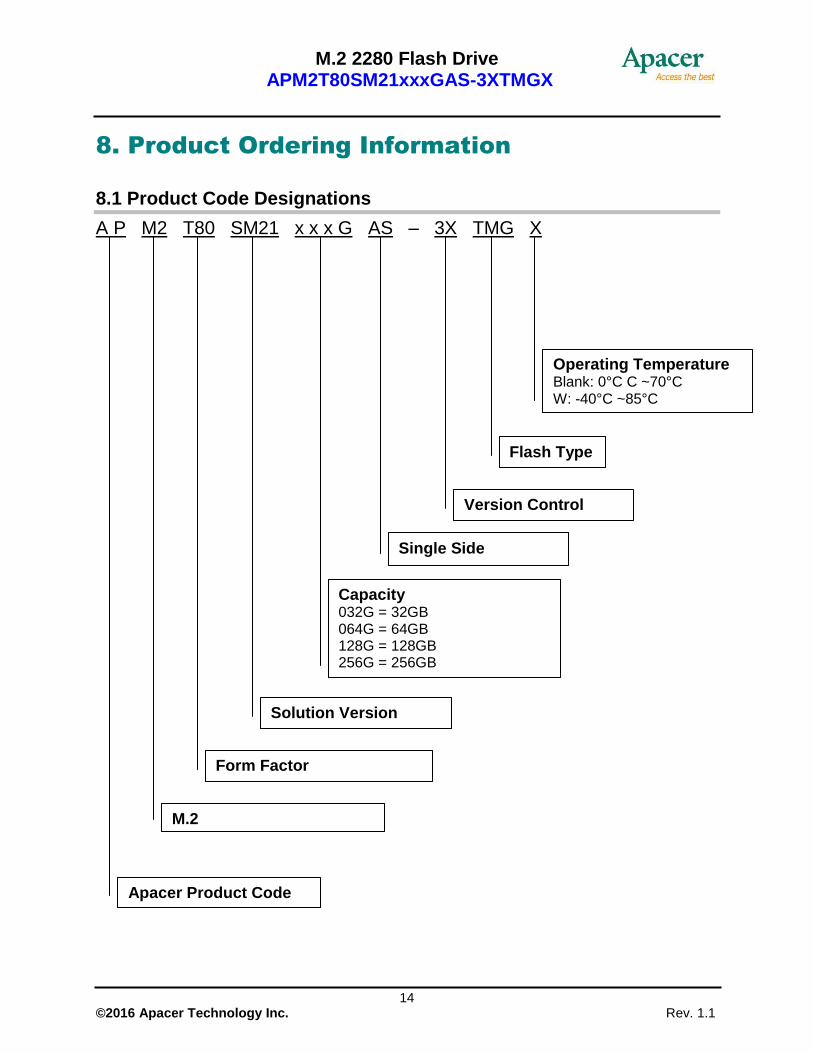
8.1 Product Code Designations
A P M2 T80 SM21 x x x G AS – 3X TMG X
Flash Type
M.2
Apacer Product Code
Form Factor
Solution Version
Capacity 032G = 32GB 064G = 64GB 128G = 128GB 256G = 256GB
Version Control
Operating Temperature Blank: 0°C C ~70°C W: -40°C ~85°C
Single Side

M.2 2280 Flash Drive APM2T80SM21xxxGAS-3XTMGX
15 © 2016 Apacer Technology Inc. Rev. 1.1
8.2 Valid Combinations
8.2.1 Standard Temperature
Capacity No DEVSLP DEVSLP
32GB APM2T80SM21032GAS-3ATMG APM2T80SM21032GAS-3BTMG
64GB APM2T80SM21064GAS-3ATMG APM2T80SM21064GAS-3BTMG
128GB APM2T80SM21128GAS-3ATMG APM2T80SM21128GAS-3BTMG
256GB APM2T80SM21256GAS-3ATMG APM2T80SM21256GAS-3BTMG
8.2.2 Extended Temperature
Capacity No DEVSLP DEVSLP
32GB APM2T80SM21032GAS-3ATMGW APM2T80SM21032GAS-3BTMGW
64GB APM2T80SM21064GAS-3ATMGW APM2T80SM21064GAS-3BTMGW
128GB APM2T80SM21128GAS-3ATMGW APM2T80SM21128GAS-3BTMGW
256GB APM2T80SM21256GAS-3ATMGW APM2T80SM21256GAS-3BTMGW
Note: Valid combinations are those products in mass production or will be in mass production. Consult your Apacer sales representative to confirm availability of valid combinations and to determine availability of new combinations.

M.2 2280 Flash Drive APM2T80SM21xxxGAS-3XTMGX
16 © 2016 Apacer Technology Inc. Rev. 1.1
Revision History
Revision Date Description Remark
1.0 2/3/2016 Official release
1.1 3/7/2016 Revised product ordering information

M.2 2280 Flash Drive APM2T80SM21xxxGAS-3XTMGX
17 © 2016 Apacer Technology Inc. Rev. 1.1
Global Presence
Taiwan (Headquarters)
Apacer Technology Inc.
1F., No.32, Zhongcheng Rd., Tucheng Dist., New Taipei City 236, Taiwan R.O.C. Tel: 886-2-2267-8000 Fax: 886-2-2267-2261 [email protected]
U.S.A.
Apacer Memory America, Inc.
46732 Lakeview Blvd., Fremont, CA 94538 Tel: 1-408-518-8699 Fax: 1-510-249-9568 [email protected]
Japan
Apacer Technology Corp.
5F, Matsura Bldg., Shiba, Minato-Ku Tokyo, 105-0014, Japan Tel: 81-3-5419-2668 Fax: 81-3-5419-0018 [email protected]
Europe
Apacer Technology B.V.
Science Park Eindhoven 5051 5692 EB Son, The Netherlands Tel: 31-40-267-0000 Fax: 31-40-267-0000#6199 [email protected]
China
Apacer Electronic (Shanghai) Co., Ltd
Room D, 22/FL, No.2, Lane 600, JieyunPlaza, Tianshan RD, Shanghai, 200051, China Tel: 86-21-6228-9939 Fax: 86-21-6228-9936 [email protected]
India
Apacer Technologies Pvt Ltd,
Unit No.201, “Brigade Corner”, 7th
Block Jayanagar, Yediyur Circle, Bangalore – 560082, India Tel: 91-80-4152-9061 Fax: 91-80-4170-0215 [email protected]