SerCAN-ARM7 User Manual - EMS Dr. Thomas Wünsche
20
SerCAN-ARM7/RMD User manual Serial/CAN-Gateway
Transcript of SerCAN-ARM7 User Manual - EMS Dr. Thomas Wünsche

SerCANARM7/RMD
User manual
Serial/CANGateway

2 EMS Dr. Thomas Wünsche
SerCANARM7/RMDSerial/CAN Gateway
User manual SerCANARM7/RMD v1.1
Document version: 1.06Documentation date: August 12th, 2015
This document describes the functionality of the SerCANARM7/RMDhardware with firmware version 2.01. Please contact EMS Dr. ThomasWünsche, if you have a module with different firmware.
No part of this document or the software described herein may bereproduced in any form without prior written agreement from EMS Dr.Thomas Wünsche.
For technical assistance please contact:
EMS Dr. Thomas WünscheSonnenhang 3
D85304 Ilmmünster
Tel. +498441490260Fax +49844181860
Our products are continously improved. Due to this fact specifications maybe changed at any time and without announcement.
WARNING: EMS hardware and software may not be used inapplications where damage to life, health or privateproperty may result from failures in or caused bythese components.

SerCANARM7/RMD Serial/CAN Gateway
3EMS Dr. Thomas Wünsche
Content
1 Overview 5
1.1 Features 51.2 General Description 51.3 Ordering Information 5
2 Handling 7
2.1 Connection 72.2 Operation 72.3 Configuration 7
2.3.1 Configuration File 72.3.2 Programming the Device 10
2.4 LED 12
3 Technical Data 13
3.1 Pin Assignment 133.2 Limiting Values 143.3 Nominal Values 14
4 Appendix 15
4.1 Configuration File Example 154.2 Standard CAN Baud Rates 154.4 Instruction for Disposal 184.5 FCC Statement 184.6 CE Conformity 19

4 EMS Dr. Thomas Wünsche
SerCANARM7/RMDSerial/CAN Gateway
THIS PAGE INTENTIONALLY LEFT BLANK

SerCANARM7/RMD Serial/CAN Gateway
5EMS Dr. Thomas Wünsche
1 Overview
1.1 Features
• Connection of a CAN network to a RS232 interface
• Filtering of CAN messages
• CAN bus activity displayed by LED
• Configuration via RS232 connection
• Wiring using a multiway connector
• Available also with low speed CAN transceiver NXP TJA1054
1.2 General description
The Serial/CAN gateway SerCANARM7 connects a CAN network toa RS232 interface. The capability of having different baud rates onthe CAN side as well as on the RS232 side marks the devices aversatile tool for a lot of applications. Bandwith differences betweenCAN and RS232 may be overcome by CAN message filtering.
The device is also available with a low speed physical CAN interfaceusing NXP CAN transceiver TJA1054 (SerCANARM7/RMD/LS).
The device is configured via the RS232 interface. Due to the intuitivestructure of the configuration file in ASCII format, programming andadministration is easy.
1.3 Ordering information
122020220 SerCANARM7/RMD
122020320 SerCANARM7/RMD/LS

6 EMS Dr. Thomas Wünsche
SerCANARM7/RMDSerial/CAN Gateway
THIS PAGE INTENTIONALLY LEFT BLANK

SerCANARM7/RMD Serial/CAN Gateway
7EMS Dr. Thomas Wünsche
2 Handling
2.1 Connection
SerCANARM7 has a multiway connector for flexible wiring of theCAN interface and the power supply. The RS232 interface has astandard SUBD9 male connector and is used for normal operationas well as for the configuration purpose.
The connector assignment of the multiway connector and the RS232interface is described in chapter "3.1 Pin assignment".
2.2 Operation
To start up the gateway just connect the power supply, the devicestarts up automatically. As soon as the automatic diagnostic processis successfully completed the green power LED lites up permanently.
Important note: Ex factory the device offers no configuration andmust be configured before its first run. Configuration instructions forthe gateway are located in chapter "2.3 Configuration".
2.3 Configuration
The gateway configuration process consists of two steps:
• Creating a configuration file
• Loading the configuration into the device
2.3.1 Configuration File
The configuration file is a text file with the extension *.gcf. This fileholds all data needed by the gateway for operation. A completesample configuration is located in chapter "4.1 Configuration FileExample".
The values can either be entered in decimal or hexadecimal notation.Using the hexadecimal notation, the character 'x' has to be entereddirectly before the particular value.

8 EMS Dr. Thomas Wünsche
SerCANARM7/RMDSerial/CAN Gateway
Some parameters are optional. If they are not defined, the gatewayuses default settings.
In the following all parameters are listed and described.
The configuration file can be provided with comments. Commentsare prefaced with the character '#' and they end with the particularline.
Example:# 1st commentkey = value # 2nd comment
The version number indicates the file format of the configuration file.It must be 1 for the actual version.
Example:version=1
For easier identification of the programmed settings, the configrationcan be labeled. The configuration name must not have more than 32characters and must not contain space characters or tabs. If this keyis missing, no name will be assigned.
Example:configname=MyOwnConfig
# comment
version version
configname name assigned to the configuration

SerCANARM7/RMD Serial/CAN Gateway
9EMS Dr. Thomas Wünsche
The CAN bit timing key indicates the speed of the CAN interface.This key is mandatory and is related directly to the CANBTR0register of the used controller LPC2119. This allows most flexiblecustomization of the baudrate settings. The basic CAN clock is48MHz.
Example:# 500 kBaudcanbaudrate = x001c0005
The serial baudrate key is optional. If it is not set, the defaultbaudrate of 57600 baud will be used. A particular value is calculatedwith the following equation:
serialbaudrate = 48000000/(16*BAUDRATE)
The results for some standard values are given below:
9600 Baud : 31219200 Baud : 15638400 Baud : 7857600 Baud : 52115200 Baud : 26
The line settings for the RS232 interface is always 8 data bits, noparity, 1 stop bit (8N1).
The maximum usable baud rate is limited by the serial transceiverchip to 115200 baud.
Please note, that if a serial baud rate is programmed, which is notsupported by the PC used for the configuration process, areconfiguration may become hard to accomplish.
Example:# serial baud rate set to 57600serialbaudrate=52
canbaudrate CAN bit timing
serialbaudrate serial baud rate

10 EMS Dr. Thomas Wünsche
SerCANARM7/RMDSerial/CAN Gateway
This key specifies the period of time in milliseconds, which will passby until the gateway gets bus on again after a bus off condition hasoccured. If this value is not defined, the device remains in bus offstate. If a bus off time of 0 milliseconds is set, the gateway triesimmediately to get bus on again.
Example:busoff=100
This key defines which received CAN messages will be filtered out ornot. Either a particular identifier or a range of identifiers can bespecified. A message which should pass to the RS232 interface musthave a filter rule set. The "sfilter" key relates to 11bit identifiermessages, whereas "xfilter" relates to 29bit identifier.
Example:# A range of 11bit messages starting with id 0 and# ending with id 100h will pass the filter.sfilter=x0x100
# A range of 29bit messages starting with id 100h and# ending with id 1000h will pass the filter.xfilter=x0x10
2.3.2 Programming the Device
SerCANARM7 is programmed by means of the configurationsoftware. It offers the possibility to configure the gateway via theRS232 interface. A "nullmodem" cable has to be used to connect tothe host PC.
The "Program Settings" have to be set to:
• SerCANARM7/RMD
• Program configuration
• a configuration file
bus off bus off behavior
sfilter, xfilter filter key

SerCANARM7/RMD Serial/CAN Gateway
11EMS Dr. Thomas Wünsche
The "Interface Settings" have to be set to:
• Use RS232 interface
• the used PC serial interface port
• 57600 as the serial baudrate used
Within the "Device Settings" the serial number of the SerCANARM7has to be set. The serial number can be found on a label on the rearside of the device.
After all settings are made a click on the "Process" button starts thedownload. Do not remove power from the device until the processhas finished.
Screenshot of the download tool:
12 EMS Dr. Thomas Wünsche
SerCANARM7/RMDSerial/CAN Gateway
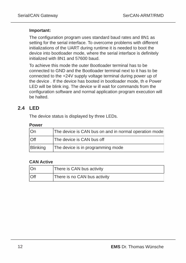
Important:
The configuration program uses standard baud rates and 8N1 assetting for the serial interface. To overcome problems with differentinitializations of the UART during runtime it is needed to boot thedevice into bootloader mode, where the serial interface is definitelyinitialized with 8N1 and 57600 baud.
To achieve this mode the outer Bootloader terminal has to beconnected to GND and the Bootloader terminal next to it has to beconnected to the +24V supply voltage terminal during power up ofthe device . If the device has booted in bootloader mode, th e PowerLED will be blink ing. The device w ill wait for commands from theconfiguration software and normal application program execution willbe halted.
2.4 LED
The device status is displayed by three LEDs.
Power
CAN Active
On The device is CAN bus on and in normal operation mode
Off The device is CAN bus off
Blinking The device is in programming mode
On There is CAN bus activity
Off There is no CAN bus activity

SerCANARM7/RMD Serial/CAN Gateway
13EMS Dr. Thomas Wünsche
3 Technical Data
3.1 Pin Assignment
Pin Assignment multiway connector SerCANARM7/RMD
Pin Assignment multiway connector SerCANARM7/RMD/LS
*internal connected
Pin Signal Description
1 +24V +24 Volt power supply
2 GND Ground*
3 GND Ground*
4 CAN_H CAN high bus line
5 CAN_L CAN low bus line
6 GND Ground*
7 GND Bootloader (connect to Vcc to enter bootloader mode)
8 GND Bootloader (connect to GND to enter bootloader mode)
Pin Signal Description
1 +24V +24 Volt power supply
2 GND Ground*
3 GND Ground*
4 CAN_H CAN high bus line
5 CAN_L CAN low bus line
6 GND Ground*
7 RTH Connected with Pin 4 by a 5k6 resistor andRTH pin of TJA1054 CAN transceiver
8 RTL Connected with Pin 5 by a 5k6 resistor andRTL pin of TJA1054 CAN transceiver

14 EMS Dr. Thomas Wünsche
SerCANARM7/RMDSerial/CAN Gateway
Pin assignment RS232
3.2 Limiting Values
3.3 Nominal Values
Parameter Min. Max. Unit
Storage temperature 20 80 °C
Operating temperature 0 60 °C
Supply voltage 100 30 V
Parameter Min. Max. Unit
Supply voltage 10 30 V
CAN Baudrates 10 1000 kBit/s
Pin Signal Description
1 not connected
2 RxD Receive signal
3 TxD Transmit signal
4 not connected
5 GND Ground
6 not connected
7 RTS not used
8 CTS not used
9 not connected

SerCANARM7/RMD Serial/CAN Gateway
15EMS Dr. Thomas Wünsche
4 Appendix
4.1 Configuration File Example
# Serial/CAN Gateway SerCANARM7 configuration file
# Version number of configuration fileversion=1
# CAN baud rate set to 500kBaudcanbaudrate=x001C0005
# RS232 baud rate set to 57.6 kBaudserialbaudrate=52
# set CAN bus off recovery time to 500msbusoff=500
# filter settings# all 11bit CAN identifier are routedsfilter=x0x7FF
# all 29bit CAN identifiers are routedxfilter=x0x1FFFFFFF
4.2 Standard CAN Baud Rates
baud rate canbaudrate value
1000 kBaud 0x00140005
800 kBaud 0x00160005
500 kBaud 0x001C0005
250 kBaud 0x001C000B
125 kBaud 0x001C0017
100 kBaud 0x001C001D
50 kBaud 0x001C003B
20kBaud 0x001C0095
10 kBaud 0x001C012B

16 EMS Dr. Thomas Wünsche
SerCANARM7/RMDSerial/CAN Gateway
4.3 Serial Protocol Specification
A block oriented protocol is used for message exchange betweenRS232 and CAN.
Format of a data block:
The 'length' byte counts the number of bytes in the fields 'type','length', 'data' and 'checksum'. The two checksum bytes contain thebyte by byte summarization of the fields 'type', 'length' and 'data'.
A number of special characters are used. Reserved characters havevalues less or equal 7.
The following three special characters are used:
In case that a special character has to be transmitted within the datafield, it must be preceeded by an ESCAPE character and the mostsignificant bit of the character has to be set.
Example: Transmission of 0x01Transmitted is 0x02 (ESCAPE) followed by 0x81 (0x01|0x80).
Start Type Length Data Checksum End
1 byte 1 byte 1 byte 'length' 4 bytes 2 bytes 1 byte
Special character Value Description
BEGINOFDATA 0x00 Marks the start of a block
ENDOFDATA 0x01 Marks the end of a block
ESCAPE 0x02 The following character is no specialcharacter. This allows the transmission ofspecial characters in the fields 'type','length', 'data' and 'checksum'.

SerCANARM7/RMD Serial/CAN Gateway
17EMS Dr. Thomas Wünsche
The meaning of the bytes in the 'data' field is indicated by the 'type'field.
A message block of type 'CAN' has the following structure:
A message block of type 'XCAN' has the following structure:
Type Value Description
CAN 0x08 Denotes a CAN message with 11bit identifier
XCAN 0x09 Denotes a CAN message with 29bit identifier
ID RTR Length Data
2 byteslow byte first
1 byte0xFF: RTR frame0x7F: data frame
1 byte data frame: Number ofdata bytes correspondingto 'Length'RTR frame: 0 bytes
ID RTR Length Data
4 byteslow byte first
1 byte0xFF: RTR frame0x7F: data frame
1 byte data frame: Number ofdata bytes correspondingto 'Length'RTR frame: 0 bytes

18 EMS Dr. Thomas Wünsche
SerCANARM7/RMDSerial/CAN Gateway
4.4 Instruction for Disposal
Electronic Equipment Act (WEEE)
EMS is selling its products exclusively to commercial customers. Thisis the reason why all devices are designed for commercial use andhave to be disposed appropriately. In accordance to § 10 para. 2clause 3 Electronic Equipment Act (WEEE) the disposal of EMSproducts is regulated the following way.
The equipment must not be disposed at the public collection points. Inaccordance with the applicable law the disposal has to be done by thecustomer for own account. The same applies to products, which havebeen sold to third parties, if those parties do not take care of adisposal in accordance to the applicable law. As an alternative theproducts can be returned to EMS free of charge.
4.5 FCC Statement
SerCANARM7/RMD Version 1.0 is virtually the same hardware thanCGARM7/RMD Version 1.0. CGARM7/RMD Version 1.0 has beentested and found to comply with the limits for a Class A digital device,pursuant to Part 15 of the FCC Rules. These limits are designed toprovide reasonable protection against harmful interference when theequipment is operated in a commercial environment. This equipmentgenerates, uses, and can radiate radio frequency energy and, if notinstalled and used in accordance with the instruction manual, maycause harmful interference to radio communications. Operation of thisequipment in a residential area is likely to cause harmful interferencein which case the user will be required to correct the interference athis own expense.

SerCANARM7/RMD Serial/CAN Gateway
19EMS Dr. Thomas Wünsche
4.6 CE Conformity