ser Guide EZ SCAN DIGITAL HANDHELD RADIO SCANNER€¦ · EZ SCAN DIGITAL HANDHELD RADIO SCANNER. 2...
76
TRX-1 User Guide All Hazards NOAA’s National Weather Service ® EZ SCAN DIGITAL HANDHELD RADIO SCANNER
Transcript of ser Guide EZ SCAN DIGITAL HANDHELD RADIO SCANNER€¦ · EZ SCAN DIGITAL HANDHELD RADIO SCANNER. 2...
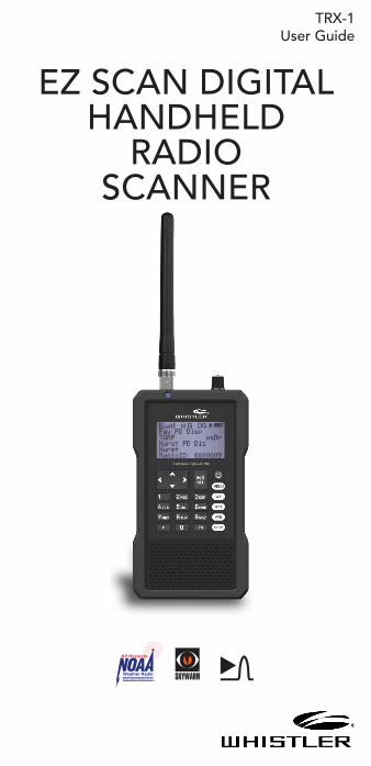
TRX-1User Guide
All Hazards
NOAA’s National Weather Service®
EZ SCAN DIGITALHANDHELD
RADIOSCANNER
2
ContentsIntroduction......................................................................4What is Object Oriented Scanning?...............................4Features............................................................................5Package Contents............................................................5Scanning Legally...............................................................6FCC Statement.................................................................7Setup.................................................................................8Antenna............................................................................8Headphones and Speakers.............................................9Batteries..........................................................................10External Power................................................................11Swivel Belt Clip................................................................11Understanding the Keypad...........................................12Turning On and Set Squelch........................................13Set Bandplan and Clock...............................................14Program Methods..........................................................15Setting Location.............................................................16Power Up Password........................................................18Understanding the Display............................................18psDr Indicators...............................................................20 Display Icons...................................................................21 EZ Scan Library...............................................................22 Maximum Card Size.......................................................23 Installing EZ Scan Software...........................................24Library Updates..............................................................24Preferred Programming from Library..............................25Backup into the first V-Scanner folder...........................26Updating the Library (EZ Scan).....................................26 Library Structure..............................................................27EZ Scan Library Notes.....................................................27 Manual Programming Conventional Frequency...........27Standard Text Entry Method.........................................28Creating Your First New Objects.................................30Essential Conventional Channel Parameters...............30Essential Trunking Talkgroup Parameters....................31Setting up a Trunking System (TSYS) Object.............31Adding a New Trunking System (TSYS).......................32Adding the first Talkgroup............................................33Talkgroup Object (TGRP)...............................................35Importing DMR..............................................................35 Manually Creating/Adding DMR..................................37 Editing Objects Manually..............................................39Alert LED Setting...........................................................41
3
ContentsRecording/Playback.......................................................46IF Output.........................................................................47Internal Clock/Calendar.................................................48Monitoring and Scanning..............................................48Frequency or Talkgroups...............................................48Active Scanlists...............................................................48Enable / Disable Scanlists...............................................49Lock Out Objects...........................................................49Skip Transmission...........................................................49Rename Scanlists...........................................................50Set Priority Objects........................................................50Scanlists and Scan Sets..................................................50Searching........................................................................51 Using Spectrum Sweeper...............................................51 Perform a Service Search................................................52Perform a Limit Search..................................................52To Save Found Frequencies..........................................52 Search Settings...............................................................53Spectrum Sweeper Settings..........................................53Service Search Settings..................................................53Limit Search Settings......................................................53Saving Found CTCSS or DCS Codes...........................54Weather Monitoring.......................................................55Program FIPS Codes......................................................55Entering SAME Location and Event Codes..................56SAME Standby Modes...................................................57Weather Priority..............................................................58SKYWARN® ...................................................................58Using V-Scanner Storage...............................................59Configuring Settings......................................................59 Using EZ Scan Software to Update Scanner.................62DSP Firmware Updates..................................................62Updating the Library (PC)..............................................62 Maintenance ..................................................................63Birdie Frequencies.........................................................63Troubleshooting/Error Messages..................................64Library Copyright Notice...............................................67Specifications .................................................................68Frequency Coverage.....................................................69Consumer Warranty.......................................................70Service Under Warranty.................................................71Service Out-of-Warranty................................................72
4
IntroductionScanning technology has changed dramatically over the years. A scanner with Object Oriented User Interface is designed to help the hobbyist build a collection of channels to scan:
• Start small and expand
• Organize channels and talkgroups
• Remove unwanted channels and talkgroups
What is Object Oriented Scanning?
Programming scanning receivers can be challenging, but object-oriented programming simplifies the process by using common conventions for scanning concepts that have common characteristics.
A Scannable Object is any defined item that can be scanned or monitored, including:
• Conventional, non-trunked radio frequencies
• Talkgroups used on a trunked radio system
• Radio services
• Defined searches
Because scannable objects are defined by the same basic elements, the Object Oriented User Interface (OOUI) is designed to simplify scanning by managing all scannable objects similarly. When you learn how to program one type of object, you can program other types of scannable objects as well.
5
Features• Functional keypad and backlit LCD display
• USA/Canada Radio Reference database on SD Card
• Quick Location based Programming (City, Zip, County)
• Detects and masks encrypted voice audio
• Decodes Radio ID/Talkgroup ID data
• Upgradeable CPU Firmware, DSP Firmware and Database Library
• USB Interface 2.0 or earlier
• DMR/MotoTRBO™ Tier II
• Improved P25 Functionality (Phase II, X2-TDMA)
• PC Software to customize your settings
• Signal Strength Meter
• 200 Scanlists
• Weather Radio Functions
• Multi–system Trunking
• Spectrum Sweeper
• Headphone Jack
• Programmable Alert LED
• Programmable Audio Alarms
• V-Scanner II Storage System
• Audio Recording
• Built-in Clock/Calendar
• Built-in Services Searches
• Built-in Discriminator output
Package Contents• Handheld Scanner
• Antenna
• USB Cable
• Micro SD Card (Installed in the Scanner)
• PC Software included on SD Card
• Swivel Belt Clip
• Protective Case
• User Guide
• Quick Start Guide
6
Scanning LegallyYour scanner covers frequencies used by many different groups including police and fire departments, ambulance services, government agencies, private companies, amateur radio services, military operations, pager services, and wireline (telephone and telegraph) service providers. It is legal to listen to almost every transmission your scanner can receive. However, there are some transmissions you should never intentionally listen to.
These include:
• Telephone conversations (cellular, cordless, or other means of private telephone signal transmission)
• Paging transmissions
• Any intentionally decoded scrambled or encrypted transmissions
According to the Electronic Communications Privacy Act (ECPA), you are subject to fines and possible imprisonment for intentionally listening to, using, or divulging the contents of such a transmission unless you have the consent of a party to the communication (unless such activity is otherwise illegal). This scanner has been designed to prevent reception of illegal transmissions. This is done to comply with the legal requirement that scanners be manufactured so as to not be easily modifiable to pick up those transmissions.
Do not open your scanner’s case to make any modifications that could allow it to pick up transmissions that are illegal to monitor. Doing so could subject you to legal penalties. We encourage responsible, legal scanner use. In some areas, mobile use of this scanner is unlawful or requires a permit. Check the laws in your area. It is also illegal in many areas to interfere with the duties of public safety officials by traveling to the scene of an incident without authorization.
Even where not permitted, mobile use of a scanner is typically permitted if you are a licensed Amateur Radio operator capable of emergency radio communications. If interested, see www.arrl.org for information on becoming a ham radio operator.
7
FCC StatementThis equipment has been tested and found to comply with the limits for a scanning receiver, pursuant to Part 15 of the FCC Rules. These limits are designed to provide reasonable protection against harmful interference in a residential installation. This equipment generates, uses and can radiate radio frequency energy and, if not installed and used in accordance with the instructions, may cause harmful interference to radio communications. However, there is no guarantee that interference will not occur in a particular installation. If this equipment does cause harmful interference to radio or television reception, which can be determined by turning the equipment off and on, the user is encouraged to try to correct the interference by one or more of the following measures:
• Reorient or relocate the receiving antenna.
• Increase the separation between the equipment and receiver.
• Connect the equipment into an outlet on a circuit different from that to which the receiver is connected.
This device complies with Part 15 of the FCC Rules. Operation is subject to the following two conditions:
(1)This device may not cause harmful interference.
(2)This device must accept any interference received, including interference that may cause undesired operation.
WARNING: Changes or modifications to this unit not expressly approved by the party responsible for compliance could void the user’s authority to operate the equipment.
Shielded cables must be used with this unit to ensure compliance with the Class B FCC limits.
8
Setup
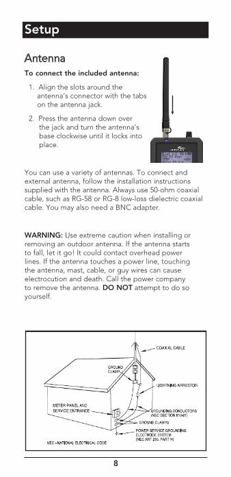
AntennaTo connect the included antenna:
1. Align the slots around the antenna’s connector with the tabs on the antenna jack.
2. Press the antenna down over the jack and turn the antenna’s base clockwise until it locks into place.
You can use a variety of antennas. To connect and external antenna, follow the installation instructions supplied with the antenna. Always use 50-ohm coaxial cable, such as RG-58 or RG-8 low-loss dielectric coaxial cable. You may also need a BNC adapter.
WARNING: Use extreme caution when installing or removing an outdoor antenna. If the antenna starts to fall, let it go! It could contact overhead power lines. If the antenna touches a power line, touching the antenna, mast, cable, or guy wires can cause electrocution and death. Call the power company to remove the antenna. DO NOT attempt to do so yourself.
9
WARNING: Outdoor antennas must be properly grounded to prevent static buildup and lightning damage. Article 810 of the National Electrical Code, ANSI/NFPA 70, provides information about proper grounding of the antenna mast, connection of coaxial cable to an lightning arrestor, size of grounding conductors, location of the lightning arrestor and connection of grounding conductors to grounding electrodes.
Disconnect your radio from the outdoor antenna during electrical storm activity to prevent damage.
Headphones and SpeakersYou can plug headphones (not supplied) or an amplified speaker (not supplied) with a 1/8 inch (3.5mm) stereo mini-plug in the headphone jack on top of your scanner. This automatically disconnects the internal speaker.
NOTE: Use an amplified speaker; a non-amplified speaker may not provide sufficient volume for comfortable listening.
Listening Safely
To protect your hearing, follow these guidelines when you use headphones:
• Set the volume to zero before putting on headphones. With the headphones on, adjust the volume to a comfortable level.
• Avoid increasing the volume after you set it. Over time, your sensitivity to a volume level decreases, so volume levels that do not cause discomfort might damage your hearing. Avoid or limit listening at high-volume levels. Prolonged exposure to high- volume levels can cause permanent hearing loss.
• Wearing headphones while operating a motor vehicle or riding a bicycle can create a traffic hazard and is illegal in most areas. Even though some headphones let you hear some outside sounds when listening at normal volume levels, they still can present a traffic hazard. Exercise extreme caution!
10
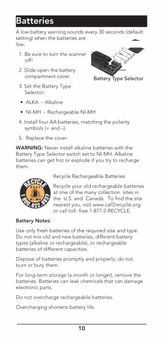
BatteriesA low battery warning sounds every 30 seconds (default setting) when the batteries are low.
1. Be sure to turn the scanner off!
2. Slide open the battery compartment cover.
3. Set the Battery Type Selector:
• ALKA − Alkaline
• NI-MH − Rechargeable NI-MH
4. Install four AA batteries, matching the polarity symbols (+ and –).
5. Replace the cover.
WARNING: Never install alkaline batteries with the Battery Type Selector switch set to NI-MH. Alkaline batteries can get hot or explode if you try to recharge them.
Recycle Rechargeable Batteries
Recycle your old rechargeable batteries at one of the many collection sites in the U.S. and Canada. To find the site nearest you, visit www.call2recycle.org or call toll- free 1-877-2-RECYCLE.
Battery Notes:
Use only fresh batteries of the required size and type. Do not mix old and new batteries, different battery types (alkaline or rechargeable), or rechargeable batteries of different capacities.
Dispose of batteries promptly and properly; do not burn or bury them.
For long-term storage (a month or longer), remove the batteries. Batteries can leak chemicals that can damage electronic parts.
Do not overcharge rechargeable batteries.
Overcharging shortens battery life.
Battery Type Selector
11
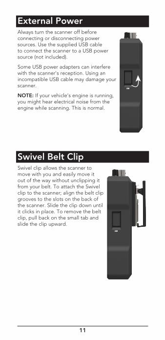
External PowerAlways turn the scanner off before connecting or disconnecting power sources. Use the supplied USB cable to connect the scanner to a USB power source (not included).
Some USB power adapters can interfere with the scanner's reception. Using an incompatible USB cable may damage your scanner.
NOTE: If your vehicle’s engine is running, you might hear electrical noise from the engine while scanning. This is normal.
Swivel Belt ClipSwivel clip allows the scanner to move with you and easily move it out of the way without unclipping it from your belt. To attach the Swivel clip to the scanner; align the belt clip grooves to the slots on the back of the scanner. Slide the clip down until it clicks in place. To remove the belt clip, pull back on the small tab and slide the clip upward.
12
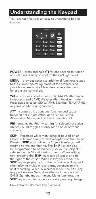
Understanding the KeypadYour scanner features an easy-to understand backlit keypad.
POWER – press and hold for one second to turn on and off. Press briefly to confirm the backlight level.
MENU – provides access to additional functions related to the current operating mode of the scanner, and provides access to the Main Menu where the main functions are controlled.
WX – provides instant access to NOAA Weather Radio broadcasts and SAME Weather Alert Receiver mode. Press twice to select SKYWARN® Scanlist. (SKYWARN® requires one-time programming)
ATT – controls the attenuator function and cycles between Per Object Attenuation Mode, Global Attenuation Mode, and Global Attenuation On.
PRI – toggles the Priority setting for selected or active object, Fn PRI toggles Priority Mode on or off while scanning.
SKIP – if pressed while monitoring or paused on an Object will temporarily disable reception on the Object. Pressing SKIP again while the Object is selected will resume normal monitoring. The SKIP key can also be programmed to permanently lockout an object if selected in the Global Settings menu. When editing text, pressing the SKIP key clears all text at and to the right of the cursor. When in Playback mode, the SKIP key stops playback of the current recording, and when playing multiple recordings, advances to the next recording. When in Weather mode, the SKIP key toggles between Normal weather radio mode and SAME Standby mode. In many Menu functions, the SKIP key is used to cancel or abort a pending change.
Fn – activates alternate key functions.
13
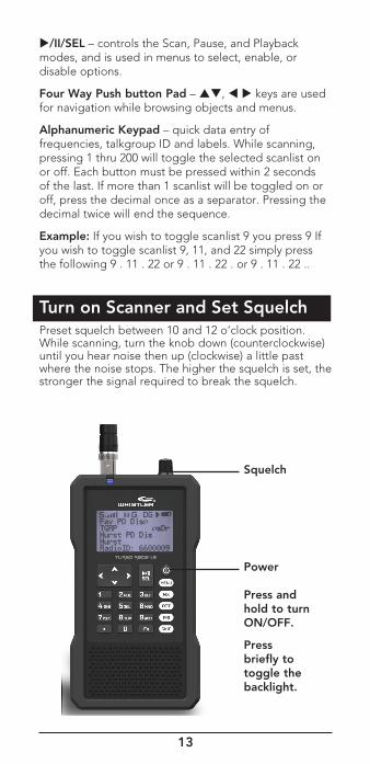
Squelch
Power
Press and hold to turn ON/OFF.
Press briefly to toggle the backlight.
/II/SEL – controls the Scan, Pause, and Playback modes, and is used in menus to select, enable, or disable options.
Four Way Push button Pad – , keys are used for navigation while browsing objects and menus.
Alphanumeric Keypad – quick data entry of frequencies, talkgroup ID and labels. While scanning, pressing 1 thru 200 will toggle the selected scanlist on or off. Each button must be pressed within 2 seconds of the last. If more than 1 scanlist will be toggled on or off, press the decimal once as a separator. Pressing the decimal twice will end the sequence.
Example: If you wish to toggle scanlist 9 you press 9 If you wish to toggle scanlist 9, 11, and 22 simply press the following 9 . 11 . 22 or 9 . 11 . 22 . or 9 . 11 . 22 ..
Turn on Scanner and Set SquelchPreset squelch between 10 and 12 o’clock position. While scanning, turn the knob down (counterclockwise) until you hear noise then up (clockwise) a little past where the noise stops. The higher the squelch is set, the stronger the signal required to break the squelch.
14
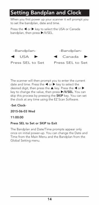
Setting Bandplan and ClockWhen you first power up your scanner it will prompt you to set the bandplan, date and time.
Press the or key to select the USA or Canada bandplan, then press /II/SEL.
-Bandplan- -Bandplan-
USA Canada
Press SEL to Set Press SEL to Set
The scanner will then prompt you to enter the current date and time. Press the or key to select the desired digit, then press the key. Press the or key to change the value, then press /II/SEL. You can skip this process by pressing the SKIP key. You can set the clock at any time using the EZ Scan Software.
-Set Clock-
2015-06-03 Wed
11:00:00
Press SEL to Set or SKIP to Exit
The Bandplan and Date/Time prompts appear only once on initial power-up. You can change the Date and Time from the Main Menu and the Bandplan from the Global Setting menu.
15
Program MethodsThere are two methods to program your scanner. To get started quickly, you can use “Set Location.” The set location method stores objects in your area automatically and puts them in Scanlists 151 and higher. These Scanlists are already named, “Multi Dispatch,” “Law Tac,” “Interop” “Fire Talk,” and so forth. This method gets you scanning in minutes, but you cannot monitor a single police or a single fire department – they will all be together in the same Scanlist. Also, if you use set location, and wish to add a new location, be sure to “Clear Channels” to erase old objects before storing the new location. If you store more than one ZIP code, the scanner will spend a great deal of time searching for objects that are out of range. That will cause the scanner to miss some local transmissions you want to hear.
Although it takes longer, experienced users will want to program Scanlists on their own using the “Preferred” method. Use “Browse Library” to select your state and county and look for agencies of interest. Check the boxes of objects you wish to import, select the Scanlist you want to put them in and perform the import (see Preferred Programming). Once you save objects to a Scanlist, rename the Scanlist so you don’t forget what you stored there. Then import more objects into a different Scanlist and rename that one. In this way, you can create Scanlists such as Bethel Police, Hurst Police, Bethel Fire, Shenango EMS, etc. Individual scanlists allow you to decide exactly what you want to scan.
16
Setting LocationYour scanner can select services to scan based on your location. Press MENU and scroll to “Set Location” and press the key.
You can specify your location by City, County or ZIP Code. Scroll to the desired method and press the key. If you select City or County, the scanner will prompt you for your State. Use the or key to select the first letter of your State, then press the /II/SEL key. Scroll to your state and press the key. Use the or key to select the first letter of your City or county, then press the /II/SEL key. Scroll to your City or County, then press the key.
Select County:
First letter: A
SEL = Done
If you select ZIP Code, the scanner will prompt you to enter your five-digit ZIP Code. Use the or key to adjust each digit, then use the or key to select each digit. When you are done, press the /II/SEL key.
ZIP Code
00000
moves cursor
SEL=OK MENU=BACK
NOTE: Although you can program multiple locations, to get maximum scanner performance its best to program only 1 location or ZIP code. Scanning multiple locations will cause missed transmissions due to the scanner searching for out of range frequencies.
You can accept a preselected set of Default Types for your location, or you can specify Custom Types (see next section). To select the Default Service Types, press the key, then the /II/SEL key to import the Default Set of Service Types for that City or County. Wait for the Import process to end, then press the /II/SEL.
-Confirmation-
Really do import operation?
SEL=Yes SKIP=No
To perform additional imports, press the /II/SEL key and proceed as before. Press the SKIP key to return to the Main Menu.
17
To select Custom Types, press the key. Scroll through the list of Services and press the /II/SEL key to select Services you wish to import. A check mark appears next to each selected Service.
Services:
SEL = Toggle
Multi Dispatch
Law Dispatch
Fire Dispatch
EMS Dispatch
When you are done, press the key, then the / II/SEL key to import the selected services. Press the SKIP key to return to the Service list without importing. To perform additional imports, press the /II/SEL key and wait for import process to end. Press the SKIP key to return to the Main Menu.
Services selected through Set Location are automatically assigned to Scanlists beginning at number 151; each selected Service is assigned to a separate Scanlist, which is given the name of the service.
These Scanlists are automatically selected for Scanning. You can select or deselect Scanlists as desired through the Scanlist item on the Main Menu.
NOTE: Press or MENU to return to main menu.
To clear all data from the current Folder on the Set Location menu scroll to Clear Channels and press the key. On the Confirmation screen press the /II/SEL key to clear the data, or press the SKIP key to return to the Set Location menu without clearing.
-Confirmation-
Really clear ALL programmed data from the current folder?
SEL=Yes, SKIP=No
NOTE: The Clear Channels function erases all of your current scanning data; all Scanlists in this Folder will be empty. Use this function carefully, as it cannot be undone. Does not affect V-Scanner folders content.
18
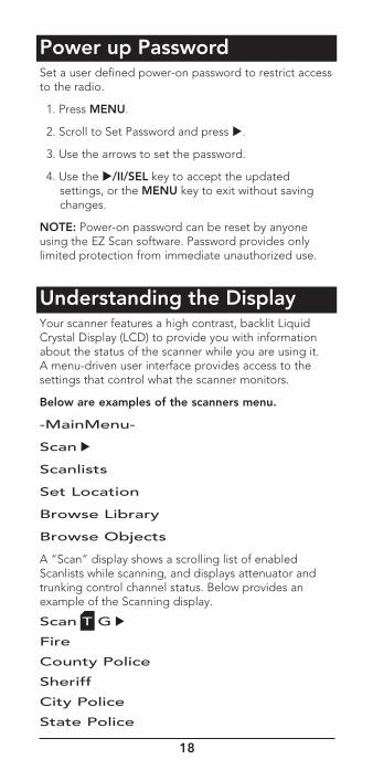
Power up Password Set a user defined power-on password to restrict access to the radio.
1. Press MENU.
2. Scroll to Set Password and press .
3. Use the arrows to set the password.
4. Use the /II/SEL key to accept the updated settings, or the MENU key to exit without saving changes.
NOTE: Power-on password can be reset by anyone using the EZ Scan software. Password provides only limited protection from immediate unauthorized use.
Understanding the DisplayYour scanner features a high contrast, backlit Liquid Crystal Display (LCD) to provide you with information about the status of the scanner while you are using it. A menu-driven user interface provides access to the settings that control what the scanner monitors.
Below are examples of the scanners menu.
-MainMenu-
Scan
Scanlists
Set Location
Browse Library
Browse Objects
A “Scan” display shows a scrolling list of enabled Scanlists while scanning, and displays attenuator and trunking control channel status. Below provides an example of the Scanning display.
Scan T G
Fire
County Police
Sheriff
City Police
State Police
19
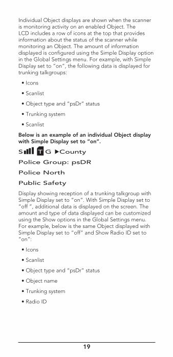
Individual Object displays are shown when the scanner is monitoring activity on an enabled Object. The LCD includes a row of icons at the top that provides information about the status of the scanner while monitoring an Object. The amount of information displayed is configured using the Simple Display option in the Global Settings menu. For example, with Simple Display set to “on”, the following data is displayed for trunking talkgroups:
• Icons
• Scanlist
• Object type and “psDr” status
• Trunking system
• Scanlist
Below is an example of an individual Object display with Simple Display set to “on”.
S T G County
Police Group: psDR
Police North
Public Safety
Display showing reception of a trunking talkgroup with Simple Display set to “on”. With Simple Display set to “off ”, additional data is displayed on the screen. The amount and type of data displayed can be customized using the Show options in the Global Settings menu. For example, below is the same Object displayed with Simple Display set to “off” and Show Radio ID set to “on”:
• Icons
• Scanlist
• Object type and “psDr” status
• Object name
• Trunking system
• Radio ID
20
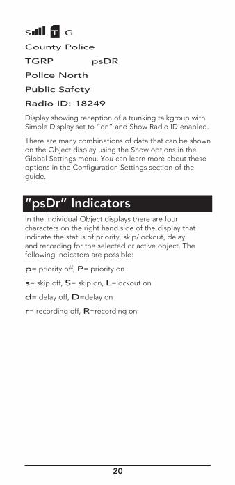
S T G
County Police
TGRP psDR
Police North
Public Safety
Radio ID: 18249
Display showing reception of a trunking talkgroup with Simple Display set to “on” and Show Radio ID enabled.
There are many combinations of data that can be shown on the Object display using the Show options in the Global Settings menu. You can learn more about these options in the Configuration Settings section of the guide.
“psDr” IndicatorsIn the Individual Object displays there are four characters on the right hand side of the display that indicate the status of priority, skip/lockout, delay and recording for the selected or active object. The following indicators are possible:
p= priority off, P= priority on
s= skip off, S= skip on, L=lockout on
d= delay off, D=delay on
r= recording off, R=recording on
21
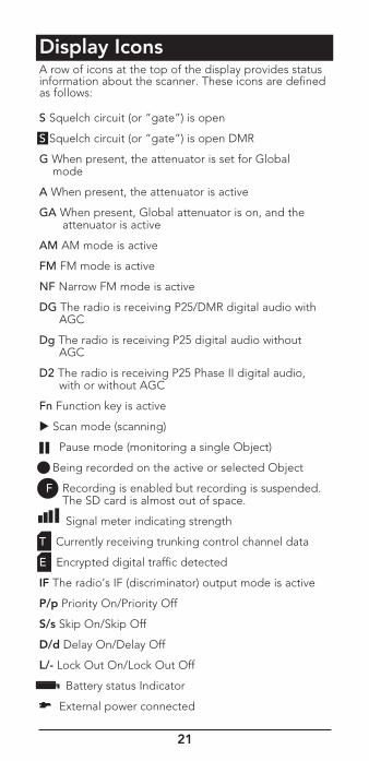
Display IconsA row of icons at the top of the display provides status information about the scanner. These icons are defined as follows:
S Squelch circuit (or “gate”) is open
S Squelch circuit (or “gate”) is open DMR
G When present, the attenuator is set for Global mode
A When present, the attenuator is active
GA When present, Global attenuator is on, and the attenuator is active
AM AM mode is active
FM FM mode is active
NF Narrow FM mode is active
DG The radio is receiving P25/DMR digital audio with AGC
Dg The radio is receiving P25 digital audio without AGC
D2 The radio is receiving P25 Phase II digital audio, with or without AGC
Fn Function key is active
Scan mode (scanning)
Pause mode (monitoring a single Object)
Being recorded on the active or selected Object
F Recording is enabled but recording is suspended. The SD card is almost out of space.
Signal meter indicating strength
T Currently receiving trunking control channel data
E Encrypted digital traffic detected
IF The radio’s IF (discriminator) output mode is active
P/p Priority On/Priority Off
S/s Skip On/Skip Off
D/d Delay On/Delay Off
L/- Lock Out On/Lock Out Off
Battery status Indicator
External power connected
22
EZ Scan LibraryYour scanner comes with an installed Micro SD card that contains the entire USA/Canadian Radio Reference database as well as the EZ Scan software.
NOTE: Make a copy of the EZ Scan software files in case the SD card is lost or damaged.
To remove the Micro SD card from the scanner:
WARNING: To prevent corrupted data on the Micro SD Card, always turn the scanner off using the front panel power key before opening the battery compartment cover.
1. Turn off scanner, unplug external power, and remove the batteries.
2. Press and release the Micro SD card.
3. To reinsert the Micro SD card, with the label facing the front of the radio press it in until it clicks in place.
NOTE: Always use the EZ Scan software “Prepare Scanner Memory/SD Card For Use” option under the “Scanner/ SD Card”menu to format the Micro SD Card if the card is not performing as expected or if the scanner does not power up with the Micro SD Card.
The Micro SD card comes formatted for the standard FAT file system with a cluster size of 32k.
To format additional cards (2GB or smaller), use only the EZ Scan software to format the Micro SD card.
• Format using the FAT file system with 32k clusters.
• If you use Micro SD cards larger than 2GB, format using FAT32 with 32k clusters.
• Formatting the Micro SD card for other file system types may cause EZ Scan to malfunction.
Connecting the scanner to a computer with the supplied USB cable allows you to access the card with the EZ Scan software and update the Library, edit the configuration and stored objects, optimize the card, and reformat the card if necessary. You can also connect the SD Card to an external reader, which may provide faster data transfer rates when compared to accessing the card while it is in the radio.
23
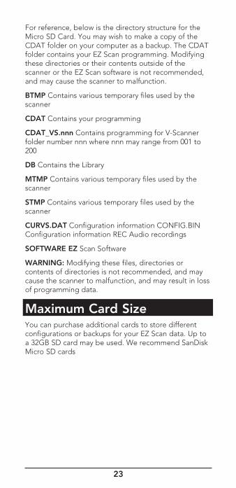
For reference, below is the directory structure for the Micro SD Card. You may wish to make a copy of the CDAT folder on your computer as a backup. The CDAT folder contains your EZ Scan programming. Modifying these directories or their contents outside of the scanner or the EZ Scan software is not recommended, and may cause the scanner to malfunction.
BTMP Contains various temporary files used by the scanner
CDAT Contains your programming
CDAT_VS.nnn Contains programming for V-Scanner folder number nnn where nnn may range from 001 to 200
DB Contains the Library
MTMP Contains various temporary files used by the scanner
STMP Contains various temporary files used by the scanner
CURVS.DAT Configuration information CONFIG.BIN Configuration information REC Audio recordings
SOFTWARE EZ Scan Software
WARNING: Modifying these files, directories or contents of directories is not recommended, and may cause the scanner to malfunction, and may result in loss of programming data.
Maximum Card SizeYou can purchase additional cards to store different configurations or backups for your EZ Scan data. Up to a 32GB SD card may be used. We recommend SanDisk Micro SD cards
24
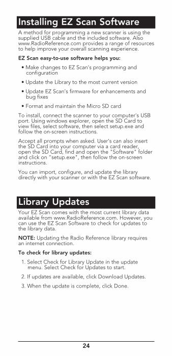
Installing EZ Scan SoftwareA method for programming a new scanner is using the supplied USB cable and the included software. Also www.RadioReference.com provides a range of resources to help improve your overall scanning experience.
EZ Scan easy-to-use software helps you:
• Make changes to EZ Scan’s programming and configuration
• Update the Library to the most current version
• Update EZ Scan’s firmware for enhancements and bug fixes
• Format and maintain the Micro SD card
To install, connect the scanner to your computer's USB port. Using windows explorer, open the SD Card to view files, select software, then select setup.exe and follow the on-screen instructions.
Accept all prompts when asked. User's can also insert the SD Card into your computer via a card reader, open the SD Card, find and open the "Software" folder and click on "setup.exe", then follow the on-screen instructions.
You can import, configure, and update the library directly with your scanner or with the EZ Scan software.
Library UpdatesYour EZ Scan comes with the most current library data available from www.RadioReference.com. However, you can use the EZ Scan Software to check for updates to the library data.
NOTE: Updating the Radio Reference library requires an internet connection.
To check for library updates:
1. Select Check for Library Update in the update menu. Select Check for Updates to start.
2. If updates are available, click Download Updates.
3. When the update is complete, click Done.
25
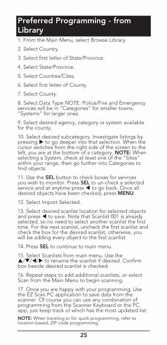
Preferred Programming - from Library1. From the Main Menu, select Browse Library.
2. Select Country.
3. Select first letter of State/Province.
4. Select State/Province.
5. Select Counties/Cites.
6. Select first letter of County.
7. Select County.
8. Select Data Type NOTE: Police/Fire and Emergency services will be in “Categories” for smaller towns, “Systems” for larger ones.
9. Select desired agency, category or system available for the county.
10. Select desired subcategory. Investigate listings by pressing to go deeper into that selection. When the cursor switches from the right side of the screen to the left, you are at the bottom of a category. NOTE: When selecting a System, check at least one of the “Sites” within your range, then go further into Categories to find objects.
11. Use the SEL button to check boxes for services you wish to monitor. Press SEL to un-check a selected service and at anytime press to go back. Once all desired objects have been checked, press MENU.
12. Select Import Selected.
13. Select desired scanlist location for selected objects and press to save. Note that Scanlist 001 is already selected, so no need to select another scanlist the first time. For the next scanlist, uncheck the first scanlist and check the box for the desired scanlist, otherwise, you will be adding every object to the first scanlist.
14. Press SEL to continue to main menu.
15. Select Scanlists from main menu. Use the /// to rename the scanlist if desired. Confirm box beside desired scanlist is checked.
16. Repeat steps to add additional scanlists, or select Scan from the Main Menu to begin scanning.
17. Once you are happy with your programming, Use the EZ Scan PC application to save data from the scanner. Of course you can use any combination of programming from the Scanner Keyboard or the PC app, just keep track of which has the most updated list.NOTE: When traveling or for quick programming, refer to location based, ZIP code programming.
26
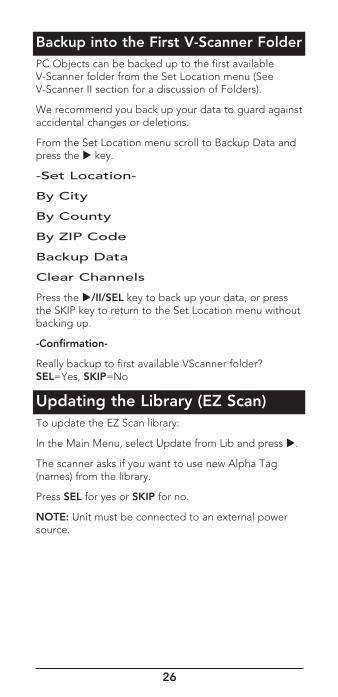
Backup into the First V-Scanner FolderPC Objects can be backed up to the first available V-Scanner folder from the Set Location menu (See V-Scanner II section for a discussion of Folders).
We recommend you back up your data to guard against accidental changes or deletions.
From the Set Location menu scroll to Backup Data and press the key.
-Set Location-
By City
By County
By ZIP Code
Backup Data
Clear Channels
Press the /II/SEL key to back up your data, or press the SKIP key to return to the Set Location menu without backing up.
-Confirmation-
Really backup to first available VScanner folder? SEL=Yes, SKIP=No
Updating the Library (EZ Scan)To update the EZ Scan library:
In the Main Menu, select Update from Lib and press .
The scanner asks if you want to use new Alpha Tag (names) from the library.
Press SEL for yes or SKIP for no.
NOTE: Unit must be connected to an external power source.
27
Library StructureEach state contains three data types:
• Agencies – Statewide conventional frequencies
• Counties/Cities – County or independent city
• Systems – Statewide trunked systems, control frequencies (sites) and talkgroups.
Each county contains three data types:
• Agencies – Local conventional frequencies
• Categories – Public service conventional frequencies
• Systems – Public service trunked systems, control frequencies (sites) and talkgroups.
NOTE: Not all states have a statewide trunked radio system.
WARNING: Modifying these directories or their contents is not recommended and may cause EZ Scan to malfunction.
EZ Scan Library Notes • A “D” indicates that the item uses an unsupported digital modulation and cannot be monitored.
• An “S” indicates a trunked system that is not supported by the scanner.
A gray box () indicates that some frequencies in a grouping are selected, but not all.
Manual Programming - EnterConventional Frequency 1. Press MENU to access Main Menu.
2. Scroll to and select “Program Menu” then “Add Conv Freq”.
3. Simply write over the existing frequency or press “SKIP” to clear. Using the alphanumeric keypad or the , buttons, enter the desired conventional frequency. Press SEL when finished.
4. Scroll to “Save Changes” then press SEL.
5. Press MENU returns to Main menu.
28
Standard Text Entry MethodYour scanner features a high-contrast, backlit alphanumeric display that provides constant feedback about what the radio is doing while scanning and monitoring your “Scannable Objects”. To get the most out of your scanner and this display, you will want to name your objects as you program them into the radio.
This allows for easy identification of active objects while the radio is scanning.
Your scanner uses a simple text entry method that allows entry of all uppercase and lowercase letters of the alphabet, numbers, and punctuation symbols.
Entering and Editing Alphanumeric Information
A Standard Text Entry Method is used for entering alphanumeric information into the radio. This method allows easy access to each letter in the alphabet by pressing two keys that represent the letter.
Take a moment to study the numeric keys on the keypad and you will notice that keys 2-9 each have three or four letters printed on the front panel just above each key. To enter a letter in an alphanumeric text field, simply press the number key below the letter you wish to type first, then press the number key that corresponds with the position of the letter in the silk screen group. For example, the number 2 is used to access the letters A, B and C. To type the letter A, press 2 to select the ABC group, then 1 to select the first letter in the group, A. Likewise, to type the letter B, press 2 to select the ABC group, then press 2 again to select the second letter in the group. And, to type the letter C, simply press 2, then 3 to select the third letter in the “ABC” group.
To enter numbers in alphanumeric text fields, press 1 first, then the number you wish to type.
To enter punctuation, press 0 first to see the first set of punctuation, then press the number key that corresponds with the position of the desired punctuation mark in the set.
Press the . (period) key to enter a SPACE.
While using Standard Text Entry, the Fn key serves as a shift key. For letters, uppercase text is typed by default, and you can shift to lowercase by pressing the Fn key before entering a character. For punctuation, the Fn key accesses a second set of punctuation marks. The shift action of the Fn key remains active until it is pressed again.
29
Char Code Char Code Char Code Char Code
A 21 O 63 3 13 & 07
B 22 P 71 4 14 * 08
C 23 Q 72 5 15 ( 09
D 31 R 73 6 16 ) 00
E 32 S 74 7 17 - (F)01
F 33 T 81 8 18 _ (F)02
G 41 U 82 9 19 + (F)03
H 42 V 83 0 10 / (F)04
I 43 W 91 ! 01 ? (F)05
J 51 X 92 @ 02 ' (F)06
K 52 Y 93 # 03 < (F)07
L 53 Z 94 $ 04 > (F)08
M 61 1 11 % 05 . (F)09
N 62 2 12 ^ 06 , (F)00
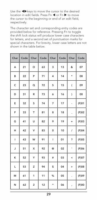
Use the keys to move the cursor to the desired location in edit fields. Press Fn or Fn to move the cursor to the beginning or end of an edit field, respectively.
The character set and corresponding entry codes are provided below for reference. Pressing Fn to toggle the shift lock status will produce lower case characters for letters, and a second set of punctuation marks for special characters. For brevity, lower case letters are not shown in the table below.
30
Creating Your First New Ojects-Object EditWhen you enter Program Menu, the scanner will provide the following Programming Menu options and is ready for you to enter the first Objects into the memory:
Global Settings
Edit System
Add System
Add Conv Freq
When an Object is displayed, press SEL or MENU to customize your Object and Set Scanlist.
Essential Conventional Channel parameters
By default, your new CONV object will be tagged “Channel”. If you'd like to change this, just scroll the screen down one click until the flashing cursor highlights the Tag: field, then press SEL to edit the tag. You can move the cursor around using the keys on the 4-way push button pad, use the (.) key to clear the old character, or press SKIP to erase the entire field. To enter text, use the or find the letter you want to enter on the front panel of the radio, press the numeric key beneath it, then press 1, 2, 3, or 4 depending on the position of the letter in the group for that number.
For example, to enter FIRE, press:
3 3 F
4 3 I
7 3 R
3 2 E
Press the SEL key to store the new tag information for your CONV object.
Now you are ready to store your first CONV object. There are other parameters that you can change, and we invite you to scroll through the CONV menu to see the other settings that are available.
When you're ready, scroll to save changes, press the SEL key to save your new conventional object. Once the object is saved, you can continue to enter other new objects, or press SEL to start scanning! The cursor to the beginning or end of an edit field, respectively.
31
Essential Trunking Talkgroup parameters
As a standalone object, a TRGP object is really no more complicated than a CONV object. The trunking system (TSYS) that the TGRP is a member of must be specified. Each talkgroup has a digital “address” on the trunking system, which is called the talkgroup ID, and this must be provided. We also recommend that you label your TGRP object by giving it a name in the TAG field. This will make it easier for you to find the TGRP object later, and identify it when the scanner stops to monitor activity.
Setting up and using a Trunking System (TSYS) object
We just mentioned that the TSYS is an essential parameter needed in order for a TGRP object to function properly and receive radio traffic. The TSYS object has its own set of essential parameters, and these parameters vary depending on the type of trunked radio system you plan to monitor. If you are a reasonably experienced user you probably already know what the essential parameters are for the system you wish to monitor. For example, each TSYS must correctly specify the type of system being monitored, the control channel or LCN frequencies used by the system, and so on. A detailed description of each type of system supported by this radio and the essential parameters required to make the different types of trunked radio systems work properly is provided in the help section of the EZ Scan software.
IMPORTANT: The first time you make a TGRP for a particular trunked radio system, you must also create a TSYS that contains the system parameters associated with that trunked radio system. Once you create a TSYS object for the trunked radio system, you can use the TSYS object over and over again without having to re-enter all of the system data.
32
Adding a New Trunk SystemFrom the Program Menu, Select Add System, Select System type.
< Motorola > < EDACS > < LTR > <P25> <DMR>
Press SEL will enter the -Add System- menu.
Scroll to Edit Sites, Press SEL to enter –Edit Sites- menu.
Scroll to 0001: New site, press SEL to enter -Edit Site- menu.
Edit Frequencies and Alpha Tag using text method described earlier.
Press SEL after making your edits, scroll to Save Changes, press SEL returns to –Edit Sites-.
From here you can select Add New, Delete Current, or Back to system. Selecting Back to system will take you to the –Add System- menu where you can Cancel Changes, Save Changes, Edit Sites, Add Talkgroup, and Alpha Tag.
When done, scroll to Save Changes, press SEL returns to the –Program Menu-. Press MENU returns you to the –Main Menu-.
Next you need to enter control channel frequencies for Motorola and P25 systems or all system frequencies for other system types. Select the 01: position and using the number keys, and enter the first frequency and press SEL. Continue entering frequencies until done. Press MENU and SEL to save.
If the system is narrow band FM, select NFM. Normally, no other input is needed. Scroll up proceed to Save Changes. Press Menu to return to the Add System menu.
33
Adding the First Talk Group to a New Trunk System Under Main Menu, Program Menu, Edit System:
Scroll the display if necessary to select the system where you will add the new talkgroup. Press Select.
Scroll the display by pressing the down arrow until you get to Add Talkgroup and press Select.
Your radio's display should appear as follows:
-Add TGRP-
Cancel Changes
Save Changes
TGID Wildcard
Radio ID
Alpha Tag
In the following step you will store a Wildcard talkgroup with the number 65535. If you would rather store a TGRP object for a specific talkgroup ID, just press the number keys to enter the talkgroup ID of the desired talkgroup, then press the SEL key to store the ID.
HINT: TGRP objects are also used to receive Private/Individual Calls on trunking systems that support these call types. Simply check the Radio ID check box. A Wildcard TGRP object with Radio ID box checked will monitor all Private/Individual Calls seen on the system, or you can specify a radio ID to watch for in the ID: field.
Scroll down to Save Changes and perform the save.
The Wildcard talkgroup allows you to hear everything on the system.
If you entered an actual talk group, be sure to name this TID by changing Wildcard to the talkgroup’s actual name. You'll want to scroll down two more clicks to the Tag: field and enter an easy to remember name for your talkgroup that corresponds with its purpose on the trunked radio system. For this example, lets assume that this is a police dispatch talkgroup, and we would like to use the name “POLICE DISPATCH” for the tag. Scroll to the Tag: field and press the SEL key. Using the text entry methods that you have previously employed for naming your CONV and TSYS objects, name your new talkgroup “POLICE DISPATCH”:
34
7 1 P
6 3 O
5 3 L
4 3 I
2 3 C
3 2 E
. <space>
3 1 D
4 3 I
7 4 S
7 1 P
2 1 A
8 1 T
2 3 C
4 2 H
Press SEL to store the name, then press SEL to store the TGRP as a new object. As with the other object types, there are many other parameters you can edit for the TGRP, but for now, that's all you have to do to start monitoring traffic on that TGRP! To add more TGRPs on the same system, follow the same steps above, this time specifying the TSYS that you just created. To create TGRPs on a different system, follow the steps above, specify a NEW system, and provide the correct parameters for that system, as shown above. With regard to trunked radio systems, it is important to note that a "system" cannot be scanned. If one wishes to monitor radio traffic on a trunked radio system, one must create a TGRP object. A TGRP object includes the parameters for a trunked radio system so that it will operate properly. Trunking system(TSYS) parameters are stored as a separate "configuration object", and can be used over and over again in other talkgroup objects on the same trunked radio system.
Also with regard to trunked radio systems, it is important to note that a talkgroup object may be configured in one of four different ways to monitor traffic on a trunked radio system. They are as follows:
• Wildcard Talkgroup: will monitor all talkgroup call radio traffic on the desired trunked radio system
• Talkgroup with TGID: will only monitor talkgroup call radio traffic on the specified TGID (enter the desired talkgroup in the ID: field of the TGRP object to scan a specified ID)
35
• Wildcard Private Call: will monitor all private call radio traffic on the desired trunked radio system (in the TGID field, and set the Type field to Private)
• Private Call with ID: will only monitor private call radio traffic on the specified TGID (enter the desired Radio ID in the TGID field, and set the Type field to Private)
NOTE: For now, just let your new objects go to the default Scan List. Later in this section we will show you how you can group your objects into Scan Lists.
Talkgroup Object (TGRP)Talkgroup Object (TGRP) A Trunking Talkgroup Object (TGRP) is a record that stores the parameters for a trunked talkgroup on a trunked radio system. When you create a TGRP object, you are creating an object that will allow you to scan and monitor a talkgroup on a particular trunked radio system.
Importing DMR systems using the EZ Scan PC Application Importing DMR systems using the EZ Scan PC Application is nearly identical to importing any other type of trunked radio system. The most significant difference between DMR systems verses other types of systems is that the scanner does not use the DMR control channel. Instead, your scanner will attempt to scan all sites and all frequencies for each site to determine if there is activity to be monitored.
When programming DMR systems, it is recommended that you select/import and/or only enable the sites that you believe will be in range of your location.
NOTE: The following steps assume you have “Set Location” to off in the EZ Scan PC Application General Settings tab and/or you have selected the “Preferred” type for importing systems.
1. Click on the Library Import tab.
2. In the Select State/Province list, click on your state.
3. In the data type box to the right, double-click on Counties/Cities.
4. In the Counties/Cities list on the left, click on your county.
5. In the Data Type box to the right, double-click on
Systems.
36
DMR systems are denoted in this list by the type Connect Plus, Capacity Plus, Linked Cap Plus, and Hytera XPT in the last column of the displayed list of systems.
1. Select the system you want to import by clicking on the selection box to the left of the system.
2. For systems that may have more than one transmitter site, click on the Sites button and select the sites you want to import.
3. Load only selected talkgroups on this system by pressing the Talkgroups button.
4. After your Site and Talkgroup selections have been made, press the Import Selected Channels button.
5. Select the scanlist you want to import this system into by clicking on the box in the SEL column.
a. NOTE: You have options that may be set by clicking on the Import Options button.
b. Add a “wildcard” to search for new talkgroups and another to monitor for direct, radio to radio “Private Calls”.
6. To perform the import, click the Import Channels button on the lower left side of the screen.
7. After the import, you’ll have the option to return and import more systems.
Searching for new/unknown talkgroups or Private Calls and to selectively enable sites for a given imported system
By default, you will hear only those talkgroups that have been identified by other users which have been submitted to Radio Reference for inclusion in the Radio Reference Database.
If you didn’t select the wildcard option(s) during import, you still have the option of enabling search for new talkgroups on the system you imported by adding a talkgroup “wildcard” object to your scanlist.
1. Click on the Trunked Radio Systems tab at the top of the EZ Scan PC Application.
2. Click on the Alpha Tag label field of the system you imported to select it. After selecting the system, the Trunked System Site Information panel will populate at the bottom of the screen.
3. If not already selected/displayed, click on the Site Details tab.
37
4. Determine which site(s) you want to monitor and lockout the other sites by clicking on the box in the column labeled L/O.
a. NOTE: The Multi-Site Settings options below the sites panel have no affect when monitoring DMR systems on your scanner.
5. Click on the Talkgroup Details tab of the Trunked System Site Information panel to see the talkgroups currently loaded into your configuration.
6. If a wildcard object does not already exist for this system, click the Add Wildcard button on the right side of the screen. When the scanlist pop-up panel appears, select the scanlist that you want to assign the wildcard object to.
7. To add a Radio ID wildcard object, click on the Radio ID Details tab and click on the Add Wildcard button to the right. When the scanlist pop-up panel appears, select the scanlist that you want to assign the wildcard object to.
Don’t forget to write your configuration to the SD card of your radio using the Scanner/SD Card menu option at the top of the EZ Scan PC Application.
Manually creating/adding DMR systems using the EZ Scan PC ApplicationIf you learn of a new DMR system that you want to configure for your scanner or if the DMR system listed on the Radio Reference Database has no talkgroups listed, you may need to manually create a new DMR system in the EZ Scan PC Application.
To manually create/add a new DMR system
1. Click on the Trunked Radio Systems tab at the top of the EZ Scan PC Application.
2. Click on the New button to on the right side of the Trunked Radio Systems screen. A new row will appear in the Trunked Radio Systems section.
3. Click on the Alpha Tag column field of the newly created system and enter the name of the system.
4. Click on the Type column of the new system row and select DMR.
5. Click on the Country column and set the country.
6. Click on the AGC column and set it to On.
38
7. With the new system row highlighted at the top of the display, you will see the Trunked System Site Information section on the bottom half of the screen.
8. If not already selected/displayed, click on the Site Details tab.
9. Click on the “Site 001” label in the Alpha Tag column to select and enable editing of the site frequencies.
10. Enter the site frequencies in the Frequency column of the Site Frequencies tab.
a. NOTE: For best performance enter all of the frequencies for the site (control, alternate, or otherwise). Do not enter duplicate frequencies.
11. Click on the Talkgroup Details tab of the Trunked System Site Information panel to see talkgroups currently loaded into your configuration.
12. If a wildcard object does not already exist for this system, click the Add Wildcard button on the right side of the screen. When the scanlist pop-up panel appears, select the scanlist that you want to assign the wildcard object to.
13. To add a Radio ID wildcard object, click on the Radio ID Details tab and click on the Add Wildcard button to the right. When the scanlist pop-up panel appears, select the scanlist that you want to assign the wildcard object to.
Don’t forget to write your configuration to the SD card of your radio using the Scanner/SD Card menu option at the top of the EZ Scan PC Application.
39
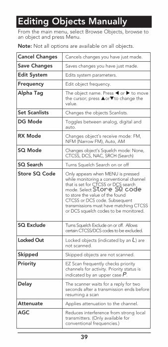
Editing Objects ManuallyFrom the main menu, select Browse Objects, browse to an object and press Menu.
Note: Not all options are available on all objects.
Cancel Changes Cancels changes you have just made.
Save Changes Saves changes you have just made.
Edit System Edits system parameters.
Frequency Edit object frequency.
Alpha Tag The object name. Press or to move the cursor; press orto change the value.
Set Scanlists Changes the objects Scanlists.
DG Mode Toggles between analog, digital and auto.
RX Mode Changes object’s receive mode: FM, NFM (Narrow FM), Auto, AM
SQ Mode Changes object’s Squelch mode: None, CTCSS, DCS, NAC, SRCH (Search)
SQ Search Turns Squelch Search on or off
Store SQ Code Only appears when MENU is pressed while monitoring a conventional channel that is set for CTCSS or DCS search mode. Select Store SQ code to store the value of the found CTCSS or DCS code. Subsequent transmissions must have matching CTCSS or DCS squelch codes to be monitored.
SQ Exclude Turns Squelch Exclude on or off. Allows certain CTCSS/DCS codes to be excluded.
Locked Out Locked objects (indicated by an L) are not scanned.
Skipped Skipped objects are not scanned.
Priority EZ Scan frequently checks priority channels for activity. Priority status is indicated by an upper case P.
Delay The scanner waits for a reply for two seconds after a transmission ends before resuming a scan
Attenuate Applies attenuation to the channel.
AGC Reduces interference from strong local transmitters. (Only available for conventional frequencies.)
40
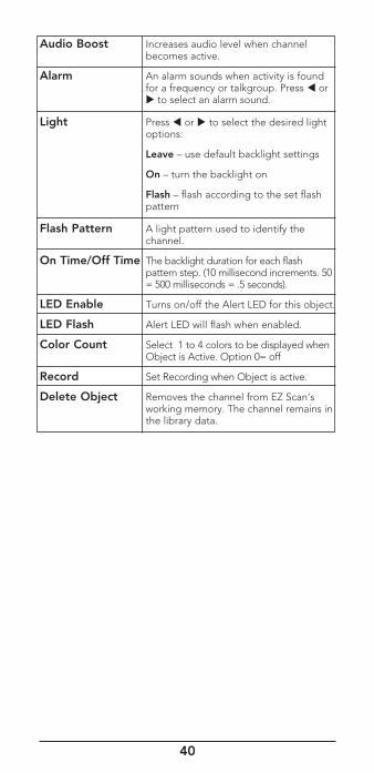
Audio Boost Increases audio level when channel becomes active.
Alarm An alarm sounds when activity is found for a frequency or talkgroup. Press or to select an alarm sound.
Light Press or to select the desired light options:
Leave – use default backlight settings
On – turn the backlight on
Flash – flash according to the set flash pattern
Flash Pattern A light pattern used to identify the channel.
On Time/Off Time The backlight duration for each flash pattern step. (10 millisecond increments. 50 = 500 milliseconds = .5 seconds).
LED Enable Turns on/off the Alert LED for this object.
LED Flash Alert LED will flash when enabled.
Color Count Select 1 to 4 colors to be displayed when Object is Active. Option 0= off
Record Set Recording when Object is active.
Delete Object Removes the channel from EZ Scan’s working memory. The channel remains in the library data.
41
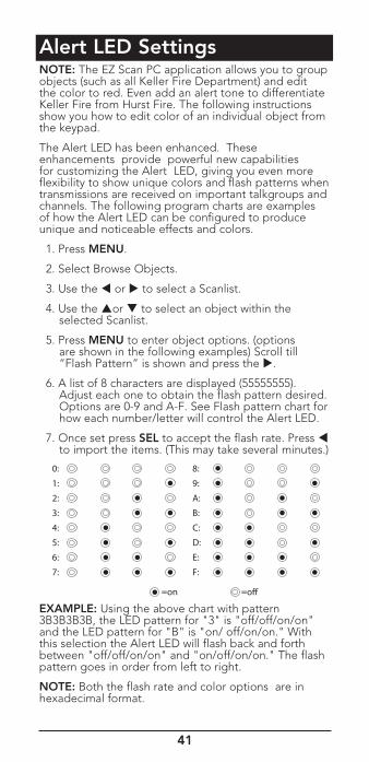
Alert LED SettingsNOTE: The EZ Scan PC application allows you to group objects (such as all Keller Fire Department) and edit the color to red. Even add an alert tone to differentiate Keller Fire from Hurst Fire. The following instructions show you how to edit color of an individual object from the keypad.
The Alert LED has been enhanced. These enhancements provide powerful new capabilities for customizing the Alert LED, giving you even more flexibility to show unique colors and flash patterns when transmissions are received on important talkgroups and channels. The following program charts are examples of how the Alert LED can be configured to produce unique and noticeable effects and colors.
1. Press MENU.
2. Select Browse Objects.
3. Use the or to select a Scanlist.
4. Use the or to select an object within the selected Scanlist.
5. Press MENU to enter object options. (options are shown in the following examples) Scroll till “Flash Pattern” is shown and press the .
6. A list of 8 characters are displayed (55555555). Adjust each one to obtain the flash pattern desired. Options are 0-9 and A-F. See Flash pattern chart for how each number/letter will control the Alert LED.
7. Once set press SEL to accept the flash rate. Press to import the items. (This may take several minutes.)
EXAMPLE: Using the above chart with pattern 3B3B3B3B, the LED pattern for "3" is "off/off/on/on" and the LED pattern for "B" is "on/ off/on/on." With this selection the Alert LED will flash back and forth between "off/off/on/on" and "on/off/on/on." The flash pattern goes in order from left to right.
NOTE: Both the flash rate and color options are in hexadecimal format.
42
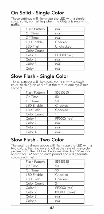
On Solid - Single ColorThese settings will illuminate the LED with a single color, solid, no flashing when the Object is receiving traffic. Flash Pattern n/a On Time n/a Off Time n/a LED Enable Checked LED Flash Unchecked Color Count 1 Color 1 FF0000 (red) Color 2 n/a Color 3 n/a Color 4 n/a
Slow Flash - Single ColorThese settings will illuminate the LED with a single color, flashing on and off at the rate of one cycle per second. Flash Pattern 55555555 On Time 50 Off Time 50 LED Enable Checked LED Flash Checked Color Count 1 Color 1 FF0000 (red) Color 2 n/a Color 3 n/a Color 4 n/a
Slow Flash - Two ColorThe settings shown above will illuminate the LED with a two colors, flashing on and off at the rate of one cycle per second. The LED will be illuminated for 1/2 second and off for 1/2 second each period and will alternate colors each flash. Flash Pattern 55555555 On Time 50 Off Time 50 LED Enable Checked LED Flash Checked Color Count 2 Color 1 FF0000 (red) Color 2 0000FF (blue) Color 3 n/a Color 4 n/a
43
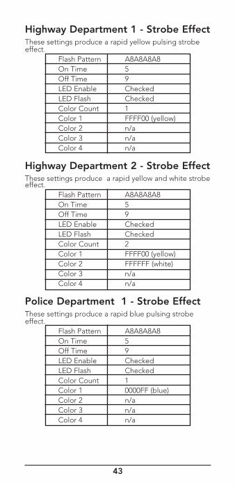
Highway Department 1 - Strobe EffectThese settings produce a rapid yellow pulsing strobe effect. Flash Pattern A8A8A8A8 On Time 5 Off Time 9 LED Enable Checked LED Flash Checked Color Count 1 Color 1 FFFF00 (yellow) Color 2 n/a Color 3 n/a Color 4 n/a
Highway Department 2 - Strobe EffectThese settings produce a rapid yellow and white strobe effect. Flash Pattern A8A8A8A8 On Time 5 Off Time 9 LED Enable Checked LED Flash Checked Color Count 2 Color 1 FFFF00 (yellow) Color 2 FFFFFF (white) Color 3 n/a Color 4 n/a
Police Department 1 - Strobe EffectThese settings produce a rapid blue pulsing strobe effect. Flash Pattern A8A8A8A8 On Time 5 Off Time 9 LED Enable Checked LED Flash Checked Color Count 1 Color 1 0000FF (blue) Color 2 n/a Color 3 n/a Color 4 n/a
44
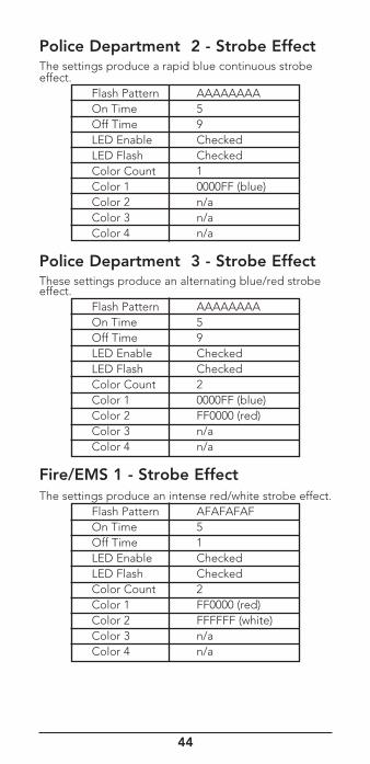
Police Department 2 - Strobe EffectThe settings produce a rapid blue continuous strobe effect. Flash Pattern AAAAAAAA On Time 5 Off Time 9 LED Enable Checked LED Flash Checked Color Count 1 Color 1 0000FF (blue) Color 2 n/a Color 3 n/a Color 4 n/a
Police Department 3 - Strobe EffectThese settings produce an alternating blue/red strobe effect. Flash Pattern AAAAAAAA On Time 5 Off Time 9 LED Enable Checked LED Flash Checked Color Count 2 Color 1 0000FF (blue) Color 2 FF0000 (red) Color 3 n/a Color 4 n/a
Fire/EMS 1 - Strobe EffectThe settings produce an intense red/white strobe effect. Flash Pattern AFAFAFAF On Time 5 Off Time 1 LED Enable Checked LED Flash Checked Color Count 2 Color 1 FF0000 (red) Color 2 FFFFFF (white) Color 3 n/a Color 4 n/a
45
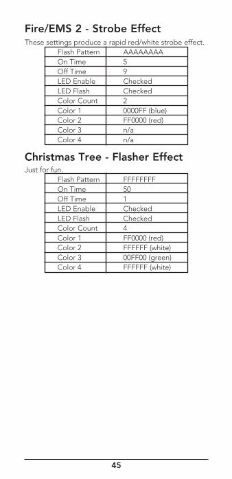
Fire/EMS 2 - Strobe EffectThese settings produce a rapid red/white strobe effect. Flash Pattern AAAAAAAA On Time 5 Off Time 9 LED Enable Checked LED Flash Checked Color Count 2 Color 1 0000FF (blue) Color 2 FF0000 (red) Color 3 n/a Color 4 n/a
Christmas Tree - Flasher EffectJust for fun. Flash Pattern FFFFFFFF On Time 50 Off Time 1 LED Enable Checked LED Flash Checked Color Count 4 Color 1 FF0000 (red) Color 2 FFFFFF (white) Color 3 00FF00 (green) Color 4 FFFFFF (white)
46
Recording and PlaybackYour scanner features a powerful audio recording system that captures transmissions that occur on selected Objects to the Micro SD card using the high quality, industry standard .AU audio file format.
For example, a 2GB Micro SD card with a very large scanning configuration (e.g., 500 MB) still leaves room for over 50 hours of recording time and thousands of recorded transmissions! Here are just a few of the things you can do with the audio recording system:
• Record all transmissions that occur on talkgroups or channels that are of interest to you for later review.
• Perform attended or unattended searches for new frequencies, automatically storing audio with frequency information for all transmissions found while searching.
• Record all transmissions that occur on ALL talkgroups or channels, providing an instant recall function to replay a prior transmission that was missed or unintelligible.
Audio recording is not enabled by default. To enable audio recording, make sure that the Enable Record option in the Global Settings menu is checked, and set the Record flag in any Objects that you wish to record. You may wish to record audio for all of your programmed Objects, which provides the ability to instantly replay any transmission that the radio receives in cases where the traffic may be difficult to copy.
When recording is enabled radio wide and for selected Objects, you will see the icon flash in the display when the audio recorder is actively recording audio information.
When the Micro SD card is almost full, the F icon will appear in the display to indicate that recording is suspended. Delete or archive old audio files to make room for new recordings. To playback recorded audio files:
1. From the Main Menu, select Playback to enter the Playback System.
2. The Playback System will place you at the last audio file that was recorded by the radio. Press the /II/SEL key to play the file, or use the and keys to scroll to another file for playback.
47
3. While playing a file, the and keys set the playback volume, and the or keys move backward and forward in the file being played in five second increments. The SKIP key ends playback of the current file.
4. After scrolling to a file, you can press the MENU key for a list of playback options.
Main Menu jumps to the Main Menu.
• Back jumps back to the list of recorded files.
• Play From Here plays the current recording and all recordings afterwards.
• Delete All deletes all recorded audio files.
• Delete Earlier deletes recorded audio files prior to the selected audio file.
• Delete Later deletes the selected audio file and all recorded audio files after the selected file.
The EZ Scan Software includes advanced audio file playback and management features in addition to the audio playback and management features in the radio.
Using IF OutputYour scanner can provide its IF/discriminator output signal to the headphone jack. The IF/discriminator output is unsquelched and unfiltered, making it ideal for third party signal analysis and decoding software and hardware.
To activate IF Output mode:
1. Press MENU.
2. Scroll to the Program Menu, Press SEL, Global Settings, Press SEL to continue.
3. Scroll past the Expert section to the IF Out setting.
4. Press the to scroll through the available options:
Off = disables the IF output function.
HP = routes the IF/discriminator to the headphone jack.
HP/SP = routes the IF/discriminator signal to the headphone jack and the speaker.
48
Internal Clock/CalendarYour scanner includes a real time clock/calendar that is used to correctly date and time stamp recorded audio files. The first time you power on your scanner, you will be prompted to set the time and date.
If batteries are allowed to fully discharge, or if they are removed from the scanner for more than a few minutes, the date and time will need to be set again. You can also set the date and time over the USB connection using the EZ Scan Software, or directly on the radio using the Set Clock function in the Main Menu.
Monitoring and ScanningWhen programmed, your scanner provides two basic functions for scanning radio transmissions:
• Monitoring – Listening to a single object.
• Scanning – Checking multiple saved objects, stopping when a transmission is detected.
To scan more quickly, you can skip or lock out frequencies that you do not wish to scan. A skipped frequency is ignored during the current scan; a locked out frequency is ignored for all scans unless it is unlocked.
To monitor a frequency or talkgroup:
1. From the main menu, select Browse Objects, then press .
2. Use the direction keys to browse Scanlists and objects.
3. Press /II/SEL to monitor the displayed frequency.
4. Press or to select another object or press /II/SEL to begin scanning.
To scan your active Scanlists:
1. Press MENU.
2. Select Scan from the main menu and press or /II/SEL.
3. To pause the scan, press /II/SEL when scanner stops on a transmission. To resume scanning, press /II/SEL again.
49
To enable or disable Scanlists:
While scanning, pressing 1 thru 200 will toggle the selected scanlist on or off. Each button must be pressed within 2 second of the last. If more than 1 scanlist will be toggled on or off, press the decimal once as a separator. Pressing the decimal twice will end the sequence.
Example: If you wish to toggle scanlist 9 you press 9 If you wish to toggle scanlist 9, 11, and 22 simply press the following 9 . 11 . 22 or 9 . 11 . 22 . or 9 . 11 . 22..
To lock out objects:
1. From main menu, select Browse Objects, then press .
2. Use the keys to browse objects then press MENU.
3. Select Locked Out and press . A checkmark ( ) indicates Lockout is selected. A square () indicates Lockout is disabled. An uppercase L in the display indicates a locked out frequency.
NOTE: The SKIP button can be programmed in the Global Settings Menu (first option under the Expert section) to perform the Lockout function.
To skip transmissions while scanning:
1. Wait for scanner to stop on the transmission and press SKIP. An uppercase S in the display indicates a skipped object.
2. To skip a specific object, you can browse to the object and press SKIP.
3. To restore a skipped object, browse to it and press SKIP.
4. To restore all skipped objects, in the main menu, select Restore Skipped and press .
NOTE: If the specific object is locked out vs. skipped the SKIP button may have been programmed as Lockout function.
50
TIP: Consider how you plan to organize your objects for scanning. You can organize your scan lists geographically, assigning objects for your location in one list and objects for other locations in different lists. You can organize your scan lists by trunking system, assigning TGRP objects associated with specific trunked radio systems to separate lists.
To rename a Scanlist:
1. Select Scanlist from the main menu, and then press .
2. Select a Scanlist and press . The Scanlist name appears.
3. Press or to move the cursor; press or to change the character. Press SKIP to delete a character.
To set priority objects. Priority is used only when you want regular scanner operation interrupted to hear something on your priority object(s):
1. Browse to the object and press Menu.
2. Select Priority and press . A checkmark ( ) indicates an Priority is selected. A square () indicates Priority is disabled.
NOTE: To set priority, Priority Mode must be enabled in the Configuration menu. Setting any object as a priority can cause normal scanner interruption.
Scanlist and Scan SetsThere are 20 Scan Sets that work in conjunction with Scanlists to provide additional scan object selection capability and flexibility. Each Scan Set contains a list of all 200 normal Scanlists plus the special Skywarn® Scanlist.
With Scan Sets you can quickly select large groups of Scanlists to enable or disable, just by enabling or disabling the Scan Sets that contain the desired groups of Scanlists, instead of individually editing the list of enabled Scanlists every time you want to change the group of Scanlists you wish to monitor.
For example:
On Scanlists 01 through 30 you decide to put all of City1. On Scanlists 31 through 50 you decided to put all of City 2, on Scanlists 51 through 62 you decided to put all of City 3. When you move from city to city, it would take some time to individually toggle off the unwanted scanlists and toggle on the new ones. This is where Scan sets come in.
51
NOTE: When you start a scan, the first thing the scanner does is check to see what Scan set(s) is (are) enabled. It finds Scan set 01 on by default. Next it checks to see what Scanlists are permitted in Scan set 01 and it finds that every scanlist is checked (all are allowed). This means the scanner will use the checked Scanlist boxes to control what Scanlists are scanned. If you have objects stored and the scanner reports, “Nothing to Scan!” Check to see if you accidentally unchecked the box for Scan set 01.
Rename Scan set 01 to City 1 name and uncheck all boxes 31 and up. Leave Skywarn® checked so you can enable Skywarn if you are in City 1. Rename Scan set 02 to City 2 name and check scanlist boxes 31 through 50 and Skywarn, all others should be off. And finally, rename Scan set 03 to City 3 name and check boxes for Scanlists 51 through 62 and Skywarn.
Now when changing from city to city, simply uncheck the Scanset box for the city you are leaving and check the box for the one you are entering.
SearchingYou can locate active frequencies quickly and easily using one of the Scanner’s three convenient frequency search modes:
• Spectrum Sweeper – sweeps rapidly through frequency ranges in 1MHz blocks. Unlike the frequency counter method used in other scanners, Spectrum Sweeper is far more sensitive, arguably just as fast and the only technology that lets you lock out and keep searching in the same band.
• Service Search – searches through frequencies used by the following radio services: Public Safety, Aircraft, Railroad, Amateur, CB,Marine, and FRS/ GMRS/MURS. This is a good way to find activity on local frequencies.
• Limit Search – searches within a range of frequencies that you define.
To use Spectrum Sweeper:
1. In the main menu, select Search, and press to enter the search menu.
2. Select Spectrum Sweeper and press .
3. Select All Bands or Public Safety and press right () to start the search. Spectrum Sweeper sweeps through frequency ranges in 1 MHz blocks.
4. Press MENU to stop search which enters Sweeper menu where you can select fewer bands to search.
52
To perform a Service Search:
1. In the main menu, select Search, and press to enter to the search menu.
2. Select Service Search and press .
3. Scroll through the available services, select a service, and press to start the search.
4. Press MENU to stop search which enters service menu.
To perform a Limit Search:
1. In the main menu, select Search, and press to enter to the search menu
2. Select Limit Search, and press . The search begins immediately.
3. To change the search range, press MENU.
4. Scroll to Lo and press .
5. Press or to move the cursor; press or to change the value.
6. Press SEL to save the new value and return to the search menu.
7. Scroll to Hi and press .
8. Press or to move the cursor; press or to change the value.
9. Press SEL to save the new value and return to the search menu.
10. Press to continue the search.
11. Press MENU to stop search when enters Limit Menu.
To save found frequencies:
1. Press MENU.
2. Then select Store Channel and press SEL. EZ Scan adds the frequency to the default Scanlist and names it based on the search type.
53
Search SettingsTo change search settings, press MENU while the search is active.
Spectrum Sweeper Settings
• Atten – Attenuation. On or Off.
• Zeromatic – On or off.
• Delay –How long scanner waits after a transmission before resuming.
• Special Mode – Skips 1MHz block where you have skipped five or more frequencies. Special Mode is useful when you are close to many high-power transmitters that are close together in frequency.
• Frequency Ranges – Defines a frequency range to focus a search.
Service Search Settings
• Atten – Attenuation. On or Off.
• Zeromatic – On or off.
• Delay –How long scanner waits after a transmission before resuming.
• Frequency Ranges – Defines a frequency range to focus a search.
• Rx Mode – Set the RX modulation mode to automatic, or forces AM mode or FM mode. RX Mode functions in Aircraft and Amateur bands, Press or to change.
Limit Search Settings
• Atten – Attenuation. On or Off.
• Zeromatic – On or off.
• Delay –How long scanner waits after a transmission before resuming.
• Lo – Lowest frequency in the search range.
• Hi – Highest frequency in the search range.

54
Saving Found CTCSS, DCS or NAC CODESWhen importing objects from the Library, squelch codes are automatically imported. If this information is missing, your scanner can quickly identify these codes during a search, if present. When a channel includes a CTCSS, DCS or NAC code, the code appears on the bottom line of the display, followed by an“ ”, which indicates a valid CTCSS, DCS or NAC code:
CTCSS 127.3
To save the found code with the channel:
1. When a CTCSS or DCS code is found by the search feature, press MENU. Store SQ code appears.
2. Press SEL.
After the code is saved, the scanner will only stop on transmissions that have a matching CTCSS, DCS or NAC squelch code present.
NOTE: In the Global Settings Menu, Simple Display must be unchecked to display and save found CTCSS, DCS or NAC codes.
55
Weather MonitoringA weather alert tone includes a digitally-encoded SAME (Specific Area Message Encoding) signal, FIPS (Federal Information Processing Standard) code, and an event code.
Before you can use SAME Stand by Mode, you must program at least one FIPS code. Unless you are near a county boarder, enter only the FIPS code for your county. This prevents alerting when events happen in nearby counties.
To receive severe weather broadcasts while scanning other channels, set your local NOAA channel as the Weather Priority channel, but be aware that normal scanner audio will be regularly interrupted when the scanner jumps away to check for a weather alert.
To program FIPS Codes:
1. Look up your local FIPS code(s) (located at:
www.NWS.NOAA.gov/NWR/indexnw.htm).
2. Press to activate Weather Mode, then press MENU.
3. Scroll to SAME1 Tag and press to name the channel. Press or to move the cursor; press or to change the character.
4. Scroll down to SAME 1 FIPS and press to enter a FIPS code. Press or to move the cursor; press or to change the character.
5. Scroll down to SAME1 Enable and press SEL or .
6. To program more FIPS codes (up to 10), repeat steps 3-5.
7. When finished, select Save Changes and press
SEL or .
NOTE: Programming only one FIPS code will result in alerts intended only for your county. For fringe areas, it may be beneficial to program a second FIPS code for nearby counties.
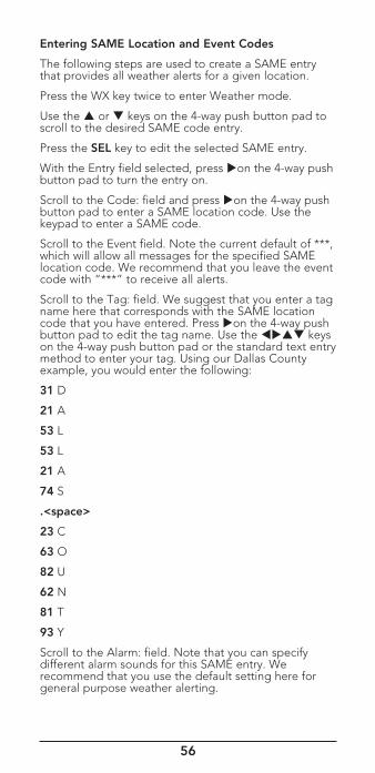
56
Entering SAME Location and Event Codes
The following steps are used to create a SAME entry that provides all weather alerts for a given location.
Press the WX key twice to enter Weather mode.
Use the or keys on the 4-way push button pad to scroll to the desired SAME code entry.
Press the SEL key to edit the selected SAME entry.
With the Entry field selected, press on the 4-way push button pad to turn the entry on.
Scroll to the Code: field and press on the 4-way push button pad to enter a SAME location code. Use the keypad to enter a SAME code.
Scroll to the Event field. Note the current default of ***, which will allow all messages for the specified SAME location code. We recommend that you leave the event code with “***” to receive all alerts.
Scroll to the Tag: field. We suggest that you enter a tag name here that corresponds with the SAME location code that you have entered. Press on the 4-way push button pad to edit the tag name. Use the keys on the 4-way push button pad or the standard text entry method to enter your tag. Using our Dallas County example, you would enter the following:
31 D
21 A
53 L
53 L
21 A
74 S
.<space>
23 C
63 O
82 U
62 N
81 T
93 Y
Scroll to the Alarm: field. Note that you can specify different alarm sounds for this SAME entry. We recommend that you use the default setting here for general purpose weather alerting.
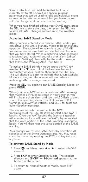
57
Scroll to the Lockout: field. Note that Lockout is currently set to off. Lockout is a special purpose parameter that can be used to lock out individual event or area codes. We recommend that you leave Lockout set to off for general purpose weather alerting.
When you have finished editing your SAME entry, press the SEL key to store the data, then press the SEL key to save all SAME changes and return to the Weather mode.
Activating SAME Stand by Mode
After you have entered your desired SAME codes, you can activate the SAME Standby Mode to begin standby operation. The radio will remain silent until a SAME transmission is received with a code that matches one that you have stored. When a matching SAME message is received, your radio will sound a siren alarm (adjust volume in Settings), then will play the audio message that follows the Warning Alert Tone (WAT).
To activate SAME standby mode, press the WX key, use the or keys to find the best weather radio transmitter for your location, then press the SKIP key. This will change to STBY to indicate that SAME Standby Mode is active, and the scanner will alert when a matching SAME message is received.
Press the SEL key again to exit SAME Standby Mode, or press MENU.
When your local NWS office activates a SAME warning that matches a FIPS code stored in your scanner, you will first hear a siren alarm and see the LED flash to alert you to the incoming alarm. The LED flashes RED for warnings, YELLOW for watches, and BLUE for tests and administrative messages.
The scanner sounds the siren until the NWS transmission of the 1050 Hz Warning Alert Tone (WAT) begins. Once the WAT begins, the scanner’s speaker will unmute, and you will hear the WAT play as an alert that the voice portion of the SAME warning is about to begin. You will then hear the voice portion of the SAME warning.
Your scanner will resume SAME Standby operation 90 seconds after the SAME warning starts. You may reset stand by mode by pressing the STBY soft key twice at any time.
To activate SAME Stand by Mode:
1. Press and then press or to select a NOAA channel.
2. Press SKIP to enter Stand by Mode. The speaker silences and SKIP = Normal appears at the bottom of the screen.
3. To return to Normal Weather Mode, press SKIP again.
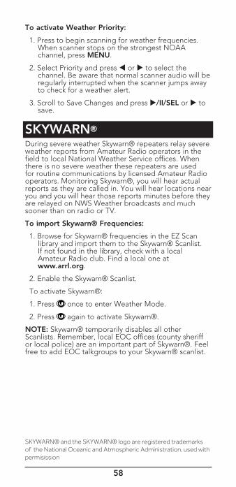
58
To activate Weather Priority:
1. Press to begin scanning for weather frequencies. When scanner stops on the strongest NOAA channel, press MENU.
2. Select Priority and press or to select the channel. Be aware that normal scanner audio will be regularly interrupted when the scanner jumps away to check for a weather alert.
3. Scroll to Save Changes and press /II/SEL or to save.
SKYWARN®
During severe weather Skywarn® repeaters relay severe weather reports from Amateur Radio operators in the field to local National Weather Service offices. When there is no severe weather these repeaters are used for routine communications by licensed Amateur Radio operators. Monitoring Skywarn®, you will hear actual reports as they are called in. You will hear locations near you and you will hear those reports minutes before they are relayed on NWS Weather broadcasts and much sooner than on radio or TV.
To import Skywarn® Frequencies:
1. Browse for Skywarn® frequencies in the EZ Scan library and import them to the Skywarn® Scanlist. If not found in the library, check with a local Amateur Radio club. Find a local one at www.arrl.org.
2. Enable the Skywarn® Scanlist.
To activate Skywarn®:
1. Press once to enter Weather Mode.
2. Press again to activate Skywarn®.
NOTE: Skywarn® temporarily disables all other Scanlists. Remember, local EOC offices (county sheriff or local police) are an important part of Skywarn®. Feel free to add EOC talkgroups to your Skywarn® scanlist.
SKYWARN® and the SKYWARN® logo are registered trademarks of the National Oceanic and Atmospheric Administration, used with permisission
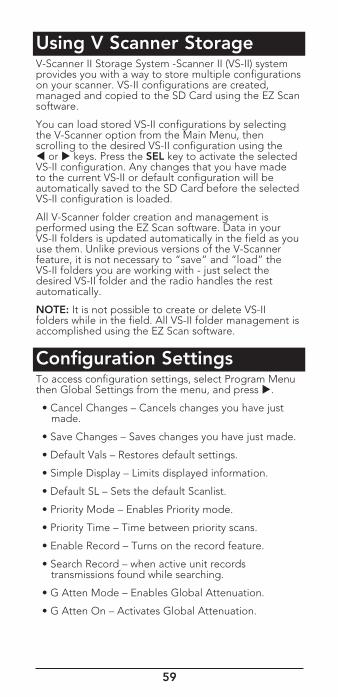
59
Using V Scanner StorageV-Scanner II Storage System -Scanner II (VS-II) system provides you with a way to store multiple configurations on your scanner. VS-II configurations are created, managed and copied to the SD Card using the EZ Scan software.
You can load stored VS-II configurations by selecting the V-Scanner option from the Main Menu, then scrolling to the desired VS-II configuration using the or keys. Press the SEL key to activate the selected VS-II configuration. Any changes that you have made to the current VS-II or default configuration will be automatically saved to the SD Card before the selected VS-II configuration is loaded.
All V-Scanner folder creation and management is performed using the EZ Scan software. Data in your VS-II folders is updated automatically in the field as you use them. Unlike previous versions of the V-Scanner feature, it is not necessary to “save” and “load” the VS-II folders you are working with - just select the desired VS-II folder and the radio handles the rest automatically.
NOTE: It is not possible to create or delete VS-II folders while in the field. All VS-II folder management is accomplished using the EZ Scan software.
Configuration SettingsTo access configuration settings, select Program Menu then Global Settings from the menu, and press .
• Cancel Changes – Cancels changes you have just made.
• Save Changes – Saves changes you have just made.
• Default Vals – Restores default settings.
• Simple Display – Limits displayed information.
• Default SL – Sets the default Scanlist.
• Priority Mode – Enables Priority mode.
• Priority Time – Time between priority scans.
• Enable Record – Turns on the record feature.
• Search Record – when active unit records transmissions found while searching.
• G Atten Mode – Enables Global Attenuation.
• G Atten On – Activates Global Attenuation.
60
• Search Dg AGC – Applies Digital AGC to found digital transmissions.
• G AGC Mode – Enables Global AGC.
• G AGC On – Activates Global AGC.
• Scan Sets Opt - Turns on Scan Set Feature.
• Sounds – Sets EZ Scan beeps and alert sounds.
• Alerts –Controls audio alerts.
• Key Beeps – Enables or disables key tones.
• Beep Volume – Sets key tone volume.
• Alert Volume –Object volume.
• Contrast – Sets the LCD contrast.
• LModeBAT – Backlight mode during battery operation.
• LModeEXT – Backlight mode (external power).
• Lite Area – Sets LCD and keypad lighting.
• Lite Time – Backlight duration.
• Lite Level –Controls backlight brightness.
• Welcome Text 1-5 – Sets the text displayed on five lines of the display when the scanner is first turned on.
Expert
• Skip - Programmed to “lockout” will permanently locks out an object when the SKIP button is pressed.
• Blink Time 1-2 – Controls the amount of time each item is displayed.
• Show Radio ID – Displays the Radio ID for trunked systems, if available. Tag Only.
• Use RID Alert –Controls alert for Radio ID transmissions.
• Show VC/CC – Displays voice and control channel. Simple Display must be unchecked. Show Radio ID will override if available.
• Show TGID – Displays talkgroup ID. Simple Display must be unchecked.
• Show Site Name – Displays trunking site name, only if two or more trunking system sites are programmed. Simple Display must be unchecked.
• CONV TGID – Displays the talkgroup ID for P25/ DMR conventional talkgroup calls. Simple Display must be unchecked.
61
• CONV Radio ID – Displays the Radio ID for P25 conventional calls. Simple Display must be unchecked.
• PC/IF CCDump – Streams ASCII Control Channel Dump data over the USB interface for trunking control channels.
To file – Stores ASCII Control Channel Dump data to the SD card.
Limit 100
Trim Logs
• Low Batt Time – Interval (seconds) between low battery alert sounds.
• Charge Time – Sets the radio charge time.
• TG Disp – Display format for talkgroup IDs.
• M36 Stat Bits – Uses status bits to track Motorola 3600 baud trunking talkgroup calls.
• M36 ENC
• EDACS Dig
• BandPlan – Selects USA or Canada.
• FlexStep - Permits using Split channel frequency.
• EncMode – For encrypted voice calls: Noise, Silent, or Tone.
• EncLevel – Sets the encrypted call tone level.
• IF Out –Routes the IF Discriminator signal to the headphone jack.
• DSP Level Adapt –Controls how fast the DSP adjusts to varying P25 levels (default: 64). Higher values = faster rates.
• ADC Gain – Controls input signal to CODEC (default: +0dB).
• DAC Gain – Sets output signal from CODEC, varying the audio level of decoded digital signals (default: +0dB).
• Auto Power On
At 00:00
Mode:
• Location Select
62
Using EZ Scan Software to Update the Scanner 1. Turn off the Scanner.
2. Connect the scanner to your computer using the USB cable supplied. The computer should recognize the scanner’s Micro SD card as a new drive. If an auto run screen appears, close it.
3. Select Check for CPU Firmware Update in the update menu.
4. Click Check for Updates on the update screen.
5. If there are available updates, click Update My Scanner.
6. Please be patient, this can take several minutes. When complete, click Done.
DSP Firmware Updates 1. Turn off the Scanner.
2. Connect the scanner to your computer using the USB cable supplied. The computer should recognize the scanner’s Micro SD card as a new drive. If an auto run screen appears, close it.
3. Select Check for DSP Firmware Update in the update menu.
4. Click Check for Updates.
5. If there are available updates, click Update My Scanner.
6. Please be patient, this can take several minutes. When complete, click Done.
Updating the Library (PC)To update the PC library:
1. Onthe Library Import Tab, click the Update Channels button. A second Import screen appears.
2. Click the Update Channels button. The library will be updated to the latest version.
NOTE: The procedure to update the RadioReference library requires an internet connection.
63
MaintenanceKeep the scanner dry; if it gets wet, wipe it dry immediately. Use and store the scanner only in normal temperature environments. Handle the scanner carefully; do not drop it. Keep the scanner away from dust and dirt, andwipe it witha damp cloth occasionally to keep it looking new.
Modifying or tampering with the scanner’s internal components can cause amalfunction andmight invalidate its warranty and void your FCC authorization to operate it.
Birdie FrequenciesBirdies are operating frequencies, which all scanners have, that are created inside the scanner’s receiver and can cause interference. If the interference is not severe, you adjusting the squelch might omit the birdie, but if you program one of these frequencies after a search, you will hear only noise on that frequency. If you suspect that a frequency you have programmed is being affected by a birdie, try removing the antenna.
Removing the antenna will help determine if the interfering signal is a birdie signal being generated inside of the scanner, or the result of an external interference source. If the noise on a frequency is not affected when the antenna is removed, it is almost certainly the result of a birdie. If the noise disappears when the antenna is removed, the noise is most likely coming from an external source. Moving the scanner may reduce or solve the issue.
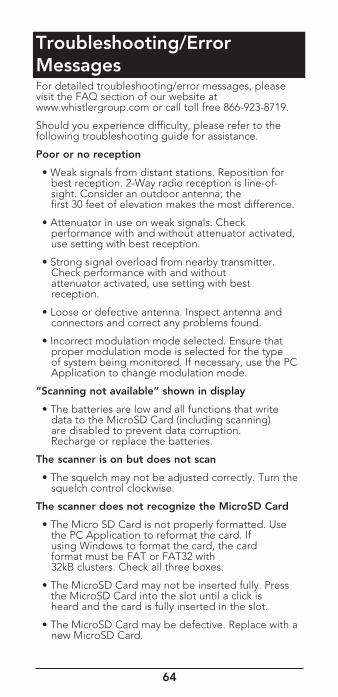
64
Troubleshooting/Error MessagesFor detailed troubleshooting/error messages, please visit the FAQ section of our website at www.whistlergroup.com or call toll free 866-923-8719.
Should you experience difficulty, please refer to the following troubleshooting guide for assistance.
Poor or no reception
• Weak signals from distant stations. Reposition for best reception. 2-Way radio reception is line-of- sight. Consider an outdoor antenna; the first 30 feet of elevation makes the most difference.
• Attenuator in use on weak signals. Check performance with and without attenuator activated, use setting with best reception.
• Strong signal overload from nearby transmitter. Check performance with and without attenuator activated, use setting with best reception.
• Loose or defective antenna. Inspect antenna and connectors and correct any problems found.
• Incorrect modulation mode selected. Ensure that proper modulation mode is selected for the type of system being monitored. If necessary, use the PC Application to change modulation mode.
“Scanning not available” shown in display
• The batteries are low and all functions that write data to the MicroSD Card (including scanning) are disabled to prevent data corruption. Recharge or replace the batteries.
The scanner is on but does not scan
• The squelch may not be adjusted correctly. Turn the squelch control clockwise.
The scanner does not recognize the MicroSD Card
• The Micro SD Card is not properly formatted. Use the PC Application to reformat the card. If using Windows to format the card, the card format must be FAT or FAT32 with 32kB clusters. Check all three boxes.
• The MicroSD Card may not be inserted fully. Press the MicroSD Card into the slot until a click is heard and the card is fully inserted in the slot.
• The MicroSD Card may be defective. Replace with a new MicroSD Card.
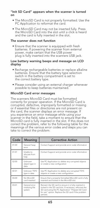
65
“Init SD Card” appears when the scanner is turned on
• The MicroSD Card is not properly formatted. Use the PC Application to reformat the card.
• The MicroSD Card may not be inserted fully. Press the MicroSD Card into the slot until a click is heard and the card is fully inserted in the slot.
The scanner does not function
• Ensure that the scanner is equipped with fresh batteries. If powering the scanner from external power, make certain that the USB power plug is fully inserted into the scanners USB jack.
Low battery warning beeps and message on LCD display
• Recharge rechargeable batteries or replace alkaline batteries. Ensure that the battery type selection switch in the battery compartment is set to the correct battery type.
• Please consider using an external charger whenever possible to keep batteries maintained.
MicroSD Card error messages
The scanners MicroSD Card must be formatted correctly for proper operation. If the MicroSD Card is corrupted, defective, improperly formatted or missing or if essential files or directories are not present on the card, the scanner displays an error message. If you experience an error message while using your scanner in the field, take a moment to ensure that the MicroSD card is fully inserted in the slot. If this does not correct the problem, refer to the following table for the meanings of the various error codes and steps you can take to correct the problem:
Code Meaning Corrective Action
01-00 General heap error
Contact Support and provide error code information
01-01 Unable to allocate from help
Contact Supprot and provide error code information
02-00 Unknown object type in data
Use PC Application to delete any corrupted objects or create a new configuration
02-01 Unknown TSYS type in data
Use PC Application to delete any corrupted TSYS objects or create a new configuration
03-00 No MicroSD card inserted
Ensure that a properly formatted MicroSD card is fully inserted and locked in the MicroSD slot.
03-01 General error initalizing file system
Reinsert the SD card to ensure it is fully inserted in locked in the SD card slot. If necessary, reformat the SD card using the PC Application "Prepare SD Card for use" option. Replace the SD card if the problem persists.
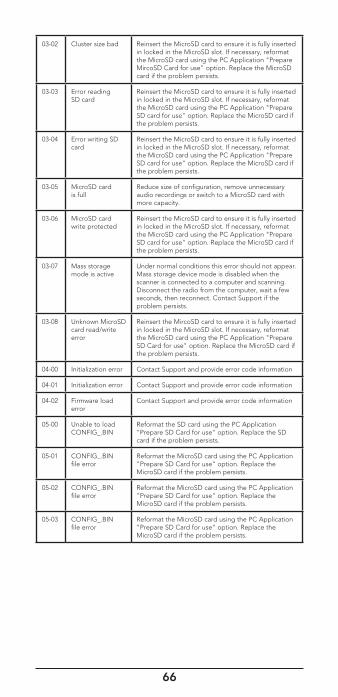
66
03-02 Cluster size bad Reinsert the MicroSD card to ensure it is fully inserted in locked in the MicroSD slot. If necessary, reformat the MicroSD card using the PC Application "Prepare MircoSD Card for use" option. Replace the MicroSD card if the problem persists.
03-03 Error reading SD card
Reinsert the MicroSD card to ensure it is fully inserted in locked in the MicroSD slot. If necessary, reformat the MicroSD card using the PC Application "Prepare SD card for use" option. Replace the MicroSD card if the problem persists.
03-04 Error writing SD card
Reinsert the MicroSD card to ensure it is fully inserted in locked in the MicroSD slot. If necessary, reformat the MicroSD card using the PC Application "Prepare SD card for use" option. Replace the MicroSD card if the problem persists.
03-05 MicroSD card is full
Reduce size of configuration, remove unnecessary audio recordings or switch to a MicroSD card with more capacity.
03-06 MicroSD card write protected
Reinsert the MicroSD card to ensure it is fully inserted in locked in the MicroSD slot. If necessary, reformat the MicroSD card using the PC Application "Prepare SD card for use" option. Replace the MicroSD card if the problem persists.
03-07 Mass storage mode is active
Under normal conditions this error should not appear. Mass storage device mode is disabled when the scanner is connected to a computer and scanning. Disconnect the radio from the computer, wait a few seconds, then reconnect. Contact Support if the problem persists.
03-08 Unknown MicroSD card read/write error
Reinsert the MircoSD card to ensure it is fully inserted in locked in the MicroSD slot. If necessary, reformat the MicroSD card using the PC Application "Prepare SD Card for use" option. Replace the MicroSD card if the problem persists.
04-00 Initialization error Contact Support and provide error code information
04-01 Initialization error Contact Support and provide error code information
04-02 Firmware load error
Contact Support and provide error code information
05-00 Unable to load CONFIG_.BIN
Reformat the SD card using the PC Application "Prepare SD Card for use" option. Replace the SD card if the problem persists.
05-01 CONFIG_.BIN file error
Reformat the MicroSD card using the PC Application "Prepare SD Card for use" option. Replace the MicroSD card if the problem persists.
05-02 CONFIG_.BIN file error
Reformat the MicroSD card using the PC Application "Prepare SD Card for use" option. Replace the MicroSD card if the problem persists.
05-03 CONFIG_.BIN file error
Reformat the MicroSD card using the PC Application "Prepare SD Card for use" option. Replace the MicroSD card if the problem persists.
67
Library Copyright NoticeThe data contained in EZ Scan’s library is provided by special arrangement with Radio Reference and is Copyright ©2016 RadioReference.com, LLC who retains sole ownership of the database. We ask that you respect this copyright by adhering to the following guidelines:
The library data is intended for your personal use only in conjunction with programming and using your EZ Scan. As such,RadioReference.com LLC grants the customer a non-exclusive single license to only be used with the EZ Scan radio and its associated PC software. The library shall not be copied or transferred to any third party in any electronic or physical form or posted on any website.
To decompile the Radio Reference database or convert it for use with another scanning receiver is expressly prohibited.
The Radio Reference database is developed and maintained by unpaid volunteers who are dedicated scanning hobbyists. The Library data is subject to errors in the user-submitted data reported to Radio Reference, and also to the system configuration changes that a radio system operator may make from time to time. Field-testing the library data for accuracy is not feasible.
For detailed radio system information worldwide, be sure to visit www.radioreference.com frequently. We encourage you to get involved with Radio Reference, and submit your own new or updated data to the database, which will result in future updated editions of the library.
Radio Reference is not responsible for errors, missions or outdated library data.
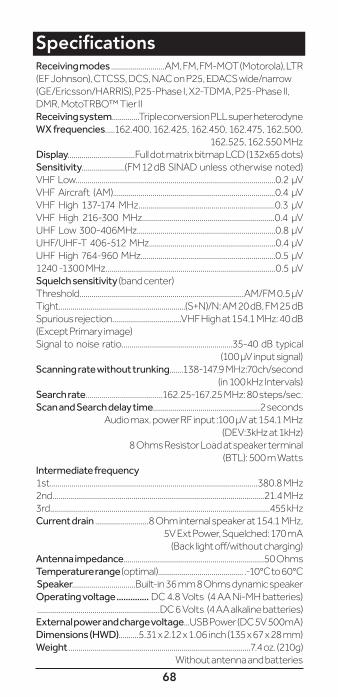
68
SpecificationsReceiving modes ...........................AM, FM, FM-MOT (Motorola), LTR (EF Johnson), CTCSS, DCS, NAC on P25, EDACS wide/narrow (GE/Ericsson/HARRIS), P25-Phase I, X2-TDMA, P25-Phase II, DMR, MotoTRBO™ Tier II Receiving system..............Triple conversion PLL super heterodyneWX frequencies.....162.400, 162.425, 162.450, 162.475, 162.500,
162.525, 162.550 MHzDisplay..................................Full dot matrix bitmap LCD (132x65 dots)Sensitivity......................(FM 12 dB SINAD unless otherwise noted)VHF Low.....................................................................................................0.2 μV VHF Aircraft (AM)..................................................................................0.4 μV VHF High 137-174 MHz.....................................................................0.3 μV VHF High 216-300 MHz...................................................................0.4 μV UHF Low 300-406MHz......................................................................0.8 μV UHF/UHF-T 406-512 MHz................................................................0.4 μV UHF High 764-960 MHz....................................................................0.5 μV 1240 -1300 MHz......................................................................................0.5 μVSquelch sensitivity (band center)Threshold...................................................................................AM/FM 0.5 μVTight................................................................(S+N)/N: AM 20 dB, FM 25 dBSpurious rejection...................................VHF High at 154.1 MHz: 40 dB (Except Primary image)Signal to noise ratio........................................................35-40 dB typical
(100 μV input signal)Scanning rate without trunking .......138-147.9 MHz:70ch/second
(in 100 kHz Intervals)Search rate.......................................162.25-167.25 MHz: 80 steps/sec.Scan and Search delay time......................................................2 seconds
Audio max. power RF input :100 μV at 154.1 MHz(DEV:3kHz at 1kHz)
8 Ohms Resistor Load at speaker terminal(BTL): 500 m Watts
Intermediate frequency1st.........................................................................................................380.8 MHz2nd...........................................................................................................21.4 MHz3rd...............................................................................................................455 kHz Current drain ...........................8 Ohm internal speaker at 154.1 MHz,
5V Ext Power, Squelched: 170 mA(Back light off/without charging)
Antenna impedance.......................................................................50 OhmsTemperature range (optimal)........................................... .-10°C to 60°CSpeaker................................Built-in 36 mm 8 Ohms dynamic speakerOperating voltage .............. DC 4.8 Volts (4 AA Ni-MH batteries) ..............................................................DC 6 Volts (4 AA alkaline batteries)External power and charge voltage...USB Power (DC 5V 500mA)Dimensions (HWD)..........5.31 x 2.12 x 1.06 inch (135 x 67 x 28 mm) Weight ............................................................................................7.4 oz. (210g)
Without antenna and batteries
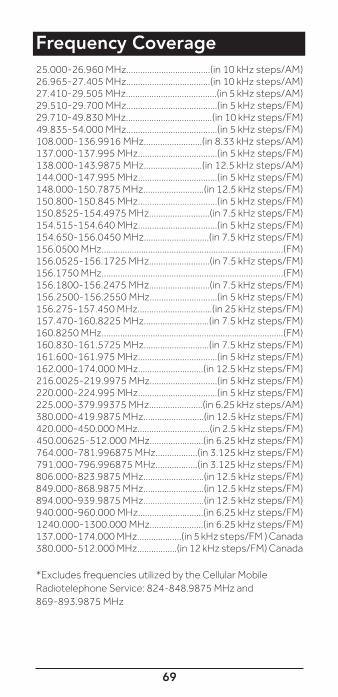
69
Frequency Coverage25.000-26.960 MHz....................................(in 10 kHz steps/AM)26.965-27.405 MHz....................................(in 10 kHz steps/AM)27.410-29.505 MHz.......................................(in 5 kHz steps/AM)29.510-29.700 MHz.......................................(in 5 kHz steps/FM)29.710-49.830 MHz.....................................(in 10 kHz steps/FM)49.835-54.000 MHz.......................................(in 5 kHz steps/FM)108.000-136.9916 MHz.........................(in 8.33 kHz steps/AM)137.000-137.995 MHz..................................(in 5 kHz steps/FM)138.000-143.9875 MHz.........................(in 12.5 kHz steps/AM)144.000-147.995 MHz..................................(in 5 kHz steps/FM)148.000-150.7875 MHz..........................(in 12.5 kHz steps/FM)150.800-150.845 MHz..................................(in 5 kHz steps/FM)150.8525-154.4975 MHz..........................(in 7.5 kHz steps/FM)154.515-154.640 MHz..................................(in 5 kHz steps/FM)154.650-156.0450 MHz............................(in 7.5 kHz steps/FM)156.0500 MHz..............................................................................(FM)156.0525-156.1725 MHz..........................(in 7.5 kHz steps/FM)156.1750 MHz..............................................................................(FM)156.1800-156.2475 MHz..........................(in 7.5 kHz steps/FM)156.2500-156.2550 MHz.............................(in 5 kHz steps/FM)156.275-157.450 MHz................................(in 25 kHz steps/FM)157.470-160.8225 MHz............................(in 7.5 kHz steps/FM)160.8250 MHz..............................................................................(FM)160.830-161.5725 MHz............................(in 7.5 kHz steps/FM)161.600-161.975 MHz..................................(in 5 kHz steps/FM)162.000-174.000 MHz............................(in 12.5 kHz steps/FM)216.0025-219.9975 MHz.............................(in 5 kHz steps/FM)220.000-224.995 MHz..................................(in 5 kHz steps/FM)225.000-379.99375 MHz.......................(in 6.25 kHz steps/AM)380.000-419.9875 MHz..........................(in 12.5 kHz steps/FM)420.000-450.000 MHz...............................(in 2.5 kHz steps/FM)450.00625-512.000 MHz.......................(in 6.25 kHz steps/FM)764.000-781.996875 MHz..................(in 3.125 kHz steps/FM)791.000-796.996875 MHz..................(in 3.125 kHz steps/FM)806.000-823.9875 MHz..........................(in 12.5 kHz steps/FM)849.000-868.9875 MHz..........................(in 12.5 kHz steps/FM)894.000-939.9875 MHz..........................(in 12.5 kHz steps/FM)940.000-960.000 MHz............................(in 6.25 kHz steps/FM)1240.000-1300.000 MHz.......................(in 6.25 kHz steps/FM)137.000-174.000 MHz...................(in 5 kHz steps/FM ) Canada380.000-512.000 MHz.................(in 12 kHz steps/FM) Canada
*Excludes frequencies utilized by the Cellular Mobile Radiotelephone Service: 824-848.9875 MHz and869-893.9875 MHz

70
Consumer WarrantyThis Whistler product is warranted to the original purchaser for a period of one (1) year from the date of original purchase against all defects in materials and workmanship, when purchased from an authorized Whistler retailer. This limited warranty is void if the unit is abused, misused, modified, installed improperly, or if the housing and/or serial numbers have been removed. There are no express warranties covering this product other than those set forth in this warranty. All express or implied warranties for this product are limited to one (1) year. Whistler is not liable for damages arising from the use, misuse, or operation of this product including but not limited to loss of time, inconvenience, loss of use of your product or property damage caused by your product or its failure to work, or any other incidental or consequential damages including personal injury.
DO NOT RETURN ITEM TO STORE WHERE PURCHASED.
FOR WARRANTY INFORMATION, CONTACT WHISTLER CUSTOMER SERVICE AT 1-866-923-8719.
Representatives are available to answer your questions
Monday – Friday
from 8:00 a.m. to 5:00 p.m. CT
71
Service Under WarrantyDuring the warranty period, defective units will be repaired or replaced (with the same or a comparable model), at Whistler’s option, without charge to the purchaser when returned prepaid, with dated proof of purchase to the address below. Units returned without dated proof of purchase will be considered out-of-warranty and therefore are not covered by the described Limited Warranty. (Refer to Service Out-of-Warranty section.
Due to the specialized equipment necessary for testing Whistler products, there are no authorized service centers other than Whistler. When returning a unit for service under warranty, please follow these instructions:
1. Ship the unit in the original carton or in a suitable sturdy equivalent, fully insured, with return receipt requested to:
Whistler Repair Dept.
1412 South 1st St. Rogers, AR. 72756
Please allow 3 weeks turnaround time.
IMPORTANT: Whistler will not assume responsibility for loss or damage incurred in shipping. Therefore, please ship your unit insured with return receipt requested. CODs will not be accepted!
2. Include with your unit the following information, clearly printed:
• Your name and physical street address for shipping (no PO Boxes), a daytime telephone number, and an email address (if applicable).
• A detailed description of the problem (e.g.,“device will not Power ON”).
• A copy of your dated proof of purchase or bill of sale.
3. Be certain your unit is returned with its serial number. Units without serial numbers are not covered under warranty.
IMPORTANT: To validate that your unit is within the warranty period, make sure you keep a copy of your dated proof of purchase. For warranty verification purposes, a copy of your dated store receipt must accompany any Whistler product sent in for warranty work.
72
Service Out-of-WarrantyUnits will be repaired at “out-of-warranty” service rates when:
• The unit’s original warranty has expired.
• A dated proof of purchase is not supplied.
• The unit has been returned without its serial number.
• The unit has been misused, abused, modified, installed improperly, or had its housing removed.
The minimum out-of-warranty service fee for your Whistler Scanner is $120.00 (U.S.). If you require out-of-warranty service, please return your unit as outlined in the section “Service Under Warranty” along with a cashier’s check or money order in the amount of $120.00. Payment may also be made by MasterCard, VISA or American Express. Personal checks are not accepted.
In the event repairs cannot be covered by the minimum service fee, you will be contacted by a Whistler technical service specialist who will outline options available to you.
IMPORTANT: When returning your unit for service, be certain to include a daytime telephone number and an email address (if applicable).
Customer Service
If you have questions concerning the operation of your Whistler product, or require service during or after the warranty period, please call Customer Service at
1-866-923-8719.
Representatives are available to answer your questions Monday - Friday from 8:00 a.m. to 5:00 p.m. (CT) or visit the FAQ at
www.whistlergroup.com.


CORPORATE HEADQUARTERS1716 SW Commerce Dr. Ste. 8PO Box 1760Bentonville, AR 72712Toll Free (800) 531-0004TEL (479) 273-6012 FX (479) 273-2927
www.whistlergroup.com
CUSTOMER RETURN CENTER1412 South 1st St.Rogers, AR 72756Customer Service Tel (866) 923-8719 Email: [email protected]
For US Patent info visit: www.whistlergroup.com/pat
P/N 581008a-TRX106C16 ©2016 The Whistler Group, Inc.