Sequential Synthesis Histo ry: Combinational Logic...
28
MISII Facilities for managing networks of FSMs Sequential Circuit Partitioning Facilities for handling latches SIS Optimization (single machine) Sequential Circuit VIS (handles hierarchy) Original Final Sub ckt 1 Sub ckt N Optimize Verify Partition Combine / Flatten Interface logic (asynchronous?) . . . . partition for layout
Transcript of Sequential Synthesis Histo ry: Combinational Logic...

Sequential Synthesis
History: Combinational Logic ! single FSM ! Hier-
archy of FSM's.
MISII
Facilities for managingnetworks of FSMs
Sequential Circuit
Partitioning
Facilities for handling latches
SIS
Optimization(single machine) Sequential Circuit
VIS (handles hierarchy)
Original Final
Sub ckt 1 Sub ckt NOptimize
Verify
Partition Combine /Flatten
Interface logic(asynchronous?)
. . . .
partition for layout
1

What are Combinational Circuits?
De�nition: A circuit is combinational if it computes
a function which depends only on the inputs applied
to the circuit; for every input value, there is a unique
output value.
� Circuits with an acyclic underlying topology are
combinational.
� Cyclic circuits can be combinational, in fact, there
are combinational circuits whose minimal form must
have cycles [Kautz 1970].
� Recent work on checking if circuit combinational
[Malik'94, Shiple'95]. These are based on X-valued
simulation.
2

What are Sequential Circuits?
� Some sequential circuits have memory elements.
Synchronous circuits have clocked latches. Asyn-
chronous circuits may or may not have latches
(e.g. C-elements), but these are not clocked.
� Feedback (cyclic) is a necessary, but not su�cient
condition for a circuit to be sequential.
� Synthesis of sequential circuits is not as well devel-
oped as combinational. Sequential synthesis tech-
niques not really used in commercial software.
out 1
LatchPresent State Next State
in 1
in 2
in 3
in 4
Prim
ary
Out
put
Prim
ary
Inpu
t
0
1
−−
−−
/1
−−−1/1
(−−
00, 11−0)/0
(1010, 0110)/1
Registers and Latches (Netlist)
State Transition Graph (STG)
The above circuit is sequential since output depends
on the state and input.
3

Representations of Sequential Circuits
ns
pi
ps
ns’
ns’ns
1
2
ns3
1
2
ns’3
ns’n
nsn
out 1
LatchPresent State Next State
in 1
in 2
in 3
in 4
Prim
ary
Out
put
Prim
ary
inpu
tst
0
1
−−−−/1
−−−1/1
(−−00, 11−0)/0
(1010, 0110)/1
Transition Relation
Gates and Latches (Netlist)
State Transition Graph (STG)
� Transition relation is T (pi; ps; ns) or T (pi; ps; ns; po).
It is the characteristic function of all edges of the STG.
T (pi; ps; ns) =Y
(nsi�fi(pii; psi))
� Each representation has its advantages and disad-
vantages. STG is like a two-level description - can
blow up. Netlist only way for large circuits. Transi-
tion T usually represented by BDD's. Can blow up,
but can also express it as separate relations for each
latch which are implicitly conjoined:
T =Y
Ti(pii; psi; nsi)
4

Example - Highway Light (Verilog)
module hwy_control(clk, car_present, enable_hwy,
short_timer, long_timer, hwy_light,
hwy_start_timer, enable_farm);
input clk,car_present,enable_hwy,short_timer,
long_timer;
output hwy_light,hwy_start_timer,enable_farm;
boolean wire car_present;
wire short_timer, long_timer, hwy_start_timer,
enable_farm, enable_hwy;
color reg hwy_light;
initial hwy_light = GREEN;
assign hwy_start_timer = (((hwy_light == GREEN)
&& ((car_present == YES) && long_timer))
||
(hwy_light == RED) && enable_hwy);
assign enable_farm=((hwy_light==YELLOW)&&short_timer);
always @(posedge clk) begin
case (hwy_light)
GREEN: if ((car_present == YES) &&
long_timer) hwy_light = YELLOW;
YELLOW: if (short_timer) hwy_light = RED;
RED: if (enable_hwy) hwy_light = GREEN;
endcase
end
endmodule
5
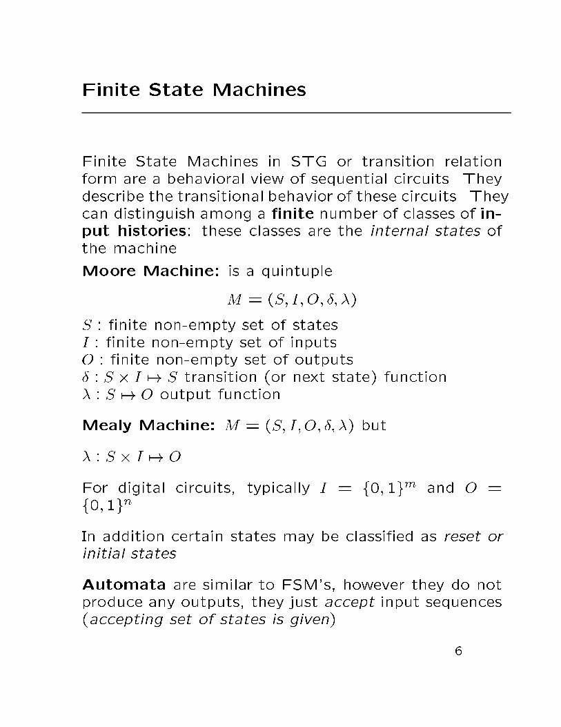
Finite State Machines
Finite State Machines in STG or transition relation
form are a behavioral view of sequential circuits. They
describe the transitional behavior of these circuits. They
can distinguish among a �nite number of classes of in-
put histories: these classes are the internal states of
the machine.
Moore Machine: is a quintuple
M = (S; I; O; �; �)
S : �nite non-empty set of states
I : �nite non-empty set of inputs
O : �nite non-empty set of outputs
� : S � I 7! S transition (or next state) function
� : S 7! O output function
Mealy Machine: M = (S; I;O; �; �) but
� : S � I 7! O
For digital circuits, typically I = f0; 1gm and O =
f0;1gn.
In addition certain states may be classi�ed as reset or
initial states.
Automata are similar to FSM's, however they do not
produce any outputs, they just accept input sequences
(accepting set of states is given).
6

Representing State Machines
State Transition Graphs and Tables
Example: Tra�c Light Controller - Mealy machine
HG
HY
FG
FY
State Transition Graph: Example
PS IN NS OUT
HG c and t1 HY hl = GREEN; fl = RED; st = 1
HG HG hl = GREEN; fl = RED; st = 0
HY not(ts) HY hl = YELLOW; fl = RED; st = 0
HY ts FG hl = YELLOW; fl = RED; st = 1
FG FG hl = RED; fl = GREEN; st = 0
FGnot(not(c) or t1)
FYnot(c) or t1 hl = RED; fl = GREEN; st = 1
FY not(ts) FY hl = RED; fl = YELLOW; st = 0FY ts HG hl = RED; fl = YELLOW; st = 1
State Transition Table: Example
not(c and t1)/hl = GREEN; fl = RED; st = 0
c and t1/hl = GREEN; fl = RED; st = 1
not(ts)/hl = YELLOW; fl = RED; st = 0
ts/hl = YELLOW; fl = RED; st = 1
not(not(c) or t1)/hl = RED; fl = GREEN; st = 0
not(c) or t1/hl = RED; fl = GREEN, st = 1
not(ts)/hl = RED; fl = YELLOW; st = 0
ts/hl = RED; fl = YELLOW; st = 0
not(c and t1)
7

Representing State Machines
� State Transition Graphs and State Transition Ta-
bles are similar; the �rst is graphical, the second
is tabular.
� In this example the edges (transitions) are labeled
with general logic functions (predicates) of the in-
puts.
� Traditionally minterms or cubes have been used for
the transitions (e.g. KISS format), especially for
tables, since used as input to two-level minimizers.
Minterms need the most edges and arbitrary logic
functions (predicates) the least.
8

Transition and Output Relations
R � I � S � S �O is the transition and output relation.
r = (in; sps; sns; out) 2 R if and only if input in causes a
transition from sps to sns and produces output out.
Since R is a set, it can be represented by its charac-
teristic function (and hence as a BDD).
Depending on the application it may be preferable to
keep the transition and output relation separate:
Transition Relation: R� � I � S � S
Output Relation: R� � I � S �O
9

Non-Determinism and Incomplete Speci-�cation
a/0
a/1
s0
s1
s2
� In automata theory, non-determinism is associ-
ated with many transitions; from a given current
state and under the same input conditions we may
go to di�erent states and have di�erent outputs.
Each behavior is considered valid. Nondetermin-
ism provides a compact way to describe a set of
valid behaviors.
� In classical sequential function theory, transition
functions and output functions can be incompletely
speci�ed (i.e. the functions can have don't cares),
i.e. de�ned only on a proper subset of their input
space. Where it is unde�ned, we consider it to
allow any behavior. This also describes a set of
valid behaviors.
10
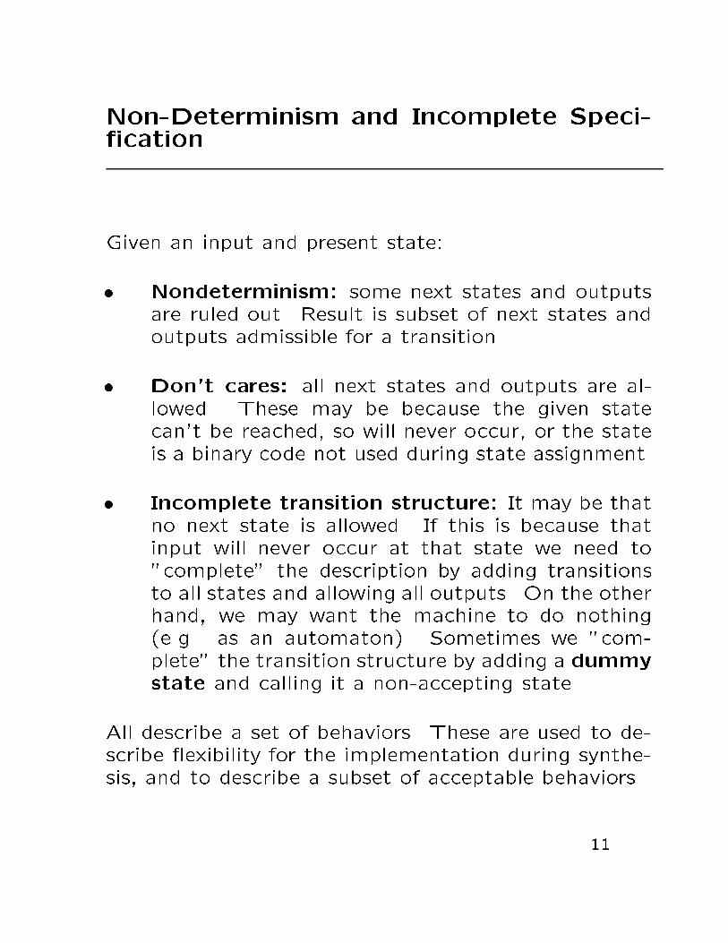
Non-Determinism and Incomplete Speci-�cation
Given an input and present state:
� Nondeterminism: some next states and outputs
are ruled out. Result is subset of next states and
outputs admissible for a transition.
� Don't cares: all next states and outputs are al-
lowed. These may be because the given state
can't be reached, so will never occur, or the state
is a binary code not used during state assignment.
� Incomplete transition structure: It may be that
no next state is allowed. If this is because that
input will never occur at that state we need to
"complete" the description by adding transitions
to all states and allowing all outputs. On the other
hand, we may want the machine to do nothing
(e.g. as an automaton). Sometimes we "com-
plete" the transition structure by adding a dummy
state and calling it a non-accepting state.
All describe a set of behaviors. These are used to de-
scribe exibility for the implementation during synthe-
sis, and to describe a subset of acceptable behaviors.
11

Non-Determinism and Incomplete Speci-�cation
� Optimization tools for logic synthesis and veri�ca-
tion exploit in various fashions incomplete speci�-
cation to achieve optimization objectives.
More recently, methods to exploit exibility given
by non-determinism have been devised [ Kim and
Newborn, Somenzi, Wang, Watanabe, Kam&Villa
]
� At the implementation level, only one of the pos-
sible next states and outputs is chosen (complete
speci�cation).
12

Incompletely Speci�ed Machines
Next state and output functions have don't cares.
However, for an implementation, � and � are func-
tions, thus they are uniquely de�ned for each input
and state combination.
Don't cares arise when some combinations are of no
interest:
� they will not occur or
� their outputs will not be observed.
For these, the next state or output may not be speci-
�ed. (In this case, � and � are relations, but of special
type). (We should make sure we want these as don't
cares). Such machines called incompletely speci�ed.
Example:
s1 s2
1/1
1/−
0/0s1 s2
1/1
1/−
0/0
0/−
−/−d
s1 s2
1/1
1/−
0/00/−
0/−
By adding a dummy state this can be converted to a
machine with only the output incompletely speci�ed.
Could also make "error" as the output when transiting
to the dummy state. Alternately (better), can interpret
unde�ned next state as allowing any next state.
13
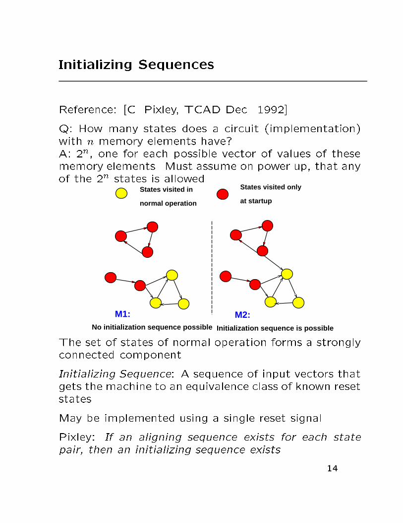
Initializing Sequences
Reference: [C. Pixley, TCAD Dec. 1992]
Q: How many states does a circuit (implementation)
with n memory elements have?
A: 2n, one for each possible vector of values of these
memory elements. Must assume on power up, that any
of the 2n states is allowed.States visited in
normal operation
States visited only
at startup
No initialization sequence possible Initialization sequence is possible
M1: M2:
The set of states of normal operation forms a strongly
connected component.
Initializing Sequence: A sequence of input vectors that
gets the machine to an equivalence class of known reset
states.
May be implemented using a single reset signal.
Pixley: If an aligning sequence exists for each state
pair, then an initializing sequence exists.
14
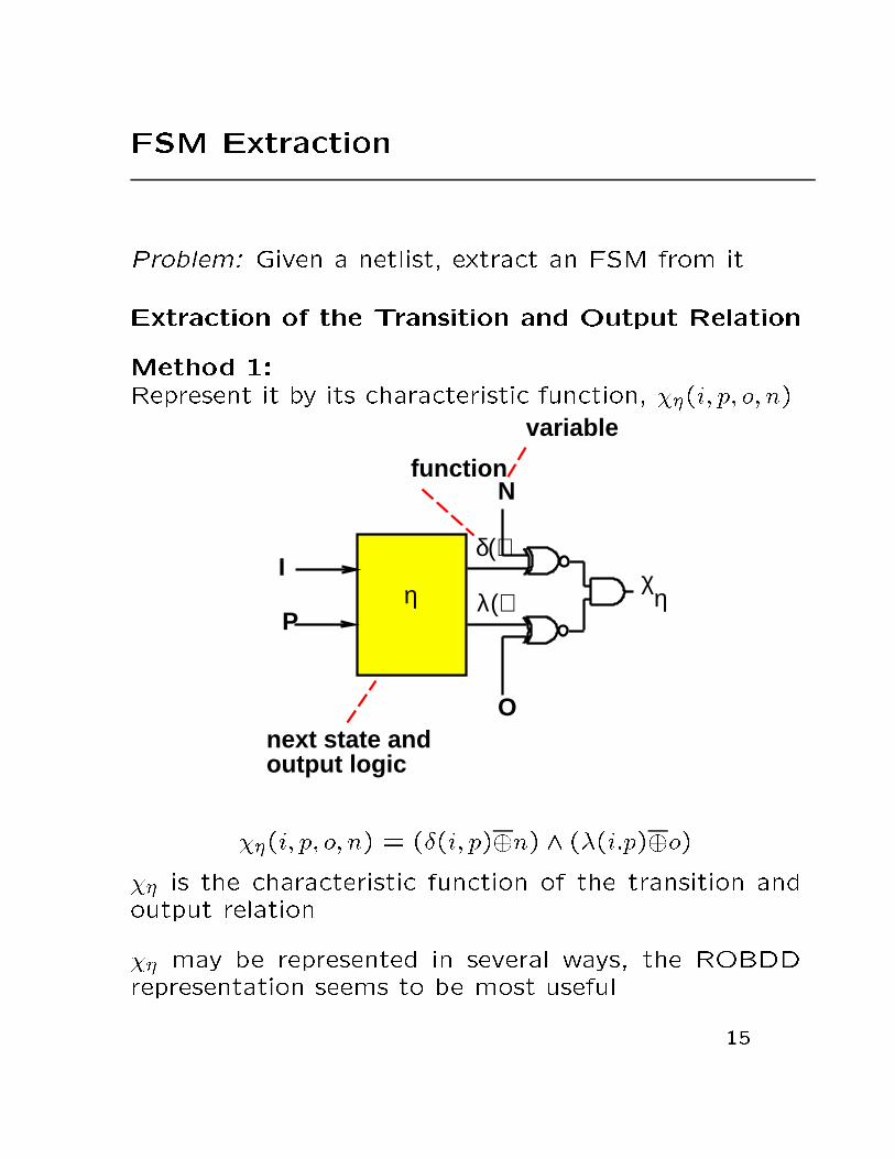
FSM Extraction
Problem: Given a netlist, extract an FSM from it.
Extraction of the Transition and Output Relation
Method 1:
Represent it by its characteristic function, ��(i; p; o; n).
η χI
P
N
O
variable
function
next state and output logic
δ()
λ() η
��(i; p; o; n) = (�(i; p)�n) ^ (�(i:p)�o)
�� is the characteristic function of the transition and
output relation.
�� may be represented in several ways, the ROBDD
representation seems to be most useful.
15

FSM Extraction
Explicit/Semi-Implicit Extraction of all Transitions
Method 1:
Reference: [Devadas-Ma-Newton88]
Visit states starting from the reset states (in breadth-
�rst-order).
extract(C) { /* C is the given circuit */
st_table = { };
list = { };
foreach(s in reset_states)
add_list(list, s);
while((ps = next_unvisited(list)) != NIL) {
/* iterate till all states have been visited */
while([(in, ns, out) <= generate_ns(ps)] != NIL) {
/* generate transitions from ps one by one */
st_table = st_table + {(in, ps, ns, out)};
if(! in_list(list, ns)) add_list(list, ns);
}
mark_visited(list,ps);
}
return(st_table);
}
Of course, could do this in DFS order too, but see next
slide.
16

FSM Extraction
Semi-Implicit Extraction of all Transitions
generate ns(ps):
1. Set present state lines to ps.
2. Select a value for the next state and output lines
(sequentially go through all possibilities).
3. Find input values (possibly none) that will result
in that next state and output value. This need
not be a minterm but may be a cube. Use ATPG
justi�cation techniques to �nd input cube. (How-
ever, must also �nd a cover of input cubes - i.e.
must enumerate all possible edges.)
Semi-Implicit Extraction:
� method is exponential in the number of states.
� May not be possible to represent �� in reasonable
space as a STT.
Implicit Method
� Use BDD's to represent ��.
17
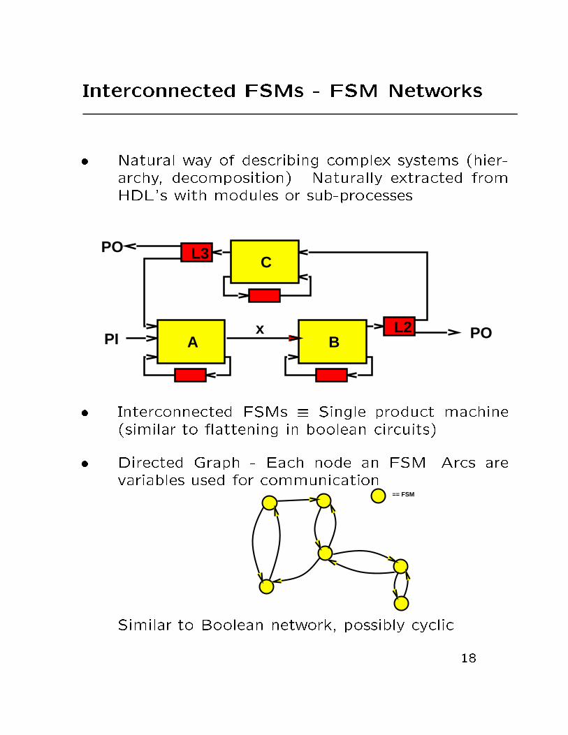
Interconnected FSMs - FSM Networks
� Natural way of describing complex systems (hier-
archy, decomposition). Naturally extracted from
HDL's with modules or sub-processes.
A B
C
PO
PO
PIL2
L3
x
� Interconnected FSMs � Single product machine
(similar to attening in boolean circuits)
� Directed Graph - Each node an FSM. Arcs are
variables used for communication.== FSM
Similar to Boolean network, possibly cyclic.
18

FSM Networks
12
3 4
k
k−1
k−2
Consider k component machines
Mi = (Ii; Si; Oi; �i; �i); i = 1; :::; k
interconnected to form a network of FSMs (or com-
posite machine or decomposed machine)
MN =M1 �M2 � ::: �Mk = (I; SN ; O; �N ; �N):
The state set of MN is SN = S1 � S2 � ::: � SK, and
�N and �N are the next state and output mappings
induced by the properties of the component machines.
MN realizes (or de�nes) the product ( attened or
lumped or composed) machine M = (I; S; O; �; �).
Using BDD's, the transition relation for the product
machine is:
T (I; S;O; S0) =
kY
i=1
Ti(Ii; Si; Oi; S0i)
19

FSM Networks
If we had perfect optimization tools, product machine
is best, however
� product machine is huge (state explosion prob-
lem).
� tools are heuristic (imperfect)
Tools needed for
� synthesis on a network (optimize components sep-
arately, using global information)
� veri�cation on a network (verify network of re-
duced components)
� restructuring FSM networks (decomposition/ attening).
Tools analogous to ones we have for Boolean networks.
Research:
� near-minimal collapsing of networks of FSMs (Wolf,
1991)
� Component minimization.
� VIS development.
20

Near-Minimal Collapsing of FSM Networks
� Collapsing a network of completely speci�ed min-
imized FSMs may create a huge product machine
� If the product machine contains many equivalent
states, a small product FSM may be obtained af-
ter minimization. However intermediate machines
may be too big.
Is it sometimes possible to detect, while collapsing,
most equivalence classes to produce directly a small
product FSM [Wolf, 1991].
� Key observation: network of FSMs have many
equivalences recognizable in a single cycle. If two
states have the same outputs and go to the same
next states, then equivalent.
� A network composed of state-minimized compo-
nent FSM's can still have equivalent product
states because the transitions which make states
in a component distinguishable may not be allowed
in the network (called communication equivalence)
21

Communication Equivalence
M1
M2
t2
t1x1
t3
x2
s1 s2−/w1=1
w1=1/o1=0
−/o1=1
w1 o1
−/o1=0w1=0/o1=1
w1=0/o1=1
w1=1/o1=0
Example:
When M1 in state s1, w1 = 1 and M2 goes to state
t3 (from t1 or t2) with output o1 = 0. Since M1
never outputs w1 = 0, product machine never goes
into states s2 � x1 or s2 � x2. Since x1 and x2 make
t1 and t2 non-equivalent, product states s1 � t1 and
s1� t2 are equivalent.
t1t2 t31/0
Procedure: Use communication equivalences to de-
duce other state equivalences by working backward
one-cycle implications from known equivalences. If two
states have the same outputs and go to the same next
(equivalent) states then equivalent.
Result: Only undetected equivalences are those de-
pendent on nets not visible as primary inputs or primary
outputs.
22

Sequential Input Don't Cares
� Input don't care vectors
A B
C
PO
PO
PIL2
L3
x
Machine A does not output a certain combination l at
x, when B is in set of states Sl. The transitions of B
from states in Sl under input l are therefore unspeci�ed.
Exploited by state minimization and state encoding al-
gorithms.
23

Sequential Input Don't Cares
� Input don't care sequences of vectors
q1
q2
q3
1/01
1/01
1/100/10
0/11
0/00
S1 S2
S3 S4
S5 S6
−0/1
−0/0
−0/111/0
−0/0
11/0 −0/0
−0/1
11/0
01/0
11/1
The sequence (11, 11) is a don’t care.
BA
Suppose that machine A (left) drives machine B (right).
The two outputs of A are the inputs to B. A does not
produce all possible output sequences. For instance,
(11; 11) is don't care input sequence. This implies that
a certain sequence of transitions will not occur in B.
However, note that can't simply remove states in B.
24
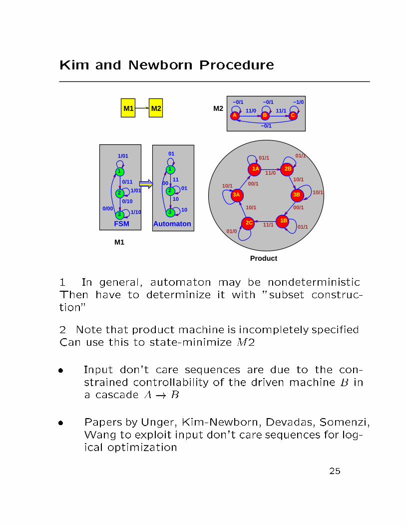
Kim and Newborn Procedure
−0/1
−0/1 −0/1 −1/0
11/0 11/1A B C
1A 2B
3B
1B2C
3A
01/1
11/0
01/1
10/1
10/1
00/1
01/111/101/0
10/1
10/1 00/1
1
2
3
1/01
0/11
1/01
0/10
1/100/00
FSM
01
11
01
10
10
00
1
2
3
Automaton
M1
M2
Product
M1 M2
1. In general, automaton may be nondeterministic.
Then have to determinize it with "subset construc-
tion".
2. Note that product machine is incompletely speci�ed.
Can use this to state-minimize M2.
� Input don't care sequences are due to the con-
strained controllability of the driven machine B in
a cascade A! B.
� Papers by Unger, Kim-Newborn, Devadas, Somenzi,
Wang to exploit input don't care sequences for log-
ical optimization.
25
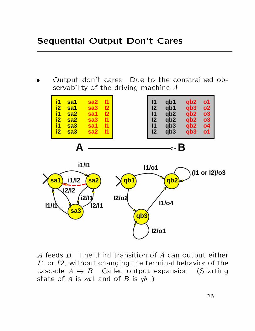
Sequential Output Don't Cares
� Output don't cares. Due to the constrained ob-
servability of the driving machine A.
qb1qb1qb2qb2qb3qb3
qb2qb3qb2qb2qb2qb3
sa1sa1sa2sa2sa3sa3
sa2sa3sa1sa3sa1sa2
i1i2i1i2i1i2
A B
I1I2I2I1I1I1
I1I2I1I2I1I2
o1o2o3o3o4o1
I1/o1
I2/o1
I1/o4I2/o2
i2/I1i2/I1
i1/I1
i1/I2
i1/I1
i2/I2
sa1 sa2
sa3
qb1 qb2
qb3
(I1 or I2)/o3
A feeds B. The third transition of A can output either
I1 or I2, without changing the terminal behavior of the
cascade A ! B. Called output expansion. (Starting
state of A is sa1 and of B is qb1).
26

Sequential Output Don't Cares
� Output expansion produces a multiple-output FSM
in which a transition outputs any element of a sub-
set of symbolic or binary values (rather than any
element of all possible values as in the case of an
unspeci�ed transition).
� Modify state minimization procedures to exploit
output don't cares. In previous example sa2 be-
comes compatible with sa3. One less state after
state minimization (at the beginning both A and
B are individually state minimized).
i2/I1i2/I1
i1/I1
i1/I1
i2/I2
sa1 sa2
sa3
i1/I1sa1 sa23
i1/I1
i2/I1i1/I2
i1/I1
27
Overview of FSM Optimization
� obtain the FSM description
{ provided by the designer as a state table
{ extracted from netlist
{ derived from HDL description
� obtain as a by-product of high-level synthesis
� translate to netlist, extract from netlist
� state minimization Combine equivalent states to
reduce the number of states. For most cases, min-
imizing the states results in smaller logic, though
this is not always true.
� state assignment Assign a unique binary code to
each state. The logic structure depends on the
assignment, thus this needs to be done optimally.
(NOVA, JEDI)
� minimization of a node in an FSM network.
� decomposition of FSM's and/or Collapsing
� sequential redundancy removal using ATPG tech-
niques.
28