Sequence Diagram Generator Presentation II MSE Project / Fall, 2005 Samer AliSaleh Major Advisor:...
30
Sequence Diagram Generator Sequence Diagram Generator Presentation II Presentation II MSE Project / Fall, 2005 MSE Project / Fall, 2005 Samer AliSaleh Samer AliSaleh Major Advisor: Bill Major Advisor: Bill Hankley Hankley
-
Upload
phillip-atkins -
Category
Documents
-
view
215 -
download
1
Transcript of Sequence Diagram Generator Presentation II MSE Project / Fall, 2005 Samer AliSaleh Major Advisor:...

Sequence Diagram Generator Sequence Diagram Generator Presentation IIPresentation II
MSE Project / Fall, 2005MSE Project / Fall, 2005
Samer AliSalehSamer AliSaleh
Major Advisor: Bill HankleyMajor Advisor: Bill Hankley

Presentation I Action ItemsPresentation I Action Items
Quality Assurance Plan.Quality Assurance Plan. Area covered by formal Area covered by formal
specification .specification . Technical Inspectors.Technical Inspectors. Better GUI Prototype.Better GUI Prototype. Used TechnologyUsed Technology

Action Item: Quality Assurance PlanAction Item: Quality Assurance Plan
Quality assurance plan is created Quality assurance plan is created and can be found on the and can be found on the following link:following link:
http://www.cis.ksu.edu/~ssaleh/mseproject.htmhttp://www.cis.ksu.edu/~ssaleh/mseproject.htm

Action Item: Formal Specification TopicAction Item: Formal Specification Topic
The Analyzer Rules were The Analyzer Rules were selected for formalization using selected for formalization using OCL.OCL.
More details about the More details about the specification in the following specification in the following slides.slides.

Action Item: Technical InspectorsAction Item: Technical Inspectors
Judy Dizon (MSE)Judy Dizon (MSE) Patrcik Gallagher (MSE)Patrcik Gallagher (MSE)
Inspection will be done during Inspection will be done during phase 3 of the project.phase 3 of the project.
Inspection List can be found on Inspection List can be found on the following link:the following link:
http://http://www.cis.ksu.edu/~ssaleh/mseproject.htmwww.cis.ksu.edu/~ssaleh/mseproject.htm

Action Item: GUI PrototypeAction Item: GUI Prototype
Problem:Problem: Only Visio GUI Only Visio GUI diagrams were provided as a diagrams were provided as a prototype. No Executable GUI.prototype. No Executable GUI.
Solution:Solution: an executable prototype an executable prototype is built with some functionality of is built with some functionality of each given requirement.each given requirement.
Prototype demonstration will be Prototype demonstration will be given at the end, with an example.given at the end, with an example.

Action Item: Used TechnologyAction Item: Used Technology
Writing Plug-in for Smart Writing Plug-in for Smart Development Environment Development Environment (SDE) developed by Visual (SDE) developed by Visual ParadigmParadigm

Smart Development EnvironmentSmart Development Environment
Very powerful tool that has the Very powerful tool that has the needed functionality to fit any needed functionality to fit any applicationapplication
Can be extended and integrated Can be extended and integrated through different IDEs.through different IDEs.
Easier to write plug-in: Readable Easier to write plug-in: Readable tutorial, and well organized API.tutorial, and well organized API.
Functionality Vs. Development TimeFunctionality Vs. Development Time Online SupportOnline Support
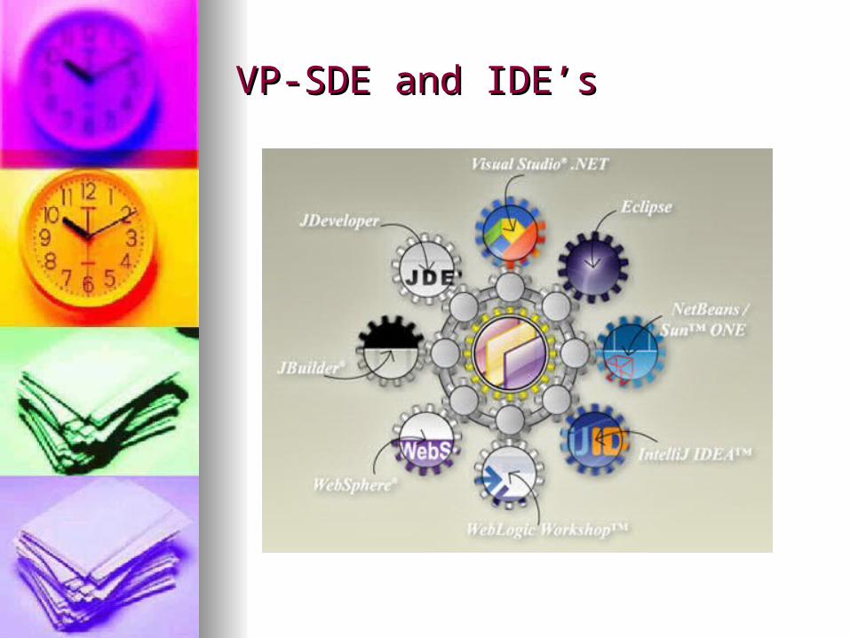
VP-SDE and IDE’sVP-SDE and IDE’s

VP-SDE Plug-in ArchitectureVP-SDE Plug-in Architecture
Plugins
SeqDaigramGenerator
Plugin.xml Plugin.properties
icons
src
classes
Compile/Save
Plugin Architecture
VP-UML API
Transfer Action
Respond to Action

Writing Plug-in Challenges….Writing Plug-in Challenges….
Learning Curve:Learning Curve:- Very brief tutorial.- Very brief tutorial.
- Uncommented API. - Uncommented API. Click hereClick here Limited Interaction: Limited Interaction: - No listeners nor Events handling or - No listeners nor Events handling or
processing.processing. Bugs in the APIBugs in the API
- Bugs even in getters & setters- Bugs even in getters & setters No way to debug or trace exceptionsNo way to debug or trace exceptions

Design Architecture -Package ModelDesign Architecture -Package Model
Actions Handler
Dialogs
Controller
Diagram Elements Models
UML Diagrams SDE Diagram Manager

Design Arch. – Class ModelDesign Arch. – Class Model
Click HereClick Here to view the class to view the class diagram.diagram.

Design Arch.- Controller Design Arch.- Controller Domain modelDomain model

Design Arch. – Analyzer Design Arch. – Analyzer Domain ModelDomain Model
SequenceDiagGenerator
+determineValidCalleeClasses()+createClassIndirectAssociation(in allAssociations[] : IRelationshipEnd)+generateIndirectAssociations(in assocFromEnd : IModelElement, in assocToEnd : IModelElement)+createNewIndirectAssociation(in fromEnd, in toEnd, in intermediateClassName : string, in intermediateClassId : string)+checkIfClassHasDirectRelation(in calleeClass : IModelElementFactory)+colorCalleeClassBlue(in calleeShape : IShapeUIModel)+colorCalleeClassGray(in calleeShape : IShapeUIModel)
seqDiagGeneratorAnalyzer
+getFromEnd() : IModelElement+getToEnd() : IModelElement
AnalyzerClassIndirectAssociation
1
*
+getFillColor()
IShapeUIModel
+getEndRelationship() : IEndRelationship+getModelElement()+getOppositeEnd() : IRelationshipEnd
IRelationshipEnd
+getAggregationKind() : string
IAssociationEnd
+getFromEnd() : IRelationshipEnd+getToEnd() : IRelationshipEnd
IEndRelationship

Design Arch.- Sequence Diagram Design Arch.- Sequence Diagram (Create New Sequence Diagram)(Create New Sequence Diagram)
DesignerPlugin_API ::ActionStartGeneration
click on toolbar icon
perform(action)
::SequenceDiagGenerator
showNewSeqDiagramDialog
:SequenceDiagramGraphics
showNewSeqDiagramDialog
NewSeqDiagDialog
new
OK(seqName,actorName)
creatNewSequenceDiagram(seqName,actorName)
createNewSeqDiagram()
seqDiagram
new
createSeqActorElement

Design Arch. – Sequence DiagramDesign Arch. – Sequence Diagram(Create New Caller )(Create New Caller )
DesignerPlugin_API
rightClick:SelectNewCaller
showSeqDiagramCallerDialog(selectedClass)
:SequenceDiagGenerator :SequenceDiagramGraphics
showSeqDiagramCallerDialog(selectClass)
:NewSeqDiagElementDialog
new
OK(newLifeLineName)
createSeqDiagramElement(lifeLineName)
createNewCallerElement(name)
createNewSeqLifeLineElement(callerName,selectedModel)
cleanSequenceDiagram()

Design Arch. – Sequence DiagramDesign Arch. – Sequence Diagram(Create New Callee )(Create New Callee )
DesignerPlugin_API
rightClick:SelectNewCallee
showSeqDiagramCalleeDialog(selectedClass)
:SequenceDiagGenerator :SequenceDiagramGraphics
showSeqDiagramCalleeDialog(selectClass)
:NewSeqDiagElementDialog
new
OK(newLifeLineName)
createSeqDiagramElement(lifeLineName)
createNewCalleeMessageElement(name)
createNewSeqLifeLineElement(callerName,selectedModel)
createSeqDiagramNewMessage(currentCaller,currentCallee,selectedModel)
cleanSequenceDiagram()

Design Arch.- Sequence DiagramDesign Arch.- Sequence Diagram(Create New Life Line Element)(Create New Life Line Element)
:SequenceDiagramGraphics :IModelElementFactory
:IDiagramElement
:IInteractionLifeLine
instance()
createInteractionLifeLine()
new
return:newLifeLine
setName(name)
setBaseClassifier(selectedClass)
:DiagramManager
createDiagramElement( sequenceDiagram, lifeLine )
new
return:lifeLineDiagramElement
setLocation(x,y)
setNewLifeLineLocation()
createNewSeqLifeLineElement(callerName,selectedMo
del)

Design Arch. – State ModelDesign Arch. – State Model(Sequence Diagram Generator)(Sequence Diagram Generator)

Formal SpecificationFormal Specification
Analyzer Part + Related Classes Analyzer Part + Related Classes & Attributes.& Attributes.
9 Classes and 13 associations9 Classes and 13 associations 3 major invariants.3 major invariants. Formal Specification is done Formal Specification is done
using OCL and USE 2.3.0.using OCL and USE 2.3.0.

Formal Specification Sample 1Formal Specification Sample 1
class IClass < IModelElement
Attributes
classID:String
className:String
Operations
getAllFromEndAggregationsAndCompositionsToClasses():Set(IClass)=self.classFromAssociationEnd-> select (a|a.type=#AGGREGRATIONKIND_AGGREGATION or a.type=#AGGREGATIONKIND_COMPOSITED).toClass->asSet
// This operation is used to generate the transitive aggregation set for a
// given class For example if A aggregate to B and B Aggregate to C
// then the operation for class A will generate the set {B,C} transitiveAggregation(s:Set(IClass)):Set(IClass)=
if s-> includesAll (s.getAllFromEndAggregationsAndCompositionsToClasses())then s
else transitiveAggregation(s-> union (s.getAllFromEndAggregationsAndCompositionsToClasses())->asSet)
Endif
end
Return all the classes that the selected class has aggregation with
If Selected class aggragation classes is
Subset ofTransitive_Set , return Transitive_Set
ElseRecursion(Transitive_Set U Aggregation_Classes)

Formal Specification Sample 2Formal Specification Sample 2//3--If Message corresponds to indirect Association and intermediate classes exist, then the sender // object / must have a reference to receiver object either by a pre outgoing message with a return // type of receiver or by an ingoing message with a parameter passes as receiver.context message:IMessageinv senderHasReferenceOfReceiverForIndirectASsociation://Check if the message corresponds to indirect Associationmessage.fromEnd.baseClass.classFromAssociationEnd->select(a|a.toClass->includes(message.toEnd.baseClass))->isEmptyAndmessage.fromEnd.baseClass.allFromClassRelationship->select(r|r.relationToClass->includes(message.toEnd.baseClass))->isEmptyAndmessage.fromEnd.baseClass.transitiveAggregation(message.fromEnd.baseClass.getAllFromEndAggregationsAndCompositionsToClasses())->includes(message.toEnd.baseClass)Implies// If Message corresponds to indirect association then check // if there is a pre message in which:message.sequenceDiagram.associatedMessages->exists(m| message.index<m.index and ( // 1.a pre message sender is the same as current message sender and // the return type of the message is the same as the class name (m.fromEnd = message.fromEnd and m.toEnd.baseClass.classOperations->select (op|op.name = message.name).returnType->asSet->includes(message.toEnd.name)) or //1.b pre messate receiver is the same as the current message sender and //the message has at least one parameter of type of current messate receiver. (m.toEnd = message.fromEnd and m.toEnd.baseClass.classOperations->exists (op|op.operationParameters.type->asSet->includes(message.toEnd.name)) )))
Message Ends don’t have aggregation
Message Ends don’t have association
Message Ends have indirect relation
Exists a message with a return type of receiver
going from sender
Exists a message going into sender with a
parameter passed as type of receiver

Testing PlanTesting Plan
Functional Testing.Functional Testing. Test case for each functional Test case for each functional
requirement.requirement. ~ 80 test cases.~ 80 test cases. Testing will be done as part of Testing will be done as part of
the assessment evaluation in the assessment evaluation in phase 3 of the project.phase 3 of the project.
Testing PlanTesting Plan
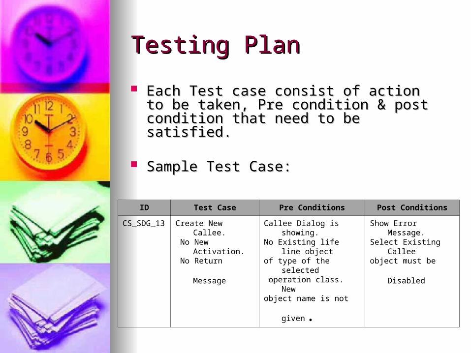
Each Test case consist of action to be Each Test case consist of action to be taken, Pre condition & post condition that taken, Pre condition & post condition that need to be satisfied.need to be satisfied.
Sample Test Case:Sample Test Case:
IDID Test Case Pre Conditions Post Conditions
CS_SDG_13 Create New Callee. No New Activation.
No Return Message
Callee Dialog is showing. No Existing life line objectof type of the selected operation class. New
object name is not given.
Show Error Message. Select Existing Callee
object must be Disabled

Project Plan & Cost EstimateProject Plan & Cost Estimate
COCOMO Model was used to COCOMO Model was used to estimate LOC, and Time.estimate LOC, and Time.
Unadjusted FP = 68Unadjusted FP = 68 Adjusted FP = 65.96 Adjusted FP = 65.96 Estimated SLOC = 2506Estimated SLOC = 2506 Estimated Development Time = 5 Estimated Development Time = 5
monthsmonths
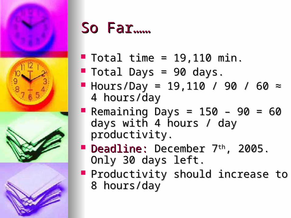
So Far……So Far……
Total time = 19,110 min.Total time = 19,110 min. Total Days = 90 days.Total Days = 90 days. Hours/Day = 19,110 / 90 / 60 ≈ 4 Hours/Day = 19,110 / 90 / 60 ≈ 4
hours/dayhours/day Remaining Days = 150 – 90 = 60 days Remaining Days = 150 – 90 = 60 days
with 4 hours / day productivity.with 4 hours / day productivity. Deadline:Deadline: December 7 December 7thth, 2005. Only 30 , 2005. Only 30
days left.days left. Productivity should increase to 8 Productivity should increase to 8
hours/dayhours/day
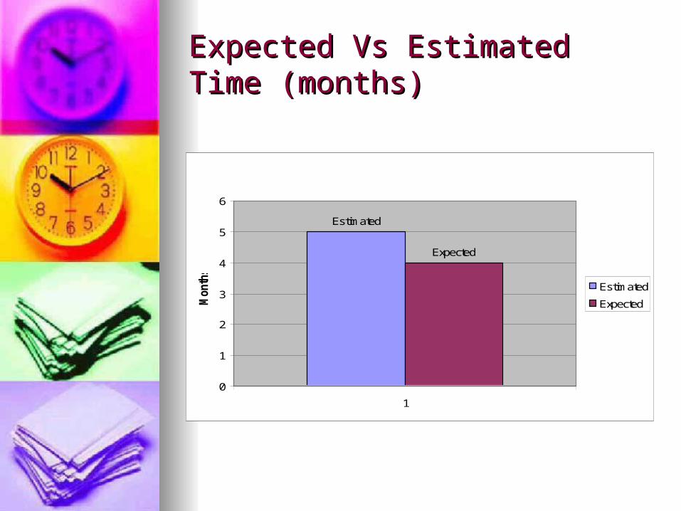
Expected Vs Estimated Time Expected Vs Estimated Time (months)(months)
Estimated
Expected
0
1
2
3
4
5
6
1
Month
s
Estimated
Expected

Current Vs Estimated LOCCurrent Vs Estimated LOC
Estimated, 2506
Current, 2000
0
500
1000
1500
2000
2500
3000
1
LO
C Estimated
Current

ProductivityProductivity
phase 1, 3
phase2, 4
phase3, 8
0
1
2
3
4
5
6
7
8
9
1
Pro
duct
ivity phase 1
phase2
phase3