September 28, 2017 - Ardaman & Associates Inc … · · 2017-10-03Presentation Back in June 2016...
59
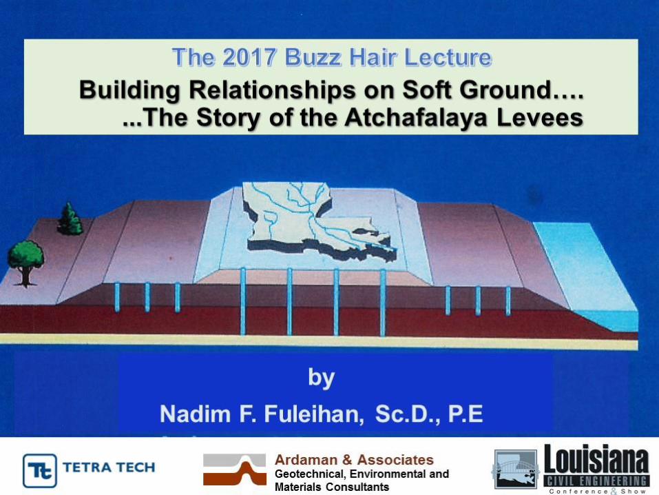
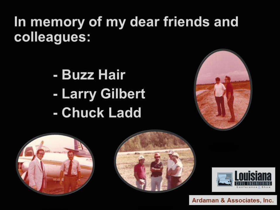
- 1 - September 28, 2017 2017 LA Civil Eng’g Conference & Show (ASCE & ACI) Charles W. “Buzz” Hair, III Lecture Building Relationships on Soft Ground…The Story of the Atchafalaya Levees by Nadim F. Fuleihan, Sc.D., P.E. President, Ardaman & Associates, Inc. Abstract If only the Atchafalaya levees could talk, they would tell us that it all began in the alluvial and deltaic plains of South Central Louisiana. The flood protection levees contributed to the professional development of many students who converged to MIT in the mid-1970’s from various corners of the world, and where we developed an affinity for soft ground construction. Through that venue, technical challenges were overcome and strong relationships were built amongst and between MIT scholars and researchers and the USACE (NOD). That is where I first met and interacted with Louisiana’s own Buzz Hair and Larry Gilbert, and our relationship, initially founded on soft ground, flourished and strengthened over the years. Chuck Ladd’s SHANSEP design methodology was successfully used for developing construction alternatives for raising the levees using staged construction, stability berms and vertical sand drains…but the story of the Atchafalaya levees also extends to other constructed facilities. For example, the levees could lay claim to benefits realized by extrapolating findings from instrumented test sections to optimize the storage life of waste disposal facilities constructed on soft ground. The levees have in fact bestowed on many of us the ability to analyze, tackle and solve other difficult problems. This lecture is dedicated to the memory of my colleague Charles W. Hair, III and my friend and associate Dr. Lawrence W. Gilbert Sr. Presentation Back in June 2016, Larry Gilbert asked me if I would consider giving the Buzz Hair Lecture (at the Annual ASCE Fall Conference in New Orleans). Larry, Buzz and I had been classmates at MIT. Larry reminded me that Buzz’s master thesis was on the “Design of Levees with Sand Drains.” He then added that soft ground construction and the Atchafalaya Levees would be an appropriate topic (Slide 1), and made me “promise not to get into recounting our late night escapade with Lester, a famous football player turned bar owner in Morgan City.” Memories of events spanning a 45-year period of my life flashed in front of me...The Story of the Atchafalaya Levees was unfolding, and it had to be told: "Building Relationships on Soft Ground…” The story is dedicated to the memory of my dear friends and colleagues (Slide 2) Buzz Hair, Larry Gilbert and Chuck Ladd (photos circa early to mid-seventies showing Buzz with Chuck, Larry and I at the Bayou Sorrel levee, and Chuck with Lou Cappozzoli who took us on a levee tour in his private plane). "It All Began...in the Atchafalaya River Basin"...in Cajun Country (Slide 3)...in south central Louisiana. The flood protection levees in question are located along the east edge of the Atchafalaya Basin (Slide 4). These levees are necessary to the Gulf Intercoastal Navigation System and to protect life and property. They contain flood waters from the Red and Atchafalaya Rivers, and can, if need be, collect flood waters diverted from the Mississippi. Major construction difficulties were encountered, particularly in the southern portion of the east Atchafalaya Basin near Morgan City at the location (delineated in red and) referred to as Bayou Sorrel. Some 10 miles
Transcript of September 28, 2017 - Ardaman & Associates Inc … · · 2017-10-03Presentation Back in June 2016...

- 1 -
September 28, 2017 2017 LA Civil Eng’g Conference & Show (ASCE & ACI)
Charles W. “Buzz” Hair, III Lecture
Building Relationships on Soft Ground…The Story of the Atchafalaya Levees by
Nadim F. Fuleihan, Sc.D., P.E. President, Ardaman & Associates, Inc.
Abstract If only the Atchafalaya levees could talk, they would tell us that it all began in the alluvial and deltaic plains of South Central Louisiana. The flood protection levees contributed to the professional development of many students who converged to MIT in the mid-1970’s from various corners of the world, and where we developed an affinity for soft ground construction. Through that venue, technical challenges were overcome and strong relationships were built amongst and between MIT scholars and researchers and the USACE (NOD). That is where I first met and interacted with Louisiana’s own Buzz Hair and Larry Gilbert, and our relationship, initially founded on soft ground, flourished and strengthened over the years. Chuck Ladd’s SHANSEP design methodology was successfully used for developing construction alternatives for raising the levees using staged construction, stability berms and vertical sand drains…but the story of the Atchafalaya levees also extends to other constructed facilities. For example, the levees could lay claim to benefits realized by extrapolating findings from instrumented test sections to optimize the storage life of waste disposal facilities constructed on soft ground. The levees have in fact bestowed on many of us the ability to analyze, tackle and solve other difficult problems. This lecture is dedicated to the memory of my colleague Charles W. Hair, III and my friend and associate Dr. Lawrence W. Gilbert Sr. Presentation Back in June 2016, Larry Gilbert asked me if I would consider giving the Buzz Hair Lecture (at the Annual ASCE Fall Conference in New Orleans). Larry, Buzz and I had been classmates at MIT. Larry reminded me that Buzz’s master thesis was on the “Design of Levees with Sand Drains.” He then added that soft ground construction and the Atchafalaya Levees would be an appropriate topic (Slide 1), and made me “promise not to get into recounting our late night escapade with Lester, a famous football player turned bar owner in Morgan City.” Memories of events spanning a 45-year period of my life flashed in front of me...The Story of the Atchafalaya Levees was unfolding, and it had to be told: "Building Relationships on Soft Ground…” The story is dedicated to the memory of my dear friends and colleagues (Slide 2) Buzz Hair, Larry Gilbert and Chuck Ladd (photos circa early to mid-seventies showing Buzz with Chuck, Larry and I at the Bayou Sorrel levee, and Chuck with Lou Cappozzoli who took us on a levee tour in his private plane). "It All Began...in the Atchafalaya River Basin"...in Cajun Country (Slide 3)...in south central Louisiana. The flood protection levees in question are located along the east edge of the Atchafalaya Basin (Slide 4). These levees are necessary to the Gulf Intercoastal Navigation System and to protect life and property. They contain flood waters from the Red and Atchafalaya Rivers, and can, if need be, collect flood waters diverted from the Mississippi. Major construction difficulties were encountered, particularly in the southern portion of the east Atchafalaya Basin near Morgan City at the location (delineated in red and) referred to as Bayou Sorrel. Some 10 miles

- 2 -
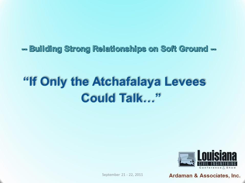
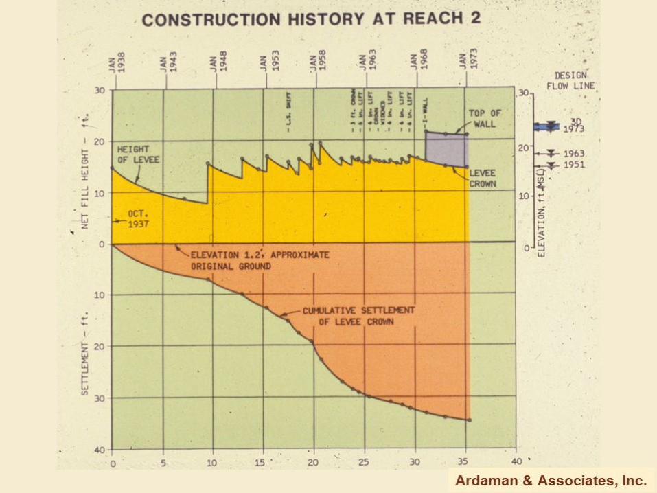
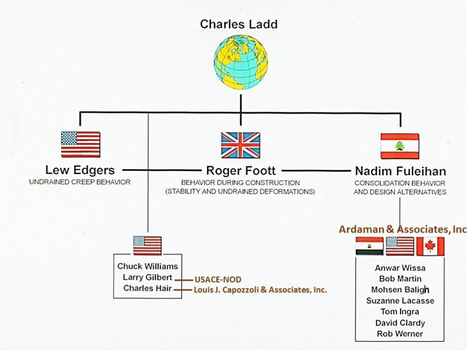
north of this site, test sections had been constructed in the mid-sixties. These test sections were extensively analyzed by the USACE, and at MIT under the direction of Professor Charles C. Ladd. “If Only the Atchafalaya Levees could talk…” was the title I had originally chosen (Slide 5); with Larry’s passing I thought it would also be appropriate to talk about building strong relationships on soft ground....Yet if the Atchafalaya Levees could talk (Slide 6), they would first lay claim to... "some of the softest geologic deposits...and terribly poor foundation conditions..." The alluvial and deltaic plains of south central Louisiana were formed in a backswamp environment during periods when the Mississippi River overflowed its banks. The uppermost deposits consist of a 100-foot thick layer of soft and very plastic clays of low shear strength and high compressibility, with an average plasticity index on the order of 75% (Slide 7). Profiles of natural moisture content, total unit weight, maximum past pressure and undrained strength (from cone penetrometer soundings) (Slide 8) reveal the presence of a near surface 20-foot thick layer of highly organic clays, as evidenced by increased water contents and decreased unit weights. The normally consolidated soft clay deposits of particular interest (with undrained shear strengths as low as 100 psf) extend to a depth of 55 feet where a desiccated crust is encountered, as evidenced by increased maximum past pressures and cone penetration resistance. The poor foundation conditions in the Atchafalaya Basin hampered construction progress since the mid-thirties. Excessive settlements made it impossible to achieve design grades in many areas even after more than 40 years (Slide 9). Long-term settlements, partly due to consolidation and particularly due to undrained creep, were especially important. Numerous attempts to raise the levee crest to a net height of about 13 feet resulted in cumulative levee crown settlements on the order of 19 feet along one levee reach at Bayou Sorrel, and by as much as 34 feet along another reach (Slide 10). By the mid-1970’s, with continued settlement, and with continued upward revisions to the design flow line due to channel-siltation, the levees had to be raised even further. If the Atchafalaya Levees could talk (Slide 11)...they would take credit for…”the professional development of a number of engineers from the US Army Corps NOD and WES…” Some of you would recognize (Slide 12) Rodney Picciola, Gerry Satterlee, Bill Caver and Richard Pinner, successive Chiefs of the Geotech Branch at the NOD, as well as Frank Weaver and Larry Cave from WES. Larry Gilbert, Bill Gwyn and Pete Cali were all intimately involved in the levee evaluations; and to the USACE credit, many of these Corps Engineers later took leadership roles in some of the best geotechnical consulting engineering firms like Gore, Ardaman, Eustis and Sea Level Engineering. I should point out that Larry Gilbert, Jay Joseph, Pete Cali and Francisco Duarte were the designated successive USACE Contracting Officer Representatives on a related contract that was awarded to Ardaman. If the Atchafalaya Levees could talk (Slide 13)...they would also take credit for…”the professional development of a number of students who converged to MIT from various corners of the world…" Chuck Ladd (who sits on top of the levee world –Slide 14) had been successful in convincing the U.S. Corps of Engineers to sponsor the levee research work and was advisor to three doctoral and several master’s students. When I came to MIT in 1971, Roger Foott and Lew Edgers were actively pursuing their respective doctoral research programs. Roger was busy modeling and predicting the behavior of the levee test sections during construction, while Lew was concentrating on the long-term undrained creep behavior of the levees. Chuck Williams, Larry Gilbert and Buzz Hair obtained their master’s degrees working on other aspects of levee performance. Larry came to MIT from the US Army Corps and Buzz from Louis J. Cappozzoli & Associates…..My doctoral research first concentrated on predicting the consolidation behavior of the levee test sections. I was then given the opportunity to apply the design methodology that had been developed at MIT to evaluate construction alternatives for raising the levees. The results were promising. So when I joined Ardaman & Associates in 1976, the USCE, NOD, awarded us a contract to develop and implement a construction alternative for one of the levee reaches at Bayou Sorrel. Chuck Ladd was retained as a consultant. Mohsen Baligh and Suzanne Lacasse worked on the project during a summer

- 3 -
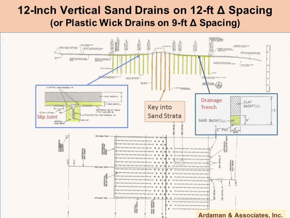
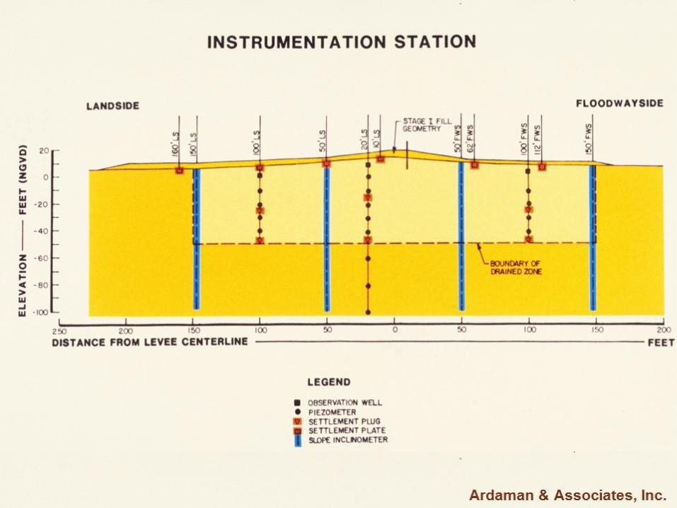
recess. Anwar Wissa and Bob Martin, and MIT students Tom Ingra, Dave Clardy and Rob Werner worked on the project in various roles. After taking Chuck Ladd's courses, I developed an affinity to soft ground construction. As a new student at MIT, I was quite fascinated by the factor of safety contours (Slide 15) for the differing failure modes that needed to be taken into account: levee-berm; levee-bank; and berm-bank failure surfaces...I was impressed by the good correlation (Slide 16) developed between highly stressed or yielded zones and critical failure surfaces... So I gravitated towards the levees...If the Atchafalaya Levees could talk (Slide 17)...they would take at least partial credit for..."validating and refining Chuck Ladd's SHANSEP design methodology..." Chuck Ladd, on the other hand, would probably say it with a slightly different twist. Chuck is more likely to say: "If SHANSEP could talk...it would take at least partial credit for...enabling the Atchafalaya Flood Protection Levees to be raised..." In any case, the Ladd & Foott (1974) SHANSEP (i.e., Stress History and Normalized Soil Engineering Properties) design methodology was successfully used in developing construction alternatives for raising the levees at Bayou Sorrel. The design alternative employed staged construction, stability berms and vertical sand drains. In spite of the very poor foundation conditions at the Bayou Sorrel site, a marked increase in undrained strength (Slide 18) can be noted at the levee centerline compared to the shear strength at the distant landside and floodwayside offsets. (This was partly due to consolidation under loads imposed by earlier construction and partly due to soft soil displacement and replacement by settled fill.) A three-stage construction alternative (Slide 19) with stability berms was developed after optimizing the fill geometry based on extensive stability, undrained deformation and consolidation analyses (for a 2500-foot long levee reach). A 300-foot wide drained zone was selected in order to minimize undrained creep deformations, and promote consolidation and corresponding increases in shear strength during the first two filling stages. 12-inch diameter vertical sand drains (and plastic wick drains) were installed in the drained zone using a triangular spacing of 12 feet (and 9 feet respectively). Stage I construction resulted in the application of about 4.5 feet of fill to the landside berm and 3.5 feet of fill to the floodwayside berm. The levee crest was raised from Elevation 14 feet (MSL) to Elevation 19 feet (MSL). It was subsequently raised to Elevation 22 feet (MSL) and 24 feet (MSL) during Stages II and III, respectively, once the foundation clays in the drained zone had achieved 80% consolidation under prior stages of filling. The sheet-pile floodwall was raised during Stage III to Elevation 29 feet (MSL), a practice that has been curtailed but that successfully survived the Katrina fury at the Bayou Sorrel levee. There were some unique features to the vertical drain system in this type application (Slide 20). First, it was important to prevent transmission of hydraulic pressures at high river levels from the floodwayside to the landside, so the drains beneath the centerline levee were isolated and extended downward into a deep subsurface sand stratum. Moreover, because sand borrow was not readily available nearby, 6-inch wide drainage trenches were used beneath the berms in lieu of a drainage blanket. Water from each vertical drain was collected in a slotted 11/4-inch PVC pipe connected to a 1-inch PVC outlet pipe with slip-joints to accommodate projected settlements. Undrained circular arc total stress stability analyses indicated that the Stage I construction would have a factor of safety on the order of 1.3 towards the landside (which is the critical side during flooding), and about 1.15 towards the floodwayside (Slide 21). Instrumented stations were located 300 feet apart and incorporated slope inclinometers at varying offsets (Slide 22), settlement plates and settlement plugs, and a network of piezometers at varying depths and offsets. Predictions based on finite element analyses indicated undrained end-of-construction settlements (t=t1) and lateral movements during Stage I filling of less than 0.5 feet (Slide 23), as shown by the predicted settlement profile and as illustrated by the projected magnitude of lateral movements. Long-term undrained creep settlements (t=10 t1) were predicted to be insignificant in contrast to as much as several feet of movement documented during prior performance at Bayou Sorrel and at the levee

- 4 -
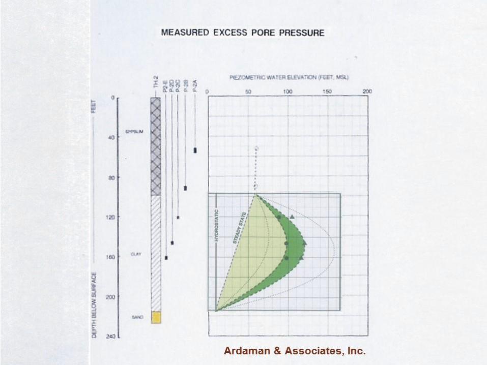
test sections. Measured undrained deformations confirmed the predicted behavior. Total lateral movements of less than 4 inches actually occurred through Stage II. Measured end-of-construction surface settlements during Stage I (Slide 24) were in excellent agreement with predictions as shown by comparing the settlement profiles in the upper graph. The lower graph compares measured surface settlements some one year after construction to predicted settlements, based on a rather optimistic design coefficient of consolidation, ch, of 0.15 ft2/day. Although the deformation patterns are similar, measured settlements were generally less than predicted. Comparison of the progress of consolidation settlement at the levee centerline to theoretical curves (Slide 25) indicated in situ ch; values ranging from 0.05 to 0.15 ft2/day. A gross average ch, value on the order of 0.08 ft2/day was backfigured from both pore pressure dissipation and settlement data, during construction Stages I and II. This value is more than twice the cv value determined from oedometer tests, and about one-half the previously selected ch design value. Slightly lower factors of safety on the order of 1.1 to 1.2 were used during Stage II construction (Slide 26) because Stage I had already successfully proof-tested the site as well as the prediction methodology. The Stage III end-of-construction factors of safety (Slide 27) were significantly greater, i.e., 1.4 to 1.6 towards the landside and 1.2 to 1.4 towards the floodwayside. Total long-term levee crest settlements at Bayou Sorrel (Slide 28) were measured and projected to be on the order of 6.6 feet for Stages I through III of the construction alternative. It should be noted, however, that for a net increase in fill height of 10 feet at the end of construction, the total levee crest post-construction settlement 20 years after construction was on the order of 2 feet. If the Atchafalaya Levees could talk (Slide 29)...they would lay claim to... "the benefits realized by extrapolating findings from instrumented test sections...to design and construct waste disposal facilities on soft ground." This photograph (Slide 30) depicts a phosphogypsum stack on the west bank of the Mississippi River in Southeast Louisiana. Phosphogypsum is a by-product generated by fertilizer plants producing concentrated phosphate and other crop nutrient products. The phosphogypsum is traditionally transported in slurry form and stored in a stack which is gradually and systematically raised using the upstream method of construction. In this method, sedimented gypsum is periodically excavated from within the perimeter of the disposal area and cast onto previously sedimented gypsum to raise the perimeter dike and provide additional storage capacity. Water stored atop the stack and entrained within the pores of the sedimented gypsum is acidic (pH on, the order of 1.5 to 2.0) and contains high concentrations of inorganic constituents. Three separate consulting firms (including Ardaman & Associates) were retained by the owner of this facility to independently optimize its storage life. Our recommended growth plan used SHANSEP and relied on the gain in strength from prior consolidation (Slide 31). The storage life that we projected was significantly greater (by 4 to 5 years) than recommended by the other two consultants. A comprehensive field exploration program consisting of undisturbed sampling, core penetrometer soundings, piezometers and slope inclinometers was implemented. Here's a typical example of measured pore pressure dissipation data beneath the stack (Slide 32) that were relied upon to update undrained shear strengths in the soft foundation clays. Lateral movements were regularly monitored as the stack was being raised (Slide 33), in accordance with the observational method, and the rate of movement was checked weekly for any indication of a potentially critical condition. The stack did achieve its recommended maximum design height without any problem. At another nearby facility, the measured distribution of excess pore pressures versus depth (Slide 34) was used to determine the inflection point representing a transition from downward seepage relief and upward seepage flow, at several instrumented piezometer stations. A calibrated seepage model (Slide 35) was then used to document that the excess pore pressures in the foundation clays were creating an effective hydraulic barrier controlling downward migration of leachate from the facility.

- 5 -
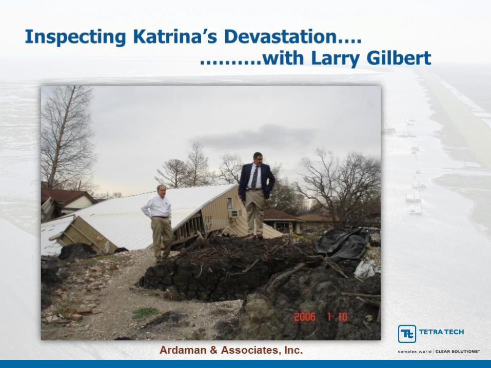
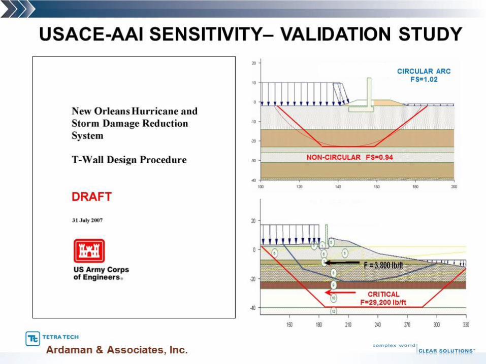
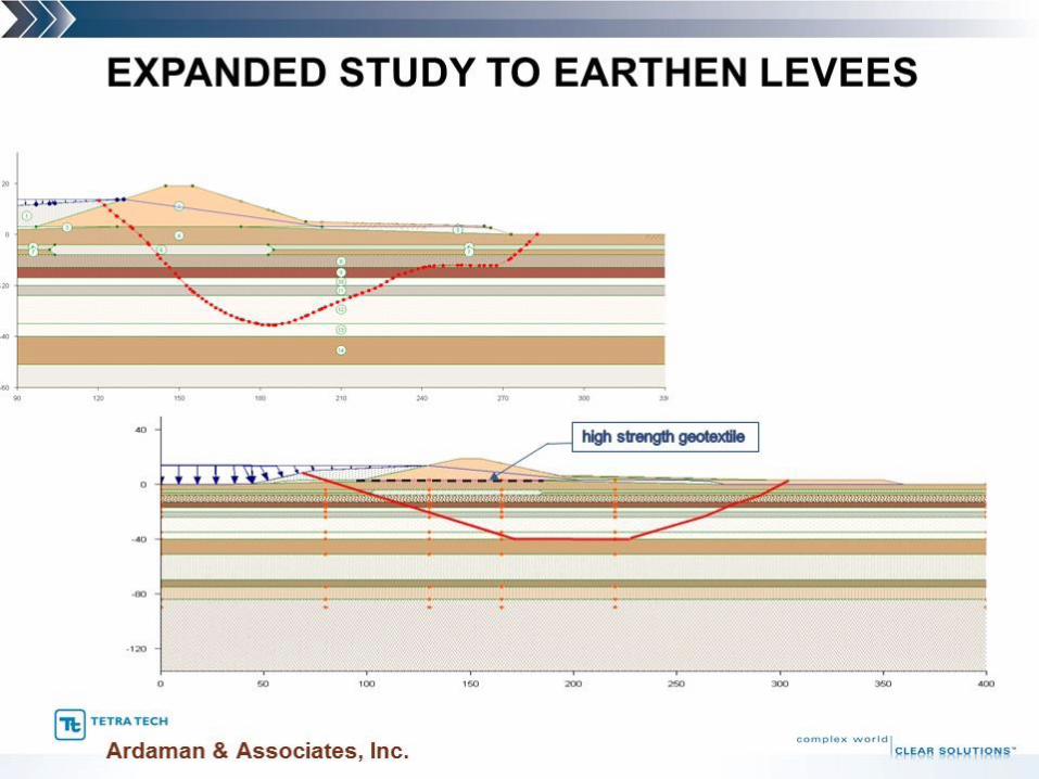
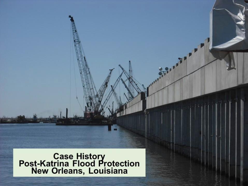
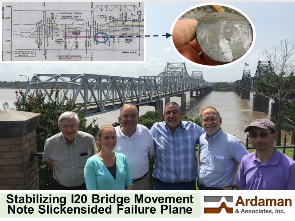
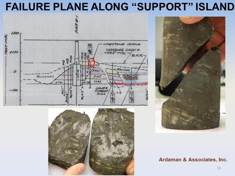
This other case history is from a similar type facility constructed on stiff (rather than soft) clays on the bank of the Houston Ship Channel in Texas (Slide 36). The stack had been raised slightly steeper and some 5 feet higher than had been recommended based on effective stress stability analyses. A characteristic sliding block failure occurred when the stack was 100 feet high. The slope moved 10 to 20 feet outward at which point water retained atop the stack drained through the large cracks on both sides of the failure wedge. As indicated by measured maximum past pressures and estimated effective stresses in the foundation beneath the crest of the stack (Slide 37), the stiff clays had become normally consolidated under the weight imposed by the stack. Ardaman & Associates was retained by the Owner to forensically study the failure and provide recommendations for future growth. (Steve Vick and Chuck Williams were also retained as independent third party reviewers.) Post-mortem stability analyses (Slide 38) yielded an effective stress factor of safety of on the order of 1.03; and a total stress factor of safety using SHANSEP undrained strengths on the order of 0.99. Undrained total stress analyses were the controlling mechanism for evaluating stability at greater heights. The rate of consolidation and corresponding increases in undrained strength were carefully monitored as the stack was raised (Slide 39). A 200-foot setback was implemented and SHANSEP and the observational method used to provide as much as 10 years of additional storage life (Slide 40). And those of us who Built Relationships on Soft Ground would give the Levees Credit not only for our soft ground construction experience (Slide 41), but also our ability to analyze, tackle, and solve difficult problems; the incentive to persevere, to get personally involved, to interact with other team members, and to take charge when needed. I was very touched when Larry Gilbert guided me through the 17th street levee canal failure and the devastation caused by Katrina (Slide 42). Both Larry and I were so proud in our Rob Werner’s lead role in validating and refining the USACE post-Katrina T-Wall design procedure (Slides 43 & 44) and in expanding the improved design methodology to earthen levees (Slide 45). Ardaman (through our parent company Tetra Tech) also had an opportunity to work on the IHNC (Inner Harbor Navigation Canal) Floodwall and Gates (Slide 46). Of particular interest are the shear strengths selected for the tie-in between the T-Wall and MRGO (Mississippi River Gulf Outlet) levee reaches (Slide 47). As shown, the selected (lower bound) design profile based on FV, CPT and SHANSEP strengths (in green & blue) was significantly higher than would have been chosen based on more conventional U and UU test data (in red). The levees could also take credit for stabilizing the I20 Bridge over the Mississippi River in Vicksburg, which connects the Mississippi bluff to the Louisiana plains (Slide 48). The adjacent US-80 Railroad Bridge had experienced significant movements and pier failures since the late twenties whenever the water level in the Mississippi dropped below Stage 10 on the Vicksburg gage (El 56 ft, NGVD). There are 3 sliding blocks contributing to movement from the Mississippi side along the I20 bridge axis, but also in a transverse direction which is of greater concern. One of these blocks encompasses a nearby casino, the other block on the opposite side of the bridge access ramp abuts a scour hole within the river bed, and the third block encompasses both the US-80 relatively shallow piles and I-20 bridge deeper pier caissons which actually act as anchors restricting excessive movement of adjacent more unstable blocks. In 2009, Ardaman was retained by the LADOTD and FHWA to remediate the problem and we relied on a team of in-house and outside experts including some geo-legends like Dr. Anwar Wissa (blue blazer), Professor Ladd (in red), Bill Marcuson (far right of ASCE & USACE fame-USACE Geotechnical & Structural Lab-ERDC) and Ardaman’s Larry Gilbert, Rob Werner and I. The team also included (Slide 49) Jim Mitchell, another geo-legend (far left), and Professor Hashash (far right-2014 Peck Lecturer). Megan Bourgeois, Larry Gilbert, Bill Marcuson and I are featured in the middle. A thorough field exploration program confirmed that we were dealing with a slickensided failure plane just above the base of the massive bridge pier foundations in a smectite layer that exhibited an extremely low residual friction angle on the order of 6 degrees. (Note that there is an island in the middle of the river which we were originally hoping to use as a failure wedge stabilizing anchor.) The slickensided failure plane was similarly very well defined along the US-80 bridge axis (Slide 50). We were, nevertheless, surprised when we found out that the island itself exhibited inclined slickensided failure planes suggestive of movements from the island towards the

- 6 -
main river bed (Slide 51). The solution that was finally adopted was based on extensive 2D & 3D Stability and PLAXIS type analyses, and extensive evaluation of a wide-spectrum of deformation and pore pressure instrumentation data. This cross section (Slide 52) is taken along the scour hole which has already been filled in a controlled manner so as to stabilize the bluff without adversely impacting the stability of the island. This remedial measure has significantly controlled transverse movements across the bridge towards the scour hole. The other remedial measures which are in the planning stages include: (i) diverting runoff from the bluff away from the bridge and installing drains to lower the water table; and (ii) stabilizing the island and main failure wedges by installing a series of embedded drilled piers intercepting the ancient failure plane along the island. In closing, allow me to read to you the following quote from Theodore Roosevelt (Slide 53) which I believe applies to many of those who built relationships on soft ground, and which I find quite appropriate on this occasion honoring Buzz Hair’s and Larry Gilbert’s memory:
"The credit belongs to the man who is actually in the arena; whose face is marred by dust and sweat and blood; who strives violently;... who knows the great enthusiasms...who spends himself in a worthy cause; who, at the best, knows in the end the triumph of high achievements; and who, at the worst, if he falls at least falls while daring greatly."
References Edgers, L., Ladd, C.C. and Christian, J.T. (1973), “Undrained Creep of Atchafalaya Levee Foundation Clays”. MIT
Dept. of Civil Eng’g., R73-16, SO 319. Fuleihan, N.F. and Ladd, C.C. (1976), “Design and Performance of Atchafalaya Flood Control Levees”. MIT Dept.
of Civil Eng’g., R76-24, SO 543. Fisk, H.N., Kolb, C.R. and Wilbert, L.J. (1952), “Geological Investigation of the Atchafalaya Basin and the Problem
of Mississippi River Diversion”, U.S. Army Engineer Waterways Experiment Station, Vicksburg, Mississippi. Foott, R. and Ladd, C.C. (1972), “Prediction of End of Construction Undrained Deformations of Atchafalaya Levee
Foundation Clays”, MIT Dept. of Civil Eng’g., R72-27, SO 305. Foott, R. and Ladd, C.C. (1973), “The Behavior of Atchafalaya Test Embankments During Construction”, MIT Dept.
of Civil Eng’g., R73-27, SO 322. Gilbert, L.W. (1974), “A Probabilistic Analysis of Embankment Stability Problems”, MIT Dept. of Civil Eng’g., S.M.
Thesis. Hair, C.W. (1974), “Design of Atchafalaya Levees with Vertical Drains”, MIT Dept. of Civil Eng’g., S.M. Thesis. Kaufman, R.I. and Weaver, F.J. (1967), “Stability of Atchafalaya Levees”, ASCE, JSMFD, Vol. 93, SM4, pp 157-
176. Kolb, C.R. and Shockley, W.G. (1959), “Engineering Geology of the Mississippi Valley”, ASCE Transactions, Vol.
124, pp 633-645. Krinitzsky, E.L. and Smith, F.L. (1969), “Geology of Backswamp Deposits in the Atchafalaya Basin, Louisiana”, U.S.
Army Engineers Waterways Experiment Station, Vicksburg, Mississippi, Technical Report S-69-8. Ladd, C.C., Williams, C.E., Connell D.H. and Edgers, L. (1972) “Engineering Properties of Soft Foundation Clays at
Two South Louisiana Levee Sites”, MIT Dept. of Civil Eng’g., R72-26, SO 304. Ladd, C.C., and Foott, R. (1974), “New Design Procedure for Stability of Soft Clays”, ASCE, JGED, Vol. 100, GT7,
pp763-786.