Separator Design for Liquid Removal from Gas Streams · Separator Design for Liquid Removal from...
37
PDHonline Course K134 (3 PDH) Separator Design for Liquid Removal from Gas Streams Instructor: John Pietranski P.E., Ph.D. 2012 PDH Online | PDH Center 5272 Meadow Estates Drive Fairfax, VA 22030-6658 Phone & Fax: 703-988-0088 www.PDHonline.org www.PDHcenter.com An Approved Continuing Education Provider
Transcript of Separator Design for Liquid Removal from Gas Streams · Separator Design for Liquid Removal from...

PDHonline Course K134 (3 PDH)
Separator Design for Liquid Removal from Gas Streams
Instructor: John Pietranski P.E., Ph.D.
2012
PDH Online | PDH Center
5272 Meadow Estates Drive Fairfax, VA 22030-6658
Phone & Fax: 703-988-0088 www.PDHonline.org www.PDHcenter.com
An Approved Continuing Education Provider
www.PDHcenter.com PDHonline Course K134 www.PDHonline.org
© John Pietranski Page 2 of 37
Separator Design for Liquid Removal from Gas Streams
John Pietranski P.E., Ph.D.
Background This course provides a step-by-step development for the design of two types of liquid-in-gas separation devices: horizontal and the vertical gravity separators. These two types of process vessels are utilized throughout the chemical process industry to remove liquids from vapor streams. Gases and liquids are intentionally contacted in several process unit operations: absorption, cooling, mixing, and distillation. While separation of the liquid from the gas stream can and will occur naturally, the rate that this takes place is usually uneconomical or unacceptable. Separation design has been developed that takes theory and empirical methodology to define cause-and-effect parameters. The parameters can be used so that required aspects of desired separation can be determined. In particular and where desired, acceleration of the liquid from gas separation can be designed to occur. This course will focus on deriving the general Application Equations used for calculating key sizing requirements for removing entrained liquids from gas streams. In particular horizontal and vertical gravity separators will be discussed. The equipment requirement is based on a relationship of the gas stream properties as well as the liquid characteristics. Following the calculation development for separation several Application Equation derivations are presented from the open literature. These correlations define the methodology for calculating the size of separation vessels based on specific stream data and desired results for both horizontal and vertical gravity separators. In order to discuss the subject of separation design it will be necessary to define the various terms and descriptions used to characterize liquids in gas streams. In particular, particle size will be discussed relative to the design limits covered by this course. As stated earlier, gas and liquid contacting can occur in the chemical process industry via several mechanisms or processes. Table 1 is a brief listing of several of those types of unit operation activities that can generate liquids in gas streams. The table also gives an indication of the liquid droplet size that can be generated. Note
www.PDHcenter.com PDHonline Course K134 www.PDHonline.org
© John Pietranski Page 3 of 37
that the droplet size unit of measure is the micron, as noted by the micro-meter, µm, designation. This list is not all-inclusive, and is shown so as to give a range of values that liquid droplets can be found in gas streams as well as the process origin for those droplets. In the calculations for liquid droplet removal from gas streams, this course will require to identify, characterize, and estimate properties of the liquid droplet. Figure 1 is another source of information that summarizes the required characteristics for liquid and also solid particles. In this course it will be assumed that the term droplet and particle size can be used interchangeably while our focus is on liquid droplets only. A discussion concerning other types of particles is outside the scope of this course. In Figure 1, the X-axis has the independent variable particle or droplet diameter, again expressed in microns. Along the Y-axis there are nine information bands that relate to the droplet size, or diameter in microns. Again, for this course, the focus will be on spherical liquid droplets. The nine informational bands, along with relevant course comments, are listed below and reading from top to bottom is:
1. Equivalent size. Supplied as general information and not covered in the course.
2. Electromagnetic waves. Supplied as general information and not covered in the course.
3. Technical definitions. Supplied as general information and not covered in the course.
4. Common atmospheric dispersions. Covered in the course examples as characterized by droplet diameters for “mist” and “rain”.
5. Typical particles and gas dispersions. Supplied as general information and not covered in the course.
6. Methods for particle size analysis. Supplied as general information and covered in the course by being “visible to the eye”.
7. Types of gas cleaning equipment. Supplied as general information and covered in the course by gravity settling equipment.
8. Terminal gravitational settling. Supplied as general information and covered in the course for other specific gravities. The liquid and gas stream properties used in this course can differ from air and water.
9. Particle diffusion coefficient. Supplied as general information and covered in the course for other fluids. The values used in this course will be based on the fluids selected and can differ from air and water.
This figure is a good representation for understanding the specific area covered by this course as well as the rest of the areas of particle capture outside the scope of this course. It also introduces the student to several terms that are the basis for this

www.PDHcenter.com PDHonline Course K134 www.PDHonline.org
© John Pietranski Page 4 of 37
course in liquid removal from gas streams. The first term that has been introduced is droplet size and its unit of measurement, the micron. A second term used in this course, as found in the fourth informational band is the characterization of a range of droplet size. For example, when characterizing a process stream that is exiting a vent stack, an observation might be that the gas stream contains liquid droplets that look like “rain”. While not a true quantitative measurement, the qualitative determination is useful. Using the fourth band in Figure 1, the droplet diameter could be assumed to be in the 600 to 10,000 micron range. Likewise for an observation that states it is acceptable if it were more like a fine “mist” tends to qualify the droplet size in the 70 to 200 micron range. The third term used in this course relates to the type of equipment that is included in the Application Equation development, and that is settling chambers. Another expression used in the process industry for this type of equipment is the gravity settling chamber. The gravity settling chamber is a typically a vessel that has been designed so that liquid droplets that enter in with the gas stream undergo a physical change that allows the force of gravity to cause them to drop-out from the gas stream. As the droplets leave the gas stream they deposit and collect at the bottom of the settling vessel and are removed as a liquid stream. It should be noted that the course content is solely on physical removal via gravity of liquid droplets from gas streams. The removal of liquid droplets from a gas stream by condensation or other related mechanisms is not covered in this course. The key term in this course was referred to in the preceding paragraph when the droplet was said to “undergo a physical change that allows the force of gravity to cause them to drop-out from the gas stream”. The key term is the terminal settling velocity or drop-out velocity. This is defined as the velocity, typically in feet per second, at which the liquid droplet will not remain in the gas stream and will fall out due to the force of gravity. This course is focused on determination of the droplet terminal velocity and its effect on gravity separation. The eighth informational band on Figure 1 is useful, but again is relevant only to the particle/fluid conditions specified. This course will develop the detailed expression that has been simplified in this band. Likewise the particle diffusion coefficient, or as it is also called, the “drag coefficient” in the ninth informational band is of interest, but only for the specified stream and particle conditions. This course will cover calculation and typical values for relevant droplet drag coefficients. Another more generic chart that relates particle diameter to classification and removal equipment is provided in Figure 2. The X-axis has the range of particle size diameter in microns. The Y-axis for this figure has only two informational bands: particle classification and removal equipment. This figure focuses on the area of this course. Note that gravity settling chambers are typically used for removal of droplet diameters in the 100 to 10,000+ micron range.

www.PDHcenter.com PDHonline Course K134 www.PDHonline.org
© John Pietranski Page 5 of 37
The key term in this course was referred to several paragraphs back when the droplet was said to “undergo a physical change that allows the force of gravity to cause them to drop-out from the gas stream”. The key term is the terminal settling velocity or drop-out velocity. This is defined as the velocity, typically in feet per second, at which the liquid droplet will not remain in the gas stream and will fall out due to the force of gravity. This physical phenomenon will be referred to in this course as the collection mechanism for gravity liquid-gas separation. This mechanism will be covered along with its effect on separation equipment. Gravity separation relationships will be developed from Stoke’s and Newton’s laws and will utilize stream properties and liquid droplet size to relate settling velocity to removal requirements. In 1851 George Gabriel Stokes derived an expression, now known as Stoke’s Law. Consider a particle that is falling in a gravitational field in which other particles in the field do not hinder it as in Figure 6. Take for example a round pebble being thrown into a deep lake. As the pebble falls it velocity increases and will continue to increase until the accelerating (gravity) and resisting (friction) forces are equal. When this point is reached the particle velocity remains constant during the remainder of its fall unless the balance of forces is upset. The ultimate constant velocity is referred to as the settling or terminal velocity, Vterm. To derive an expression that related the terminal velocity to a spherical shape several familiar expressions are used. The area, Sarea, of a sphere as projected normal to flow is given by:
Sarea = π Dp2/4 (1)
where Dp = droplet diameter. The mass, Mmass, of a sphere is given by:
Mmass = (π Dp3/6) ρp (2)
where ρp = droplet density. For a constant velocity the change with time, θ, can be expressed as:
dVterm/dθ = 0 (3) The forces acting on a falling body are the external forces FE, a buoyant force FB and a drag force due to friction FD. With the overall momentum balance being:
(FE – FD – FB) g = m dV/dθ (4) where m = mass of the body.

www.PDHcenter.com PDHonline Course K134 www.PDHonline.org
© John Pietranski Page 6 of 37
From Newton’s Law the external force FE may be written as:
FE g = m aE (5) where
aE is the acceleration force. The drag force from friction can be expressed as:
FD g = (CD Vfs ρ S) / 2 (6) where
ρ is the fluid density. Vfs is the velocity of the particle relative to the fluid.
Via the Archimedes’ principle the buoyant force relationship becomes:
FB g = (m/ρs) ρ aE. (7) If the external force is gravity, the aE is equal to the acceleration of gravity, g. Then substitution and simplification yields the application equation for terminal, or settling, velocity of falling spheres and is referred to as Newton’s Law:
Vterm = [(4(ρs-ρ) g Dp) / (3 CD ρ)] 0.5 (8)
For turbulent droplet flow, the droplet Reynold’s number must be greater than 1.0 according to:
NRe = (Dp V ρ) / µ (9) where V, ρ, µ are gas stream properties. Dp is the particle diameter. And CD is calculated as:
Log CD = -2 log NRe + log [4 g Dp3 ρ (ρs-ρ)/3µ2] (10)
For the student interested in the derivation of the terminal velocity equation for gravity settling see Chapter 22 in reference # 23.
www.PDHcenter.com PDHonline Course K134 www.PDHonline.org
© John Pietranski Page 7 of 37
Horizontal Gravity Separators
Two excellent sizing procedures have been developed in the open literature for horizontal separators. The first is the procedure published by the American Institute of Chemical Engineers, (AIChE), through their Center for Chemical Process Safety (CCPS) group. The procedure can be found in chapter 5 of technical reference #10. The second procedure is published through the American Petroleum Institute, (API), as ANSI/API Standard 521 and can be found in Section 7 of technical reference #8.
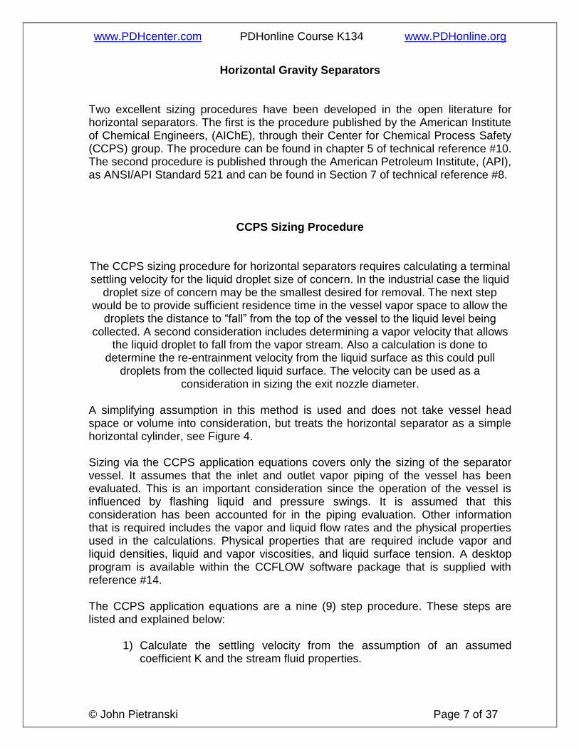
CCPS Sizing Procedure
The CCPS sizing procedure for horizontal separators requires calculating a terminal settling velocity for the liquid droplet size of concern. In the industrial case the liquid
droplet size of concern may be the smallest desired for removal. The next step would be to provide sufficient residence time in the vessel vapor space to allow the
droplets the distance to “fall” from the top of the vessel to the liquid level being collected. A second consideration includes determining a vapor velocity that allows
the liquid droplet to fall from the vapor stream. Also a calculation is done to determine the re-entrainment velocity from the liquid surface as this could pull
droplets from the collected liquid surface. The velocity can be used as a consideration in sizing the exit nozzle diameter.
A simplifying assumption in this method is used and does not take vessel head space or volume into consideration, but treats the horizontal separator as a simple horizontal cylinder, see Figure 4. Sizing via the CCPS application equations covers only the sizing of the separator vessel. It assumes that the inlet and outlet vapor piping of the vessel has been evaluated. This is an important consideration since the operation of the vessel is influenced by flashing liquid and pressure swings. It is assumed that this consideration has been accounted for in the piping evaluation. Other information that is required includes the vapor and liquid flow rates and the physical properties used in the calculations. Physical properties that are required include vapor and liquid densities, liquid and vapor viscosities, and liquid surface tension. A desktop program is available within the CCFLOW software package that is supplied with reference #14. The CCPS application equations are a nine (9) step procedure. These steps are listed and explained below:
1) Calculate the settling velocity from the assumption of an assumed coefficient K and the stream fluid properties.

www.PDHcenter.com PDHonline Course K134 www.PDHonline.org
© John Pietranski Page 8 of 37
Ut = K [(ρliq/ρgas) -1] 0.5 (11) where Ut = terminal settling or drop out velocity in ft/sec. K = terminal velocity constant; 0.27 ft/sec. ρliq = liquid phase density in lb/cu-ft. ρgas = vapor phase density in lb/cu-ft.
In actuality, this is a good starting design decision point. Theoretically, all of the droplets should disengage from the vapor stream at this point. In order to assure the design has the vapor velocity significantly below the settling velocity, we can build in a design factor by adjusting the vapor velocity approach to the dropout velocity using this approach. Let Vdf = a selected safety factor percent from 0 to 100%. The Vapor velocity used for vessel design would then be:
Ut design = Ut * Vdf (12) If we choose 100%, the design velocity reverts back to the theoretical dropout velocity. If we choose 0, we have a “zero” velocity required or an infinitely sized vessel. Initially, use an assumption of 50% and review the vessel diameter and height. The design factor can be adjusted as required based on process knowledge. A good rule of thumb is given in reference #14. For separation design that does not include an outlet mist eliminator nor inlet impingement baffle, the design factor can be as low as 15%. This will cause a much larger vessel. Separation design that includes an exit mist eliminator and inlet impingement baffle can use a design factor of 100%. This will minimize vessel size. It should be noted that the process design based on droplet size distribution and separator purpose will dictate mist eliminator and inlet baffle use.
2) Calculate the limiting axial vapor velocity to prevent entrainment from the separator liquid level surface.
Ue = [R1 * R2 * R3] 0.1 (13)
where Ue = limiting vapor phase velocity to avoid liquid entrainment in ft/sec. σ = liquid surface tension in lb/sec2. g = local acceleration of gravity as 32.2 ft/sec2. µliq = liquid viscosity in lb/ft-sec. R1 = ρliq/ρgas.
R2 = (σ/ρgas) 4.
R3 = [g (ρliq – ρgas) / µliq] 2
3) Assume an average liquid fill level. Convert this to liquid level fraction, y. A starting point is y = 0.5,

www.PDHcenter.com PDHonline Course K134 www.PDHonline.org
© John Pietranski Page 9 of 37
where y = liquid level fraction, hf/D. Hf = depth of liquid in separator. D = diameter of separator in ft.
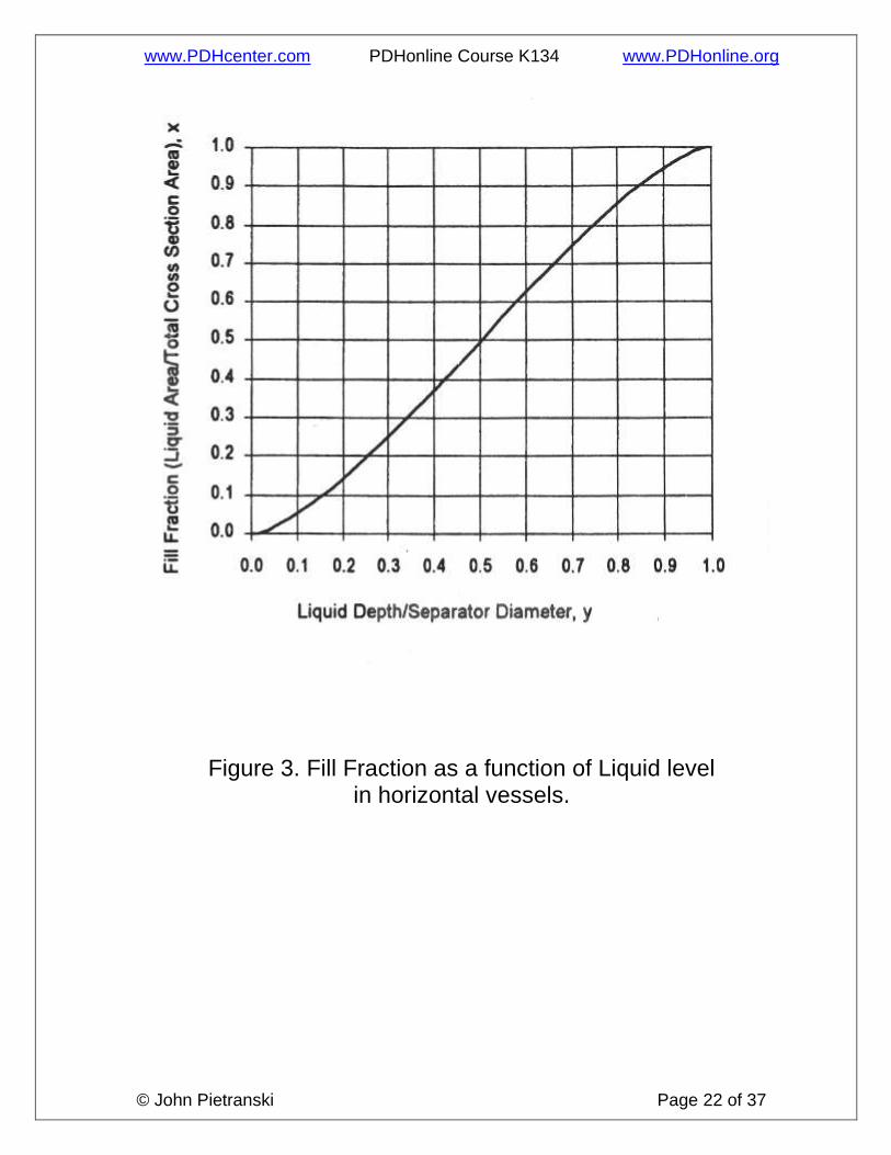
4) Either calculate using equation 14a or read from a chart, similar to Figure 3, the fill fraction, x, or ratio of cross sectional area occupied by the liquid as a ratio of the total vessel cross sectional area.
X = 1/π cos-1 (1 – 2 y) – 2/π (1 - 2 y) (y – y 2) 0.5 (14a)
where
X = fill fraction, as the ratio of cross sectional area occupied by liquid divided by the total vessel cross sectional area, Aliq/Atotal.
y = liquid level fraction, hf/D. Aliq = cross sectional area of separator occupied by liquid in sq-ft. Atotal = total cross sectional area of separator in sq-ft.
X = 4Q gas / (π D2L) (14b)
5) Calculate the separator diameter, based on liquid-gas separation
requirements and length using the following equations:
D = [4 (1 – y) Q gas / (π L/D Ut (1-X)] 0.5 (15a)
Or if y = 0.5, then X = 0.5, and if Vdf = 100% and L/D is known
D = Q gas / (π/4 Ut L/D) (15b) To calculate the separator diameter based on liquid holding time
requirements, use equation 15c:
D = [th Vliq / (L/D π/4 Faliq)] 1/3 (15c)
L = Vliq / [(π/4) D2 X] (16)
And the settling and residence times as:
Τ = D (1-y)/Ut (17)
ϴ = πD2 L (1-X)/ (4Qgas) (18)
And if Ua is known, ϴ can be calculated as:
ϴ = L/Ua (19)
www.PDHcenter.com PDHonline Course K134 www.PDHonline.org
© John Pietranski Page 10 of 37
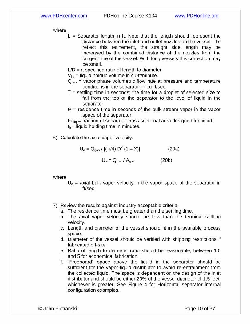
where L = Separator length in ft. Note that the length should represent the
distance between the inlet and outlet nozzles on the vessel. To reflect this refinement, the straight side length may be increased by the combined distance of the nozzles from the tangent line of the vessel. With long vessels this correction may be small.
L/D = a specified ratio of length to diameter. Vliq = liquid holdup volume in cu-ft/minute. Qgas = vapor phase volumetric flow rate at pressure and temperature
conditions in the separator in cu-ft/sec. Τ = settling time in seconds; the time for a droplet of selected size to
fall from the top of the separator to the level of liquid in the separator.
ϴ = residence time in seconds of the bulk stream vapor in the vapor space of the separator.
Faliq = fraction of separator cross sectional area designed for liquid. th = liquid holding time in minutes.
6) Calculate the axial vapor velocity.
Ua = Qgas / [(π/4) D2 (1 – X)] (20a)
Ua = Qgas / Agas (20b)
where Ua = axial bulk vapor velocity in the vapor space of the separator in
ft/sec.
7) Review the results against industry acceptable criteria: a. The residence time must be greater than the settling time. b. The axial vapor velocity should be less than the terminal settling
velocity. c. Length and diameter of the vessel should fit in the available process
space. d. Diameter of the vessel should be verified with shipping restrictions if
fabricated off-site. e. Ratio of length to diameter ratio should be reasonable, between 1.5
and 5 for economical fabrication. f. “Freeboard” space above the liquid in the separator should be
sufficient for the vapor-liquid distributor to avoid re-entrainment from the collected liquid. The space is dependent on the design of the inlet distributor and should be either 20% of the vessel diameter of 1.5 feet, whichever is greater. See Figure 4 for Horizontal separator internal configuration examples.

www.PDHcenter.com PDHonline Course K134 www.PDHonline.org
© John Pietranski Page 11 of 37
8) Optional: Calculate the theoretical droplet sized removed corresponding to the settling velocity calculated in step 1 above using the following equations:
dN = [3 * 0.324 * Ut2 ρgas] / [4 (ρliq – ρgas) g] (21)
dS = [(18 µgas Ut) / [(ρliq – ρgas) g] (22)
dT = [0.5 (dN 0.534 + (dN 1.068 + 4 * dS 1.068) 0.5] 1/0.534 (23)
where dN = drop diameter based on Newton’s Law, in feet. dS = drop diameter based on Stoke’s Law, in feet. µgas = viscosity of vapor in lb/ft-sec.
dT = estimate of droplet diameter that will settle out in separator in feet.
9) If the droplet size is adequate then separator sizing is finished. If the droplet size is too large, choose a smaller coefficient K and repeat steps 1 through 8.
The CCPS procedure was developed for situations in which the droplet size can be as large as 600 microns. In this case, the terminal velocity constant is “anchored” at K = 0.27 ft/sec. In situations where the droplet size is required to be much smaller, lower values of K should be used. The CCPS method does provide several equations to check the theoretical exit droplet size calculated by the assumed K factor used and the fluid physical properties. They have taken the equations for terminal settling velocity and combine Newton’s and Stoke’s Law for drag coefficients to relate fluid properties and terminal velocity to a calculated theoretical droplet diameter. It has been the author’s experience to set up an Excel spreadsheet with the parameters and their relationship equations, determine several simplifying conditions, and then use the trial-and-error techniques to converge on a solution. In particular, reference #14 has a practical approach that covers both sides of the horizontal separator design: selection of a vessel diameter for liquid droplet separation from the gas stream, or, selection of a vessel diameter for liquid holding time considerations. This approach will be used in the horizontal separator industrial example.

www.PDHcenter.com PDHonline Course K134 www.PDHonline.org
© John Pietranski Page 12 of 37
API 521 Sizing Procedures
The API sizing procedure for horizontal separators, referred to as horizontal knock-out drums, like the CCPS technique is limited to single entry and single exit piping configurations. The first step is to determine the drum size required for liquid entrainment separation. Typically, liquid particles separate from the carrier gas stream under two conditions:
1) when the residence time of the vapor or gas stream is equal to or greater than the time required to travel the available vertical height at the dropout velocity of the liquid particles, and
2) when the gas velocity is sufficiently low to permit the liquid droplet
to fall. The vertical height for residence time is usually taken as the distance from the maximum liquid level. For the API technique the separator outlet droplet size range of concerned is in the 300 to 600 micron size. The API application equations are a four (4) step procedure. These steps are listed below:
1) Calculate the dropout velocity, Uc, at the fluid properties using the drag coefficient C from Figure 5.
Ut = 1.15 [(g Dp/ C) ((ρliq/ρgas) -1)] 0.5 (24)
where Ut = settling velocity in ft/sec. C = drag coefficient. C can be obtained from Figure 5 or equation 25. ρliq = liquid phase density in lb/cu-ft.
ρgas = vapor phase density in lb/cu-ft. Dp = droplet diameter that will settle out in separator in feet.
And C, in a similar form to equation 10 is calculated as:
C (NRe) 2 = [0.95E08 Dp
3 ρgas (ρliq-ρgas)] /µgas2] (25)
where
µgas = gas viscosity in centipoise, cP.
2) Consider and calculate liquid retained in the drum. Since API 521 covers
a wide range of process conditions, both in the steady state and dynamic
www.PDHcenter.com PDHonline Course K134 www.PDHonline.org
© John Pietranski Page 13 of 37
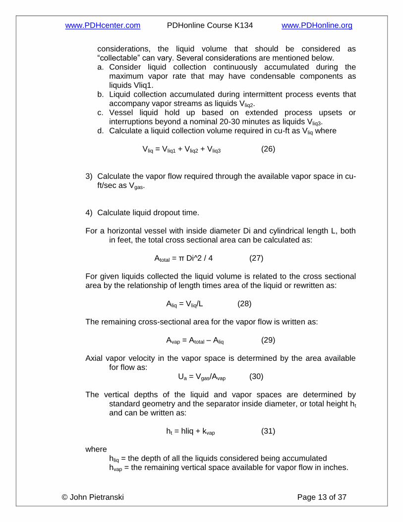
considerations, the liquid volume that should be considered as “collectable” can vary. Several considerations are mentioned below. a. Consider liquid collection continuously accumulated during the
maximum vapor rate that may have condensable components as liquids Vliq1.
b. Liquid collection accumulated during intermittent process events that accompany vapor streams as liquids Vliq2.
c. Vessel liquid hold up based on extended process upsets or interruptions beyond a nominal 20-30 minutes as liquids Vliq3.
d. Calculate a liquid collection volume required in cu-ft as Vliq where
Vliq = Vliq1 + Vliq2 + Vliq3 (26)
3) Calculate the vapor flow required through the available vapor space in cu-ft/sec as Vgas.
4) Calculate liquid dropout time.
For a horizontal vessel with inside diameter Di and cylindrical length L, both in feet, the total cross sectional area can be calculated as:
Atotal = π Di^2 / 4 (27)
For given liquids collected the liquid volume is related to the cross sectional area by the relationship of length times area of the liquid or rewritten as:
Aliq = Vliq/L (28)
The remaining cross-sectional area for the vapor flow is written as:
Avap = Atotal – Aliq (29)
Axial vapor velocity in the vapor space is determined by the area available for flow as:
Ua = Vgas/Avap (30) The vertical depths of the liquid and vapor spaces are determined by
standard geometry and the separator inside diameter, or total height ht and can be written as:
ht = hliq + kvap (31)
where hliq = the depth of all the liquids considered being accumulated
hvap = the remaining vertical space available for vapor flow in inches.

www.PDHcenter.com PDHonline Course K134 www.PDHonline.org
© John Pietranski Page 14 of 37
Given the required vapor flow rate and volume of liquids to be collected, a cylindrical design can be obtained that satisfies these requirements. The minimum separator length is given by:
Lmin = Ua ϴ (32) With the dropout time is determined as:
ϴ = (hvap/12) (1/ Ut) (33) API 521 then refers to utilizing standard separator diameters and facility process space requirements to initiate a series of calculations that assume a separator diameter. The calculation uses specific process needs for the streams along with fluid physical properties to set vessel diameter and lengths. The vessel size and calculations from equations 24 through 33 are compared to the two conditions:
1) when the residence time of the vapor or gas stream is equal to or greater than the time required to travel the available vertical height at the dropout velocity of the liquid particles, and
2) when the gas velocity is sufficiently low to permit the liquid droplet
to fall.
A standard vessel size that meets the above criteria, is suitable for the process layout and design pressure, material of construction, and any corrosion allowance, is then selected as the design.
Vertical Gravity Separators Vertical separation methodology for sizing vessels using the CCPS procedure is similar to the API-521 procedure. There are several differences. Most notably is the minimum attention given to the design in the API-521 procedure. The API design calculations are presented first.
www.PDHcenter.com PDHonline Course K134 www.PDHonline.org
© John Pietranski Page 15 of 37
API 521 Sizing Procedures For vertical vessels, the API calculation procedure selects the maximum vapor velocity as equal to the terminal settling velocity, or otherwise known as the drop out velocity. Using the vapor flow rate and dividing by this velocity gives the cross sectional vessel area.
Acs = Qgas / Ut (34) Consideration for liquid accumulation would determine the height for the liquid phase. The vapor phase volume space is discussed directly for vertical gravity separators in Section 7.3.2.1.1 and concurs with reasonable vapor entry configurations that are common to the horizontal separator design.
CCPS Sizing Procedure Vertical separators are discussed in a five (5) application methodology and are listed below. It assumes that the inlet and outlet vapor piping of the vessel has been evaluated. This is an important consideration since the operation of the vessel is influenced by flashing liquid and pressure swings. It is assumed that this consideration has been accounted for in the piping evaluation. Other information that is required includes the vapor and liquid flow rates and the physical properties used in the calculations. Physical properties that are required include vapor and liquid densities, liquid and vapor viscosities, and liquid surface tension.
1) Calculate the droplet settling velocity from the assumption of an assumed coefficient K and the stream fluid properties.
Ut = K [ (ρliq/ρgas) -1] 0.5 (35)
where Ut = settling velocity in ft/sec. K = terminal velocity constant; 0.27 ft/sec. ρliq = liquid phase density in lb/cu-ft.
ρgas = vapor phase density in lb/cu-ft. In actuality, this is a good starting design decision point. Theoretically, all of the droplets should disengage from the vapor stream at this point. In order to assure the design has the vapor velocity significantly below the settling velocity, we can build in a design factor by adjusting the vapor velocity approach to the dropout velocity

www.PDHcenter.com PDHonline Course K134 www.PDHonline.org
© John Pietranski Page 16 of 37
using a factored approach. Let Vdf = a selected design factor percent from 0 to 100%. The Vapor velocity used for vessel design would then be:
Ut design = Ut * Vdf (36) If we choose 100%, the design velocity reverts back to the theoretical dropout velocity. If we choose 0, we have a “zero” velocity or an infinitely sized vessel. Initially, use an assumption of 50% and review the vessel diameter and height. The design factor can be adjusted as required based on process knowledge. A good rule of thumb is given in reference #14. For separation design that does not include an outlet mist eliminator nor inlet impingement baffle, the design factor can be as low as 15%. This will cause a much larger vessel. Separation design that includes an exit mist eliminator and inlet impingement baffle can use a design factor of 100%. This will minimize vessel size. It should be noted that the process design should dictate mist eliminator and inlet baffle use.
2) Calculate the vessel minimum diameter.
D = [(4/π) Qgas / Ut] 0.5 (37)
where D = Minimum Separator diameter in ft. Qgas = vapor phase volumetric flow rate at pressure and temperature
conditions in the separator in cu-ft/sec.
3) Calculate the vessel height. The total height, tangent-to-tangent, of the separator is the sum of the height required to collect the design volume of liquid, plus the height necessary to disengage liquid from the vapor. If other devices are used, such as flow diverters, mist eliminators, sampling ports, and the like, additional height will be needed. The calculation for height of a vertical separator is outlined as follows:
a. Calculate the volume of liquid collected.
Vliq = Wliq / ρliq (38) where Vliq = total volume of liquid collected in cu-ft. Wliq = mass of liquid collected in lbs. This should reflect the
volume of liquid for all design considerations. ρliq = liquid phase density in lb/cu-ft.
www.PDHcenter.com PDHonline Course K134 www.PDHonline.org
© John Pietranski Page 17 of 37
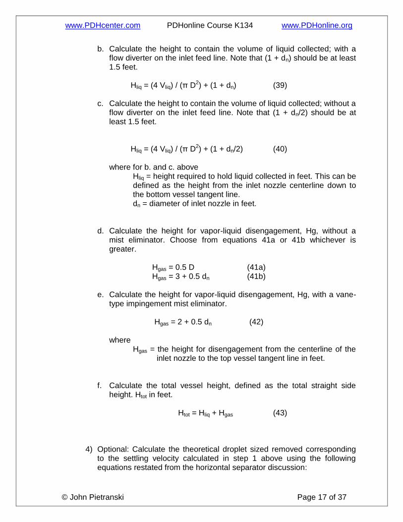
b. Calculate the height to contain the volume of liquid collected; with a flow diverter on the inlet feed line. Note that (1 + dn) should be at least 1.5 feet.
Hliq = (4 Vliq) / (π D2) + (1 + dn) (39)
c. Calculate the height to contain the volume of liquid collected; without a flow diverter on the inlet feed line. Note that (1 + dn/2) should be at least 1.5 feet.
Hliq = (4 Vliq) / (π D2) + (1 + dn/2) (40)
where for b. and c. above
Hliq = height required to hold liquid collected in feet. This can be defined as the height from the inlet nozzle centerline down to the bottom vessel tangent line.
dn = diameter of inlet nozzle in feet.
d. Calculate the height for vapor-liquid disengagement, Hg, without a mist eliminator. Choose from equations 41a or 41b whichever is greater.
Hgas = 0.5 D (41a) Hgas = 3 + 0.5 dn (41b)
e. Calculate the height for vapor-liquid disengagement, Hg, with a vane-
type impingement mist eliminator.
Hgas = 2 + 0.5 dn (42)
where Hgas = the height for disengagement from the centerline of the
inlet nozzle to the top vessel tangent line in feet.
f. Calculate the total vessel height, defined as the total straight side
height. Htot in feet.
Htot = Hliq + Hgas (43)
4) Optional: Calculate the theoretical droplet sized removed corresponding to the settling velocity calculated in step 1 above using the following equations restated from the horizontal separator discussion:

www.PDHcenter.com PDHonline Course K134 www.PDHonline.org
© John Pietranski Page 18 of 37
dN = [3 * 0.324 * Ut2 ρgas] / [4 (ρliq – ρgas) g] (21)
dS = [(18 µgas Ut) / [(ρliq – ρgas) g] (22)
dT = [0.5 ( dN 0.534 + (dN 1.068 + 4 * dS 1.068) 0.5] 1/0.534 (23)
where dN = drop diameter based on Newton’s Law in feet. dS = drop diameter based on Stokes Law in feet. µgas = viscosity of vapor in lb/ft-sec.
dT = estimate of droplet diameter that will settle out in separator in feet.
5) If the droplet size is adequate then separator sizing is finished. If the droplet size is too large, choose a smaller coefficient K and repeat steps 1 through 3.
As stated earlier, the CCPS application equations were developed for situations in which the droplet size can be as large as 600 microns. In this case, the terminal velocity constant is “anchored” at K = 0.27 ft/sec. In situations where the droplet size is required to be much smaller, lower values of K should be used. The CCPS method does provide several equations to check the theoretical exit droplet size calculated by the assumed K factor used and the fluid physical properties. They have taken the equations for terminal settling velocity and combine Newton’s and Stoke’s Law for drag coefficients to relate fluid properties and terminal velocity to a calculated theoretical droplet diameter. Two industrial examples are given in order to demonstrate the calculation techniques for comparing horizontal and vertical separator designs. The two examples calculate the size of each vessel that is needed to remove liquid from a defined inlet vapor stream in order to meet downstream process conditions. It should be noted that separator design dictates the use of standard industrial sizes, and due to the nature of the specific process application, may require trial-and-error solution paths to converge the specific vessel size.

www.PDHcenter.com PDHonline Course K134 www.PDHonline.org
© John Pietranski Page 19 of 37
Table 1 Particle size of droplets in process unit operations.

www.PDHcenter.com PDHonline Course K134 www.PDHonline.org
© John Pietranski Page 20 of 37
Figure 1. Characteristics of liquid particles.

www.PDHcenter.com PDHonline Course K134 www.PDHonline.org
© John Pietranski Page 21 of 37
Figure 2. Industrial Collection Equipment versus Particle Size.
www.PDHcenter.com PDHonline Course K134 www.PDHonline.org
© John Pietranski Page 22 of 37
Figure 3. Fill Fraction as a function of Liquid level in horizontal vessels.

www.PDHcenter.com PDHonline Course K134 www.PDHonline.org
© John Pietranski Page 23 of 37
Figure 4. Horizontal Separator internal configurations.

www.PDHcenter.com PDHonline Course K134 www.PDHonline.org
© John Pietranski Page 24 of 37
Figure 5. API determination of drag coefficient.

www.PDHcenter.com PDHonline Course K134 www.PDHonline.org
© John Pietranski Page 25 of 37
External Force FE
Drag Force
FD
Buoyant Force FB
Figure 6. Forces exerted on a falling body.
Example 1 It is proposed to remove entrained water from a gas stream exhibiting two-phase flow that has very large “rain” droplets of liquids with a horizontal separator similar to the one shown in Figure 4. Downstream equipment can handle a gas stream containing water with droplets that are no larger than 500 microns. Include in the separator design a 1 hour storage capacity for collected liquids. The separator will have an inlet impingement baffle and exit mist eliminator. Use the CCPS
www.PDHcenter.com PDHonline Course K134 www.PDHonline.org
© John Pietranski Page 26 of 37
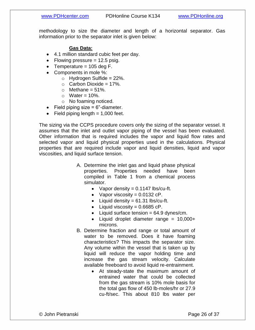
methodology to size the diameter and length of a horizontal separator. Gas information prior to the separator inlet is given below:
Gas Data:
4.1 million standard cubic feet per day.
Flowing pressure = 12.5 psig.
Temperature = 105 deg F.
Components in mole %: o Hydrogen Sulfide = 22%. o Carbon Dioxide = 17%. o Methane = 51%. o Water = 10%. o No foaming noticed.
Field piping size = 6”-diameter.
Field piping length = 1,000 feet.
The sizing via the CCPS procedure covers only the sizing of the separator vessel. It assumes that the inlet and outlet vapor piping of the vessel has been evaluated. Other information that is required includes the vapor and liquid flow rates and selected vapor and liquid physical properties used in the calculations. Physical properties that are required include vapor and liquid densities, liquid and vapor viscosities, and liquid surface tension.
A. Determine the inlet gas and liquid phase physical properties. Properties needed have been compiled in Table 1 from a chemical process simulator.
Vapor density = 0.1147 lbs/cu-ft.
Vapor viscosity = 0.0132 cP.
Liquid density = 61.31 lbs/cu-ft.
Liquid viscosity = 0.6685 cP.
Liquid surface tension = 64.9 dynes/cm.
Liquid droplet diameter range = 10,000+ microns.
B. Determine fraction and range or total amount of water to be removed. Does it have foaming characteristics? This impacts the separator size. Any volume within the vessel that is taken up by liquid will reduce the vapor holding time and increase the gas stream velocity. Calculate available freeboard to avoid liquid re-entrainment.
At steady-state the maximum amount of entrained water that could be collected from the gas stream is 10% mole basis for the total gas flow of 450 lb-moles/hr or 27.9 cu-ft/sec. This about 810 lbs water per

www.PDHcenter.com PDHonline Course K134 www.PDHonline.org
© John Pietranski Page 27 of 37
hour. For a 1-hour storage capacity this calculates to about 97 gals, 13.2 cu-ft or a flow rate of 0.22 cu-ft/min.
Vliq = 0.22 cu-ft/min liquid holdup volume.
Qgas = =27.9 cu-ft/sec vapor phase volumetric flow rate at pressure and temperature conditions in the separator.
No foaming characteristics as given in problem statement.
C. Determine pipeline actual velocity:
Molar flow = 450 lb moles/hr.
Volumetric Flow = 1,672 acfm.
For 6”-dia pipe, Velocity = 139 fps.
The axial vapor velocity to prevent entrainment from the separator liquid level surface will dictate inlet and outlet vessel nozzle sizes and should be compared to the supply line velocity.
D. Determine the smallest droplet size to be
removed at the separator outlet. The separator removal efficiency is dependent on the selection of droplet size being removed. Calculate residence time and settling rate.
Given in problem statement, the largest droplet size desired is about 500 microns.
Inlet droplet size is estimated at 10,000 microns.
The CCPS calculations are a nine (9) step procedure. These steps are listed below: 10) Calculate the settling velocity from the assumption of coefficient K and the
fluid properties. Using equation 11 from the course and the Table 1 values:
Ut = K [(ρliq/ρgas) -1] 0.5 (11)
where Ut = terminal settling or drop out velocity in ft/sec. K = terminal velocity constant; 0.27 ft/sec. ρliq = liquid phase density in lb/cu-ft. ρgas = vapor phase density in lb/cu-ft.
Ut = 6.24 ft/sec
www.PDHcenter.com PDHonline Course K134 www.PDHonline.org
© John Pietranski Page 28 of 37
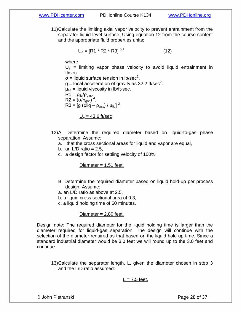
11) Calculate the limiting axial vapor velocity to prevent entrainment from the separator liquid level surface. Using equation 12 from the course content and the appropriate fluid properties units:
Ue = [R1 * R2 * R3] 0.1 (12)
where Ue = limiting vapor phase velocity to avoid liquid entrainment in ft/sec. σ = liquid surface tension in lb/sec2.
g = local acceleration of gravity as 32.2 ft/sec2. µliq = liquid viscosity in lb/ft-sec. R1 = ρliq/ρgas.
R2 = (σ/ρgas) 4.
R3 = [g (ρliq – ρgas) / µliq] 2
Ue = 43.6 ft/sec
12) A. Determine the required diameter based on liquid-to-gas phase separation. Assume: a. that the cross sectional areas for liquid and vapor are equal, b. an L/D ratio = 2.5, c. a design factor for settling velocity of 100%.
Diameter = 1.51 feet.
B. Determine the required diameter based on liquid hold-up per process design. Assume:
a. an L/D ratio as above at 2.5, b. a liquid cross sectional area of 0.3, c. a liquid holding time of 60 minutes.
Diameter = 2.80 feet.
Design note: The required diameter for the liquid holding time is larger than the diameter required for liquid-gas separation. The design will continue with the selection of the diameter required as that based on the liquid hold up time. Since a standard industrial diameter would be 3.0 feet we will round up to the 3.0 feet and continue.
13) Calculate the separator length, L, given the diameter chosen in step 3 and the L/D ratio assumed:
L = 7.5 feet.

www.PDHcenter.com PDHonline Course K134 www.PDHonline.org
© John Pietranski Page 29 of 37
14) Calculate the fill fraction, X, or ratio of cross sectional area occupied by
the liquid as a ratio of the total vessel cross sectional area using the calculated D, L, and liquid hold up required. This is the same X as the y-axis in Figure 3 or equation 14. Use equation 14b.
X= 0.249
Then either use Figure 3 or a trial-and-error iteration of equation 14a by
assuming y until the correct X is calculated. The liquid level fraction y, which is also hf/D, and with the D and L calculated above, calculate both the height of liquid fill and the fraction area and volume. Using the liquid fill height, calculate the vapor space “freeboard”. The area for vapor flow can be obtained by subtracting out the liquid fill area and the axial vapor velocity can be calculated.
From Figure 3 y = 0.3 or
From equation 14a trial-and-error iteration y = 0.297
hf = 0.89 feet of liquid fill Fraction area of liquid fill = 0.25
Area liquid fill = 1.76 sq-ft.
Freeboard height = 2.1 feet. Vapor flow area = 5.31 sq-ft.
where L = Separator length in ft. Note that the length should represent the
distance between the inlet and outlet nozzles on the vessel. To reflect this refinement, the straight side length may be increased by the combined distance of the nozzles from the tangent line of the vessel. With long vessels this correction may be small.
Vliq = liquid holdup volume in cu-ft. Qgas = vapor phase volumetric flow rate at pressure and temperature
conditions in the separator in cu-ft/sec.
15) Calculate the axial vapor velocity from equation 20b. Calculate the
settling and residence times from equations 17 and 19:
Τ = D (1-y)/Ut (17)
ϴ = L/Ua (19)

www.PDHcenter.com PDHonline Course K134 www.PDHonline.org
© John Pietranski Page 30 of 37
Ua = Qgas / Agas (20b) where
Ua = axial bulk vapor velocity in the vapor space of the separator in ft/sec.
Agas = cross sectional area for vapor flow in the separator in sq-ft.
Ua = 5.25 ft/sec
16) Review the results against industry acceptable criteria: a. The residence time must be greater than the settling time. b. The axial vapor velocity should be less than the entrainment limiting
velocity. c. Length and diameter of the vessel should fit in the available process
space. d. Diameter of the vessel should be verified with shipping restrictions if
fabricated off-site. e. Ratio of length to diameter ratio should be reasonable, between 1.5
and 5 for economical fabrication. f. “Freeboard” space above the liquid in the separator should be
sufficient for the vapor-liquid distributor to avoid re-entrainment from the collected liquid. The space is dependent on the design of the inlet distributor and should be either 20% of the vessel diameter of 1.5 feet, whichever is greater. See Figure 4. For Horizontal separator internal configuration examples.
Step 7 Check
Is residence time > settling time?
Residence time available is 1.4
seconds; that is greater than
required settling time of 0.34
seconds
Is axial vapor velocity <
settling/drop out velocity?
Yes; axial velocity is 5.2 ft/sec;
settling velocity is 6.2 ft/sec.
Is Length and Diameter
reasonable? Diameter = 3.5’ Length = 7.5’
Is Diameter OK for shipping; i.e. <
12-16 ft? 3’
Is L/D between 1.5 and 5.0? 2.5
Is freeboard reasonable; 1.5 ft or 20% of Diameter whichever is
greater?
Yes Freeboard = 2.1’

www.PDHcenter.com PDHonline Course K134 www.PDHonline.org
© John Pietranski Page 31 of 37
17) Optional: Calculate the theoretical droplet sized removed corresponding to the settling velocity calculated in step 1 above using equations 17, 18, and 19.
dN = [3 * 0.324 * Ut2 ρgas] / [4 (ρliq – ρgas) g] (17)
dS = [(18 µgas Ut) / [(ρliq – ρgas) g] (18)
dT = [0.5 (dN 0.534 + (dN 1.068 + 4 * dS 1.068) 0.5] 1/0.534 (19)
where dN = drop diameter based on Newton’s Law, in feet. dS = drop diameter based on Stoke’s Law, in feet. µgas = viscosity of vapor in lb/ft-sec.
dT = estimate of droplet diameter that will settle out in separator in feet.
Step 8 Check Droplet size out of Separator
for assumptions of K and rest
Dn in feet = 0.00055
Dn in microns = 167.7
Ds in feet = 0.00071
Ds in microns = 215.1
Dt in feet = 0.00156
Dt in microns = 476.6
Dt in microns = 477.
18) If the droplet size is OK then separator sizing is finished. If the droplet size is too large, choose a smaller coefficient K and repeat steps 1 through 8.
Dt in microns = 477, which is acceptable for the example 1 requirements.
Table 1. Physical Properties of Example 1.
Two-Phase Entering Separator
Density, lbs/cu-ft 0.1147
Vapor Viscosity, cP 0.0132

www.PDHcenter.com PDHonline Course K134 www.PDHonline.org
© John Pietranski Page 32 of 37
Liquid droplet diameter, microns 10,000
Liquid Viscosity, cP 0.6685
Temperature, deg F 105
Pressure, psig 12.5
Vapor Phase Leaving Separator
Density, lbs/cu-ft 0.1147
Viscosity, cP 0.013
Liquid droplet diameter, microns 200
Liquid Phase Leaving Separator
Density, lbs/cu-ft 61.31
Viscosity, cP 0.6685
Surface Tension, dynes/cm 64.8595
www.PDHcenter.com PDHonline Course K134 www.PDHonline.org
© John Pietranski Page 33 of 37
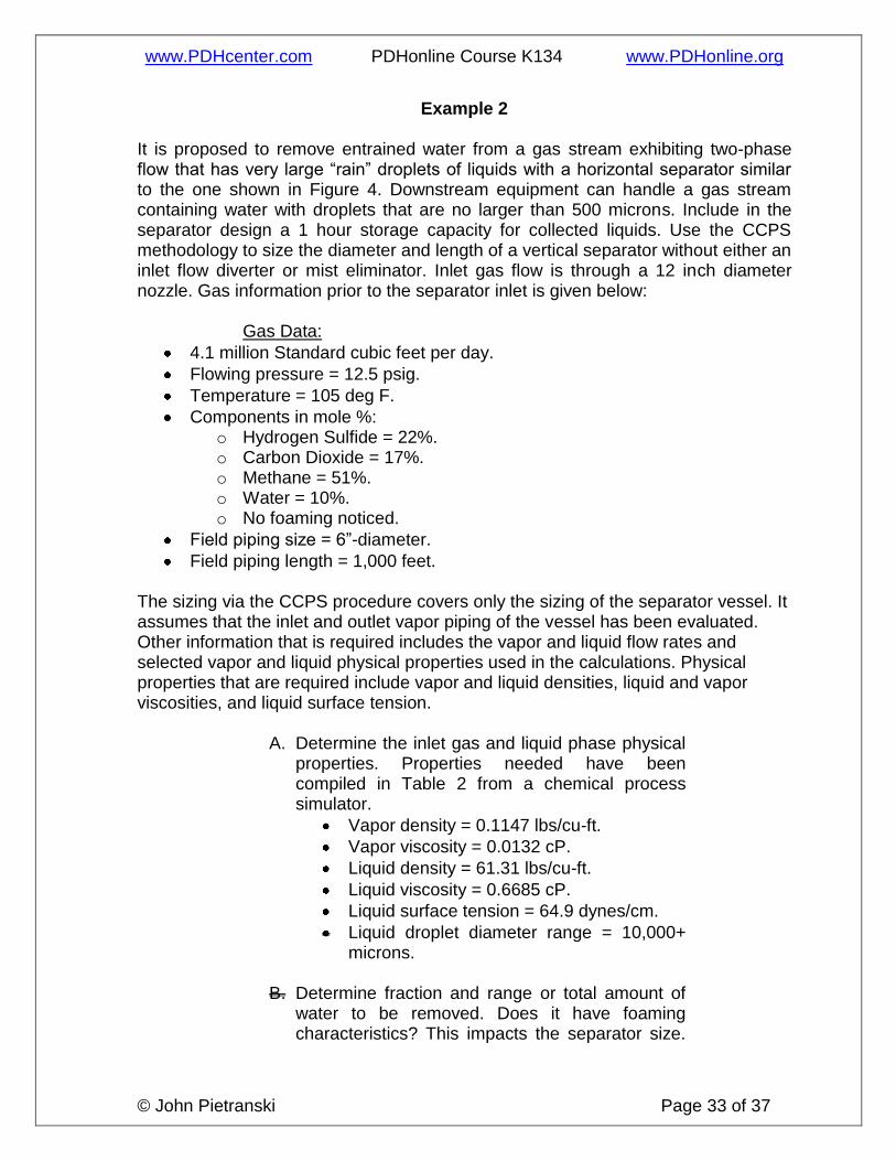
Example 2 It is proposed to remove entrained water from a gas stream exhibiting two-phase flow that has very large “rain” droplets of liquids with a horizontal separator similar to the one shown in Figure 4. Downstream equipment can handle a gas stream containing water with droplets that are no larger than 500 microns. Include in the separator design a 1 hour storage capacity for collected liquids. Use the CCPS methodology to size the diameter and length of a vertical separator without either an inlet flow diverter or mist eliminator. Inlet gas flow is through a 12 inch diameter nozzle. Gas information prior to the separator inlet is given below:
Gas Data:
4.1 million Standard cubic feet per day.
Flowing pressure = 12.5 psig.
Temperature = 105 deg F.
Components in mole %: o Hydrogen Sulfide = 22%. o Carbon Dioxide = 17%. o Methane = 51%. o Water = 10%. o No foaming noticed.
Field piping size = 6”-diameter.
Field piping length = 1,000 feet.
The sizing via the CCPS procedure covers only the sizing of the separator vessel. It assumes that the inlet and outlet vapor piping of the vessel has been evaluated. Other information that is required includes the vapor and liquid flow rates and selected vapor and liquid physical properties used in the calculations. Physical properties that are required include vapor and liquid densities, liquid and vapor viscosities, and liquid surface tension.
A. Determine the inlet gas and liquid phase physical properties. Properties needed have been compiled in Table 2 from a chemical process simulator.
Vapor density = 0.1147 lbs/cu-ft.
Vapor viscosity = 0.0132 cP.
Liquid density = 61.31 lbs/cu-ft.
Liquid viscosity = 0.6685 cP.
Liquid surface tension = 64.9 dynes/cm.
Liquid droplet diameter range = 10,000+ microns.
B. Determine fraction and range or total amount of
water to be removed. Does it have foaming characteristics? This impacts the separator size.

www.PDHcenter.com PDHonline Course K134 www.PDHonline.org
© John Pietranski Page 34 of 37
Any volume within the vessel that is taken up by liquid will reduce the vapor holding time and increase the gas stream velocity.
At steady-state the maximum amount of entrained water that could be collected from the gas stream is 10% mole basis for the total gas flow of 450 lb-moles/hr or 27.9 cu-ft/sec. This about 810 lbs water per hour. For a 1-hour storage capacity this calculates to about 97 gals or 13.2 cu-ft.
Vliq = 0.22 cu-ft/min liquid holdup volume.
Qgas = =27.9 cu-ft/sec vapor phase volumetric flow rate at pressure and temperature conditions in the separator.
No foaming characteristics as given in problem statement.
C. Determine the smallest droplet size to be
removed at the separator outlet. The separator removal efficiency is dependent on the selection of droplet size being removed. Calculate residence time and settling rate.
Given in problem statement, the largest droplet size desired is about 500 microns.
Inlet droplet size is estimated at 10,000 microns.
Vertical separators are discussed in a five (5) step calculation methodology and are listed below.
19) Calculate the settling velocity from the assumption of coefficient K and the fluid properties. Using equation 11 from the course and the Table 1 values:
Ut = K [(ρliq/ρgas) -1] 0.5 (11)
where Ut = terminal settling or drop out velocity in ft/sec. K = terminal velocity constant; 0.27 ft/sec. ρliq = liquid phase density in lb/cu-ft. ρgas = vapor phase density in lb/cu-ft.
Ut = 6.24 ft/sec
www.PDHcenter.com PDHonline Course K134 www.PDHonline.org
© John Pietranski Page 35 of 37
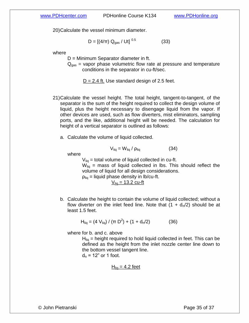
20) Calculate the vessel minimum diameter.
D = [(4/π) Qgas / Ut] 0.5 (33)
where D = Minimum Separator diameter in ft. Qgas = vapor phase volumetric flow rate at pressure and temperature
conditions in the separator in cu-ft/sec.
D = 2.4 ft. Use standard design of 2.5 feet.
21) Calculate the vessel height. The total height, tangent-to-tangent, of the
separator is the sum of the height required to collect the design volume of liquid, plus the height necessary to disengage liquid from the vapor. If other devices are used, such as flow diverters, mist eliminators, sampling ports, and the like, additional height will be needed. The calculation for height of a vertical separator is outlined as follows:
a. Calculate the volume of liquid collected.
Vliq = Wliq / ρliq (34)
where Vliq = total volume of liquid collected in cu-ft. Wliq = mass of liquid collected in lbs. This should reflect the
volume of liquid for all design considerations. ρliq = liquid phase density in lb/cu-ft.
Vliq = 13.2 cu-ft
b. Calculate the height to contain the volume of liquid collected; without a
flow diverter on the inlet feed line. Note that (1 + dn/2) should be at least 1.5 feet.
Hliq = (4 Vliq) / (π D2) + (1 + dn/2) (36)
where for b. and c. above
Hliq = height required to hold liquid collected in feet. This can be defined as the height from the inlet nozzle center line down to the bottom vessel tangent line.
dn = 12” or 1 foot.
Hliq = 4.2 feet

www.PDHcenter.com PDHonline Course K134 www.PDHonline.org
© John Pietranski Page 36 of 37
c. Calculate the height for vapor-liquid disengagement, Hgas, without a mist eliminator. Choose from equations 36a or 36b whichever is greater.
Hgas = 0.5 D (37a) Hgas = 3 + 0.5 dn (37b)
where Hgas = the height for disengagement from the centerline of the
inlet nozzle to the top vessel tangent line in feet.
Hgas = 3.5 d. Calculate the total vessel height, defined as the total straight side
height. Htot in feet.
Htot = Hliq + Hgas (39) Htot = 7.7 feet. Use 8 feet as design length.
22) Optional: Calculate the theoretical droplet sized removed corresponding to the settling velocity calculated in step 1 above using the following equations restated from the horizontal separator discussion:
dN = [3 * 0.324 * Ut2 ρgas] / [4 (ρliq – ρgas) g] (17)
dS = [(18 µgas Ut) / [(ρliq – ρgas) g] (18)
dT = [0.5 (dN 0.534 + (dN 1.068 + 4 * dS 1.068) 0.5] 1/0.534 (19)
where dN = drop diameter based on Newton’s Law in feet. dS = drop diameter based on Stokes Law in feet. µgas = viscosity of vapor in lb/ft-sec.
dT = estimate of droplet diameter that will settle out in separator in feet.
23) If the droplet size is adequate then separator sizing is finished. If the droplet size is too large, choose a smaller coefficient K and repeat steps 1 through 3.

www.PDHcenter.com PDHonline Course K134 www.PDHonline.org
© John Pietranski Page 37 of 37
Step 8 Check Droplet size out of Separator
for assumptions of K and rest
Dn in feet = 0.00055
Dn in microns = 167.7
Ds in feet = 0.00071
Ds in microns = 215.1
Dt in feet = 0.00156
Dt in microns = 476.6
Dt in microns = 477.
Dt in microns = 477, which is acceptable for the example 2 requirements.
Table 2. Physical Properties of Example 2.
Two-Phase Entering Separator
Density, lbs/cu-ft 0.1147
Vapor Viscosity, cP 0.0132
Liquid droplet diameter, microns 10,000
Liquid Viscosity, cP 0.6685
Temperature, deg F 105
Pressure, psig 12.5
Vapor Phase Leaving Separator
Density, lbs/cu-ft 0.1147
Viscosity, cP 0.013
Liquid droplet diameter, microns 200
Liquid Phase Leaving Separator
Density, lbs/cu-ft 61.31
Viscosity, cP 0.6685
Surface Tension, dynes/cm 64.8595