SENTRON 3NP1 Fuse Switch Disconnectors - Siemens€¦ · SENTRON 3NP1 Fuse Switch Disconnectors ......
4
SENTRON 3NP1 Fuse Switch Disconnectors Switching, Protection, Measuring and Monitoring Devices Our 3NP1 series offers you safe protection in the event of overload and short circuit. The SENTRON 3NP1 fuse switch disconnector facilitates assembly for floor mounting, on standard mounting rails and busbar systems. 7 Easy and safe maintenance The 3NP1 series is well equipped for high requirements. With its large inspection windows, type and condition (indicators) of the fuses used can be ideally identified. The clearly visible isolating distance per- mits easy and safe maintenance. 7 Highest plant availability The fuse switch disconnector can also be fitted with an electromechanical or elec- tronic fuse monitoring and innovative line monitoring function. All this makes the SENTRON 3NP1 fuse switch disconnector the load breaker switch for maximum plant availability. Highlights 7 Flexible and quick assembly for floor mounting on standard mounting rails and busbar systems 7 Easy and safe maintenance through large inspection windows 7 Maximum plant availability thanks to the electromechanical/electronic fuse monitoring and innovative line moni- toring function Answers for infrastructure. © Siemens AG 2010
Transcript of SENTRON 3NP1 Fuse Switch Disconnectors - Siemens€¦ · SENTRON 3NP1 Fuse Switch Disconnectors ......

SENTRON 3NP1Fuse Switch Disconnectors
Switching, Protection, Measuring and Monitoring Devices
Our 3NP1 series offers you safe protection in the event of overload and short circuit. The SENTRON 3NP1 fuse switch disconnector facilitates assembly for floor mounting, on standard mounting rails and busbar systems.
7 Easy and safe maintenanceThe 3NP1 series is well equipped for high requirements. With its large inspection windows, type and condition (indicators) of the fuses used can be ideally identified. The clearly visible isolating distance per-mits easy and safe maintenance.
7 Highest plant availabilityThe fuse switch disconnector can also be fitted with an electromechanical or elec-tronic fuse monitoring and innovative line monitoring function. All this makes the SENTRON 3NP1 fuse switch disconnector the load breaker switch for maximum plant availability.
Highlights
7 Flexible and quick assembly for floor mounting on standard mounting rails and busbar systems
7 Easy and safe maintenance through large inspection windows
7 Maximum plant availability thanks to the electromechanical/electronic fuse monitoring and innovative line moni-toring function
Answers for infrastructure.
© Siemens AG 2010

Switch disconnectors2
Switch disconnectors3NP1 fuse switch disconnectors up to 630 A
Overview of components and accessory parts
Modular design of the switch disconnector with universally standardized accessories
SENTRON 3NP1 fuse switch disconnector
Cover support
Reach-around protection for Siemens busbar system
Reach-around protection for Rittal busbar system
Locking device
Auxiliary switch with actuator
Molded-plastic masking frame
Fuse carrier with MFM electromechanical fuse monitoring
Fuse carrier with EFM 20/25 electronic fuse monitoring
Fuse carrier with EFM 10 electronic fuse monitoring
Box terminal
Auxiliary conductor connection for box terminal
Flat connector
Auxiliary conductor connection for flat connector
Deep-drawn connection module
Prism terminal
Auxiliary conductor connection for prism terminal
Saddle terminal
Cable connection cover with rear reach-around protection
Cable connection cover
NS
G0_
0023
5
© Siemens AG 2010
Switch disconnectors 3
Overview
Benefits when it comes to planning• High packing density possible in switchgears• Cable feeder (top/bottom) without intervention in the internal
conducting paths can be converted at any time• Only one device variant for applications in industry and infra-
structure thanks to touch and reach-around protection as a standard feature
• Also suitable for the Rittal RiLine60 busbar systems• Busbar contact can be converted at any time from
5 mm to 10 mm• Uniform grid sizes for easiest configuration
Benefits
Benefits in the control cabinet• Quick assembly as a result of snap-on for BG000/BG00• Solid fixing for the large and heavy device versions
(BG1, BG2, BG3) through screw fixing• Cheap solution for occasional switching and for securing
space-saving feeders• Load tables for use at higher temperatures or with semi-
conductor fuses are available• Cable or laminated conductors can be connected using flat
terminals, saddle terminals, prism terminals or box terminals• Shielding capability of busbar supports
Added value in operation• Lockable and closeable against unauthorized operation• Expanded touch protection – hand-safe with removed
handle units• Fuse monitoring permits remote signaling, simplifies error
detection locally and can prevent cost-intensive plant shutdowns (incl. network monitoring function for EFM20)
• A high degree of safety is guaranteed during maintenance work in the switchgear by the standard grip and touch protection
Field of application
• Cable feeders• Switching/fusing of compensation modules• Fusing (with SITOR) of frequency converter and soft starter• Cable distributor• Switchgear and switch cabinets• Machinery and plant• Compensation modules and switch cabinets
International standards and approvals• IEC 60947-1 / EN 60947-1 • IEC 60947-3 / EN 60947-3 • Isolating features according to IEC 60947-2 / EN 60947-2
(VDE 0660-107)
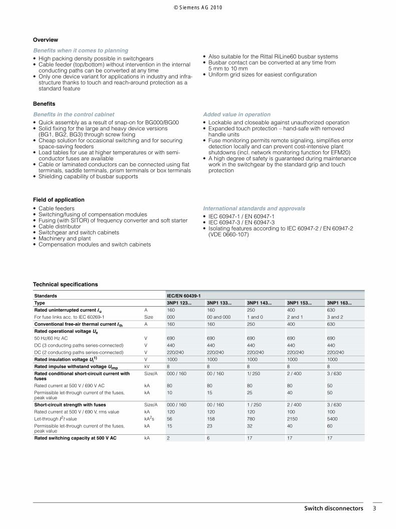
Technical specifications
Standards IEC/EN 60439-1
Type 3NP1 123... 3NP1 133... 3NP1 143... 3NP1 153... 3NP1 163...
Rated uninterrupted current Iu A 160 160 250 400 630
For fuse links acc. to IEC 60269-1 Size 000 00 and 000 1 and 0 2 and 1 3 and 2
Conventional free-air thermal current Ith A 160 160 250 400 630
Rated operational voltage Ue
50 Hz/60 Hz AC V 690 690 690 690 690
DC (3 conducting paths series-connected) V 440 440 440 440 440
DC (2 conducting paths series-connected) V 220/240 220/240 220/240 220/240 220/240
Rated insulation voltage Ui1) V 1000 1000 1000 1000 1000
Rated impulse withstand voltage Uimp kV 8 8 8 8 8
Rated conditional short-circuit current with fuses
Size/A 000 / 160 00 / 160 1/ 250 2 / 400 3 / 630
Rated current at 500 V / 690 V AC kA 80 80 80 80 50
Permissible let-through current of the fuses, peak value
kA 10 15 25 40 50
Short-circuit strength with fuses Size/A 000 / 160 00 / 160 1 / 250 2 / 400 3 / 630
Rated current at 500 V / 690 V, rms value kA 120 120 120 100 100
Let-through I2t value kA2s 56 158 780 2150 5400
Permissible let-through current of the fuses, peak value
kA 15 23 32 40 60
Rated switching capacity at 500 V AC kA 2 6 17 17 17
© Siemens AG 2010
Siemens AGIndustry SectorBuilding Technologies DivisionPostfach 10 09 5393009 REGENSBURGGERMANY
www.siemens.com/lowvoltage
The information provided in this brochure contains descriptions or characteristics of perfor-mance which in case of actual use do not always apply as described or which may change asa result of further development of the products. An obligation to provide the respective char-acteristics shall only exist if expressly agreed in the terms of contract. Availability and techni-cal specifications are subject to change without notice.All product designations may be registered trademarks or product names of Siemens AG orsupplier companies whose use by third parties for their own purposes may violate the rightsof the owner.
© Siemens AG 2010 • Order No.: E10003-E38-10T-G2321-7600 • PI 0910 1. DB En
1) Up to pollution degree 2, above this Ui = 690 V.2) Only with isolating links; otherwise, please observe specifications of fuse
manufacturer.
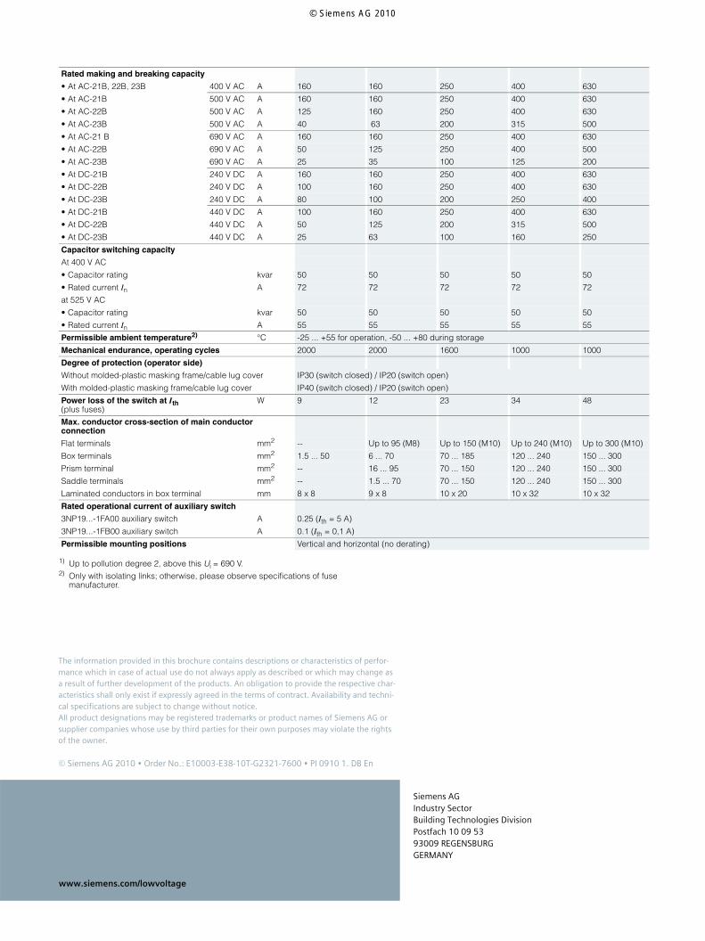
Rated making and breaking capacity
• At AC-21B, 22B, 23B 400 V AC A 160 160 250 400 630
• At AC-21B 500 V AC A 160 160 250 400 630
• At AC-22B 500 V AC A 125 160 250 400 630
• At AC-23B 500 V AC A 40 63 200 315 500
• At AC-21 B 690 V AC A 160 160 250 400 630
• At AC-22B 690 V AC A 50 125 250 400 500
• At AC-23B 690 V AC A 25 35 100 125 200
• At DC-21B 240 V DC A 160 160 250 400 630
• At DC-22B 240 V DC A 100 160 250 400 630
• At DC-23B 240 V DC A 80 100 200 250 400
• At DC-21B 440 V DC A 100 160 250 400 630
• At DC-22B 440 V DC A 50 125 200 315 500
• At DC-23B 440 V DC A 25 63 100 160 250
Capacitor switching capacity
At 400 V AC
• Capacitor rating kvar 50 50 50 50 50
• Rated current In A 72 72 72 72 72
at 525 V AC
• Capacitor rating kvar 50 50 50 50 50
• Rated current In A 55 55 55 55 55
Permissible ambient temperature2) °C -25 ... +55 for operation, -50 ... +80 during storage
Mechanical endurance, operating cycles 2000 2000 1600 1000 1000
Degree of protection (operator side)
Without molded-plastic masking frame/cable lug cover IP30 (switch closed) / IP20 (switch open)
With molded-plastic masking frame/cable lug cover IP40 (switch closed) / IP20 (switch open)
Power loss of the switch at Ith (plus fuses)
W 9 12 23 34 48
Max. conductor cross-section of main conductor connection
Flat terminals mm2 -- Up to 95 (M8) Up to 150 (M10) Up to 240 (M10) Up to 300 (M10)
Box terminals mm2 1.5 ... 50 6 ... 70 70 ... 185 120 ... 240 150 ... 300
Prism terminal mm2 -- 16 ... 95 70 ... 150 120 ... 240 150 ... 300
Saddle terminals mm2 -- 1.5 ... 70 70 ... 150 120 ... 240 150 ... 300
Laminated conductors in box terminal mm 8 x 8 9 x 8 10 x 20 10 x 32 10 x 32
Rated operational current of auxiliary switch
3NP19...-1FA00 auxiliary switch A 0.25 (Ith = 5 A)
3NP19...-1FB00 auxiliary switch A 0.1 (Ith = 0,1 A)
Permissible mounting positions Vertical and horizontal (no derating)
© Siemens AG 2010