Sensors Actuator Command Signal Sensing signal Microprocessor or Microcontroller PLANT (Robot,...
37
Sensors Actuator Command Signal Sensing signal Microprocessor or Microcontroller PLANT (Robot, Autonomous Guided vehicle, Numerical Controlled Machine, Vehicle engines, Consumer products, Conveyor systems, Assembly systems, Cranes, Defense equipments, Air craft engines, Other machines, consumer products, etc) Control code Parameter, variables Actua tion Mechanical components Physically, a mechatronic system is composed of four prime components. They are sensors, actuators, controllers and mechanical components. Figure shows a schematic diagram of a mechatronic system integrated with all the above components.
-
Upload
carmel-hubbard -
Category
Documents
-
view
240 -
download
1
Transcript of Sensors Actuator Command Signal Sensing signal Microprocessor or Microcontroller PLANT (Robot,...

Sensors
Actuator
Command SignalSensing signal
Microprocessoror
Microcontroller
PLANT
(Robot, Autonomous Guided vehicle, Numerical Controlled Machine, Vehicle engines, Consumer products, Conveyor systems, Assembly systems,
Cranes, Defense equipments, Air craft engines, Other machines, consumer products, etc)
Control code
Parameter, variables Actuation
Mechanical components
Physically, a mechatronic system is composed of four prime components. They are sensors, actuators, controllers and mechanical components. Figure shows a schematic diagram of a mechatronic system integrated with all the above components.

N
S
NS
Stator
(a)
Magnetic poles
Rotor
ples of operation. They use permanent magnets, electromagn-ets, and exploit the electromagnetic phenomenon in order to produce the actuation. Electromechanical actuators are DC, AC and stepper motors. DC Motor is the most versatile actuator and sometimes called rotating machine. The DC motor has two parts, stator and rotor. The stator is the outer part of the motor which contains evenly spaced magnetic poles as shown.
Actuators are broadly categorized into three groups, namely, Electromechanical actuators, Fluid power actuators and Active material based actuators. Electro-mechanical actuators are used to efficiently convert electrical energy into mechanical energy. Magnetism is basis of their princi-

aR
+
-
aI
inVbemfE
Magnetic field
(a)
(b)
fR
aR
+
-
aI
inVbemfE
Shunt coil/winding
fI
inI
fR
Series coil/winding
aRaI
+
-
inVbemfE
(c)
Practically two windings are there within the electromag-netic type motor system, namely, stator winding (s) and rotor winding (s). The stator winding (s) is called field coil or field winding.
(a) Separately excited electromagnetic DC motor(b) Self-excited wound-field shunt configuration(c) Self-excited wound-field series configuration

Energy transducer(Generator)
Mechanical Energy/Power Electrical Energy/Power
Energy transducer(Motor)
Electrical Energy/Power Mechanical Energy/Power
Self-excited field energy
A DC motor converts the electrical energy to mechanical energy. The torque is produced due to input current. In reverse situation, the torque, which is equivalent to mechanical energy, can produce current that is equivalent to electrical energy. This reverse process is utilized for the design of DC generator. Figure-7.4 illustrates schematic diagram of typical DC motor and DC generator.

Brushed DC Motor (a) The rotor electr-
omagnet at an instant;
(b) The rotor electr-omagnet before the rotor current flips.
(c) The rotor electr-omagnet after the rotor current flips
(d) A simple brush-ed DC motor illustration
(e) Commutator-brush arrangement

Pole-1
Pole-2
Phase-1
Phase-3
Phase-2Phase-4
Stator
Rotor
(a)
Many applications require precise positioning control. The alternative is the stepper motor. The stepper motor also consists of a rotor and stator. As the name suggests, the stepper motor steps a bit at a time. The motor can be controlled using a microcontroller as it can responds to digital pulse trains. The rotor of the motor rotates a specified number of degrees by each pulse the motor receives from its controller. The motion caused by one pulse is called one step.

S
N
S N
N
S
S N
N
S
N S
S
N
N S
(a) (b)
(c) (d)
N S
S N
N
S
S
N
N-S Axis of the stator N-S Axis
of the stator
N-S Axis of the stator
N-S Axis of the stator
There are only four possible positions of the rotor when all the phases are excited. In this typical case, the step size is 90o.

N
S
N S N S
S
N
S N S N
S
N
N S
S
S
N
S
S N
N
S
N S
S N S
N
S N
N S N
S S
N
N
S
(a) (b) (c) (d)
(e) (f) (g) (h)
In order to have better precision, the number of step size can be increased by building more number of poles, phases and introducing proper control connections within the stator circuits. A control scheme with 45 degree step size.

Cylinder
Rod
Air valve (air controller)
Chamber-1 Chamber-2
LOAD
To pressurized air
Spring
Piston Movement
Pneumatic actuators cause something to move by taking the advantage of potential energy. The actuators in their conventional form are basically called pneumo-mechanical devices and are used to automate industrial tasks of simple but iterative nature. The actuator has three components; cylinder, piston and valve. The cylinder is a hollow chamber into which the external compressed air is allowed to enter so as to enable the piston to move. The linear actuators convert the potential energy in the compressed air into mechanical energy in terms of linear motion. Linear actuators are of four types. Figure shows single-rod single acting type.

Piston
Cylinder
Rod
Air valve-1 (air controller) Air valve-2
Chamber-1 Chamber-2
LOAD
Movement
Pressurized air Pressurized air
Linear single-rod double acting
The single-rod double acting actuators have one rod (piston) two ports (Figure-7.10). Compressed air is sent to one side of the chamber and the air in the other side is allowed to escape. The piston is thus pushed to one end of the cylinder. When compressed air is allowed to enter in to the other side and the first side is allowed to exhaust, then the piston is pushed back.

Air valve-2Air valve-1 (air controller)
LOAD LOAD
Chamber-1 Chamber-2Movement Movement
Linear double-rod double acting type actuator has two rods and two ports as illustrated in the Figure

Load Carriage
To air supply To air supply
(c)
Movement
(b)
Chamber-1 Chamber-2
(a)
The rodless type actuator does not have a rod. The basic operation of rodless actuators is similar to the standard cylinders. However, instead of an extending rod, a rodless carriage is supported by bearings within the main cylinder. This gives the rodless actuator the ability to guide and support a load.

controller
Solenoid Spring endCurrent signal
LOAD
VALVE
Chamber-1 Chamber-2
Chamber Chamber
Inlet air pressureCore movement
Spool
Valve is a device for closing or modifying the passage through a pipe, outlet, inlet in order to stop, allow, or control the flow of a fluid or air. In case of pneumatic actuators valves act as the controlling element to control the flow of air into the chamber of the cylinder.

SHAFT
INLET
OUTLET
Pinion
Rack
Rack
SHAFT SHAFT
OUTLET
INLET
(a)
(b)
Some of the hydraulic actuator are designed to provide rotary movement.
These types of actuators provide torque. There are many types as far as design is concerned, but importantly rack and pinion type and gear-motor type actuators are employed in industrial applications.

. . .
. . .
. . . . . . . . . .. . . .
.
Fluid
BlowEnd effector
Piezoelectric
An example based on piezoelectric actuator is given. The research group at Tempere University of Technology, Helsinki, developed a microtelemanipulator that facilitates remote handling of microscopic objects. The actuation system consists of a piezoelectric actuator, a small tank and a bellows, as illustrated in the figure. The bellows is a spring type of passive component. The force required to deform the bellows is directly proportional to the displacement. The piezoelectric actuator is placed in the tank filled with hydraulic oil. The micromanipulator is controlled either using a PC.

Lubricating material
Sliding surface-1
Sliding surface-2
Movement
Support
Load
The bearing is an active component that reduces frictional losses as surfaces side past one another. These bearings are needed whenever one part of a machine slides against another. The bearing facilitates linear motion between a load and a support. It typically uses a lubricant to reduce friction between the sliding surfaces.

Rotating shaft
Rotational axis
2-sets of journal bearings
Material-1 (Alloy)
Material-1 (Metal)
The mechanism of journal bearing is similar to sliding bearing but in this case, a rotating shaft is involved. Journal bearings are two types, dry and lubricant-based. Dry type permits the moving surfaces to rub together as they past one another. These bearings use low friction rubbing materials or materials impregnated with a lubricant in between the two surfaces, subject to movement. The second type use lubricant. The lubricants are oil, grease, jelly, gas film and water.
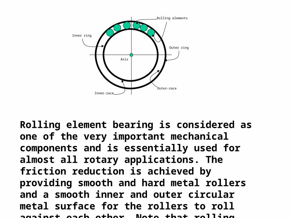
Outer ring
Inner ring
Rolling elements
Axis
Inner-race
Outer-race
Rolling element bearing is considered as one of the very important mechanical components and is essentially used for almost all rotary applications. The friction reduction is achieved by providing smooth and hard metal rollers and a smooth inner and outer circular metal surface for the rollers to roll against each other. Note that rolling reduces friction related energy loss to a minimum, ideally to zero.

Ball Cylindrical Needle Tapered Ball Cylindrical Needle Tapered
There are many types of bearings as far as rolling element is concerned. The geometric shape of these rolling elements define the classification. Commonly used rolling elements are,
Balls Cylindrical rollers Needle type rollers Tapered rollers

Radial load
Axial and radial load
Rolling bearingRadial load
Radial load
Radial load
SHAFT
Body
Body
The rolling element bearings consist of two circular metal (usually steel) rings and a set of rolling elements. One of the rings is larger than the other. The smaller of the two is called inner ring and the other one is referred to as the outer ring. The inner ring fits well within the perimeter of the outer ring. A fixed number of solid rollers, depending upon the load requirements are designed into geometric shapes and placed at equal intervals in the open space between the two rings.
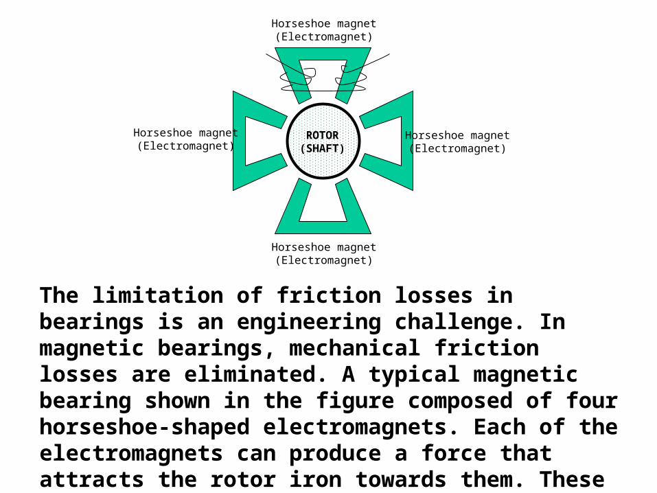
ROTOR(SHAFT)
Horseshoe magnet(Electromagnet)
Horseshoe magnet(Electromagnet)
Horseshoe magnet(Electromagnet)
Horseshoe magnet(Electromagnet)
The limitation of friction losses in bearings is an engineering challenge. In magnetic bearings, mechanical friction losses are eliminated. A typical magnetic bearing shown in the figure composed of four horseshoe-shaped electromagnets. Each of the electromagnets can produce a force that attracts the rotor iron towards them. These bearings allow the rotating shaft to float on a magnetic field created by the electromagnet.

(a) (b)
Belt
Pulley
Axle
Axle
The pulley is a simple component consists of a plain or grooved wheel and a rope or belt wrapped around the wheel, mainly used to change the direction and the point of application of a pulling force. Depending upon the system requirements, design of several types of pulleys are considered. Pulleys can be combined to form double pulleys, which have at least two wheels. There are various other combinations, which can result in a triplex pulleys and complex pulleys.

Timing element
Belt (top view)
Axle Axle
Pulleys can be constructed to assure accurate positioning, repeatability, and drive performance. One type of pulleys are called timing pulleys which are mainly used for positioning applications.

Magnetic Pulley
In some applications magnetic pulleys are employed. The prime function of a magnetic pulley is for continuous extraction and separation of contamination such as unwanted iron particles, piece etc. from the mixture in order to protect the processing machinery such as crushers, grinders and other valuable equipment

Shaft
Gear-1
Gear-2
Teeth
Shaft
Axis
Gears are important mechanical components used in almost all machineries. They facilitate mechanism in terms of transformation of power and motion from one rotating shaft to another. They can help to increase or decrease force, torque or speed and can change the direction of the axis of rotation. They can also change rotary motion to linear motion.

Input
Output
Idler
The gears essentially work together at least in groups of two or more. A single pair may be inadequate for certain sources and loads, in which case more complex combinations, are necessary. More than two gears working together is called a gear train. They can mesh in many different ways depending upon the application requirements.

(a)
(b)
(c)
(d)
The way the teeth are designed classifies the gears. Basically, four types of gears are found in engineering applications, however, some derivatives from these are also designed.
Spur gearsBevel gearsHelical gears Worm gears

(a) (b)
3w
1w2w 4w
1w2w
3w
1
2
3
4
32 ww
The gear ratio is related to the ratio of the gears, as already mentioned, but usually it is defined as the ratio of speeds. The velocity ratio of the driver and follower does not change by putting any number of gears between them.
3
1
3
2
2
1
w
w
w
w
w
wR
4
1
4
3
3
2
2
1
w
w
w
w
w
w
w
wR

RACK
PINION
Rack and pinion driving mechanism refers to a special type of gearing mechanism in which the rotational motion is converted to linear one and vice versa.
(Courtesy Andantex USA, Inc.)

Ratchet wheel
Lever
Pawl
Ratchet wheel
Primary pawl
Supplementary pawlCrank
(a) (b)
Axle
ToothWheel
The ratchet is an asymmetric mechanical component that allows something to turn in one direction only. In conjunction with another component called pawl, fundamentally, as if the ratchet works like a locking system. It is designed with suitably shaped teeth, receiving an intermittent circular motion from another member, called crank.

Piston(Slider)
Cylinder
Shaft
Crank
Fuel
The slider-crank is a linkage that transforms linear motion to circular motion or vice versa. The crank is a lever attached to a rotating shaft. It is really a link, which revolves relative to a frame. The link can convert a rotating motion into a reciprocating motion or vice versa.

Dwell
Rise
Dwell
Fall
Dwell
Rise
Dwell
Fall
The displacement profile of the follower
Cam rotation
Cam axis
Dwell
Rise
Fall
O
A
D
G
B
CE
F
Cam rotation
Dwell
O
A
D
G
B
CE
F
Cam rotation
O
A
D
G
B
CE
F
Reference
Follower
Reference
D
C
B
A
O
E
F
G
CAM
FOLLOWERTranslational
motion
(a) (b)
(c)
O A B C D E F G O A
A cam is defined as a machine element having a curved surface, which, by its rotational motion, gives a predetermined specified motion to another element called the follower which always in contact with the cam. The irregul-arly shaped cam rotates in an eccentricalaxis. The mechanism is used to transmit reciprocal motion .
A typical cam and its displacement profile
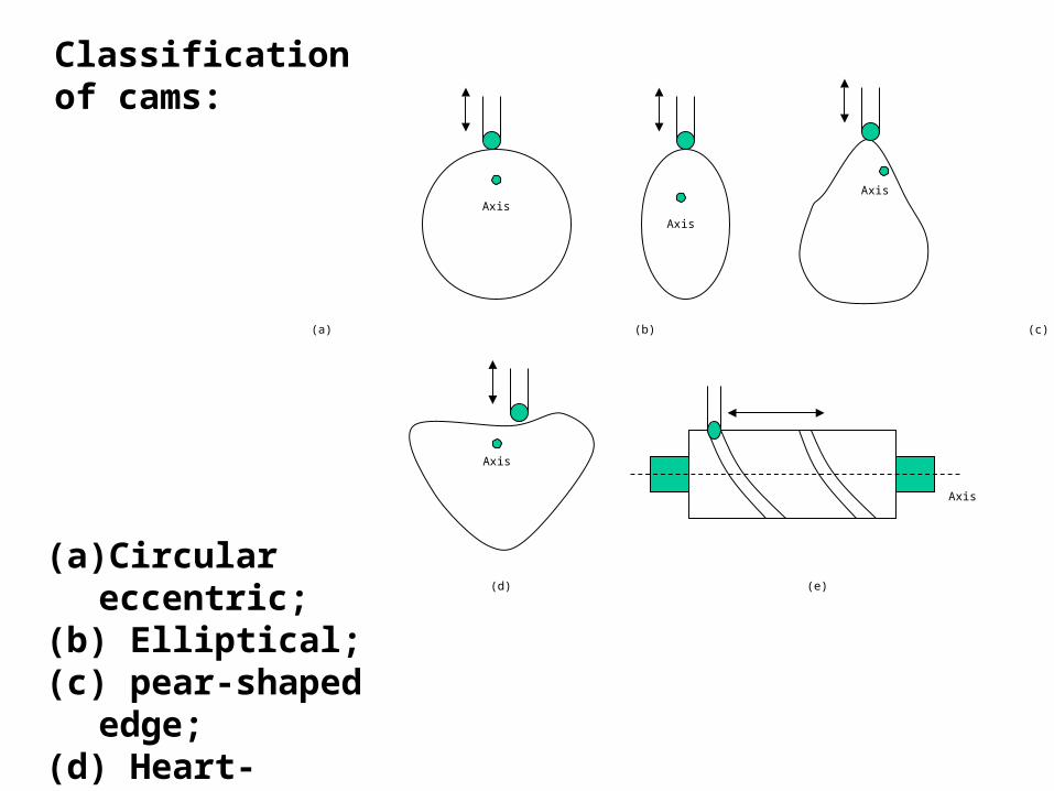
(a) (b) (c)
(d) (e)
Axis
Axis
AxisAxis
Axis
(a) Circular eccentric; (b) Elliptical;(c) pear-shaped edge; (d) Heart-shaped; (e) Cylindrical
Classification of cams:

Axis Axis Axis
(a) (b) (c)
Broadly, the shape of the followers is of three types; pointed follower, roller-type follower and the mushroom or flat foot follower. The pointed follower is designed with a knifelike edge or point. It is the simplest one and inherits drawbacks of rapid rate of wear. Roller-type followers incorporate rollers, a design that can improve reliability and performance. Roller-type followers overcomes the problem of rapid rate of wear and can withstand higher dynamic loads. Mushroom followers utilize a tappet that has a larger diameter base than the diameter of the body of the follower itself.

Sprocket
Sprocket
Chain
Chain
The chain and sprocket drive is another mechanical component, which is also exploited for power transmission. The sprocket is a toothed wheel and the chain is a loop of loosely jointed links (Figure-7.35). In operation, the chain-sprocket in combination offers the means of transmitting power between two or more rotating shafts.

Lower Wheel
Upper Wheel
Upper wheel axis of rotation
Lower wheel axis of rotation
Driving pin
Geneva wheel based mechanism is used for achieving intermittent motions. The component has two wheels, the upper and the lower wheel. There is a projection, called drive pin, mounted on the lower wheel. The rotational movement of the lower wheel is essentially continuous but the upper wheel only rotates step-wise i.e., intermittently. The upper wheel makes one complete rotation corresponding to four complete rotations of the lower wheel, in this typical example.

Position
O
C
A
B
12
3
422 , w
L-1
L-2
L-3
L-4
33 , w
44 , w
x
y
Four-bar linkage has four axes of rotation connected by four rigid linkages. Four-bar linkages have the capability of mimicking rotation, oscillation, and translation. The linkage is a versatile component used extensively in many machineries and system such as steering systems of almost all automobiles, the sewing machines, earth movers, packaging machines and so on.