Sensorless Pump Control for VLT 6000 HVAC / FCM 300...
22
Sensorless Pump Control for VLT ® 6000 HVAC / FCM 300 ■ Contents Functionality ..................................................................................................... 2 How Does It Work? ................................................................................................ 3 Limitations .............................................................................................................. 5 Parameter Setting - Head ....................................................................................... 6 Par. 705 Quadratic Head ........................................................................................ 6 Par. 707 Head Qmin .............................................................................................. 6 Par. 716 Head Working Point ................................................................................. 6 Par. 717 Flow Working Point .................................................................................. 7 Control Principle ............................................................................................. 8 Parameter Setting - Control .................................................................................... 10 Par. 701 Power Error .............................................................................................. 10 Par. 702 Delta Frequency ....................................................................................... 10 Par. 703 Integral Power .......................................................................................... 10 Par. 704 Integral Frequency ................................................................................... 10 Programming other Functionalities ...................................................... 11 Par. 708 Power Compensation .............................................................................. 11 Analog Output ........................................................................................................ 12 Par. 720 AO Max Value .......................................................................................... 12 Analog Input ........................................................................................................... 13 Read-outs in LCP ................................................................................................... 14 Power/Frequency Read-out ................................................................................... 15 VLT 6000 ................................................................................................................ 16 Measuring Values ........................................................................................... 17 Introduction ............................................................................................................ 17 Installation and Setup of the Software .................................................................... 17 Installation .............................................................................................................. 17 Entering Pump Data ............................................................................................... 18 Number of Measurements ...................................................................................... 20 Other Functionalities of the Program ....................................................................... 20 Data and Read-outs ............................................................................................... 21 MG.10.T1.02 - VLT is a registered Danfoss trademark 1
Transcript of Sensorless Pump Control for VLT 6000 HVAC / FCM 300...

Sensorless Pump Control for VLT® 6000 HVAC / FCM 300
■ Contents
Functionality ..................................................................................................... 2How Does It Work? ................................................................................................ 3Limitations .............................................................................................................. 5Parameter Setting - Head ....................................................................................... 6Par. 705 Quadratic Head ........................................................................................ 6Par. 707 Head Qmin .............................................................................................. 6Par. 716 Head Working Point ................................................................................. 6Par. 717 Flow Working Point .................................................................................. 7
Control Principle ............................................................................................. 8Parameter Setting - Control .................................................................................... 10Par. 701 Power Error .............................................................................................. 10Par. 702 Delta Frequency ....................................................................................... 10Par. 703 Integral Power .......................................................................................... 10Par. 704 Integral Frequency ................................................................................... 10
Programming other Functionalities ...................................................... 11Par. 708 Power Compensation .............................................................................. 11Analog Output ........................................................................................................ 12Par. 720 AO Max Value .......................................................................................... 12Analog Input ........................................................................................................... 13Read-outs in LCP ................................................................................................... 14Power/Frequency Read-out ................................................................................... 15VLT 6000 ................................................................................................................ 16
Measuring Values ........................................................................................... 17Introduction ............................................................................................................ 17Installation and Setup of the Software .................................................................... 17Installation .............................................................................................................. 17Entering Pump Data ............................................................................................... 18Number of Measurements ...................................................................................... 20Other Functionalities of the Program ....................................................................... 20Data and Read-outs ............................................................................................... 21
MG.10.T1.02 - VLT is a registered Danfoss trademark 1
Sensorless Pump Control for VLT® 6000 HVAC / FCM 300
■ Functionality
Sensorless Pump Control (Sensorless) has beendeveloped to enable the drive to control the pressure(Head) in a circuit with non-compressible liquid,e.g. water, WITHOUT using a pressure transducer.This has several advantages such as:
• Cost savings as there is no need for apressure transducer.
• Increased reliability, as there are no additionalcomponents (transducer, cable, connections)that can cause malfunction.
• No maintenance and exchange of pressuretransmitters.
• Very dynamic with a response time ofonly 1-2 seconds.
• Increased energy savings.
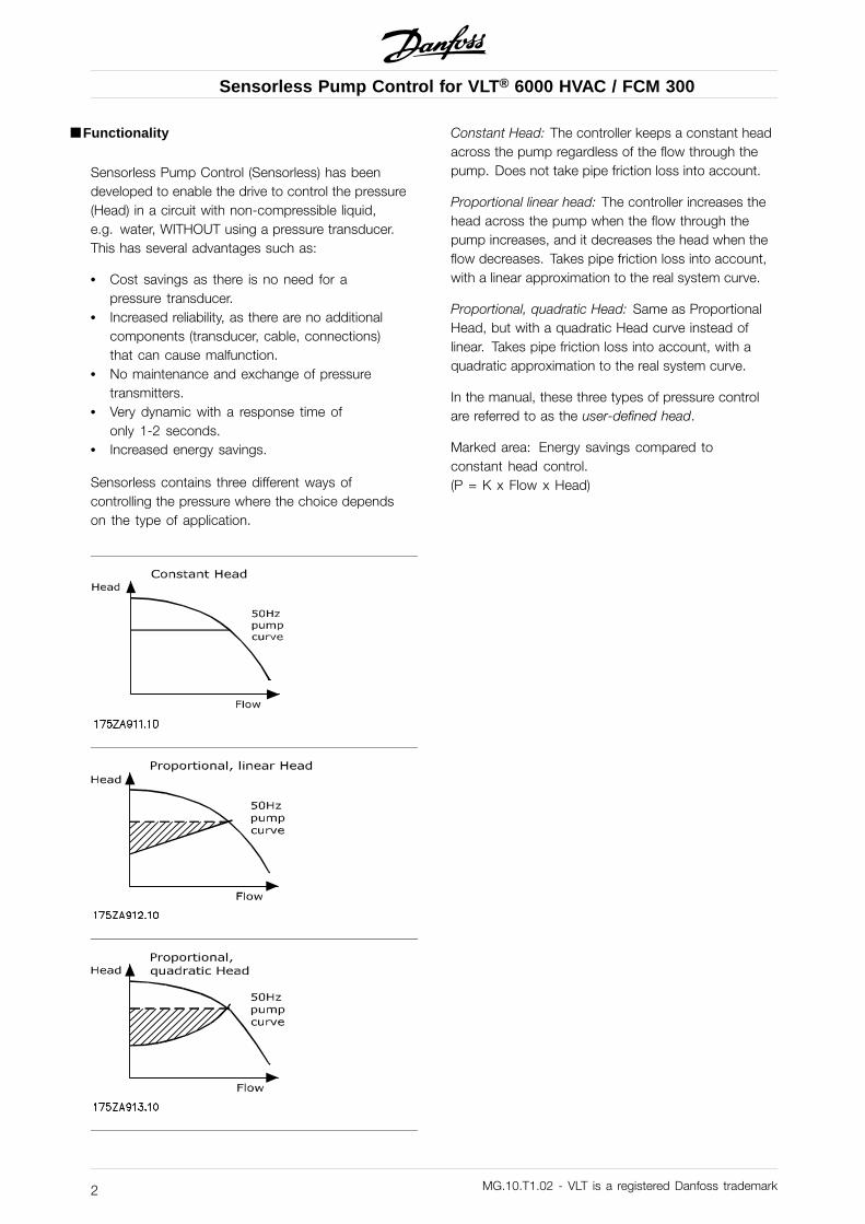
Sensorless contains three different ways ofcontrolling the pressure where the choice dependson the type of application.
Constant Head: The controller keeps a constant headacross the pump regardless of the flow through thepump. Does not take pipe friction loss into account.
Proportional linear head: The controller increases thehead across the pump when the flow through thepump increases, and it decreases the head when theflow decreases. Takes pipe friction loss into account,with a linear approximation to the real system curve.
Proportional, quadratic Head: Same as ProportionalHead, but with a quadratic Head curve instead oflinear. Takes pipe friction loss into account, with aquadratic approximation to the real system curve.
In the manual, these three types of pressure controlare referred to as the user-defined head.
Marked area: Energy savings compared toconstant head control.(P = K x Flow x Head)
MG.10.T1.02 - VLT is a registered Danfoss trademark2

Sensorless Pump Control for VLT® 6000 HVAC / FCM 300
Fun
ctio
nalit
y
■ How Does It Work?
Sensorless is based on the relations between frequency, flow, head and power. So consequently the driveneeds the data shown in the graphs below as input for the calculations. The data are pump specific and needto be found by measurement. Alternatively, the data can be found by data sheet from the pump supplier ifaccurate enough.The graph below shows an example of some measured values for flow/head on a typical centrifugal pump.
Head/flow (H/Q) Curves on a 1.5 kW pump
The graph below shows the measured values for flow/power.
Power/flow (P/Q) Curves on a 1.5 kW pump
MG.10.T1.02 - VLT is a registered Danfoss trademark 3
Sensorless Pump Control for VLT® 6000 HVAC / FCM 300
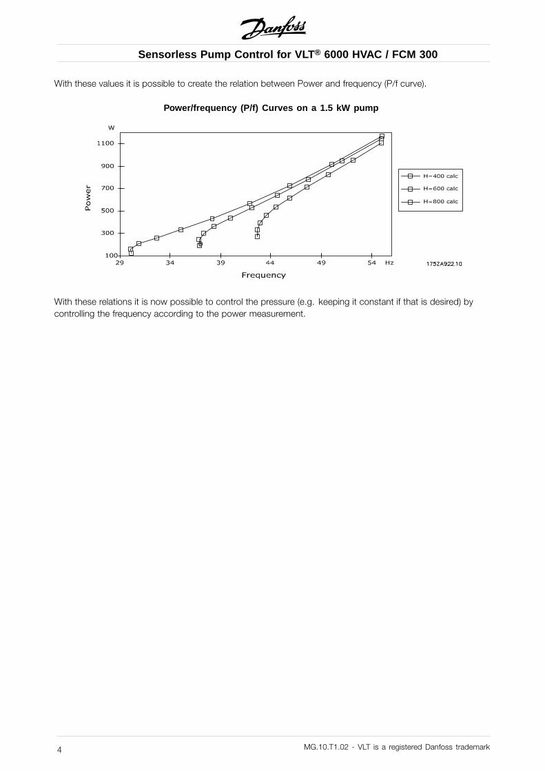
With these values it is possible to create the relation between Power and frequency (P/f curve).
Power/frequency (P/f) Curves on a 1.5 kW pump
With these relations it is now possible to control the pressure (e.g. keeping it constant if that is desired) bycontrolling the frequency according to the power measurement.
MG.10.T1.02 - VLT is a registered Danfoss trademark4

Sensorless Pump Control for VLT® 6000 HVAC / FCM 300
Fun
ctio
nalit
y
■ LimitationsA criteria for Sensorless to work is that there must be aclear one-to-one relation between head and flow, andpower and flow, (i.e. only one H-value to one Q-valueand opposite) as this forms the basis for the P/f-curve.
Sensorless can be used with centrifugal pumpsthat have radial impeller. On pumps with mixedflow impellers there is only limited use as the powercurve is typically flat at high flow rates. A centrifugalpump with axial impeller cannot be controlled withsensorless control due to the particular shape ofthe head curve. The graphics below show typicalcharacteristics for the different pump types.
Radial impellernq=20 min-1
Possible
Mixed flow impellernq=80 min-1
Limited
Axial impellernq=200 min-1
Not possible
Other limitations: Sensorless control is limited tonon-compressible liquids such as water. Furthermorethe solution is recommended only in closed systems.
MG.10.T1.02 - VLT is a registered Danfoss trademark 5

Sensorless Pump Control for VLT® 6000 HVAC / FCM 300
This parameter activates the Sensorless control:Par. No. Par. Name Selection Default DescriptionPar. 700 (SENSOR-
LESS CON-TROL)
FCM: OFF/ONVLT 6000:ENABLE/DISABLE
OFF/DISABLE Set parameter to enable/ONto activate Sensorless control.Please observe that this parametermust be set to disable when doingmeasurements.
The following parameters must be set to make Sensorless work:VLT 6000 FCMPar. 100 must be OPEN LOOP Par. 003 must be LOCALPar. 101 must be MULTIPLE MOTORS Par. 100 must be OPEN LOOP- Par. 101 must be VT HIGH
The following parameters determine the user-definedhead for the system.
■ Par. 705 Quadratic HeadPar. 705 Quadratic head
(QUADRATIC HEAD)
Value:ON/OFF ✭ OFF
Function:Used when selecting the desired type ofSensorless control: Quadratic head or linear(proportional or constant) head.
Description of choice:
OFF: Generates a linear head/flow reference betweenHead Qmin (Par. 707) and Head working point (Par. 716).ON: Generates a quadratic head/flow referencebetween Head Qmin (Par. 707) and Headworking point (Par. 716)
■ Par. 707 Head QminPar. 707 Head Qmin
(HEAD QMIN)
Value:0-100% ✭ 100%
Function:Sets the head reference at zero flow as a percentageof the value specified in Par. 716.
Description of choice:
Set a value between 0 and 100%.
MG.10.T1.02 - VLT is a registered Danfoss trademark6
Sensorless Pump Control for VLT® 6000 HVAC / FCM 300
Fun
ctio
nalit
y
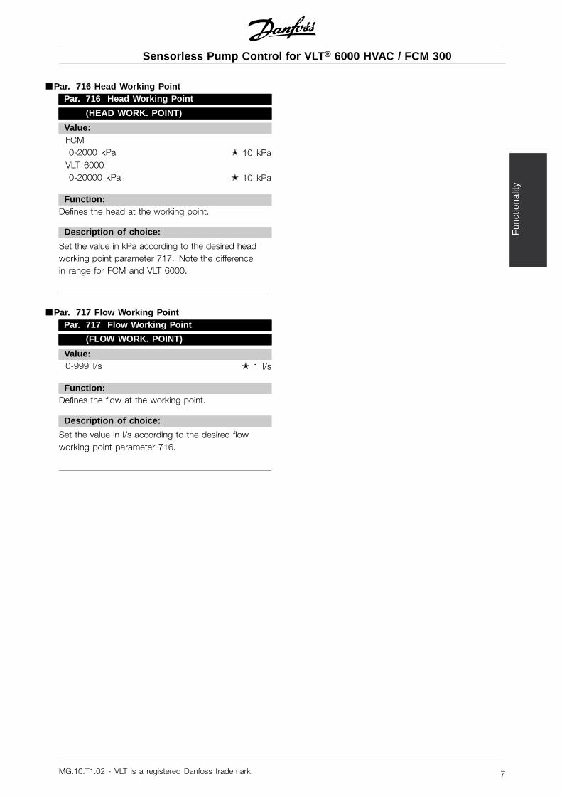
■ Par. 716 Head Working PointPar. 716 Head Working Point
(HEAD WORK. POINT)
Value:FCM0-2000 kPa ✭ 10 kPa
VLT 60000-20000 kPa ✭ 10 kPa
Function:Defines the head at the working point.
Description of choice:
Set the value in kPa according to the desired headworking point parameter 717. Note the differencein range for FCM and VLT 6000.
■ Par. 717 Flow Working PointPar. 717 Flow Working Point
(FLOW WORK. POINT)
Value:0-999 l/s ✭ 1 l/s
Function:Defines the flow at the working point.
Description of choice:
Set the value in l/s according to the desired flowworking point parameter 716.
MG.10.T1.02 - VLT is a registered Danfoss trademark 7

Sensorless Pump Control for VLT® 6000 HVAC / FCM 300
■ Control Principle
The control principle builds on converting an internal feedback of inverter parameters into a power referencethat the controller uses to adjust the output frequency. The control scheme is illustrated below.
The control part is divided into two parts:
•The Integration control part sums up the actual power error and whenever the threshold definedPower error (par. 701)
as the valueIntegral Power (par. 703)
is exceeded, the actual speed is increased resp.
Delta freq. (par. 702)decreased with the value xIntegral freq. (par. 704)
•The Three point control part uses par. 701 to define the threshold. If the deviation to the actualpower setpoint exceeds the value in par. 701, the speed increases respectively decreases withthe value in par. 702.
For VLT 6000 the updating takes place every 160ms and for FCM every 20ms.
MG.10.T1.02 - VLT is a registered Danfoss trademark8

Sensorless Pump Control for VLT® 6000 HVAC / FCM 300
Con
trol
Prin
cipl
e
MG.10.T1.02 - VLT is a registered Danfoss trademark 9
Sensorless Pump Control for VLT® 6000 HVAC / FCM 300
■ Parameter Setting - ControlThe following parameters are used for settingup the control:
■ Par. 701 Power ErrorPar. 701 Power Error
(POWER ERROR)
Value:FCM: 1-50W ✭ 20WVLT 6000: 1-250W ✭ 20W
Function:See description under "Control Principle".
Description of choice:
A small value leads to a lower threshold for theintegration part of the controller, and thereby fasterreaction. Larger pumps will require a larger value.
■ Par. 702 Delta FrequencyPar. 702 Delta Frequency
(DELTA FREQUENCY)
Value:0,1-1 Hz ✭ 0,4 Hz
Function:See description under "Control Principle".
Description of choice:
A small value leads to a smaller frequency stepin the integration control part. This means slowerbut more precise control.
■ Par. 703 Integral PowerPar. 703 Integral Power
(INTEGRAL POWER)
Value:1-100 ✭ 20
Function:See description under "Control Principle".
Description of choice:
A small value leads to a higher thresholdfor the integration part of the controller, andthereby faster reaction.
■ Par. 704 Integral FrequencyPar. 704 Integral Frequency
(INTEGRAL FREQUENCY)
Value:1-100 ✭ 20
Function:See description under "Control Principle".
Description of choice:
A small value leads to a larger frequency stepin the three-point control part. This meansfaster but rougher control.
MG.10.T1.02 - VLT is a registered Danfoss trademark10

Sensorless Pump Control for VLT® 6000 HVAC / FCM 300
Pro
gram
min
g ot
her
Fun
ctio
nalit
ies
■ Power Compensation
Par. 708 Power Compensation
(POWER COMP)
Value:VLT 6000: -1000W-1000W ✭ 0FCM: -100W-100W ✭ 0
Function:To obtain a more precise control and read-out, it can bean advantage to correct the total power in the P/f tableby an offset, positive or negative. Example on effect:On a 1½ kW pump, about -30W can change the flowread-out from 2.2 l/s to 1.8l/s. at max flow of 10 l/s.
Description of choice:
When preparing the system for sensorless control,compare the calculated flow values with real measuredvalues. If there is a deviation in figures, this canbe caused by an offset in values. Enter the valuenecessary to obtain as small a deviation as possible.
MG.10.T1.02 - VLT is a registered Danfoss trademark 11

Sensorless Pump Control for VLT® 6000 HVAC / FCM 300
■ Analog Output
Terminal 45 on the VLT 6000 and terminal 9 on theFCM can be used to read out either flow or head.
VLT 6000:Par. 321 Terminal 45, output
FCM:Par. 304 Terminal 9, output
ValueThe following choices have been added:Choice Choice no. FCM Choice no. VLT 6000SENS. FLOW = 0-20 mA [22] [44]SENS. FLOW = 4-20 mA [23] [45]SENS. HEAD = 0-20 mA [24] [46]SENS. HEAD = 4-20 mA [25] [47]
■ Par. 720 AO Max ValuePar. 720 AO Max Value
(AO MAX VALUE)
Value:1-9999 ✭ 1
Function:This parameter is used to convert the currentsignal to a head or flow value.
Description of choice:
Enter the maximum value for head or flow, at whichthe analog output must give 20 mA.Example:Par. 321 is SENS. HEAD = 4-20 mAPar. 720 is 200 (kPa)The actual head is 100kPa. That bringsterminal 45 up to 12mA.
MG.10.T1.02 - VLT is a registered Danfoss trademark12

Sensorless Pump Control for VLT® 6000 HVAC / FCM 300
Pro
gram
min
g ot
her
Fun
ctio
nalit
ies
■ Analog InputIt is possible to reduce the user-defined headwith the following parameters.
Drive Input Parameter Choice ValueFCM DI 9 332 [38] SENSORLESSVLT 6000 AI 53 308 [10] SENSORLESS HEAD
Function: The analog input can be used to reducethe user-defined head Q with a desired percentage.Using a 0-10 V potentiometer means that 0 V equals0% and 10 V equals 100%. So if a 25% reductionis desired, set the potentiometer to 2.5 V.
MG.10.T1.02 - VLT is a registered Danfoss trademark 13
Sensorless Pump Control for VLT® 6000 HVAC / FCM 300
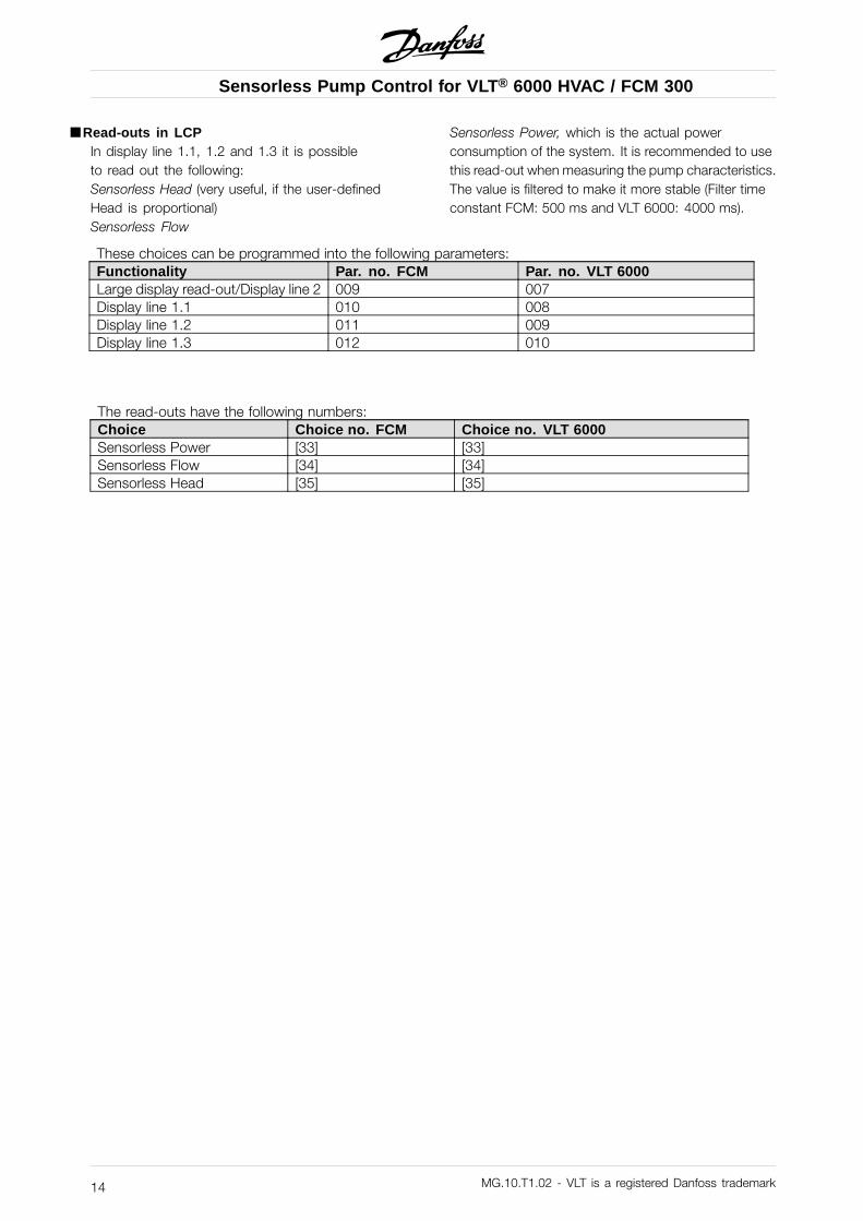
■ Read-outs in LCPIn display line 1.1, 1.2 and 1.3 it is possibleto read out the following:Sensorless Head (very useful, if the user-definedHead is proportional)Sensorless Flow
Sensorless Power, which is the actual powerconsumption of the system. It is recommended to usethis read-out when measuring the pump characteristics.The value is filtered to make it more stable (Filter timeconstant FCM: 500 ms and VLT 6000: 4000 ms).
These choices can be programmed into the following parameters:Functionality Par. no. FCM Par. no. VLT 6000Large display read-out/Display line 2 009 007Display line 1.1 010 008Display line 1.2 011 009Display line 1.3 012 010
The read-outs have the following numbers:Choice Choice no. FCM Choice no. VLT 6000Sensorless Power [33] [33]Sensorless Flow [34] [34]Sensorless Head [35] [35]
MG.10.T1.02 - VLT is a registered Danfoss trademark14
Sensorless Pump Control for VLT® 6000 HVAC / FCM 300
Pro
gram
min
g ot
her
Fun
ctio
nalit
ies
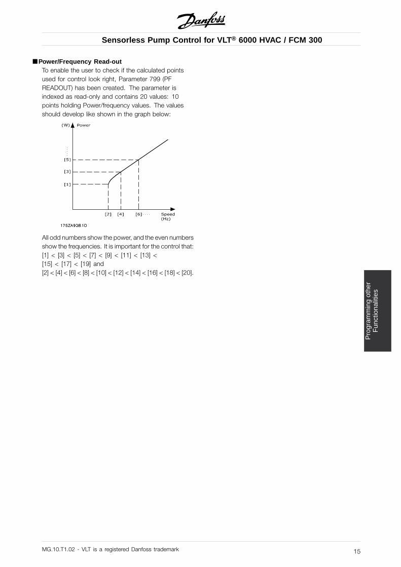
■ Power/Frequency Read-outTo enable the user to check if the calculated pointsused for control look right, Parameter 799 (PFREADOUT) has been created. The parameter isindexed as read-only and contains 20 values: 10points holding Power/frequency values. The valuesshould develop like shown in the graph below:
All odd numbers show the power, and the even numbersshow the frequencies. It is important for the control that:[1] < [3] < [5] < [7] < [9] < [11] < [13] <[15] < [17] < [19] and[2] < [4] < [6] < [8] < [10] < [12] < [14] < [16] < [18] < [20].
MG.10.T1.02 - VLT is a registered Danfoss trademark 15
Sensorless Pump Control for VLT® 6000 HVAC / FCM 300
■ VLT 6000Please note that the choice in parameter 300 "selectionof MSB" has been removed, and consequentlyonly 2 setups are available.
MG.10.T1.02 - VLT is a registered Danfoss trademark16

Sensorless Pump Control for VLT® 6000 HVAC / FCM 300
Mea
surin
gV
alue
s
■ Measuring Values
■ Introduction
This instruction concerns the use of SControl for Sensorless Pump Control for VLT 6000 and FCM 300. Pleasecontact Danfoss to acquire the SControl Software.
■ Installation and Setup of the Software
SControl operates in two modes:• Production mode
This mode is used in production in cases where pump data are not supposed to be changed. A pump canbe chosen and data can be downloaded to the drive.
• Edit modeThis mode is used when entering different pump data, adding and removing pumps. Also in this mode,data can be downloaded to the drive.
Please note that only the command buttons show which mode is active.
■ Installation
Run the "Setup.exe" file and the program will be installed. Only the Production Mode is installed in the firststep. In order to install the Edit mode, create a short-cut of the program and type " edit" at the end of thepath: "C:\Program Files\Danfoss Drives\SControl\Scontrol.exe" edit Remember to include a space beforeedit; otherwise it will not work.
MG.10.T1.02 - VLT is a registered Danfoss trademark 17

Sensorless Pump Control for VLT® 6000 HVAC / FCM 300
■ Entering Pump Data
To add a pump: Push the command button +To remove a pump: Push the command button -
If the pump is connected to a VLT 6000, write VLT6*** in the pump type followed by the pump type.
For entering data, choose Database Editor.Enter frequencies (one or more) in the left column. Start with the highest value. More frequencies can beadded later.
MG.10.T1.02 - VLT is a registered Danfoss trademark18

Sensorless Pump Control for VLT® 6000 HVAC / FCM 300
Mea
surin
gV
alue
s
Select one frequency and add flow/power/head values for that specific frequency. Start with no flow. It isimportant to have the same order as this:
MG.10.T1.02 - VLT is a registered Danfoss trademark 19

Sensorless Pump Control for VLT® 6000 HVAC / FCM 300
■ Number of Measurements
The specified accuracy of Sensorless Pump Control (maximum 5% deviation) is based on having 100measurements (10 frequencies and 10 flow/power and head measurements for each frequency). The minimumnumber is 16 measurements (flow/power/head values) for at least 4 frequencies.
The program also has a functionality called "Auto Insert Data". It is only necessary to use this functionality with10 measurements for 1 frequency, and the program will calculate the remaining points.
Please note that using less than 100 measurements will decrease the accuracy. Therefore check the accuracyafter programming and make sure that it is within an acceptable level.
Step by step1. Put the drive at fixed speed.2. Find max flow (do not write it into SControl)3. Measure Power/Head at 0 flow, write data in SControl.4. Spread the flow measurements evenly in 10 steps, from 0 to max flow, and enter Power/Head/Flow
values into SControl (see example above).5. Do the measurements for 10 frequency steps evenly spread between Fmax and Fmin (unless using
less than 100 measurements as described above).
■ Other Functionalities of the Program
Pressing the "VLT parameters" command button, you can enter desired values for parameters. Whendownloading data to the drive, the listed parameters will be changed according to the entered values. Thedefault setting of these parameters can be changed in "Setup" and "Default VLT Parameter Setting".
NOTE: The parameters in FCM and VLT 6000 HVAC are different, so it is not possible to make a general list.
Pressing the "Download Data" and "Start" button will start downloading of pump data and parameter settingsinto the drive.
MG.10.T1.02 - VLT is a registered Danfoss trademark20
Sensorless Pump Control for VLT® 6000 HVAC / FCM 300
Mea
surin
gV
alue
s
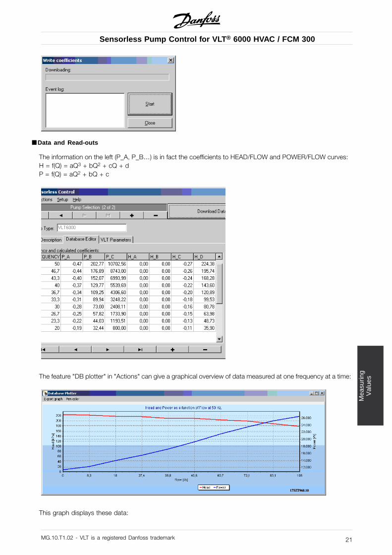
■ Data and Read-outs
The information on the left (P_A, P_B…) is in fact the coefficients to HEAD/FLOW and POWER/FLOW curves:H = f(Q) = aQ3 + bQ2 + cQ + dP = f(Q) = aQ2 + bQ + c
The feature "DB plotter" in "Actions" can give a graphical overview of data measured at one frequency at a time:
This graph displays these data:
MG.10.T1.02 - VLT is a registered Danfoss trademark 21

Sensorless Pump Control for VLT® 6000 HVAC / FCM 300
If more data have been entered for other frequencies, simply select the other frequency without closingthe plotter window.
Use "Export to Excel" to copy all data to the Excel sheet that comes with the installation of Scontrol: Open theExcel sheet "Sensorless Plot" and place the marker at cell A1, and choose "Edit" and "Paste".
MG.10.T1.02 - VLT is a registered Danfoss trademark22