Sensor Starter Kit User Guide - Vishay Intertechnology Starter Kit User Guide APPLICATION NOTE...
17
VISHAY SEMICONDUCTORS Optical Sensors Application Note Sensor Starter Kit User Guide APPLICATION NOTE Revision: 18-Aug-14 1 Document Number: 84264 For technical questions, contact: [email protected] THIS DOCUMENT IS SUBJECT TO CHANGE WITHOUT NOTICE. THE PRODUCTS DESCRIBED HEREIN AND THIS DOCUMENT ARE SUBJECT TO SPECIFIC DISCLAIMERS, SET FORTH AT www.vishay.com/doc?91000 www.vishay.com By Reinhard Schaar INTRODUCTION With the first digital sensors featuring the possibility to be controlled via the I 2 C-bus Vishay offered a demo kit that allowed for an easy connection to any Windows PC. This demo kit was for the very first proximity / ambient light sensor (VCNL4000) and it looked as follows: Fig. 1 - VCNL4000 Demo Kit This VCNL4000 demo kit came with a mini-CD containing the USB driver and software, a USB dongle and the VCNL4000 sensor board. This kit has now been replaced with the Sensor Starter Kit. Fig. 2 - Sensor Starter Kit The Sensor Starter Kit includes a USB dongle and mini-CD, which includes the needed USB driver and updated software. This is now the base for all of Vishay’s sensor boards. This kit (order name: SensorStarterKit) can be purchased from any of our catalogue distributors. It serves as the base for the VCNL4010, VCNL4020, VCNL4020X01, and VCNL3020 sensor boards and the VCNL4020 gesture demo board. Every new digital sensor will also be available on a new sensor board, which can be connected to the USB dongle and operated with the Sensor Starter Kit software.
Transcript of Sensor Starter Kit User Guide - Vishay Intertechnology Starter Kit User Guide APPLICATION NOTE...

V I S H A Y S E M I C O N D U C T O R S
Optical Sensors Application Note
Sensor Starter Kit User Guide
AP
PL
ICA
TIO
N N
OT
E
Revision: 18-Aug-14 1 Document Number: 84264
For technical questions, contact: [email protected] DOCUMENT IS SUBJECT TO CHANGE WITHOUT NOTICE. THE PRODUCTS DESCRIBED HEREIN AND THIS DOCUMENT
ARE SUBJECT TO SPECIFIC DISCLAIMERS, SET FORTH AT www.vishay.com/doc?91000
www.vishay.com
By Reinhard Schaar
INTRODUCTIONWith the first digital sensors featuring the possibility to be controlled via the I2C-bus Vishay offered a demo kit that allowed for an easy connection to any Windows PC.
This demo kit was for the very first proximity / ambient light sensor (VCNL4000) and it looked as follows:
Fig. 1 - VCNL4000 Demo Kit
This VCNL4000 demo kit came with a mini-CD containing the USB driver and software, a USB dongle and the VCNL4000 sensor board.
This kit has now been replaced with the Sensor Starter Kit.
Fig. 2 - Sensor Starter Kit
The Sensor Starter Kit includes a USB dongle and mini-CD, which includes the needed USB driver and updated software. This is now the base for all of Vishay’s sensor boards.
This kit (order name: SensorStarterKit) can be purchased from any of our catalogue distributors. It serves as the base for the VCNL4010, VCNL4020, VCNL4020X01, and VCNL3020 sensor boards and the VCNL4020 gesture demo board.
Every new digital sensor will also be available on a new sensor board, which can be connected to the USB dongle and operated with the Sensor Starter Kit software.
Sensor Starter Kit User Guide
AP
PL
ICA
TIO
N N
OT
EApplication Note
www.vishay.com Vishay Semiconductors
Revision: 18-Aug-14 2 Document Number: 84264
For technical questions, contact: [email protected] DOCUMENT IS SUBJECT TO CHANGE WITHOUT NOTICE. THE PRODUCTS DESCRIBED HEREIN AND THIS DOCUMENT
ARE SUBJECT TO SPECIFIC DISCLAIMERS, SET FORTH AT www.vishay.com/doc?91000
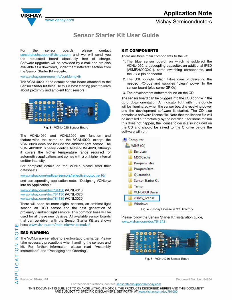
For the sensor boards, please contact [email protected] and we will send you the requested board absolutely free of charge. Software upgrades will be provided by e-mail and are also available as a download, under the “Software” section from the Sensor Starter Kit website:
www.vishay.com/moreinfo/vcnldemokit/
The VCNL4020 is the default sensor board attached to the Sensor Starter Kit because this is best starting point to learn about proximity and ambient light sensors.
Fig. 3 - VCNL4020 Sensor Board
The VCNL4010 and VCNL3020 are function and feature-wise the same as the VCNL4020, except the VCNL3020 does not include the ambient light sensor. The VCNL4020X01 is nearly identical to the VCNL4020, although it covers the higher temperature range required for automotive applications and comes with a bit higher internal emitter intensity.
For complete details on the VCNLs please read their datasheets
www.vishay.com/optical-sensors/reflective-outputis-16/
and corresponding application notes “Designing VCNLxyz into an Application”:
www.vishay.com/doc?84138 (VCNL4010) www.vishay.com/doc?84136 (VCNL4020) www.vishay.com/doc?84139 (VCNL3020)
There will soon be more digital sensors, an ambient light sensor, an RGB sensor and the next generation of proximity / ambient light sensors. This common base will be used for all these new devices. All available sensor boards that can be driven with the Sensor Starter Kit are shown here: www.vishay.com/moreinfo/vcnldemokit/
ESD WARNINGThe VCNLs are sensitive to electrostatic discharge. Please take necessary precautions when handling the sensors and kit. For further information please read “Assembly Instructions” and “Packaging and Ordering”.
KIT COMPONENTSThere are three main components to the kit:
1. The blue sensor board, on which is soldered the VCNL4020, a decoupling capacitor, an additional IRED (VSMF2890GX01), some switching components, and the 2 x 8 pin connector
2. The USB dongle, which takes care of delivering the needed I2C-bus and supplies “clean” power to the sensor board (plus some GPIOs)
3. The development software found on the CD
The sensor board can be plugged into the USB dongle in the up or down orientation. An indicator light within the dongle will be illuminated when the sensor board is receiving power and the development software is started. The CD also contains a software license file. Note that the license file will be installed automatically by the installer. If for some reason this does not happen, the license folder is also included on the CD and should be saved to the C: drive before the software will run:
Fig. 4 - Vishay License in C:/ Directory
Please follow the Sensor Starter Kit installation guide, www.vishay.com/doc?84242
Fig. 5 - VCNL4010 Sensor Board

Sensor Starter Kit User Guide
AP
PL
ICA
TIO
N N
OT
EApplication Note
www.vishay.com Vishay Semiconductors
Revision: 18-Aug-14 3 Document Number: 84264
For technical questions, contact: [email protected] DOCUMENT IS SUBJECT TO CHANGE WITHOUT NOTICE. THE PRODUCTS DESCRIBED HEREIN AND THIS DOCUMENT
ARE SUBJECT TO SPECIFIC DISCLAIMERS, SET FORTH AT www.vishay.com/doc?91000
VCNL Sensor Board Layout
The VCNL sensor boards, figure 3 and 5, have test points to allow simple evaluation and / or connection to the customer’s application board. The boards also include an external emitter (VSMF2890GX01) to increase the measurement range to 500 mm and supporting FETs to use the integrated emitter and external emitter in series.
For more information on extending the detection range, please read www.vishay.com/doc?84225
Sensor Board Description, Functions, and Features, as well as a Schematic of the Board
For the VCNL4020 gesture control sensor board, this information can be found at: www.vishay.com/doc?84218
Every new sensor board can be connected to the Sensor Starter Kit. Please see: www.vishay.com/moreinfo/vcnldemokit/
and the last page of this document.
Other Useful Links
I2C specification version 3.0:
www.nxp.com/documents/user_manual/UM10204.pdf
Male pin connector 2199SB-XXG-301523
Female pin connector 2200SB-XXG-A1
www.almita-connectors.com/connector/pcb-connectors.html
VCNL40x0 Development Software
After installing the software, run the following command: Rapid_VCNL40x0.exe. When executing the program, the Proximity Function screen is displayed. There are four tabbed files: Proximity Function, Ambient Light Function, Setup, and Register.
PROXIMITY FUNCTION
Proximity Mode
- select a single measurement, periodic measurement, or self-timed measurement. The periodic measurement rates are set in the Measurement Speed window within Setup menu. The default setting is “periodic measurement (on demand).” Selecting periodic measurement sets the ‘prox_od’ bit 3 of the command register #0 (80h) to “1.” See screen shot 1. When chosen “selftimed mode” one additional window will appear what allows then the to program the proximity rate between 1.95 and 250 measurements per second as specified within datasheet: proximity rate register #2 (82h) bits 0 to 2.
Proximity Settings
- sets the infrared emitter current. The infrared emitter current determines the effective range of the sensor; higher current will translate to longer sensing range. This feature can also be used to determine the impact of the cover or window on the sensing range. To compensate for the infrared light absorbed by the window, the current can be increased. The current can be set by either toggling up or down or by left clicking in the window and a current select bar will pop-up. The default setting is 100 mA.
Proximity Results
- shows the chosen measurement rate, which is dependent on the delay time selected in conjunction with the measurement speed. The default is 10 ms (“10”), which results in about 30 measurements per second. So the time needed for one measurement is 1/30 s = 0.033 s, which is shown within the “Measurement Time / Sample” field. The next four items show the actual proximity counts, their max., min., and mean values as well as the averaged peak to peak noise value.
Clear Display- clears the upper and lower window graphs and resets the
‘Data#’ to zero.
Proximity ValueChanges the unit of measure for the proximity value. Click on the small blue letter on its left side. This letter indicates the selected format: b = binary, d = decimal, x = hexadecimal, o = octal, and p stands for SI notation.
Infinite Impulse Response (IIR) FilterThis low pass filter is activated with the “active” button and shows an average of the measurement results. The average value can be changed from 1 to 20 by clicking on the toggle arrow where 1 corresponds to no averaging and 20 to strong averaging. When active the button will be red.
Upper WindowDisplays the entire 16-bit measured signal from 0 to 65 535 counts.
Lower WindowDisplays only the active or dynamic range. The y-axis represents the number of counts and will change depending on the sensor reading.
Proximity MeasurementClick on the measure button to initiate a measurement.

Sensor Starter Kit User Guide
AP
PL
ICA
TIO
N N
OT
EApplication Note
www.vishay.com Vishay Semiconductors
Revision: 18-Aug-14 4 Document Number: 84264
For technical questions, contact: [email protected] DOCUMENT IS SUBJECT TO CHANGE WITHOUT NOTICE. THE PRODUCTS DESCRIBED HEREIN AND THIS DOCUMENT
ARE SUBJECT TO SPECIFIC DISCLAIMERS, SET FORTH AT www.vishay.com/doc?91000
Screen Shot 1
Offset
Without an object in range, the upper window shows an offset of approximately 2000 counts. The lower windows shows the exact values. This offset is a result of optical crosstalk and digital noise. In an application where a window is placed over the top of the sensor, the offset value can be as high as 5000 to 20 000 counts.
For the kit, the offset value is calculated by averaging the last 2 seconds of counts. In a ready-made application the offset value should be subtracted from incoming proximity readings and the resultant used to determine object proximity.
Object with Range of 200 mm and 100 mm
Assuming the offset value is 2170 counts, at a range of 200 mm, the reflection from a hand results in an output count of 2190 counts. This is 20 counts higher than the offset or noise floor. At a range of 100 mm, the reflection of the object results in an output count of 2270 counts. This is 100 counts higher than the offset value. By clicking the “Compensate Offset” button, the software simulates this subtraction. When this function is active, the button will be red as in screen shot 1. With compensation offset active, the digital signal in the lower frame will display only the counts related to the reflected signal, effectively zeroing the offset. This is a feature of the kit only. In actual applications, the offset value should be subtracted to obtain actual proximity or ambient counts.
Object with Range of 10 mm and 5 mm
With compensation offset active, at a range of 10 mm, the reflection of the object (hand) results in an output count of approximately 8000 counts. At a range of 5 mm, the reflection results in an output count of approximately 30 000 counts. Again, with compensation offset active, the digital signal in the lower frame shows only the counts related to the reflected signal.
Display Range
Displays a specific range of readings by entering a minimum reading number on the right side of the x-axis and the maximum reading number on the left side of the x-axis. Type over the existing displayed value. This feature is only available when measurements have stopped.
Register Values
The actual proximity value is available by selecting the Register Value tab. The high 16-bit value is stored in register #7 and the low value is stored in register #8. Register #7 equals 8 (dec) [00001000] and register #8 equals 114 (dec) [01110010]. See screen shot 2.
Periodic measurement (on demand)Single measurement (on demand)Selftimed mode
Proximity Rate(only available for seftimed mode)(
Proximity values
On / off compensation
Low pass filter set on / off
Start / stop Measurement
Upper window
lower window
Set display range
Measurement rate and time

Sensor Starter Kit User Guide
AP
PL
ICA
TIO
N N
OT
EApplication Note
www.vishay.com Vishay Semiconductors
Revision: 18-Aug-14 5 Document Number: 84264
For technical questions, contact: [email protected] DOCUMENT IS SUBJECT TO CHANGE WITHOUT NOTICE. THE PRODUCTS DESCRIBED HEREIN AND THIS DOCUMENT
ARE SUBJECT TO SPECIFIC DISCLAIMERS, SET FORTH AT www.vishay.com/doc?91000
Screen Shot 2
FORMAT FEATURES - PROXIMITY
To Copy Graph
Right click within the upper or lower window and select “Copy Data” = “Daten kopieren.”
To Change Line Color
Click inside the small white rectangle located between the upper and lower signal windows to change line colors, patterns, and other features.
AMBIENT LIGHT FUNCTION
Ambient Mode
Select a single, periodic, or selftimed measurement. The default setting is “periodic measurement (on demand).” Click ‘Measure’ to execute the measure function. See screen shot 3.
Upper Window
The upper window displays the entire 16-bit measured signal from 0 to 65 535 counts.
Lower Window
The lower window displays only the active or dynamic range. The y-axis represents the number of counts and will change depending on the sensor reading.
Ambient Light Settings
Defines the number of measurements used in the averaging function. Use the toggle button located left of the “Samples taken in 100 ms” title to scroll through available settings or click within the white value box and a pull down menu opens displaying all available values. The advantage of this function is that disturbance from 50 Hz / 60 Hz sources (100 Hz / 120 Hz) is significantly reduced by averaging. The default setting is 32 which sets bit 0, bit 1 and bit 2 of register #4 to 5(dec) (101); translated, 25 or 32 measurements within 100 ms. These 32 measurements are averaged and the result is then available within Ambient Light Result register #5 and #6.
Auto Offset
Compensates for temperature related drift of the ambient light measurements. With auto offset active, the offset value is measured before each ambient light measurement and subtracted automatically from the actual reading. The default setting is “Auto Offset” active. “Auto Offset” is bit 3 of Ambient Light Parameter Register #4 (84h).
Continuous Conversion
Allows for faster measurements. With this selected, single conversions are made in a much shorter time.

Sensor Starter Kit User Guide
AP
PL
ICA
TIO
N N
OT
EApplication Note
www.vishay.com Vishay Semiconductors
Revision: 18-Aug-14 6 Document Number: 84264
For technical questions, contact: [email protected] DOCUMENT IS SUBJECT TO CHANGE WITHOUT NOTICE. THE PRODUCTS DESCRIBED HEREIN AND THIS DOCUMENT
ARE SUBJECT TO SPECIFIC DISCLAIMERS, SET FORTH AT www.vishay.com/doc?91000
Screen Shot 3
Clear Display
Clears the upper and lower window graphs and resets the “Data#” to zero.
Illuminance
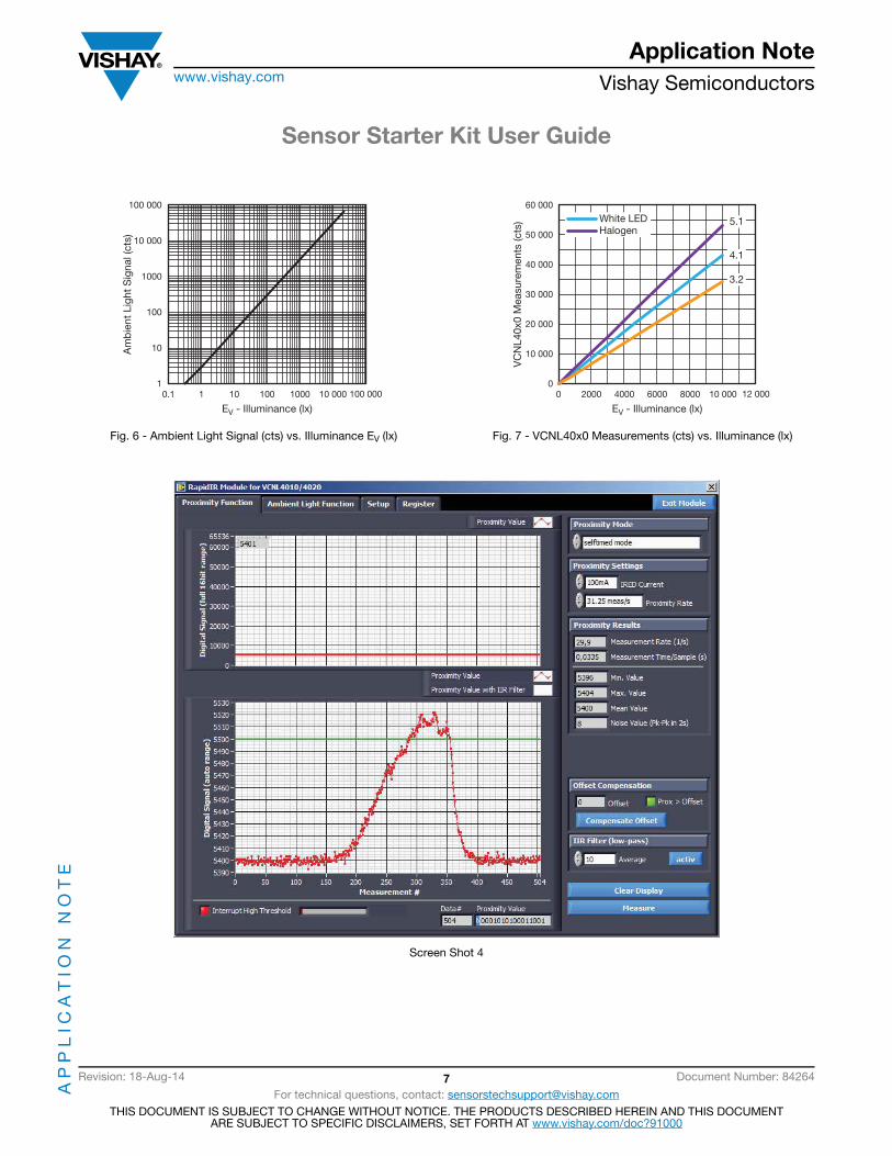
Displays the ambient light level in lux. It is calculated by dividing the number of counts by four. For example, there are 2400 counts which, when divided by four, results in 600 lx, see screen shot 3.
Figure of Merit
The ideal ambient light sensor will produce exactly the same output (counts) for the same brightness regardless of the source of light. In reality, silicon-based ambient light sensors will produce slightly different readings for halogen (2856 K CIE illuminant A), incandescent, fluorescent, and white LED sources. Figure 7 shows the average response for the VCNL40x0 ambient light sensors for all the above light sources and graphs the number of counts versus lux value for each light source. The halogen lamp shows a factor of 5.1 for digital counts versus lux, the fluorescent lamp shows a factor of 3.2 and white LEDs shows a factor of 4.1. The average response is a factor of 4 counts per lux. As shown in figure 6, a count of 1000 corresponds to 250 lx. This same count could be 200 lx for the halogen lamp or 310 lx for the fluorescent lamp. The overall tolerance for the VCNL40x0 ambient light sensor for different light sources is -22 % to +24 %.
The VCNL4010 and VCNL4020 have a sensitivity of 0.23 lux per count.
Periodic measurement (on demand)Single measurement (on demand)Selftimed mode
Measurement Rate(only available for seftimed mode)(
Measurement rate and time
Start / stop Measurement
Illuminance
Sensor Starter Kit User Guide
AP
PL
ICA
TIO
N N
OT
EApplication Note
www.vishay.com Vishay Semiconductors
Revision: 18-Aug-14 7 Document Number: 84264
For technical questions, contact: [email protected] DOCUMENT IS SUBJECT TO CHANGE WITHOUT NOTICE. THE PRODUCTS DESCRIBED HEREIN AND THIS DOCUMENT
ARE SUBJECT TO SPECIFIC DISCLAIMERS, SET FORTH AT www.vishay.com/doc?91000
Fig. 6 - Ambient Light Signal (cts) vs. Illuminance EV (lx) Fig. 7 - VCNL40x0 Measurements (cts) vs. Illuminance (lx)
Screen Shot 4
100 000
1
100
1000
10 000
10Am
bie
nt L
ight
Sig
nal (
cts)
EV - Illuminance (lx)0.1 1 10 100 1000 10 000 100 000
60 000
0
20 000
30 000
50 000
10 000
VC
NL4
0x0
Mea
sure
men
ts (c
ts)
EV - Illuminance (lx)0 2000 4000 6000 8000 10 000 12 000
40 000
White LEDHalogen
3.2
5.1
4.1

Sensor Starter Kit User Guide
AP
PL
ICA
TIO
N N
OT
EApplication Note
www.vishay.com Vishay Semiconductors
Revision: 18-Aug-14 8 Document Number: 84264
For technical questions, contact: [email protected] DOCUMENT IS SUBJECT TO CHANGE WITHOUT NOTICE. THE PRODUCTS DESCRIBED HEREIN AND THIS DOCUMENT
ARE SUBJECT TO SPECIFIC DISCLAIMERS, SET FORTH AT www.vishay.com/doc?91000
Interrupt
In order to set interrupt thresholds, it is necessary to determine the offset counts for the sensor. The offset count is application specific so it can only be determined by assembling the sensor with surrounding components with the cover or window above it. Offset counts are initially determined during development and may again be measured during assembly or final test of the end product. To determine the offset counts, the sensor’s proximity performance must be determined using the worst-case reflective object required to be detected at the desired distance it is to be detected. By adjusting the current of the infrared emitter, the range can be established. By adjusting the measurement speed, the response rate desired can be established. All these parameters together yield the total offset counts of the sensor without an object in range.
Example:
The sensor without any cover and close surrounding of other objects / components delivers about 2300 counts with an infrared emitter current of 100 mA. With some higher components close by and with a less transmissive cover this easily could rise up to 5000 or even 20 000 counts, depending on the distance and reflectivity of the cover used. As shown in screen shot 4, the offset counts are 5400. As an example, the application needs to detect an object at a distance of 5 cm. After some development trials, the sensor measures 5500 counts when the object is 5 cm distance and the forward current is 100 mA. For the application, the upper threshold will be set to 5500 counts, the green line in screen shot 4. When the counts exceed this threshold, in other words when an object is at 5 cm distance or less, an interrupt will be generated.
Screen Shot 5
Screen shot 5 shows the Setup page where the Interrupt Control variables are set or defined:
• Upper threshold val• Lower threshold value• Number of measurements above or below a threshold
needed to generate an interrupt• Enable interrupt threshold function• Threshold applies to proximity or ambient light
To avoid reacting to momentary object proximity, some applications will want to wait until several measurements are taken indicating an object is present or has been removed before generating an interrupt. The “Threshold hits needed” value is set to 4 in screen shot 5. The upper threshold is set to 5500 counts as discussed above. There is no lower threshold. The interrupt is enabled as indicated by the green arrow on the toggle button. Finally, the interrupt is for
Number of occurences to create an interrupt set to 4.The higher the value, the less likely small disturbances will impact performance
Interrupt threshold is enabled as indicated by the green arrow.When the threshold is exceeded, the flag for this will be enabled.
`High Threshold` register set to 5500.
Interrupt is for Proximity. If for ambient light, the green arrow would be lit

Sensor Starter Kit User Guide
AP
PL
ICA
TIO
N N
OT
EApplication Note
www.vishay.com Vishay Semiconductors
Revision: 18-Aug-14 9 Document Number: 84264
For technical questions, contact: [email protected] DOCUMENT IS SUBJECT TO CHANGE WITHOUT NOTICE. THE PRODUCTS DESCRIBED HEREIN AND THIS DOCUMENT
ARE SUBJECT TO SPECIFIC DISCLAIMERS, SET FORTH AT www.vishay.com/doc?91000
proximity because the green arrow is not illuminated. If it were for ambient light, the green arrow would be illuminated. Note that by clicking on the “show in graph” button under
each threshold value, the user will graphically be shown the threshold value in relation to the offset and current readings.
Screen Shot 6
Screen shot 6 demonstrates how a brief event, for example a quick swipe of a hand, exceeded the threshold but the number of consecutive measurements was less than 4 so an interrupt was not generated. Following this event, an object is within 5 cm for long enough for an interrupt to be generated. The “Interrupt High Thresold” indicator in the lower left corner is illuminated (red). Once an object
is detected, there are a number of possible actions an application can take. Continuous polling can be initiated to monitor the object’s proximity. Or, the current interrupt could be cleared, threshold values reprogrammed and the microcontroller freed to perform other activities or to sleep until an event occurs that generates a new interrrupt.
Upper threshold set to 5500 counts
Interrupt High Threshold is red because object was detected for at least four consecu�ve measurements
This event, for example a hand swipe, exceeded the threshold but the number of consecu�ve measurements was less than 4 so an interrupt was not ini�ated
Sensor Starter Kit User Guide
AP
PL
ICA
TIO
N N
OT
EApplication Note
www.vishay.com Vishay Semiconductors
Revision: 18-Aug-14 10 Document Number: 84264
For technical questions, contact: [email protected] DOCUMENT IS SUBJECT TO CHANGE WITHOUT NOTICE. THE PRODUCTS DESCRIBED HEREIN AND THIS DOCUMENT
ARE SUBJECT TO SPECIFIC DISCLAIMERS, SET FORTH AT www.vishay.com/doc?91000
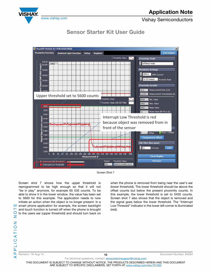
Screen Shot 7
Screen shot 7 shows how the upper threshold is reprogrammed to be high enough so that it will not “be in play” anymore, for example 65 535 counts. To be able to show it in the lower window, the value has been set to 5600 for this example. The application needs to now initiate an action when the object is no longer present. In a smart phone application for example, the screen backlight and touch function is turned off when the phone is brought to the users ear (upper threshold) and should turn back on
when the phone is removed from being near the user’s ear (lower threshold). The lower threshold should be above the offset counts but below the present proximity counts. In this example, the lower threshold is set to 5450 counts. Screen shot 7 also shows that the object is removed and the signal goes below the lower threshold. The “Interrupt Low Thresold” indicator in the lower left corner is illuminated (red).
Upper threshold set to 5600 counts
Interrupt Low Threshold is red because object was removed from in front of the sensor

Sensor Starter Kit User Guide
AP
PL
ICA
TIO
N N
OT
EApplication Note
www.vishay.com Vishay Semiconductors
Revision: 18-Aug-14 11 Document Number: 84264
For technical questions, contact: [email protected] DOCUMENT IS SUBJECT TO CHANGE WITHOUT NOTICE. THE PRODUCTS DESCRIBED HEREIN AND THIS DOCUMENT
ARE SUBJECT TO SPECIFIC DISCLAIMERS, SET FORTH AT www.vishay.com/doc?91000
Screen Shot 8
Screen shot 8 shows that the status bit indicator for low threshold, “value < low threshold,” has been illuminated (int_th_lo = 1).
Upper threshold`register reprogrammed to 5600.
Lower threshold`register set to 5450.
Measurement Speed- Sets the delay time between two consecutive measurements when in periodic
measurement mode. A delay time of “100” leads to about 10 measurements/sec. Choosing “1” leads to more than 200 measurements per second which is the fastest rate for this demo tool.

Sensor Starter Kit User Guide
AP
PL
ICA
TIO
N N
OT
EApplication Note
www.vishay.com Vishay Semiconductors
Revision: 18-Aug-14 12 Document Number: 84264
For technical questions, contact: [email protected] DOCUMENT IS SUBJECT TO CHANGE WITHOUT NOTICE. THE PRODUCTS DESCRIBED HEREIN AND THIS DOCUMENT
ARE SUBJECT TO SPECIFIC DISCLAIMERS, SET FORTH AT www.vishay.com/doc?91000
Screen Shot 9
External Emitter Settings
In screen shot 9 the Setup screen for the VCNL4010 and VCNL4020 is shown. For the VCNL4020X01 and also for the VCNL3020 - which comes without the ambient light sensor - the same demo software is used. Under the red Sensor Board section, the default “internal emitter” indicator is illuminated. Users have the option of selecting the use of an external emitter or using both internal and external emitter. The supply voltage for the external emitter is called VIR and connected via the USB controller board to a 3.3 V power supply, see figure 8 and 9. It can be connected to a separate power supply. If internal and external infrared emitters will be driven in series, they need to be connected to a higher voltage.
The blue Proximity Modulator Adjustment section of the Setup screen shows default values for the use of the integrated infrared emitter. When using external emitters or a combination of an internal and external emitter, the modulation delay time, modulation dead time, and proximity frequency may need to be adjusted. Please refer to the VCNL4010, VCNL4020, or VCNL3020 Application Notes for further details.
The green Proximity Measurement On Demand section of the Setup screen allows users to adjust the delay between two consecutive measurements. Any value between 0 and 10 000 can be entered in the field. A value of 0 results in 1 ms between measurements (200 measurement per second) while a value of 10 000 results in about 10 seconds between measurements.

Sensor Starter Kit User Guide
AP
PL
ICA
TIO
N N
OT
EApplication Note
www.vishay.com Vishay Semiconductors
Revision: 18-Aug-14 13 Document Number: 84264
For technical questions, contact: [email protected] DOCUMENT IS SUBJECT TO CHANGE WITHOUT NOTICE. THE PRODUCTS DESCRIBED HEREIN AND THIS DOCUMENT
ARE SUBJECT TO SPECIFIC DISCLAIMERS, SET FORTH AT www.vishay.com/doc?91000
SCHEMATIC
Fig. 8 - Circuit Diagram of VCNL4020 Sensor Board
IRE
GND
INT
IRI
SCL
SDA
3V3
VIRA
C
optional
+3.3 V
+3.3 V
+3.3 V
+3.3 V
VIR VIR
VIR (2.5 V to 3.3 V) (1)
J4NC
1
J13+5 V
1
R2
4.7K
TP7
1D1
VLMS1300-GS08
TP4
1
R6Jumper 0R
R34.7K
J8NC
1
TP101J12
NC1
J5PA0
1
R1
300R
D2VSMF2890GX01
R5Jumper 0R
J1SDA
1
TP6
1
J11VCC
1
J2GND
1
TP3
1
Q2Si2302
J16NC
1 TP1
1
J6VCC
1
J10NC
1
U224LC64B
VC
C4
WP5
SCL1
GN
D2
SDA3
Q1Si2301
TP8
1
J3SCL
1
J15GND
1
J9VIN+
1
TP5
1
TP2
1
R44.7K
J14NC
1
J7PA2
1
C1
470 nF
AmbiPD
ProxiPD
IRED
SDA
SCL
Anode
Cathode
VR
VDD GNDGND
VCNL4020 - IC
INT
U1
1
10
24
985
11
3
TP91
Edge connector 16 pos.
Pinning for VISHAY USB Stick
When using the VCNL4020 sensor board without VISHAY USB stick,an additional pullup resistors (2.4 to 10K) on SDA and SCL is necessary
Note(1) VIR may be set > 3.3 V (< 5 V), however then Q1 will no longer short circuit the external emitter D2
IREIRI IRED operating
L or open H both IREDsH L or open forbiddenH H only external IRED
L or open L or open only internal IRED

Sensor Starter Kit User Guide
AP
PL
ICA
TIO
N N
OT
EApplication Note
www.vishay.com Vishay Semiconductors
Revision: 18-Aug-14 14 Document Number: 84264
For technical questions, contact: [email protected] DOCUMENT IS SUBJECT TO CHANGE WITHOUT NOTICE. THE PRODUCTS DESCRIBED HEREIN AND THIS DOCUMENT
ARE SUBJECT TO SPECIFIC DISCLAIMERS, SET FORTH AT www.vishay.com/doc?91000
Fig. 9 - Circuit Diagram of VCNL4010 Sensor Board
The switching information (IRI and IRE) is delivered from the USB controller and the specification given above.
ADDITIONAL REMARKS1. The demo software behind this Sensor Starter Kit is LabVIEW based. Due to licensing issues we cannot provide the LabVIEW
source code.2. The controller within the USB dongle is a Cypress CY7C68013.3. The nominal I2C-bus speed is about 100 kHz.4. The required pull-up resistors at the SDA and SCL lines are within the dongle and connected to 3.3 V.5. A small regulator provides all sensor boards with 3.3 V. Eventually the needed 2.5 V are created on the corresponding boards.6. For additional handling of analog voltages, an A/D converter (MCP3421) is included within this dongle. Its address is “A0.”7. These added rows of “test pins” shown in figures 3 and 5) allow a connection to your own application. Do not forget to add the
needed SDA / SCL pull-up resistors in this case. For all VCNL40x0 and VCNL3020 sensor boards it should also be noted, that the anode side of the available external IRED needs to be connected to a supply voltage between 2.5 V and 5 V. This is done within the USB dongle.
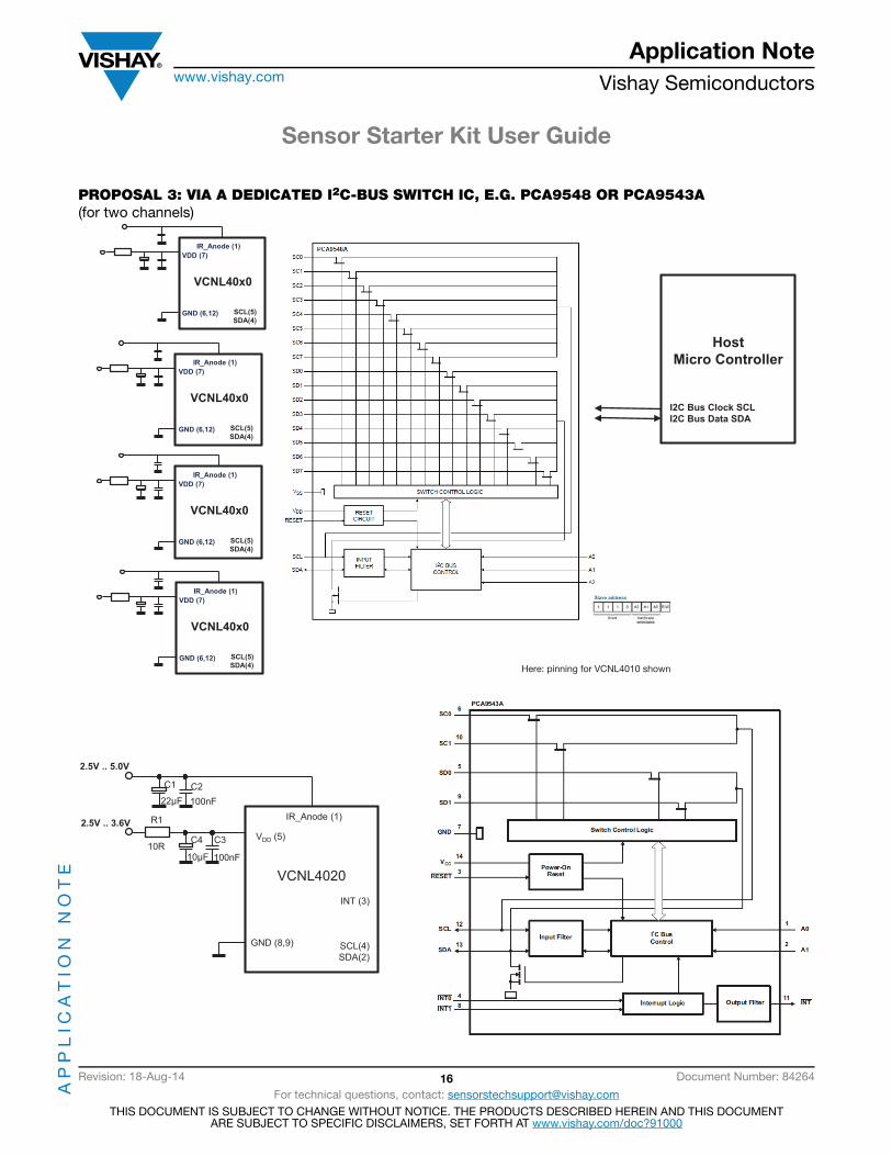
8. All VCNLs come with one and the same I2C-bus address: 26h for write and 27h for read. If more than one VCNL is used within an application, a switch for the I2C-bus lines is needed. Please see some proposals on next pages.
For using VCNL4010 sensor board without VISHAY USB stickadditional pullup resistors (2.4 to 10K) on SDA and SCL necessary
IREIRI IRED operating
L or open H both IREDsH L or open forbiddenH H only external IRED
L or open L or open only internal IRED
IRE
GND
INT
IRI
SCL
SDA
3V3
5 VA
C
optional
+3.3 V
+3.3 V
+3.3 V
+3.3 V
VIR VIR
VIR (2.5 V to 5 V)
J4NC
1
J13NC
1
R2
4.7K
TP7
1
D1
VLMS11Q1R2
TP4
1
R6Jumper 0R
R34.7K
J8NC
1
TP101J12
NC1
J5PA0
1
R1
300R
D2VSMF2890GX01
R5Jumper 0R
J1SDA
1
TP6
1
J11VCC
1
J2GND
1
TP3
1
Q2Si2302
J16NC
1 TP1
1
J6NC
1
J10NC
1
AmbiPD
ProxiPD
IRED
SDA
SCL
Anode
Cathode
VR
GNDVDD
VCNL4010 - IC
INTGND
U1
1
2
45
127
3
613 U224LC64B
VC
C4
WP5
SCL1
GN
D2
SDA3
Q1Si2301
TP8
1
J3SCL
1
J15GND
1
J9VIN+
1
TP5
1
TP2
1
R44.7K
J14NC
1
J7PA2
1
C1
470 nF
TP91
Edge connector 16 pos.
Pinning for VISHAY USB Stick

Sensor Starter Kit User Guide
AP
PL
ICA
TIO
N N
OT
EApplication Note
www.vishay.com Vishay Semiconductors
Revision: 18-Aug-14 15 Document Number: 84264
For technical questions, contact: [email protected] DOCUMENT IS SUBJECT TO CHANGE WITHOUT NOTICE. THE PRODUCTS DESCRIBED HEREIN AND THIS DOCUMENT
ARE SUBJECT TO SPECIFIC DISCLAIMERS, SET FORTH AT www.vishay.com/doc?91000
PROPOSAL 1: SWITCHED VDD
PROPOSAL 2: SWITCHED SDA
HostMicro Controller
I2C Bus Clock SCLI2C Bus Data SDA
VCNL40x0
SCL(5)SDA(4)GND (6,12)
VDD (7)
IR_Anode (1)
VCNL40x0
SCL(5)SDA(4)GND (6,12)
VDD (7)
IR_Anode (1)
GPIO
Here: pinning for VCNL4010 shown
HostMicro Controller
I2C Bus Clock SCLI2C Bus Data SDA
VCNL40x0
SCL(5)SDA(4)GND (6,12)
VDD (7)
IR_Anode (1)
VCNL40x0
SCL(5)SDA(4)GND (6,12)
VDD (7)
IR_Anode (1)
GPIOswitching the SDA line,
e.g. With single bus switch as74CBTLV1G125
Here: pinning for VCNL4010 shown
Sensor Starter Kit User Guide
AP
PL
ICA
TIO
N N
OT
EApplication Note
www.vishay.com Vishay Semiconductors
Revision: 18-Aug-14 16 Document Number: 84264
For technical questions, contact: [email protected] DOCUMENT IS SUBJECT TO CHANGE WITHOUT NOTICE. THE PRODUCTS DESCRIBED HEREIN AND THIS DOCUMENT
ARE SUBJECT TO SPECIFIC DISCLAIMERS, SET FORTH AT www.vishay.com/doc?91000
PROPOSAL 3: VIA A DEDICATED I2C-BUS SWITCH IC, E.G. PCA9548 OR PCA9543A (for two channels)
HostMicro Controller
I2C Bus Clock SCLI2C Bus Data SDA
SCL(5)SDA(4)
GND (6,12)
VDD (7)IR_Anode (1)
VCNL40x0
SCL(5)SDA(4)
GND (6,12)
VDD (7)IR_Anode (1)
VCNL40x0
SCL(5)SDA(4)
GND (6,12)
VDD (7)IR_Anode (1)
VCNL40x0
SCL(5)SDA(4)
GND (6,12)
VDD (7)IR_Anode (1)
VCNL40x0
Here: pinning for VCNL4010 shown
VCNL4020
INT (3)
SCL(4)SDA(2)
GND (8,9)
VDD (5)
IR_Anode (1)
C1 C2
C3C4
R1
100nF
100nF10µF
22µF
10R
2.5V .. 3.6V
2.5V .. 5.0V

Sensor Starter Kit User Guide
AP
PL
ICA
TIO
N N
OT
EApplication Note
www.vishay.com Vishay Semiconductors
Revision: 18-Aug-14 17 Document Number: 84264
For technical questions, contact: [email protected] DOCUMENT IS SUBJECT TO CHANGE WITHOUT NOTICE. THE PRODUCTS DESCRIBED HEREIN AND THIS DOCUMENT
ARE SUBJECT TO SPECIFIC DISCLAIMERS, SET FORTH AT www.vishay.com/doc?91000
A web page shows all available sensor boards that can be used with the Sensor Starter Kit: