Sensor Network for Landslide Monitoring With Laser Ranging System Avoiding Rainfall Influence on...
12
Kohei Arai International Journal of Applied Sciences (IJAS), Volume (3) : Issue (1) : 2012 1 Sensor Network for Landslide Monitoring With Laser Ranging System Avoiding Rainfall Influence on Laser Ranging by Means of Time Diversity and Satellite Imagery Data Based Landslide Disaster Relief Kohei Arai [email protected] Information Science Department Saga University Saga City, 840-8502, Japan Abstract Sensor network for landslide monitoring with laser ranging system is developed together with landslide disaster relief with remote sensing satellite imagery data. Time diversity is utilized for rainfall influence avoidance in the distance measurements between laser ranging equipment and targets. Also automatic tie point extraction method is proposed. Experimental results show that (1) the proposed time diversity of the laser ranging measurement does work for avoidance from rainfall influence; (2) the proposed automatic control point extraction method does work for tie point matching together with change detection for landslide disaster relief. Keywords: landslide, Control Point Detection, Change Detection, Remote Sensing Satellite Imagery Data, Time Diversity. 1. INTRODUCTION Landslide is one of severe disaster. In order to monitor landslides, several methods have been proposed so far. One of the conventional land slide monitoring systems is to measure the resistance of the wire which is set at potential landslide steeply slopes. Although it is simple and cheap system, measurement accuracy is not so good in terms of the distance between two ends of the wire which depends on resistance. Therefore, it cannot be used for making caution for evacuation from the potential landslide area. Other wide variety of commercial off-the-shelf electronic and/or mechanical geotechnical and hydrologic sensors exist [1],[2]. Meanwhile, satellite remote sensing imagery data is used for disaster relief due to landslide. It cannot be used for landslide warning system. There are so many previously proposed methods for detection of landslide areas such as differentiation with edge enhancing filters [3], texture feature extraction [4], vegetation index utilized land cover change detection method [5], 3D stereo pair of images utilized change detection method [6], etc. The landslide monitoring method proposed here is to utilize laser ranging system as a sensor network. The distance between the laser ranging instrument and the target which is set at potential landslide areas can be measured with the laser ranging system. If the measured distance is not changed then it is understood any landslide is not happened. The initial movement of typical landslide is around a few millimeters. Therefore, it is effective is the laser ranging system can measure a few millimeters distance changes. Measured distance data can be transmitted from the site of where the laser ranging system is equipped to Internet terminals in the disaster mitigation center. After that, caution for evacuation can be provided from the center through TV broadcast stations with data broadcasting. Conventional method for landslide monitoring uses wire current or voltage difference between two ends of the wire. Such method is not good enough for detection of initial movement of landslide. Movement accuracy of conventional methods is around a couple of cm while that of the proposed method is a couple of mm. Therefore, the proposed method is useful to detect initial movement of landslide even under
-
Upload
waqas-tariq -
Category
Education
-
view
188 -
download
0
Transcript of Sensor Network for Landslide Monitoring With Laser Ranging System Avoiding Rainfall Influence on...

Kohei Arai
International Journal of Applied Sciences (IJAS), Volume (3) : Issue (1) : 2012 1
Sensor Network for Landslide Monitoring With Laser Ranging System Avoiding Rainfall Influence on Laser Ranging by Means
of Time Diversity and Satellite Imagery Data Based Landslide Disaster Relief
Kohei Arai [email protected] Information Science Department Saga University Saga City, 840-8502, Japan
Abstract
Sensor network for landslide monitoring with laser ranging system is developed together with landslide disaster relief with remote sensing satellite imagery data. Time diversity is utilized for rainfall influence avoidance in the distance measurements between laser ranging equipment and targets. Also automatic tie point extraction method is proposed. Experimental results show that (1) the proposed time diversity of the laser ranging measurement does work for avoidance from rainfall influence; (2) the proposed automatic control point extraction method does work for tie point matching together with change detection for landslide disaster relief.
Keywords: landslide, Control Point Detection, Change Detection, Remote Sensing Satellite Imagery Data, Time Diversity.
1. INTRODUCTION Landslide is one of severe disaster. In order to monitor landslides, several methods have been proposed so far. One of the conventional land slide monitoring systems is to measure the resistance of the wire which is set at potential landslide steeply slopes. Although it is simple and cheap system, measurement accuracy is not so good in terms of the distance between two ends of the wire which depends on resistance. Therefore, it cannot be used for making caution for evacuation from the potential landslide area. Other wide variety of commercial off-the-shelf electronic and/or mechanical geotechnical and hydrologic sensors exist [1],[2]. Meanwhile, satellite remote sensing imagery data is used for disaster relief due to landslide. It cannot be used for landslide warning system. There are so many previously proposed methods for detection of landslide areas such as differentiation with edge enhancing filters [3], texture feature extraction [4], vegetation index utilized land cover change detection method [5], 3D stereo pair of images utilized change detection method [6], etc. The landslide monitoring method proposed here is to utilize laser ranging system as a sensor network. The distance between the laser ranging instrument and the target which is set at potential landslide areas can be measured with the laser ranging system. If the measured distance is not changed then it is understood any landslide is not happened. The initial movement of typical landslide is around a few millimeters. Therefore, it is effective is the laser ranging system can measure a few millimeters distance changes. Measured distance data can be transmitted from the site of where the laser ranging system is equipped to Internet terminals in the disaster mitigation center. After that, caution for evacuation can be provided from the center through TV broadcast stations with data broadcasting. Conventional method for landslide monitoring uses wire current or voltage difference between two ends of the wire. Such method is not good enough for detection of initial movement of landslide. Movement accuracy of conventional methods is around a couple of cm while that of the proposed method is a couple of mm. Therefore, the proposed method is useful to detect initial movement of landslide even under
Kohei Arai
International Journal of Applied Sciences (IJAS), Volume (3) : Issue (1) : 2012 2
a heavy rain condition. To avoid the influence scattering of laser light due to raindrops, time diversity method is proposed. On the other hand, landslide disaster relief can be done with satellite remote sensing data. In order to detect landslide, changes between two satellite remote sensing imagery data which are acquired on the different day have to be detected. Before that two satellite imagery data have to be registered with tie point matching. In this paper, automatic tie point or control point extraction method is also proposed. Thus geometric correction can be applied to two remote sensing satellite imagery data. Tie points have to be extracted from two images. There are some conventional automatic tie point extraction methods based on feature extraction [7],[8],[9]. The conventional tie point uses line and circle features. The proposed method is simple and accurate because it is just find "L" and "X" shaped line features extracted with Hough transformation is used. The corners and cross points are easy to extract and accurate enough for tie point matching. The following section describes the proposed whole system for landslide monitoring followed by landslide monitoring system with laser ranging system. After that landslide disaster relief method with satellite remote sensing imagery data is proposed together with some experimental results.
2. PROPOSED SYSTEM
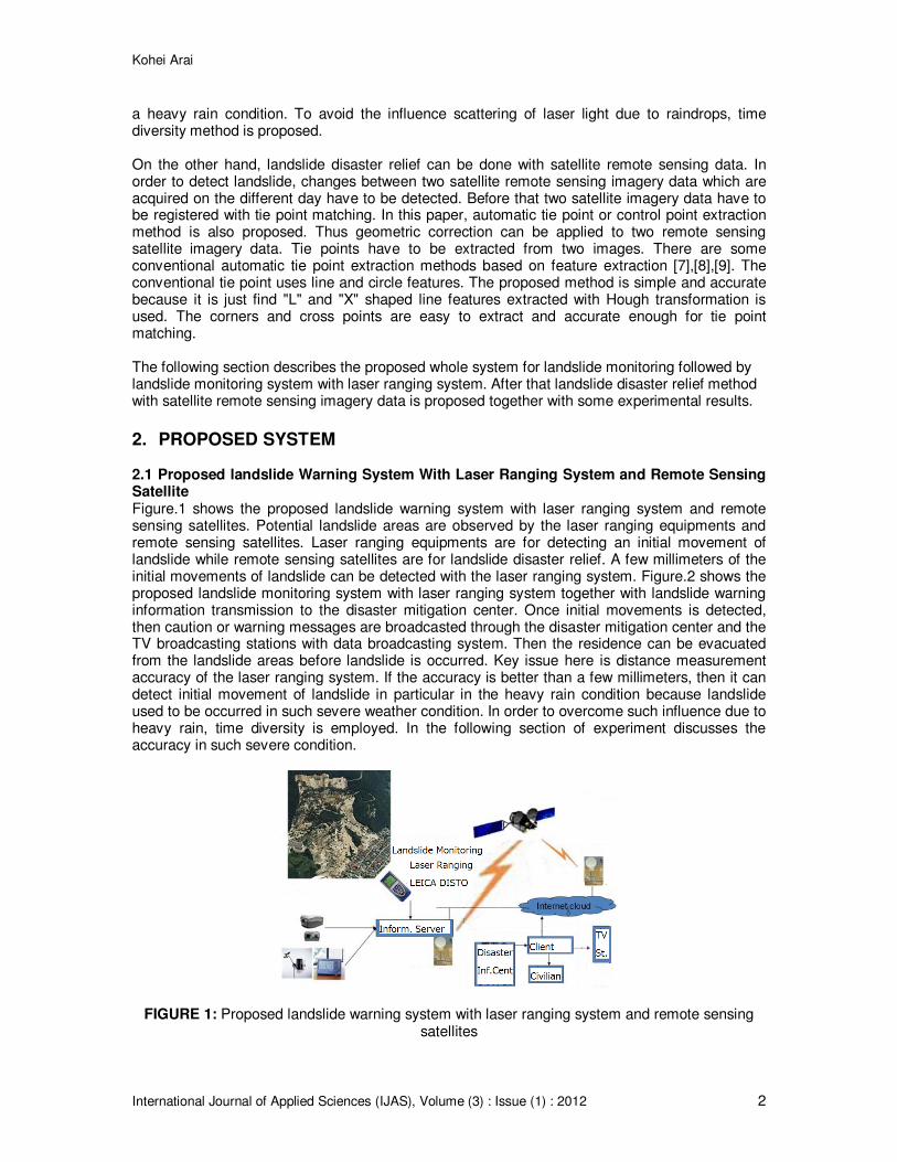
2.1 Proposed landslide Warning System With Laser Ranging System and Remote Sensing Satellite Figure.1 shows the proposed landslide warning system with laser ranging system and remote sensing satellites. Potential landslide areas are observed by the laser ranging equipments and remote sensing satellites. Laser ranging equipments are for detecting an initial movement of landslide while remote sensing satellites are for landslide disaster relief. A few millimeters of the initial movements of landslide can be detected with the laser ranging system. Figure.2 shows the proposed landslide monitoring system with laser ranging system together with landslide warning information transmission to the disaster mitigation center. Once initial movements is detected, then caution or warning messages are broadcasted through the disaster mitigation center and the TV broadcasting stations with data broadcasting system. Then the residence can be evacuated from the landslide areas before landslide is occurred. Key issue here is distance measurement accuracy of the laser ranging system. If the accuracy is better than a few millimeters, then it can detect initial movement of landslide in particular in the heavy rain condition because landslide used to be occurred in such severe weather condition. In order to overcome such influence due to heavy rain, time diversity is employed. In the following section of experiment discusses the accuracy in such severe condition.
FIGURE 1: Proposed landslide warning system with laser ranging system and remote sensing satellites

Kohei Arai
International Journal of Applied Sciences (IJAS), Volume (3) : Issue (1) : 2012 3
FIGURE 2: Proposed landslide monitoring system with laser ranging system together with landslide warning information transmission to the disaster mitigation center.
2.2 Proposed landslide Disaster Relief With Remote Sensing Satellite Imagery Data Figure.3 shows examples of the remote sensing imagery data which are acquired on the different days, (a) before and (b) after landslide occurrence. The potential landslide areas are known. Therefore, when remote sensing satellite visits potential landslide areas, it can be acquire imagery data. Once landslide occurs, then, remote sensing satellites acquire the imagery data immediately after the landslide. In order to detect change between two satellite imagery data which are acquired before and after landslide occurrence, two images have to be matched. Before making image matching, tie points in the images have to be extracted. Figure.4 shows the process flow of the automatic tie point extractions. Firstly, potential landslide portion of images are extracted from two satellite images. Then image intensity is inverted to enhance edge information. After that, contrast of the images is enhanced followed by binarization. Then linear features are extracted with Hough transformation. After that, longest line feature is selected. Then cross line with the detected longest line is detected. Thus “L” or “X” character type of tie point is extracted. By using extracted tie points, two satellite images are matched. Then difference between matched two images which corresponds to changes between satellite images which are acquired before and after landslide occurrence can be detected. Thus location and size of landslide can be detected and estimated.
(a) Example of satellite image which is acquired after landslide occurrence.
(b) Example of satellite image which is acquired before landslide occurrence.

Kohei Arai
International Journal of Applied Sciences (IJAS), Volume (3) : Issue (1) : 2012 4
FIGURE 3: Examples of satellite imagery data which are acquired before and after landslide occurrence.
FIGURE 4: Process flows of automatic tie point extractions.
3 EXPERIMENTS
3.1 Proposed landslide Monitoring System Potential landslide areas are investigated and are on the web site
1. From the site, for instance,
potential areas are retrieved with their severe degrees. Depending on the degree of severances, three test sites in the Saga prefecture Japan are selected. Figure.5 (a), (b), and (c) shows test sites, (1) Yamashiro town of the Imari city, (2) Ohchicho of the Karastu city, and (3) Fujicho of the Saga city.
1 http://disapotal.gsi.go.jp/

Kohei Arai
International Journal of Applied Sciences (IJAS), Volume (3) : Issue (1) : 2012 5
(a) Yamashiro town of the Imari city (b) Ohchicho of the Karastu city
(c) Fujicho of the Saga city FIGURE 5: Locations of the potential landslide areas (Red circles) ((c)Google)
Figure.6 shows the outlook of the equipments including laser ranging system installed at the potential landslide areas. Configuration of the equipments is illustrated in Figure.7. There two types of the equipments, Target#1 and 2. In the Target #1, there is not only laser ranging equipment but also meteorological data acquisition system and camera system for acquire sight scene. Target #2 is for experimental equipment which allows measurements of the critical enforcement when landslide occurs. In the experiments with Target #2, simulated rainfall of water is supplied from the top of the Target #2. Figure.8 shows network configuration of the proposed landslide monitoring system. Acquired laser ranging data and camera data as well as meteorological data area transmitted from the sites to Internet terminal with Auto-Pilot. Under Internet, users may access to the data from the web server through router.
(a) Yamashiro town of the Imari city (b) Ohchicho of the Karastu city

Kohei Arai
International Journal of Applied Sciences (IJAS), Volume (3) : Issue (1) : 2012 6
(c) Fujicho of the Saga city FIGURE 6: The Equipments installed at the potential landslide areas
FIGURE 7: Configurations for the proposed landslide monitoring system with laser ranging equipment implemented at the test sites and experimental configuration which simulates landslide
in heavy rainfall conditions.

Kohei Arai
International Journal of Applied Sciences (IJAS), Volume (3) : Issue (1) : 2012 7
FIGURE 8: Network configuration of the proposed landslide monitoring system.
3.2 Experiments of the Landslide Monitoring With Laser Ranging Equipments Figure.9 shows configuration of the experiments of the landslide monitoring with laser ranging equipments. Target with concrete is put on thick layered sand at the middle location of the slope. From the top of the slope, simulated rainfall of water is put into the sands layer between the slope and Target #2. Table 1 shows the major specification of laser ranging equipment of Leica Disto A6. It can measure distance between the laser ranging equipment and the target with ±1.5mm of accuracy for distance between both ranges from 0.05 to 80m. Laser wavelength is 635nm. It is pulsed laser with interval rages from 1 (ms) to 1 (sec). The most appropriate time interval has to be determined through a trial and error. Also the most appropriate time interval for time diversity has to be determined through experiments.
TABLE 1: Specification of laser ranging equipment of Leica Disto A6
Range 0.05-80m
accuracy ±1.5mm
Time 1ms to 1sec
FIGURE 9: Experiment configurations for simulated landslide

Kohei Arai
International Journal of Applied Sciences (IJAS), Volume (3) : Issue (1) : 2012 8
FIGURE 10: Photo of the simulated landslide Figure.10 shows photo of the simulated landslide. The experiments are conducted with several slope angles. Laser raging equipment is set-up at the slope end with perpendicular to the target depending on the slope angle. As shown in Figure.10, simulated rainfall of water is put into the sand layer. The static friction coefficient of the sand is 0.7. Target #2 weighs about 20 Kg. Experimental conditions are 41.672 degrees of the slope angle, 2.5mm/h of rainfall. Thus the vertical enforcement, F=mN=14Kg. Target #2 with concrete is touched with the sand layer with 35cm by 35cm of area. For the aforementioned condition, 15 second after start to put the water into the sand layer, Target #2 is moved down to the end of slope. Therefore, it may conclude that the slope is destroyed, landslide occurs with 25mm/h of rainfall within 2 second. It totally depends on the static friction coefficient of the soil, slope angle, weight of the surface layer of the land, and rainfall rate. 3.3 Performance of the Laser Ranging Equipments and Time Diversity Effect Leica Disto A6
2 of laser ranging equipment is tested with the different color of target and with the
different set angles, 0, 20, and 40 degrees. Experimental configuration is illustrated in Figure.11. Also experimental results are shown in Table 2 and Figure.12. As shown in Table 2 and Figure.12, no error is dominant frequency obviously. Also brown colored target is much accurate rather than white target in terms of distance measurement accuracy. In these cases, most appropriate time interval is 100ms. Under a heavy rainfall condition, laser light is scattered with raindrops. Therefore, returned laser echo from the raindrops reaches to the laser ranging equipment much faster than that from the target. If measurement interval is set to 1 second, then 10 measured distances can be used to determine the distance between laser ranging equipment and target. Thus the maximum measured distance can be used as the most appropriate distance between both. This is called time diversity concept. Table 3 shows the effect of the time diversity. The mean accuracy and standard deviation of measured distance with and without time diversity is shown in Table 3. Approximately 33% of improvement of mean accuracy is confirmed for time diversity effect.
2 http://www.leicadisto.co.uk/products/disto_a6.html

Kohei Arai
International Journal of Applied Sciences (IJAS), Volume (3) : Issue (1) : 2012 9
FIGURE 11: Experimental configuration for performance evaluation of laser ranging equipment of Leica Disto A6.
FIGURE 12: Probability density function of distance measurement error.
TABLE 2: Frequency of the measured distance error in unit of mm
Target Set Angle Frequency of the measured distance error in unit of mm
Color (degree) -3 -2 -1 0 1 2 3
Brown 0 0 0 0 59 0 0 0
20 0 0 8 45 6 0 0
40 0 0 14 43 1 1 0
White 0 0 0 9 27 14 9 0
20 0 1 5 26 13 14 0
40 0 1 6 27 18 5 2
TABLE 3: Mean and standard deviation (Std.Dev.) of distance measurement errors with/without
time diversity (TD)
without TD with TD
Mean 7.9 5.9
Std.Dev. 0.00636 0.00487
3.4 Automatic tie point extraction performance Using Hough transformation, line features are extracted from the binarized image of remote sensing satellite imagery data as shown in Figure.13 (a). In the extracted line features, the longest line is selected. Then L or X character type of feature with the selected longest line feature is detected as shown in Figure.13 (b).

Kohei Arai
International Journal of Applied Sciences (IJAS), Volume (3) : Issue (1) : 2012 10
Thus image matching can be done using a plenty of tie points detected from the four corners of the image. Also it makes image matching by using manually extracted tie points through human perception as shown in Figure.14 (a). In this case, user appoints tie points by pixel by pixel basis in the image of Figure.14 (a). Then the difference between two satellite images which are acquired on before and after landslide occurrence is derived as shown in Figure.14 (b). After all, changes during land slide can be extracted as shown in Figure.14 (c). Red colored portions of Figure.14 (c) is actual landslide area.
(a) Extracted line features (b) Detected L or X character type of feature
FIGURE 13: Tie point detection
(a)Screen shot image for manual extraction (b)Difference between two satellite images of tie points. which are acquired on before and after
landslide occur

Kohei Arai
International Journal of Applied Sciences (IJAS), Volume (3) : Issue (1) : 2012 11
(c)Detected landslide areas (Red colored portion) FIGURE 14: Manual tie point extraction, detected difference between two satellite images and
extracted landslide areas with the proposed method.
4. CONCLUSION It is found that the proposed landslide monitoring system with laser ranging equipment and the proposed landslide disaster relief with remote sensing satellite imagery data does work so well. In particular, laser ranging equipment allows around 2-3mm of distance measurement accuracy for the distance between laser ranging equipment and target of 20m. Also around 30% improvement of time diversity effect is confirmed in comparison to the conventional method without time diversity. This landslide monitoring with laser ranging equipment of sensor network is original system of this paper. Landslide usually occurs under a heavy rainfall condition. Heavy rain affects to laser ranging through scattering of laser light due to raindrops. Therefore, some countermeasure has to be taken into account. Time diversity (extract the longest distance measurement data during a relatively long period of measuring time) is adopted. As shown in Fig.12 and Table 2 and 3, 2-3mm of distance measurement accuracy is achieved by the proposed method. 2-3mm of accuracy is good enough for initial stage of landslide detection. Conventional method for landslide monitoring is based on wire current and/or voltage difference between two ends of the wire. The accuracy is around a couple of cm. Therefore, it is not useful to detect initial movement of the land before landslide. On the other hand, automatic tie point extractions and change detection between before and after
landslide occurs satellite images also work so well. From extracted image portion, tie points which are appropriate for image matching which are acquired on the different days, before and after landslide occur can be extracted. Then change detection, cross comparison between two images
can be done perfectly. Land cover change implies landslide occur. Therefore, landslide is relieved with two satellite images. Hazard map created by the ministry of land, infrastructure, transportation and tourism shows potential landslide areas in Japan. Therefore, satellite imagery
database for the potential areas can be created. Only thing we have to do is to detect changes between before (in the satellite imagery database) and after (currently acquired satellite image) landslide occurs. Two images have to be matched for change detections. By using tie points between two images based on the proposed method of tie points extraction, a good enough
matching accuracy (a sub-pixel order) can be achieved. Tie points which are situated at the corner of "L" character type or crossing points of "X" character type can be detected with line features extracted based on Hough transformation are original feature of this paper. The
proposed method is validated with 10m spatial resolution of ALOS/AVNIR-2 imagery data. As shown in Fig.14 (c), landslide areas are detected perfectly. It is also confirmed that the proposed method is superior to the conventional method for tie point extraction which is based on feature
extraction methods.

Kohei Arai
International Journal of Applied Sciences (IJAS), Volume (3) : Issue (1) : 2012 12
5. ACKNOWLEDGEMENT This research is founded by the ministry of education, culture, sport, science and technology of Japan as a part of “Ultra small earth observation satellite of Kyushu, so called QSAT-EOS development”. In this connection, author would like to thank to all the staff of the ministry. Also author would like to thank to Map Station Co. Ltd. for their experimental effort to construct landslide monitoring system with laser ranging equipment.
6. REFERENCES [1] Dunnicliff, J. 1993. Geotechnical Instrumentation for Monitoring Field Performance. New
York: John Wiley & Sons
[2] Mikkelsen, P.E. 1996. Field instrumentation. In A.K. Turner & R.L. Schuster (eds), Landslides: Investigation and Mitigation, Special Report 247: 278–316. Washington, DC: National Academy Press.
[3] Eyers, R., Moore, J. McM., Hervas, J. and Lui, J. G., 1995. Landslide mapping using digital
imagery: a case history from south east Spain”. Proc. 31st Annual Conf. on Geohazards and Engineering Geology, 379 – 388. 1995, Coventry, UK
[4] Wang, L. and He, D. C. “A new statistical approach for texture analysis”. Photogrammetric
Engineering and Remote Sensing, 56 (1), 61 – 66. 1990. [5] Zhang, Z.; Gong, H.; Zhao, W.; Zhang, Y. 2005. AppLeication of remote sensing to study of
landslides. IEEE, 1546-1549.
[6] Rosin, P.L. and Hervás, J. (2005). Remote sensing image thresholding methods to determining landslide activity. International Journal of Remote Sensing, 26, 6, 1075-1092.
[7] Forstner W. and E. Gulch, 1987, A fast operator for detection and precise location of distinct
points, corners and centers of circular features, ISPRS Intercom. Workshop, Interlaken, 281-304.
[8] Schmidt, R., Brand, R., 2003. Automatic determination of tie points for HRSC on Mars
Express, ISPRS Workshop High Resolution Mapping from Space 2003, October 6-8, 2003, Hannover.
[9] Förstner, W., 1986. A feature based correspondence algorithm for image matching,
IntArchPhRS, (26) 3/3, pp. 150-166.