
Sensor MPE Dimming System User’s Manualalpsweb.com/admin/resources/manuals/mpe-user-manu… ·...
20
Sensor MPE Dimming System User’s Manual
-
Upload
truongdiep -
Category
Documents
-
view
219 -
download
1
Transcript of Sensor MPE Dimming System User’s Manualalpsweb.com/admin/resources/manuals/mpe-user-manu… ·...

Sensor MPE Dimming System
User’s Manual

2 Electronic Theatre Controls, Inc.
Sensor MPE Dimming User Manual 3
Contents
Introduction
.............................................................................................. 5How to use this manual ........................................................................... 5Sensor MPE overview.............................................................................. 6
Operation
................................................................................................... 7Basic operation......................................................................................... 7Using the Multi-Protocol Electronics (MPE) module ................................ 7
Maintenance
............................................................................................. 9Cleaning dimmer rack air filters................................................................ 9Vacuuming dimmer racks....................................................................... 10
Service
....................................................................................................... 11Contacting ETC about equipment problems .......................................... 11Changing Installation Rack modules ...................................................... 11Using dimmer module circuit breakers .................................................. 11Internal MPE configuration settings....................................................... 13Test switch operation............................................................................. 14Changing MPE phase fuses ................................................................... 14Troubleshooting ..................................................................................... 15
Make a preliminary examination of your system................................ 15Using the MPE for direct control and testing ..................................... 15Check system status with the MPE front panel display..................... 17Running the Show Beacon Errors tests ............................................. 18
Specifications
......................................................................................... 19

4 Electronic Theatre Controls, Inc.

Sensor MPE Dimming User Manual 5
Introduction
Welcome to the User Manual for the Sensor MPE dimming system. This manual contains operating instructions for Sensor MPE dimming systems. There are two Sensor MPE installation racks, the six slot SR6 and the twelve slot SR12.
How to use this manual
Manual organization
This manual has separate sections to tell you how to use, maintain and troubleshoot your Sensor MPE dimming system:
▼
Operation
on page 7 describes system operation and normal operating indications
▼
Maintenance
on page 9 describes routine system maintenance
▼
Service
on page 11 tells you how to perform repairs and replace defective components
▼
Troubleshooting
on page 15 tells you how to correct problems you might experience with your system and how to contact ETC to get more advanced technical assistance.
▼
Specifications
on page 19 describes basic system specs
Warnings and notice conventions
These symbols alert you to danger or important information:
Warning!
Warns you when electricity may cause injury
Warning!
Warns you when there is a possibility of other types of injury
Caution
Alerts you to important information relating to equipment performance or reliability
Contacting ETC
For questions about Sensor MPE systems, contact ETC Customer Service at 800/688-4116.

6 Electronic Theatre Controls, Inc.
Sensor MPE overview
A Sensor MPE systems uses signals from your lighting control system (usually a lighting console or architectural system) to control the power output to lighting circuits. The MPE system can process two kinds of control signals:
Digital
DMX512 is the digital signal used by most modern lighting control systems. A single DMX512 connection can control up to 512 dimmer channels. The MPE can process DMX512 and an analog-type signal simultaneously.
Analog
Systems using analog control signals require the Analog/AMX adapter box. Although your system can be set to receive either type of analog signals, only one type can be used at one time.
▼
The most basic is 0 – 10Vdc Analog. It controls each dimmer by varying a DC voltage. Analog uses separate signal and common wires for each dimmer.
▼
AMX 192 sends a pulsed 0-5Vdc analog control signal. Each pulse sets the level for a single dimmer, allowing an AMX 192 connection to control up to 192 dimmers.
Note:
Because both types of analog control systems use voltage values to set levels, they are more susceptible to output fluctuations caused by interference and signal loss. See Turning on input filtering on page 14 for instructions on enabling input filtering to reduce level fluctuations.
Figure 1: A typical MPE lighting system
Control signal source(lighting console example)
Lighting loads
Dimming Rack(SR12 example)
Wallplate
Input power
ControlsignalsDMX512,AMX192or Analogcable

Sensor MPE Dimming User Manual 7
Operation
Basic operation
MPE dimming systems normally operate automatically, without any user input. Normal conditions are indicated by a steadily lit Sensor beacon on the top left corner of the rack door.
This door protects your dimming components and contains the air filter. It should not be left open during operation.
Caution
Running your Sensor system with the door open exposes components to tampering and will quickly contaminate your system with dust, causing overheating and system shutdown.
For manual dimming control and detailed status information, use the front panel controls and indicators on the Multi-Protocol Electronics module inside your dimmer rack.
Using the Multi-Protocol Electronics (MPE) module
The Multi-Protocol Electronics (MPE) module is installed in the bottom slot of the SR6 or SR12 dimmer rack. You access it by opening the dimmer rack door.
During normal operation, the MPE sets dimmer levels in response to signals from your control system and shows basic system information. You can also use front panel indicators and controls to:
▼
Monitor your system status
▼
Enable six manual control modes
▼
Run diagnostic tests on your system

8 Electronic Theatre Controls, Inc.
MPE face panel indicator LEDs
The eight status LEDs normally display system information. They are also used to display results of MPE diagnostic tests.
Figure 2: MPE face panel components
MPE face panel controls
MPE face panel controls are used in normal and self test operations.
Rotary switches
Three 10-position rotary switches are normally set to the MPE’s DMX512 or AMX192 starting address. In diagnostic mode the switches can also be used to select self test options and set output levels.
Reset switch
The reset switch is used to start the MPE’s self tests and to reset system electronics after you have made changes.
LED name Function Normal indication
Phase A Phase A power present
On
Phase B Phase B power present Three phase
On
, single phase
Off
Phase C Phase C power present
On
DMX DMX512 signal status
On
when DMX512 is present and valid
AMX AMX192 signal status
On
when AMX192 is present and valid
Analog Analog 0-10Vdc status
On
when Analog 0-10-Vdc is enabled
IAS Integrated Architectural status
Off
(IAS is not offered with MPE)
Error Error indicator
Off
(flashes to signal errors)
Rotary switches Status LEDs Reset switch

Sensor MPE Dimming User Manual 9
Maintenance
Cleaning dimmer rack air filters
Clean the air filter on your dimmer cabinet every six months, more often if your system operates in a dusty environment.
1. Open the dimmer rack door. The air filter is mounted on the inside of the door, held in on the bottom by a metal lip.
2. Slide the filter up about 1/2 inch until the filter base clears the top edge of the lip. Pull the base out far enough to clear the retaining lip and slide the filter down and out.
Figure 3: Removing the air filter
3. Vacuum or blow dust out of the filter.
Note:
You can wash the filter under clear tap water, but it must be completely dry before you reinstall it. Do not use soap or other chemicals to clean the filter.
4. Slide the top of the filter back up into the slot at the top of the door until the base clears the metal retaining lip on the bottom of the door.
5. Let the filter drop back into place and close the door.
Note:
When you clean the air filter, you should also check the dimmer module air vents for dust. See Vacuuming dimmer racks on the next page for instructions.
10 Electronic Theatre Controls, Inc.
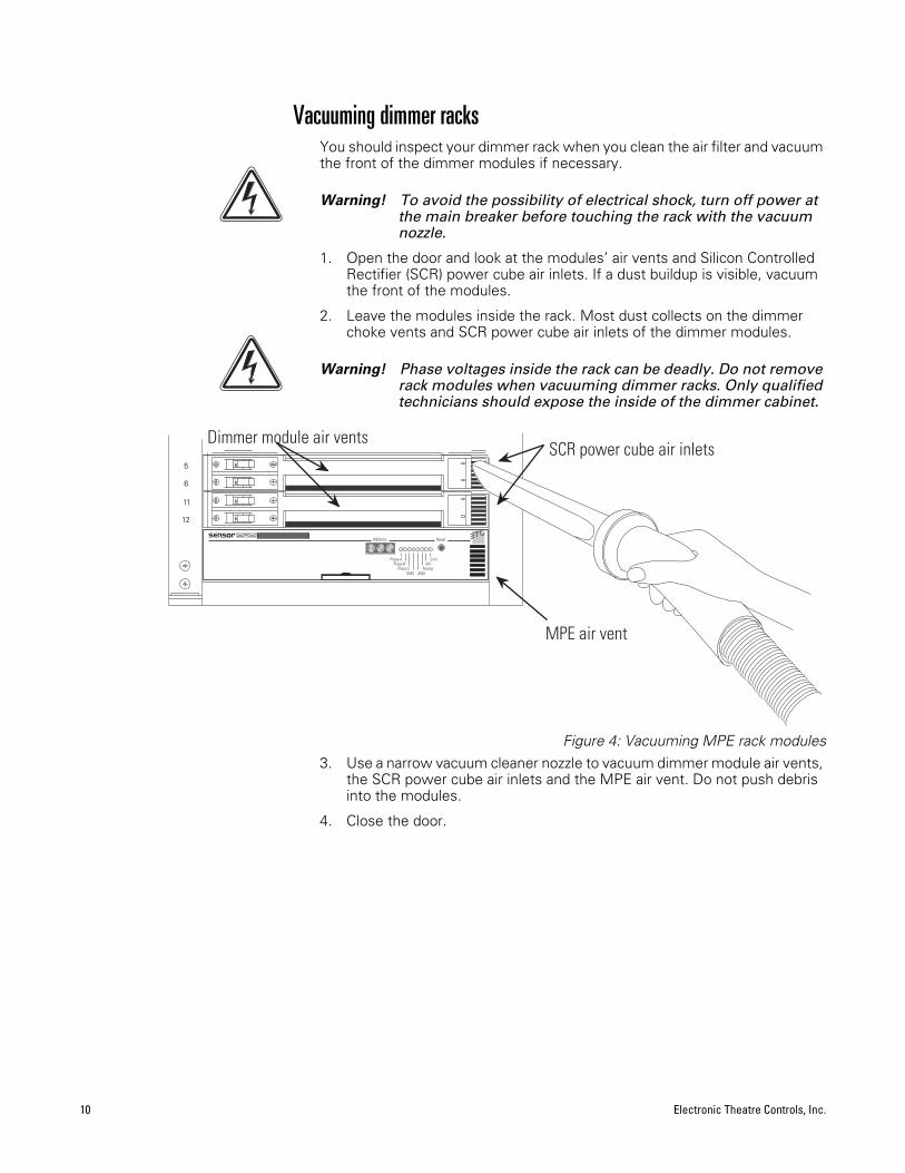
Vacuuming dimmer racks
You should inspect your dimmer rack when you clean the air filter and vacuum the front of the dimmer modules if necessary.
Warning!
To avoid the possibility of electrical shock, turn off power at the main breaker before touching the rack with the vacuum nozzle.
1. Open the door and look at the modules’ air vents and Silicon Controlled Rectifier (SCR) power cube air inlets. If a dust buildup is visible, vacuum the front of the modules.
2. Leave the modules inside the rack. Most dust collects on the dimmer choke vents and SCR power cube air inlets of the dimmer modules.
Warning!
Phase voltages inside the rack can be deadly. Do not remove rack modules when vacuuming dimmer racks. Only qualified technicians should expose the inside of the dimmer cabinet.
Figure 4: Vacuuming MPE rack modules
3. Use a narrow vacuum cleaner nozzle to vacuum dimmer module air vents, the SCR power cube air inlets and the MPE air vent. Do not push debris into the modules.
4. Close the door.
OF
FO
FF
OF
FO
FF12
11
6
5
Dimmer module air vents
MPE air vent
SCR power cube air inlets
AMXAnalog
IASError
Phase CPhase B
DMX
Phase A
Reset
0
1
6
Address

Sensor MPE Dimming User Manual 11
Service
Warning!
Servicing Sensor MPE dimming equipment exposes high amperage power connections inside the rack. Turn off power at the main circuit breaker before servicing your system.
Contacting ETC about equipment problems
If possible, please have this information available before contacting ETC about an equipment problem:
▼
Your location, job name and Sales Order number.
Note:
The Sales Order number on a sticker on the bottom of your rack, visible when you remove the MPE module. See page12 for details.
▼
Any error signals on the MPE status LEDs
▼
Related system problems or equipment failures
ETC Technical Services3030 Laura LaneMiddleton, WI. 53562Phone: 1-800-775-4382
Note:
For the best service results, always tell your service representative you are using the MPE version of Sensor dimming system.
Changing Installation Rack modules
All Sensor MPE rack modules can be easily replaced without tools. Modules slide in and out of their slots and are ready to start dimming immediately.
Although Sensor modules, including the MPE, can be replaced with power on, always turn rack power off at the main circuit breaker before changing them.
Note:
Operating a dimmer rack with open module slots disrupts airflow inside the rack, which can lead to rack overheating.
Using dimmer module circuit breakers
Circuit breakers are turned On and Off or reset using the switch handles on the left side of the dimmer modules.
Note:
Dual density dimmer modules have two circuit breaker switches.
1. Open the dimmer rack door.
2. Put the circuit breaker switch in the desired On or Off position.
▼
Push the handle
left
to turn the dimmer on or reset a tripped breaker.
▼
Push the handle
right
to turn the dimmer off.
Figure 5: Dimmer module circuit breakers
Right turns the dimmer Off
Left turns the dimmer On
Signal
Power
Signal
Power
D20AF
Signal
Power
Signal
Power
D20AF

12 Electronic Theatre Controls, Inc.
Replacing an MPE module
1. Turn off rack power at the main breaker.
2. Open the rack door.
3. Grasp the pull tab centered on the bottom of the MPE and pull the MPE straight out.
Figure 6: Removing an MPE module
4. Duplicate the configuration DIP switch and front panel rotary switch settings from the old MPE to the switches on the new MPE, unless directed to do otherwise by an authorized ETC technician.
5. Firmly press the new MPE module into the correct slot until you feel the connections seat (the module face will be flush with the other modules).
6. Close the Sensor rack door before applying power.
Replacing a dimmer module
1. Turn off rack power at the main breaker.
2. Open the rack door.
3. Grasp the dimmer module by the center of the main air vent and pull the module straight out.
4. Firmly press the replacement dimmer or airflow module into the correct slot until you feel the connections seat (the module face will be flush with the other modules).
5. Close and lock the Sensor rack door before applying power, if possible
Phase C
0
1 6
AMXAnalog
IASError
Phase B
DMX
Phase A
Reset
Address

Sensor MPE Dimming User Manual 13
Internal MPE configuration settings
DIP switch configuration settings
After removing the MPE module you can set the configuration DIP switches for your system.
Note:
Don’t change the switch settings unless they are obviously incorrect, or you are advised to do so by an authorized ETC representative.
Figure 7: Top view of MPE module
1. Set DIP switches
1
,
2
, and
3
to the proper setting based on the modules installed in your rack.
Note:If your rack contains fluorescent modules, or a mix of module types, your MPE must use a custom configuration provided by the factory.
Table 1: Rack configuration DIP switch settings
Rack configuration Channel order
Switch 1 position
Switch 2 position
Switch 3 position
SR6 with three D100 modules 1, 2, 3…Unbalanced off off off
SR6 with six D50 modules 1, 2, 3…Unbalanced off off on
SR6 with six D15/D20 modules 1, 2, 3…Unbalanced off on off
SR12 with six D100 modules 1, 4, 7…Balanced off on on
SR12 with twelve D50 modules 1, 4, 7…Balanced on off off
SR12 with twelve D15/D20 modules 1, 4, 7…Balanced on off on
SR12 with twelve D15/D20 modules 1, 2, 3…Unbalanced on on off
Custom configuration (set at factory) Depends on configuration on on on
Configuration DIP switches Test switchPhase A (F5) Phase B (F4) and Phase C (F3) fuses
S1ON
1 2 3 4 5 6 7 8Figure 8: Configuration DIP
switch settings
These DIP switches control MPE configuration

14 Electronic Theatre Controls, Inc.
Turning on Dimmer Doubling™ 1. Set DIP switch 4 to On (up) to turn on Dimmer Doubling for all modules in
the rack. See Figure 7 on page 13 for DIP switch location.
Turning on input filteringIf you notice an output fluctuation at low levels, particularly when using the AMX/Analog Adaptor box, you can use input filtering to help steady the output. See Figure 7: Top view of MPE module for DIP switch location.
Note:Input filtering reduces system response time, so it should be left off unless a fluctuation problem is noted.
1. Set DIP switch 5 to On (up) to enable input filtering.
Setting the control input typeThe MPE module can accept three different types of control input. Internal DIP switches 6, 7 and 8 should be set to the control type used in your facility. See Figure 7: Top view of MPE module for DIP switch location.
Note:DMX512 input can be enabled with AMX192 or Analog (0-10 Vdc), but AMX192 and Analog input cannot be used together.
Table 2: DIP switch settings to select control type
Test switch operationSwitch S2 sets all dimmer channels to 100 percent intensity, overriding all other switch settings. For normal operation it should be in the Off position. See Figure 7 on page 13 to locate S2.
Caution To avoid overloading your main power supply, turn off all of your dimmer module circuit breakers before setting S2 to On. Use the circuit breakers to test modules one at a time. See Using dimmer module circuit breakers on page 11.
Changing MPE phase fusesThe MPE has three phase fuses:
▼ The phase A fuse, F5, is a 250V, 1.5amp, 5 x 20mm 2AG-type fuse. MPE operating power is drawn through F5. If F5 fails, the MPE will not function.
▼ Phase B (F4) and Phase C (F3) fuses, are 250V, 0.125 amp, 5 x 20mm 2AG-type fuses. If F4 or F3 fail, the MPE will function, but dimmers on the affected phase will not operate. The Sensor rack beacon, MPE Error LED, and affected phase Status LED will flash to signal a problem.
Replacing a phase fuse1. Remove the MPE module (See Replacing an MPE module on page 12).
2. Locate and replace the defective fuse (See Figure 7 on page 13).
3. Replace the MPE module and close the door.
Control type Switch 6 position
Switch 7 position
Switch 8 position
DMX512 off off onAMX192 off on offAnalog (0-10 Vdc) on off off
S2Front of MPE Module
Backswitch
positionsets all
dimmersto full on
Figure 9: Test switch

Sensor MPE Dimming User Manual 15
TroubleshootingYour Sensor MPE system can help you identify system problems with status reporting and diagnostic testing capabilities. You will usually notice a system problem in one of two ways:
▼ The Sensor Beacon on the dimmer rack begins blinking, indicating the MPE has detected a problem. The system may still function normally.
▼ You notice a performance problem. The error beacon may flash, or the problem may be caused by another part of your lighting control system.
If these situations occur, follow these steps to isolate and correct the cause.
Make a preliminary examination of your system1. Check for loose or damaged control cables coming into your dimmer rack.
2. Check tripped breakers on your main circuit breaker panel.
3. Look for obstructions on top or in front of your installation rack that may be blocking rack ventilation.
4. Open the door and look for dust buildup on the air filter or rack modules.
5. Check for tripped dimmer module circuit breakers.
Correct any of these problems you find, press [Reset] on the front of the MPE module and observe the system to see if the problem still exists.
Using the MPE for direct control and testingYou can evaluate switch settings and LED functions or control dimmer levels using MPE Direct Control Mode.
Caution Direct Control Mode interrupts normal dimming. Direct control should only be used by qualified lighting technicians.
Enabling MPE Direct Control ModeYou enable Direct Control Mode with the rotary switches and [Reset] button.
Caution Tests 820 and 850 can set all dimmer levels to 100 percent. Your main power must be able to supply full rack loading.
1. Enter the number of the control mode you want with the rotary switches.
2. Press [Reset] to enter direct control mode. The status LEDs flash on and off from right to left once and out from the center four times.
3. When you finish using direct control, return the system to normal function by pressing [Reset] with the rotary switches in their start address setting.
Switch setting Control mode function
800 Shows DIP switch settings and rotary switch position using the status LEDs
810 Cycles each dimmer channel on and off in numerical order
820 Cycles all dimmer channels from 0 to 100 percent intensity
830 Cycles each dimmer channel from 0 to 100 percent in numerical order
840 Sets dimmer channel selected with rotary switch to 100 percent.
850 Sets all dimmer channels to intensity level set with rotary switches
Address
0
1
6
Figure 10: Setting switches
Turn the switches to set numbers. Example is 016

16 Electronic Theatre Controls, Inc.
800– Evaluating DIP and Rotary switch position and functionAfter you press [Reset], the individual status LEDs will turn on or off according to the combined settings of the front panel rotary switches and eight internal DIP switches. You must neutralize either the internal DIP or front panel switches to completely check the function of the other set.
Checking settings of the internal DIP switchesThis process shows the setting of the internal configuration DIP switches.
1. Set all three rotary switches to 0.
2. The status LEDs show the internal DIP switch settings (See Figure 11.)
Checking rotary switch functioningThis mode allows you to test functioning of each rotary switch.
1. Remove the MPE module. See Replacing an MPE module on page 12.
2. Record the internal DIP switch settings and set them all to Off.
3. Set the rotary switches to 8-0-0, re-insert the MPE and let it reset.
4. Set the rotary switches to 0-0-0. All the LEDs will be dark.
5. Select numbers on the rotary switch you want to test. The four status LEDs on the right will display that number in binary (base 2) format.
6. Return the internal DIP switches and the front panel display to their original settings and re-install the MPE module.
810–Cycling dimmer channels on and offAfter you set the rotary switches to 810 and press [Reset] the MPE begins turning each dimmer channel on and off in numerical progression. You set the cycling speed with the last rotary switch on the right (higher setting = faster speed).
This cycling continues until you end the test by setting the rotary switches back to their original position and pressing [Reset].
820–Fade all dimmer channels up and down
Caution Test 820 will fade all dimmer levels up 100 percent. Your main power must be able to supply full rack loading.
After you set the rotary switches to 820 and press [Reset] the MPE repeatedly fades all dimmer channel levels up to full and back down to zero. You set the fading speed with the last rotary switch on the right (higher setting = faster fade).
This fading continues until you end the test by setting the rotary switches back to their original position and pressing [Reset].
830–Fade individual dimmer channels up and down in numerical orderAfter you set the rotary switches to 830 and press [Reset] the MPE repeatedly fades each dimmer channel level up and down in numerical order. You set the speed with the last rotary switch on the right (higher setting = faster cycle).
This fading continues until you end the test by setting the rotary switches back to their original position and pressing [Reset].
ON
1 2 3 4 5 6 7 8
Phase A
Phase B
Phase CDMX AMX
Analog
IAS
Error
Figure 11: Status LEDinternal Dip switch position
Internal DIP switch positions
Front panel LED indication
Value LED Value LED
0 5
1 6
2 7
3 8
4 9
Figure 12: Binary LED display

Sensor MPE Dimming User Manual 17
840–Set a selected dimmer channel to full intensityAfter you set the rotary switches to 840 and press [Reset] the MPE sets a selected dimmer channel to full intensity. You select the dimmer number with the last two rotary switches on the right.
End the test by setting the rotary switches back to their original position and pressing [Reset].
850–Setting levels for all dimmer channels
Caution Test 850 can set all dimmer levels to 100 percent. Your main power must be able to supply full rack loading.
After you set the rotary switches to 850 and press [Reset] the MPE sets all dimmer channels to a selected level between 0 – 100 percent. You set the level with the rotary switches. Any switch setting higher than 100 sets intensity to full.
End the test by setting the rotary switches back to their original position and pressing [Reset].
Check system status with the MPE front panel displayIf the preliminary check doesn’t find the problem, you can use the MPE front panel display to get more information.
1. Open the dimmer rack door and look at your MPE module LED display.
Note:If you have multiple racks, look for a rack with a flashing or dark Sensor beacon. If none of the beacons are flashing, check all your racks.
2. The basic display tells you if there is a line phase or control signal problem:
▼ If the MPE cannot detect a line phase or the voltage is out of tolerance (between 90 – 140Vdc) the status LED for that phase will be dark. Check the MPE phase fuses (See Replacing a phase fuse on page 14).
Note:If Phase A is out of tolerance, the MPE will be shut off.▼ If the MPE is programmed for AMX192 or DMX512 control input, the
indicator LEDs for those signal will be lit when the signals are present and valid. If a signal fails, its status LED will flash. Make sure your control system is turned on and properly connected.
▼ MPE systems programmed for Analog control input will show a lit indicator LED at all times. Because Analog input voltage can be 0 during normal operation, the MPE cannot test for a valid signal.
Phase A
Phase B
Phase CDMX AMX
Analog
IAS
Error
When the MPE detects a control signalproblem, the associated Status LEDbegin flashing
Figure 14: LED error indication
18 Electronic Theatre Controls, Inc.
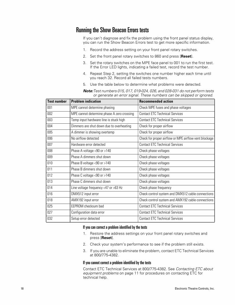
Running the Show Beacon Errors testsIf you can’t diagnose and fix the problem using the front panel status display, you can run the Show Beacon Errors test to get more specific information.
1. Record the address setting on your front panel rotary switches.
2. Set the front panel rotary switches to 860 and press [Reset].
3. Set the rotary switches on the MPE face panel to 001 to run the first test. If the Error LED lights, indicating a failed test, record the test number.
4. Repeat Step 2, setting the switches one number higher each time until you reach 32. Record all failed tests numbers.
5. Use the table below to determine what problems were detected.
Note:Test numbers 015, 017, 019-024, 026, and 028-031 do not perform tests or generate an error signal. These numbers can be skipped or ignored.
If you can correct a problem identified by the tests1. Restore the address settings on your front panel rotary switches and
press [Reset].
2. Check your system’s performance to see if the problem still exists.
3. If you are unable to eliminate the problem, contact ETC Technical Services at 800/775-4382.
If you cannot correct a problem identified by the testsContact ETC Technical Services at 800/775-4382. See Contacting ETC about equipment problems on page 11 for procedures on contacting ETC for technical help.
Test number Problem indication Recommended action
001 MPE cannot determine phasing Check MPE fuses and phase voltages
002 MPE cannot determine phase A zero crossing Contact ETC Technical Services
003 Temp input hardware line is stuck high Contact ETC Technical Services
004 Dimmers are shut down due to overheating Check for proper airflow
005 A dimmer is showing overtemp Check for proper airflow
006 No airflow detected Check for proper airflow or MPE airflow vent blockage
007 Hardware error detected Contact ETC Technical Services
008 Phase A voltage <90 or >140 Check phase voltages
009 Phase A dimmers shut down Check phase voltages
010 Phase B voltage <90 or >140 Check phase voltages
011 Phase B dimmers shut down Check phase voltages
012 Phase C voltage <90 or >140 Check phase voltages
013 Phase C dimmers shut down Check phase voltages
014 Line voltage frequency <47 or >63 Hz Check phase frequency
016 DMX512 input error Check control system and DMX512 cable connections
018 AMX192 input error Check control system and AMX192 cable connections
025 EEPROM checksum bad Contact ETC Technical Services
027 Configuration data error Contact ETC Technical Services
032 Setup error detected Contact ETC Technical Services
Sensor MPE Dimming User Manual 19
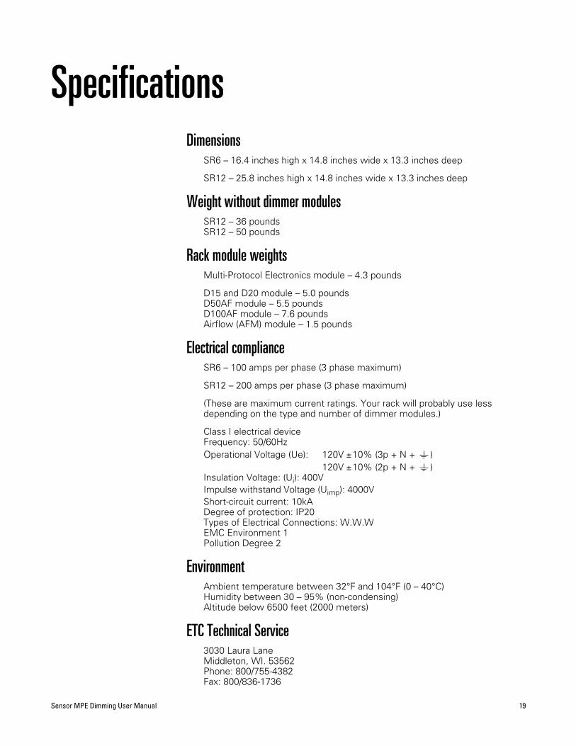
SpecificationsDimensions
SR6 – 16.4 inches high x 14.8 inches wide x 13.3 inches deep
SR12 – 25.8 inches high x 14.8 inches wide x 13.3 inches deep
Weight without dimmer modulesSR12 – 36 poundsSR12 – 50 pounds
Rack module weightsMulti-Protocol Electronics module – 4.3 pounds
D15 and D20 module – 5.0 poundsD50AF module – 5.5 poundsD100AF module – 7.6 poundsAirflow (AFM) module – 1.5 pounds
Electrical complianceSR6 – 100 amps per phase (3 phase maximum)
SR12 – 200 amps per phase (3 phase maximum)
(These are maximum current ratings. Your rack will probably use less depending on the type and number of dimmer modules.)
Class I electrical deviceFrequency: 50/60HzOperational Voltage (Ue): 120V ±10% (3p + N + )
120V ±10% (2p + N + )Insulation Voltage: (Ui): 400VImpulse withstand Voltage (Uimp): 4000VShort-circuit current: 10kADegree of protection: IP20Types of Electrical Connections: W.W.WEMC Environment 1Pollution Degree 2
EnvironmentAmbient temperature between 32°F and 104°F (0 – 40°C)Humidity between 30 – 95% (non-condensing)Altitude below 6500 feet (2000 meters)
ETC Technical Service3030 Laura LaneMiddleton, WI. 53562Phone: 800/755-4382Fax: 800/836-1736

Electronic Theatre ControlsNorth America Europe Asia3030 Laura Lane 5 Victoria Industrial Estate • Victoria Road Room 605-606, Tower III, Enterprise Square,Middleton, Wisconsin 53562 • USA London W3 6UU • England 9 Sheung Yuet Road, Kowloon Bay, Kowloon • Hong Kong Tel: (+1) 608 831 4116 • Fax: (+1) 608 836 1736 Tel: (+44) 181 896 1000 • Fax: (+44) 181 896 2000 Tel: (+852) 2799 1220 • Fax: (+852) 2799 9325
World Wide Web: http://www.etcconnect.com • Email: [email protected] Copyright ©1998revised 3/98 Specifications subject to change. 7051M1009


