Sensor fusion for motion processing and...
34
Sensor fusion for motion processing and visualization Ali Baharev, PhD TÁMOP 4.2.2 “Szenzorhálózat alapú adatgyűjtés és információfeldolgozás” workshop April 1, 2011 Budapest, Hungary
Transcript of Sensor fusion for motion processing and...

Sensor fusion for motion processing and visualization
Ali Baharev, PhD
TÁMOP 4.2.2 “Szenzorhálózat alapú adatgyűjtésés információfeldolgozás” workshop
April 1, 2011Budapest, Hungary

What we have - Shimmer Wireless Sensor Platform
Sensors● 3-axis accelerometer, Freescale MMA7260Q ±1.5/2/4/6g (1g≈9.81m/s2)
● 3-axis gyroscope; two integrated dual-axis angular rate gyroscopes InvenSense 500 series
● No compass
Processing● MSP430™16-bit Ultra-Low Power MCU @ 8 MHz● 10Kbyte RAM, 48Kbyte ROM● 8 Channels of 12bit A/D
Battery● Integrated Li-ion 280 mAh, 3.7 V
x
y
z

What we have - Shimmer Wireless Sensor Platform (continued)
Radios● 2.4 GHz IEEE 802.15.4 Chipcon CC2420
● Mitsumi WML-C46N CSR based Class 2 Bluetooth Radio
Storage● 2 GB Micro SD card
Form factor● Small form factor● 50mm x 25mm x 12.5mm ● Light weight: 15 grams
Software● TinyOS event driven OS for WSN● Open source

What we want - Gait analysis
● Analysis of measurable parameters of human gait● From the output of the sensors –> reconstruct the orientation of the limbs in time
●The orientation, described by angles and position

Showing live demo
Qt cross-platform GUI,C++ programming language
Open-source
For medical use (research)
Elbow flexion (left and right arm)
Results are presented asanimation (OpenGL)

What is the competitive edge of the Shimmer platform?
Competitive if:
Video cameras / ultrasound measuring systems are not applicable; for example outdoor activities
Multiple sensors are needed
We cannot or we do not want to process the data real-time
KinectGuiness record, 8m in 2months
Smart phones, Android devices

So how can we compute it?
?
From the output of the sensors –> reconstruct theorientation of the limbs intime
x
y
z

What does the output of the sensors look like?
Raw accelerometer data
Raw gyroscope data
●The sensor was placed on the desktop then turned over
● Output is not zero even in the static case
● Axes are not neces-sarily perpendicular
● Needs calibration, linear transfer func-tion is assumed
● Accelerometer mea-sures gravity even if the mote is stationary

What does the output of the sensors look like?
Calibrated accelerometer data
Calibrated gyroscope data
●The sensor was placed on the desktop then turned over
● Output is not zero even in the static case
● Axes are not neces-sarily perpendicular
● Needs calibration, linear transfer func-tion is assumed
● Accelerometer mea-sures gravity even if the mote is stationary

What can we compute from acceleration?
In the static case constant 1g pointing downwards is measured
The angle between an axis of the device and the horizontal plane can be computed – Tilt angles
We could even compute orientation if we had a compass
(accelerometers have no idea where north is)
x
yz
g

Tilt angles computed from the acceleration data
Tilt angles computed from the measured acceleration (alpha) practically coincides with the true tilt angles (beta) if the mote is not acceleratingWe get weird spikes when the sensor is accelerating
Workaround: low-pass filter, works but poor transient response, lags

What can we compute from the gyro data?
Gyroscopes measures angular rate in the mote frame of reference
Angles can be computed by numericalintegration:
Good news: not influenced by accelerationor gravity; fast, responsive, not subject to lagOrientation s.t. initial orientation can becomputed
DriftThe integrated effects over time of a slowlyvarying offset and noise. The drift must be eliminated, requires an external reference vector that does not drift.
(simplified!) t =0∫0
t
d

Putting it all together – drift cancellation
Both accelerometer and gyro data can be used to compute angles
Accelerometer provides a reference vector, gravity, that does not drift (long-term) but has poor transient response
Gyro data is excellent for computing orientation (short-term), gives fast transient response but needs reference vector that does not drift
?keep the good
from bothsomehow
Accelerometer(long-term)
Gyro(short-term)
Orientation
Our approach: offline, nonlinear regression for each recordCustom C++ solver using IPOPT
Future plans
Appropriate uses:
● Outdoor activities
● Multiple sensors
● Off-line processing
Plans:
● Rowing
● Running

Acknowledgements
Prof. László Hatvani: technical discussion
Péter Ruzicska: colleague
Miklós Maróti: supervising the research
The presented work was supported by the Grant TÁMOP-4.2.2/08/1/2008-0008
References
W. Premerlani and P. Bizard; Direction Cosine Matrix IMU: Theoryhttp://gentlenav.googlecode.com/files/DCMDraft2.pdf
Shane Colton; The Balance Filter, A Simple Solution for Integrating Accelerometer and Gyroscope Measurements for a Balancing Platform; Chief Delphi white paper, 2007.http://web.mit.edu/scolton/www/filter.pdf

Further slides, not presented

Live demo – fooling the application
After drift cancellation, only the gyro data is used to computeorientation
Position is not computed
We can fool the application by rotating the sensor around a point
It still gives us a proper elbow flexion

Sensors: accelerometer
Accelerometer● 3 Axis Accelerometer, Freescale MMA7260Q● Sensitivity: 800 mV/g @ 1.5g● 12 bit analogue digital converter –> integer number● Resolution: 1.5g1.5g/212
≈7⋅10−4 g /unit
x
y
z 0-1g 1g
Sensitivity axis
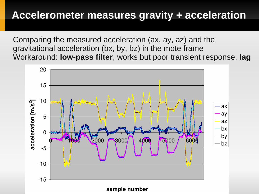
Accelerometer measures gravity + acceleration
Comparing the measured acceleration (ax, ay, az) and the gravitational acceleration (bx, by, bz) in the mote frameWorkaround: low-pass filter, works but poor transient response, lag

Static calibration of the accelerometer
Assumption: measured value is a linear function of the acceleration (linear transfer function)
Calibration: find the gain matrix (9 unknowns) and offset vector (3 unknowns)
acceleration [m/s2] = gain∙(measured value) − offset
Place the mote on each of its six side and record the outputacceleration: (±1g, 0, 0); (0, ±1g, 0); (0, 0, ±1g)
Gives an overdetermined system of linear equations (18 equations and 12 unknowns); linear least-squares, analytic solution (SVD)

Sensors: accelerometer and gyroscopes
Accelerometer● 3 Axis Accelerometer, Freescale MMA7260Q● Sensitivity: 800 mV/g @ 1.5g● 12 bit analogue digital converter –> integer number● Resolution:
Gyroscope● 2 integrated dual-axis, InvenSense 500 series● Full scale range: +/- 5000 deg/s● Sensitivity: 2 mV/deg/s
Output in the static case● Offset (not zero), actual value depends mainly on chip, plus temperature, etc.
● Accelerometer: constant value corresponding to 1g (gravity of Earth)
1.5g1.5g/212≈7⋅10−4 g /unit

Sensors: gyroscopes
Gyroscope● 2 integrated dual-axis, InvenSense 500 series● Measures angular rate● Full scale range: +/- 5000 deg/s● Sensitivity: 2 mV/deg/s● 12 bit ADC –> integer number
Output in the static case● Offset (not zero), actual value depends mainly on chip, plus temperature, etc.
● Accelerometer: constant value corresponding to 1g (gravity of Earth)

Calibration of the gyroscopes
Calibration: find the gain matrix (9 unknowns) and offset vector (3 unknowns; linear transfer function)
angular rate [rad/s] = gain∙(measured value) − offset
Place the mote on each of its six side and record the outputangular rate: (±45rpm, 0, 0); (0, ±45rpm, 0); (0, 0, ±45rpm)
A small error in the offset accumulates –> huge error in orientation over time, drift

Can we compute speed or position from a(t)?
The a(t) vector is measured in the mote frame of referencebut we would like to track the mote in the earth frame.
Transformation is needed from one frame to the other –> rotation
v t =v 0∫0
t
a −gd
r t =r 0∫0
t
v d
x'
y'
z'
x
y
z
earthframe
moteframe
a

Rotation
We need rotation to transforms the acceleration vectors from the mote frame of reference to the earth reference
Rotation: linear transformation, preserves lengths of vectors and angles between vectors
x'
y'
z'
x
y
z
[r xx' r yx ' r zx '
r xy' r yy ' r zy '
r xz ' r yz' r zz']
x y zx 'y 'z '
Rotation matrix

Rotation (continued)
● Rotation matrix
● Euler angles
● Angle/axis
● Quaternion
Rotation is uniquely defined by 3 angles
Rotation representations

Performance comparisons of rotation methods
Storage requirements
Performance comparison of rotation chaining operations
Performance comparison of vector rotating operations
matrix 9
quaternions 4
angle/axis 3
multiplies add/substr. total
matrix 27 18 45
quaternions 16 12 28
multiplies add/substr. sin/cos total
matrix 9 6 0 15
quaternions 21 18 0 39
angle/axis 23 16 2 45
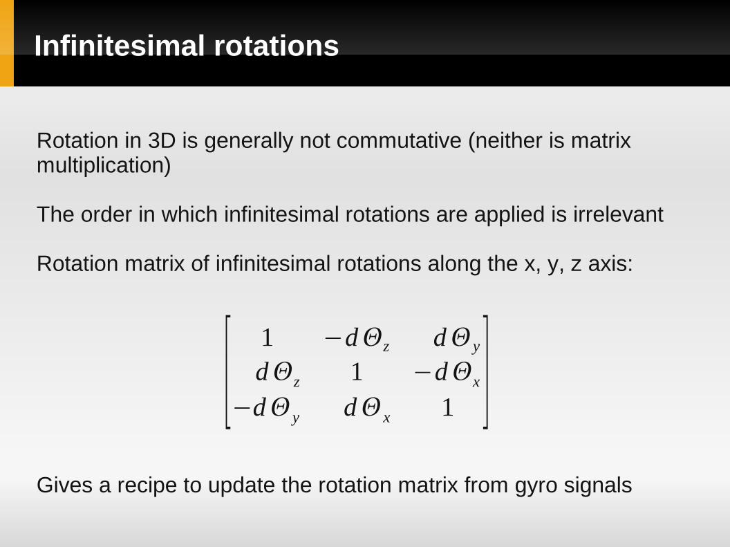
Infinitesimal rotations
Rotation in 3D is generally not commutative (neither is matrix multiplication)
The order in which infinitesimal rotations are applied is irrelevant
Rotation matrix of infinitesimal rotations along the x, y, z axis:
Gives a recipe to update the rotation matrix from gyro signals
[1 −dz dy
dz 1 −dx
−dy dx 1 ]

Updating the rotation matrix from gyro signals
W. Premerlani and P. Bizard; Direction Cosine Matrix IMU: Theory
Sources of errors● Finite time step● Quantization error: finite digital representation
The rotation matrix must be corrected –> renormalization at each point (no divisions or square roots)
R tdt =R t [1 −dz dy
dz 1 −dx
−dy dx 1 ]dx=x dtd y=y dtdz=z dt

Drift cancellation off-line with nonlinear regression
Off-line, operates on the whole data set but manipulates only12 variables: 3x3 gain matrix and offset vector of the gyro
angular rate [rad/s] = gain∙(measured value) − offset
Assumption: ‘On average’ the measured acceleration points into the same direction (gravitational acceleration).
A nonlinear programming problem is solved
variables: gyro gain and offset
max∣∑i=0
N
Riai∣R 0 =IR i=R i−1G i−1 for i=1NG i : from gyro signals

Software
● NLP, a nonlinear programming problem to be solved
● IPOPT, general purpose NLP solver (line search filter method) remarkably robust
● C++ API is used, only the objective has to be implemented
● Automatic differentiation (AD): the gradient is not approximated with numerical differentiation but automagically computed with AD (our own C++ library)
● L-BFGS (approximates the inverse Hessian matrix) to further speed up the computations

On-line methods for sensor fusion
Perhaps the most popular one is the Kalman Filter
It is an on-line method that manipulates each sample
Good introduction with examples: SIGGRAPH Course Pack
Kalman filter is difficult to understand
Much simpler approach is the Complementary Filter with similar results (see filter.pdf)

Computing position
Now, the measured values in the mote frame can be transformed to the earth frame
Horrible error, computing the double integral is notoriously difficult
v t =v 0∫0
t
a −gd
r t =r 0∫0
t
v d x'
y'
z'
x
y
z