Sensor Failure Detection for Jet Engines Using Analytical ... · SENSOR FAILURE DETECTION FOR JET...
25
NASA Technical Memorandum 83695 AIAA-84-1452 Sensor Failure Detection for Jet Engines Using Analytical Redundancy Walter C. Merrill Lewis Research Center Cleveland, Ohio Prepared for the Twentieth Joint Propulsion Conference cosponsored by the AIAA, SAE, and ASME Cincinnati, Ohio June 11-13, 1984 NASA https://ntrs.nasa.gov/search.jsp?R=19840016517 2018-07-28T09:55:08+00:00Z
Transcript of Sensor Failure Detection for Jet Engines Using Analytical ... · SENSOR FAILURE DETECTION FOR JET...
NASA Technical Memorandum 83695AIAA-84-1452
Sensor Failure Detection for Jet EnginesUsing Analytical Redundancy
Walter C. MerrillLewis Research CenterCleveland, Ohio
Prepared for theTwentieth Joint Propulsion Conferencecosponsored by the AIAA, SAE, and ASMECincinnati, Ohio June 11-13, 1984
NASA
https://ntrs.nasa.gov/search.jsp?R=19840016517 2018-07-28T09:55:08+00:00Z
CMI
SENSOR FAILURE DETECTION FOR JET ENGINES USING ANALYTICAL REDUNDANCY
Walter C. MerrillNational Aeronautics and Space Administration
Lewis Research CenterCleveland, Ohio 44135
SUMMARY
Analytically redundant sensor failure detection. Isolation, and accommoda-tion techniques for gas turbine engines are surveyed. Both the technology baseand demonstrated concepts are discussed. Results from twenty five papers andreports are reviewed which document the development of the field from 1974 tothe present. Demonstrations of analytically redundant techniques using enginesimulations or full scale engines are Included. Various differences among thethree demonstrated approaches are discussed. Finally, ongoing Government pro-grams are described.
INTRODUCTION
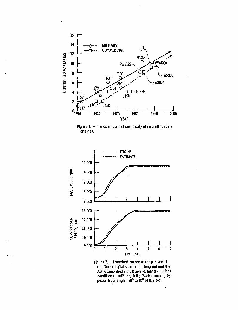
This paper surveys the use of analytical redundancy to Improve turbineengine control system reliability. As shown 1n figure 1 an Increase 1n controlcomplexity has occurred 1n recent years and 1s expected to continue. ThisIncreased complexity has made 1t difficult to build reliable, low cost, lowweight hydromechanlcal controls. On the other hand microprocessor based digi-tal electronic technology allows complex control systems to be built with lowcost and weight. However, these digital electronic controls do not have thematurity and therefore the demonstrated reliability of hydromechanlcal enginecontrol systems.
A recent study of fault tolerant electronic engine controls (ref. 1) showsthat sensor redundancy will be required to achieve adequate control systemreliability. There are two types of sensor redundancy, hardware and analyti-cal. Hardware redundancy (HR) uses multiple sensors to measure the same enginevariable. Analytical redundancy (AR) uses a reference model of the engine toprovide redundant estimates of a measured engine variable. HR 1s Insensitiveto failure type, hard or soft, since any discrepancy between two like sensorsIndicates a failure. (Hard failures are out-of-range or large 1n-range fail-ures. Soft failures are small 1n-range or drift failures.) AR, however, dis-tinguishes failure types. HR results 1n more costly, heavier, less practical,and less reliable systems than do various AR strategies (ref. 1). Consequentlymany researchers have Investigated AR strategies.
The first objective of this paper 1s to survey the application of AR tothe detection, Isolation, and accommodation (DIA) of sensor failures for gasturbine engines. HR strategies are not covered. First, this survey reviewsthe theoretical and application papers which form the technology base of tur-bine engine AR research. Second, the status of four major, ongoing, applicationefforts are discussed. An analysis of this survey Indicates some current tech-nology needs. The second objective of this paper 1s to present NASA's currentprograms which address these technology needs.
AR Technology Base
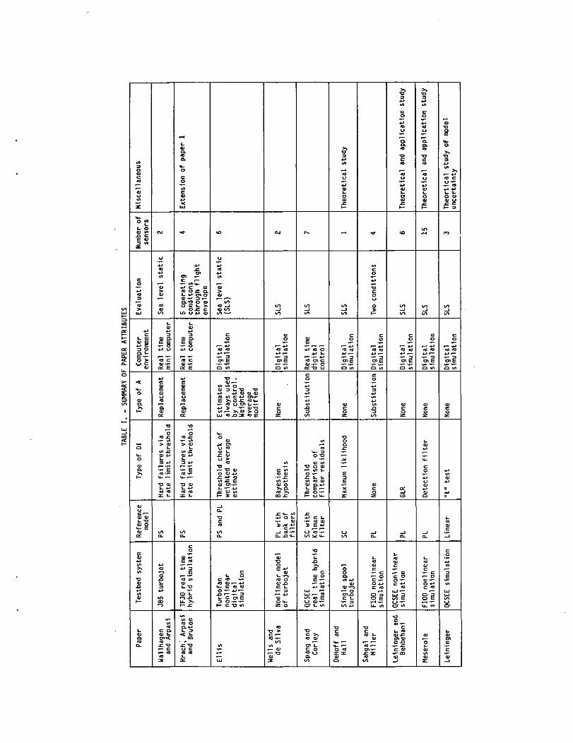
This section describes those papers that document the AR technology base.Sixteen papers are considered. The papers are reviewed In essentially chrono-logical order. The attributes of each paper are discussed In this section.These attributes are summarized In table I.
Uallhagen and Arpasl (ref. 2) presented the first (April 1974) use ofsensor AR to Improve engine control system reliability. A J85, single spool,turbojet with two sensed variables and three controlled variables was testedat a sea level, static condition. The Inputs were compressor variable geom-etry,, fuel flow, and exhaust nozzle area. The sensors were a magnetic pickupfor rotor speed and a high response gage tranducer for compressor static dis-charge pressure. Failure detection was accomplished by comparing the rate ofchange of the sensed variables with predetermined limits. Four consecutiveout of range rates declared a failure. Since each sensor was tested for cata-strophic, I.e., hard failure only. Isolation 1s Immediate. Failures are accom-modated by replacement of the failed sensed value with a synthesized estimate.This synthesized variable 1s obtained from a tabulation of the synthesizedvariable as a function of remaining engine variables. Different tables werestored for steady-state and acceleration conditions. No explicit dynamicalrelationships were Included.
The DIA logic was Implemented 1n fixed point assembly language on a mini-computer. The Implementation executed In a 15 msec time frame which allowedreal-time Interaction with the control. Testing 1n a sea level static teststand compared Idle to full power step responses of rotor speed and thrust.For single failures steady-state speed was held to within 1 percent of Itsfinal value and 92 percent of maximum thrust was achieved. For two sensorfailures steady-state speed was approximately 99 percent of Its final unfa11edvalue and thrust was 87 percent of maximum. Time to accelerate, however, hadto be Increased from 3 to 30 sec. Failures were Induced at 50 percent powerduring a transient. Detection was reliable. The system also allows self-healing. An Interesting feature of the DIA logic was Its ability to learn, online, all the data necessary to function. In a companion paper, Hrach, Arpasl,and Bruton (ref. 3) used a real-time nonlinear hybrid computer simulation of atwo spool turbofan, the TF30-P-3 engine to demonstrate the DIA logic ofreference 1 over a wide operating range. Four sensed variables; high pressurerotor speed, high and low pressure compressor discharge static pressures, andnozzle total pressure, and five Inputs main fuel flow, nozzle area, afterburnerfuel flow, and two compressor stage bleeds were considered. Again hard failuredetection and Isolation were obtained by Individual rate checks.
Accommodation was achieved by replacement with averaged synthesized vari-ables which were a function of the remaining good sensors (1,2,or 3). Synthe-sized variables were obtained from tabulations. However, the data were nowstored as corrected values to allow a wide operating range. Data for thetables were collected at two operating points.
A real-time Implementation of this DIA logic was programmed using assemblylanguage 1n a minicomputer using a frame time of about 25 m/sec. Storage re-quirements Include 4K Bytes for the logic and 0.2K Bytes for the tables. Thelogic was tested at 5 selected operating points (which Include the 2 designpoints). Acceptable operation with no limit violations and approximately thesame thrust was obtained for operation with 1, 2, or 3 of the 4 sensors failed.
For afterburning operation of the engine acceptable control was possible foronly a single failure and with a severe rate limit on accelerations. Thislogic also Incorporated learning or adaptive logic.
Ellis (ref. 4) (January 1975) studied the use of AR techniques using anonlinear digital simulation of a two spool turbofan engine. The engine hadfive measured variables and two Independent controlled variables. The OIAphilosophy of this paper centers around estimates of the measured variables.First a mult1var1able linearized mapping (no explicit model dynamics) of cor-rected measurements to estimates 1s found. Since the engine has only two In-dependent controls, 1t 1s assumed that only two measurements are required togenerate an estimate. Taking unordered pairs of the 5 measured variablesyields 10 estimates of each measured variable. A weighted average estimate 1sobtained by combining these ten-component estimates each weighted by Its rela-tive accuracy. Detection and Isolation are accomplished by a threshold checkon both sides of each weighted average estimate. If a weighted estimate 1soutside of the threshold corridor then all weighting factors associated withthis estimate are set to zero. Weighted estimates are used by the control atall times. Only the weightings change as failures occur. Thresholds for theweighted estimates are obtained from sensor error statistics assuming Gaussiandistributions.
The next contribution to this area 1s documented 1n four reports bydeSllva (refs. 5 and 6) and Wells (refs. 7 and 8). This series of reportsapplies Bayeslan hypothesis testing to the detection of engine sensor failures.The engine studied 1s a simple turbojet with two outputs, speed and thrust andone Input, fuel flow. A second order pseudollnear (PL) model of the enginewas used on a mainframe computer to evaluate detection performance. A PL modelconsists of a dynamical, linear state space structure. However, Individualcoefficients within the linear structure vary as a nonlinear function of thestate.
Bayeslan hypothesis testing 1s Implemented by 1) defining a risk function,and 2) determining from measured data the hypothesis that minimizes this risk.This risk function defines the penalty associated with selecting a false hy-pothesis. Assuming Gaussian noise statistics, the Bayeslan hypothesis 1s alsoprobabilistically most likely given the measured data. A "bank" of Kalmanfilters, one per hypothesis, used measured data and an engine model to generatestate estimates and filter residuals. The hypothesis associated with the mostUkely set of residuals as determined by a likelihood ratio test was taken aslie true hypothesis. The mode of operation associated with this hypothesis(failed speed sensor, no failure, etc.) was assumed true. The approach workedwell 1n simulation studies of this simple case. This work represents the firstapplication of AR to turbine engines based upon modern control theory. Diffi-culties with this approach Include the requirement of a different Kalman filterfor each failure mode hypothesis.
In June 1977 Spang and Corley (ref. 9) published an application of ARtechniques as applied to the Quiet, Clean, Short Haul, Experiment Engine orQCSEE. This engine has seven measurements, fuel flow, compressor stator angle,fan speed, compressor speed, compressor discharge temperature and pressure,and turbine discharge temperature. Engine controls Include fuel flow valvecurrent and compressor stator blade torque motor current. In this study anextended Kalman filter approach was used to generate state estimates and resid-uals. A simplified nonlinear component model which 1s valid throughout the
engine operating envelope and a simplified feedback gain matrix operating onengine measurements were used to update the filter estimates and residuals.
Sensor failures were detected and Isolated by a threshold comparison ofthe Individual residual components. Thresholds were determined by sensor noisestatistics. Only hard failures are considered. To accommodate failures,faulty measured values are replaced by sensor estimates from the filter. Theapproach was successfully demonstrated on a detailed, real-time, nonlinearhybrid computer simulation of the engine. The detection, accommodation andcontrol logic was Implemented 1n a microprocessor-based control also In real-time. Successful operation for single hard sensor failures was demonstratedat sea level static conditions for power chops and bursts 1n the Idle to fulltake-off power range. This work, referred to as Failure Indication and Correc-tive Action or PICA, serves as the theoretical foundation for a significantportion of the work 1n the application of AR to turbine engines. Further ap-plications based on FICA are given 1n a subsequent section.
Next, DeHoff and Hall (ref. 10) reported a largely theoretical study thatdeveloped a unified framework to achieve engine performance monitoring, trend-Ing, and sensor fault OIA. This framework Is based upon maximum likelihoodstate and parameter estimation methods. A simple turbojet example was used toIllustrate the application of a maximum likelihood based, on line, sequentialprocessing, parameter estimation algorithm to the detection of sensor failures.
Sahgal and Miller (ref. 11) report on the design of a full order observerthat reconstructs fan turbine Inlet temperature for an F100 engine. The ob-server 1s based upon a 5th order scheduled state space model with four Inputs,fuel flow, nozzle area and compressor and fan variable geometries and fouroutputs, fan and compressor speed, and compressor discharge temperature andpressure. Observer performance 1s compared with a full nonlinear digitalsimulation of the engine at sea level static conditions. The reconstructedtemperature tracks the actual temperature quite well. The analytical studyproposes to use the reconstructed temperature to accommodate for fan turbineInlet sensor failures.
The next three papers (refs. 12 to 14) by Le1n1nger and Behbehanl reportthe application of the generalized likelihood ratio (GLR) technique to theQCSEE. The GLR technique 1s a hypothesis based test with the time and type offailure unknown. Under linear, Gaussian assumptions, 1f the Kalman-Bucy filterresiduals are found to be nonwhlte, a failure 1s declared. Next, various like-lihood ratios are compared to determine the most probable failure time andtype. The GLR method was used to detect and Isolate hard and soft failures.Both single and multiple actuator and sensor failures were considered.
Detection and Isolation studies were conducted by simplified simulationof an under the wing QCSEE. This simulation Included six outputs, fan andcompressor speeds, engine Inlet static pressure, fan Inlet duct static pres-sure, combustor pressure and compressor discharge pressure and three Inputs,fuel metering valve position, fan nozzle actuator position, and fan pitchangle. A linearized, eight state model was used 1n the Kalman-Bucy filter.Successful detection and Isolation of multiple sensor and actuator failureswith noisy sensors and Imperfect modeling were demonstrated. Accommodation bycontrol reconfiguration using nonsquare MultlvaHable Nyqulst Array methodswas proposed. Designs were obtained but not demonstrated by simulation.
A doctoral dissertation by Meserole (ref. 15) uses detection filter theoryto design a detection filter that detects sensor failures 1n an F100 engine.Like the Kalman filter, the detection filter Incorporates a dynamic processmodel and generates error residuals. However, unlike the Kalman filter a de-tection filter 1s designed to respond to a component failure with a residualthat has a fixed, usually unique direction. Also this direction 1s Independentof failure mode. Thus, sensor failures can be detected and Isolated by detect-ing the occurrence of these fixed direction residuals. A sixth order state-space linear model with scheduled coefficients 1s used 1n the detection filter.Filter operation and detection capability are demonstrated using a detailednonlinear digital simulation of the FIDO engine. Fifteen components arechecked for failure, the Inlet pressure and temperature sensors, the fan andcompressor speed sensors, the burner and augmentor total pressure sensors, thefan outer diameter discharge and turbine Inlet total temperature sensors, thefuel system, the nozzle, bleed, fan guide vane, and compressor stator vaneactuators, and the high and low pressure turbines. Five Inputs are considered,fuel flow, nozzle area, fan guide vane and compressor stator vane positions,and bleed. Filter performance was studied for sensor failures and componentchanges (failures) at sea level static conditions for bias and scale factorchanges. Failures were detected for 2 percent to 5 percent changes 1n one ormore output measurements. Minimum failure size for successful Isolation 1ssummarized by component In table II.
The final paper to be discussed 1n this section, by Le1n1nger (ref. 16)examines the Impact of an Inaccurate model on Innovations-based detection andIsolation procedures. The paper demonstrates that model Inaccuracies appearas biases 1n the Innovations (residuals). These biases are Identified by a"student t" test. The "student t" test 1s then related to a recursive GLRdetector using a sequentially updated Kalman filter. Model bias error Is re-moved from the Innovations data to remove the effect of model degradation andto allow more accurate soft and hard failure detection. Also, a finite widthwindow sequential "t" test 1s used to update the bias term and provide a meansof sensor failure detection and Isolation. The theory was applied to aneighth order linear model of the QCSEE. Model eigenvalues were perturbed by10 percent to simulate model error. The "t" test successfully removed thebias, tracked a sensor drift followed by a low frequency sinusoidal sensorbias, and exhibited a fa1l-heal-fa1l detection pattern for the sinusoidal test.
AR Technology Development
Based upon the encouraging, but preliminary results of the AR technologybase, several technology development programs were begun. The overall objec-tive of these programs 1s the full scale engine demonstration of Improved con-trol system reliability using AR technology. Four Important AR developmentprograms are discussed 1) Advanced Detection, Isolation, and Accommodation(ADIA), 2) Energy Efficient Engine (E3) FICA, 3) Full Authority DigitalElectronic Control (FADEC) FICA, and 4) Digital Electronic Engine Control(DEEC) sensor DIA.
ADIA
The objective of the ADIA program Is to demonstrate a viable DIA conceptbased upon advanced methodoHgles. The ADIA program consists of three parts:
development, real-time evaluation, and demonstration. The NASA Lewis ResearchCenter provides overall program sponsorship and technical direction. Prattand Whitney Aircraft, and their subcontractor, Systems Controls Technology,developed the ADIA algorithm. A real-time hybrid computer based evaluationand a full scale engine demonstration are currently being performed by theNASA Lewis Research Center. Each of these program parts Is discussed below.
The development of the ADIA algorithm 1s reported by Seattle, et al.(refs. 17 and 18). Here advanced detection and filtering methodologies werecompared to develop a viable ADIA concept. Comparisons were made on an FIDOengine and FIDO Mult1var1able Control (ref. 19) testbed system. The type andseverity of sensor failures were carefully defined. Typical state-of-the-arttransducers were selected. Failure characteristics were defined and quanti-fied according to the predominant failure categories of out-of-range, drift,and noise. Next, a Failure Mode and Effects Cr1t1cal1ty Analysis (FMECA) wasconducted to classify the various failure modes as critical or noncrltlcal.Critical failures result 1n surge, a 10 percent or larger thrust variation, ora rotor overspeed. This classification was accomplished over the full operat-ing range of the F100 engine. Five competing DIA concepts were developed bycombining available detection and filtering technologies. These five conceptswere specifically formulated to span as many applicable technologies aspossible.
Since competing technologies were to be compared, a scoring system wasdeveloped. The scoring system evaluated the concepts for 1) PerformanceCriteria - transient and steady-state minimum operation requirements, 2)Detection Performance - detection and Isolation effectiveness, and 3) Figuresof Merit - qualitative benefits of bettering the Performance Criteria. Usingthe scoring system and a simplified simulation of the testbed system, the fiveconcepts were screened. Two concepts were selected for a more detailed com-parison. Based upon this second screening, one concept was selected for evalu-ation on a detailed nonlinear simulation of the testbed system. This detailedevaluation Included simulated sensor failures for both steady-state and tran-sient operation throughout the entire operating range of the engine. Thisevaluation showed the ADIA approach 1) to be viable for gas turbine applica-tions and 2) when compared to a parameter synthesis approach, to be more sys-tematic and straightforward. This evaluation also pointed out two areas forImprovement 1n the ADIA algorithm.
First, the accommodation filter was unacceptably biasing normal or un-failed steady-state operating point operation. A minor change 1n the accommo-dation logic Improved steady-state operation by removing these unacceptablebiases. This result 1s shown 1n table III. Here steady-state accuracy forthe original, or baseline logic 1s compared with the revised logic at sixoperating points and various failed parameters. Data were obtained by hardfalling a sensed parameter and observing the steady-state thrust before andafter the failure. Estimation errors, for the failed parameter only, are alsogiven. Notice that 1n every case an Improvement 1n steady-state accuracy wasobtained as measured by a smaller change 1n engine thrust.
Second, the simplified model used 1n the algorithms filter was not accu-rate enough at all flight conditions. To Improve simplified model accuracy,additional linear, state-space model data were Incorporated 1n a redesign ofthe simplified simulation. In total, linear state-space models at 76 differentoperating points that more uniformly span the entire flight envelope were used.
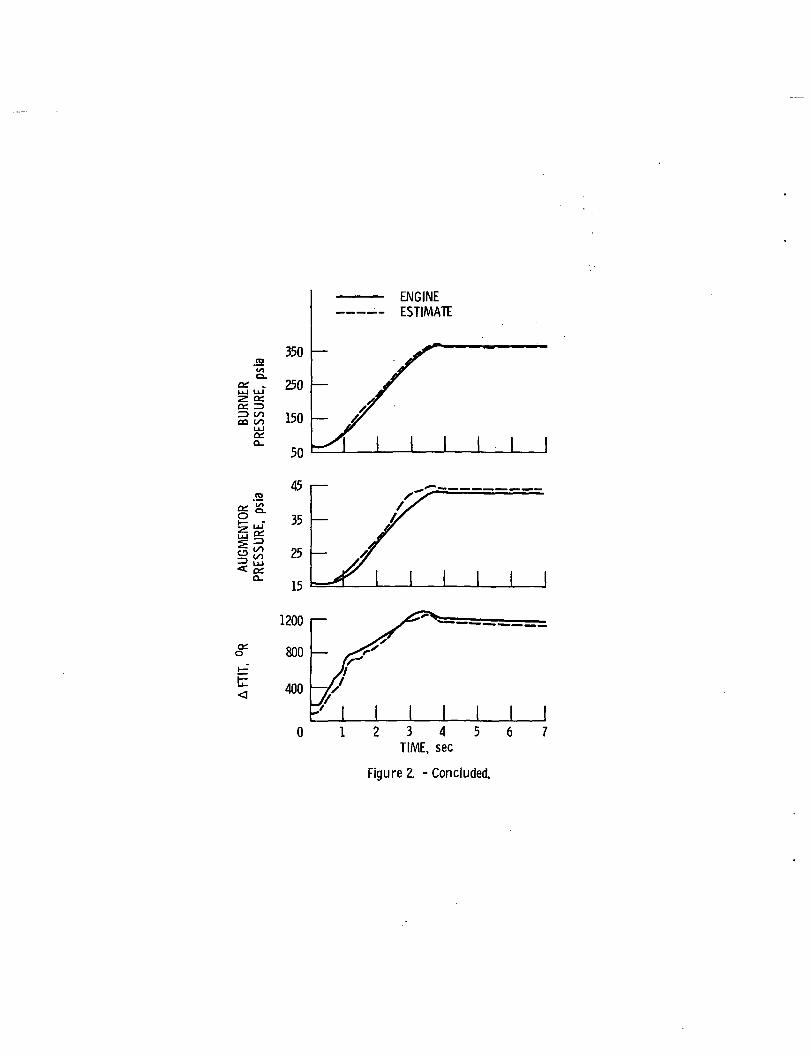
Individual elements of the state-space matrices were corrected to reduce datascatter and then scheduled by a nonlinear polynomial of selected model outputvariables over the flight envelope. This scheduled state-space system formsthe basis of the simplified simulation. A more complete description of thismodeling technology as applied to the development of a hypothetical turbofanengine simplified simulation (HYTESS) 1s given by Merrill, et al. (ref. 20).Figure 2 shows a transient response comparison for the nonlinear digital enginesimulation and the ADIA simplified simulation for an Idle power to Intermediatepower (PLA.= 20° to 83°) step command. This comparison demonstrates the ex-cellent estimation capability of the simplified simulation. The AOIA algorithmIncorporates this simulation and Kalman filter logic to further Improve theseestimates.
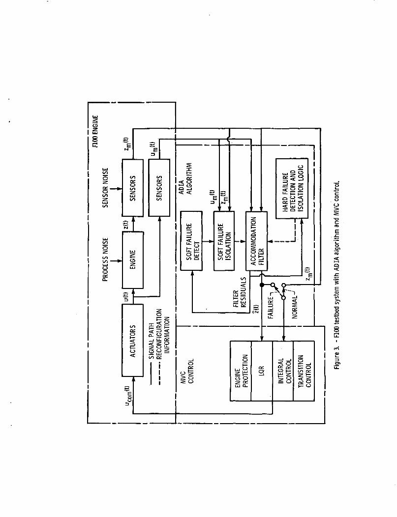
The testbed system with AOIA and NVC logic 1s shown 1n figure 3. Thealgorithm consists of an extended steady-state Kalman filter, called the accom-modation filter, that generates sensor estimates and residuals based upon asimplified, pseudo-linear model of the engine. These residuals are comparedto thresholds for hard failure detection and Isolation. A weighted sum of thesquared residuals (USSR) statistic Is computed and compared to a threshold todetect soft failures. When a soft failure 1s detected. Isolation Is accom-plished using a bank of five Kalman filters (one for each sensor) and likeli-hood ratio test of the five different filter residuals. After a failure Isdetected and Isolated, the faulty Information 1s removed from the accommodationfilter by reconfiguration. Estimates of all sensor outputs are still producedbut now they depend upon the set of unfa11ed measurements. The AOIA algorithmInterfaces with the NVC algorithm 1n two ways. First, 1t supplies the linear-quadratic regulator (LQR) with estimates of the engine outputs at all times.Second, 1t supplies the Integral control logic with actual sensed values 1nthe normal mode. An Individual sensed value Is only replaced with an estimatewhen a failure occurs and Is detected and Isolated.
Detailed evaluation results demonstrated the ability of the ADIA algorithmto completely cover hard sensor failures and most soft sensor failures. Thehard failure results were excellent. All failures were covered with nearlyInstantaneous detection and Isolation throughout the flight envelope. Accom-modation transients were well within allowable ranges. Steady-state perform-ance was good (see table III). On the other hand, soft failure DIA, especiallyfor a full envelope design, represents a substantially more difficult taskthan hard failure DIA. In spite of this challenge, soft failure DIA perform-ance was generally good. However, some soft failure modes remained uncovered.
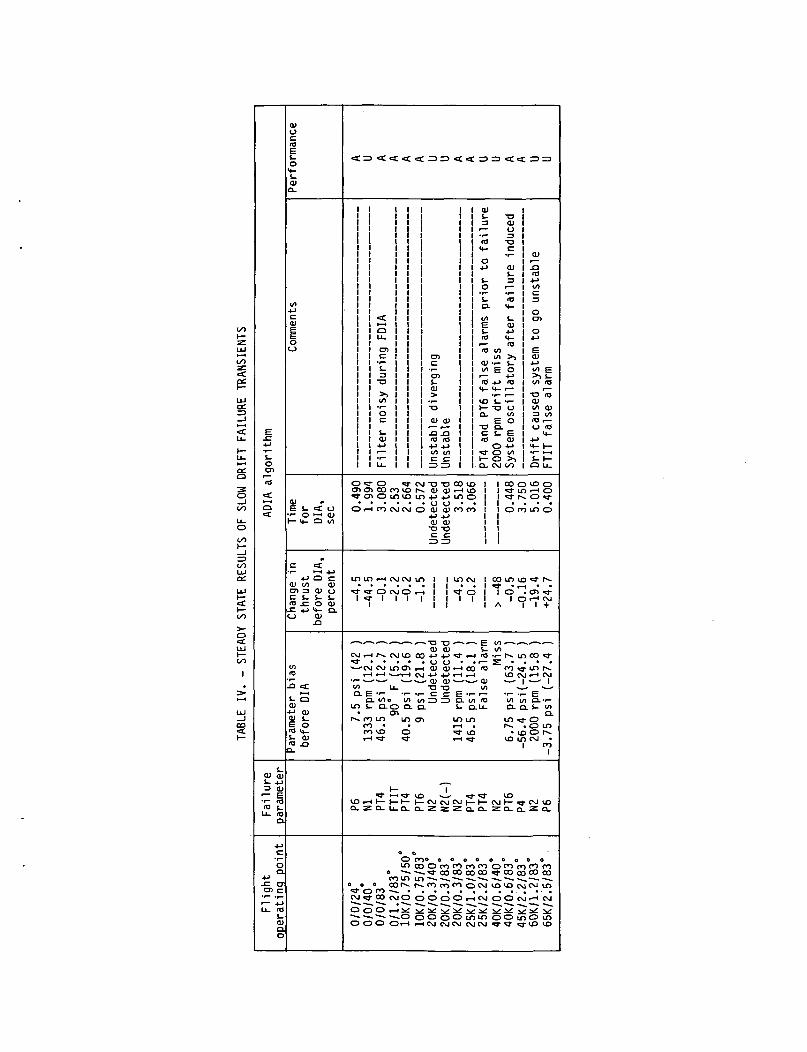
Table IV Is a summary of the evaluation of the soft failure DIA capabilityof the ADIA algorithm. Here data were obtained by Injecting slow drift fail-ures 1n various parameters at a variety of operating points throughout theenvelope. Sixteen failure scenarios are presented. The estimation error orbias before failure Isolation as well as the thrust change, and time to Isola-tion are given for each scenario. Nine of the presented scenarios representacceptable soft failure OIA performance. These scenarios Include PT4, PT6, andFTIT coverage over a large portion of the flight envelope with small thrustdeviations. One speed failure (N2) was also covered. Seven of the presentedscenarios represent unacceptable performance. Five of these are rotor speed(Nl or N2) failures. Because the filter estimation process 1s strongly depen-dent on Nl and N2 measurements (particularly N2) a slow bias error In the speedsignals will be tracked closely. Therefore the residuals will remain smalland will not Indicate a soft failure. As the filter 1s made less dependent on
rotor speeds, estimation accuracy decreases. This tradeoff requires more studyand will be one of the subjects Investigated 1n the real time hybrid evaluationphase.
The second part of the ADIA program 1s the real-time evaluation of thealgorithm on a hybrid computer FIDO engine simulation. A real-time micro-processor based Implementation of the MVC and ADIA algorithms Is required tocomplete this evaluation. DeLaat and Merrill (ref. 20) describe this Implemen-tation. Two 5 MHz Intel 8086 based microprocessors operating 1n a parallelprocessing environment are used to meet the update time requirement. The firstcomputer contains a fixed point, assembly language, real-time Implementationof the MVC which had been Implemented and evaluated previously (ref. 22). Thesecond computer contains the ADIA logic Implemented 1n floating point FORTRAN.Floating point arithmetic was used since the Intel 8087 floating point copro-cessor was available. FORTRAN was used because of the flexibility of program-ming 1n FORTRAN versus assembly language. Also, a good FORTRAN compiler forthe 8086/8087 was available. This control hardware Is currently being usedwith a hybrid computer engine simulation to evaluate the ADIA algorithm's real-time performance.
The third part of this program 1s the full scale engine demonstration ofthe ADIA algorithm. Current planning projects this evaluation to occur 1n thefirst quarter of 1985. The demonstration will take place 1n the NASA LewisResearch Center altitude test facility. The microprocessor hardware and soft-ware developed and evaluated 1n phase two of this program will be used 1n thisdemonstration.
E3 FICA
The E3 program 1s developing technology for Improving the energy effi-ciency of future commercial transport aircraft engines. A FADEC based uponthe bit-slice AMD 2901 microprocessor 1s used to Implement the control andFICA logic for the engine developed under this program (ref. 23). The FICAlogic Is based upon the concept of Spang and Corley (ref. 9). Here, a sixthorder extended Kalman filter 1s used to generate seven sensor estimates, fanand core speed, compressor Inlet and discharge temperatures, turbine dischargetemperature, fuel metering valve position, and compressor discharge staticpressure. The Kalman filter uses a dynamic model of simplified engine aero-thermodynamics and rotor dynamics. Actuator and sensor dynamic models arealso Included. This model accurately describes the engine over the full powerrange and flight envelope using simplified component modeling. The Kalmangain matrix 1s computed at a key operating point using a linearized enginemodel. Sensor failures are detected when the sensed versus estimated differ-ence 1s greater than a prespedfled tolerance. Out of range failures are alsodetected. The tolerance 1s estimated by statistical analysis and adjustedduring simulation trials. Accommodation of failures 1s accomplished by re-placement of sensed with estimated values. A nonlinear real-time simulationevaluation of the FICA logic showed that the filter estimate tracked the sensedvalues within the specified tolerance and successfully detected, Isolated, andaccommodated all hard sensor failures except fuel metering valve position.Multiple failures were also successfully handled. Tests with a reduced orderImplementation of the Kalman gain matrix that eliminated the three temperaturesensors showed successful DIA with all sensors except core speed and fuel
metering position. The E3 FICA logic does not detect slow drift. I.e., soft,sensor failures.
FADEC PICA
Under the FAOEC program (ref. 24), AR techniques (1n particular PICA)were applied to two engines, a Joint Technology Demonstrator Engine (JTDE) andto the F404 afterburning turbofan engine. Each of these applications 1s dis-cussed below.
The JTDE FICA was designed for a variable cycle engine with seven manipu-lated variables and nine sensed variables. The engine model used 1n the JTDEFICA 1s a second order, dynamic pseudo linear model valid throughout the flightenvelope. The model 1s updated by an observer. Observer gains were chosen asthe reciprocals of corresponding engine model steady-state gains at a highpower condition. Gains were then adjusted to achieve adequate stability mar-gins. For failure detection sensor model errors were compared to a presetthreshold. Substitution of estimated variables was demonstrated using a simu-lation and subsequently a full scale engine. The engine demonstration waslimited to sea level static conditions and single substitutions. Single sub-stitutions for fan speed, compressor discharge static pressure, and compressorInlet temperature were successfully performed. Also demonstrated by simulation1n this program was the application of FICA techniques to actuator sensor fail-ures. In particular, fuel flow and nozzle area actuator hard out-of-rangesensor failures were detected and accommodated.
The second application 1s the F404 FICA. The F404 1s an afterburningturbofan engine with a rear variable area bypass Injector (VABI) to permitselective cycle rematch. The VABI adjusts the bypass to core air ratio tomatch cycle demands. The engine Includes five Inputs and five outputs. Asimplified, fourth order, component level model (ref. 25) 1s used 1n the FICAsystem. The model 1s accurate throughout the flight envelope and was Imple-mented 1n FADEC microprocessor hardware 1n a 0.01 second update time Increment.The model along with the FICA update logic was checked against actual engineoperation during full scale engine tests at sea level static and altitude con-ditions from September 1981 to April 1982. Steady-state and transient modelaccuracies were judged to be excellent. Single, double, and triple substitu-tions of FICA generated estimates were successfully performed during the enginetests. These combinations are summarized 1n figure 4. Actuator FICA was alsosuccessfully demonstrated for exhaust nozzle hard open and closed failures.Thrust level In these cases was maintained by adjusting the gas generator speedreference schedule.
DEEC DIA
The DEEC system 1s a digital full-authority control system containingselectively redundant components and fault-detection logic. The system alsocontains a hydromechanlcal back-up control. Most of the sensors 1n the controlare hardware redundant. However, failures of the Inlet static pressure PS2,burner pressure, PB, and fan turbine Inlet pressure, FTIT, are covered using aform of AR called parameter synthesis (PS).
In PS an estimate of one measured variable 1s synthesized from an alge-braic function of one or more different measured variables. This relationship1s static, I.e., no explicit dynamics are Included. If PS2 falls a rangecheck, a synthesized PS2 1s determined from PB, compressor speed, N2, and Inlettotal temperature, TT2. IF PB falls, a synthesized PB 1s calculated from Inlettotal pressure, PT2, N2, and TT2. Fault detection of PB failures 1s basedupon a comparison of measured and synthesized values. A comparison toleranceof *. 25 percent determines failures. This large tolerance precludes detectionof soft failures. Both PS2 and PB failures are accommodated by substitution.
There are two groups of FTIT sensors. This allows hardware redundancy.However, 1f both FTIT sensor groups fall a range check, synthesized FTIT 1ssubstituted Into the control. Synthesized FTIT 1s a function of PB and PT2.
The OEEC DIA logic was verified by closed-loop bench testing. Simulatedsea level and altitude engine transients were performed. Faults were Inten-tionally produced to evaluate DIA effectiveness. Subsequent sea level andaltitude full scale engine tests uncovered no new problems with the DIA logic.A series of flight tests of an F15 aircraft with an FIDO engine and DEEC con-trol further demonstrated the DEEC Logic (ref. 26). During the flight pro-gram, the DEEC DIA logic did not detect any false alarms and did not cause anyreversions to backup hydromechanlcal control. Two sensor failures occurredduring the flight program. One, Inlet temperature, was covered by redundanthardware. The second, exhaust nozzle pressure, failed to a high scale sensorlimit. Appropriate accommodation action was taken by the logic 1n each case.
Neither of the two sensor failures encountered 1n the flight test programdemonstrated the AR based logic of the DEEC DIA. Additional flight tests areplanned for late 1984 which will Incorporate Intentional sensor faults to com-pletely evaluate the DIA logic.
AR Technology Assessment
From the above survey an assessment of the relative state-of-the-art ofapplied AR can be obtained. The results presented 1n the technology base, andsummarized l.n table I, demonstrate the feasibility of AR based DIA. In par-ticular straightforward range or rate checks have provided successful detectionof hard sensor failures. Further, advanced DIA approaches based upon advancedstatistical decision theory and optimal filtering have demonstrated soft fail-ure DIA feasibility. However, this soft failure DIA capability 1s obtained atthe cost of Increased computational complexity. This additional complexityconsists of two parts: the filtering and decision making logic, and a moreaccurate, and therefore more detailed, model. These results also demonstratea tradeoff between ability to accurately detect and time to detect. Wherehard failures can be detected almost Instantly, soft failures are reliablydetected only after some finite amount of time. This time to detect Is afunction of threshold level, which determines detection reliability, modelaccuracy, and logic complexity.
Further results presented 1n the technology development section demon-strate AR based DIA capability for hard sensor failures on full scale enginesover a limited range of power and flight conditions. Soft failure DIA hasbeen demonstrated throughout the flight and power envelope but only on a de-tailed nonlinear simulation of the engine. Full scale engine testing remains
10
to be done. A study of the results of this development clearly emphasizesthe fundamental Importance that modeling plays 1n successful OIA. A modeldetailed enough for accurate DIA throughout the flight envelope Is a signifi-cant technical challenge. Expectedly, when faced with a difficult technicalproblem, different approaches are pursued. Three different modeling approacheshave been used: 1) Parameter Synthesis (PS), 2) Pseudollnear (PL), and 3) Sim-plified Component (SC). Both PS and SC approach have been used In successfulhard failure DIA on full scale engines. The PL method has been demonstratedfor both hard and soft failure OIA using a detailed nonlinear simulation.Each approach has Its advantages and disadvantages.
The PS approach which was used 1n the OEEC OIA 1s simple to understandand straightforward to Implement. Explicit dynamics are normally not Included.However, this simplicity Implies a less accurate model. Also, the most accu-rate Interrelationships between measured and synthesized variables can not beeasily or systematically Identified. Model modifications are easily made.
The SC approach, which was used 1n the FADEC PICA, results 1n more accu-rate models than the PS approach. SC models are based upon detailed nonlinearengine simulations. Detail 1s selectively removed from the detailed simulationto maximize simplicity while maintaining accuracy. This process requires agreat deal of judgment and 1s not straightforward or systematic. Additionally,simplified model performance Is not easily predicted. An SC model relatesnaturally to the physics of the actual engine and 1s therefore readily under-standable. However, modification of an SC model 1s not straight forward sincechanges 1n component performance can unprechctably effect model performance.
The PL modeling approach which 1s used 1n the ADIA algorithm, 1s a veryorganized, systematic approach. However, to achieve accuracy through a widerange of conditions requires a large amount of stored data. The relationshipof a PL model with engine physics 1s not as straightforward as for an SC model.However, steady-state and dynamic model performance can be separated and modi-fied Independently. Due to the linear structure of the model equations, anal-ysis and performance prediction 1s much easier with a PL model than with PS orSC models. Additionally, the complexity-accuracy tradeoff 1s more clearlydefined for a PL model.
Current Programs
Currently four programs are underway to address technological needs 1n ARbased DIA. These programs are ADIA, Robust DIA (RDIA), Multiple Engine DIA(MEDIA), and Analytical Redundancy for Engine Reliability Improvement (ARTERI).
ADIA
As stated 1n the technology assessment, soft failure DIA has not beendemonstrated on a full scale engine. This 1s one of the main objectives of theADIA program. As such, 1t represents the first serious attempt at soft failureDIA. Also, this program represents the first full envelope design. Includingdesign, development, evaluation, and full scale engine demonstration. Toaccomplish this program, a real-time microprocessor based Implementation ofthe ADIA has been Implemented and 1s being evaluated on a real-time hybridengine simulation. This evaluation will establish an Important data point on
11
the tradeoff between detection time and reliability, as well as algorithm com-plexity and detection capability. A successful full scale engine demonstra-tion of hard and soft failure OIA will clearly establish AR based DIA as anaccepted tool to Improve engine control system reliability.
ROIA
NASA 1s currently pursuing basic research 1n Robust Detection, Isolation,and Accommodation (ROIA) of sensor failures. This research focuses on onefundamental question. How accurately must engine dynamics be modeled for suc-cessful DIA. A definitive answer to this question would establish the quanti-tative tradeoffs between complexity, detection time and detection performance.An alternative viewpoint would be to define the robustness of a DIA algorithmto model Inaccuracies or uncertainty. Two contractors, Alphatech, Inc. andSystems Control, Inc. have Identified two different approaches to the solutionof this problem.
Alphatech, Inc. bases their research on redundancy, or parity relations.These relationships among the measured system variables Incorporate all pos-sible redundant Information available. Modeling uncertainty affects the re-liability of these parity relations. For a quantified level of uncertainty,all parity relations can be ranked from most to least reliable. This allowsthe more reliable parity relations to be used to generate DIA strategies thatare as robust to uncertainty as possible.
Systems Control Technology (SCT) bases their research on recent advances1n robust control system design. Model uncertainty effects on DIA robustnesswill be quantified using conic sector uncertainty properties. Here uncertaintythat 1s bounded 1n a conic sector 1n the frequency domain and which then propa-gates through a system, remains bounded by a conic sector. These sectorsdetermine quantitatively the performance/robustness tradeoff. This frequencydomain description of uncertainty along with frequency shaped linear quadraticfilter design theory allow the DIA strategy to be designed 1n the frequencydomain. This frequency shaped filter will yield Innovations that are optimallyrobust to model uncertainty. Thus, sensor failure detection based upon theseInnovations will also be robust.
MEDIA
A current NASA program 1s Investigating a variation of hardware redundancyto Improve soft failure DIA capability. In this contracted feasibility study,General Electric Corp. examined a multlengine approach (1n this case twoengines) to soft failure DIA. The underlying principle 1s to use a like sensormeasurement from one engine as redundant Information to Improve DIA capabilityon another engine. This approach Incorporates a model of potential enginedifferences, an average engine model, and decision logic. By looking at thesum and differences of redundant sensed values for the two engines, measuredaverage and differential performance Is obtained. These are compared to theaverage and difference engine models contained 1n the DIA logic. This addi-tional Information allows Improved DIA performance over a single engine con-cept. This concept was demonstrated using a digital nonlinear enginesimulation.
12
ARTERI
The final program, ARTERI 1s sponsored by the US Navy. ARTERI started 1nOctober 1983 and Is a three year program. Its objectives are to develop ARtechniques based upon PICA to the point where they may be employed 1n a fullscale engine development program. Both hard and soft failures must be coveredover the full range of engine power and flight conditions. A detection filterapproach 1s proposed to extend PICA to Include a soft failure DIA capability.Also, to be Included 1s a thorough Investigation of the ability of the logicto discriminate among sensor, actuator, and engine failures. The results willbe evaluated on a full range nonlinear transient simulation. This simulationwill Include models for the extended PICA and PADEC control logic. The resultswill then be demonstrated on a full scale Joint Technology Demonstrator EngineIn 1986.
CONCLUDING REMARKS
The technology base for AR based sensor failure DIA strategies for gasturbine engines has been surveyed. Several observations and conclusions aremade. First the technology base often builds or expands upon technologydeveloped for aircraft controls. This 1s particularly true of hypothesis basedtechniques. However, less stringent reliability requirements and more adversesensor environments are pushing the engine controls designer to AR rather thanHR solutions to reliability requirements. Secondly, modeling 1s the key Issue1n the success or failure of AR techniques. Three types of models are used.Each has Its advantages and disadvantages and no clear preferred type emerges.Finally, simulation or full scale engine testing has conclusively shown thefeasibility of AR based DIA for hard failures. Soft failure DIA has beendemonstrated, so far, only by simulation. The results were very encouragingbut not totally successful. Work remains to be done 1n this area.
Three on"-go1ng Government sponsored programs that address soft failureDIA were summarized. One of these programs will supply a complete theoreticalunderstanding of robust DIA concepts. The second showed the feasibility ofmuIt1engine DIA concepts. The third will extend PICA technology to full scaleengine development. Finally, the ADIA program will be taken to a full scaleengine test to demonstrate a soft failure DIA capability.
REFERENCES
1. Baker, L. E., Warner, 0. E., and Dlsparte, C. P., "Design of FaultTolerant Electronic Engine Controls," AIAA Paper 81-1496, July 1981.
2. Wallhagen, R. E., and Arpasl, D. J., "Self-Teaching Digital-ComputerProgram for Pall-Operational Control of a Turbojet Engine 1n a Sea-LevelTest Stand," NASA TH X-3043, 1974.
3. Hrach, P. J., Arpasl, D. J., and Bruton, W. M., "Design and Evaluation ofa Sensor Pall-Operational Control System for a Digitally ControlledTurbofan Engine," NASA TH X-3260, 1975.
4. Ellis, S. H., "Self-Correcting Control for a Turbofan Engine," 3rdInternational Symposium on A1r Breathing Engines. Proceedings, WestGermany, March 7-12, 1976, pp. 171-186.
5. de S11va, C. W., "Sensor Failure Detection and Output Estimation forEngine Control Systems," M.S. Thesis, University of Cincinnati,Cincinnati, Oh., 1976.
13
6. de S1lva. C. W., "Real-Tine Failure Detection of Aircraft Engine OutputSensors', Arabian Journal for Science and Engineering. Vol. 7, No. 1.Jan. 1982, pp. 45-53.
7. Wells, W. R., and deSllva, C. W., "Failure State Detection of AircraftEngine Output Sensors," Proceedings of Joint Automatic Control Conference.San Francisco, CA, June 24. 1977, Vol. 2, pp. 1493-1497.
8. Wells, W. R., "Detection of Sensor Failure and Output Reconstruction forAircraft Engine Controls," AIAA Paper 78-4, 1978.
9. Spang, III, H. A. and Corley, R. C., "Failure Detection and Correctionfor Turbofan Engines," (AIChE. ASME. IEEE. ISA, and SHE. Joint AutomaticControl Conference. San Francisco, CA., June 22-24, 1977.
10. DeHoff, R. L., and Hall, Jr. W. E., "Advanced Fault Detection andIsolation Methods for Aircraft Turbine Engines," Systems Control, Inc.,ONR-CR-215-245-1, Feb. 1978.
11. Sahgal, R. K., and Miller, R. J., "Failure Accommodation 1n Gas TurbineEngines with Application Fan Turbine Inlet Temperature Reconstruction,"Proceedings of Joint Automatic Control Conference. Denver, CO, June 17-21,1979, pp. 381-386.
12. Le1n1nger, G. G., and Behbehanl, K., "Sensor/Actuator Failure Detectionand Isolation for Alrbreathlng Propulsion Systems," Proceedings of JointAutomatic Control Conference. San Francisco, CA, August 13-15, 1980, Vol.2, pp. TP4-B.
13. Behbehanl, K., "Sensor Failure and Mu1t1var1able Control for AlrbreathlngPropulsion Systems," University of Toledo, Toledo, Oh., Ph.D. Thesis,Mar. 1980. (NASA CR-159791).
14. Behbehanl, K., and Lelnlnger, G. G., "Sensor/Actuator Failure Detectionfor Turbofan Engines," Propulsion Controls. 1979. NASA CP-2137, 1980, pp.139-143.
15. Meserole, J. S., "Detection Filters for Fault Tolerant Control of TurbofanEngines," Ph.D. Thesis, Massachusetts Institute of Technology, 1981.
16. Lelnlnger, G. G., "Model Degradation Effects on Sensor Failure Detection,"Proceedings of Joint Automatic Control Conference. Charlottesvllle, VA,June 17-19, 1981, Vol. 2, FP-3A.
17. Seattle, E. C., LaPrad, R. F., McGlone, M. E., Rock, S. M., and Akhter,M. M., "Sensor Failure Detection System," Pratt and Whitney AircraftGroup, East Hartford, Conn., PWA 5736-17, Aug. 1981). (NASA CR-165515).
18. Seattle, E. C., LaPrad, R. F., Akhter, M. M., and Rock, S. M., "SensorFailure Detection for Jet Engines," Pratt and Whitney Aircraft Group,East Hartford, Conn., PWA-5891-18, May 1983. (NASA CR-168190).
19. Lehtlnen, B., Costakls, W. G., Soder, J. F., and Seldner, K., "F100Mult1var1able Control Synthesis Program - Results of Engine AltitudeTests," NASA TM S-83367, 1983.
20. Merrill, W. C., Seattle, E. C., LaPrad, R. F., Rock, S. M., and Akhter,M. M., "HYTESS: A Hypothetical Turbofan Engine Simplified Simulation,"NASA TM-83561, 1984.
21. Delaat, J. C., and Merrill, W. C., "A Real-Time Implementation of anAdvanced Sensor Failure Detection, Isolation, and AccommodationAlgorithm," NASA TM-83553, 1983.
22. DeLaat, J. C., and Soeder, J. F., "Evaluation of a MicroprocessorImplementation of the FIDO Hult1var1able Control. Proposed NASA TechnicalMemorandum.
23. Beltler, R. S., and Lavash, J. P., "Energy Efficient Engine (E3):Controls and Accessories Detail Design," General Electric Co., Cincinnati,Oh., R82AEB400, Dec. 1982. (NASA CR-168017).
14
24. Kreltlnger, T. M., Marvin. N. D., Hurtle, J. E.. LlnebHnk. K. L..Cornett, J. L.. Weber, D. P.. and Wright. W. E., "Full Authority DigitalElectronic Control, Phase II, Final Report - Industry Version," GeneralElectric Company, Cincinnati, Oh., R82AEB435, Oct. 1983.
25. French, N. W., "Development of a Compact Real-Time Turbofan Engine DynamicSimulation,1 SAE Paper 821401, Oct. 1982.
26. UnebMnk. K. L., and V1zz1n1, R. W., "Full Authority Digital ElectronicControl (FADEC) - Augmented Fighter Engine Demonstration," SAE Paper821371, Oct. 1982.
27. Myers, L. P., Mackall, K. 6., Burcham, Jr., F. W., and Walter, W. A.,•Flight Evaluation of a Digital Electronic Engine Control System In anF-15 Airplane," AIAA Paper 82-1080. June 1982.
15
3
m
oQJcra
QJOin
IE**-o «1- O
f in
QJ3 */t
C0
3
UJ
CS- QJ
"3 oCX J-
o >5
_
oQJCX
I—
4-O
QJCX
*~
QJO
*QJ•ao
QJCXraa.
04
o4Jram
QJ
raQJ
CO
OJ
3
II•+-• O
ra c
cc E
+iQJ
CXQJce
•o
ra
QJ
3
ra"•
t,ra3:
CO
°-
+jQJ
"»~t
St.34-*
in00"•3
rac a.OJ t-cn<
^- cra3
^
OICXraCX
ocoincOJ
XUJ
^~
4->
JZcn
cn •«-C i—t- VI l*_4-» C O)ra o jz exi- 4-> cn oOl -r- 3 •—
o"c ° >OJZ C
in o 4-> o)
OJ
3
It£ 0
ra c
a'i
+f
QJ
CXQJ
-oo
•1- v»> QJ
I-Vt JZQJ 4->t.3 4->
i»- • —
•O QJ
3: 1_
COa.
c0
124-> 3
ra inQJi- -oo *-
1— JZ
^_<n cra o1- 3
0 Cra ras_x
10
o
(O
VI
QJ
ra — iQJ CO
CO •— •
c
o
'ra ra
cn eO VI
"S "v> m o
4-* 4-> 0> QJ Olra in c 4-> cn-t-E >> o J= rat*-
VI i— >» QJ > Ouj ra.a:x ra E
^_
QJ i-JZ QJO >
ra•o.— -O QJ0 QJ 4->
JZ 4-> roin JZ EQJ cn-r-
jz QJ mt- s QJ_,Q.
•ocra
COo.
1- Oc ra •*-ra QJ •— 4-»i*. c as ra
"£ *C-*cnE3 o -.- -r-
i— c -o v)
in
^~
UJ
OJ
CO1
CO
c0
ra ra4-» r—
cn Ea in
OJco
C V)ra QJ
in 4->QJ O
CO JZ
4-> o i-•r- QJ5 J^ 4-»
i ra •»-Q_ -D 4-
OJ•o
QJ
ra oOJ J3c t-
0 M-z o
ra•o >c: i —
vti— QJ
QJ
***>
CO
V)
QJE
~32ra cn c
Q£ 13 U
co^33
3CO
inra
4- 3O "O
c m•o o OJo *«~J= fc. 1-in re QJQJ CL4->
t— O 4-
4-> c i-•i- ra QJS E 4->
<_> ra -f-CO ^ M-
•o
JZc
QJ 0
4J raLU i —UJ • — 3co <o ECJ OJ''-cr 4. m
•ac >»ra QJcn i_S3CX
CO
•o3
m^_rao
Olfc.
(—
i-H
1
CO
co
22•r- 3cn£Q </)
QJC
1
OoJZ
•—
E
Xraz:
(_jCO
ooCXVI 4->
Q)OJ ••->
•— oC J_•«- 3
ra
<*- •—o ra3; 3:QJO
^~
VICo
4-*
co
o2
t—
c
0
« (04-Jf—
cn E
o mco•M3
3CO
QJCo
1Q_
raQJc:
'c:-°o"^C (O
§1LL. V)
Cra u
QJ
ra f—
raCO
•o3
«
0
4^rao
CX
ra
•ocra,_ra
OJi_
SJZ1—
CD
CO1
CO
co
4-* I —
cn EO in
QJ
OZ
CD
_Ja.
raQJc
c oo *»~
UJ •—
Or V>
•ocra —c:
S.SQJ_J
3
Vt
Co4Jrao
CX
ra-ocra
^o
QJ
OOf
1—
in
CO
CO
co
*£cn E
O in
QJcOz
QJ
Co
oQJ
O
Ia.
i.raQJct- C•— oc •*-04->
c ra
O 3o E.-t •»-U_ in
QJ
oQJinQJE;
QJ•oi
^A C
•O
QJ
h- 3
ro
CO1
CO
co
ra ra•*- 3cnEO V)
QJco
inOJ
s
=
l_raOJci
co
ra3Ein
UJ
c*
l_a>cnc:
cQJ
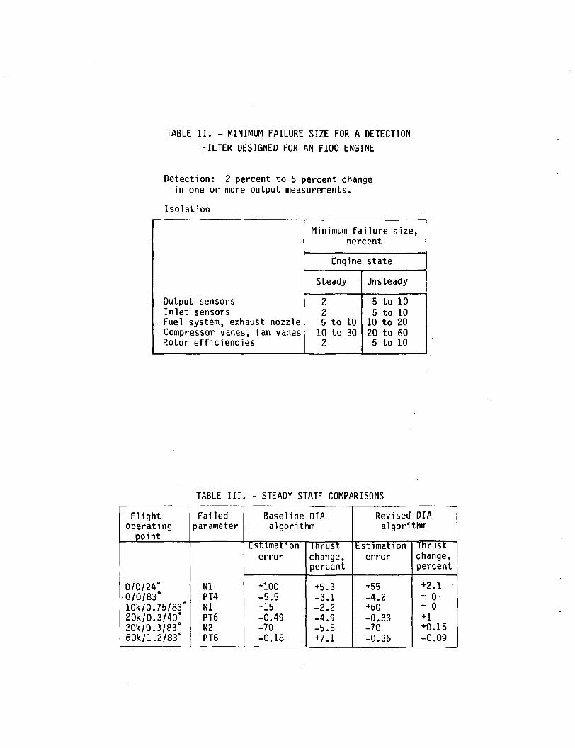
TABLE II. - MINIMUM FAILURE SIZE FOR A DETECTION
FILTER DESIGNED FOR AN F100 ENGINE
Detection: 2 percent to 5 percent changein one or more output measurements.
Isolation
Output sensorsInlet sensorsFuel system, exhaust nozzleCompressor vanes, fan vanesRotor efficiencies
Minimum failure size,percent
Engine state
Steady
225 to 1010 to 302
Unsteady
5 to 105 to 1010 to 2020 to 605 to 10
TABLE III. - STEADY STATE COMPARISONS
Flightoperating
point
0/0/24°0/0/83°10k/0. 75/83°20k/0.3/40°20k/0.3/83°60k/1.2/83°
Failedparameter
NlPT4NlPT6N2PT6
Baseline DIAalgorithm
Estimationerror
+100-5.5+15-0.49-70-0.18
Thrustchange,percent
+5.3-3.1-2.2-4.9-5.5+7.1
Revised DIAalgorithm
Estimationerror
+55-4.2+60-0.33-70-0.36
Thrustchange,percent
+2.1~ 0~ 0+1+0.15-0.09
COIUJ
oCO
UJI—CO
EJZ4->
i-oenIO
0
s_at cuI- 4->3 CD
^ E
U_ IOQ
C
o
§gr— | *u- ia
s_cuoo
cuucIO
Eoi.0)o_
004JcCO
c_>
E i- «aTu•r- o •-" CU1 — it- O 00
c <•r- KH 4_3
4J Q CCU l/> CUen 3 cu oc t. s- s-10 jc o <uJ= 4-> M- O.0 CU
JO
0010-D «^
i— ti. 0(U
4-> Qlnj «
1 °i- CU(O joQ-
«««==«««= =
^C
Ou.enc
3•o
>^(/)•t—ocs_
t <u1 4-11 -r-
1 1 u_
o^- o
o>cC7^
QJ>
•r~•o<L) OJ
»— r— •J3 J3IO IO
00 oOC C
(Us- -o3 CU
i— 0•r- 310 -a"*" .o4J CU
s-O r-
S- 10o. >*-00 i.£ Oi- 4->IO o_F- iaIO OO
00 >,0) T- i.
tfi E OI— 4->IO 4-> IO
v»- l*_ i —•^ ^~
ID 1- •!-
>— T3 (JQ. 00
E 0•a o.c s_ EIO CU
O 4->^* o oo1- 0 >>Q. OJ CO
cu^~f>IO
00
3
oenoi *
ECU
oo E>> S-
,__
•a 10cuOO QJ3 00IO r—U >O
>*-
*4— 1 —•I— t— 1S- 1—a u.
^roj-a-oooio I COOIDO^ ID 1^ CU CU »~l VD 1 ^ U"> ' — ' O} VD IT) 4-> 4-> U^ O 1 *sl" r^ O <3"
O i - H C O C M C O O d J Q J O O O O 1 OfOLOO
co cuc c
j
11
in to «-H CM CM ir> I ir> CM j co tr> ID <»• r*-^- «* o oo o .— t i <;
. ^^cu i— i r^ c>
^«^~^ *-
JVD a• 'CM OJ LOCTl r-
»— t »-H ^
oo uo. E ••-
Q. OOoLO fc. O.C
• Oi n ir>
f) •OO U3T-H f
1-•3- >-
Cl. Z G- U
'r-\ 0.
V) u:> a. c•
CO CUJ 4-> 4-> <
H CU CU <-J 4-> 4-> 1-
"O *O- c c E0 13 Z3 CX S.
• • 1 ^3^ • r—t O 1 O
I I 1 C1 A
•^^
t 1-i. in
•1 " •
^^^,^ CO «3-
4 CO IO CO «?!• LT> rH t-^«^
X 0. c
H ID O
OO -
0 (O (/) Lxu_ ex c
m CT> tn LT> to <o
* *3~ \£
•a•—
1
r i** ^
a- t— I— CSJ CM CXJ K
VD U
• q~ VD
J i— 1 OJ• — 1
? En O.-I—i S- oo
a.
;is1 CSJ •
CO
- t— OJ h— st CVJ VD. Q- za. a. z a.
0 0
0 . 0 CC«d- o co OJ - CO <\
)p^ r^rooocoocgiovocsjcvJLOJO O O O O i-•ic\) o o c\j-— i oj
-•>• — o oOoOuDto oOinOm* » ^3 co ^DI i-H oj c\j oj c\j oj ^r *^ ^r VD ID
«"»
ooe.
o
16
14
12
10
8
6
4
2
MILITARY—D— COMMERCIAL
LPW5000VPW2037
1950 1960 1970 1980YEAR
1990 2000
Figure 1. - Trends in control complexity of aircraft turbineengines.
UJQ_to
Q_ UJ
11000
9000
7000
5000
3000
13000
12000
11000
10000
9000
- ENGINE-- ESTIMATE
I I I I I
I I I I I1 2 3 4 5 6 7
TIME, sec
Figure 2. - Transient response comparison ofnonlinear digital simulation (engine) and theADIA simplified simulation (estimate). Flightconditions: altitude, Oft ; Mach number, 0;power lever angle, 20° to 83° at 0.2 sec.
Z OSD± =3ZJ COCO CO
UJ
O£.O
OIL
O COCO
o;o
t=t
350
250
150
50
45
35
25
15
1200
800
400
0
ENGINE._ ESTIMATE
2 3 4 5TIME, sec
Figure 2. - Concluded.
LUz0
1 iu
J-H
LUCO
0
O *"CO
LUCO
LUCO
O
COCO >LUoO
a.
1
ISl
(/Q
(/
U(/
e'
u2tlZu
* '
3
Q
1-
<
R
T*5•>•ji
'
j^
39
J
t
*»
3
3c
••>
—=F
</QCu
u</
i
C1-
S-**• ^0- S:_l LI
iiLD *-— Ut/1 Q
1
•>>iji
v
3
- 1—3 <
: fP: o
j
z
si"3
LUQ£
O LUCO Q
j L
O
S S
~
Lt
L
t
C
%
UJ£
|i'S*- F^§
(Lt
1
cr
^C^ ^)
^ if4- o:
z
ioLLJ Q
*5
>j3,*
i \
3—
aO
IE< n
^
s
i
ac
x
J
J
^^
£
I
f\\j
rLUa;_ j
2:
HARD
FAI
LURE
DETE
CTIO
N AN
DIS
OLA
TIO
N L
OGIC
i
_|
Nl
^ 9Nn
T <
\ '
—^ _l ^5
OH 01 tOOh- co a;t! Z Z >—to < Z2 0 ^ O
E= 0
o&_coo0
ST3Cn>
£
O
75
O
_£.
'i
t/)
"S
g
(U
.21
1
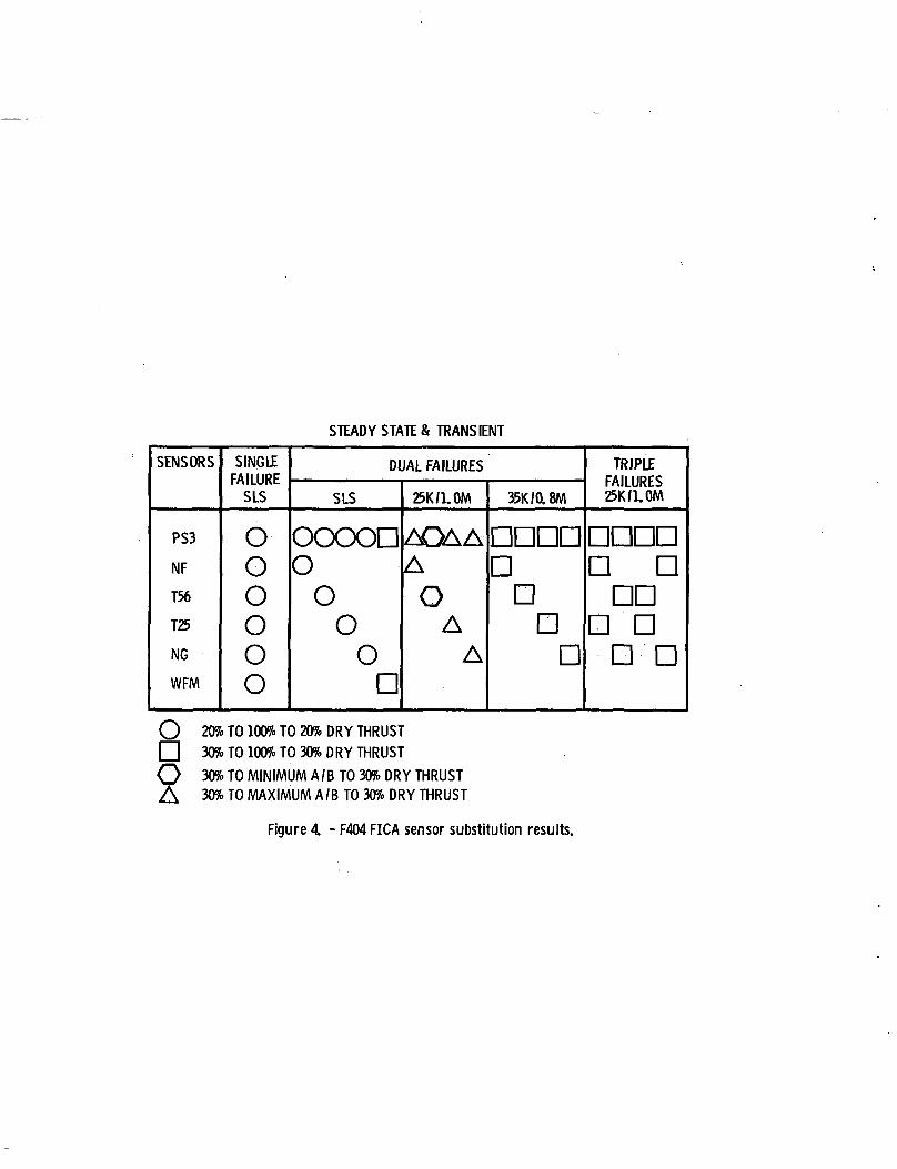
STEADY STATES TRANSIENT
SENSORS
PS3
NF
T56
T25
NG
WFM
SINGLEFAILURE
SLS
O
0
0
O
OO
DUAL FAILURES
SLS
OOOOD0
OO
On
25K/1.0M
AOAAA
OA
A
35K/0.8M
nnnnnnnn
TRIPLEFAILURES25K/LOM
nnnnn n
DDn nn n
O
§20% TO 100% TO 20% DRY THRUST
30% TO 100% TO 30% DRY THRUST
30% TO MINIMUM A/B TO 30% DRY THRUST30% TO MAXIMUM A/B TO 30% DRY THRUST
Figure 4 - F404 FICA sensor substitution results.
TM_83695
AIAA-84-1452
2. Government Accession No. 3. Recipient's Catalog No.
4. Title and Subtitle 5. Report Date
Sensor Failure Detection for Jet Engines UsingAnalytical Redundancy 6. Performing Organization Coda
505-32-6B7. Authors)
Walter C. Merrill
a Performing Organization Report No.
E-2123
10. Work Unit No.
9. Performing Organization Name and Address
National Aeronautics and Space AdministrationLewis Research CenterCleveland, Ohio 44135
11. Contract or Grant No.
12. Sponsoring Agency Name and Address
13. Type of Report and Period Covered
Technical Memorandum
National Aeronautics and Space AdministrationWashington, D.C. 20546
14. Sponsoring Agency Code
15. Supplementary Notes
Prepared for the Twentieth Joint Propulsion Conference cosponsored by the AIAA,SAE, and ASME, Cincinnati, Ohio, June 11-13, 1984.
16. Abstract
Analytically redundant sensor failure detection, isolation and accommodationtechniques for gas turbine engines are surveyed. Both the theoretical technologybase and demonstrated concepts are discussed. Also included is a discussion ofcurrent technology needs and ongoing Government sponsored programs to meet thoseneeds.
17. Key Words (Suggested by Authors))
Gas turbines; Sensor failures; Detection;Isolation; Accommodation; Analyticalredundancy; Survey
18. Distribution Statement
Unclassified - unlimitedSTAR Category 07
19. Security Classif. (of this report)
Unclassified20. Security Classif. (of this page)
Unclassified21. No. of pages 22. Price'
*For sale by the National Technical Information Service, Springfield, Virginia 22161
National Aeronautics andSpace Administration
Washington. D.C.20546
Official Business
Penalty for Private Use. $300
SPECIAL FOURTH CLASS MAILBOOK
Postage and Fees PaidNational Aeronautics andSpace AdministrationNASA-451
NASA POSTMASTER: If Undelrverahle (Section 1 5*Postal Manual) l>> Nut Return