Sensor-Equipped Cutting Tools to Visualize the Cutting Process
7
SUMITOMO ELECTRIC TECHNICAL REVIEW · NUMBER 92 · APRIL 2021 · 27 FEATURED TOPIC 1. Introduction Industrial digitization began with the German Industrie 4.0* 1 . In the machining sector, this trend is toward developing a system that maintains equipment and parts and monitors the production process, by mounting various sensors and communications equipment on machine tools and their peripheral devices and by acquiring and analyzing data. In Japan, the Internet of Things (IoT) and digitization are advancing as Society 5.0* 2 . Presently, automated and unmanned machining is promoted as digital transformation (DX* 3 ). Moreover, in the recent Covid-19-related confu- sion, people are having difficulties in traveling. New needs are arising, such as remote monitoring of machining and recording of machining processes. Cutting tools are positioned closest to the point of cutting. It has been considered that mounting sensors on a cutting tool would enable the machining process to be monitored with high accuracy. Accordingly, various research has been conducted on this. (1),(2) However, little of this research has led to commercialization due to the size and cost of sensors and wireless communication devices. Therefore, the aforementioned digitization trend has spread only in the field of machine tools and their peripherals. In recent years, however, research on mounting sensors on a cutting tool has been revitalized along with the sophistica- tion, miniaturization, and cost reduction of sensors. (3)-(6) Against this backdrop, Sumitomo Electric Industries, Ltd. conducts research and development of cutting tools on which sensors are mounted. This paper reports on the potential of sensor-equipped cutting tools for the moni- toring of cutting and the detection of faulty conditions. 2. Machining Digitization Trend Figure 1 shows a machining center as an example to outline a system that monitors and controls machining processes. A common method of monitoring wear of and damage to a cutting tool has been to measure changes in the electric current of the spindle motor that directly rotates the tool. More specifically, technological developments include determining tool life when the spindle current exceeds a certain threshold (7) and detecting faulty condi- tions by analyzing the spindle current by means of machine learning. (8) Other ongoing technological developments are the monitoring of the machining process based on the changes in the electric current of the servo motor used to drive the machine tool (9) and the monitoring of the machining process based on changes in measurements obtained from a strain or vibration sensor mounted on the machine tool. (10) Furthermore, a system that integrates these pieces of infor- mation and monitors the machining tool (11) and, at a higher level, integrated control systems capable of monitoring plant equipment on a global scale through machine tools (12) have also been developed. Additionally, with machining centers, mounting sensors on a tool holder that connects a machining tool to a cutting tool (13) has been put into prac- tical use. These arrangements of mounting sensors on a machine tool or its peripheral devices are highly versatile because the arrangement does not depend on the type of the cutting tool. However, placing sensors away from the point of cutting often fails to meet user requirements for abnormality detection due to low sensitivity to the cutting phenomenon occurring at the point of cutting. Specifically, using the electric current of the spindle motor, it is very difficult to monitor the machining process or detect faulty Sensor-Equipped Cutting Tools to Visualize the Cutting Process Yusuke KOIKE*, Tomoya AOKI, and Daisuke MURAKAMI ---------------------------------------------------------------------------------------------------------------------------------------------------------------------------------------------------------------------------------------------------------- The progress of digitalization increases the need for automated and unmanned cutting process. Sensor-equipped cutting tools are expected to be one of the measuring instruments that help visualize and monitor cutting operations because they are positioned closer to the cutting point than conventional measuring instruments, enabling more precise measurement. Sumitomo Electric Industries, Ltd. has promoted research and development on turning tools and milling tools that are equipped with sensors, wireless communication devices, and electric power sources. This paper presents feasibility studies on the monitoring of cutting operations with our sensor-equipped turning tool and milling tool. ---------------------------------------------------------------------------------------------------------------------------------------------------------------------------------------------------------------------------------------------------------- Keywords: cutting tool, sensor, Internet of Things (IoT) Tool holder Cutting tool Strain (deformation) Acceleration (Vibration) Temperature Machine tool, table, and workpiece Servo current Spindle current Table Workpiece Point of cutting Strain (deformation) Acceleration (vibration) AE wave temperature Servo motor Integrated control system Plant Plant Machine tools Data analysis, Control, Acquisition, records Machining center Spindle motor Fig. 1. Monitoring and control system for machining process
Transcript of Sensor-Equipped Cutting Tools to Visualize the Cutting Process

SUMITOMO ELECTRIC TECHNICAL REVIEW · NUMBER 92 · APRIL 2021 · 27
FEATURED TOPIC
1. Introduction
Industrial digitization began with the German Industrie 4.0*1. In the machining sector, this trend is toward developing a system that maintains equipment and parts and monitors the production process, by mounting various sensors and communications equipment on machine tools and their peripheral devices and by acquiring and analyzing data. In Japan, the Internet of Things (IoT) and digitization are advancing as Society 5.0*2. Presently, automated and unmanned machining is promoted as digital transformation (DX*3). Moreover, in the recent Covid-19-related confu-sion, people are having difficulties in traveling. New needs are arising, such as remote monitoring of machining and recording of machining processes.
Cutting tools are positioned closest to the point of cutting. It has been considered that mounting sensors on a cutting tool would enable the machining process to be monitored with high accuracy. Accordingly, various research has been conducted on this.(1),(2) However, little of this research has led to commercialization due to the size and cost of sensors and wireless communication devices. Therefore, the aforementioned digitization trend has spread only in the field of machine tools and their peripherals. In recent years, however, research on mounting sensors on a cutting tool has been revitalized along with the sophistica-tion, miniaturization, and cost reduction of sensors.(3)-(6)
Against this backdrop, Sumitomo Electric Industries, Ltd. conducts research and development of cutting tools on which sensors are mounted. This paper reports on the potential of sensor-equipped cutting tools for the moni-toring of cutting and the detection of faulty conditions.
2. Machining Digitization Trend
Figure 1 shows a machining center as an example to outline a system that monitors and controls machining processes. A common method of monitoring wear of and damage to a cutting tool has been to measure changes in the electric current of the spindle motor that directly rotates the tool. More specifically, technological developments
include determining tool life when the spindle current exceeds a certain threshold(7) and detecting faulty condi-tions by analyzing the spindle current by means of machine learning.(8)
Other ongoing technological developments are the monitoring of the machining process based on the changes in the electric current of the servo motor used to drive the machine tool(9) and the monitoring of the machining process based on changes in measurements obtained from a strain or vibration sensor mounted on the machine tool.(10)
Furthermore, a system that integrates these pieces of infor-mation and monitors the machining tool(11) and, at a higher level, integrated control systems capable of monitoring plant equipment on a global scale through machine tools(12)
have also been developed. Additionally, with machining centers, mounting sensors on a tool holder that connects a machining tool to a cutting tool(13) has been put into prac-tical use. These arrangements of mounting sensors on a machine tool or its peripheral devices are highly versatile because the arrangement does not depend on the type of the cutting tool. However, placing sensors away from the point of cutting often fails to meet user requirements for abnormality detection due to low sensitivity to the cutting phenomenon occurring at the point of cutting. Specifically, using the electric current of the spindle motor, it is very difficult to monitor the machining process or detect faulty
Sensor-Equipped Cutting Tools to Visualize the Cutting Process
Yusuke KOIKE*, Tomoya AOKI, and Daisuke MURAKAMI
----------------------------------------------------------------------------------------------------------------------------------------------------------------------------------------------------------------------------------------------------------The progress of digitalization increases the need for automated and unmanned cutting process. Sensor-equipped cutting tools are expected to be one of the measuring instruments that help visualize and monitor cutting operations because they are positioned closer to the cutting point than conventional measuring instruments, enabling more precise measurement. Sumitomo Electric Industries, Ltd. has promoted research and development on turning tools and milling tools that are equipped with sensors, wireless communication devices, and electric power sources. This paper presents feasibility studies on the monitoring of cutting operations with our sensor-equipped turning tool and milling tool.----------------------------------------------------------------------------------------------------------------------------------------------------------------------------------------------------------------------------------------------------------Keywords: cutting tool, sensor, Internet of Things (IoT)
Tool holder
Cutting tool
Strain(deformation)Acceleration(Vibration)Temperature
Machine tool, table,and workpiece
Servo current
Spindle current
TableWorkpiece
Point of cutting
Strain(deformation)Acceleration(vibration)AE wavetemperatureServo
motor
Integrated control system
Plant Plant
Machine tools
Data analysis, Control, Acquisition, records
Machining center
Spindlemotor
Fig. 1. Monitoring and control system for machining process

28 · Sensor-Equipped Cutting Tools to Visualize the Cutting Process
conditions during turning that involves workpiece rotation. The reason is that the power required to rotate the work-piece is higher than the power used to overcome the cutting resistance produced at the point of cutting. Thus, expecta-tions are high for the mounting of sensors on a cutting tool that is closest to the point of cutting, which enables the machining process to be monitored with high accuracy and sensitivity, albeit declining versatility.
Figure 2 presents a common breakdown of cutting costs including tool and personnel expenses. It is generally said that the proportion of cutting tool costs to cutting costs is approximately 4%, although this differs between indus-trial sectors and individual users, while personnel costs account for approximately 34%.(14) Moreover, in actual machining, it is likely that production loss is incurred at a proportion of between 5% and 10%. The causes include discarded defective parts, screening of defective parts, minor machine shutdowns following machining faults, and lowering of processing efficiency intended to avoid defects. Use of sensor-equipped cutting tools would certainly enable the reduction of tool costs owing to extended tool life. However, in view of the overall costs of the cutting process, the effect of tool cost reduction is small. Consequently, if only tool cost reduction is considered, the deployment of sensor-equipped cutting tools is not very cost-effective. Therefore, it is important to take note of other factors: personnel cost cutting through automation, production loss reduction by monitoring the machining process, and machining with high efficiency within a small amount of time while avoiding faulty conditions to reduce personnel expenses and depreciation on equipment. Furthermore, both the size of the working age population and the number of skilled workers are expected to decrease in the future. Given this factor, it is highly probable that the role of sensor-equipped cutting tools will become impor-tant from other perspectives such as quantitative evaluation of cutting.
3. Sensor-Equipped Cutting Tools Applied to Turning
Figure 3 illustrates a sensor-equipped turning tool for outside-diameter machining. A strain sensor is mounted close to the edge. A wireless communication device and a power supply are mounted close to the shank’s rear end.
The strain sensor measures strain on the body and outputs a value proportional to the cutting resistance. Measurements are transmitted from the sensor-equipped turning tool by radio and collected on a personal computer (PC) connected to a receiver. The sampling frequency is 2 kHz. The receiver is capable of establishing communication off the machine tool and can be installed on a window of the machine tool. This sensor-equipped turning tool, with all required compo-nents embedded in its body, offers the feature that it can be mounted directly on the tool rest of a lathe and does not interfere with the workpiece. Accordingly, it enables measurements with ease while cutting an actual part on an actual machine currently in use. Usage examples of a sensor-equipped turning tool are described below.
A cutting experiment involving interrupted cutting was conducted using a sensor-equipped turning tool to detect edge fracture. Figure 4 and Table 1 show the workpiece
Personnel34%
Equipment28%
Cutting tools4%
Materials15%
Other19%
Production loss
- Disposal ofdefective parts
- Screening- Machine shutdown- Lowering of
machining efficiency
5%-10%
+
Fig. 2. Breakdown of cutting cost
PC
Receiver
Power supply
Sensing capabilityWireless transmission capability
Wirelesscommunication
Fig. 3. Sensor-equipped turning tool
Direction of tool feed
Direction ofrotation
Fig. 4. Workpiece used in the interrupted cutting test
Table 1. Machining conditions
Cutting tool DCLNL2525M12
Indexable insert CNGA120412(BNC300)
Workpiece material Hardened steel
Cutting speed 100 m/min
Depth of cut 0.2 mm
Feed per revolution 0.1 mm/rev
Cutting fluid Dry

SUMITOMO ELECTRIC TECHNICAL REVIEW · NUMBER 92 · APRIL 2021 · 29
geometry and machining conditions, respectively. Figure 5presents the measurement results obtained before and after the occurrence of fracture. Figure 5 (a) provides strain features converted from strain measurements obtained before fracture occurrence. Since interrupted cutting was measured, waveforms representing repeated cutting and non-cutting sections were observed, as shown in Fig. 5 (b). With no frac-ture on the edge, the strain feature was constant within cutting sections. After fracture occurred, a discontinuous change was observed, as illustrated in Fig. 5 (c). Figure 5 (d)presents a photo of the tool edge after fracture. On actual shop floors, fracture is sometimes discovered by a change in cutting noise. However, when fracture similarly sized to that in Fig. 5 occurs, the operator in many cases fails to discover it because the change in cutting noise is minor compared with the operating noise of the cutting equipment. Use of a sensor-equipped turning tool enables minimal changes to tool edge to be captured.
Figure 6 provides an example of using a sensor-equipped turning tool to machine actual parts. First, the end face was machined, followed by inside diameter, corner, and end face machining. During the corner machining, the strain feature increased momentarily to about three-fold the previous level. Although increasing cutting resistance at a corner is generally assumed when setting a tool path and machining conditions, temporary increases to this level are beyond operators’ expectations. The measurement results obtained with the sensor-equipped turning tool led to this finding. By using sensor-equipped cutting tools to visualize machining, it is possible to discover unfavorable machining processes, as described above, and to provide an opportu-nity for reviewing machining conditions.
It is preferable in many cases to acquire a moderate amount of data, although in some cases new findings are obtained from a set of measurement results, as described in this article. The reason is that, in a process using a sensor-
equipped cutting tool, defective products are frequently produced by edge wear and geometrical variation in work-pieces. Therefore, it is important to acquire data sets over a modest period length, sufficiently containing changes and variations that resulted in defective products. By analyzing these sets of data in detail, it is highly likely that the causes of defective products can be identified and new findings can be obtained.
4. Sensor-Equipped Cutting Tools Applied to Milling
We have also evaluated the performance of milling tools, mounting sensors, a wireless communication device, and a power supply. Sumitomo Electric’s sensor-equipped milling tools have the following features.
First, measurements can be obtained in a rotating coordinate system rotating with the cutting tool. For multi-edged tools, measurement results can be separated with respect to each edge.
Second, measurement results are relatively immune to influences other than the cutting phenomenon, because the sensor is close to the point of cutting. Even with the use of a tool holder long in overall length, sensors can be installed closer to the point of cutting than in the instances of installing sensors at the base of a tool holder or on the main spindle. Moreover, the edges and the sensors can be set to constant relative positions in terms not only of distance, but also of phase around the milling tool’s axis of rotation.
Third, two types of sensors, strain and acceleration, are mounted to take measurements simultaneously. Strain and acceleration are physical quantities both arising from cutting resistance; however, different factors are involved in their occurrence. Strain sensor measurement results are strongly related to cutting resistance because they are
Time (second) Time (second)
Stra
infe
atur
e
Stra
infe
atur
eSt
rain
feat
ure
200 µm
Cutting section
Non-cutting section
Guide for fracture determination
Presumed zone ofchipping occurrence Fracture
Edge
Flank face
Flank wear
Time (second)
(a) Strain measurement results beforefracture
(b) Strain measurement results beforechipping for the 0.0 s-0.1 s duration, enlarged
(c) Strain measurement results at thetime of fracture
(d) Photo of edge after fracture
Fig. 5. Measurement results obtained before and after fracture
Str
ain
feat
ure
Side/corner/end faceEnd face
Quarter model showinga cross section of workpiece
Direction of rotation
Time (second)
Increasing loaddue to corner machining
Fig. 6. Strain measurement results for actual part machining
30 · Sensor-Equipped Cutting Tools to Visualize the Cutting Process
determined by the cutting resistance at the point of cutting and the rigidity of the milling tool. In contrast, acceleration sensor measurement results are strongly related to unusual vibrations and machining accuracy, because they are affected by the rigidity of the main spindle system comprising the main spindle and tool holder, as well as the rigidity of the discrete milling tool.
In view of the above-described features, we conclude that simultaneous measurements of strain and acceleration in the rotating coordinate system of a cutting tool produce useful data for optimizing cutting and clarifying cutting phenomena.
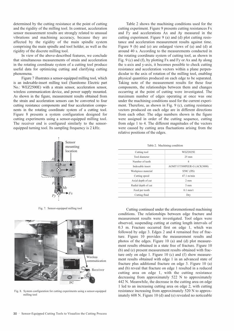
Figure 7 illustrates a sensor-equipped milling tool, which is an indexable-insert milling tool (Sumitomo Electric part No.: WEZ2500E) with a strain sensor, acceleration sensor, wireless communication device, and power supply mounted. As shown in the figure, measurement results obtained from the strain and acceleration sensors can be converted to four cutting resistance components and four acceleration compo-nents in the rotating coordinate system of a cutting tool. Figure 8 presents a system configuration designed for cutting experiments using a sensor-equipped milling tool. The receiver end is configured similarly to the sensor-equipped turning tool. Its sampling frequency is 2 kHz.
Table 2 shows the machining conditions used for the cutting experiment. Figure 9 presents cutting resistances Fx and Fy and accelerations Ax and Ay measured in the cutting experiment. Figure 9 (a) and (d) plot cutting resis-tance and acceleration measurement results against time. Figure 9 (b) and (e) are enlarged views of (a) and (d) at around 40 s. According to the measurements conducted in the rotating coordinate system of cutting tool, as shown in Fig. 9 (c) and (f), by plotting Fx and Fy or Ax and Ay along the x-axis and y-axis, it becomes possible to check cutting resistance and acceleration vectors within a plane perpen-dicular to the axis of rotation of the milling tool, enabling physical quantities produced on each edge to be separated. Taking note of the measurement results for these four components, the relationships between them and changes occurring at the point of cutting were investigated. The maximum number of edges operating at once was one under the machining conditions used for the current experi-ment. Therefore, as shown in Fig. 9 (c), cutting resistance vectors produced on each edge are in different directions from each other. The edge numbers shown in the figure were assigned in order of the cutting sequence, cutting from edge 1 to 4. The different magnitudes of the vectors were caused by cutting area fluctuations arising from the relative positions of the edges.
Cutting continued under the aforementioned machining conditions. The relationships between edge fracture and measurement results were investigated. Tool edges were observed, suspending cutting at cutting length intervals of 0.3 m. Fracture occurred first on edge 1, which was followed by edge 3. Edges 2 and 4 remained free of frac-ture. Figure 10 provides the measurement results and photos of the edges. Figure 10 (a) and (d) plot measure-ment results obtained in a state free of fracture. Figure 10 (b) and (e) present measurement results obtained with frac-ture only on edge 1. Figure 10 (c) and (f) show measure-ment results obtained with edge 1 in an advanced state of fracture plus additional fracture on edge 3. Figure 10 (a) and (b) reveal that fracture on edge 1 resulted in a reduced cutting area on edge 1, with the cutting resistance decreasing from approximately 522 N to approximately 442 N. Meanwhile, the decrease in the cutting area on edge 1 led to an increasing cutting area on edge 2, with cutting resistance increasing from approximately 520 N to approx-imately 608 N. Figure 10 (d) and (e) revealed no noticeable
AxAy
Azz
FxFy
FzMz
Sensormountinglocation
Wirelesscommunication
Receiver
PC
Fig. 7. Sensor-equipped milling tool
Fig. 8. System configuration for cutting experiments using a sensor-equipped milling tool
Table 2. Machining condition
Cutting tool WEZ2025E
Tool diameter 25 mm
Number of teeth 4
Indexable insert AOMT11T308PEER-G (ACK3000)
Workpiece material S50C (JIS)
Cutting speed 47.1 m/min
Axial depth of cut 2 mm
Radial depth of cut 5 mm
Feed per tooth 0.1 mm/t
Cutting fluid Dry

SUMITOMO ELECTRIC TECHNICAL REVIEW · NUMBER 92 · APRIL 2021 · 31
change in comparison with the strain measurement results. According to Fig. 10 (b) and (c), fracture on edge 3 resulted in a decrease in the cutting resistance of edge 3 from approximately 864 N to approximately 645 N, and an increase in the cutting resistance of edge 4 from approxi-mately 705 N to approximately 866 N. Additionally, Fig. 10 (e) and (f) reveal that the accelerations along edges 2 and 4 increased, while the accelerations along edges 1
and 3 decreased. No substantial change in acceleration was observed when fracture occurred on edge 1, while a major change in acceleration occurred when the additional frac-ture occurred on edge 3. The reason for this is that, as revealed by Fig. 9 (b) and (e), since acceleration is deter-mined through second-order differentiation with respect to displacement, acceleration vectors are produced in opposite directions (off by 180°) around the axis of rotation. In the
Photosof
edge 1
Photosof
edge 3
No.1
No.3
No.2
No.4
No.1
No.3
No.2
No.4
Fx-Fy graph for the state of free of fracture
(b) Fx-Fy graph for the state of fracture on edge 1
(c) Fx-Fy graph for the state of fracture on edge 1 and 3
(d) Ax-Ay graph for the state of free of fracture
1 mm
FractureRake face
Flank face
Ay(m
/s2 )
Ax (m/s2)(e) Ax-Ay graph for the state
of fracture on edge 1(f) Ax-Ay graph for the state of
fracture on edge 1 and 3
Fy(N
)
Fx (N)
Fy(N
)
Fx (N)
Fy(N
)
Fx (N)
Ay(m
/s2 )
Ax (m/s2)
Ay(m
/s2 )
Ax (m/s2)
Fracture
Fracture
(a)
(a) Time-series data of cutting resistance
(d) Time-series data of acceleration (f) Ax-Ay graph of acceleration
(c) Fx-Fy graph of cutting resistance
No.1
No.3
No.2
No.4
No.1
No.3
No.2
No.4
(b) Time-series data of cutting resistance (40.0 s-40.2 s duration, enlarged)
(e) Time-series data of acceleration (40.0 s-40.2 s duration, enlarged)
Time (second)Time (second)
Time (second) Time (second)
Acc
eler
atio
n(m
/s2 )
Cut
ting
resi
stan
ce(N
)
Cut
ting
resi
stan
ce (N
)
Fy(N
)
Fx (N)
Ay(m
/s2 )
Ax (m/s2)
Acc
eler
atio
n(m
/s2 )
Fig. 10. Relationships between fracture and measurement results for sensor-equipped milling tool
Fig. 9. Measurement results obtained with sensor-equipped milling tool

32 · Sensor-Equipped Cutting Tools to Visualize the Cutting Process
current measurements, although the cutting resistance of edge 1 decreased after fracture, no change was observed, because the cutting resistance vector of edge 3 located in the opposite position was greater than that of edge 1 and, in Fig. 10 (e), the acceleration vector of edge 1 was over-ridden by the acceleration vector of edge 3. It is likely that, when the additional fracture occurred on edge 3, both cutting resistance vectors of edges 1 and 3 were found to have decreased in comparison with the state of free of frac-ture, as shown in Fig. 10 (f), with the change between before and after the fracture being also observed with respect to acceleration.
This section described that strain and acceleration measurement results obtained from cutting using a four-edged milling tool could identify not only the occurrence of fracture, but also on which edges fracture occurred. Going forward, we intend to investigate the relationships between strain and acceleration measurement results and wear on edges and other cutting phenomena.
5. Conclusion
This article described: development of sensor-equipped cutting tools with sensors, a wireless communica-tion device, and a power supply mounted on them for turning and milling applications; monitoring of machining processes; and a finding that the measurement results enabled determination of unusual changes in cutting force during cutting and fracture on tools.
Future tasks include exploring the possibilities of automated machining and production loss reduction using these sensor-equipped cutting tools, and making ideal machining possible by visualizing complex and ununder-stood cutting phenomena.
Technical Terms*1 Industrie 4.0: This term means the Fourth Industrial
Revolution, in which manufacturing processes become smoother than before, with humans, machines, and other corporate resources mutually communicating with each other to share information such as each product’s state of manufacturing and customer data. Moreover, Industrie 4.0 also sets goals such as reshaping the existing value chains and developing new business models.
*2 Society 5.0: A human-centered society that balances economic advancement with the resolution of social problems by a system that highly integrates cyberspace and physical space.
*3 DX: An abbreviation for digital transformation. DX is to transform products, services, and business models through the use of data and digital technology based on customer and social needs and to establish a competitive advantage by reshaping business operations, organizations, processes, and corporate culture/climate.
References(1) Y. Hatamura, Multi-Axis Force Sensors and their Applications, Journal
of the Japan Society of Precision Engineering, 1991, vol. 57, no. 10, p. 1749-1755
(2) H. Shinno, K. Huang, and M. Rahman, In-process Monitoring of Machining Environment by Heat Flux Sensor (Sensing of Tool Wear), Transactions of the Japan society of mechanical engineers. C, 1991, vol. 57, no. 538, p. 2149-2153
(3) K. Honda, K. Sakai, H. Shizuka, R. Okada, and K. Miyazima, Monitoring of tool wear in turning with semiconductor strain sensor, The 13th Manufacturing & Machine Tool Conference, Kumamoto University, 2019-10-4/6, 2019, p. 79-83
(4) K. Cheng, Z. Niu, R. Wang, R. Rakowski, and R. Bateman. Smart Cutting Tools and Smart Machining: Development Approaches, and Their Implementation and Application Perspectives. Chinese Journal of Mechanical Engineering. 2017, vol. 30, p. 1162-1176
(5) A. Nomura, J. Hirai, O. Chiba, M. Makino, and K. Kato, MUSEN GIJUTSU WO MOCHIITA KOUGU TAWAMI KENCHI GIJUTSU NO KAIHATSU, Autumn Conference of the Japan Society of Precision Engineering, Shizuoka University, 2019-9-4/6, 2019, p. 616-617
(6) C. Nath. Integrated Tool Condition Monitoring Systems and Their Applications: A Comprehensive Review. Procedia Manufacturing. 2020, vol.48, p. 852-863
(7) Y. Yamaoka, Y. Kakino, and Y. Suzuki, High Speed, High Productive Tapping by Intelligent Machine Tools, The 2nd Manufacturing & Machine Tool Conference, Mishima, 2000-11-21/22, 2000, p.35-36
(8) T. Watanabe, I. Kono, and H. Onozuka. Anomaly detection methods in turning based on motor data analysis. Procedia Manufacturing. 2020, vol.48, p. 882-893
(9) Y. Usui, S. Miyazawa, and N. Sawai, Estimation of Cutting Force from Machine Tool Conditions such as Distortion and Vibration, Journal of the Japan Society of Precision Engineering, 1997, vol. 63, no. 11, p. 1605-1608
(10) Y. Kakinuma, Sensorless Cutting Force Monitoring Technique and the Application, Journal of the Japan Society of Precision Engineering, 2017, vol. 83, no. 3, p. 210-213
(11) X. Y. Zhang, X. Lu, S. Wang, W. Wang, W. D. Li. A multi-sensor based online tool condition monitoring system for milling process. Procedia CIRP. 2018, vol. 72, p. 1136-1141
(12) N. Saito, and K. Tsuboi, KOM-MICS, a “Tsunagaruka” System for Production Sites, KOMATSU TECHNICAL REPORT, Komatsu Ltd., 2016, vol. 62, no. 169, p. 9-14
(13) R. Matsuda, M. Shindou, T. Hirogaki, and E. Aoyama, Monitoring and analysis of rotational vibration in tap and endmill tool with a wireless multifunctional tool holder system, Journal of the Japan Society of Grinding Engineers, 2017, vol. 61, no. 12, p. 674-680
(14) A. Yokoyama, GENSO KARA MITA TEKKOU ZAIRYO TO SESSAKU NO KISO CHISHIKI, THE NIKKAN KOGYO SHIMBUN, LTD., 2012, p. 214

SUMITOMO ELECTRIC TECHNICAL REVIEW · NUMBER 92 · APRIL 2021 · 33
Contributors The lead author is indicated by an asterisk (*).
Y. KOIKE*• Doctor of Engineering
Assistant Manager, Advanced Materials Laboratory
T. AOKI• Doctor of Engineering
Assistant Manager, Advanced Materials Laboratory
D. MURAKAMI• Doctor of Engineering
Chief Engineer, Manager, Advanced Materials Laboratory