
Sensitivity analysis of transient diesel engine...
13
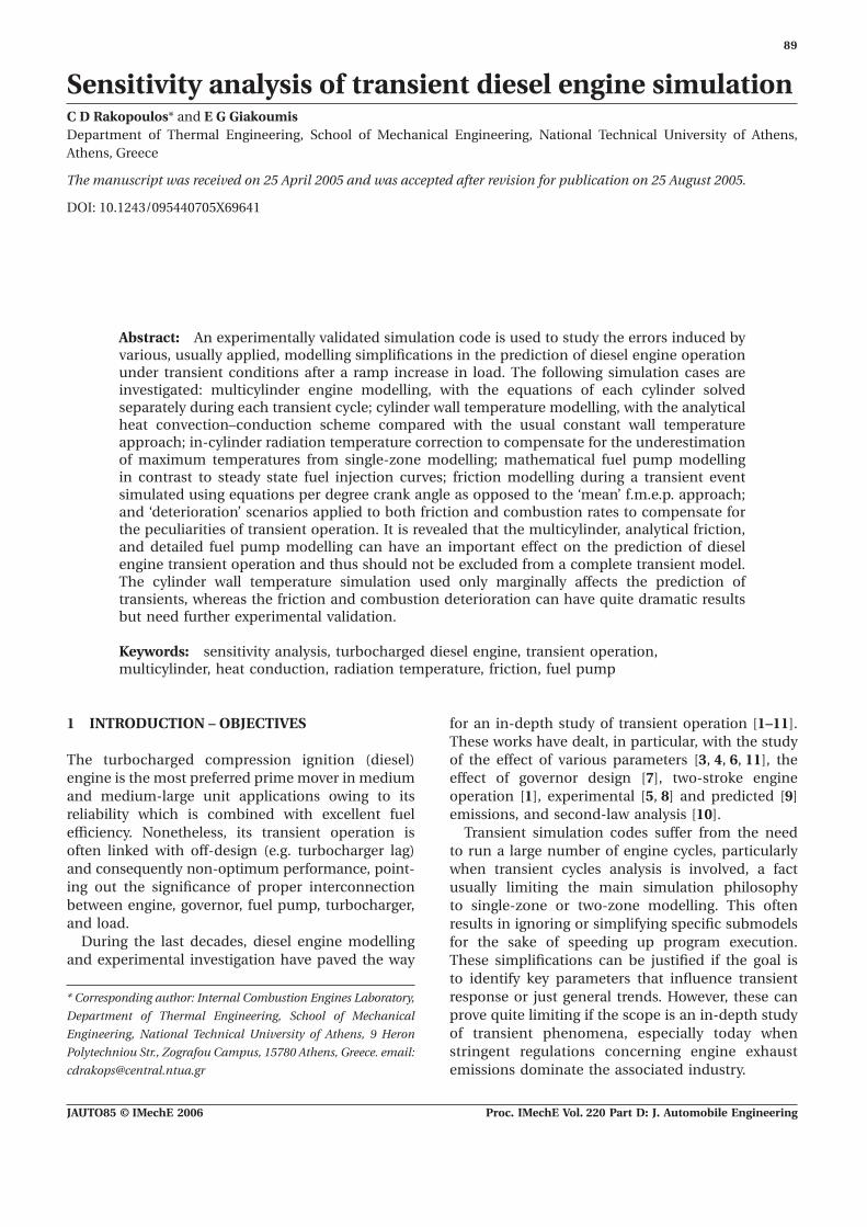
89 Sensitivity analysis of transient diesel engine simulation C D Rakopoulos* and E G Giakoumis Department of Thermal Engineering, School of Mechanical Engineering, National Technical University of Athens, Athens, Greece The manuscript was received on 25 April 2005 and was accepted after revision for publication on 25 August 2005. DOI: 10.1243/095440705X69641 Abstract: An experimentally validated simulation code is used to study the errors induced by various, usually applied, modelling simplifications in the prediction of diesel engine operation under transient conditions after a ramp increase in load. The following simulation cases are investigated: multicylinder engine modelling, with the equations of each cylinder solved separately during each transient cycle; cylinder wall temperature modelling, with the analytical heat convection–conduction scheme compared with the usual constant wall temperature approach; in-cylinder radiation temperature correction to compensate for the underestimation of maximum temperatures from single-zone modelling; mathematical fuel pump modelling in contrast to steady state fuel injection curves; friction modelling during a transient event simulated using equations per degree crank angle as opposed to the ‘mean’ f.m.e.p. approach; and ‘deterioration’ scenarios applied to both friction and combustion rates to compensate for the peculiarities of transient operation. It is revealed that the multicylinder, analytical friction, and detailed fuel pump modelling can have an important effect on the prediction of diesel engine transient operation and thus should not be excluded from a complete transient model. The cylinder wall temperature simulation used only marginally affects the prediction of transients, whereas the friction and combustion deterioration can have quite dramatic results but need further experimental validation. Keywords: sensitivity analysis, turbocharged diesel engine, transient operation, multicylinder, heat conduction, radiation temperature, friction, fuel pump 1 INTRODUCTION – OBJECTIVES for an in-depth study of transient operation [1–11]. These works have dealt, in particular, with the study of the effect of various parameters [3, 4, 6, 11], the The turbocharged compression ignition (diesel) engine is the most preferred prime mover in medium effect of governor design [7], two-stroke engine operation [1], experimental [5, 8] and predicted [9] and medium-large unit applications owing to its reliability which is combined with excellent fuel emissions, and second-law analysis [10]. efficiency. Nonetheless, its transient operation is Transient simulation codes suffer from the need often linked with off-design (e.g. turbocharger lag) to run a large number of engine cycles, particularly and consequently non-optimum performance, point- when transient cycles analysis is involved, a fact ing out the significance of proper interconnection usually limiting the main simulation philosophy between engine, governor, fuel pump, turbocharger, to single-zone or two-zone modelling. This often and load. results in ignoring or simplifying specific submodels During the last decades, diesel engine modelling for the sake of speeding up program execution. and experimental investigation have paved the way These simplifications can be justified if the goal is to identify key parameters that influence transient response or just general trends. However, these can * Corresponding author: Internal Combustion Engines Laboratory, prove quite limiting if the scope is an in-depth study Department of Thermal Engineering, School of Mechanical of transient phenomena, especially today when Engineering, National Technical University of Athens, 9 Heron stringent regulations concerning engine exhaust Polytechniou Str., Zografou Campus, 15780 Athens, Greece. email: [email protected] emissions dominate the associated industry. JAUTO85 © IMechE 2006 Proc. IMechE Vol. 220 Part D: J. Automobile Engineering
Transcript of Sensitivity analysis of transient diesel engine...
89
Sensitivity analysis of transient diesel engine simulationC D Rakopoulos* and E G GiakoumisDepartment of Thermal Engineering, School of Mechanical Engineering, National Technical University of Athens,Athens, Greece
The manuscript was received on 25 April 2005 and was accepted after revision for publication on 25 August 2005.
DOI: 10.1243/095440705X69641
Abstract: An experimentally validated simulation code is used to study the errors induced byvarious, usually applied, modelling simplifications in the prediction of diesel engine operationunder transient conditions after a ramp increase in load. The following simulation cases areinvestigated: multicylinder engine modelling, with the equations of each cylinder solvedseparately during each transient cycle; cylinder wall temperature modelling, with the analyticalheat convection–conduction scheme compared with the usual constant wall temperatureapproach; in-cylinder radiation temperature correction to compensate for the underestimationof maximum temperatures from single-zone modelling; mathematical fuel pump modellingin contrast to steady state fuel injection curves; friction modelling during a transient eventsimulated using equations per degree crank angle as opposed to the ‘mean’ f.m.e.p. approach;and ‘deterioration’ scenarios applied to both friction and combustion rates to compensate forthe peculiarities of transient operation. It is revealed that the multicylinder, analytical friction,and detailed fuel pump modelling can have an important effect on the prediction of dieselengine transient operation and thus should not be excluded from a complete transient model.The cylinder wall temperature simulation used only marginally affects the prediction oftransients, whereas the friction and combustion deterioration can have quite dramatic resultsbut need further experimental validation.
Keywords: sensitivity analysis, turbocharged diesel engine, transient operation,multicylinder, heat conduction, radiation temperature, friction, fuel pump
1 INTRODUCTION – OBJECTIVES for an in-depth study of transient operation [1–11].These works have dealt, in particular, with the studyof the effect of various parameters [3, 4, 6, 11], theThe turbocharged compression ignition (diesel)
engine is the most preferred prime mover in medium effect of governor design [7], two-stroke engineoperation [1], experimental [5, 8] and predicted [9]and medium-large unit applications owing to its
reliability which is combined with excellent fuel emissions, and second-law analysis [10].efficiency. Nonetheless, its transient operation is Transient simulation codes suffer from the needoften linked with off-design (e.g. turbocharger lag) to run a large number of engine cycles, particularlyand consequently non-optimum performance, point- when transient cycles analysis is involved, a facting out the significance of proper interconnection usually limiting the main simulation philosophybetween engine, governor, fuel pump, turbocharger, to single-zone or two-zone modelling. This oftenand load. results in ignoring or simplifying specific submodels
During the last decades, diesel engine modelling for the sake of speeding up program execution.and experimental investigation have paved the way These simplifications can be justified if the goal is
to identify key parameters that influence transientresponse or just general trends. However, these can* Corresponding author: Internal Combustion Engines Laboratory,
prove quite limiting if the scope is an in-depth studyDepartment of Thermal Engineering, School of Mechanical
of transient phenomena, especially today whenEngineering, National Technical University of Athens, 9 Heron
stringent regulations concerning engine exhaustPolytechniou Str., Zografou Campus, 15780 Athens, Greece. email:
[email protected] emissions dominate the associated industry.
JAUTO85 © IMechE 2006 Proc. IMechE Vol. 220 Part D: J. Automobile Engineering

90 C D Rakopoulos and E G Giakoumis
Typical modelling simplifications include: engine cycle [12, 13]. Its magnitude compared withthe brake torque is not negligible, particularly at low
(a) single-zone modelling; loads where the most demanding transient events(b) the assumption of constant cylinder wall temper- commence. Friction modelling in transient simulation
ature throughout the whole transient test; codes has always been used in the form of mean(c) the solution of the equations of one cylinder by f.m.e.p. relations, remaining constant for every degree
assuming that all the others behave in the same crank angle in each cycle in the model simulation,way for each transient cycle; thus limiting the effect of real friction torque in the
(d) the use of steady state fuel injection data; predictive capabilities of the model. The sensitivity(e) the use of steady state turbocharger data; of the predictions to friction modelling errors was(f) the use of steady state dynamometer curves; investigated, among other issues, by Watson [3]. In(g) filling and emptying modelling of exhaust mani- the present paper, the more fundamental method
fold operation; proposed by Taraza et al. [13] is used for analytical(h) the simulation of friction torque with the use of modelling of each friction component. This method
mean friction mean effective pressure (f.m.e.p.) separates friction torque into four terms, allowing forrelations; detailed modelling at each degree crank angle.
(i) assumptions that both combustion and friction Furthermore, during transient operation bothbehave during transients in the same way as they friction [14] and combustion [9, 14, 15] are charac-do under steady state operation. terized by non-steady state behaviour, differentiating
engine response and performance when comparedIt is the intention of the present work to investigate
with the corresponding steady state values, at the samemany of the above simplifications in order to be
engine speed and fuelling conditions. Winterboneable to estimate their validity and evaluate theirand Loo [1] assumed that friction torque should beimportance in transient simulation codes. To this end,generally overestimated during the transient eventfirstly a multicylinder engine modelling scheme isby some percentage, to account for the peculiaritiesapplied where all differential and algebraic equationsof transient operation. This aspect has also beenare solved separately and sequentially for eachinvestigated by the present research group for acylinder. By so doing, the ‘single-cylinder’ solutionnaturally aspirated compression ignition engine [6],approach will be put to the test and possible differ-where transient friction torque was increased inences in the performance of cylinders during the samerelation to the instantaneous crankshaft deceleration.engine cycle of a transient event will be revealed.Winterbone and Tennant [14] found that, duringThe cylinder wall temperature profile adopted, i.e. atransients initiated from load increases, the mixingconstant wall temperature assumption as opposed toprocess became poorer, probably owing to over-a detailed heat convection–conduction scheme, willpenetration resulting in deposition of fuel on thebe studied, as well as the use of corrected radiationpiston.temperatures during combustion to compensate for
A transient diesel engine simulation code hasthe underestimation of gas temperatures during thebeen developed by the present authors that incor-combustion period from single-zone modelling.porates some important features to account for theOne of the most important parts that influencepeculiarities of the transient operations. Detailedtransient response is the fuel injection system. It isrelations concerning fuel injection, combustion,strongly suspected that the use of steady state fueldynamic analysis, heat transfer to the cylinder walls,pump curves (as is the case with most transientand turbocharger with aftercooler operation duringsimulations so far) can be quite limiting in terms oftransient response have been developed and validatedaccurate dynamic engine prediction, since the fuel[6, 7, 11].pump experiences a transient operation of its own
The sensitivity analysis carried out will be given induring the engine speed or load change. To this end,a series of diagrams that depict speed as well as othera detailed fuel injection pump submodel, whichinteresting engine variable responses such as fuelmathematically analyses the processes inside the fuelpump rack position or boost pressure. Owing to thepump, will be integrated in the transient simulationnarrow speed range of the engine in hand, only loadcode and its results will be compared with thoseincreases under a constant governor setting arederived using steady state fuel pump curves.investigated, which nonetheless play a significantThe effect of a detailed, per degree crank angle,role in the European transient cycles of heavy-dutymodelling of friction components is also focused
upon. Friction torque varies significantly during an vehicles [16].
JAUTO85 © IMechE 2006Proc. IMechE Vol. 220 Part D: J. Automobile Engineering
91Sensitivity analysis of transient diesel engine simulation
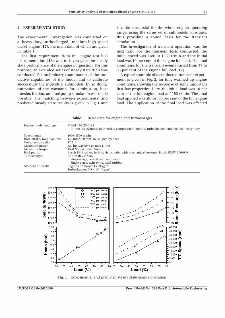
2 EXPERIMENTAL STUDY is quite successful for the whole engine operatingrange, using the same set of submodels constants,thus providing a sound basis for the transientThe experimental investigation was conducted on
a heavy-duty, turbocharged, medium-high-speed simulation.The investigation of transient operation was thediesel engine [17], the main data of which are given
in Table 1. next task. For the transient tests conducted, theinitial speed was 1180 or 1380 r/min and the initialThe first requirement from the engine test bed
instrumentation [18] was to investigate the steady load was 10 per cent of the engine full load. The finalconditions for the transient events varied from 47 tostate performance of the engine in question. For this
purpose, an extended series of steady state trials was 95 per cent of the engine full load [17].A typical example of a conducted transient experi-conducted for preliminary examination of the pre-
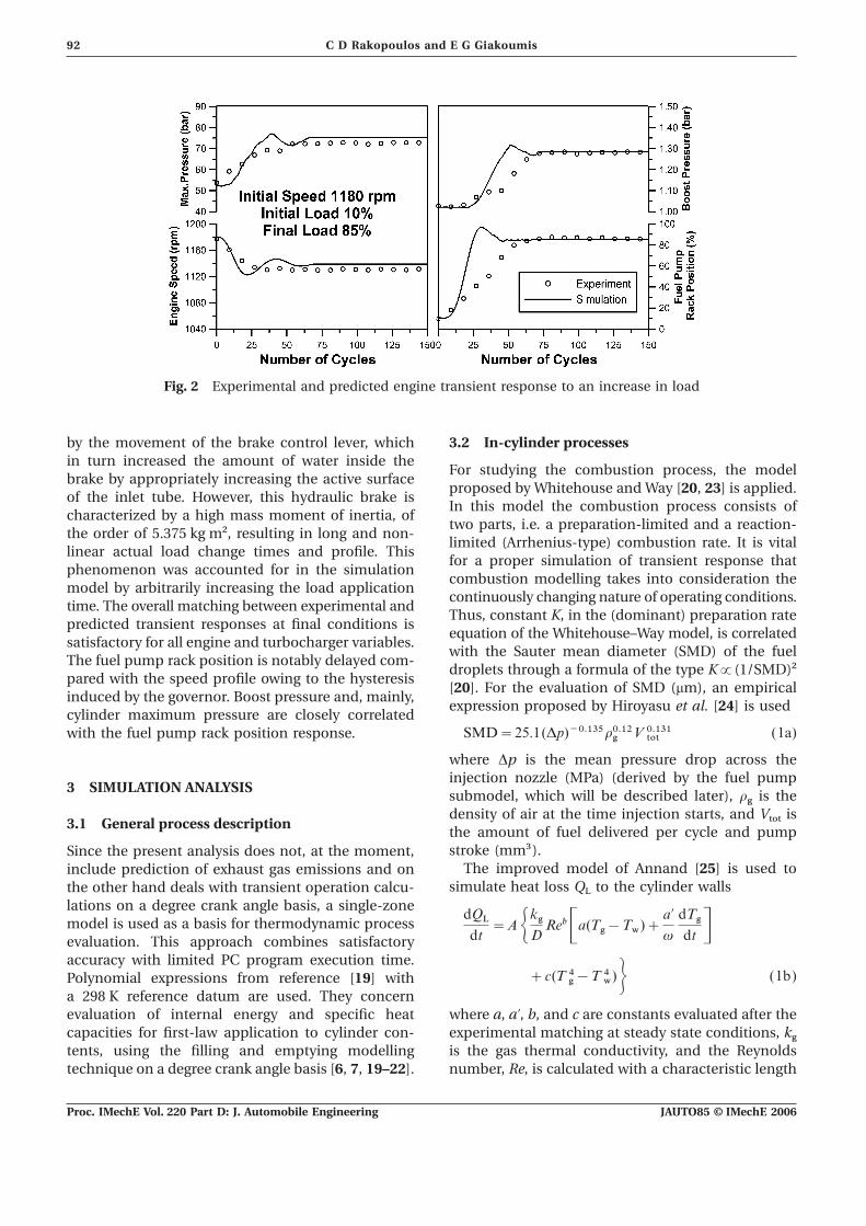
dictive capabilities of the model and to calibrate ment is given in Fig. 2, for fully warmed-up engineconditions, showing the response of some importantsuccessfully the individual submodels. By so doing,
estimation of the constants for combustion, heat first-law properties. Here, the initial load was 10 percent of the full engine load at 1180 r/min. The finaltransfer, friction, and fuel pump simulation was made
possible. The matching between experimental and load applied was almost 85 per cent of the full engineload. The application of the final load was effectedpredicted steady state results is given in Fig. 1 and
Table 1 Basic data for engine and turbocharger
Engine model and type MWM TbRHS 518SIn-line, six-cylinder, four-stroke, compression ignition, turbocharged, aftercooled, heavy-duty
Speed range 1000–1500 r/minBore/stroke/swept volume 140 mm/180 mm/16.62 l per cylinderCompression ratio 17.7 : 1Maximum power 320 hp (236 kW) at 1500 r/minMaximum torque 1520 N m at 1250 r/minFuel pump Bosch PE-P series, in-line, six-cylinder with mechanical governor Bosch RSUV 300/900Turbocharger KKK M4B 754/345
Single-stage, centrifugal compressorSingle-stage, twin-entry, axial turbine
Moment of inertia Engine and brake: 15.60 kg m2
Turbocharger: 7.5×10⁻⁴ kg m2
Fig. 1 Experimental and predicted steady state engine operation
JAUTO85 © IMechE 2006 Proc. IMechE Vol. 220 Part D: J. Automobile Engineering
92 C D Rakopoulos and E G Giakoumis
Fig. 2 Experimental and predicted engine transient response to an increase in load
by the movement of the brake control lever, which 3.2 In-cylinder processesin turn increased the amount of water inside the
For studying the combustion process, the modelbrake by appropriately increasing the active surface
proposed by Whitehouse and Way [20, 23] is applied.of the inlet tube. However, this hydraulic brake is
In this model the combustion process consists ofcharacterized by a high mass moment of inertia, of
two parts, i.e. a preparation-limited and a reaction-the order of 5.375 kg m2, resulting in long and non-
limited (Arrhenius-type) combustion rate. It is vitallinear actual load change times and profile. This
for a proper simulation of transient response thatphenomenon was accounted for in the simulation
combustion modelling takes into consideration themodel by arbitrarily increasing the load application
continuously changing nature of operating conditions.time. The overall matching between experimental and
Thus, constant K, in the (dominant) preparation ratepredicted transient responses at final conditions is
equation of the Whitehouse–Way model, is correlatedsatisfactory for all engine and turbocharger variables.
with the Sauter mean diameter (SMD) of the fuelThe fuel pump rack position is notably delayed com-
droplets through a formula of the type K3(1/SMD)2pared with the speed profile owing to the hysteresis
[20]. For the evaluation of SMD (mm), an empiricalinduced by the governor. Boost pressure and, mainly,
expression proposed by Hiroyasu et al. [24] is usedcylinder maximum pressure are closely correlated
SMD=25.1(Dp)−0.135r0.12g V 0.131tot (1a)with the fuel pump rack position response.
where Dp is the mean pressure drop across theinjection nozzle (MPa) (derived by the fuel pump
3 SIMULATION ANALYSISsubmodel, which will be described later), r
gis the
density of air at the time injection starts, and Vtot
is3.1 General process description
the amount of fuel delivered per cycle and pumpstroke (mm3).Since the present analysis does not, at the moment,
The improved model of Annand [25] is used toinclude prediction of exhaust gas emissions and onsimulate heat loss Q
Lto the cylinder wallsthe other hand deals with transient operation calcu-
lations on a degree crank angle basis, a single-zonemodel is used as a basis for thermodynamic process
dQLdt=AGkgD RebCa(Tg−Tw)+
a∞v
dTgdt Devaluation. This approach combines satisfactory
accuracy with limited PC program execution time.+c(T 4g−T 4w)H (1b)Polynomial expressions from reference [19] with
a 298 K reference datum are used. They concernevaluation of internal energy and specific heat where a, a∞, b, and c are constants evaluated after the
experimental matching at steady state conditions, kg
capacities for first-law application to cylinder con-tents, using the filling and emptying modelling is the gas thermal conductivity, and the Reynolds
number, Re, is calculated with a characteristic lengthtechnique on a degree crank angle basis [6, 7, 19–22].
JAUTO85 © IMechE 2006Proc. IMechE Vol. 220 Part D: J. Automobile Engineering
93Sensitivity analysis of transient diesel engine simulation
equal to piston diameter D and a characteristic 4 MULTICYLINDER MODELspeed, u
char, derived from a k–e zero-dimensional
turbulent kinetic model. It holds [19, 26] that At steady state operation the performance of eachcylinder is essentially the same owing to the constantposition of the governor clutch resulting in the samedE9
dt=
1
2
dm
dtu2inl−P−
E9m
dm
dtand
amount of fuel being injected per cycle.At transient operation, on the other hand, eachdk
dt=P−me−
k
m
dm
dt(1c) cylinder experiences different fuellings during the
same engine cycle owing to the continuous move-ment of the fuel pump rack, initiated by a load orwhere E9=0.5mu: 2 is the mean flow kinetic energyspeed change. These differentiations in fuelling cansupplied to the cylinder during the inlet process,result in significant differentiations in torque responsewhich is partially converted to turbulent kinetic energyand finally speed, so affecting significantly the wholek=1.5mu∞2 (isotropic turbulence) through a turbulentengine operation. As regards speed changes, only thedissipation process at a rate of P=2.7(r√kD)(u: 2/D2)first cycles are practically affected, but, when loadand finally to heat through viscous dissipation at achanges are investigated, significant variations canrate of me with e=(k/1.5m)1.5. The characteristicbe experienced throughout the transient cycle.speed is u
char=√u: 2+u∞2, which is used in the
Contrary to the usual approach, i.e. solution of theReynolds number needed in equation (1b).governing equations for one cylinder and subsequentThe temperature T
wused above corresponds to
use of suitable phasing images of the behaviour ofthe cylinder liner. Based on previous experimentallythat cylinder, a true multicylinder engine model isvalidated findings for this type of engine (for example,developed. Here, all the governing differential andreferences [19] and [21]), the piston crown temper-algebraic equations are solved individually for everyature is assumed to be 50 K higher and the cylinderone cylinder of the six-cylinder engine under study.head temperature 100 K higher than that of the linerThe dominant variable here is the fuel pump rackas computed from equation (1b).position, which moves continuously during thetransient event owing to the respective governor3.3 Engine dynamicsclutch movement, thus differentiating the amount of
The conservation of angular momentum applied to injected fuel per cylinder even in the same cycle.the total system (engine plus load) yields [2, 4] Apart from this differentiation in fuelling, each
cylinder also experiences different air mass flow-rates during the same transient engine cycle owingte(Q, v)−tload(v)−tfr(Q, v)trans=Gtot
dv
dt(2)
to the transient operation of both turbocharger com-pressor and inlet manifold. These are taken intowhere G
totis the engine-brake mass moment of
account, as both inlet and exhaust manifolds areinertia and te(Q, v) stands for the instantaneous
modelled in the PC code to exchange mass only withvalue of the engine torque. The connecting rod isthat cylinder which experiences inlet or exhaust atmodelled as a rigid body experiencing reciprocatingthe particular computational step. Consequently, noand rotating movement at the same time [6, 7]. Also,phasing image of the inlet and exhaust process of onet
load(v) is the load torque, which, for the hydraulic
cylinder through a ‘mean’ inlet and exhaust manifoldbrake coupled to the engine examined, is3v2. Lastly,simulation is applied, while at the same time inter-t
fr(Q, v)
transstands for the friction torque during
actions between exhausting cylinders, which cantransient operation, which will be analysed in detailunder certain circumstances lead to backflow, arein section 8.also taken into account. As a consequence, the useof the multicylinder engine model results in different
3.4 Turbocharger individual cylinder air–fuel ratios during an enginetransient cycle owing to the respective differentiationThe compressor and turbine operating points arein both air mass flow and fuelling rates.evaluated, for every computational step in the
This ‘multicylinder’ approach has, of course, theengine simulation code, using manufacturer’s datadrawback of increasing the computational timeat steady state conditions. These maps, which alsoalmost linearly to the number of cylinders involved,include turbine isentropic efficiency variation, havebut it is capable of providing more accuracy with thebeen incorporated into the PC code in the form of
second-order polynomial expressions [27]. transient operation phenomena. Moreover, it can
JAUTO85 © IMechE 2006 Proc. IMechE Vol. 220 Part D: J. Automobile Engineering

94 C D Rakopoulos and E G Giakoumis
offer better results as regards manifold simulation period where the fuel pump rack position reaches itsmaximum point, there is a clearly distinguishableeven at steady state conditions. The engine under
study, being a six-cylinder one, has a twin-entry difference in the values of l owing to both fuellingand air quantity differentiations between the cylindersturbine. This means that its exhaust manifold con-
sists of two parts, one of which communicates with (of the order of 7.5 per cent maximum) during thesame engine cycle. Similarly, all other variables thatcylinders 1 to 3 and the other with cylinders 4 to 6.
This particular configuration has also been taken into depend on the fuelling rate or air fuel quantity,i.e. instantaneous cylinder pressures, indicated meanconsideration in the simulation results described
below. effective pressure, blow-by losses, heat flux, bearingloading, etc., are also differentiated from cylinder toFigure 3 is a typical representation of the results
obtained using the multicylinder engine modelling cylinder during the same transient cycle, affecting inthis way the whole engine transient response.approach. The total moment of inertia is halved
for the sake of this investigation. For the nominal The above finding is expanded in Fig. 4, wherethe pressure and temperature diagrams of the sametransient case of 10–70 per cent load increase, the
response of the relative air–fuel ratio, l (i.e. the actual cylinders are depicted for cycles 5 and 15 of thenominal load increase case of 10–70 per cent. Bothair–fuel ratio divided by its stoichiometric value), and
the respective maximum (main chamber) pressure the pressure and temperature of the main chambercan take up to 5 per cent greater values when theof the first and last cylinders in firing order are
depicted. The case with 10–95 per cent engine load first and the last cylinders in firing order are underinvestigation.increase is also given for comparison. Apart from the
Fig. 3 Response of the first and last cylinders in firing order to an increase in load
Fig. 4 Main chamber pressure and temperature distribution of first and last cylinders in firingorder during specific cycles of transient event
JAUTO85 © IMechE 2006Proc. IMechE Vol. 220 Part D: J. Automobile Engineering
95Sensitivity analysis of transient diesel engine simulation
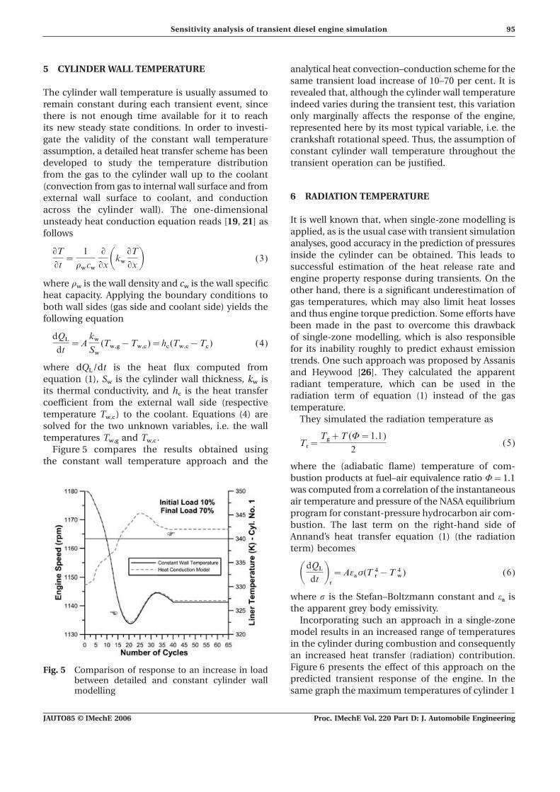
5 CYLINDER WALL TEMPERATURE analytical heat convection–conduction scheme for thesame transient load increase of 10–70 per cent. It isrevealed that, although the cylinder wall temperatureThe cylinder wall temperature is usually assumed to
remain constant during each transient event, since indeed varies during the transient test, this variationonly marginally affects the response of the engine,there is not enough time available for it to reach
its new steady state conditions. In order to investi- represented here by its most typical variable, i.e. thecrankshaft rotational speed. Thus, the assumption ofgate the validity of the constant wall temperature
assumption, a detailed heat transfer scheme has been constant cylinder wall temperature throughout thetransient operation can be justified.developed to study the temperature distribution
from the gas to the cylinder wall up to the coolant(convection from gas to internal wall surface and from
6 RADIATION TEMPERATUREexternal wall surface to coolant, and conductionacross the cylinder wall). The one-dimensional
It is well known that, when single-zone modelling isunsteady heat conduction equation reads [19, 21] asapplied, as is the usual case with transient simulationfollowsanalyses, good accuracy in the prediction of pressuresinside the cylinder can be obtained. This leads toqT
qt=
1
rwcw
qqxAkw qTqxB (3)
successful estimation of the heat release rate andengine property response during transients. On thewhere r
wis the wall density and c
wis the wall specific
other hand, there is a significant underestimation ofheat capacity. Applying the boundary conditions togas temperatures, which may also limit heat lossesboth wall sides (gas side and coolant side) yields theand thus engine torque prediction. Some efforts havefollowing equationbeen made in the past to overcome this drawbackof single-zone modelling, which is also responsibledQL
dt=A
kwSw
(Tw,g−Tw,c)=hc(Tw,c−Tc) (4)for its inability roughly to predict exhaust emissiontrends. One such approach was proposed by Assanis
where dQL
/dt is the heat flux computed from and Heywood [26]. They calculated the apparentequation (1), S
wis the cylinder wall thickness, k
wis radiant temperature, which can be used in the
its thermal conductivity, and hc
is the heat transfer radiation term of equation (1) instead of the gascoefficient from the external wall side (respective temperature.temperature T
w,c) to the coolant. Equations (4) are They simulated the radiation temperature as
solved for the two unknown variables, i.e. the walltemperatures T
w,gand T
w,c. Tr=
Tg+T (W=1.1)
2(5)
Figure 5 compares the results obtained usingthe constant wall temperature approach and the where the (adiabatic flame) temperature of com-
bustion products at fuel–air equivalence ratio W=1.1was computed from a correlation of the instantaneousair temperature and pressure of the NASA equilibriumprogram for constant-pressure hydrocarbon air com-bustion. The last term on the right-hand side ofAnnand’s heat transfer equation (1) (the radiationterm) becomes
AdQLdt B
r=Aeas(T 4r−T 4w) (6)
where s is the Stefan–Boltzmann constant and ea
isthe apparent grey body emissivity.
Incorporating such an approach in a single-zonemodel results in an increased range of temperaturesin the cylinder during combustion and consequentlyan increased heat transfer (radiation) contribution.Figure 6 presents the effect of this approach on theFig. 5 Comparison of response to an increase in loadpredicted transient response of the engine. In thebetween detailed and constant cylinder wall
modelling same graph the maximum temperatures of cylinder 1
JAUTO85 © IMechE 2006 Proc. IMechE Vol. 220 Part D: J. Automobile Engineering

96 C D Rakopoulos and E G Giakoumis
operation of its own during the dynamic conditionsof the engine with a very possible differentiation inthe amount of injected fuel per cylinder comparedwith the one under similar (engine speed and fuelpump rack position) steady state conditions. This isin conformity with the experimental remarks madeby Murayama et al. [15].
A mathematical fuel injection model, experi-mentally validated at steady state conditions, isapplied to simulate the fuel pump injector liftmechanism [28], taking into account the deliveryvalve and injector needle motion. The unsteady gasflow equations are solved using the method of charac-teristics, providing the dynamic injection timing aswell as the duration and the rate of injection foreach cylinder at each transient cycle. The obviousFig. 6 Comparison of response to an increase in loadadvantage here is that the transient operation ofbetween conventional and corrected radiationthe fuel pump is also taken into account, through thetemperature modellingfuel pump residual pressure, which is built uptogether with the other variables during the transientare depicted, with the nominal temperature foundevent. Moreover, this individual fuel injection sub-
from the conventional analysis that underestimatesroutine is called upon once for every cylinder at each
maximum cylinder temperature by up to 500 K, ascycle with the values of angular velocity, fuel pump
can be concluded from the radiation model curve.rack position, and pump residual pressure existing
The effect on the engine speed response is alsoat the point of static injection timing of the individual
obvious, affecting both the maximum (5.5 per cent) cylinder. The time burden imposed by the particularand the final speed droop (4.2 per cent). However, subroutine is not of concern, since it is executed inno distinguishable differences are observed during not more than 0.2 s in a typical PC. The results, forthe first cycles where the fuelling is still kept at low application of both fuel injection approaches, arelevels. depicted in Fig. 7, where a difference of the order of
8 per cent is observed in the lowest engine speed(and consequently the other engine variables). These
7 FUEL PUMP OPERATION confirm the initial suspicions and highlight theimportance of incorporating a fuel pump model
The amount of fuel injected per cycle and cylinder, when dealing with dynamic engine calculations.in the majority of the transient simulations, is foundby applying the steady state fuel pump curves at theinstantaneous values of engine speed and fuel pump 8 FRICTION MODELLINGrack position of cylinder 1 for every transient cycle.This approach constitutes a rather coarse simplifi- For the calculation of friction inside the cylinder, the
method used so far by all other researchers in thecation, since the fuel pump experiences a transient
Fig. 7 Comparison of response to an increase in load between steady state and detailed fuelpump modelling
JAUTO85 © IMechE 2006Proc. IMechE Vol. 220 Part D: J. Automobile Engineering

97Sensitivity analysis of transient diesel engine simulation
field, i.e. the mean f.m.e.p. approach [29], is com- in fuelling occurs, a fact leading to differentiationsin gas pressure and consequently in the profile ofpared with the detailed method proposed by Taraza
et al. [13]. The latter method describes the non-steady friction torque and thus engine speed. The meanf.m.e.p. results differ by almost 6 per cent as regardsprofile of friction torque during each cycle on the
basis of fundamental friction analysis. In this method final equilibrium speed and consequently in all otherengine and turbocharger variable responses. This isthe total amount of friction is divided into four parts,
i.e. piston ring assembly, loaded bearings, valvetrain, due to the considerable underestimation of frictiontorque around firing TDC that the mean f.m.e.p.and auxiliaries. Piston ring friction analysis (including
the piston ring and piston skirt contributions) is assumption induces. Higher load changes and moredemanding load types lead to more abrupt governorbased on fundamental lubrication theory and was
validated with experimental data. It is based on the clutch movements and so greater crankshaft angulardecelerations, revealing the differentiation in thefact that lubrication is hydrodynamic for most of the
piston stroke, with metal contact occurring near predictions from the two friction approaches.‘hot’ top dead centre. Bearing friction is mainlyhydrodynamic with the deformation of the bearinghousing on account of the applied loading playing
9 DETERIORATION DURING TRANSIENTan important role. Valvetrain friction is governed
OPERATIONby friction between cam and tappet and is mainlyelastohydrodynamic. Moreover, account of engine
9.1 Combustionoil temperature effects on total friction through theuse of oil kinematic viscosity is another important Murayama et al. [15] studied the acceleration
behaviour of a single-cylinder, naturally aspiratedaspect of this friction model. Detailed description ofthe model can be found in references [13] and [30]. diesel engine. They found that, owing to rapid and
considerable changes in fuelling, instantaneousThe total friction torque at each degree crank angleis the sum of the above terms and it varies con- torsional deformations in the driving system of
the fuel injection pump were taking place, leadingtinuously during the engine cycle, unlike the meanf.m.e.p. equation where friction torque remains to an incomplete combustion, which steady state
combustion modelling was unable to predict.constant.Figure 8 investigates the effect of friction modelling At the same time, Winterbone and Tennant [14],
working on a six-cylinder, turbocharged dieseladopted for a 10–95 per cent load change and for alinear load type. Fuel pump rack position and boost engine, found that the combustion process some-
how deteriorated during transient operation after apressure response are also depicted for this loadchange, the load–torque of which is given in the load increase. They applied the same combustion
modelling with the one in this study, i.e. the funda-upper right subdiagram. The two speed curves almostcoincide only until cycle 15 where the main change mental Whitehouse–Way approach, and concluded
Fig. 8 Comparison of response to an increase in load between mean f.m.e.p. and analyticalfriction modelling
JAUTO85 © IMechE 2006 Proc. IMechE Vol. 220 Part D: J. Automobile Engineering
98 C D Rakopoulos and E G Giakoumis
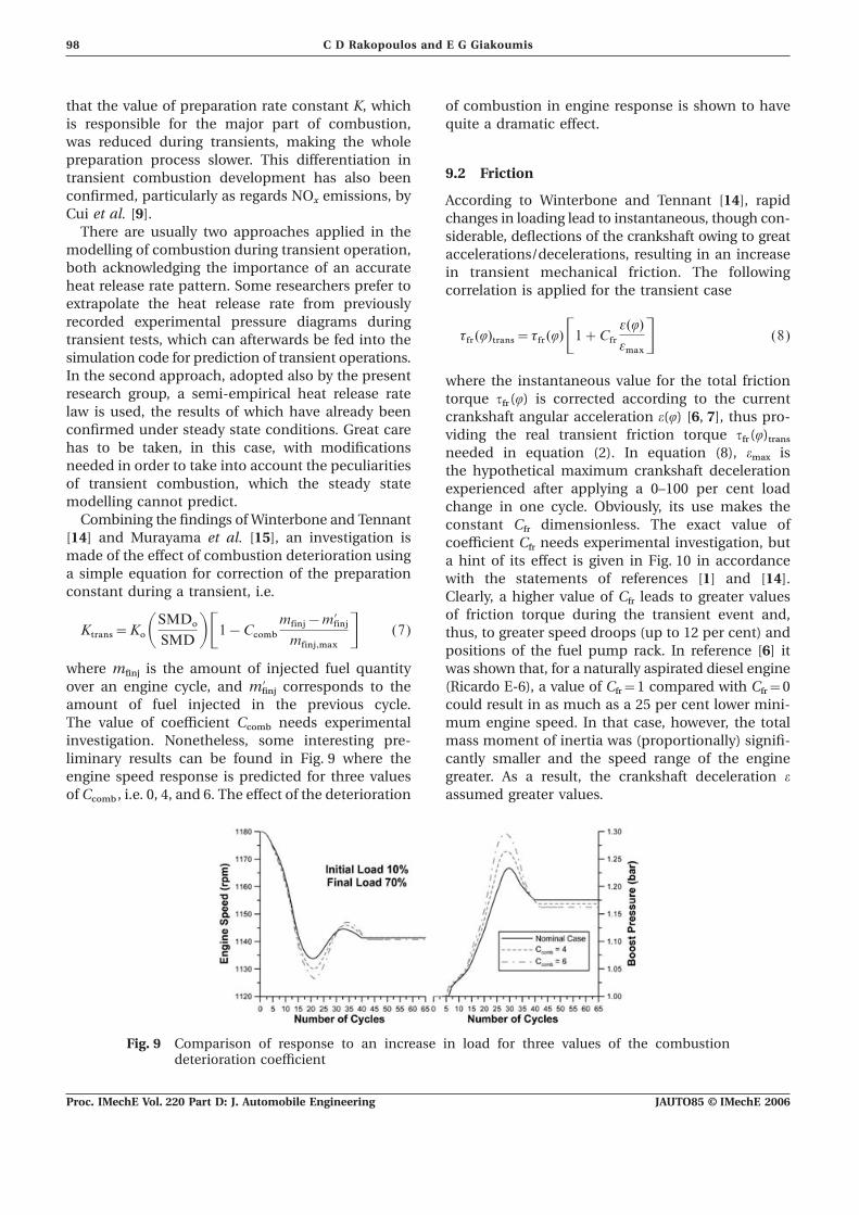
that the value of preparation rate constant K, which of combustion in engine response is shown to havequite a dramatic effect.is responsible for the major part of combustion,
was reduced during transients, making the wholepreparation process slower. This differentiation in
9.2 Frictiontransient combustion development has also beenconfirmed, particularly as regards NO
xemissions, by According to Winterbone and Tennant [14], rapid
Cui et al. [9]. changes in loading lead to instantaneous, though con-There are usually two approaches applied in the siderable, deflections of the crankshaft owing to great
modelling of combustion during transient operation, accelerations/decelerations, resulting in an increaseboth acknowledging the importance of an accurate in transient mechanical friction. The followingheat release rate pattern. Some researchers prefer to correlation is applied for the transient caseextrapolate the heat release rate from previouslyrecorded experimental pressure diagrams during
tfr(Q)trans=tfr(Q)C1+Cfre(Q)
emaxD (8)transient tests, which can afterwards be fed into thesimulation code for prediction of transient operations.In the second approach, adopted also by the present where the instantaneous value for the total frictionresearch group, a semi-empirical heat release rate torque t
fr(Q) is corrected according to the current
law is used, the results of which have already been crankshaft angular acceleration e(Q) [6, 7], thus pro-confirmed under steady state conditions. Great care viding the real transient friction torque t
fr(Q)
transhas to be taken, in this case, with modifications needed in equation (2). In equation (8), emax
isneeded in order to take into account the peculiarities the hypothetical maximum crankshaft decelerationof transient combustion, which the steady state experienced after applying a 0–100 per cent loadmodelling cannot predict. change in one cycle. Obviously, its use makes the
Combining the findings of Winterbone and Tennant constant Cfr
dimensionless. The exact value of[14] and Murayama et al. [15], an investigation is coefficient C
frneeds experimental investigation, but
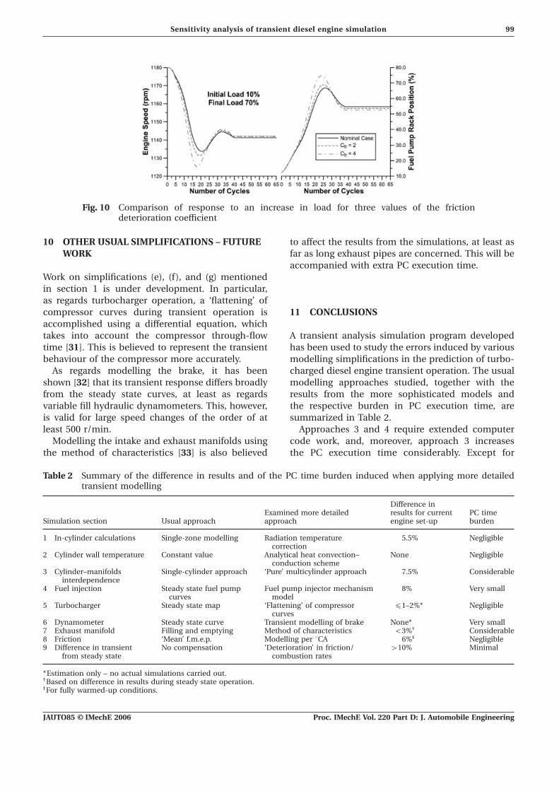
made of the effect of combustion deterioration using a hint of its effect is given in Fig. 10 in accordancea simple equation for correction of the preparation with the statements of references [1] and [14].constant during a transient, i.e. Clearly, a higher value of C
frleads to greater values
of friction torque during the transient event and,Ktrans=KoASMDo
SMD BC1−Ccombmfinj−m∞finj
mfinj,max D (7) thus, to greater speed droops (up to 12 per cent) andpositions of the fuel pump rack. In reference [6] itwas shown that, for a naturally aspirated diesel enginewhere m
finjis the amount of injected fuel quantity
over an engine cycle, and m∞finj
corresponds to the (Ricardo E-6), a value of Cfr=1 compared with C
fr=0
could result in as much as a 25 per cent lower mini-amount of fuel injected in the previous cycle.The value of coefficient C
combneeds experimental mum engine speed. In that case, however, the total
mass moment of inertia was (proportionally) signifi-investigation. Nonetheless, some interesting pre-liminary results can be found in Fig. 9 where the cantly smaller and the speed range of the engine
greater. As a result, the crankshaft deceleration eengine speed response is predicted for three valuesof C
comb, i.e. 0, 4, and 6. The effect of the deterioration assumed greater values.
Fig. 9 Comparison of response to an increase in load for three values of the combustiondeterioration coefficient
JAUTO85 © IMechE 2006Proc. IMechE Vol. 220 Part D: J. Automobile Engineering
99Sensitivity analysis of transient diesel engine simulation
Fig. 10 Comparison of response to an increase in load for three values of the frictiondeterioration coefficient
10 OTHER USUAL SIMPLIFICATIONS – FUTURE to affect the results from the simulations, at least asfar as long exhaust pipes are concerned. This will beWORKaccompanied with extra PC execution time.
Work on simplifications (e), (f), and (g) mentionedin section 1 is under development. In particular,as regards turbocharger operation, a ‘flattening’ ofcompressor curves during transient operation is 11 CONCLUSIONSaccomplished using a differential equation, whichtakes into account the compressor through-flow A transient analysis simulation program developed
has been used to study the errors induced by varioustime [31]. This is believed to represent the transientbehaviour of the compressor more accurately. modelling simplifications in the prediction of turbo-
charged diesel engine transient operation. The usualAs regards modelling the brake, it has beenshown [32] that its transient response differs broadly modelling approaches studied, together with the
results from the more sophisticated models andfrom the steady state curves, at least as regardsvariable fill hydraulic dynamometers. This, however, the respective burden in PC execution time, are
summarized in Table 2.is valid for large speed changes of the order of atleast 500 r/min. Approaches 3 and 4 require extended computer
code work, and, moreover, approach 3 increasesModelling the intake and exhaust manifolds usingthe method of characteristics [33] is also believed the PC execution time considerably. Except for
Table 2 Summary of the difference in results and of the PC time burden induced when applying more detailedtransient modelling
Difference inExamined more detailed results for current PC time
Simulation section Usual approach approach engine set-up burden
1 In-cylinder calculations Single-zone modelling Radiation temperature 5.5% Negligiblecorrection
2 Cylinder wall temperature Constant value Analytical heat convection– None Negligibleconduction scheme
3 Cylinder–manifolds Single-cylinder approach ‘Pure’ multicylinder approach 7.5% Considerableinterdependence
4 Fuel injection Steady state fuel pump Fuel pump injector mechanism 8% Very smallcurves model
5 Turbocharger Steady state map ‘Flattening’ of compressor ∏1–2%* Negligiblecurves
6 Dynamometer Steady state curve Transient modelling of brake None* Very small7 Exhaust manifold Filling and emptying Method of characteristics <3%† Considerable8 Friction ‘Mean’ f.m.e.p. Modelling per °CA 6%‡ Negligible9 Difference in transient No compensation ‘Deterioration’ in friction/ >10% Minimal
from steady state combustion rates
*Estimation only – no actual simulations carried out.†Based on difference in results during steady state operation.‡For fully warmed-up conditions.
JAUTO85 © IMechE 2006 Proc. IMechE Vol. 220 Part D: J. Automobile Engineering
100 C D Rakopoulos and E G Giakoumis
11 Rakopoulos, C. D., Giakoumis, E. G., Hountalas,the detailed heat convection–conduction schemeD. T., and Rakopoulos, D. C. The effect of various(approach 2), all other approaches prove to have andynamic, thermodynamic and design parametersimportant effect on the predicted engine response ason the performance of a turbocharged diesel engine
regards maximum engine speed droop and turbo- operating under transient load conditions. SAEcharger and engine final conditions. As such, they paper 2004-01-0926, 2004.should be included in a transient simulation code. 12 Rezeka, S. F. and Henein, N. A. A new approach to
It is strongly felt that even greater differences evaluate instantaneous friction and its componentsin internal combustion engines. SAE paper 840179,between the simplified and the more detailed1984.modelling approaches exist. These could not be
13 Taraza, D., Henein, N., and Bryzik, W. Frictionrevealed owing to the high mass moment of inertialosses in multi-cylinder diesel engines. SAE paperof the engine under study and its narrow speed2000-01-0921, 2000.
range. 14 Winterbone, D. E. and Tennant, D. W. H. Thevariation of friction and combustion rates duringdiesel engine transients. SAE paper 810339, 1981.
15 Murayama, T., Miyamoto, N., Tsuda, T., Suzuki, M.,and Hasegawa, S. Combustion behaviors underREFERENCESaccelerating operation of an IDI diesel engine. SAEpaper 800966, 1980.1 Winterbone, D. E. and Loo, W. Y. A dynamic simu-
16 http://www.dieselnet.com/standards/cycles/lation of a two-stroke turbocharged diesel engine.etc.htmlSAE paper 810337, 1981.
17 Rakopoulos, C. D., Giakoumis, E. G., and2 Watson, N. and Marzouk, M. A non-linear digitalHountalas, D. T. Experimental and simulationsimulation of turbocharged diesel engines underanalysis of the transient operation of a turbochargedtransient conditions. SAE paper 770123, 1977.multi-cylinder IDI diesel engine. Energy Res., 1998,3 Watson, N. Transient performance simulation and22, 317–331.analysis of turbocharged diesel engines. SAE paper
18 Zhao, H. and Ladommatos, N. Engine combustion810338, 1981.instrumentation and diagnostics, 2001 (Society of4 Winterbone, D. E. Transient performance. In TheAutomotive Engineers, Warrendale, Pennsylvania).thermodynamics and gas dynamics of internal
19 Heywood, J. B. Internal combustion engine funda-combustion engines (Eds J. H. Horlock and D. E.mentals, 1988 (McGraw-Hill, New York).Winterbone), Vol. 2, 1986 (Clarendon Press, Oxford).
20 Benson, R. S. and Whitehouse, N. D. Internal com-5 Arcoumanis, C., Megaritis, A., and Bazari, Z.bustion engines, 1979 (Pergamon Press, Oxford).Analysis of transient exhaust emissions in a turbo-
21 Stone, R. Introduction to internal combustion engines,charged vehicle diesel engine. In IMechE Conference3rd edition, 1999 (Macmillan, London).on Turbocharging and Turbochargers, 1994, paper
22 Rakopoulos, C. D., Rakopoulos, D. C., Giakoumis,C484/038, pp. 71–81 (Institution of MechanicalE. G., and Kyritsis, D. C. Validation and sensitivityEngineers, London).analysis of a two-zone diesel engine model for com-6 Rakopoulos, C. D. and Giakoumis, E. G. Simulationbustion and emissions prediction. Energy Conversionand analysis of a naturally aspirated, indirectManagmt, 2004, 45, 1471–1495.injection diesel engine under transient conditions
23 Whitehouse, N. D. and Way, R. G. B. Rate of heatcomprising the effect of various dynamic and thermo-release in diesel engines and its correlation with fueldynamic parameters. Energy Conversion Managmt,injection data. Proc. IMechE, Part 3J, 1969–70, 184,1998, 39, 465–484.17–27.7 Rakopoulos, C. D., Giakoumis, E. G., and
24 Hiroyasu, H., Kadota, T., and Arai, M. DevelopmentHountalas, D. T. A simulation analysis of the effectand use of a spray combustion modelling to predictof governor technical characteristics and type on thediesel engine efficiency and pollutant emissions.transient performance of a naturally aspirated IDIBull. Jap. Soc. Mech. Engrs, 1983, 26, 569–76.diesel engine. SAE paper 970633, 1997; Trans. SAE,
25 Annand, W. J. D. and Ma, T. H. InstantaneousJ. Engines, 1997, 106, 905–922.heat transfer rates to the cylinder head surface of a8 Lindgren, M. and Hansson, P. A. Effects of transientsmall compression-ignition engine. Proc. IMechE,conditions on exhaust emissions from two non-road1970–71, 185, 976–987.diesel engines. Biosyst. Engng, 2004, 87, 57–66.
26 Assanis, D. N. and Heywood, J. B. Development9 Cui, Y., Deng, K., and Wu, J. A modeling and experi-and use of a computer simulation of the turbo-mental study of transient NO
xemissions in turbo-
compounded diesel engine performance and com-charged DI diesel engines. Proc. IMechE, Part D:ponent heat transfer studies. SAE paper 860329,J. Automobile Engineering, 2004 218, 535–541.1986.10 Rakopoulos, C. D. and Giakoumis, E. G. Availability
27 Watson, N. and Janota, M. S. Turbocharginganalysis of a turbocharged diesel engine operatingthe internal combustion engine, 1982 (Macmillan,under transient load conditions. Energy, 2004, 29,
1085–1104. London).
JAUTO85 © IMechE 2006Proc. IMechE Vol. 220 Part D: J. Automobile Engineering

101Sensitivity analysis of transient diesel engine simulation
28 Rakopoulos, C. D. and Hountalas, D. T. A simu- k thermal conductivity (W/m K) andlation analysis of a DI diesel engine fuel injection turbulent kinetic energy (kg m2/s2)system fitted with a constant pressure valve. Energy K combustion model preparation rateConversion Managmt, 1996, 37, 135–150.
constant29 Ciulli, E. A review of internal combustion enginem mass (kg)losses. Part 2: studies for global evaluations. Proc.N engine speed (r/min)IMechE, Part D: J. Automobile Engineering, 1993,p pressure (Pa)207, 229–240.
30 Stanley, R., Taraza, D., Henein, N., and Bryzik, W. P turbulent dissipation rate (kg m2/s3)A simplified model of the piston ring assembly. SAE Q heat loss (J)paper 1999-01-0974, 1999. r crank radius (m)
31 Fink, D. A., Cumpsty, N. A., and Greitzer, E. M. SMD Sauter mean diameter (mm)Surge dynamics in a free-spool centrifugal com-
t time (s)pressor system. Trans. ASME, J. Turbomach., 1992,TDC top dead centre114, 321–329.T absolute temperature (K)32 Hodgson, P. G. and Raine, J. K. Computer simu-
lation of a variable fill hydraulic dynamometer. u velocity (m/s)Part 2: steady state and dynamic open-loop per- V volume (m3)formance. Proc. IMechE, Part C: J. MechanicalEngineering Science, 1992, 206, 49–56. e crankshaft angular acceleration (s−2)
33 Rakopoulos, C. D., Andritsakis, E. C., andand viscous dissipation rate (m2/s3)Hountalas, D. T. The influence of the exhaust
l relative air–fuel ratiosystem unsteady gas flow and insulation on the per-r density (kg/m3)formance of a turbocharged diesel engine. Heatt torque (N m)Recovery Syst. CHP, 1995, 15, 51–72.Q crank angle measured from the BDC
position (deg)W fuel–air equivalence ratioAPPENDIXv angular velocity (rad/s)
NotationSubscripts
A surface area (m2)BDC bottom dead centre c coolant
e engine°CA degrees crank angleD cylinder bore (m) fr friction
g gasE kinetic energy (kg m2/s2)f.m.e.p. friction mean effective pressure (bar) r radiation
trans transientG mass moment of inertia (kg m2)h heat transfer coefficient (W/m2 K) w wall
JAUTO85 © IMechE 2006 Proc. IMechE Vol. 220 Part D: J. Automobile Engineering


![2012 Exhaust Emissions of Diesel Engines Operating Under Transient Conditions With Biodiesel Fuel Blends [First Author] Progress in Energy and Combustion Science](https://static.fdocuments.in/doc/165x107/55cf94df550346f57ba4fd9c/2012-exhaust-emissions-of-diesel-engines-operating-under-transient-conditions.jpg)


