SensaGuard Rectangular Flat Pack - RockwellAutomation.com · 2019-06-13 · 4 Rockwell Automation...
16
Installation Instructions Original Instructions SensaGuard Rectangular Flat Pack (These instructions are only for the Series B Version.) Catalog Numbers 440N-Z21SS2H, 440N-Z21SS2A, 440N-Z21SS2B, 440N-Z21SS2J, 440N-Z21SS2HN, 440N-Z21SS2AN, 440N-Z21SS2BN, 440N- Z21SS2JN, 440N-Z21SS2HN9, 440N-Z21SS2AN9, 440N-Z21SS2BN9, 440N-Z21SS2JN9, 440N-Z21SS2H-AS, 440N-Z21SS2HN9-FF, 440N-Z21XS2H, 440N- Z21US2A, 440N-Z21US2B, 440N-Z21US2H, 440N-Z21US2AN, 440N-Z21US2BN, 440N-Z21US2HN, 440N-Z21US2AN9, 440N-Z21US2BN9, 440N- Z21US2HN9, 440N-Z21US2J, 440N-Z21US2JN, 440N-Z21US2JN9, 440N-Z21US2H-C, 440N-Z21XU2H Introduction Installation must be in accordance with the following instructions and specifications and implemented by suitable competent personnel. Adherence to the recommended maintenance instructions forms part of the warranty. This unit is not to be used as a mechanical stop. Guard stops and guides must be fitted. This device is intended to be part of the safety-related control system of a machine. Before installation, a risk assessment is performed to determine whether the specifications of this device are suitable for all foreseeable operational and environmental characteristics. IMPORTANT SAVE THESE INSTRUCTIONS FOR FUTURE USE. Topic Page Introduction 1 Additional Resources 2 Technical Specifications 2 Dimensions 3 Mode of Operation — Status Indicator 3 Mounting Information 3 Diagnostics 3 Typical Wiring Diagram 4 Commissioning (Unique Coded Units) — Power the Sensor 4 OSSD Test Pulses 5 Timing Diagram 6 Troubleshooting 7 Application Wiring Examples 8 WARNING: Do not defeat, tamper, remove, or bypass this unit. Severe injury to personnel could result. ATTENTION: This device must be provided with a 24V DC PELV or SELV power supply that conforms to the requirements of 414-3 of IEC 60364-4-41 where provisions have been taken. To confirm that, even if an internal fault, the voltage at the outgoing terminals cannot exceed 60V DC. Improper selection or installation of the devices affects the integrity of the safety systems. Personal injury or death, property damage, or economic loss can result. Comply with ISO 14119 including section, accessibility to the installation, arrangement, and mounting, possible substitute actuation, access to the escape release, motivation to defeat, and actuation mode. Management controls, working procedures, training, and additional protective measures can be used to minimize the motivation to defeat and to manage the use and availability of spare actuators. Comply with ISO 13857 and ISO 13855 for guard openings and minimum (safe) distances. Comply with IEC 62061 or ISO 13849-1 and ISO 13849-2 for functional safety. SensaGuard™ Series A and Series B non-contact switches will only work with the appropriate series actuator. Series A and Series B actuators can be purchased separately. This product is intended for industrial/business application only. It is not intended to be used in residential applications as it may cause radio interference on other residential devices.
Transcript of SensaGuard Rectangular Flat Pack - RockwellAutomation.com · 2019-06-13 · 4 Rockwell Automation...
Installation Instructions
Original Instructions
SensaGuard Rectangular Flat Pack(These instructions are only for the Series B Version.)Catalog Numbers 440N-Z21SS2H, 440N-Z21SS2A, 440N-Z21SS2B, 440N-Z21SS2J, 440N-Z21SS2HN, 440N-Z21SS2AN, 440N-Z21SS2BN, 440N-Z21SS2JN, 440N-Z21SS2HN9, 440N-Z21SS2AN9, 440N-Z21SS2BN9, 440N-Z21SS2JN9, 440N-Z21SS2H-AS, 440N-Z21SS2HN9-FF, 440N-Z21XS2H, 440N-Z21US2A, 440N-Z21US2B, 440N-Z21US2H, 440N-Z21US2AN, 440N-Z21US2BN, 440N-Z21US2HN, 440N-Z21US2AN9, 440N-Z21US2BN9, 440N-Z21US2HN9, 440N-Z21US2J, 440N-Z21US2JN, 440N-Z21US2JN9, 440N-Z21US2H-C, 440N-Z21XU2H
IntroductionInstallation must be in accordance with the following instructions and specifications and implemented by suitable competent personnel. Adherence to the recommended maintenance instructions forms part of the warranty.
This unit is not to be used as a mechanical stop. Guard stops and guides must be fitted.
This device is intended to be part of the safety-related control system of a machine. Before installation, a risk assessment is performed to determine whether the specifications of this device are suitable for all foreseeable operational and environmental characteristics.
IMPORTANT SAVE THESE INSTRUCTIONS FOR FUTURE USE.
Topic Page
Introduction 1
Additional Resources 2
Technical Specifications 2
Dimensions 3
Mode of Operation — Status Indicator 3
Mounting Information 3
Diagnostics 3
Typical Wiring Diagram 4
Commissioning (Unique Coded Units) — Power the Sensor 4
OSSD Test Pulses 5
Timing Diagram 6
Troubleshooting 7
Application Wiring Examples 8
WARNING: Do not defeat, tamper, remove, or bypass this unit. Severe injury to personnel could result.
ATTENTION: This device must be provided with a 24V DC PELV or SELV power supply that conforms to the requirements of 414-3 of IEC 60364-4-41 where provisions have been taken. To confirm that, even if an internal fault, the voltage at the outgoing terminals cannot exceed 60V DC.
Improper selection or installation of the devices affects the integrity of the safety systems.
Personal injury or death, property damage, or economic loss can result.
Comply with ISO 14119 including section, accessibility to the installation, arrangement, and mounting, possible substitute actuation, access to the escape release, motivation to defeat, and actuation mode.
Management controls, working procedures, training, and additional protective measures can be used to minimize the motivation to defeat and to manage the use and availability of spare actuators.
Comply with ISO 13857 and ISO 13855 for guard openings and minimum (safe) distances.
Comply with IEC 62061 or ISO 13849-1 and ISO 13849-2 for functional safety.
SensaGuard™ Series A and Series B non-contact switches will only work with the appropriate series actuator. Series A and Series B actuators can be purchased separately.This product is intended for industrial/business application only. It is not intended to be used in residential applications as it may cause radio interference on other residential devices.

SensaGuard Rectangular Flat Pack
Additional Resources
You can view or download publications (including translations) at Literature Library. To order paper copies of technical documentation, contact your local Allen-Bradley distributor or Rockwell Automation sales representative.
ATTENTION: Read this document and the documents that are listed in the Additional Resources section about installation, configuration, and operation of this equipment before you install. Users are required to familiarize themselves with installation and connection instructions and requirements of all applicable codes, laws, and standards.
In accordance with applicable codes of practice, suitably trained personnel are required to implement installation, adjustments, service initiation, use, assembly, disassembly, and maintenance.
If this equipment is used in a manner that the manufacturer does not specify, the protection that is provided by the equipment can be impaired.
Resource Description
Industrial Automation Wiring and Grounding Guidelines, publication 1770-4.1
Provides general guidelines for installing a Rockwell Automation® industrial system.
Product Certifications website at Rockwell Automation Technical Data
Provides declarations of conformity, certificates, and other certification details.
ATTENTION: Do not attempt to install this device unless the installation instructions have been studied and understood. This document acts as a guide for a typical installation and is available in additional languages at Literature Library.
Technical SpecificationsAttribute Value
Safety Ratings
StandardsSafety Classification
IEC 60947-5-3, Cat. 4 PLe Per ISO 13849-1, Type 4 interlocking device according to ISO 14119 with either low (standard) or high (unique) coding, SIL CL3 per IEC 62061 and IEC 61508
Functional Safety Data PFHD = 1.32E-9 (Probability of dangerous failure per hour)T1 = 20 (Proof test interval)
Certifications CE marked for all applicable directives, c-UL-us (UL 508), and TÜV, see Rockwell Automation Technical Data
Operating Characteristics
Sensing distance, Assured ON 15 mm (0.59 in.)
Sensing distance, Assured OFF 25 mm (0.98 in.)
Operating voltage 24V DC 10%/-15% Class 2 SELV or PELV power supply
Response time (Off) 45 ms
Utilization Category according to Uele
DC-12 and DC-1324V200 mA
Frequency of operating cycle 0.25 Hz
No-load supply current < 50 mA
Outputs (OSSD)
Safe state De-energized (2 x PNP, 0V), AUX energized (1 x PNP, 24V)
Run state Energized (2 x PNP, 24V), AUX de-energized (1 x PNP, 0V)
Load current 200 mA maximum
Voltage drop < 1.5V
Switches connected in series Unlimited, see Timing Diagram on page 6.
Mechanical
Sensor case material Polycarbonate
Actuator case material Polycarbonate
Environmental
Operating temperature -25…+70°C (-13…+158°F)
Operating humidity 5…95% relative
Washdown rating IP66, IP67, IP69K
Shock and Vibration IEC 60068-2-27 — 30 g, 11 msIEC 60068-2-6 — 10…55 Hz
Pollution Degree IEC 60947-1 — 3
Electro-magnetic Compatibility (EMC)
Electrostatic Discharge ESDIEC 61000-4-2: air dischargePer IEC 61326-1 (functional): 8 kVPer IEC 61000-6-7 (fail-safe): 8 kV
Radiated EMF immunity IEC 61000-4-3Per IEC 61326-1 (functional): 10V/mPer IEC 61000-6-7 (fail-safe): 20V/m
Electrical Fast Transient/Burst Immunity
IEC 61000-4-4Per IEC 61326-1 (functional): 2 kV/5 kHzPer IEC 61000-6-7 (fail-safe): 2 kV/5 kHz
Conducted ImmunityIEC 61000-4-6Per IEC 61326-1 (functional): 10VPer IEC 61000-6-7 (fail-safe): 20V
Rated Impulse Withstand Voltage IEC 60947-1: 1 kV
Protection Short circuit, overload, reverse polarity, overvoltage, loss of ground
2 Rockwell Automation Publication 440N-IN018B-EN-P - April 2019

SensaGuard Rectangular Flat Pack
DimensionsFigure 1 - Actuator [mm (in.)]
Figure 2 - Sensor Dimensions [mm (in.)]
Figure 3 - Mode of Operation — Status Indicator
The actuator is supplied with the sensor.
DiagnosticsTable 1 - Unit Indicators
See Unique Coded Diagnostic on page 5 for learning sequence errors.
Mounting InformationUse non-removable screws, bolts, or nuts to mount the switch and actuator. Do not over torque the mounting hardware. Position the switch and actuator so they are aligned with each other.
Nut Torque SpecificationSwitch/Actuator: 2.20 N•m (19.5 lbs•in)
Figure 4 - Minimum Distance between Sensors
24.99(0.98)
88.14(3.47)
10.66 (0.42)
7.11 (0.28)6.78 (0.26)
4.57 (0.18)
Ø5.08(0.2)
4.57(0.18)
68.31(2.68)
18.54(0.73)
72.9(2.87)
77.98(3.07)
20.65(0.81)
24.99(0.984)
88.14(3.47)
20.65(0.813) 4.57
(0.18)
18.54 (0.73)10.67 (0.42)
13.41(0.528)
9.96(0.392) QD Connector
Version
M12 x 1
9.7(0.38)
4.57(0.18)
Ø5.08(0.2)
4.57(0.18)
77.98(3.07)
62.53(2.462)
57.96(2.282)
82.55(3.25)
Status/Diagnostic Indicator
State Status Troubleshooting
Off Not powered —
Red OSSD not active —
Green OSSD active —
Green flash
Power up test or OSSD inputs not valid
Check 24V DC or OSSD inputs (yellow or red wire)
Red flash0.5 Hz flash OSSD fault
OSSD fault—check OSSDoutputs are not shorted to GND,
24V DC or each other
2 Hz flash internal fault Cycle power
Amber flash
Actuator at maximum sensing range (-N and -N9 models
only)Move actuator closer to sensor
Status Indicator
50 mm (1.97 in.)
Rockwell Automation Publication 440N-IN018B-EN-P - April 2019 3
SensaGuard Rectangular Flat Pack
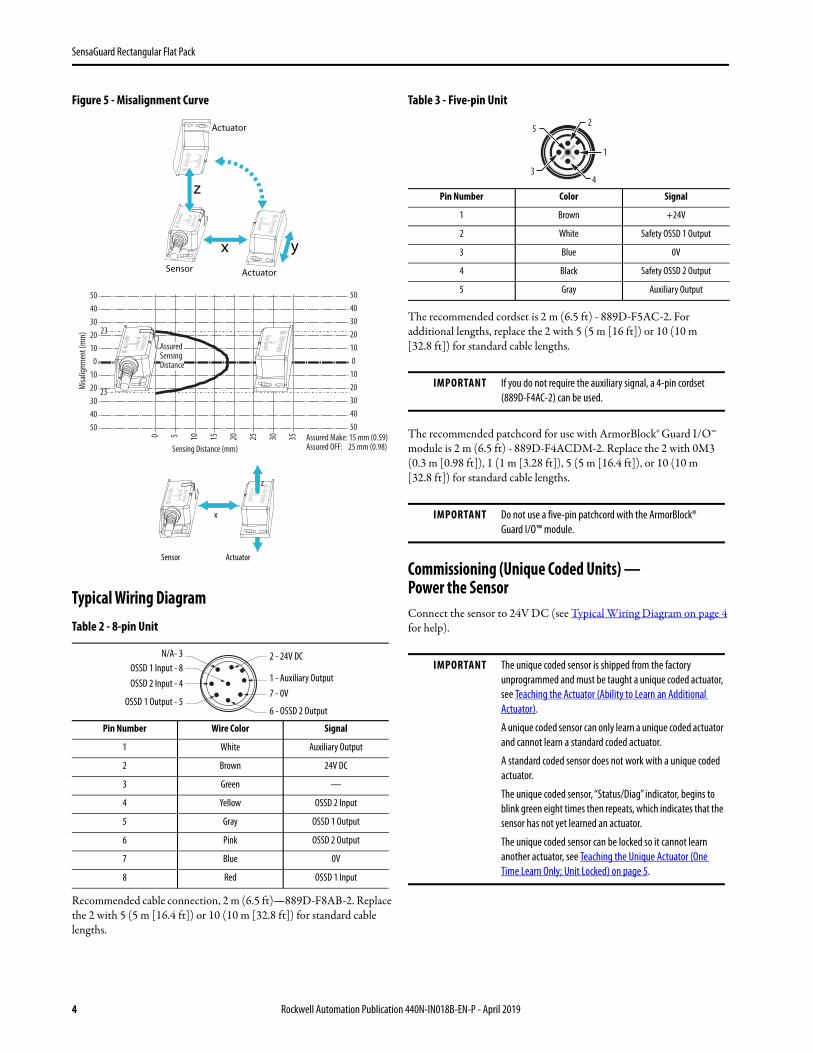
Figure 5 - Misalignment Curve
Typical Wiring Diagram
Recommended cable connection, 2 m (6.5 ft)—889D-F8AB-2. Replace the 2 with 5 (5 m [16.4 ft]) or 10 (10 m [32.8 ft]) for standard cable lengths.
Table 3 - Five-pin Unit
The recommended cordset is 2 m (6.5 ft) - 889D-F5AC-2. For additional lengths, replace the 2 with 5 (5 m [16 ft]) or 10 (10 m [32.8 ft]) for standard cable lengths.
The recommended patchcord for use with ArmorBlock® Guard I/O™ module is 2 m (6.5 ft) - 889D-F4ACDM-2. Replace the 2 with 0M3 (0.3 m [0.98 ft]), 1 (1 m [3.28 ft]), 5 (5 m [16.4 ft]), or 10 (10 m [32.8 ft]) for standard cable lengths.
Commissioning (Unique Coded Units) — Power the SensorConnect the sensor to 24V DC (see Typical Wiring Diagram on page 4 for help).Table 2 - 8-pin Unit
Pin Number Wire Color Signal
1 White Auxiliary Output
2 Brown 24V DC
3 Green —
4 Yellow OSSD 2 Input
5 Gray OSSD 1 Output
6 Pink OSSD 2 Output
7 Blue 0V
8 Red OSSD 1 Input
x
z
ySensor Actuator
Actuator
5 10 15 20 25 30 35
Sensing Distance (mm)
0
23
23
504030
2030
01020
10
4050
504030
2030
01020
10
4050
Misa
lignm
ent (
mm
)
AssuredSensingDistance
Assured Make: 15 mm (0.59)Assured OFF: 25 mm (0.98)
x
Sensor Actuator
zzz
N/A- 3OSSD 1 Input - 8OSSD 2 Input - 4
OSSD 1 Output - 5
2 - 24V DC
1 - Auxiliary Output7 - 0V
6 - OSSD 2 Output
Pin Number Color Signal
1 Brown +24V
2 White Safety OSSD 1 Output
3 Blue 0V
4 Black Safety OSSD 2 Output
5 Gray Auxiliary Output
IMPORTANT If you do not require the auxiliary signal, a 4-pin cordset (889D-F4AC-2) can be used.
IMPORTANT Do not use a five-pin patchcord with the ArmorBlock® Guard I/O™ module.
IMPORTANT The unique coded sensor is shipped from the factory unprogrammed and must be taught a unique coded actuator, see Teaching the Actuator (Ability to Learn an Additional Actuator).
A unique coded sensor can only learn a unique coded actuator and cannot learn a standard coded actuator.
A standard coded sensor does not work with a unique coded actuator.
The unique coded sensor, “Status/Diag” indicator, begins to blink green eight times then repeats, which indicates that the sensor has not yet learned an actuator.
The unique coded sensor can be locked so it cannot learn another actuator, see Teaching the Unique Actuator (One Time Learn Only; Unit Locked) on page 5.
5
43
1
2
4 Rockwell Automation Publication 440N-IN018B-EN-P - April 2019

SensaGuard Rectangular Flat Pack
Teaching the Actuator (Ability to Learn an Additional Actuator)
1. Power up the sensor and bring an actuator into the sensing range.
2. Leave the actuator in the sensing field for a minimum of two minutes.
3. Learn is complete.
The sensor automatically starts the learning process as soon as an actuator is brought into the sensing range.
Learning Sequence
Teaching the Unique Actuator (One Time Learn Only; Unit Locked)
Initially Teaching in the Actuator
The sensor automatically starts the learning process as soon as an actuator is brought into the sensing range.
Learning Sequence
Learning a New Actuator (Unique Coded Actuator Only)To learn a replacement actuator, bring the actuator to be taught into the sensing range of the safety switch.
The learn sequence is the same as the sequence for teaching the actuator (ability to learn an additional actuator).
A sensor cannot relearn a previously learned actuator or a standard SensaGuard actuator.
The sensor only recognizes the most recently learned actuator.
Unique Coded DiagnosticError codes for learning process. Power cycle to clear fault.
Figure 6 - OSSD Test Pulses
Individual PulsesTest pulses appear on each OSSD output. These pulses are approximately every 45 ms. The times that are shown are approximate and depend on the processing of the safety-related status.
IMPORTANT The sensor can learn a new actuator up to eight times. The Status/Diag indicator blinks the number of actuators left that a sensor can learn.
1. Target present Status/Diag indicator blinking green 2 Hz rate (15 s)
2. Verifying actuator
Status/Diag indicator blinking green/red 1 Hz rate (15 s)
3. Program sensor Status/Diag indicator blinking green/red 2 Hz rate (15 s)
4. Program complete
Status/Diag indicator blinking green 2 Hz rate (number of learns remaining) (15 s)
5. Ready state Status/Diag indicator solid green
6. Learn is complete
1. Target present Status/Diag indicator blinking green 2 Hz rate (15 s)
2. Verifying actuator Status/Diag indicator blinking green/red 1 Hz rate (15 s)
3. Program sensor Status/Diag indicator blinking green/red 2 Hz rate (15 s)
4. Program locking Status/Diag indicator blinking green 2 Hz rate (number of learns remaining) (15 s)
5. Remove the actuator from the sensing field
Status/Diag indicator changes to solid red
6. Replace the actuator back into the sensing field
Status/Diag indicator continues blinking green 2 Hz rate (number of learns remaining), this action triggers the lock function.
7. Ready state Status/Diag indicator solid green
8. Learn is complete Sensor is locked and cannot learn another actuator.
Status/Diag Indicator—Flashes (2 Hz) Error Code
Green OSSD inputs not valid
Red-Red-Red-Green Cannot learn a standard SensaGuard actuator
Red-Red-Red-Green-Green Actuator already learned
Red-Red-Red-Green-Green-Green Bad RFID; Target that is moved out of range
Red-Red-Red-Green-Green-Green-Green Exceeded learning eight actuators
Red-Red-Red-Green-Green-Green-Green-Green Unit locked: Cannot learn another actuator
Time (µs)
Periodicity
Pink Wire
Gray Wire
450 µs0
0 20 45 Time (ms)
Rockwell Automation Publication 440N-IN018B-EN-P - April 2019 5

SensaGuard Rectangular Flat Pack
Figure 7 - Timing Diagram
0 ms 45ms 50 ms 55 ms
S11 S12
S21 S22 S34
A1 13S52
A2 14
23
24
33 41
34 42
MSR127TP440R-N23132
0 ms 360 ms 378 ms 396 ms
+24V DC
SensaGuard Sensor
Unit 1SensaGuard Sensor
Unit 2
SensaGuard Sensor
Unit 3
SensaGuard Actuator SensaGuard Actuator SensaGuard Actuator
Response Time: Safety Outputs Turn OFFInitial Conditions: All actuators are in sensing distance.
Actuator 1 is moved out of sensing range.
24V Ground
Sensor 1 OSSD outputs (gray andpink) turn OFF. Sensor 1 indicatorturns solid red.
Sensor 2 OSSD outputs (gray andpink) turn OFF. Sensor 2 indicatorflashes green.
Sensor 3 OSSD outputs (gray andpink) turn OFF. Sensor 3 indicatorflashes green.
Response Time: Safety Outputs Turn ONInitial Conditions: Actuator1 is out of sensing range. Sensor 1 indicator is solid red. Actuators 2 and 3 are in sensing range. Sensor 2 and 3 indicators flash green.
Actuator 1 is moved into sensing range.
Sensor 2 OSSD inputs (red andyellow) transition to 24V DC from Sensor 1 OSSD outputs. Sensor 1 indicator turns solid green.
Sensor 3 OSSD inputs (red andyellow) transition to 24V DC from Sensor 2 OSSD outputs. Sensor 2 indicator turns solid green.
Sensor 3 OSSD outputs (gray andpink) are energized. Sensor 3 indicator turns solidgreen.
Yellow
Red
Brown
Pink
Gray
Blue
Yellow
Red
Brown
Pink
Gray
Blue
Yellow
Red
Brown
Pink
Gray
Blue
6 Rockwell Automation Publication 440N-IN018B-EN-P - April 2019

SensaGuard Rectangular Flat Pack
TroubleshootingFigure 8 - Series Circuit
Actu
ator
4
YellowRedBrown
PinkGray
Blue
Switc
h 4
Actu
ator
3
Switc
h 3
Actu
ator
2
Switc
h 2
Actu
ator
1
Switc
h 1
White
Actu
ator
5
YellowRedBrown
PinkGray
Switc
h 5
White
YellowRedBrown
PinkGray
White
BlueBlue
YellowRedBrown
PinkGray
White
Blue
YellowRedBrown
PinkGrayBlue
White
OSSD
s are
OFF
.Ac
tuat
or 5
is in
the s
ensin
g ran
ge.
Switc
h 5 is
func
tioni
ng pr
oper
ly.OS
SD in
puts
are 0
V.OS
SDs a
re de
-ene
rgize
d to 0
V.Gr
een i
ndica
tor f
lashe
s to
indica
te th
at O
SSD
input
s are
not
Actu
ator
4 is
in th
e sen
sing r
ange
.Sw
itch 4
is fu
nctio
ning p
rope
rly.
OSSD
inpu
ts ar
e 0V.
OSSD
s are
de-e
nerg
ized t
o 0V.
Gree
n ind
icato
r flas
hes t
oind
icate
that
OSS
D inp
uts a
re no
t
Actu
ator
3 is
in se
nsing
rang
e.Sw
itch 3
has a
faul
t.Se
e Diag
nosti
c tab
le —
red
indica
tor f
lashe
s.
Actu
ator
2 is
in se
nsing
rang
e.Sw
itch 2
is fu
nctio
ning p
rope
rly.
OSSD
s are
ener
gized
to 24
V.Gr
een i
ndica
tor is
ON.
Actu
ator
1 is
in se
nsin
g ran
ge.
Switc
h 1 is
func
tionin
g pro
perly
.OS
SDs a
re en
ergiz
ed to
24V.
Gree
n ind
icato
r is O
N.
Powe
r Su
pply
1606
-XL1
20D
Powe
r Sup
ply
24V G
roun
d
+24
V DC
+24
V+
24V
+24
V+
24V
+0V
+0V
+0V
+0V
+0V
+0V
Rockwell Automation Publication 440N-IN018B-EN-P - April 2019 7

SensaGuard Rectangular Flat Pack
Application Wiring ExamplesFigure 9 - Wiring to MSR127 Safety Relay
IMPORTANT The light curtain must be last (the furthest from MSR127).
126
5
3
7
3
S11 S12
S21S22 S34
A1 13S52
A2 14
23
24
33 41
34 42
MSR127RP440R-N231xx
K1
K2
S11 S12
S21S22 S34
A1 13S52
A2 14
23
24
33 41
34 42
MSR127RP440R-N231xx
K1
K2
S11 S12
S21S22 S34
A1 13S52
A2 14
23
24
33 41
34 42
MSR127RP440R-N231xx
K1
K2
S11 S12
S21S22 S34
A1 13S52
A2 14
23
24
33 41
34 42
MSR127TP440R-N231xx
K1
K2
K1 K2K1 K2
K1 K2 K1 K2
Sensor Actuator
YellowRed
Brown
Pink
Gray
SensaGuard Sensor Unit 1
+24V
Reset
MSR127RP with one sensor, monitored manual reset, drives 100S or 700S safety relays.
24V Ground
Blue
Sensor Actuator
YellowRed
Brown
Pink
Gray
SensaGuard Sensor Unit 1
+24V
MSR127RP with one sensor, automatic reset, drives 100S or 700S safety relays.
24V Ground
Blue
Sensor Actuator
YellowRed
Brown
Pink
Gray
SensaGuard Sensor Unit 1
+24V
Reset
MSR127RP with one sensor, monitored manual reset, drives the 100S or 700S safety relays.
24V Ground
Blue
Sensor Actuator
YellowRed
Brown
Pink
Gray
SensaGuard Sensor Unit 1
+24V
MSR127RP with two sensors and one 440L light curtain in series, monitored manual reset, drives the 100S or 700S safety relays.
24V Ground
Blue
Sensor Actuator
SensaGuard Sensor Unit 2
Sensor Actuator
YellowRed
Brown
Pink
Gray
SensaGuard Sensor Unit 2Blue
YellowRed
Brown
Pink
GrayBlue
Reset
Pink
440L GuardShield
Gray
ReceiverBrown
Transmitter
Blue
Green Blue
Brown
8 Rockwell Automation Publication 440N-IN018B-EN-P - April 2019

SensaGuard Rectangular Flat Pack
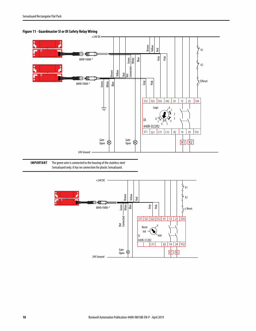
Figure 10 - Guardmaster® SI or DI Safety Relay Wiring
A1
S11 S21
S12S22S32
L11 Y32L12
13
14
S42 23
24
S34
A2
DI440R-D22R2
0 123
4567
8
A1S11 S21 S12S22
L11 Y32
13
14
23
24
S34
A2
SI440R-S12R2
0
MMAM
K1 K2
K1 K2
K1
K2
K1
K2
Blac
k
Reset
Brow
n
Whit
eGray
+24V DC
Blue889D-F5AC-5
Gate Open
Brow
nGr
ay
Blue
Blac
k
Whi
te
Gate Open
24V Ground
889D-F5AC-5
Blac
k
Reset
Brow
n
Whi
teGray
+24V DC
Blue889D-F5AC-5
Gate Open
24V Ground
Reset
Logic
Rockwell Automation Publication 440N-IN018B-EN-P - April 2019 9
SensaGuard Rectangular Flat Pack
Figure 11 - Guardmaster SI or DI Safety Relay Wiring
IMPORTANT The green wire is connected to the housing of the stainless steel SensaGuard only; it has no connection for plastic SensaGuard.
K1
K2
A1
S11 S21
S12 S22 S32
L11 Y32L12
13
14
S42 23
24
S34
A2
DI
440R-D22R2
01
23
456
78
K1 K2
Gree
n
Reset
Brow
n
Whi
te Gray
+24V DC
Blue889D-F8AB-*
Gate Open
Brow
n
Gray
Blue
Yello
w
Whi
te
Gate Open
24V Ground
889D-F8AB-*
Logic
Gree
n
Red
Pink
Yello
w
Red
Pink
Not
Conn
ecte
d
K1
K2
A1S11 S21 S12S22
L11 Y32
13
14
23
24
S34
A2
SI440R-S12R2
0
MMAM
K1 K2
Yello
w
Brow
nW
hite
Gray
+24V DC
Blue889D-F8AB-*
Gate Open
24V Ground
Reset
Reset
Gree
n
Red
Pink
Not
Conn
ecte
d
10 Rockwell Automation Publication 440N-IN018B-EN-P - April 2019

SensaGuard Rectangular Flat Pack
Figure 12 - CR30 Software Configurable Relay Wiring
K1
K2
K1 K2
05CR30 440C-CR30-22BBB
020100 03 04
A1 15 20 2116
06
18A2
07
19
08 10 11
12 13 14
09
17
Gree
n
Safety Reset
Brow
nW
hite
Gray
+24V DC
Blue889D-F8AB-5
Gate Open
Brow
nGr
ay
Blue
Yello
w
Whi
teGate Open
24V Ground
889D-F5AC-5
Red
Pink
Blac
k
100S Contactors or 700S or 700HPS Relays
Not
Conn
ecte
d
Rockwell Automation Publication 440N-IN018B-EN-P - April 2019 11

SensaGuard Rectangular Flat Pack
Figure 13 - 1734 POINT Guard I/O™ Wiring
889D-F5AC-5
K1
K2
1734-IB8S1734-AENT 1734-OB8S
I0 I1
I2
T0
I3
T1
COM COM
I4 I5
I6
T2
I7
T3M
COM COM
0 1
2
6
3
7
4 5
O0 O1
O2 O3
COM COM
O4 O5
O6 O7
COM COM
COM COM COM COM
889D-F8AB-5
K1K2
Gree
n
Safety Reset
Brow
nW
hite
Gray
+24V DC
Blue
Gate Open
Brow
nGr
ayBl
ue
Yello
w
Whit
eGate Open
24V Ground
Red
Pink
Blac
k
100S Contactors or 700S or 700HPS Relays
EtherNet/IP
100S Contactors or 700S or 700HPS Relays
Not
Conn
ecte
d
12 Rockwell Automation Publication 440N-IN018B-EN-P - April 2019

SensaGuard Rectangular Flat Pack
Figure 14 - 1732DS/ES ArmorBlock® Guard Safety I/O Wiring
889D-F4UCDM-5
OSSD
OSSD
K1
K2
889D-F8AB-5
A E
B F
D H
C G
1
2
4
3
12 3
4
1 T12 I13 C4 I05 T0
1 T12 I13 C4 I05 T0
1 T12 I13 C4 I05 T0
1 T12 I13 C4 I05 T0
1 T12 I13 C4 I05 T0
1 T12 I13 C4 I05 T0
X100 X1X10
2 O11+24
3 C4 O05 C
2 O11+24
3 C4 O05 C
35
4
2 1
35
4
2 1
K1
K2
871A-TS5-DM1
871A-TS5-DM1
1732ES-IB12XOB4
The screen shots below show the input and output configuration for the 1732ES.
Gree
n
Whit
e
+24V DC
Brow
n GrayBlue
Yello
wRe
d
Patchcord
Safety Reset
100S Contactors or 700S or 700HPS Relays
24V Ground
Cordset
Pink
Power
Ground
Ethernet871A-TS5-DM15-pin Field Attachable Connector
Power
Not Connected
Rockwell Automation Publication 440N-IN018B-EN-P - April 2019 13

SensaGuard Rectangular Flat Pack
Recommended Safety Control InterfacesRecommended relays are GSR DI, GSR DIS, GSR SI, CR30, MSR126, MSR127, MSR131, MSR138, SmartGuard™ controller, 1791DS/ES CompactBlock™ Guard I/O™, 1732DS/ES ArmorBlock Guard I/O, 1734 POINT Guard I/O.
MaintenanceEvery MonthCheck the correct operation of the switching circuit. Also check for signs of abuse or interference. Inspect the switch casing for damage.
Every Five YearsCheck the correct operation of the switching circuit. Also check for signs of abuse or interference. Inspect the switch casing for damage. The switch must be disconnected and readjusted.
RepairIf there is any malfunction or damage, no attempts at repair can be made. The unit must be replaced before machine operation is allowed.
Declaration of ConformityThis declaration is to declare that the products that are shown in this document conform with the Essential Health and Safety Requirement (EHSRs) of the European Machinery Directive 2006/42/EC.
Visit https://www.rockwellautomation.com/global/certification/overview.page
14 Rockwell Automation Publication 440N-IN018B-EN-P - April 2019

SensaGuard Rectangular Flat Pack
Notes:
Rockwell Automation Publication 440N-IN018B-EN-P - April 2019 15

Rockwell Automation SupportUse the following resources to access support information.
Documentation FeedbackYour comments will help us serve your documentation needs better. If you have any suggestions on how to improve this document, complete the How Are We Doing? form at http://literature.rockwellautomation.com/idc/groups/literature/documents/du/ra-du002_-en-e.pdf.
Technical Support Center Knowledgebase Articles, How-to Videos, FAQs, Chat, User Forums, and Product Notification Updates. https://rockwellautomation.custhelp.com/
Local Technical Support Phone Numbers Locate the phone number for your country. http://www.rockwellautomation.com/global/support/get-support-now.page
Direct Dial Codes Find the Direct Dial Code for your product. Use the code to route your call directly to a technical support engineer. http://www.rockwellautomation.com/global/support/direct-dial.page
Literature Library Installation Instructions, Manuals, Brochures, and Technical Data. http://www.rockwellautomation.com/global/literature-library/overview.page
Product Compatibility and Download Center (PCDC)
Get help determining how products interact, check features and capabilities, and find associated firmware. http://www.rockwellautomation.com/global/support/pcdc.page
Waste Electrical and Electronic Equipment (WEEE)
At the end of life, this equipment should be collected separately from any unsorted municipal waste.
Allen-Bradley, ArmorBlock, Guard I/O, Guardmaster, GuardShield, POINT Guard I/O, SensaGuard, and Rockwell Automation are trademarks of Rockwell Automation, Inc.
Trademarks not belonging to Rockwell Automation are property of their respective companies.
Rockwell Otomasyon Ticaret A.Ş., Kar Plaza İş Merkezi E Blok Kat:6 34752 İçerenköy, İstanbul, Tel: +90 (216) 5698400
Rockwell Automation maintains current product environmental information on its website athttp://www.rockwellautomation.com/rockwellautomation/about-us/sustainability-ethics/product-environmental-compliance.page.
Publication 440N-IN018B-EN-P - April 2019 PN-474220Supersedes Publication 440N-IN018A-EN-P - May 2018 10003829146 Ver 01
Copyright © 2019 Rockwell Automation, Inc. All rights reserved. Printed in the U.S.A.


![TECHNICAL INFORMATION TD-00036d2xunoxnk3vwmv.cloudfront.net/uploads/TD-00036K.pdf[9] IEC 60153-3: 1964, “Hollow metallic waveguides, Part 3: Relevant specifications for flat rectangular](https://static.fdocuments.in/doc/165x107/611c26b42a693235690a3389/technical-information-td-9-iec-60153-3-1964-aoehollow-metallic-waveguides.jpg)