Senior Thesis Proposal - Pennsylvania State University · Senior Thesis Proposal . ... related to...
13
THE PENNSYLVANIA STATE UNIVERSITY APPLIED RESEARCH LABORATORY BUILDING V STATE COLLEGE, PA Senior Thesis Proposal Eric M. Foster Architectural Engineering Structural Option Advisor: Dr. Linda M. Hanagan
Transcript of Senior Thesis Proposal - Pennsylvania State University · Senior Thesis Proposal . ... related to...

THE PENNSYLVANIA STATE UNIVERSITY
APPLIED RESEARCH LABORATORY
BUILDING V
STATE COLLEGE, PA
Senior Thesis Proposal
Eric M. Foster Architectural Engineering
Structural Option
Advisor: Dr. Linda M. Hanagan

Eric M. Foster Applied Research Laboratory - Building V Structural Option State College, Pa Advisor: Dr. Linda M. Hanagan December 18, 2008
THESIS PROPOSAL
PAGE 2 OF 2
-- TABLE OF CONTENTS --
-- TABLE OF CONTENTS -- ...................................................................................................................................... 2 -- EXECUTIVE SUMMARY -- .................................................................................................................................. 3 -- BUILDING INTRODUCTION -- ........................................................................................................................... 4 -- STRUCTURAL SYSTEM -- ................................................................................................................................... 5
FOUNDATION(S): .................................................................................................................................... 5
COLUMNS: ................................................................................................................................................ 6
FLOOR SYSTEM: ..................................................................................................................................... 7
ROOF SYSTEM: ....................................................................................................................................... 7
LATERAL SYSTEM: ............................................................................................................................... 8
-- PROBLEM STATEMENT -- ................................................................................................................................. 9 -- PROPOSED SOLUTION – ..................................................................................................................................... 9 --BREADTH STUDIES -- ........................................................................................................................................ 10
ARCHITECTURE: .................................................................................................................................. 10
BLAST PROTECTION: .......................................................................................................................... 10
-- TASKS & PROPOSED SCHEDULE -- .............................................................................................................. 11 TASKS & TOOLS: .................................................................................................................................... 11
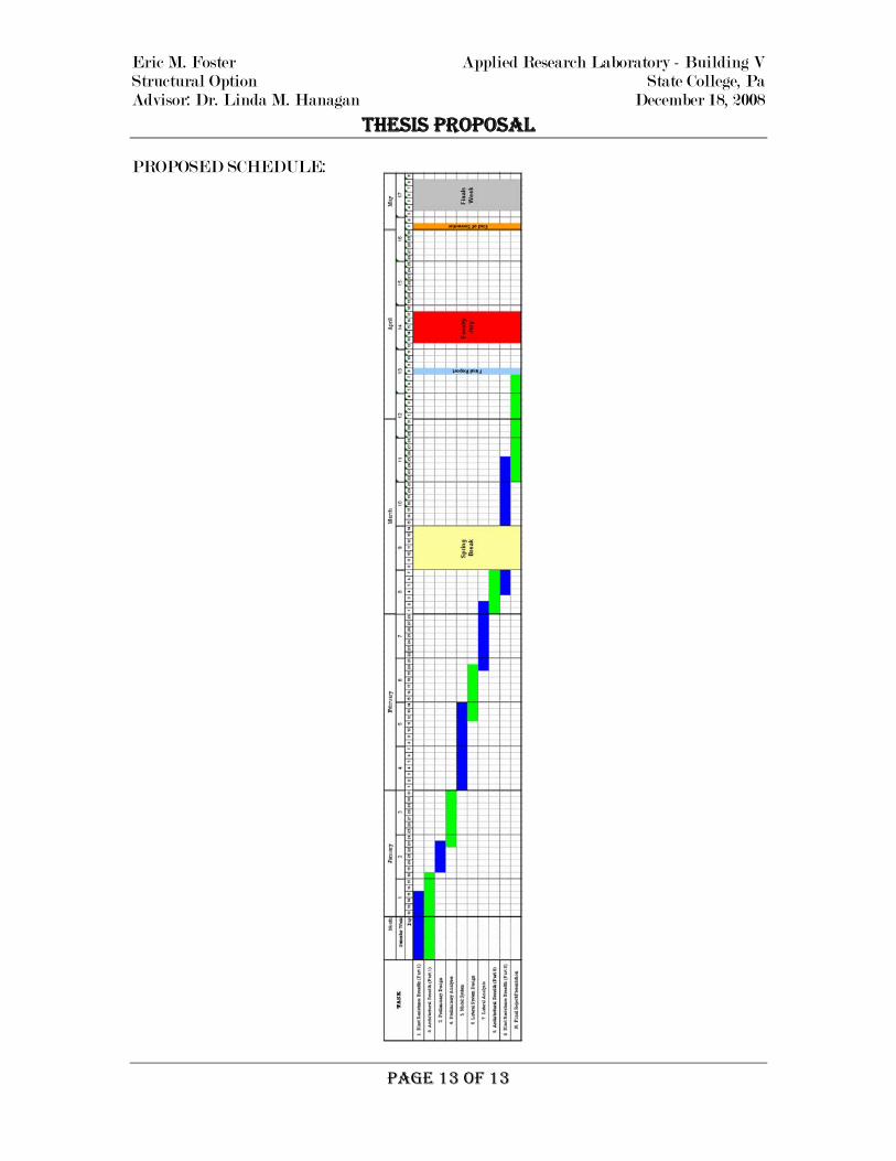
PROPOSED SCHEDULE: ..................................................................................................................... 13

Eric M. Foster Applied Research Laboratory - Building V Structural Option State College, Pa Advisor: Dr. Linda M. Hanagan December 18, 2008
THESIS PROPOSAL
PAGE 3 OF 3
-- EXECUTIVE SUMMARY --
The Applied Research Laboratory’s Building V (Bldg. Five) is an $18 million, 3-
story office building and research facility being constructed in State College, Pa. The
121,000 square foot structure will function as a specialized research facility for a branch
of the U.S. Department of Defense. This high-security infrastructure will include lab
and office area on all but the third floor level, which was designated mainly for office
space. Building V will be constructed using different precast systems, including the
twenty-eight shear walls that make up the main lateral force resisting system. Building
V is also being designed to achieve a LEED certified Gold rating.
Upon request of the tenant, necessary actions were taken to allow for the addition
of several floors needed for office space. The new structure will be designed with 4
additional levels of office space, totaling 7 stories overall. With the addition of these
levels, the structure shall be redesigned using steel framing as the main lateral and
gravity systems. Research and advice taken from a co-working engineer suggests braced
frames be used to maximize the strength of the lateral system. Additionally, a concrete
core shall also be considered to aide with torsion and drift criteria. Other structural
issues, like the green roofs introduced, will be addressed during design phase to avoid any
unnecessary strength calculations.
Converting the precast structure to a taller, steel framed structure will also
stimulate changes to the envelope and overall perspective of the new edifice. An
architectural breadth will be conducted to facilitate changes with overall architectural
layout and aesthetics. The aesthetics portion of the architectural breadth is directly
related to design criteria set forth by the second breadth topic: blast resistance. This
breadth study will include research concerning blast resistant systems and progressive
failure in the event of an attack. Due to the increased level of security required by the
occupant, advanced research on blast resistant systems could prove efficient and thus will
be investigated.
This proposal details the tasks to be completed during the second part of the senior
thesis project along with a schedule of those tasks broken down over a weekly course of
the semester.

Eric M. Foster Applied Research Laboratory - Building V Structural Option State College, Pa Advisor: Dr. Linda M. Hanagan December 18, 2008
THESIS PROPOSAL
-- BUILDING INTRODUCTION --
Applied Research Laboratory, Building V will be used as a highly classified research facility, specializing in the development and testing of underwater weapons for the U.S. Department of Defense. Located on Science Park Road in State College, Pa, the structure will be a 3-story, 42’ low-rise building with typical 35’ square bays broken into areas classified as office, light industrial, and warehouse totaling nearly 120,000 square feet. The first floor of the Building V will consist mainly of ‘closed’ lab area, along with technician offices, locker rooms and special test areas. The second floor will include office space, another lab area, computer lab, student room and a room designated to SCIF (Sensitive Compartmented Information Facility), while the third floor will be devoted mostly to office space. The entire building will be constructed of precast systems, including: columns, prestressed beams & diaphragms, and walls. Building V utilizes a 16’-0” floor-to-floor height for the ground level, while the remaining two floors have a typical floor-to-floor height of 12’-0”. Lateral loads applied to the structure will be collectively distributed throughout the building to specially designed shear walls.
PAGE 4 OF 4

Eric M. Foster Applied Research Laboratory - Building V Structural Option State College, Pa Advisor: Dr. Linda M. Hanagan December 18, 2008
THESIS PROPOSAL
-- STRUCTURAL SYSTEM --
As stated above, ARL Building V is a total precast building. The following are detailed explanations of the individual precast members and systems. FOUNDATION(S):
The foundation system(s) being implemented consists of typical cast-in-place (CIP) strip and pad footings, as well as a standard CIP slab-on-grade. Fifteen inch deep strip footings ranging from 3’-3” to 6’-6” wide are used along the perimeter of the structure. These footings help distribute wall panel loads into the ground. Additionally, the East walls strip footing of the structure will also be used as a part of the underground water cistern that will be used to collect treatable storm water runoff for reuse. Spread (or Pad) footings will be used throughout the interior portion of the building and will be used to pick up loads from columns and stair-towers. Pads used under columns vary in size from 12’ square to 14’-5 square, while pads under the four typical stair-towers are 12’-0 x 25’-6. All pad footings are 2 foot thick unless noted otherwise. A five inch thick slab-on-grade reinforced with W4.0 x W4.0 WWF will complete the foundation system(s) and will be used as the ground floor level of the building. See Figures #1 and #2 below for a plan view of the foundation systems and proposed cistern detail, respectively. Please note, the width of the cistern was unavailable at this time.
PAGE 5 OF 5

Eric M. Foster Applied Research Laboratory - Building V Structural Option State College, Pa Advisor: Dr. Linda M. Hanagan December 18, 2008
THESIS PROPOSAL
COLUMNS: The vertical supporting members for the entire structure are reinforced, precast concrete columns. All columns are 24” x 24” square columns with four (4) #11 longitudinal reinforcing bars and #4 stirrups spaced accordingly (See Figure #3). Columns will be cast for lengths up to 42 feet. Each column will contain haunches and haunch reinforcing (Figure #4) cast monolithically at each floor level, and in the required position for beam bearing and load transfer. The columns are spaced on a 35’-0 x 35’-0 typical bay grid and are connected to the pad footings with four (4) 1 ¼” dia. ASTM A193 threaded rods. See Figure #5 for column grid layout.
PAGE 6 OF 6

Eric M. Foster Applied Research Laboratory - Building V Structural Option State College, Pa Advisor: Dr. Linda M. Hanagan December 18, 2008
THESIS PROPOSAL FLOOR SYSTEM: As previously stated, the 1st Floor (or Ground Level) floor system is a 5” thick slab-on-grade with W4.0 x W4.0 WWF reinforcing. The remaining floor levels are constructed of precast, prestressed hollow-core flat slabs. The 2nd Floor Level will consist of 12 inch and the 3rd Floor Level will be comprised of 10 inch hollow-core flat slabs, each with six (6) 7-wire, ½” SP (special) 270 ksi low-relaxation prestressing strands and a typical 2” topping. Some of the hollow-core floor system clear spans are nearly 33’-0, with individual panels running in an East-West direction. Furthermore, the hollow-core slabs are supported by one of two methods. If the floor slab is to bear at an exterior wall panel location, the wall panel will be designed with a pocket used for the plank to bear on. For interior bay supports, the hollow-core slabs will be supported by precast, prestressed concrete inverted-tee (IT) beams resting on column corbels. IT beams for the 2nd Floor were designed to be 28” deep, while 3rd Floor beams are 20” deep due to dissimilar live loads.
ROOF SYSTEM: The roofing system for ARL Building V’s main roof will be constructed by means of similar materials used in erecting floors two and three. The main roof will consist of 8” hollow-core flat slabs with (7) 7-wire, ½” SP, 270 ksi low-relaxation strands supported by 18” deep inverted-tee beams. The low roof, located in the rear storage area of the building, will be constructed of 10’-9 wide x 24” deep precast concrete double-tees (See Figure #6). In addition, each roof will receive a layer of 4” tapered rigid insulation and a 60 mil EPDM roofing membrane rather than a 2” topping which is not needed on the roof.
PAGE 7 OF 7

Eric M. Foster Applied Research Laboratory - Building V Structural Option State College, Pa Advisor: Dr. Linda M. Hanagan December 18, 2008
THESIS PROPOSAL
LATERAL SYSTEM: One of the key design issues of a total precast structure is the make up of the lateral force resisting system. ARL Building V is no different; its lateral system was designed using a compilation of precast shear walls positioned around the perimeter and throughout the building. Each of the 28 shear walls are constructed with several different thicknesses of insulated and non-insulated precast panels. Exterior wall panels (all insulated) acting as shear walls in the N-S direction are 12 ½” thick, while E-W direction walls are 9 ½” thick. The 12 ½” panels consist of 2 ½” of rigid insulation sandwiched between a 2 ½” (ext. face) & 7 ½” (int. face) concrete slab, while the 9 ½” differs only with a 4 ½” (int. face) slab. Shear walls located on the interior of the structure and around stair-towers are 9” thick and non-insulated. Due to the fact that every panel is individually erected, specially designed connections are required for each piece. A breakdown of the lateral loads and how they are distributed throughout the panels is available in Tech Report III. Figure #7 below illustrates the layout of the shear walls; each represented by a solid line with a SW designation.
PAGE 8 OF 8

Eric M. Foster Applied Research Laboratory - Building V Structural Option State College, Pa Advisor: Dr. Linda M. Hanagan December 18, 2008
THESIS PROPOSAL
PAGE 9 OF 9
-- PROBLEM STATEMENT --
Having performed several of the actual designs used for ARL’s Building V and the required technical reports for this senior thesis project proved that the structural system utilized in the existing building is adequate of resisting the calculated gravity, wind, and seismic loads.
For the purpose of fulfilling senior thesis project requirements, a petition will assumed to be deemed granted for the addition of several stories needed for office space. The acquired permission was issued with the understanding and intent that the redesign takes on a more architectural appeal than the existing precast envelope.
Negotiating height for aesthetics creates several area of concern. Because the tenant has requested the addition of several levels of office space, the use of precast for the entire building envelope could prove to be insufficient and uneconomical. A conversion of the existing precast concrete system to a braced steel framing system will also introduce architectural issues such as grid layout, core location, and façade aesthetics.
-- PROPOSED SOLUTION –
Due to the additional levels proposed for the structure, a redesign of the lateral system using steel braced frames as the main lateral resisting system shall be examined; with the possibility of an additional concrete core shear wall system to aide in accidental torsion and drift criterion. The lateral system will be modeled and analyzed using computer modeling programs such as ETAB and/or RAM in order to consider and determine the required locations of the steel braced frames and/or shear wall core. These situations will be carefully modeled to ensure proper design of Building V’s new structural system by limiting drift, torsion, and vibration design factors for optimal occupant comfort. Considerations of blast resistant structural members and façade panelization & glazing shall also be examined during the redesign of the lateral system. Because the structure will function as a highly classified federal research facility, initiative will be taken against the dire possibility of a terrorist attack occurring during operating hours. Research shall be conducted on all necessary information related to blast resistance & properties, design blast loading, and localized failure to ensure a feasible redesign. In addition to the aforementioned information, an architectural study will be conducted in order to allocate the proposed redesign. Using steel braced frames as the main lateral system may hinder the existing floor plan, thus altering the overall architectural layout and vision of the structure. However, these braced frames will try to be incorporated into the architectural aspect of the design by leaving them exposed in selected areas. The site is also limited in size, thus these issues will be researched in a collaborative effort to reduce the building footprint creating larger areas for impervious ground cover and parking.

Eric M. Foster Applied Research Laboratory - Building V Structural Option State College, Pa Advisor: Dr. Linda M. Hanagan December 18, 2008
THESIS PROPOSAL
PAGE 10 OF 10
--BREADTH STUDIES --
ARCHITECTURE: Introducing a completely different steel framing method for ARL’s Building V
will have ramifications to the existing floor plan and overall design. Great effort will be taken in order to maintain a majority of the existing layout spaces and areas, relocating areas as deemed necessary. In an attempt to minimize deflection and vibration concerns, the 35’x35’ typical bays will be considered and likely reduced to incorporate shallow floor plenums and stiffer diaphragms. Special interest will be devoted to floors 1 & 2 based on the amount of open lab space desired and the introduction of blast protection. Furthermore, removing the precast panel envelope around the perimeter lends itself to a variety of different façade and glazing finishes. The change induced on the exterior of the edifice due to the redesigned steel framing and glass curtain façade will be analyzed and incorporated in the appearance overhaul.
In addition, with the existing structure striving for a LEED Gold rating, it only seems fit to incorporate green roofs throughout the plan. Depending on the layout of the proposed structure, green roofs will try to be developed on lower floors. Placing the green roofs lower to the ground will be less critical during lateral loading, compared to being placed on upper levels where the weight of the roof could cause significant drift issues. BLAST PROTECTION:
As stated in the building introduction, Building V will function as a highly
classified research facility for development testing of underwater weapons. Such top secret information related to the government makes the site prone to foreign attacks. A depth study concerning blast resistant systems and progressive failure will be examined to gain a better understanding of this information, as well as its practicality. The exact detail of research and testing is being withheld due to security purposes; hence the study shall include blast resistant designs for both interior and exterior spaces. Interior explosions resulting from unknown testing conducted within working lab areas shall be considered and designed for mainly catastrophic failure of the entire structure. Similar to interior blast designs, the exterior perimeter of the structure will be developed to withstand a blast impact while minimizing the amount of damage to the structure. Special glazing designed for this reason shall be researched and analyzed in order to determine permissible designs.
Eric M. Foster Applied Research Laboratory - Building V Structural Option State College, Pa Advisor: Dr. Linda M. Hanagan December 18, 2008
THESIS PROPOSAL
PAGE 11 OF 11
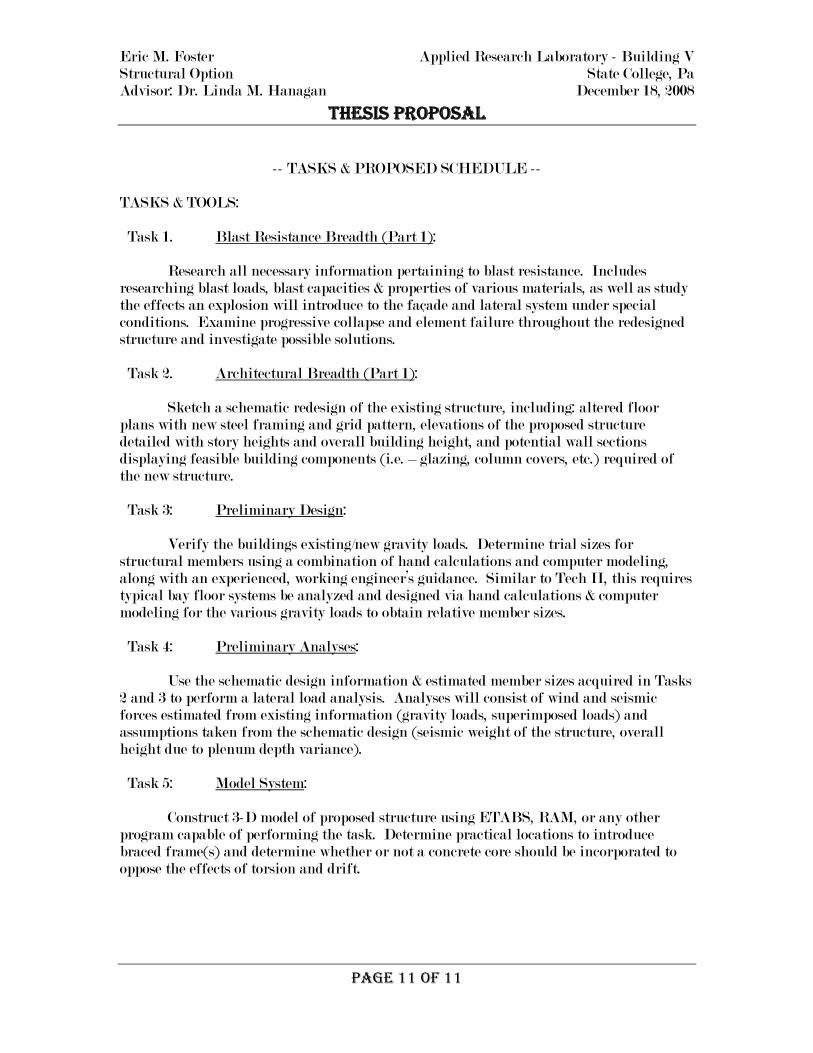
-- TASKS & PROPOSED SCHEDULE -- TASKS & TOOLS: Task 1. Blast Resistance Breadth (Part 1):
Research all necessary information pertaining to blast resistance. Includes researching blast loads, blast capacities & properties of various materials, as well as study the effects an explosion will introduce to the façade and lateral system under special conditions. Examine progressive collapse and element failure throughout the redesigned structure and investigate possible solutions. Task 2. Architectural Breadth (Part 1):
Sketch a schematic redesign of the existing structure, including: altered floor plans with new steel framing and grid pattern, elevations of the proposed structure detailed with story heights and overall building height, and potential wall sections displaying feasible building components (i.e. – glazing, column covers, etc.) required of the new structure. Task 3: Preliminary Design: Verify the buildings existing/new gravity loads. Determine trial sizes for structural members using a combination of hand calculations and computer modeling, along with an experienced, working engineer’s guidance. Similar to Tech II, this requires typical bay floor systems be analyzed and designed via hand calculations & computer modeling for the various gravity loads to obtain relative member sizes. Task 4: Preliminary Analyses: Use the schematic design information & estimated member sizes acquired in Tasks 2 and 3 to perform a lateral load analysis. Analyses will consist of wind and seismic forces estimated from existing information (gravity loads, superimposed loads) and assumptions taken from the schematic design (seismic weight of the structure, overall height due to plenum depth variance). Task 5: Model System: Construct 3-D model of proposed structure using ETABS, RAM, or any other program capable of performing the task. Determine practical locations to introduce braced frame(s) and determine whether or not a concrete core should be incorporated to oppose the effects of torsion and drift.

Eric M. Foster Applied Research Laboratory - Building V Structural Option State College, Pa Advisor: Dr. Linda M. Hanagan December 18, 2008
THESIS PROPOSAL
PAGE 12 OF 12
(TASKS & TOOLS cont.) Task 6: Lateral System Design: Perform any necessary adjustments to the structure found through computer based modeling and hand calculations to come up with a finalized lateral force resisting system design for the new structure; making sure all required braced frames are in their respective positions. Task 7: Lateral Analysis: The preliminary analysis performed in Task 4 should yield the controlling lateral load combination(s). The governing load combination(s) shall be reanalyzed similar to Tech III with the finalized system of Task 6 in order to determine how the lateral loads will be distributed throughout the building, and the amount of load each member is required to resist. Also, determine if the new structure will require the foundation system to be redesigned. Task 8: Architectural Breadth (Part 2): Research the essential LEED credits to establish Gold and Platinum ratings and determine whether or not feasible to press for a Platinum rating. Incorporate green roofs considered during structural design phase. Use research found in Task 1 to select blast resistant glazing and required column covers that will unify architectural redesign. Task 9: Blast Resistance Breadth (Part 2): Performing all necessary calculations for strength and sustainability prove the selected blast resistant components are practical. Task 10: Final Presentation: Conclude any results and final design problems which may have arose, organizing these results into a written final thesis report. A 10 minute presentation summarizing this report will be composed and presented to the faculty and jury of the Architectural Engineering Department.
Eric M. Foster Applied Research Laboratory - Building V Structural Option State College, Pa Advisor: Dr. Linda M. Hanagan December 18, 2008
T
HESIS PROPOSAL PROPOSED SCHEDULE:
PAGE 13 OF 13


![Christopher Kelly Senior Thesis Design Proposal · 2010-12-10 · Christopher Kelly Senior Thesis Design Proposal Final Report [Fall 2010] Analysis SALK HALL ADDITION The University](https://static.fdocuments.in/doc/165x107/5e9114fda9311f30b05dc2b1/christopher-kelly-senior-thesis-design-2010-12-10-christopher-kelly-senior-thesis.jpg)


![[REVISED SENIOR THESIS PROPOSAL] December 12, 2011 2011 · [REVISED SENIOR THESIS PROPOSAL] December 12, 2011 Biological Research Laboratory | 7 Analysis 2: BIM Implementation - Benefits](https://static.fdocuments.in/doc/165x107/5f5b1e417dc85d320a7ffbe3/revised-senior-thesis-proposal-december-12-2011-2011-revised-senior-thesis-proposal.jpg)


