Senior Design Final Report - University of Florida Senior Design Final Design Report April 21, 2009...
25
EEL4914 Senior Design Final Design Report April 21, 2009 Project Title: Integrated Car Anti-Theft System (ICATS) Team Name: SQAN Submitted by: Angelique Dawkins [email protected] Tyler Schlichter [email protected] Project Abstract: The goal of this project was to prevent vehicle theft through a car alarm system. The system has a user interface that allows the owner to arm and disarm the vehicle with a 4 digit code, and if in armed mode ultrasonic sensors will detect if someone has entered the car. An alarm will then sound, as well as notify the owner of the car via cell phone, and take pictures of the criminal.
Transcript of Senior Design Final Report - University of Florida Senior Design Final Design Report April 21, 2009...
EEL4914 Senior Design Final Design Report
April 21, 2009
Project Title: Integrated Car Anti-Theft System (ICATS) Team Name: SQAN
Submitted by: Angelique Dawkins [email protected]
Tyler Schlichter [email protected]
Project Abstract: The goal of this project was to prevent vehicle theft through a car alarm system. The system has a user interface that allows the owner to arm and disarm the vehicle with a 4 digit code, and if in armed mode ultrasonic sensors will detect if someone has entered the car. An alarm will then sound, as well as notify the owner of the car via cell phone, and take pictures of the criminal.
Table of Contents
Project Abstract:.......................................................................................................... 1 Table of Contents........................................................................................................ 2 List of Tables and Figures........................................................................................... 3 Project Features/Objectives ........................................................................................ 4 Analysis of Competitive Projects................................................................................ 5 Concept/Technologies................................................................................................. 6 Project Architecture .................................................................................................... 7 Flowcharts................................................................................................................... 8 Final Division of Labor............................................................................................... 9 Bill of Materials ........................................................................................................ 10 Gantt Chart................................................................................................................ 11 Appendices................................................................................................................ 12 Appendix A: PICBasic Code .............................................................................. 13 Appendix B: Camera Code ................................................................................. 24
List of Tables and Figures
Table 1: Division of Labor.................................................................................................. 9 Table 2: Bill of Materials.................................................................................................. 10 Figure 1: System Level Block Diagram.............................................................................. 7 Figure 2: User Interface Code Flowchart............................................................................ 8 Figure 3: Gantt Chart ........................................................................................................ 10

Project Features/Objectives
Arming and Disarming – The car owner will be able to arm or disarm the system through the LCD and keypad interface with a four digit code. While disarmed, none of the peripherals will be activated. In armed mode, the system will constantly check the A/D input from the sensor to detect a break-in.
Detecting car entry – Using an ultrasonic sensor to determine the presence of
someone in the vehicle. Because the user interface would be located in the door of the car and a person has to physically get into the car to trigger the alarm, this will allow the car owner to arm and disarm the system without setting the alarm off.
Alarm – The system will use a “quiet” alarm, one that will relay a message and be
clear and audible to whoever is in the immediate vicinity of the car, but will not disturb others who are far away.
Pictures – When the car alarm is activated, a camera located in the vehicle will
begin immediately snapping pictures of the interior. This can be used at a later time to identify the thief.
Cell phone interfacing – When the alarm is triggered, the system will send a text
to the user’s phone indicating that a break-in is occurring.
Powered independently of car circuitry – The entire system is run off of batteries that are independent of the car battery. This will ensure that the car battery is not drained and that tampering with the internal circuitry of the car will not affect the system.

Analysis of Competitive Projects
Due to the unique nature of this project, there is no other car alarm system that accomplishes the exact same goals as ICATS. In order to prevent vehicle detection, pricier car alarm systems that can be bought and integrated with the car allow the owner to monitor many aspects of the vehicle through remote, but these systems all have a specified range and will not work outside of that. For ICATS, while the system does not allow for remote monitoring in this way, if a break-in occurs the car owner will be notified via cell phone even outside a range of several miles. The following are some state-of-the-art car alarm systems:
Viper 5901 Responder LC3 SuperCode SST 2-Way Security and Remote Start System ($649.99): Comes with a portable remote with LCD screen, and has a 1 mile range. Lets the car owner know the current temperature inside the car, allows the owner to disable the alarm to only get alerts via remote, and displays alerts if anything happens to the car, all if the owner is within the 1 mile range.
Commando FM-870 Remote Car Starter, Car Alarm with 2-Way FM Pager ($169.99): This product comes with a portable remote with LCD screen, and allows the car owner to remote start the car, monitor car doors and the hood and trunk, and if the vehicle is experiencing any hard impacts. The system works if the remote is within the 2500 foot range.

Concept/Technologies
The main parts chosen for use in this project were an ultrasonic sensor, the PIC microprocessor, LCD and keypad for the user interface, camera, cell module, and the voice record chip. The sensor chosen for this project was the Ultrasonic Range Finder – Maxbotix LV-EZ0. This particular model was chosen because it had the widest cone of detection of the Maxbotix products, which was good for sensing people. While originally a vibration sensor was going to be used to sense window break-ins, the ultrasonic sensor would be able to cover any scenario where a car thief would actually enter a car. The cell module used in this project was the GM862 Cellular Quad Band Module. It has a wide range of capabilities that were useful for this project, including texting, making calls, and a GPS system. Because it is cell phone technology, it allows the entire system to be effective even if the car owner is miles away from the car since they will still receive text alerts. The ISD25120P chip was used to record messages to be played as the alarm. This was used as opposed to text-to-speech chips for ease of use in recording different messages and to have a realistic sounding voice as the alarm. The camera small enough to be placed and hidden in the car, and had the ability to take rapid pictures, as well as record video. For the user interface, a four line LCD and keypad were chosen. The larger LCD was needed to provide a more user-friendly interface and to have more space to display menus, while the keypad was needed to receive input for added security. The microprocessor chosen for the project was the 40 pin PIC18F4620 because of ease of programming, the wide array of functions it possessed, and the large number of pins which made it easier to control all peripherals from the same chip. It is able to be run anywhere from 2 to 5.5 V and possesses 36 I/O lines and a 10 bit A/D converter.
Project Architecture
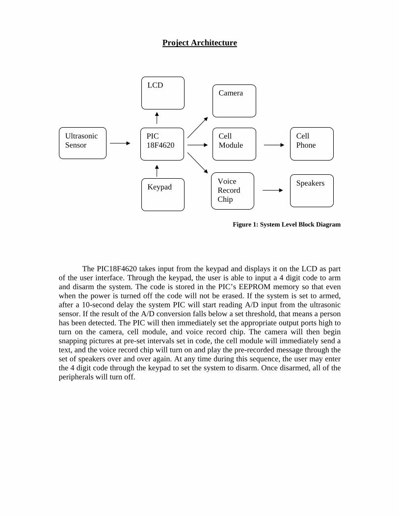
Figure 1: System Level Block Diagram
The PIC18F4620 takes input from the keypad and displays it on the LCD as part of the user interface. Through the keypad, the user is able to input a 4 digit code to arm and disarm the system. The code is stored in the PIC’s EEPROM memory so that even when the power is turned off the code will not be erased. If the system is set to armed, after a 10-second delay the system PIC will start reading A/D input from the ultrasonic sensor. If the result of the A/D conversion falls below a set threshold, that means a person has been detected. The PIC will then immediately set the appropriate output ports high to turn on the camera, cell module, and voice record chip. The camera will then begin snapping pictures at pre-set intervals set in code, the cell module will immediately send a text, and the voice record chip will turn on and play the pre-recorded message through the set of speakers over and over again. At any time during this sequence, the user may enter the 4 digit code through the keypad to set the system to disarm. Once disarmed, all of the peripherals will turn off.
Ultrasonic Sensor
PIC 18F4620
Camera
Cell Module
Cell Phone
LCD
Keypad SpeakersVoice Record Chip
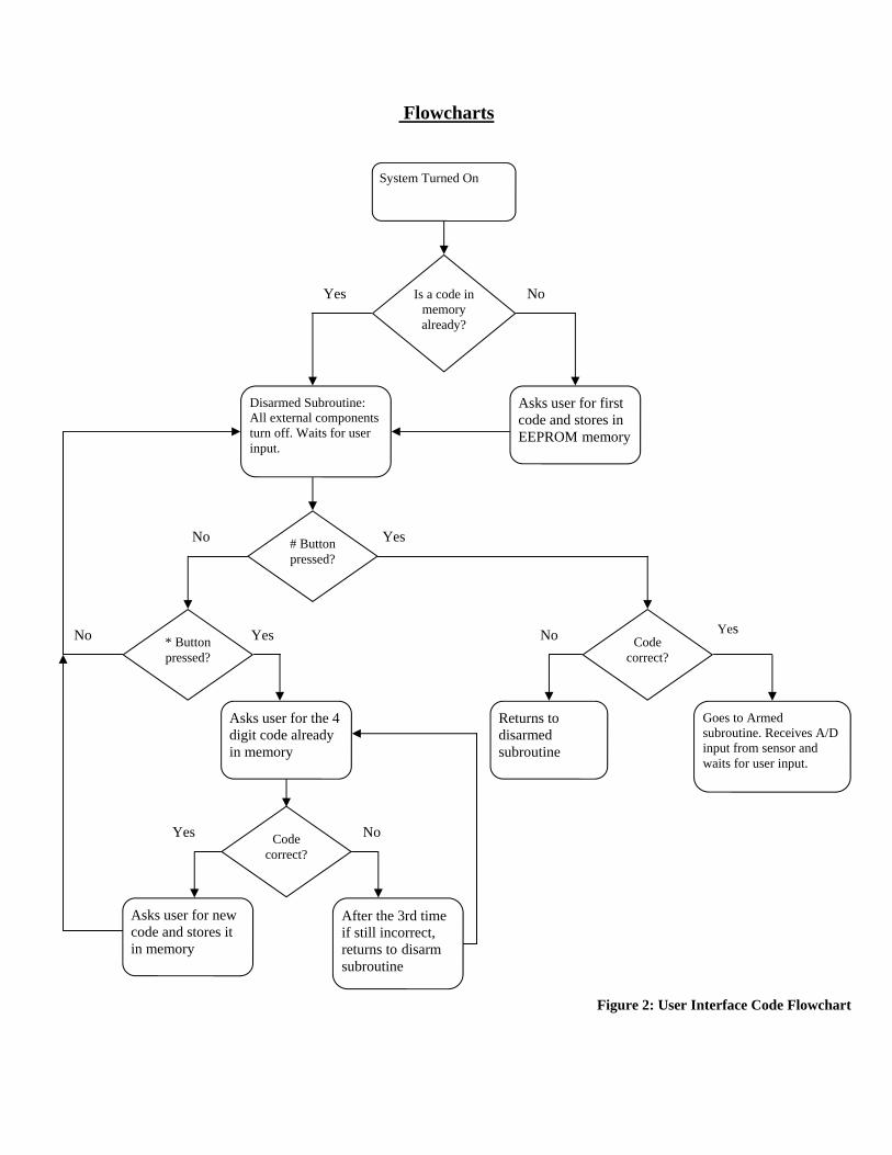
Flowcharts
Asks user for first code and stores in EEPROM memory
Yes
System Turned On
No
Disarmed Subroutine: All external components turn off. Waits for user input.
# Button pressed?
No
* Button pressed?
No Yes
Is a code in memory already?
Asks user for the 4 digit code already in memory
Code correct?
Yes
Asks user for new code and stores it in memory
Yes
After the 3rd time if still incorrect, returns to disarm subroutine
No
Code correct?
Returns to disarmed subroutine
No Yes
Goes to Armed subroutine. Receives A/D input from sensor and waits for user input.
Figure 2: User Interface Code Flowchart

Final Division of Labor Table 1: Division of Labor Item Angelique Dawkins Tyler Schlicter Ultrasound sensor integration with microprocessor, and A/D conversion code 100% 0Cell module coding, design with system, and PCB design 0 100%Camera coding, camera board PCB design 0 100%Voice chip coding and integration with amplifiers and speakers, message recording, and PCB design 100% 0User interface coding, coding for arm/disarm modes, and PCB layout for LCD and keypad 100% 0Fabrication of housing to enclose and present project 0 100%

Bill of Materials
Table 2: Bill of Materials
Item Cost/Unit Quantity Total LCD $19.99 1 $19.99 Keypad $13.66 1 $13.66 Microprocessor $7.50 2 $15.00 LM386 amplifier $1.09 1 $1.09 4 Ohm Speaker $7.85 2 $15.70 Cell Module $120.00 1 $120.00 Ultrasound Sensor $27.95 1 $27.95 Camera $25.00 1 $25.00 Miscellaneous $50.00 1 $50.00 Total $288.39

Gantt Chart
Project ICATS Angelique and Ty
7-Ja
n-09
21-Ja
n-09
4-Feb
-09
18-F
eb-0
9
4-M
ar-09
18-M
ar-09
1-Apr
-09
15-A
pr-0
9
Research (both)
Order/Acquire Parts (both)
Sensor Circuitry Build & Test(Angelique)
A/D Conversion (Angelique)
Camera Circuitry Build & Test(Ty)
Cell Module Circuitry Build &Test(Ty)
Voice Alarm - Build/Test (Angelique)
Whole System Testing (both)
PCB Board/ Final Tests (both)
Prepare for Final Presentation/ Demo
Main Task Extension
Figure 3: Gantt Chart

Appendices

Appendix A: PICBasic Code 'Keypad Arm/Disarming Code 'LCD Definitions DEFINE LCD_DREG PORTC 'define lcd data ports RC0:3 DEFINE LCD_DBIT 0 DEFINE LCD_RSREG PORTC 'define lcd register select port RC4 DEFINE LCD_RSBIT 4 DEFINE LCD_EREG PORTC 'define lcd enable port RC5 DEFINE LCD_EBIT 5 DEFINE LCD_BITS 4 'lcd bus size = 4 DEFINE LCD_LINES 4 'lcd lines = 4 DEFINE LCD_COMMANDUS 2000 'command delay time 'A/D Definitions TRISA.0 = 1 'setting AN0 as an analog input TRISA.1 = 0 'setting AN1 as an output (digital) ADCON1 = %00001110 'AN0 is the only analog port on PortA ADCON0 = %00000001 'enables the A/D converter ADCON2 = %00000111 'left justified, 0 TAD, and clock using A/D RC
'oscillator of frequency 1 Mhz result var byte 'result of A/D conversion OSCCON = %00000000 'setting for external crystal 'Voice Circuit Pin definitions TRISA.2 = 0 TRISA.3 = 0 TRISA.4 = 0 TRISA.5 = 1 M3 var porta.4 PD var porta.2 CE var porta.3 EOM VAR porta.5 P_R var porta.1 high ce low m3 'Other Variable Definitions ref var byte[4] 'value of code to be stored in memory new_ref var byte[4] 'value of code to be read from memory enter var byte [4] 'code to be entered to arm/disarm system check var byte 'variable to count when code stored in memory check = 0 'matches the one entered i var byte i = 0 lcd var byte[2] 'variable to keep values displayed on the same
'line lcd = $D4 countdown var byte 'to be used for arming countdown count_wrong var byte count_wrong = 0 TRISD.4 = 1
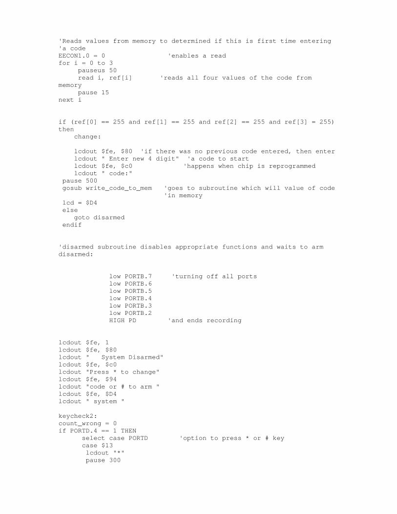
'Reads values from memory to determined if this is first time entering 'a code EECON1.0 = 0 'enables a read for i = 0 to 3 pauseus 50 read i, ref[i] 'reads all four values of the code from memory pause 15 next i if (ref[0] == 255 and ref[1] == 255 and ref[2] == 255 and ref[3] = 255) then change: lcdout $fe, $80 'if there was no previous code entered, then enter lcdout " Enter new 4 digit" 'a code to start lcdout $fe, $c0 'happens when chip is reprogrammed lcdout " code:" pause 500 gosub write_code_to_mem 'goes to subroutine which will value of code
'in memory lcd = $D4 else goto disarmed endif 'disarmed subroutine disables appropriate functions and waits to arm disarmed: low PORTB.7 'turning off all ports low PORTB.6 low PORTB.5 low PORTB.4 low PORTB.3 low PORTB.2 HIGH PD 'and ends recording lcdout $fe, 1 lcdout $fe, $80 lcdout " System Disarmed" lcdout $fe, $c0 lcdout "Press * to change" lcdout $fe, $94 lcdout "code or # to arm " lcdout $fe, $D4 lcdout " system " keycheck2: count_wrong = 0 if PORTD.4 == 1 THEN select case PORTD 'option to press * or # key case $13 lcdout "*" pause 300
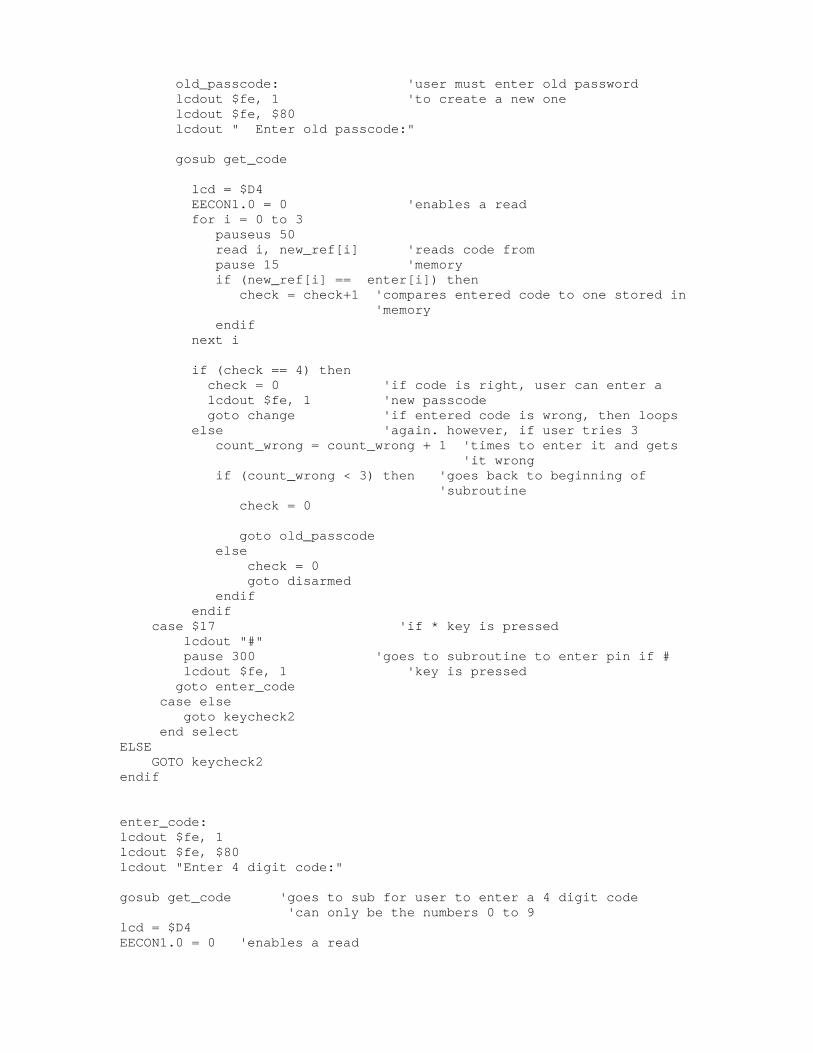
old_passcode: 'user must enter old password lcdout $fe, 1 'to create a new one lcdout $fe, $80 lcdout " Enter old passcode:" gosub get_code lcd = $D4 EECON1.0 = 0 'enables a read for i = 0 to 3 pauseus 50 read i, new_ref[i] 'reads code from pause 15 'memory if (new_ref[i] == enter[i]) then check = check+1 'compares entered code to one stored in
'memory endif next i if (check == 4) then check = 0 'if code is right, user can enter a lcdout $fe, 1 'new passcode goto change 'if entered code is wrong, then loops else 'again. however, if user tries 3 count_wrong = count_wrong + 1 'times to enter it and gets
'it wrong if (count_wrong < 3) then 'goes back to beginning of
'subroutine check = 0 goto old_passcode else check = 0 goto disarmed endif endif case $17 'if * key is pressed lcdout "#" pause 300 'goes to subroutine to enter pin if # lcdout $fe, 1 'key is pressed goto enter_code case else goto keycheck2 end select ELSE GOTO keycheck2 endif enter_code: lcdout $fe, 1 lcdout $fe, $80 lcdout "Enter 4 digit code:" gosub get_code 'goes to sub for user to enter a 4 digit code 'can only be the numbers 0 to 9 lcd = $D4 EECON1.0 = 0 'enables a read
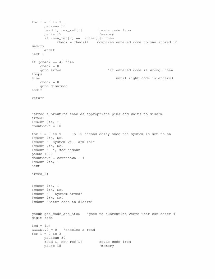
for i = 0 to 3 pauseus 50 read i, new_ref[i] 'reads code from pause 15 'memory if (new_ref[i] == enter[i]) then check = check+1 'compares entered code to one stored in memory endif next i if (check == 4) then check = 0 goto armed 'if entered code is wrong, then loops else 'until right code is entered check = 0 goto disarmed endif return 'armed subroutine enables appropriate pins and waits to disarm armed: lcdout $fe, 1 countdown = 10 for i = 0 to 9 'a 10 second delay once the system is set to on lcdout $fe, $80 lcdout " System will arm in:" lcdout $fe, $c0 lcdout " ", #countdown pause 1000 countdown = countdown - 1 lcdout $fe, 1 next armed_2: lcdout $fe, 1 lcdout $fe, $80 lcdout " System Armed" lcdout $fe, $c0 lcdout "Enter code to disarm" gosub get_code_and_AtoD 'goes to subroutine where user can enter 4 digit code lcd = $D4 EECON1.0 = 0 'enables a read for i = 0 to 3 pauseus 50 read i, new_ref[i] 'reads code from pause 15 'memory
if (new_ref[i] == enter[i]) then check = check+1 'compares entered code to one stored in memory endif next i if (check == 4) then check = 0 goto disarmed 'if entered code is wrong, then loops else 'until right code is entered check = 0 goto armed_2 endif return 'main A/D subroutine Main_A_D: ADCON0.1 = 1 'turns Go/Done bit high 'to start conversion process conversion: pause 5 if ADCON0.1 == 1 then 'while GO/DONE bit is high, keep converting goto conversion 'when bit goes low, stop and return endif result = 0 result = ADRESH ‘reads result from high address register to only get
'8 bits return 'below are all keypad subroutines to get and/or write data to PIC memory get_code: PAUSEUS 50 for i = 0 to 3 keycheck6: if PORTD.4 == 0 THEN keycheck6 if PORTD.4 == 1 THEN select case PORTD case $10 pauseUS 50 enter[i] = 1 lcdout $fe, lcd, "1" pause 200 case $18
pauseUS 50 enter[i] = 2 lcdout $fe, lcd, "2" pause 200 case $14 pauseUS 50 enter[i] = 3 lcdout $fe, lcd, "3" pause 200 case $12 pauseUS 50 enter[i] = 4 lcdout $fe, lcd, "4" pause 200 case $1a pauseUS 50 enter[i] = 5 lcdout $fe, lcd, "5" pause 200 case $16 pauseUS 50 enter[i] = 6 lcdout $fe, lcd, "6" Pause 200 case $11 pauseUS 50 enter[i] = 7 lcdout $fe, lcd, "7" pause 200 case $19 pauseUS 50 enter[i] = 8 lcdout $fe, lcd, "8" pause 200 case $15 pauseUS 50 enter[i] = 9 lcdout $fe, lcd, "9" pause 200 case $1b pauseUS 50
enter[i] = 0 lcdout $fe, lcd, "0" pause 200 case else goto keycheck6 end select ELSE GOTO keycheck6 endif lcd = lcd + 1 next i return get_code_and_AtoD: pauseUS 50 for i = 0 to 3 keycheck3: gosub Main_A_D if (result < 7) then high PORTB.7 'set extra pins high HIGH PORTB.6 HIGH PORTB.5 HIGH PORTB.4 HIGH PORTB.3 HIGH PORTB.2 low pd pause 25 high P_r pause 25 PULSOUT ce, 50 pause 50 high M3 play: if (Eom == 1) then

' lcdout $fe, $80 ' lcdout "Playing..." pause 200 gosub Main_A_D if (PORTD.4 == 0) then goto play else 'lcdout $fe, 1 GOTO KEYCHECK4 endif endif endif if PORTD.4 == 0 THEN keycheck3 keycheck4: if PORTD.4 == 1 THEN select case PORTD case $10 pauseUS 50 enter[i] = 1 lcdout $fe, lcd, "1" pause 200 case $18 pauseUS 50 enter[i] = 2 lcdout $fe, lcd, "2" pause 200 case $14 pauseUS 50 enter[i] = 3 lcdout $fe, lcd, "3" pause 200 case $12 pauseUS 50 enter[i] = 4 lcdout $fe, lcd, "4" pause 200 case $1a
pauseUS 50 enter[i] = 5 lcdout $fe, lcd, "5" pause 200 case $16 pauseUS 50 enter[i] = 6 lcdout $fe, lcd, "6" Pause 200 case $11 pauseUS 50 enter[i] = 7 lcdout $fe, lcd, "7" pause 200 case $19 pauseUS 50 enter[i] = 8 lcdout $fe, lcd, "8" pause 200 case $15 pauseUS 50 enter[i] = 9 lcdout $fe, lcd, "9" pause 200 case $1b pauseUS 50 enter[i] = 0 lcdout $fe, lcd, "0" pause 200 case else goto keycheck3 end select ELSE GOTO keycheck3 endif lcd = lcd + 1 next i return

write_code_to_mem: pauseUS 50 for i = 0 to 3 keycheck5: if PORTD.4 == 0 THEN keycheck5 if PORTD.4 == 1 THEN select case PORTD case $10 pauseUS 50 ref[i] = 1 write i, ref[i] pause 15 lcdout $fe, lcd, "1" pause 200 case $18 pauseUS 50 ref[i] = 2 write i, ref[i] pause 15 lcdout $fe, lcd, "2" pause 200 case $14 pauseUS 50 ref[i] = 3 write i, ref[i] pause 15 lcdout $fe, lcd, "3" pause 200 case $12 pauseUS 50 ref[i] = 4 write i, ref[i] pause 15 lcdout $fe, lcd, "4" pause 200 case $1a pauseUS 50 ref[i] = 5 write i, ref[i] pause 15 lcdout $fe, lcd, "5" pause 200 case $16 pauseUS 50

ref[i] = 6 write i, ref[i] pause 15 lcdout $fe, lcd, "6" Pause 200 case $11 pauseUS 50 ref[i] = 7 write i, ref[i] pause 15 lcdout $fe, lcd, "7" pause 200 case $19 pauseUS 50 ref[i] = 8 write i, ref[i] pause 15 lcdout $fe, lcd, "8" pause 200 case $15 pauseUS 50 ref[i] = 9 write i, ref[i] pause 15 lcdout $fe, lcd, "9" pause 200 case $1b pauseUS 50 ref[i] = 0 write i, ref[i] pause 15 lcdout $fe, lcd, "0" pause 200 case else goto keycheck5 end select ELSE GOTO keycheck5 endif lcd = lcd + 1 next i return

Appendix B: Camera Code
' -----[ I/O Definitions ]--------------------------------------------- shutter VAR PortC.4 power VAR PortC.6 tripped VAR PortD.1 sys_arm VAR PortD.2 ' -----[ Constants ]--------------------------------------------------- i VAR BYTE ' -----[ Program Code ]------------------------------------------------ Main: i = 1 Low tripped Low shutter Low power low sys_arm TRISC.4 = 0 'set PortC.4 to an output TRISC.6 = 0 'set PortC.6 to an output TRISD.1 = 1 'set PortD.1 to an input TRISD.2 = 1 'set PortD.2 to an input GoSub LCD_Initialize LCDOut "Welcome To The" Pause 1000 LCDOUT $FE, $C0 'Cursor to beginning of 2nd line LCDOUT "Camera Program" armed: IF sys_arm then goto check_sensor else goto armed endif check_sensor: IF tripped Then pulsout power, 500 GoSub LCD_Initialize LCDOut "Alarm Actived" Pause 2000 Loop: For i = 1 TO 5 Pulsout shutter, 500 GoSub LCD_Initialize LCDOut "Picture Taken" Pause 500 Gosub LCD_Initialize LCDOUt "Between snapshots" Pause 8000 Next i
Else GoTo check_sensor EndIF End ' -----[ Subroutines ]----------------------------------------------------- LCD_Initialize: LCDOut $fe, 1 'clear screen Pause 500 LCDOut $fe, $80 ' cursor to beginning of first line Return ' ----------------------------------------------------