Send document comments to nexus7k-docfeedback@cisco · PIM 4-1 BGP autonomous systems MBGP 1-11...
170
Send document comments to [email protected] IN-1 Cisco Nexus 7000 Series NX-OS Multicast Routing Configuration Guide OL-23238-01 INDEX Symbols (*, G) description 1-4 state creation 4-4 static groups 2-6 static groups on the OIF 2-6 (S, G) description 1-3 IGMPv3 snooping 5-3 state creation 4-4 static groups 2-6 static groups on the OIF 2-6 A Anycast-RP configuring an Anycast-RP set 4-37 description 4-15 MSDP (Note) 6-2 Any Source Multicast. See ASM mode ASM mode configuring 4-29 configuring shared trees only 4-40 description 4-2 join-prune messages 4-3 shared trees only, description 4-17 autonomous systems MBGP 1-11 MSDP 6-2 Auto-RP candidate RP configuration steps 4-36 candidate RPs, configuring 4-35 configuring 4-35 description 4-5 mapping agent configuration steps 4-36 mapping agent election process 4-8 mapping agents configuring 4-35 configuring route maps 4-45 RP-Announce messages 4-5 RP-Discovery messages 4-5 Auto-RPs troubleshooting 4-8 B BFD PIM 4-1 BGP autonomous systems MBGP 1-11 MSDP 6-2 MSDP 6-2 bidirectional mode. See Bidir mode Bidir mode configuring 4-29 description 1-9, 4-2 DFs, description 4-17 join-prune messages 4-3 multicast forwarding (Note) 1-5 bootstrap router. See BSRs BSR-candidate priorities different 4-7 same 4-7 BSR RP-candidate election
Transcript of Send document comments to nexus7k-docfeedback@cisco · PIM 4-1 BGP autonomous systems MBGP 1-11...

Send document comments to nexus7k -doc feedback@c i sco .com
Cisco Nexus 7000 SOL-23238-01
I N D E X
Symbols
(*, G)
description 1-4
state creation 4-4
static groups 2-6
static groups on the OIF 2-6
(S, G)
description 1-3
IGMPv3 snooping 5-3
state creation 4-4
static groups 2-6
static groups on the OIF 2-6
A
Anycast-RP
configuring an Anycast-RP set 4-37
description 4-15
MSDP (Note) 6-2
Any Source Multicast. See ASM mode
ASM mode
configuring 4-29
configuring shared trees only 4-40
description 4-2
join-prune messages 4-3
shared trees only, description 4-17
autonomous systems
MBGP 1-11
MSDP 6-2
Auto-RP
candidate RP configuration steps 4-36
candidate RPs, configuring 4-35
configuring 4-35
description 4-5
mapping agent configuration steps 4-36
mapping agent election process 4-8
mapping agents
configuring 4-35
configuring route maps 4-45
RP-Announce messages 4-5
RP-Discovery messages 4-5
Auto-RPs
troubleshooting 4-8
B
BFD
PIM 4-1
BGP
autonomous systems
MBGP 1-11
MSDP 6-2
MSDP 6-2
bidirectional mode. See Bidir mode
Bidir mode
configuring 4-29
description 1-9, 4-2
DFs, description 4-17
join-prune messages 4-3
multicast forwarding (Note) 1-5
bootstrap router. See BSRs
BSR-candidate priorities
different 4-7
same 4-7
BSR RP-candidate election
IN-1eries NX-OS Multicast Routing Configuration Guide

Send document comments to nexus7k -doc feedback@c i sco .com
Index
identical group-list 4-13
identical group-list and identical RP priorities 4-14
identical group-list with different RP priorities 4-10
identical group-list with identical RP priorities 4-11
most specific group-list 4-9, 4-12
BSRs
candidate BSR configuration steps 4-32
candidate BSRs
configuring 4-31
description 4-4
candidate RP configuration steps 4-32
candidate RP election process 4-7
candidate-RP messages
description 4-5
candidate RPs, configuring 4-32
configuring 4-31
description 4-4
messages
description 4-4
enabling listen and forward 4-5
route maps, configuring 4-45
RP configuration steps 4-32
troubleshooting 4-7
D
designated forwarders. See DFs
designated routers. See DRs
DFs
Bidir mode (Note) 1-5
description 4-17
documentation
additional publications i-xiii
related documents i-xii
DRs
description 4-16
PIM domains 1-7
priority and PIM hello message 4-3
SSM mode 4-42
IN-2Cisco Nexus 7000 Series NX-OS Multicast Routing Configuration G
F
F Series modules 1-13, 7-1
H
high availability, multicast 1-13
I
IGMP
all-hosts multicast group 2-2
configuration, example 2-15
description 2-1
enabling 2-1
IGMPv3
changes from IGMPv2 2-2
description 2-3
SSM 2-3
licensing requirements 2-4
parameters
configuring 2-5
default settings 2-5
PIM domains 1-7
prerequisites 2-4
queriers
description 2-3
designated 2-2
TTL 2-3
restarting the process 2-13
version, default (IGMPv2) 2-2
versions, description 2-2
virtualization, VDCs and VRFs 2-4
IGMP commands
iip igmp enforce-router-alert 2-13
ip igmp access-group 2-10
ip igmp flush-routes 2-13, 2-14
ip igmp group-timeout 2-10
ip igmp immediate-leave 2-11
uideOL-23238-01

Send document comments to nexus7k -doc feedback@c i sco .com
Index
ip igmp join-group 2-9
ip igmp last-member-query-count 2-10
ip igmp last-member-query-response-time 2-10
ip igmp querier-timeout 2-9
ip igmp query-interval 2-10
ip igmp query-max-response-time 2-10
ip igmp query-timeout 2-10
ip igmp report-link-local-groups 2-10
ip igmp report-policy 2-10
ip igmp robustness-variable 2-9
ip igmp ssm-translate 2-12
ip igmp startup-query-count 2-9
ip igmp startup-query-interval 2-9
ip igmp static-oif 2-9
ip igmp version 2-8
IGMP configuration
access groups 2-7
example 2-15
group membership timeout 2-2, 2-7
immediate leave 2-7
last member query count 2-7
last member query response interval 2-7
member query response interval 2-4
number of query messages 2-3
parameters 2-5
parameters, default settings 2-5
querier timeout 2-6
query interval 2-7
query maximum response time 2-3
query max response time 2-6
report link local multicast groups 2-7
report policy 2-7
reports for link local addresses 2-4
robustness value 2-4, 2-6
startup query count 2-6
startup query interval 2-6
static multicast groups 2-6
Static multicast groups on OIF 2-6
version 2-6
Cisco NexuOL-23238-01
IGMP membership reports
IGMPv3 suppression 2-3
initiating receipt of multicast data 2-2
SSM translation 2-11
suppressing 2-3
IGMP queriers
description 2-3
designated 2-2
TTL 2-3
IGMP show commands
show ip igmp groups 2-14
show ip igmp interface 2-14
show ip igmp local-groups 2-14
show ip igmp route 2-14
show running-configuration igmp 2-14
show startup-configuration igmp 2-14
IGMP snooping
configuration, example 5-17
description 5-1
licensing requirements 5-4
lookup mode 5-4
membership report suppression 5-3
parameters, configuring 5-7, 5-9
parameters, default settings 5-6
prerequisites 5-5
proprietary features 5-2
querier, description 5-3
statistics 5-17
switch example 5-2
troubleshooting 5-10
virtualization, VDCs and VRFs 5-4
vPC statistics 5-17
IGMP snooping commands
ip igmp snooping 5-8, 5-11, 5-12
ip igmp snooping explicit-tracking 5-8, 5-12
ip igmp snooping fast-leave 5-8, 5-12
ip igmp snooping last-member-query-interval 5-8, 5-12
IN-3s 7000 Series NX-OS Multicast Routing Configuration Guide

Send document comments to nexus7k -doc feedback@c i sco .com
Index
ip igmp snooping link-local-groups-suppression 5-8, 5-13
ip igmp snooping mrouter interface 5-13
ip igmp snooping querier 5-8, 5-12, 5-13
ip igmp snooping report-suppression 5-8, 5-13
ip igmp snooping static-group 5-13
ip igmp snooping v3-report-suppression 5-9, 5-13, 5-14
IGMP snooping configuration
enabling 5-7, 5-9
example 5-17
explicit tracking 5-9
fast leave 5-9
IGMPv3 report suppression 5-7, 5-10
last member query interval 5-9
Link-local groups suppression 5-7, 5-10
multicast routers 5-10
parameters
configuring 5-7, 5-9
default settings 5-6
report suppression 5-7, 5-10
snooping querier 5-10
static groups 5-10
IGMP snooping show commands
show ip igmp snooping 5-16
show ip igmp snooping explicit-tracking 5-16
show ip igmp snooping groups 5-16
show ip igmp snooping mroute 5-16
show ip igmp snooping querier 5-16
IGMPv3
changes from IGMPv2 2-2
description 2-3
SSM 2-3
interdomain multicast protocols
MBGP 1-11
MSDP 1-10
SSM 1-10
Internet Group Management Protocol. See IGMP
IN-4Cisco Nexus 7000 Series NX-OS Multicast Routing Configuration G
L
Layer 3 7-3
licensing requirements, multicast 1-13
M
mapping agents. See Auto-RP
MBGP
interdomain multicast protocol 1-11
PIM domains 1-8
MFIB and M6FIB
description 1-11
flushing routes 4-52
OIF-list and RPF interface (Note) 4-17
MLD
configuration, example 3-13
description 3-1
enabling 3-1
licensing requirements 3-4
listener reports 3-2
MLDv2
changes from MLDv1 3-2
SSM 3-3
parameters
default settings 3-5
PIM6 domains 1-8
prerequisites 3-5
queriers
description 3-3
designated 3-3
TTL 3-3
SSM translation 3-11
versions, description 3-2
virtualization, VDCs and VRFs 3-4
MLD commands
ipv6 mld access-group 3-11
ipv6 mld group-timeout 3-10
ipv6 mld immediate-leave 3-11
uideOL-23238-01

Send document comments to nexus7k -doc feedback@c i sco .com
Index
ipv6 mld join-group 3-9
ipv6 mld last-member-query-count 3-10
ipv6 mld last-member-query-response-time 3-10
ipv6 mld querier-timeout 3-10
ipv6 mld query-interval 3-10
ipv6 mld query-max-response-time 3-10
ipv6 mld query-timeout 3-10
ipv6 mld report-link-local-groups 3-10
ipv6 mld report-policy 3-10
ipv6 mld robustness-variable 3-10
ipv6 mld ssm-translate 3-12
ipv6 mld startup-query-count 3-9
ipv6 mld startup-query-interval 3-9
ipv6 mld static-oif 3-9
ipv6 mld version 3-9
MLD configuration
access groups 3-8
example 3-13
frequency and number of query messages 3-3
group membership timeout 3-3, 3-7
immediate leave 3-8
last member query count 3-7
last member query response interval 3-4, 3-7
parameters, default settings 3-5
querier timeout 3-7
query interval 3-7
query maximum response time 3-3
query max response time 3-7
report link local multicast groups 3-7
report policy 3-7
reports for link local addresses 3-4
robustness value 3-4, 3-7
startup query count 3-7
startup query interval 3-6
static multicast groups 3-6
static multicast groups on OIF 3-6
version 3-6
MLD queriers
description 3-3
Cisco NexuOL-23238-01
designated 3-3
TTL 3-3
MLD show commands
show ipv6 mld groups 3-13
show ipv6 mld interface 3-11, 3-13
show ipv6 mld local-groups 3-13
show ipv6 mld route 3-13
MLDv2
changes from MLDv1 3-2
SSM 3-3
MRIB and M6RIB
description 1-11
flushing routes 4-52
OIF-list and RPF interface (Note) 4-17
MSDP
Anycast-RP (Note) 6-2
configuration, example 6-15
description 6-1
full mesh, description 6-2
interdomain multicast protocol 1-10
licensing requirements 6-3
mesh groups, description 6-3
parameters, default settings 6-4
peering, steps to configure 6-4
peer-RPF flooding, description 6-3
peers, description 6-1
PIM domains 1-7, 6-1
prerequisites 6-4
SA cache, description 6-3
SA messages, and PIM register messages 6-3
SA messages, description 6-1, 6-2
statistics
clearing 6-14
displaying 6-14
virtualization, VDCs and VRFs 6-3
MSDP commands
feature msdp 6-6
ip msdp description 6-9
ip msdp flush-routes 6-13
IN-5s 7000 Series NX-OS Multicast Routing Configuration Guide

Send document comments to nexus7k -doc feedback@c i sco .com
Index
ip msdp group-limit 6-11
ip msdp mesh-group 6-12
ip msdp originator-id 6-11
ip msdp password 6-9
ip msdp peer 6-7
ip msdp sa-interval 6-11
ip msdp sa-limit 6-9
ip msdp sa-policy 6-9
ip msdp shutdown 6-9
MSDP configuration
administrative shutdown 6-8
commands, cached (Note) 6-5
description field 6-8
enabling 6-5
example 6-15
group limit 6-10
MD5 password 6-8
mesh groups 6-11
originator interface name 6-10
parameters, default settings
6-4
peering, steps to configure 6-4
peers and peering relationship 6-6
restarting the MSDP process 6-12
SA messages
interval 6-10
limit 6-8
policy IN 6-8
policy OUT 6-8
MSDP show commands
show ip msdp 6-14
show ip msdp count 6-13
show ip msdp mesh-group 6-13
show ip msdp peer 6-13
show ip msdp policy statistics sa-policy 6-14
show ip msdp route 6-14
show ip msdp rpf 6-13
show ip msdp sa-cache 6-14
show ip msdp sources 6-13
IN-6Cisco Nexus 7000 Series NX-OS Multicast Routing Configuration G
show ip msdp summary 6-13
MSDP statistics commands
clear ip msdp peer 6-14
clear ip msdp policy statistics sa-policy 6-14
clear ip msdp route 6-14
clear ip msdp sa-cache 6-14
clear ip msdp statistics 6-14
MTU limitation 1-13
multicast
administratively scoped IP, description 4-17
channel 1-1
description 1-1
distribution modes
ASM 4-2
Bidir 4-2
SSM 4-2
forwarding 1-5
group 1-1
high availability 1-13
interdomain protocols
MBGP 1-11
MSDP 1-10
SSM 1-10
IPv4 addresses 1-1
IPv6 addresses 1-1
licensing requirements 1-13
protocols
IGMP 2-1
IGMP snooping 5-1
MBGP 1-8
MLD 3-1
MSDP 6-1
PIM and PIM6 1-6
restarting processes
IGMP 2-13
MSDP 6-12
PIM and PIM6 4-52
static MAC address 5-4
troubleshooting 1-1
uideOL-23238-01

Send document comments to nexus7k -doc feedback@c i sco .com
Index
tunnel interfaces 1-1
multicast distribution trees
bidirectional 1-4
description 1-2
PIM 1-6
shared 1-3, 4-1
source 1-3, 4-1
SPTs, description 1-3
Multicast Forwarding Information Base. See MFIB and M6FIB
Multicast Listener Discovery. See MLD
Multicast Routing Information Base. See MRIB and M6RIB
Multicast Source Discovery Protocol. See MSDP
Multiprotocol BGP. See MBGP
O
OIF
DFs 4-17
RPF check 1-5
outgoing interface. See OIF
P
PIM
BFD 4-1, 4-17
configuring BFD 4-54
failure detection 4-3, 4-17
multiple RPs 4-6
troubleshooting 1-1
tunnel interfaces 4-2
PIM6 commands
feature pim6 4-22
iipv6 pim bidir-rp-limit 4-27
ipv6 pim anycast-rp 4-39
ipv6 pim border 4-28
ipv6 pim bsr bsr-policy 4-52
ipv6 pim bsr-candidate 4-34
Cisco NexuOL-23238-01
ipv6 pim bsr listen 4-27
ipv6 pim bsr rp-candidate-policy 4-52
ipv6 pim dr-priority 4-28
ipv6 pim flush-routes 4-54
ipv6 pim hello-interval 4-28
ipv6 pim jp-policy 4-52
ipv6 pim log-neighbor-changes 4-51
ipv6 pim neighbor-policy 4-28
ipv6 pim register-policy 4-51
ipv6 pim register-rate-limit 4-27
ipv6 pim rp-address 4-31
ipv6 pim rp-candidate 4-34
ipv6 pim sparse-mode 4-28
ipv6 pim ssm range 4-43
ipv6 pim use-shared-tree-only 4-41
PIM and PIM6 4-15
configuration steps 4-20
configuring, description 4-20
dense mode 1-6
description 1-6, 4-1
enabling 4-2
guidelines and limitations 4-18
licensing requirements 4-18, 7-3
message filtering 4-48
parameters, default settings 4-19
prerequisites 4-18
refreshing state 4-3
sparse mode 1-6, 4-1
statistics
clearing 4-57
displaying 4-57
virtualization, VDCs and VRFs 4-18
PIM and PIM6 configuration
Auto-RP candidate RP policy (PIM only) 4-48
Auto-RP mapping agent policy (PIM only) 4-48
Auto-RP message action (PIM only) 4-22
Bidir RP limit 4-23
BSR candidate RP policy 4-48
BSR message action 4-22
IN-7s 7000 Series NX-OS Multicast Routing Configuration Guide

Send document comments to nexus7k -doc feedback@c i sco .com
Index
BSR policy 4-48
description 4-20
designated router priority 4-23
domain border 4-24
examples
ASM mode using BSR 4-58
ASM mode using PIM Anycast-RP 4-60
Bidir mode using Auto-RP 4-59
SSM mode 4-58
feature, enabling 4-21
flushing routes 4-52
hello authentication mode 4-23
hello interval 4-23
Initial holddown period 4-23
join-prune policy 4-48
logging neighbor changes 4-48
neighbor policy 4-24
parameters, default settings 4-19
PIM register policy 4-48
Register rate limit 4-23
restarting the processes 4-52
sparse mode, enabling 4-23
sparse mode parameters 4-22
steps to configure 4-20
PIM and PIM6 domains
border parameter 4-17
description
PIM 1-7
PIM6 1-8
MSDP (PIM) 6-1
PIM and PIM6 show commands
show {ip | ipv6} mroute 4-56
show {ip | ipv6} pim df 4-56
show {ip | ipv6} pim group-range 4-56
show {ip | ipv6} pim interface 4-56
show {ip | ipv6} pim neighbor 4-56
show {ip | ipv6} pim oif-list 4-56
show {ip | ipv6} pim policy statistics 4-57
show {ip | ipv6} pim route 4-56
IN-8Cisco Nexus 7000 Series NX-OS Multicast Routing Configuration G
show {ip | ipv6} pim rp 4-56
show {ip | ipv6} pim rp-hash 4-56
show {ip | ipv6} pim statistics 4-57
show {ip | ipv6} pim vrf 4-56
show running-configuration {pim | pim6} 4-56
show startup-configuration {pim | pim6} 4-56
PIM and PIM6 statistics commands
clear {ip | ipv6} pim interface statistics 4-57
clear {ip | ipv6} pim policy statistics 4-57
clear {ip | ipv6} pim statistics 4-57
PIM commands
feature pim 4-22
ip mroute 4-45
ip pim anycast-rp 4-39
ip pim auto-rp listen 4-25
ip pim auto-rp mapping-agent 4-37
ip pim auto-rp mapping-agent-policy 4-51
ip pim auto-rp rp-candidate 4-37
ip pim auto-rp rp-candidate-policy 4-50
ip pim bidir-rp-limit 4-26
ip pim border 4-27
ip pim bsr bsr-policy 4-50
ip pim bsr-candidate 4-33
ip pim bsr listen 4-25
ip pim bsr rp-candidate-policy 4-50
ip pim dr-priority 4-26
ip pim flush-routes 4-53
ip pim hello-authentication ah-md5 4-26
ip pim hello-interval 4-26
ip pim jp-policy 4-51
ip pim log-neighbor-changes 4-50
ip pim neighbor-policy 4-27
ip pim register-policy 4-50
ip pim register-rate-limit 4-26
ip pim rp-address 4-30
ip pim rp-candidate 4-34
ip pim send-rp-announce 4-37
ip pim send-rp-discovery 4-37
ip pim sparse-mode 4-26
uideOL-23238-01

Send document comments to nexus7k -doc feedback@c i sco .com
Index
ip pim ssm range 4-43
ip pim use-shared-tree-only 4-41
ip routing multicast holddown 4-26
PIM messages
Anycast-RP 4-15
authenticating hello with MD5 hash value 4-3
DR priority 4-3
filtering join-prune 4-3
hello, description 4-3
join and state creation 4-4
join-prune, description 4-3
join-prune and join or prune (Note) 4-3
MSDP SA messages 6-3
register
description 4-16
filtering 4-16
MSDP 6-1
prefix list 4-29
Protocol Independent Multicast. See PIM or PIM6 1-6
proxy routing 7-3
R
related documents i-xiii
rendezvous points. See RPs
restarting multicast processes
IGMP 2-13
MSDP 6-12
PIM and PIM6 4-52
reverse path forwarding. See RPF
route map 4-29
route maps
Auto-RP mapping agent configuration 4-45
BSR configuration 4-45
RP configuraion 4-45
RP address 4-29
RP-Announce messages, and Auto-RP 4-5
RP-Discovery messages, and Auto-RP 4-5
RPF
Cisco NexuOL-23238-01
check 1-5
configuring routes 4-44
DFs 4-17
PIM 1-6
static multicast 1-9
RPs
address selection 4-5
Anycast-RP, description 4-15
Auto-RP, description 4-5
BSRs, description 4-4
default mode (ASM) 1-9
description 4-4
MSDP 6-1
multiple in a PIM domain 4-6
PIM domains 1-7
route maps, configuring 4-45
selection process 4-5
static, description 4-4
static addresses, configuring 4-29
RP trees. See multicast distribution trees, shared
RPTs. See multicast distribution trees, shared
S
shortest path trees. See SPTs
Source-Specific Multicast. See SSM mode
SPTs
description 1-3
SSM mode 4-3
switchover to source tree 4-17
SSM mapping. See SSM translation
SSM mode
configuring 4-42
description 1-9, 4-2
DRs 4-42
group range, configuring 4-42
IGMPv3 2-3
interdomain multicast protocol 1-10
join-prune messages 4-3
IN-9s 7000 Series NX-OS Multicast Routing Configuration Guide

Send document comments to nexus7k -doc feedback@c i sco .com
Index
PIM6 domains 1-8
SSM translation
description 2-11
IGMPv1 and IGMPv2 2-3
MLD 3-11
MLDv1 3-3
T
troubleshooting 1-1, 4-9, 4-40, 5-1, 5-10
Auto-RP 4-8
BSRs 4-7
tunnel interfaces 1-1
V
virtual port channels. See vPCs.
VLAN interface 7-3
vPCs 4-40
and multicast 1-12
Bidir mode not supported with 4-29
displaying statistics 5-17
IGMP snooping configuration guidelines 5-5
IN-10Cisco Nexus 7000 Series NX-OS Multicast Routing Configuration G
uideOL-23238-01

Send document comments to nexus7k -doc feedback@c i sco .com
New and Changed Information
This chapter provides release-specific information for each new and changed feature in the Cisco Nexus 7000 Series NX-OS Multicast Routing Configuration Guide. The latest version of this document is available at the following Cisco website:http://www.cisco.com/en/US/docs/switches/datacenter/sw/5_x/nx-os/multicast/command/reference/n7k_mcr_cmd_5x.html
To check for additional information about this Cisco NX-OS Release, see the Cisco NX-OS Release Notes available at the following Cisco website:http://www.cisco.com/en/US/products/ps9402/prod_release_notes_list.htmll
Table 1 summarizes the new and changed features for the Cisco Nexus 7000 Series NX-OS Multicast Routing Configuration Guide, and tells you where they are documented.
Table 1 New and Changed Features for Release 5.x
Feature Description
Changed in Release Where Documented
Configuring lookup mode to MAC and assigning a static MAC address
You can configure IGMP snooping to use the forwarding lookup mode as MAC-based, as well as assign a static MAC address.
5.2(1) Chapter 1, “Configuring IGMP Snooping”
Configuring PIMv4 on GRE tunnel interfaces
You can configure multicast on GRE tunnel interfaces including outgoing interfaces (OIFs).
5.2(1) Chapter 1, “Configuring PIM and PIM6”
Configuring multicast interoperation with F Series modules
You can configure multicast interoperation with F series and M series modules.
5.1(1) Chapter 1, “Configuring Multicast Interoperation with N7K-F132-15 Modules”
Multicast routing initial holddown period
You can specify the initial holddown period for both IPv4 and IPv6 networks.
4.2(1) Chapter 1, “Configuring PIM or PIM6 Sparse Mode”
9Cisco Nexus 7000 Series NX-OS Multicast Routing Configuration Guide
OL-23238-01

Send document comments to nexus7k -doc feedback@c i sco .com
New and Changed Information
Use a route-map policy for commands
You can specify group prefixes in a route-map policy rather than specifying them on the command line for these commands:
• ip igmp join-group
• ip igmp static-oif
• ip pim rp-address
• ip pim ssm range
• ipv6 [icmp] mld join-group
• ipv6 [icmp] mld static-oif
• ipv6 pim rp-address
• ipv6 pim ssm range
4.2(1) Chapter 1, “Configuring IGMP”
Chapter 1, “Configuring MLD”
Chapter 1, “Configuring Static RPs”
Chapter 1, “Configuring SSM”
Virtual Port Channel (vPC)
Cisco NX-OS software for the Nexus 7000 Series devices does not support PIM SSM or BIDR on vPC. Cisco NX-OS software fully supports PIM ASM on vPC.
4.1(4) Chapter 1, “Virtual Port Channels and Multicast”
Virtual Port Channel (vPC)
A virtual port channel (vPC) allows a single device to use a port channel across two upstream switches.
4.1(3) Chapter 1, “Virtual Port Channels and Multicast”
Chapter 1, “Verifying the IGMP Configuration”
Chapter 1, “Configuring ASM and Bidir”
Chapter 1, “Guidelines and Limitations for IGMP Snooping”
Chapter 1, “Displaying IGMP Snooping Statistics”
Immediate leave Option that minimizes the leave latency of IGMPv2 or MLDv1 group memberships on a given IGMP or MLD interface because the device does not send group-specific queries.
4.1(3) Chapter 1, “Configuring IGMP Interface Parameters”
Chapter 1, “Configuring MLD Interface Parameters”
Table 1 New and Changed Features for Release 5.x (continued)
Feature Description
Changed in Release Where Documented
10Cisco Nexus 7000 Series NX-OS Multicast Routing Configuration Guide
OL-23238-01

Send document comments to nexus7k -doc feedback@c i sco .com
Preface
This preface describes the audience, organization, and conventions of the Cisco Nexus 7000 Series NX-OS Multicast Routing Configuration Guide. It also provides information on how to obtain related documentation.
This chapter includes the following sections:
• Audience, page 11
• Organization, page 11
• Document Conventions, page 12
• Related Documentation, page 13
• Obtaining Documentation and Submitting a Service Request, page 14
AudienceThis publication is for experienced users who configure and maintain Cisco NX-OS devices.
OrganizationThis reference is organized as follows:
Chapter and Title Description
Chapter 1, “Overview” Describes the Cisco NX-OS multicast features.
Chapter 1, “Configuring IGMP” Describes how to configure the Cisco NX-OS IGMP features.
Chapter 1, “Configuring MLD” Describes how to configure the Cisco NX-OS MLD features.
Chapter 1, “Configuring PIM and PIM6” Describes how to configure the Cisco NX-OS PIM and PIM6 features.
Chapter 1, “Configuring IGMP Snooping” Describes how to configure the Cisco NX-OS IGMP snooping feature.
Chapter 1, “Configuring MSDP” Describes how to configure the Cisco NX-OS MSDP feature.
11Cisco Nexus 7000 Series NX-OS Multicast Routing Configuration Guide
OL-23238-01

Send document comments to nexus7k -doc feedback@c i sco .com
Preface
Document ConventionsCommand descriptions use these conventions:
Screen examples use these conventions:
This document uses the following conventions:
Note Means reader take note. Notes contain helpful suggestions or references to material not covered in the manual.
Caution Means reader be careful. In this situation, you might do something that could result in equipment damage or loss of data.
Tip Means the following information will help you solve a problem.
Chapter 1, “Configuring Multicast Interoperation with N7K-F132-15 Modules.”
Describes how to configure multicast interoperation with F series and M series modules.
Appendix 1, “IETF RFCs for IP Multicast” Contains the RFCs related to the Cisco NX-OS multicast features.
Chapter and Title Description
Convention Description
boldface font Commands and keywords are in boldface.
italic font Arguments for which you supply values are in italics.
[ ] Elements in square brackets are optional.
[ x | y | z ] Optional alternative keywords are grouped in brackets and separated by vertical bars.
string A nonquoted set of characters. Do not use quotation marks around the string or the string will include the quotation marks.
screen font Terminal sessions and information that the switch displays are in screen font.
boldface screen font
Information you must enter is in boldface screen font.
italic screen font Arguments for which you supply values are in italic screen font.
< > Nonprinting characters, such as passwords, are in angle brackets.
[ ] Default responses to system prompts are in square brackets.
!, # An exclamation point (!) or a pound sign (#) at the beginning of a line of code indicates a comment line.
12Cisco Nexus 7000 Series NX-OS Multicast Routing Configuration Guide
OL-23238-01

Send document comments to nexus7k -doc feedback@c i sco .com
Preface
Related DocumentationCisco NX-OS includes the following documents:
Release Notes
Cisco Nexus 7000 Series NX-OS Release Notes, Release 5.x
NX-OS Configuration Guides
Cisco Nexus 7000 Series NX-OS Configuration Examples, Release 5.x
Configuring the Cisco Nexus 2000 Series Fabric Extender
Cisco Nexus 7000 Series NX-OS FabricPath Configuration Guide
Configuring Feature Set for FabricPath
Cisco NX-OS FCoE Configuration Guide for Cisco Nexus 7000 and Cisco MDS 9500
Cisco Nexus 7000 Series NX-OS Fundamentals Configuration Guide, Release 5.x
Cisco Nexus 7000 Series NX-OS High Availability and Redundancy Guide, Release 5.x
Cisco Nexus 7000 Series NX-OS Interfaces Configuration Guide, Release 5.x
Cisco Nexus 7000 Series NX-OS Layer 2 Switching Configuration Guide, Release 5.x
Cisco Nexus 7000 Series NX-OS LISP Configuration Guide
Cisco Nexus 7000 Series NX-OS MPLS Configuration Guide
Cisco Nexus 7000 Series NX-OS Multicast Routing Configuration Guide, Release 5.x
Cisco Nexus 7000 Series NX-OS OTV Configuration Guide
Cisco Nexus 7000 Series OTV Quick Start Guide
Cisco Nexus 7000 Series NX-OS Quality of Service Configuration Guide, Release 5.x
Cisco Nexus 7000 Series NX-OS SAN Switching Configuration Guide
Cisco Nexus 7000 Series NX-OS Security Configuration Guide, Release 5.x
Cisco Nexus 7000 Series NX-OS System Management Configuration Guide, Release 5.x
Cisco Nexus 7000 Series NX-OS Unicast Routing Configuration Guide, Release 5.x
Cisco Nexus 7000 Series NX-OS Virtual Device Context Configuration Guide, Release 5.x
Cisco Nexus 7000 Series NX-OS Virtual Device Context Quick Start, Release 5.x
NX-OS Command References
Cisco Nexus 7000 Series NX-OS Command Reference Master Index
Cisco Nexus 7000 Series NX-OS FabricPath Command Reference
Cisco NX-OS FCoE Command Reference for Cisco Nexus 7000 and Cisco MDS 9500
Cisco Nexus 7000 Series NX-OS Fundamentals Command Reference
Cisco Nexus 7000 Series NX-OS High Availability Command Reference
Cisco Nexus 7000 Series NX-OS Interfaces Command Reference
Cisco Nexus 7000 Series NX-OS Layer 2 Switching Command Reference
13Cisco Nexus 7000 Series NX-OS Multicast Routing Configuration Guide
OL-23238-01

Send document comments to nexus7k -doc feedback@c i sco .com
Preface
Cisco Nexus 7000 Series NX-OS LISP Command Reference
Cisco Nexus 7000 Series NX-OS MPLS Command Reference
Cisco Nexus 7000 Series NX-OS Multicast Routing Command Reference
Cisco Nexus 7000 Series NX-OS OTV Command Reference
Cisco Nexus 7000 Series NX-OS Quality of Service Command Reference
Cisco Nexus 7000 Series NX-OS SAN Switching Command Reference
Cisco Nexus 7000 Series NX-OS Security Command Reference
Cisco Nexus 7000 Series NX-OS System Management Command Reference
Cisco Nexus 7000 Series NX-OS Unicast Routing Command Reference
Cisco Nexus 7000 Series NX-OS Virtual Device Context Command Reference
Other Software Documents
Cisco NX-OS Licensing Guide
Cisco Nexus 7000 Series NX-OS MIB Quick Reference
Cisco Nexus 7000 Series NX-OS Software Upgrade and Downgrade Guide, Release 5.x
Cisco NX-OS System Messages Reference
Cisco Nexus 7000 Series NX-OS Troubleshooting Guide
Cisco NX-OS XML Interface User Guide
Obtaining Documentation and Submitting a Service RequestFor information on obtaining documentation, submitting a service request, and gathering additional information, see the monthly What’s New in Cisco Product Documentation, which also lists all new and revised Cisco technical documentation, at:
http://www.cisco.com/en/US/docs/general/whatsnew/whatsnew.html
Subscribe to the What’s New in Cisco Product Documentation as a Really Simple Syndication (RSS) feed and set content to be delivered directly to your desktop using a reader application. The RSS feeds are a free service and Cisco currently supports RSS version 2.0.
14Cisco Nexus 7000 Series NX-OS Multicast Routing Configuration Guide
OL-23238-01

Send document comments to nexus7k -doc feedback@c i sco .com
Cisco Nexus 7000 SOL-23238-01
C H A P T E R 1
OverviewThis chapter describes the multicast features of Cisco NX-OS.
This chapter includes the following sections:
• Information About Multicast, page 1-1
• Licensing Requirements for Multicast, page 1-13
• High-Availability Requirements for Multicast, page 1-13
• Additional References, page 1-13
Information About MulticastIP multicast is a method of forwarding the same set of IP packets to a number of hosts within a network. You can use multicast in both IPv4 and IPv6 networks to provide efficient delivery of data to multiple destinations.
Note Beginning with Cisco NX-OS Release 5.2(1) for the Nexus 7000 Series devices, you can configure Protocol-Independent Multicast v4 (PIMv4) to run over generic routing encapsulation (GRE) tunnels including outgoing interfaces (OIF). In prior Cisco NX-OS releases, tunnel interfaces do not support PIM.
Multicast involves both a method of delivery and discovery of senders and receivers of multicast data, which is transmitted on IP multicast addresses called groups. A multicast address that includes a group and source IP address is often referred to as a channel. The Internet Assigned Number Authority (IANA) has assigned 224.0.0.0 through 239.255.255.255 as IPv4 multicast addresses. For more information, see http://www.iana.org/assignments/multicast-addresses.
IPv6 multicast addresses begin with 0xFF. The IPv6 addressing architecture is defined by RFC 4291. For more information about the IANA reserved addresses, see http://www.iana.org/assignments/ipv6-multicast-addresses.
Note For a complete list of RFCs related to multicast, see Appendix 1, “IETF RFCs for IP Multicast.”
The routers in the network listen for receivers to advertise their interest in receiving multicast data from selected groups. The routers then replicate and forward the data from sources to the interested receivers. Multicast data for a group is transmitted only to those LAN segments with receivers that requested it.
1-1eries NX-OS Multicast Routing Configuration Guide

Send document comments to nexus7k -doc feedback@c i sco .com
Chapter 1 OverviewInformation About Multicast
Figure 1-1 shows one source transmitting multicast data that is delivered to two receivers. In the figure, because the center host is on a LAN segment where no receiver requested multicast data, no data is delivered to that receiver.
Figure 1-1 Multicast Traffic from One Source to Two Receivers
This section includes the following topics:
• Multicast Distribution Trees, page 1-2
• Multicast Forwarding, page 1-5
• Cisco NX-OS PIM and PIM6, page 1-6
• IGMP and MLD, page 1-10
• IGMP Snooping, page 1-10
• Interdomain Multicast, page 1-10
• MRIB and M6RIB, page 1-11
• Virtual Port Channels and Multicast, page 1-12
• Maximum Transmission Unit Limitation, page 1-13
• Multicasting with both F Series and M Series Modules in a Chassis, page 1-13
Multicast Distribution TreesA multicast distribution tree represents the path that multicast data takes between the routers that connect sources and receivers. The multicast software builds different types of trees to support different multicast methods.
This section includes the following topics:
• Source Trees, page 1-3
• Shared Trees, page 1-3
• Bidirectional Shared Trees, page 1-4
Multicast Data
Source
Receiver Receiver 1832
58
1-2Cisco Nexus 7000 Series NX-OS Multicast Routing Configuration Guide
OL-23238-01

Send document comments to nexus7k -doc feedback@c i sco .com
Chapter 1 OverviewInformation About Multicast
Source Trees
A source tree represents the shortest path that the multicast traffic takes through the network from the sources that transmit to a particular multicast group to receivers that requested traffic from that same group. Because of the shortest path characteristic of a source tree, this tree is often referred to as a shortest path tree (SPT). Figure 1-2 shows a source tree for group 224.1.1.1 that begins at host A and connects to hosts B and C.
Figure 1-2 Source Tree
The notation (S, G) represents the multicast traffic from source S on group G. The SPT in Figure 1-2 is written (192.0.2.1, 224.1.1.1). Multiple sources can be transmitting on the same group.
Shared Trees
A shared tree represents the shared distribution path that the multicast traffic takes through the network from a shared root or rendezvous point (RP) to each receiver. (The RP creates an SPT to each source.) A shared tree is also called an RP tree (RPT). Figure 1-3 shows a shared tree for group 224.1.1.1 with the RP at router D. Source hosts A and D send their data to router D, the RP, which then forwards the traffic to receiver hosts B and C.
SourceHost A
ReceiverHost B
ReceiverHost C 18
3259
192.0.2.1
192.0.2.2 192.0.2.3
224.1.1.1 Traffic
A
C E
B FD
1-3Cisco Nexus 7000 Series NX-OS Multicast Routing Configuration Guide
OL-23238-01

Send document comments to nexus7k -doc feedback@c i sco .com
Chapter 1 OverviewInformation About Multicast
Figure 1-3 Shared Tree
The notation (*, G) represents the multicast traffic from any source on group G. The shared tree in Figure 1-3 is written (*, 224.2.2.2).
Bidirectional Shared Trees
A bidirectional shared tree represents the shared distribution path that the multicast traffic takes through the network from a shared root, or rendezvous point (RP), to each receiver. Multicast data is forwarded to receivers encountered on the way to the RP. The advantage of the bidirectional shared tree is shown in Figure 1-4. Multicast traffic flows directly from host A to host B through routers B and C. In a shared tree, the data from source host A is first sent to the RP (router D) and then forwarded to router B for delivery to host B.
SourceHost A
SourceHost D
ReceiverHost B
ReceiverHost C
1832
60
192.0.2.1
192.0.2.4
192.0.2.2 192.0.2.3
224.2.2.2 Traffic
A
C E
B FD (RP)
1-4Cisco Nexus 7000 Series NX-OS Multicast Routing Configuration Guide
OL-23238-01

Send document comments to nexus7k -doc feedback@c i sco .com
Chapter 1 OverviewInformation About Multicast
Figure 1-4 Bidirectional Shared Tree
The notation (*, G) represents the multicast traffic from any source on group G. The bidirectional tree in Figure 1-4 is written (*, 224.2.2.2).
Multicast ForwardingBecause multicast traffic is destined for an arbitrary group of hosts, the router uses reverse path forwarding (RPF) to route data to active receivers for the group. When receivers join a group, a path is formed either toward the source (SSM mode) or the RP (ASM or Bidir mode). The path from a source to a receiver flows in the reverse direction from the path that was created when the receiver joined the group.
For each incoming multicast packet, the router performs an RPF check. If the packet arrives on the interface leading to the source, the packet is forwarded out each interface in the outgoing interface (OIF) list for the group. Otherwise, the router drops the packet.
Note In Bidir mode, if a packet arrives on a non-RPF interface, and the interface was elected as the designated forwarder (DF), then the packet is also forwarded in the upstream direction toward the RP. For more information about DFs, see the “Designated Forwarders” section on page 1-17.
Figure 1-5 shows an example of RPF checks on packets coming in from different interfaces. The packet that arrives on E0 fails the RPF check because the unicast route table lists the source of the network on interface E1. The packet that arrives on E1 passes the RPF check because the unicast route table lists the source of that network on interface E1.
SourceHost A
ReceiverHost B
ReceiverHost C 18
3261
192.0.2.1
192.0.2.2 192.0.2.3
224.2.2.2 Traffic
A
C
B ED (RP)
1-5Cisco Nexus 7000 Series NX-OS Multicast Routing Configuration Guide
OL-23238-01

Send document comments to nexus7k -doc feedback@c i sco .com
Chapter 1 OverviewInformation About Multicast
Figure 1-5 RPF Check Example
Cisco NX-OS PIM and PIM6Cisco NX-OS supports multicasting with Protocol Independent Multicast (PIM) sparse mode. PIM is IP routing protocol independent and can leverage whichever unicast routing protocols are used to populate the unicast routing table. In PIM sparse mode, multicast traffic is sent only to locations of the network that specifically request it. PIM dense mode is not supported by Cisco NX-OS.
Note In this publication, the term “PIM” is used for PIM sparse mode version 2.
To access multicast commands, you must enable the PIM or PIM6 feature. Multicast is enabled only after you enable PIM or PIM6 on an interface of each router in a domain. You configure PIM for an IPv4 network and PIM6 for an IPv6 network. By default, IGMP and MLD are running on the system.
PIM, which is used between multicast-capable routers, advertises group membership across a routing domain by constructing multicast distribution trees. PIM builds shared distribution trees on which packets from multiple sources are forwarded, as well as source distribution trees, on which packets from a single source are forwarded.
The distribution trees change automatically to reflect the topology changes due to link or router failures. PIM dynamically tracks both multicast-capable sources and receivers, although the source state is not created in Bidir mode.
The router uses the unicast routing table and RPF routes for multicast to create multicast routing information. In Bidir mode, additional routing information is created.
Note In this publication, “PIM for IPv4” and “PIM6 for IPv6” refer to the Cisco NX-OS implementation of PIM sparse mode. A PIM domain can include both an IPv4 and an IPv6 network.
E1209.165.200.224/27
E0192.0.2.0/24
InterfaceNetwork
Unicast Route Table
E1209.165.200.224/27
E0192.0.2.0/24
InterfaceNetwork
Unicast packet from source 209.165.200.225RPF check fails
Unicast packet from source 209.165.200.225RPF check succeeds
E0
E1
1832
62
1-6Cisco Nexus 7000 Series NX-OS Multicast Routing Configuration Guide
OL-23238-01

Send document comments to nexus7k -doc feedback@c i sco .com
Chapter 1 OverviewInformation About Multicast
Figure 1-6 shows two PIM domains in an IPv4 network.
Figure 1-6 PIM Domains in an IPv4 Network
Figure 1-6 shows the following elements of PIM:
• The lines with arrows show the path of the multicast data through the network. The multicast data originates from the sources at hosts A and D.
• The dashed line connects routers B and F, which are Multicast Source Discovery Protocol (MSDP) peers. MSDP supports the discovery of multicast sources in other PIM domains.
• Hosts B and C receive multicast data by using Internet Group Management Protocol (IGMP) to advertise requests to join a multicast group.
• Routers A, C, and D are designated routers (DRs). When more than one router is connected to a LAN segment, such as C and E, the PIM software chooses one router to be the DR so that only one router is responsible for putting multicast data on the segment.
Router B is the rendezvous point (RP) for one PIM domain and router F is the RP for the other PIM domain. The RP provides a common point for connecting sources and receivers within a PIM domain.
SourceHost A
SourceHost D
ReceiverHost B(IGMP)
ReceiverHost C(IGMP)
1832
63
Multicast TrafficMSDP Peers
D(DR)
B (RP)
F (RP)
EC(DR)A(DR)
1-7Cisco Nexus 7000 Series NX-OS Multicast Routing Configuration Guide
OL-23238-01

Send document comments to nexus7k -doc feedback@c i sco .com
Chapter 1 OverviewInformation About Multicast
Figure 1-7 shows two PIM6 domains in an IPv6 network. In an IPv6 network, receivers that want to receive multicast data use the Multicast Listener Discovery (MLD) protocol to advertise requests to join a multicast group. MSDP, which allows for discovery of multicast sources in other PIM domains, is not supported for IPv6. You can configure IPv6 peers and use Source-Specific Multicast (SSM) and Multiprotocol BGP (MBGP) to forward multicast data between PIM6 domains. For more information, see the “Interdomain Multicast” section on page 1-10.
Figure 1-7 PIM6 Domains in an IPv6 Network
PIM supports three multicast modes for connecting sources and receivers:
• Any source multicast (ASM)
• Source-specific multicast (SSM)
• Bidirectional shared trees (Bidir)
Cisco NX-OS supports a combination of these modes for different ranges of multicast groups. You can also define RPF routes for multicast.
This section includes the following topics:
• ASM, page 1-9
SourceHost A
SourceHost D
ReceiverHost B(MLD)
ReceiverHost C(MLD)
2703
34Multicast TrafficIPv6 Peers
D(DR)
B (RP)
F (RP)
EC(DR)A(DR)
1-8Cisco Nexus 7000 Series NX-OS Multicast Routing Configuration Guide
OL-23238-01

Send document comments to nexus7k -doc feedback@c i sco .com
Chapter 1 OverviewInformation About Multicast
• SSM, page 1-9
• Bidir, page 1-9
• RPF Routes for Multicast, page 1-9
ASM
Any Source Multicast (ASM) is a PIM tree building mode that uses shared trees to discover new sources and receivers as well as source trees to form shortest paths from receivers to sources. The shared tree uses a network node as the root, called the rendezvous point (RP). The source tree is rooted at first-hop routers, directly attached to each source that is an active sender. The ASM mode requires an RP for a group range. An RP can be configured statically or learned dynamically by the Auto-RP or BSR group-to-RP discovery protocols. If an RP is learned and is not known to be a Bidir-RP, the group operates in ASM mode.
The ASM mode is the default mode when you configure RPs.
For information about configuring ASM, see the “Configuring ASM and Bidir” section on page 1-29.
Bidir
Bidirectional shared trees (Bidir) is a PIM mode that, like the ASM mode, builds a shared tree between receivers and the RP, but does not support switching over to a source tree when a new receiver is added to a group. In the Bidir mode, the router that is connected to a receiver is called the designated forwarder because multicast data can be forwarded directly from the designated router (DR) to the receiver without first going to the RP. The Bidir mode requires that you configure an RP.
The Bidir mode can reduce the amount of resources required on a router when there are many multicast sources and can continue to operate whether or not the RP is operational or connected.
For information about configuring Bidir, see the “Configuring ASM and Bidir” section on page 1-29.
SSM
Source-Specific Multicast (SSM) is a PIM mode that builds a source tree that originates at the designated router on the LAN segment that receives a request to join a multicast source. Source trees are built by sending PIM join messages in the direction of the source. The SSM mode does not require you to configure RPs.
The SSM mode allows receivers to connect to sources outside the PIM domain.
For information about configuring SSM, see the “Configuring SSM” section on page 1-42.
RPF Routes for Multicast
You can configure static multicast RPF routes to override what the unicast routing table uses. This feature is used when the multicast topology is different than the unicast topology.
For information about configuring RPF routes for multicast, see the “Configuring RPF Routes for Multicast” section on page 1-44.
1-9Cisco Nexus 7000 Series NX-OS Multicast Routing Configuration Guide
OL-23238-01

Send document comments to nexus7k -doc feedback@c i sco .com
Chapter 1 OverviewInformation About Multicast
IGMP and MLDBy default, the Internet Group Management Protocol (IGMP) for PIM and Multicast Listener Discovery (MLD) for PIM6 are running on the system.
IGMP and MLD protocols are used by hosts that want to receive multicast data to request membership in multicast groups. Once the group membership is established, multicast data for the group is directed to the LAN segment of the requesting host.
You can configure IGMPv2 or IGMPv3 on an interface. You will usually configure IGMPv3 to support SSM mode. By default, the software enables IGMPv2.
You can configure MLDv1 or MLDv2 on an interface. You will usually configure MLDv2 to support SSM mode. By default, the software enables MLDv2.
For information about configuring IGMP and MLD, see Chapter 1, “Configuring IGMP” and Chapter 1, “Configuring MLD.”
IGMP SnoopingIGMP snooping is a feature that limits multicast traffic on VLANs to the subset of ports that have known receivers. By examining (snooping) IGMP membership report messages from interested hosts, multicast traffic is sent only to VLAN ports that interested hosts reside on. By default, IGMP snooping is running on the system.
For information about configuring IGMP snooping, see Chapter 1, “Configuring IGMP Snooping.”
Interdomain MulticastCisco NX-OS provides several methods that allow multicast traffic to flow between PIM domains.
This section includes the following topics:
• SSM, page 1-10
• MSDP, page 1-10
• MBGP, page 1-11
SSM
The PIM software uses SSM to construct a shortest path tree from the designated router for the receiver to a known source IP address, which may be in another PIM domain. The ASM and Bidir modes cannot access sources from another PIM domain without the use of another protocol.
Once you enable PIM or PIM6 in your networks, you can use SSM to reach any multicast source that has an IP address known to the designated router for the receiver.
For information about configuring SSM, see the “Configuring SSM” section on page 1-42.
MSDP
Multicast Source Discovery Protocol (MSDP) is a multicast routing protocol that is used with PIM to support the discovery of multicast sources in different PIM domains.
1-10Cisco Nexus 7000 Series NX-OS Multicast Routing Configuration Guide
OL-23238-01

Send document comments to nexus7k -doc feedback@c i sco .com
Chapter 1 OverviewInformation About Multicast
Note Cisco NX-OS supports the PIM Anycast-RP, which does not require MSDP configuration. For information about PIM Anycast-RP, see the “Configuring a PIM Anycast-RP Set” section on page 1-37.
For information about MSDP, see Chapter 1, “Configuring MSDP.”
MBGP
Multiprotocol BGP (MBGP) defines extensions to BGP4 that enable routers to carry multicast routing information. PIM and PIM6 can use this multicast information to reach sources in external BGP autonomous systems.
For information about MBGP, see the Cisco Nexus 7000 Series NX-OS Unicast Routing Command Reference, Release 5.x.
MRIB and M6RIBThe Cisco NX-OS IPv4 Multicast Routing Information Base (MRIB) is a repository for route information that is generated by multicast protocols such as PIM and IGMP. The MRIB does not affect the route information itself. The MRIB maintains independent route information for each virtual routing and forwarding (VRF) instance in a virtual device context (VDC). For more information about VDCs, see the Cisco Nexus 7000 Series NX-OS Virtual Device Context Configuration Guide, Release 4.2.
Similar to the MRIB for IPv4 routing information, the M6RIB maintains IPv6 routing information that is generated by protocols such as PIM6 and MLD.
Figure 1-8 shows the major components of the Cisco NX-OS multicast software architecture:
• The Multicast FIB (MFIB and M6FIB) Distribution (MFDM) API defines an interface between the multicast Layer 2 and Layer 3 control plane modules, including the MRIB and M6RIB, and the platform forwarding plane. The control plane modules send the Layer 3 route update and Layer 2 lookup information using the MFDM API.
• The multicast FIB distribution process distributes the multicast update messages to all the relevant modules and the standby supervisor. It runs only on the supervisor.
• The Layer 2 multicast client process sets up the Layer 2 multicast hardware forwarding path. It runs on both the supervisor and the modules.
• The unicast and multicast FIB process manages the Layer 3 hardware forwarding path. It runs on both the supervisor and the modules.
1-11Cisco Nexus 7000 Series NX-OS Multicast Routing Configuration Guide
OL-23238-01

Send document comments to nexus7k -doc feedback@c i sco .com
Chapter 1 OverviewInformation About Multicast
Figure 1-8 Cisco NX-OS Multicast Software Architecture
Virtual Port Channels and MulticastA virtual port channel (vPC) allows a single device to use a port channel across two upstream switches. When you configure a vPC, the following multicast features may be affected:
• PIM and PIM6—Cisco NX-OS software for the Nexus 7000 Series devices does not support PIM SSM or BIDR on a vPC. Cisco NX-OS software fully supports PIM ASM on a vPC.
• IGMP snooping—You should configure the vPC peers identically. For configuration guidelines, see Chapter 1, “Configuring IGMP Snooping.”
For more information about vPCs, see the Cisco Nexus 7000 Series NX-OS Interfaces Configuration Guide, Release 5.x.
MRIB URIB U6RIBM6RIB
Multicast FIB Distribution API
IGMP and IGMP Snooping PIM Other Routing Protocols
Multicast FIB Distribution Process
Supervisor Process
Supervisor and Line Card Processes
Backup Supervisor
Layer 2 Multicast Client Process
Unicast and MulticastFIB Process
Hardware
1832
64
MDSP PIM6
ICMPv6/MLD
1-12Cisco Nexus 7000 Series NX-OS Multicast Routing Configuration Guide
OL-23238-01

Send document comments to nexus7k -doc feedback@c i sco .com
Chapter 1 OverviewLicensing Requirements for Multicast
Maximum Transmission Unit LimitationOn the Cisco NX-OS software for the Nexus 7000 Series devices, the Maximum Transmission Unit (MTU) for a given mroute is equal to the smallest MTU of the OIF. Packets exceeding that MTU value are dropped and not multicast routed to any of the OIFs for that mroute.
Multicasting with both F Series and M Series Modules in a ChassisBeginning with Cisco NX-OS Release 5.1, you can add an F Series module, which is a Layer 2-only module, into the Cisco Nexus 7000 Series chassis. When you add this module to a chassis that already contains M Series modules, you can provision multicasting.
See Chapter 1, “Configuring Multicast Interoperation with N7K-F132-15 Modules” for information about this functionality.
Licensing Requirements for MulticastThe multicast features that require a license are as follows:
• PIM and PIM6
• MSDP
For information about multicast licensing, see the “Licensing Requirements for PIM and PIM6” section on page 1-18 and the “Licensing Requirements for MSDP” section on page 1-3.
The multicast features that require no license are as follows:
• IGMP
• MLD
• IGMP snooping
For a complete explanation of the Cisco NX-OS licensing scheme, see the Cisco NX-OS Licensing Guide.
High-Availability Requirements for MulticastAfter a multicast routing protocol is restarted, its state is recovered from the MRIB process. When a supervisor switchover occurs, the MRIB recovers its state from the hardware, and the multicast protocols recover their state from periodic message activity. For more information about high availability, see the Cisco Nexus 7000 Series NX-OS High Availability and Redundancy Guide, Release 5.x.
Additional ReferencesFor additional information related to implementing multicast, see the following sections:
• Related Documents, page 1-14
• Appendix 1, “IETF RFCs for IP Multicast”
• Technical Assistance, page 1-14
1-13Cisco Nexus 7000 Series NX-OS Multicast Routing Configuration Guide
OL-23238-01

Send document comments to nexus7k -doc feedback@c i sco .com
Chapter 1 OverviewAdditional References
Related Documents
Technical Assistance
Related Topic Document Title
VDCs Cisco Nexus 7000 Series NX-OS Virtual Device Context Command Reference, Release 5.x
CLI Commands Cisco Nexus 7000 Series NX-OS Multicast Routing Command Reference, Release 5.x
Description Link
Technical Assistance Center (TAC) home page, containing 30,000 pages of searchable technical content, including links to products, technologies, solutions, technical tips, and tools. Registered Cisco.com users can log in from this page to access even more content.
http://www.cisco.com/public/support/tac/home.shtml
1-14Cisco Nexus 7000 Series NX-OS Multicast Routing Configuration Guide
OL-23238-01

Send document comments to nexus7k -doc feedback@c i sco .com
Cisco Nexus 7000 SOL-23238-01
C H A P T E R 1
Configuring IGMPThis chapter describes how to configure the Internet Group Management Protocol (IGMP) on Cisco NX-OS devices for IPv4 networks.
This chapter includes the following sections:
• Information About IGMP, page 1-1
• Licensing Requirements for IGMP, page 1-4
• Prerequisites for IGMP, page 1-4
• Default Settings for IGMP, page 1-5
• Configuring IGMP Parameters, page 1-5
• Verifying the IGMP Configuration, page 1-14
• Configuration Examples for IGMP, page 1-15
• Where to Go Next, page 1-15
• Feature History for IGMP, page 1-16
Information About IGMPIGMP is an IPv4 protocol that a host uses to request multicast data for a particular group. Using the information obtained through IGMP, the software maintains a list of multicast group or channel memberships on a per-interface basis. The systems that receive these IGMP packets send multicast data that they receive for requested groups or channels out the network segment of the known receivers.
By default, the IGMP process is running. You cannot enable IGMP manually on an interface. IGMP is automatically enabled when you perform one of the following configuration tasks on an interface:
• Enable PIM
• Statically bind a local multicast group
• Enable link-local group reports
This section includes the following topics:
• IGMP Versions, page 1-2
• IGMP Basics, page 1-2
• Virtualization Support, page 1-4
1-1eries NX-OS Multicast Routing Configuration Guide

Send document comments to nexus7k -doc feedback@c i sco .com
Chapter 1 Configuring IGMPInformation About IGMP
IGMP VersionsThe device supports IGMPv2 and IGMPv3, as well as IGMPv1 report reception.
By default, the software enables IGMPv2 when it starts the IGMP process. You can enable IGMPv3 on interfaces where you want its capabilities.
IGMPv3 includes the following key changes from IGMPv2:
• Support for Source-Specific Multicast (SSM), which builds shortest path trees from each receiver to the source, through the following features:
– Host messages that can specify both the group and the source.
– The multicast state that is maintained for groups and sources, not just for groups as in IGMPv2.
• Hosts no longer perform report suppression, which means that hosts always send IGMP membership reports when an IGMP query message is received.
For detailed information about IGMPv2, see RFC 2236.
For detailed information about IGMPv3, see RFC 3376.
IGMP BasicsThe basic IGMP process of a router that discovers multicast hosts is shown in Figure 1-1. Hosts 1, 2, and 3 send unsolicited IGMP membership report messages to initiate receiving multicast data for a group or channel.
Figure 1-1 IGMPv1 and IGMPv2 Query-Response Process
In Figure 1-1, router A, which is the IGMP designated querier on the subnet, sends query messages to the all-hosts multicast group at 224.0.0.1 periodically to discover whether any hosts want to receive multicast data. You can configure the group membership timeout value that the router uses to determine that no members of a group or source exist on the subnet. For more information about configuring the IGMP parameters, see the “Configuring IGMP Interface Parameters” section on page 1-6.
Host 1 Host 2 Host 3
1840
06
X
Membership report for group 224.1.1.1
Router A(IGMP querier)
General query or group -specific query to 224.0.0.1
Membership report for group 224.2.2.2
Suppressed membershipreport for group 224.1.1.1
1-2Cisco Nexus 7000 Series NX-OS Multicast Routing Configuration Guide
OL-23238-01

Send document comments to nexus7k -doc feedback@c i sco .com
Chapter 1 Configuring IGMPInformation About IGMP
The software elects a router as the IGMP querier on a subnet if it has the lowest IP address. As long as a router continues to receive query messages from a router with a lower IP address, it resets a timer that is based on its querier timeout value. If the querier timer of a router expires, it becomes the designated querier. If that router later receives a host query message from a router with a lower IP address, it drops its role as the designated querier and sets its querier timer again.
In Figure 1-1, host 1’s membership report is suppressed and host 2 sends its membership report for group 224.1.1.1 first. Host 1 receives the report from host 2. Because only one membership report per group needs to be sent to the router, other hosts suppress their reports to reduce network traffic. Each host waits for a random time interval to avoid sending reports at the same time. You can configure the query maximum response time parameter to control the interval in which hosts randomize their responses.
Note IGMPv1 and IGMPv2 membership report suppression occurs only on hosts that are connected to the same port.
In Figure 1-2, router A sends the IGMPv3 group-and-source-specific query to the LAN. Hosts 2 and 3 respond to the query with membership reports that indicate that they want to receive data from the advertised group and source. This IGMPv3 feature supports SSM. For information about configuring SSM translation to support SSM for IGMPv1 and IGMPv2 hosts, see the “Configuring an IGMP SSM Translation” section on page 1-11.
Figure 1-2 IGMPv3 Group-and-Source-Specific Query
Note IGMPv3 hosts do not perform IGMP membership report suppression.
Messages sent by the designated querier have a time-to-live (TTL) value of 1, which means that the messages are not forwarded by the directly connected routers on the subnet. You can configure the frequency and number of query messages sent specifically for IGMP startup, and you can configure a short query interval at startup so that the group state is established as quickly as possible. Although usually unnecessary, you can tune the query interval used after startup to a value that balances the responsiveness to host group membership messages and the traffic created on the network.
Caution Changing the query interval can severely impact multicast forwarding.
Router B
Host 1 Host 2 Host 3
1861
75
Membership report for group 232.0.0.1, source 192.0.2.3
Router A(IGMPv3 querier)
Group-and-source-specific query to 224.0.0.1 for group 232.0.0.1,source 192.0.2.3
No report sent Membership report for group 232.0.0.1, source 192.0.2.3
1-3Cisco Nexus 7000 Series NX-OS Multicast Routing Configuration Guide
OL-23238-01

Send document comments to nexus7k -doc feedback@c i sco .com
Chapter 1 Configuring IGMPLicensing Requirements for IGMP
When a multicast host leaves a group, a host that runs IGMPv2 or later sends an IGMP leave message. To check if this host is the last host to leave the group, the software sends an IGMP query message and starts a timer that you can configure called the last member query response interval. If no reports are received before the timer expires, the software removes the group state. The router continues to send multicast traffic for a group until its state is removed.
You can configure a robustness value to compensate for packet loss on a congested network. The robustness value is used by the IGMP software to determine the number of times to send messages.
Link local addresses in the range 224.0.0.0/24 are reserved by the Internet Assigned Numbers Authority (IANA). Network protocols on a local network segment use these addresses; routers do not forward these addresses because they have a TTL of 1. By default, the IGMP process sends membership reports only for nonlink local addresses, but you can configure the software to send reports for link local addresses.
For more information about configuring the IGMP parameters, see the “Configuring IGMP Interface Parameters” section on page 1-6.
Virtualization SupportA virtual device context (VDC) is a logical representation of a set of system resources. Within each VDC, you can define multiple virtual routing and forwarding (VRF) instances. One IGMP process can run per VDC. The IGMP process supports all VRFs in that VDC and performs the function of IGMP snooping within that VDC. For information about IGMP snooping, see Chapter 1, “Configuring IGMP Snooping.”
You can use the show commands with a VRF argument to provide a context for the information displayed. The default VRF is used if no VRF argument is supplied.
For information about configuring VDCs, see the Cisco Nexus 7000 Series NX-OS Virtual Device Context Configuration Guide, Release 4.2.
For information about configuring VRFs, see the Cisco Nexus 7000 Series NX-OS Unicast Routing Configuration Guide, Release 5.x.
Licensing Requirements for IGMPThe following table shows the licensing requirements for this feature:
Prerequisites for IGMPIGMP has the following prerequisites:
• You are logged onto the device.
• You are in the correct virtual device context (VDC). A VDC is a logical representation of a set of system resources. You can use the switchto vdc command with a VDC number.
Product License Requirement
Cisco NX-OS IGMP requires no license. Any feature not included in a license package is bundled with the Cisco NX-OS system images and is provided at no extra charge to you. For a complete explanation of the Cisco NX-OS licensing scheme, see the Cisco NX-OS Licensing Guide.
1-4Cisco Nexus 7000 Series NX-OS Multicast Routing Configuration Guide
OL-23238-01

Send document comments to nexus7k -doc feedback@c i sco .com
Chapter 1 Configuring IGMPDefault Settings for IGMP
• For global configuration commands, you are in the correct virtual routing and forwarding (VRF) mode. The default configuration mode shown in the examples in this chapter applies to the default VRF.
Default Settings for IGMPTable 1-1 lists the default settings for IGMP parameters.
Configuring IGMP ParametersYou can configure the IGMP global and interface parameters to affect the operation of the IGMP process.
This section includes the following topics:
• Configuring IGMP Interface Parameters, page 1-6
• Configuring an IGMP SSM Translation, page 1-11
• Configuring the Enforce Router Alert Option Check, page 1-12
• Restarting the IGMP Process, page 1-13
Note If you are familiar with the Cisco IOS CLI, be aware that the Cisco NX-OS commands for this feature might differ from the Cisco IOS commands that you would use.
Table 1-1 Default IGMP Parameters
Parameters Default
IGMP version 2
Startup query interval 30 seconds
Startup query count 2
Robustness value 2
Querier timeout 255 seconds
Query timeout 255 seconds
Query max response time 10 seconds
Query interval 125 seconds
Last member query response interval 1 second
Last member query count 2
Group membership timeout 260 seconds
Report link local multicast groups Disabled
Enforce router alert Disabled
Immediate leave Disabled
1-5Cisco Nexus 7000 Series NX-OS Multicast Routing Configuration Guide
OL-23238-01

Send document comments to nexus7k -doc feedback@c i sco .com
Chapter 1 Configuring IGMPConfiguring IGMP Parameters
Configuring IGMP Interface ParametersYou can configure the optional IGMP interface parameters described in Table 1-2.
Table 1-2 IGMP Interface Parameters
Parameter Description
IGMP version IGMP version that is enabled on the interface. The IGMP version can be 2 or 3. The default is 2.
Static multicast groups Multicast groups that are statically bound to the interface. You can configure the groups to join the interface with the (*, G) state or specify a source IP to join with the (S, G) state. You can specify a route-map policy name that lists the group prefixes, group ranges, and source prefixes to use with the match ip multicast command.
Note Although you can configure the (S, G) state, the source tree is built only if you enable IGMPv3. For information about SSM translation, see the “Configuring an IGMP SSM Translation” section on page 1-11.
You can configure a multicast group on all the multicast-capable routers on the network so that pinging the group causes all the routers to respond.
Static multicast groups on OIF
Multicast groups that are statically bound to the output interface. You can configure the groups to join the output interface with the (*, G) state or specify a source IP to join with the (S, G) state. You can specify a route-map policy name that lists the group prefixes, group ranges, and source prefixes to use with the match ip multicast command.
Note Although you can configure the (S, G) state, the source tree is built only if you enable IGMPv3. For information about SSM translation, see the “Configuring an IGMP SSM Translation” section on page 1-11.
Startup query interval Startup query interval. By default, this interval is shorter than the query interval so that the software can establish the group state as quickly as possible. Values range from 1 to 18,000 seconds. The default is 31 seconds.
Startup query count Number of queries sent at startup that are separated by the startup query interval. Values range from 1 to 10. The default is 2.
Robustness value Robustness variable that you can tune to reflect expected packet loss on a congested network. You can increase the robustness variable to increase the number of times that packets are resent. Values range from 1 to 7. The default is 2.
Querier timeout Number of seconds that the software waits after the previous querier has stopped querying and before it takes over as the querier. Values range from 1 to 65,535 seconds. The default is 255 seconds.
Query max response time Maximum response time advertised in IGMP queries. You can tune the burstiness of IGMP messages on the network by setting a larger value so that host responses are spread out over a longer time. This value must be less than the query interval. Values range from 1 to 25 seconds. The default is 10 seconds.
1-6Cisco Nexus 7000 Series NX-OS Multicast Routing Configuration Guide
OL-23238-01

Send document comments to nexus7k -doc feedback@c i sco .com
Chapter 1 Configuring IGMPConfiguring IGMP Parameters
For information about configuring multicast route maps, see the “Configuring Route Maps to Control RP Information Distribution” section on page 1-45.
SUMMARY STEPS
1. config t
Query interval Frequency at which the software sends IGMP host query messages. You can tune the number of IGMP messages on the network by setting a larger value so that the software sends IGMP queries less often. Values range from 1 to 18,000 seconds. The default is 125 seconds.
Last member query response interval
Interval in which the software sends a response to an IGMP query after receiving a host leave message from the last known active host on the subnet. If no reports are received in the interval, the group state is deleted. You can use this value to tune how quickly the software stops transmitting on the subnet. The software can detect the loss of the last member of a group or source more quickly when the values are smaller. Values range from 1 to 25 seconds. The default is 1 second.
Last member query count Number of times that the software sends an IGMP query, separated by the last member query response interval, in response to a host leave message from the last known active host on the subnet. Values range from 1 to 5. The default is 2.
Caution Setting this value to 1 means that a missed packet in either direction causes the software to remove the multicast state from the queried group or channel. The software may wait until the next query interval before the group is added again.
Group membership timeout Group membership interval that must pass before the router decides that no members of a group or source exist on the network. Values range from 3 to 65,535 seconds. The default is 260 seconds.
Report link local multicast groups
Option that enables sending reports for groups in 224.0.0.0/24. Link local addresses are used only by protocols on the local network. Reports are always sent for nonlink local groups. The default is disabled.
Report policy Access policy for IGMP reports that is based on a route-map policy1.
Access groups Option that configures a route-map policy1 to control the multicast groups that hosts on the subnet serviced by an interface can join.
Immediate leave Option that minimizes the leave latency of IGMPv2 group memberships on a given IGMP interface because the device does not send group-specific queries. When immediate leave is enabled, the device will remove the group entry from the multicast routing table immediately upon receiving a leave message for the group. The default is disabled.
Note Use this command only when there is one receiver behind the interface for a given group.
1. To configure route-map policies, see the Cisco Nexus 7000 Series NX-OS Unicast Routing Configuration Guide, Release 5.x.
Table 1-2 IGMP Interface Parameters (continued)
Parameter Description
1-7Cisco Nexus 7000 Series NX-OS Multicast Routing Configuration Guide
OL-23238-01

Send document comments to nexus7k -doc feedback@c i sco .com
Chapter 1 Configuring IGMPConfiguring IGMP Parameters
2. interface interface
3. ip igmp version value
ip igmp join-group {group [source source] | route-map policy-name}
ip igmp static-oif {group [source source] | route-map policy-name}
ip igmp startup-query-interval seconds
ip igmp startup-query-count count
ip igmp robustness-variable value
ip igmp querier-timeout seconds
ip igmp query-timeout seconds
ip igmp query-max-response-time seconds
ip igmp query-interval interval
ip igmp last-member-query-response-time seconds
ip igmp last-member-query-count count
ip igmp group-timeout seconds
ip igmp report-link-local-groups
ip igmp report-policy policy
ip igmp access-group policy
ip igmp immediate-leave
4. (Optional) show ip igmp interface [interface] [vrf vrf-name | all] [brief]
5. (Optional) copy running-config startup-config
DETAILED STEPS
Command Purpose
Step 1 config t
Example:switch# config tswitch(config)#
Enters configuration mode.
Step 2 interface interface
Example:switch(config)# interface ethernet 2/1switch(config-if)#
Enters interface mode on the interface type and number, such as ethernet slot/port.
Step 3 ip igmp version value
Example:switch(config-if)# ip igmp version 3
Sets the IGMP version to the value specified. Values can be 2 or 3. The default is 2.
The no form of the command sets the version to 2.
1-8Cisco Nexus 7000 Series NX-OS Multicast Routing Configuration Guide
OL-23238-01

Send document comments to nexus7k -doc feedback@c i sco .com
Chapter 1 Configuring IGMPConfiguring IGMP Parameters
ip igmp join-group {group [source source] | route-map policy-name}
Example:switch(config-if)# ip igmp join-group 230.0.0.0
Statically binds a multicast group to the interface. If you specify only the group address, the (*, G) state is created. If you specify the source address, the (S, G) state is created. You can specify a route-map policy name that lists the group prefixes, group ranges, and source prefixes to use with the match ip multicast command.
Note A source tree is built for the (S, G) state only if you enable IGMPv3.
Caution The device CPU must be able to handle the traffic generated by using this command. Because of CPU load constraints, using this command, especially in any form of scale, is not recommended. Consider using the ip igmp static-oif command instead.
ip igmp static-oif {group [source source] | route-map policy-name}
Example:switch(config-if)# ip igmp static-oif 230.0.0.0
Statically binds a multicast group to the outgoing interface, which is handled by the device hardware. If you specify only the group address, the (*, G) state is created. If you specify the source address, the (S, G) state is created. You can specify a route-map policy name that lists the group prefixes, group ranges, and source prefixes to use with the match ip multicast command.
Note A source tree is built for the (S, G) state only if you enable IGMPv3.
ip igmp startup-query-interval seconds
Example:switch(config-if)# ip igmp startup-query-interval 25
Sets the query interval used when the software starts up. Values can range from 1 to 18,000 seconds. The default is 31 seconds.
ip igmp startup-query-count count
Example:switch(config-if)# ip igmp startup-query-count 3
Sets the query count used when the software starts up. Values can range from 1 to 10. The default is 2.
ip igmp robustness-variable value
Example:switch(config-if)# ip igmp robustness-variable 3
Sets the robustness variable. You can use a larger value for a lossy network. Values can range from 1 to 7. The default is 2.
ip igmp querier-timeout seconds
Example:switch(config-if)# ip igmp querier-timeout 300
Sets the querier timeout that the software uses when deciding to take over as the querier. Values can range from 1 to 65,535 seconds. The default is 255 seconds.
Command Purpose
1-9Cisco Nexus 7000 Series NX-OS Multicast Routing Configuration Guide
OL-23238-01

Send document comments to nexus7k -doc feedback@c i sco .com
Chapter 1 Configuring IGMPConfiguring IGMP Parameters
ip igmp query-timeout seconds
Example:switch(config-if)# ip igmp query-timeout 300
Sets the query timeout that the software uses when deciding to take over as the querier. Values can range from 1 to 65,535 seconds. The default is 255 seconds.
Note This command has the same functionality as the ip igmp querier-timeout command.
ip igmp query-max-response-time seconds
Example:switch(config-if)# ip igmp query-max-response-time 15
Sets the response time advertised in IGMP queries. Values can range from 1 to 25 seconds. The default is 10 seconds.
ip igmp query-interval interval
Example:switch(config-if)# ip igmp query-interval 100
Sets the frequency at which the software sends IGMP host query messages. Values can range from 1 to 18,000 seconds. The default is 125 seconds.
ip igmp last-member-query-response-time seconds
Example:switch(config-if)# ip igmp last-member-query-response-time 3
Sets the query interval waited after sending membership reports before the software deletes the group state. Values can range from 1 to 25 seconds. The default is 1 second.
ip igmp last-member-query-count count
Example:switch(config-if)# ip igmp last-member-query-count 3
Sets the number of times that the software sends an IGMP query in response to a host leave message. Values can range from 1 to 5. The default is 2.
ip igmp group-timeout seconds
Example:switch(config-if)# ip igmp group-timeout 300
Sets the group membership timeout for IGMPv2. Values can range from 3 to 65,535 seconds. The default is 260 seconds.
ip igmp report-link-local-groups
Example:switch(config-if)# ip igmp report-link-local-groups
Enables sending reports for groups in 224.0.0.0/24. Reports are always sent for nonlink local groups. By default, reports are not sent for link local groups.
ip igmp report-policy policy
Example:switch(config-if)# ip igmp report-policy my_report_policy
Configures an access policy for IGMP reports that is based on a route-map policy.
ip igmp access-group policy
Example:switch(config-if)# ip igmp access-group my_access_policy
Configures a route-map policy to control the multicast groups that hosts on the subnet serviced by an interface can join.
Command Purpose
1-10Cisco Nexus 7000 Series NX-OS Multicast Routing Configuration Guide
OL-23238-01

Send document comments to nexus7k -doc feedback@c i sco .com
Chapter 1 Configuring IGMPConfiguring IGMP Parameters
Configuring an IGMP SSM TranslationYou can configure an SSM translation to provide SSM support when the router receives IGMPv1 or IGMPv2 membership reports. Only IGMPv3 provides the capability to specify group and source addresses in membership reports. By default, the group prefix range is 232.0.0.0/8. To modify the PIM SSM range, see the “Configuring SSM” section on page 1-42.
Table 1-3 lists the example SSM translations.
Table 1-4 shows the resulting MRIB routes that the IGMP process creates when it applies an SSM translation to the IGMP membership report. If more than one translation applies, the router creates the (S, G) state for each translation.
ip igmp immediate-leave
Example:switch(config-if)# ip igmp immediate-leave
Enables the device to remove the group entry from the multicast routing table immediately upon receiving a leave message for the group. Use this command to minimize the leave latency of IGMPv2 group memberships on a given IGMP interface because the device does not send group-specific queries. The default is disabled.
Note Use this command only when there is one receiver behind the interface for a given group.
Step 4 show ip igmp interface [interface] [vrf vrf-name | all] [brief]
Example:switch(config)# show ip igmp interface
(Optional) Displays IGMP information about the interface.
Step 5 copy running-config startup-config
Example:switch(config)# copy running-config startup-config
(Optional) Saves configuration changes.
Command Purpose
Table 1-3 Example SSM Translations
Group Prefix Source Address
232.0.0.0/8 10.1.1.1
232.0.0.0/8 10.2.2.2
232.1.0.0/16 10.3.3.3
232.1.1.0/24 10.4.4.4
Table 1-4 Example Result of Applying SSM Translations
IGMPv2 Membership Report Resulting MRIB Route
232.1.1.1 (10.4.4.4, 232.1.1.1)
232.2.2.2 (10.1.1.1, 232.2.2.2)(10.2.2.2, 232.2.2.2)
1-11Cisco Nexus 7000 Series NX-OS Multicast Routing Configuration Guide
OL-23238-01

Send document comments to nexus7k -doc feedback@c i sco .com
Chapter 1 Configuring IGMPConfiguring IGMP Parameters
Note This feature is similar to SSM mapping found in some Cisco IOS software.
SUMMARY STEPS
1. config t
2. ip igmp ssm-translate group-prefix source-addr
3. (Optional) show running-configuration igmp
4. (Optional) copy running-config startup-config
DETAILED STEPS
Configuring the Enforce Router Alert Option CheckYou can configure the enforce router alert option check for IGMPv2 and IGMPv3 packets.
SUMMARY STEPS
1. config t
2. ip igmp enforce-router-alert
no ip igmp enforce-router-alert
3. (Optional) show running-configuration igmp
4. (Optional) copy running-config startup-config
Command Purpose
Step 1 config t
Example:switch# config tswitch(config)#
Enters configuration mode.
Step 2 ip igmp ssm-translate group-prefix source-addr
Example:switch(config)# ip igmp ssm-translate 232.0.0.0/8 10.1.1.1
Configures the translation of IGMPv1 or IGMPv2 membership reports by the IGMP process to create the (S,G) state as if the router had received an IGMPv3 membership report.
Step 3 show running-configuration igmp
Example:switch(config)# show running-configuration igmp
(Optional) Shows the running-configuration information, including ssm-translate command lines.
Step 4 copy running-config startup-config
Example:switch(config)# copy running-config startup-config
(Optional) Saves configuration changes.
1-12Cisco Nexus 7000 Series NX-OS Multicast Routing Configuration Guide
OL-23238-01

Send document comments to nexus7k -doc feedback@c i sco .com
Chapter 1 Configuring IGMPConfiguring IGMP Parameters
DETAILED STEPS
Restarting the IGMP ProcessYou can restart the IGMP process and optionally flush all routes.
SUMMARY STEPS
1. restart igmp
2. config t
3. ip igmp flush-routes
4. (Optional) show running-configuration igmp
5. (Optional) copy running-config startup-config
Command Purpose
Step 1 config t
Example:switch# config tswitch(config)#
Enters configuration mode.
Step 2 ip igmp enforce-router-alert
Example:switch(config)# ip igmp enforce-router-alert
Enables the enforce router alert option check for IGMPv2 and IGMPv3 packets. By default, the enforce router alert option check is enabled.
no ip igmp enforce-router-alert
Example:switch(config)# no ip igmp enforce-router-alert
Disables the enforce router alert option check for IGMPv2 and IGMPv3 packets. By default, the enforce router alert option check is enabled.
Step 3 show running-configuration igmp
Example:switch(config)# show running-configuration igmp
(Optional) Shows the running-configuration information, including the enforce-router-alert command line.
Step 4 copy running-config startup-config
Example:switch(config)# copy running-config startup-config
(Optional) Saves configuration changes.
1-13Cisco Nexus 7000 Series NX-OS Multicast Routing Configuration Guide
OL-23238-01

Send document comments to nexus7k -doc feedback@c i sco .com
Chapter 1 Configuring IGMPVerifying the IGMP Configuration
DETAILED STEPS
Verifying the IGMP ConfigurationTo display the IGMP configuration information, perform one of the following tasks:
Command Purpose
Step 1 restart igmp
Example:switch# restart igmp
Restarts the IGMP process.
Step 2 config t
Example:switch# config tswitch(config)#
Enters configuration mode.
Step 3 ip igmp flush-routes
Example:switch(config)# ip igmp flush-routes
Removes routes when the IGMP process is restarted. By default, routes are not flushed.
Step 4 show running-configuration igmp
Example:switch(config)# show running-configuration igmp
(Optional) Shows the running-configuration information, including flush-routes command lines.
Step 5 copy running-config startup-config
Example:switch(config)# copy running-config startup-config
(Optional) Saves configuration changes.
Command Purpose
show ip igmp interface [interface] [vrf vrf-name | all] [brief]
Displays IGMP information about all interfaces or a selected interface, the default VRF, a selected VRF, or all VRFs. If IGMP is in vPC mode. Use this command to display vPC statistics.
show ip igmp groups [group | interface] [vrf vrf-name | all]
Displays the IGMP attached group membership for a group or interface, the default VRF, a selected VRF, or all VRFs.
show ip igmp route [group | interface] [vrf vrf-name | all]
Displays the IGMP attached group membership for a group or interface, the default VRF, a selected VRF, or all VRFs.
show ip igmp local-groups Displays the IGMP local group membership.
show running-configuration igmp Displays the IGMP running-configuration information.
show startup-configuration igmp Displays the IGMP startup-configuration information.
1-14Cisco Nexus 7000 Series NX-OS Multicast Routing Configuration Guide
OL-23238-01

Send document comments to nexus7k -doc feedback@c i sco .com
Chapter 1 Configuring IGMPConfiguration Examples for IGMP
For detailed information about the fields in the output from these commands, see the Cisco Nexus 7000 Series NX-OS Multicast Routing Command Reference, Release 5.x.
Configuration Examples for IGMPThe following example shows how to configure the IGMP parameters:
config t ip igmp ssm-translate 232.0.0.0/8 10.1.1.1 interface ethernet 2/1 ip igmp version 3 ip igmp join-group 230.0.0.0 ip igmp startup-query-interval 25 ip igmp startup-query-count 3 ip igmp robustness-variable 3 ip igmp querier-timeout 300 ip igmp query-timeout 300 ip igmp query-max-response-time 15 ip igmp query-interval 100 ip igmp last-member-query-response-time 3 ip igmp last-member-query-count 3 ip igmp group-timeout 300 ip igmp report-link-local-groups ip igmp report-policy my_report_policy ip igmp access-group my_access_policy
Where to Go NextYou can enable the following features that work with PIM and IGMP:
• Chapter 1, “Configuring IGMP Snooping”
• Chapter 1, “Configuring MSDP”
1-15Cisco Nexus 7000 Series NX-OS Multicast Routing Configuration Guide
OL-23238-01

Send document comments to nexus7k -doc feedback@c i sco .com
Chapter 1 Configuring IGMPFeature History for IGMP
Feature History for IGMPTable 1-5 lists the release history for this feature.
Table 1-5 Feature History for IGMP
Feature Name Releases Feature Information
vPC 4.1(3) Displays vPC statistics with the show ip igmp interface command.
The following section provides information about this feature:
• “Verifying the IGMP Configuration” section on page 1-14
Immediate Leave 4.1(3) Minimizes the leave latency of IGMPv2 or MLDv1 group memberships on a given IGMP or MLD interface because the device does not send group-specific queries.
The following section provides information about this feature:
• “Configuring IGMP Interface Parameters” section on page 1-6
1-16Cisco Nexus 7000 Series NX-OS Multicast Routing Configuration Guide
OL-23238-01

Send document comments to nexus7k -doc feedback@c i sco .com
Cisco Nexus 7000 SOL-23238-01
C H A P T E R 1
Configuring MLDThis chapter describes how to configure the Multicast Listener Discovery (MLD) on Cisco NX-OS devices for IPv6 networks.
This chapter includes the following sections:
• Information About MLD, page 1-1
• Licensing Requirements for MLD, page 1-4
• Prerequisites for MLD, page 1-5
• Guidelines and Limitations for MLD, page 1-5
• Default Settings for MLD, page 1-5
• Configuring MLD Parameters, page 1-5
• Verifying the MLD Configuration, page 1-13
• Configuration Example for MLD Example Configuration, page 1-13
• Where to Go Next, page 1-13
• Additional References, page 1-14
• Feature History for MLD, page 1-14
Information About MLDMLD is an IPv6 protocol that a host uses to request multicast data for a particular group. Using the information obtained through MLD, the software maintains a list of multicast group or channel memberships on a per-interface basis. The devices that receive MLD packets send the multicast data that they receive for requested groups or channels out the network segment of the known receivers.
MLDv1 is derived from IGMPv2, and MLDv2 is derived from IGMPv3. IGMP uses IP Protocol 2 message types, while MLD uses IP Protocol 58 message types, which is a subset of the ICMPv6 messages.
The MLD process is started automatically on the device. You cannot enable MLD manually on an interface. MLD is automatically enabled when you perform one of the following configuration tasks on an interface:
• Enable PIM6
• Statically bind a local multicast group
• Enable link-local group reports
1-1eries NX-OS Multicast Routing Configuration Guide

Send document comments to nexus7k -doc feedback@c i sco .com
Chapter 1 Configuring MLDInformation About MLD
This section includes the following topics:
• MLD Versions, page 1-2
• MLD Basics, page 1-2
• Virtualization Support, page 1-4
MLD VersionsThe device supports MLDv1 and MLDv2. MLDv2 supports MLDv1 listener reports.
By default, the software enables MLDv2 when it starts the MLD process. You can enable MLDv1 on interfaces where you want only its capabilities.
MLDv2 includes the following key changes from MLDv1:
• Support for Source-Specific Multicast (SSM), which builds shortest path trees from each receiver to the source, through the following features:
– Host messages that can specify both the group and the source.
– The multicast state that is maintained for groups and sources, not just for groups as in MLDv1.
• Hosts no longer perform report suppression, which means that hosts always send MLD listener reports when an MLD query message is received.
For detailed information about MLDv1, see RFC 2710. For detailed information about MLDv2, see RFC 3810.
MLD BasicsThe basic MLD process of a router that discovers multicast hosts is shown in Figure 1-1. Hosts 1, 2, and 3 send unsolicited MLD listener report messages to initiate receiving multicast data for a group or channel.
Figure 1-1 MLD Query-Response Process
Host 1 Host 2 Host 3
1861
73
X
Listener report for group
FFFE:FFFF:90::1
Router A(MLD querier)
Suppressed listener report for
group FFFE:FFFF:90::1
Listener report for group
FFFE:FFFF:90::2
General query orgroup-specificquery to FF02::1
1-2Cisco Nexus 7000 Series NX-OS Multicast Routing Configuration Guide
OL-23238-01

Send document comments to nexus7k -doc feedback@c i sco .com
Chapter 1 Configuring MLDInformation About MLD
In Figure 1-1, router A, which is the MLD designated querier on the subnet, sends a general query message to the link-scope all-nodes multicast address FF02::1 periodically to discover what multicast groups hosts want to receive. The group-specific query is used to discover whether a specific group is requested by any hosts. You can configure the group membership timeout value that the router uses to determine that no members of a group or source exist on the subnet. For more information about configuring the MLD parameters, see the “Configuring MLD Interface Parameters” section on page 1-6.
In Figure 1-1, host 1’s listener report is suppressed, and host 2 sends its listener report for group FFFE:FFFF:90::1 first. Host 1 receives the report from host 2. Because only one listener report per group needs to be sent to the router, other hosts suppress their reports to reduce network traffic. Each host waits for a random time interval to avoid sending reports at the same time. You can configure the query maximum response time parameter to control the interval in which hosts randomize their responses.
Note MLDv1 membership report suppression occurs only on hosts that are connected to the same port.
In Figure 1-2, router A sends the MLDv2 group-and-source-specific query to the LAN. Hosts 2 and 3 respond to the query with listener reports that indicate that they want to receive data from the advertised group and source. This MLDv2 feature supports SSM. For information about configuring SSM translation to support SSM for MLDv1 hosts, see the “Configuring an MLD SSM Translation” section on page 1-11.
Note In MLDv2, all hosts respond to queries.
Figure 1-2 MLDv2 Group-and-Source-Specific Query
The software elects a router as the MLD querier on a subnet if it has the lowest IP address. As long as a router continues to receive query messages from a router with a lower IP address, it remains a nonquerier and resets a timer that is based on its querier timeout value. If the querier timer of a router expires, it becomes the designated querier. If that router later receives a host query message from a router with a lower IP address, it drops its role as the designated querier and sets its querier timer again.
Messages sent by the designated querier have a time-to-live (TTL) value of 1, which means that the messages are not forwarded by the directly connected routers on the subnet, and you can configure the frequency and number of query messages sent specifically for MLD startup. You can configure a short
Router B
Host 1 Host 2 Host 3
1861
74
Listener report for group FFFE:FFFF:90::1, source 2001:0DB8::1
Router A(MLDv2 querier)
Group-and-source-specific query to FF02::1 for group FFFE:FFFF:90::1,source 2001:0DB8::1
Listener report for group FFFE:FFFF:90::1, source 2001:0DB8::1
1-3Cisco Nexus 7000 Series NX-OS Multicast Routing Configuration Guide
OL-23238-01

Send document comments to nexus7k -doc feedback@c i sco .com
Chapter 1 Configuring MLDLicensing Requirements for MLD
query interval at startup so that the group state is established as quickly as possible. Although usually unnecessary, you can tune the query interval used after startup to a value that balances responsiveness to host group membership and the traffic created on the network.
Caution If you change the query interval, you can severely impact multicast forwarding in your network.
When a multicast host leaves a group, it should send a done message for MLDv1, or a listener report that excludes the group to the link-scope all-routers multicast address FF02::2. To check if this host is the last host to leave the group, the software sends an MLD query message and starts a timer that you can configure called the last member query response interval. If no reports are received before the timer expires, the software removes the group state. The router continues to send multicast traffic for a group until its state is removed.
You can configure a robustness value to compensate for the packet loss on a congested network. The robustness value is used by the MLD software to determine the number of times to send messages.
Link local addresses in the range FF02::0/16 have link scope, as defined by the Internet Assigned Numbers Authority (IANA). Network protocols on a local network segment use these addresses; routers do not forward these addresses because they have a TTL of 1. By default, the MLD process sends listener reports only for nonlink local addresses, but you can configure the software to send reports for link local addresses.
For more information about configuring the MLD parameters, see the “Configuring MLD Interface Parameters” section on page 1-6.
Virtualization SupportA virtual device context (VDC) is a logical representation of a set of system resources. Within each VDC, you can define multiple virtual routing and forwarding (VRF) instances. One MLD process can run per VDC. The MLD process supports all VRFs in that VDC.
You can use the show commands with a VRF argument to provide a context for the information displayed. The default VRF is used if no VRF argument is supplied.
For information about configuring VDCs, see the Cisco Nexus 7000 Series NX-OS Virtual Device Context Configuration Guide, Release 4.2.
For information about configuring VRFs, see the Cisco Nexus 7000 Series NX-OS Unicast Routing Configuration Guide, Release 5.x.
Licensing Requirements for MLDThe following table shows the licensing requirements for this feature:
Product License Requirement
Cisco NX-OS MLD requires no license. Any feature not included in a license package is bundled with the Cisco NX-OS system images and is provided at no extra charge to you. For a complete explanation of the Cisco NX-OS licensing scheme, see the Cisco NX-OS Licensing Guide.
1-4Cisco Nexus 7000 Series NX-OS Multicast Routing Configuration Guide
OL-23238-01

Send document comments to nexus7k -doc feedback@c i sco .com
Chapter 1 Configuring MLDPrerequisites for MLD
Prerequisites for MLDMLD has the following prerequisites:
• You are logged onto the device.
• You are in the correct virtual device context (VDC). A VDC is a logical representation of a set of system resources. You can use the switchto vdc command with a VDC number.
• For global configuration commands, you are in the correct virtual routing and forwarding (VRF) mode. The default configuration mode shown in the examples in this chapter applies to the default VRF.
Guidelines and Limitations for MLDMLD has the following guidelines and limitations:
• You must disable IGMP optimized multicast forwarding (OMF) for IPv6 multicast networks that require multicast forwarding over a layer 2 network.
Default Settings for MLDTable 1-1 lists the default settings for MLD parameters.
Configuring MLD ParametersYou can configure the MLD global and interface parameters to affect the operation of the MLD process.
Table 1-1 Default MLD Parameters
Parameters Default
MLD version 2
Startup query interval 30 seconds
Startup query count 2
Robustness value 2
Querier timeout 255 seconds
Query timeout 255 seconds
Query max response time 10 seconds
Query interval 125 seconds
Last member query response interval 1 second
Last member query count 2
Group membership timeout 260 seconds
Report link local multicast groups Disabled
Immediate leave Disabled
1-5Cisco Nexus 7000 Series NX-OS Multicast Routing Configuration Guide
OL-23238-01

Send document comments to nexus7k -doc feedback@c i sco .com
Chapter 1 Configuring MLDConfiguring MLD Parameters
Note Before you can access the MLD commands, you must enable the MLD feature.
This section includes the following topics:
• Configuring MLD Interface Parameters, page 1-6
• Configuring an MLD SSM Translation, page 1-11
Note If you are familiar with the Cisco IOS CLI, be aware that the Cisco NX-OS commands for this feature might differ from the Cisco IOS commands that you would use.
Configuring MLD Interface ParametersYou can configure the optional MLD interface parameters described in Table 1-2.
Table 1-2 MLD Interface Parameters
Parameter Description
MLD version MLD version that is enabled on the interface. MLDv2 supports MLDv1. The MLD version can be 1 or 2. The default is 2.
Static multicast groups Multicast groups that are statically bound to the interface. You can configure the groups to join the interface with the (*, G) state or specify a source IP to join with the (S, G) state. You can specify a route-map policy name that lists the group prefixes, group ranges, and source prefixes to use with the match ip multicast command.
Note Although you can configure the (S, G) state, the source tree is built only if you enable MLDv2. For information about SSM translation, see the “Configuring an MLD SSM Translation” section on page 1-11.
You can configure a multicast group on all the multicast-capable routers on the network so that pinging the group causes all the routers to respond.
Static multicast groups on OIF
Multicast groups that are statically bound to the output interface. You can configure the groups to join the output interface with the (*, G) state or specify a source IP to join with the (S, G) state. You can specify a route-map policy name that lists the group prefixes, group ranges, and source prefixes to use with the match ip multicast command.
Note Although you can configure the (S, G) state, the source tree is built only if you enable MLDv2. For information about SSM translation, see the “Configuring an MLD SSM Translation” section on page 1-11.
Startup query interval Startup query interval. By default, this interval is shorter than the query interval so that the software can establish the group state as quickly as possible. Values range from 1 to 18,000 seconds. The default is 30 seconds.
1-6Cisco Nexus 7000 Series NX-OS Multicast Routing Configuration Guide
OL-23238-01

Send document comments to nexus7k -doc feedback@c i sco .com
Chapter 1 Configuring MLDConfiguring MLD Parameters
Startup query count Number of queries sent at startup that are separated by the startup query interval. Values range from 1 to 10. The default is 2.
Robustness value Robustness variable that you can tune to reflect expected packet loss on a congested network. You can increase the robustness variable to increase the number of times that packets are resent. Values range from 1 to 7. The default is 2.
Querier timeout Number of seconds that the software waits after the previous querier has stopped querying and before it takes over as the querier. Values range from 1 to 65,535 seconds. The default is 255 seconds.
Query max response time Maximum response time advertised in MLD queries. You can tune the burstiness of MLD messages on the network by setting a larger value so that host responses are spread out over a longer time. This value must be less than the query interval. Values range from 1 to 25 seconds. The default is 10 seconds.
Query interval Frequency at which the software sends MLD host query messages. You can tune the number of MLD messages on the network by setting a larger value so that the software sends MLD queries less often. Values range from 1 to 18,000 seconds. The default is 125 seconds.
Last member query response interval
Query interval for response to an MLD query that the software sends after receiving a host leave message from the last known active host on the subnet. If no reports are received in the interval, the group state is deleted. You can use this value to tune how quickly the software stops transmitting on the subnet. The software can detect the loss of the last member of a group or source more quickly when the values are smaller. Values range from 1 to 25 seconds. The default is 1 second.
Last member query count Number of times that the software sends an MLD query, separated by the last member query response interval, in response to a host leave message from the last known active host on the subnet. Values range from 1 to 5. The default is 2.
Caution Setting this value to 1 means that a missed packet in either direction causes the software to remove the multicast state from the queried group or channel. The software can wait until the next query interval before the group is added again.
Group membership timeout Group membership interval that must pass before the router decides that no members of a group or source exist on the network. Values range from 3 to 65,535 seconds. The default is 260 seconds.
Report link local multicast groups
Option that enables sending reports for groups in FF02::0/16. Link local addresses are used only by protocols on the local network. Reports are always sent for nonlink local groups. The default is disabled.
Report policy Access policy for MLD reports that is based on a route-map policy1.
Table 1-2 MLD Interface Parameters (continued)
Parameter Description
1-7Cisco Nexus 7000 Series NX-OS Multicast Routing Configuration Guide
OL-23238-01

Send document comments to nexus7k -doc feedback@c i sco .com
Chapter 1 Configuring MLDConfiguring MLD Parameters
For information about configuring multicast route maps, see the “Configuring Route Maps to Control RP Information Distribution” section on page 1-45.
SUMMARY STEPS
1. config t
2. interface interface
3. ipv6 mld version value
ipv6 mld join-group {group [source source] | route-map policy-name}
ipv6 mld static-oif {group [source source] | route-map policy-name}
ipv6 mld startup-query-interval seconds
ipv6 mld startup-query-count count
ipv6 mld robustness-variable value
ipv6 mld querier-timeout seconds
ipv6 mld query-timeout seconds
ipv6 mld query-max-response-time seconds
ipv6 mld query-interval interval
ipv6 mld last-member-query-response-time seconds
ipv6 mld last-member-query-count count
ipv6 mld group-timeout seconds
ipv6 mld report-link-local-groups
ipv6 mld report-policy policy
ipv6 mld access-group policy
ipv6 mld immediate-leave
4. (Optional) show ipv6 mld interface [interface] [vrf vrf-name | all] [brief]
5. (Optional) copy running-config startup-config
Access groups Option that configures a route-map policy1 to control the multicast groups that hosts on the subnet serviced by an interface can join.
Immediate leave Option that minimizes the leave latency of MLDv1 group memberships on a given MLD interface because the device does not send group-specific queries. When immediate leave is enabled, the device will remove the group entry from the multicast routing table immediately upon receiving a leave message for the group. The default is disabled.
Note Use this command only when there is one receiver behind the interface for a given group.
1. To configure route-map policies, see the Cisco Nexus 7000 Series NX-OS Unicast Routing Configuration Guide, Release 5.x.
Table 1-2 MLD Interface Parameters (continued)
Parameter Description
1-8Cisco Nexus 7000 Series NX-OS Multicast Routing Configuration Guide
OL-23238-01

Send document comments to nexus7k -doc feedback@c i sco .com
Chapter 1 Configuring MLDConfiguring MLD Parameters
DETAILED STEPS
Command Purpose
Step 1 config t
Example:switch# config tswitch(config)#
Enters configuration mode.
Step 2 interface interface
Example:switch(config)# interface ethernet 2/1switch(config-if)#
Enters interface mode on the interface type and number, such as ethernet slot/port.
Step 3 ipv6 mld version value
Example:switch(config-if)# ipv6 mld version 2
Sets the MLD version to the value specified. Values can be 1 or 2. The default is 2.
The no form of the command sets the version to 2.
ipv6 mld join-group {group [source source] | route-map policy-name}
Example:switch(config-if)# ipv6 mld join-group FFFE::1
Statically binds a multicast group to the interface. If you specify only the group address, the (*, G) state is created. If you specify the source address, the (S, G) state is created. You can specify a route-map policy name that lists the group prefixes, group ranges, and source prefixes to use with the match ip multicast command.
Note A source tree is built for the (S, G) state only if you enable MLDv2.
Caution The device CPU must handle the traffic generated by using this command.
ipv6 mld static-oif {group [source source] | route-map policy-name}
Example:switch(config-if)# ipv6 mld static-oif FFFE::1
Statically binds a multicast group to the outgoing interface, which is handled by the device hardware. If you specify only the group address, the (*, G) state is created. If you specify the source address, the (S, G) state is created. You can specify a route-map policy name that lists the group prefixes, group ranges, and source prefixes to use with the match ip multicast command.
Note A source tree is built for the (S, G) state only if you enable MLDv2.
ipv6 mld startup-query-interval seconds
Example:switch(config-if)# ipv6 mld startup-query-interval 25
Sets the query interval used when the software starts up. Values can range from 1 to 18,000 seconds. The default is 31 seconds.
ipv6 mld startup-query-count count
Example:switch(config-if)# ipv6 mld startup-query-count 3
Sets the query count used when the software starts up. Values can range from 1 to 10. The default is 2.
1-9Cisco Nexus 7000 Series NX-OS Multicast Routing Configuration Guide
OL-23238-01

Send document comments to nexus7k -doc feedback@c i sco .com
Chapter 1 Configuring MLDConfiguring MLD Parameters
ipv6 mld robustness-variable value
Example:switch(config-if)# ipv6 mld robustness-variable 3
Sets the robustness variable. You can use a larger value for a lossy network. Values can range from 1 to 7. The default is 2.
ipv6 mld querier-timeout seconds
Example:switch(config-if)# ipv6 mld querier-timeout 300
Sets the querier timeout that the software uses when deciding to take over as the querier. Values can range from 1 to 65,535 seconds. The default is 255 seconds.
ipv6 mld query-timeout seconds
Example:switch(config-if)# ipv6 mld query-timeout 300
Sets the query timeout that the software uses when deciding to take over as the querier. Values can range from 1 to 65,535 seconds. The default is 255 seconds.
Note This command has the same functionality as the ipv6 mld querier-timeout command.
ipv6 mld query-max-response-time seconds
Example:switch(config-if)# ipv6 mld query-max-response-time 15
Sets the response time advertised in MLD queries. Values can range from 1 to 25 seconds. The default is 10 seconds.
ipv6 mld query-interval interval
Example:switch(config-if)# ipv6 mld query-interval 100
Sets the frequency at which the software sends MLD host query messages. Values can range from 1 to 18,000 seconds. The default is 125 seconds.
ipv6 mld last-member-query-response-time seconds
Example:switch(config-if)# ipv6 mld last-member-query-response-time 3
Sets the query interval waited after sending membership reports before the software deletes the group state. Values can range from 1 to 25 seconds. The default is 1 second.
ipv6 mld last-member-query-count count
Example:switch(config-if)# ipv6 mld last-member-query-count 3
Sets the number of times that the software sends an MLD query in response to a host leave message. Values can range from 1 to 5. The default is 2.
ipv6 mld group-timeout seconds
Example:switch(config-if)# ipv6 mld group-timeout 300
Sets the group membership timeout for MLDv2. Values can range from 3 to 65,535 seconds. The default is 260 seconds.
ipv6 mld report-link-local-groups
Example:switch(config-if)# ipv6 mld report-link-local-groups
Enables sending reports for groups in 224.0.0.0/24. Reports are always sent for nonlink local groups. By default, reports are not sent for link local groups.
ipv6 mld report-policy policy
Example:switch(config-if)# ipv6 mld report-policy my_report_policy
Configures an access policy for MLD reports that is based on a route-map policy.
Command Purpose
1-10Cisco Nexus 7000 Series NX-OS Multicast Routing Configuration Guide
OL-23238-01

Send document comments to nexus7k -doc feedback@c i sco .com
Chapter 1 Configuring MLDConfiguring MLD Parameters
Configuring an MLD SSM TranslationYou can configure an SSM translation to provide SSM support when the router receives MLDv1 listener reports. Only MLDv2 provides the capability to specify group and source addresses in listener reports. By default, the group prefix range is FF3x/96. To modify the PIM SSM range, see the “Configuring SSM” section on page 1-42.
Table 1-3 lists the example SSM translations.
Table 1-4 shows the resulting M6RIB routes that the MLD process creates when it applies an SSM translation to the MLD v1 listener report. If more than one translation applies, the router creates the (S, G) state for each translation.
ipv6 mld access-group policy
Example:switch(config-if)# ipv6 mld access-group my_access_policy
Configures a route-map policy to control the multicast groups that hosts on the subnet serviced by an interface can join.
ipv6 mld immediate-leave
Example:switch(config-if)# ipv6 mld immediate-leave
Enables the device to remove the group entry from the multicast routing table immediately upon receiving a leave message for the group. Use this command to mnimize the leave latency of MLDv1 group memberships on a given MLD interface because the device does not send group-specific queries. The default is disabled.
Note Use this command only when there is one receiver behind the interface for a given group.
Step 4 show ipv6 mld interface [interface] [vrf vrf-name | all] [brief]
Example:switch(config)# show ipv6 mld interface
(Optional) Displays MLD information about the interface.
Step 5 copy running-config startup-config
Example:switch(config)# copy running-config startup-config
(Optional) Saves configuration changes.
Command Purpose
Table 1-3 Example SSM Translations
Group Prefix Source Address
FF30::0/16 2001:0DB8:0:ABCD::1
FF30::0/16 2001:0DB8:0:ABCD::2
FF30:30::0/24 2001:0DB8:0:ABCD::3
FF32:40::0/24 2001:0DB8:0:ABCD::4
1-11Cisco Nexus 7000 Series NX-OS Multicast Routing Configuration Guide
OL-23238-01

Send document comments to nexus7k -doc feedback@c i sco .com
Chapter 1 Configuring MLDConfiguring MLD Parameters
SUMMARY STEPS
1. config t
2. ipv6 [icmp] mld ssm-translate group-prefix source-addr
3. (Optional) show running-configuration ssm-translate
4. (Optional) copy running-config startup-config
DETAILED STEPS
Table 1-4 Example Result of Applying SSM Translations
MLDv1 Listener Report Resulting M6RIB Route
FF32:40::40 (2001:0DB8:0:ABCD::4, FF32:40::40)
FF30:10::10 (2001:0DB8:0:ABCD::1, FF30:10::10)(2001:0DB8:0:ABCD::2, FF30:10::10)
Command Purpose
Step 1 config t
Example:switch# config tswitch(config)#
Enters configuration mode.
Step 2 ipv6 [icmp] mld ssm-translate group-prefix source-addr
Example:switch(config)# ipv6 mld ssm-translate FF30::0/16 2001:0DB8:0:ABCD::1
Configures the translation of MLDv1 listener reports by the MLD process to create the (S,G) state as if the router had received an MLDv2 listener report.
Step 3 show running-configuration ssm-translate
Example:switch(config)# show running-configuration ssm-translate
(Optional) Shows ssm-translate configuration lines in the running configuration.
Step 4 copy running-config startup-config
Example:switch(config)# copy running-config startup-config
(Optional) Saves configuration changes.
1-12Cisco Nexus 7000 Series NX-OS Multicast Routing Configuration Guide
OL-23238-01

Send document comments to nexus7k -doc feedback@c i sco .com
Chapter 1 Configuring MLDVerifying the MLD Configuration
Verifying the MLD ConfigurationTo display the MLD configuration information, perform one of the following tasks:
For detailed information about the fields in the output from these commands, see the Cisco Nexus 7000 Series NX-OS Multicast Routing Command Reference, Release 5.x.
Configuration Example for MLD Example ConfigurationThe following example shows how to configure the MLD parameters:
config t ipv6 mld ssm-translate FF30::0/16 2001:0DB8:0:ABCD::1 interface ethernet 2/1 ipv6 mld version 2 ipv6 mld join-group FFFE::1 ipv6 mld startup-query-interval 25 ipv6 mld startup-query-count 3 ipv6 mld robustness-variable 3 ipv6 mld querier-timeout 300 ipv6 mld query-timeout 300 ipv6 mld query-max-response-time 15 ipv6 mld query-interval 100 ipv6 mld last-member-query-response-time 3 ipv6 mld last-member-query-count 3 ipv6 mld group-timeout 300 ipv6 mld report-link-local-groups ipv6 mld report-policy my_report_policy ipv6 mld access-group my_access_policy
Where to Go NextYou can configure the MBGP feature that works with PIM6 and MLD:
• Chapter 1, “Configuring MSDP”
Command Purpose
show ipv6 mld interface [interface] [vrf vrf-name | all] [brief]
Displays MLD information about all interfaces or a selected interface, the default VRF, a selected VRF, or all VRFs.
show ipv6 mld groups [group | interface] [vrf vrf-name | all]
Displays the MLD attached group membership for a group or interface, the default VRF, a selected VRF, or all VRFs.
show ipv6 mld route [group | interface] [vrf vrf-name | all]
Displays the MLD attached group membership for a group or interface, the default VRF, a selected VRF, or all VRFs.
show ipv6 mld local-groups Displays the MLD local group membership.
1-13Cisco Nexus 7000 Series NX-OS Multicast Routing Configuration Guide
OL-23238-01

Send document comments to nexus7k -doc feedback@c i sco .com
Chapter 1 Configuring MLDAdditional References
Additional ReferencesFor additional information related to implementing IGMP, see the following sections:
• Related Documents, page 1-14
• Standards, page 1-14
• Appendix 1, “IETF RFCs for IP Multicast”
Related Documents
Standards
Feature History for MLDTable 1-5 lists the release history for this feature.
Related Topic Document Title
VDCs Cisco Nexus 7000 Series NX-OS Virtual Device Context Configuration Guide, Release 4.2
CLI commands Cisco Nexus 7000 Series NX-OS Multicast Routing Command Reference, Release 5.x
Standards Title
No new or modified standards are supported by this feature, and support for existing standards has not been modified by this feature.
—
Table 1-5 Feature History for MLD
Feature Name Releases Feature Information
Immediate Leave 4.1(3) Minimizes the leave latency of IGMPv2 or MLDv1 group memberships on a given IGMP or MLD interface because the device does not send group-specific queries.
• “Configuring MLD Interface Parameters” section on page 1-6
1-14Cisco Nexus 7000 Series NX-OS Multicast Routing Configuration Guide
OL-23238-01

Send document comments to nexus7k -doc feedback@c i sco .com
Cisco Nexus 7000 SOL-23238-01
C H A P T E R 1
Configuring PIM and PIM6This chapter describes how to configure the Protocol Independent Multicast (PIM) and PIM6 features on Cisco NX-OS devices in your IPv4 and IPv6 networks.
This chapter includes the following sections:
• Information About PIM and PIM6, page 1-1
• Licensing Requirements for PIM and PIM6, page 1-18
• Prerequisites for PIM and PIM6, page 1-18
• Guidelines and Limitations for PIM and PIM6, page 1-18
• Default Settings, page 1-19
• Configuring PIM and PIM6, page 1-20
• Verifying the PIM and PIM6 Configuration, page 1-55
• Displaying Statistics, page 1-56
• Configuration Examples for PIM, page 1-57
• Where to Go Next, page 1-63
• Additional References, page 1-63
• Feature History for PIM and PIM6, page 1-64
Information About PIM and PIM6
Note Beginning with Cisco NX-OS Release 5.0(2a), Bidirectional Forwarding Detection (BFD) supports PIM. See the Cisco Nexus 7000 Series NX-OS Interfaces Configuration Guide, Release 5.x, for information on BFD.
PIM, which is used between multicast-capable routers, advertises group membership across a routing domain by constructing multicast distribution trees. PIM builds shared distribution trees on which packets from multiple sources are forwarded, as well as source distribution trees on which packets from a single source are forwarded. For more information about multicast, see the “Information About Multicast” section on page 1-1.
Cisco NX-OS supports PIM sparse mode for IPv4 networks (PIM) and for IPv6 networks (PIM6). In PIM sparse mode, multicast traffic is sent only to locations of the network that specifically request it. You can configure PIM and PIM6 to run simultaneously on a router. You can use PIM and PIM6 global
1-1eries NX-OS Multicast Routing Configuration Guide

Send document comments to nexus7k -doc feedback@c i sco .com
Chapter 1 Configuring PIM and PIM6Information About PIM and PIM6
parameters to configure RPs, message packet filtering, and statistics. You can use PIM and PIM6 interface parameters to enable multicast, identify PIM borders, set the PIM hello message interval, and set the designated router (DR) priority. For more information, see the “Configuring PIM or PIM6 Sparse Mode” section on page 1-22.
Note Cisco NX-OS does not support PIM dense mode.
In Cisco NX-OS, multicast is enabled only after you enable the PIM or PIM6 feature on each router and then enable PIM or PIM6 sparse mode on each interface that you want to participate in multicast. You can configure PIM for an IPv4 network and PIM6 for an IPv6 network. In an IPv4 network, if you have not already enabled IGMP on the router, PIM enables it automatically. In an IPv6 network, MLD is enabled by default. For information about configuring IGMP and MLD, see Chapter 1, “Configuring IGMP” and Chapter 1, “Configuring MLD.”
Note Beginning with Cisco NX-OS Release 5.2(1) for the Nexus 7000 Series devices, you can configure PIMv4 to run over generic routing encapsulation (GRE) tunnels including outgoing interfaces (OIFs).
You use the PIM and PIM6 global configuration parameters to configure the range of multicast group addresses to be handled by each of the three distribution modes:
• Any Source Multicast (ASM) provides discovery of multicast sources. It builds a shared tree between sources and receivers of a multicast group and supports switching over to a source tree when a new receiver is added to a group. ASM mode requires that you configure an RP.
• Single Source Multicast (SSM) builds a source tree originating at the designated router on the LAN segment that receives a request to join a multicast source. SSM mode does not require you to configure RPs. Source discovery must be accomplished through other means.
• Bidirectional shared trees (Bidir) build a shared tree between sources and receivers of a multicast group but do not support switching over to a source tree when a new receiver is added to a group. Bidir mode requires that you configure an RP. Bidir forwarding does not require source discovery because only the shared tree is used.
You can combine the three modes to cover different ranges of group addresses. For more information, see the “Configuring PIM and PIM6” section on page 1-20.
For more information about PIM sparse mode and shared distribution trees used by ASM and Bidir modes, see RFC 4601.
For more information about PIM SSM mode, see RFC 3569.
For more information about PIM Bidir mode, see draft-ietf-pim-bidir-09.txt.
This section includes the following topics:
• Hello Messages, page 1-3
• Join-Prune Messages, page 1-3
• State Refreshes, page 1-3
• Rendezvous Points, page 1-4
• PIM Register Messages, page 1-16
• Designated Routers, page 1-16
• Designated Forwarders, page 1-17
• ASM Switchover from Shared Tree to Source Tree, page 1-17
1-2Cisco Nexus 7000 Series NX-OS Multicast Routing Configuration Guide
OL-23238-01

Send document comments to nexus7k -doc feedback@c i sco .com
Chapter 1 Configuring PIM and PIM6Information About PIM and PIM6
• Administratively Scoped IP Multicast, page 1-17
• Bidirectional Forwarding Detection for PIM, page 1-17
• Virtualization Support, page 1-18
Hello MessagesThe PIM process begins when the router establishes PIM neighbor adjacencies by sending PIM hello messages to the multicast address 224.0.0.13. Hello messages are sent periodically at the interval of 30 seconds. When all neighbors have replied, the PIM software chooses the router with the highest priority in each LAN segment as the designated router (DR). The DR priority is based on a DR priority value in the PIM hello message. If the DR priority value is not supplied by all routers, or the priorities match, the highest IP address is used to elect the DR.
The hello message also contains a hold-time value, which is typically 3.5 times the hello interval. If this hold time expires without a subsequent hello message from its neighbor, the device detects a PIM failure on that link.
For added security, you can configure an MD5 hash value that the PIM software uses to authenticate PIM hello messages with PIM neighbors.
For information about configuring hello message authentication, see the “Configuring PIM or PIM6 Sparse Mode” section on page 1-22.
Join-Prune MessagesWhen the DR receives an IGMP membership report message from a receiver for a new group or source, the DR creates a tree to connect the receiver to the source by sending a PIM join message out the interface toward the rendezvous point (ASM or Bidir mode) or source (SSM mode).The rendezvous point (RP) is the root of a shared tree, which is used by all sources and hosts in the PIM domain in the ASM or the Bidir mode. SSM does not use an RP but builds a shortest path tree (SPT) that is the lowest cost path between the source and the receiver.
When the DR determines that the last host has left a group or source, it sends a PIM prune message to remove the path from the distribution tree.
The routers forward the join or prune action hop by hop up the multicast distribution tree to create (join) or tear down (prune) the path.
Note In this publication, the terms “PIM join message” and “PIM prune message” are used to simplify the action taken when referring to the PIM join-prune message with only a join or prune action.
Join-prune messages are sent as quickly as possible by the software. You can filter the join-prune messages by defining a routing policy. For information about configuring the join-prune message policy, see the “Configuring PIM or PIM6 Sparse Mode” section on page 1-22.
State RefreshesPIM requires that multicast entries are refreshed within a 3.5-minute timeout interval. The state refresh ensures that traffic is delivered only to active listeners, and it keeps routers from using unnecessary resources.
1-3Cisco Nexus 7000 Series NX-OS Multicast Routing Configuration Guide
OL-23238-01

Send document comments to nexus7k -doc feedback@c i sco .com
Chapter 1 Configuring PIM and PIM6Information About PIM and PIM6
To maintain the PIM state, the last-hop DR sends join-prune messages once per minute. State creation applies to both (*, G) and (S, G) states as follows:
• (*, G) state creation example—An IGMP (*, G) report triggers the DR to send a (*, G) PIM join message toward the RP.
• (S, G) state creation example—An IGMP (S, G) report triggers the DR to send an (S, G) PIM join message toward the source.
If the state is not refreshed, the PIM software tears down the distribution tree by removing the forwarding paths in the multicast outgoing interface list of the upstream routers.
Rendezvous PointsA rendezvous point (RP) is a router that you select in a multicast network domain that acts as a shared root for a multicast shared tree. You can configure as many RPs as you like, and you can configure them to cover different group ranges.
This section includes the following topics:
• Static RP, page 1-4
• BSRs, page 1-4
• Auto-RP, page 1-5
• Anycast-RP, page 1-15
Static RP
You can statically configure an RP for a multicast group range. You must configure the address of the RP on every router in the domain.
You can define static RPs for the following reasons:
• To configure routers with the Anycast-RP address
• To manually configure an RP on a device
For information about configuring static RPs, see the “Configuring Static RPs” section on page 1-29.
BSRs
The bootstrap router (BSR) ensures that all routers in the PIM domain have the same RP cache as the BSR. You can configure the BSR to help you select an RP set from BSR candidate RPs. The function of the BSR is to broadcast the RP set to all routers in the domain. You select one or more candidate BSRs to manage the RPs in the domain. Only one candidate BSR is elected as the BSR for the domain.
Caution Do not configure both Auto-RP and BSR protocols in the same network.
Figure 1-1 shows the BSR mechanism. Router A, the software-elected BSR, sends BSR messages out all enabled interfaces (shown by the solid lines in the figure). The messages, which contain the RP set, are flooded hop by hop to all routers in the network. Routers B and C are candidate RPs that send their candidate-RP advertisements directly to the elected BSR (shown by the dashed lines in the figure).
1-4Cisco Nexus 7000 Series NX-OS Multicast Routing Configuration Guide
OL-23238-01

Send document comments to nexus7k -doc feedback@c i sco .com
Chapter 1 Configuring PIM and PIM6Information About PIM and PIM6
The elected BSR receives candidate-RP messages from all the candidate RPs in the domain. The bootstrap message sent by the BSR includes information about all of the candidate RPs. Each router uses a common algorithm to select the same RP address for a given multicast group.
Figure 1-1 BSR Mechanism
In the RP selection process, the RP address with the best priority is determined by the software. If the priorities match for two or more RP addresses, the software may use the RP hash in the selection process. Only one RP address is assigned to a group.
By default, routers are not enabled to listen or forward BSR messages. You must enable the BSR listening and forwarding feature so that the BSR mechanism can dynamically inform all routers in the PIM domain of the RP set assigned to multicast group ranges.
For more information about bootstrap routers, see RFC 5059.
Note The BSR mechanism is a nonproprietary method of defining RPs that can be used with third-party routers.
For information about configuring BSRs and candidate RPs, see the “Configuring BSRs” section on page 1-31.
Auto-RP
Auto-RP is a Cisco protocol that was prior to the Internet standard bootstrap router mechanism. You configure Auto-RP by selecting candidate mapping agents and RPs. Candidate RPs send their supported group range in RP-Announce messages to the Cisco RP-Announce multicast group 224.0.1.39. An Auto-RP mapping agent listens for RP-Announce messages from candidate RPs and forms a Group-to-RP mapping table. The mapping agent multicasts the Group-to-RP mapping table in RP-Discovery messages to the Cisco RP-Discovery multicast group 224.0.1.40.
Caution Do not configure both Auto-RP and BSR protocols in the same network.
1838
99
G
E
B
F
C
D
BSRMsgs
BSRMsgs
BSR MsgsBSR Msgs
A (BSR)
C-RP Advertisement(unicast)
C-RP Advertisement(unicast)
1-5Cisco Nexus 7000 Series NX-OS Multicast Routing Configuration Guide
OL-23238-01

Send document comments to nexus7k -doc feedback@c i sco .com
Chapter 1 Configuring PIM and PIM6Information About PIM and PIM6
Figure 1-2 shows the Auto-RP mechanism. Periodically, the RP mapping agent multicasts the RP information that it receives to the Cisco-RP-Discovery group 224.0.1.40 (shown by the solid lines in the figure).
Figure 1-2 Auto-RP Mechanism
By default, routers are not enabled to listen or forward Auto-RP messages. You must enable the Auto-RP listening and forwarding feature so that the Auto-RP mechanism can dynamically inform routers in the PIM domain of the group-to-RP mapping.
Note Auto-RP is not supported for PIM6.
For information about configuring Auto-RP, see the “Configuring Auto-RP” section on page 1-35.
Multiple RPs Configured in a PIM Domain
This section describes the election process rules when multiple RPs are configured in a PIM domain and includes the following topics:
• PIM BSR Bootstrap/Auto-RP Mapping-Agent Election Process, page 1-6
• PIM RP versus RP Election Process, page 1-9
PIM BSR Bootstrap/Auto-RP Mapping-Agent Election Process
This section includes the following topics:
• Bootstrap Router (BSR) Election Process Details, page 1-7
• Auto-RP Mapping Agent Election Process, page 1-8
1839
00
B
ED
C
A(RP Mapping Agent)
GF
Candidate RP announcements to 224.0.1.39
Group-to-RP mapping announcements to 224.0.1.40
Candidate RP for 224.0.0.0/4
Candidate RP for 224.0.0.0/4
1-6Cisco Nexus 7000 Series NX-OS Multicast Routing Configuration Guide
OL-23238-01

Send document comments to nexus7k -doc feedback@c i sco .com
Chapter 1 Configuring PIM and PIM6Information About PIM and PIM6
Bootstrap Router (BSR) Election Process Details
If the BSR priorities are different, the BSR with the highest priority (highest numerical value) is elected as the BSR router for the PIM domain (see configuration example 1).
• Configuration example 1—Different BSR-candidate priorities: In this example, the system elects the device labeled N7K-1 as the BSR candidate for the PIM domain because it has the highest priority. The device labeled N7K-2 has the default priority of 64.
Configuration for N7K-1:
interface loopback0 ip address 192.168.1.1/32 ip pim sparse-mode
ip pim bsr bsr-candidate loopback0 priority 128
ip pim bsr forward listen
Configuration for N7K-2:
interface loopback0 ip address 192.168.2.1/32 ip pim sparse-mode
ip pim bsr bsr-candidate loopback0
ip pim bsr forward listen
Verification for N7K-1:
show ip pim rp PIM RP Status Information for VRF "default" BSR: 192.168.1.1*, next Bootstrap message in: 00:00:12, priority: 128, hash-length: 30
Verification for N7K-2:
show ip pim rp PIM RP Status Information for VRF "default" BSR: 192.168.1.1, uptime: 00:04:27, expires: 00:02:00, priority: 128, hash-length: 30
If the BSR priorities are the same, the BSR with the highest BSR-candidate IP address is elected as the BSR router for the PIM domain (see configuration example 2).
• Configuration example 2—Identical BSR-candidate priorities: In this example, the system elects the device labeled N7K-2 as the BSR for the PIM domain because it has the highest BSR-candidate IP address.
Configuration for N7K-1:
interface loopback0 ip address 192.168.1.1/32 ip pim sparse-mode
ip pim bsr bsr-candidate loopback0
ip pim bsr forward listen
1-7Cisco Nexus 7000 Series NX-OS Multicast Routing Configuration Guide
OL-23238-01

Send document comments to nexus7k -doc feedback@c i sco .com
Chapter 1 Configuring PIM and PIM6Information About PIM and PIM6
Configuration for N7K-2:
interface loopback0 ip address 192.168.2.1/32 ip pim sparse-mode
ip pim bsr bsr-candidate loopback0
ip pim bsr forward listen
Verification for N7K-1:
show ip pim rp PIM RP Status Information for VRF "default"
BSR: 192.168.2.1, uptime: 01:45:20, expires: 00:01:54, priority: 64, hash-length: 30
Verification for N7K-2:
show ip pim rp PIM RP Status Information for VRF "default"
BSR: 192.168.2.1*, next Bootstrap message in: 00:00:30, priority: 64, hash-length: 30
Auto-RP Mapping Agent Election Process
The router with the highest mapping-agent IP address is elected as the mapping agent for the PIM domain. You cannot configure the priority for the Auto-RP mapping agent (see configuration example):
• Configuration example—Highest IP address: In this example, the system elects the device labeled N7K-2 as the mapping agent for the PIM domain because it has the highest mapping-agent IP address.
Configuration for N7K-1:
interface loopback0 ip address 192.168.1.1/32 ip pim sparse-mode
ip pim auto-rp mapping-agent loopback0
ip pim auto-rp forward listen
Configuration for N7K-2:
interface loopback0 ip address 192.168.2.1/32 ip pim sparse-mode
ip pim auto-rp mapping-agent loopback0
ip pim auto-rp forward listen
Verification for N7K-1:
show ip pim rp PIM RP Status Information for VRF "default"
BSR disabled Auto-RP RPA: 192.168.2.1, next Discovery message in: 00:00:52
1-8Cisco Nexus 7000 Series NX-OS Multicast Routing Configuration Guide
OL-23238-01

Send document comments to nexus7k -doc feedback@c i sco .com
Chapter 1 Configuring PIM and PIM6Information About PIM and PIM6
Verification for N7K-2:
show ip pim rp PIM RP Status Information for VRF "default"
BSR disabled Auto-RP RPA: 192.168.2.1*, next Discovery message in: 00:00:47
PIM RP versus RP Election Process
Table 1-1 shows the process that the system uses to select the RP for a multicast group if multiple RPs are configured in the network using BSR, Auto-RP, or static RP configurations.
Table 1-1 PIM RP Versus RP Election Process Summary Table
Note BSR-RP versus Auto-RP is not listed in Table 1-1 because we recommend that you do not run both simultaneously in the same network.
This section includes the following topics:
• PIM BSR RP-Candidate vs. BSR RP-Candidate Election Process, page 1-9
• PIM BSR RP-Candidate vs. Static RP Election Process, page 1-12
• PIM Auto-RP-Candidate vs. Auto-RP-Candidate Election Process, page 1-15
• PIM Auto-RP-Candidate vs. Static RP Election Process, page 1-15
PIM BSR RP-Candidate vs. BSR RP-Candidate Election Process
The BSR RP-candidate with the most specific group-list is elected as the RP for any multicast addresses specified in its configured group list. The most specific group list takes priority over the BSR RP-candidate priority and the highest BSR RP-candidate IP address (see configuration example 1).
• Configuration example 1—Most specific group-list: In this example, the system elects the device labeled N7K-1 as the RP for all multicast addresses specified in the 224.1.1.0/24 group-list. The system elects the device labeled N7K-2 for the multicast addresses within the less specific 224.0.0.0/4 group-list.
Configuration for N7K-1:
interface loopback0 ip address 192.168.1.1/32 ip pim sparse-mode
ip pim bsr bsr-candidate loopback0 ip pim bsr rp-candidate loopback0 group-list 224.1.1.0/24
BSR-RP vs. BSR-RP BSR-RP vs. Static RP Auto-RP vs. Auto- RP Auto-RP vs. Static RP
1. Most specific RP group-list
1.Most specific RP group-list
1. Most specific RP group-list
1. Most specific RP group-list
2. Lowest RP priority 2. Highest RP IP address 2. Highest RP IP address 2. Highest RP IP address
3. Highest RP IP address — — —
1-9Cisco Nexus 7000 Series NX-OS Multicast Routing Configuration Guide
OL-23238-01
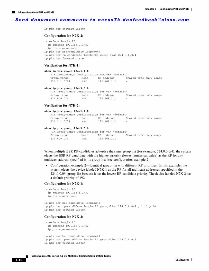
Send document comments to nexus7k -doc feedback@c i sco .com
Chapter 1 Configuring PIM and PIM6Information About PIM and PIM6
ip pim bsr forward listen
Configuration for N7K-2:
interface loopback0 ip address 192.168.2.1/32 ip pim sparse-modeip pim bsr bsr-candidate loopback0 ip pim bsr rp-candidate loopback0 group-list 224.0.0.0/4ip pim bsr forward listen
Verification for N7K-1:
show ip pim group 224.1.1.0 PIM Group-Range Configuration for VRF "default" Group-range Mode RP-address Shared-tree-only range 224.1.1.0/24 ASM 192.168.1.1 -
show ip pim group 224.3.0.0 PIM Group-Range Configuration for VRF "default" Group-range Mode RP-address Shared-tree-only range 224.0.0.0/4 ASM 192.168.2.1 -
Verification for N7K-2:
show ip pim group 224.1.1.0 PIM Group-Range Configuration for VRF "default" Group-range Mode RP-address Shared-tree-only range 224.1.1.0/24 ASM 192.168.1.1 -
show ip pim group 224.3.0.0 PIM Group-Range Configuration for VRF "default" Group-range Mode RP-address Shared-tree-only range 224.0.0.0/4 ASM 192.168.2.1
When multiple BSR RP-candidates advertise the same group list (for example, 224.0.0.0/4), the system elects the BSR RP-candidate with the highest priority (lowest numerical value) as the RP for any multicast address specified in its group-list (see configuration example 2).
• Configuration example 2—Identical group-list with different RP priorities: In this example, the system elects the device labeled N7K-1 as the RP for all multicast addresses specified in the 224.0.0.0/4 group-list because it has the lowest RP-candidate priority. The device labeled N7K-2 has a default priority of 192.
Configuration for N7K-1:
interface loopback0 ip address 192.168.1.1/32 ip pim sparse-mode
ip pim bsr bsr-candidate loopback0ip pim bsr rp-candidate loopback0 group-list 224.0.0.0/4 priority 10ip pim bsr forward listen
Configuration for N7K-2:
interface loopback0 ip address 192.168.2.1/32 ip pim sparse-mode
ip pim bsr bsr-candidate loopback0 ip pim bsr rp-candidate loopback0 group-list 224.0.0.0/4ip pim bsr forward listen
1-10Cisco Nexus 7000 Series NX-OS Multicast Routing Configuration Guide
OL-23238-01

Send document comments to nexus7k -doc feedback@c i sco .com
Chapter 1 Configuring PIM and PIM6Information About PIM and PIM6
Verification for N7K-1:
show ip pim rp PIM RP Status Information for VRF "default" BSR: 192.168.2.1, uptime: 00:09:14, expires: 00:01:37,
priority: 64, hash-length: 30 Auto-RP disabled BSR RP Candidate policy: None BSR RP policy: None Auto-RP Announce policy: None Auto-RP Discovery policy: None
RP: 192.168.1.1*, (0), uptime: 00:08:15, expires: 00:01:57, priority: 10, RP-source: 192.168.2.1 (B), group ranges:
224.0.0.0/4
RP: 192.168.2.1, (0), uptime: 00:08:15, expires: 00:01:57, priority: 192, RP-source: 192.168.2.1 (B), group ranges:
224.0.0.0/4
show ip pim group 224.1.1.0 PIM Group-Range Configuration for VRF "default" Group-range Mode RP-address Shared-tree-only range 224.0.0.0/4 ASM 192.168.1.1
Verification for N7K-2:
show ip pim rp PIM RP Status Information for VRF "default" BSR: 192.168.2.1*, next Bootstrap message in: 00:00:55,
priority: 64, hash-length: 30 Auto-RP disabled BSR RP Candidate policy: None BSR RP policy: None Auto-RP Announce policy: None Auto-RP Discovery policy: None
RP: 192.168.1.1, (0), uptime: 00:11:34, expires: 00:02:26, priority: 10, RP-source: 192.168.1.1 (B), group ranges:
224.0.0.0/4
RP: 192.168.2.1*, (0), uptime: 00:12:21, expires: 00:02:22, priority: 192, RP-source: 192.168.2.1 (B), group ranges:
224.0.0.0/4
show ip pim group 224.1.1.0 PIM Group-Range Configuration for VRF "default" Group-range Mode RP-address Shared-tree-only range 224.0.0.0/4 ASM 192.168.1.1 -
When multiple BSR RP-candidates advertise the same group list (for example, 224.0.0.0/4) and are configured with the same BSR RP-candidate priority, the system elects the BSR RP-candidate with the highest IP address as the RP for any multicast address specified in its group list (see configuration example 3).
• Configuration example 3—Identical group list with identical RP priorities: In this example, the system elects the device labeled N7K-2 as the RP for all multicast addresses specified in the 224.0.0.0/4 group list because it has the highest RP-candidate IP address.
Configuration for N7K-1:
interface loopback0 ip address 192.168.1.1/32
1-11Cisco Nexus 7000 Series NX-OS Multicast Routing Configuration Guide
OL-23238-01

Send document comments to nexus7k -doc feedback@c i sco .com
Chapter 1 Configuring PIM and PIM6Information About PIM and PIM6
ip pim sparse-mode
ip pim bsr bsr-candidate loopback0ip pim bsr rp-candidate loopback0 group-list 224.0.0.0/4ip pim bsr forward listen
Configuration for N7K-2:
interface loopback0 ip address 192.168.2.1/32 ip pim sparse-mode
ip pim bsr bsr-candidate loopback0 ip pim bsr rp-candidate loopback0 group-list 224.0.0.0/4ip pim bsr forward listen
Verification for N7K-1:
show ip pim group 224.1.1.0 PIM Group-Range Configuration for VRF "default" Group-range Mode RP-address Shared-tree-only range 224.0.0.0/4 ASM 192.168.2.1 -
Verification for N7K-2:
show ip pim group 224.1.1.0 PIM Group-Range Configuration for VRF "default" Group-range Mode RP-address Shared-tree-only range 224.0.0.0/4 ASM 192.168.2.1 -
PIM BSR RP-Candidate vs. Static RP Election Process
The RP with the most specific group list is elected as the RP for any multicast addresses specified in its configured group list. The most specific group list takes priority over the highest RP IP address (see configuration example 1). (RP priorities are not applicable when comparing BSR RP-candidates to static RPs.)
• Configuration example 1—Most specific group list: In this example, the system elects the device labeled N7K-1 as the BSR RP for all multicast addresses specified in the 224.1.1.0/24 group-list. The system elects the device labeled N7K-2 as the RP for the multicast addresses within the less specific 224.0.0.0/4 group list because of the static RP statement.
Configuration for N7K-1:
interface loopback0 ip address 192.168.1.1/32 ip pim sparse-mode
ip pim bsr bsr-candidate loopback0ip pim rp-address 192.168.2.1 group-list 224.0.0.0/4 ip pim bsr rp-candidate loopback0 group-list 224.1.1.0/24ip pim forward listen
Configuration for N7K-2:
interface loopback0 ip address 192.168.2.1/32 ip pim sparse-mode
ip pim rp-address 192.168.2.1 group-list 224.0.0.0/4
1-12Cisco Nexus 7000 Series NX-OS Multicast Routing Configuration Guide
OL-23238-01

Send document comments to nexus7k -doc feedback@c i sco .com
Chapter 1 Configuring PIM and PIM6Information About PIM and PIM6
ip pim bsr forward listen
Verification for N7K-1:
show ip pim group 224.1.1.0 PIM Group-Range Configuration for VRF "default" Group-range Mode RP-address Shared-tree-only range 224.1.1.0/24 ASM 192.168.1.1 -
show ip pim group 224.3.0.0 PIM Group-Range Configuration for VRF "default" Group-range Mode RP-address Shared-tree-only range 224.0.0.0/4 ASM 192.168.2.1 -
Verification for N7K-2:
show ip pim group 224.1.1.0 PIM Group-Range Configuration for VRF "default" Group-range Mode RP-address Shared-tree-only range 224.1.1.0/24 ASM 192.168.1.1 -
show ip pim group 224.3.0.0 PIM Group-Range Configuration for VRF "default" Group-range Mode RP-address Shared-tree-only range 224.0.0.0/4 ASM 192.168.2.1 -
When a static RP and the BSR RP-candidate advertise the same group list (for example, 224.0.0.0/4), the system elects the system with the highest RP IP address as the RP for any multicast addresses specified in its group-list (see configuration example 2).
• Configuration example 2—Identical RP group list: In this example, the system elects the device labeled N7K-2 as the RP for all multicast addresses specified in the 224.0.0.0/4 group list because it has the highest RP IP address.
Configuration for N7K-1:
interface loopback0 ip address 192.168.1.1/32 ip pim sparse-mode
ip pim rp-address 192.168.1.1 group-list 224.0.0.0/4
ip pim bsr forward listen
Configuration for N7K-2:
interface loopback0 ip address 192.168.2.1/32 ip pim sparse-mode
ip pim bsr bsr-candidate loopback0ip pim rp-address 192.168.1.1 group-list 224.0.0.0/4 ip pim bsr rp-candidate loopback0 group-list 224.0.0.0/4ip pim bsr forward listen
Verification for N7K-1:
show ip pim group 224.1.1.0 PIM Group-Range Configuration for VRF "default" Group-range Mode RP-address Shared-tree-only range 224.0.0.0/4 ASM 192.168.2.1
Verification for N7K-2:
1-13Cisco Nexus 7000 Series NX-OS Multicast Routing Configuration Guide
OL-23238-01

Send document comments to nexus7k -doc feedback@c i sco .com
Chapter 1 Configuring PIM and PIM6Information About PIM and PIM6
show ip pim group 224.1.1.0 PIM Group-Range Configuration for VRF "default" Group-range Mode RP-address Shared-tree-only range 224.0.0.0/4 ASM 192.168.2.1 -
Because you cannot configure a static RP and its default value is 0, the RP priority has no impact. You can configure the BSR RP-candidate with a value between 0 and 255. The system elects the device with the most specific group list. If both devices have the same group list, the system elects the device with the highest RP IP address (see configuration example 3).
• Configuration example 3—Identical group list and identical RP priorities: In this example, the system elects the device labeled N7K-2 as the RP for all multicast addresses specified in the 224.0.0.0/4 group list because it has the highest RP IP address. The system does not compare RP priorities between BSR RPs and static RPs.
Configuration for N7K-1:
interface loopback0 ip address 192.168.1.1/32 ip pim sparse-mode
ip pim bsr bsr-candidate loopback0 ip pim rp-address 192.168.2.1 group-list 224.0.0.0/4 ip pim bsr rp-candidate loopback0 group-list 224.0.0.0/4 priority 0
ip pim bsr forward listen
Configuration for N7K-2:
interface loopback0 ip address 192.168.2.1/32 ip pim sparse-mode
ip pim rp-address 192.168.2.1 group-list 224.0.0.0/4
ip pim bsr forward listen
Verification for N7K-1:
show ip pim rp PIM RP Status Information for VRF "default" BSR: 192.168.1.1*, next Bootstrap message in: 00:00:52,
priority: 64, hash-length: 30 Auto-RP disabled BSR RP Candidate policy: None BSR RP policy: None Auto-RP Announce policy: None Auto-RP Discovery policy: None
RP: 192.168.1.1*, (0), uptime: 00:01:57, expires: 00:02:25, priority: 0, RP-source: 192.168.1.1 (B), group ranges:
224.0.0.0/4 RP: 192.168.2.1, (0), uptime: 02:16:09, expires: never, priority: 0, RP-source: (local), group ranges:
224.0.0.0/4
show ip pim group 224.1.1.0 PIM Group-Range Configuration for VRF "default" Group-range Mode RP-address Shared-tree-only range 224.0.0.0/4 ASM 192.168.2.1 -
Verification for N7K-2:
show ip pim rp
1-14Cisco Nexus 7000 Series NX-OS Multicast Routing Configuration Guide
OL-23238-01

Send document comments to nexus7k -doc feedback@c i sco .com
Chapter 1 Configuring PIM and PIM6Information About PIM and PIM6
PIM RP Status Information for VRF "default" BSR: 192.168.1.1, uptime: 00:29:47, expires: 00:01:45,
priority: 64, hash-length: 30 Auto-RP disabled BSR RP Candidate policy: None BSR RP policy: None Auto-RP Announce policy: None Auto-RP Discovery policy: None
RP: 192.168.1.1, (0), uptime: 00:06:59, expires: 00:02:05, priority: 0, RP-source: 192.168.1.1 (B), group ranges:
224.0.0.0/4 RP: 192.168.2.1*, (0), uptime: 00:13:15, expires: never, priority: 0, RP-source: (local), group ranges:
224.0.0.0/4
show ip pim group 224.1.1.0 PIM Group-Range Configuration for VRF "default" Group-range Mode RP-address Shared-tree-only range 224.0.0.0/4 ASM 192.168.2.1 -
PIM Auto-RP-Candidate vs. Auto-RP-Candidate Election Process
The auto-RP-candidate election is similar to the BSR RP-candidate election process, but it does not support priorities (see the “PIM BSR RP-Candidate vs. BSR RP-Candidate Election Process” section on page 1-9). You cannot configure the priority for an auto-RP, and the default value is 0.
PIM Auto-RP-Candidate vs. Static RP Election Process
The auto-RP-candidate versus static RP election uses the same rules as the election process for the BSR RP-candidate versus static RP (see “PIM BSR RP-Candidate vs. Static RP Election Process” section on page 1-12).
Anycast-RP
Anycast-RP has two implementations: one uses Multicast Source Discovery Protocol (MSDP) and the other is based on RFC 4610, Anycast-RP Using Protocol Independent Multicast (PIM). This section describes how to configure PIM Anycast-RP.
You can use PIM Anycast-RP to assign a group of routers, called the Anycast-RP set, to a single RP address that is configured on multiple routers. The set of routers that you configure as Anycast-RPs is called the Anycast-RP set. This method is the only RP method that supports more than one RP per multicast group, which allows you to load balance across all RPs in the set. The Anycast RP supports all multicast groups.
PIM register messages are sent to the closest RP and PIM join-prune messages are sent in the direction of the closest RP as determined by the unicast routing protocols. If one of the RPs goes down, unicast routing ensures these message will be sent in the direction of the next-closest RP.
You must configue PIM on the loopback interface that is used for the PIM Anycast RP.
For more information about PIM Anycast-RP, see RFC 4610.
For information about configuring Anycast-RPs, see the “Configuring a PIM Anycast-RP Set” section on page 1-37.
1-15Cisco Nexus 7000 Series NX-OS Multicast Routing Configuration Guide
OL-23238-01

Send document comments to nexus7k -doc feedback@c i sco .com
Chapter 1 Configuring PIM and PIM6Information About PIM and PIM6
PIM Register MessagesPIM register messages are unicast to the RP by designated routers (DRs) that are directly connected to multicast sources. The PIM register message has the following functions:
• To notify the RP that a source is actively sending to a multicast group.
• To deliver multicast packets sent by the source to the RP for delivery down the shared tree.
The DR continues to send PIM register messages to the RP until it receives a Register-Stop message from the RP. The RP sends a Register-Stop message in either of the following cases:
• The RP has no receivers for the multicast group being transmitted.
• The RP has joined the SPT to the source but has not started receiving traffic from the source.
You can use the ip pim register-source command to configure the IP source address of register messages when the IP source address of a register message is not a uniquely routed address to which the RP can send packets. This situation might occur if the source address is filtered so that the packets sent to it are not forwarded or if the source address is not unique to the network. In these cases, the replies sent from the RP to the source address will fail to reach the DR, resulting in Protocol Independent Multicast sparse mode (PIM-SM) protocol failures.
The following example shows how to configure the IP source address of the register message to the loopback 3 interface of a DR:
ip pim register-source loopback 3
Note In Cisco NX-OS, PIM register messages are rate limited to avoid overwhelming the RP.
You can filter PIM register messages by defining a routing policy. For information about configuring the PIM register message policy, see the “Configuring Shared Trees Only for ASM” section on page 1-40.
Designated RoutersIn PIM ASM and SSM modes, the software chooses a designated router (DR) from the routers on each network segment. The DR is responsible for forwarding multicast data for specified groups and sources on that segment.
The DR for each LAN segment is determined as described in the “Hello Messages” section on page 1-3.
In ASM mode, the DR is responsible for unicasting PIM register packets to the RP. When a DR receives an IGMP membership report from a directly connected receiver, the shortest path is formed to the RP, which may or may not go through the DR. The result is a shared tree that connects all sources transmitting on the same multicast group to all receivers of that group.
In SSM mode, the DR triggers (*, G) or (S, G) PIM join messages toward the RP or the source. The path from the receiver to the source is determined hop by hop. The source must be known to the receiver or the DR.
For information about configuring the DR priority, see the “Configuring PIM or PIM6 Sparse Mode” section on page 1-22.
1-16Cisco Nexus 7000 Series NX-OS Multicast Routing Configuration Guide
OL-23238-01

Send document comments to nexus7k -doc feedback@c i sco .com
Chapter 1 Configuring PIM and PIM6Information About PIM and PIM6
Designated ForwardersIn PIM Bidir mode, the software chooses a designated forwarder (DF) at RP discovery time from the routers on each network segment. The DF is responsible for forwarding multicast data for specified groups on that segment. The DF is elected based on the best metric from the network segment to the RP.
If the router receives a packet on the RPF interface toward the RP, the router forwards the packet out all interfaces in the OIF-list. If a router receives a packet on an interface on which the router is the elected DF for that LAN segment, the packet is forwarded out all interfaces in the OIF-list except the interface that it was received on and also out the RPF interface toward the RP.
Note Cisco NX-OS puts the RPF interface into the OIF-list of the MRIB, but not in the OIF-list of the MFIB.
ASM Switchover from Shared Tree to Source TreeIn ASM mode, the DR that is connected to a receiver switches over from the shared tree to the shortest-path tree (SPT) to a source unless you configure the PIM parameter to use shared trees only. For information about configuring the use of shared trees only, see the “Configuring Shared Trees Only for ASM” section on page 1-40.
During the switchover, messages on the SPT and shared tree may overlap. These messages are different. The shared tree messages are propagated upstream toward the RP, while SPT messages go toward the source.
For information about SPT switchovers, see the “Last-Hop Switchover” to the SPT section in RFC 4601.
Administratively Scoped IP MulticastThe administratively scoped IP multicast method allows you to set boundaries on the delivery of multicast data. For more information, see RFC 2365.
You can configure an interface as a PIM boundary so that PIM messages are not sent out that interface. For information about configuring the domain border parameter, see the “Configuring PIM or PIM6 Sparse Mode” section on page 1-22.
You can use the Auto-RP scope parameter to set a time-to-live (TTL) value. For more information, see the “Configuring Shared Trees Only for ASM” section on page 1-40.
Bidirectional Forwarding Detection for PIMBeginning with Cisco NX-OS Release 5.0(2a), Bidirectional Forwarding Detection (BFD) allows the system to rapidly detect failures in a network. See the Cisco Nexus 7000 Series NX-OS Unicast Routing Configuration Guide, Release 5.x for more information about BFD.
In PIM, a link or neighbor group failure is detected when the hold-time, which is set as part of the hello interval, expires. However, BFD provides a more efficient method to detect a failure. This protocol establishes a session between the two endpoints over a link and uses the forwarding engine. When BFD is enabled, the PIM process attempts to add a BFD session as each neighbor is discovered. If a BFD session already exists, no duplicate is created but PIM receives a callback that contains the state of the BFD session. You can enable BFD for PIM per VRF or per interface.
1-17Cisco Nexus 7000 Series NX-OS Multicast Routing Configuration Guide
OL-23238-01

Send document comments to nexus7k -doc feedback@c i sco .com
Chapter 1 Configuring PIM and PIM6Licensing Requirements for PIM and PIM6
PIM removes the BFD session when you disable BFD for that VRF or interface, the interface is no longer a PIM interface, or the neighboring BFD session goes down.
Virtualization SupportA virtual device context (VDC) is a logical representation of a set of system resources. Within each VDC, multiple virtual routing and forwarding (VRF) instances can be defined. For each VRF in a VDC in the system, independent multicast system resources are maintained, including the MRIB and M6RIB.
You can use the PIM and PIM6 show commands with a VRF argument to provide a context for the information displayed. The default VRF is used if no VRF argument is supplied.
For information about configuring VDCs, see the Cisco Nexus 7000 Series NX-OS Virtual Device Context Configuration Guide, Release 4.2.
For information about configuring VRFs, see the Cisco Nexus 7000 Series NX-OS Unicast Routing Configuration Guide, Release 5.x.
High AvailabilityFor information about high availability, see the Cisco Nexus 7000 Series NX-OS High Availability and Redundancy Guide, Release 5.x.
Licensing Requirements for PIM and PIM6The following table shows the licensing requirements for this feature:
Prerequisites for PIM and PIM6PIM and PIM6 have the following prerequisites:
• You are logged onto the device.
• You are in the correct virtual device context (VDC). A VDC is a logical representation of a set of system resources. You can use the switchto vdc command with a VDC number.
• For global commands, you are in the correct virtual routing and forwarding (VRF) mode. The default configuration mode shown in the examples in this chapter applies to the default VRF.
Guidelines and Limitations for PIM and PIM6PIM and PIM6 have the following guidelines and limitations:
Product License Requirement
Cisco NX-OS PIM and PIM6 require an Enterprise Services license. For a complete explanation of the Cisco NX-OS licensing scheme and how to obtain and apply licenses, see the Cisco NX-OS Licensing Guide.
1-18Cisco Nexus 7000 Series NX-OS Multicast Routing Configuration Guide
OL-23238-01

Send document comments to nexus7k -doc feedback@c i sco .com
Chapter 1 Configuring PIM and PIM6Default Settings
• Tunnel interfaces do not support PIM until Cisco NX-OS Release 5.2(1). Beginning with Release 5.2(1), you can configure multicast on GRE tunnel interfaces.
• Cisco NX-OS PIM and PIM6 do not interoperate with any version of PIM dense mode or PIM sparse mode version 1.
• Do not configure both Auto-RP and BSR protocols in the same network.
• Configure candidate RP intervals to a minimum of 15 seconds.
• If a device is configured with a BSR policy that should prevent it from being elected as the BSR, the device ignores the policy. This behavior results in the following undesirable conditions:
– If a device receives a BSM that is permitted by the policy, the device, which incorrectly elected itself as the BSR, drops that BSM so that routers downstream fail to receive it. Downstream devices correctly filter the BSM from the incorrect BSR so that these devices do not receive RP information.
– A BSM received by a BSR from a different device sends a new BSM but ensures that downstream devices do not receive the correct BSM.
• While using avirtual port channel (vPC) with dual supervisors, you must use the default timers as follows:
– While using dual supervisors where we recommend high default timer values; convergence will suffer on a link failure. If you want to perform ISSU or you want the system to do an SSO without any network reconvergence, you must specify higher default timer values.
– Beginning with Release 5.x, we recommend that you use BFD for PIM instead of nondefault timers.
• Default PIM timer values are recommended for most deployments. ISSU/SSO may not function as expected if timers are modified from the default values.
• Beginning with Release 5.x, we recommend that you use BFD for PIM to support subsecond failure detection.
Default SettingsTable 1-2 lists the default settings for PIM and PIM6 parameters.
Table 1-2 Default PIM and PIM6 Parameters
Parameters Default
Use shared trees only Disabled
Flush routes on restart Disabled
Log Neighbor changes Disabled
Auto-RP message action Disabled
BSR message action Disabled
SSM multicast group range or policy 232.0.0.0/8 for IPv4 and FF3x::/96 for IPv6
PIM sparse mode Disabled
Designated router priority 0
Hello authentication mode Disabled
Domain border Disabled
1-19Cisco Nexus 7000 Series NX-OS Multicast Routing Configuration Guide
OL-23238-01

Send document comments to nexus7k -doc feedback@c i sco .com
Chapter 1 Configuring PIM and PIM6Configuring PIM and PIM6
Configuring PIM and PIM6You can configure both PIM and PIM6 on the same router. You configure either PIM or PIM6 for each interface, depending on whether that interface is running IPv4 or IPv6.
Note Cisco NX-OS supports only PIM sparse mode version 2. In this publication, “PIM” refers to PIM sparse mode version 2.
You can configure separate ranges of addresses in the PIM or PIM6 domain using the multicast distribution modes described in Table 1-3.
To configure PIM and PIM6, follow these steps:
Step 1 From the multicast distribution modes described in Table 1-3, select the range of multicast groups that you want to configure in each mode.
Step 2 Enable the PIM and PIM6 features. See the “Enabling the PIM and PIM6 Features” section on page 1-21.
Step 3 Configure PIM or PIM6 sparse mode on each interface that you want to participate in a PIM domain. See the “Configuring PIM or PIM6 Sparse Mode” section on page 1-22.
Step 4 Follow the configuration steps for the multicast distribution modes that you selected in Step 1 as follows:
• For ASM or Bidir mode, see the “Configuring ASM and Bidir” section on page 1-29.
RP address policy No message filtering
PIM register message policy No message filtering
BSR candidate RP policy No message filtering
BSR policy No message filtering
Auto-RP mapping agent policy No message filtering
Auto-RP RP candidate policy No message filtering
Join-prune policy No message filtering
Neighbor adjacency policy Become adjacent with all PIM neighbors
BFD Disabled
Table 1-2 Default PIM and PIM6 Parameters (continued)
Parameters Default
Table 1-3 PIM and PIM6 Multicast Distribution Modes
Multicast Distribution Mode
Requires RP Configuration Description
ASM Yes Any source multicast
Bidir Yes Bidirectional shared trees
SSM No Single source multicast
RPF routes for multicast
No RPF routes for multicast
1-20Cisco Nexus 7000 Series NX-OS Multicast Routing Configuration Guide
OL-23238-01

Send document comments to nexus7k -doc feedback@c i sco .com
Chapter 1 Configuring PIM and PIM6Configuring PIM and PIM6
• For SSM mode, see the “Configuring SSM” section on page 1-42.
• For RPF routes for multicast, see the “Configuring RPF Routes for Multicast” section on page 1-44.
Step 5 Configure message filtering. See the “Configuring Message Filtering” section on page 1-48.
The CLI commands used to configure PIM or PIM6 differ as follows:
• Commands begin with ip pim for PIM and begin with ipv6 pim for PIM6.
• Commands begin with show ip pim for PIM and begin with show ipv6 pim for PIM6.
This section includes the following topics:
• Enabling the PIM and PIM6 Features, page 1-21
• Configuring PIM or PIM6 Sparse Mode, page 1-22
• Configuring ASM and Bidir, page 1-29
• Configuring SSM, page 1-42
• Configuring RPF Routes for Multicast, page 1-44
• Configuring Route Maps to Control RP Information Distribution, page 1-45
• Configuring Message Filtering, page 1-48
• Restarting the PIM and PIM6 Processes, page 1-52
• Configuring BFD for PIM, page 1-54
Note If you are familiar with the Cisco IOS CLI, be aware that the Cisco NX-OS commands for this feature might differ from the Cisco IOS commands that you would use.
Enabling the PIM and PIM6 FeaturesBefore you can access the PIM or PIM6 commands, you must enable the PIM or PIM6 feature.
BEFORE YOU BEGIN
Ensure that you have installed the Enterprise Services license.
SUMMARY STEPS
1. config t
2. feature pim
3. feature pim6
4. (Optional) show running-configuration pim
5. (Optional) show running-configuration pim6
6. (Optional) copy running-config startup-config
1-21Cisco Nexus 7000 Series NX-OS Multicast Routing Configuration Guide
OL-23238-01

Send document comments to nexus7k -doc feedback@c i sco .com
Chapter 1 Configuring PIM and PIM6Configuring PIM and PIM6
DETAILED STEPS
Configuring PIM or PIM6 Sparse ModeYou configure PIM or PIM6 sparse mode on every device interface that you want to participate in a sparse mode domain. You can configure the sparse mode parameters described in Table 1-4.
Command Purpose
Step 1 config t
Example:switch# config tswitch(config)#
Enters configuration mode.
Step 2 feature pim
Example:switch(config)# feature pim
Enables PIM. By default, PIM is disabled.
Step 3 feature pim6
Example:switch(config)# feature pim6
Enables PIM6. By default, PIM6 is disabled.
Step 4 show running-configuration pim
Example:switch(config)# show running-configuration pim
(Optional) Shows the running-configuration information for PIM, including the feature command.
Step 5 show running-configuration pim6
Example:switch(config)# show running-configuration pim6
(Optional) Shows the running-configuration information for PIM6, including the feature command.
Step 6 copy running-config startup-config
Example:switch(config)# copy running-config startup-config
(Optional) Saves configuration changes.
Table 1-4 PIM and PIM6 Sparse Mode Parameters
Parameter Description
Global to the device
Auto-RP message action
Enables listening and forwarding of Auto-RP messages. The default is disabled, which means that the router does not listen or forward Auto-RP messages unless it is configured as a candidate RP or mapping agent.
Note PIM6 does not support the Auto-RP method.
BSR message action Enables listening and forwarding of BSR messages. The default is disabled, which means that the router does not listen or forward BSR messages unless it is configured as a candidate RP or BSR candidate.
1-22Cisco Nexus 7000 Series NX-OS Multicast Routing Configuration Guide
OL-23238-01

Send document comments to nexus7k -doc feedback@c i sco .com
Chapter 1 Configuring PIM and PIM6Configuring PIM and PIM6
Bidir RP limit Configures the number of Bidir RPs that you can configure for IPv4 and IPv6. The maximum number of Bidir RPs supported per VRF for PIM and PIM6 combined cannot exceed 8. Values range from 0 to 8. The default is 6 for IPv4 and 2 for IPv6.
Register rate limit Configures the IPv4 or IPv6 register rate limit in packets per second. The range is from 1 to 65,535. The default is no limit.
Initial holddown period Configures the IPv4 or IPv6 initial holddown period in seconds. This holddown period is the time it takes for the MRIB to come up initially. If you want faster convergence, enter a lower value. The range is from 90 to 210. Specify 0 to disable the holddown period. The default is 210.
Per device interface
PIM sparse mode Enables PIM or PIM6 on an interface.
Designated router priority
Sets the designated router (DR) priority that is advertised in PIM hello messages on this interface. On a multi-access network with multiple PIM-enabled routers, the router with the highest DR priority is elected as the DR router. If the priorities match, the software elects the DR with the highest IP address. The DR originates PIM register messages for the directly connected multicast sources and sends PIM join messages toward the rendezvous point (RP) for directly connected receivers. Values range from 1 to 4294967295. The default is 1.
Hello authentication mode
Enables an MD5 hash authentication key, or password, in PIM hello messages on the interface so that directly connected neighbors can authenticate each other. The PIM hello messages are IPsec encoded using the Authentication Header (AH) option. You can enter an unencrypted (cleartext) key or one of these values followed by a space and the MD5 authentication key:
• 0—Specifies an unencrypted (cleartext) key
• 3—Specifies a 3-DES encrypted key
• 7—Specifies a Cisco Type 7 encrypted key
The authentication key can be up to 16 characters. The default is disabled.
Note PIM6 does not support hello authentication.
Hello interval Configures the interval at which hello messages are sent in milliseconds. The range is from 1 to 4294967295. The default is 30000.
Table 1-4 PIM and PIM6 Sparse Mode Parameters (continued)
Parameter Description
1-23Cisco Nexus 7000 Series NX-OS Multicast Routing Configuration Guide
OL-23238-01

Send document comments to nexus7k -doc feedback@c i sco .com
Chapter 1 Configuring PIM and PIM6Configuring PIM and PIM6
For information about configuring multicast route maps, see the “Configuring Route Maps to Control RP Information Distribution” section on page 1-45.
Note To configure the join-prune policy, see the “Configuring Message Filtering” section on page 1-48.
BEFORE YOU BEGIN
Ensure that you have installed the Enterprise Services license and enabled PIM or PIM6.
SUMMARY STEPS
PIM Commands
1. config t
2. (Optional) ip pim auto-rp {listen [forward] | forward [listen]}
3. (Optional) ip pim bsr {listen [forward] | forward [listen]}
4. (Optional) show ip pim rp [ip-prefix] [vrf vrf-name | all]
5. (Optional) ip pim bidir-rp-limit limit
6. (Optional) ip pim register-rate-limit rate
7. (Optional) [ip | ipv4] routing multicast holddown holddown-period
8. show running-configuration pim
9. interface interface
10. ip pim sparse-mode
11. (Optional) ip pim dr-priority priority
12. (Optional) ip pim hello-authentication ah-md5 auth-key
13. (Optional) ip pim hello-interval interval
14. (Optional) ip pim border
Domain border Enables the interface to be on the border of a PIM domain so that no bootstrap, candidate-RP, or Auto-RP messages are sent or received on the interface. The default is disabled.
Note PIM6 does not support the Auto-RP method.
Neighbor policy Configures which PIM neighbors to become adjacent to based on a route-map policy1 where you can specify IP addresses to become adjacent to with the match ip[v6] address command. If the policy name does not exist, or no IP addresses are configured in a policy, adjacency is established with all neighbors. The default is to become adjacent with all PIM neighbors.
Note We recommend that you should configure this feature only if you are an experienced network administrator.
1. To configure route-map policies, see the Cisco Nexus 7000 Series NX-OS Unicast Routing Configuration Guide, Release 5.x.
Table 1-4 PIM and PIM6 Sparse Mode Parameters (continued)
Parameter Description
1-24Cisco Nexus 7000 Series NX-OS Multicast Routing Configuration Guide
OL-23238-01

Send document comments to nexus7k -doc feedback@c i sco .com
Chapter 1 Configuring PIM and PIM6Configuring PIM and PIM6
15. (Optional) ip pim neighbor-policy policy-name
16. (Optional) show ip pim interface [interface | brief] [vrf vrf-name | all]
17. (Optional) copy running-config startup-config
PIM6 Commands
1. config t
2. (Optional) ipv6 pim bsr {listen [forward] | forward [listen]}
3. (Optional) show ipv6 pim rp [ipv6-prefix] [vrf vrf-name | all]
4. (Optional) ipv6 pim bidir-rp-limit limit
5. (Optional) ipv6 pim register-rate-limit rate
6. (Optional) ipv6 routing multicast holddown holddown-period
7. show running-configuration pim6
8. interface interface
9. ipv6 pim sparse-mode
10. (Optional) ipv6 pim dr-priority priority
11. (Optional) ipv6 pim hello-interval interval
12. (Optional) ipv6 pim border
13. (Optional) ipv6 pim neighbor-policy policy-name
14. (Optional) show ipv6 pim interface [interface | brief] [vrf vrf-name | all]
15. (Optional) copy running-config startup-config
DETAILED STEPS
PIM Commands
Command Purpose
Step 1 config t
Example:switch# config tswitch(config)#
Enters configuration mode.
Step 2 ip pim auto-rp {listen [forward] | forward [listen]}
Example:switch(config)# ip pim auto-rp listen
(Optional) Enables listening or forwarding of Auto-RP messages. The default is disabled, which means that the software does not listen to or forward Auto-RP messages.
Step 3 ip pim bsr {listen [forward] | forward [listen]}
Example:switch(config)# ip pim bsr forward
(Optional) Enables listening or forwarding of BSR messages. The default is disabled, which means that the software does not listen or forward BSR messages.
Step 4 show ip pim rp [ip-prefix] [vrf vrf-name | all]
Example:switch(config)# show ip pim rp
(Optional) Displays PIM RP information, including Auto-RP and BSR listen and forward states.
1-25Cisco Nexus 7000 Series NX-OS Multicast Routing Configuration Guide
OL-23238-01

Send document comments to nexus7k -doc feedback@c i sco .com
Chapter 1 Configuring PIM and PIM6Configuring PIM and PIM6
Step 5 ip pim bidir-rp-limit limit
Example:switch(config)# ip pim bidir-rp-limit 4
(Optional) Specifies the number of Bidir RPs that you can configure for IPv4. The maximum number of Bidir RPs supported per VRF for PIM and PIM6 combined cannot exceed 8. Values range from 0 to 8. The default is 6.
Step 6 ip pim register-rate-limit rate
Example:switch(config)# ip pim register-rate-limit 1000
(Optional) Configures the rate limit in packets per second. The range is from 1 to 65,535. The default is no limit.
Step 7 [ip | ipv4] routing multicast holddown holddown-period
Example:switch(config)# ip routing multicast holddown 100
(Optional) Configures the initial holddown period in seconds. The range is from 90 to 210. Specify 0 to disable the holddown period. The default is 210.
Step 8 show running-configuration pim
Example:switch(config)# show running-configuration pim
(Optional) Displays PIM running-configuration information, including the Bidir RP limit and register rate limit.
Step 9 interface interface
Example:switch(config)# interface ethernet 2/1switch(config-if)#
Enters interface mode on the interface type and number, such as ethernet slot/port.
Step 10 ip pim sparse-mode
Example:switch(config-if)# ip pim sparse-mode
Enables PIM sparse mode on this interface. The default is disabled.
Step 11 ip pim dr-priority priority
Example:switch(config-if)# ip pim dr-priority 192
(Optional) Sets the designated router (DR) priority that is advertised in PIM hello messages. Values range from 1 to 4294967295. The default is 1.
Step 12 ip pim hello-authentication ah-md5 auth-key
Example:switch(config-if)# ip pim hello-authentication ah-md5 my_key
(Optional) Enables an MD5 hash authentication key in PIM hello messages. You can enter an unencrypted (cleartext) key or one of these values followed by a space and the MD5 authentication key:
• 0—Specifies an unencrypted (cleartext) key
• 3—Specifies a 3-DES encrypted key
• 7—Specifies a Cisco Type 7 encrypted key
The key can be up to 16 characters. The default is disabled.
Step 13 ip pim hello-interval interval
Example:switch(config-if)# ip pim hello-interval 25000
(Optional) Configures the interval at which hello messages are sent in milliseconds. The range is from 1000 to 18724286. The default is 30000.
Note Before Cisco NX-OS Release 5.2(1), the minimum value was 1 millisecond.
Command Purpose
1-26Cisco Nexus 7000 Series NX-OS Multicast Routing Configuration Guide
OL-23238-01

Send document comments to nexus7k -doc feedback@c i sco .com
Chapter 1 Configuring PIM and PIM6Configuring PIM and PIM6
PIM6 Commands
Step 14 ip pim border
Example:switch(config-if)# ip pim border
(Optional) Enables the interface to be on the border of a PIM domain so that no bootstrap, candidate-RP, or Auto-RP messages are sent or received on the interface. The default is disabled.
Step 15 ip pim neighbor-policy policy-name
Example:switch(config-if)# ip pim neighbor-policy my_neighbor_policy
(Optional) Configures which PIM neighbors to become adjacent to based on a route-map policy with the match ip address command. The policy name can be up to 63 characters. The default is to become adjacent with all PIM neighbors.
Note We recommend that you should configure this feature only if you are an experienced network administrator.
Step 16 show ip pim interface [interface | brief] [vrf vrf-name | all]
Example:switch(config-if)# show ip pim interface
(Optional) Displays PIM interface information.
Step 17 copy running-config startup-config
Example:switch(config-if)# copy running-config startup-config
(Optional) Saves configuration changes.
Command Purpose
Command Purpose
Step 1 config t
Example:switch# config tswitch(config)#
Enters configuration mode.
Step 2 ipv6 pim bsr {listen [forward] | forward [listen]}
Example:switch(config)# ipv6 pim bsr forward
(Optional) Enables listening or forwarding of BSR messages. The default is disabled, which means that the software does not listen or forward BSR messages.
Step 3 show ipv6 pim rp [ipv6-prefix] [vrf vrf-name | all]
Example:switch(config)# show ipv6 pim rp
(Optional) Displays PIM6 RP information, including BSR listen and forward states.
Step 4 ipv6 pim bidir-rp-limit limit
Example:switch(config)# ipv6 pim bidir-rp-limit 4
(Optional) Specifies the number of Bidir RPs that you can configure for IPv6. The maximum number of Bidir RPs supported per VRF for PIM and PIM6 combined cannot exceed 8. Values range from 0 to 8. The default is 2.
Step 5 ipv6 pim register-rate-limit rate
Example:switch(config)# ipv6 pim register-rate-limit 1000
(Optional) Configures the rate limit in packets per second. The range is from 1 to 65,535. The default is no limit.
1-27Cisco Nexus 7000 Series NX-OS Multicast Routing Configuration Guide
OL-23238-01

Send document comments to nexus7k -doc feedback@c i sco .com
Chapter 1 Configuring PIM and PIM6Configuring PIM and PIM6
Step 6 ipv6 routing multicast holddown holddown-period
Example:switch(config)# ipv6 routing multicast holddown 100
(Optional) Configures the initial holddown period in seconds. The range is from 90 to 210. Specify 0 to disable the holddown period. The default is 210.
Step 7 show running-configuration pim6
Example:switch(config)# show running-configuration pim6
(Optional) Displays PIM6 running-configuration information, including the Bidir RP limit and register rate limit.
Step 8 interface interface
Example:switch(config)# interface ethernet 2/1switch(config-if)#
Enters interface mode on the specified interface.
Step 9 ipv6 pim sparse-mode
Example:switch(config-if)# ipv6 pim sparse-mode
Enables PIM6 sparse mode on this interface. The default is disabled.
Step 10 ipv6 pim dr-priority priority
Example:switch(config-if)# ipv6 pim dr-priority 192
(Optional) Sets the designated router (DR) priority that is advertised in PIM6 hello messages. Values range from 1 to 4294967295. The default is 1.
Step 11 ipv6 pim hello-interval interval
Example:switch(config-if)# ipv6 pim hello-interval 25000
(Optional) Configures the interval at which hello messages are sent in milliseconds. The range is from 1000 to 18724286. The default is 30000.
Note Before Cisco NX-OS Release 5.2(1), the minimum value was 1 millisecond.
Step 12 ipv6 pim border
Example:switch(config-if)# ipv6 pim border
(Optional) Enables the interface to be on the border of a PIM6 domain so that no bootstrap, candidate-RP, or Auto-RP messages are sent or received on the interface. The default is disabled.
Step 13 ipv6 pim neighbor-policy policy-name
Example:switch(config-if)# ipv6 pim neighbor-policy my_neighbor_policy
(Optional) Configures which PIM6 neighbors to become adjacent to based on a route-map policy with the match ipv6 address command. The policy name can be up to 63 characters. The default is to become adjacent with all PIM6 neighbors.
Note We recommend that you should configure this feature only if you are an experienced network administrator.
Step 14 show ipv6 pim interface [interface | brief] [vrf vrf-name | all]
Example:switch(config-if)# show ipv6 pim interface
(Optional) Displays PIM6 interface information.
Step 15 copy running-config startup-config
Example:switch(config-if)# copy running-config startup-config
(Optional) Saves configuration changes.
Command Purpose
1-28Cisco Nexus 7000 Series NX-OS Multicast Routing Configuration Guide
OL-23238-01

Send document comments to nexus7k -doc feedback@c i sco .com
Chapter 1 Configuring PIM and PIM6Configuring PIM and PIM6
Configuring ASM and BidirAny Source Multicast (ASM) and bidirectional shared trees (Bidir) are multicast distribution modes that require the use of RPs to act as a shared root between sources and receivers of multicast data.
To configure ASM or Bidir mode, you configure sparse mode and the RP selection method, where you indicate the distribution mode and assign the range of multicast groups.
Note Bidir mode is not supported for vPCs. For more information about vPCs, see the Cisco Nexus 7000 Series NX-OS Interfaces Configuration Guide, Release 5.x.
This section includes the following topics:
• Configuring Static RPs, page 1-29
• Configuring BSRs, page 1-31
• Configuring Auto-RP, page 1-35
• Configuring a PIM Anycast-RP Set, page 1-37
• Configuring Shared Trees Only for ASM, page 1-40
Configuring Static RPs
You can configure an RP statically by configuring the RP address on every router that will participate in the PIM domain.
You can specify a route-map policy name that lists the group prefixes to use with the match ip multicast command.
Beginning with Cisco NX-OS Release 5.1(3), the ip pim rp-address command has been enhanced with the following functionalities:
• Added prefix-list method of configuration in addition to existing route-map method.
• Added support for policy actions (route-map or prefix-list).
Note Cisco NX-OS always uses the longest-match prefix to find the RP. So, the behavior is the same irrespective of the position of the group prefix in the route map or in the prefix list.
The following example configuration produce the same output using Cisco NX-OS (231.1.1.0/24 is always denied irrespective of the sequence number):
ip prefix-list plist seq 10 deny 231.1.1.0/24ip prefix-list plist seq 20 permit 231.1.0.0/16
ip prefix-list plist seq 10 permit 231.1.0.0/16ip prefix-list plist seq 20 deny 231.1.1.0/24
This behavior differs from Cisco IOS. See the Cisco Nexus 7000 Series NX-OS Multicast Routing Command Reference, Release 5.x, behavior for more samples for the ip pim rp-address command.
BEFORE YOU BEGIN
Ensure that you have installed the Enterprise Services license and enabled PIM or PIM6.
1-29Cisco Nexus 7000 Series NX-OS Multicast Routing Configuration Guide
OL-23238-01

Send document comments to nexus7k -doc feedback@c i sco .com
Chapter 1 Configuring PIM and PIM6Configuring PIM and PIM6
SUMMARY STEPS
PIM Commands
1. config t
2. ip pim rp-address rp-address [group-list ip-prefix | route-map policy-name] [bidir]
3. (Optional) show ip pim group-range [ip-prefix] [vrf vrf-name | all]
4. (Optional) copy running-config startup-config
PIM6 Commands
1. config t
2. ipv6 pim rp-address rp-address [group-list ipv6-prefix | route-map policy-name] [bidir]
3. (Optional) show ipv6 pim group-range [ipv6-prefix] [vrf vrf-name | all]
4. (Optional) copy running-config startup-config
DETAILED STEPS
PIM Commands
Command Purpose
Step 1 config t
Example:switch# config tswitch(config)#
Enters configuration mode.
Step 2 ip pim rp-address rp-address [group-list ip-prefix | route-map policy-name] [bidir]
Example 1:switch(config)# ip pim rp-address 192.0.2.33 group-list 224.0.0.0/9
Example 2:switch(config)# ip pim rp-address 192.0.2.34 group-list 224.128.0.0/9 bidir
Configures a PIM static RP address for a multicast group range. You can specify a route-map policy name that lists the group prefixes to use with the match ip multicast command. The default mode is ASM unless you specify the bidir keyword. The default group range is 224.0.0.0 through 239.255.255.255.
Example 1 configures PIM ASM mode for the specified group range.
Example 2 configures PIM Bidir mode for the specified group range.
Step 3 show ip pim group-range [ip-prefix] [vrf vrf-name | all]
Example:switch(config)# show ip pim group-range
(Optional) Displays PIM modes and group ranges.
Step 4 copy running-config startup-config
Example:switch(config)# copy running-config startup-config
(Optional) Saves configuration changes.
1-30Cisco Nexus 7000 Series NX-OS Multicast Routing Configuration Guide
OL-23238-01

Send document comments to nexus7k -doc feedback@c i sco .com
Chapter 1 Configuring PIM and PIM6Configuring PIM and PIM6
PIM6 Commands
Configuring BSRs
You configure BSRs by selecting candidate BSRs and RPs.
Caution Do not configure both Auto-RP and BSR protocols in the same network.
You can configure a candidate BSR with the arguments described in Table 1-5.
Command Purpose
Step 1 config t
Example:switch# config tswitch(config)#
Enters configuration mode.
Step 2 ipv6 pim rp-address rp-address [group-list ipv6-prefix | route-map policy-name] [bidir]
Example 1:switch(config)# ipv6 pim rp-address 2001:0db8:0:abcd::1 group-list ff1e:abcd:def1::0/24
Example 2:switch(config)# ipv6 pim rp-address 2001:0db8:0:abcd::2 group-list ff1e:abcd:def2::0/96 bidir
Configures a PIM6 static RP address for a multicast group range. You can specify a route-map policy name that lists the group prefixes to use with the match ip multicast command. The mode is ASM unless you specify the bidir keyword. The default group range is ff00::0/8.
Example 1 configures PIM6 ASM mode for the specified group range.
Example 2 configures PIM6 Bidir mode for the specified group range.
Step 3 show ipv6 pim group-range [ipv6-prefix] [vrf vrf-name | all]
Example:switch(config)# show ipv6 pim group-range
(Optional) Displays PIM6 modes and group ranges.
Step 4 copy running-config startup-config
Example:switch(config)# copy running-config startup-config
(Optional) Saves configuration changes.
Table 1-5 Candidate BSR Arguments
Argument Description
interface Interface type and number used to derive the BSR source IP address used in bootstrap messages.
hash-length Number of high order 1s used to form a mask that is ANDed with group address ranges of candidate RPs to form a hash value. The mask determines the number of consecutive addresses to assign across RPs with the same group range. For PIM, this value ranges from 0 to 32 and has a default of 30. For PIM6, this value ranges from 0 to 128 and has a default of 126.
priority Priority assigned to this BSR. The software elects the BSR with the highest priority, or if the BSR priorities match, the software elects the BSR with the highest IP address. This value ranges from 0, the lowest priority, to 255 and has a default of 64.
1-31Cisco Nexus 7000 Series NX-OS Multicast Routing Configuration Guide
OL-23238-01

Send document comments to nexus7k -doc feedback@c i sco .com
Chapter 1 Configuring PIM and PIM6Configuring PIM and PIM6
You can configure a candidate RP with the arguments and keywords described in Table 1-6.
Tip You should choose the candidate BSRs and candidate RPs that have good connectivity to all parts of the PIM domain.
You can configure the same router to be both a BSR and a candidate RP. In a domain with many routers, you can select multiple candidate BSRs and RPs to automatically fail over to alternates if a BSR or an RP fails.
To configure candidate BSRs and RPs, follow these steps:
Step 1 Configure whether each router in the PIM domain should listen and forward BSR messages. A router configured as either a candidate RP or a candidate BSR will automatically listen to and forward all bootstrap router protocol messages, unless an interface is configured with the domain border feature. For more information, see the “Configuring PIM or PIM6 Sparse Mode” section on page 1-22.
Step 2 Select the routers to act as candidate BSRs and RPs.
Step 3 Configure each candidate BSR and candidate RP as described in this section.
Step 4 Configure BSR message filtering. See the “Configuring Message Filtering” section on page 1-48.
BEFORE YOU BEGIN
Ensure that you have installed the Enterprise Services license and enabled PIM or PIM6.
Table 1-6 BSR Candidate RP Arguments and Keywords
Argument or Keyword Description
interface Interface type and number used to derive the BSR source IP address used in Bootstrap messages.
group-list ip-prefix
Multicast groups handled by this RP specified in a prefix format.
interval Number of seconds between sending candidate-RP messages. This value ranges from 1 to 65,535 and has a default of 60 seconds.
Note We recommend that you configure the candidate RP interval to a minimum of 15 seconds.
priority Priority assigned to this RP. The software elects the RP with the highest priority for a range of groups, or if the priorities match, the highest IP address. (The highest priority is the lowest numerical value.) This value ranges from 0, the highest priority, to 255 and has a default of 192.
Note This priority differs from the BSR BSR-candidate priority, which prefers the highest value between 0 and 255.
bidir Unless you specify bidir, this RP will be in ASM mode. If you specify bidir, the RP will be in Bidir mode.
route-map policy-name
Route-map policy name that defines the group prefixes where this feature is applied.
1-32Cisco Nexus 7000 Series NX-OS Multicast Routing Configuration Guide
OL-23238-01

Send document comments to nexus7k -doc feedback@c i sco .com
Chapter 1 Configuring PIM and PIM6Configuring PIM and PIM6
SUMMARY STEPS
PIM Commands
1. config t
2. ip pim bsr listen forward
3. ip pim [bsr] bsr-candidate interface [hash-len hash-length] [priority priority]
4. ip pim [bsr] rp-candidate interface {group-list ip-prefix | route-map policy-name}[priority priority] [interval interval] [bidir]
5. (Optional) show ip pim group-range [ip-prefix] [vrf vrf-name | all]
6. (Optional) copy running-config startup-config
PIM6 Commands
1. config t
2. ipv6 pim [bsr] bsr-candidate interface [hash-len hash-length] [priority priority]
3. ipv6 pim [bsr] rp-candidate interface {group-list ipv6-prefix | route-map policy-name} [priority priority] [interval interval] [bidir]
4. (Optional) show ipv6 pim group-range [ipv6-prefix] [vrf vrf-name | all]
5. (Optional) copy running-config startup-config
DETAILED STEPS
PIM Commands
Command Purpose
Step 1 config t
Example:switch# config tswitch(config)#
Enters configuration mode.
Step 2 ip pim bsr listen forward
Example:switch(config)# ip pim bsr listen forward
Configures listen and forward.
Ensure that you have entered this command in each VRF on the remote PE.
Step 3 ip pim [bsr] bsr-candidate interface [hash-len hash-length] [priority priority]
Example:switch(config)# ip pim bsr-candidate ethernet 2/1 hash-len 24
Configures a candidate bootstrap router (BSR). The source IP address used in a bootstrap message is the IP address of the interface. The hash length ranges from 0 to 32 and has a default of 30. The priority ranges from 0 to 255 and has a default of 64. For parameter details, see Table 1-5.
1-33Cisco Nexus 7000 Series NX-OS Multicast Routing Configuration Guide
OL-23238-01

Send document comments to nexus7k -doc feedback@c i sco .com
Chapter 1 Configuring PIM and PIM6Configuring PIM and PIM6
PIM6 Commands
Step 4 ip pim [bsr] rp-candidate interface {group-list ip-prefix | route-map policy-name} [priority priority] [interval interval] [bidir]
Example 1:switch(config)# ip pim rp-candidate ethernet 2/1 group-list 239.0.0.0/24
Example 2:switch(config)# ip pim rp-candidate ethernet 2/1 group-list 239.0.0.0/24 bidir
Configures a candidate RP for BSR. The priority ranges from 0, the highest priority, to 65,535 and has a default of 192. The interval ranges from 1 to 65,535 seconds and has a default of 60.
Note We recommend that you configure the candidate RP interval to a minimum of 15 seconds.
Example 1 configures an ASM candidate RP.
Example 2 configures a Bidir candidate RP.
Step 5 show ip pim group-range [ip-prefix] [vrf vrf-name | all]
Example:switch(config)# show ip pim group-range
(Optional) Displays PIM modes and group ranges.
Step 6 copy running-config startup-config
Example:switch(config)# copy running-config startup-config
(Optional) Saves configuration changes.
Command Purpose
Command Purpose
Step 1 config t
Example:switch# config tswitch(config)#
Enters configuration mode.
Step 2 ipv6 pim [bsr] bsr-candidate interface [hash-len hash-length] [priority priority]
Example:switch(config)# ipv6 pim bsr-candidate ethernet 2/1 hash-len 24 priority 192
Configures a candidate bootstrap router (BSR). The source IP address used in a bootstrap message is the IP address of the interface. The hash length ranges from 0 to 128 and has a default of 126. The priority ranges from 0, the lowest priority, to 255 and has a default of 64. For parameter details, see Table 1-5.
Step 3 ipv6 pim [bsr] rp-candidate interface {group-list ipv6-prefix | route-map policy-name} [priority priority] [interval interval] [bidir]
Example 1:switch(config)# ipv6 pim rp-candidate ethernet 2/1 group-list ff1e:abcd:def1::0/24
Example 2:switch(config)# ipv6 pim rp-candidate ethernet 2/1 group-list ff1e:abcd:def2::0/24 bidir
Configures a candidate RP for BSR. The priority ranges from 0, the highest priority, to 65,535 and has a default of 192. The interval ranges from 1 to 65,535 seconds and has a default of 60. For parameter details, see Table 1-6.
Example 1 configures an ASM candidate RP.
Example 2 configures a Bidir candidate RP.
1-34Cisco Nexus 7000 Series NX-OS Multicast Routing Configuration Guide
OL-23238-01

Send document comments to nexus7k -doc feedback@c i sco .com
Chapter 1 Configuring PIM and PIM6Configuring PIM and PIM6
Use the show ipv6 pim group-range command to display the configured PIM6 modes and group ranges.
Configuring Auto-RP
You can configure Auto-RP by selecting candidate mapping agents and RPs. You can configure the same router to be both a mapping agent and a candidate RP.
Note Auto-RP is not supported by PIM6.
Caution Do not configure both Auto-RP and BSR protocols in the same network.
You can configure an Auto-RP mapping agent with the arguments described in Table 1-7.
If you configure multiple Auto-RP mapping agents, only one is elected as the mapping agent for the domain. The elected mapping agent ensures that all candidate RP messages are sent out. All mapping agents receive the candidate RP messages and advertise the same RP cache in their RP-discovery messages.
You can configure a candidate RP with the arguments and keywords described in Table 1-8.
Step 4 show ipv6 pim group-range [ipv6-prefix] [vrf vrf-name | all]
Example:switch(config)# show ipv6 pim group-range
(Optional) Displays PIM6 modes and group ranges.
Step 5 copy running-config startup-config
Example:switch(config)# copy running-config startup-config
(Optional) Saves configuration changes.
Command Purpose
Table 1-7 Auto-RP Mapping Agent Arguments
Argument Description
interface Interface type and number used to derive the IP address of the Auto-RP mapping agent used in bootstrap messages.
scope ttl Time-To-Live (TTL) value that represents the maximum number of hops that RP-Discovery messages are forwarded. This value can range from 1 to 255 and has a default of 32.
Note See the border domain feature in the “Configuring PIM or PIM6 Sparse Mode” section on page 1-22.
1-35Cisco Nexus 7000 Series NX-OS Multicast Routing Configuration Guide
OL-23238-01

Send document comments to nexus7k -doc feedback@c i sco .com
Chapter 1 Configuring PIM and PIM6Configuring PIM and PIM6
Tip You should choose mapping agents and candidate RPs that have good connectivity to all parts of the PIM domain.
To configure Auto-RP mapping agents and candidate RPs, follow these steps:
Step 1 For each router in the PIM domain, configure whether that router should listen and forward Auto-RP messages. A router configured as either a candidate RP or an Auto-RP mapping agent will automatically listen to and forward all Auto-RP protocol messages, unless an interface is configured with the domain border feature. For more information, see the “Configuring PIM or PIM6 Sparse Mode” section on page 1-22.
Step 2 Select the routers to act as mapping agents and candidate RPs.
Step 3 Configure each mapping agent and candidate RP as described in this section.
Step 4 Configure Auto-RP message filtering. See the “Configuring Message Filtering” section on page 1-48.
BEFORE YOU BEGIN
Ensure that you have installed the Enterprise Services license and enabled PIM or PIM6.
Table 1-8 Auto-RP Candidate RP Arguments and Keywords
Argument or Keyword Description
interface Interface type and number used to derive the IP address of the candidate RP used in Bootstrap messages.
group-list ip-prefix
Multicast groups handled by this RP. It is specified in a prefix format.
scope ttl Time-To-Live (TTL) value that represents the maximum number of hops that RP-Discovery messages are forwarded. This value can range from 1 to 255 and has a default of 32.
Note See the border domain feature in the “Configuring PIM or PIM6 Sparse Mode” section on page 1-22.
interval Number of seconds between sending RP-Announce messages. This value can range from 1 to 65,535 and has a default of 60.
Note We recommend that you configure the candidate RP interval to a minimum of 15 seconds.
bidir If not specified, this RP will be in ASM mode. If specified, this RP will be in Bidir mode.
route-map policy-name
Route-map policy name that defines the group prefixes where this feature is applied.
1-36Cisco Nexus 7000 Series NX-OS Multicast Routing Configuration Guide
OL-23238-01

Send document comments to nexus7k -doc feedback@c i sco .com
Chapter 1 Configuring PIM and PIM6Configuring PIM and PIM6
SUMMARY STEPS
PIM Commands
1. config t
2. ip pim {send-rp-discovery | {auto-rp mapping-agent}} interface [scope ttl]
3. ip pim {send-rp-announce | {auto-rp rp-candidate}} interface {group-list ip-prefix | route-map policy-name} [scope ttl] [interval interval] [bidir]
4. (Optional) show ip pim group-range [ip-prefix] [vrf vrf-name | all]
5. (Optional) copy running-config startup-config
DETAILED STEPS
PIM Commands
Configuring a PIM Anycast-RP Set
To configure a PIM Anycast-RP set, follow these steps:
Command Purpose
Step 1 config t
Example:switch# config tswitch(config)#
Enters configuration mode.
Step 2 ip pim {send-rp-discovery | {auto-rp mapping-agent}} interface [scope ttl]
Example:switch(config)# ip pim auto-rp mapping-agent ethernet 2/1
Configures an Auto-RP mapping agent. The source IP address used in Auto-RP Discovery messages is the IP address of the interface. The default scope is 32. For parameter details, see Table 1-7.
Step 3 ip pim {send-rp-announce | {auto-rp rp-candidate}} interface {group-list ip-prefix | route-map policy-name} [scope ttl] [interval interval] [bidir]
Example 1:switch(config)# ip pim auto-rp rp-candidate ethernet 2/1 group-list 239.0.0.0/24
Example 2:switch(config)# ip pim auto-rp rp-candidate ethernet 2/1 group-list 239.0.0.0/24 bidir
Configures an Auto-RP candidate RP. The default scope is 32. The default interval is 60 seconds. By default, the command creates an ASM candidate RP. For parameter details, see Table 1-8.
Note We recommend that you configure the candidate RP interval to a minimum of 15 seconds.
Example1 configures an ASM candidate RP.
Example 2 configures a Bidir candidate RP.
Step 4 show ip pim group-range [ip-prefix] [vrf vrf-name | all]
Example:switch(config)# show ip pim group-range
(Optional) Displays PIM modes and group ranges.
Step 5 copy running-config startup-config
Example:switch(config)# copy running-config startup-config
(Optional) Saves configuration changes.
1-37Cisco Nexus 7000 Series NX-OS Multicast Routing Configuration Guide
OL-23238-01

Send document comments to nexus7k -doc feedback@c i sco .com
Chapter 1 Configuring PIM and PIM6Configuring PIM and PIM6
Step 1 Select the routers in the PIM Anycast-RP set.
Step 2 Select an IP address for the PIM Anycast-RP set.
Step 3 Configure each peer RP in the PIM Anycast-RP set as described in this section.
BEFORE YOU BEGIN
Ensure that you have installed the Enterprise Services license and enabled PIM or PIM6.
SUMMARY STEPS
PIM Commands
1. config t
2. interface loopback number
3. ip address ip-prefix
4. exit
5. ip pim anycast-rp anycast-rp-address anycast-rp-peer-address
6. Repeat Step 5 using the same anycast-rp for each RP in the RP set (including local router)
7. (Optional) show ip pim group-range [ip-prefix] [vrf vrf-name | all]
8. (Optional) copy running-config startup-config
PIM6 Commands
1. config t
2. interface loopback number
3. ipv6 address ipv6-prefix
4. exit
5. ipv6 pim anycast-rp anycast-rp-address anycast-rp-peer-address
6. Repeat Step 5 using the same anycast-rp for each RP in the RP set (including local router)
7. (Optional) show ipv6 pim group-range [ipv6-prefix] [vrf vrf-name | all]
8. (Optional) copy running-config startup-config
DETAILED STEPS
PIM Commands
Command Purpose
Step 1 config t
Example:switch# config tswitch(config)#
Enters configuration mode.
Step 2 interface loopback number
Example:switch(config)# interface loopback 0
Configures an interface loopback.
This example configures interface loopback 0.
1-38Cisco Nexus 7000 Series NX-OS Multicast Routing Configuration Guide
OL-23238-01

Send document comments to nexus7k -doc feedback@c i sco .com
Chapter 1 Configuring PIM and PIM6Configuring PIM and PIM6
PIM6 Commands
Step 3 ip address ip-prefix
Example:switch(config-if)# ip address 192.0.2.3/32
Configures an IP address for this interface.
This example configures an IP address for the Anycast-RP.
Step 4 exit
Example:switch(config)# exit
Returns to configuration mode.
Step 5 ip pim anycast-rp anycast-rp-address anycast-rp-peer-address
Example:switch(config)# ip pim anycast-rp 192.0.2.3 192.0.2.31
Configures a PIM Anycast-RP peer address for the specified Anycast-RP address. Each command with the same Anycast-RP address forms an Anycast-RP set. The IP addresses of RPs are used for communication with RPs in the set.
Step 6 Repeat Step 5 using the same Anycast-RP address for each RP in the RP set (including the local router).
—
Step 7 show ip pim group-range [ip-prefix] [vrf vrf-name | all]
Example:switch(config)# show ip pim group-range
(Optional) Displays PIM modes and group ranges.
Step 8 copy running-config startup-config
Example:switch(config)# copy running-config startup-config
(Optional) Saves configuration changes.
Command Purpose
Command Purpose
Step 1 config t
Example:switch# config tswitch(config)#
Enters configuration mode.
Step 2 interface loopback number
Example:switch(config)# interface loopback 0
Configures an interface loopback.
This example configures loopback 0.
Step 3 ipv6 address ipv6-prefix
Example:switch(config-if)# ipv6 address 2001:0db8:0:abcd::3/32
Configures an IP address for this interface.
This example configures an IP address for the Anycast-RP.
Step 4 exit
Example:switch(config)# exit
Returns to configuration mode.
Step 5 ipv6 pim anycast-rp anycast-rp-address anycast-rp-peer-address
Example:switch(config)# ipv6 pim anycast-rp 2001:0db8:0:abcd::3 2001:0db8:0:abcd::31
Configures a PIM6 Anycast-RP peer address for the specified Anycast-RP address. Each command with the same Anycast-RP address forms an Anycast-RP set. The IP addresses of RPs are used for communication with RPs in the set.
1-39Cisco Nexus 7000 Series NX-OS Multicast Routing Configuration Guide
OL-23238-01

Send document comments to nexus7k -doc feedback@c i sco .com
Chapter 1 Configuring PIM and PIM6Configuring PIM and PIM6
Configuring Shared Trees Only for ASM
You can configure shared trees only on the last-hop router for Any Source Multicast (ASM) groups, which means that the router never switches over from the shared tree to the SPT when a receiver joins an active group. You can specify a group range where the use of shared trees is to be enforced with the match ip[v6] multicast command. This option does not affect the normal operation of the router when a source tree join-prune message is received.
Note The Cisco NX-OS software does not support the shared-tree feature on vPCs. For more information about vPCs, see the Cisco Nexus 7000 Series NX-OS Interfaces Configuration Guide, Release 5.x.
The default is disabled, which means that the software can switch over to source trees.
Note In ASM mode, only the last-hop router switches from the shared tree to the SPT.
BEFORE YOU BEGIN
Ensure that you have installed the Enterprise Services license and enabled PIM or PIM6.
SUMMARY STEPS
PIM Commands
1. config t
2. ip pim use-shared-tree-only group-list policy-name
3. (Optional) show ip pim group-range [ip-prefix] [vrf vrf-name | all]
4. (Optional) copy running-config startup-config
PIM6 Commands
1. config t
2. ipv6 pim use-shared-tree-only group-list policy-name
3. (Optional) show ipv6 pim group-range [ipv6-prefix] [vrf vrf-name | all]
Step 6 Repeat Step 5 using the same Anycast-RP address for each RP in the RP set (including local router).
—
Step 7 show ipv6 pim group-range [ipv6-prefix] [vrf vrf-name | all]
Example:switch(config)# show ipv6 pim group-range
(Optional) Displays PIM6 modes and group ranges.
Step 8 copy running-config startup-config
Example:switch(config)# copy running-config startup-config
(Optional) Saves configuration changes.
Command Purpose
1-40Cisco Nexus 7000 Series NX-OS Multicast Routing Configuration Guide
OL-23238-01

Send document comments to nexus7k -doc feedback@c i sco .com
Chapter 1 Configuring PIM and PIM6Configuring PIM and PIM6
4. (Optional) copy running-config startup-config
DETAILED STEPS
PIM Commands
PIM6 Commands
Command Purpose
Step 1 config t
Example:switch# config tswitch(config)#
Enters configuration mode.
Step 2 ip pim use-shared-tree-only group-list policy-name
Example:switch(config)# ip pim use-shared-tree-only group-list my_group_policy
Builds only shared trees, which means that the software never switches over from the shared tree to the SPT. You specify a route-map policy name that lists the groups to use with the match ip multicast command. By default, the software triggers a PIM (S, G) join toward the source when it receives multicast packets for a source for which it has the (*, G) state.
Step 3 show ip pim group-range [ip-prefix] [vrf vrf-name | all]
Example:switch(config)# show ip pim group-range
(Optional) Displays PIM modes and group ranges.
Step 4 copy running-config startup-config
Example:switch(config)# copy running-config startup-config
(Optional) Saves configuration changes.
Command Purpose
Step 1 config t
Example:switch# config tswitch(config)#
Enters configuration mode.
Step 2 ipv6 pim use-shared-tree-only group-list policy-name
Example:switch(config)# ipv6 pim use-shared-tree-only group-list my_group_policy
Builds only shared trees, which means that the software never builds source trees. You specify a route-map policy name that lists the groups to use with the match ipv6 multicast command. By default, the software triggers a PIM (S, G) join toward the source when it receives multicast packets for a source for which it has the (*, G) state.
1-41Cisco Nexus 7000 Series NX-OS Multicast Routing Configuration Guide
OL-23238-01

Send document comments to nexus7k -doc feedback@c i sco .com
Chapter 1 Configuring PIM and PIM6Configuring PIM and PIM6
Configuring SSMSource-Specific Multicast (SSM) is a multicast distribution mode where the software on the DR connected to a receiver that is requesting data for a multicast source builds a shortest path tree (SPT) to that source.
On an IPv4 network, a host can request multicast data for a specific source only if it is running IGMPv3 and the DR for that host is running IGMPv3. You will usually enable IGMPv3 when you configure an interface for PIM in the SSM mode. For hosts running IGMPv1 or IGMPv2, you can configure a group to source mapping using SSM translation. For more information, see Chapter 1, “Configuring IGMP”and Chapter 1, “Configuring MLD.”
You can configure the group range that is used by SSM by specifying values on the command line. By default, the SSM group range for PIM is 232.0.0.0/8 and for PIM6 is FF3x/96.
You can specify a route-map policy name that lists the group prefixes to use with the match ip multicast command.
Note If you want to use the default SSM group range, you do not need to configure the SSM group range.
BEFORE YOU BEGIN
Ensure that you have installed the Enterprise Services license and enabled PIM or PIM6.
SUMMARY STEPS
PIM Commands
1. config t
2. ip pim ssm {range {ip-prefix | none} | route-map policy-name}
no ip pim ssm {range {ip-prefix | none} | route-map policy-name}
3. (Optional) show ip pim group-range [ip-prefix] [vrf vrf-name | all]
4. (Optional) copy running-config startup-config
PIM6 Commands
1. config t
2. ipv6 pim ssm {range {ipv6-prefix | none} | route-map policy-name}
no ipv6 pim ssm {range {ipv6-prefix | none} | route-map policy-name}
Step 3 show ipv6 pim group-range [ipv6-prefix] [vrf vrf-name | all]
Example:switch(config)# show ipv6 pim group-range
(Optional) Displays PIM6 modes and group ranges.
Step 4 copy running-config startup-config
Example:switch(config)# copy running-config startup-config
(Optional) Saves configuration changes.
Command Purpose
1-42Cisco Nexus 7000 Series NX-OS Multicast Routing Configuration Guide
OL-23238-01

Send document comments to nexus7k -doc feedback@c i sco .com
Chapter 1 Configuring PIM and PIM6Configuring PIM and PIM6
3. (Optional) show ipv6 pim group-range [ipv6-prefix] [vrf vrf-name | all]
4. (Optional) copy running-config startup-config
DETAILED STEPS
PIM Commands
PIM6 Commands
Command Purpose
Step 1 config t
Example:switch# config tswitch(config)#
Enters configuration mode.
Step 2 ip pim ssm range {ip-prefix | none} | route-map policy-name}
Example:switch(config)# ip pim ssm range 239.128.1.0/24
Configures up to four group ranges to be treated in SSM mode. You can specify a route-map policy name that lists the group prefixes to use with the match ip multicast command. The default range is 232.0.0.0/8. If the keyword none is specified, all group ranges are removed.
no ip pim ssm {range {ip-prefix | none} | route-map policy-name}
Example:switch(config)# no ip pim ssm range none
Removes the specified prefix from the SSM range, or removes the route-map policy. If the keyword none is specified, resets the SSM range to the default of 232.0.0.0/8.
Step 3 show ip pim group-range [ip-prefix] [vrf vrf-name | all]
Example:switch(config)# show ip pim group-range
(Optional) Displays PIM modes and group ranges.
Step 4 copy running-config startup-config
Example:switch(config)# copy running-config startup-config
(Optional) Saves configuration changes.
Command Purpose
Step 1 config t
Example:switch# config tswitch(config)#
Enters configuration mode.
Step 2 ipv6 pim ssm {range {ipv6-prefix | none} | route-map policy-name}
Example:switch(config)# ipv6 pim ssm range FF30::0/32
Configures up to four group ranges to be treated in SSM mode. You can specify a route-map policy name that lists the group prefixes to use with the match ip multicast command. If the keyword none is specified, all group ranges are removed. The default range is FF3x/96.
no ipv6 pim ssm {range {ipv6-prefix | none} | route-map policy-name}
Example:switch(config)# no ipv6 pim ssm range none
Removes the specified prefix from the SSM range, or removes the route-map policy. If the keyword none is specified, resets the SSM range to the default of FF3x/96.
1-43Cisco Nexus 7000 Series NX-OS Multicast Routing Configuration Guide
OL-23238-01

Send document comments to nexus7k -doc feedback@c i sco .com
Chapter 1 Configuring PIM and PIM6Configuring PIM and PIM6
Configuring RPF Routes for MulticastYou can define RPF routes for multicast when you want multicast data to diverge from the unicast traffic path. You can define RPF routes for multicast on border routers to enable reverse path forwarding (RPF) to an external network.
Multicast routes are used not to directly forward traffic but to make RPF checks. RPF routes for multicast cannot be redistributed. For more information about multicast forwarding, see the “Multicast Forwarding” section on page 1-5.
Note IPv6 static multicast routes are not supported.
BEFORE YOU BEGIN
Ensure that you have installed the Enterprise Services license and enabled PIM or PIM6.
SUMMARY STEPS
PIM Commands
1. config t
2. ip mroute {ip-addr mask | ip-prefix} {next-hop | nh-prefix | interface} [route-preference] [vrf vrf-name]
3. (Optional) show ip static-route [multicast] [vrf vrf-name]
4. (Optional) copy running-config startup-config
Step 3 show ipv6 pim group-range [ipv6-prefix] [vrf vrf-name | all]
Example:switch(config)# show ipv6 pim group-range
(Optional) Displays PIM6 modes and group ranges.
Step 4 copy running-config startup-config
Example:switch(config)# copy running-config startup-config
(Optional) Saves configuration changes.
Command Purpose
1-44Cisco Nexus 7000 Series NX-OS Multicast Routing Configuration Guide
OL-23238-01

Send document comments to nexus7k -doc feedback@c i sco .com
Chapter 1 Configuring PIM and PIM6Configuring PIM and PIM6
DETAILED STEPS
PIM Commands
Configuring Route Maps to Control RP Information DistributionYou can configure route maps to help protect against some RP configuration errors and malicious attacks. You use route maps in commands that are described in the “Configuring Message Filtering” section on page 1-48.
By configuring route maps, you can control distribution of RP information that is distributed throughout the network. You specify the BSRs or mapping agents to be listened to on each client router and the list of candidate RPs to be advertised (listened to) on each BSR and mapping agent to ensure that what is advertised is what you expect.
See the “Configuring BSRs” section on page 1-31 and “Configuring Auto-RP” section on page 1-35 for more information.
Note Only the match ip [v6] multicast command has an effect in the route map.
BEFORE YOU BEGIN
Ensure that you have installed the Enterprise Services license and enabled PIM or PIM6.
SUMMARY STEPS
PIM Commands
1. config t
Command Purpose
Step 1 config t
Example:switch# config tswitch(config)#
Enters configuration mode.
Step 2 ip mroute {ip-addr mask | ip-prefix} {next-hop | nh-prefix | interface} [route-preference] [vrf vrf-name]
Example:switch(config)# ip mroute 192.0.2.33/1 224.0.0.0/1
Configures an RPF route for multicast for use in RPF calculations. Route preference values range from 1 to 255. The default preference is 1.
Step 3 show ip static-route [multicast] [vrf vrf-name]
Example:switch(config)# show ip static-route multicast
(Optional) Displays configured static routes.
Step 4 copy running-config startup-config
Example:switch(config)# copy running-config startup-config
(Optional) Saves configuration changes.
1-45Cisco Nexus 7000 Series NX-OS Multicast Routing Configuration Guide
OL-23238-01

Send document comments to nexus7k -doc feedback@c i sco .com
Chapter 1 Configuring PIM and PIM6Configuring PIM and PIM6
2. route-map map-name [permit | deny] [sequence-number]
3. match ip multicast {{rp ip-address [rp-type rp-type]} {{group-range {gadrr_start to gadrr_end} | {group ip-prefix}} {source source-ip-address}
4. (Optional) show route-map
5. (Optional) copy running-config startup-config
PIM6 Commands
1. config t
2. route-map map-name [permit | deny] [sequence-number]
3. match ipv6 multicast {{rp ip-address [rp-type rp-type]} {{group-range {gadrr_start to gadrr_end} | {group ip-prefix}} {source source-ip-address}
4. (Optional) show route-map
5. (Optional) copy running-config startup-config
DETAILED STEPS
PIM Commands
Command Purpose
Step 1 config t
Example:switch# config tswitch(config)#
Enters configuration mode.
Step 2 route-map map-name [permit | deny] [sequence-number]
Example for ASM only:switch(config)# route-map ASM_only permit 10switch(config-route-map)#
Example for Bidir only:switch(config)# route-map Bidir_only permit 10switch(config-route-map)#
Enters route-map configuration mode.
Note This configuration method uses the permit keyword.
Step 3 match ip multicast {{rp ip-address [rp-type rp-type]} {{group-range {gadrr_start to gadrr_end} | {group ip-prefix}} {source source-ip-address}
Example for ASM only:switch(config-route-map)# match ip multicast group 224.0.0.0/4 rp 0.0.0.0/0 rp-type ASM
Example for Bidir only:switch(config-route-map)# match ip multicast group 224.0.0.0/4 rp 0.0.0.0/0 rp-type Bidir
Matches the group, RP, and RP type specified. You can specify the RP type (ASM or Bidir). This configuration method requires the group and RP specified as shown in the examples.
Note BSR RP, auto-RP, and static RP cannot use the group-range keyword. This command allows both permit or deny. Some match mask commands do not allow permit or deny.
1-46Cisco Nexus 7000 Series NX-OS Multicast Routing Configuration Guide
OL-23238-01

Send document comments to nexus7k -doc feedback@c i sco .com
Chapter 1 Configuring PIM and PIM6Configuring PIM and PIM6
PIM6 Commands
Step 4 show route-map
Example:switch(config-route-map)# show route-map
(Optional) Displays configured route maps.
Step 5 copy running-config startup-config
Example:switch(config-route-map)# copy running-config startup-config
(Optional) Saves configuration changes.
Command Purpose
Command Purpose
Step 1 config t
Example:switch# config tswitch(config)#
Enters configuration mode.
Step 2 route-map map-name [permit | deny] [sequence-number]
Example for ASM only:switch(config)# route-map ASM_only permit 10switch(config-route-map)#
Example for Bidir only:switch(config)# route-map Bidir_only permit 10switch(config-route-map)#
Enters route-map configuration mode.
Note This configuration method uses the permit keyword.
Step 3 match ipv6 multicast {{rp ip-address [rp-type rp-type]} {{group-range {gadrr_start to gadrr_end} | {group ip-prefix}} {source source-ip-address}
Example for ASM only:switch(config)# match ipv6 multicast group ff0e::2:101:0:0/96 rp 2001::0348:0:0/96 rp-type ASM
Example for Bidir only:switch(config)# match ipv6 multicast group ff0e::2:101:0:0/96 rp 2001::0348:0:0/96 rp-type Bidir
Matches the group, RP, and RP type specified. You can specify the RP type (ASM or Bidir). This configuration method requires the group and RP specified as shown in the examples.
Note BSR RP, auto-RP, and static RP cannot use the group-range keyword. This command allows both permit or deny. Some match mask commands do not allow permit or deny.
Step 4 show route-map
Example:switch(config-route-map)# show route-map
(Optional) Displays configured route maps.
Step 5 copy running-config startup-config
Example:switch(config-route-map)# copy running-config startup-config
(Optional) Saves configuration changes.
1-47Cisco Nexus 7000 Series NX-OS Multicast Routing Configuration Guide
OL-23238-01

Send document comments to nexus7k -doc feedback@c i sco .com
Chapter 1 Configuring PIM and PIM6Configuring PIM and PIM6
Configuring Message Filtering
Note Prefix matches in the rp-candidate-policy must be exact relative to what the c-rp is advertising. Subset matches are not possible.
You can configure filtering of the PIM and PIM6 messages described in Table 1-9.
Table 1-9 PIM and PIM6 Message Filtering
Message Type Description
Global to the Device
Log Neighbor changes Enables syslog messages that list the neighbor state changes to be generated. The default is disabled.
PIM register policy Enables PIM register messages to be filtered based on a route-map policy1 where you can specify group or group and source addresses with the match ip[v6] multicast command. This policy applies to routers that act as an RP. The default is disabled, which means that the software does not filter PIM register messages.
BSR candidate RP policy
Enables BSR candidate RP messages to be filtered by the router based on a route-map policy1 where you can specify the RP and group addresses and whether the type is Bidir or ASM with the match ip[v6] multicast command. This command can be used on routers that are eligible for BSR election. The default is no filtering of BSR messages.
BSR policy Enables BSR messages to be filtered by the BSR client routers based on a route-map policy1 where you can specify BSR source addresses with the match ip[v6] multicast command. This command can be used on client routers that listen to BSR messages. The default is no filtering of BSR messages.
Auto-RP candidate RP policy
Enables Auto-RP announce messages to be filtered by the Auto-RP mapping agents based on a route-map policy1 where you can specify the RP and group addresses, and whether the type is Bidir or ASM with the match ip multicast command. This command can be used on a mapping agent. The default is no filtering of Auto-RP messages.
Note PIM6 does not support the Auto-RP method.
Auto-RP mapping agent policy
Enables Auto-RP discover messages to be filtered by client routers based on a route-map policy1 where you can specify mapping agent source addresses with the match ip multicast command. This command can be used on client routers that listen to discover messages. The default is no filtering of Auto-RP messages.
Note PIM6 does not support the Auto-RP method.
Per Device Interface
Join-prune policy Enables join-prune messages to be filtered based on a route-map policy1 where you can specify group, group and source, or group and RP addresses with the match ip[v6] multicast command. The default is no filtering of join-prune messages.
1. For information about configuring route-map policies, see the Cisco Nexus 7000 Series NX-OS Unicast Routing Configuration Guide, Release 5.x.
1-48Cisco Nexus 7000 Series NX-OS Multicast Routing Configuration Guide
OL-23238-01

Send document comments to nexus7k -doc feedback@c i sco .com
Chapter 1 Configuring PIM and PIM6Configuring PIM and PIM6
For information about configuring multicast route maps, see the “Configuring Route Maps to Control RP Information Distribution” section on page 1-45.
Route maps as a filtering policy can be used (either permit or deny for each statement) for the following commands:
• jp-policy can use (S,G), (*,G), or (RP,G)
• register-policy can use (S,G) or (*,G)
• igmp report-policy can use (*,G) or (S,G)
• state-limit reserver-policy can use (*,G) or (S,G)
• auto-rp rp-candidate-policy can use (RP,G)
• bsr rp-candidate-policy can use (RP,G)
• autorp mapping-agent policy can use (S)
• bsr bsr-policy can use (S)
Route maps as containers can be use for the following commands, where route-map action (permit or deny) is ignored:
• ip pim rp-address route map can use only G
• ip pim ssm-range route map can use only G
• ip igmp static-oif route map can use (S,G), (*,G), (S,G-range), (*,G-range)
• ip igmp join-group route map can use (S,G), (*,G), (S,G-range, (*, G-range)
BEFORE YOU BEGIN
Ensure that you have installed the Enterprise Services license and enabled PIM or PIM6.
SUMMARY STEPS
PIM Commands
1. config t
2. (Optional) ip pim log-neighbor-changes
3. (Optional) ip pim register-policy policy-name
4. (Optional) ip pim bsr rp-candidate-policy policy-name
5. (Optional) ip pim bsr bsr-policy policy-name
6. (Optional) ip pim auto-rp rp-candidate-policy policy-name
7. (Optional) ip pim auto-rp mapping-agent-policy policy-name
8. interface interface
9. (Optional) ip pim jp-policy policy-name [in | out]
10. (Optional) show run pim
11. (Optional) copy running-config startup-config
PIM6 Commands
1. config t
2. (Optional) ipv6 pim log-neighbor-changes
1-49Cisco Nexus 7000 Series NX-OS Multicast Routing Configuration Guide
OL-23238-01

Send document comments to nexus7k -doc feedback@c i sco .com
Chapter 1 Configuring PIM and PIM6Configuring PIM and PIM6
3. (Optional) ipv6 pim register-policy policy-name
4. (Optional) ipv6 pim bsr rp-candidate-policy policy-name
5. (Optional) ipv6 pim bsr bsr-policy policy-name
6. interface interface
7. (Optional) ipv6 pim jp-policy policy-name [in | out]
8. (Optional) show run pim6
9. (Optional) copy running-config startup-config
DETAILED STEPS
PIM Commands
Command Purpose
Step 1 config t
Example:switch# config tswitch(config)#
Enters configuration mode.
Step 2 ip pim log-neighbor-changes
Example:switch(config)# ip pim log-neighbor-changes
(Optional) Enables syslog messages that list the neighbor state changes to be generated. The default is disabled.
Step 3 ip pim register-policy policy-name
Example:switch(config)# ip pim register-policy my_register_policy
(Optional) Enables PIM register messages to be filtered based on a route-map policy. You can specify group or group and source addresses with the match ip multicast command.
Step 4 ip pim bsr rp-candidate-policy policy-name
Example:switch(config)# ip pim bsr rp-candidate-policy my_bsr_rp_candidate_policy
(Optional) Enables BSR candidate RP messages to be filtered by the router based on a route-map policy where you can specify the RP and group addresses and whether the type is Bidir or ASM with the match ip multicast command. This command can be used on routers that are eligible for BSR election. The default is no filtering of BSR messages.
Step 5 ip pim bsr bsr-policy policy-name
Example:switch(config)# ip pim bsr bsr-policy my_bsr_policy
(Optional) Enables BSR messages to be filtered by the BSR client routers based on a route-map policy where you can specify BSR source addresses with the match ip multicast command. This command can be used on client routers that listen to BSR messages. The default is no filtering of BSR messages.
Step 6 ip pim auto-rp rp-candidate-policy policy-name
Example:switch(config)# ip pim auto-rp rp-candidate-policy my_auto_rp_candidate_policy
(Optional) Enables Auto-RP announce messages to be filtered by the Auto-RP mapping agents based on a route-map policy where you can specify the RP and group addresses and whether the type is Bidir or ASM with the match ip multicast command. This command can be used on a mapping agent. The default is no filtering of Auto-RP messages.
1-50Cisco Nexus 7000 Series NX-OS Multicast Routing Configuration Guide
OL-23238-01

Send document comments to nexus7k -doc feedback@c i sco .com
Chapter 1 Configuring PIM and PIM6Configuring PIM and PIM6
PIM6 Commands
Step 7 ip pim auto-rp mapping-agent-policy policy-name
Example:switch(config)# ip pim auto-rp mapping-agent-policy my_auto_rp_mapping_policy
(Optional) Enables Auto-RP discover messages to be filtered by client routers based on a route-map policy where you can specify mapping agent source addresses with the match ip multicast command. This command can be used on client routers that listen to discover messages. The default is no filtering of Auto-RP messages.
Step 8 interface interface
Example:switch(config)# interface ethernet 2/1switch(config-if)#
Enters interface mode on the specified interface.
Step 9 ip pim jp-policy policy-name [in | out]
Example:switch(config-if)# ip pim jp-policy my_jp_policy
(Optional) Enables join-prune messages to be filtered based on a route-map policy where you can specify group, group and source, or group and RP addresses with the match ip multicast command. The default is no filtering of join-prune messages.
Beginning with Cisco NX-OS Release 4.2(3), this command filters messages in both incoming and outgoing directions.
Step 10 show run pim
Example:switch(config-if)# show run pim
(Optional) Displays PIM configuration commands.
Step 11 copy running-config startup-config
Example:switch(config-if)# copy running-config startup-config
(Optional) Saves configuration changes.
Command Purpose
Command Purpose
Step 1 config t
Example:switch# config tswitch(config)#
Enters configuration mode.
Step 2 ipv6 pim log-neighbor-changes
Example:switch(config)# ipv6 pim log-neighbor-changes
(Optional) Enables syslog messages that list the neighbor state changes to be generated. The default is disabled.
Step 3 ipv6 pim register-policy policy-name
Example:switch(config)# ipv6 pim register-policy my_register_policy
(Optional) Enables PIM register messages to be filtered based on a route-map policy. You can specify group or group and source addresses with the match ipv6 multicast command. The default is disabled.
1-51Cisco Nexus 7000 Series NX-OS Multicast Routing Configuration Guide
OL-23238-01

Send document comments to nexus7k -doc feedback@c i sco .com
Chapter 1 Configuring PIM and PIM6Configuring PIM and PIM6
Restarting the PIM and PIM6 ProcessesYou can restart the PIM and PIM6 processes and optionally flush all routes. By default, routes are not flushed.
When routes are flushed, they are removed from the Multicast Routing Information Base (MRIB and M6RIB) and the Multicast Forwarding Information Base (MFIB and M6FIB).
When you restart PIM or PIM6, the following tasks are performed:
• The PIM database is deleted.
• The MRIB and MFIB are unaffected and forwarding of traffic continues.
• The multicast route ownership is verified through the MRIB.
• Periodic PIM join and prune messages from neighbors are used to repopulate the database.
Step 4 ipv6 pim bsr rp-candidate-policy policy-name
Example:switch(config)# ipv6 pim bsr rp-candidate-policy my_bsr_rp_candidate_policy
(Optional) Enables BSR candidate RP messages to be filtered by the router based on a route-map policy where you can specify the RP and group addresses and whether the type is Bidir or ASM with the match ipv6 multicast command. This command can be used on routers that are eligible for BSR election. The default is no filtering of BSR messages.
Step 5 ipv6 pim bsr bsr-policy policy-name
Example:switch(config)# ipv6 pim bsr bsr-policy my_bsr_policy
(Optional) Enables BSR messages to be filtered by the BSR client routers based on a route-map policy1 where you can specify BSR source addresses with the match ipv6 multicast command. This command can be used on client routers that listen to BSR messages. The default is no filtering of BSR messages.
Step 6 interface interface
Example:switch(config)# interface ethernet 2/1switch(config-if)#
Enters interface mode on the specified interface.
Step 7 ipv6 pim jp-policy policy-name [in | out]
Example:switch(config-if)# ipv6 pim jp-policy my_jp_policy
(Optional) Enables join-prune messages to be filtered based on a route-map policy where you can specify group, group and source, or group and RP addresses with the match ipv6 multicast command. The default is no filtering of join-prune messages.
Beginning with Cisco NX-OS Release 4.2(3), this command filters messages in both incoming and outgoing directions.
Step 8 show run pim6
Example:switch(config-if)# show run pim6
(Optional) Displays PIM6 configuration commands.
Step 9 copy running-config startup-config
Example:switch(config-if)# copy running-config startup-config
(Optional) Saves configuration changes.
Command Purpose
1-52Cisco Nexus 7000 Series NX-OS Multicast Routing Configuration Guide
OL-23238-01

Send document comments to nexus7k -doc feedback@c i sco .com
Chapter 1 Configuring PIM and PIM6Configuring PIM and PIM6
BEFORE YOU BEGIN
Ensure that you have installed the Enterprise Services license and enabled PIM or PIM6.
SUMMARY STEPS
PIM Commands
1. restart pim
2. config t
3. ip pim flush-routes
4. (Optional) show running-configuration pim
5. (Optional) copy running-config startup-config
PIM6 Commands
1. restart pim6
2. config t
3. ipv6 pim flush-routes
4. (Optional) show running-configuration pim6
5. (Optional) copy running-config startup-config
DETAILED STEPS
PIM Commands
Command Purpose
Step 1 restart pim
Example:switch# restart pim
Restarts the PIM process.
Step 2 config t
Example:switch# config tswitch(config)#
Enters configuration mode.
Step 3 ip pim flush-routes
Example:switch(config)# ip pim flush-routes
Removes routes when the PIM process is restarted. By default, routes are not flushed.
Step 4 show running-configuration pim
Example:switch(config)# show running-configuration pim
(Optional) Displays the PIM running-configuration information, including the flush-routes command.
Step 5 copy running-config startup-config
Example:switch(config)# copy running-config startup-config
(Optional) Saves configuration changes.
1-53Cisco Nexus 7000 Series NX-OS Multicast Routing Configuration Guide
OL-23238-01

Send document comments to nexus7k -doc feedback@c i sco .com
Chapter 1 Configuring PIM and PIM6Configuring PIM and PIM6
PIM6 Commands
Configuring BFD for PIMYou can configure BFD for PIM by either VRF or by interface.
BEFORE YOU BEGIN
Ensure that you have installed the Enterprise Services license, enabled PIM or PIM6, and enabled BFD.
SUMMARY STEPS
1. config t
2. vrf context vrf-name
3. ip pim bfd
or
1. config t
2. interface interface-type
3. ip pim bfd instance
4. exit
5. (Optional) show running-configuration pim
6. (Optional) copy running-config startup-config
Command Purpose
Step 1 restart pim6
Example:switch# restart pim6
Restarts the PIM6 process.
Step 2 config t
Example:switch# config tswitch(config)#
Enters configuration mode.
Step 3 ipv6 pim flush-routes
Example:switch(config)# ipv6 pim flush-routes
Removes routes when the PIM6 process is restarted. By default, routes are not flushed.
Step 4 show running-configuration pim6
Example:switch(config)# show running-configuration pim6
(Optional) Displays the PIM6 running-configuration, including the flush-routes command.
Step 5 copy running-config startup-config
Example:switch(config)# copy running-config startup-config
(Optional) Saves configuration changes.
1-54Cisco Nexus 7000 Series NX-OS Multicast Routing Configuration Guide
OL-23238-01

Send document comments to nexus7k -doc feedback@c i sco .com
Chapter 1 Configuring PIM and PIM6Verifying the PIM and PIM6 Configuration
DETAILED STEPS
Verifying the PIM and PIM6 ConfigurationTo display the PIM and PIM6 configurations information, perform one of the following tasks. Use the show ip form of the command for PIM and the show ipv6 form of the command for PIM6.
Command Purpose
Step 1 config t
Example:switch# config tswitch(config)#
Enters configuration mode.
Step 2 vrf context vrf-name
Example:switch# vrf context testswitch(config-vrf)#
Enters VRF configuration mode.
Step 3 ip pim bfd
Example:switch(config-vrf)# ip pim bfd
Enables BFD on the specified VRFs.
Note You can also enter the ip pim bfd command in configuration mode, which enables BFD on VRF.
OR
Step 1 config t Enters configuration mode.
Step 2 interface interface-type
Example:switch(config)# interface ethernet 7/40switch(config-if)#
Enters interface configuration mode.
Step 3 ip pim bfd instance
Example:switch(config-if)# ip pim bfd instance
Enables BFD on the specified interfaces. You can enable or disable BFD on RIM interfaces irrespective of whether BFD is enabled on the VRF.
Step 4 exit
Example:switch(config)# exit
Exits out of VRF or interface configuration mode.
Step 5 show running-configuration pim
Example:switch(config)# show running-configuration pim
(Optional) Displays the PIM running-configuration information.
Step 6 copy running-config startup-config
Example:switch(config)# copy running-config startup-config
(Optional) Saves configuration changes.
1-55Cisco Nexus 7000 Series NX-OS Multicast Routing Configuration Guide
OL-23238-01

Send document comments to nexus7k -doc feedback@c i sco .com
Chapter 1 Configuring PIM and PIM6Displaying Statistics
For detailed information about the fields in the output from these commands, see the Cisco Nexus 7000 Series NX-OS Multicast Routing Command Reference, Release 5.x.
Displaying StatisticsYou can display and clear PIM and PIM6 statistics by using the commands in this section.
This section includes the following topics:
• Displaying PIM and PIM6 Statistics, page 1-57
• Clearing PIM and PIM6 Statistics, page 1-57
Table 1-10 PIM show Commands
Command Description
show ip [v6] mroute {source group | group [source]} [vrf vrf-name | all]
Displays the IP or IPv6 multicast routing table.
show ip [v6] pim df [vrf vrf-name | all]
Displays the designated forwarder (DF) information for each RP by interface.
show ip [v6] pim group-range [vrf vrf-name | all]
Displays the learned or configured group ranges and modes. For similar information, see also the show ip pim rp command.
show ip [v6] pim interface [interface | brief] [vrf vrf-name | all]
Displays information by the interface.
show ip [v6] pim neighbor [vrf vrf-name | all]
Displays neighbors by the interface.
show ip [v6] pim oif-list group [source] [vrf vrf-name | all]
Displays all the interfaces in the OIF-list.
show ip [v6] pim route {source group | group [source]} [vrf vrf-name | all]
Displays information for each multicast route, including interfaces on which a PIM join for that (S, G) has been received.
show ip [v6] pim rp [vrf vrf-name | all]
Displays rendezvous points (RPs) known to the software, how they were learned, and their group ranges. For similar information, see also the show ip pim group-range command.
show ip [v6] pim rp-hash [vrf vrf-name | all]
Displays the bootstrap router (BSR) RP hash information. For information about the RP hash, see RFC 5059.
show running-configuration pim[6]
Displays the running-configuration information.
show startup-configuration pim[6]
Displays the startup-configuration information.
show ip [v6] pim vrf [vrf-name | all] [detail]
Displays per-VRF information.
1-56Cisco Nexus 7000 Series NX-OS Multicast Routing Configuration Guide
OL-23238-01

Send document comments to nexus7k -doc feedback@c i sco .com
Chapter 1 Configuring PIM and PIM6Configuration Examples for PIM
Displaying PIM and PIM6 StatisticsYou can display the PIM and PIM6 statistics and memory usage using the commands listed in Table 1-11. Use the show ip form of the command for PIM and the show ipv6 form of the command for PIM6.
For detailed information about the fields in the output from these commands, see the Cisco Nexus 7000 Series NX-OS Multicast Routing Command Reference, Release 5.x.
Clearing PIM and PIM6 StatisticsYou can clear the PIM and PIM6 statistics using the commands listed in Table 1-12. Use the show ip form of the command for PIM and the show ipv6 form of the command for PIM6.
Configuration Examples for PIM
Note See the “Multiple RPs Configured in a PIM Domain” section on page 1-6 for more configuration examples.
This section describes how to configure PIM using different data distribution modes and RP selection methods.
This section includes the following topics:
• SSM Configuration Example, page 1-58
• BSR Configuration Example, page 1-58
• Auto-RP Configuration Example, page 1-59
• PIM Anycast-RP Configuration Example, page 1-60
Table 1-11 PIM and PIM6 Statistics Commands
Command Description
show ip [v6] pim policy statistics Displays policy statistics for Register, RP, and join-prune message policies.
show ip [v6] pim statistics [vrf vrf-name | all] Displays global statistics. If PIM is in vPC mode, displays vPC statistics.
Table 1-12 PIM and PIM6 Commands to Clear Statistics
Command Description
clear ip [v6] pim interface statistics interface Clears counters for the specified interface.
clear ip [v6] pim policy statistics Clears policy counters for Register, RP, and join-prune message policies.
clear ip [v6] pim statistics [vrf vrf-name | all] Clears global counters handled by the PIM process.
1-57Cisco Nexus 7000 Series NX-OS Multicast Routing Configuration Guide
OL-23238-01

Send document comments to nexus7k -doc feedback@c i sco .com
Chapter 1 Configuring PIM and PIM6Configuration Examples for PIM
• Prefix-Based and Route-Map-Based Configurations, page 1-61
SSM Configuration ExampleTo configure PIM in SSM mode, follow these steps for each router in the PIM domain:
Step 1 Configure PIM sparse mode parameters on the interfaces that you want to participate in the domain. We recommend that you enable PIM on all interfaces.
switch# config tswitch(config)# interface ethernet 2/1switch(config-if)# ip pim sparse-mode
Step 2 Configure the parameters for IGMP that support SSM. See Chapter 1, “Configuring IGMP” Usually, you configure IGMPv3 on PIM interfaces to support SSM.
switch# config tswitch(config)# interface ethernet 2/1switch(config-if)# ip igmp version 3
Step 3 Configure the SSM range if you do not want to use the default range.
switch# config tswitch(config)# ip pim ssm range 239.128.1.0/24
Step 4 Configure message filtering.
switch# config tswitch(config)# ip pim log-neighbor-changes
The following example shows how to configure PIM SSM mode:
config t interface ethernet 2/1 ip pim sparse-mode ip igmp version 3 exit ip pim ssm range 239.128.1.0/24 ip pim log-neighbor-changes
BSR Configuration ExampleTo configure PIM in ASM mode using the BSR mechanism, follow these steps for each router in the PIM domain:
Step 1 Configure PIM sparse mode parameters on the interfaces that you want to participate in the domain. We recommend that you enable PIM on all interfaces.
switch# config tswitch(config)# interface ethernet 2/1switch(config-if)# ip pim sparse-mode
Step 2 Configure whether that router should listen and forward BSR messages.
switch# config tswitch(config)# ip pim bsr forward listen
1-58Cisco Nexus 7000 Series NX-OS Multicast Routing Configuration Guide
OL-23238-01

Send document comments to nexus7k -doc feedback@c i sco .com
Chapter 1 Configuring PIM and PIM6Configuration Examples for PIM
Step 3 Configure the BSR parameters for each router that you want to act as a BSR.
switch# config tswitch(config)# ip pim bsr-candidate ethernet 2/1 hash-len 30
Step 4 Configure the RP parameters for each router that you want to act as a candidate RP.
switch# config tswitch(config)# ip pim rp-candidate ethernet 2/1 group-list 239.0.0.0/24
Step 5 Configure message filtering.
switch# config tswitch(config)# ip pim log-neighbor-changes
The following example shows how to configure PIM ASM mode using the BSR mechanism and how to configure the BSR and RP on the same router:
config t interface ethernet 2/1 ip pim sparse-mode exit ip pim bsr forward listenip pim bsr-candidate ethernet 2/1 hash-len 30 ip pim rp-candidate ethernet 2/1 group-list 239.0.0.0/24 ip pim log-neighbor-changes
Auto-RP Configuration ExampleTo configure PIM in Bidir mode using the Auto-RP mechanism, follow these steps for each router in the PIM domain:
Step 1 Configure PIM sparse mode parameters on the interfaces that you want to participate in the domain. We recommend that you enable PIM on all interfaces.
switch# config tswitch(config)# interface ethernet 2/1switch(config-if)# ip pim sparse-mode
Step 2 Configure whether that router should listen and forward Auto-RP messages.
switch# config tswitch(config)# ip pim auto-rp forward listen
Step 3 Configure the mapping agent parameters for each router that you want to act as a mapping agent.
switch# config tswitch(config)# ip pim auto-rp mapping-agent ethernet 2/1
Step 4 Configure the RP parameters for each router that you want to act as a candidate RP.
switch# config tswitch(config)# ip pim auto-rp rp-candidate ethernet 2/1 group-list 239.0.0.0/24 bidir
Step 5 Configure message filtering.
switch# config tswitch(config)# ip pim log-neighbor-changes
1-59Cisco Nexus 7000 Series NX-OS Multicast Routing Configuration Guide
OL-23238-01

Send document comments to nexus7k -doc feedback@c i sco .com
Chapter 1 Configuring PIM and PIM6Configuration Examples for PIM
The following example shows how to configure PIM Bidir mode using the Auto-RP mechanism and how to configure the mapping agent and RP on the same router:
config t interface ethernet 2/1 ip pim sparse-mode exit ip pim auto-rp listen ip pim auto-rp forward ip pim auto-rp mapping-agent ethernet 2/1 ip pim auto-rp rp-candidate ethernet 2/1 group-list 239.0.0.0/24 bidir ip pim log-neighbor-changes
PIM Anycast-RP Configuration ExampleTo configure ASM mode using the PIM Anycast-RP method, follow these steps for each router in the PIM domain:
Step 1 Configure PIM sparse mode parameters on the interfaces that you want to participate in the domain. We recommend that you enable PIM on all interfaces.
switch# config tswitch(config)# interface ethernet 2/1switch(config-if)# ip pim sparse-mode
Step 2 Configure the RP address that you configure on all routers in the Anycast-RP set.
switch# config tswitch(config)# interface loopback 0switch(config-if)# ip address 192.0.2.3/32
Step 3 Configure a loopback with an address to use in communication between routers in the Anycast-RP set for each router that you want to be in the Anycast-RP set.
switch# config tswitch(config)# interface loopback 1switch(config-if)# ip address 192.0.2.31/32
Step 4 Configure the Anycast-RP parameters and repeat with the IP address of each Anycast-RP for each router that you want to be in the Anycast-RP set. This example shows two Anycast-RPs.
switch# config tswitch(config)# ip pim anycast-rp 192.0.2.3 193.0.2.31switch(config)# ip pim anycast-rp 192.0.2.3 193.0.2.32
Step 5 Configure message filtering.
switch# config tswitch(config)# ip pim log-neighbor-changes
The following example shows how to configure PIM ASM mode using two Anycast-RPs:
config t interface ethernet 2/1 ip pim sparse-mode exit
1-60Cisco Nexus 7000 Series NX-OS Multicast Routing Configuration Guide
OL-23238-01

Send document comments to nexus7k -doc feedback@c i sco .com
Chapter 1 Configuring PIM and PIM6Configuration Examples for PIM
interface loopback 0 ip address 192.0.2.3/32 exit ip pim anycast-rp 192.0.2.3 192.0.2.31 ip pim anycast-rp 192.0.2.3 192.0.2.32 ip pim log-neighbor-changes
Prefix-Based and Route-Map-Based Configurationsip prefix-list plist11 seq 10 deny 231.129.128.0/17ip prefix-list plist11 seq 20 deny 231.129.0.0/16ip prefix-list plist11 seq 30 deny 231.128.0.0/9ip prefix-list plist11 seq 40 permit 231.0.0.0/8
ip prefix-list plist22 seq 10 deny 231.129.128.0/17ip prefix-list plist22 seq 20 deny 231.129.0.0/16ip prefix-list plist22 seq 30 permit 231.128.0.0/9ip prefix-list plist22 seq 40 deny 231.0.0.0/8
ip prefix-list plist33 seq 10 deny 231.129.128.0/17ip prefix-list plist33 seq 20 permit 231.129.0.0/16ip prefix-list plist33 seq 30 deny 231.128.0.0/9ip prefix-list plist33 seq 40 deny 231.0.0.0/8
ip pim rp-address 21.21.0.11 prefix-list plist11ip pim rp-address 21.21.0.22 prefix-list plist22ip pim rp-address 21.21.0.33 prefix-list plist33
route-map rmap11 deny 10 match ip multicast group 231.129.128.0/17route-map rmap11 deny 20 match ip multicast group 231.129.0.0/16route-map rmap11 deny 30 match ip multicast group 231.128.0.0/9route-map rmap11 permit 40 match ip multicast group 231.0.0.0/8
route-map rmap22 deny 10 match ip multicast group 231.129.128.0/17route-map rmap22 deny 20 match ip multicast group 231.129.0.0/16route-map rmap22 permit 30 match ip multicast group 231.128.0.0/9route-map rmap22 deny 40 match ip multicast group 231.0.0.0/8
route-map rmap33 deny 10 match ip multicast group 231.129.128.0/17route-map rmap33 permit 20 match ip multicast group 231.129.0.0/16route-map rmap33 deny 30 match ip multicast group 231.128.0.0/9route-map rmap33 deny 40 match ip multicast group 231.0.0.0/8
ip pim rp-address 21.21.0.11 route-map rmap11ip pim rp-address 21.21.0.22 route-map rmap22ip pim rp-address 21.21.0.33 route-map rmap33
1-61Cisco Nexus 7000 Series NX-OS Multicast Routing Configuration Guide
OL-23238-01

Send document comments to nexus7k -doc feedback@c i sco .com
Chapter 1 Configuring PIM and PIM6Configuration Examples for PIM
Output
dc3rtg-d2(config-if)# show ip pim rpPIM RP Status Information for VRF "default"BSR disabledAuto-RP disabledBSR RP Candidate policy: NoneBSR RP policy: NoneAuto-RP Announce policy: NoneAuto-RP Discovery policy: None
RP: 21.21.0.11, (0), uptime: 00:12:36, expires: never, priority: 0, RP-source: (local), group-map: rmap11, group ranges: 231.0.0.0/8 231.128.0.0/9 (deny) 231.129.0.0/16 (deny) 231.129.128.0/17 (deny) RP: 21.21.0.22, (0), uptime: 00:12:36, expires: never, priority: 0, RP-source: (local), group-map: rmap22, group ranges: 231.0.0.0/8 (deny) 231.128.0.0/9 231.129.0.0/16 (deny) 231.129.128.0/17 (deny) RP: 21.21.0.33, (0), uptime: 00:12:36, expires: never, priority: 0, RP-source: (local), group-map: rmap33, group ranges: 231.0.0.0/8 (deny) 231.128.0.0/9 (deny) 231.129.0.0/16 231.129.128.0/17 (deny)
dc3rtg-d2(config-if)# show ip mrouteIP Multicast Routing Table for VRF "default"
(*, 231.1.1.1/32), uptime: 00:07:20, igmp pim ip Incoming interface: Ethernet2/1, RPF nbr: 1.1.0.1 Outgoing interface list: (count: 1) loopback1, uptime: 00:07:20, igmp
(*, 231.128.1.1/32), uptime: 00:14:27, igmp pim ip Incoming interface: Ethernet2/1, RPF nbr: 1.1.0.1 Outgoing interface list: (count: 1) loopback1, uptime: 00:14:27, igmp
(*, 231.129.1.1/32), uptime: 00:14:25, igmp pim ip Incoming interface: Ethernet2/1, RPF nbr: 1.1.0.1 Outgoing interface list: (count: 1) loopback1, uptime: 00:14:25, igmp
(*, 231.129.128.1/32), uptime: 00:14:26, igmp pim ip Incoming interface: Null, RPF nbr: 0.0.0.0 Outgoing interface list: (count: 1) loopback1, uptime: 00:14:26, igmp
(*, 232.0.0.0/8), uptime: 1d20h, pim ip Incoming interface: Null, RPF nbr: 0.0.0.0 Outgoing interface list: (count: 0)
dc3rtg-d2(config-if)# show ip pim group-range PIM Group-Range Configuration for VRF "default"Group-range Mode RP-address Shared-tree-only range232.0.0.0/8 SSM - -231.0.0.0/8 ASM 21.21.0.11 -231.128.0.0/9 ASM 21.21.0.22 -231.129.0.0/16 ASM 21.21.0.33 -231.129.128.0/17 Unknown - -
1-62Cisco Nexus 7000 Series NX-OS Multicast Routing Configuration Guide
OL-23238-01

Send document comments to nexus7k -doc feedback@c i sco .com
Chapter 1 Configuring PIM and PIM6Where to Go Next
Where to Go NextYou can configure the following features that work with PIM or PIM6:
• Chapter 1, “Configuring IGMP”
• Chapter 1, “Configuring MLD”
• Chapter 1, “Configuring IGMP Snooping”
• Chapter 1, “Configuring MSDP”
Additional ReferencesFor additional information related to implementing PIM, see the following sections:
• Related Documents, page 1-63
• Standards, page 1-63
• MIBs, page 1-63
• Appendix 1, “IETF RFCs for IP Multicast”
• Feature History for PIM and PIM6, page 1-64
Related Documents
Standards
MIBs
Related Topic Document Title
VDCs Cisco Nexus 7000 Series NX-OS Virtual Device Context Configuration Guide, Release 4.2
CLI commands Cisco Nexus 7000 Series NX-OS Multicast Routing Command Reference, Release 5.x
Configuring VRFs and Policy Based Routing Cisco Nexus 7000 Series NX-OS Unicast Routing Configuration Guide, Release 5.x
Standards Title
No new or modified standards are supported by this feature, and support for existing standards has not been modified by this feature.
—
MIBs MIBs Link
• IPMCAST-MIB
• PIM MIB--Beginning in Cisco Release 5.2(1) for the Cisco Nexus 7000 Series devices
To locate and download MIBs, go to the following URL:
http://www.cisco.com/public/sw-center/netmgmt/cmtk/mibs.shtml
1-63Cisco Nexus 7000 Series NX-OS Multicast Routing Configuration Guide
OL-23238-01

Send document comments to nexus7k -doc feedback@c i sco .com
Chapter 1 Configuring PIM and PIM6Feature History for PIM and PIM6
Feature History for PIM and PIM6Table 1-13 lists the release history for this feature.
Table 1-13 Feature History for PIM and PIM6
Feature Name Releases Feature Information
Support for the ip pim register-source command.
5.2(1) Support for configuring the IP source address of register messages.
BFD support for PIM (IPv4) 5.0(2) BFD supported for PIM with IPv4.
vPC 4.1(3) Cisco NX-OS software for the Nexus 7000 Series devices does not support PIM SSM or BIDR on a vPC. Cisco NX-OS software fully supports PIM ASM on a vPC.
Display vPC statistics with the show ip pim statistics command.
The following section provides information about this feature:
• “Configuring ASM and Bidir” section on page 1-29
• “Displaying PIM and PIM6 Statistics” section on page 1-57
1-64Cisco Nexus 7000 Series NX-OS Multicast Routing Configuration Guide
OL-23238-01

Send document comments to nexus7k -doc feedback@c i sco .com
Cisco Nexus 7000 SOL-23238-01
C H A P T E R 1
Configuring IGMP SnoopingThis chapter describes how to configure Internet Group Management Protocol (IGMP) snooping on a Cisco NX-OS device.
This chapter includes the following sections:
• Information About IGMP Snooping, page 1-1
• Licensing Requirements for IGMP Snooping, page 1-4
• Prerequisites for IGMP Snooping, page 1-5
• Guidelines and Limitations for IGMP Snooping, page 1-5
• Default Settings, page 1-6
• Configuring IGMP Snooping Parameters, page 1-6
• Verifying IGMP Snooping Configuration, page 1-16
• Displaying IGMP Snooping Statistics, page 1-17
• Configuration Example for IGMP Snooping, page 1-17
• Where to Go Next, page 1-17
• Additional References, page 1-18
• Feature History for IGMP Snooping in CLI, page 1-18
Information About IGMP Snooping
Note We recommend that you do not disable IGPM snooping on the device. If you disable IGMP snooping, you might see reduced multicast performance because of excessive false flooding within the device.
IGMP snooping software examines Layer 2 IP multicast traffic within a VLAN to discover the ports where interested receivers reside. Using the port information, IGMP snooping can reduce bandwidth consumption in a multi-access LAN environment to avoid flooding the entire VLAN. IGMP snooping tracks which ports are attached to multicast-capable routers to help the routers forward IGMP membership reports. The IGMP snooping software responds to topology change notifications. By default, IGMP snooping is enabled on the device.
1-1eries NX-OS Multicast Routing Configuration Guide

Send document comments to nexus7k -doc feedback@c i sco .com
Chapter 1 Configuring IGMP SnoopingInformation About IGMP Snooping
Figure 1-1 shows an IGMP snooping switch that sits between the host and the IGMP router. The IGMP snooping switch snoops the IGMP membership reports and Leave messages and forwards them only when necessary to the connected IGMP routers.
Figure 1-1 IGMP Snooping Switch
The IGMP snooping software operates upon IGMPv1, IGMPv2, and IGMPv3 control plane packets where Layer 3 control plane packets are intercepted and influence the Layer 2 forwarding behavior.
For more information about IGMP, see Chapter 1, “Configuring IGMP.”
The Cisco NX-OS IGMP snooping software has the following proprietary features:
• Source filtering that allows forwarding of multicast packets based on destination and source IP.
• Multicast forwarding based on IP addresses rather than MAC address.
• Beginning with Cisco Release 5.2(1) for the Nexus 7000 Series devices, multicast forwarding alternately based on the MAC address
• Optimized multicast flooding (OMF) that forwards unknown traffic to routers only and performs no data-driven state creation.
For more information about IGMP snooping, see RFC 4541.
This section includes the following topics:
• IGMPv1 and IGMPv2, page 1-3
• IGMPv3, page 1-3
• IGMP Snooping Querier, page 1-3
• Static Multicast MAC Address, page 1-4
• IGMP Snooping with VDCs and VRFs, page 1-4
2408
04
IGMP Router
IGMP Snooping Switch
Host
IGMP Query Messages
IGMP Report and Leave Messages
1-2Cisco Nexus 7000 Series NX-OS Multicast Routing Configuration Guide
OL-23238-01

Send document comments to nexus7k -doc feedback@c i sco .com
Chapter 1 Configuring IGMP SnoopingInformation About IGMP Snooping
IGMPv1 and IGMPv2Both IGMPv1 and IGMPv2 support membership report suppression, which means that if two hosts on the same subnet want to receive multicast data for the same group, then the host that receives a member report from the other host suppresses sending its report. Membership report suppression occurs for hosts that share a port.
If no more than one host is attached to each VLAN switch port, you can configure the fast leave feature in IGMPv2. The fast leave feature does not send last member query messages to hosts. As soon as the software receives an IGMP leave message, the software stops forwarding multicast data to that port.
IGMPv1 does not provide an explicit IGMP leave message, so the software must rely on the membership message timeout to indicate that no hosts remain that want to receive multicast data for a particular group.
Note The software ignores the configuration of the last member query interval when you enable the fast leave feature because it does not check for remaining hosts.
IGMPv3The IGMPv3 snooping implementation on Cisco NX-OS supports full IGMPv3 snooping, which provides constrained flooding based on the (S, G) information in the IGMPv3 reports. This source-based filtering enables the device to constrain multicast traffic to a set of ports based on the source that sends traffic to the multicast group.
By default, the software tracks hosts on each VLAN port. The explicit tracking feature provides a fast leave mechanism. Because every IGMPv3 host sends membership reports, report suppression limits the amount of traffic that the device sends to other multicast-capable routers. When report suppression is enabled, and no IGMPv1 or IGMPv2 hosts requested the same group, the software provides proxy reporting. The proxy feature builds the group state from membership reports from the downstream hosts and generates membership reports in response to queries from upstream queriers.
Even though the IGMPv3 membership reports provide a full accounting of group members on a LAN segment, when the last host leaves, the software sends a membership query. You can configure the parameter last member query interval. If no host responds before the timeout, the software removes the group state.
IGMP Snooping QuerierWhen PIM is not enabled on an interface because the multicast traffic does not need to be routed, you must configure an IGMP snooping querier to send membership queries. You define the querier in a VLAN that contains multicast sources and receivers but no other active querier.
When an IGMP snooping querier is enabled, it sends out periodic IGMP queries that trigger IGMP report messages from hosts that want to receive IP multicast traffic. IGMP snooping listens to these IGMP reports to establish appropriate forwarding.
1-3Cisco Nexus 7000 Series NX-OS Multicast Routing Configuration Guide
OL-23238-01

Send document comments to nexus7k -doc feedback@c i sco .com
Chapter 1 Configuring IGMP SnoopingLicensing Requirements for IGMP Snooping
Static Multicast MAC AddressBeginning with the Cisco Release 5.2(1) for the Nexus 7000 Series devices, you configure an outgoing interface statically for a multicast MAC address. Also, you can configure the IGMP snooping to use a MAC-based lookup mode.
Previously, the system performs the lookup on Layer 2 multicast table using the destination IP address rather than the destination MAC address. However, some applications share a single unicast cluster IP and multicast cluster MAC address. The system forwards traffic destined to the unicast cluster IP address by the last-hop router with the shared multicast MAC address. This action can be accomplished by assigning a static multicast MAC address for the destination IP address for the end host or cluster.
The default lookup mode remains IP, but you can configure the lookup type to MAC address-based. You can configure the lookup mode globally or per VLAN:
• If the VDC contains ports from only an M Series module and the global lookup mode is set to IP, VLANs can be set to either one of the two lookup modes. But, if the global lookup mode is set to MAC address, the operational lookup mode for all the VLANs changes to MAC-address mode.
• If the VDC contains ports from both an M Series module and an F Series module and if you change the lookup mode to a MAC address in any VLAN, the operation lookup mode changes for all of the VLANs to a MAC-address based. With these modules in the chassis, you have the same lookup mode globally and for the VLANs. Similarly, if the global lookup mode is MAC-address based, the operational lookup mode for all VLAN is also MAC-address based.
Note Changing the lookup mode is disruptive. Multicast forwarding is not optimal until all multicast entries are programmed with the new lookup mode. Also, when 32 IP addresses are mapped to a single MAC address, you might see suboptimal forwarding on the device.
IGMP Snooping with VDCs and VRFsA virtual device context (VDC) is a logical representation of a set of system resources. Within each VDC, you can define multiple virtual routing and forwarding (VRF) instances. One IGMP process can run per VDC. The IGMP process supports all VRFs in that VDC and performs the function of IGMP snooping within that VDC.
You can use the show commands with a VRF argument to provide a context for the information displayed. The default VRF is used if no VRF argument is supplied.
For information about configuring VDCs, see the Cisco Nexus 7000 Series NX-OS Virtual Device Context Configuration Guide, Release 4.2.
For information about configuring VRFs, see the Cisco Nexus 7000 Series NX-OS Unicast Routing Configuration Guide, Release 5.x.
Licensing Requirements for IGMP SnoopingThe following table shows the licensing requirements for this feature:
1-4Cisco Nexus 7000 Series NX-OS Multicast Routing Configuration Guide
OL-23238-01

Send document comments to nexus7k -doc feedback@c i sco .com
Chapter 1 Configuring IGMP SnoopingPrerequisites for IGMP Snooping
Prerequisites for IGMP SnoopingIGMP snooping has the following prerequisites:
• You are logged onto the device.
• You are in the correct virtual device context (VDC). A VDC is a logical representation of a set of system resources. You can use the switchto vdc command with a VDC number.
• For global commands, you are in the correct virtual routing and forwarding (VRF) mode. The default configuration mode shown in the examples in this chapter applies to the default VRF.
Guidelines and Limitations for IGMP SnoopingIGMP snooping has the following guidelines and limitations:
• You must disable IGMP optimized multicast forwarding (OMF) for IPv6 multicast networks that require multicast forwarding over a layer 2 network.
• If you are configuring vPC peers, the differences in the IGMP snooping configuration options between the two devices have the following results:
– If IGMP snooping is enabled on one device but not on the other, the device on which snooping is disabled floods all multicast traffic.
– A difference in multicast router or static group configuration can cause traffic loss.
– The fast leave, explicit tracking, and report suppression options can differ if they are used for forwarding traffic.
– If a query parameter is different between the devices, one device expires the multicast state faster while the other device continues to forward. This difference results in either traffic loss or forwarding for an extended period.
– If an IGMP snooping querier is configured on both devices, only one of them will be active because an IGMP snooping querier shuts down if a query is seen in the traffic.
Network applications that use unicast destination IP addresses with multicast destination MAC addresses
Network applications which use unicast destination IP addresses with multicast destination MAC addresses might require the configuration of IGMP snooping to use MAC-based forwarding lookups on the switch.
If the destination MAC address used for this kind of applications is a non-IP multicast MAC address, use the mac address-table multicast command to statically configure the port membership.
Product License Requirement
Cisco NX-OS IGMP snooping requires no license. Any feature not included in a license package is bundled with the Cisco NX-OS system images and is provided at no extra charge to you. For a complete explanation of the Cisco NX-OS licensing scheme, see the Cisco NX-OS Licensing Guide.
1-5Cisco Nexus 7000 Series NX-OS Multicast Routing Configuration Guide
OL-23238-01

Send document comments to nexus7k -doc feedback@c i sco .com
Chapter 1 Configuring IGMP SnoopingDefault Settings
In addition, if the destination MAC address is in the IP multicast range, 0100.5E00.0000 to 0100.5E7F.FFFF, use static IGMP snooping membership entries for the corresponding Layer 3 IP multicast address to configure the port membership. For example, if the application uses destination MAC address 0100.5E01.0101, configure a static IGMP snooping membership entry for an IP multicast address that maps to that MAC address. An example of this is ip igmp snooping static-group 239.1.1.1.
Default SettingsTable 1-1 lists the default settings for IGMP snooping parameters.
Configuring IGMP Snooping Parameters
Note If you are familiar with the Cisco IOS CLI, be aware that the Cisco NX-OS commands for this feature might differ from the Cisco IOS commands that you would use.
You can configure IGMP snooping both globally and per VLAN. This section includes the following topics:
• Configuring Global IGMP Snooping Parameters, page 1-7
• Configuring IGMP Snooping Parameters per VLAN, page 1-9
• Changing the Lookup Mode, page 1-14
• Configuring a Static Multicast MAC Address, page 1-15
Note You must enable IGMP snooping globally before any of the other commands take effect.
Table 1-1 Default IGMP Snooping Parameters
Parameters Default
IGMP snooping Enabled
Explicit tracking Enabled
Fast leave Disabled
Last member query interval 1 second
Snooping querier Disabled
Report suppression Enabled
Link-local groups suppression Enabled
IGMPv3 report suppression for the entire device
Disabled
IGMPv3 report suppression per VLAN
Enabled
1-6Cisco Nexus 7000 Series NX-OS Multicast Routing Configuration Guide
OL-23238-01

Send document comments to nexus7k -doc feedback@c i sco .com
Chapter 1 Configuring IGMP SnoopingConfiguring IGMP Snooping Parameters
Configuring Global IGMP Snooping ParametersTo affect the operation of the IGMP snooping process globally, you can configure the optional IGMP snooping parameters described in Table 1-1.
SUMMARY STEPS
1. config t
2. ip igmp snooping
ip igmp snooping event-history
ip igmp snooping group-timeout {minutes | never}
ip igmp snooping link-local-groups-suppression
ip igmp optimise-multicast-flood
ip igmp snooping proxy general-inquiries [mrt seconds]
ip igmp snooping report-suppression
ip igmp snooping v3-report-suppression
3. (Optional) copy running-config startup-config
Table 1-2 Global IGMP Snooping Parameters
Parameter Description
IGMP snooping Enables IGMP snooping on the active VDC. The default is enabled.
Note If the global setting is disabled, all VLANs are treated as disabled, whether they are enabled or not.
Event history Configures the size of the IGMP snooping history buffers. The default is small.
Group timeout Configures the group membership timeout for all VLANs on the device.
Link-local groups suppression Configures link-local groups suppression on the device. The default is enabled.
Optimise-multicast-flood Configures Optimized Multicast Flood (OMF) on all VLANs on the device. The default is enabled.
Proxy Configures IGMP snooping proxy for the device. The default is 5 seconds.
Report suppression Limits the membership report traffic sent to multicast-capable routers on the device. When you disable report suppression, all IGMP reports are sent as is to multicast-capable routers. The default is enabled.
IGMPv3 report suppression Configures IGMPv3 report suppression and proxy reporting on the device. The default is disabled.
1-7Cisco Nexus 7000 Series NX-OS Multicast Routing Configuration Guide
OL-23238-01

Send document comments to nexus7k -doc feedback@c i sco .com
Chapter 1 Configuring IGMP SnoopingConfiguring IGMP Snooping Parameters
DETAILED STEPS
Command Purpose
Step 1 config t
Example:switch# config tswitch(config)#
Enters configuration mode.
Step 2 ip igmp snooping
Example:switch(config)# ip igmp snooping
Enables IGMP snooping for the device. The default is enabled.
Note If the global setting is disabled with the no form of this command, IGMP snooping on all VLANs is disabled, whether IGMP snooping is enabled on a VLAN or not. If you disable IGMP snooping, Layer 2 multicast frames flood to all modules.
ip igmp snooping event-history
Example:switch(config)# ip igmp snooping event-history
Configures the size of the event history buffer. The default is small.
ip igmp snooping group-timeout {minutes | never}
Example:switch(config)# ip igmp snooping group-timeout never
Configures the group membership timeout value for all VLANs on the device.
ip igmp snooping link-local-groups-suppression
Example:switch(config)# ip igmp snooping link-local-groups-suppression
Configures link-local groups suppression for the entire device. The default is enabled.
ip igmp snooping optimise-multicast-flood
Example:switch(config)# ip igmp snooping optimise-multicast-flood
Optimizes OMF on all VLANs on the device. The default is enabled.
ip igmp snooping proxy general-inquiries [mrt seconds]
Example:switch(config)# ip igmp snooping proxy general-inquiries
Configures IGMP snooping proxy for the device. The default is 5 seconds.
ip igmp snooping report-suppression
Example:switch(config)# ip igmp snooping report-suppression
Limits the membership report traffic sent to multicast-capable routers. When you disable report suppression, all IGMP reports are sent as is to multicast-capable routers. The default is enabled.
1-8Cisco Nexus 7000 Series NX-OS Multicast Routing Configuration Guide
OL-23238-01

Send document comments to nexus7k -doc feedback@c i sco .com
Chapter 1 Configuring IGMP SnoopingConfiguring IGMP Snooping Parameters
Configuring IGMP Snooping Parameters per VLANTo affect the operation of the IGMP snooping process per VLAN, you can configure the optional IGMP snooping parameters described in Table 1-3.
ip igmp snooping v3-report-suppression
Example:switch(config)# ip igmp snooping v3-report-suppression
Configures IGMPv3 report suppression and proxy reporting. The default is disabled.
Step 3 copy running-config startup-config
Example:switch(config)# copy running-config startup-config
(Optional) Saves configuration changes.
Command Purpose
Table 1-3 IGMP Snooping Parameters per VLAN
Parameter Description
IGMP snooping Enables IGMP snooping on a per-VLAN basis. The default is enabled.
Note If the global setting is disabled, all VLANs are treated as disabled, whether they are enabled or not.
Explicit tracking Tracks IGMPv3 membership reports from individual hosts for each port on a per-VLAN basis. The default is enabled.
Fast leave Enables the software to remove the group state when it receives an IGMP Leave report without sending an IGMP query message. This parameter is used for IGMPv2 hosts when no more than one host is present on each VLAN port. The default is disabled.
Group timeout Configures the group membership timeout for the specified VLANs.
Last member query interval Sets the interval that the software waits after sending an IGMP query to verify that no hosts that want to receive a particular multicast group remain on a network segment. If no hosts respond before the last member query interval expires, the software removes the group from the associated VLAN port. Values range from 1 to 25 seconds. The default is 1 second.
Optimise-multicast-flood Configures Optimized Multicast Flood (OMF) on specified VLANs. The default is enabled.
Proxy Configures IGMP snooping proxy for the specified VLANs. The default is 5 seconds.
1-9Cisco Nexus 7000 Series NX-OS Multicast Routing Configuration Guide
OL-23238-01

Send document comments to nexus7k -doc feedback@c i sco .com
Chapter 1 Configuring IGMP SnoopingConfiguring IGMP Snooping Parameters
Note Beginning with Cisco Release 5.1(1), step 3 in the following configuration changed from vlan vlan-id to vlan configuration vlan-id.You configure the IP IGMP snooping parameters that you want by using this configuration mode; however, the configurations apply only after you specifically create the specified VLAN. See the Cisco Nexus 7000 Series NX-OS Layer 2 Switching Configuration Guide, Release 5.x, for information on creating VLANs.
SUMMARY STEPS
1. config t
2. ip igmp snooping
3. vlan vlan-id
vlan configuration vlan-id—Beginning with Cisco Release 5.1(1), use this command
4. ip igmp snooping
ip igmp snooping explicit-tracking
ip igmp snooping fast-leave
ip igmp snooping group-timeout {minutes | never}
Snooping querier Configures a snooping querier on an interface when you do not enable PIM because multicast traffic does not need to be routed. You can also configure the following values for the snooping querier:
• timeout—Timeout value for IGMPv2
• interval—Time between query transmissions
• maximum response time—MRT for query messages
• startup count—Number of queries sent at startup
• startup interval—Interval between queries at startup
Robustness variable Configures the robustness value for the specified VLANs.
Report suppression Limits the membership report traffic sent to multicast-capable routers on a per-VLAN basis. When you disable report suppression, all IGMP reports are sent as is to multicast-capable routers. The default is enabled.
Multicast router Configures a static connection to a multicast router. The interface to the router must be in the selected VLAN.
Static group Configures a Layer 2 port of a VLAN as a static member of a multicast group.
Link-local groups suppression Configures link-local groups suppression on a per-VLAN basis. The default is enabled.
IGMPv3 report suppression Configures IGMPv3 report suppression and proxy reporting on a per-VLAN basis. The default is enabled per VLAN.
Version Configures the IGMP version number for the specified VLANs.
Table 1-3 IGMP Snooping Parameters per VLAN (continued)
Parameter Description
1-10Cisco Nexus 7000 Series NX-OS Multicast Routing Configuration Guide
OL-23238-01

Send document comments to nexus7k -doc feedback@c i sco .com
Chapter 1 Configuring IGMP SnoopingConfiguring IGMP Snooping Parameters
ip igmp snooping last-member-query-interval seconds
ip igmp optimised-multicast-flood
ip igmp snooping proxy general-queries [mrt seconds]
ip igmp snooping querier ip-address
ip igmp snooping querier-timeout seconds
ip igmp snooping query-interval seconds
ip igmp snooping query-max-response-time seconds
ip igmp snooping startup-query-count value
ip igmp snooping startup-query-interval seconds
ip igmp snooping robustness-variable value
ip igmp snooping report-suppression
ip igmp snooping mrouter interface interface
ip igmp snooping static-group group-ip-addr [source source-ip-addr] interface interface
ip igmp snooping link-local-groups-suppression
ip igmp snooping v3-report-suppression
ip igmp snooping version value
5. (Optional) copy running-config startup-config
DETAILED STEPS
Command Purpose
Step 1 config t
Example:switch# config tswitch(config)#
Enters configuration mode.
Step 2 ip igmp snooping
Example:switch(config)# ip igmp snooping
Enables IGMP snooping for the current VDC. The default is enabled.
Note If the global setting is disabled with the no form of this command, IGMP snooping on all VLANs is disabled, whether IGMP snooping is enabled on a VLAN or not. If you disable IGMP snooping, Layer 2 multicast frames flood to all modules.
Step 3 vlan vlan-id
Example:switch(config)# vlan 2switch(config-vlan)#
Enters VLAN configuration mode.
vlan configuration vlan-id
Example:switch(config)# vlan configuration 2switch(config-vlan-config)#
Beginning with Cisco Release 5.1(1), use this command to configure the IGMP snooping parameters you want for the VLAN. These configurations do not apply until you specifically create the specified VLAN.
1-11Cisco Nexus 7000 Series NX-OS Multicast Routing Configuration Guide
OL-23238-01

Send document comments to nexus7k -doc feedback@c i sco .com
Chapter 1 Configuring IGMP SnoopingConfiguring IGMP Snooping Parameters
Step 4 ip igmp snooping
Example:switch(config-vlan-config)# ip igmp snooping
Enables IGMP snooping for the current VLAN. The default is enabled.
ip igmp snooping explicit-tracking
Example:switch(config-vlan-config)# ip igmp snooping explicit-tracking
Tracks IGMPv3 membership reports from individual hosts for each port on a per-VLAN basis. The default is enabled on all VLANs.
ip igmp snooping fast-leave
Example:switch(config-vlan-config)# ip igmp snooping fast-leave
Supports IGMPv2 hosts that cannot be explicitly tracked because of the host report suppression mechanism of the IGMPv2 protocol. When you enable fast leave, the IGMP software assumes that no more than one host is present on each VLAN port. The default is disabled for all VLANs.
ip igmp snooping group-timeout {minutes | never}
Example:switch(config-vlan-config)# ip igmp snooping group-timeout never
Configures the group membership timeout for the specified VLANs.
ip igmp snooping last-member-query-interval seconds
Example:switch(config-vlan-config)# ip igmp snooping last-member-query-interval 3
Removes the group from the associated VLAN port if no hosts respond to an IGMP query message before the last member query interval expires. Values range from 1 to 25 seconds. The default is 1 second.
ip igmp snooping optimised-multicast-flood
Example:switch(config-vlan-config)# ip igmp snooping optimised-multicast-flood
Optimizes OMF on selected VLANs. The default is enabled.
ip igmp snooping proxy general-queries [mrt | seconds]
Example:switch(config-vlan-config)# ip igmp snooping proxy general-queries
Configures an IGMP snooping proxy for specified VLANs. The default is 5 seconds.
ip igmp snooping querier ip-address
Example:switch(config-vlan-config)# ip igmp snooping querier 172.20.52.106
Configures a snooping querier when you do not enable PIM because multicast traffic does not need to be routed. The IP address is used as the source in messages.
ip igmp snooping querier-timeout seconds
Example:switch(config-vlan-config)# ip igmp snooping querier-timeout 300
Configures a snooping querier timeout value for IGMPv2 when you do not enable PIM because multicast traffic does not need to be routed. The default is 255 seconds.
ip igmp snooping query-interval seconds
Example:switch(config-vlan-config)# ip igmp snooping query-interval 120
Configures a snooping query interval when you do not enable PIM because multicast traffic does not need to be routed. The default value is 125 seconds.
Command Purpose
1-12Cisco Nexus 7000 Series NX-OS Multicast Routing Configuration Guide
OL-23238-01

Send document comments to nexus7k -doc feedback@c i sco .com
Chapter 1 Configuring IGMP SnoopingConfiguring IGMP Snooping Parameters
ip igmp snooping query-max-response-time seconds
Example:switch(config-vlan-config)# ip igmp snooping query-max-response-time 12
Configures a snooping MRT for query messages when you do not enable PIM because multicast traffic does not need to be routed. The default value is 10 seconds.
ip igmp snooping startup-query-count value
Example:switch(config-vlan-config)# ip igmp snooping startup-query-count 5
Configures snooping for a number of queries sent at startup when you do not enable PIM because multicast traffic does not need to be routed.
ip igmp snooping startup-query-interval seconds
Example:switch(config-vlan-config)# ip igmp snooping startup-query-interval 15000
Configures a snooping query interval at startup when you do not enable PIM because multicast traffic does not need to be routed.
ip igmp snooping robustness-variable value
Example:switch(config-vlan-config)# ip igmp snooping robustness-variable 5
Configures the robustness value for the specified VLANs. The default value is 2.
ip igmp snooping report-suppression
Example:switch(config-vlan-config)# ip igmp snooping report-suppression
Limits the membership report traffic sent to multicast-capable routers. When you disable report suppression, all IGMP reports are sent as is to multicast-capable routers. The default is enabled.
ip igmp snooping mrouter interface interface
Example:switch(config-vlan-config)# ip igmp snooping mrouter interface ethernet 2/1
Configures a static connection to a multicast router. The interface to the router must be in the selected VLAN. You can specify the interface by the type and the number, such as ethernet slot/port.
ip igmp snooping static-group group-ip-addr [source source-ip-addr] interface interface
Example:switch(config-vlan-config)# ip igmp snooping static-group 230.0.0.1 interface ethernet 2/1
Configures a Layer 2 port of a VLAN as a static member of a multicast group. You can specify the interface by the type and the number, such as ethernet slot/port.
ip igmp snooping link-local-groups-suppression
Example:switch(config-vlan-config)# ip igmp snooping link-local-groups-suppression
Configures link-local groups suppression for the specified VLANs. The default is enabled.
ip igmp snooping v3-report-suppression
Example:switch(config-vlan-config)# ip igmp snooping v3-report-suppression
Configures IGMPv3 report suppression and proxy reporting for the specified VLANs. The default is enabled per VLAN.
Command Purpose
1-13Cisco Nexus 7000 Series NX-OS Multicast Routing Configuration Guide
OL-23238-01

Send document comments to nexus7k -doc feedback@c i sco .com
Chapter 1 Configuring IGMP SnoopingConfiguring IGMP Snooping Parameters
Changing the Lookup ModeBeginning with Cisco Release 5.2(1) for the Nexus 7000 Series chassis, you can configure the lookup mode to be based on the MAC address either globally or per VLAN.
SUMMARY STEPS
1. config t
2. layer-2 multicast lookup mode
Use this command to change the lookup mode globally
3. vlan vlan-idlayer-2 multicast lookup mac
Use these 2 commands to change the lookup mode per VLAN. See the Cisco Nexus 7000 Series NX-OS Layer 2 Switching Configuration Guide, Release 5.x for information on the VLAN configuration mode.
4. exit
5. (Optional) show ip igmp snooping lookup-mode [vlan vlan-id]
6. (Optional) copy running-config startup-config
DETAILED STEPS
ip igmp snooping version value
Example:switch(config-vlan-config)# ip igmp snooping version 2
Configures the IGMP version number for the specified VLANs.
Step 5 copy running-config startup-config
Example:switch(config)# copy running-config startup-config
(Optional) Saves configuration changes.
Command Purpose
Command Purpose
Step 1 config t
Example:switch# config tswitch(config)#
Enters global configuration mode.
Step 2 layer-2 multicast lookup mode
Example:switch(config)# layer-2 multicast lookup mode
Globally changes the lookup mode to be based on MAC address. To return to the default IP lookup mode, use the no form of this command.
1-14Cisco Nexus 7000 Series NX-OS Multicast Routing Configuration Guide
OL-23238-01

Send document comments to nexus7k -doc feedback@c i sco .com
Chapter 1 Configuring IGMP SnoopingConfiguring IGMP Snooping Parameters
Configuring a Static Multicast MAC AddressBeginning with Cisco Release 5.2(1) for the Nexus 7000 Series chassis, you can configure an outgoing interface statically for a multicast MAC address.
SUMMARY STEPS
1. config t
2. mac address-table multicast multicast-mac-addr vlan vlan-id interface slot/port
3. exit
4. (Optional) show ip igmp snooping mac-oif [detail | vlan vlan-id [detail]]
5. (Optional) copy running-config startup-config
Step 3 vlan vlan-id
Example:switch(config)# vlan 5switch(config-vlan)#
layer-2 multicast lookup mode
Example:switch(config-vlan)# layer-2 multicast lookup modeswitch(config-vlan)
Changes the lookup mode to be based on the MAC address for the specified VLANs. To return to the default IP lookup mode for these VLANs, use the no form of this command.
Step 4 exit
Example:switch(config)# exitswitch#
Exits configuration and/or VLAN configuration mode.
Step 5 show ip igmp snooping lookup-mode [vlan vlan-id]
Example:switch# show ip igmp snooping lookup-mode
(Optional) Displays the IGMP snooping lookup mode.
Step 6 copy running-config startup-config
Example:switch# copy running-config startup-config
(Optional) Copies the running configuration to the startup configuration.
Command Purpose
1-15Cisco Nexus 7000 Series NX-OS Multicast Routing Configuration Guide
OL-23238-01

Send document comments to nexus7k -doc feedback@c i sco .com
Chapter 1 Configuring IGMP SnoopingVerifying IGMP Snooping Configuration
DETAILED STEPS
Verifying IGMP Snooping ConfigurationTo display the IGMP snooping configuration information, perform one of the following tasks:
Command Purpose
Step 1 config t
Example:switch# config tswitch(config)#
Enters global configuration mode.
Step 2 mac address-table multicast multicast-mac-addr vlan vlan-id interface slot/port
Example:switch(config)# mac address-table multicast 01:00:5f:00:00:00 vlan 5 interface ethernet 2/5
Configures the specified outgoing interface statically for a multicast MAC address.
Step 3 exit
Example:switch(config)# exitswitch#
Exits configuration and/or VLAN configuration mode.
Step 4 show ip igmp snooping mac-oif [detail | vlan vlan-id [detail]]
Example:switch# show feature-set
(Optional) Displays the IGMP snooping static MAC addresses.
Step 5 copy running-config startup-config
Example:switch# copy running-config startup-config
(Optional) Copies the running configuration to the startup configuration.
Command Purpose
show ip igmp snooping [vlan vlan-id] Displays the IGMP snooping configuration by VLAN.
show ip igmp snooping groups [source [group] | group [source]] [vlan vlan-id] [detail]
Displays IGMP snooping information about groups by VLAN.
show ip igmp snooping querier [vlan vlan-id] Displays IGMP snooping queriers by VLAN.
show ip igmp snooping mroute [vlan vlan-id] Displays multicast router ports by VLAN.
show ip igmp snooping explicit-tracking [vlan vlan-id]
Displays IGMP snooping explicit tracking information by VLAN.
show ip igmp snooping lookup-mode [vlan vlan-id]
Displays the IGMP snooping lookup mode.
show ip igmp snooping mac-oif [detail | vlan vlan-id [detail]]
Displays IGMP snooping static MAC addresses.
1-16Cisco Nexus 7000 Series NX-OS Multicast Routing Configuration Guide
OL-23238-01

Send document comments to nexus7k -doc feedback@c i sco .com
Chapter 1 Configuring IGMP SnoopingDisplaying IGMP Snooping Statistics
For detailed information about the fields in the output from these commands, see the Cisco Nexus 7000 Series NX-OS Multicast Routing Command Reference, Release 5.x.
Displaying IGMP Snooping StatisticsUse the show ip igmp snooping statistics vlan command to display IGMP snooping statistics. You can see the virtual port channel (vPC) statistics in this output.
Use the clear ip igmp snooping statistics vlan command to clear IGMP snooping statistics.
For detailed information about using these commands, see the Cisco Nexus 7000 Series NX-OS Multicast Routing Command Reference, Release 5.x.
Configuration Example for IGMP SnoopingThe following example shows how to configure the IGMP snooping parameters:
config t ip igmp snooping vlan 2 ip igmp snooping ip igmp snooping explicit-tracking ip igmp snooping fast-leave ip igmp snooping last-member-query-interval 3 ip igmp snooping querier 172.20.52.106 ip igmp snooping report-suppression ip igmp snooping mrouter interface ethernet 2/1 ip igmp snooping static-group 230.0.0.1 interface ethernet 2/1 ip igmp snooping link-local-groups-suppression ip igmp snooping v3-report-suppression
The following example shows how to configure the IGMP snooping parameters beginning with Cisco Release 5.1(1):
config t ip igmp snooping vlan configuration 2 ip igmp snooping ip igmp snooping explicit-tracking ip igmp snooping fast-leave ip igmp snooping last-member-query-interval 3 ip igmp snooping querier 172.20.52.106 ip igmp snooping report-suppression ip igmp snooping mrouter interface ethernet 2/1 ip igmp snooping static-group 230.0.0.1 interface ethernet 2/1 ip igmp snooping link-local-groups-suppression ip igmp snooping v3-report-suppression
These configurations do not apply until you specifically create the specified VLAN. See Cisco Nexus 7000 Series NX-OS Layer 2 Switching Configuration Guide, Release 5.x for information on creating VLANs.
Where to Go NextYou can enable the following features that work with PIM:
1-17Cisco Nexus 7000 Series NX-OS Multicast Routing Configuration Guide
OL-23238-01

Send document comments to nexus7k -doc feedback@c i sco .com
Chapter 1 Configuring IGMP SnoopingAdditional References
• Chapter 1, “Configuring IGMP”
• Chapter 1, “Configuring MLD”
• Chapter 1, “Configuring MSDP”
Additional ReferencesFor additional information related to implementing IGMP snooping, see the following sections:
• Related Documents, page 1-18
• Standards, page 1-18
• Feature History for IGMP Snooping in CLI, page 1-18
Related Documents
Standards
Feature History for IGMP Snooping in CLITable 1-4 lists the release history for this feature.
Related Topic Document Title
VDCs Cisco Nexus 7000 Series NX-OS Virtual Device Context Configuration Guide, Release 4.2
CLI commands Cisco Nexus 7000 Series NX-OS Multicast Routing Command Reference, Release 5.x
Standards Title
No new or modified standards are supported by this feature, and support for existing standards has not been modified by this feature.
—
Table 1-4 Feature History for IGMP Snooping
Feature Name Releases Feature Information
Configuring lookup mode to MAC and assigning a static MAC address
5.2(1) You can configure IGMP snooping to use the forwarding lookup mode as MAC-based, as well as assign a static MAC address.
1-18Cisco Nexus 7000 Series NX-OS Multicast Routing Configuration Guide
OL-23238-01

Send document comments to nexus7k -doc feedback@c i sco .com
Chapter 1 Configuring IGMP SnoopingFeature History for IGMP Snooping in CLI
vlan configuration vlan-id 5.1(1) Command added to allow you to configure a VLAN before you actually create the VLAN.
vPC 4.1(3) List of guidelines and limitations that apply to a vPC.
Display vPC statistics with the show ip igmp snooping statistics vlan command.
The following sections provide information about this feature:
• “Guidelines and Limitations for IGMP Snooping” section on page 1-5
• “Displaying IGMP Snooping Statistics” section on page 1-17
Table 1-4 Feature History for IGMP Snooping
Feature Name Releases Feature Information
1-19Cisco Nexus 7000 Series NX-OS Multicast Routing Configuration Guide
OL-23238-01

Send document comments to nexus7k -doc feedback@c i sco .com
Chapter 1 Configuring IGMP SnoopingFeature History for IGMP Snooping in CLI
1-20Cisco Nexus 7000 Series NX-OS Multicast Routing Configuration Guide
OL-23238-01

Send document comments to nexus7k -doc feedback@c i sco .com
Cisco Nexus 7000 SOL-23238-01
C H A P T E R 1
Configuring MSDPThis chapter describes how to configure Multicast Source Discovery Protocol (MSDP) on a Cisco NX-OS device.
This chapter includes the following sections:
• Information About MSDP, page 1-1
• Licensing Requirements for MSDP, page 1-3
• Prerequisites for MSDP, page 1-4
• Default Settings, page 1-4
• Configuring MSDP, page 1-4
• Verifying the MSDP Configuration, page 1-13
• Monitoring MSDP, page 1-14
• Configuration Examples for MSDP, page 1-15
• Additional References, page 1-16
Information About MSDPYou can use the Multicast Source Discovery Protocol (MSDP) to exchange multicast source information between multiple BGP-enabled Protocol Independent Multicast (PIM) sparse-mode domains. For information about PIM, see Chapter 1, “Configuring PIM and PIM6.” For information about BGP, see the Cisco Nexus 7000 Series NX-OS Unicast Routing Configuration Guide, Release 5.x.
When a receiver for a group matches the group transmitted by a source in another domain, the rendezvous point (RP) sends PIM join messages in the direction of the source to build a shortest path tree. The designated router (DR) sends packets on the source-tree within the source domain, which may travel through the RP in the source domain and along the branches of the source-tree to other domains. In domains where there are receivers, RPs in those domains can be on the source-tree. The peering relationship is conducted over a TCP connection.
Figure 1-1 shows four PIM domains. The connected RPs (routers) are called MSDP peers because each RP maintains its own set of multicast sources. Source host 2 sends the multicast data to group 224.1.1.1. On RP 6, the MSDP process learns about the source through PIM register messages and generates Source-Active (SA) messages to its MSDP peers that contain information about the sources in its domain. When RP 3 and RP 5 receive the SA messages, they forward them to their MSDP peers. When RP 5 receives the request from host 2 for the multicast data on group 224.1.1.1, it builds a shortest path tree to the source by sending a PIM join message in the direction of host 1 at 192.1.1.1.
1-1eries NX-OS Multicast Routing Configuration Guide

Send document comments to nexus7k -doc feedback@c i sco .com
Chapter 1 Configuring MSDPInformation About MSDP
Figure 1-1 MSDP Peering Between RPs in Different PIM Domains
When you configure MSDP peering between each RP, you create a full mesh. Full MSDP meshing is typically done within an autonomous system, as shown between RPs 1, 2, and 3, but not across autonomous systems. You use BGP to do loop suppression and MSDP peer-RPF to suppress looping SA messages. For more information about mesh groups, see the “MSDP Mesh Groups” section on page 1-3.
Note You do not need to configure MSDP in order to use Anycast-RP (a set of RPs that can perform load balancing and failover) within a PIM domain. For more information, see the “Configuring a PIM Anycast-RP Set” section on page 1-37.
For detailed information about MSDP, see RFC 3618.
This section includes the following topics:
• SA Messages and Caching, page 1-2
• MSDP Peer-RPF Forwarding, page 1-3
• MSDP Mesh Groups, page 1-3
• Virtualization Support, page 1-3
SA Messages and CachingMSDP peers exchange Source-Active (SA) messages that the MSDP software uses to propagate information about active sources. SA messages contain the following information:
• Source address of the data source
• Group address that the data source uses
• IP address of the RP or the configured originator ID
Source(192.1.1.1, 224.1.1.1)
IGMP report(*, 224.1.1.1)
MSDP peersInterdomain Source- Active m essages 18
4385
RP 5
RP 6
RP 7RP 8
RP 4RP 1 RP 2
RP 3
Host 2
Host 1
1-2Cisco Nexus 7000 Series NX-OS Multicast Routing Configuration Guide
OL-23238-01

Send document comments to nexus7k -doc feedback@c i sco .com
Chapter 1 Configuring MSDPLicensing Requirements for MSDP
When a PIM register message advertises a new source, the MSDP process reencapsulates the message in an SA message that is immediately forwarded to all MSDP peers.
The SA cache holds the information for all sources learned through SA messages. Caching reduces the join latency for new receivers of a group because the information for all known groups can be found in the cache. You can limit the number of cached source entries by configuring the SA limit peer parameter. You can limit the number of cached source entries for a specific group prefix by configuring the group limit global parameter.
The MSDP software sends SA messages for each group in the SA cache every 60 seconds or at the configured SA interval global parameter. An entry in the SA cache is removed if an SA message for that source and group is not received within SA interval plus 3 seconds.
MSDP Peer-RPF ForwardingMSDP peers forward the SA messages that they receive away from the originating RP. This action is called peer-RPF flooding. The router examines the BGP or MBGP routing table to determine which peer is the next hop in the direction of the originating RP of the SA message. This peer is called a reverse path forwarding (RPF) peer.
If the MSDP peer receives the same SA message from a non-RPF peer in the direction of the originating RP, it drops the message. Otherwise, it forwards the message to all its MSDP peers.
MSDP Mesh GroupsYou can use MSDP mesh groups to reduce the number of SA messages that are generated by peer-RPF flooding. In Figure 1-1, RPs 1, 2, and 3 receive SA messages from RP 6. By configuring a peering relationship between all the routers in a mesh and then configuring a mesh group of these routers, the SA messages that originate at a peer are sent by that peer to all other peers. SA messages received by peers in the mesh are not forwarded. An SA message that originates at RP 3 is forwarded to RP 1 and RP 2, but these RPs do not forward those messages to other RPs in the mesh.
A router can participate in multiple mesh groups. By default, no mesh groups are configured.
Virtualization SupportA virtual device context (VDC) is a logical representation of a set of system resources. Within each VDC, you can define multiple virtual routing and forwarding (VRF) instances. The MSDP configuration applies to the VRF selected within the current VDC.
You can use the show commands with a VRF argument to provide a context for the information displayed. The default VRF is used if no VRF argument is supplied.
For information about configuring VDCs, see the Cisco Nexus 7000 Series NX-OS Virtual Device Context Configuration Guide, Release 4.2.
For information about configuring VRFs, see the Cisco Nexus 7000 Series NX-OS Unicast Routing Configuration Guide, Release 5.x.
Licensing Requirements for MSDPThe following table shows the licensing requirements for this feature:
1-3Cisco Nexus 7000 Series NX-OS Multicast Routing Configuration Guide
OL-23238-01

Send document comments to nexus7k -doc feedback@c i sco .com
Chapter 1 Configuring MSDPPrerequisites for MSDP
Prerequisites for MSDPMSDP has the following prerequisites:
• You are logged onto the device.
• You are in the correct virtual device context (VDC). A VDC is a logical representation of a set of system resources. You can use the switchto vdc command with a VDC number.
• For global commands, you are in the correct virtual routing and forwarding (VRF) mode. The default configuration mode shown in the examples in this chapter applies to the default VRF.
• You configured PIM for the networks where you want to configure MSDP.
Default SettingsTable 1-1 lists the default settings for MSDP parameters.
Configuring MSDPYou can establish MSDP peering by configuring the MSDP peers within each PIM domain.
To configure MSDP peering, follow these steps:
Step 1 Select the routers to act as MSDP peers.
Step 2 Enable the MSDP feature. See the “Enabling the MSDP Feature” section on page 1-5.
Product License Requirement
Cisco NX-OS MSDP requires an Enterprise Services license. For a complete explanation of the Cisco NX-OS licensing scheme and how to obtain and apply licenses, see the Cisco NX-OS Licensing Guide.
Table 1-1 Default MSDP Parameters
Parameters Default
Description Peer has no description
Administrative shutdown Peer is enabled when it is defined
MD5 password No MD5 password is enabled
SA policy IN All SA messages are received
SA policy OUT All registered sources are sent in SA messages
SA limit No limit is defined
Originator interface name RP address of the local system
Group limit No group limit is defined
SA interval 60 seconds
1-4Cisco Nexus 7000 Series NX-OS Multicast Routing Configuration Guide
OL-23238-01

Send document comments to nexus7k -doc feedback@c i sco .com
Chapter 1 Configuring MSDPConfiguring MSDP
Step 3 Configure the MSDP peers for each router identified in Step 1. See the “Configuring MSDP Peers” section on page 1-6.
Step 4 Configure the optional MSDP peer parameters for each MSDP peer. See the “Configuring MSDP Peer Parameters” section on page 1-7.
Step 5 Configure the optional global parameters for each MSDP peer. See the “Configuring MSDP Global Parameters” section on page 1-10.
Step 6 Configure the optional mesh groups for each MSDP peer. See the “Configuring MSDP Mesh Groups” section on page 1-11.
Note The MSDP commands that you enter before you enable MSDP are cached and then run when MSDP is enabled. Use the ip msdp peer or ip msdp originator-id command to enable MSDP.
This section includes the following topics:
• Enabling the MSDP Feature, page 1-5
• Configuring MSDP Peers, page 1-6
• Configuring MSDP Peer Parameters, page 1-7
• Configuring MSDP Global Parameters, page 1-10
• Configuring MSDP Mesh Groups, page 1-11
• Restarting the MSDP Process, page 1-12
Note If you are familiar with the Cisco IOS CLI, be aware that the Cisco NX-OS commands for this feature might differ from the Cisco IOS commands that you would use.
Enabling the MSDP FeatureBefore you can access the MSDP commands, you must enable the MSDP feature.
SUMMARY STEPS
1. config t
2. feature msdp
3. (Optional) show running-configuration | grep feature
4. (Optional) copy running-config startup-config
1-5Cisco Nexus 7000 Series NX-OS Multicast Routing Configuration Guide
OL-23238-01

Send document comments to nexus7k -doc feedback@c i sco .com
Chapter 1 Configuring MSDPConfiguring MSDP
DETAILED STEPS
Configuring MSDP PeersYou can configure an MSDP peer when you configure a peering relationship with each MSDP peer that resides either within the current PIM domain or in another PIM domain. MSDP is enabled on the router when you configure the first MSDP peering relationship.
BEFORE YOU BEGIN
Ensure that you have installed the Enterprise Services license and enabled PIM and MSDP.
Ensure that you configured BGP and PIM in the domains of the routers that you will configure as MSDP peers.
SUMMARY STEPS
1. config t
2. ip msdp peer peer-ip-address connect-source interface [remote-as as-number]
3. Repeat Step 2 for each MSDP peering relationship.
4. (Optional) show ip msdp summary [vrf vrf-name | known-vrf-name | all]
5. (Optional) copy running-config startup-config
Command Purpose
Step 1 config t
Example:switch# config tswitch(config)#
Enters configuration mode.
Step 2 feature msdp
Example:switch# feature msdp
Enables the MSDP feature so that you can enter MSDP commands. By default, the MSDP feature is disabled.
Step 3 show running-configuration | grep feature
Example:switch# show running-configuration | grep feature
(Optional) Shows feature commands that you specified.
Step 4 copy running-config startup-config
Example:switch(config)# copy running-config startup-config
(Optional) Saves configuration changes.
1-6Cisco Nexus 7000 Series NX-OS Multicast Routing Configuration Guide
OL-23238-01

Send document comments to nexus7k -doc feedback@c i sco .com
Chapter 1 Configuring MSDPConfiguring MSDP
DETAILED STEPS
Configuring MSDP Peer ParametersYou can configure the optional MSDP peer parameters described in Table 1-2. You configure these parameters in global configuration mode for each peer based on its IP address.
Command Purpose
Step 1 config t
Example:switch# config tswitch(config)#
Enters configuration mode.
Step 2 ip msdp peer peer-ip-address connect-source interface [remote-as as-number]
Example:switch(config)# ip msdp peer 192.168.1.10 connect-source ethernet 2/1 remote-as 8
Configures an MSDP peer with the specified peer IP address. The software uses the source IP address of the interface for the TCP connection with the peer. The interface can take the form of type slot/port. If the AS number is the same as the local AS, then the peer is within the PIM domain; otherwise, this peer is external to the PIM domain. By default, MSDP peering is disabled.
Note MSDP peering is enabled when you use this command.
Step 3 Repeat Step 2 for each MSDP peering relationship by changing the peer IP address, the interface, and the AS number as appropriate.
—
Step 4 show ip msdp summary [vrf vrf-name | known-vrf-name | all]
Example:switch# show ip msdp summary
(Optional) Displays a summary of MDSP peers.
Step 5 copy running-config startup-config
Example:switch(config)# copy running-config startup-config
(Optional) Saves configuration changes.
1-7Cisco Nexus 7000 Series NX-OS Multicast Routing Configuration Guide
OL-23238-01

Send document comments to nexus7k -doc feedback@c i sco .com
Chapter 1 Configuring MSDPConfiguring MSDP
For information about configuring multicast route maps, see the “Configuring Route Maps to Control RP Information Distribution” section on page 1-45.
Note For information about configuring mesh groups, see the “Configuring MSDP Mesh Groups” section on page 1-11.
BEFORE YOU BEGIN
Ensure that you have installed the Enterprise Services license and enabled PIM and MSDP.
SUMMARY STEPS
1. config t
2. ip msdp description peer-ip-address string
ip msdp shutdown peer-ip-address
ip msdp password peer-ip-address password
ip msdp sa-policy peer-ip-address policy-name in
ip msdp sa-policy peer-ip-address policy-name out
ip msdp sa-limit peer-ip-address limit
Table 1-2 MSDP Peer Parameters
Parameter Description
Description Description string for the peer. By default, the peer has no description.
Administrative shutdown Method to shut down the MSDP peer. The configuration settings are not affected by this command. You can use this parameter to allow configuration of multiple parameters to occur before making the peer active. The TCP connection with other peers is terminated by the shutdown. By default, a peer is enabled when it is defined.
MD5 password MD5-shared password key used for authenticating the peer. By default, no MD5 password is enabled.
SA policy IN Route-map policy1 for incoming SA messages. By default, all SA messages are received.
1. To configure route-map policies, see the Cisco Nexus 7000 Series NX-OS Unicast Routing Configuration Guide, Release 5.x.
SA policy OUT Route-map policy1 for outgoing SA messages. By default, all registered sources are sent in SA messages.
SA limit Number of (S, G) entries accepted from the peer and stored in the SA cache. By default, there is no limit.
1-8Cisco Nexus 7000 Series NX-OS Multicast Routing Configuration Guide
OL-23238-01

Send document comments to nexus7k -doc feedback@c i sco .com
Chapter 1 Configuring MSDPConfiguring MSDP
3. (Optional) show ip msdp peer [peer-address] [vrf vrf-name | known-vrf-name | all]
4. (Optional) copy running-config startup-config
DETAILED STEPS
Command Purpose
Step 1 config t
Example:switch# config tswitch(config)#
Enters configuration mode.
Step 2 ip msdp description peer-ip-address string
Example:switch(config)# ip msdp description 192.168.1.10 peer in Engineering network
Sets a description string for the peer. By default, the peer has no description.
ip msdp shutdown peer-ip-address
Example:switch(config)# ip msdp shutdown 192.168.1.10
Shuts down the peer. By default, the peer is enabled when it is defined.
ip msdp password peer-ip-address password
Example:switch(config)# ip msdp password 192.168.1.10 my_md5_password
Enables an MD5 password for the peer. By default, no MD5 password is enabled.
ip msdp sa-policy peer-ip-address policy-name in
Example:switch(config)# ip msdp sa-policy 192.168.1.10 my_incoming_sa_policy in
Enables a route-map policy for incoming SA messages. By default, all SA messages are received.
ip msdp sa-policy peer-ip-address policy-name out
Example:switch(config)# ip msdp sa-policy 192.168.1.10 my_outgoing_sa_policy out
Enables a route-map policy for outgoing SA messages. By default, all registered sources are sent in SA messages.
ip msdp sa-limit peer-ip-address limit
Example:switch(config)# ip msdp sa-limit 192.168.1.10 5000
Sets a limit on the number of (S, G) entries accepted from the peer. By default, there is no limit.
Step 3 show ip msdp peer [peer-address] [vrf vrf-name | known-vrf-name | all]
Example:switch# show ip msdp peer 1.1.1.1
(Optional) Displays detailed MDSP peer information.
Step 4 copy running-config startup-config
Example:switch(config)# copy running-config startup-config
(Optional) Saves configuration changes.
1-9Cisco Nexus 7000 Series NX-OS Multicast Routing Configuration Guide
OL-23238-01

Send document comments to nexus7k -doc feedback@c i sco .com
Chapter 1 Configuring MSDPConfiguring MSDP
Configuring MSDP Global ParametersYou can configure the optional MSDP global parameters described in Table 1-3.
BEFORE YOU BEGIN
Ensure that you have installed the Enterprise Services license and enabled PIM and MSDP.
SUMMARY STEPS
1. config t
2. ip msdp originator-id interface
ip msdp group-limit limit source source-prefix
ip msdp sa-interval seconds
3. (Optional) show ip msdp summary [vrf vrf-name | known-vrf-name | all]
4. (Optional) copy running-config startup-config
Table 1-3 MSDP Global Parameters
Parameter Description
Originator interface name IP address used in the RP field of an SA message entry. When Anycast RPs are used, all RPs use the same IP address. You can use this parameter to define a unique IP address for the RP of each MSDP peer. By default, the software uses the RP address of the local system.
Note We recommend that you use a loopback interface for the RP address.
Group limit Maximum number of (S, G) entries that the software creates for the specified prefix. The software ignores groups when the group limit is exceeded and logs a violation. By default, no group limit is defined.
SA interval Interval at which the software transmits Source-Active (SA) messages. The range is from 60 to 65,535 seconds. The default is 60 seconds.
1-10Cisco Nexus 7000 Series NX-OS Multicast Routing Configuration Guide
OL-23238-01

Send document comments to nexus7k -doc feedback@c i sco .com
Chapter 1 Configuring MSDPConfiguring MSDP
DETAILED STEPS
Configuring MSDP Mesh GroupsYou can configure optional MDSP mesh groups in global configuration mode by specifying each peer in the mesh. You can configure multiple mesh groups on the same router and multiple peers per mesh group.
BEFORE YOU BEGIN
Ensure that you have installed the Enterprise Services license and enabled PIM and MSDP.
SUMMARY STEPS
1. config t
2. ip msdp mesh-group peer-ip-addr mesh-name
3. Repeat Step 2 for each MSDP peer in the mesh.
4. show ip msdp mesh-group [mesh-group] [vrf vrf-name | known-vrf-name | all]
Command Purpose
Step 1 config t
Example:switch# config tswitch(config)#
Enters configuration mode.
Step 2 ip msdp originator-id interface
Example:switch(config)# ip msdp originator-id loopback0
Sets the IP address used in the RP field of an SA message entry. The interface can take the form of type slot/port. By default, the software uses the RP address of the local system.
Note We recommend that you use a loopback interface for the RP address.
ip msdp group-limit limit source source-prefix
Example:switch(config)# ip msdp group-limit 1000 source 192.168.1.0/24
Maximum number of (S, G) entries that the software creates for the specified prefix. The software ignores groups when the group limit is exceeded and logs a violation. By default, no group limit is defined.
ip msdp sa-interval seconds
Example:switch(config)# ip msdp sa-interval 80
Interval at which the software transmits Source-Active (SA) messages. The range is from 60 to 65,535 seconds. The default is 60 seconds.
Step 3 show ip msdp summary [vrf vrf-name | known-vrf-name | all]
Example:switch# show ip msdp summary
(Optional) Displays a summary of the MDSP configuration.
Step 4 copy running-config startup-config
Example:switch(config)# copy running-config startup-config
(Optional) Saves configuration changes.
1-11Cisco Nexus 7000 Series NX-OS Multicast Routing Configuration Guide
OL-23238-01

Send document comments to nexus7k -doc feedback@c i sco .com
Chapter 1 Configuring MSDPConfiguring MSDP
5. copy running-config startup-config
DETAILED STEPS
Restarting the MSDP ProcessYou can restart the MSDP process and optionally flush all routes.
BEFORE YOU BEGIN
Ensure that you have installed the Enterprise Services license and enabled PIM and MSDP.
SUMMARY STEPS
1. restart msdp
2. config t
3. ip msdp flush-routes
4. (Optional) show running-configuration | include flush-routes
5. (Optional) copy running-config startup-config
Command Purpose
Step 1 config t
Example:switch# config tswitch(config)#
Enters configuration mode.
Step 2 ip msdp mesh-group peer-ip-addr mesh-name
Example:switch(config)# ip msdp mesh-group 192.168.1.10 my_mesh_1
Configures an MSDP mesh with the peer IP address specified. You can configure multiple meshes on the same router and multiple peers per mesh group. By default, no mesh groups are configured.
Step 3 Repeat Step 2 for each MSDP peer in the mesh by changing the peer IP address.
—
Step 4 show ip msdp mesh-group [mesh-group] [vrf vrf-name | known-vrf-name | all]
Example:switch# show ip msdp summary
(Optional) Displays information about the MDSP mesh group configuration.
Step 5 copy running-config startup-config
Example:switch(config)# copy running-config startup-config
(Optional) Saves configuration changes.
1-12Cisco Nexus 7000 Series NX-OS Multicast Routing Configuration Guide
OL-23238-01

Send document comments to nexus7k -doc feedback@c i sco .com
Chapter 1 Configuring MSDPVerifying the MSDP Configuration
DETAILED STEPS
Verifying the MSDP ConfigurationTo display the MSDP configuration information, perform one of the following tasks:
For detailed information about the fields in the output from these commands, see the Cisco Nexus 7000 Series NX-OS Multicast Routing Command Reference, Release 5.x.
Command Purpose
Step 1 restart msdp
Example:switch# restart msdp
Restarts the MSDP process.
Step 2 config t
Example:switch# config tswitch(config)#
Enters configuration mode.
Step 3 ip msdp flush-routes
Example:switch(config)# ip msdp flush-routes
Removes routes when the MSDP process is restarted. By default, routes are not flushed.
Step 4 show running-configuration | include flush-routes
Example:switch(config)# show running-configuration | include flush-routes
(Optional) Shows flush-routes configuration lines in the running configuration.
Step 5 copy running-config startup-config
Example:switch(config)# copy running-config startup-config
(Optional) Saves configuration changes.
Command Purpose
show ip msdp count [as-number] [vrf vrf-name | known-vrf-name | all]
Displays MSDP (S, G) entry and group counts by the AS number.
show ip msdp mesh-group [mesh-group] [vrf vrf-name | known-vrf-name | all]
Displays the MSDP mesh group configuration.
show ip msdp peer [peer-address] [vrf vrf-name | known-vrf-name | all]
Displays MSDP information for the MSDP peer.
show ip msdp rpf [rp-address] [vrf vrf-name | known-vrf-name | all]
Displays next-hop AS on the BGP path to an RP address.
show ip msdp sources [vrf vrf-name | known-vrf-name | all]
Displays the MSDP-learned sources and violations of configured group limits.
show ip msdp summary [vrf vrf-name | known-vrf-name | all]
Displays a summary of the MSDP peer configuration.
1-13Cisco Nexus 7000 Series NX-OS Multicast Routing Configuration Guide
OL-23238-01

Send document comments to nexus7k -doc feedback@c i sco .com
Chapter 1 Configuring MSDPMonitoring MSDP
Monitoring MSDPYou can display and clear MSDP statistics by using the features in this section.
This section has the following topics:
• Displaying Statistics, page 1-14
• Clearing Statistics, page 1-14
Displaying StatisticsYou can display MSDP statistics using the commands listed in Table 1-4.
Clearing StatisticsYou can clear the MSDP statistics using the commands listed in Table 1-5.
Table 1-4 MSDP Statistics Commands
Command Purpose
show ip msdp [as-number] internal event-history {errors | messages}
Displays memory allocation statistics.
show ip msdp policy statistics sa-policy peer-address {in | out} [vrf vrf-name | known-vrf-name | all]
Displays the MSDP policy statistics for the MSDP peer.
show ip msdp {sa-cache | route} [source-address] [group-address] [vrf vrf-name | known-vrf-name | all] [asn-number] [peer peer-address]
Displays the MSDP SA route cache. If you specify the source address, all groups for that source are displayed. If you specify a group address, all sources for that group are displayed.
Table 1-5 MSDP Clear Statistics Commands
Command Description
clear ip msdp peer [peer-address] [vrf vrf-name | known-vrf-name]
Clears the TCP connection to an MSDP peer.
clear ip msdp policy statistics sa-policy peer-address {in | out} [vrf vrf-name | known-vrf-name]
Clears statistics counters for MSDP peer SA policies.
clear ip msdp statistics [peer-address] [vrf vrf-name | known-vrf-name]
Clears statistics for MSDP peers.
clear ip msdp {sa-cache | route} [group-address] [vrf vrf-name | known-vrf-name | all]
Clears the group entries in the SA cache.
1-14Cisco Nexus 7000 Series NX-OS Multicast Routing Configuration Guide
OL-23238-01

Send document comments to nexus7k -doc feedback@c i sco .com
Chapter 1 Configuring MSDPConfiguration Examples for MSDP
Configuration Examples for MSDPTo configure MSDP peers, some of the optional parameters, and a mesh group, follow these steps for each MSDP peer:
Step 1 Configure the MSDP peering relationship with other routers.
switch# config tswitch(config)# ip msdp peer 192.168.1.10 connect-source ethernet 1/0 remote-as 8
Step 2 Configure the optional peer parameters.
switch# config tswitch(config)# ip msdp password 192.168.1.10 my_peer_password_AB
Step 3 Configure the optional global parameters.
switch# config tswitch(config)# ip msdp sa-interval 80
Step 4 Configure the peers in each mesh group.
switch# config tswitch(config)# ip msdp mesh-group 192.168.1.10 mesh_group_1
The following example shows how to configure a subset of the MSDP peering that is shown in Figure 1-1.
• RP 3: 192.168.3.10 (AS 7)
config t ip msdp peer 192.168.1.10 connect-source ethernet 1/1 ip msdp peer 192.168.2.10 connect-source ethernet 1/2 ip msdp peer 192.168.6.10 connect-source ethernet 1/3 remote-as 9 ip msdp password 192.168.6.10 my_peer_password_36 ip msdp sa-interval 80 ip msdp mesh-group 192.168.1.10 mesh_group_123 ip msdp mesh-group 192.168.2.10 mesh_group_123 ip msdp mesh-group 192.168.3.10 mesh_group_123
• RP 5: 192.168.5.10 (AS 8)
config t ip msdp peer 192.168.4.10 connect-source ethernet 1/1 ip msdp peer 192.168.6.10 connect-source ethernet 1/2 remote-as 9 ip msdp password 192.168.6.10 my_peer_password_56 ip msdp sa-interval 80
• RP 6: 192.168.6.10 (AS 9)
config t ip msdp peer 192.168.7.10 connect-source ethernet 1/1 ip msdp peer 192.168.3.10 connect-source ethernet 1/2 remote-as 7 ip msdp peer 192.168.5.10 connect-source ethernet 1/3 remote-as 8 ip msdp password 192.168.3.10 my_peer_password_36 ip msdp password 192.168.5.10 my_peer_password_56 ip msdp sa-interval 80
1-15Cisco Nexus 7000 Series NX-OS Multicast Routing Configuration Guide
OL-23238-01

Send document comments to nexus7k -doc feedback@c i sco .com
Chapter 1 Configuring MSDPAdditional References
Additional ReferencesFor additional information related to implementing MSDP, see the following sections:
• Related Documents, page 1-16
• Standards, page 1-16
• Appendix 1, “IETF RFCs for IP Multicast”
• , page 1-16
Related Documents
Standards
Related Topic Document Title
VDCs Cisco Nexus 7000 Series NX-OS Virtual Device Context Configuration Guide, Release 4.2
CLI commands Cisco Nexus 7000 Series NX-OS Multicast Routing Command Reference, Release 5.x
Configuring Policy Based Routing and MBGP Cisco Nexus 7000 Series NX-OS Unicast Routing Configuration Guide, Release 5.x
Standards Title
RFC 4624 Multicast Source Discovery Protocol (MSDP) MIB
1-16Cisco Nexus 7000 Series NX-OS Multicast Routing Configuration Guide
OL-23238-01

Send document comments to nexus7k -doc feedback@c i sco .com
Cisco Nexus 7000 SOL-23238-01
C H A P T E R 1
Configuring Multicast Interoperation with N7K-F132-15 ModulesThis chapter describes how multicasting interoperates in a chassis that contains both M Series and N7K-F132-15 modules.
This chapter includes the following sections:
• Information About Multicast Interoperation, page 1-1
• Licensing Requirements for Multicast Interoperation, page 1-3
• Prerequisites for Multicast Interoperation, page 1-3
• Guidelines and Limitations, page 1-3
• Configuring Layer 3 Multicast Using a Mixed Chassis, page 1-3
• Verifying the Multicast Configuration, page 1-5
• Feature History for Multicast Interoperation, page 1-6
Information About Multicast InteroperationBeginning with Cisco NX-OS Release 5.1, you can add an N7K-F132-15 module, which is a Layer 2-only module, into the Cisco Nexus 7000 Series chassis. You can add this module to a chassis that already contains M Series modules to provide multicasting in a chassis that contains both N7K-F132-15 and M Series modules.
This section includes the following topics:
• Multicast Interoperation with N7K-F132-15 and M Series Modules, page 1-2
• Virtualization Support, page 1-2
• High Availability, page 1-2
1-1eries NX-OS Multicast Routing Configuration Guide

Send document comments to nexus7k -doc feedback@c i sco .com
Chapter 1 Configuring Multicast Interoperation with N7K-F132-15 ModulesInformation About Multicast Interoperation
Multicast Interoperation with N7K-F132-15 and M Series Modules
Note You must install an N7K-M series module in the Cisco Nexus 7000 Series chassis to run Layer 3 routing and multicasting with the N7K-F132-15 module because you must have interfaces from both the M Series and the N7K-F132-15 modules in the same virtual device context (VDC). See the Cisco Nexus 7000 Series Virtual Device Context Configuration Guide, Release 5.x, for more information on VDCs.
Layer 3 routing and multicasting come up automatically when you have an N7K-M series module installed in the chassis with the N7K-F132-15 module. You can position a chassis with both N7K-F132-15 and M Series modules at the boundary between the Layer 2 and Layer 3 networks.
You must configure a VLAN interface for each VLAN on the N7K-F132-15 module that you want to use the proxy-routing functionality in a chassis that contains both N7K-F132-15 and M series modules. See the Cisco Nexus 7000 Series Interfaces Configuration Guide,Release 5.x, for information on configuring VLAN interfaces.
By default, all of the physical interfaces on the N7K-M series modules in the VDC become proxy routing ports for the VLANs that are configured with VLAN interfaces on the Layer 2-only N7K-F132-15 module in the same VDC. The physical interfaces on the M Series module can be administratively down and they still pass traffic as proxy routers.
Packets that enter an interface on the N7K-F132-15 module are automatically forwarded to one of the interfaces on the M Series modules in the same VDC to be routed. The interface on the M Series module also performs egress replication for Layer 3 multicast packets that enter an interface on the N7K-F132-15 module in the same VDC. See the Cisco Nexus 7000 Series NX-OS Unicast Routing Configuration Guide, Release 5.x, for additional information about the routing interoperation with the N7K-F132-15 module.
You can specify which interfaces on the M Series modules in the VDC where you want to perform the egress replication of VLAN interfaces for Layer 3 multicast packets. For multicast egress replication, the system automatically rebalances all the VLAN interfaces among all the available M Series proxy routing interfaces. You can specify automatic or manual rebalancing among the proxy multicast replicators. If you specify manual rebalancing, you trigger a rebalance by entering a command. This command is useful when you are inserting or removing modules.
Note When you configure manual egress multicast replication load balancing and enter the rebalancing command, that command is not part of the configuration. It is not included in the commands that are copied when you enter the copy running-config startup-config command.
Virtualization SupportYou must have interfaces from both the M Series and the N7K-F132-15 modules in the same VDC.
See the Cisco Nexus 7000 Series Virtual Device Context Configuration Guide, Release 5.x, for more information about VDCs.
High AvailabilityFor information about high availability, see the Cisco Nexus 7000 Series NX-OS High Availability and Redundancy Guide, Release 5.x.
1-2Cisco Nexus 7000 Series NX-OS Multicast Routing Configuration Guide
OL-23238-01

Send document comments to nexus7k -doc feedback@c i sco .com
Chapter 1 Configuring Multicast Interoperation with N7K-F132-15 ModulesLicensing Requirements for Multicast Interoperation
Licensing Requirements for Multicast InteroperationThe following table shows the licensing requirements for this feature:
Prerequisites for Multicast InteroperationFor multicast interoperation, you must have at least one module of the following series in the Cisco Nexus 7000 Series chassis, as well as a valid license installed:
• M Series
• N7K-F132-15
Guidelines and LimitationsMulticasting has the following configuration guidelines and limitations:
• You must have interfaces from both the M Series and the N7K-F132-15 modules in the same VDC.
Configuring Layer 3 Multicast Using a Mixed ChassisYou can configure a Layer 3 gateway in a chassis with N7K-F132-15 and M series modules, by using the proxy routing functionality. You enable routing on a specific VLAN by configuring a VLAN interface. See the Cisco Nexus 7000 Series NX-OS Interfaces Configuration Guide, Release 5.x, for more information about Layer 3 routing and VLAN interfaces.
By default, Layer 3 routing and multicasting come up automatically when you have an N7K-M Series module installed in the chassis with the N7K-F132-15 module. Layer 3 routing, multicasting, and load balancing among the available N7K-M Series works by default using proxy routing on the N7K-M Series modules.
Optionally, you can specify which physical interfaces on the N7K-M Series modules that you want to use for egress multicast replication, as well as forcing rebalancing.
BEFORE YOU BEGIN
You must configure a VLAN interface for each VLAN on the N7K-F132-15 module where you want to use the proxy-routing functionality in a mixed chassis.
You must have interfaces from both the M Series and the N7K-F132-15 modules in the same VDC.
If you remove an interface from the VDC and then enter this command, the removed interface only display when you reload the VDC.
Product License Requirement
Cisco NX-OS Multicast replication requires no license.
However, PIM and PIM6 require an Enterprise Services license. For a complete explanation of the Cisco NX-OS licensing scheme and how to obtain and apply licenses, see the Cisco NX-OS Licensing Guide.
1-3Cisco Nexus 7000 Series NX-OS Multicast Routing Configuration Guide
OL-23238-01

Send document comments to nexus7k -doc feedback@c i sco .com
Chapter 1 Configuring Multicast Interoperation with N7K-F132-15 ModulesConfiguring Layer 3 Multicast Using a Mixed Chassis
SUMMARY STEPS
1. config t
2. hardware proxy layer-3 replication {use | exclude} {module mod-number | interface slot/port} [module-type f1]
3. hardware proxy layer-3 replication rebalance-mode {auto | manual}
4. hardware proxy layer-3 replication trigger rebalance
5. exit
6. (Optional) show hardware proxy layer-3 detail
7. (Optional) copy running-config startup-config
DETAILED STEPS
Command Purpose
Step 1 config t
Example:switch# config tswitch(config)#
Enters global configuration mode.
Step 2 hardware proxy layer-3 replication {use | exclude} {module mod-number | interface slot/port} [module-type f1]
Example:switch(config)# hardware proxy layer-3 replication exclude interface ethernet 2/1-16, ethernet 3/1, ethernet 4/1-2
Configures specific modules and physical interfaces on the N7K-M Series module to provide egress proxy replication of Layer 3 multicast packets on the N7K-F132-15 module.
Step 3 hardware proxy layer-3 replication rebalance-mode {auto | manual}
Example:switch(config)# hardware proxy layer-3 replication rebalance-mode auto
Configures the load balancing among the proxy routing replication interfaces. When you choose auto, the switch automatically rebalances the configured VLAN interface multicast replication traffic load among all the N7K-M Series replicators. The default value is manual.
Note In the manual mode, the switch automatically balances all traffic among the available proxy routing interfaces on the M Series modules in the chassis when you first start up the switch.
Step 4 hardware proxy layer-3 replication trigger rebalance
Example:switch(config)# hardware proxy layer-3 replication trigger rebalance
When you configure manual again in Step 3, use this command to trigger one-time load balancing among all the proxy routing multicast replication interfaces. This command is not effective if you have configured auto in Step 3.
Note This command is not saved in the configuration; it is a one-time event.
1-4Cisco Nexus 7000 Series NX-OS Multicast Routing Configuration Guide
OL-23238-01

Send document comments to nexus7k -doc feedback@c i sco .com
Chapter 1 Configuring Multicast Interoperation with N7K-F132-15 ModulesVerifying the Multicast Configuration
EXAMPLES
This example shows how to specify certain physical interfaces on the N7K-M Series modules to perform egress multicast replication for VLANs on the N7K-F132-15 module in a mixed chassis and to trigger a rebalance:
switch# config t switch(config)# hardware proxy layer-3 replication exclude interface ethernet 2/1-16, 3/1, 4/1-2switch(config)# hardware proxy layer-3 replication rebalance mode manualswitch(config)# hardware proxy layer-3 replication trigger rebalanceswitch(config)#
Verifying the Multicast ConfigurationTo display multicast configuration information, perform one of the following tasks:
Step 5 exit
Example:switch(config)# exitswitch#
Exits configuration mode.
Step 6 show hardware proxy layer-3 detail
Example:switch# show hardware proxy layer-3 detail
(Optional) Displays the information on the proxy Layer-3 functionality.
Step 7 copy running-config startup-config
Example:switch# copy running-config startup-config
(Optional) Copies the running configuration to the startup configuration.
Command Purpose
Command Purpose
show hardware proxy layer-3 detail Displays information about the Layer 3 proxy routing functionality in a mixed chassis with both M series and N7K-F132-15 modules.
show hardware proxy layer-3 counters {brief | detail}
Displays information about the number of packets that are sent by the N7K-F132-15 modules to each of the M Series modules for proxy forwarding.
Note Enter the clear hardware proxy layer-3 counters command to reset the counters to 0.
1-5Cisco Nexus 7000 Series NX-OS Multicast Routing Configuration Guide
OL-23238-01

Send document comments to nexus7k -doc feedback@c i sco .com
Chapter 1 Configuring Multicast Interoperation with N7K-F132-15 ModulesFeature History for Multicast Interoperation
Feature History for Multicast InteroperationTable 1-1 lists the release history for this feature.
Table 1-1 Feature History for Multicast Interoperation
Feature Name Releases Feature Information
Multicast interoperation between F Series and M Series modules in the Cisco Nexus 7000 Series chassis
5.1(1) This feature, along with the N7K-F132-15 modules, was introduced in this release.
1-6Cisco Nexus 7000 Series NX-OS Multicast Routing Configuration Guide
OL-23238-01

Send document comments to nexus7k -doc feedback@c i sco .com
Cisco Nexus 7000 Series NOL-23238-01
A
P P E N D I X 1 IETF RFCs for IP MulticastThis appendix contains Internet Engineering Task Force (IETF) RFCs related to IP multicast. For information about IETF RFCs, see http://www.ietf.org/rfc.html.
RFCs Title
RFC 2236 Internet Group Management Protocol, Version 2
RFC 2365 Administratively Scoped IP Multicast
RFC 2858 Multiprotocol Extensions for BGP-4
RFC 3376 Internet Group Management Protocol, Version 3
RFC 3446 Anycast Rendezvous Point (RP) mechanism using Protocol Independent Multicast (PIM) and Multicast Source Discovery Protocol (MSDP)
RFC 3569 An Overview of Source-Specific Multicast (SSM)
RFC 3618 Multicast Source Discovery Protocol (MSDP)
RFC 4291 IP Version 6 Addressing Architecture
RFC 4541 Considerations for Internet Group Management Protocol (IGMP) and Multicast Listener Discovery (MLD) Snooping Switches
RFC 4601 Protocol Independent Multicast - Sparse Mode (PIM-SM): Protocol Specification (Revised)
RFC 4610 Anycast-RP Using Protocol Independent Multicast (PIM)
RFC 5059 Bootstrap Router (BSR) Mechanism for Protocol Independent Multicast (PIM)
RFC 5132 IP Multicast MIB
1-1X-OS Multicast Routing Configuration Guide

Send document comments to nexus7k -doc feedback@c i sco .com
Appendix 1 IETF RFCs for IP Multicast
1-2Cisco Nexus 7000 Series NX-OS Multicast Routing Configuration Guide
OL-23238-01

Send document comments to nexus7k -doc feedback@c i sco .com
Cisco Nexus 7000 Series NOL-23238-01
A
P P E N D I X 1 Configuration Limits for Cisco NX-OS MulticastThe features supported by Cisco NX-OS have maximum configuration limits. Some of the features have configurations that support limits less than the maximum limits.
The configuration limits are documented in the Cisco Nexus 7000 Series NX-OS Verified Scalability Guide.
1-1X-OS Multicast Routing Configuration Guide

Send document comments to nexus7k -doc feedback@c i sco .com
Appendix 1 Configuration Limits for Cisco NX-OS Multicast
1-2Cisco Nexus 7000 Series NX-OS Multicast Routing Configuration Guide
OL-23238-01